Inpeco Spa a Socio Unico CANLANQ701 RFID - Radio Frequency Identification Device for Sample Carriers User Manual Sirius Digital Servo Drivers

Inpeco Spa a Socio Unico RFID - Radio Frequency Identification Device for Sample Carriers Sirius Digital Servo Drivers

Users Manual
RFID Base StationRevision: 1.3July 24, 2014
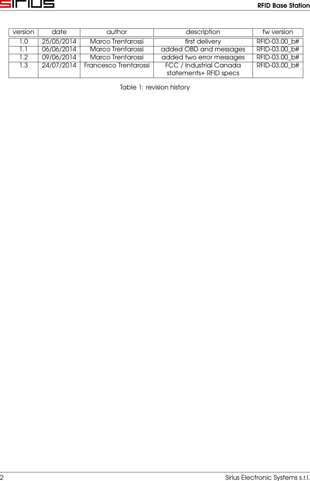
RFID Base Stationversion date author description fw version1.0 25/05/2014 Marco Trentarossi first delivery RFID-03.00_b#1.1 06/06/2014 Marco Trentarossi added OBD and messages RFID-03.00_b#1.2 09/06/2014 Marco Trentarossi added two error messages RFID-03.00_b#1.3 24/07/2014 Francesco Trentarossi FCC / Industrial Canadastatements+ RFID specsRFID-03.00_b#Table 1: revision history2 Sirius Electronic Systems s.r.l.
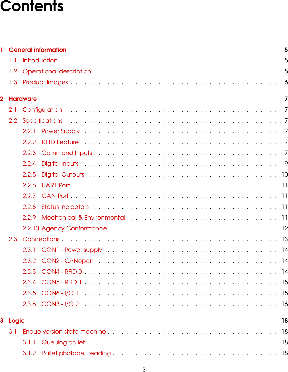
Contents1 General information 51.1 Introduction ............................................... 51.2 Operational description ........................................ 51.3 Product images ............................................. 62 Hardware 72.1 Configuration .............................................. 72.2 Specifications .............................................. 72.2.1 Power Supply .......................................... 72.2.2 RFID Feature .......................................... 72.2.3 Command Inputs ........................................ 72.2.4 Digital Inputs ........................................... 92.2.5 Digital Outputs ......................................... 102.2.6 UART Port ............................................ 112.2.7 CAN Port ............................................. 112.2.8 Status Indicators ........................................ 112.2.9 Mechanical & Environmental ................................ 112.2.10 Agency Conformance .................................... 122.3 Connections ............................................... 132.3.1 CON1 - Power supply ..................................... 142.3.2 CON2 - CANopen ....................................... 142.3.3 CON4 - RFID 0 .......................................... 142.3.4 CON5 - RFID 1 .......................................... 152.3.5 CON6 - I/O 1 .......................................... 152.3.6 CON3 - I/O 2 .......................................... 163 Logic 183.1 Enque version state machine ..................................... 183.1.1 Queuing pallet ......................................... 183.1.2 Pallet photocell reading .................................... 183
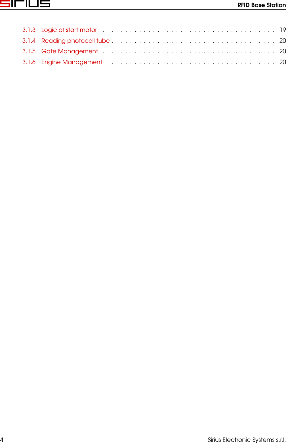
RFID Base Station3.1.3 Logic of start motor ...................................... 193.1.4 Reading photocell tube .................................... 203.1.5 Gate Management ...................................... 203.1.6 Engine Management ..................................... 204 Sirius Electronic Systems s.r.l.
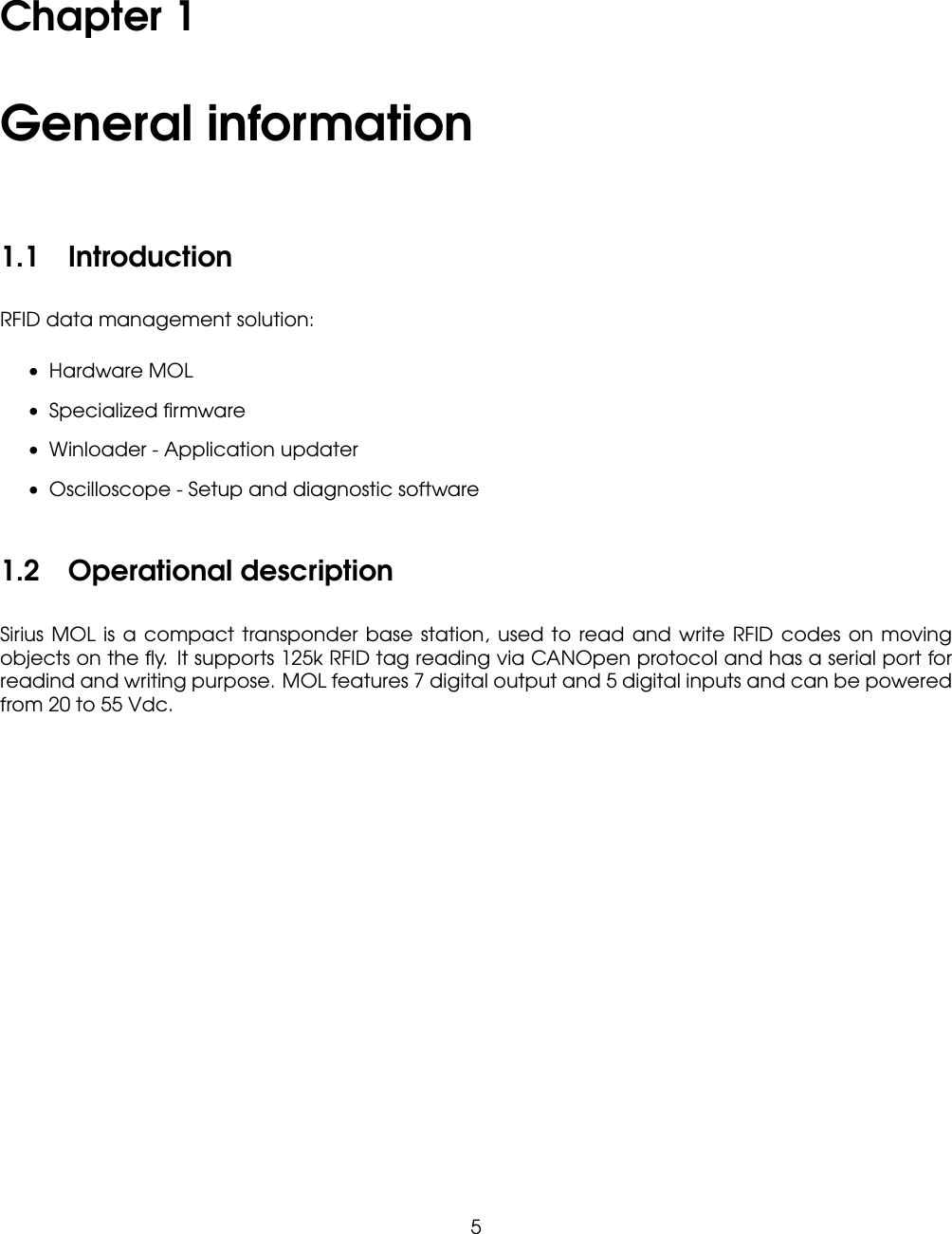
Chapter 1General information1.1 IntroductionRFID data management solution:• Hardware MOL• Specialized firmware• Winloader - Application updater• Oscilloscope - Setup and diagnostic software1.2 Operational descriptionSirius MOL is a compact transponder base station, used to read and write RFID codes on movingobjects on the fly. It supports 125k RFID tag reading via CANOpen protocol and has a serial port forreadind and writing purpose. MOL features 7 digital output and 5 digital inputs and can be poweredfrom 20 to 55 Vdc.5
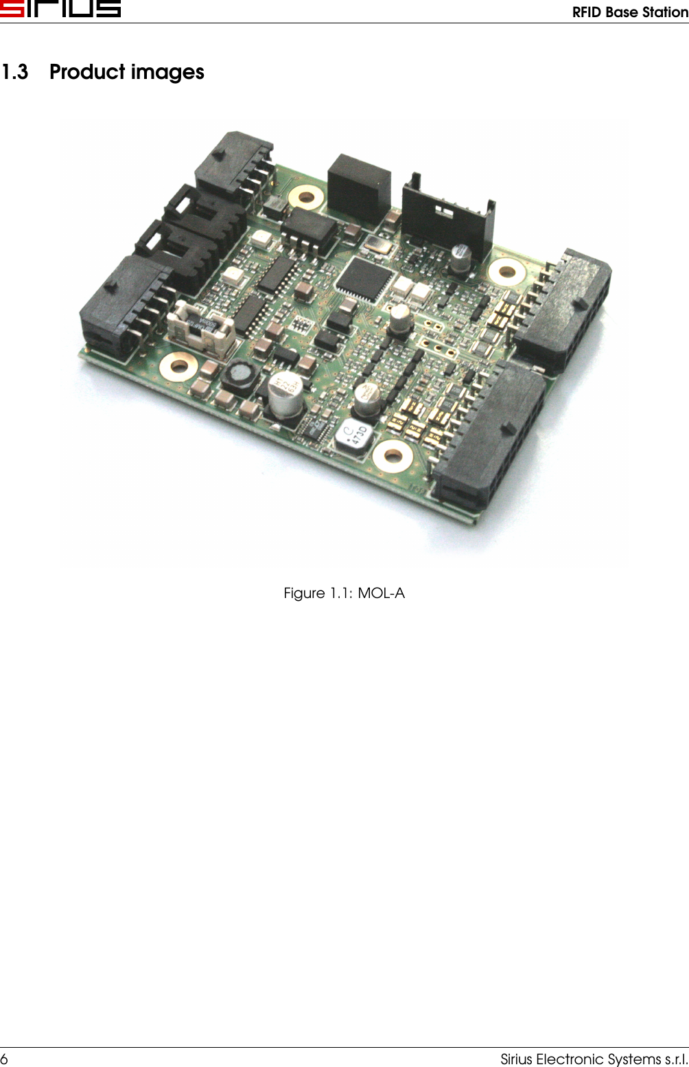
RFID Base Station1.3 Product imagesFigure 1.1: MOL-A6 Sirius Electronic Systems s.r.l.
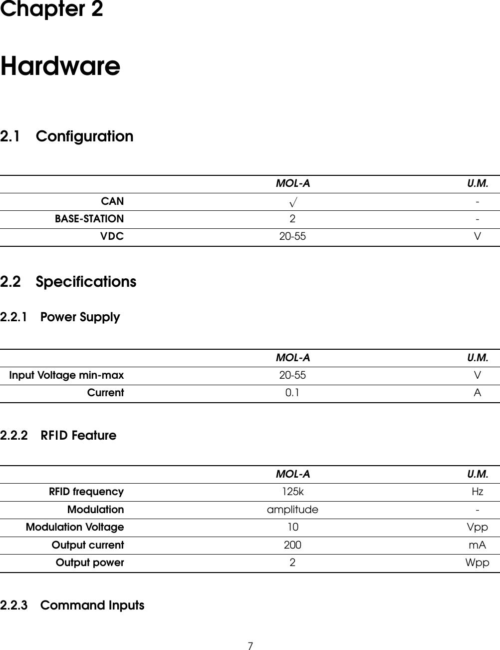
Chapter 2Hardware2.1 ConfigurationMOL-A U.M.CAN √-BASE-STATION 2 -VDC 20-55 V2.2 Specifications2.2.1 Power SupplyMOL-A U.M.Input Voltage min-max 20-55 VCurrent 0.1 A2.2.2 RFID FeatureMOL-A U.M.RFID frequency 125k HzModulation amplitude -Modulation Voltage 10 VppOutput current 200 mAOutput power 2Wpp2.2.3 Command Inputs7
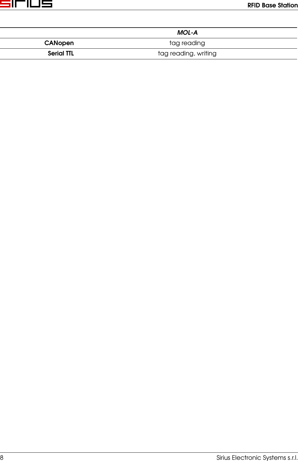
RFID Base StationMOL-ACANopen tag readingSerial TTL tag reading, writing8 Sirius Electronic Systems s.r.l.
RFID Base Station2.2.4 Digital InputsMOL-ANumber, type 5, non-insulatedAll inputs operating from 24V with RC filterLogic levels Vin-LO < 5.6V, Vin-HI > 13V[IN0..4] 2 Medium Speed inputs with 22us RCCurrent rating 10mA @ 24VFigure 2.1: MS InputsSirius Electronic Systems s.r.l. 9
RFID Base Station2.2.5 Digital OutputsMOL-ANumber, type 7, non-insulated[OUT0..6] Current-sourcing MOSFET at 24V (PNP)Current rating 200mA with PTC protectionFigure 2.2: Output10 Sirius Electronic Systems s.r.l.
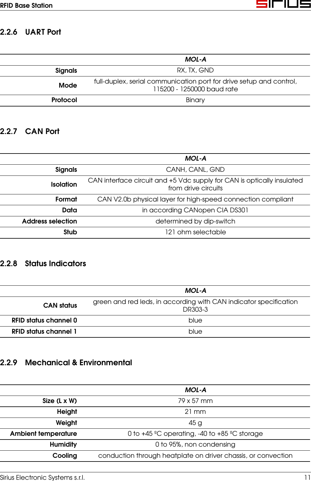
RFID Base Station2.2.6 UART PortMOL-ASignals RX, TX, GNDMode full-duplex, serial communication port for drive setup and control,115200 - 1250000 baud rateProtocol Binary2.2.7 CAN PortMOL-ASignals CANH, CANL, GNDIsolation CAN interface circuit and +5 Vdc supply for CAN is optically insulatedfrom drive circuitsFormat CAN V2.0b physical layer for high-speed connection compliantData in according CANopen CIA DS301Address selection determined by dip-switchStub 121 ohm selectable2.2.8 Status IndicatorsMOL-ACAN status green and red leds, in according with CAN indicator specificationDR303-3RFID status channel 0 blueRFID status channel 1 blue2.2.9 Mechanical & EnvironmentalMOL-ASize (L x W) 79 x 57 mmHeight 21 mmWeight 45 gAmbient temperature 0 to +45 ºC operating, -40 to +85 ºC storageHumidity 0 to 95%, non condensingCooling conduction through heatplate on driver chassis, or convectionSirius Electronic Systems s.r.l. 11
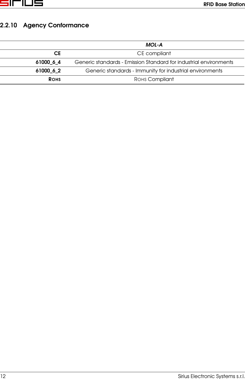
RFID Base Station2.2.10 Agency ConformanceMOL-ACE CE compliant61000_6_4 Generic standards - Emission Standard for industrial environments61000_6_2 Generic standards - Immunity for industrial environmentsROHS ROHS Compliant12 Sirius Electronic Systems s.r.l.
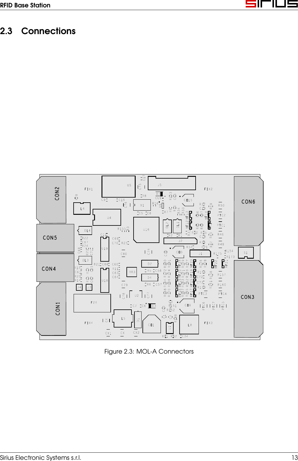
RFID Base Station2.3 ConnectionsFigure 2.3: MOL-A ConnectorsSirius Electronic Systems s.r.l. 13
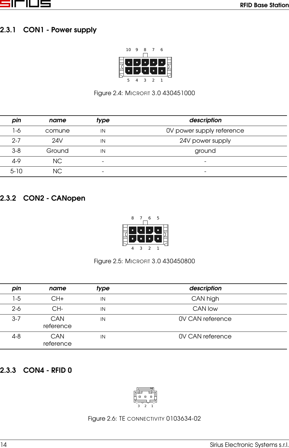
RFID Base Station2.3.1 CON1 - Power supply12345678910Figure 2.4: MICROFIT 3.0 430451000pin name type description1-6 comune IN 0V power supply reference2-7 24V IN 24V power supply3-8 Ground IN ground4-9 NC - -5-10 NC - -2.3.2 CON2 - CANopen12345678Figure 2.5: MICROFIT 3.0 430450800pin name type description1-5 CH+ IN CAN high2-6 CH- IN CAN low3-7 CANreferenceIN 0V CAN reference4-8 CANreferenceIN 0V CAN reference2.3.3 CON4 - RFID 0123Figure 2.6: TE CONNECTIVITY 0103634-0214 Sirius Electronic Systems s.r.l.
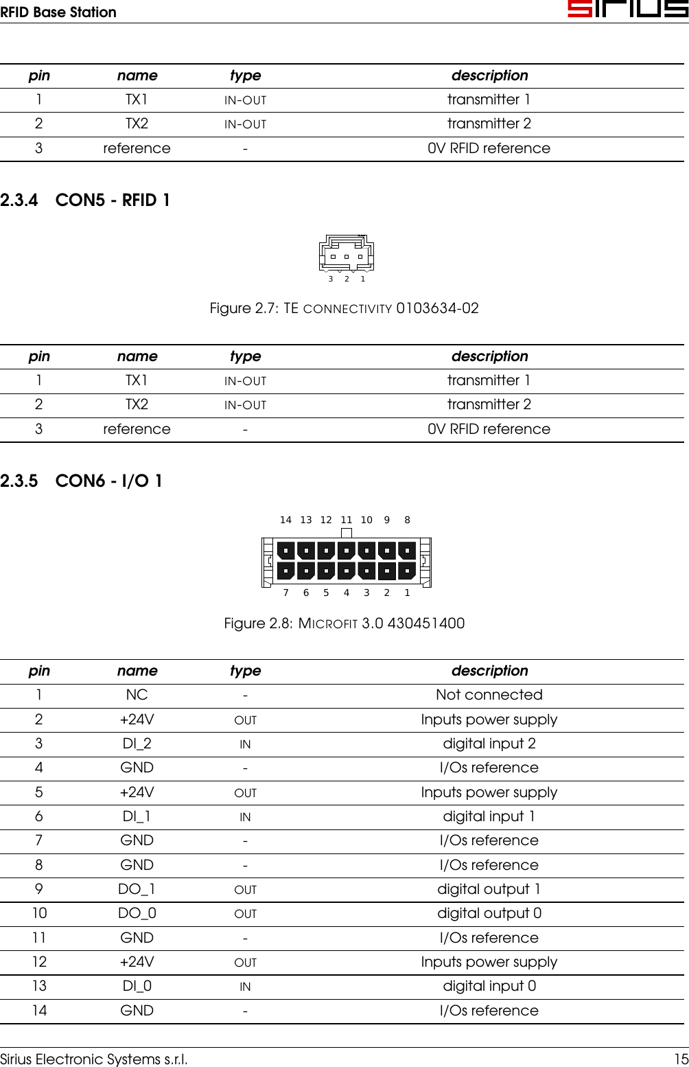
RFID Base Stationpin name type description1 TX1 IN-OUT transmitter 12 TX2 IN-OUT transmitter 23 reference - 0V RFID reference2.3.4 CON5 - RFID 1123Figure 2.7: TE CONNECTIVITY 0103634-02pin name type description1 TX1 IN-OUT transmitter 12 TX2 IN-OUT transmitter 23 reference - 0V RFID reference2.3.5 CON6 - I/O 11234567891011121314Figure 2.8: MICROFIT 3.0 430451400pin name type description1 NC - Not connected2 +24V OUT Inputs power supply3 DI_2 IN digital input 24 GND - I/Os reference5 +24V OUT Inputs power supply6 DI_1 IN digital input 17 GND - I/Os reference8 GND - I/Os reference9 DO_1 OUT digital output 110 DO_0 OUT digital output 011 GND - I/Os reference12 +24V OUT Inputs power supply13 DI_0 IN digital input 014 GND - I/Os referenceSirius Electronic Systems s.r.l. 15
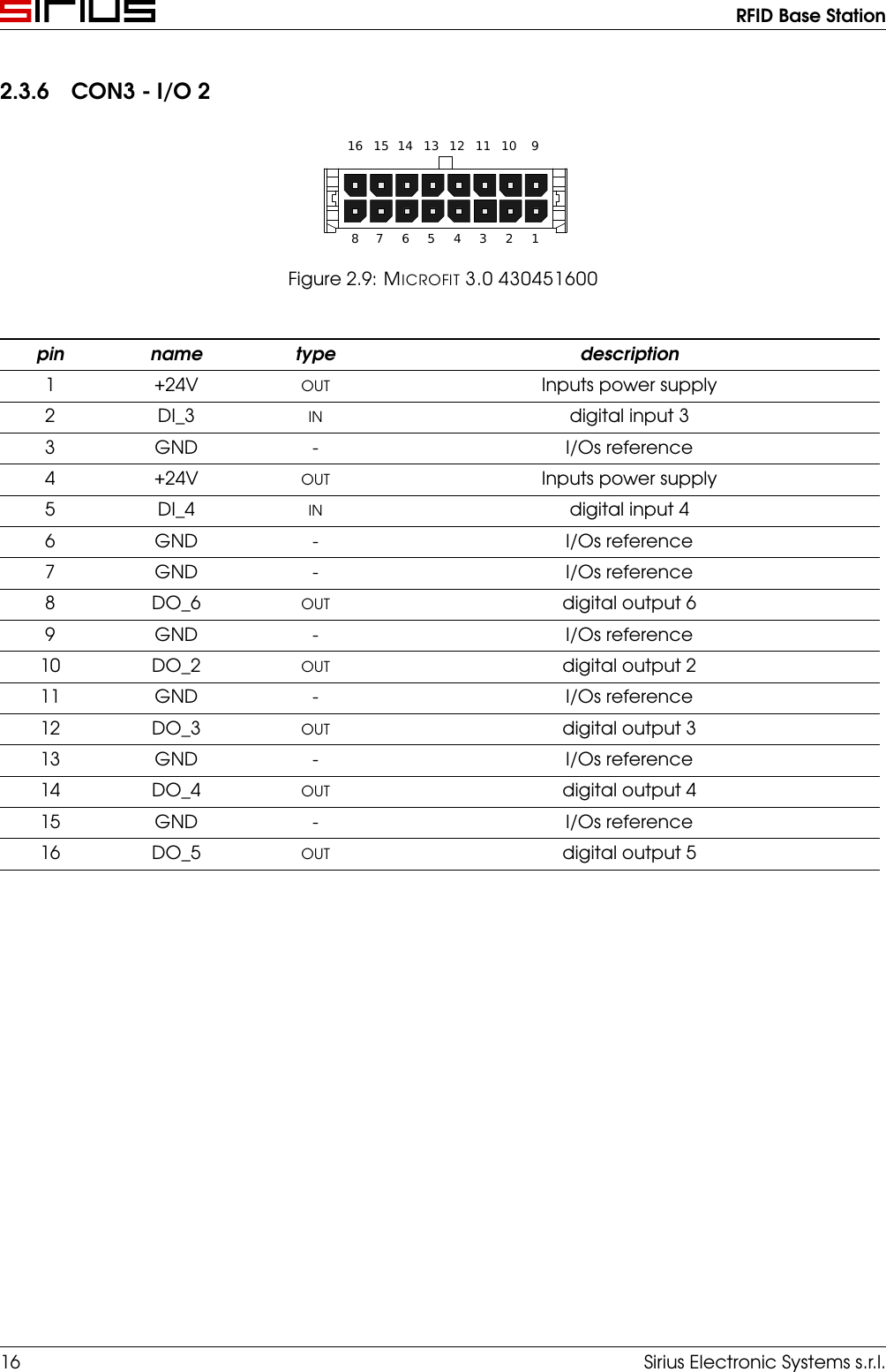
RFID Base Station2.3.6 CON3 - I/O 212345678910111213141516Figure 2.9: MICROFIT 3.0 430451600pin name type description1 +24V OUT Inputs power supply2 DI_3 IN digital input 33 GND - I/Os reference4 +24V OUT Inputs power supply5 DI_4 IN digital input 46 GND - I/Os reference7 GND - I/Os reference8 DO_6 OUT digital output 69 GND - I/Os reference10 DO_2 OUT digital output 211 GND - I/Os reference12 DO_3 OUT digital output 313 GND - I/Os reference14 DO_4 OUT digital output 415 GND - I/Os reference16 DO_5 OUT digital output 516 Sirius Electronic Systems s.r.l.
RFID Base StationFCC StatementNote: This equipment has been tested and found to comply with the limits for a Class A digital device,pursuant to part 15 of the FCC Rules. These limits are designed to provide reasonable protectionagainst harmful interference when the equipment is operated in a commercial environment. Thisequipment generates, uses, and can radiate radio frequency energy and, if not installed and used inaccordance with the instruction manual, may cause harmful interference to radio communications.Operation of this equipment in a residential area is likely to cause harmful interference in which casethe user will be required to correct the interference at his own expense.Changes or modifications not expressly approved by the party responsible for compliance could voidthe user’s authority to operate the equipment.Industry Canada statementThis device complies with Industry Canada licence-exempt RSS standard(s). Operation is subject tothe following two conditions:1. this device may not cause interference, and2. this device must accept any interference, including interference that may cause undesiredoperation of the device.Le présent appareil est conforme aux CNR d’Industrie Canada applicables aux appareils radio ex-empts de licence. L’exploitation est autorisée aux deux conditions suivantes :1. l’appareil ne doit pas produire de brouillage, et2. l’utilisateur de l’appareil doit accepter tout brouillage radioélectrique subi, même si le brouil-lage est susceptible d’en compromettre le fonctionnement.CAN ICES-3 (A)/NMB-3(A)Sirius Electronic Systems s.r.l. 17
Chapter 3Logic3.1 Enque version state machine3.1.1 Queuing palletSetting the variable enqueue = 1 activates the insertion of the read pallet in a queue, before beingdisposed of by the deviation.The tail is 4 pallets deep.Just read a pallet on the antenna inserts into the queue, if it is not already present. Otherwise it couldbe the same pallet, moving in front of the antenna, recurs periodically.When an ID is read, the related rfidCnt timer is preset.3.1.2 Pallet photocell readingThe photocell of the pallet is read constantly, generating events of rising/falling edge.Rising edgeOn the rising edge following actions take place:1. the first ID is picked up in this queue2. Whether the rfidCnt timer is still countdown means that you have just read, then the ID is deletedfrom the list to be processed. In this phase the value of rfidCnt is compared to determine if theantenna is too close / far.3. Whether the rfidCnt timer has finished the countdown means that it was a long time betweenthe antenna and the photocell. Since we are in mode enque delete the ID from the list andhowever process the pallet.4. we reset the variable Temp_coll that will serve to determine the speed of the pallet18
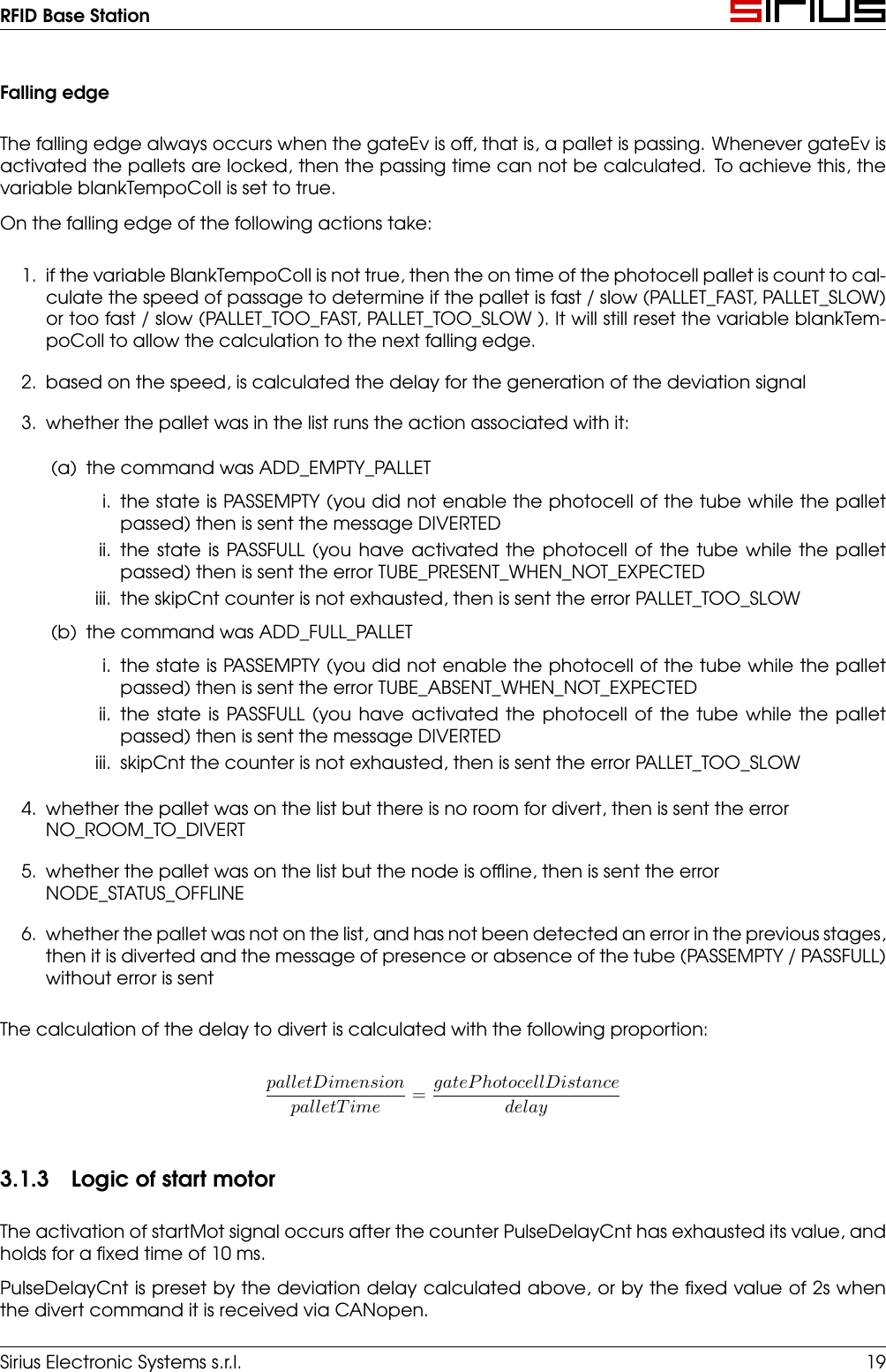
RFID Base StationFalling edgeThe falling edge always occurs when the gateEv is off, that is, a pallet is passing. Whenever gateEv isactivated the pallets are locked, then the passing time can not be calculated. To achieve this, thevariable blankTempoColl is set to true.On the falling edge of the following actions take:1. if the variable BlankTempoColl is not true, then the on time of the photocell pallet is count to cal-culate the speed of passage to determine if the pallet is fast / slow (PALLET_FAST, PALLET_SLOW)or too fast / slow (PALLET_TOO_FAST, PALLET_TOO_SLOW ). It will still reset the variable blankTem-poColl to allow the calculation to the next falling edge.2. based on the speed, is calculated the delay for the generation of the deviation signal3. whether the pallet was in the list runs the action associated with it:(a) the command was ADD_EMPTY_PALLETi. the state is PASSEMPTY (you did not enable the photocell of the tube while the palletpassed) then is sent the message DIVERTEDii. the state is PASSFULL (you have activated the photocell of the tube while the palletpassed) then is sent the error TUBE_PRESENT_WHEN_NOT_EXPECTEDiii. the skipCnt counter is not exhausted, then is sent the error PALLET_TOO_SLOW(b) the command was ADD_FULL_PALLETi. the state is PASSEMPTY (you did not enable the photocell of the tube while the palletpassed) then is sent the error TUBE_ABSENT_WHEN_NOT_EXPECTEDii. the state is PASSFULL (you have activated the photocell of the tube while the palletpassed) then is sent the message DIVERTEDiii. skipCnt the counter is not exhausted, then is sent the error PALLET_TOO_SLOW4. whether the pallet was on the list but there is no room for divert, then is sent the errorNO_ROOM_TO_DIVERT5. whether the pallet was on the list but the node is offline, then is sent the errorNODE_STATUS_OFFLINE6. whether the pallet was not on the list, and has not been detected an error in the previous stages,then it is diverted and the message of presence or absence of the tube (PASSEMPTY / PASSFULL)without error is sentThe calculation of the delay to divert is calculated with the following proportion:palletDimensionpalletT ime=gateP hotocellDistancedelay3.1.3 Logic of start motorThe activation of startMot signal occurs after the counter PulseDelayCnt has exhausted its value, andholds for a fixed time of 10 ms.PulseDelayCnt is preset by the deviation delay calculated above, or by the fixed value of 2s whenthe divert command it is received via CANopen.Sirius Electronic Systems s.r.l. 19
RFID Base Station3.1.4 Reading photocell tubeThe photocell tube is read constantly and prepares the flag to confirm the presence of the tube onthe pallet (PASSFULL).If the signal of the photocell tube is active but photocell of the pallet is off, then it sends a first messageof unexpected tube (UNEXPECTED_TUBE). If by the time fotTubeFlt you have repeated signals, thenthe message of light interference on the photocell (TOO_MUCH_UNXP_TUBE) is sent.3.1.5 Gate ManagementThe gate’s electrovalve is activated in case of:1. homeMot signal = 0 (the engine is performing the homing)2. receiving a command of EMERGENCY_GATE_OUT3. receiving a command of HOME_GATE (2s ahead of the start homing)The solenoid valve is turned off:1. homeMot signal = 1 (is not performing a homing)2. receiving a command of EMERGENCY_GATE_INThroughout the time of gate EV activation the timer skipCnt is preset with the skipTmr value. The timerbegins to countdown when the solenoid is off. This timer prevents any deviation that would producethe error PALLET_TOO_SLOW .3.1.6 Engine ManagementThe motor board MOHWhen the board motor turn on, it runs automatically the homing research and resulting in a positionaligned to the track. In this phase the signal homeMot is held at 0. Just finished zeroing, the homeMotgoes to 1.The RFID board MOLWhen the RFID is turn on it sets the state variable homeMotStt to HM_BOOTUP, starts the verificationprocess of homing and then goes into HM_WF_BOOTUP. In this state, it waits for the reset of the cardby toggling the motor signal startMot, every homeMotTmo. After 10 inversions (5 attempts homing)without receiving answers from the card engine, says that the communication between the twoboards is not working by sending the error message COMM_MOT_FAULT.In the state HM_READY the system observes the signal homeMot = 0 to send the error HOMING. Thenit goes into the HM_WF_TMO state waiting for homing (homeMot = 1). If this does not happen withinthe time homeMotTmo the error HOMING_TIMEOUT is sent. If the homing finish properly it send a nullmessage (all 0).20 Sirius Electronic Systems s.r.l.

Navigation menu