Inpeco Spa a Socio Unico CANLANSI001 Radio Frequency Identification Device for Sample carriers User Manual Sirius Digital Servo Drivers

Inpeco Spa a Socio Unico Radio Frequency Identification Device for Sample carriers Sirius Digital Servo Drivers

Users Manual
Sirius Digital Analog I/O PeripheralRevision: 1.41July 24, 2014
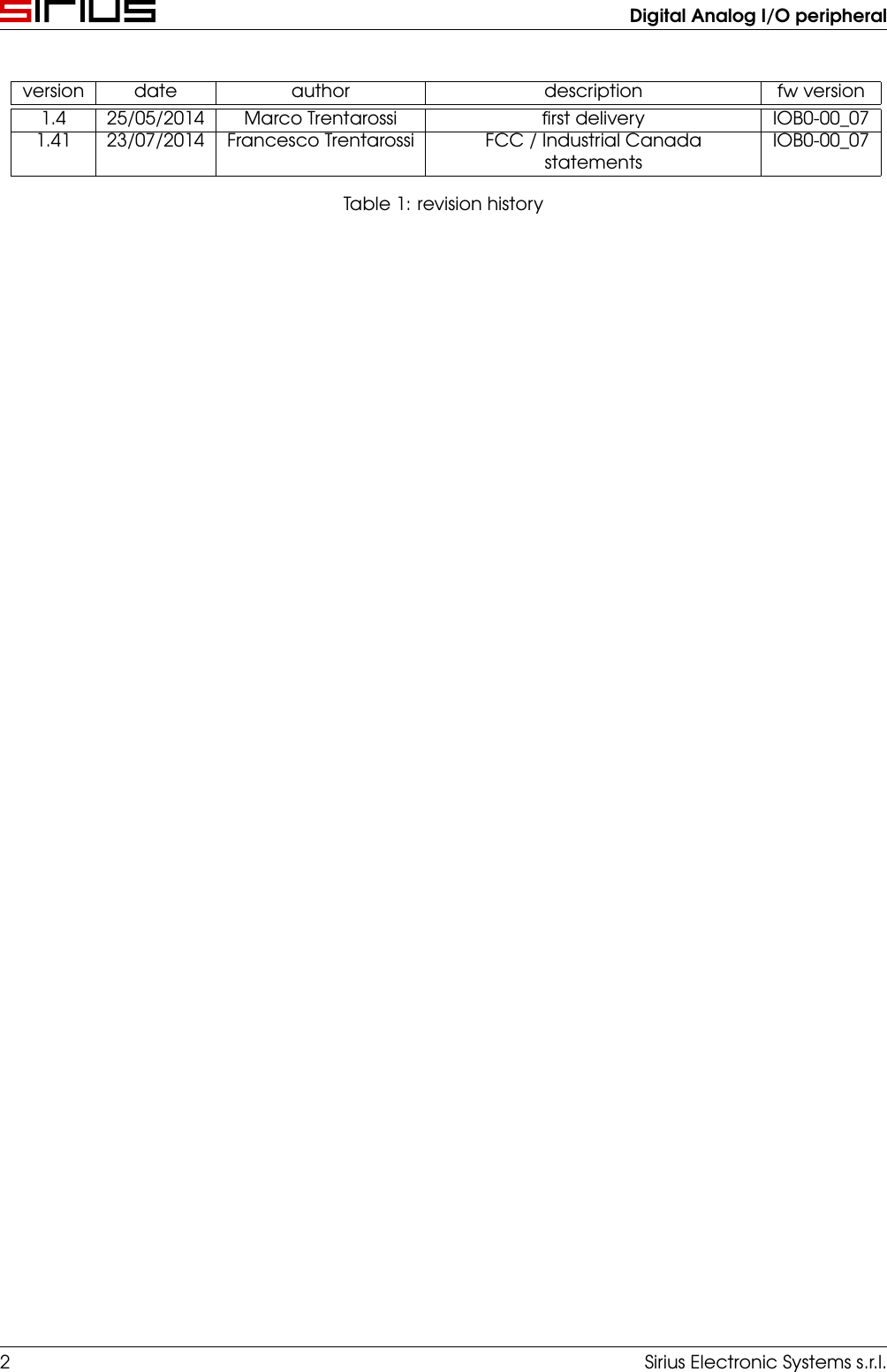
Digital Analog I/O peripheralversion date author description fw version1.4 25/05/2014 Marco Trentarossi first delivery IOB0-00_071.41 23/07/2014 Francesco Trentarossi FCC / Industrial CanadastatementsIOB0-00_07Table 1: revision history2 Sirius Electronic Systems s.r.l.
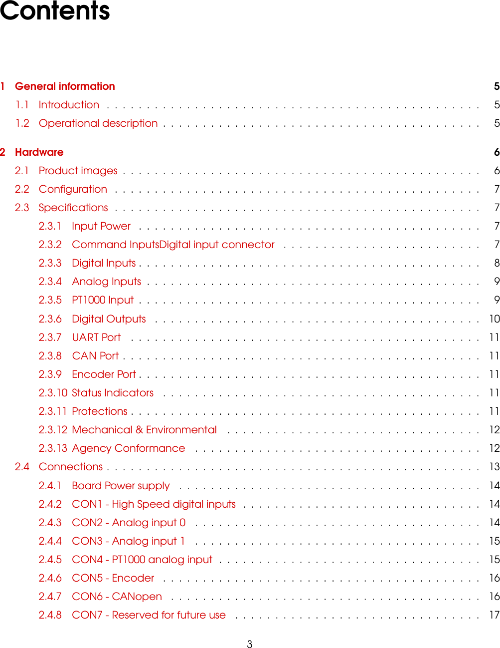
Contents1 General information 51.1 Introduction ............................................... 51.2 Operational description ........................................ 52 Hardware 62.1 Product images ............................................. 62.2 Configuration .............................................. 72.3 Specifications .............................................. 72.3.1 Input Power ........................................... 72.3.2 Command InputsDigital input connector ......................... 72.3.3 Digital Inputs ........................................... 82.3.4 Analog Inputs .......................................... 92.3.5 PT1000 Input ........................................... 92.3.6 Digital Outputs ......................................... 102.3.7 UART Port ............................................ 112.3.8 CAN Port ............................................. 112.3.9 Encoder Port ........................................... 112.3.10 Status Indicators ........................................ 112.3.11 Protections ............................................ 112.3.12 Mechanical & Environmental ................................ 122.3.13 Agency Conformance .................................... 122.4 Connections ............................................... 132.4.1 Board Power supply ...................................... 142.4.2 CON1 - High Speed digital inputs .............................. 142.4.3 CON2 - Analog input 0 .................................... 142.4.4 CON3 - Analog input 1 .................................... 152.4.5 CON4 - PT1000 analog input ................................. 152.4.6 CON5 - Encoder ........................................ 162.4.7 CON6 - CANopen ....................................... 162.4.8 CON7 - Reserved for future use ............................... 173
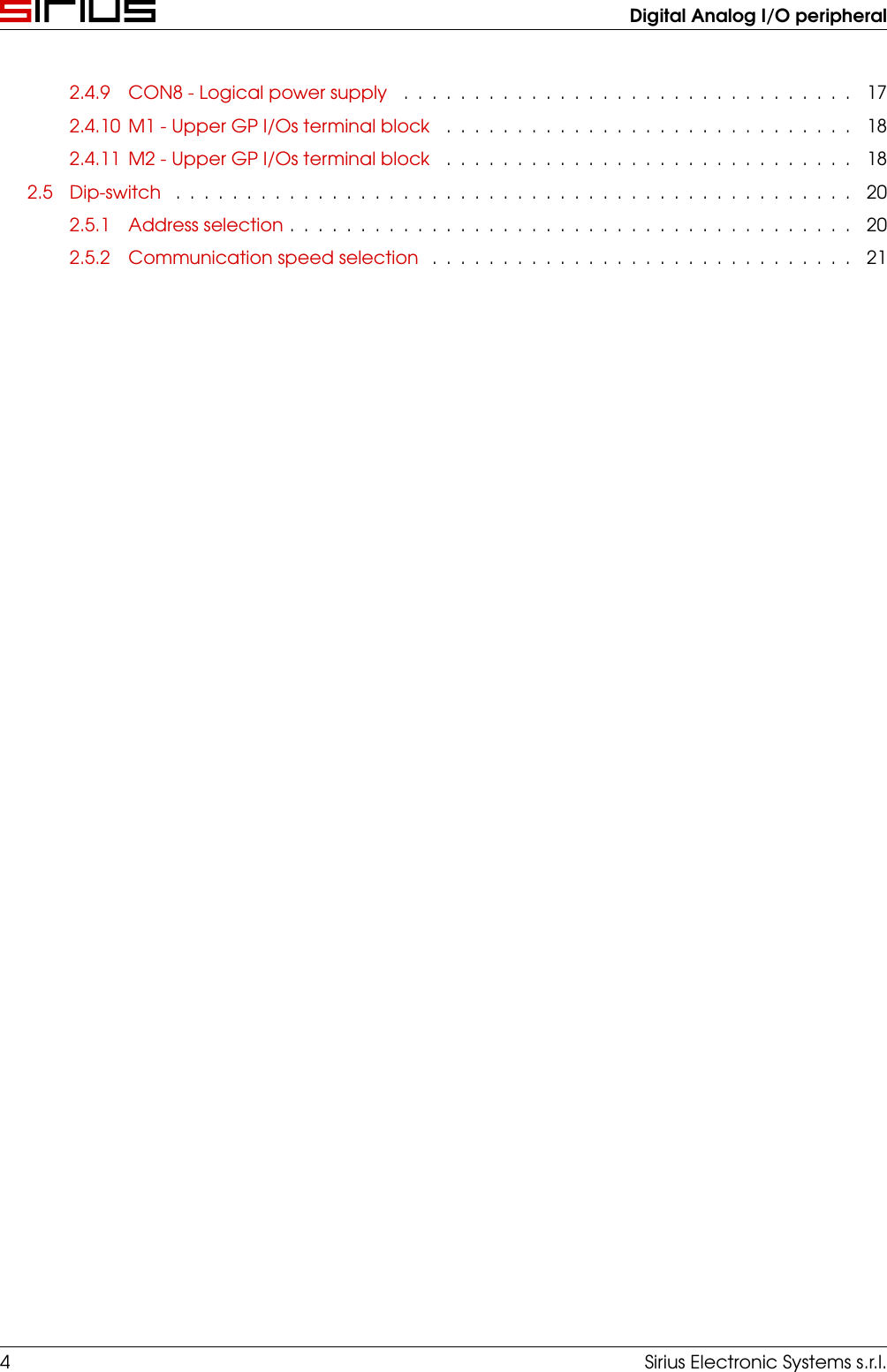
Digital Analog I/O peripheral2.4.9 CON8 - Logical power supply ................................ 172.4.10 M1 - Upper GP I/Os terminal block ............................. 182.4.11 M2 - Upper GP I/Os terminal block ............................. 182.5 Dip-switch ................................................ 202.5.1 Address selection ........................................ 202.5.2 Communication speed selection .............................. 214 Sirius Electronic Systems s.r.l.
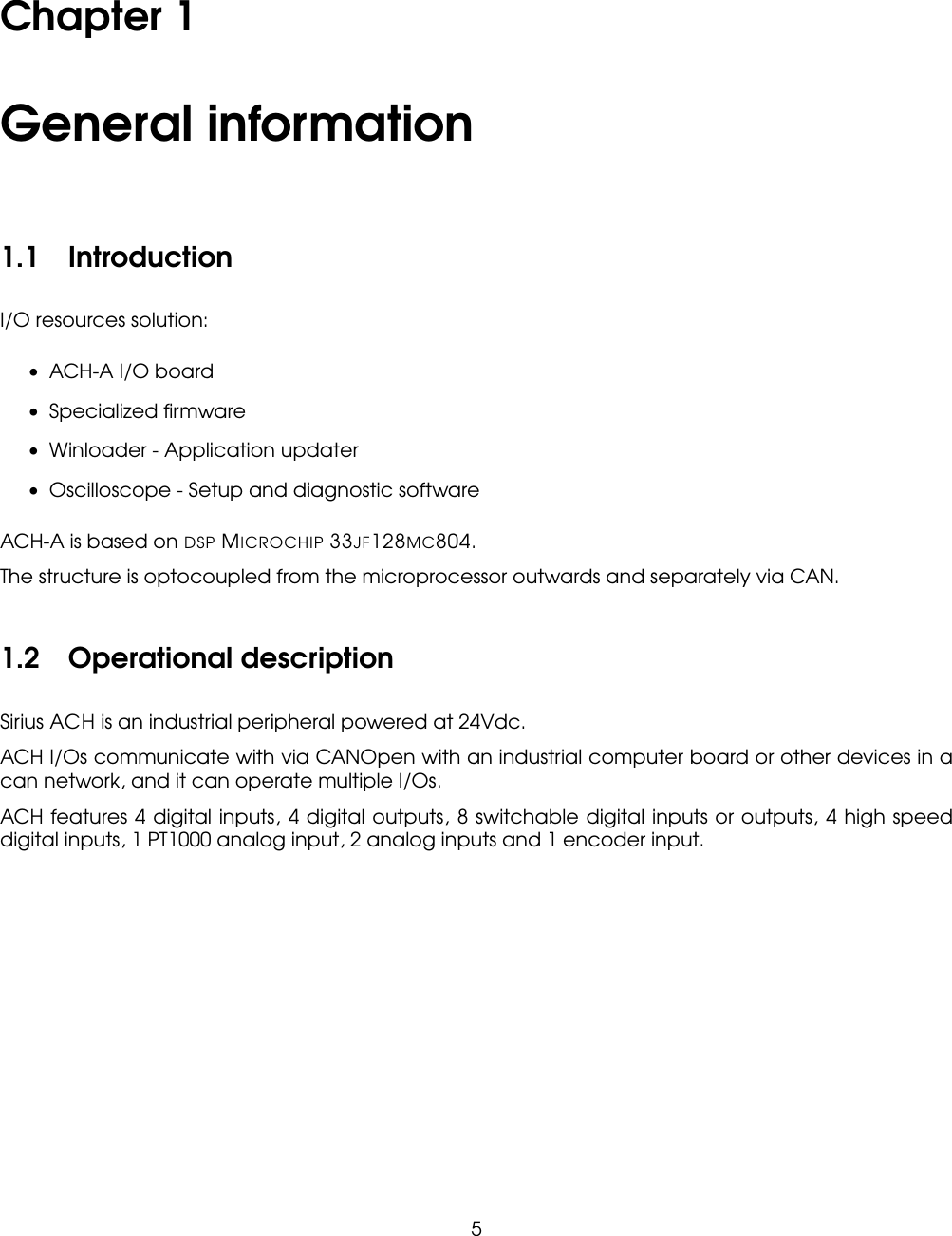
Chapter 1General information1.1 IntroductionI/O resources solution:• ACH-A I/O board• Specialized firmware• Winloader - Application updater• Oscilloscope - Setup and diagnostic softwareACH-A is based on DSP MICROCHIP 33JF128MC804.The structure is optocoupled from the microprocessor outwards and separately via CAN.1.2 Operational descriptionSirius ACH is an industrial peripheral powered at 24Vdc.ACH I/Os communicate with via CANOpen with an industrial computer board or other devices in acan network, and it can operate multiple I/Os.ACH features 4 digital inputs, 4 digital outputs, 8 switchable digital inputs or outputs, 4 high speeddigital inputs, 1 PT1000 analog input, 2 analog inputs and 1 encoder input.5
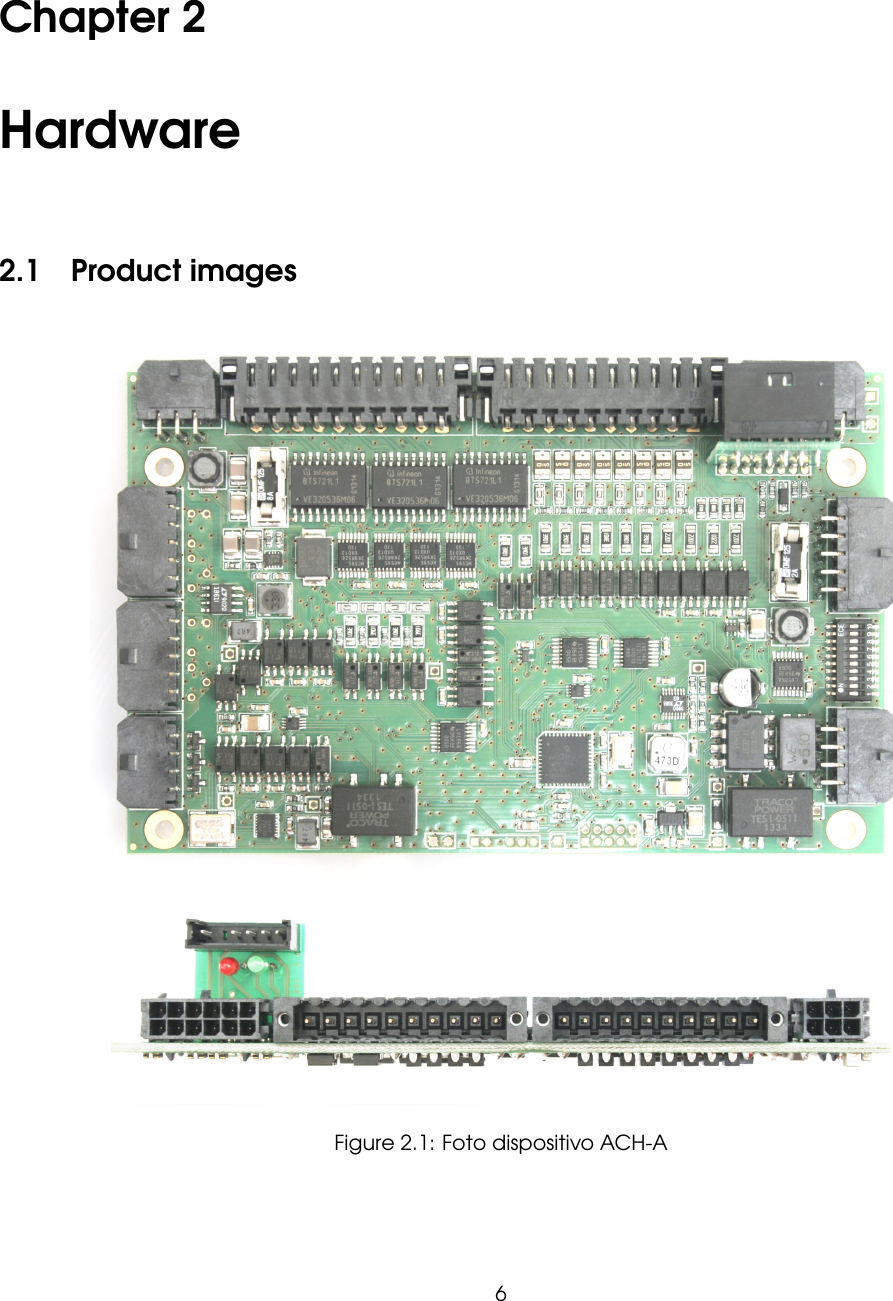
Chapter 2Hardware2.1 Product imagesFigure 2.1: Foto dispositivo ACH-A6
Digital Analog I/O peripheral2.2 ConfigurationQuantity DescriptionDIGITAL INPUT 4 General purpose digital inputsDIGITAL OUTPUT 4 General purpose digital outputsADVANCED DIGITALI/Os8 Configurable digital inputs / outputsFAST DIGITAL INPUT 4 High speed digital inputsPT1000 INPUT 1 PT1000 analog inputANALOG INPUT 2 4/20mA or 0-10V analog inputsENCODER INPUT 1 5V TTL encoder input2.3 Specifications2.3.1 Input PowerACH-A U.M.Input Voltage min-max 16-34 Vlogic current 0.060 AMax current* 19 A*with all inputs/outputs active2.3.2 Command InputsDigital input connectorACH-ACANopen digital outputs / analog parametersSerial TTL digital outputs / analog parametersSirius Electronic Systems s.r.l. 7
Digital Analog I/O peripheral2.3.3 Digital InputsACH-ANumber, type up to 16,All inputs operating from 24V or 5V, software programmable, with RC filterLogic levels Vin-LO < 5.6V, Vin-HI > 13V @24VVin-LO < 1.6V, Vin-HI > 3.5V @5VGP [IN0..11] up to 12 General Purpose inputs with 4.7us RCHS [IN12..15] 4 High Speed input with 3.3us RC and interrupt capabilityCurrent rating 10mA @ 24/5VFigure 2.2: HS InputsFigure 2.3: GP Inputs8 Sirius Electronic Systems s.r.l.
Digital Analog I/O peripheral2.3.4 Analog InputsACH-ANumber, type 2, insulatedAll inputs operating from 0 to 10V or 4 to 20mAAN [IN0,1] 2 x 12 bits (LTC1861) /16 bits (LTC18It does not detect the lack o65)analog inputsFigure 2.4: 12/16 bits Analog Inputs2.3.5 PT1000 InputACH-ANumber, type 1, insulatedAll inputs operating at 1000 ohmAN [IN2] 1 x 16 bits analog inputsFigure 2.5: 16 bits Analog InputSirius Electronic Systems s.r.l. 9
Digital Analog I/O peripheral2.3.6 Digital OutputsACH-ANumber, type 12, insulated[OUT0..11] Current-sourcing MOSFET at 24V (PNP)1 parallel, 2 parallel, 4 parallelNominal Load Current 2.9A, 4.3A, 6.3AESD protection yesFigure 2.6: Output10 Sirius Electronic Systems s.r.l.
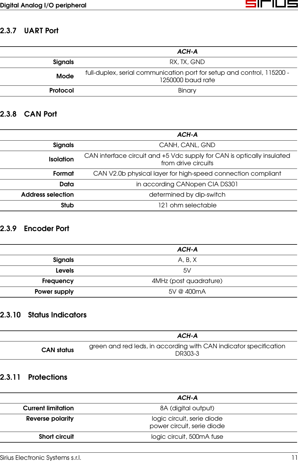
Digital Analog I/O peripheral2.3.7 UART PortACH-ASignals RX, TX, GNDMode full-duplex, serial communication port for setup and control, 115200 -1250000 baud rateProtocol Binary2.3.8 CAN PortACH-ASignals CANH, CANL, GNDIsolation CAN interface circuit and +5 Vdc supply for CAN is optically insulatedfrom drive circuitsFormat CAN V2.0b physical layer for high-speed connection compliantData in according CANopen CIA DS301Address selection determined by dip-switchStub 121 ohm selectable2.3.9 Encoder PortACH-ASignals A, B, XLevels 5VFrequency 4MHz (post quadrature)Power supply 5V @ 400mA2.3.10 Status IndicatorsACH-ACAN status green and red leds, in according with CAN indicator specificationDR303-32.3.11 ProtectionsACH-ACurrent limitation 8A (digital output)Reverse polarity logic circuit, serie diodepower circuit, serie diodeShort circuit logic circuit, 500mA fuseSirius Electronic Systems s.r.l. 11
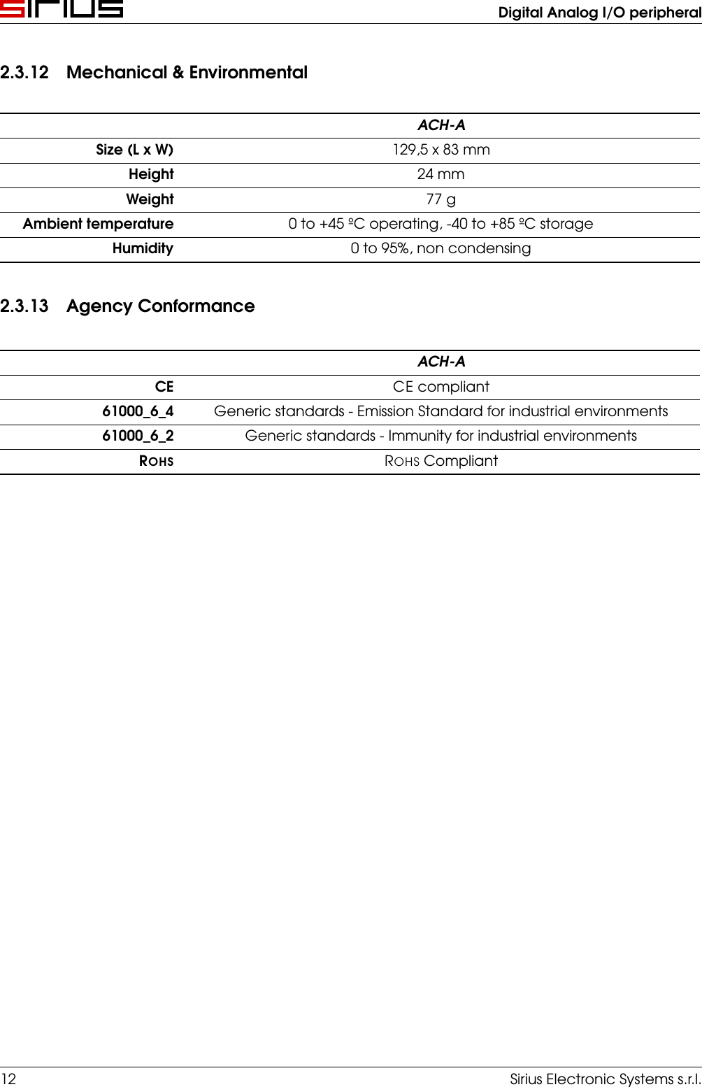
Digital Analog I/O peripheral2.3.12 Mechanical & EnvironmentalACH-ASize (L x W) 129,5 x 83 mmHeight 24 mmWeight 77 gAmbient temperature 0 to +45 ºC operating, -40 to +85 ºC storageHumidity 0 to 95%, non condensing2.3.13 Agency ConformanceACH-ACE CE compliant61000_6_4 Generic standards - Emission Standard for industrial environments61000_6_2 Generic standards - Immunity for industrial environmentsROHS ROHS Compliant12 Sirius Electronic Systems s.r.l.
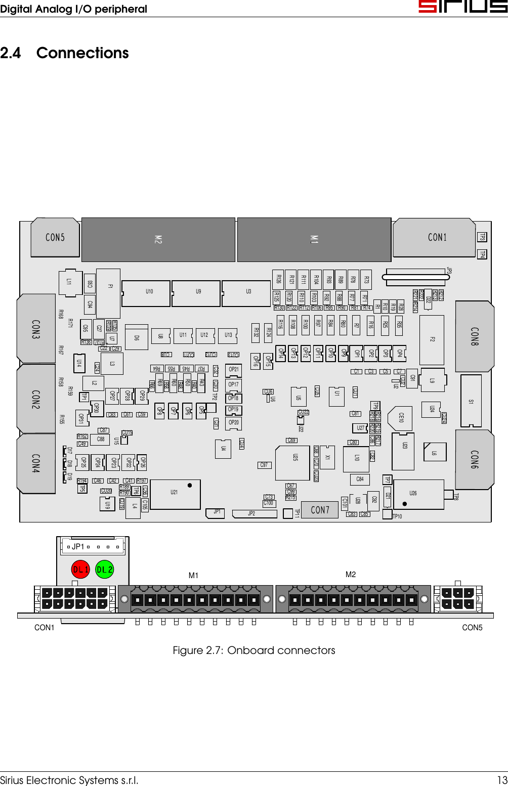
Digital Analog I/O peripheral2.4 ConnectionsM2CON5M1CON1TP3JP3TP4L11F1C93U10 U9 U3R126R121R104R111R89R93R78R73R221R222R213R212R168C94R130R125R122R110R120R112 R106R103R90R95R88R92R81R71R77R74R10R1R28R19R214D22CON3C95R171C27R139R135U8U11 U12 U13R132R116R124R108R97R100R80R84R7R16R25R35CON8R167R136C22R137C29U7D6CU8CU11CU12CU13OP14OP13OP12OP11OP9OP10OP1OP2OP3OP4F2U14C24L3R55 R64R45C32R37OP21OP16OP15C1 C3 C5 C7C91CON2R158TP1R159L2OP27OP28R66OP29R58R69R60R40R48R50C30R43TP2OP17OP18CU6U6U5CU5U1CU1U2CU2L9R155OP31OP30C61C63 C59OP7OP8OP6OP5OP19 CU22 C81TP9 R218R216CE10CU24U24S1R162C87C88U15CU15C31OP20C69U22U27R220R219 R217C86CON4C49OP25D18D17OP24OP23OP22OP26U4CU4U25C70C68X1C80L10C82U23L6CON6R194D19C46 C41C42 R197C97CU23C84TP7TP5CU20U19CU19R190R189C56TP6C105U21C100C73C67C99R215U28C101C92D21U26TP8L4JP1 JP2TP11C85C83 TP10JP1CON1 CON5M2M1Figure 2.7: Onboard connectorsSirius Electronic Systems s.r.l. 13
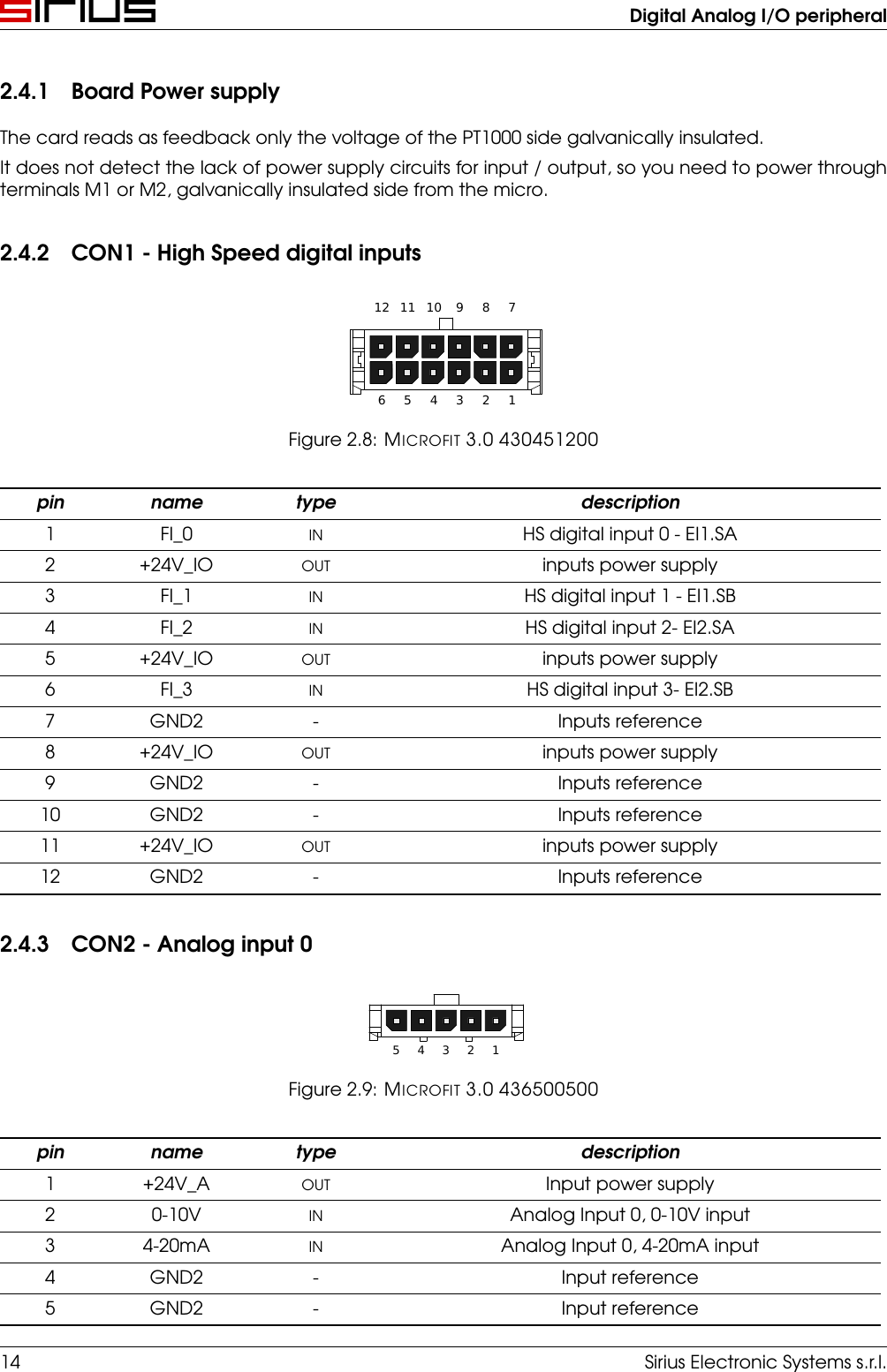
Digital Analog I/O peripheral2.4.1 Board Power supplyThe card reads as feedback only the voltage of the PT1000 side galvanically insulated.It does not detect the lack of power supply circuits for input / output, so you need to power throughterminals M1 or M2, galvanically insulated side from the micro.2.4.2 CON1 - High Speed digital inputs123456789101112Figure 2.8: MICROFIT 3.0 430451200pin name type description1 FI_0 IN HS digital input 0 - EI1.SA2 +24V_IO OUT inputs power supply3 FI_1 IN HS digital input 1 - EI1.SB4 FI_2 IN HS digital input 2- EI2.SA5 +24V_IO OUT inputs power supply6 FI_3 IN HS digital input 3- EI2.SB7 GND2 - Inputs reference8 +24V_IO OUT inputs power supply9 GND2 - Inputs reference10 GND2 - Inputs reference11 +24V_IO OUT inputs power supply12 GND2 - Inputs reference2.4.3 CON2 - Analog input 012345Figure 2.9: MICROFIT 3.0 436500500pin name type description1 +24V_A OUT Input power supply2 0-10V IN Analog Input 0, 0-10V input3 4-20mA IN Analog Input 0, 4-20mA input4 GND2 - Input reference5 GND2 - Input reference14 Sirius Electronic Systems s.r.l.
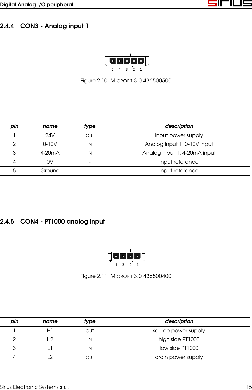
Digital Analog I/O peripheral2.4.4 CON3 - Analog input 112345Figure 2.10: MICROFIT 3.0 436500500pin name type description1 24V OUT Input power supply2 0-10V IN Analog Input 1, 0-10V input3 4-20mA IN Analog Input 1, 4-20mA input4 0V - Input reference5 Ground - Input reference2.4.5 CON4 - PT1000 analog input1234Figure 2.11: MICROFIT 3.0 436500400pin name type description1 H1 OUT source power supply2 H2 IN high side PT10003 L1 IN low side PT10004 L2 OUT drain power supplySirius Electronic Systems s.r.l. 15
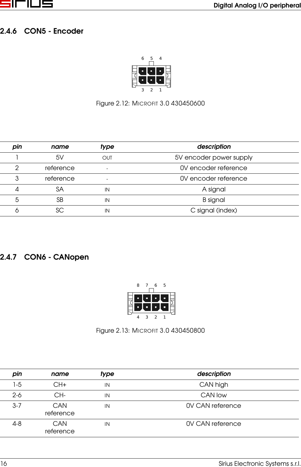
Digital Analog I/O peripheral2.4.6 CON5 - Encoder123456Figure 2.12: MICROFIT 3.0 430450600pin name type description1 5V OUT 5V encoder power supply2 reference -0V encoder reference3 reference -0V encoder reference4 SA IN A signal5 SB IN B signal6 SC IN C signal (index)2.4.7 CON6 - CANopen12345678Figure 2.13: MICROFIT 3.0 430450800pin name type description1-5 CH+ IN CAN high2-6 CH- IN CAN low3-7 CANreferenceIN 0V CAN reference4-8 CANreferenceIN 0V CAN reference16 Sirius Electronic Systems s.r.l.
Digital Analog I/O peripheral2.4.8 CON7 - Reserved for future useCON7 supplies 5V, 3.3V and 6 signals to the CPU for piggy back expansions.2.4.9 CON8 - Logical power supply12345678910Figure 2.14: MICROFIT 3.0 430451000pin name type description1-6 comune IN 0V power supply reference2-7 24V IN 24V power supply3-8 Ground IN ground4-9 NC - -5-10 NC - -Sirius Electronic Systems s.r.l. 17
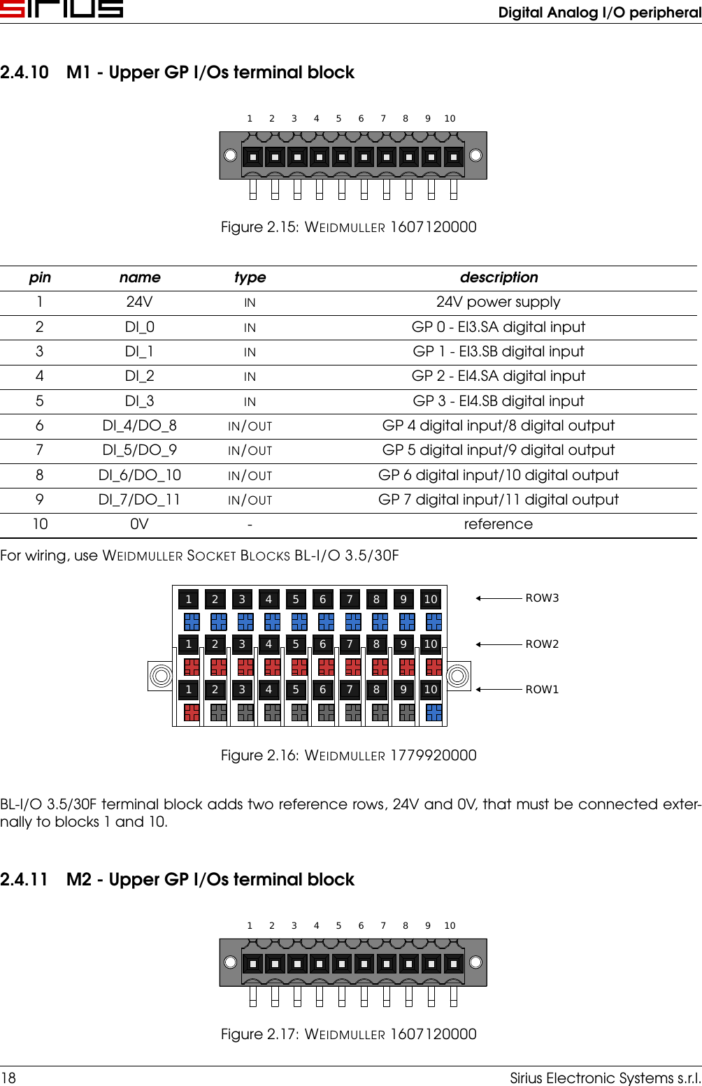
Digital Analog I/O peripheral2.4.10 M1 - Upper GP I/Os terminal block1 2 3 4 5 6 7 8 9 10Figure 2.15: WEIDMULLER 1607120000pin name type description1 24V IN 24V power supply2 DI_0 IN GP 0 - EI3.SA digital input3 DI_1 IN GP 1 - EI3.SB digital input4 DI_2 IN GP 2 - EI4.SA digital input5 DI_3 IN GP 3 - EI4.SB digital input6 DI_4/DO_8 IN/OUT GP 4 digital input/8 digital output7 DI_5/DO_9 IN/OUT GP 5 digital input/9 digital output8 DI_6/DO_10 IN/OUT GP 6 digital input/10 digital output9 DI_7/DO_11 IN/OUT GP 7 digital input/11 digital output10 0V - referenceFor wiring, use WEIDMULLER SOCKET BLOCKS BL-I/O 3.5/30F1 2 3 4 5 6 7 8 9 101 2 3 4 5 6 7 8 9 101 2 3 4 5 6 7 8 9 10 ROW3ROW2ROW1Figure 2.16: WEIDMULLER 1779920000BL-I/O 3.5/30F terminal block adds two reference rows, 24V and 0V, that must be connected exter-nally to blocks 1 and 10.2.4.11 M2 - Upper GP I/Os terminal block1 2 3 4 5 6 7 8 9 10Figure 2.17: WEIDMULLER 160712000018 Sirius Electronic Systems s.r.l.
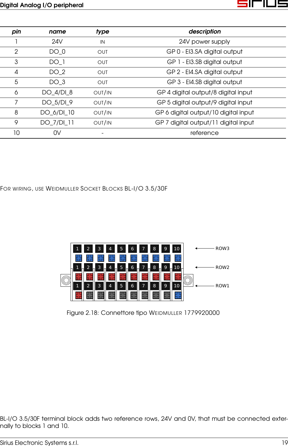
Digital Analog I/O peripheralpin name type description1 24V IN 24V power supply2 DO_0 OUT GP 0 - EI3.SA digital output3 DO_1 OUT GP 1 - EI3.SB digital output4 DO_2 OUT GP 2 - EI4.SA digital output5 DO_3 OUT GP 3 - EI4.SB digital output6 DO_4/DI_8 OUT/IN GP 4 digital output/8 digital input7 DO_5/DI_9 OUT/IN GP 5 digital output/9 digital input8 DO_6/DI_10 OUT/IN GP 6 digital output/10 digital input9 DO_7/DI_11 OUT/IN GP 7 digital output/11 digital input10 0V - referenceFOR WIRING,USE WEIDMULLER SOCKET BLOCKS BL-I/O 3.5/30F1 2 3 4 5 6 7 8 9 101 2 3 4 5 6 7 8 9 101 2 3 4 5 6 7 8 9 10 ROW3ROW2ROW1Figure 2.18: Connettore tipo WEIDMULLER 1779920000BL-I/O 3.5/30F terminal block adds two reference rows, 24V and 0V, that must be connected exter-nally to blocks 1 and 10.Sirius Electronic Systems s.r.l. 19
Digital Analog I/O peripheral2.5 Dip-switchS dip-siwtch is located as in figureM2CON5M1CON1TP3JP3TP4L11F1C93U10 U9 U3R126R121R104R111R89R93R78R73R221R222R213R212R168C94R130R125R122R110R120R112 R106R103R90R95R88R92R81R71R77R74R10R1R28R19R214D22CON3C95R171C27R139R135U8U11 U12 U13R132R116R124R108R97R100R80R84R7R16R25R35CON8R167R136C22R137C29U7D6CU8CU11CU12CU13OP14OP13OP12OP11OP9OP10OP1OP2OP3OP4F2U14C24L3R55 R64R45C32R37OP21OP16OP15C1 C3 C5 C7C91CON2R158TP1R159L2OP27OP28R66OP29R58R69R60R40R48R50C30R43TP2OP17OP18CU6U6U5CU5U1CU1U2CU2L9R155OP31OP30C61C63 C59OP7OP8OP6OP5OP19 CU22 C81TP9 R218R216CE10CU24U24S1R162C87C88U15CU15C31OP20C69U22U27R220R219 R217C86CON4C49OP25D18D17OP24OP23OP22OP26U4CU4U25C70C68X1C80L10C82U23L6CON6R194D19C46 C41C42 R197C97CU23C84TP7TP5CU20U19CU19R190R189C56TP6C105U21C100C73C67C99R215U28C101C92D21U26TP8L4JP1 JP2TP11C85C83 TP10Figure 2.19: dip-switch position2.5.1 Address selectionUsing S1 selector it is possible to change the CAN address of the device.Assigned address is stored in variable CobId.Address can be a number from 0 to 127. Every CAN node must have an unique address.Follows bit weight:Switch PesoS2 ON 1S3 ON 2S4 ON 4S5 ON 8S6 ON 16S7 ON 32S8 ON 64Table 2.1: dip-switch weight20 Sirius Electronic Systems s.r.l.
Digital Analog I/O peripheral2.5.2 Communication speed selectionUsing S1 selector it is possible to change the communication speed of the device.Assigned speed is stored in variable CobBR.Speed can be 125, 250, 500 or 1000 kbps.S10 S9 Baud ratekbpsOFF OFF 125OFF ON 250ON OFF 500ON ON 1000Table 2.2: baud rate selectionSirius Electronic Systems s.r.l. 21
Digital Analog I/O peripheralFCC StatementNote: This equipment has been tested and found to comply with the limits for a Class A digital device,pursuant to part 15 of the FCC Rules. These limits are designed to provide reasonable protectionagainst harmful interference when the equipment is operated in a commercial environment. Thisequipment generates, uses, and can radiate radio frequency energy and, if not installed and used inaccordance with the instruction manual, may cause harmful interference to radio communications.Operation of this equipment in a residential area is likely to cause harmful interference in which casethe user will be required to correct the interference at his own expense.Changes or modifications not expressly approved by the party responsible for compliance could voidthe user’s authority to operate the equipment.Industry Canada statementThis device complies with Industry Canada licence-exempt RSS standard(s). Operation is subject tothe following two conditions:1. this device may not cause interference, and2. this device must accept any interference, including interference that may cause undesiredoperation of the device.Le présent appareil est conforme aux CNR d’Industrie Canada applicables aux appareils radio ex-empts de licence. L’exploitation est autorisée aux deux conditions suivantes :1. l’appareil ne doit pas produire de brouillage, et2. l’utilisateur de l’appareil doit accepter tout brouillage radioélectrique subi, même si le brouil-lage est susceptible d’en compromettre le fonctionnement.CAN ICES-3 (A)/NMB-3(A)22 Sirius Electronic Systems s.r.l.

Navigation menu