Inseego NVWE351 PC EXPRESS CARD User Manual Notices
Novatel Wireless Inc PC EXPRESS CARD Notices
UserManual.wiki
>
Inseego
>
NVWE351 User Manual
Integration Guideline Rev 2.1
Navigation menu
Upload a User Manual
Namespaces
Wiki Guide
HTML
PDF
Info
Views
User Manual
Discussion / Help
Navigation
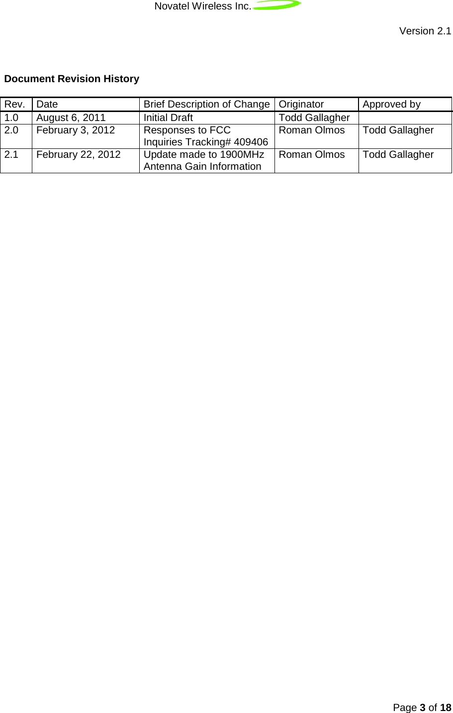
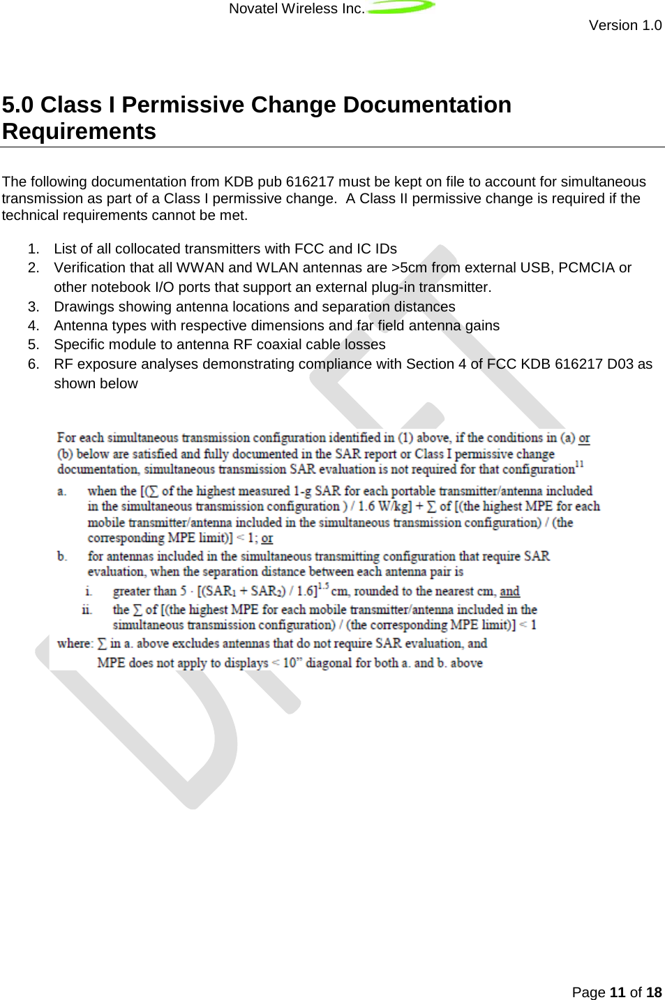
![Novatel Wireless Inc. Version 1.0 Page 16 of 18 If the summation of SAR exceeds the FCC limit, collocation is permitted through a Class I permissive change provided the minimum allowable separation distance derived from the equation below is satisfied. An alternate equation provides the maximum collocated SAR based on a specified separation distance. In addition, the sum of the highest MPE must be less than the corresponding MPE limit as defined in section 4. B) ii) of FCC KDB 616217 D03. 6.6 Portable Device Hosts Max Collocated SAR Vs. Distance 5∗([SARWWAN +SARcollocated1.6 ]1.5)≤Ant _SeparationWWAN −to−CollocatedMinimum separation distance for Collocated Transmitters 5∗([SARWWAN +SARcollocated1.6 ]1.5)≤Ant _SeparationWWAN−to−CollocatedMaximum collocated SAR vs distance SARcollocated=1.6∗(SeparationWWAN−to−Collocated1.5 )23−SARWWAN](https://usermanual.wiki/Inseego/NVWE351/User-Guide-1646986-Page-16.png)