Inseego NVWFB2C PCS CDMA MODEM User Manual FB200C Windows Guide
Novatel Wireless Inc PCS CDMA MODEM FB200C Windows Guide
UserManual.wiki
>
Inseego
>
NVWFB2C User Manual
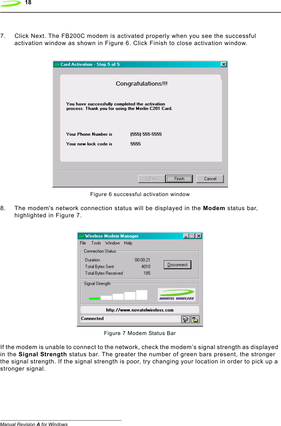
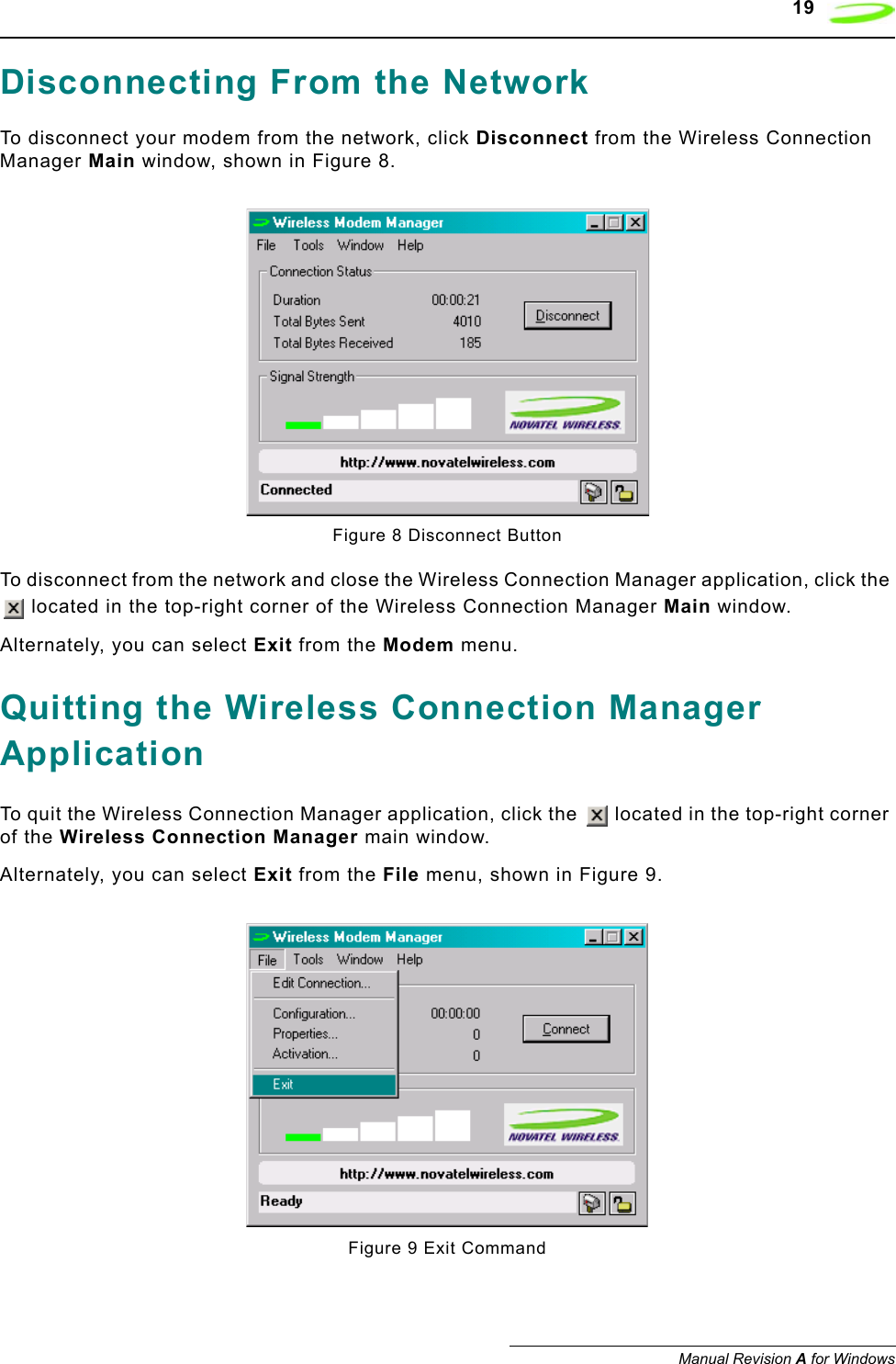
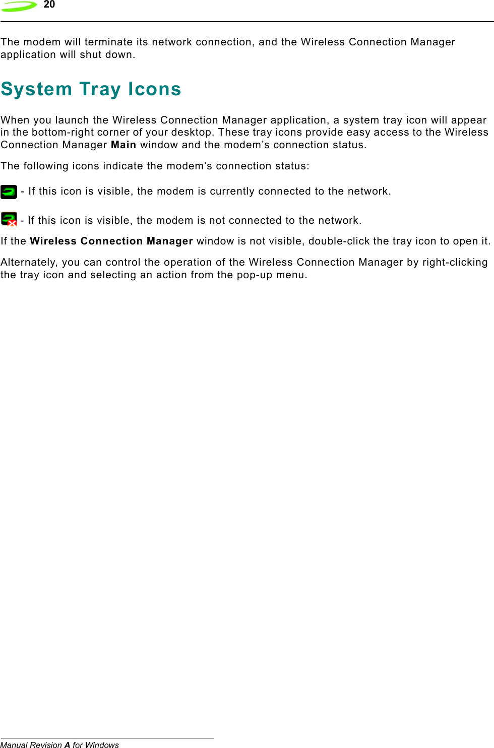
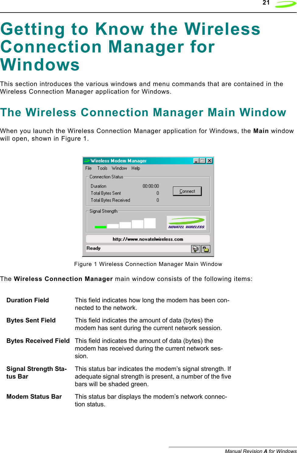
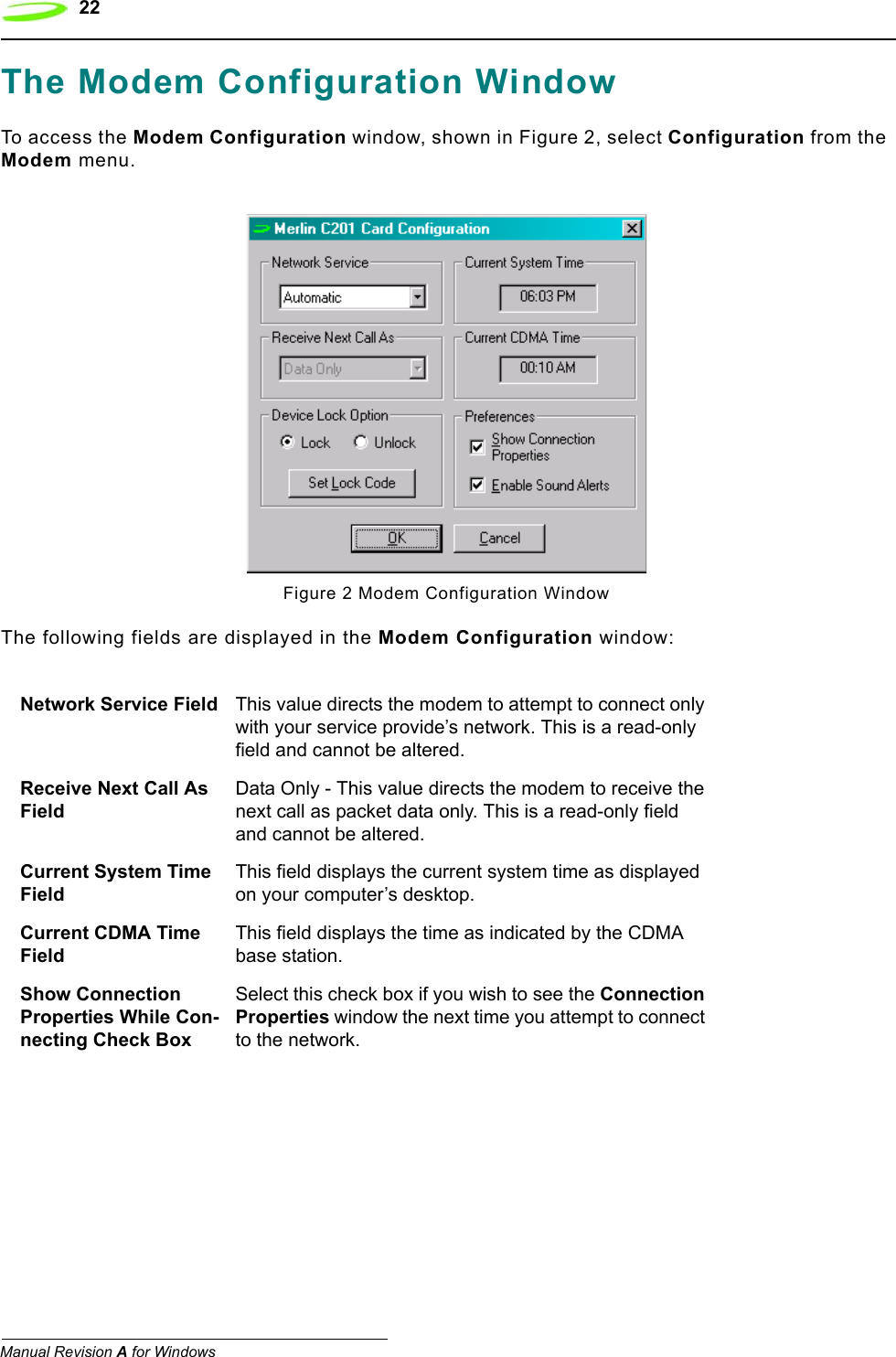
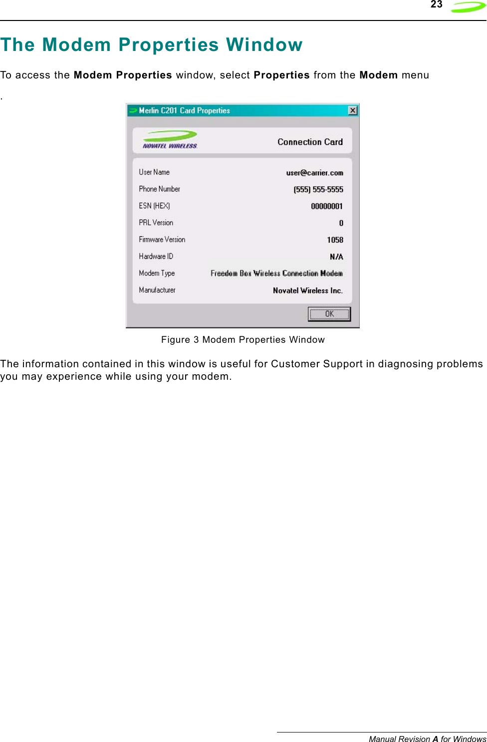
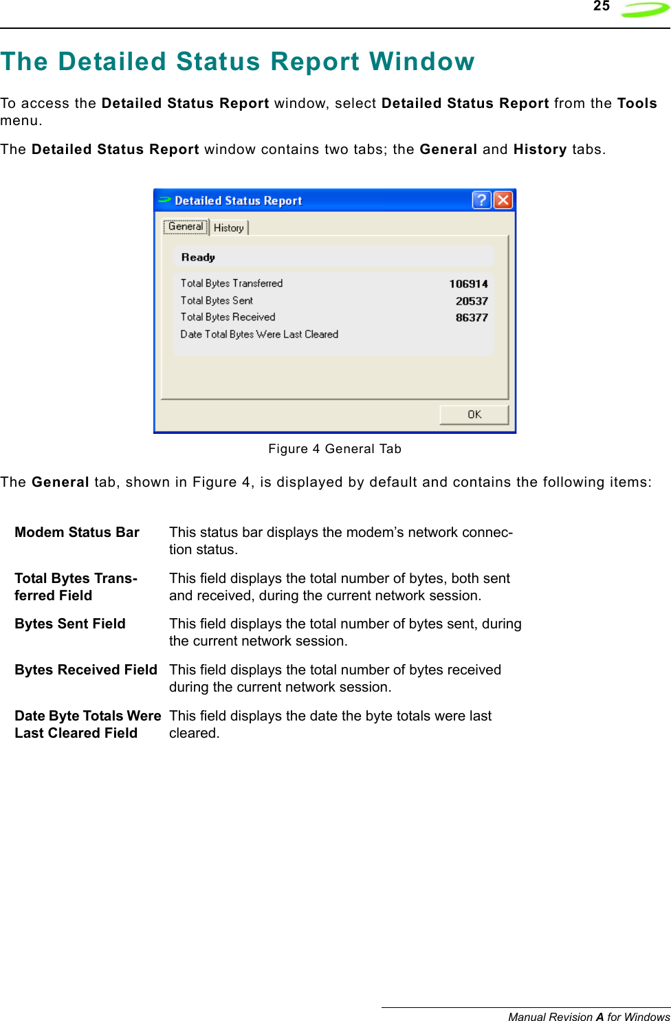
USERS MANUAL
Navigation menu
Upload a User Manual
Namespaces
Wiki Guide
HTML
PDF
Info
Views
User Manual
Discussion / Help
Navigation