Inseego NVWM100 MiFi Hotspot, LTE Only, Bands 2, 4, 5 , 12, 17 User Manual 1

Novatel Wireless Inc MiFi Hotspot, LTE Only, Bands 2, 4, 5 , 12, 17 1

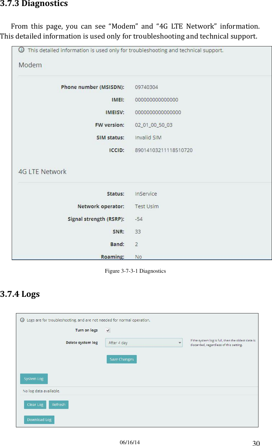
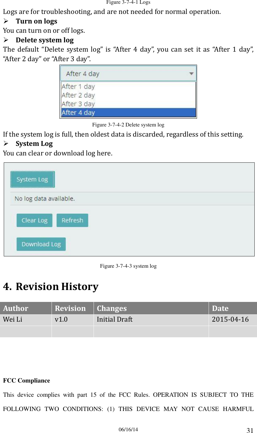
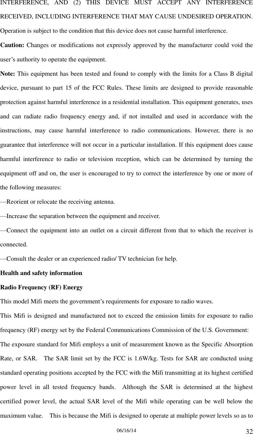
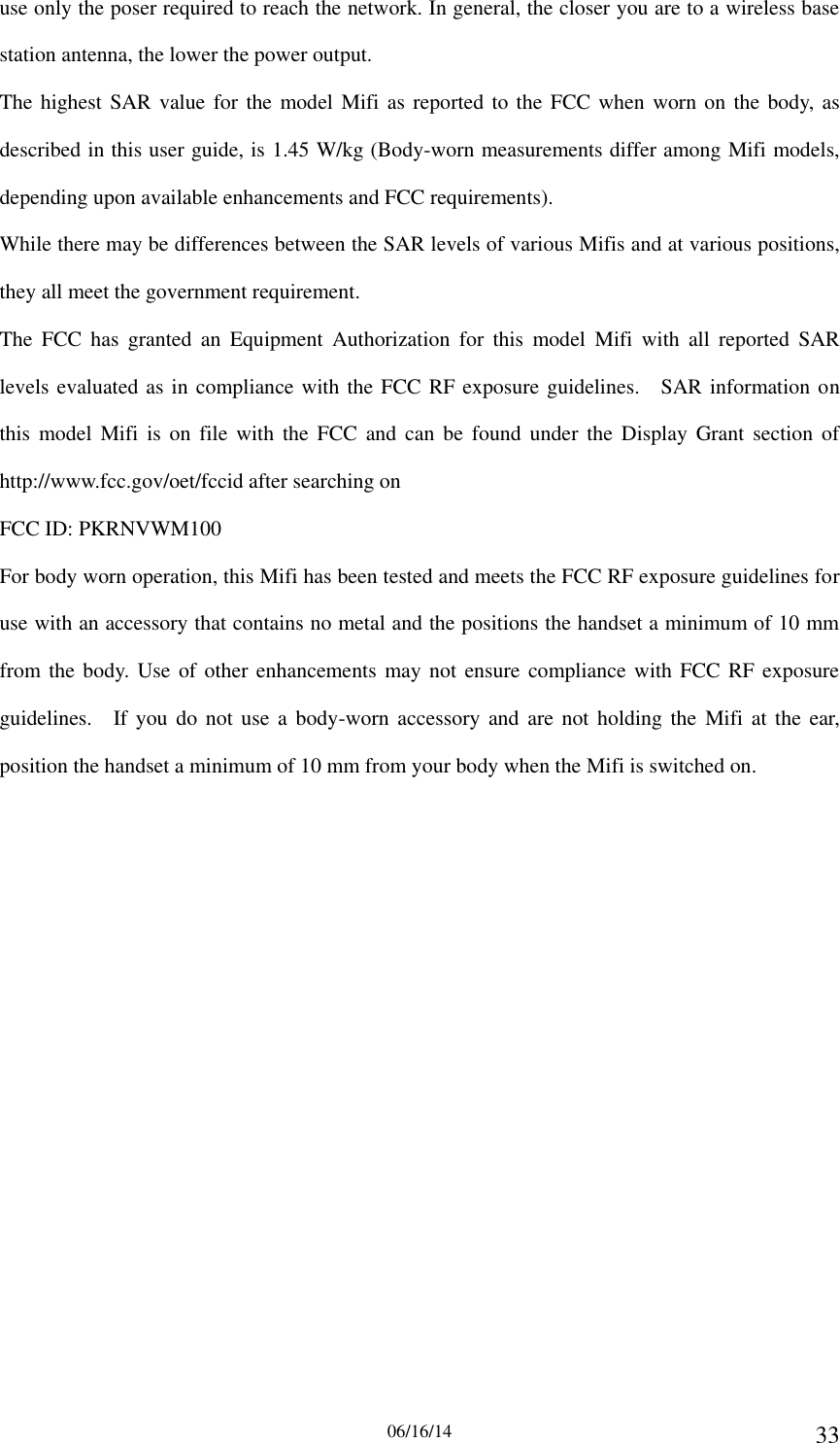
M100 User Manual_20150619

06/16/14 1            LTE MiFi(M100)User Manual
06/16/14 2 Index 1. About this Manual ............................................................................ 3 2. Product Overview ............................................................................ 3 3. Configuring the router ................................................................... 3 3.1 Login ............................................................................................................... 3 3.2 MIFI HOME ...................................................................................................... 4 3.3 CONNECTED DEVICES ..................................................................................... 5 3.4 DATA USAGE .................................................................................................... 7 3.5 SETTINGS ........................................................................................................ 8 3.5.1 Wi-Fi Hotspot .......................................................................................................... 9 3.5.2 Device Settings ...................................................................................................... 13 3.5.3 Mobile Settings ...................................................................................................... 18 3.5.4 Advanced ............................................................................................................... 20 3.6 CUSTOMER SUPPORT .................................................................................... 26 3.7 ABOUT .......................................................................................................... 28 3.7.1 Internet Status ...................................................................................................... 28 3.7.2 Device Info ............................................................................................................. 29 3.7.3 Diagnostics ............................................................................................................ 30 3.7.4 Logs ........................................................................................................................ 30 4. Revision History ............................................................................ 31
06/16/14 3 1. About this Manual The  content  of  this  User  Manual  has  been  made  as  accurate  as  possible. However,  due  to  continual  product  improvements,  specifications  and  other information are subject to change without notice. 2. Product Overview This MiFi supports LTE Band 2/4/5/12/17 (Subject to the configuration of LTE module)  and  it  supports  popular  operating  systems  like  Windows,  Linux  and Mac.   Please refer to the Quick Start Guide that is part of the MiFi supply. Once you have  identified  the  place  for  MiFi  insert  USIM  card  supplied  by  your  service provider at the appropriate place, plug in the adapter in the AC socket and DC in the power port of MiFi. Switch on the power Off/On switch and after few minutes the  MiFi  should  attach  itself  to  the  LTE  network.  It  is  as  simple  as  that.  It  is advised to read this manual at leisure to make best use of the MiFi. 3. Configuring the router The  basic  settings  in  WebGUI  consist  of  six  main  parts  named  MIFI  HOME, CONNECTED  DEVICES,  DATA  USAGE,  SETTINGS,  CUSTOMER  SUPPORT,  and ABOUT. You can login to WebGUI as follows, and configure the settings according to your requirements. Connect the PC to MiFi. Power on the device and waiting for about 40 seconds until  the  device  finished  initializing.  Please  ensure  that  USIM  card  has  been inserted into USIM slot in MiFi. You can also connect the PC to MiFi by WiFi, choose the correct WiFi SSID and input  the  accurate  password  as  the  label  shows.  The  default  WiFi  SSID  is “MiFi-xxxxxx”. 3.1 Login Open your Web browser and enter 192.168.0.1 in the address bar; Login window will popup; When prompted for password, enter the following password. Password: admin
06/16/14 4  Figure 3-1-1 Login page 3.2 MIFI HOME After  successful  login,  the  following  screen  will  appear  and  you  will  see  six main menus on the left bar of the WebGUI. Click “Logout”, the screen will turn to login window. From  this  page,  you  can  also  know  Network  Provider,  Wi-Fi  Network  Name, Wi-Fi Network Password, Signal, Battery Power, Connected Devices, Data Usage and Messages, Help&Support. You can also edit Wi-Fi Network Name and change Wi-Fi Network Password.  Figure 3-2-1 MIFI HOME
06/16/14 5 3.3 CONNECTED DEVICES On this page, you can see Connected Devices, Blocked Devices and change max connections.  Figure 3-3-1 CONNECTED DEVICES “Connected Devices”  shows the  clients that  connect to the  device,  include  by USB cable and WiFi.  Figure 3-3-2 Connected Devices The  default  max  connection  is  15,  click  “Change  Max  Connections”  button,  it will  access  Wi-Fi  Hotspot  page,  you  can  change  max  connections  in  the  “Max Wi-Fi connections” field.  Figure 3-3-3 Change Max Connections
06/16/14 6  Figure 3-3-4 Wi-Fi Hotspot page Click “Edit” button to edit the type and hostname of the client.  Figure 3-3-5 Edit button  Figure 3-3-6 Edit page Choose  a  WiFi  client  and  click  “Block”  button,  this  client  will  display  in  the “Blocked Devices” and disconnect with the device.  Figure 3-3-7 Block button “Blocked Devices” shows the clients that be blocked  Figure 3-3-8 Blocked devices page
06/16/14 7 Choose a  blocked client  and click  “Unblock”  button, this  client will disappear from  the  “Blocked  Devices”  list,  it  will  show  in  the  “Connected  Devices”  again after it connects to the device.  Figure 3-3-8 Unblock button 3.4 DATA USAGE The  estimated  data  usage  is  displayed  in  this  page,  you  can  manage  your account and view your bill at TBD.  Figure 3-4-1 Data Usage   “Alert Level” area shows the data and days remaining, you can click “Reset Data Counter” to clear all the data.
06/16/14 8  Figure 3-4-2 Alert level area   “Usage alert level” and “ Cycle start data” can be changed in the “Settings” area.  Figure 3-4-3 Settings 3.5 SETTINGS On this page, you can see Wi-Fi Hotspot, Device Settings, Mobile Settings and Advanced.
06/16/14 9  Figure 3-5-1 Settings 3.5.1 Wi-Fi Hotspot Clicking on the “Wi-Fi Hotspot” tab will take you to the “Wi-Fi Hotspot” page. On this page, the settings about WiFi can be viewed and changed.
06/16/14 10  Figure 3-5-1-1 Wi-Fi Hotspot  Wi-Fi – ON/OFF Turn on allow Wi-Fi devices to connect to this device. Wi-Fi devices will not connect to this device after turn off.  Wi-Fi name(SSID) To identify your wireless network, a name called the SSID (Service Set Identifier) is used. You can set it to anything you like and you should make sure that your SSID is unique if there are other wireless networks operating in your area.  Security You can set the wireless security and encryption to prevent the router from unauthorized access and monitoring. The default security is “WPA2 Personal/PSK”, you can also set “Security” as “WPA Personal/PSK”, “WPA/WPA2 Mixed Mode” and “None”.
06/16/14 11 Figure 3-5-1-2 Security  Wi-Fi password(Key) You can set the password as 8~63 ASCII characters. For greater security, use a mixture of digits, upper case, lower case and other symbols.    Max Wi-Fi connections The default max Wi-Fi connection is 15, you can set it as 1~15.  Figure 3-5-1-3 Max Wi-Fi connections  2.4 GHz Band Settings “2.4 GHz Band Settings” includes “802.11 Mode” and “Channel”.  Figure 3-5-1-4 2.4 GHz Band Settings The default “802.11 Mode” is “802.11b+802.11g+802.11n”, you can also set it as “802.11b+802.11g”, “802.11b”, “802.11g” and “802.11g+802.11n”.
06/16/14 12  Figure 3-5-1-5 802.11 Mode The  default  “Channel”  is  “Automatic”,  you  can  set  it  as  from  channel  1  to channel 11.  Figure 3-5-1-6 Channel  Wi-Fi Options “Wi-Fi Options” includes “WPS”, “Broadcast Wi-Fi name(SSID)”, “Wi-Fi Multimedia(WMM)” and “Wi-Fi privacy separation”.  Figure 3-5-1-7 Wi-Fi Options “WPS” is accessible through the display. Use “WPS” with compatible devices to easily connect to the Wi-Fi network. “Broadcast” must be turned on to use “WPS”.
06/16/14 13 The  wireless  client  can  search  and  connect  to  the  SSID  after  turning  on “Broadcast Wi-Fi name(SSID)”; the wireless client must input SSID manually to connect to the SSID after turning off “Broadcast Wi-Fi name(SSID)”.   “WMM”  provides  higher  priority  for  multimedia  and  is  mandatory  if  using 802.11n.   If turned on, connected devices cannot communicate with each other. 3.5.2 Device Settings From  this  page,  you  can  see  four  menus:  “Preference”,  “Admin  Password”, “Software Update” and “Backup and Restore”.    Figure 3-5-2-1 Device Settings 3.5.2.1 Preference You can set up “Device Preferences”, “Notifications” and “User Preferences” in this page.
06/16/14 14  Figure 3-5-2-1-1 Preferences  Devices Preferences The  device  will  shut  down  automatically  when  no  devices  are  connected after the time that you set. The default time is “After 1 hour”, you can set it as from “After 1 hour” to “After 24 hours” and “Never”.  Notification Ticked “Turn on LED”, the LED of the device will turn on; cancel ticked “Turn on LED”, the LED of the device will turn off.  User Preference The default “Language” is “English”. It can be set as “Spanish”.  Figure 3-5-2-1-2 Language The  default  “Date”  is  “USA(mm/dd/yyyy)”.  It  can  be  set  as “Europe(dd/mm/yyyy)”.
06/16/14 15  Figure 3-5-2-1-3 Date The default “Time” is “12hr”. It can be set as “24hr”.  Figure 3-5-2-1-4 Time The default “Number format” is “3,234.00”. It can be set as “3.234,00”.  Figure 3-5-2-1-5 Number format 3.5.2.2 Admin Password The Admin Password is used to sign in to this web-based management system. Enter and  confirm the new  Admin Password, and set  or change the security question used for verification if you forget the Admin password.  Figure 3-5-2-2-1 Admin Password
06/16/14 16 3.5.2.3 Software Update On this page, you can upgrade the current firmware version from the local PC. 100s is  needed to complete the whole upgrade process, and then the device will reboot automatically.  Figure 3-5-2-3-1 Software Update Note: 1) The firmware version must be suitable for the corresponding hardware; 2) Please make sure the adequate and stable power supply while upgrading. 3.5.2.4 Backup and Restore On this page, you can operate “Backup”, “Restore” and “Restore Factory Defaults”.
06/16/14 17  Figure 3-5-2-4-1 Backup and Restore  Backup Backup your MiFi settings and preferences to your computer.  Figure 3-5-2-4-2 Backup Note: 1) The backup file will only work with this particular MiFi; 2) You will be locked out if an incorrect password is used too many times.  Restore Upload a previously saved backup file from this device to restore your settings.
06/16/14 18  Figure 3-5-2-4-3 Restore Note: 1) You will be locked out if an incorrect password is used too many times.  Restore Factory Defaults Restore all settings to the factory default values. You can also restart MiFi and shutdown MiFi.  Figure 3-5-2-4-4 Restore Factory Defaults 3.5.3 Mobile Settings From this  page,  you  can see four menus: “Mobile”,  “APN”,  “Manual DNS” and “SIM Lock”  Figure 3-5-3-1 Mobile Settings 3.5.3.1 Mobile On  this  page,  you  can  manage  your  mobile  broadband  data  connection, including “Cellular Data” and “International Roaming”.
06/16/14 19  Figure 3-5-3-1-1 Mobile  Cellular Data Turn  off  cellular  data  to  prevent  all  internet  traffic  from  using  the  mobile broadband connection.  International Roaming Turn  off  international  roaming  to  prevent  additional  data  charges  when roaming. 3.5.3.2 APN On this page, you can set up “APN” configuration. But changing default settings may adversely affect your internet connection.  Figure 3-5-3-2-1 APN 3.5.3.3 Manual DNS Your  MiFi  automatically  selects  a  Domain  Name  Server(DNS)  or  you  can manually set one on this page.
06/16/14 20  Figure 3-5-3-3-1 Manual DNS 3.5.3.4 SIM Lock For additional security, the SIM card inside your MiFi can be locked with a PIN code. When locked, the PIN code must be entered before the MiFi will connect to the internet. The default PIN is available from your service provider. If the PIN Lock feature is ON, you will need to enter the SIM PIN every time the MiFi is powered on.  Figure 3-5-3-4-1 SIM Lock Note: Entering an incorrect PIN more than 3 times will permanently lock your SIM and  you  will  be  unable  to  use  the  device.  You  will  need  to  connect  Verizon customer support to unlock the SIM. 3.5.4 Advanced On  this  page,  you  can  see  five  menus:  “Firewall”,  “MAC  Filter”,  “LAN”,  “Port Filtering” and “Port Forwarding”.
06/16/14 21  Figure 3-5-4-1 Advanced page 3.5.4.1 Firewall  Figure 3-5-4-1-1 Firewall  VPN Passthrough After turned on, VPN Passthrough allows connected devices to establish a VPN tunnel.  IPv6 Transparent Mode After turned on, transparent mode allows connected  devices to be accessible from the internet.  DMZ(IPv4) Enter  the  IP  address  of  the  connected  device in the  “Destination  IP  address” input field to become the DMZ destination. After enabling DMZ feature, the all applications of the connected device will be visited.
06/16/14 22 3.5.4.2 MAC Filter  Figure 3-5-4-2-1 MAC Filter The default “MAC Filter” status is “OFF”, and is a Whitelist, all the clients can connect to the MiFi. For any given device, the interaction of the MAC Filter with the “Block” feature on the Connected Devices screen is shown on the following table.  Figure 3-5-4-2-2 MAC Filter Interaction The  “Block”(Blacklist)  feature  is  always  available.  After  blocked,  the  blocked devices will disconnect from MiFi.  Figure 3-5-4-2-3 Blocked
06/16/14 23 Because  enabling the MAC  Filter could potentially disconnect all  devices,  the user need to populate the “MAC Address Filter” list first while the MAC Filter is OFF.  Otherwise  while  you  click  “ON/OFF”  button,  it  will  prompt  warning information as follows:  Figure 3-5-4-2-4 Warning Information After  change  “MAC  Filter”  to  “ON”,  only  located  “MAC  Address  Filter”  list devices can connect to MiFi, other devices will disconnect from MiFi.  Figure 3-5-4-2-5 MAC Filter ON You can click “Add Device” button to  add  the  devices,  the added devices can connect MIFi.  Figure 3-5-4-2-6 Add Device The following limits are enforced. When either of these limits is reached, the “Add Device” button is grayed out. Maximum number of devices=300 Maximum number of devices which can be input at one time=50
06/16/14 24 3.5.4.3 LAN  Figure 3-5-4-3-1 LAN   IPv4 IP Address - Enter the IP address of your router (factory default: 192.168.0.1). Subnet  Mask  -  An  address  code  that  determines  the  size  of  the  network. Normally use 255.255.255.0 as the subnet mask. MAC Address - It need to be written to the device while producing. Turn  on  DHCP server  -  Enable or Disable  the  DHCP  server.  If  you disable  the Server,  you  must  have  another  DHCP  server  within  your  network  or  else  you must configure the address of your PC manually. Start  DHCP  address  range  at  -  Specify  an  IP  address  for  the  DHCP  server  to start with when assigning IP address. The default start address is 192.168.0.10. DHCP address range –   DHCP lease time - The Lease Time is the amount of time a network user will be allowed  connection  to  the  router  with  their  current  dynamic  IP  address.  Enter the  amount  of  time  in  minutes  and  the  user  will  be  "leased"  this  dynamic  IP address. After the time is up, the user will be assigned a new dynamic IP address automatically.  IPv6 When on, connected devices can make IPv6 connections to the Internet.
06/16/14 25 3.5.4.4 Port Filtering  Figure 3-5-4-4-1 Port Filtering  Applications The  default  applications  have  “Email(POP3,  IMAP,  SMTP)”,  “FTP”,  “HTTP”, “HTTPS” and “Telnet”. If on, only traffic from selected applications can access the Internet. Note that DNS is always allowed.  Custom Applications Click  “Add  a  Custom  Application”  to  define  your  own  applications,  and  then turn  them  on  or  off  as  needed.  To  define  an  application,  you  need  to  know outgoing ports used by application.  Figure 3-5-4-4-2 Add a Custom Application
06/16/14 26 3.5.4.5 Port Forwarding  Figure 3-5-4-5-1 Port Forwarding  Default Application The default applications have “DNS”, “FTP”, “HTTP”, “POP3”, “SMTP”, “SNMP”, “Telnet”  and  “TFTP”.  Port  forwarding  sends  specific  incoming  traffic  to  a connected device. The connected device is specified using IP address.  Custom Application Click  “Add  a  Custom  Application”  to  define  your  own  applications,  and  then turn them on  or  off as needed.  To define an  application, you need  to  know the incoming ports used by the application.  Figure 3-5-4-5-2 Add a Custom Application 3.6 CUSTOMER SUPPORT On this page, you can see “Your Wireless Number”, “My Account”, “Self Service
06/16/14 27 Support” and “US Cellular Customer Service”.  Figure 3-6-1 Customer Support  Your Wireless Number After writing the SN number for MiFi, it will display here.  My Account Manage your account and view your bill at TBD.  Self Service Support You can see “MiFi User Guide” and “Tips&Tricks” here.  US Cellular Customer Service It includes Canada, US and International service number.  Advanced Click “Advanced” button to enter the code by your service provider.
06/16/14 28  Figure 3-6-2 Advanced 3.7 ABOUT On  this  page,  you  can  see  four  menus:  “Internet  Status”,  “Device  Info”, “Diagnostics” and “Logs”.  Figure 3-7-1 About 3.7.1 Internet Status From this page, you can see “Internet”, “IPv4” and “Ipv6” status.
06/16/14 29  Figure 3-7-1-1 Internet Status 3.7.2 Device Info From this  page, you can “Device Info” that includes “Manufacturer”, “Model”, “Software  version”, “MiFi OS version”,  “Modem FW version”,  “Wi-Fi FW version”, “Web UI version” and “PRI version”.  Figure 3-7-2-1 Device Info
06/16/14 30 3.7.3 Diagnostics From  this  page,  you  can  see  “Modem”  and  “4G  LTE  Network”  information. This detailed information is used only for troubleshooting and technical support.  Figure 3-7-3-1 Diagnostics 3.7.4 Logs
06/16/14 31 Figure 3-7-4-1 Logs Logs are for troubleshooting, and are not needed for normal operation.  Turn on logs You can turn on or off logs.  Delete system log The  default  “Delete  system  log”  is  “After  4  day”,  you can  set  it  as  “After  1  day”, “After 2 day” or “After 3 day”.  Figure 3-7-4-2 Delete system log If the system log is full, then oldest data is discarded, regardless of this setting.  System Log You can clear or download log here.  Figure 3-7-4-3 system log 4. Revision History Author Revision Changes Date Wei Li v1.0 Initial Draft 2015-04-16       FCC Compliance This  device  complies  with  part  15  of  the  FCC  Rules.  OPERATION  IS  SUBJECT  TO  THE FOLLOWING  TWO  CONDITIONS:  (1)  THIS  DEVICE  MAY  NOT  CAUSE  HARMFUL
06/16/14 32 INTERFERENCE,  AND  (2)  THIS  DEVICE  MUST  ACCEPT  ANY  INTERFERENCE RECEIVED, INCLUDING INTERFERENCE THAT MAY CAUSE UNDESIRED OPERATION. Operation is subject to the condition that this device does not cause harmful interference. Caution: Changes or modifications not expressly approved by the manufacturer could void the user’s authority to operate the equipment. Note: This equipment has been tested and found to comply with the limits for a Class B digital device, pursuant to  part  15  of  the FCC Rules. These limits are designed to  provide  reasonable protection against harmful interference in a residential installation. This equipment generates, uses and  can  radiate  radio  frequency  energy  and,  if  not  installed  and  used  in  accordance  with  the instructions,  may  cause  harmful  interference  to  radio  communications.  However,  there  is  no guarantee that interference will not occur in a particular installation. If this equipment does cause harmful  interference  to  radio  or  television  reception,  which  can  be  determined  by  turning  the equipment off and on, the user is encouraged to try to correct the interference by one or more of the following measures: —Reorient or relocate the receiving antenna. —Increase the separation between the equipment and receiver. —Connect the equipment into an outlet on a circuit different from that to which the receiver is connected. —Consult the dealer or an experienced radio/ TV technician for help. Health and safety information Radio Frequency (RF) Energy This model Mifi meets the government’s requirements for exposure to radio waves. This Mifi is designed and manufactured not to exceed the emission limits for exposure to radio frequency (RF) energy set by the Federal Communications Commission of the U.S. Government: The exposure standard for Mifi employs a unit of measurement known as the Specific Absorption Rate, or SAR.    The SAR limit set by the FCC is 1.6W/kg. Tests for SAR are conducted using standard operating positions accepted by the FCC with the Mifi transmitting at its highest certified power  level  in  all  tested  frequency  bands.    Although  the  SAR  is  determined  at  the  highest certified  power  level, the  actual  SAR  level of  the  Mifi while  operating can  be well  below the maximum value.    This is because the Mifi is designed to operate at multiple power levels so as to
06/16/14 33 use only the poser required to reach the network. In general, the closer you are to a wireless base station antenna, the lower the power output. The highest SAR value for the model Mifi as reported to the FCC when worn on the body, as described in this user guide, is 1.45 W/kg (Body-worn measurements differ among Mifi models, depending upon available enhancements and FCC requirements). While there may be differences between the SAR levels of various Mifis and at various positions, they all meet the government requirement. The  FCC  has  granted  an  Equipment  Authorization  for  this  model  Mifi  with  all  reported  SAR levels evaluated as in compliance with the FCC RF exposure guidelines.    SAR information on this  model  Mifi  is  on  file  with  the  FCC and  can be  found under  the Display  Grant section  of http://www.fcc.gov/oet/fccid after searching on   FCC ID: PKRNVWM100 For body worn operation, this Mifi has been tested and meets the FCC RF exposure guidelines for use with an accessory that contains no metal and the positions the handset a minimum of 10 mm from the body. Use of other enhancements may not  ensure compliance with FCC RF exposure guidelines.    If you do  not  use a body-worn  accessory and are  not  holding the  Mifi at the  ear, position the handset a minimum of 10 mm from your body when the Mifi is switched on.

Navigation menu