Inside Secure M300 Radio Frequency Transceiver User Manual
Inside Secure Radio Frequency Transceiver Users Manual
Users Manual

Page 1
COMMAND INTERFACE - REFERENCE MANUAL
COMMAND INTERFACE - REFERENCE MANUAL
Couplers - Reference Manuel V1.3

Page 2
CONTENTS
CONTENTS
Introduction..........................................................................................................................................................4
Host – Coupler protocol.......................................................................................................................................4
Description......................................................................................................................................................4
Case 1: ISO None Data Exchange.................................................................................................................5
Case 2 : ISO Out Data Exchange - Coupler ð Host .......................................................................................5
Case 3: ISO In Data Exchange - Host ð Coupler ...........................................................................................5
Case 4 : ISO InOut Data Exchange - Host Û coupler.....................................................................................6
Coupler's command ............................................................................................................................................7
overview.........................................................................................................................................................7
Common functions.....................................................................................................................................7
Security module functions..........................................................................................................................7
SELECT CARD.................................................................................................................................................8
Use............................................................................................................................................................8
Prototyping................................................................................................................................................8
Parameters.................................................................................................................................................8
SELECT PAGE...............................................................................................................................................10
Use..........................................................................................................................................................10
Prototyping..............................................................................................................................................10
Parameters...............................................................................................................................................10
TRANSMIT....................................................................................................................................................13
Use..........................................................................................................................................................13
Prototyping..............................................................................................................................................13
Parameters...............................................................................................................................................13
GET RESPONSE............................................................................................................................................16
Use..........................................................................................................................................................16
Prototyping..............................................................................................................................................16
Parameters...............................................................................................................................................16
READ STATUS...............................................................................................................................................17
Use..........................................................................................................................................................17
Prototyping..............................................................................................................................................17
Parameters...............................................................................................................................................17
SET STATUS..................................................................................................................................................18
Use..........................................................................................................................................................18
Prototyping..............................................................................................................................................18
Parameters...............................................................................................................................................18
Modifiable parameters............................................................................................................................19
Coupler's INPUTS and OUTPUTS............................................................................................................20
EEPROM free area..................................................................................................................................20
DISABLE COUPLER........................................................................................................................................21
Use..........................................................................................................................................................21
Prototyping..............................................................................................................................................21
Parameters...............................................................................................................................................21
DISABLE COUPLER ENHANCED..................................................................................................................22
Use..........................................................................................................................................................22
Prototyping..............................................................................................................................................22
Parameters...............................................................................................................................................22
ENABLE COUPLER........................................................................................................................................23
Use..........................................................................................................................................................23
Couplers - Reference Manuel V1.3
Page 3
Prototyping..............................................................................................................................................23
Parameters...............................................................................................................................................23
ASK RANDOM.............................................................................................................................................24
Use..........................................................................................................................................................24
Prototyping..............................................................................................................................................24
Parameters...............................................................................................................................................24
LOAD KEY FILE.............................................................................................................................................25
Use..........................................................................................................................................................25
Prototype.................................................................................................................................................25
Parameters...............................................................................................................................................25
SELECT CURRENT KEY.................................................................................................................................27
Use..........................................................................................................................................................27
Prototype.................................................................................................................................................27
Parameters...............................................................................................................................................27
DIVERSIFY KEY.............................................................................................................................................28
Use..........................................................................................................................................................28
Prototype.................................................................................................................................................28
Parameters...............................................................................................................................................28
GET CONFIG...............................................................................................................................................29
Use..........................................................................................................................................................29
Prototype.................................................................................................................................................29
Parameters...............................................................................................................................................29
Couplers - Reference Manuel V1.3
Page 4
Introduction
This reference manual describes the command interface with INSIDE Contactless couplers and readers.
Host – Coupler protocol
Description
The commands are modeled on the ISO 7816 command set. This protocol is used by all INSIDE’s couplers
A typical protocol exchange includes:
1. The host sends a command to the coupler
2. The coupler executes the command
3. The host receives a response from the coupler
Coupler command is always constituted of 5 bytes :
CLASS : always 80h
INSTRUCTION : command to be executed by the coupler (like SelectCard)
P1 : Command parameter
P2 : Command parameter
P3 : Command parameter
Depending on the command, coupler answers data, status words.
There are 4 cases of data exchange:
Case Host to coupler Coupler to host ISO Type
1 None None ISO None
2 None Yes ISO Out
3 Yes None ISO In
4 Yes Yes ISO In/Out
Note : In case 4, data has to be sent and received from the coupler. With T=0
protocol, it is not possible in a single command, so this command has to be split
into 2 commands:
Couplers - Reference Manuel V1.3
Page 5
ISO In : The host sends a command + data and receives the status words.
ISO Out : The host sends a command and receives data + the status words.
Coupler with firmware former than 40-017F has only ISO NONE, ISO IN and ISO OUT protocol available.
In all cases, status words are returned (SW1 and SW2).
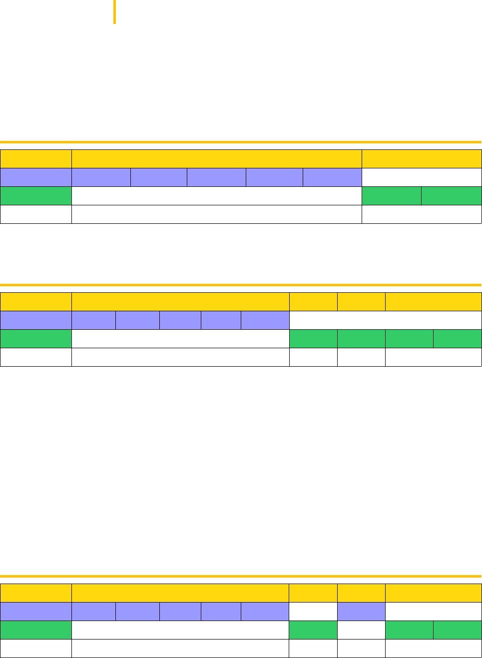
Case 1: ISO None Data Exchange
Command Status words
Host Class Ins. P1 P2 P3
Coupler SW1 SW2
nb. bytes 5 bytes 2 bytes
Case 2 : ISO Out Data Exchange - Coupler ð Host
Command Ack. Data Status words
Host Class Ins. P1 P2 P3
Coupler = Ins. Data SW1 SW2
Nb bytes 5 1 =P3 2
Class : always 80h
•Instruction : command code
•P1 & P2 : command parameters
•P3: number of data bytes expected from the coupler
Ack. : coupler acknowledgement. It is always equal to the command code, except when an error occurs. If
the Acknoledgement value is different than the instruction byte, then the received byte is the first byte of a
status error code coded on 2 bytes.
Data : data sent to the host by the coupler. Size of the command has to be P3.
Status word : 90 00h if correct, error code.
Case 3: ISO In Data Exchange - Host ð Coupler
Command Ack. Data Status words
Host Class Ins. P1 P2 P3 Data
Coupler = Ins. SW1 SW2
Nb bytes 5 1 =P3 2
Couplers - Reference Manuel V1.3

Page 6
•Class : always 80h
•Instruction : command code
•P1 & P2 : command parameters
•P3: number of data bytes sent to the coupler.
•Ack. : coupler acknowledgement. It is always equal to the command code, except when an error
occurs. If Acknowledgement value is different than instruction byte, then the received byte is the first
byte of a status error code coded on 2 bytes.
•Data : data sent by host to the coupler. Size of data array has to be P3.
•Status word : 90 00h if correct / error code.
•Error : If the Acknowledgement value is different than the instruction byte, then the received byte is the
first byte of a status error code coded on 2 bytes.
Case 4 : ISO InOut Data Exchange - Host Û coupler
Command Ack. Data In Ack. Data out Status words
Host Cla. Ins. P1 P2 P3 Data In
Coupler =Ins. =Ins. Data out SW1 SW2
Nb bytes 5 1 = P3 1 = P2 2
Class : always 80h
Instruction : command code
P1 : command parameters
P2 : number of data bytes expected from the coupler.
P3 : number of data bytes sent to the coupler.
Ack. : coupler acknowledgement. It is always equal to the command code, except when an error occurs. If
Acknowledgement value is different than instruction byte, then the received byte is the first byte of a status
error code coded on 2 bytes.
Data : data sent to the host by the coupler. Size of the command has to be P3.
Status word : 90 00h if correct / error code.
Couplers - Reference Manuel V1.3

Page 7
Coupler's command
overview
Common functions
Command INS Description
SELECT_CARD ‘A4h’ Selects one contactless card following list of possible
cards in the field
SELECT_PAGE ‘A6h’ Selects a page in a multi-application chip
TRANSMIT ‘C2h’ Sends and retrieve data from chip through contactless
interface : Transparent mode
GET_RESPONSE ‘C0h’ Reads the internal buffer of the coupler to retrieve chip
answer for ISO 7816 T=0 protocol.
Command INS Description
READ_STATUS ‘F2h’ Reads coupler status or EEPROM memory.
SET_STATUS ‘F4h’ Sets the coupler status or write in EEPROM memory.
DISABLE_COUPLER ‘ADh’ Disables the coupler. it will only respond after a
ENABLE_COUPLER command.
ENABLE_COUPLER ‘AEh’ Enable the coupler. It wakes up the coupler after a
DISABLE_COUPLER command.
Security module functions
Command INS Description
LOAD_KEY_FILE ‘D8h’ Load new master keys for authentication purposes.
ASK_RANDOM ‘84h’ Ask for a random number from the coupler.
SELECT_CURRENT_KEY ‘52h’ Select the key to be used for authentication purposes.
Couplers - Reference Manuel V1.3

Page 8
SELECT CARD
Use
Select a card in order to get the serial number. This command manages anti-collision and authentication
features.
This command is able to test several communication protocol. It answers the number of protocol used to select
the card.
Prototyping
•Command sent : A4h
•Command type : ISO out
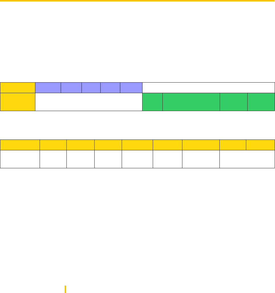
Host 80h A4h P1 P2 P3
Coupler A4h Serial Number 90h 00h
Parameters
Bit 7 6 5 4 3 2 1 0
Function - - Key Auth Presel. Loop Halt Wait
P1: Parameter used for contactless configuration
Important note: ‘ – ‘ are reserved for future use, and values should be set to 0.
WAIT :
1: Wait until a card is selected or a character received from the host (e.g. PC).
0: Exit if no card is detected after 3 attempts.
Note: When SELECT_CARD uses the option «LOOP», the coupler sends ACK=60h
(See T=0 specifications) after each unsuccessful selection until a card is selected.
When a card is selected, «90h 00h» is returned. In order to stop this scanning,
host has to send a byte through the RS232 interface.
HALT:
1: Halts card after selection for fast serial numbers capture.
0: No halt after selection.
LOOP:
1: returned a frame composed of ACK | CARD TYPE | SN | 9000h or wait character 60h
0: no loop performed.
Couplers - Reference Manuel V1.3

Page 9
PRE:
1: Increases pre-selection with INSIDE CONTACTLESS anti-collision and a large number of cards.
0: Standard anti-collision (best for 5 cards max.).
AUTH:
1: Performs a standard INSIDE authentication.
Authentication is performed if the key is set as the current key.
Please refer to appendix A : «How to low a key» for key loading and key management operations
details.
0: Does not perform an authentication.
KEY:
1: Authenticates with Debit Key (Kd = Key 1) if AUTH is set.
0: Authenticates with Credit Key (Kc = Key 2) if AUTH is set.
P2: Parameter used for selecting the card types to be read
B7-b4 B3 B2 B1 b0
0 Protocol 3 Protocol 2 Protocol 1 Protocol 0
INSIDE couplers manage the following protocols :
•Protocol 0 : ISO 14 443 type B & Inside anticollision (only for INSIDE chip)
•Protocol 1 : ISO 15 693 & Inside anticollision (only for INSIDE chip)
•Protocol 2 : ISO 14 443 type B-3
•Protocol 3 : User defined protocol - see «Other ISO chip management» chapter for more information
about Protocol 3 use.
If bit related to protocol x is set to one, coupler will run an anticollision using this protocol.
If several protocols are selected, coupler will test all of them, starting from protocol 0 to protocol 3.
P3: Number of bytes to be return by the coupler
Set P3 = 09h for reading Pico Family Chips serial numbers.
Response: Card type (1 byte) and serial number (8 bytes)
Card type is the protocol number used by the card that has been selected for its answer.
For 15 693 INSIDE’s chips, card type value is 1 as protocol 1 is used for selection. This value is the one to use
to indicate protocol in the transmit command.
Couplers - Reference Manuel V1.3
Page 10
SELECT PAGE
Use
This command is used to select and authenticate in an INSIDE multi-application chip (8*2Ks...).
Prototyping
•Command sent : A6h
•Command type : ISO Out
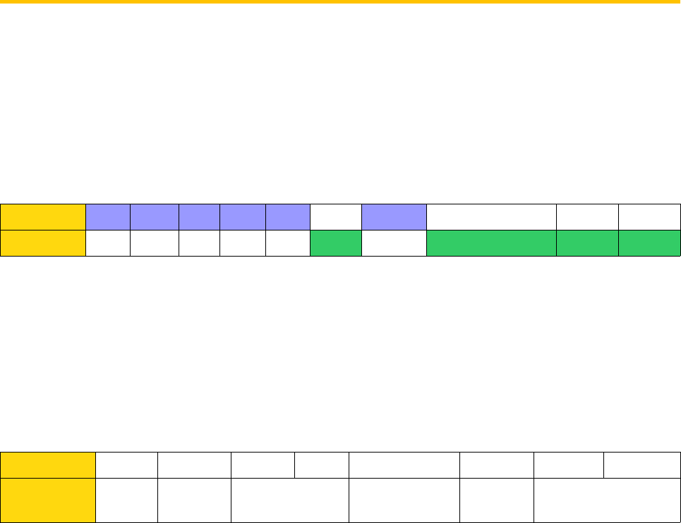
Host 80h A6h P1 P2 08h Data
Coupler A6h Chip's configuration
block
90h 00h
Parameters
Bit 7 6 5 4 3 2 1 0
Function - - - - Auth Page
Selection
Protocol type
P1: Parameter used for contactless configuration
b3 : Auth
0 - Does not perform authentication after PAGESEL.
1 - Performs authentication after PAGESEL
b2: Select Page
0 - Does not send the PAGESEL command before authentication
1 - Sends the PAGESEL command with page contained in P2 before authentication
Note : b2=b3=0 imply that no operation is performed
b1-b0: Protocol type.
This command can only work with PICO family chips
Couplers - Reference Manuel V1.3

Page 11
Contactless Communication Protocol
00 ISO14 443 B PICO family chips
01 ISO15 693 PICO family chips
10 ISO14 443 B-3
11 User’s protocol
Couplers - Reference Manuel V1.3

Page 12
P2 : Page number to select and authenticate and cryptographic key to use
Bit 7 6 5 4 3 2 1 0
Function Reader key number - Page number
b7-b4 : Reader key number
This is the reader key number to use during authentication. The reader will use this key number
(EEPROM) to diversify and authenticate the requested page with Kd or Kc.
Note : 0 correspond to Kd0, 1 to Kc0, …, 14 to Kd7 and 15 to Kc7.
b3 : Page’s key to use to perform the authentication
0 : authentication will be performed with page’s debit key.
1 : authentication will be performed with page’s credit key.
b2-b0 : Page number to select
P3 : Chip answer length
This parameter has to be set to 8 as the chip answers the page’s configuration block (8 bytes).
Couplers - Reference Manuel V1.3
Page 13
TRANSMIT
Use
Transmits data from the coupler to the chip and read back chip response.
This command is the one to use to read and write data in the chip.
Prototyping
•Command sent : C2h
•Command type : ISO In / Out
Host 80h C2h P1 P2 P3 Data
Coupler C2h Chip answer 90h 00h
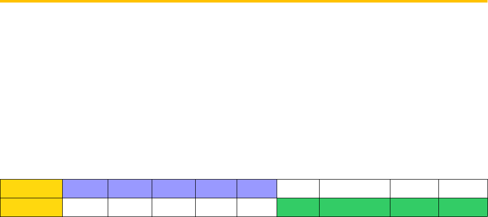
P1 : Defines the contactless communication protocol
P2 : Chip answer length
P3 : Chip command and data
Parameters
P1: Parameter used for contactless configuration
Bit 7 6 5 4 3 2 1 0
Function Send
CRC
Check
CRC
Time out Send signature ISO type RF protocol type
b7: Send CRC
1: The coupler automatically sends the CRC (function of the Data bytes) to the chip. Coupler uses the CRC
associated to the choosen protocol (bit 1 & 0)
0: Only P3 data bytes are sent.
b6: Compare CRC
1: Compares the returned CRC with the expected value calculated by the coupler (verify the data sent by
the chip).
0: CRC is not checked.
b5-b4: Time Out
The time out value depends of the protocol used (b1 and b0 values).
The time out is the time from the command’s EOF (End Of Frame) to the chip response SOF (Start of
Frame).
Couplers - Reference Manuel V1.3

Page 14
Bits 4 & 5 Time-out 15 693 Time-out 14 443
00 800 µs 200 µs
01 4 ms 1 ms
10 24 ms 6 ms
11 40 ms 10 ms
b3: Send Signature:
1: Send a cryptographic signature calculated thanks to the coupler security module. This option may be
used only for UPDATE command performed on secure PICO family chip. Set this value to 0 for non
secure chip or any other manufacturer chips
0: Cryptographic signature is not sent.
b2 : HOST - COUPLER protocol type
1 : Communication is ISO IN-OUT. Coupler send back the data as soon as it receives chip answer.
0 : Commucation between HOST and coupler follows the ISO 78-16 T=0 protocol. Thus TRANSMIT
command is only ISO IN, and user has to use the GET REPONSE command to retrieve chip DATA from
the coupler.
b1-b0: Protocol type
Defines the contactless communication protocol number to be used. When coupler’s EEPROM is set
with the default values, the protocol types are as follows:
Contactless Communication Protocol
0 ISO14 443 B PICO family chips
1 ISO15 693 PICO family chips
10 ISO14 443 B-3
11 User protocol (default value : ISO 14 443 A-3)
P2 : Number of data bytes received from the chip after transmission of the command
If the Compare CRC bit of P1 is enabled, P2 should not include the CRC bytes.
Note: P2<=35 (23h).
P3 : Number of bytes in the data field of the command
If the Send CRC or the Send Signature bit of P1 is enabled, P3 should not include the CRC bytes or the
signature.
Note: P3<=32 (20h).
Couplers - Reference Manuel V1.3
Page 15
Data: Commands and data to send to the chip
All PICOTAG commands are detailed in PICOTAG datasheet.
Response:
•Chip answer
•Status word.
Couplers - Reference Manuel V1.3
Page 16
GET RESPONSE
Use
This command returns the value contained in the internal buffer of the coupler.
It has to be used to get chip answer when the TRANSMIT command is used with the ISO IN type to retreive the
chip answer.
Prototyping
•Command sent :C0h
•Command type : ISO out
Host 80h C0h 00h 00h P3
Coupler C0h Coupler buffer 90h 00h
Parameters
P3: Number of bytes of the coupler response
It has to be less than 35 (23h).
Response : Coupler’s buffer and status words
Couplers - Reference Manuel V1.3

Page 17
READ STATUS
Use
This command is used to get coupler parameters (communication speed…).
Prototyping
•Command sent : F2h
•Command type : ISO out
Host 80h F2h P1 P2 01h
Coupler F2h Read bytes 90h 00h
Parameters
P1: type of parameter to read
B7-b2 B1-b0
0 (RFU) Parameter
b1-b0 : Parameter location
•00 : Parameter value is read in coupler’s EEPROM (setting when power on)
•01 : Coupler’s I/O
•10 : Reserved for Future Use
•11 : Parameter value is read in coupler’s RAM (current setting)
P2: set the parameter address to read
Valid values for P2 according to P1 value:
•EEPROM: 00h to FFh.
•I/O: 05h and 07h.
•Parameter: 50h to 6Fh.
Response : byte value at the transmitted address + status word
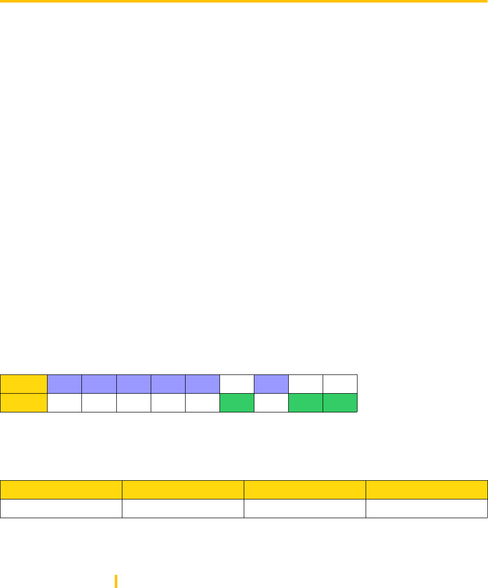
Note: When reading the I/O, the Read byte returned indicates the IN1, OUT1, OUT2 pin states as follows:
(OUT2P is connected to VDD via a 1kW - resistor).
I/O Address B7 B6 B5 B4 B3 B2 B1 B0
05h : output - - - - OUT2 OUT1 - -
07h : Input - - - - - - - IN
Couplers - Reference Manuel V1.3
Page 18
SET STATUS
Use
This command sets configuration parameters and coupler’s I/O :
•Communication speed
•Protocols
•State at Power ON
•2 outputs & 1 input
The various parameters and data used by INSIDE couplers are stored in the EEPROM.
When coupler is powered on, a part of these parameters are load in coupler’s RAM, so that parameters may
be modified in coupler’s EEPROM and in coupler’s RAM.
For a given parameter, RAM and EEPROM address are the same. For example, speed parameter is located at
address 6Dh for both RAM and EEPROM.
✔When updating a value in the coupler’s EEPROM, this value will be the default value after turning the
coupler on.
✔When updating a value in the coupler’s RAM, this value will be the current value until the next Power Off.
✔When writing to EEPROM occurs, EEPROM parameters are reloaded into processor memory (RAM).
Prototyping
•Command sent : F4h
•Command type : ISO In
Host 80h F4h P1 P2 01h Data
Coupler F4h 90h 00h
Parameters
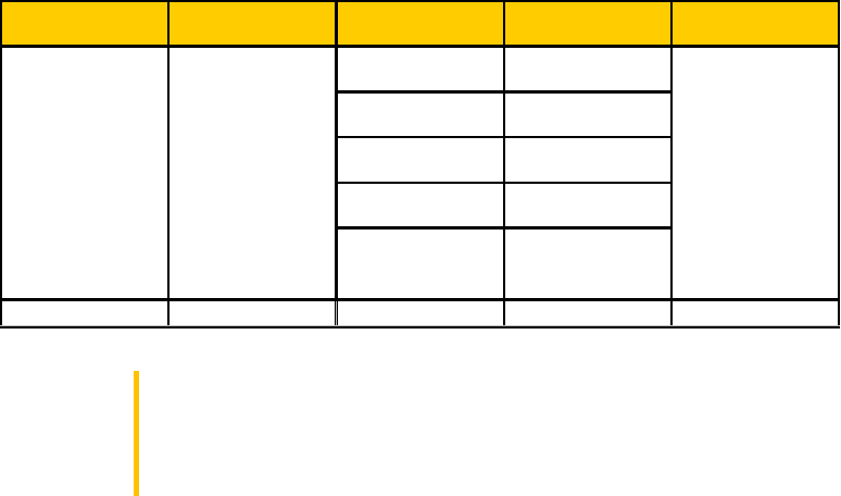
P1: Sets the type of configuration parameter to update
B7 B6 B5-b2 B1-b0
Reset coupler Reset magnetic field - (RFU) Address
b7 : Resets coupler
if this bit is set to 1, coupler will fully reload EEPROM in RAM as if the coupler is powered on.
Note : when b7 = 1, the coupler responds 3Bh 00h.
b6 : Reset magnetic field
Magnetic field is cut for 20 ms.
When this bit is set to 1, coupler will execute no other action, including EEPROM or RAM update.
Couplers - Reference Manuel V1.3
Page 19
b5-b2 : RFU (reserved for future use)
b1-b0 : Parameter location
00 : Parameter value is read in coupler’s EEPROM (setting when power on)
01 : Coupler’s I/O
10 : Reserved for Future Use
11 : Parameter value is read in coupler’s RAM (current setting)
P2: Sets the parameter address to update
Valid values for P2 according to P1 value:
•EEPROM : 00h to 07h and 3Eh to FFh.
•I/O : 05h, 06h, 07h.
•RAM : 50h to 6Fh.
Response: Status words
Modifiable parameters
User can change the following parameters in coupler’s memory :
•Protocols - Please refer to «Managing ISO protocol with INSIDE coupler» application note for more
information about protocol management
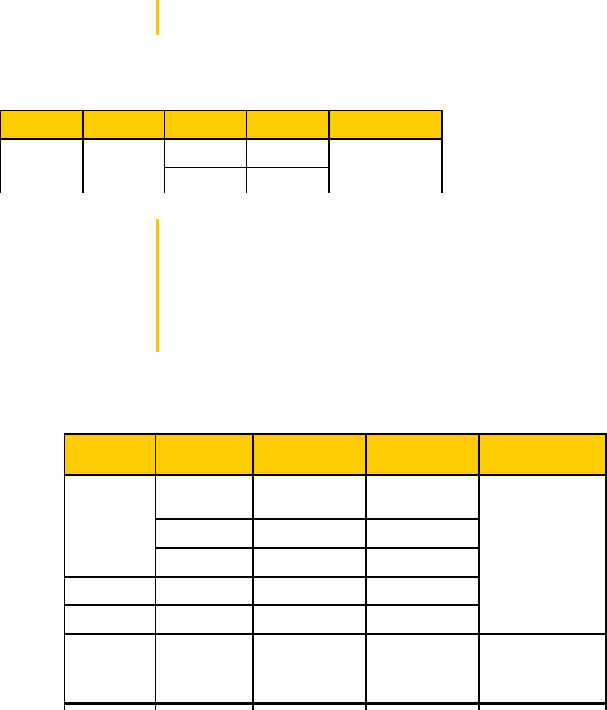
•Serial communication speed - from 9600 to 424000 bauds depending on the reader
Note : When updating the COMSPEED parameter, the coupler returns the Status
Words with the previous COMSPEED before the COMSPEED update.
Example : the baudrate is set to 9600 bauds and needs to be temporarily updated
to 115 200 bauds.
Couplers - Reference Manuel V1.3
Name Address State Hex. value Available on...
9600 57h
19200 2Dh
38400 15h
57600 0Eh
115200 06h
Serial
communication
speed
6Dh
All readers
Page 20
Send a SET_STATUS command (80h F4h 03h 6Dh 01h & 06h). The coupler
responds (Status words) using 9600 bauds.
State at power on - Is coupler emitting a field when it is powered on ? (please refer to ENABLE and DISABLE
command chapters)
Note : The ACTIVATE AT POWER ON parameter defines the state of the coupler
when you turn it on. If you turn the coupler on and if 00h is written in the EEPROM
at address 42h , it will be «asleep» until you send an ENABLE_COUPLER
command.
IMPORTANT NOTE : If change in the EEPROM is followed by a reset of the
coupler and if address 42h contains 00h then the coupler will be asleep until you
send an ENABLE command.
Coupler's INPUTS and OUTPUTS
Please refer to chapter 1 for connection.
EEPROM free area
User can use EEPROM bytes from 70h to 7Dh to write some data.
Couplers - Reference Manuel V1.3
Name Address State Hex. value Available on...
Enable 01h
Disable 00h
All reader
42h
State at
power on
Reader Input / Output I/O address Command to
use Value
OUT1 05h - Bit 1 Set Status
OUT 2 05h - bit 2 Set Status
IN 1 07h - bit 0 Read Status
M22xH OUT 05h - bit 2 Set Status
M302H OUT 06h - bit 4 Set Status
Byte value & color
04h : Red
08h : Orange
0Ch : Green
Bit at 0 : low level
Bit at 1 : High level
M21xH
Set Status
05h
LED
ACCESSO

Page 21
DISABLE COUPLER
Use
The coupler goes in SLEEP mode that allows low power consumption and RF carrier is desactivated.
After this command, the coupler will not respond to any command except the ENABLE_COUPLER command.
A new feature available only on M21xH 2G is that coupler can detect if a card approach the antenna and
wake up on its own.
Prototyping
Command sent : ADh
Command Type : ISO none
Parameters
Response: Status words
Note : It is possible using the SET_STATUS command to have the coupler in a sleep
mode each time it turns on. The coupler will then be asleep until you send an
ENABLE_COMMAND. Please refer to the SET_STATUS command for activating this
feature.
Couplers - Reference Manuel V1.3
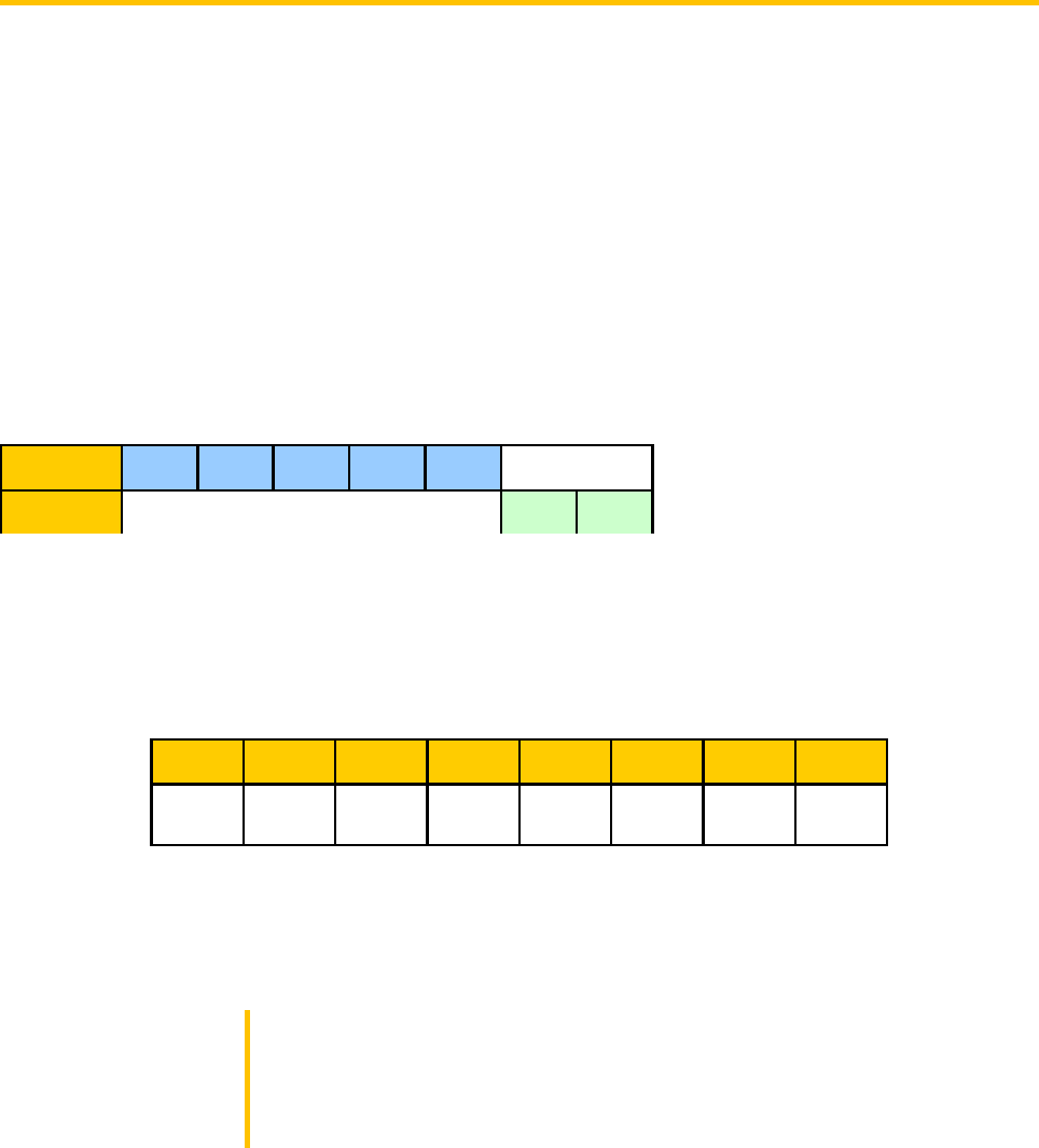
Host 80h ADh BCh DAh 01h
Coupler 90h 00h
Page 22
DISABLE COUPLER ENHANCED
Use
As the DISABLE_COUPLER command, this specific version enables the user to asleep the reader.
But M210H 2G and M260H 2G have the possibility to detect that a card approaches their antenna.
As sooon as the card is detected, the coupler will turn the RF field on, and start a card selection.
If no card answers to the anticollision process, the coupler go back asleep. If a card is selected, then the
coupler stay awake.
Prototyping
Command sent : ADh
Command Type : ISO none
Parameters
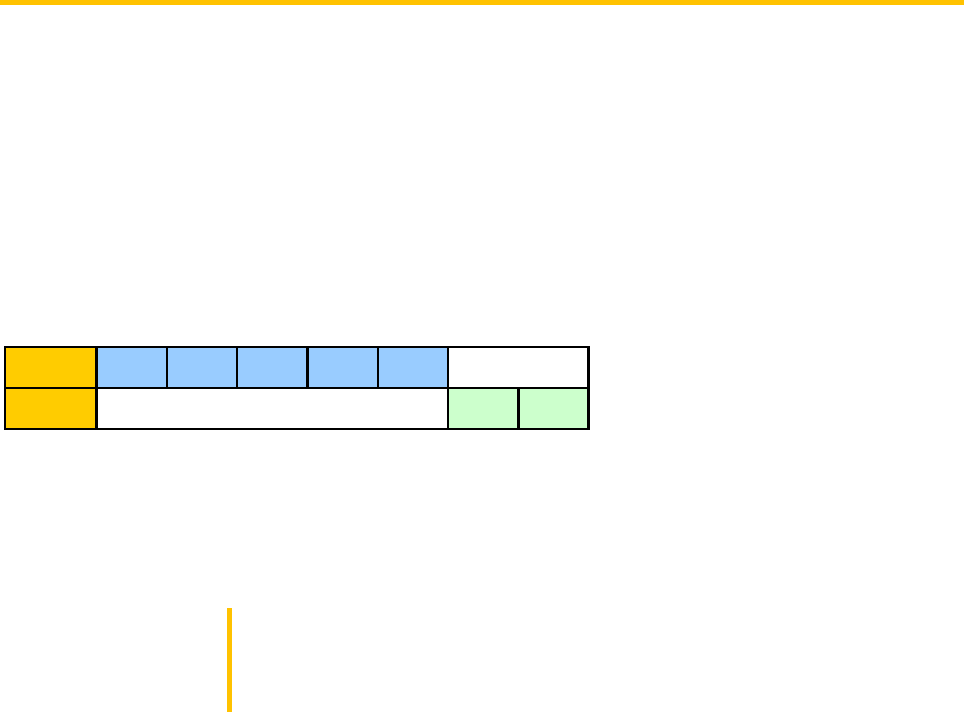
P2 : specify the anticollision to process when a card is detected. If several bit are set at 1, all selected
anticollision will be performed.
If « Ant x » bit is set, then the anti-collision x will be processed else not.
If no « Ant x » is set, then the coupler will wake-up only by detecting a field change over the reader.
If b4 is set, then the OUT1 PIN is set to high for 10 ms when a card is selected.
Note 1 : It is possible using the SET_STATUS command to have the coupler in a
sleep mode each time it turns on. The coupler will then be asleep until you send
an ENABLE_COMMAND. Please refer to the SET_STATUS command for
activating this feature.
Note 2 : This command is only available on M210-2G and ACCESSO-2G.
Couplers - Reference Manuel V1.3
Host 80h ADh BCh P2 01h
Coupler 90h 00h
b7 b6 b5 b4 b3 b2 b1 b0
- 0 -
Pulse
OUT1
Ant3 Ant2 Ant1 Ant0
Page 23
ENABLE COUPLER
Use
This command restores a normal coupler running, with RF emission.
This command can only be used after a DISABLE_COUPLER command or if the coupler is desactivated after
power on.
Prototyping
Command sent : AEh
Command type : ISO none
Parameters
Response : Status words
The coupler will respond «Instruction not recognized» (6Dh 00h) if already activated.
Important note : You have to send the ENABLE_COUPLER command in a window
of 16ms. To be sure that your command will be received, send it twice. The time
between the sending of the 2 commands has to be less than 10 ms.
This is automatically done when using MX.Enable method (ActiveX component).
Couplers - Reference Manuel V1.3
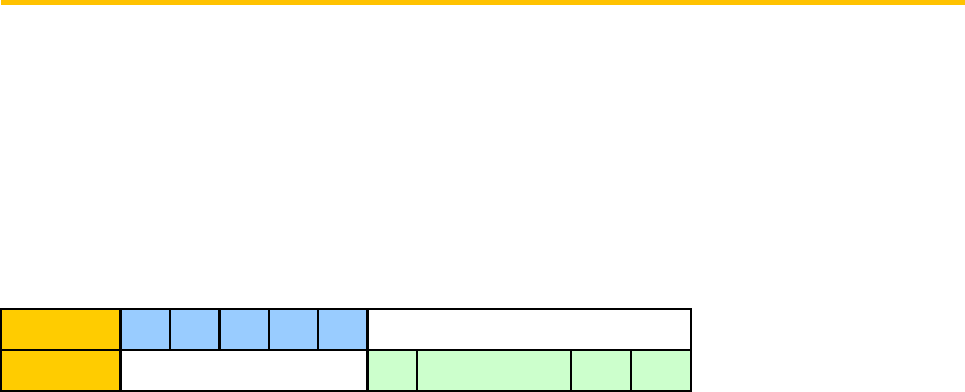
Host 80h AEh DAh BCh 00h
Coupler 3Bh 00h
Page 24
ASK RANDOM
Use
This command returns an 8 bytes random value from the coupler.This command has to be used to initialize the
key loading procedure.
Prototyping
Command sent : 84h
Command type : ISO out
Parameters
Response : Random number; Status words
Couplers - Reference Manuel V1.3
Host 80h 84h 00h 00h 08h
Coupler 84h Random number 90h 00h

Page 25
LOAD KEY FILE
Use
This function loads into the coupler’s security module a key to be used for authentication and security purposes.
Key loading is a security sensitive operation. In order to protect the confidentiality of the keys transferred to the
coupler, data is encrypted. A 4-byte checksum is also sent in order to guarantee the authenticity of the data,
which could be corrupted either through transmission errors or by a deliberate attempt to fraud the system.
Refer to «Coupler’s key loading» chapter for more information about security and the way to calculate
encrypted key and checksum.
Prototype
Command sent : D8h
Command type : ISO In
Parameters
P1 : Parameter used for key operations
00: Load and activate the key pointed by P2.
01: Deactivate the key pointed by P2 (Forbidden option to Exchange Key Ke).
02: Delete the key pointed by P2 (Forbidden option to Exchange Key Ke).
Others value are reserved for future use.
Note :
With the 00 option, this command will replace the old value of the key with the
new value.
With the 01 and 02 options, the command has to be sent with 12-byte data at any
value (Data = XX XX XX XX XX XX XX XX XX XX XX XX).
When a key is deactivated, you need to reload it to reactivate the key.
P2 : Key number
00h - Exchange Key Ke: used for key loading operation.
01h - Debit Key Kd0
02h - Credit Key Kc0
03h - Debit Key Kd1
04h - Credit Key Kc1
.....
0Fh - Debit Key Kd7
Couplers - Reference Manuel V1.3
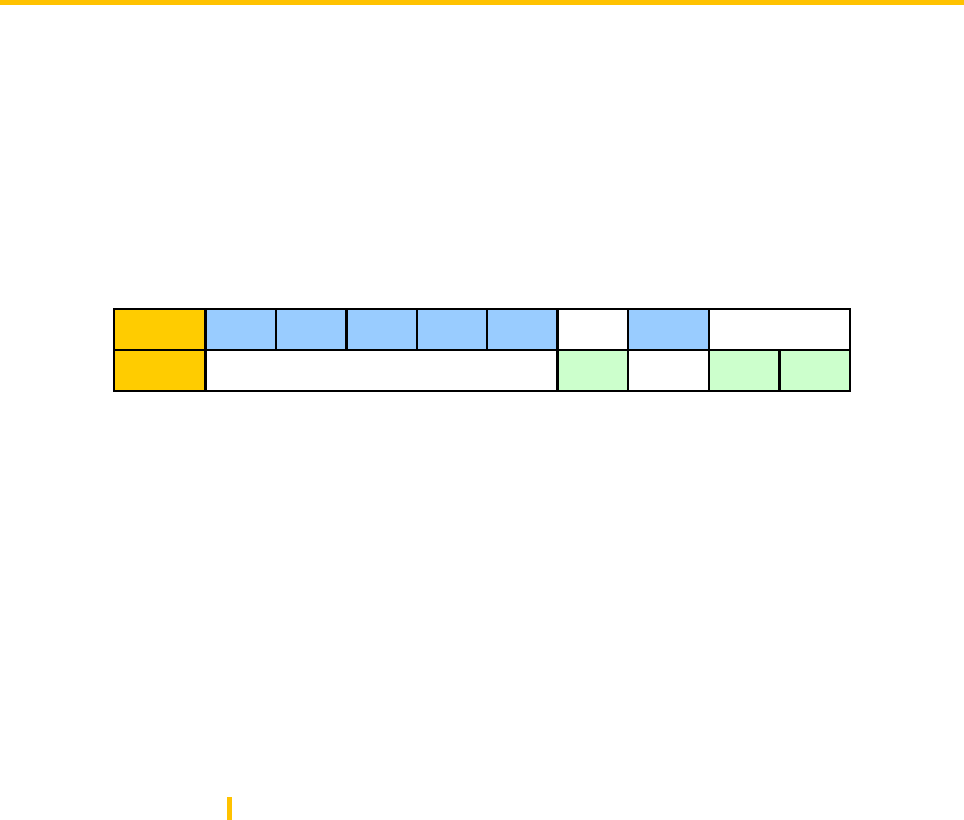
Host 80h D8h P1 P2 OCh Data
Coupler D8h 90h 00h
Page 26
10h - Credit key Kc7
Data
This field contains:
the 8-byte encrypted master key
the 4-byte checksum
Response: Status Words
Couplers - Reference Manuel V1.3
Page 27
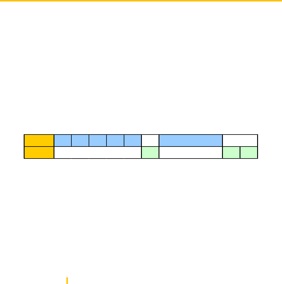
SELECT CURRENT KEY
Use
This function allows to choose a key for future authentications. A key that has been deactivated or deleted
cannot be selected. Only one of the 16 keys can be current at the same time.
Prototype
Command sent : 52h
Command type : ISO In
Parameters
P2 : Key number
01h - Debit Key Kd0
02h - Credit Key Kc0
03h - Debit Key Kd1
04h - Credit Key Kc1
.....
0Fh - Debit Key Kd7
10h - Credit key Kc7
Note : if the specified key is deactivated, the status bytes returned is 6Bh 00h.
Couplers - Reference Manuel V1.3
Host 80h 52h 00h P2h 08h 8 * 00h
Coupler 52h 90h 00h
Page 28
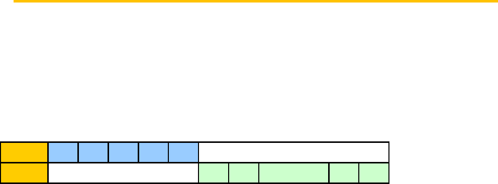
DIVERSIFY KEY
Use
This function enables the user to calculate the result of key diversication with selected chip serial number.
The key diversified value is used for authentication and signature calculation while writing a secure chip.
This can have 2 uses :
- before an authentication (SELECT_PAGE or AUTHENTIFY command)
- to calculate the keys that will be written in a chip during a personalization phase (only working with a
dedicated personalization coupler)
Prototype
•Command sent : 52h
•Command type : ISO In
Parameters
P2 : Key number
01h - Debit Key Kd0
02h - Credit Key Kc0
03h - Debit Key Kd1
04h - Credit Key Kc1
.....
0Fh - Debit Key Kd7
10h - Credit key Kc7
Note : if the specified key is deactivated, the status bytes returned is 6Bh 00h.
Couplers - Reference Manuel V1.3
Host 80h 52h 00h P2h 08h Chip serial number
Coupler 52h 90h 00h
Page 29
GET CONFIG
Use
This command is used to read the ID of the MCU part.
Prototype
Command sent : CAh
Command type : ISO In
Parameters
Data : MCU part’s ID
Code Info (1 byte) : RFU
Couplers - Reference Manuel V1.3
Host 80h CAh 00h 00h 09h
Coupler CA ID (8) Code Info (1) 90h 00h