Integra Dtr 5 Users Manual
DTR-5.5 to the manual 8f736278-50da-ea84-d9f7-8a13e00eb243
2015-03-12
: Integra Integra-Dtr-5-5-Users-Manual-578395 integra-dtr-5-5-users-manual-578395 integra pdf
Open the PDF directly: View PDF ![]() .
.
Page Count: 96

DTR-6.5/5.5
Instruction Manual
AV Receiver
DTR-6.5,5.5_En.book Page 1 Wednesday, July 28, 2004 9:07 AM
2
Important Safety Instructions
1. Read these instructions.
2. Keep these instructions.
3. Heed all warnings.
4. Follow all instructions.
5. Do not use this apparatus near water.
6. Clean only with dry cloth.
7. Do not block any ventilation openings. Install in
accordance with the manufacturer’s instructions.
8. Do not install near any heat sources such as radia-
tors, heat registers, stoves, or other apparatus
(including amplifiers) that produce heat.
9. Do not defeat the safety purpose of the polarized or
grounding-type plug. A polarized plug has two
blades with one wider than the other. A grounding
type plug has two blades and a third grounding
prong. The wide blade or the third prong are pro-
vided for your safety. If the provided plug does not
fit into your outlet, consult an electrician for
replacement of the obsolete outlet.
10. Protect the power cord from being walked on or
pinched particularly at plugs, convenience recepta-
cles, and the point where they exit from the appara-
tus.
11. Only use attachments/accessories specified by the
manufacturer.
12.
Use only with the cart, stand,
tripod, bracket, or table spec-
ified by the manufacturer, or
sold with the apparatus.
When a cart is used, use cau-
tion when moving the cart/
apparatus combination to
avoid injury from tip-over.
13. Unplug this apparatus during lightning storms or
when unused for long periods of time.
14. Refer all servicing to qualified service personnel.
Servicing is required when the apparatus has been
damaged in any way, such as power-supply cord or
plug is damaged, liquid has been spilled or objects
have fallen into the apparatus, the apparatus has
been exposed to rain or moisture, does not operate
normally, or has been dropped.
15. Damage Requiring Service
Unplug the apparatus from the wall outlet and refer
servicing to qualified service personnel under the
following conditions:
A. When the power-supply cord or plug is damaged,
B. If liquid has been spilled, or objects have fallen
into the apparatus,
C. If the apparatus has been exposed to rain or
water,
D. If the apparatus does not operate normally by
following the operating instructions. Adjust only
those controls that are covered by the operating
instructions as an improper adjustment of other
controls may result in damage and will often
require extensive work by a qualified technician
to restore the apparatus to its normal operation,
E. If the apparatus has been dropped or damaged in
any way, and
F. When the apparatus exhibits a distinct change in
performance this indicates a need for service.
16. Object and Liquid Entry
Never push objects of any kind into the apparatus
through openings as they may touch dangerous volt-
age points or short-out parts that could result in a
fire or electric shock.
The apparatus shall not be exposed to dripping or
splashing and no objects filled with liquids, such as
vases shall be placed on the apparatus.
Don’t put candles or other burning objects on top of
this unit.
17. Batteries
Always consider the environmental issues and fol-
low local regulations when disposing of batteries.
18. If you install the apparatus in a built-in installation,
such as a bookcase or rack, ensure that there is ade-
quate ventilation.
Leave 20 cm (8") of free space at the top and sides
and 10 cm (4") at the rear. The rear edge of the shelf
or board above the apparatus shall be set 10 cm (4")
away from the rear panel or wall, creating a flue-like
gap for warm air to escape.
WARNING:
TO REDUCE THE RISK OF FIRE OR ELECTRIC
SHOCK, DO NOT EXPOSE THIS APPARATUS
TO RAIN OR MOISTURE.
CAUTION:
TO REDUCE THE RISK OF ELECTRIC SHOCK,
DO NOT REMOVE COVER (OR BACK). NO
USER-SERVICEABLE PARTS INSIDE. REFER
SERVICING TO QUALIFIED SERVICE
PERSONNEL.
The lightning flash with arrowhead symbol, within an
equilateral triangle, is intended to alert the user to the
presence of uninsulated “dangerous voltage” within
the product’s enclosure that may be of sufficient
magnitude to constitute a risk of electric shock to
persons.
The exclamation point within an equilateral triangle is
intended to alert the user to the presence of important
operating and maintenance (servicing) instructions in
the literature accompanying the appliance.
WARNING
RISK OF ELECTRIC SHOCK
DO NOT OPEN
RISQUE DE CHOC ELECTRIQUE
NE PAS
OUVRIR
AVIS
PORTABLE CART WARNING
S3125A
DTR-6.5,5.5_En.book Page 2 Wednesday, July 28, 2004 9:07 AM

3
Precautions
For U.S. Models
Note to CATV system installer:
This reminder is provided to call the CATV system
installer’s attention to Section 820-40 of the NEC which
provides guidelines for proper grounding and, in partic-
ular, specifies that the cable ground shall be connected
to the grounding system of the building, as close to the
point of cable entry as practical.
FCC Information for User
CAUTION:
The user changes or modifications not expressly
approved by the party responsible for compliance could
void the user’s authority to operate the equipment.
NOTE:
This equipment has been tested and found to comply
with the limits for a Class B digital device, pursuant to
Part 15 of the FCC Rules.
These limits are designed to provide reasonable protec-
tion against harmful interference in a residential instal-
lation. This equipment generates, uses and can radiate
radio frequency energy and, if not installed and used in
accordance with the instructions, may cause harmful
interference to radio communications. However, there is
no guarantee that interference will not occur in a partic-
ular installation.
If this equipment does cause harmful interference to
radio or television reception, which can be determined
by turning the equipment off and on, the user is encour-
aged to try to correct the interference by one or more of
the following measures:
• Reorient or relocate the receiving antenna.
• Increase the separation between the equipment and receiver.
•Connect the equipment into an outlet on a circuit different from
that to which the receiver is connected.
• Consult the dealer or an experienced radio/TV technician
for help.
For Canadian model
NOTE:
THIS CLASS B DIGITAL APPARATUS
COMPLIES WITH CANADIAN ICES-003.
For models having a power cord with a polarized plug:
CAUTION:
TO PREVENT ELECTRIC SHOCK,
MATCH WIDE BLADE OF PLUG TO WIDE SLOT,
FULLY INSERT.
Modèle pour les Canadien
REMARQUE:
CET APPAREIL NUMÉRIQUE DE
LA CLASSE B EST CONFORME À LA NORME
NMB-003 DU CANADA.
Sur les modèles dont la fiche est polarisée:
ATTENTION:
POUR ÉVITER LES CHOCS ÉLEC-
TRIQUES, INTRODUIRE LA LAME LA PLUS
LARGE DE LA FICHE DANS LA BORNE CORRE-
SPONDANTE DE LA PRISE ET POUSSER
JUSQU’AU FOND.
1. Recording Copyright
—Unless it’s for personal use
only, recording copyrighted material is illegal with-
out permission of the copyright holder.
2. AC Fuse
— The AC fuse inside the AV receiver is
not user-serviceable. If you cannot turn on the AV
receiver, have it checked by the dealer from whom
you purchased this unit.
3. Care
—Occasionally you should dust the AV
receiver all over with a soft cloth. For stubborn
stains, use a soft cloth dampened with a weak solu-
tion of mild detergent and water. Dry the AV
receiver immediately afterwards with a clean cloth.
Don’t use abrasive cloths, thinners, alcohol, or other
chemical solvents, because they may damage the
finish or remove the panel lettering.
4. Power
WARNING
BEFORE PLUGGING IN THE UNIT FOR THE
FIRST TIME, READ THE FOLLOWING SECTION
CAREFULLY.
AC outlet voltages vary from country to country. Make
sure that the voltage in your area meets the voltage
requirements printed on the AV receiver’s rear panel
(e.g., AC 230 V, 50 Hz or AC 120 V, 60 Hz).
Setting the [Standby/On] switch to Standby does not
fully shutdown the AV receiver. If you do not intend to
use the AV receiver for an extended period, remove the
power cord from the wall outlet.
Thank you for purchasing an Integra AV
Receiver.
Please read this manual thoroughly before
making any connections and plugging it in.
Following the instructions in this manual will
enable you to obtain optimum perfor-
mance and listening enjoyment from your
new AV Receiver.
Please retain this manual for future refer-
ence.
DTR-6.5,5.5_En.book Page 3 Wednesday, July 28, 2004 9:07 AM
4
Precautions
—Continued
For British models
Replacement and mounting of an AC plug on the power
supply cord of this unit should be performed only by
qualified service personnel.
IMPORTANT
The wires in the mains lead are coloured in accordance
with the following code:
Blue: Neutral
Brown: Live
As the colours of the wires in the mains lead of this
apparatus may not correspond with the coloured mark-
ings identifying the terminals in your plug, proceed as
follows:
The wire which is coloured blue must be connected to
the terminal which is marked with the letter N or
coloured black.
The wire which is coloured brown must be connected to
the terminal which is marked with the letter L or
coloured red.
IMPORTANT
A 5 or 13 ampere fuse is fitted in this plug. Should the
fuse need to be replaced, please ensure that the replace-
ment fuse has a rating of 5 or 13 amperes and that it is
approved by ASTA or BSI to BS1362. Check for the
ASTA mark or the BSI mark on the body of the fuse.
IF THE FITTED MOULDED PLUG IS UNSUITABLE
FOR THE SOCKET OUTLET IN YOUR HOME
THEN THE FUSE SHOULD BE REMOVED AND
THE PLUG CUT OFF AND DISPOSED OF SAFELY.
THERE IS A DANGER OF SEVERE ELECTRICAL
SHOCK IF THE CUT OFF PLUG IS INSERTED
INTO ANY 13 AMPERE SOCKET.
If in any doubt, consult a qualified electrician.
For European Models
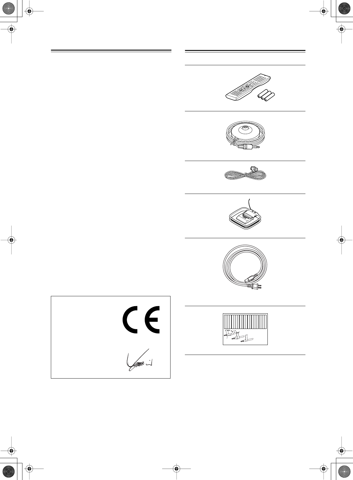
Supplied Accessories
Make sure you have the following accessories:
* In catalogs and on packaging, the letter at the end of the product
name indicates the color. Specifications and operation are the
same regardless of color.
Declaration of Conformity
We, ONKYO EUROPE
ELECTRONICS GmbH
LIEGNITZERSTRASSE 6,
82194 GROEBENZELL,
GERMANY
GROEBENZELL, GERMANY
ONKYO EUROPE ELECTRONICS GmbH
I. MORI
declare in own responsibility, that the ONKYO product
described in this instruction manual is in compliance with the
corresponding technical standards such as EN60065,
EN55013, EN55020 and EN61000-3-2, -3-3.
Remote controller & three batteries (AA/R6)
Speaker setup microphone
Indoor FM antenna
AM loop antenna
Power cord
(Plug type varies from country to country.)
Speaker cable labels
Front
Left
Front
Left
SP-B
/
Zone 2
Left
SP-B
/
Zone 2
Left
Surround
Right
Surround
Right
Surround Back
Right
Surround Back
Right
Zone 2
Right
Zone 2
Right
Front
Left
Front
Left
SP-B
/
Zone 2
Left
SP-B
/
Zone 2
Left
Front
Right
Front
Right
SP-B
/
Zone 2
Right
SP-B
/
Zone 2
Right
Front
Right
Front
Right
SP-B
/
Zone 2
Right
SP-B
/
Zone 2
Right
Surround
Right
Surround
Right
Center
Center
Center
Center
Surround
Left
Surround
Left
Surround
Left
Surround
Left
Surround Back
Right
Surround Back
Right
Zone 2
Right
Zone 2
Right
Surround Back
Left
Surround Back
Left
Zone 2
Left
Zone 2
Left
Surround Back
Left
Surround Back
Left
Zone 2
Left
Zone 2
Left
12
3
Speaker Cable
DTR-6.5,5.5_En.book Page 4 Wednesday, July 28, 2004 9:07 AM
5
Features
Amplifier
• 7-channel amplifier
• Optimum Gain Volume Circuitry
• Zone 2 capability
• 24-bit/192 kHz D/A converters
• WRAT (Wide Range Amplifier Technology)
• Color-coded speaker terminal posts
Audio/Video
• Dolby
*1
Digital, Dolby Digital EX, Dolby Pro
Logic IIx
• DTS
*2
, DTS-ES Discrete, DTS-ES Matrix, DTS
Neo:6, and DTS 96/24
• Theater-Dimensional
*3
virtual surround mode
• VLSC (Vector Linear Shaping Circuitry) on all chan-
nels
• Zone 2 out
• Composite video to S-Video and S-Video to compos-
ite video conversion
• Composite and S-Video to component video conver-
sion
•3 component video inputs, 1 output
•5 S-Video inputs, 3 outputs
FM/AM Tuner
•40 AM/FM presets
• AM/FM auto tuning
Others
• Includes microphone for automatic speaker setup
• Easy-to-use onscreen setup menus
• Preprogrammed remote controller for use with other
AV components
Amplifier
• 100 watts per channel into 8 ohms, 20 Hz to 20 kHz,
less than 0.08% total harmonic distortion (FTC rating)
Audio/Video
• THX
*4
Surround EX
• THX Select certified
• Re-EQ
•Pre outs for front L/R, center, surround L/R, surround
back L/R, and subwoofer
•7 digital inputs (5 optical, 2 coaxial), 2 digital outputs
(1 optical, 1 coaxial)
Amplifier
• 85 watts per channel into 8 ohms, 20 Hz to 20 kHz,
less than 0.08% total harmonic distortion (FTC rating)
Audio/Video
• CinemaFILTER
*5
• Subwoofer pre out
•6 digital inputs (4 optical, 2 coaxial), 1 digital optical
output.
DTR-6.5/5.5
*1. Manufactured under license from Dolby Laboratories.
“Dolby”, “Pro Logic”, “Surround EX”, and the double-D sym-
bol are trademarks of Dolby Laboratories.
*2. “DTS”, “DTS 96/24”, “DTS-ES”, and “Neo:6” are trademarks
of Digital Theater Systems, Inc.
*3. “Theater-Dimensional” is a trademark of Onkyo Corporation.
DTR-6.5
*4. “THX” is a trademark or registered trademark of THX Ltd.
“Surround EX” is a trademark of Dolby Laboratories. Used
under authorization. All rights reserved.
THX Select
Before any home theater component can be THX Select
certified, it must pass a rigorous series of quality and
performance tests. Only then can a product feature the
THX Select logo, which is your guarantee that the
Home Theater products you purchase will give you
superb performance for many years to come. THX
Select requirements define hundreds of parameters,
including power amplifier performance, and pre-ampli-
fier performance and operation for both digital and ana-
log domains. THX Select receivers also feature
proprietary THX technologies (e.g., THX Mode) which
accurately translate movie soundtracks for home the-
ater playback.
DTR-5.5
*5. “CinemaFILTER” is a trademark of Onkyo Corporation.
“Xantech” is a registered trademark of Xantech Corporation.
“Niles” is a registered trademark of Niles Audio Corporation.
DTR-6.5,5.5_En.book Page 5 Wednesday, July 28, 2004 9:07 AM
6
Table of Contents
Basic
Introduction
Important Safety Instructions ..........................................................................................2
Precautions .......................................................................................................................3
Supplied Accessories.......................................................................................................4
Features .............................................................................................................................5
Table of Contents ..............................................................................................................6
Front & Rear Panels..........................................................................................................8
Remote Controller...........................................................................................................13
About Home Theater .......................................................................................................20
Connecting the AV receiver
About AV Connections ...................................................................................................21
Connecting Your Speakers.............................................................................................22
Connecting Antenna.......................................................................................................24
Connecting Both Audio & Video....................................................................................26
Which Connections Should I Use? ...............................................................................26
Connecting Your TV or Projector ...................................................................................27
Connecting AV components ..........................................................................................28
Connecting Audio components.....................................................................................34
Connecting a Power Amplifier (DTR-6.5 only)..............................................................37
Connecting Components ........................................................................................37
Connecting the Power Cords of Other Components...................................................38
Connecting the Supplied Power Cord...........................................................................38
Turning On the AV receiver ............................................................................................38
First Time Setup
Automatic Speaker Setup...............................................................................................39
About the Onscreen Setup Menus ................................................................................41
Initial Setup......................................................................................................................42
Digital Input ...................................................................................................................42
Component Video Setup ...............................................................................................43
Minimum Speaker Impedance (not American models) .................................................44
TV Format Setup (not American models)......................................................................45
Speaker Setup .................................................................................................................46
Changing the TAPE/MD/CDR Display ............................................................................52
Basic Operation
Selecting the Input Source.............................................................................................53
Setting the Display Brightness......................................................................................54
Muting the AV receiver ...................................................................................................54
Using the Sleep Timer.....................................................................................................54
Using Headphones .........................................................................................................54
Displaying Source Information ......................................................................................55
Using the Tuner ...............................................................................................................56
Selecting Listening Modes.............................................................................................58
Listening mode table .....................................................................................................59
About the Listening Modes............................................................................................60
Others
Troubleshooting ..............................................................................................................90
Specifications..................................................................................................................94
DTR-6.5,5.5_En.book Page 6 Wednesday, July 28, 2004 9:07 AM
7
Table of Contents
—Continued
Advanced
Controlling Other Components
Entering a Remote Control Codes................................. 80
Learning Commands from Another Remote
Controller ..................................................................... 88
Using Macros................................................................... 89
Advanced Setup
Decoder Setup................................................................. 66
Adjusting the Bass & Treble........................................... 68
Audio Adjust Functions.................................................. 68
Assigning Listening Modes to Input Sources.............. 70
Setting Preferences ........................................................ 71
Changing the Remote Controller’s ID ........................... 73
Advanced Operation
Using the Late Night Function (Dolby Digital only) ..... 62
Using the Re-EQ Function (DTR-6.5 only) .................... 62
Using the CinemaFILTER (TDR-5.5 only) ...................... 62
Adjusting Individual Speaker Levels............................. 63
Using the DVD Analog Multichannel Input ................... 63
Recording ........................................................................ 64
Zone 2
Connecting Zone 2.......................................................... 74
Setting the Powered Zone 2 ........................................... 75
Setting the zone 2 OUT................................................... 76
Using Zone 2.................................................................... 77
Using the Remote Control in Zone 2............................. 79
Advanced
Features
Advanced
Features
Advanced
Features
Advanced
Features
Introduction ............................... 2
Connections ............................ 21
First Setup ............................... 39
Basic Operation ...................... 53
Advanced Operation ............... 62
Advanced Setup ...................... 66
Zone 2 ...................................... 74
Using the Remote Controller
with Other Components ...... 80
Troubleshooting ...................... 90
Others....................................... 94
DTR-6.5,5.5_En.book Page 7 Wednesday, July 28, 2004 9:07 AM
8
Front & Rear Panels
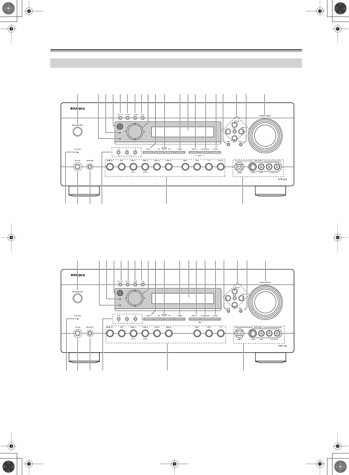
Front Panel
Standby
Zone 2
1
ZYWVU X
5 6 789 J K M N Q TSO P RL2 3 4
Standby
Zone 2
1
ZYWVU X
5 678 J K L N O R TP Q SM2 3 4 9
DTR-6.5
DTR-5.5
DTR-6.5,5.5_En.book Page 8 Wednesday, July 28, 2004 9:07 AM

9
Front & Rear Panels
—Continued
For detailed information, see the pages in parentheses.
A
Standby/On button (38)
This button is used to set the AV receiver to On or
Standby. For models with a POWER switch, this
button has no effect unless the POWER switch is set
to ON.
B
Standby indicator (38)
This indicator lights up when the AV receiver is in
Standby mode, and it flashes while a signal is being
received from the remote controller.
C
Zone 2 indicator (77)
This indicator lights up when Zone 2 is selected.
D
Remote-control sensor (13)
This sensor receives control signals from the remote
controller.
E
Rec Out button (64)
This button is used to select the input source to be
recorded.
F
Zone 2 button (77)
This button is used to select the input source for
Zone 2.
G
Level button (77)
This button is used to set the volume for Zone 2.
H
Tone button (78)
This button is used to adjust the bass and treble for
Zone 2.
I
Controller [ ] [ ] buttons (64, 77, 78)
These buttons are used to select the input source to
be recorded via the REC OUTs, to select the input
source for Zone 2, and to set the volume, bass, and
treble for Zone 2.
J
Stereo button (58)
This button is used to select the Stereo listening
mode.
K
Listening Mode [ ] [ ] buttons (58)
These buttons are used to select the listening modes.
L
Display button (55)
This button is used to display various information
about the currently selected input source.
M
Display
See “Display” on page 10.
N
Memory button (57)
This button is used when storing or deleting radio
presets.
O
Tuning Mode button (56)
This button is used to select the Auto or Manual tun-
ing mode.
P
Dimmer button (54)
This button is used to adjust the display brightness.
Q
Setup button (42)
This button is used to access the onscreen setup
menus that appear on the connected TV.
R
Arrow/Tuning/Preset & Enter buttons (42)
When the AM or FM input source is selected, the
Tuning [ ] [ ] buttons are used to tune the tuner,
and the Preset [ ] [ ] buttons are used to select
radio presets (see page 57). When the onscreen
setup menus are used, they work as arrow buttons
and are used to select and set items. The Enter but-
ton is also used with the onscreen setup menus.
S
Return button
This button is used to return to the previously dis-
played onscreen setup menu.
T
Master Volume control (53)
This control is used to adjust the volume of the AV
receiver to MIN, 1 through 99, or MAX
U
Pure Audio indicator (58)
This indicator lights up when the Pure Audio listen-
ing mode is selected.
V
Phones jack (54)
This 1/4-inch phone jack is for connecting a stan-
dard pair of stereo headphones for private listening.
W
Setup Mic (39)
The included speaker setup microphone is con-
nected here for automatic speaker setup.
X
Tone, [–] & [+] buttons (78)
These buttons are used to adjust the bass and treble.
Y
Input selector buttons (53)
These buttons are used to select from the following
input sources: Multi CH, DVD, VIDEO 1,
VIDEO 2, VIDEO 3, VIDEO 4, TAPE, TUNER,
CD, or PHONO (DTR-6.5 only).
The [Multi CH] button selects the DVD analog mul-
tichannel input.
Z
Video 4 Input (33, 65)
This input can be used to connect a camcorder,
games console, and so on. There are jacks for opti-
cal digital audio, S-Video, composite video, and
analog audio.
DTR-6.5,5.5_En.book Page 9 Wednesday, July 28, 2004 9:07 AM
10
Front & Rear Panels
—Continued
For detailed information, see the pages in parentheses.
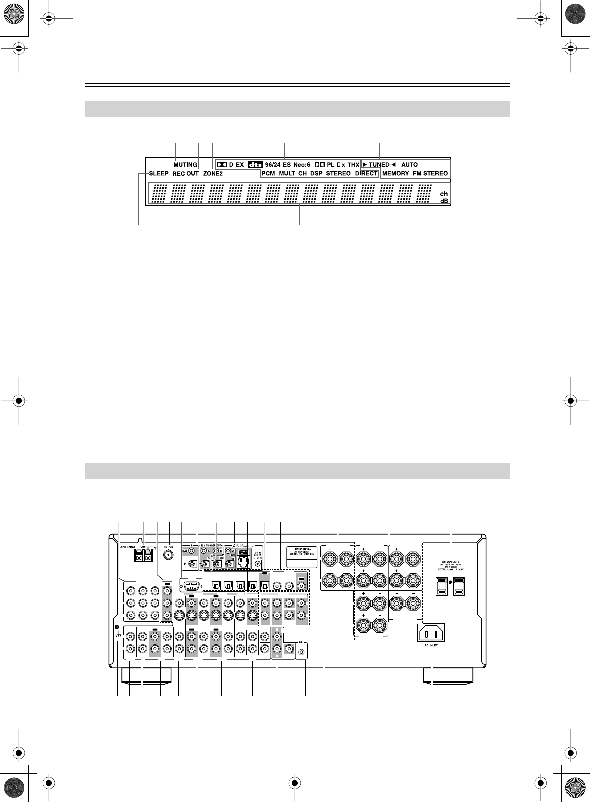
1
MUTING indicator (54)
This indicator flashes while the AV receiver is
muted.
2
REC OUT indicator (64)
This indicator lights up when the REC OUT is
selected.
3
ZONE 2 indicator (77)
This indicator lights up when Zone 2 is selected.
4
Listening mode & format indicators
These indicators show the currently selected listen-
ing mode and the format of digital input signals.
5
Tuning indicators (56)
TUNED:
This indicator lights up when the AV
receiver is tuned into a radio station.
AUTO:
This indicator lights up when the Auto Tun-
ing mode is selected, and disappears when the Man-
ual Tuning mode is selected.
MEMORY:
This indicator lights up when presetting
radio stations.
FM STEREO:
This indicator lights up when the
AV receiver is tuned to a stereo FM station.
6
SLEEP indicator (54)
This indicator lights up when the Sleep function has
been set.
7
Message area
This area of the display shows various information
about the currently selected source.
Display
1 324 5
67
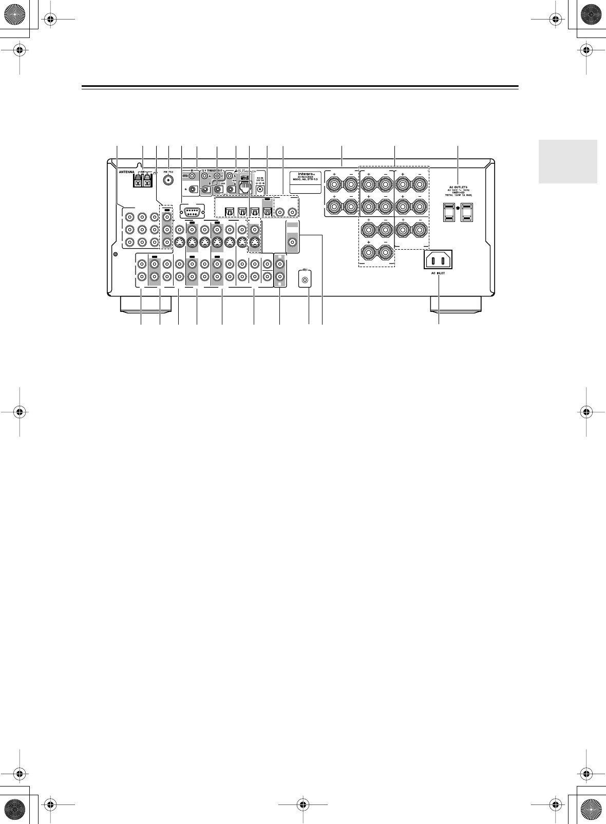
Rear Panel
R
L
R
L
FRONT
SPEAKERS
CENTER
SPEAKER
R
L
R
L
R
L
SURROUND
BACK
SPEAKERS SURROUND
SPEAKERS
IN 1IN 2IN 3
FRONT SURR CENTER
FRONT SURR CENTER
SURR BACK
DVD
CD
VIDEO 3 VIDEO 2 VIDEO 1
VIDEO 3 VIDEO 2 PRE OUT
VIDEO 1
IN IN IN
OUT OUT IN IN
OUT
OUT
TAPE
SUB
WOOFER SUB
WOOFER
SUB
WOOFER
MONITOR
OUT
DVD
COMPONENT VIDEO
P
B
Y
P
R
IN OUT IN IN IN
OUT
R
L
R
L
REMOTE
CONTROL
ZONE 2
OUT
V
S
ZONE 2 SPEAKERS
IN 1IN
2
OUT
OPTICAL
IN1IN2IN3IN
4
OUT
COAXIAL
DIGITAL
RS
232
R
L
PHONO
IN
GND
WVUTSRQPO
GLN
E9JK
1BCD M
XY
6H
Z
DTR-6.5
DTR-6.5,5.5_En.book Page 10 Wednesday, July 28, 2004 9:07 AM
11
Front & Rear Panels
—Continued
For detailed information, see the pages in parentheses.
A
COMPONENT VIDEO IN 1, 2, 3 (28, 30, 32)
These component video inputs can be used to con-
nect AV components with component video outputs,
such as DVD players.
B
AM ANTENNA (24)
These push terminals are for connecting an AM
antenna.
C
COMPONENT VIDEO OUT (27)
This component video output can be used to con-
nect a TV or projector with a component video
input.
D
FM ANTENNA (24)
This jack is for connecting an FM antenna.
E
RS232 (38)
This port is for connecting the AV receiver to home
automation equipment and external controllers.
F
12V TRIGGER OUT A/B/C (73, 78)
These jacks can be connected to the 12-volt trigger
inputs on other components. These trigger outputs
can each be assigned to an input so that when that
input is selected, a 12-volt trigger signal is output.
G
IR IN/OUT (78)
These jacks are for connecting the remote sensors
included with multiroom kits (sold separately).
H
A-BUS
A-BUS is a simple, efficient, elegant audio distribu-
tion system. The wiring installation time is signifi-
cantly reduced as only a single CAT-5 wire is run to
each location. A-BUS is easy to use, reliable,
affordable, and most of all, far better sounding than
conventional auto former based volume controls.
ZONE 2 OUT:
Use CAT-5 (eight conductor
twisted) cable to connect directly from the
receiver’s A-BUS RI45 Hub to an A-BUS keypad.
Warning:
DO NOT connect A-BUS output to any computer or
network connections (i.e. ethernet). it will cause
damage to the computer or network components as
24-volt power runs on this same cable to power the
amplifier stages of the amplifier module.
IR OUT:
Another feature of the A-BUS system is
the ability to control source equipment in another
room where the A-BUS module is installed. If you
wish to control another source from the receiver at
the A-BUS keypad by remote control, connect
A-BUS or another brands’s IR emitter on the
receiver’s 40 K terminal. Then place the emitter on
the remote receiver on the front panel.
Typically, the emitter will work when you connect
with a 40 K connector. If it does not work, try a
56 K connector.
DC IN:
Connect A-Bus power supply. Do not use
any other AC Adapter on this connector as it may
cause severe damage to the receiver.
I
MONITOR OUT (27)
The S-Video or composite video jack should be
connected to a video input on your TV or projector.
R
L
R
L
FRONT
SPEAKERS
CENTER
SPEAKER
R
L
R
L
R
L
SURROUND
BACK
SPEAKERS SURROUND
SPEAKERS
IN 1IN 2IN 3
FRONT SURR CENTER
DVD
CD
VIDEO 3 VIDEO 2 VIDEO 1
VIDEO 3 VIDEO 2 PRE OUT
VIDEO 1
IN IN IN
OUT OUT IN IN
OUT
OUT
TAPE
SUB
WOOFER
SUB
WOOFER
MONITOR
OUT
DVD
COMPONENT VIDEO
P
B
Y
P
R
IN OUT IN IN IN
OUT
REMOTE
CONTROL
ZONE 2
OUT
V
S
ZONE 2 SPEAKERS
IN 1IN
2
OPTICAL
IN1IN2IN3 OUT
COAXIA L
DIGITAL
RS
232
R
L
WVUTSRQ
GLN
E9JK
1BCD M
XY
6H
Z
DTR-5.5
DTR-6.5,5.5_En.book Page 11 Wednesday, July 28, 2004 9:07 AM

12
Front & Rear Panels
—Continued
J
OPTICAL DIGITAL (27, 28, 30, 32, 34, 35)
The DTR-5.5 doesn’t have an IN 4 jack.
The optical digital audio inputs can be used to con-
nect CD and DVD players, and other components
with an optical digital audio output.
The optical output can be used to connect a CD
recorder or other digital recorder with an optical
digital input.
K
COAXIAL DIGITAL (27, 28, 30, 32, 34, 35)
The coaxial digital audio inputs can be used to con-
nect CD and DVD players, and other components
with a coaxial digital audio output.
The coaxial output can be used to connect a CD
recorder or other digital recorder with a coaxial dig-
ital input.
The DTR-5.5 do not have a coaxial output.
L
ZONE 2 SPEAKERS (74)
These terminal posts are for connecting speakers in
Zone 2.
M
FRONT, CENTER, SURROUND &
SURROUND BACK SPEAKERS (23)
These terminal posts are for connecting your front,
center, surround, and surround back speakers.
N
AC OUTLETS (38)
These switched AC outlets can be used to supply
power to other AV components. The type of outlet
depends on the country in which you purchased
your AV receiver. Some models have a single outlet.
O
Grounding screw (DTR-6.5 only) (36)
This screw is for connecting a turntable’s ground
wire.
P
PHONO IN (DTR-6.5 only) (36)
This analog input is for connecting a turntable.
Q
CD IN (34)
This analog audio input is for connecting a CD
player’s analog audio output.
R
TAPE IN/OUT (34)
This analog audio input and output are for connect-
ing a recorder with an analog audio input and output
(cassette, Mini Disc, etc).
S
VIDEO 3 IN (27, 31)
Here you can connect a video source (VCR, set-top
box, etc). Input jacks include S-Video, composite
video, and analog audio.
T
VIDEO 2 IN/OUT (30, 31)
Here you can connect a VCR. Input and output
jacks include S-Video, composite video, and analog
audio.
U
VIDEO 1 IN/OUT (30, 31)
Here you can connect a VCR. Input and output
jacks include S-Video, composite video, and analog
audio.
V
DVD IN (28, 29)
Here you can connect a DVD player. Input jacks
include S-Video, composite video, and analog
audio. You can connect a DVD player’s 2-channel
analog audio output or 5.1-channel analog audio
output.
W
ZONE 2 OUT (74)
This analog audio output can be connected to a line
input on an integrated amplifier in Zone 2.
The DTR-6.5 also has a ZONE 2 OUT SUB-
WOOFER jack that can be used to feed a subwoofer
in Zone 2.
These jacks can can be configured as either line outs
or pre outs on the onscreen setup menus.
X
REMOTE CONTROL (37)
This (Remote Interactive) jack can be con-
nected to an jack on another Integra AV compo-
nent. The AV receiver’s remote controller can then
be used to control that component. To use , you
must make an analog audio connection (RCA)
between the AV receiver and the other AV compo-
nent, even if they are connected digitally.
Y
PRE OUT (37)
These analog audio outputs are for connecting a
separate power amplifier. Useful if you want to con-
nect a more powerful amplifier and use the AV
receiver as a preamp. The SUBWOOFER jack is for
connecting a powered subwoofer.
Z
AC INLET (38)
The supplied power cord should be connected here.
DTR-6.5,5.5_En.book Page 12 Wednesday, July 28, 2004 9:07 AM
13
Remote Controller
Notes:
• The batteries should last for about six months,
although this will vary with usage.
• If the remote controller doesn’t work reliably, try
replacing the batteries.
• Don’t mix new and old batteries or different types of
batteries.
•If you intend not to use the remote controller for a long
time, remove the batteries to prevent damage from
leakage or corrosion.
•Expired batteries should be removed as soon as possi-
ble to prevent damage from leakage or corrosion.
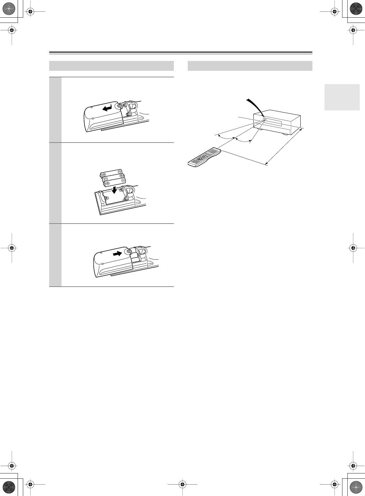
To use the remote controller, point it at the AV receiver’s
remote control sensor, as shown below.
Notes:
•The remote controller may not work reliably if the AV
receiver is subjected to bright light, such as direct sun-
light or inverter-type fluorescent lights. Keep this in
mind when installing.
•If another remote controller of the same type is used in
the same room, or the AV receiver is installed close to
equipment that uses infrared rays, the remote control-
ler may not work reliably.
•Don’t put anything, such as a book, on the remote con-
troller, because the buttons may be pressed inadvert-
ently, thereby draining the batteries.
•The remote controller may not work reliably if the AV
receiver is installed in a rack behind colored glass
doors. Keep this in mind when installing.
•The remote controller will not work if there’s an obsta-
cle between it and the AV receiver’s remote control
sensor.
Installing the Batteries
1
To open the battery compartment, press
the small hollow and slide off the cover.
2
Insert the three supplied batteries (AA/R6)
in accordance with the polarity diagram
inside the battery compartment.
3
Put the cover onto the remote controller
and slide it shut.
Using the Remote Controller
30˚
30˚
AV receiver
Approx. 16 ft.
(5 m)
Remote control sensor
Standby indicator
DTR-6.5,5.5_En.book Page 13 Wednesday, July 28, 2004 9:07 AM
14
Remote Controller
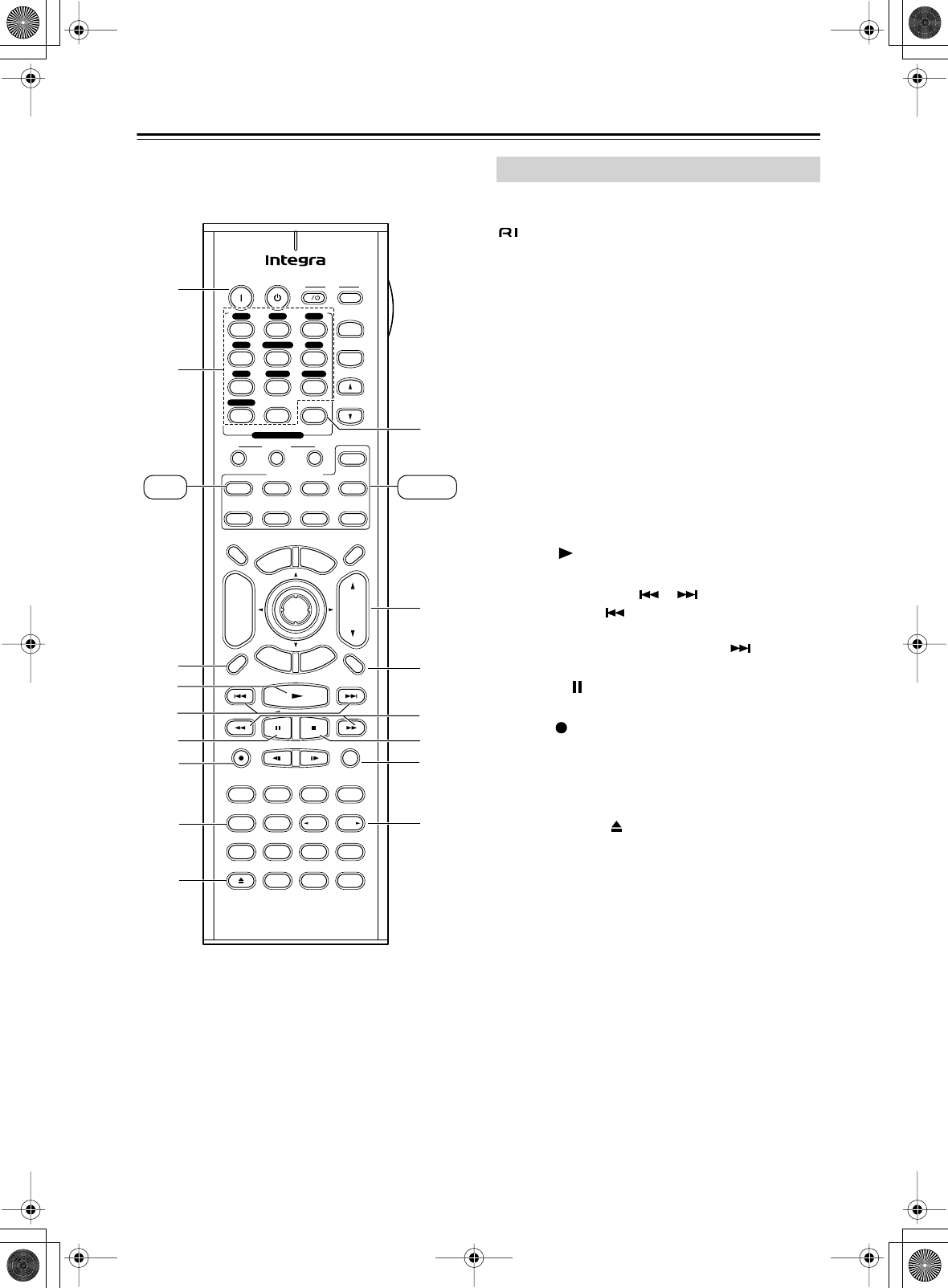
—Continued
In addition to controlling the AV receiver, the remote
controller has several operating modes for controlling
your other AV components, including Integra compo-
nents connected via . Modes are selected by using
the remote controller’s Remote Mode buttons.
For detailed information, see the pages in parentheses.
Some of the functions described in this manual may not
work as expected with other components.
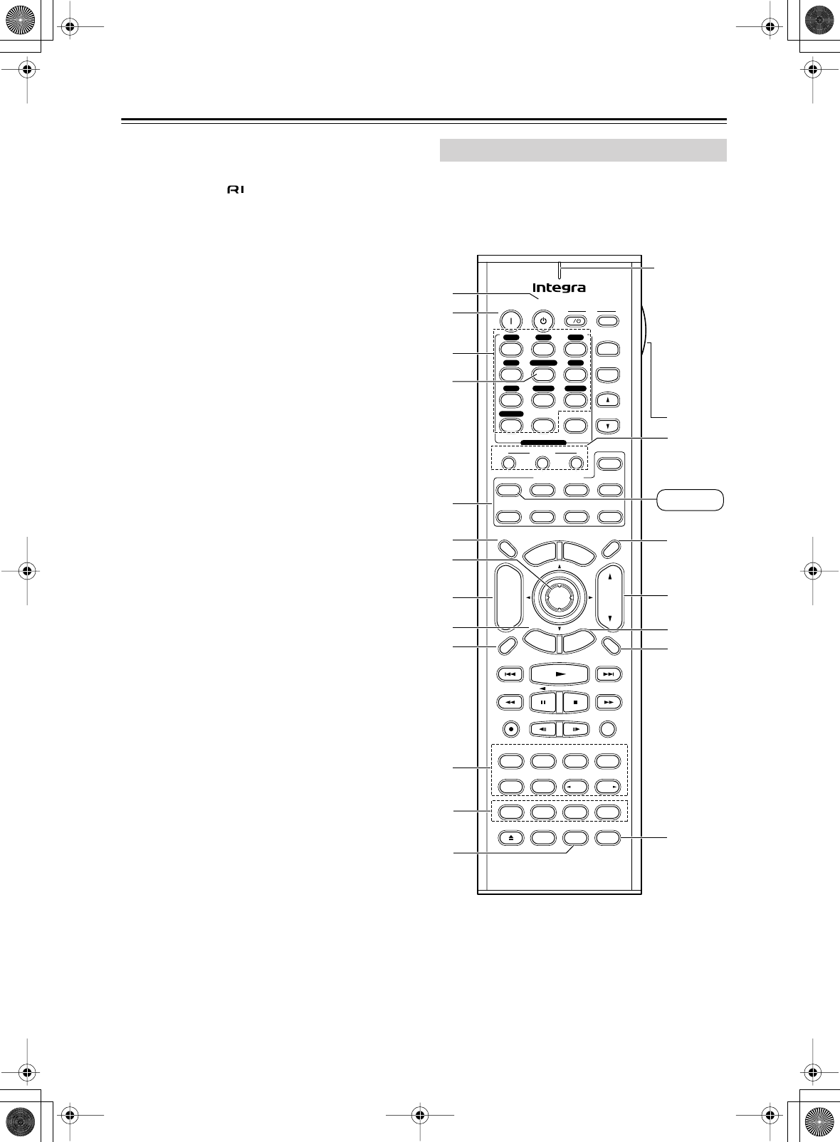
Receiver mode is used to control the AV receiver. To
select Receiver mode, press the [Receiver] Remote
Mode button.
Receiver Mode
Pure A
On Standby TV
Display Muting
RandomRec
Last Memory
AngleSubtitleAudio
MemorySearchA-BRepeat
RC-585M
E
x
i
t
G
u
i
d
e
Prev
CH
TV CH
TV VOL
--
/
---
Dimmer
Tape
TV
Input
Sleep
Input
I
Enter
Test Tone
CH SEL
Surround
THX
Direct
StereoAll ST
Level+
Level-
L Night
DSP DSP
T
o
p
M
e
n
u
M
e
n
u
S
e
t
u
p
R
e
t
u
r
n
VOL
CH
Disc
SATTV VCRCable
DVD
Receiver
CD
+10 0 Clear
123
456
789
+
-
Video OffOpen/Close
Macro
123
MD/CDR
Re-EQ
+
-
Input Selector
V1V2V3
CD
Phono
Tape
V4DVD
Multi CH
Tuner
Remote Mode
Zone 2
8
N
T
Q
M
L
R
P
9
K
B
A
3
5
6
7
4
J
O
S
Receiver
RC-585M
Remote
indicator
This indicator
lights up
when the
remote con-
troller is
transmitting
commands.
DTR-6.5,5.5_En.book Page 14 Wednesday, July 28, 2004 9:07 AM
15
Remote Controller
—Continued
A
Standby button (38)
This button is used to set the AV receiver to
Standby.
B
On button (38)
This button is used to turn on the AV receiver.
C
Input Selector buttons (53)
These buttons are used to select the input source.
Only the RC-588M has a [PHONO] button.
D
Multi CH button (63)
This button is used to select the DVD analog multi-
channel input.
E
Remote Mode buttons
These buttons are used to select the remote control-
ler modes.
F
Dimmer button (54)
This button is used to adjust the display brightness.
G
Arrow [ ]/[ ]/[ ]/[ ] & Enter buttons (42)
These buttons are used to select items on the
onscreen setup menus.
H
CH +/– button (57)
This button is used to select radio presets.
I
Return button
This button is used to return to the previously dis-
played onscreen setup menu.
J
Display button (55, 57)
This button is used to display various information
about the currently selected input source.
K
Listening mode buttons (58)
Surrond button
This button is used to select the Dolby Digital, Pro
Logic IIx, Neo:6, DTS and other listening modes.
All ST button
This button is used to select the All Ch Stereo listen-
ing mode.
THX button (RC-585M only)
This button is used to select the THX listening
modes.
Stereo button
This button is used to select the Stereo listening
mode.
Pure A button
This button is used to select the Pure Audio listen-
ing mode.
Direct button
This button is used to select the Direct listening
mode.
[ DSP] & [DSP ] buttons
These buttons are used to select the Onkyo original
DSP (digital signal processor) listening modes.
L
Test Tone, CH SEL, Level- & Level+ buttons
(50)
These buttons are used to adjust the level of each
speaker individually. The [Level–] & [Level+] but-
tons are also used to adjust the volume in Zone 2.
M
L Night button (62)
This button is used to set the Late Night function.
N
Macro buttons (89)
These buttons are used with the Macro function.
O
Sleep button (54)
This button is used to set the Sleep function.
P
VOL button (53)
This button is used to adjust the volume of the AV
receiver.
Q
Setup button (42)
This button is used to access the onscreen setup
menus that appear on the connected TV.
R
Muting button (54)
This button is used to mute the AV receiver.
S
Re-EQ button (RC-585M only) (62)
This button is used to turn the Re-EQ function on
and off.
T
Light button
This button is used to turn on or off the remote con-
troller’s illuminated buttons.
U
Cine Fltr button (RC-586M only) (62)
This button is used to set the CinemaFILTER func-
tion.
Pure A
RandomRec
Last Memory
AngleSubtitleAudio
MemorySearchA-BRepeat
RC-586M
Test Tone
CH SEL
Surround
Direct
StereoAll ST
Level+
Level-
L Night
DSP DSP
Video OffOpen/Close
Cine Fltr
U
RC-586M
DTR-6.5,5.5_En.book Page 15 Wednesday, July 28, 2004 9:07 AM
16
Remote Controller
—Continued
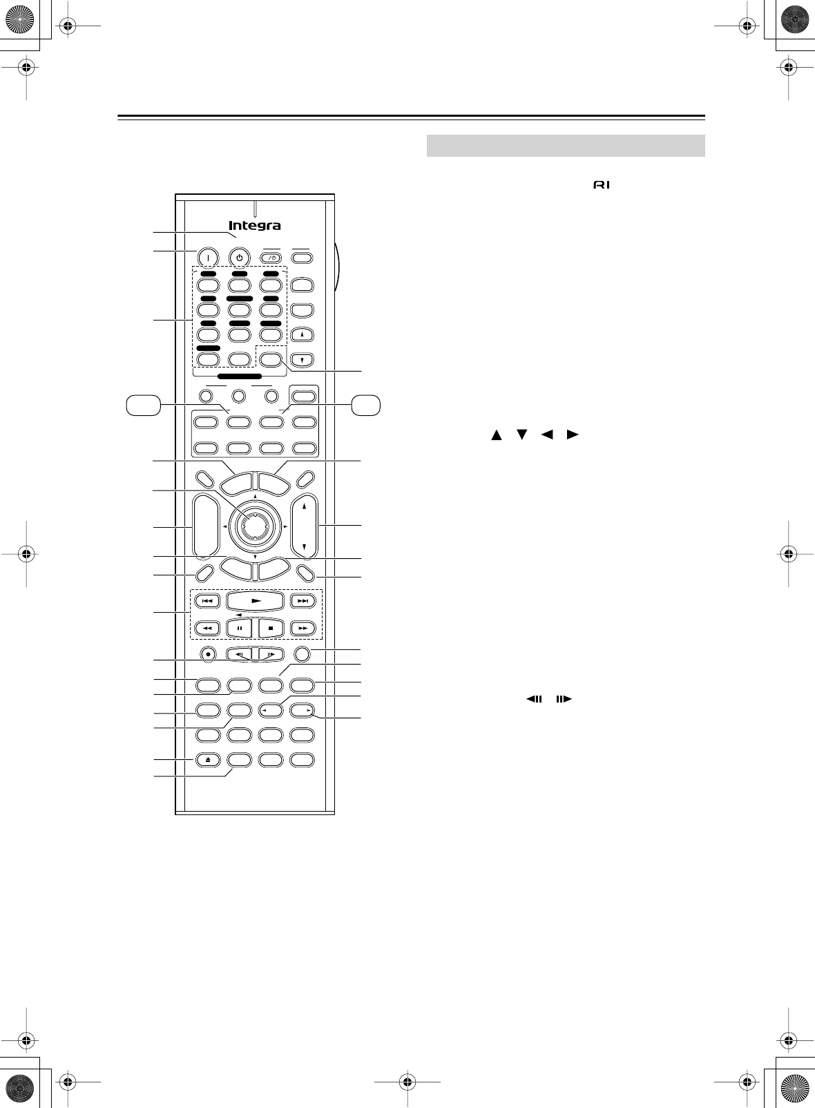
DVD mode is used to control an Integra DVD player
connected to the AV receiver via .
To set the remote controller to DVD mode, press the
[DVD] Remote Mode button.
A
Standby button
This button is used to set the DVD player to
Standby.
B
On button
This button is used to turn on the DVD player and to
set it to Standby.
C
Number buttons
These buttons are used to enter title, chapter, and
track numbers, and to enter times for locating spe-
cific points in time.
D
Top Menu button
This button is used to select a DVD’s top menu.
E
Arrow [ ]/[ ]/[ ]/[ ] & Enter buttons
These buttons are used to navigate DVD menus and
the DVD player’s onscreen setup menus.
F
Disc +/– button
This button selects discs on a DVD changer.
G
Return/Exit button
This button is used to exit the DVD player’s
onscreen setup menu.
H
Display button
This button is used to display information about the
current disc, title, chapter, or track on the DVD
player’s display, including the elapsed time, remain-
ing time, total time, and so on.
I
Playback buttons
From left to right: Previous, Play, Next, Fast
Reverse, Pause, Stop, and Fast Forward.
J
Step & Slow [ ]/[ ] buttons
These buttons are used for frame-by-frame playback
and slow-motion playback.
K
Audio button
This button is used to select foreign language
soundtracks and audio formats (e.g., Dolby Digital
or DTS).
L
Subtitle button
This button is used to select subtitles.
M
Repeat button
This button is used to set the repeat playback func-
tions.
Pure A
On Standby TV
Display Muting
RandomRec
Last Memory
AngleSubtitleAudio
MemorySearchA-BRepeat
RC-585M
E
x
i
t
G
u
i
d
e
Prev
CH
TV CH
TV VOL
--
/
---
Dimmer
Tape
TV
Input
Sleep
Input
I
Enter
Test Tone
CH SEL
Surround
THX
Direct
StereoAll ST
Level+
Level-
L Night
DSP DSP
T
o
p
M
e
n
u
M
e
n
u
S
e
t
u
p
R
e
t
u
r
n
VOL
CH
Disc
SATTV VCR Cable
DVD
Receiver
CD
+10 0 Clear
123
456
789
+
-
Video OffOpen/Close
Macro
123
MD/CDR
Re-EQ
+
-
Input Selector
V1V2V3
CD
Phono
Tape
V4DVD
Multi CH
Tuner
Remote Mode
Zone 2
6
Q8
9
0
A
B
1
2
3
4
5
6
7
T
O
P
M
N
K
L
U
S
7
9
J
B
A
3
5
4
8
R
V
W
Y
X
Z
DVD CD
Round numbers are for DVD mode.
Square numbers are for CD mode.
DVD Mode
DTR-6.5,5.5_En.book Page 16 Wednesday, July 28, 2004 9:07 AM

17
Remote Controller
—Continued
N
A-B button
This button is used to set the A–B repeat playback
function.
O
Open/Close [ ] button
This button is used to open and close the disc tray.
P
Video Off button
This button is used to turn off the internal video cir-
cuitry, eliminating any possibility of interference.
Q
Clear button
This button is used to cancel functions and to clear
entered numbers.
R
Menu button
This button is used to display a DVD’s menu.
S
VOL button
This button is used to adjust the volume of the AV
receiver.
T
Setup/Guide button
This button is used to access the DVD player’s
onscreen setup menus.
U
Muting button
This button is used to mute the AV receiver.
V
Random button
This button is used with the random playback func-
tion.
W
Angle button
This button is used to select camera angles.
X
Last M button
This button is used with the last memory function,
which allows you to resume DVD playback from
where you left off.
Y
Search button
This button is used to search for titles, chapters,
tracks, and specific points in time.
Z
Memory button
This button is used with the memory playback func-
tion, which allows you to create a custom playlist of
titles, chapters, or tracks.
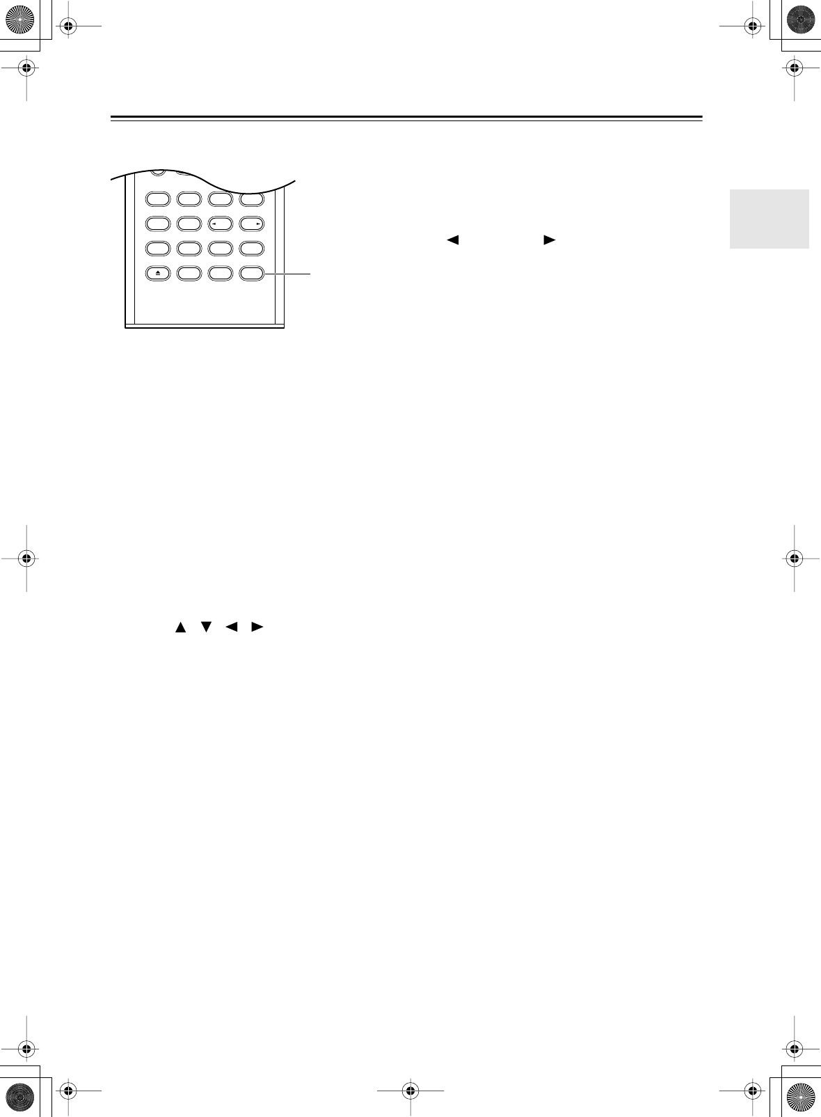
CD mode is used to control an Integra CD player con-
nected to the AV receiver via .
To set the remote controller to CD mode, press the
[CD] Remote Mode button.
1
On button
This button is used to set the CD player to On or
Standby.
2
Number buttons
These buttons are used to enter track numbers and
to enter times for locating specific points in time.
3
Disc button
This button is used to select discs on a CD changer.
4
Display button
This button is used to display information about the
current disc or track on the CD player’s display,
including the elapsed time, remaining time, total
time, and so on.
5
Playback buttons
From left to right: Previous, Play, Next, Fast
Reverse, Pause, Stop, and Fast Forward.
6
Repeat button
This button is used to set the repeat playback func-
tions.
7
Open/Close [ ] button
This button is used to open and close the disc tray.
8
Clear button
This button is used to cancel functions and to clear
entered numbers.
9
VOL button
This button is used to adjust the volume of the AV
receiver.
0
Muting button
This button is used to mute the AV receiver.
A
Random button
This button is used with the random playback func-
tion.
B
Memory button
This button is used with the memory playback func-
tion, which allows you to create a custom playlist of
tracks.
CD Mode
DTR-6.5,5.5_En.book Page 17 Wednesday, July 28, 2004 9:07 AM
18
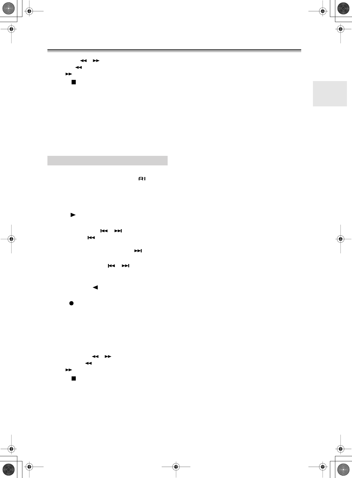
Remote Controller
—Continued
MD/CDR mode is used to control an Integra MiniDisc
recorder or CD recorder connected to the AV receiver via
.
To select MD/CDR mode, press the [MD/CDR]
Remote Mode button.
By default, this button is set to control a MiniDisc
recorder. To control a CD recorder, it must be set to CDR
(see page 80).
A
On button
This button is used to set the MD recorder or CD
recorder to On or Standby.
B
Number buttons
These buttons are used to enter track numbers and
to enter times for locating specific points in time.
C
Display button
This button is used to display information about the
current disc or track on the MD recorder or CDR
recorder’s display, including the elapsed time,
remaining time, total time, and so on.
D
Play [ ] button
This button is used to start playback.
E
Previous & Next [ ]/[ ] buttons
The Previous [ ] button is used to select the pre-
vious track. During playback it selects the begin-
ning of the current track. The Next [ ] button is
used to select the next track.
F
Pause [ ] button
This button is used to pause playback.
G
Rec [ ] button
This button is used to start recording.
H
Repeat button
This button is used to set the repeat playback func-
tions.
I
Open/Close [ ] button
This button is used to eject a MiniDisc or to open
and close the CD recorder’s disc tray.
J
Clear button
This button is used to cancel functions and to clear
entered numbers.
K
VOL button
This button is used to adjust the volume of the AV
receiver.
L
Muting button
This button is used to mute the AV receiver.
Pure A
On Standby TV
Display Muting
RandomRec
Last Memory
AngleSubtitleAudio
MemorySearchA-BRepeat
RC-585M
E
x
i
t
G
u
i
d
e
Prev
CH
TV CH
TV VOL
--
/
---
Dimmer
Tape
TV
Input
Sleep
Input
I
Enter
Test Tone
CH SEL
Surround
THX
Direct
StereoAll ST
Level+
Level-
L Night
DSP DSP
T
o
p
M
e
n
u
M
e
n
u
S
e
t
u
p
R
e
t
u
r
n
VOL
CH
Disc
SATTV VCRCable
DVD
Receiver
CD
+10 0 Clear
123
456
789
+
-
Video OffOpen/Close
Macro
123
MD/CDR
Re-EQ
+
-
Input Selector
V1V2V3
CD
Phono
Tape
V4DVD
Multi CH
Tuner
Remote Mode
Zone 2
J
5
6
7
8
1
2
3
4
9
8
7
L
K
1
2
3
O
P
Tape MD/CDR
6
M
4
5
N
Round numbers are for MD/CDR mode.
Square numbers are for TAPE mode.
MD/CDR Mode
DTR-6.5,5.5_En.book Page 18 Wednesday, July 28, 2004 9:07 AM
19
Remote Controller
—Continued
M
FR & FF [ ]/[ ] buttons
The FR [ ] button is used to start fast reverse. The
FF [ ] button is used to start fast forward.
N
Stop [ ] button
This button is used to stop playback.
O
Random button
This button is used with the random playback func-
tion.
P
Memory button
This button is used with the memory playback func-
tion, which allows you to create a custom playlist of
tracks.
TAPE mode is used to control an Integra cassette
recorder connected to the AV receiver via .
To set the remote controller to TAPE mode, press the
[Tape] Remote Mode button.
For double cassette decks, only Deck B can be con-
trolled.
1
Play [ ] button
This button is used to start playback.
2
Previous & Next [ ]/[ ] buttons
The Previous [ ] button is used to select the pre-
vious track. During playback it selects the begin-
ning of the current track. The Next [ ] button is
used to select the next track.
The Previous and Next [ ]/[ ] buttons may not
work properly with some cassette tapes depending
on how they were recorded.
3
Reverse Play [ ] button
This button is used to start reverse playback.
4
Rec [ ] button
This button is used to start recording.
5
VOL button
This button is used to adjust the volume of the AV
receiver.
6
Muting button
This button is used to mute the AV receiver.
7
Rewind & FF [ ]/[ ] buttons
The Rewind [ ] button is used to start rewind. The
FF [ ] button is used to start fast forward.
8
Stop [ ] button
This button is used to stop playback.
TAPE Mode
DTR-6.5,5.5_En.book Page 19 Wednesday, July 28, 2004 9:07 AM
20
About Home Theater
Thanks to the AV receiver’s superb capabilities, you can enjoy surround sound with a real sense of movement in your
own home—just like being in a movie theater or concert hall. With DVDs you can enjoy DTS and Dolby Digital. With
analog and digital TV you can enjoy Dolby Pro Logic IIx or Onkyo’s own DSP surround listening modes.
With the DTR-6.5 you can enjoy DVDs that feature THX Surround EX (THX-certified THX speaker system recom-
mended).
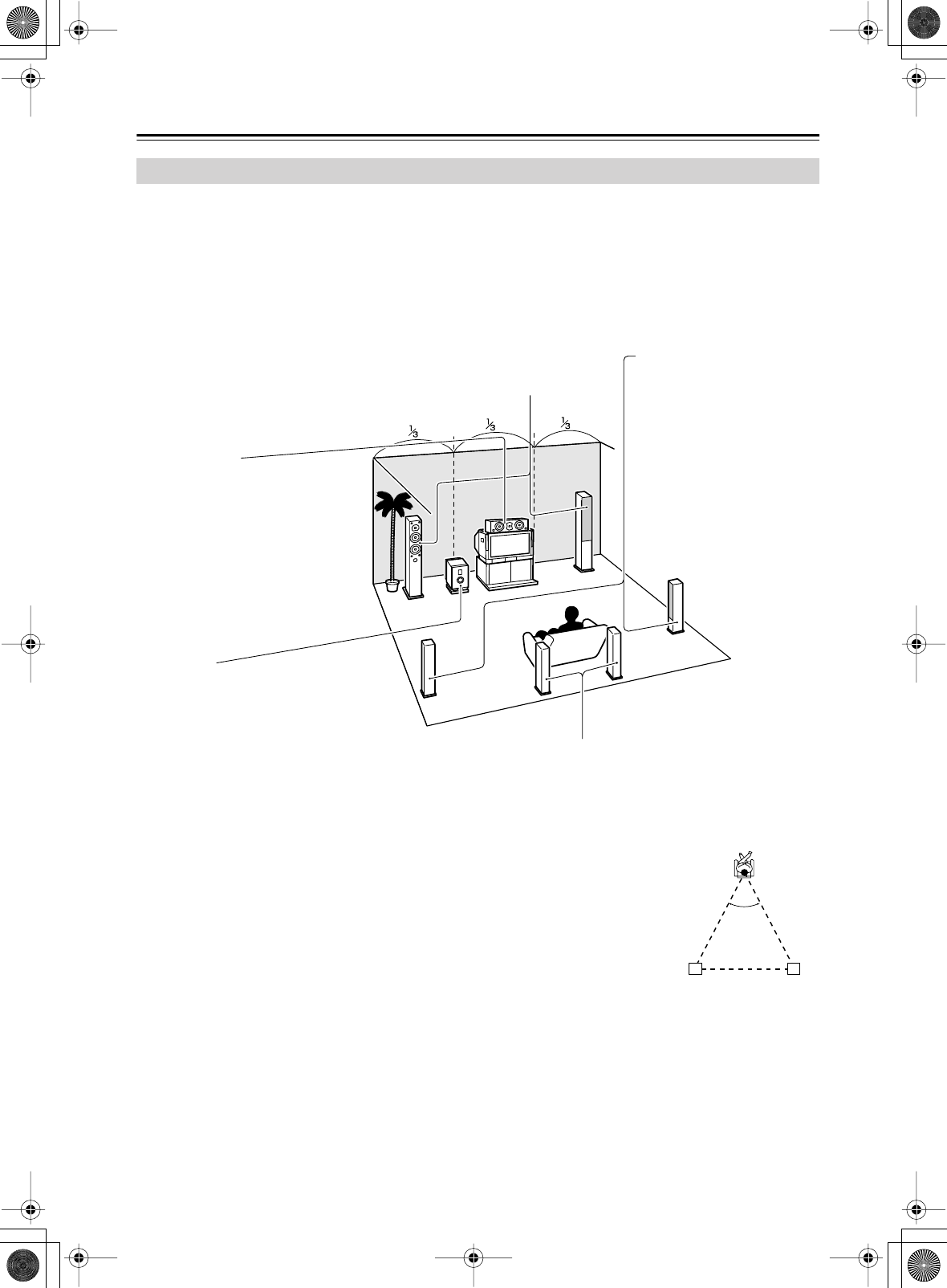
Enjoying Home Theater
Front left and right speakers
These output the overall sound. Their role in a home theater is to provide a solid
anchor for the sound image. They should be positioned facing the listener at about
ear level, and equidistant from the TV. Angle them inward so as to create a triangle,
with the listener at the apex.
Center speaker
This speaker enhances the front left
and right speakers, making sound
movements distinct and providing a
full sound image. In movies it’s used
mainly for dialog.
Position it close to your TV (preferably
on top) facing forward at about ear
level, or at the same height as the
front left and right speakers.
Subwoofer
The subwoofer handles the bass sounds of
the LFE (Low-Frequency Effects) channel.
The volume and quality of the bass output
from your subwoofer will depend on its posi-
tion, the shape of your listening room, and
your listening position. In general, a good
bass sound can be obtained by installing the
subwoofer in a front corner, or at one-third
the width of the wall, as shown.
Tip: To find the best position for your sub-
woofer, while playing a movie or some
music with good bass, experiment by plac-
ing your subwoofer at various positions
within the room, and choose the one that
provides the most satisfying results.
Surround back left and right speakers
These speakers are necessary to enjoy Dolby Digital EX, DTS-ES
Matrix, DTS-ES Discrete, and THX Surround EX (DTR-6.5 only). They
enhance the realism of surround sound and improve sound localization
behind the listener. Position them behind the listener about 2–3 feet (60–
100 cm) above ear level.
For the DTR-6.5, THX recommends that
they be placed equidistant from the listener,
creating a triangle, and that the angle at the
apex of the triangle is about 60 degrees.
Make sure that the listening position is within
the range of the speakers.
60˚
Surround
back left
speaker
Surround
back right
speaker
Surround left and right
speakers
These speakers are used for
precise sound positioning and
to add realistic ambience.
Position them at the sides of
the listener, or slightly behind,
about 2–3 feet (60–100 cm)
above ear level. Ideally they
should be equidistant from the
listener.
DTR-6.5,5.5_En.book Page 20 Wednesday, July 28, 2004 9:07 AM
21
Connecting the AV receiver
•Before making any AV connections, read the manuals
supplied with your other AV components.
•Don’t connect the power cord until you’ve completed
and double-checked all AV connections.
Optical Digital Jacks
The AV receiver’s optical digital jacks have shutter-type
covers that open when an optical plug is inserted and
close when it’s removed. Push plugs in all the way.
Caution:
To prevent shutter damage, hold the optical
plug straight when inserting and removing.
AV Connection Color Coding
RCA-type AV connections are usually color coded: red,
white, and yellow. Use red plugs to connect right-
channel audio inputs and outputs (typically labeled “R”).
Use white plugs to connect left-channel audio inputs and
outputs (typically labeled “L”). And use yellow plugs to
connect composite video inputs and outputs.
•Push plugs in all the way to make
good connections (loose connec-
tions can cause noise or malfunc-
tions).
•To prevent interference, keep
audio and video cables away from
power cords and speaker cables.
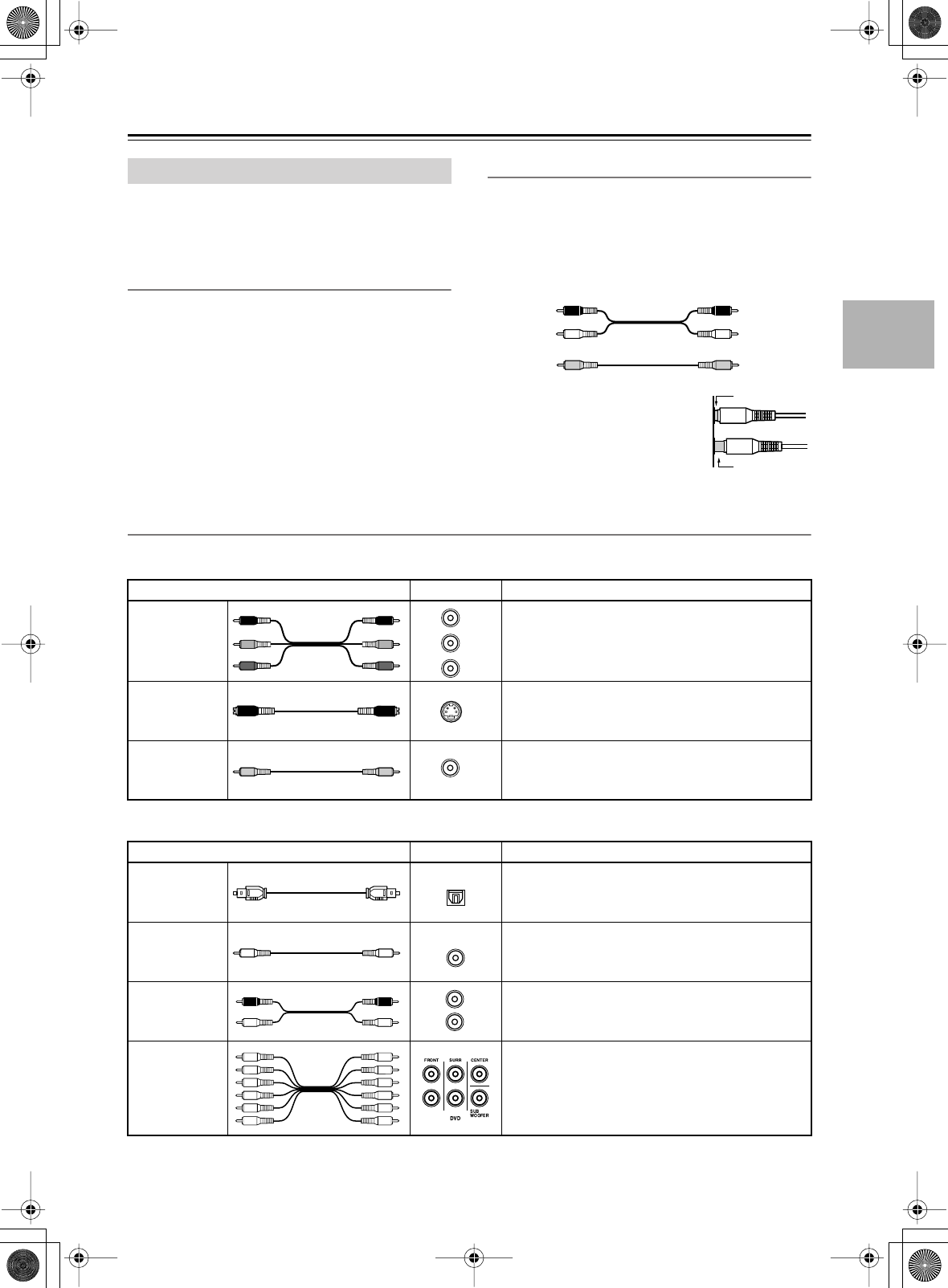
AV Cables & Jacks
About AV Connections
Right (red)
Left (white)
(Yellow)
Analog audio
Composite video
Right (red)
Left (white)
(Yellow)
Right!
Wrong!
Video
Cable Jack Description
Component
video cable
Component video separates the luminance (Y) and
color difference signals (P
R
, P
B
), providing the best
picture quality. (Some TV manufacturers label their
component video sockets slightly differently.)
S-Video cable
S-Video separates the luminance and color signals
and provides better picture quality than composite
video.
Composite
video cable
Composite video is commonly used on TVs, VCRs,
and other video equipment. Use only dedicated
composite video cables.
Audio
Cable Jack Description
Optical digital
audio cable
Offers the best sound quality and allows you to
enjoy surround sound (e.g., Dolby Digital, DTS).
The audio quality is the same as for coaxial.
Coaxial digital
audio cable
Offers the best sound quality and allows you to
enjoy surround sound (e.g., Dolby Digital, DTS).
The audio quality is the same as for optical.
Analog audio
cable (RCA)
This cable carries analog audio. It’s the most
common connection format for analog audio, and
can be found on virtually all AV components.
Multichannel
analog audio
cable (RCA)
This cable carries multichannel analog audio and
it’s typically used to connect DVD players with a
5.1-channel analog audio output. Several standard
analog audio cables can be used instead of a multi-
channel cable.
Y
P
R
P
B
P
R
P
B
Y
Y
PB
PR
S
V
OPTICAL
COAXIAL
L
R
DTR-6.5,5.5_En.book Page 21 Wednesday, July 28, 2004 9:07 AM
22
Connecting the AV receiver
—Continued
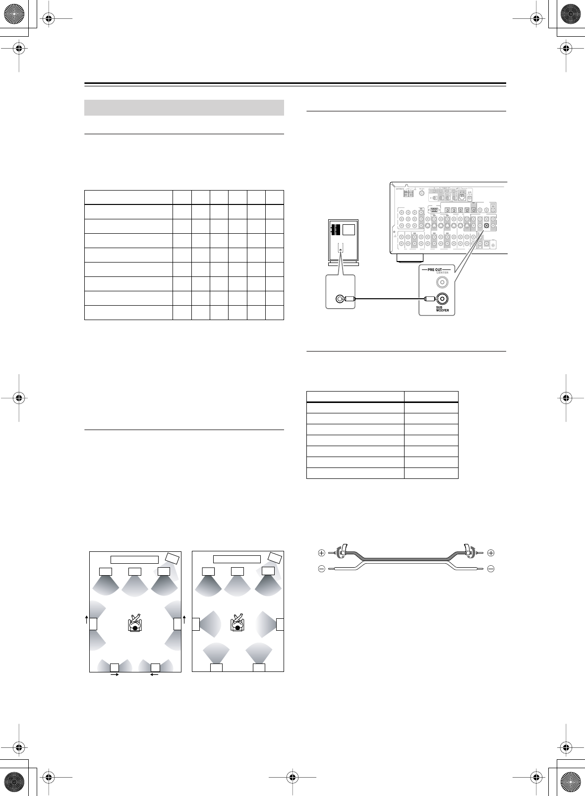
Speaker Configuration
For the best surround-sound experience, you should con-
nect seven speakers and a powered subwoofer.
The following table indicates the channels you should
use depending on the number of speakers that you have.
*If you’re using only one surround back speaker, connect it to
the left (L) SURROUND BACK SPEAKERS terminals.
No matter how many speakers you use, a powered sub-
woofer is recommended for a really powerful and solid
bass.
To get the best from your surround-sound system, you
need to set the speaker settings by using the supplied
setup microphone (see page 39).
Using Dipole Speakers
You can use dipole speakers for the surround left and
right and surround back left and right speakers. Dipole
speakers output the same sound in two directions.
Dipole speakers typically have an arrow printed on them
to indicate how they should be positioned. The surround
left and right
dipole
speakers should be positioned so that
their arrows point toward the TV/screen, while the sur-
round left and right dipolar speakers should be positioned
so that their arrows point toward each other, as shown.
Connecting a Powered Subwoofer
Using a suitable cable, connect the AV receiver’s SUB-
WOOFER PRE OUT to an input on your powered sub-
woofer, as shown. If your subwoofer is unpowered and
you’re using an external amplifier, connect the SUB-
WOOFER PRE OUT to an input on the amp.
Attaching the Speaker Labels
The AV receiver’s positive (+) speaker terminals are
color-coded for ease of identification. (The negative (–)
speaker terminals are all black.)
The supplied speaker labels are also color-coded and you
should attach them to the positive (+) side of each
speaker cable in accordance with the above table. All you
need to do then is to match the color of each label to the
corresponding speaker terminal.
Connecting Your Speakers
Number of speakers: 234567
Front left
✓✓✓✓✓✓
Front right
✓✓✓✓✓✓
Center
✓✓✓✓
Surround left
✓✓✓✓
Surround right
✓✓✓✓
Surround back*
✓
Surround back left
✓
Surround back right
✓
2
1
34
2
1
34
5
7 8
656
78
TV/screen TV/screen
1. Subwoofer
2. Front left speaker
3. Center speaker
4. Front right speaker
5. Surround left speaker
6. Surround right speaker
7. Surround back left
speaker
8. Surround back right
speaker
Dipole speakers Normal speakers
Speaker terminal Color
Front left, Zone 2 left White
Front right, Zone 2 right Red
Center Green
Surround left Blue
Surround right Gray
Surround back left Brown
Surround back right Tan
R
L
IN 1IN 2IN 3
FRONT SURR CENTER
FRONT SURR CENTER
SURR BACK
DVD
CD
VIDEO 3 VIDEO 2 VIDEO 1
VIDEO 3 VIDEO 2 PRE OUT
VIDEO 1
IN IN IN
OUT OUT IN IN
OUT
OUT
TAPE
SUB
WOOFER SUB
WOOFER
SUB
WOOFER
MONITOR
OUT
DVD
COMPONENT VIDEO
P
B
Y
P
R
IN OUT IN IN IN
OUT
R
L
R
L
REMOTE
CONTROL
ZONE 2
OUT
V
S
IN 1IN
2
OUT
OPTICAL
IN1IN2IN3IN
4
OUT
COAXIAL
DIGITAL
RS
232
R
L
PHONO
IN
GND
LINE INPUT
LINE INPUT
Powered
subwoofer
DTR-6.5,5.5_En.book Page 22 Wednesday, July 28, 2004 9:07 AM
23
Connecting the AV receiver
—Continued
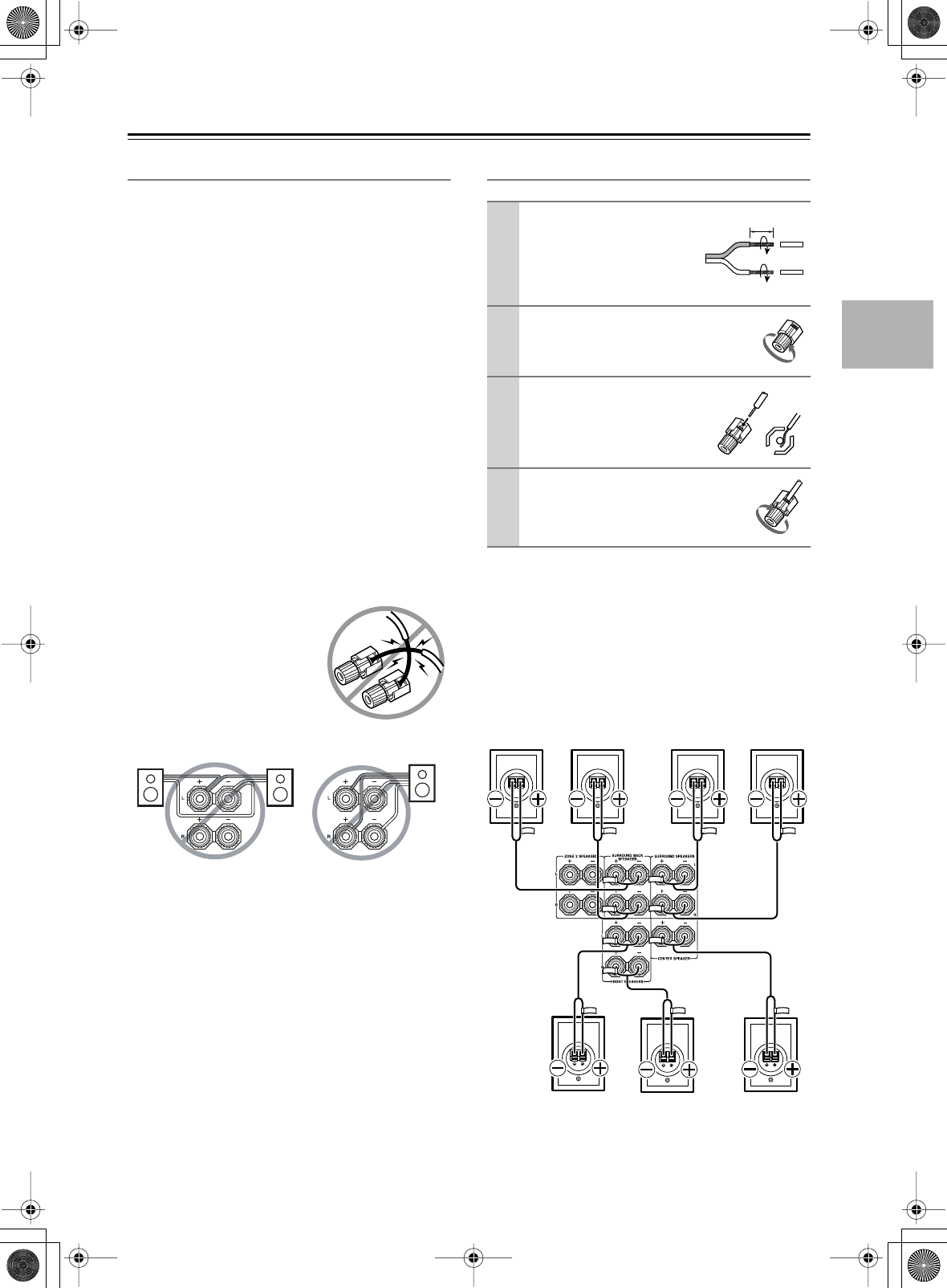
Speaker Connection Precautions
Read the following before connecting your speakers:
•
American model only:
Only connect speakers with
an impedance of 6 ohms or higher. If you use speakers
with a lower impedance, and use the amplifier at high
volume levels for a long period of time, the built-in
protection circuit may be activated.
•
Other models:
You can connect speakers with an
impedance of between 4 and 16 ohms. If the imped-
ance of any of the connected speakers is 4 ohms or
more, but less than 6 ohms, be sure to set the Mini-
mum Speaker Impedance to “4 ohms” (see page 44).
If you use speakers with a lower impedance, and use
the amplifier at high volume levels for a long period of
time, the built-in protection circuit may be activated.
•Disconnect the power cord from the wall outlet before
making any connections.
• Read the instructions supplied with your speakers.
•Pay close attention to speaker wiring polarity. In other
words, connect positive (+) terminals to only positive
(+) terminals, and negative (–) terminals to only nega-
tive (–) terminals. If you get them the wrong way
around, the sound will be out of phase and will sound
unnatural.
• Unnecessarily long, or very thin speaker cables may
affect the sound quality and should be avoided.
• Be careful not to short the
positive and negative wires.
Doing so may damage the AV
receiver.
• Don’t connect more than one
cable to each speaker termi-
nal. Doing so may damage the
AV receiver.
• Don’t connect one speaker to several terminals.
Connecting the Speaker Cables
The following illustration shows which speaker should
be connected to each pair of terminals.
If you’re using only one surround back speaker, connect
it to the left (L) SURROUND BACK SPEAKERS termi-
nals.
1
Strip about 5/8" (15 mm)
of insulation from the
ends of the speaker
cables, and twist the bare
wires tightly, as shown.
2
Unscrew the terminal.
3
Fully insert the bare
wires.
4
Screw the terminal tight.
5/8" (15 mm)
Surround
back left
speaker
Surround
back right
speaker
Front left
speaker
Front right
speaker
Center
speaker
Surround
right
speaker
Surround
left
speaker
DTR-6.5,5.5_En.book Page 23 Wednesday, July 28, 2004 9:07 AM
24
Connecting the AV receiver
—Continued
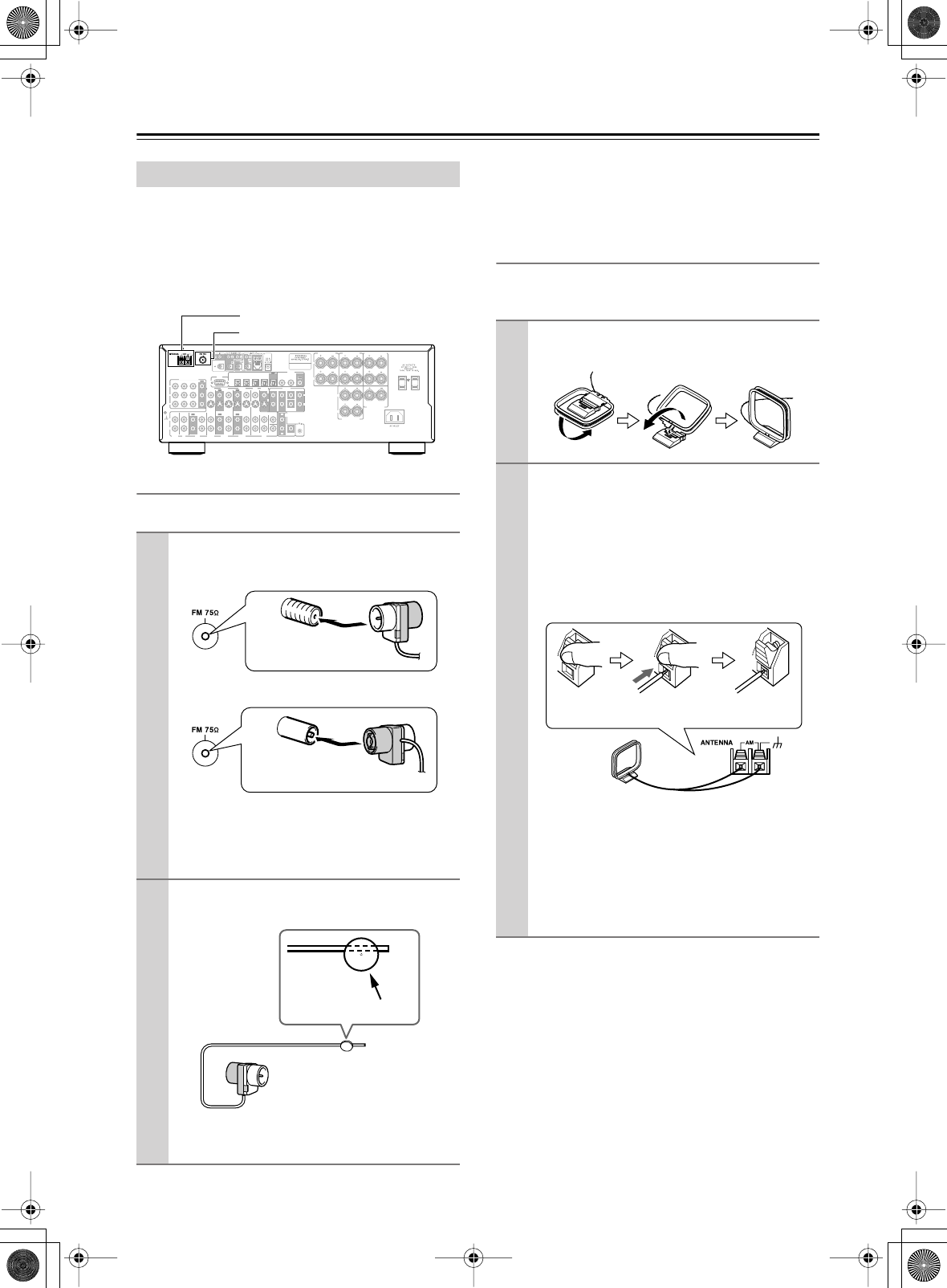
This section explains how to connect the supplied indoor
FM antenna and AM loop antenna, and how to connect
commercially available outdoor FM and AM antennas.
The AV receiver won’t pick up any radio signals without
any antenna connected, so you must connect the antenna
to use the tuner.
Connecting the Indoor FM Antenna
The supplied indoor FM antenna is for indoor use only.
If you cannot achieve good reception with the supplied
indoor FM antenna, try a commercially available out-
door FM antenna instead (see page 25).
Connecting the AM Loop Antenna
The supplied indoor AM loop antenna is for indoor use
only.
If you cannot achieve good reception with the supplied
indoor AM loop antenna, try using it with a commer-
cially available outdoor AM antenna (see page 25).
Connecting Antenna
1
Attach the FM antenna, as shown.
■
American Model
■
Other Models
Once your AV receiver is ready for use, you’ll
need to tune into an FM radio station and adjust
the position of the FM antenna to achieve the best
possible reception.
2
Use thumbtacks or something similar to
fix the FM antenna into position.
Caution:
Be careful that you don’t injure yourself
when using thumbtacks.
R
L
R
L
FRONT
SPEAKERS
CENTER
SPEAKER
R
L
R
L
R
L
SURROUND
BACK
SPEAKERS SURROUND
SPEAKERS
IN 1IN 2IN 3
FRONT SURR CENTER
FRONT SURR CENTER
SURR BACK
DVD
CD
VIDEO 3 VIDEO 2 VIDEO 1
VIDEO 3 VIDEO 2 PRE OUT
VIDEO 1
IN IN IN
OUT OUT IN IN
OUT
OUT
TAPE
SUB
WOOFER SUB
WOOFER
SUB
WOOFER
MONITOR
OUT
DVD
COMPONENT VIDEO
P
B
Y
P
R
IN OUT IN IN IN
OUT
R
L
R
L
REMOTE
CONTROL
ZONE 2
OUT
V
S
ZONE 2 SPEAKERS
IN 1IN
2
OUT
OPTICAL
IN1IN2IN3IN
4
OUT
COAXIAL
DIGITAL
RS
232
R
L
PHONO
IN
GND
AM antenna push terminals
FM antenna connector
Insert the plug fully
into the jack.
Insert the plug fully
into the jack.
Thumbtacks, etc.
1
Assemble the AM loop antenna, inserting
the tabs into the base, as shown.
2
Connect both wires of the AM loop
antenna to the AM push terminals, as
shown.
(The antenna’s wires are not polarity sensitive, so
they can be connected either way around).
Make sure that the wires are attached securely and
that the push terminals are gripping the bare
wires, not the insulation.
Once your AV receiver is ready for use, you’ll
need to tune into an AM radio station and adjust
the position of the AM antenna to achieve the best
possible reception.
Keep the antenna as far away as possible from
your AV receiver, TV, speaker cables, and power
cords.
Push Insert wire Release
DTR-6.5,5.5_En.book Page 24 Wednesday, July 28, 2004 9:07 AM
25
Connecting the AV receiver
—Continued
Connecting an Outdoor FM Antenna
If you cannot achieve good reception with the supplied
indoor FM antenna, try a commercially available out-
door FM antenna instead.
Notes:
• Outdoor FM antennas work best outside, but usable
results can sometimes be obtained when installed in an
attic or loft.
•For best results, install the outdoor FM antenna well
away from tall buildings, preferably with a clear line
of sight to your local FM transmitter.
• Outdoor antenna should be located away from possi-
ble noise sources, such as neon signs, busy roads, etc.
•For safety reasons, outdoor antenna should be situated
well away from power lines and other high-voltage
equipment.
• Outdoor antenna must be grounded in accordance
with local regulations to prevent electrical shock haz-
ards.
■
Using a TV/FM Antenna Splitter
It’s best not to use the same antenna for both FM and TV
reception, as this can cause interference problems. If cir-
cumstances demand it, use a TV/FM antenna splitter, as
shown.
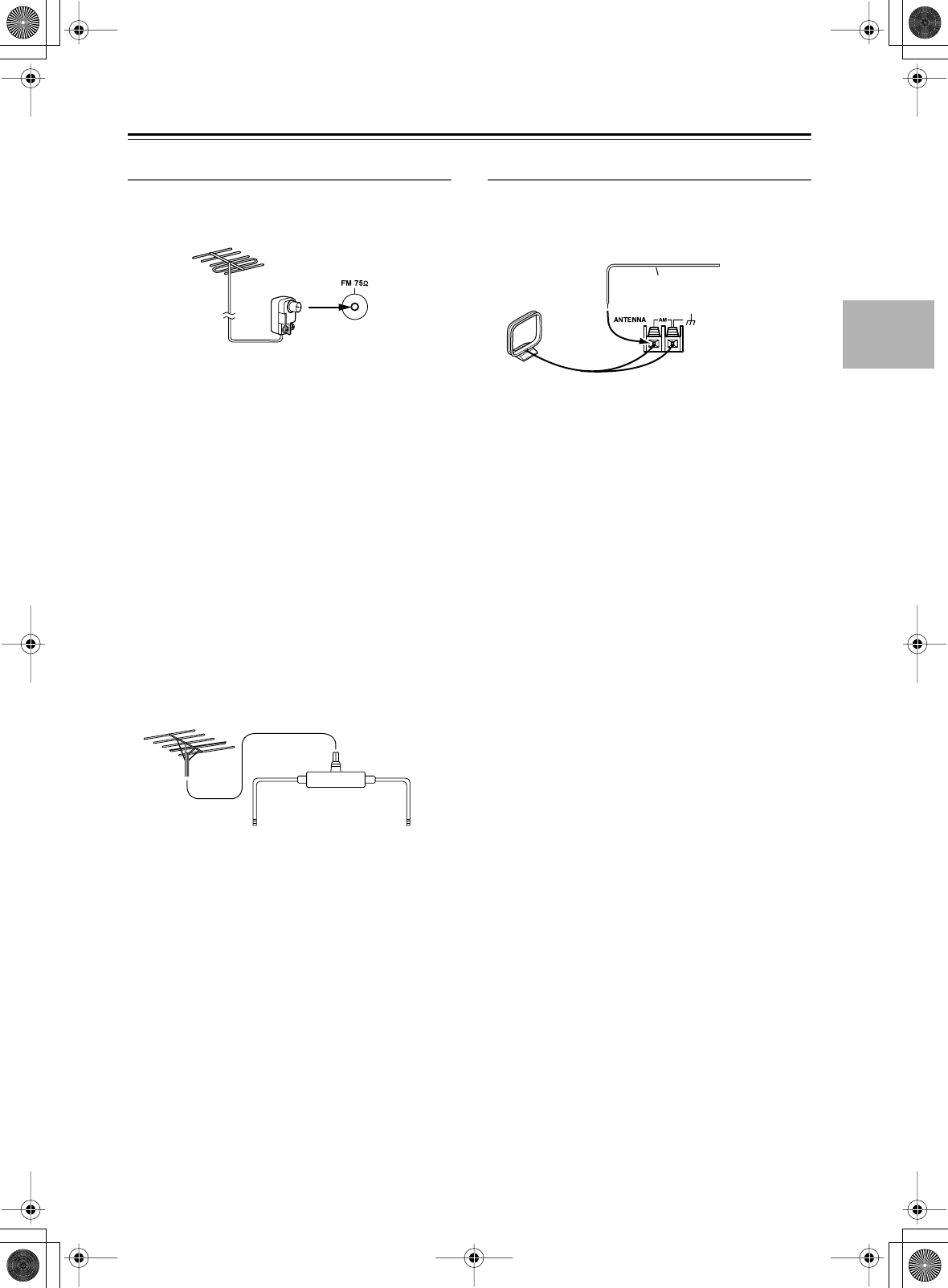
Connecting an Outdoor AM Antenna
If good reception cannot be achieved using the supplied
AM loop antenna, an outdoor AM antenna can be used in
addition to the loop antenna, as shown.
Outdoor AM antennas work best when installed outside
horizontally, but good results can sometimes be obtained
indoors by mounting horizontally above a window. Note
that the AM loop antenna should be left connected.
Outdoor antenna must be grounded in accordance with
local regulations to prevent electrical shock hazards.
To AV receiver To TV (or VCR)
TV/FM antenna splitter
Outdoor antenna
AM loop antenna
Insulated antenna cable
DTR-6.5,5.5_En.book Page 25 Wednesday, July 28, 2004 9:07 AM
26
Connecting the AV receiver
—Continued
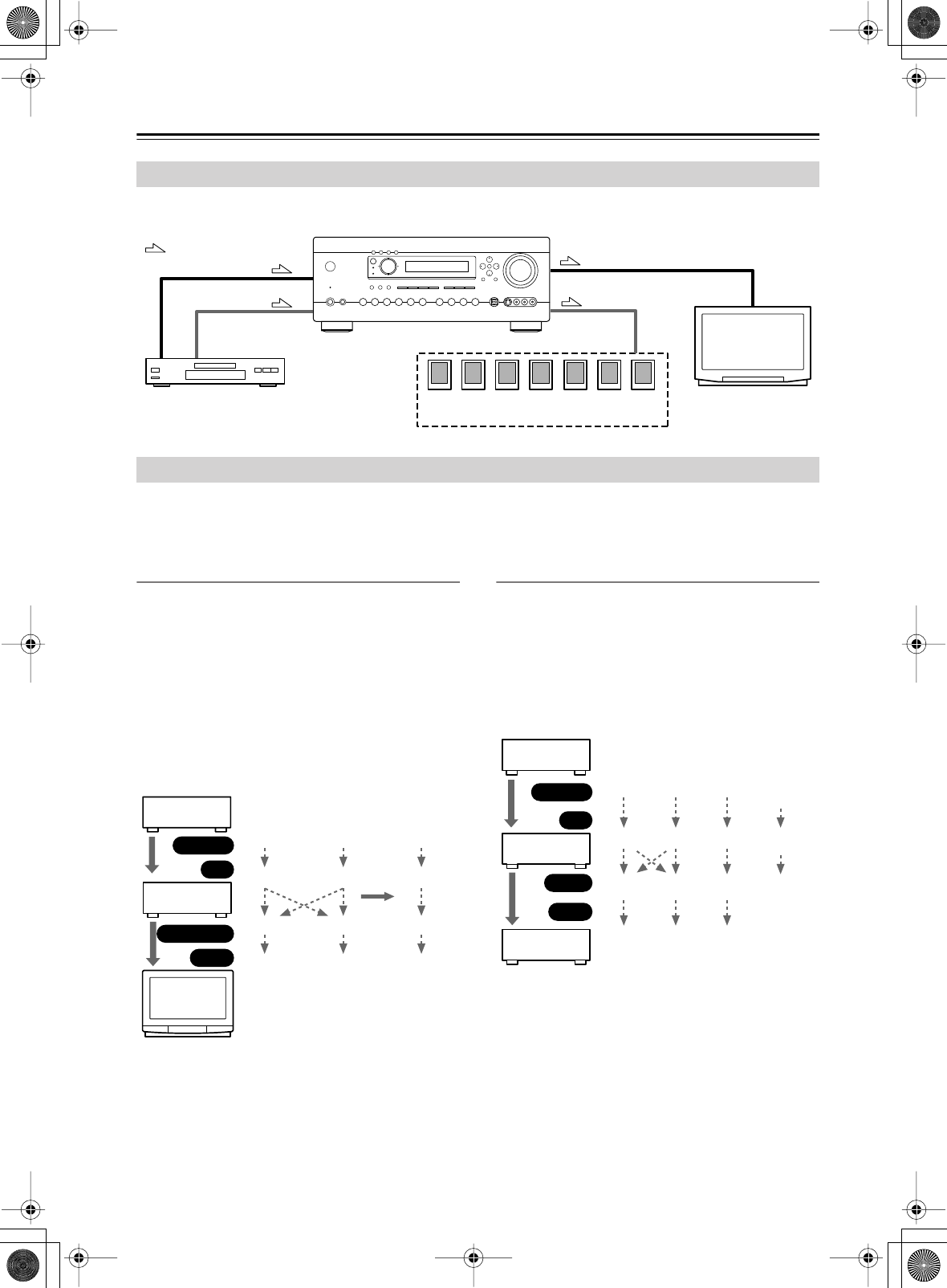
By connecting both the audio and video outputs of your DVD player and other AV components to the AV receiver, you
can select both the audio and video simultaneously simply by selecting the appropriate input source on the AV receiver.
The AV receiver supports several connection formats for compatibility with a wide range of AV equipment. The format
you choose will depend on the formats supported by your other components. Use the following sections as a guide.
For video components, you must make two connections—one for audio, one for video.
Video Connection Formats
Video equipment can be connected to the AV receiver by
using any one of the following video connection formats:
composite video, S-Video, or component video, the
latter offering the best picture quality.
A video signal connected to a V or S IN jack will be con-
verted—composite video to S-Video or S-Video to com-
posite video—but only for the MONITOR OUT jacks,
not the VIDEO 1 and VIDEO 2 OUT V and S jacks.
Note:
The DTR-6.5/5.5 can be set to upconvert com-
posite video and S-Video input signals and output them
from the COMPONENT VIDEO OUT (see page 43).
Audio Connection Formats
Audio equipment can be connected to the AV receiver by
using any of the following audio connection formats:
analog, optical, coaxial, or multichannel.
When choosing a connection format, bear in mind that
the AV receiver doesn’t convert between them. For
example, audio signals connected to an OPTICAL or
COAXIAL input are not output by the analog TAPE
OUT.
Connecting Both Audio & Video
: Signal Flow
Video
Audio
Video
Audio
Speakers (see page 23 for connection
information)
DVD player, etc.
TV, projector,
etc.
Which Connections Should I Use?
DVD player,
etc.
AV Receiver
TV, pro-
jector,
etc.
Composite
Output
IN
MONITOR OUT
Input
Composite
Composite
Composite
S-Video
S-Video
S-Video
S-Video
Component
Component
Component
Component
page 43 *
DVD player,
etc.
AV Receiver
MD recorder,
etc.
Optical
Output
IN
OUT
Input
Optical
Optical
Coaxial
Coaxial
Coaxial *
* DTR-6.5 only
Analog
Analog
Analog
Multi-
channel
Multi-
channel
Only front
left and
right
Optical Coaxial Analog
DTR-6.5,5.5_En.book Page 26 Wednesday, July 28, 2004 9:07 AM
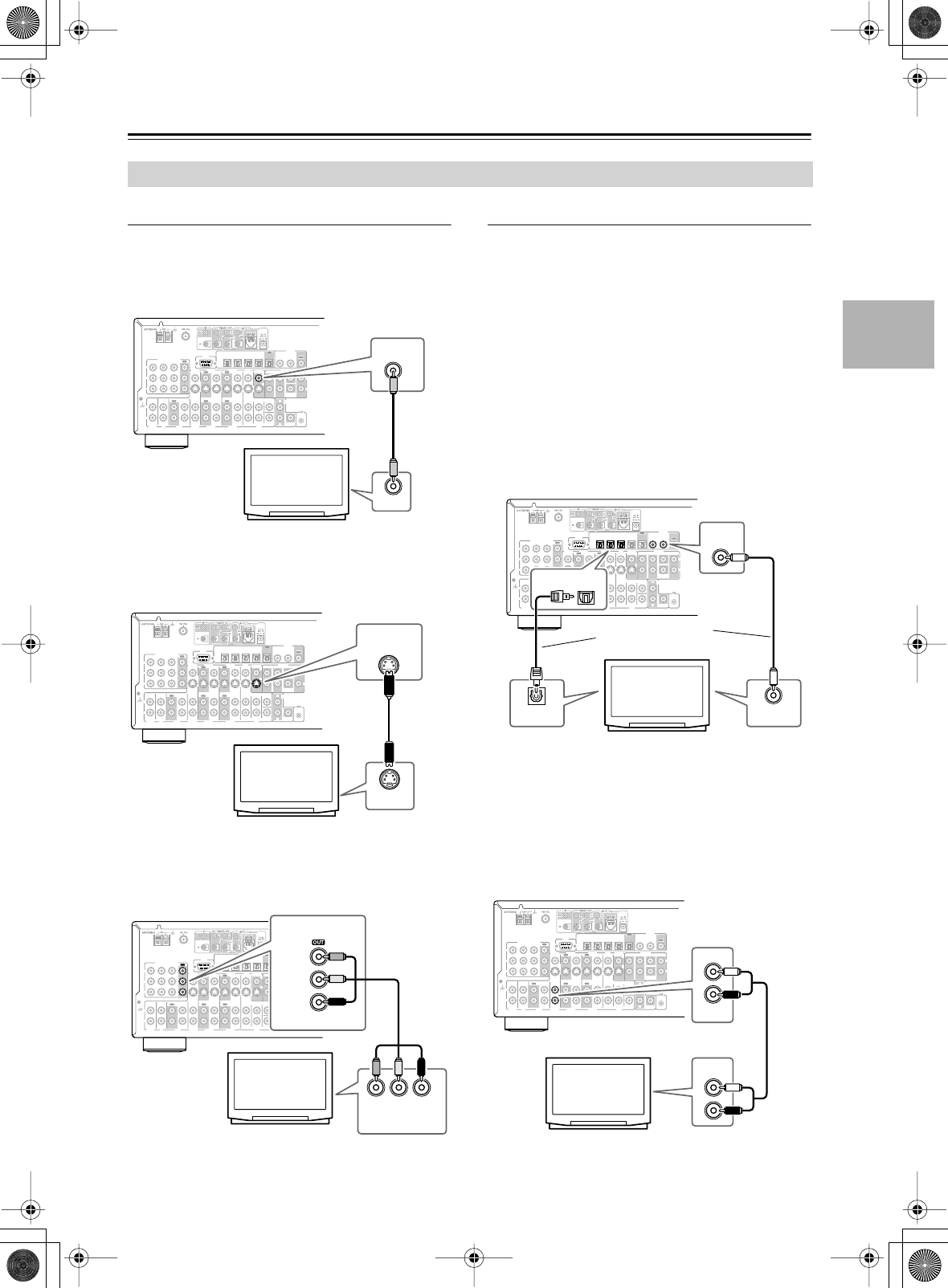
27
Connecting the AV receiver
—Continued
Monitor Out
■
Using Composite Video
Use a composite video cable to connect the AV receiver’s
V MONITOR OUT jack to a composite video input on
your TV, as shown.
■
Using S-Video
Use an S-Video cable to connect the AV receiver’s
S MONITOR OUT jack to an S-Video input on your TV,
as shown.
■
Using Component Video
Use a component video cable to connect the AV
receiver’s COMPONENT VIDEO OUT jacks to a com-
ponent video input on your TV, as shown.
Audio Connections
These connections will allow you to listen to audio from
your TV via the AV receiver.
If your TV doesn’t have an audio output, connect the AV
receiver to your VCR and use its tuner (see page 30).
■
Using Coaxial or Optical Connections
If you connect to a digital audio input, you’ll need to
assign it (see page 42).
•Use an optical digital audio cable to connect one of the
AV receiver’s OPTICAL DIGITAL IN jacks to an
optical output on your TV, as shown.
OR
•Use a coaxial digital audio cable to connect one of the
AV receiver’s COAXIAL DIGITAL IN jacks to a
coaxial output on your TV, as shown.
■
Using Analog Connections
If your TV doesn’t have a digital audio output, or you
want to record from it, you’ll need to make the following
analog audio connection.
Use an analog audio cable to connect the AV receiver’s
VIDEO 3 IN L/R jacks to an analog audio output on your
TV, as shown.
Connecting Your TV or Projector
R
L
IN 1IN 2IN 3
FRONT SURR CENTER
FRONT SURR CENTER
SURR BACK
DVD
CD
VIDEO 3 VIDEO 2 VIDEO 1
VIDEO 3 VIDEO 2 PRE OUT
VIDEO 1
IN IN IN
OUT OUT IN IN
OUT
OUT
TAPE
SUB
WOOFER SUB
WOOFER
SUB
WOOFER
MONITOR
OUT
DVD
COMPONENT VIDEO
P
B
Y
P
R
IN OUT IN IN IN
OUT
R
L
R
L
REMOTE
CONTROL
ZONE 2
OUT
V
S
IN 1IN
2
OUT
OPTICAL
IN1IN2IN3IN
4
OUT
COAXIAL
DIGITAL
RS
232
R
L
PHONO
IN
GND
MONITOR
OUT
V
VIDEO IN
TV, projector,
etc.
R
L
IN 1IN 2IN 3
FRONT SURR CENTER
FRONT SURR CENTER
SURR BACK
DVD
CD
VIDEO 3 VIDEO 2 VIDEO 1
VIDEO 3 VIDEO 2 PRE OUT
VIDEO 1
IN IN IN
OUT OUT IN IN
OUT
OUT
TAPE
SUB
WOOFER SUB
WOOFER
SUB
WOOFER
MONITOR
OUT
DVD
COMPONENT VIDEO
P
B
Y
P
R
IN OUT IN IN IN
OUT
R
L
R
L
REMOTE
CONTROL
ZONE 2
OUT
V
S
IN 1IN
2
OUT
OPTICAL
IN1IN2IN3IN
4
OUT
COAXIAL
DIGITAL
RS
232
R
L
PHONO
IN
GND
MONITOR
OUT
S
S VIDEO IN
TV, projector,
etc.
R
L
IN 1IN 2IN 3
FRONT SURR CENTER
FRONT SURR CENTER
SURR BACK
DVD
CD
VIDEO 3 VIDEO 2 VIDEO 1
VIDEO 3 VIDEO 2 PRE OUT
VIDEO 1
IN IN IN
OUT OUT IN IN
OUT
OUT
TAPE
SUB
WOOFER SUB
WOOFER
SUB
WOOFER
MONITOR
OUT
DVD
COMPONENT VIDEO
P
B
Y
P
R
IN OUT IN IN IN
OUT
R
L
R
L
REMOTE
CONTROL
ZONE 2
OUT
V
S
IN 1IN
2
OUT
OPTICAL
IN1IN2IN3IN
4
OUT
COAXIAL
DIGITAL
RS
232
R
L
PHONO
IN
GND
YPBPR
COMPONENT
VIDEO IN
P
COMPONENT VIDEO
B
PR
Y
TV, projector,
etc.
R
L
IN 1IN 2IN 3
FRONT SURR CENTER
FRONT SURR CENTER
SURR BACK
DVD
CD
VIDEO 3 VIDEO 2 VIDEO 1
VIDEO 3 VIDEO 2 PRE OUT
VIDEO 1
IN IN IN
OUT OUT IN IN
OUT
OUT
TAPE
SUB
WOOFER SUB
WOOFER
SUB
WOOFER
MONITOR
OUT
DVD
COMPONENT VIDEO
P
B
Y
P
R
IN OUT IN IN IN
OUT
R
L
R
L
REMOTE
CONTROL
ZONE 2
OUT
V
S
IN 1IN
2
OUT
OPTICAL
IN1IN2IN3IN
4
OUT
COAXIAL
DIGITAL
RS
232
R
L
PHONO
IN
GND
OPTICAL
IN
COAXIAL
IN
DIGITAL OUT
OPTICAL
DIGITAL OUT
COAXIAL
TV, projector,
etc.
Connect one or the
other
R
L
IN 1IN 2IN 3
FRONT SURR CENTER
FRONT SURR CENTER
SURR BACK
DVD
CD
VIDEO 3 VIDEO 2 VIDEO 1
VIDEO 3 VIDEO 2 PRE OUT
VIDEO 1
IN IN IN
OUT OUT IN IN
OUT
OUT
TAPE
SUB
WOOFER SUB
WOOFER
SUB
WOOFER
MONITOR
OUT
DVD
COMPONENT VIDEO
P
B
Y
P
R
IN OUT IN IN IN
OUT
R
L
R
L
REMOTE
CONTROL
ZONE 2
OUT
V
S
IN 1IN
2
OUT
OPTICAL
IN1IN2IN3IN
4
OUT
COAXIAL
DIGITAL
RS
232
R
L
PHONO
IN
GND
IN
VIDEO 3
AUDIO
OUTPUT
L
R
TV, projector,
etc.
DTR-6.5,5.5_En.book Page 27 Wednesday, July 28, 2004 9:07 AM
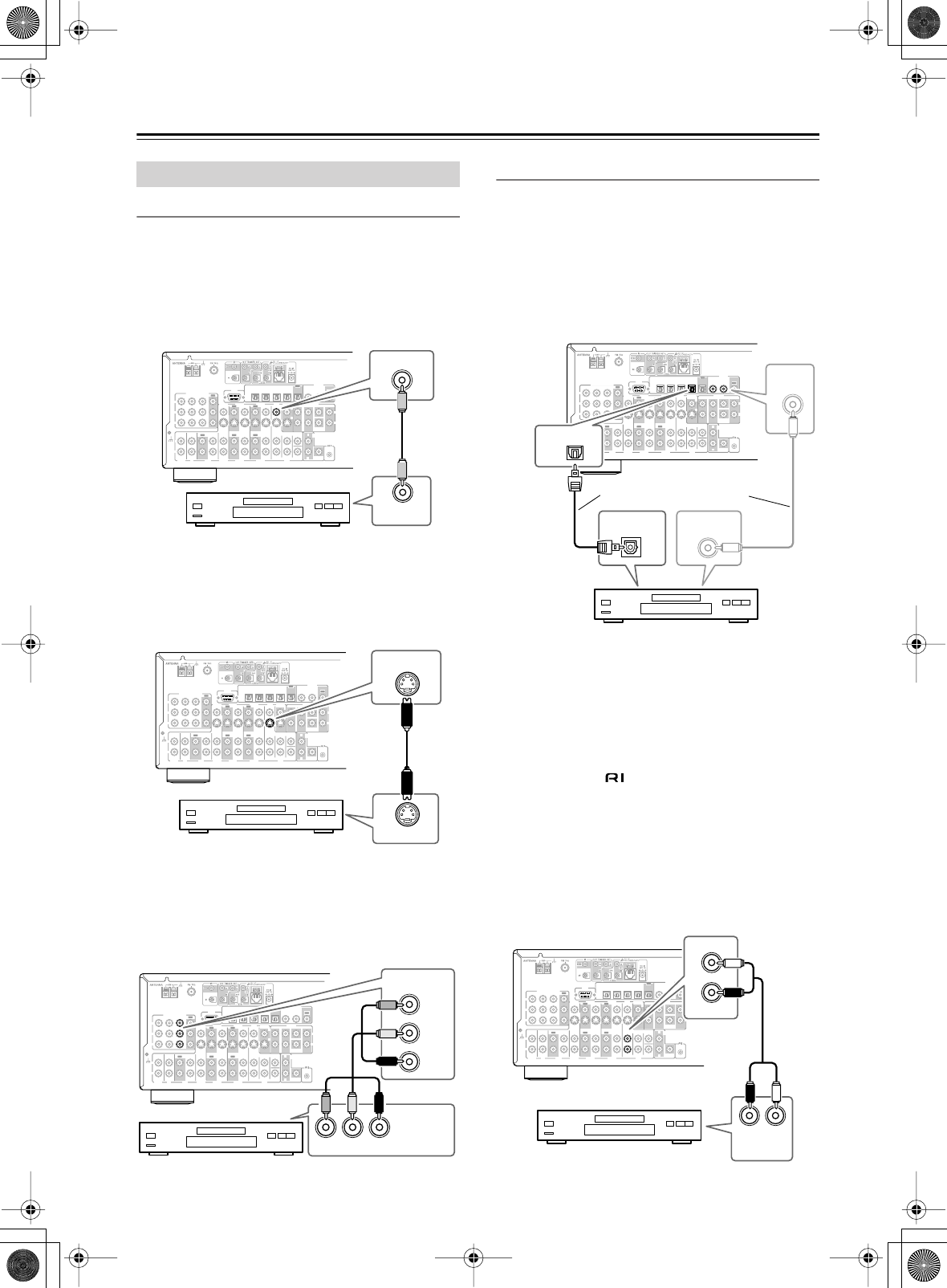
28
Connecting the AV receiver
—Continued
Video Connections
You only need to use one of the following connection
methods.
■
Using Composite Video
Use a composite video cable to connect the AV receiver’s
V DVD IN jack to the composite video output on your
DVD player, as shown.
■
Using S-Video
Use an S-Video cable to connect the AV receiver’s
S DVD IN jack to the S-Video output on your DVD
player, as shown.
■
Using Component Video
Use a component video cable to connect the AV
receiver’s COMPONENT VIDEO IN1 jacks to the com-
ponent video output on your DVD player, as shown.
•Your TV must also be connected via component video.
Audio Connections
■
Using Coaxial or Optical Connections
•Use an optical digital audio cable to connect one of the
AV receiver’s OPTICAL DIGITAL IN jacks to the
optical output on your DVD player, as shown.
OR
•Use a coaxial digital audio cable to connect one of the
AV receiver’s COAXIAL DIGITAL IN jacks to the
coaxial output on your DVD player, as shown.
Initially, the OPTICAL IN1 jack is assigned to the DVD
input source. If you connect your DVD player to a dif-
ferent digital input, you’ll need to reassign the DVD
input source (see page 42).
■
Using Analog Connections
Even if your DVD player is connected digitally (optical
or coaxial), to use , or to record audio from your
DVD player, you’ll need to make an analog connection
as well.
Use an analog audio cable to connect the AV receiver’s
DVD IN L/R jacks to the analog audio output on your
DVD player, as shown.
If your DVD player has stereo (L/R) and multichannel
outputs, be sure to use the left and right outputs.
Connecting a DVD Player
R
L
IN 1IN 2IN 3
FRONT SURR CENTER
FRONT SURR CENTER
SURR BACK
DVD
CD
VIDEO 3 VIDEO 2 VIDEO 1
VIDEO 3 VIDEO 2 PRE OUT
VIDEO 1
IN IN IN
OUT OUT IN IN
OUT
OUT
TAPE
SUB
WOOFER SUB
WOOFER
SUB
WOOFER
MONITOR
OUT
DVD
COMPONENT VIDEO
P
B
Y
P
R
IN OUT IN IN IN
OUT
R
L
R
L
REMOTE
CONTROL
ZONE 2
OUT
V
S
IN 1IN
2
OUT
OPTICAL
IN1IN2IN3IN
4
OUT
COAXIAL
DIGITAL
RS
232
R
L
PHONO
IN
GND
VIDEO OUT
IN
DVD
DVD player
R
L
IN 1IN 2IN 3
FRONT SURR CENTER
FRONT SURR CENTER
SURR BACK
DVD
CD
VIDEO 3 VIDEO 2 VIDEO 1
VIDEO 3 VIDEO 2 PRE OUT
VIDEO 1
IN IN IN
OUT OUT IN IN
OUT
OUT
TAPE
SUB
WOOFER SUB
WOOFER
SUB
WOOFER
MONITOR
OUT
DVD
COMPONENT VIDEO
P
B
Y
P
R
IN OUT IN IN IN
OUT
R
L
R
L
REMOTE
CONTROL
ZONE 2
OUT
V
S
IN 1IN
2
OUT
OPTICAL
IN1IN2IN3IN
4
OUT
COAXIAL
DIGITAL
RS
232
R
L
PHONO
IN
GND
S VIDEO OUT
DVD
IN
DVD player
R
L
IN 1IN 2IN 3
FRONT SURR CENTER
FRONT SURR CENTER
SURR BACK
DVD
CD
VIDEO 3 VIDEO 2 VIDEO 1
VIDEO 3 VIDEO 2 PRE OUT
VIDEO 1
IN IN IN
OUT OUT IN IN
OUT
OUT
TAPE
SUB
WOOFER SUB
WOOFER
SUB
WOOFER
MONITOR
OUT
DVD
COMPONENT VIDEO
P
B
Y
P
R
IN OUT IN IN IN
OUT
R
L
R
L
REMOTE
CONTROL
ZONE 2
OUT
V
S
IN 1IN
2
OUT
OPTICAL
IN1IN2IN3IN
4
OUT
COAXIAL
DIGITAL
RS
232
R
L
PHONO
IN
GND
COMPONENT
VIDEO OUT
COMPONENT VIDEO
IN1
Y
PB
PR
YPBPR
DVD player
R
L
IN 1IN 2IN 3
FRONT SURR CENTER
FRONT SURR CENTER
SURR BACK
DVD
CD
VIDEO 3 VIDEO 2 VIDEO 1
VIDEO 3 VIDEO 2 PRE OUT
VIDEO 1
IN IN IN
OUT OUT IN IN
OUT
OUT
TAPE
SUB
WOOFER SUB
WOOFER
SUB
WOOFER
MONITOR
OUT
DVD
COMPONENT VIDEO
P
B
Y
P
R
IN OUT IN IN IN
OUT
R
L
R
L
REMOTE
CONTROL
ZONE 2
OUT
V
S
IN 1IN
2
OUT
OPTICAL
IN1IN2IN3IN
4
OUT
COAXIAL
DIGITAL
RS
232
R
L
PHONO
IN
GND
DIGITAL
IN
COAXIAL
DIGITAL OUT
OPTICAL
DIGITAL OUT
COAXIAL
OPTICAL
IN1
Connect one or the other
DVD player
R
L
IN 1IN 2IN 3
FRONT SURR CENTER
FRONT SURR CENTER
SURR BACK
DVD
CD
VIDEO 3 VIDEO 2 VIDEO 1
VIDEO 3 VIDEO 2 PRE OUT
VIDEO 1
IN IN IN
OUT OUT IN IN
OUT
OUT
TAPE
SUB
WOOFER SUB
WOOFER
SUB
WOOFER
MONITOR
OUT
DVD
COMPONENT VIDEO
P
B
Y
P
R
IN OUT IN IN IN
OUT
R
L
R
L
REMOTE
CONTROL
ZONE 2
OUT
V
S
IN 1IN
2
OUT
OPTICAL
IN1IN2IN3IN
4
OUT
COAXIAL
DIGITAL
RS
232
R
L
PHONO
IN
GND
LR
AUDIO
OUTPUT
L
R
DVD
FRONT
DVD player
DTR-6.5,5.5_En.book Page 28 Wednesday, July 28, 2004 9:07 AM
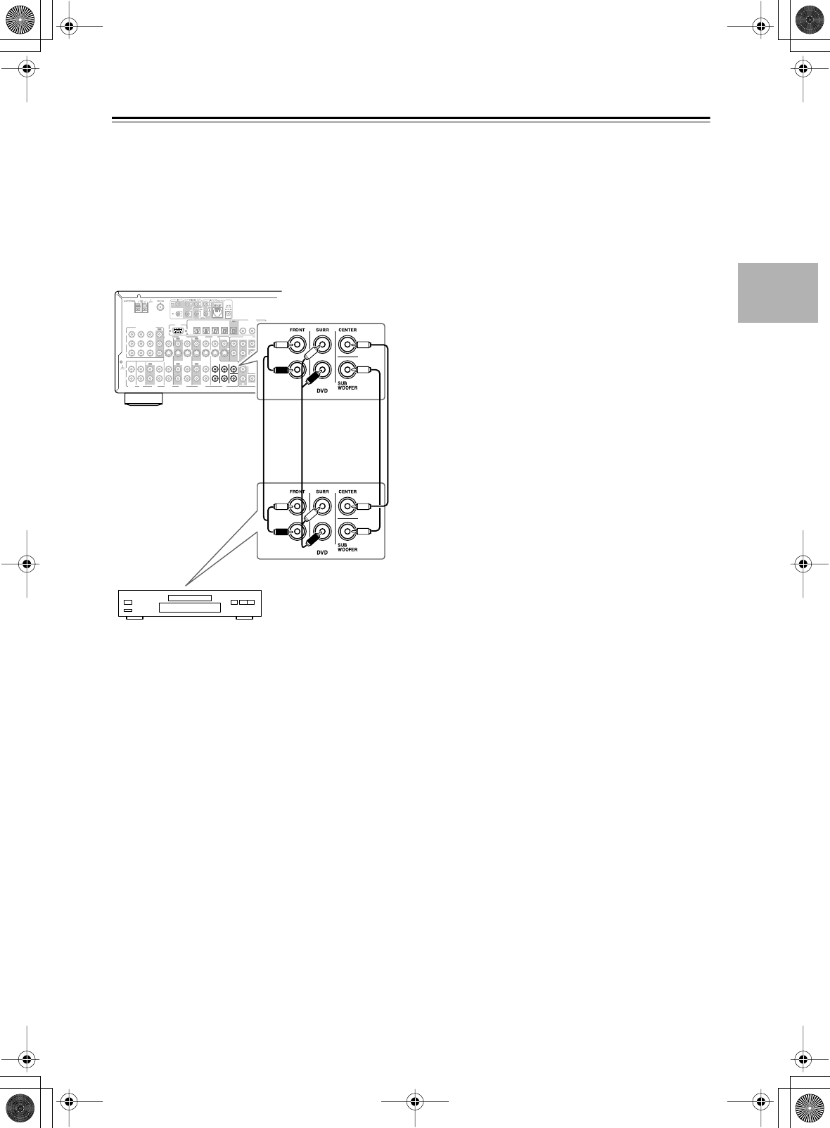
29
Connecting the AV receiver
—Continued
■
Using a Multichannel Connection
If your DVD player supports multichannel audio formats
such as DVD-Audio, and it has a 5.1-channel analog
audio output, you can enjoy DVD-Audio playback.
Use a multichannel analog audio cable to connect the AV
receiver’s DVD IN FRONT L/R, CENTER, SURR L/R,
and SUBWOOFER jacks to the 5.1-channel analog
audio output on your DVD player, as shown. Alterna-
tively, use several analog audio cables.
R
L
IN 1IN 2IN 3
FRONT SURR CENTER
FRONT SURR CENTER
SURR BACK
DVD
CD
VIDEO 3 VIDEO 2 VIDEO 1
VIDEO 3 VIDEO 2 PRE OUT
VIDEO 1
IN IN IN
OUT OUT IN IN
OUT
OUT
TAPE
SUB
WOOFER SUB
WOOFER
SUB
WOOFER
MONITOR
OUT
DVD
COMPONENT VIDEO
P
B
Y
P
R
IN OUT IN IN IN
OUT
R
L
R
L
REMOTE
CONTROL
ZONE 2
OUT
V
S
IN 1IN
2
OUT
OPTICAL
IN1IN2IN3IN
4
OUT
COAXIAL
DIGITAL
RS
232
R
L
PHONO
IN
GND
DVD player
DTR-6.5,5.5_En.book Page 29 Wednesday, July 28, 2004 9:07 AM
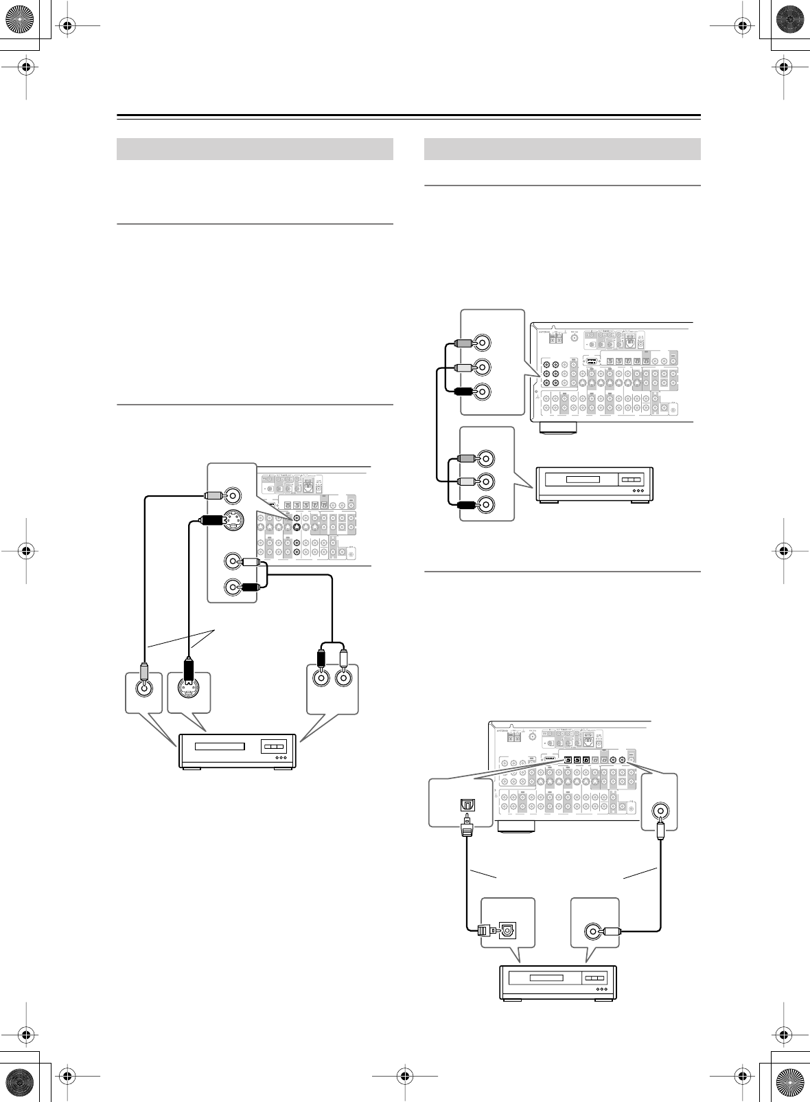
30
Connecting the AV receiver
—Continued
This section shows how to connect a VCR for playback
so that you can watch videos via the AV receiver.
Video Connections
• Use an S-Video cable to connect the AV receiver’s
S VIDEO 1 IN jack to a S-Video output on your VCR,
as shown.
OR
• Use a composite video cable to connect the AV
receiver’s V VIDEO 1 IN jack to a composite video
output on your VCR, as shown.
An S-Video connection provides better picture quality
than a composite video connection.
Audio Connections
•Use an analog audio cable to connect the AV receiver’s
VIDEO 1 IN L/R jacks to an analog audio output on
your VCR, as shown.
Video Connections
If you connect to a component video input, you must
assign it (see page 43).
Use a component video cable to connect the AV
receiver’s COMPONENT VIDEO IN2 or 3 jacks to a
component video output on your D-VHS VCR, as
shown.
Your TV must also be connected via component video.
Audio Connections
If you connect to a digital audio input, you'll need to
assign it (see page 42).
•Use an optical digital audio cable to connect one of the
AV receiver’s OPTICAL DIGITAL IN jacks to an
optical output on your D-VHS VCR, as shown.
OR
•Use a coaxial digital audio cable to connect one of the
AV receiver’s COAXIAL DIGITAL IN jacks to a
coaxial output on your D-VHS VCR, as shown.
Connecting a VCR for Playback
R
L
IN 1IN 2IN 3
FRONT SURR CENTER
FRONT SURR CENTER
SURR BACK
DVD
CD
VIDEO 3 VIDEO 2 VIDEO 1
VIDEO 3 VIDEO 2 PRE OUT
VIDEO 1
IN IN IN
OUT OUT IN IN
OUT
OUT
TAPE
SUB
WOOFER SUB
WOOFER
SUB
WOOFER
MONITOR
OUT
DVD
COMPONENT VIDEO
P
B
Y
P
R
IN OUT IN IN IN
OUT
R
L
R
L
REMOTE
CONTROL
ZONE 2
OUT
V
S
IN 1IN
2
OUT
OPTICAL
IN1IN2IN3IN
4
OUT
COAXIAL
DIGITAL
RS
232
R
L
PHONO
IN
GND
VIDEO 1
LR
S VIDEO OUT
VIDEO OUT AUDIO
OUTPUT
IN
IN
L
R
VCR
Connect one
or the other
Connecting a D-VHS VCR for Playback
R
L
IN 1IN 2IN 3
FRONT SURR CENTER
FRONT SURR CENTER
SURR BACK
DVD
CD
VIDEO 3 VIDEO 2 VIDEO 1
VIDEO 3 VIDEO 2 PRE OUT
VIDEO 1
IN IN IN
OUT OUT IN IN
OUT
OUT
TAPE
SUB
WOOFER SUB
WOOFER
SUB
WOOFER
MONITOR
OUT
DVD
COMPONENT VIDEO
P
B
Y
P
R
IN OUT IN IN IN
OUT
R
L
R
L
REMOTE
CONTROL
ZONE 2
OUT
V
S
IN 1IN
2
OUT
OPTICAL
IN1IN2IN3IN
4
OUT
COAXIAL
DIGITAL
RS
232
R
L
PHONO
IN
GND
IN
Y
PB
PR
COMPONENT
VIDEO OUT
COMPONENT VIDEO
Y
PB
PR
D-VHS VCR
R
L
IN 1IN 2IN 3
FRONT SURR CENTER
FRONT SURR CENTER
SURR BACK
DVD
CD
VIDEO 3 VIDEO 2 VIDEO 1
VIDEO 3 VIDEO 2 PRE OUT
VIDEO 1
IN IN IN
OUT OUT IN IN
OUT
OUT
TAPE
SUB
WOOFER SUB
WOOFER
SUB
WOOFER
MONITOR
OUT
DVD
COMPONENT VIDEO
P
B
Y
P
R
IN OUT IN IN IN
OUT
R
L
R
L
REMOTE
CONTROL
ZONE 2
OUT
V
S
IN 1IN
2
OUT
OPTICAL
IN1IN2IN3IN
4
OUT
COAXIAL
DIGITAL
RS
232
R
L
PHONO
IN
GND
DIGIT
IN
COAXIAL
DIGITAL OUT
OPTICAL DIGITAL OUT
COAXIAL
AL
OPTICAL
IN
D-VHS VCR
Connect one or the other
DTR-6.5,5.5_En.book Page 30 Wednesday, July 28, 2004 9:07 AM
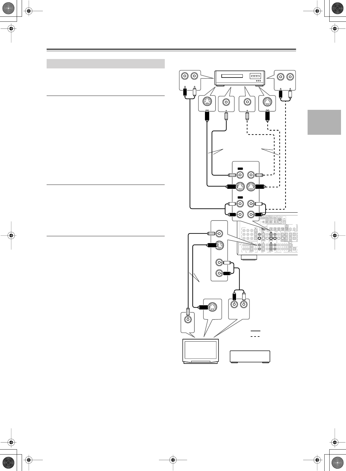
31
Connecting the AV receiver
—Continued
This section explains how to connect a VCR for
recording from a TV or another VCR.
Video Connections
• Use an S-Video cable to connect the AV receiver’s
S VIDEO 1 OUT jack to an S-Video input on the
recording VCR. Use another S-Video cable to connect
the AV receiver’s S VIDEO 3 IN jack to an S-Video
output on your TV or playback VCR, as shown.
OR
• Use a composite video cable to connect the AV
receiver’s V VIDEO 1 OUT jack to a composite video
input on the recording VCR. Use another composite
video cable to connect the AV receiver’s V VIDEO 3
IN jack to a composite video output on your TV or
playback VCR, as shown.
Audio Connections
•Use an analog audio cable to connect the AV receiver’s
VIDEO 1 OUT L/R jacks to an audio input on the
recording VCR.
•Use an analog audio cable to connect the AV receiver’s
VIDEO 3 IN L/R jacks to an audio output on your TV
or playback VCR.
Playback from the Recording VCR
To play back a video in the recording VCR via the AV
receiver:
• Use an S-Video cable to connect the AV receiver’s S
VIDEO 1 IN jack to an S-Video output on the record-
ing VCR.
OR
• Use a composite video cable to connect the AV
receiver’s V VIDEO 1 IN jack to a composite video
output on the recording VCR. And use an analog audio
cable to connect the AV receiver’s VIDEO 1 IN L/R
jacks to an audio output on the recording VCR.
Notes:
• The AV receiver must be turned on for recording.
Recording is not possible while it’s in Standby mode.
• If you want to record directly from your TV or play-
back VCR to the recording VCR without going
through the AV receiver, connect the TV/VCR’s audio
and video outputs directly to the recording VCR’s
audio and video inputs. See the manuals supplied with
your TV and VCR for details.
•Video signals connected to composite video inputs
can only be recorded via composite video outputs. If
your TV/VCR is connected to a composite video
input, the recording VCR must be connected to a com-
posite video output. Similarly, video signals con-
nected to S-Video inputs can only be recorded via
S-Video outputs. If your TV/VCR is connected to an
S-Video input, the recording VCR must be connected
to an S-Video output.
Connecting a VCR for Recording
R
L
IN 1IN 2IN 3
FRONT SURR CENTER
FRONT SURR CENTER
SUR
R
DVD
CD
VIDEO 3 VIDEO 2 VIDEO 1
VIDEO 3 VIDEO 2 PRE OUT
VIDEO 1
IN IN IN
OUT OUT IN IN
OUT
OUT
TAPE
SUB
WOOFER SUB
WOOFER
SUB
WOOFER
MONITOR
OUT
DVD
COMPONENT VIDEO
P
B
Y
P
R
IN OUT IN IN IN
OUT
R
L
RE
M
CO
N
ZONE 2
OUT
V
S
IN 1IN
2
O
OPTICAL
IN1IN2IN3IN
4
OUT
COAXIAL
DIGITAL
RS
232
R
L
PHONO
IN
GND
VIDEO
OUT
S VIDEO
OUT
LR
AUDIO
OUTPUT
LR
S VIDEO IN VIDEO IN
AUDIO
INPUT
LR
S VIDEO OUT
VIDEO OUT
AUDIO
OUTPUT
L
R
IN
IN
VIDEO 3
OUT
OUT
VIDEO 1
IN
IN
:
:
TV
VCR (recording)
Connect one
or the other
Connect one or
the other
For recording
For playback
VCR, etc.or
DTR-6.5,5.5_En.book Page 31 Wednesday, July 28, 2004 9:07 AM
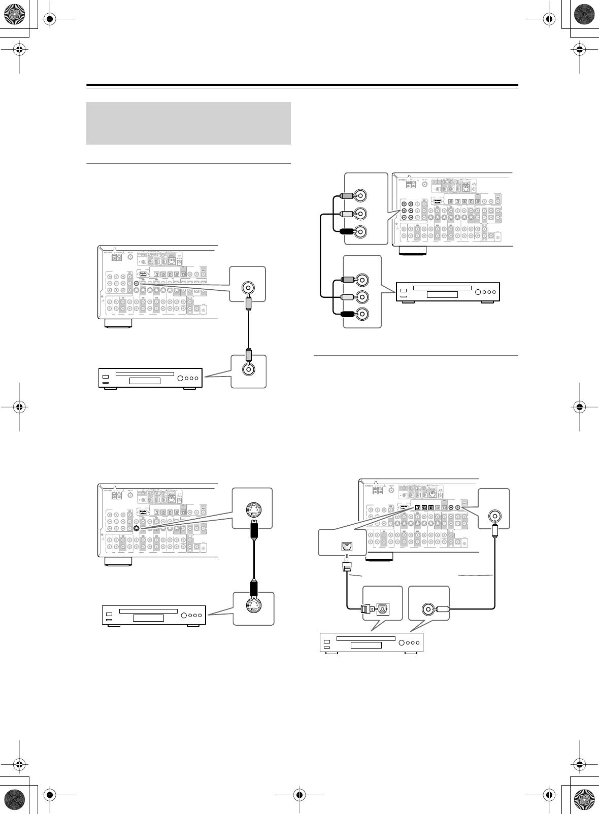
32
Connecting the AV receiver
—Continued
Video Connections
You only need to use one of the following connection
methods.
■
Using Composite Video
Use a composite video cable to connect the AV receiver’s
V VIDEO 3 IN jack to a composite video output on your
video source, as shown.
■
Using S-Video
Use an S-Video cable to connect the AV receiver’s
S VIDEO 3 IN jack to an S-Video output on your video
source, as shown.
■
Using Component Video
If you connect to a component video input, you must
assign it (see page 43).
Use a component video cable to connect the AV
receiver’s COMPONENT VIDEO IN 2 or IN 3 jack to a
component video output on your video source, as shown.
Audio Connections
■
Using Optical or Coaxial Connections
If you connect to a digital audio input, you’ll need to
assign it (see page 42).
•Use an optical digital audio cable to connect one of the
AV receiver’s OPTICAL DIGITAL IN jacks to an
optical output on your video source, as shown.
OR
•Use a coaxial digital audio cable to connect one of the
AV receiver’s COAXIAL DIGITAL IN jacks to a
coaxial output on your video source, as shown.
Notes:
•To connect the AV receiver to an LD player’s AC-3RF
output, you need a commercially available demodula-
tor.
Connecting Other Video Sources—
Satellite, Cable, Set-top box, LD
Player, etc.
R
L
IN 1IN 2IN 3
FRONT SURR CENTER
FRONT SURR CENTER
SURR BACK
DVD
CD
VIDEO 3 VIDEO 2 VIDEO 1
VIDEO 3 VIDEO 2 PRE OUT
VIDEO 1
IN IN IN
OUT OUT IN IN
OUT
OUT
TAPE
SUB
WOOFER SUB
WOOFER
SUB
WOOFER
MONITOR
OUT
DVD
COMPONENT VIDEO
P
B
Y
P
R
IN OUT IN IN IN
OUT
R
L
R
L
REMOTE
CONTROL
ZONE 2
OUT
V
S
IN 1IN
2
OUT
OPTICAL
IN1IN2IN3IN
4
OUT
COAXIAL
DIGITAL
RS
232
R
L
PHONO
IN
GND
VIDEO OUT
IN
VIDEO 3
Satellite, cable, set-top
box, LD player, etc.
R
L
IN 1IN 2IN 3
FRONT SURR CENTER
FRONT SURR CENTER
SURR BACK
DVD
CD
VIDEO 3 VIDEO 2 VIDEO 1
VIDEO 3 VIDEO 2 PRE OUT
VIDEO 1
IN IN IN
OUT OUT IN IN
OUT
OUT
TAPE
SUB
WOOFER SUB
WOOFER
SUB
WOOFER
MONITOR
OUT
DVD
COMPONENT VIDEO
P
B
Y
P
R
IN OUT IN IN IN
OUT
R
L
R
L
REMOTE
CONTROL
ZONE 2
OUT
V
S
IN 1IN
2
OUT
OPTICAL
IN1IN2IN3IN
4
OUT
COAXIAL
DIGITAL
RS
232
R
L
PHONO
IN
GND
S VIDEO OUT
VIDEO 3
IN
Satellite, cable, set-top
box, LD player, etc.
R
L
IN 1IN 2IN 3
FRONT SURR CENTER
FRONT SURR CENTER
SURR BACK
DVD
CD
VIDEO 3 VIDEO 2 VIDEO 1
VIDEO 3 VIDEO 2 PRE OUT
VIDEO 1
IN IN IN
OUT OUT IN IN
OUT
OUT
TAPE
SUB
WOOFER SUB
WOOFER
SUB
WOOFER
MONITOR
OUT
DVD
COMPONENT VIDEO
P
B
Y
P
R
IN OUT IN IN IN
OUT
R
L
R
L
REMOTE
CONTROL
ZONE 2
OUT
V
S
IN 1IN
2
OUT
OPTICAL
IN1IN2IN3IN
4
OUT
COAXIAL
DIGITAL
RS
232
R
L
PHONO
IN
GND
COMPONENT
VIDEO OUT
IN
Y
PB
PR
Y
PB
PR
COMPONENT VIDEO
Satellite, cable, set-top
box, LD player, etc.
R
L
IN 1IN 2IN 3
FRONT SURR CENTER
FRONT SURR CENTER
SURR BACK
DVD
CD
VIDEO 3 VIDEO 2 VIDEO 1
VIDEO 3 VIDEO 2 PRE OUT
VIDEO 1
IN IN IN
OUT OUT IN IN
OUT
OUT
TAPE
SUB
WOOFER SUB
WOOFER
SUB
WOOFER
MONITOR
OUT
DVD
COMPONENT VIDEO
P
B
Y
P
R
IN OUT IN IN IN
OUT
R
L
R
L
REMOTE
CONTROL
ZONE 2
OUT
V
S
IN 1IN
2
OUT
OPTICAL
IN1IN2IN3IN
4
OUT
COAXIAL
DIGITAL
RS
232
R
L
PHONO
IN
GND
OPTICAL
IN
DIGITAL
IN
COAXIAL
DIGITAL OUT
OPTICAL
DIGITAL OUT
COAXIAL
Satellite, cable, set-top box, LD player, etc.
Connect one or the other
DTR-6.5,5.5_En.book Page 32 Wednesday, July 28, 2004 9:07 AM
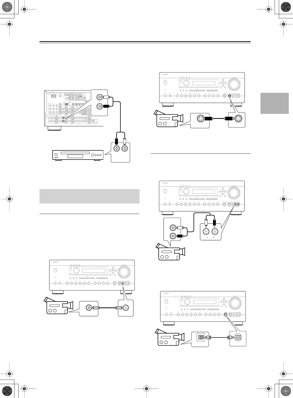
33
Connecting the AV receiver
—Continued
■
Using Analog Connections
If your video source doesn’t have a digital audio output,
or you want to record from it, you’ll need to make the
following analog audio connection.
Use an analog audio cable to connect the AV receiver’s
VIDEO 3 IN L/R jacks to the analog audio output on
your video source, as shown.
Video Connections
You only need to use one of the following connection
methods.
■
Using Composite Video
Use a composite video cable to connect the AV receiver’s
VIDEO 4 INPUT VIDEO jack to the composite video
output on your camcorder, games console, etc., as
shown.
■
Using S-Video
Use an S-Video cable to connect the AV receiver’s
VIDEO 4 INPUT S VIDEO jack to the S-Video output
on your camcorder, games console, etc., as shown.
Audio Connections
Use an analog audio cable to connect the AV receiver’s
VIDEO 4 INPUT AUDIO L/R jacks to the analog audio
output on your camcorder, games console, etc., as
shown.
If your camcorder, games console, etc., has an optical
digital audio output, use an optical digital audio cable to
connect it to the AV receiver’s VIDEO 4 INPUT DIG-
ITAL jack, as shown.
Connecting a Camcorder, Games
Console, etc.
R
L
IN 1IN 2IN 3
FRONT SURR CENTER
FRONT SURR CENTER
SURR BACK
DVD
CD
VIDEO 3 VIDEO 2 VIDEO 1
VIDEO 3 VIDEO 2 PRE OUT
VIDEO 1
IN IN IN
OUT OUT IN IN
OUT
OUT
TAPE
SUB
WOOFER SUB
WOOFER
SUB
WOOFER
MONITOR
OUT
DVD
COMPONENT VIDEO
P
B
Y
P
R
IN OUT IN IN IN
OUT
R
L
R
L
REMOTE
CONTROL
ZONE 2
OUT
V
S
IN 1IN
2
OUT
OPTICAL
IN1IN2IN3IN
4
OUT
COAXIAL
DIGITAL
RS
232
R
L
PHONO
IN
GND
LR
L
R
AUDIO
OUTPUT
IN
VIDEO 3
Satellite, cable, set-top
box, LD player, etc.
Standby
Zone 2
VIDEO OUT
Video
Camcorder,
games console, etc.
Standby
Zone 2
S VIDEO OUT S Video
Camcorder,
games console, etc.
Standby
Zone 2
Audio
LR
L
R
AUDIO
OUTPUT
Camcorder,
games console, etc.
Standby
Zone 2
DIGITAL OUT
Digital
Camcorder,
games console, etc.
DTR-6.5,5.5_En.book Page 33 Wednesday, July 28, 2004 9:07 AM
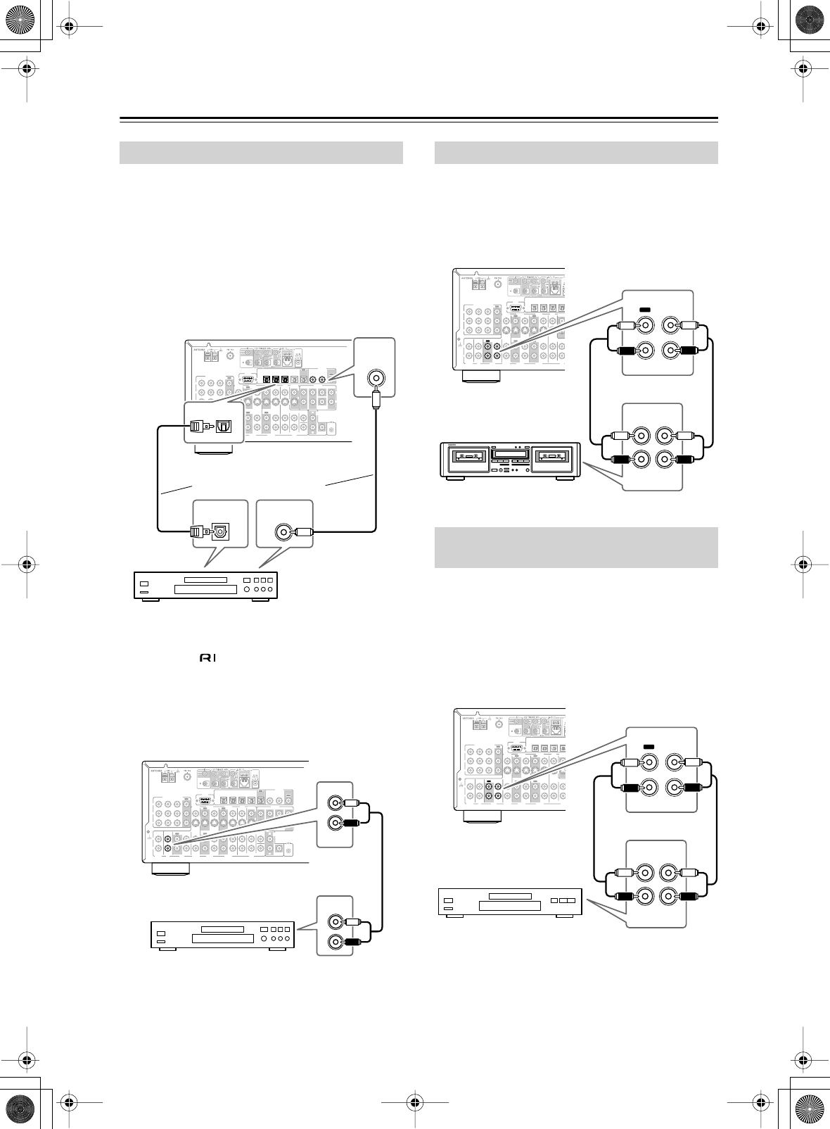
34
Connecting the AV receiver
—Continued
■
Using Optical or Coaxial Connections
If you connect to a digital audio input, you’ll need to
assign it (see page 42).
•Use an optical digital audio cable to connect one of the
AV receiver’s OPTICAL DIGITAL IN jacks to the
optical output on your CD player, as shown.
OR
•Use a coaxial digital audio cable to connect one of the
AV receiver’s COAXIAL DIGITAL IN jacks to the
coaxial output on your CD player, as shown.
■
Using Analog Connections
Even if your CD player is connected digitally (coaxial or
optical), to use , or to record audio from your CD
player, you’ll need to make an analog audio connection
as well.
Use an analog audio cable to connect the AV receiver’s
CD IN L/R jacks to the analog audio output on your CD
player, as shown.
Use an analog audio cable to connect the AV receiver’s
TAPE IN L/R jacks to the cassette recorder’s output, and
use another analog audio cable to connect the AV
receiver’s TAPE OUT L/R jacks to the cassette
recorder’s input, as shown.
You can connect a DAT, CD, or MD recorder instead of
a cassette recorder.
■
Analog Connections
Use an analog audio cable to connect the AV receiver’s
TAPE IN L/R jacks to the recorder’s output, and use
another analog audio cable to connect the AV receiver’s
TAPE OUT L/R jacks to the recorder’s input, as shown.
Connecting a CD Player
R
L
IN 1IN 2IN 3
FRONT SURR CENTER
FRONT SURR CENTER
SURR BACK
DVD
CD
VIDEO 3 VIDEO 2 VIDEO 1
VIDEO 3 VIDEO 2 PRE OUT
VIDEO 1
IN IN IN
OUT OUT IN IN
OUT
OUT
TAPE
SUB
WOOFER SUB
WOOFER
SUB
WOOFER
MONITOR
OUT
DVD
COMPONENT VIDEO
P
B
Y
P
R
IN OUT IN IN IN
OUT
R
L
R
L
REMOTE
CONTROL
ZONE 2
OUT
V
S
IN 1IN
2
OUT
OPTICAL
IN1IN2IN3IN
4
OUT
COAXIAL
DIGITAL
RS
232
R
L
PHONO
IN
GND
OPTICAL
IN
DIGITAL
IN
COAXIAL
DIGITAL OUT
OPTICAL
DIGITAL OUT
COAXIAL
CD player
Connect one or the other
R
L
IN 1IN 2IN 3
FRONT SURR CENTER
FRONT SURR CENTER
SURR BACK
DVD
CD
VIDEO 3 VIDEO 2 VIDEO 1
VIDEO 3 VIDEO 2 PRE OUT
VIDEO 1
IN IN IN
OUT OUT IN IN
OUT
OUT
TAPE
SUB
WOOFER SUB
WOOFER
SUB
WOOFER
MONITOR
OUT
DVD
COMPONENT VIDEO
P
B
Y
P
R
IN OUT IN IN IN
OUT
R
L
R
L
REMOTE
CONTROL
ZONE 2
OUT
V
S
IN 1IN
2
OUT
OPTICAL
IN1IN2IN3IN
4
OUT
COAXIAL
DIGITAL
RS
232
R
L
PHONO
IN
GND
IN
CD
AUDIO
OUTPUT
L
R
CD player
Connecting a Cassette Recorder
Connecting a DAT, CD, or MD
Recorder
R
L
IN 1IN 2IN 3
FRONT SURR CENTER
FRONT SURR CENTER
SURR BACK
DVD
CD
VIDEO 3 VIDEO 2 VIDEO 1
VIDEO 3 VIDEO 2 PRE OUT
VIDEO 1
IN IN IN
OUT OUT IN IN
OUT
OUT
TAPE
SUB
WOOFER SUB
WOOFER
SUB
WOOFER
MONITOR
OUT
DVD
COMPONENT VIDEO
P
B
Y
P
R
IN OUT IN IN IN
OUT
R
L
R
L
REMOTE
CONTROL
ZONE 2
OUT
V
S
IN 1IN
2
OUT
OPTICAL
IN1IN2IN3IN
4
OUT
COAXIAL
DIGITAL
RS
232
R
L
PHONO
IN
GND
/
OUT
TAPE
R
L
R
L
R
L
R
L
IN
(IN) (OUT)
REC PLAY
Cassette recorder
R
L
IN 1IN 2IN 3
FRONT SURR CENTER
FRONT SURR CENTER
SURR BACK
DVD
CD
VIDEO 3 VIDEO 2 VIDEO 1
VIDEO 3 VIDEO 2 PRE OUT
VIDEO 1
IN IN IN
OUT OUT IN IN
OUT
OUT
TAPE
SUB
WOOFER SUB
WOOFER
SUB
WOOFER
MONITOR
OUT
DVD
COMPONENT VIDEO
P
B
Y
P
R
IN OUT IN IN IN
OUT
R
L
R
L
REMOTE
CONTROL
ZONE 2
OUT
V
S
IN 1IN
2
OUT
OPTICAL
IN1IN2IN3IN
4
OUT
COAXIAL
DIGITAL
RS
232
R
L
PHONO
IN
GND
OUT
TAPE
R
L
R
L
R
L
R
L
IN
(IN) (OUT)
REC PLAY
DAT, CD, or MD recorder
DTR-6.5,5.5_En.book Page 34 Wednesday, July 28, 2004 9:07 AM
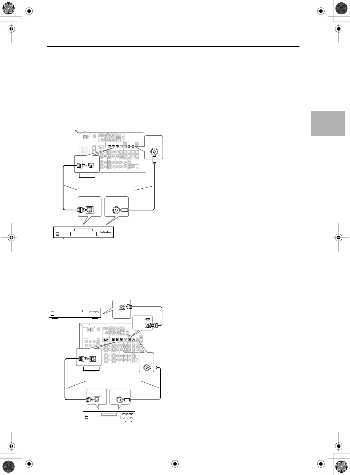
35
Connecting the AV receiver
—Continued
■
Using Optical or Coaxial Connections
(playback only)
If you connect to a digital audio input, you’ll need to
assign it (see page 42).
•Use an optical digital audio cable to connect one of the
AV receiver’s OPTICAL DIGITAL IN jacks to the
optical output on your recorder, as shown.
OR
•Use a coaxial digital audio cable to connect one of the
AV receiver’s COAXIAL DIGITAL IN jacks to the
coaxial output on your recorder, as shown.
■
Digital Recording
If your recorder has a digital input, by connecting it to
the AV receiver’s optical DIGITAL OUT jack, you can
record digitally. (With the DTR-6.5, you can use its
coaxial DIGITAL OUT jack.) However, because the AV
receiver doesn’t convert analog input signals to digital
and vice versa, only input signals connected to a DIG-
ITAL IN jack can be recorded in this way.
Note:
Don’t connect the recorder’s digital output to the AV
receiver when the recorder’s digital input is connected to
one of the AV receiver’s digital outputs. Doing so may
create a signal loop and cause a malfunction.
R
L
IN 1IN 2IN 3
FRONT SURR CENTER
FRONT SURR CENTER
SURR BACK
DVD
CD
VIDEO 3 VIDEO 2 VIDEO 1
VIDEO 3 VIDEO 2 PRE OUT
VIDEO 1
IN IN IN
OUT OUT IN IN
OUT
OUT
TAPE
SUB
WOOFER SUB
WOOFER
SUB
WOOFER
MONITOR
OUT
DVD
COMPONENT VIDEO
P
B
Y
P
R
IN OUT IN IN IN
OUT
R
L
R
L
REMOTE
CONTROL
ZONE 2
OUT
V
S
IN 1IN
2
OUT
OPTICAL
IN1IN2IN3IN
4
OUT
COAXIAL
DIGITAL
RS
232
R
L
PHONO
IN
GND
DIGITAL
IN
COAXIAL
DIGITAL OUT
OPTICAL
DIGITAL OUT
COAXIAL
OPTICAL
IN
DAT, CD, or MD
recorder
Connect one or the other
R
L
IN 1IN 2IN 3
FRONT SURR CENTER
FRONT SURR CENTER
SURR BACK
DVD
CD
VIDEO 3 VIDEO 2 VIDEO 1
VIDEO 3 VIDEO 2 PRE OUT
VIDEO 1
IN IN IN
OUT OUT IN IN
OUT
OUT
TAPE
SUB
WOOFER SUB
WOOFER
SUB
WOOFER
MONITOR
OUT
DVD
COMPONENT VIDEO
P
B
Y
P
R
IN OUT IN IN IN
OUT
R
L
R
L
REMOTE
CONTROL
ZONE 2
OUT
V
S
IN 1IN
2
OUT
OPTICAL
IN1IN2IN3IN
4
OUT
COAXIAL
DIGITAL
RS
232
R
L
PHONO
IN
GND
COAXIAL
DIGITAL
IN
OPTICAL
OPTICAL
DIGITAL OUT
COAXIAL
DIGITAL OUT
OPTICAL
DIGITAL IN
OPTICAL
IN
DAT, CD, or MD recorder
Digital source (DAT, CD, MD player)
Connect one or the other
DTR-6.5,5.5_En.book Page 35 Wednesday, July 28, 2004 9:07 AM
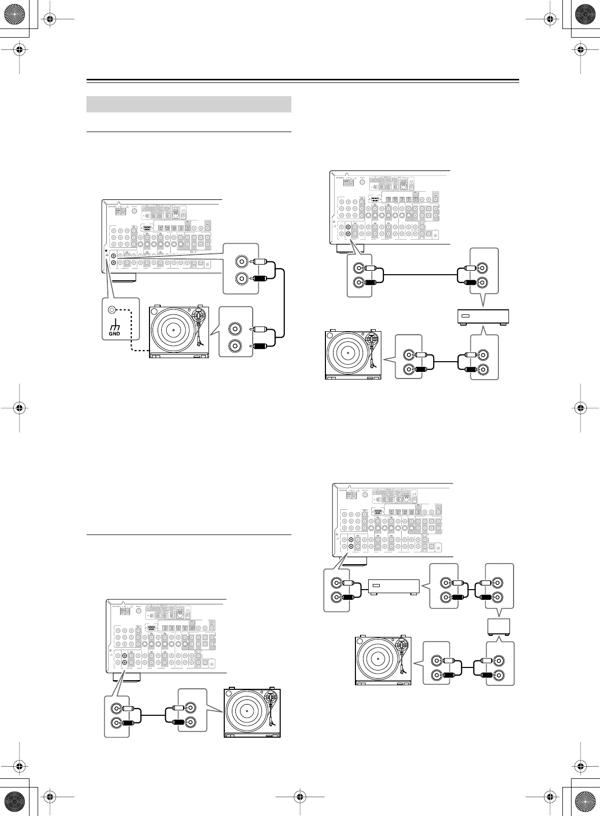
36
Connecting the AV receiver
—Continued
For the DTR-6.5
The AV receiver’s PHONO IN is designed for use with a
moving magnet (MM) type cartridge.
Use an analog audio cable to connect the AV receiver’s
PHONO IN L/R jacks to the audio output on your turn-
table, as shown.
Notes:
• If your turntable has a ground wire, connect it to the
AV receiver’s GND screw. With some turntables, con-
necting the ground wire may produce an audible hum.
If this happens, disconnected it.
• If your turntable has a moving coil (MC) type car-
tridge, you’ll need a commercially available MC head
amp or MC transformer. Connect your turntable to the
head amp or transformer, and then connect that to the
AV receiver’s PHONO IN L/R jacks.
•You can also use a phono equalizer to connect a turn-
table with an MC-type cartridge. In this case, see the
phono equalizer’s manual for details.
For the DTR-5.5
■
Turntable with a Built-in Phono Preamp
Use an analog audio cable to connect an unused audio
input on the AV receiver to the audio outputs on your
turntable, as shown.
■
Turntable without a Built-in Phono Preamp
Use an analog audio cable to connect an unused audio
input on the AV receiver to the audio outputs on your
phono preamp, and use another analog audio cable to
connect the phono preamp’s inputs to your turntable, as
shown.
■
Turntable with an MC (Moving Coil) Cartridge
Use an analog audio cable to connect an unused audio
input on the AV receiver to the audio outputs on your
phono preamp. Use another analog audio cable to con-
nect the phono preamp’s inputs to your MC head amp’s
outputs. And use another analog audio cable to connect
the MC head amp’s inputs to your turntable, as shown.
Connecting a Turntable
R
L
IN 1IN 2IN 3
FRONT SURR CENTER
FRONT SURR CENTER
SURR BACK
DVD
CD
VIDEO 3 VIDEO 2 VIDEO 1
VIDEO 3 VIDEO 2 PRE OUT
VIDEO 1
IN IN IN
OUT OUT IN IN
OUT
OUT
TAPE
SUB
WOOFER SUB
WOOFER
SUB
WOOFER
MONITOR
OUT
DVD
COMPONENT VIDEO
P
B
Y
P
R
IN OUT IN IN IN
OUT
R
L
R
L
REMOTE
CONTROL
ZONE 2
OUT
V
S
IN 1IN
2
OUT
OPTICAL
IN1IN2IN3IN
4
OUT
COAXIAL
DIGITAL
RS
232
R
L
PHONO
IN
GND
L
R
AUDIO
OUTPUT
PHONO
R
L
IN
R
L
IN 1IN 2IN 3
FRONT SURR CENTER
FRONT SURR CENTER
SURR BACK
DVD
CD
VIDEO 3 VIDEO 2 VIDEO 1
VIDEO 3 VIDEO 2 PRE OUT
VIDEO 1
IN IN IN
OUT OUT IN IN
OUT
OUT
TAPE
SUB
WOOFER SUB
WOOFER
SUB
WOOFER
MONITOR
OUT
DVD
COMPONENT VIDEO
P
B
Y
P
R
IN OUT IN IN IN
OUT
R
L
R
L
REMOTE
CONTROL
ZONE 2
OUT
V
S
IN 1IN
2
OUT
OPTICAL
IN1IN2IN3IN
4
OUT
COAXIAL
DIGITAL
RS
232
R
L
PHONO
IN
GND
IN
L
R
CD
AUDIO
OUTPUT
R
L
IN 1IN 2IN 3
FRONT SURR CENTER
FRONT SURR CENTER
SURR BACK
DVD
CD
VIDEO 3 VIDEO 2 VIDEO 1
VIDEO 3 VIDEO 2 PRE OUT
VIDEO 1
IN IN IN
OUT OUT IN IN
OUT
OUT
TAPE
SUB
WOOFER SUB
WOOFER
SUB
WOOFER
MONITOR
OUT
DVD
COMPONENT VIDEO
P
B
Y
P
R
IN OUT IN IN IN
OUT
R
L
R
L
REMOTE
CONTROL
ZONE 2
OUT
V
S
IN 1IN
2
OUT
OPTICAL
IN1IN2IN3IN
4
OUT
COAXIAL
DIGITAL
RS
232
R
L
PHONO
IN
GND
L
R
L
R
L
R
IN
CD
AUDIO
OUTPUT
AUDIO
OUTPUT
AUDIO
INPUT
Phono preamp
R
L
IN 1IN 2IN 3
FRONT SURR CENTER
FRONT SURR CENTER
SURR BACK
DVD
CD
VIDEO 3 VIDEO 2 VIDEO 1
VIDEO 3 VIDEO 2 PRE OUT
VIDEO 1
IN IN IN
OUT OUT IN IN
OUT
OUT
TAPE
SUB
WOOFER SUB
WOOFER
SUB
WOOFER
MONITOR
OUT
DVD
COMPONENT VIDEO
P
B
Y
P
R
IN OUT IN IN IN
OUT
R
L
R
L
REMOTE
CONTROL
ZONE 2
OUT
V
S
IN 1IN
2
OUT
OPTICAL
IN1IN2IN3IN
4
OUT
COAXIAL
DIGITAL
RS
232
R
L
PHONO
IN
GND
L
R
L
R
L
R
L
R
IN
CD
AUDIO
OUTPUT
AUDIO
OUTPUT
AUDIO
INPUT
AUDIO
INPUT
Phono preamp
MC head amp or
MC transformer
DTR-6.5,5.5_En.book Page 36 Wednesday, July 28, 2004 9:07 AM
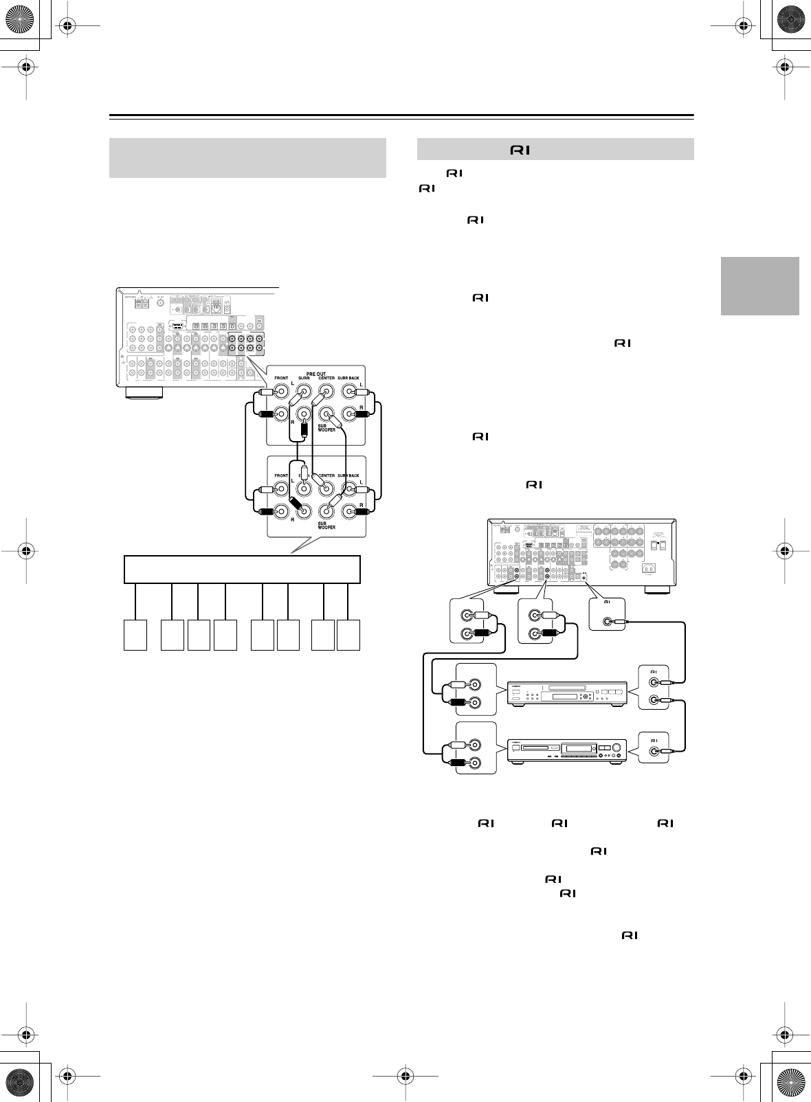
37
Connecting the AV receiver
—Continued
If you want to connect a more powerful power amplifier
and use the AV receiver as a preamp, you can connect
one to the PRE OUT jacks. In this case, you should con-
nect all speakers and the subwoofer to that power ampli-
fier. However, if you have a powered subwoofer, connect
it to this AV receiver’s PRE OUT SUBWOOFER jack.
With (Remote Interactive) you can control your
-compatible Integra CD player, DVD player, and so
on with the AV receiver’s remote controller, as follows:
•To use , you must make an analog audio con-
nection between the AV receiver and the other AV
components, even if they are connected digitally.
Auto Power On/Standby
When you start playback on an AV component con-
nected via , if the AV receiver is in Standby, it will
turn on and select that AV component as the input source
automatically. Similarly, when the AV receiver is set to
Standby, all components connected via also enter
Standby. Note that this function will not work if the com-
ponent’s power cord is connected to one of the AV
receiver’s AC OUTLETS.
Direct Change
When playback is started on an AV component con-
nected via , the AV receiver automatically selects
that AV component as the input source.
Remote Control
You can control your -compatible Integra compo-
nents with the AV receiver’s remote controller.
Notes:
• Push plugs in all the way to make good connections.
• Use only cables for connections. No
cables are supplied with this AV receiver.
• Some AV components have two jacks. You can
connect either one to this AV receiver. The other jack
is for connecting more -compatible components.
•Connect the AV receiver’s jack to only Integra AV
components. Connecting to other manufacturer’s AV
components may cause them to malfunction.
•Some components may not support all functions.
Refer to the manuals supplied with your components.
Connecting a Power Amplifier
(DTR-6.5 only)
R
L
IN 1IN 2IN 3
FRONT SURR CENTER
FRONT SURR CENTER
SURR BACK
DVD
CD
VIDEO 3 VIDEO 2 VIDEO 1
VIDEO 3 VIDEO 2 PRE OUT
VIDEO 1
IN IN IN
OUT OUT IN IN
OUT
OUT
TAPE
SUB
WOOFER SUB
WOOFER
SUB
WOOFER
MONITOR
OUT
DVD
COMPONENT VIDEO
P
B
Y
P
R
IN OUT IN IN IN
OUT
R
L
R
L
REMOTE
CONTROL
ZONE 2
OUT
V
S
IN 1IN
2
OUT
OPTICAL
IN1IN2IN3IN
4
OUT
COAXIAL
DIGITAL
RS
232
R
L
PHONO
IN
GND
87654321
1. Subwoofer
2. Front left speaker
3. Center speaker
4. Front right speaker
5. Surround left speaker
6. Surround right speaker
7. Surround back left
speaker
8. Surround back right
speaker
Power amplifier
Connecting Components
R
L
R
L
FRONT
SPEAKERS
CENTER
SPEAKER
R
L
R
L
R
L
SURROUND
BACK
SPEAKERS SURROUND
SPEAKERS
IN 1IN 2IN 3
FRONT SURR CENTER
FRONT SURR CENTER
SURR BACK
DVD
CD
VIDEO 3 VIDEO 2 VIDEO 1
VIDEO 3 VIDEO 2 PRE OUT
VIDEO 1
IN IN IN
OUT OUT IN IN
OUT
OUT
TAPE
SUB
WOOFER SUB
WOOFER
SUB
WOOFER
MONITOR
OUT
DVD
COMPONENT VIDEO
P
B
Y
P
R
IN OUT IN IN IN
OUT
R
L
R
L
REMOTE
CONTROL
ZONE 2
OUT
V
S
ZONE 2 SPEAKERS
IN 1IN
2
OUT
OPTICAL
IN1IN2IN3IN
4
OUT
COAXIAL
DIGITAL
RS
232
R
L
PHONO
IN
GND
REMOTE
CONTROL
L
R
IN
L
R
L
R
AUDIO
OUTPUT
AUDIO
OUTPUT
L
R
IN
e.g., DVD player
e.g., MD recorder
DTR-6.5,5.5_En.book Page 37 Wednesday, July 28, 2004 9:07 AM
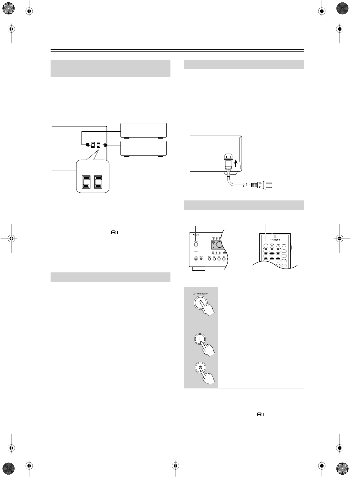
38
Connecting the AV receiver
—Continued
The AV receiver has AC outlets on its rear panel that can
be used to connect the power cords of AV other compo-
nents that you intend to use with the AV receiver. These
components can then be left turned on so that they turn
on and off as and when the AV receiver is turned on and
set to Standby.
Caution:
• Make sure that the total capacity of the components
that you connect to the AC OUTLETS does not exceed
the stated capacity (e.g., TOTAL 120 W).
Note:
• Integra components with jacks should be con-
nected directly to wall outlets, not the AV receiver’s
AC OUTLETS.
• The number of AC OUTLETS, socket type, and total
capacity depends on the country in which you pur-
chased the AV receiver.
This port can be used to connect an external controller
for controlling the AV receiver.
Plug the supplied power cord into this AC INLET.
• Do not use a power cord other than the one supplied
with this AV receiver. It’s designed exclusively for use
with this AV receiver and should not be used with any
other component.
•Never disconnect the power cord from the AV receiver
while the other end is still plugged into a wall outlet.
Doing so may cause an electric shock. Always discon-
nect the power cord from the wall outlet first.
Notes:
•Pressing the remote controller’s [On] button once will
turn on the AV receiver. Pressing it again will turn on
any components connected via .
• When the AV receiver is on Standby, it will turn on
automatically when any one of its input selector but-
tons is pressed.
Connecting the Power Cords of Other
Components
Connecting the RS232 Port
AC OUTLETS
AC
120
V 60
Hz
SWITCHED
TOTAL 120W 1A MAX.
Connecting the Supplied Power Cord
Turning On the AV receiver
Press the [Standby/On] button.
Alternatively, press the remote
controller’s [Receiver] button fol-
lowed by the [On] button.
The AV receiver comes on, the display
lights up, and the Standby indicator
goes off.
To turn off the AV receiver, press the
[Standby/On] button. The AV receiver
will enter Standby mode.
AC
INLET
DO NOT connect the
power cord at this time.
Power cord
(supplied)
Standby
Zone 2
On Standby TV
TV CH
TV VOL
--
/
---
Input
I
+10 0 Clear
123
456
789
+
-
V1V2V3
CD
Phono
Tape
V4DVD
Multi CH
Tuner
Standby/On Standby
On
Standby
On
Remote
controller
DTR-6.5,5.5_En.book Page 38 Wednesday, July 28, 2004 9:07 AM
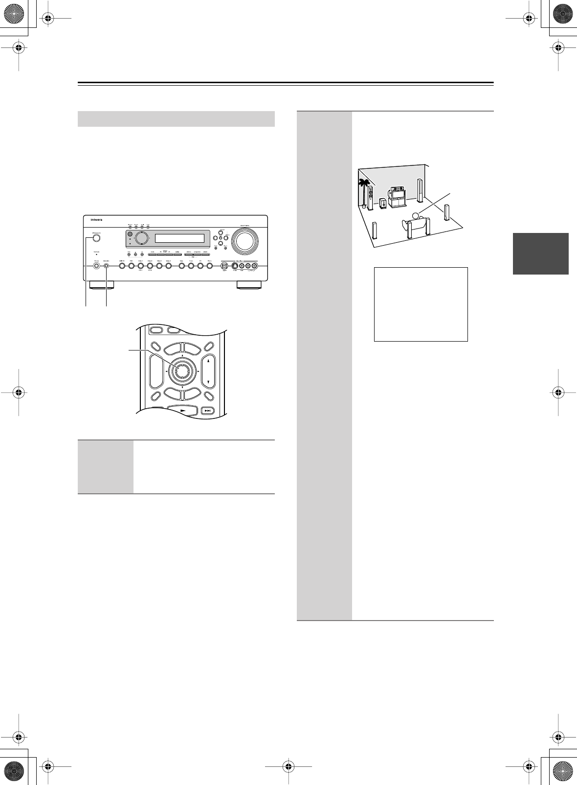
39
First Time Setup
This chapter explains the settings that you need to make before using the AV receiver.
With the supplied speaker setup microphone, the Auto-
matic Speaker Setup function can measure the test tone
output by each speaker and automatically determine the
number of speakers connected, their sizes, the distance
from each speaker to the listening position, and so on.
Before using this function, connect and position all your
speakers.
Automatic Speaker Setup
1
Turn on the AV receiver and the
connected TV.
On the TV, select the input to which the
AV receiver is connected.
On Standby TV
Display Muting
E
x
i
t
G
u
i
d
e
Prev
CH
TV CH
TV VOL
--
/
---
Dimmer
Tape
TV
Input
Sleep
Input
I
Enter
T
o
p
M
e
n
u
M
e
n
u
S
e
t
u
p
R
e
t
u
r
n
VOL
CH
Disc
SATTV VCR Cable
DVD
Receiver
CD
+10 0 Clear
123
456
789
+
-
Macro
123
MD/CDR
+
-
Input Selector
V1V2V3
CD
Phono
Tape
V4DVD
Multi CH
Tuner
Remote Mode
Zone 2
3–7
Standby
Zone 2
21
2
Put the speaker setup micro-
phone in the listening position,
and connect it to the Setup Mic
jack.
Notes:
•Wait at least five seconds after turn-
ing on the AV receiver before plug-
ging in the speaker setup
microphone.
• Make sure the microphone is hori-
zontal.
• If there’s an obstacle between the
microphone and any speaker, the
automatic setup will not work cor-
rectly. Set the room how you would
have it when enjoying a DVD.
• If the AV receiver was previously
muted, the Muting function will be
cancelled.
• The automatic setup cannot be used
while a pair of headphones is con-
nected.
• By putting the microphone close to
where your ears would normally be
at the listening position, a more accu-
rate setup can be achieved. If you use
a tripod or level table, you can adjust
the height of the microphone.
MIC
position
Auto Speaker Setup
------------------------
Push Enter:Start
DTR-6.5,5.5_En.book Page 39 Wednesday, July 28, 2004 9:07 AM
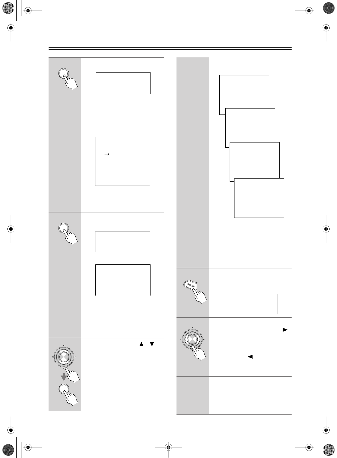
40
First Time Setup
—Continued
3
Press [Enter].
The automatic speaker setup starts.
The test tone, which is somewhat loud,
is output by each speaker in turn, mea-
sured by the microphone, and the
speaker settings set accordingly. The
whole process takes about 90 seconds.
If any extraneous noise is picked up by
the microphone, the automatic setup
will not work correctly, so be careful.
4
When the Check Result menu
appears, press [Enter].
The Setup Result menu appears.
5
Use the Up and Down [ ]/[ ]
buttons to select the item that
you want to check, and then
press [Enter].
Enter
Auto Speaker Setup
------------------------
Do not Unplug Setup Mic
Wait a moment, Please.
Auto Speaker Setup
------------------------
Do not Unplug Setup Mic
Left
Center
Right
Surr Right
SurrBack R
SurrBack L
Surr Left
Subwoofer
Enter
Auto Speaker Setup
------------------------
Push Enter:Check Results
<:Retry >:Set
1Warning
2Number of speakers and their sizes
3Distance from each speaker to the
listening position
4The optimum volume level for each
speaker
0.Auto Sp Setup Result
------------------------
1.Warning
2.Speaker Config
3.Distance
4.Level
Enter
Enter
Press the [Return] button to return to
the previous menu.
(Menus vary depending on country.)
*
When a speaker has a warning, its abbre-
viation (e.g., L, R, and so on) appears
instead of the “---” dashes.
If you want to adjust any of the settings
manually, see “Speaker Setup” on
page 46.
6
When you’ve checked the set-
tings, press the [Return] button
to return to the previous menu.
7
When you’ve finished the auto-
matic setup, press the Right [ ]
button.
That completes the setup.
To run the automatic setup again,
press the Left [ ] button.
The automatic speaker setup starts
again.
8
Disconnect the speaker setup
microphone.
To cancel the automatic setup while it’s
in progress, disconnect the micro-
phone.
0-1.Warning
------------------------
-:-:-:--:--:--:--:--
Not Connect
Too Near/Far Speaker
-:-:-:--:--:--:--:--
0-2.Speaker Config
------------------------
Front :Large
Center :Small
Surround :Small
SurroundBack :Small
SurrBack ch :2ch
Crossover :100Hz
Subwoofer :Yes
0-3.Distance
------------------------
Left : 3.6m
Center : 3.6m
Right : 3.6m
Surr Right : 2.1m
Surr Back R : 2.1m
Surr Back L : 2.1m
Surr Left : 2.1m
Subwoofer : 3.6m
0-4.Level
------------------------
Left : 0dB
Center : 0dB
Right : 0dB
Surr Right : 0dB
Surr Back R : 0dB
Surr Back L : 0dB
Surr Left : 0dB
Subwoofer : 0dB
*
Auto Speaker Setup
------------------------
Push Enter:Check Results
<:Retry >:Set
Enter
DTR-6.5,5.5_En.book Page 40 Wednesday, July 28, 2004 9:07 AM
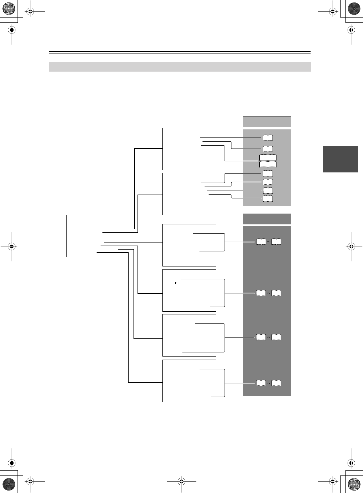
41
First Time Setup
—Continued
The AV receiver is configured using onscreen setup menus, which are displayed on the TV that’s connected to either of
the MONITOR OUT jacks. Because they appear on your TV, they’re large and clear, making setup a breeze.
Settings are divided into two groups:
Basic Setup
and
Advanced Setup
.
When you’ve configured the settings on the Basic Setup menu correctly, you’ll be ready to enjoy movies and music. The
Advanced Setup menu contains more detailed settings for an even better sound and increased enjoyment.
About the Onscreen Setup Menus
Menu
------------------------
1.Initial Setup
2.Speaker Setup
Advanced Setup
3.Decorder Setup
4.Audio Adjust
5.Listening Mode Preset
6.Preference
Basic Setup
1.Initial Setup
------------------------
2.Component Video
3.Hardware Setup
1.Digital Input
2.Speaker Setup
------------------------
2.Speaker Distance
3.Level Calibration
4.Equalizer Settings
1.Speaker Config
3.Decoder Setup
------------------------
2.Dolby Digital
3.DTS
4.D.F.2ch
5.Multiplex
6.Multich Input
1.Analog/PCM
4.Audio Adjust
------------------------
2.PL x/Neo:6
3.Enhance
4.Orchestra
5.Unplugged
6.Studio-Mix
7.TV Logic
8.Mono Movie
9.Theater-Dimensional
1.Mono
5.Listening Mode Preset
------------------------
2.VIDEO1
3.VIDEO2
4.VIDEO3
5.VIDEO4
6.TAPE
7.TUNER
8.CD
9.PHONO
1.DVD/MULTICH
6.Preference
------------------------
2.Volume Setup
3.OSD Setup
4.Remote Setup
5.Digital Format
6.12V Trigger A Setup
7.12V Trigger B Setup
8.12V Trigger C Setup
1.IntelliVolume
Main menus
Submenus
p. 42
p. 46
p. 66
p. 68
p. 70
p. 72
p. 43
p. 44, 45
p. 48
p. 50
p. 51
p. 70
p. 73
Basic Setup
Advanced Setup
p. 67
p. 71
p. 75, 76
DTR-6.5,5.5_En.book Page 41 Wednesday, July 28, 2004 9:07 AM
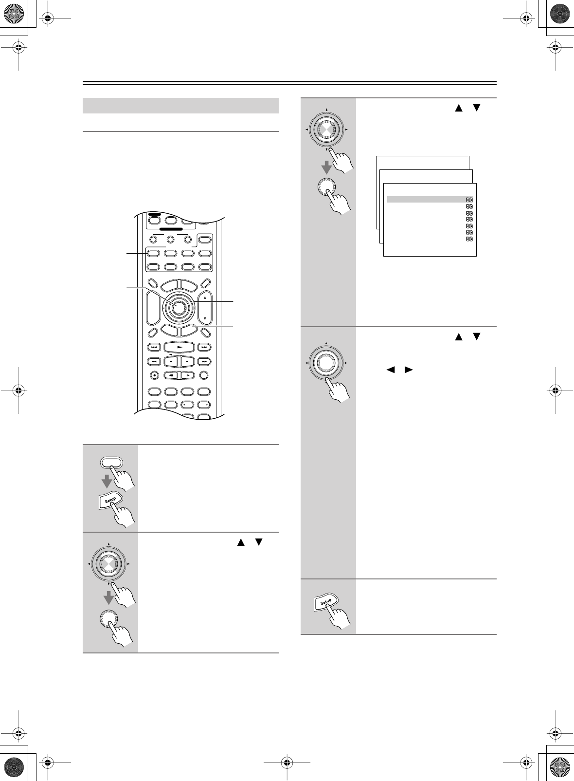
42
First Time Setup
—Continued
Digital Input
If you connect a component to a digital input jack, you
must assign that jack to an input selector. For example, if
you connect your CD player to the OPTICAL IN2 jack,
you should assign that jack to the CD input selector. By
default, the OPTICAL IN1 jack is assigned to the DVD
input selector, although this can be changed.
Note:
• This procedure can also be performed on the AV
receiver by using its [Setup] button, arrow buttons, and
[Enter] button.
Initial Setup
1
Press the [Receiver] button fol-
lowed by the [Setup] button.
The main menu appears onscreen.
2
Use the Up and Down [ ]/[ ]
buttons to select “1. Initial
Setup,” and then press [Enter].
The Initial Setup menu appears.
Pure A
Display Muting
RandomRec
Last Memory
AngleSubtitleAudio
MemorySearchA-BRepeat
E
x
i
t
G
u
i
d
e
Prev
CH
TV VOL
--
/
---
Dimmer
Tape
TV
Input
Sleep
Enter
Test Tone
CH SEL
Surround
THX
Direct
StereoAll ST
Level+
Level-
DSP DSP
T
o
p
M
e
n
u
M
e
n
u
S
e
t
u
p
R
e
t
u
r
n
VOL
CH
Disc
SATTV VCR Cable
DVD
Receiver
CD
+10 0 Clear
789
Video OffOpen/Close
Macro
123
MD/CDR
+
-
Input Selector
CD
Phono
Tape
Tuner
Remote Mode
Zone 2
2–4
2, 3
1, 5
1
Receiver
Enter
Enter
3
Use the Up and Down [ ]/[ ]
buttons to select “1. Digital
Input,” and then press [Enter].
The Digital Input menu appears.
• There are no assignments for
TUNER.
• VIDEO 4 is assigned to the optical
digital input on the front panel and
cannot be changed.
4
Use the Up and Down [ ]/[ ]
buttons to select an input selec-
tor, and then use the Left and
Right [ ]/[ ] buttons to select a
digital input jack.
Examples:
If you connect your DVD player to the
OPTICAL IN 2 jack, set “a. DVD” to
“OPT2.”
If you want to listen to audio from the
component connected to the OPTICAL
IN 3 jack when the VIDEO 1 input
selector is selected, set “b. VIDEO1” to
“OPT3.”
If you want to listen to audio from the
component connected to the COAX-
IAL IN 1 jack when the VIDEO 2 input
selector is selected, set “c. VIDEO2” to
“COAX1.”
For input selectors that you don’t want
to assign a digital input jack, leave them
set to “-----.”
5
Press the [Setup] button.
The setup menu closes.
Enter
Enter
Menu
------------------------
1.Initial Setup
2.Speaker Setup
Advanced Setup
3.Surround Setup
4.Audio Adjust
5.Listening Mode Preset
6.Preference
Basic Setup
1.Initial Setup
------------------------
2.Component Video
3.Hardware Setup
1.Digital Input
1-1.Digital Input
a.DVD :OPT1
------------------------
b.VIDEO1 :-----
c.VIDEO2 :-----
d.VIDEO3 :-----
e.TAPE :-----
f.CD :-----
g.PHONO :-----
Enter
DTR-6.5,5.5_En.book Page 42 Wednesday, July 28, 2004 9:07 AM
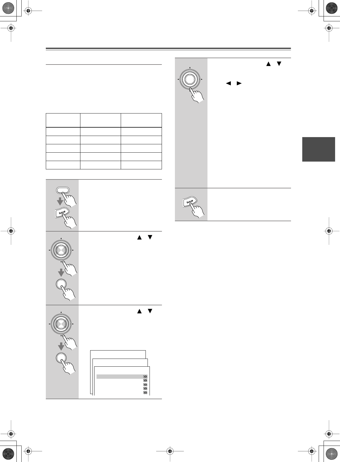
43
First Time Setup
—Continued
Component Video Setup
If you connect to a COMPONENT VIDEO IN, you must
assign it to an input selector. For example, if you connect
your DVD player to COMPONENT IN 3, you should
assign it to the DVD input selector.
If you want to output composite and S-Video sources
from the COMPONENT VIDEO OUT, select Video, as
explained below.
Notes:
• If you select Last, the video source remains the same
when you select another input selector. For example,
if you set VIDEO 1 to Last, select the DVD input
selector, then select the VIDEO 1 input selector, you
can watch a DVD while listening to audio from the
component connected to the VIDEO 1 IN L/R jacks.
• This procedure can also be performed on the AV
receiver by using its [Setup] button, arrow buttons, and
[Enter] button.
Input
selector
Analog audio
input (fixed)
COMPONENT
VIDEO IN jack
DVD DVD IN 1
VIDEO 1 VIDEO 1 Video
VIDEO 2 VIDEO 2 Video
VIDEO 3 VIDEO 3 Video
VIDEO 4 VIDEO 4 Video
1
Press the [Receiver] button fol-
lowed by the [Setup] button.
The main menu appears onscreen.
2
Use the Up and Down [ ]/[ ]
buttons to select “1. Initial
Setup,” and then press [Enter].
The initial Setup menu appears.
3
Use the Up and Down [ ]/[ ]
buttons to select “2. Component
Video,” and then press the
[Enter] button.
The Component Video Setup menu
appears.
Receiver
Enter
Enter
Enter
Enter
Menu
------------------------
1.Initial Setup
2.Speaker Setup
Advanced Setup
3.Surround Setup
4.Audio Adjust
5.Listening Mode Preset
6.Preference
Basic Setup
1.Initial Setup
------------------------
2.Component Video
3.Hardware Setup
1.Digital Input
1-2.Component Video
------------------------
b.VIDEO1 :Video
c.VIDEO2 :Video
d.VIDEO3 :Video
e.VIDEO4 :Video
a.DVD/MULTICH :IN1
4
Use the Up and Down [ ]/[ ]
buttons to select an input selec-
tor, and then use the Left and
Right [ ]/[ ] buttons to select:
IN1:
Use the video component
connected to COMPO-
NENT VIDEO IN 1.
IN2:
Use the video component
connected to COMPO-
NENT VIDEO IN 2.
IN3:
Use the video component
connected to COMPO-
NENT VIDEO IN 3.
Video:
Output composite video
and S-Video sources from
the COMPONENT
VIDEO OUT.
Last:
Select this for audio-only
components.
5
Press the [Setup] button.
The setup menu closes.
Enter
DTR-6.5,5.5_En.book Page 43 Wednesday, July 28, 2004 9:07 AM
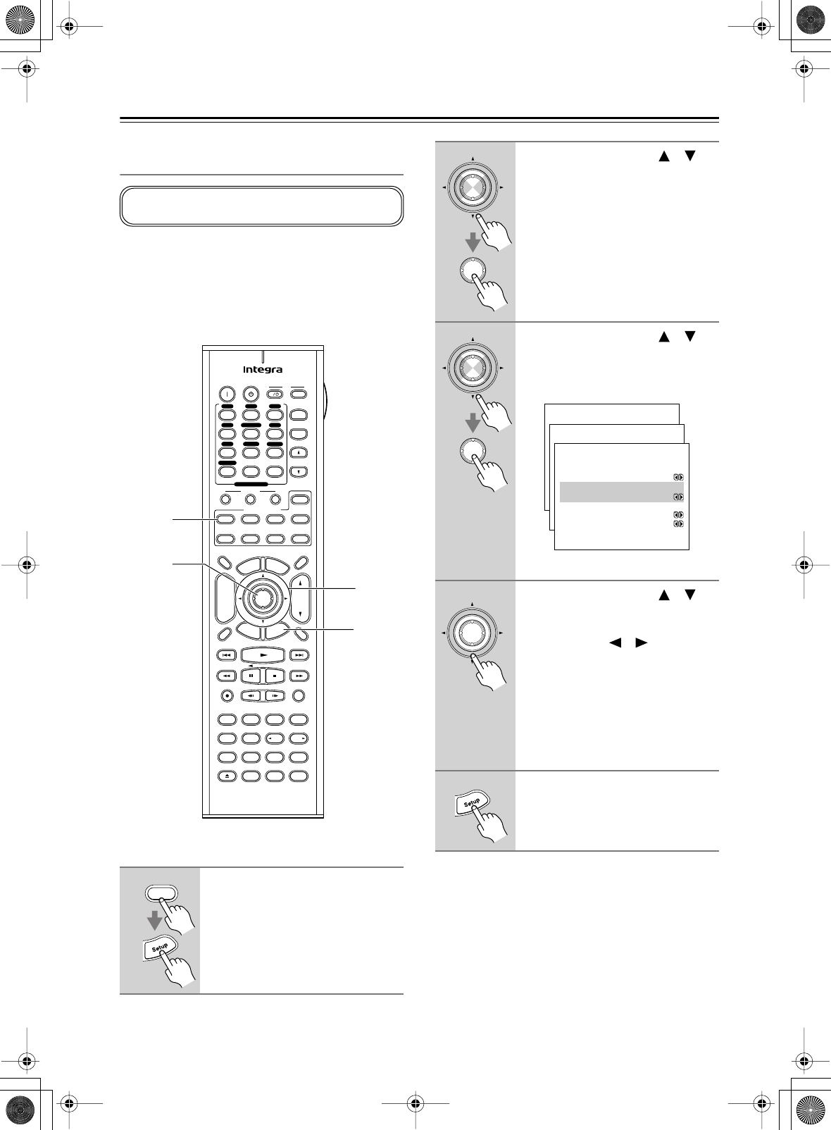
44
First Time Setup
—Continued
Minimum Speaker Impedance
(not American models)
If the impedance of any of the connected speakers is 4
ohms or more, but less than 6 ohms, set the Minimum
Speaker Impedance to “4 ohms.”
Note:
Before you change this setting, turn down the volume.
Notes:
• This procedure can also be performed on the AV
receiver by using its [Setup] button, arrow buttons, and
[Enter] button.
1
Press the [Receiver] button fol-
lowed by the [Setup] button.
The main menu appears onscreen.
This setting is not set automatically by the Automatic
Speaker Setup function (see page 39).
Pure A
On Standby TV
Display Muting
RandomRec
Last Memory
AngleSubtitleAudio
MemorySearchA-BRepeat
RC-585M
E
x
i
t
G
u
i
d
e
Prev
CH
TV CH
TV VOL
--
/
---
Dimmer
Tape
TV
Input
Sleep
Input
I
Enter
Test Tone
CH SEL
Surround
THX
Direct
StereoAll ST
Level+
Level-
L Night
DSP DSP
T
o
p
M
e
n
u
M
e
n
u
S
e
t
u
p
R
e
t
u
r
n
VOL
CH
Disc
SATTV VCR Cable
DVD
Receiver
CD
+10 0 Clear
123
456
789
+
-
Video OffOpen/Close
Macro
123
MD/CDR
Re-EQ
+
-
Input Selector
V1V2V3
CD
Phono
Tape
V4DVD
Multi CH
Tuner
Remote Mode
Zone 2
2–4
1, 5
2, 3
1
Receiver
2
Use the Up and Down [ ]/[ ]
buttons to select “1. Initial
Setup,” and then press [Enter].
The Initial Setup menu appears.
3
Use the Up and Down [ ]/[ ]
buttons to select “3. Hardware
Setup,” and then press [Enter].
The Hardware Setup menu appears.
(Menus vary depending on country.)
4
Use the Up and Down [ ]/[ ]
buttons to select “b. Sp Imped-
ance Minimum,” and then use the
Left and Right [ ]/[ ] buttons to
select:
4 ohms:
Select if the impedance of any
connected speaker is 4 ohms
or more, but less than 6 ohms.
6 ohms:
Select if the impedances of all
connected speakers are
between 6 and 16 ohms.
5
Press the [Setup] button.
The setup menu closes.
Enter
Enter
Enter
Enter
Menu
------------------------
1.Initial Setup
2.Speaker Setup
Advanced Setup
3.Surround Setup
4.Audio Adjust
5.Listening Mode Preset
6.Preference
Basic Setup
1.Initial Setup
------------------------
2.Component Video
3.Hardware Setup
1.Digital Input
1-3.Hardware Setup
------------------------
:Not Activated
b.Zone2 Out
:Fixed
c.Sp Impedance Minimum
:6ohms
d.TV Format :AUTO
a.Powered Zone2
Enter
DTR-6.5,5.5_En.book Page 44 Wednesday, July 28, 2004 9:07 AM
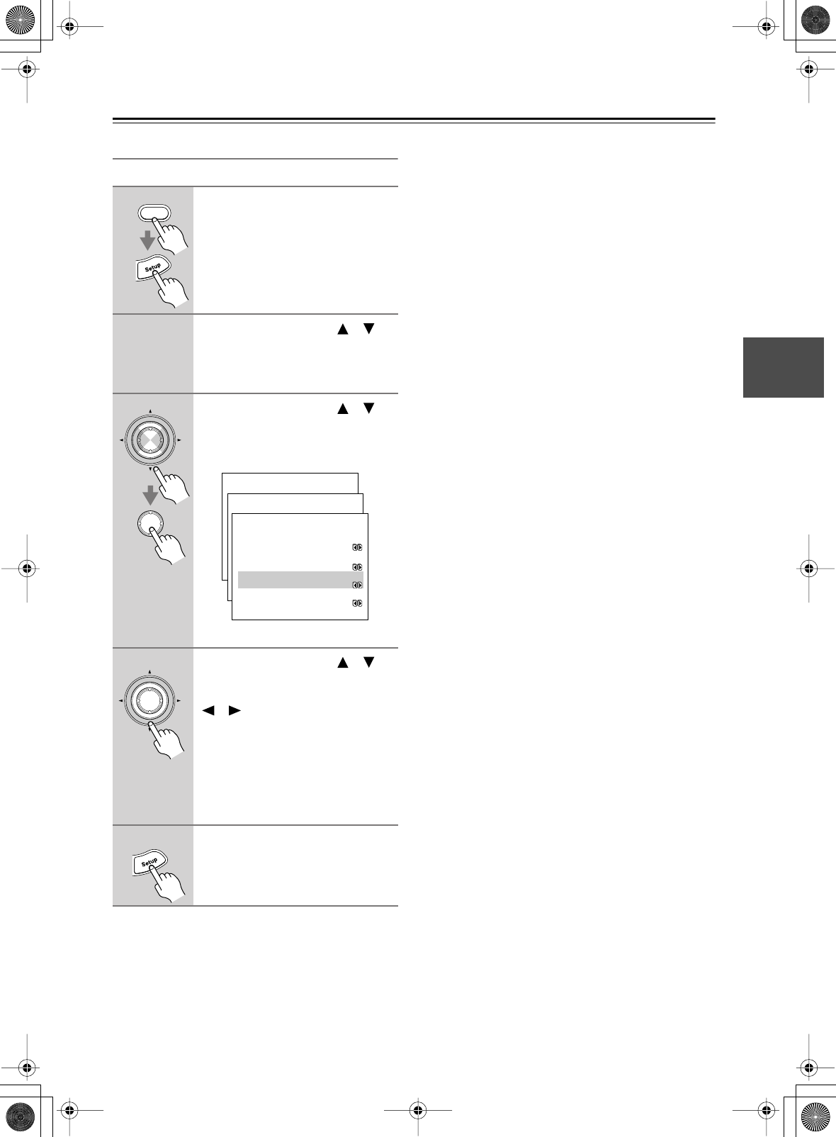
45
First Time Setup
—Continued
TV Format Setup (not American models)
Here you can specify the TV format used in your area.
Note:
• This procedure can also be performed on the AV
receiver by using its [Setup] button, arrow buttons, and
[Enter] button.
1
Press the [Receiver] button fol-
lowed by the [Setup] button.
The main menu appears onscreen.
2
Use the Up and Down [ ]/[ ]
buttons to select “1. Initial
Setup,” and then press [Enter].
The Initial Setup menu appears.
3
Use the Up and Down [ ]/[ ]
buttons to select “3. Hardware
Setup,” and then press [Enter].
The Hardware Setup menu appears.
(Menus vary depending on country.)
4
Use the Up and Down [ ]/[ ]
buttons to select “c. TV Format,”
and then use the Left and Right
[ ]/[ ] buttons to select:
Auto:
Conforms with the video
input signal.
PAL:
Select if the TV system in
your area is PAL.
NTSC:
Select if the TV system in
your area is NTSC.
5
Press the [Setup] button.
The setup menu closes.
Receiver
Enter
Enter
Menu
------------------------
1.Initial Setup
2.Speaker Setup
Advanced Setup
3.Surround Setup
4.Audio Adjust
5.Listening Mode Preset
6.Preference
Basic Setup
1.Initial Setup
------------------------
2.Component Video
3.Hardware Setup
1.Digital Input
1-3.Hardware Setup
------------------------
:Not Activated
b.Zone2 Out
:Fixed
c.Sp Impedance Minimum
:6ohms
d.TV Format :AUTO
a.Powered Zone2
Enter
DTR-6.5,5.5_En.book Page 45 Wednesday, July 28, 2004 9:07 AM
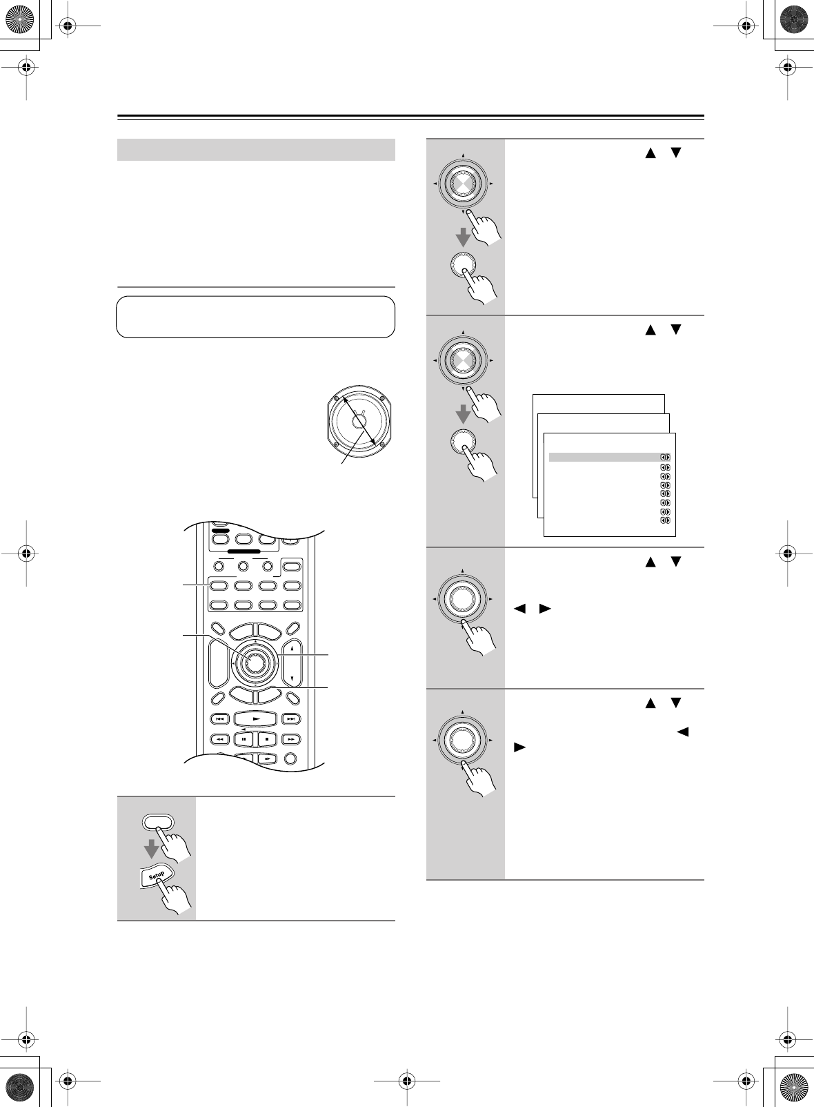
46
First Time Setup
—Continued
Some of the settings in this section are set automatically
by the Automatic Speaker Setup function (see page 39).
Here you can check the settings made by the Automatic
Speaker Setup function, or set them manually, which is
useful if you change one of the connected speakers after
using the Automatic Speaker Setup function.
Speaker Configuration
Here you can specify which speakers are connected and
their individual sizes.
For speakers with a cone diameter
over 6-1/2 inches (16 cm), specify
large,
and for those with a diameter
below this, specify
small.
For the DTR-6.5, if you’re using
THX-certified speakers, specify
Small
for all speakers.
Speaker Setup
1
Press the [Receiver] button fol-
lowed by the [Setup] button.
The main menu appears onscreen.
This setting is set automatically by the Automatic
Speaker Setup function (see page 39).
Cone diameter
Display Muting
RandomRec
Last Memory
AngleSubtitleAudio
E
x
i
t
G
u
i
d
e
Prev
CH
TV VOL
--
/
---
Dimmer
Tape
TV
Input
Sleep
Enter
Surround
THX StereoAll ST
T
o
p
M
e
n
u
M
e
n
u
S
e
t
u
p
R
e
t
u
r
n
VOL
CH
Disc
SATTV VCR Cable
DVD
Receiver
CD
+10 0 Clear
789
Macro
123
MD/CDR
+
-
Input Selector
CD
Phono
Tape
Tuner
Remote Mode
Zone 2
1, 12
2–11
2, 3
1
Receiver
2
Use the Up and Down [ ]/[ ]
buttons to select “2. Speaker
Setup,” and then press [Enter].
The Speaker Setup menu appears.
3
Use the Up and Down [ ]/[ ]
buttons to select “1. Speaker
Config,” and then press [Enter].
The Speaker Config menu appears.
4
Use the Up and Down [ ]/[ ]
buttons to select “a. Subwoofer,”
and then use the Left and Right
[ ]/[ ] buttons to select:
Yes:
Select if a subwoofer is con-
nected.
No:
Select if no subwoofer is con-
nected.
5
Use the Up and Down [ ]/[ ]
buttons to select “b. Front,” and
then use the Left and Right [ ]/
[] buttons to select:
Small:
Select if the front speakers are
small.
Large:
Select if the front speakers are
large.
Note:
• If the Subwoofer setting in step 4 is
set to No, this setting is fixed at
Large.
Enter
Enter
Enter
Enter
Menu
------------------------
1.Initial Setup
2.Speaker Setup
Advanced Setup
3.Surround Setup
4.Audio Adjust
5.Listening Mode Preset
6.Preference
Basic Setup
2.Speaker Setup
------------------------
2.Speaker Distance
3.Level Calibration
4.Equalizer Settings
1.Speaker Config
2-1.Speaker Config
------------------------
b.Front :Large
c.Center :Small
d.Surround :Small
e.SurroundBack :Small
f.SurrBack ch :2ch
g.Crossover :100Hz
h.Double Bass :Off
a.Subwoofer :Yes
Enter
Enter
DTR-6.5,5.5_En.book Page 46 Wednesday, July 28, 2004 9:07 AM
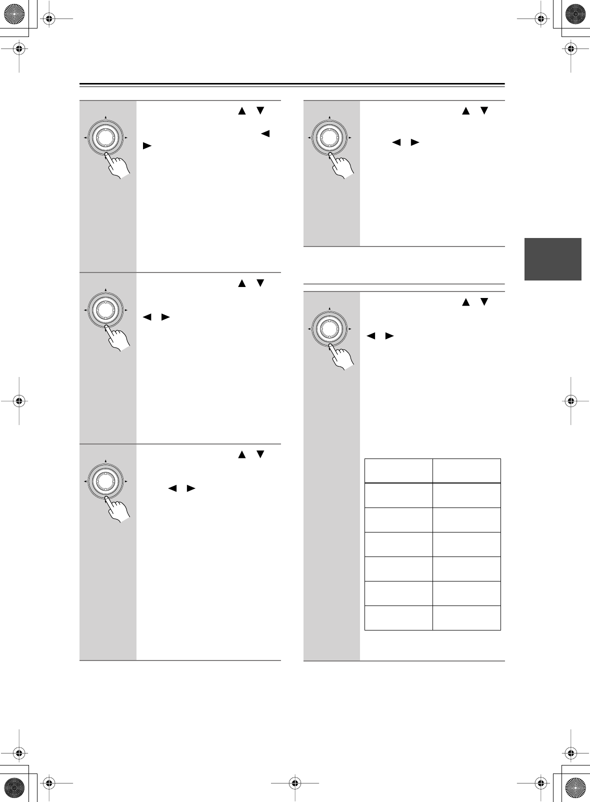
47
First Time Setup
—Continued
Crossover
Notes:
•If the crossover frequency is set to a low value, and the
program material doesn’t contain any sounds below
that frequency, the subwoofer will not output much
sound.
6
Use the Up and Down [ ]/[ ]
buttons to select “c. Center,” and
then use the Left and Right [ ]/
[] buttons to select:
Small:
Select if the center speaker is
small.
Large:
Select if the center speaker is
large.
None:
Select if no center speaker is
connected.
Note:
• If the Front setting in step 5 is set to
Small, the Large option cannot be
selected.
7
Use the Up and Down [ ]/[ ]
buttons to select “d. Surround,”
and then use the Left and Right
[ ]/[ ] buttons to select:
Small:
Select if the surround left and
right speakers are small.
Large:
Select if the surround left and
right speakers are large.
None:
Select if no surround left and
right speakers are connected.
Note:
• If the Front setting in step 5 is set to
Small, the Large option cannot be
selected.
8
Use the Up and Down [ ]/[ ]
buttons to select “e. Surround
Back,” and then use the Left and
Right [ ]/[ ] buttons to select:
Small:
Select if the surround back
left and right speakers are
small.
Large:
Select if the surround back
speakers are large.
None:
Select if no surround back
speakers are connected.
Notes:
•If the Surround setting in step 7 is set
to None, this setting cannot be
selected.
•If the Surround setting in step 7 is set
to Small, this setting cannot be set to
Large.
Enter
Enter
Enter
9
Use the Up and Down [ ]/[ ]
buttons to select “f. SurrBack
ch,” and then use the Left and
Right [ ]/[ ] buttons to select:
1ch:
Select if one surround back
speaker is connected.
2ch:
Select if two (left and right)
surround back speakers are
connected.
Continue with step 10 in the right col-
umn.
10
Use the Up and Down [ ]/[ ]
buttons to select “g. Crossover,”
and then use the Left and Right
[ ]/[ ] buttons to select a
crossover frequency.
Choose a crossover frequency suitable
for your setup. If you’re using a sub-
woofer, choose a crossover frequency
based on the diameter of your front
speakers. If you’re not using a sub-
woofer, use the diameter of any speaker
that you specified as Small.
For the DTR-6.5, if you’re using THX-
certified speakers, select 80Hz (THX).
*DTR-6.5 only.
Continue with step 11 on the next page.
Enter
Enter
Speaker cone
diameter
Crossover
frequency
Over 12 in.
(30 cm) 40Hz*
8 to 12 in.
(20–30 cm) 60Hz
6-1/2 to 8 in.
(16–20 cm) 80Hz (THX)
5-1/4 to 6-1/2 in.
(13–16 cm) 100Hz
3-1/2 to 5-1/4 in.
(9–13 cm) 120Hz
Under 3-1/2 in.
(9 cm) 150Hz
DTR-6.5,5.5_En.book Page 47 Wednesday, July 28, 2004 9:07 AM
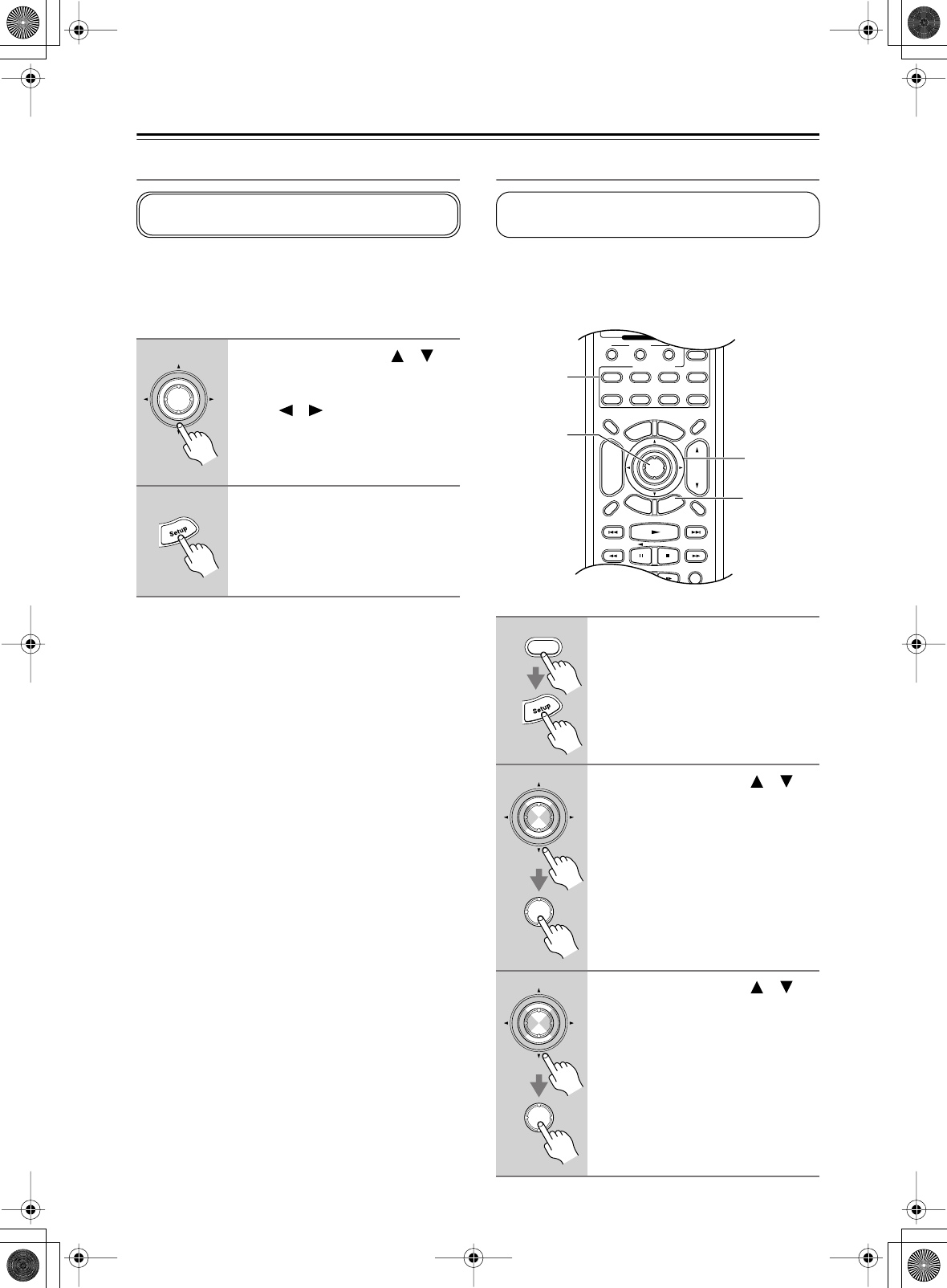
48
First Time Setup
—Continued
Double Bass
With the Double Bass function, you can boost bass out-
put by feeding bass sounds from the front left and right
channels to the subwoofer. This function can be set only
if the Subwoofer setting in step 4 is set to Yes, and the
Front setting in step 5 is set to Large.
Notes:
• This procedure can also be performed on the AV
receiver by using its [Setup] button, arrow buttons, and
[Enter] button.
Speaker Distance
Here you can specify the distance from each speaker to
the listening position so that the sound from each speaker
arrives at the listener’s ears as the sound designer
intended.
11
Use the Up and Down [ ]/[ ]
buttons to select “g. Double
Bass,” and then use the Left and
Right [ ]/[ ] buttons to select:
On:
Double Bass function on.
Off:
Double Bass function off
(default).
12
Press the [Setup] button.
The setup menu closes.
This setting is not set automatically by the Automatic
Speaker Setup function (see page 39).
Enter
1
Press the [Receiver] button fol-
lowed by the [Setup] button.
The main menu appears onscreen.
2
Use the Up and Down [ ]/[ ]
buttons to select “2. Speaker
Setup,” and then press [Enter].
The Speaker Setup menu appears.
3
Use the Up and Down [ ]/[ ]
buttons to select “2. Speaker Dis-
tance,” and then press [Enter].
This setting is set automatically by the Automatic
Speaker Setup function (see page 39).
Display Muting
RandomRec
E
x
i
t
G
u
i
d
e
Prev
CH
--
/
---
Dimmer
Tape
TV
Input
Sleep
Enter
T
o
p
M
e
n
u
M
e
n
u
S
e
t
u
p
R
e
t
u
r
n
VOL
CH
Disc
SATTV VCR Cable
DVD
Receiver
CD
+10 0 Clear
Macro
123
MD/CDR
+
-
Input Selector
Remote Mode
Zone 2
1, 7
2–5
2, 3
1
Receiver
Enter
Enter
Enter
Enter
DTR-6.5,5.5_En.book Page 48 Wednesday, July 28, 2004 9:07 AM
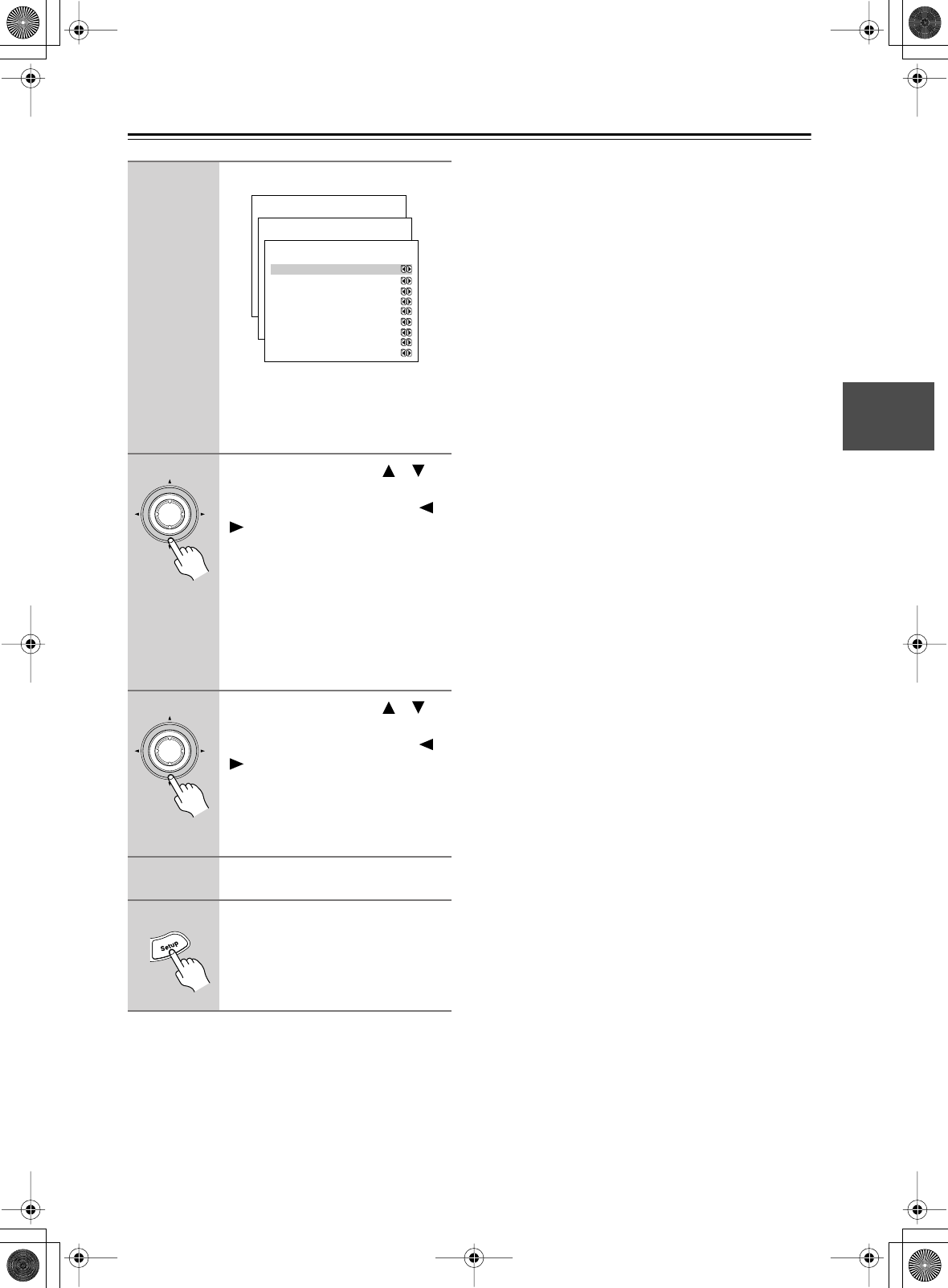
49
First Time Setup
—Continued
Notes:
• On the DTR-6.5, if the distance between the furthest
and nearest speakers is greater than 20 feet (6 meters),
corrected values suitable for home theater use will be
set automatically.
•On the DTR-5.5, the Center and Subwoofer distances
can be set up to 5 ft. (1.5 m) more or less than the
Front distance. For example, if the Front distance is set
to 20 ft. (6 m), the Center and Subwoofer distances
can be set between 15 and 25 ft. (4.5 and 7.5 m). The
SurrRight, Surr Left, and Surr Back distances can be
set up to 5 ft. (1.5 m) more or 15 ft. (4.5 m) less than
the Front distance. For example, if the Front distance
is set to 20 ft. (6 m), the SurrRight, Surr Left, and Surr
Back distances can be set between 5 and 25 ft. (1.5 and
7.5 m).
• This procedure can also be performed on the AV
receiver by using its [Setup] button, arrow buttons, and
[Enter] button.
The Speaker Distance menu appears.
Note:
Speakers that you set to No or None on
the Speaker Configuration page
(page 46) cannot be selected.
4
Use the Up and Down [ ]/[ ]
buttons to select “a. Unit,” and
then use the Left and Right [ ]/
[] buttons to select:
feet:
Select if you want to enter
distances in feet. Can be set
from 1 to 30 feet in 1-foot
steps.
meters:
Select if you want to enter
distances in meters. Can be
set from 0.3 to 9 meters in
0.3-meter steps.
5
Use the Up and Down [ ]/[ ]
buttons to select “b. Left,” and
then use the Left and Right [ ]/
[] buttons to specify the dis-
tance.
Specify the distance from the front left
speaker to your listening position.
6
Repeat step 5 for all speakers.
7
Press the [Setup] button.
The setup menu closes.
Menu
------------------------
1.Initial Setup
2.Speaker Setup
Advanced Setup
3.Surround Setup
4.Audio Adjust
5.Listening Mode Preset
6.Preference
Basic Setup
2.Speaker Setup
------------------------
2.Speaker Distance
3.Level Calibration
4.Equalizer Settings
1.Speaker Config
2-2.Speaker Distance
------------------------
b.Left : 3.6m
c.Center : 3.6m
d.Right : 3.6m
e.Surr Right : 2.1m
f.Surr Back R : 2.1m
g.Surr Back L : 2.1m
h.Surr Left : 2.1m
i.Subwoofer : 3.6m
a.Unit :meters
Enter
Enter
DTR-6.5,5.5_En.book Page 49 Wednesday, July 28, 2004 9:07 AM
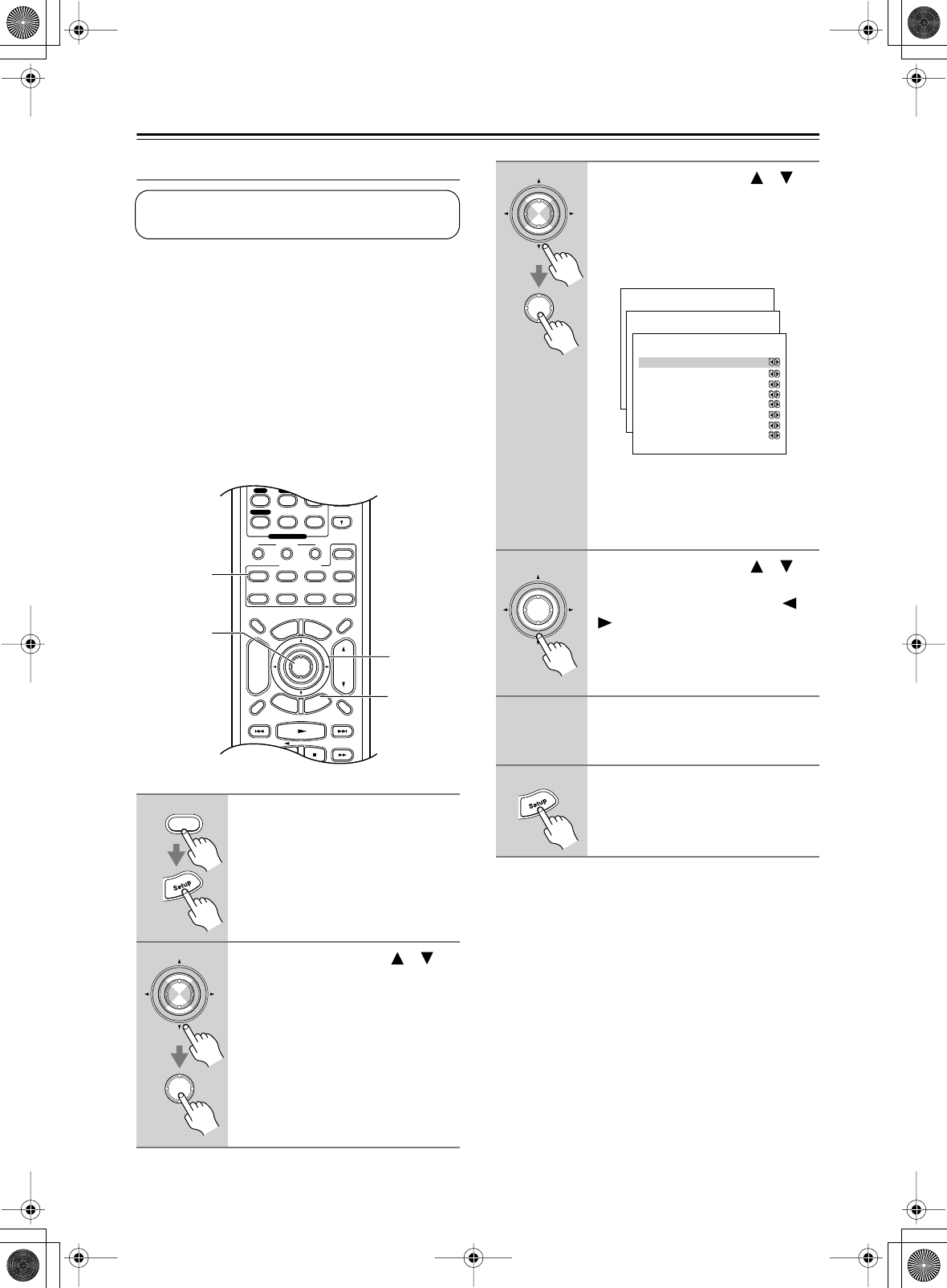
50
First Time Setup
—Continued
Speaker Level Calibration
Here you can adjust the level of each speaker with the
built-in test tone so that the volume of each speaker is the
same at the listening position.
Notes:
•The speakers cannot be calibrated while the output of
the AV receiver is muted, while a pair of headphones
is connected, or when using the multichannel input.
•Because the DTR-6.5 supports THX, the test tone is
output at the standard level of 0 dB (absolute vol-
ume setting 82). If you normally listen at volume
settings below this, be careful because the test tone
will be much louder.
Notes:
• This procedure can also be performed by using the
remote controller. First press the [Test Tone] button to
output the test tone. Use the [Level–] and [Level+]
buttons to set the volume, and use the [CH SEL] but-
ton to select the speakers.
1
Press the [Receiver] button fol-
lowed by the [Setup] button.
The main menu appears onscreen.
2
Use the Up and Down [ ]/[ ]
buttons to select “2. Speaker
Setup,” and then press [Enter].
The Speaker Setup menu appears.
This setting is set automatically by the Automatic
Speaker Setup function (see page 39).
Display Muting
RandomRec
E
x
i
t
G
u
i
d
e
Prev
CH
TV VOL
--
/
---
Dimmer
Tape
TV
Input
Sleep
Enter
T
o
p
M
e
n
u
M
e
n
u
S
e
t
u
p
R
e
t
u
r
n
VOL
CH
Disc
SATTV VCR Cable
DVD
Receiver
CD
+10 0 Clear
789
Macro
123
MD/CDR
+
-
Input Selector
CD
Phono
Tape
Tuner
Remote Mode
Zone 2
1, 6
2–4
2, 3
1
Receiver
Enter
Enter
3
Use the Up and Down [ ]/[ ]
buttons to select “3. Level Cali-
bration,” and then press [Enter].
The Level Calibration menu appears
and the pink noise test tone is output by
the front left speaker.
Note:
Speakers that you set to No or None on
the Speaker Configuration page
(page 46) cannot be selected.
4
Use the Up and Down [ ]/[ ]
buttons to select each speaker,
and use the Left and Right [ ]/
[] buttons to set the volume.
The volume can be adjusted from –12
to +12 dB in 1 dB steps (–15 to +12 dB
for the subwoofer).
5
Repeat step 4 until the volume of
the test tone from each speaker
is the same.
6
Press the [Setup] button.
The setup menu closes.
Enter
Enter
Menu
------------------------
1.Initial Setup
2.Speaker Setup
Advanced Setup
3.Surround Setup
4.Audio Adjust
5.Listening Mode Preset
6.Preference
Basic Setup
2.Speaker Setup
------------------------
2.Speaker Distance
3.Level Calibration
4.Equalizer Settings
1.Speaker Config
2-4.Equalizer Settings
------------------------
Left
a. 80Hz : 0dB
b. 250Hz : 0dB
c. 800Hz : 0dB
d.2.5kHz : 0dB
e. 8kHz : 0dB
Use Settings :Manual
2-3.Level Calibration
------------------------
b.Center : 0dB
c.Rught : 0dB
d.Surr Right : 0dB
e.Surr Back R : 0dB
f.Surr Back L : 0dB
g.Surr Left : 0dB
h.Subwoofer : 0dB
a.Left : 0dB
Enter
DTR-6.5,5.5_En.book Page 50 Wednesday, July 28, 2004 9:07 AM
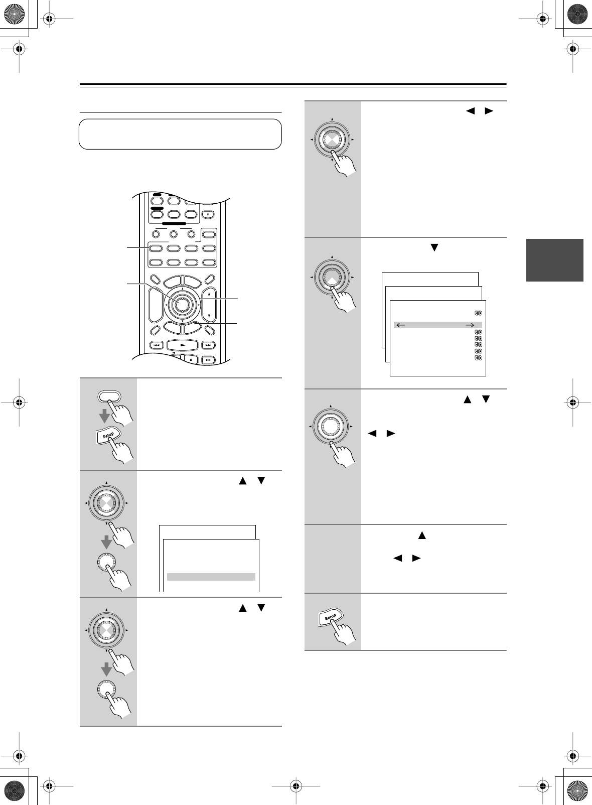
51
First Time Setup
—Continued
Equalizer Setting
Here you can adjust the EQ of individual speakers. The
volume of individual speakers can be set on page 50.
Notes:
• This procedure can also be performed on the AV
receiver by using its [Setup] button, arrow buttons, and
[Enter] button.
1
Press the [Receiver] button fol-
lowed by the [Setup] button.
The main menu appears onscreen.
2
Use the Up and Down [ ]/[ ]
buttons to select “2. Speaker
Setup,” and then press [Enter].
The Speaker Setup menu appears.
3
Use the Up and Down [ ]/[ ]
buttons to select “4. Equalizer
Settings,” and then press [Enter].
The Equalizer Settings menu appears.
This setting is set automatically by the Automatic
Speaker Setup function (see page 39).
Display Muting
RandomRec
E
x
i
t
G
u
i
d
e
Prev
CH
TV VOL
--
/
---
Dimmer
Tape
TV
Input
Sleep
Enter
T
o
p
M
e
n
u
M
e
n
u
S
e
t
u
p
R
e
t
u
r
n
VOL
CH
Disc
SATTV VCR Cable
DVD
Receiver
CD
+10 0 Clear
789
Macro
123
MD/CDR
+
-
Input Selector
CD
Phono
Tape
Tuner
Remote Mode
Zone 2
1, 8
2–7
2, 3
1
Receiver
Enter
Enter
Menu
------------------------
1.Initial Setup
2.Speaker Setup
Advanced Setup
3.Surround Setup
4.Audio Adjust
5.Listening Mode Preset
6P f
Basic Setup
2.Speaker Setup
------------------------
2.Speaker Distance
3.Level Calibration
4.Equalizer Settings
1.Speaker Config
Enter
Enter
4
Use the Left and Right [ ]/[ ]
buttons to select:
Off:
Tone off, response flat.
Auto:
The tone for each speaker is
set automatically by the Auto-
matic Speaker Setup function.
Manual:
You can adjust the EQ of each
speaker manually.
If you select Manual, continue with this
procedure. If you select Off or Auto, go
to step 8.
5
Use the Down [ ] button to
select a speaker.
6
Use the Up and Down [ ]/[ ]
buttons to select a frequency,
and then use the Left and Right
[ ]/[ ] buttons to adjust the
level at that frequency.
The volume at each frequency can be
adjusted from –12 to +12 dB in 1 dB
steps.
Tip:
Low frequencies (e.g., 80Hz)
affect bass sounds; high frequencies
(e.g., 8kHz) affect treble sounds.
7
Use the Up [ ] button to select
“Left,” and then use the Left and
Right [ ]/[ ] buttons to select
another speaker.
Repeat steps 6 and 7 for each speaker.
8
Press the [Setup] button.
The setup menu closes.
Enter
Enter
Menu
------------------------
1.Initial Setup
2.Speaker Setup
Advanced Setup
3.Surround Setup
4.Audio Adjust
5.Listening Mode Preset
6.Preference
Basic Setup
2.Speaker Setup
------------------------
2.Speaker Distance
3.Level Calibration
4.Equalizer Settings
1.Speaker Config
2-4.Equalizer Settings
------------------------
Left
a. 80Hz : 0dB
b. 250Hz : 0dB
c. 800Hz : 0dB
d.2.5kHz : 0dB
e. 8kHz : 0dB
Use Settings :Manual
Enter
DTR-6.5,5.5_En.book Page 51 Wednesday, July 28, 2004 9:07 AM
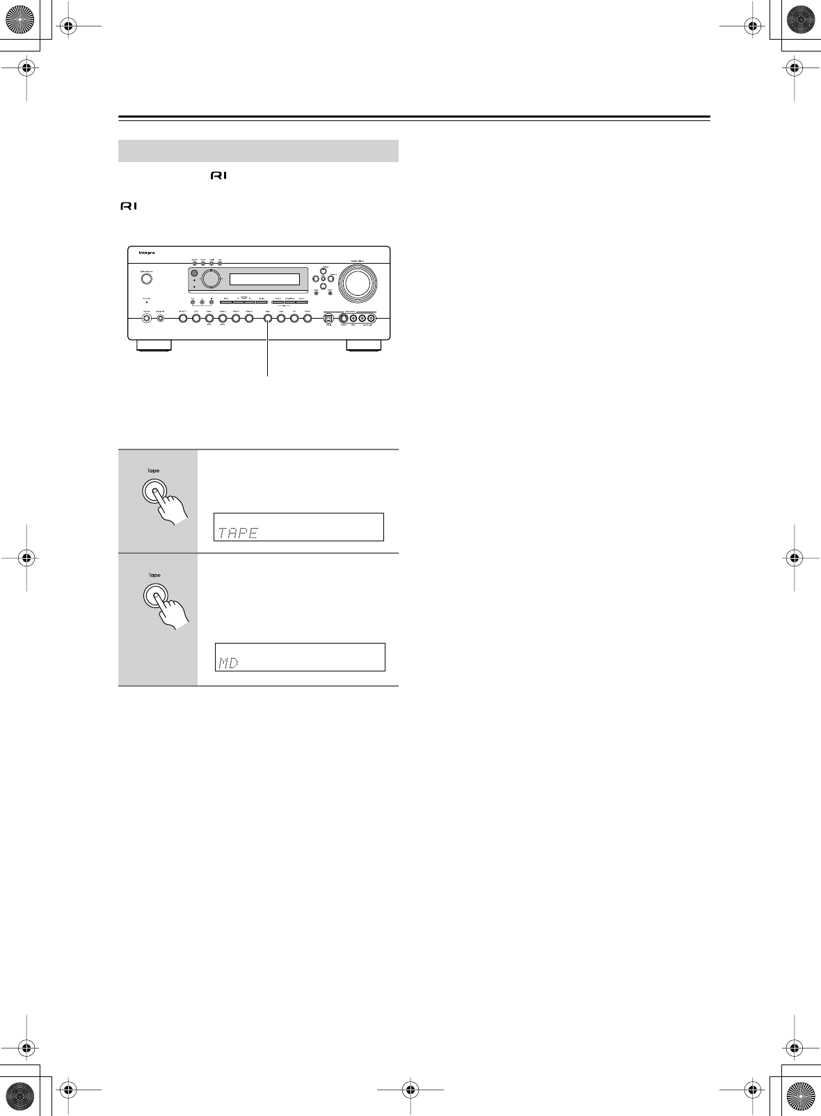
52
First Time Setup
—Continued
If you connect an -compatible Integra MiniDisc
recorder or CD recorder to the TAPE IN/OUT jacks, for
to work properly, you must change this setting.
This setting can only be changed on the AV receiver.
Changing the TAPE/MD/CDR Display
1
Press the [TAPE] input selector
button so that “TAPE” appears
on the display.
2
Press and hold down the [TAPE]
input selector button (about 3
seconds) to set the display.
Repeat this step to select TAPE, MD, or
CDR.
Standby
Zone 2
1, 2
(DTR-6.5 shown here)
DTR-6.5,5.5_En.book Page 52 Wednesday, July 28, 2004 9:07 AM
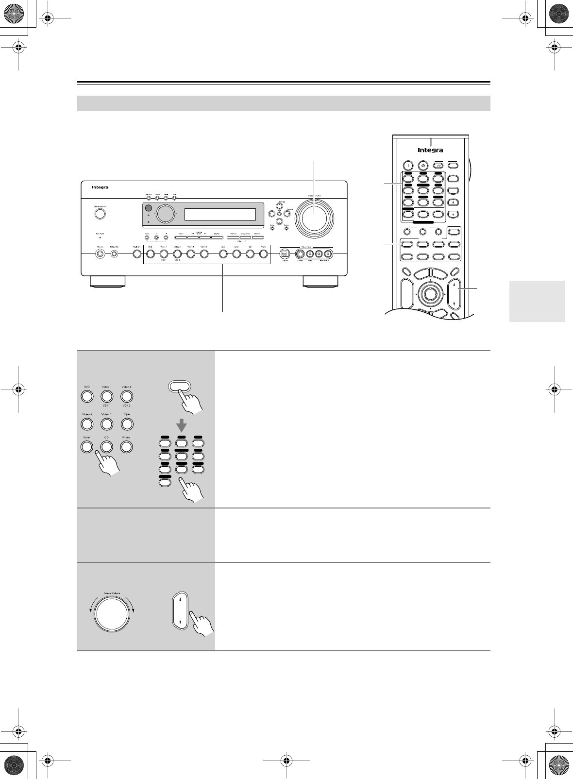
53
Basic Operation
This section explains how to select the input source (i.e., the AV component that you want to listen to or watch).
Selecting the Input Source
Standby
Zone 2
1
3
On Standby TV
Display Muting
E
x
i
t
G
u
i
d
e
Prev
CH
TV CH
TV VOL
--
/
---
Dimmer
Tape
TV
Input
Sleep
Input
I
Enter
T
o
p
M
e
n
u
M
e
n
u
S
e
t
u
p
R
e
t
u
r
n
VOL
CH
Disc
SATTV VCR Cable
DVD
Receiver
CD
+10 0 Clear
123
456
789
+
-
Macro
123
MD/CDR
+
-
Input Selector
V1V2V3
CD
Phono
Tape
V4DVD
Multi CH
Tuner
Remote Mode
Zone 2
3
1
1
1
Use the AV receiver’s input selector buttons to select the input
source.
To select the input source with the remote controller, press the
[Receiver] button, and then use the Input Selector buttons.
On the remote controller, the [V1], [V2], [V3], and [V4] buttons select the
VIDEO 1, VIDEO 2, VIDEO 3, and VIDEO 4 input sources respectively.
Only the RC-585M remote controller has a [PHONO] button.
2
Start playback on the source component.
When you select DVD or another video component, on your TV, you’ll need to
select the video input that’s connected to the AV receiver’s MONITOR OUT.
On some DVD players, you may need to turn on the digital audio output.
3
To adjust the volume, use the Master Volume control, or the remote
controller’s [VOL] button.
The volume can be set to MIN, 1 through 99, or MAX.
The AV receiver is designed for home theater enjoyment. It has a wide volume
range, allowing precise adjustment.
Receiver
V1V2V3
CD
Phono
Tap e
V4DVD
Multi CH
Tuner
or
Remote
controller
AV receiver
VOL
or
Remote
controller
AV receiver
DTR-6.5,5.5_En.book Page 53 Wednesday, July 28, 2004 9:07 AM
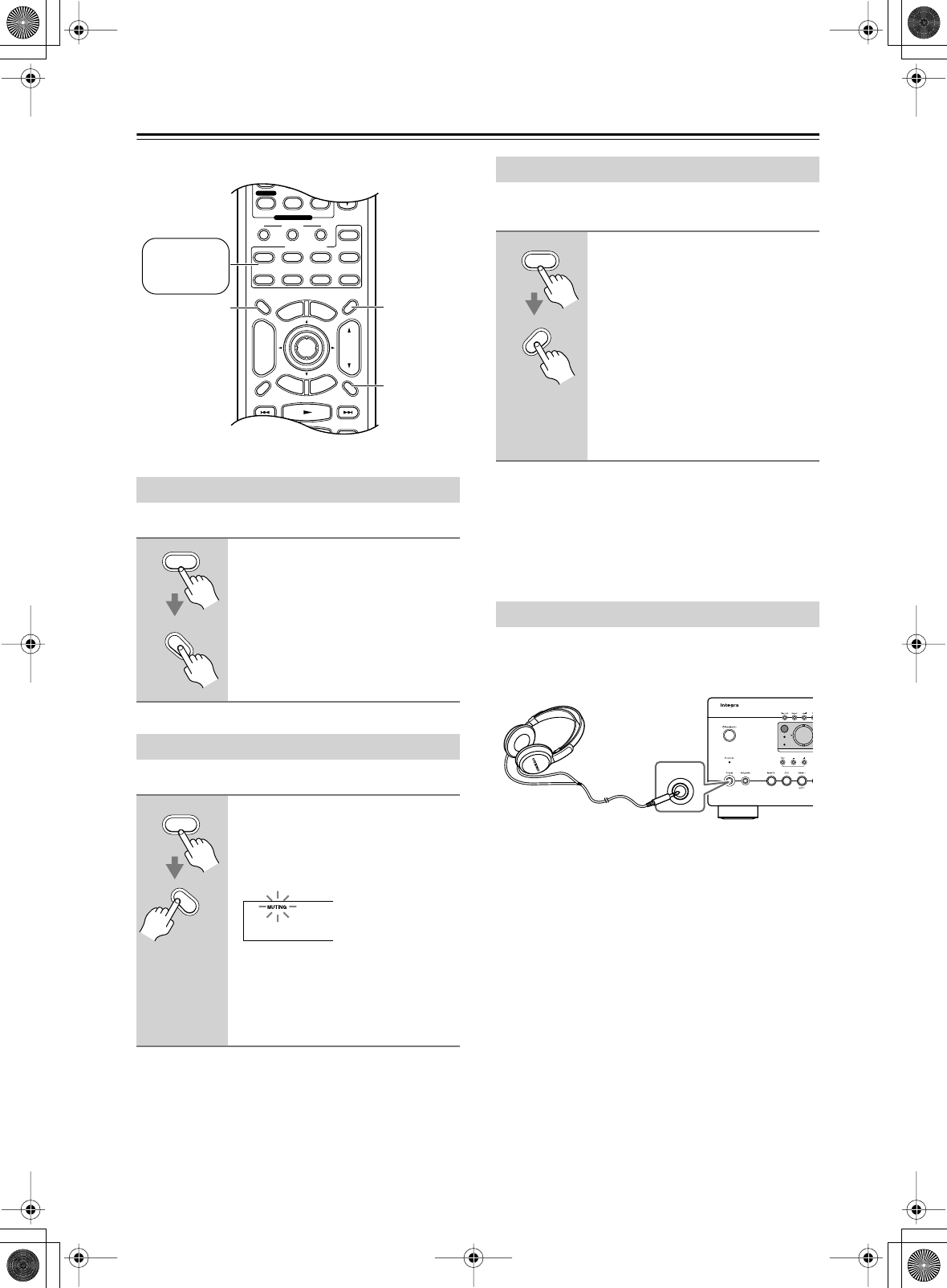
54
Basic Operation
—Continued
You can adjust the brightness of the display.
You can temporarily mute the output of the AV receiver.
With the sleep timer, you can set the AV receiver to auto-
matically turn off after a specified period.
If you need to cancel the sleep timer, press the [Sleep]
button repeatedly until the SLEEP indicator disappears.
To check the time remaining until the AV receiver sleeps,
press the [Sleep] button. Note that if you press the
[Sleep] button while the sleep time is being displayed,
you’ll shorten the sleep time by 10 minutes.
You can connect a pair of stereo headphones (1/4-inch
phone plug) to the AV receiver’s Phones jack for private
listening, as shown.
Notes:
•Always turn down the volume before connecting your
headphones.
•The speakers are turned off while the headphones plug
is inserted in the Phones jack. (Zone 2 speakers are not
turned off.)
•When you connect a pair of headphones, the listening
mode is set to Stereo, unless it’s already set to Stereo,
Mono, Direct, or Pure Audio. When you disconnect
the headphones, the previous listening mode is
resumed.
•Only the Stereo, Direct, Pure Audio, and Mono listen-
ing modes can be used with headphones. (The listen-
ing modes available also depends on the currently
selected input source.)
• When the multichannel input is used, only the front
left and right audio can be heard in the headphones.
On the DTR-6.5, when the Stereo or Mono listening
mode is selected, audio is downmixed for a good
sound.
Setting the Display Brightness
Press the [Receiver] button, and
then press the [Dimmer] button
repeatedly to select Normal, Dim
or Dimmer.
• Normal
• Dim
• Dimmer
Muting the AV receiver
Press the [Receiver] button, and
then press the [Muting] button.
The output is muted and the MUTING
indicator flashes on the display, as
shown.
To unmute the AV receiver, press the
[Muting] button again, or adjust the
volume.
The Mute function is cancelled when
the AV receiver is set to Standby.
Display Muting
RandomRec
E
x
i
t
G
u
i
d
e
Prev
CH
TV VOL
--
/
---
Dimmer
Tape
TV
Input
Sleep
Enter
T
o
p
M
e
n
u
M
e
n
u
S
e
t
u
p
R
e
t
u
r
n
VOL
CH
Disc
SATTV VCR Cable
DVD
Receiver
CD
+10 0 Clear
789
Macro
123
MD/CDR
+
-
Input Selector
CD
Phono
T
ape
T
uner
Remote Mode
Zone 2
Dimmer Sleep
Muting
Press
[Receiver]
first
Receiver
Dimmer
Receiver
Muting
Using the Sleep Timer
Press the [Receiver] button, and
then press the [Sleep] button
repeatedly to select the required
sleep time.
The sleep time can be set from 90 to 10
minutes in 10 minute steps.
The SLEEP indicator appears on the
display when the sleep timer has been
set, as shown. The specified sleep time
appears on the display for about five
seconds, then the previous display
reappears.
Using Headphones
Receiver
Sleep
Standby
Zone 2
Phones
DTR-6.5,5.5_En.book Page 54 Wednesday, July 28, 2004 9:07 AM
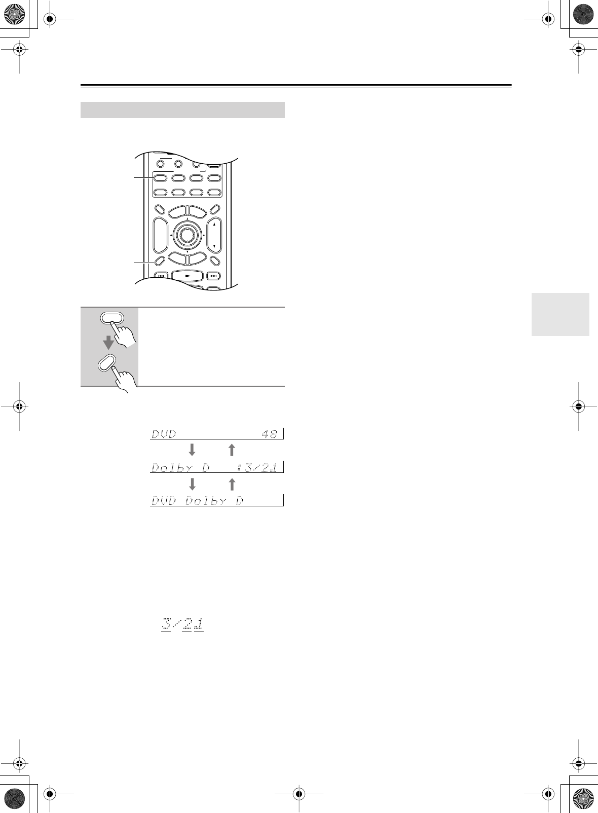
55
Basic Operation
—Continued
You can display various information about the current
input source as follows.
The following information can typically be displayed for
input sources.
*If the input signal is analog, no format information is
displayed. If the input signal is PCM, the sampling fre-
quency is displayed. If the input signal is digital but not
PCM, the signal format is displayed. Information is dis-
played for about three seconds, then the previously dis-
played information reappears.
Interpreting Surround Channel Values
A: The number of front channels (3 means front left,
front right, and center).
B: The number of surround channels (2 means surround
left and surround right). If there’s surround back
channel information, this will be 3.
C: LFE channel for subwoofer (1 means yes).
Displaying Source Information
Press the [Receiver] button, and
then press the [Display] button
repeatedly to cycle through the
available information.
Display Muting
RandomRec
E
x
i
t
G
u
i
d
e
Prev
CH
--
/
---
Dimmer
Tape
TV
Input
Sleep
Enter
T
o
p
M
e
n
u
M
e
n
u
S
e
t
u
p
R
e
t
u
r
n
VOL
CH
Disc
SATTV VCR Cable
DVD
Receiver
CD
+10 0 Clear
Macro
123
MD/CDR
+
-
Input Selector
Remote Mode
Zone 2
Receiver
Display
Receiver
Display
Input source &
volume
Signal format*
or sampling
frequency
Input source &
listening mode
ABC
DTR-6.5,5.5_En.book Page 55 Wednesday, July 28, 2004 9:07 AM
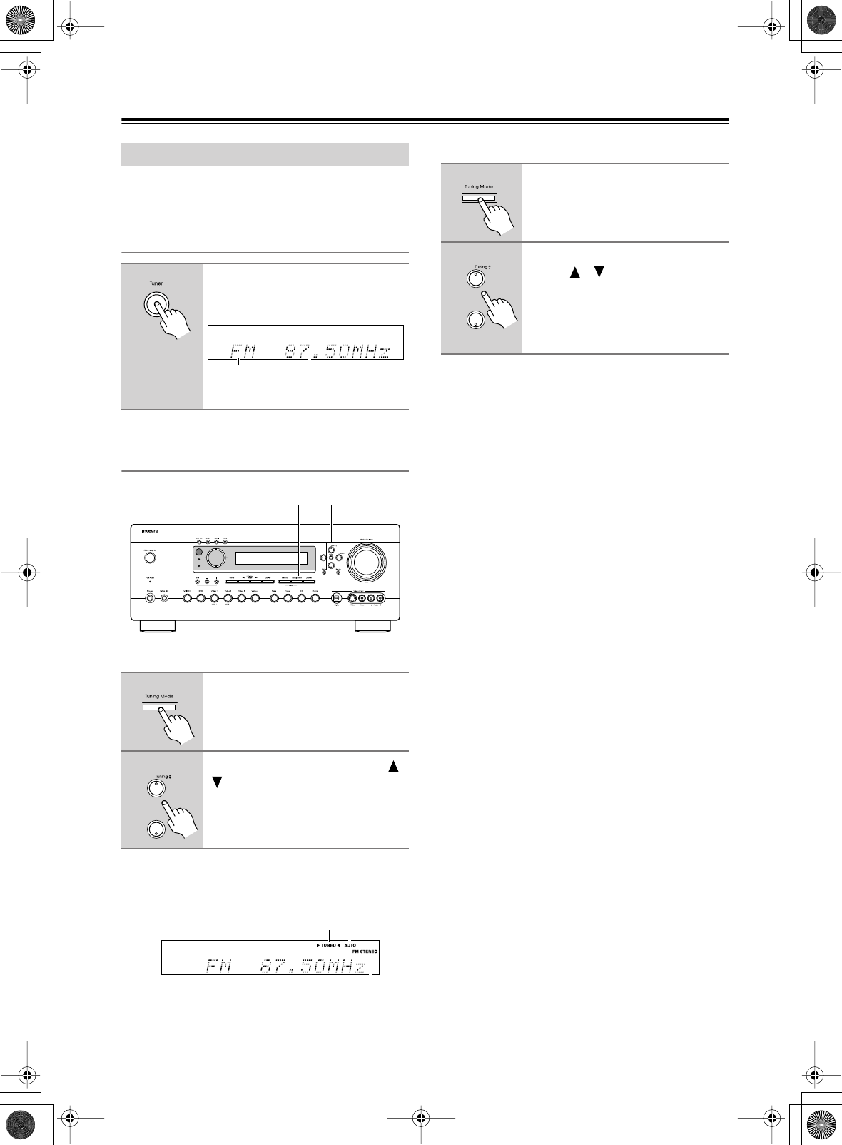
56
Basic Operation
—Continued
With the built-in tuner you can enjoy AM and FM radio
stations. You can store your favorite stations as presets
for quick selection.
Listening to the Radio
Tuning into Radio Stations
■
Auto Tuning Mode
When tuned into a station, the TUNED indicator
appears. When tuned into a stereo FM station, the FM
STEREO indicator appears on the display, as shown.
■
Manual Tuning Mode
The American model changes FM frequency in 0.2 MHz
steps, 10 kHz steps for AM. For other models it’s
0.05 MHz steps for FM and 9 kHz steps for AM.
In Manual Tuning mode, FM stations will be in mono.
Tuning into weak FM stereo stations
If the signal from a stereo FM station is weak, it may be
impossible to get good reception. In this case, switch to
Manual Tuning mode and listen to the station in mono.
Using the Tuner
1
Use the [TUNER] input selector
button to select either AM or FM.
In this example, FM has been selected.
(Actual display depends on country.)
1
Press the [Tuning Mode] button
so that the AUTO indicator
appears on the display.
2
Press the Tuning Up or Down [ ]/
[] button.
Searching stops when a station is
found.
Band Frequency
Standby
Zone 2
21
AUTOTUNED
FM STEREO
1
Press the [Tuning Mode] button
so that the AUTO indicator disap-
pears from the display.
2
Press and hold the Tuning Up or
Down [ ]/[ ] button.
The frequency stops changing when
you release the button.
Press the buttons repeatedly to change
the frequency one step at a time.
DTR-6.5,5.5_En.book Page 56 Wednesday, July 28, 2004 9:07 AM
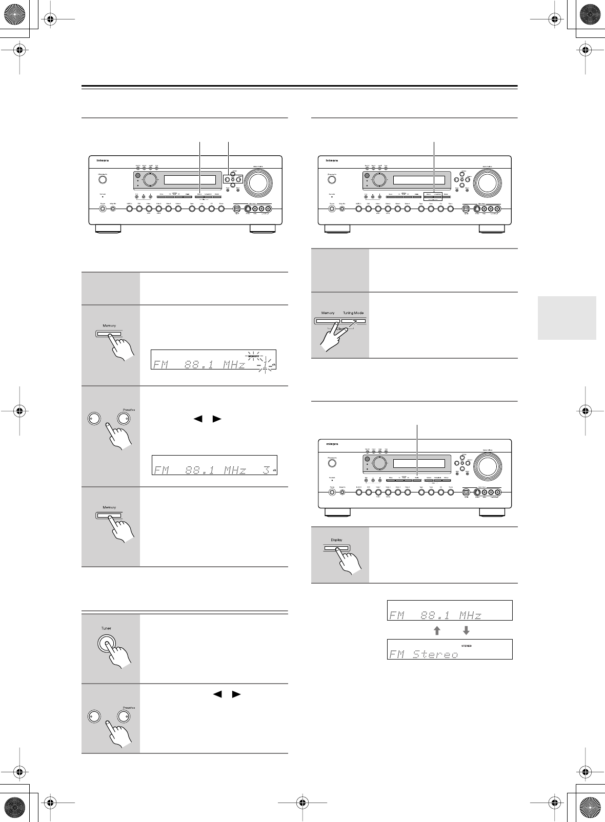
57
Basic Operation
—Continued
Presetting Radio Stations
You can store up to 40 of your favorite radio stations as
presets.
Selecting Preset Stations
Deleting Presets
Displaying Radio Information
1
Tune into the station that you
want to store as a preset.
2
Press the [Memory] button.
The MEMORY indicator appears and
the preset number flashes.
3
While the MEMORY indicator is
displayed (about 8 seconds), use
the Preset [ ]/[ ] buttons to
select a preset from 1 through 40.
In this example, preset #3 is selected.
4
Press the [Memory] button again
to store the station.
The station is stored and the preset
number stops flashing.
Repeat this procedure for all your
favorite radio stations.
1
Use the [TUNER] input selector
button to select either AM or FM.
2
Use the Preset [ ]/[ ] buttons,
or the remote controller’s CH [+/
–] button to select a preset.
Standby
Zone 2
32, 4
1
Select the preset that you want to
delete.
See the previous section.
2
While holding down the [Mem-
ory] button, press the
[Tuning MODE] button.
The selected preset is deleted and its
number disappears from the display.
1
Press the [Display] button
repeatedly to cycle through the
available information.
Standby
Zone 2
2
Standby
Zone 2
2
Band, preset # &
frequency
Listening mode
DTR-6.5,5.5_En.book Page 57 Wednesday, July 28, 2004 9:07 AM
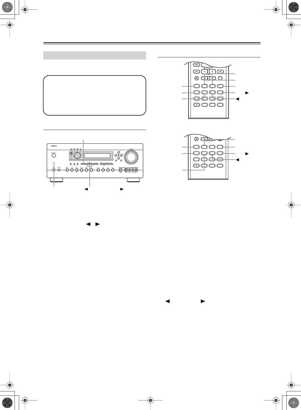
58
Basic Operation
—Continued
See “About the Listening Modes” on page 60 for
detailed information about the listening modes.
Selecting on the AV receiver
■
[Stereo] button
This button selects the Stereo listening mode.
■
Listening Mode [ ] [ ] buttons
These buttons select all the listening modes that can
be used with the current input source.
Modes can be selected in the following order,
depending on the input signal format:
Pure Audio
➔
Direct
➔
Mono
➔
Stereo
➔
Surround
(e.g., PLIIx, Neo:6, Dolby D EX, DTS/DTS 96/24,
DTS-ES, and so on)
➔
Onkyo original DSP
Selecting with the Remote Controller
■
[Surrond] button
This button selects the Dolby Digital, Pro Logic IIx,
Neo:6, DTS, and other listening modes.
■
[All ST] button
This button selects the All Ch Stereo listening mode.
■
[THX] button (DTR-6.5 only)
This button selects the THX listening modes.
■
[Stereo] button
This button selects the Stereo listening mode.
■
[Pure A] button
This button selects the Pure Audio listening mode.
When this mode is selected, the Pure Audio indicator
lights up, the AV receiver outputs no video signals,
and its display is turned off.
■
[Direct] button
This button selects the Direct listening mode.
■
[ DSP] & [DSP ] buttons
These buttons select the Onkyo original DSP modes.
Selecting Listening Modes
• The Dolby Digital and DTS listening modes
can only be selected if your DVD player is
connected to the AV receiver with a digital
audio connection (coaxial or optical).
•Listening mode availability depends on the
format of the current input signal.
Standby
Zone 2
Pure Audio
indicator
Stereo
Listening Mode
Pure A
Display Muting
RandomRec
Last Memory
AngleSubtitleAudio
MemorySearchA-BRepeat
RC-585M
Test Tone
CH SEL
Surround
THX
Direct
StereoAll ST
Level+
Level-
L Night
DSP DSP
Video OffOpen /Close
Re-EQ
Pure A
RandomRec
Last Memory
AngleSubtitleAudio
MemorySearchA-BRepeat
RC-586M
Test Tone
CH SEL
Surround
Direct
StereoAll ST
Level+
Level-
L Night
DSP DSP
Video OffOpen/Close
Cine Fltr
Surround
Pure A
Pure A
Direct
DSP
DSP
Stereo
All ST
THX
Surround
Direct
DSP
DSP
Stereo
All ST
RC-585M
RC-586M
DTR-6.5,5.5_En.book Page 58 Wednesday, July 28, 2004 9:07 AM
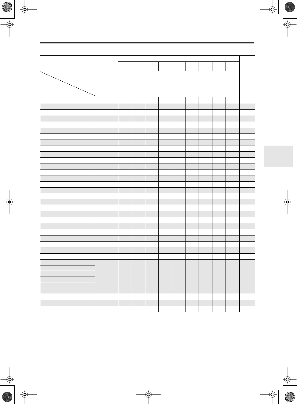
59
Basic Operation
—Continued
The following table lists all the listening modes and shows which modes can be selected for each input signal format.
Input signal format Analog,
PCM*1
1. In the Pure Audio and Direct listening modes, PCM signals at 32 kHz, 44.1 kHz, and 48 kHz are processed at 64 kHz, 88.2 kHz, and 96 kHz respec-
tively. 96 kHz signals are processed at 48 kHz for all listening modes other than Pure Audio, Direct, and Stereo.
Dolby D DTS/DTS 96/24*2
2. In the Pure Audio, Direct, Stereo, and DTS 96/24 listening modes, signals are processed as DTS 96/24. Everything else processed as DTS.
Multich
*/2 2/0 1/0,1+1 Other */2 2/0 1/0,
1+1 Other DTS-
ES
Source CD, TV, LD,
VHS, MD,
turntable,
radio,
cassette,
DTV, etc.
DVD, DTV, etc. DVD, LD, CD, etc. DVD
Listening mode
Pure Audio
❍❍❍❍❍❍❍❍❍❍ ❍
Direct
❍❍ ❍ ❍ ❍ ❍ ❍ ❍ ❍ ❍ ❍
Stereo
❍❍❍❍❍
❍❍❍❍❍
❍
*3
3. DTR-6.5 only.
Mono
❍ ❍ ❍ ❍ ❍ ❍ ❍ ❍ ❍ ❍ ❍
*3
PLIIx Movie/Music/Game *4
4. If the SurrBack parameter is set to “None,” or the Zone 2 speakers are being used, PLII is used.
❍❍ ❍
Neo:6 Cinema
❍ ❍ ❍
Neo:6 Music *5
5. Available only when Surround speakers are connected.
❍❍ ❍
Dolby D
❍ ❍
Dolby D EX *6
6. Cannot be selected if the SurrBack parameter is set to “None” or the Zone 2 speakers are being used.
❍
Dolby D+PLIIx Movie *7
7. Cannot select if the SurrBack ch setting is not set to “2ch,” or the Zone 2 speakers are being used.
❍
Dolby D+PLIIx Music *6
❍
DTS, DTS 96/24
❍ ❍ ❍
*8
8. If the SurrBack setting is set to “None,” or the Zone 2 speakers are being used, DTS is used.
DTS+Neo:6 *6
❍
DTS+Dolby EX *6
❍
DTS+PLIIx Movie *7, Music *6
❍
DTS-ES Discrete *6
Discrete
DTS-ES Matrix *6
Matrix
Multich
❍
Multich+Dolby EX *6
❍
*3
Multich+PLIIx Movie *7, Music *6
❍
*3
*9 PLIIx+THX Cinema *4
9. DTR-6.5 only.
❍❍ ❍
*9 Neo:6+THX Cinema
❍
*9 THX Cinema
❍❍❍❍
❍
*8
❍
*3
*9 THX SurrEX *6
❍ ❍ ❍
*3
*9 PLIIx+THX Cinema *7
❍❍ ❍
*3
*9 DTS+Neo:6+THX Cinema *6
❍
*9 DTS-ES+THX Cinema *6
❍
Mono Movie
❍ ❍ ❍ ❍ ❍ ❍ ❍ ❍ ❍ ❍ ❍
*3
Enhance
Orchestra
Unplugged
Studio-Mix
TV Logic
All Ch Stereo
❍❍❍❍❍❍❍❍❍❍
❍
*3
Full Mono
❍ ❍ ❍ ❍ ❍ ❍ ❍ ❍ ❍ ❍ ❍
*3
Theater-Dimensional
❍❍❍❍❍❍❍❍❍❍
❍
*3
DTR-6.5,5.5_En.book Page 59 Wednesday, July 28, 2004 9:07 AM
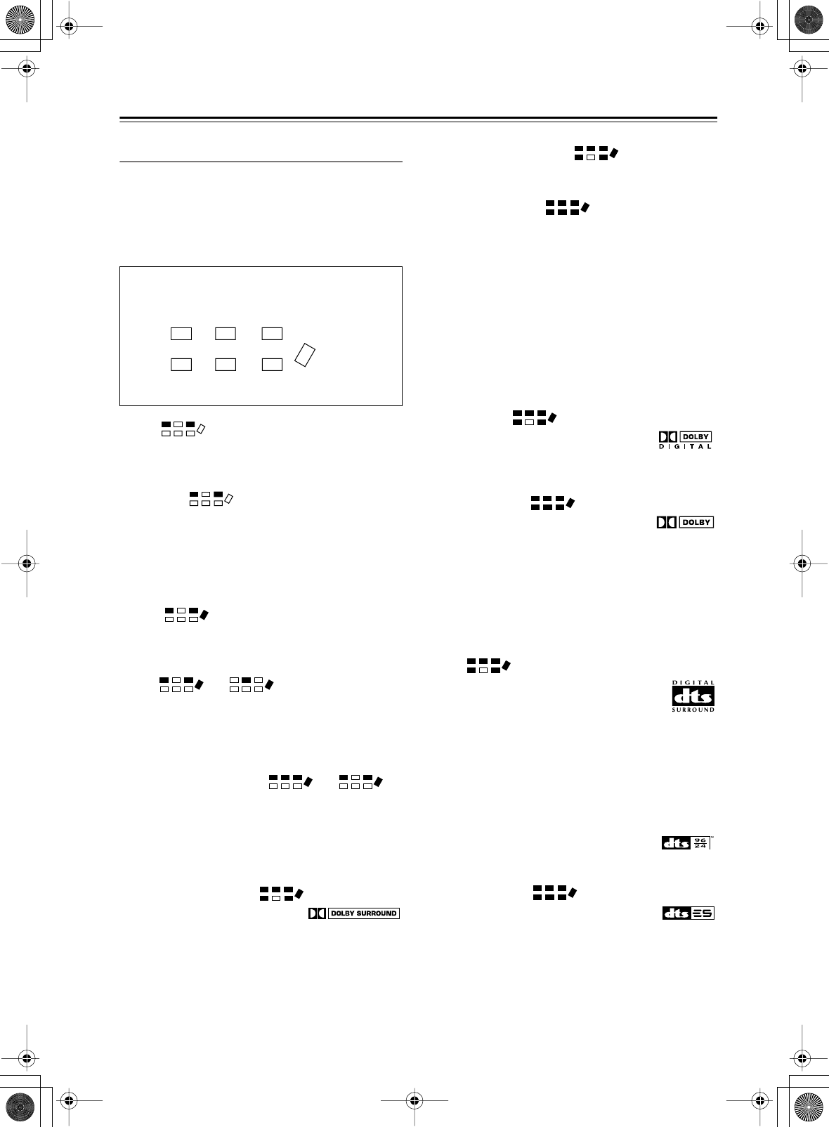
60
Basic Operation
—Continued
About the Listening Modes
With its built-in surround-sound decoders and DSP pro-
grams, the AV receiver can transform your home listen-
ing room into a movie theater or concert hall.
If you connect two surround back speakers (i.e., left and
right), both will be used for 6.1-channel surround play-
back.
Direct
The selected input source is output by the front left and
right speakers only, with minimal processing for a pure
sound.
Pure Audio
As an extension of Direct mode, this mode turns off the
display, turns off the power to the video circuitry, and
minimizes any other possible noise sources, providing a
high fidelity sound that’s true to the original. (Since the
power to the video circuitry is turned off, no video sig-
nals are output while this mode is selected.)
Stereo
The selected input source is processed as a stereo signal
and output by the front left and right speakers and the
subwoofer.
Mono or
Use this mode when watching an old movie with a mono
soundtrack, or to select multilingual soundtracks
recorded in the left and right channels of some movies.
It can also be used when playing a DVD or other source
with multiplexed audio, such as a karaoke DVD.
T-D (Theater-Dimensional) or
With this mode you can enjoy a virtual 5.1 surround
sound even with only two or three speakers. This works
by controlling how sounds reach the listener’s left and
right ears. Good results may not be possible if there’s too
much reverb, so we recommend that you use this mode
in an environment with little or no natural reverb.
Dolby Pro Logic II Movie
Use this mode with DVDs and vid-
eos that bear the Dolby Surround
logo or TV programs that feature Dolby Surround. You
can also use this mode with stereo movies or TV pro-
grams and the AV receiver will create a 5.1 surround mix
from the 2-channel stereo.
Dolby Pro Logic II Music
Use this mode to add 5.1 surround to stereo sources such
as music CDs and DVDs.
Dolby Pro Logic IIx
If you’ve connected surround back speakers to the AV
receiver, Dolby Pro Logic IIx allows you to enjoy 7.1-
channel playback from 2-channel or 5.1-channel music
or movies. Dolby Pro Logic IIx provides a well defined,
natural multichannel surround-sound experience, put-
ting the listener in a seamless envelope of sound. The
added drama and natural sound enhance the listening
experience with CDs, movies, and games.
Dolby Pro Logic IIx has three modes of operation:
Movie mode for movies, Music mode for listening to
music, and Game mode for use with games consoles
with 2-channel stereo outputs.
Dolby Digital
With this format you can experience the
same superb sound that you get at a movie
theater or concert hall. Use this mode with DVDs that
bear the Dolby Digital logo.
Dolby Digital EX
With an added surround-back channel,
this 6.1 channel format offers a heightened
sense of space, for added realism with moving sounds,
such as those that rotate 360 degrees or pass overhead.
Dolby Digital EX material can also be played on conven-
tional 5.1 channel systems, in which case the surround-
back channel audio is split between the surround left and
right channels. Use this mode with DVDs that have a
5.1-channel soundtrack and bear the Dolby Digital logo.
DTS
This digital surround format offers a sur-
round sound experience with exceptional
fidelity. It uses compressed digital audio
data, with six discrete channels (5.1), and the
ability to handle large amounts of audio data while
remaining faithful to the original. DTS provides very
high-quality sound. You’ll need a DTS compatible DVD
player in order to enjoy DTS material. Use this mode
with DVDs, LDs, or CDs that bear the DTS logo.
DTS 96/24
This mode provides higher audio quality.
Use it with CDs, DVDs, and LDs that bear
the DTS 96/24 logo.
DTS-ES Discrete
This is DTS with an added surround back
channel for 6.1 surround sound. Use it with
program material recorded in DTS 6.1 format. With the
additional surround back channel, this format offers 6.1
fully independent digital channels, providing a realistic
sense of movement and space. Use it with program mate-
rial recorded in DTS 6.1, such as CDs, DVDs, or LDs
that bear the DTS-ES logo.
The AV receiver’s surround indicators show which
speakers are active in each listening mode.
Front left Center Front right
Subwoofer
Surround
right
Surround
back left/
right
Surround
left
DTR-6.5,5.5_En.book Page 60 Wednesday, July 28, 2004 9:07 AM
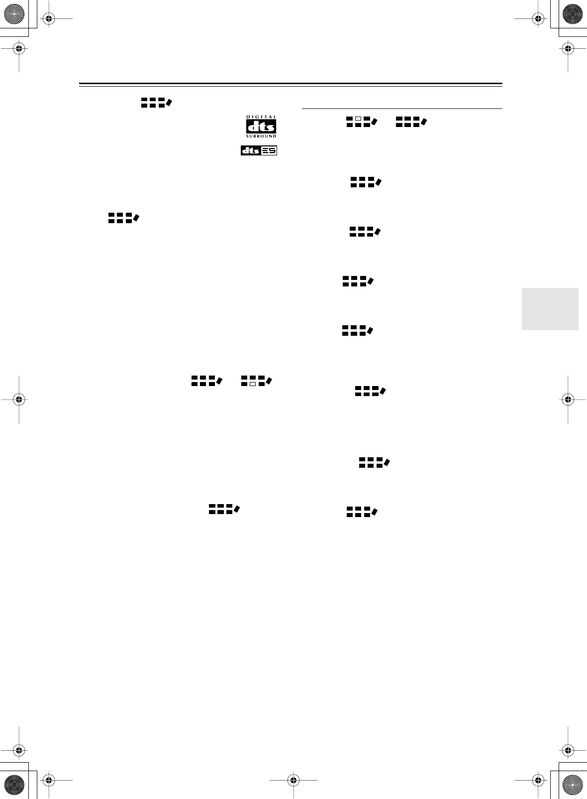
61
Basic Operation
—Continued
DTS-ES Matrix
This is DTS with an added surround back
channel for 6.1 surround sound. Use it to
provide 6.1 channel surround playback
with program material recorded in DTS 5.1
format. Since DTS 5.1 program material
contains surround back channel informa-
tion, all channels can be reconstructed for 6.1-channel
playback. Use this mode with CDs, DVDs, or LDs that
bear the DTS-ES or DTS logo.
Neo:6
This mode provides 6.1-channel playback from 2-chan-
nel sources. It offers six full-bandwidth channels with
excellent separation. There are two modes of operation:
Cinema mode for movies, and Music mode for listening
to music.
Cinema mode simulates the realistic sense of movement
that you get with 6.1-channel surround sound sources.
Use this mode with videos, DVDs, and TV programs that
feature stereo sound.
Music mode uses the surround channels to simulate a
natural sound field that cannot be produced with conven-
tional stereo. Use this mode with stereo material such as
music CDs.
THX Cinema (DTR-6.5 only) or
THX Ltd, founded by George Lucas, develops quality
assurance programs for ensuring that movies are repro-
duced in movie theaters and home theaters just as the
director intended. THX technology is used to eliminate
spatial errors that can occur when a movie soundtrack is
adapted for use in smaller home theaters, ensuring faith-
ful reproduction.
This mode is ideal for watching a movie with a
soundtrack recorded and edited especially for playback
in the spaciousness of a typical movie theater.
THX Surround EX (DTR-6.5 only)
This format was jointly developed by Dolby Laborato-
ries and THX Ltd. especially for home theater use. It’s
based on Dolby Digital EX technology. It adds an extra
surround channel to the existing front left, front right,
center, surround left, surround right, and LFE (sub-
woofer) channels, making a total of 6.1 channels. (For
best results with DVDs that feature THX Surround EX,
use a THX-certified THX speaker system.)
Onkyo Original DSP Modes
Orchestra or
Suitable for classical or operatic music. The center
speaker is turned off and the surround channels are
emphasized in order to widen the stereo image. In addi-
tion, it simulates the natural reverberation of a large hall.
Unplugged
Suitable for acoustic instrument sounds, vocals, and jazz
music. By emphasizing the front stereo image, it simu-
lates the stage-front experience.
Studio-Mix
Suitable for rock and pop music. Listening to music in
this mode creates a lively sound field with a powerful
acoustic image, like being at a club or rock concert.
TV Logic
Adds realistic acoustics to TV programs produced in a
TV studio. In addition, it adds surround effects to the
entire sound and adds clarity to voices.
Enhance
This mode is ideal for enjoying music programs or TV
sports programs. It provides a natural surround sound
with movement in the surround back speakers, creating
a sound with a live feeling to it.
Mono Movie
This mode is suitable for use with old movies and other
mono sound sources. The center speaker outputs the
sound as it is, while reverb is applied to the sound output
by the other speakers, giving presence to even mono
material.
All Ch Stereo
Ideal for background music. The front, surround, and
surround back channels create a stereo image that fills
the entire listening area.
Full Mono
In this mode, all speakers output mono audio, so the
music sounds the same regardless of where you are.
DTR-6.5,5.5_En.book Page 61 Wednesday, July 28, 2004 9:07 AM
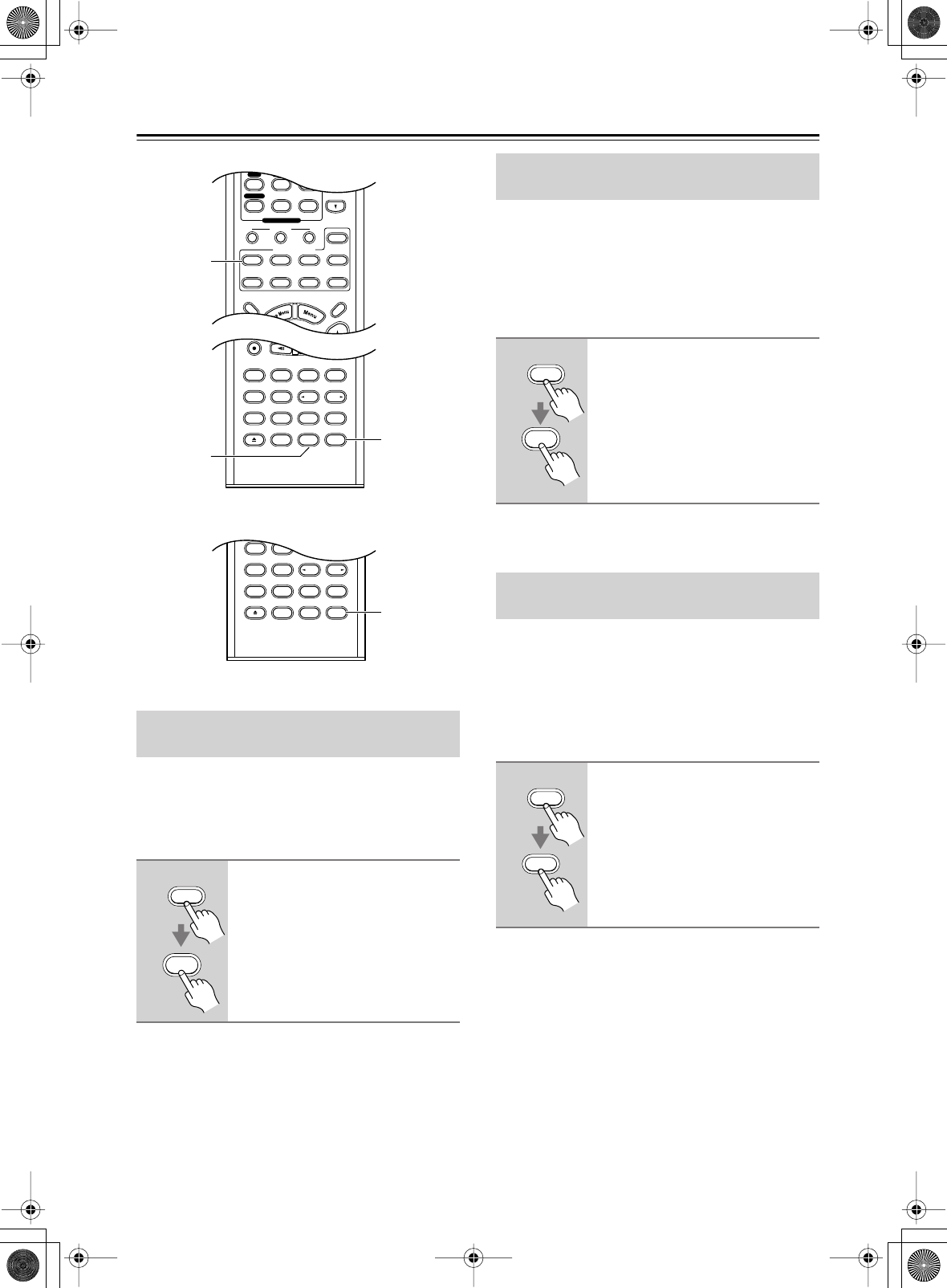
62
Advanced Operation
With the Late Night function, you can reduce the
dynamic range of Dolby Digital material so that you can
still hear quiet parts even when listening at low volume
levels—ideal for watching movies late at night when you
don’t want to disturb anyone.
Notes:
• The effect of the Late Night function depends on the
Dolby Digital material that you are playing, and with
some material there will be little or no effect.
• The Late Night function is set to Off when the AV
receiver is set to Standby.
With the Re-EQ function, you can correct a soundtrack
whose high-frequency content is too harsh, making it
more suitable for home theater viewing. This function
can be used with the following listening modes: Dolby
Digital, Dolby Digital EX, Dolby Pro Logic IIx Movie,
DTS, DTS-ES, DTS Neo:6 Cinema, DTS 96/24,
DTS+Neo:6, and DTS+Dolby EX.
Notes:
• By default, the Re-EQ function is off.
With the CinemaFILTER, you can soften overly bright
movie soundtracks, which are typically mixed for repro-
duction in a movie theater.
CinemaFILTER can be used with the following listening
modes: Dolby Digital, Dolby Digital EX, Dolby Pro
Logic IIx Movie, DTS, DTS-ES, DTS Neo:6 Cinema,
DTS 96/24, DTS+Neo:6, and DTS+Dolby EX.
Using the Late Night Function
(Dolby Digital only)
1
Press the [Receiver] button, and
then press the [L NIGHT] button
repeatedly to select:
Off:
Late Night function off.
Low:
Small reduction in dynamic
range.
High:
Big reduction in dynamic
range.
Pure A
Last Memory
AngleSubtitleAudio
MemorySearchA-BRepeat
RC-586M
Test Tone
CH SEL
Surround
Direct
StereoAll ST
Level+
Level-
L Night
DSP DSP
Video OffOpen/Close
Cine Fltr
Pure A
Rec
Last Memory
AngleSubtitleAudio
MemorySearchA-BRepeat
RC-585M
TV VOL
--
/
---
Dimmer
Tape
TV
Input
Sleep
Test Tone
CH SEL
Surround
THX
Direct
StereoAll ST
Level+
Level-
L Night
DSP DSP
SATTV VCR Cable
DVD
Receiver
CD
+10 0 Clear
456
789
-
Video OffOpen/Close
Macro
123
MD/CDR
Re-EQ
Input Selector
CD
Phono
Tape
Tuner
Remote Mode
Zone 2
Receiver
L Night
Re-EQ
Cine Fltr
(RC-570M, RC-591M)
Receiver
L Night
Using the Re-EQ Function
(DTR-6.5 only)
1
Press the [Receiver] button fol-
lowed by the [Re-EQ] button.
Press the button again to turn off the
Re-EQ function.
Using the CinemaFILTER
(DTR-5.5 only)
1
Press the [Receiver] button, and
then press the [Cine Fltr] button
repeatedly to select:
On:
CinemaFILTER on.
Off:
CinemaFILTER off.
Receiver
Re-EQ
Receiver
Cine Fltr
DTR-6.5,5.5_En.book Page 62 Wednesday, July 28, 2004 9:07 AM
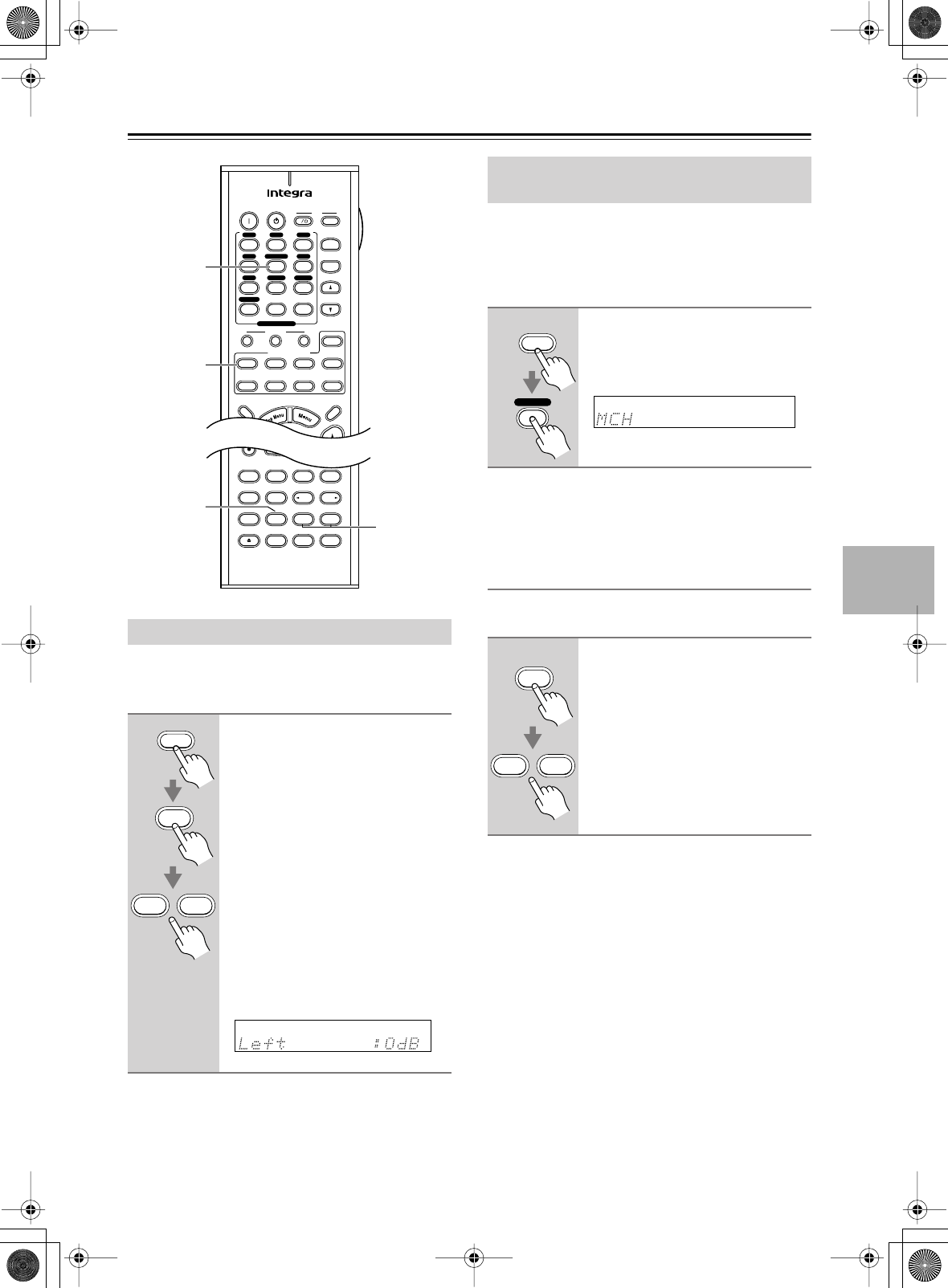
63
Advanced Operation
—Continued
You can adjust the level of individual speakers during
playback. These adjustments are temporary and will be
cancelled when the AV receiver is set to Standby.
Notes:
•You cannot use this function while the AV receiver is
muted.
• Speakers that are set to No or None in the Speaker
Configuration cannot be adjusted.
The DVD analog multichannel input is for connecting
components with a 5.1-channel analog audio output,
such as a DVD player or MPEG decoder.
See “Using a Multichannel Connection” on page 29 for
connection information.
Notes:
•To use the bass and treble functions with the DVD
analog multichannel input, select the Multich listening
mode first.
Adjusting Individual Speaker Levels
You can adjust the level of individual speakers while
using the DVD analog multichannel input.
Notes:
• These speaker level settings are completely indepen-
dent of those explained on pages 50 and left column.
•While the DVD analog multichannel input is selected,
you can only select the Direct, Pure Audio, or Multich
listening mode. If you select the DVD analog multi-
channel input while using another listening mode, that
listening mode will be cancelled.
•While the DVD analog multichannel input is selected,
the Automatic Speaker Setup and Speaker Configura-
tion settings on page 46 are ignored, and signals from
the multichannel input are fed to the front left, front
right, center, surround left, and surround right speak-
ers, and subwoofer regardless of those settings.
•On the DTR-6.5, you can select the listening modes as
explained on page 59. In addition, sound is output by
the surround back speakers.
Adjusting Individual Speaker Levels
1
Press the [Receiver] button, use
the [CH SEL] button to select
each speaker, and use the
[Level–] and [Level+] buttons to
adjust the volume.
Speakers are selected in the following
order: Front Left
→
Center
→
Front
Right
→
Surr Right
→
Surr Back
Right
→
Surr Back Left
→
Surr left
→
Subwoofer.
You can adjust the volume of each
speaker from –12 dB to +12 dB
(–15 dB to +12 dB for the subwoofer).
The name of the currently selected
speaker and its volume appear on the
display, as shown.
Pure A
On Standby TV
Rec
Last Memory
AngleSubtitleAudio
MemorySearchA-BRepeat
RC-585M
TV CH
TV VOL
--
/
---
Dimmer
Tape
TV
Input
Sleep
Input
I
Test Tone
CH SEL
Surround
THX
Direct
StereoAll ST
Level+
Level-
L Night
DSP DSP
SATTV VCR Cable
DVD
Receiver
CD
+10 0 Clear
123
456
789
+
-
Video OffOpen/Close
Macro
123
MD/CDR
Re-EQ
Input Selector
V1V2V3
CD
Phono
Tape
V4DVD
Multi CH
Tuner
Remote Mode
Zone 2
Receiver
CH SEL
Level – +
Multi CH
Receiver
CH SEL
Level+
Level-
Using the DVD Analog Multichannel
Input
1
Press the [Receiver] button fol-
lowed by the [Multi CH] button so
that “MCH” appears on the dis-
play.
1
Use the remote controller’s [CH
SEL] button to select each
speaker, and then use the
[Level–] and [Level+] buttons to
adjust the volume.
The level can be adjusted from –12 to
+12 dB (–30 to +12 dB for the sub-
woofer).
Receiver
Multi CH
CH SEL
Level+
Level-
DTR-6.5,5.5_En.book Page 63 Wednesday, July 28, 2004 9:07 AM
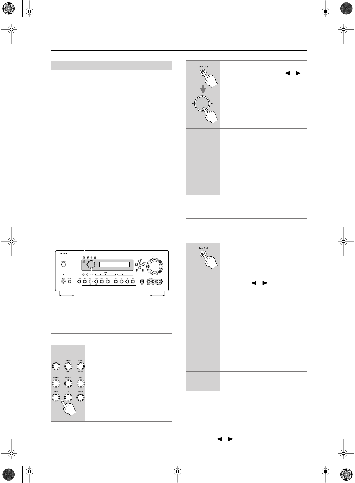
64
Advanced Operation
—Continued
This section explains how to record the current input
source, how to record one input source while enjoying
another, and how to dub audio onto your video record-
ings.
Unless you have the full consent of the copyright
holder, copyright laws prohibit using your recordings
for anything other than personal enjoyment!
Notes:
•The surround sound and DSP listening modes cannot
be recorded.
• Copy-protected DVDs cannot be recorded.
•You cannot record from the DVD analog multichannel
input.
•Various restrictions apply to digital recording. Refer to
the manuals supplied with your digital recording
equipment for more details.
•Digital input signals are output by only the digital out-
puts, and analog input signals are output by only the
analog outputs. There is no internal conversion from
digital to analog or vice versa.
• DTS signals will be recorded as noise, so don’t
attempt analog recording of DTS CDs or LDs.
Recording Audio
You can record the current audio source as follows.
Recording Audio & Watching a Separate
AV Source at the Same Time
While recording audio, you can watch a completely sep-
arate AV Source at the same time. For example, you
could watch a DVD while recording a CD to tape.
Notes:
• Since the Zone 2 function and the REC OUT outputs
use the same circuitry, you cannot record from a sepa-
rate source and use Zone 2 at the same time.
•To turn off the REC OUT output (i.e., the TAPE
OUT), press the [Rec Out] button, and then use the
Controller [ ] [ ] buttons to select “OFF.”
Recording
1
Use the input selector buttons to
select the audio component that
you want to record.
Standby
Zone 2
Rec Out
Input Selector
Controller
2
Press the [Rec Out] button, and
then use the Controller [ ]/[ ]
buttons to select “Rec Sel :
Source.”
The current input source can be
recorded by the recorder connected to
the TAPE OUT.
3
Start recording on the recorder.
See your recorder’s manual for more
information.
4
Start playback on the source
component.
If you select another input source dur-
ing recording, that input source will be
recorded.
1
Press the [Rec Out] button.
2
Within five seconds, use the
Controller [ ]/[ ] buttons to
select the audio input source that
you want to record (you cannot
select TAPE).
The name of the input source selected
for recording appears on the display.
The specified input source can now be
recorded by the recorder connected to
the TAPE OUT.
3
Start recording on the recorder.
See your recorder’s manual for more
information.
4
Start playback on the audio
source component.
DTR-6.5,5.5_En.book Page 64 Wednesday, July 28, 2004 9:07 AM
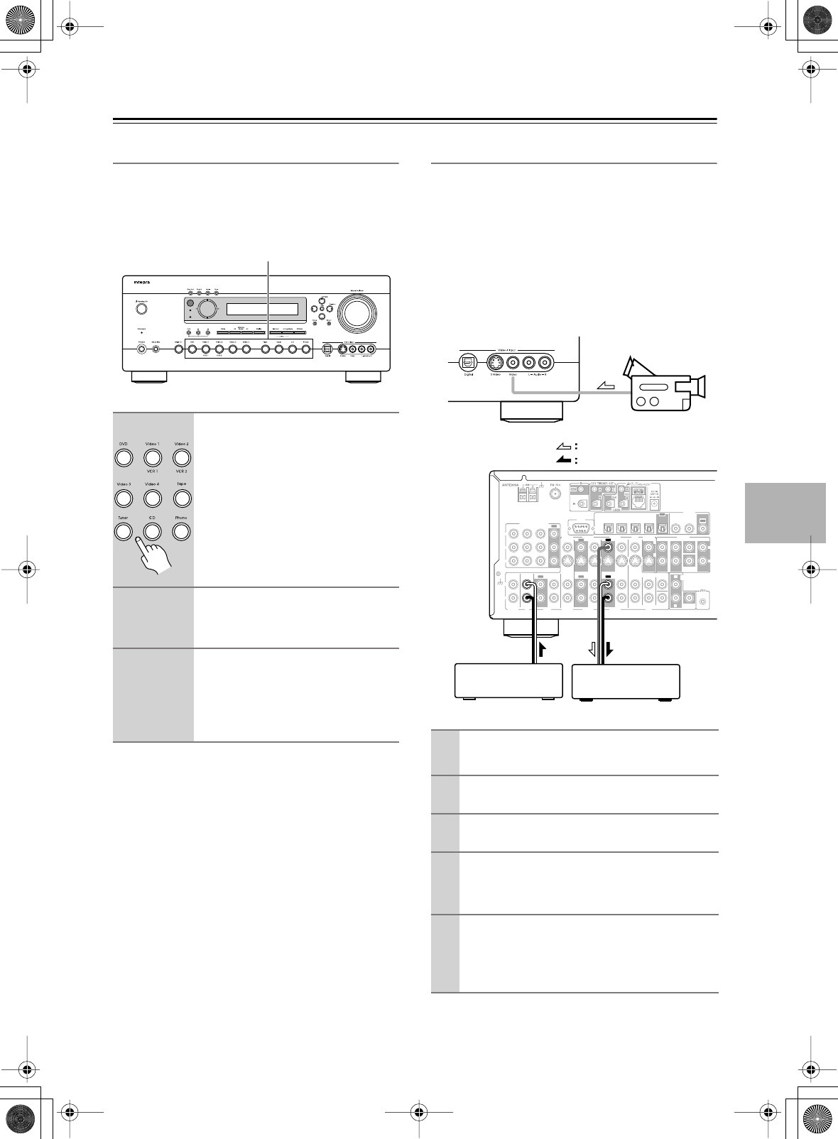
65
Advanced Operation
—Continued
AV Recording
You can record AV input sources to an AV recording
component (VCR, etc) connected to the VIDEO 1 OUT
or VIDEO 2 OUT. See pages 27–38 for information on
connecting components.
Recording Separate AV Sources
Here you can record audio and video from completely
separate sources, allowing you to overdub audio onto
your video recordings. This function takes advantage of
the fact that when an audio-only input source (i.e.,
TAPE, TUNER, or CD) is selected, the video input
source remains unchanged.
In the following example, audio from the CD player con-
nected to the CD IN, and video from the camcorder con-
nected to the VIDEO 4 INPUT VIDEO jack are recorded
by the VCR connected to the VIDEO 1 OUT jacks.
1
Use the input selector buttons to
select the AV component that
you want to record.
Audio signals from the selected input
source are output by the VIDEO 1 OUT
and VIDEO 2 OUT only.
You can watch the source while record-
ing, and the AV receiver’s VOLUME
control has no effect on recording.
2
Start recording on the AV compo-
nent connected to the VIDEO 1
OUT or VIDEO 2 OUT.
3
Start playback on the source AV
component.
If you select another input source dur-
ing recording, that input source will be
recorded.
Standby
Zone 2
1
1
Prepare the camcorder and CD player for
playback.
2
Prepare the VCR for recording.
3
Press the [VIDEO 4] input selector button.
4
Press the [CD] input selector button.
This selects the CD player as the audio source, but
leaves the camcorder as the video source.
5
Start recording on the VCR and start play-
back on the camcorder and CD player.
The video from the camcorder and the audio from
the CD player are recorded by the VCR.
R
L
IN 1IN 2IN 3
FRONT SURR CENTER
FRONT SURR CENTER
SURR BACK
DVD
CD
VIDEO 3 VIDEO 2 VIDEO 1
VIDEO 3 VIDEO 2 PRE OUT
VIDEO 1
IN IN IN
OUT OUT IN IN
OUT
OUT
TAPE
SUB
WOOFER SUB
WOOFER
SUB
WOOFER
MONITOR
OUT
DVD
COMPONENT VIDEO
P
B
Y
P
R
IN OUT IN IN IN
OUT
R
L
R
L
REMOTE
CONTROL
ZONE 2
OUT
V
S
IN 1IN
2
OUT
OPTICAL
IN1IN2IN3IN
4
OUT
COAXIAL
DIGITAL
RS
232
R
L
PHONO
IN
GND
Camcorder
VCRCD player
video signal
audio signal
DTR-6.5,5.5_En.book Page 65 Wednesday, July 28, 2004 9:07 AM
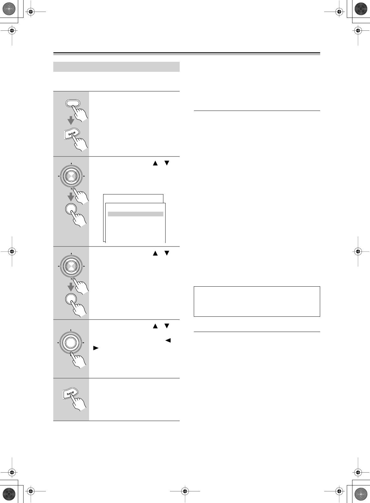
66
Advanced Setup
Here are surround-related settings for PCM, Dolby Dig-
ital, multichannel, and other input signal formats.
Note:
• This procedure can also be performed on the AV
receiver by using its [Setup] button, arrow buttons, and
[Enter] button.
•The Surround Mode and SurrBack Mode settings can
also be changed by using the remote controller’s
[SURR] button.
•The THX Mode settings can also be changed by using
the remote controller’s [THX] button (DTR-6.5 only).
3-1. Analog/PCM
These settings apply to PCM input signals from CD
players and so on, and analog signals from cassette play-
ers, turntables, and so on.
■
a. Input Channel (Mono)
This setting determines which channel is output when
the Mono listening mode is used with a stereo source.
L+R:
Both the left and right channels are output
(default).
Left:
Only the left channel is output.
Right:
Only the right channel is output.
■
b. Surround Mode
This setting determines the surround mode for analog
and PCM input signals. This setting is unavailable if no
center and surround speakers are connected.
You can select PLIIx Movie (default), PLIIx Music,
PLIIx Game, Neo:6 Cinema, or Neo:6 Music.
■
c. THX Mode (DTR-6.5 only)
This setting determines which surround mode is used
when THX is used with analog and PCM input signals.
This setting is unavailable if no surround speakers are
connected.
You can select either PLIIx+THX (default) or
Neo:6+THX.
3-2. Dolby Digital
These settings apply to Dolby Digital input signals.
■
a. LFE Level
With this setting, you can set the level of the LFE (Low
Frequency Effects) channel for Dolby Digital sources to
–
∞
,
–10 dB, or 0 dB (default).
If you find that the low-frequency effects are too loud
when playing Dolby Digital sources, set this to –10 dB
or –
∞
dB.
■
b. Dolby EX
This setting determines how Dolby Digital EX signals
are handled. This setting is unavailable if no surround
back speakers are connected.
Auto:
If the source signal contains a Dolby Digital
EX flag, the Dolby Digital EX listening mode
is used.
Manual:
Depends on the c. SurrBack Mode setting and
d. THX Mode setting.
Decoder Setup
1
Press the [Receiver] button fol-
lowed by the [Setup] button.
The main menu appears onscreen.
2
Use the Up and Down [ ]/[ ]
buttons to select “3. Decoder
Setup,” and then press [Enter].
The Surround Setup menu appears.
3
Use the Up and Down [ ]/[ ]
buttons to select the menu items,
and then press [Enter].
4
Use the Up and Down [ ]/[ ]
buttons to select the settings,
and use the Left and Right [ ]/
[] buttons to set them.
The settings are explained below.
5
When you’ve finished, press the
[Setup] button.
The setup menu closes.
Receiver
Enter
Enter
Menu
------------------------
1.Initial Setup
2.Speaker Setup
Advanced Setup
3.Surround Setup
4.Audio Adjust
5.Listening Mode Preset
6.Preference
Basic Setup
3.Decorder Setup
------------------------
2.Dolby Digital
3.DTS
4.D.F.2ch
5.Multiplex
6.Multich Input
1.Analog/PCM
Enter
Enter
Enter
If you’re not using any surround back speakers, “PLIIx”
will be “PLII.”
If you’re not using any surround speakers, Neo:6 Music
cannot be selected.
DTR-6.5,5.5_En.book Page 66 Wednesday, July 28, 2004 9:07 AM
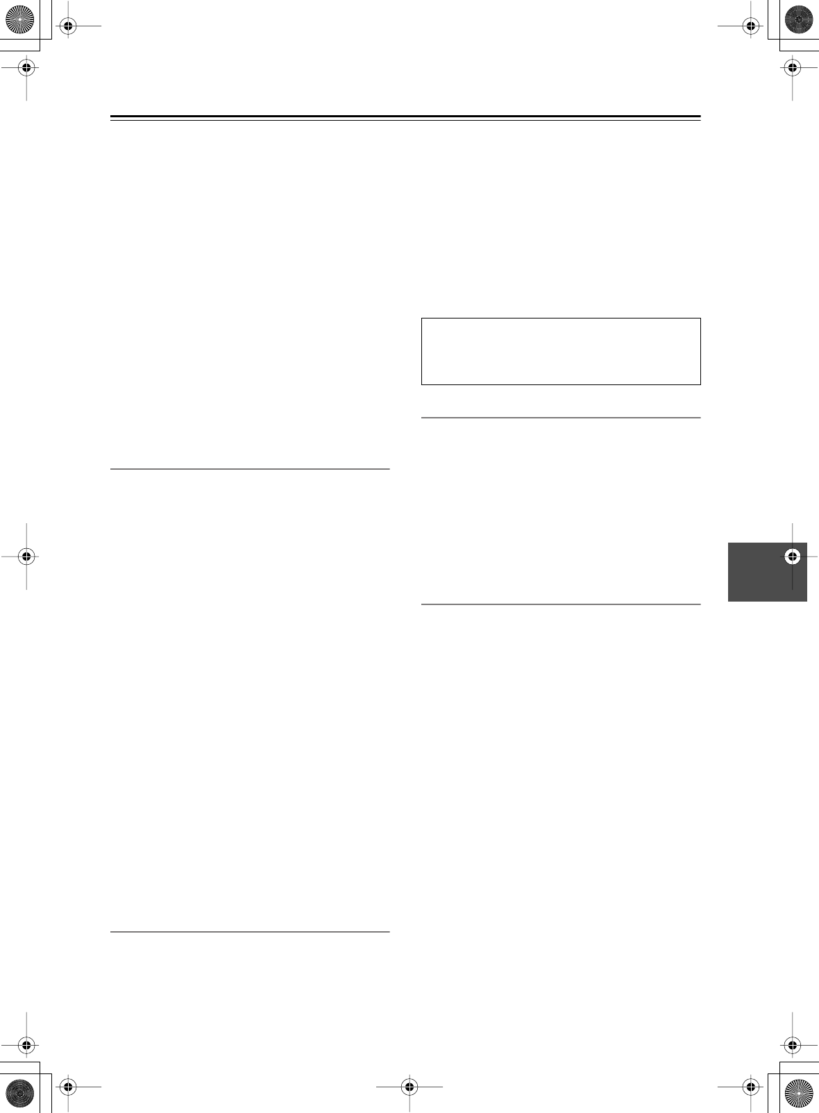
67
Advanced Setup
—Continued
■
c. SurrBack Mode
This setting determines which surround mode is used for
Dolby Digital input signals that don’t contain a Dolby
Digital EX flag, or when the b. Dolby EX setting is set to
Manual. This setting is unavailable if no surround back
speakers are connected.
You can select PLIIx Movie (default), PLIIx Music, or
Dolby D, or Dolby D EX.
•If only one surround back speaker is connected, PLIIx
Movie is unavailable.
■
d. THX Mode (DTR-6.5 only)
This setting determines which surround mode is used
when THX is used with Dolby Digital input signals. This
setting is unavailable if no surround back speakers are
connected.
You can select THX SurrEX (default), PLIIx+THX, or
THX Cinema.
• If only one surround back speaker is connected,
PLIIx+THX is unavailable.
3-3. DTS
These settings apply to DTS input signals.
■
a. LFE Level
With this setting you can set the level of the LFE (Low
Frequency Effects) channel for DTS sources to –
∞
,
–10 dB, or 0 dB (default).
If you find that the low-frequency effects are too loud
when playing DTS sources, set this to –10 dB or –
∞
dB.
■
b. SurrBack Mode
This setting determines which surround mode is used for
DTS input signals that are not DTS-ES. (The handling of
DTS-ES input signals is determined automatically.) This
setting is unavailable if no surround back speakers are
connected.
You can select DTS+Neo:6 (default), Dolby EX, PLIIx
Movie, PLIIx Music, or DTS.
•If only one surround back speaker is connected, PLIIx
Movie is unavailable.
■
c. THX Mode (DTR-6.5 only)
This setting determines which surround mode is used
when THX is used with DTS input signals. This setting
is unavailable if no surround back speakers are con-
nected.
You can select THX SurrEX, Neo:6+THX (default),
PLIIx+THX, or THX Cinema.
• If only one surround back speaker is connected,
PLIIx+THX is unavailable.
3-4. D.F. 2ch
These settings apply to digital input signals, Dolby Dig-
ital and so on, with only 2 channels (2/0).
■
a. Input Channel (Mono)
This setting determines which channel is output when
the Mono listening mode is used with a stereo source.
L+R:
Both the left and right channels are output
(default).
Left:
Only the left channel is output.
Right:
Only the right channel is output.
■
b. Surround Mode
This setting determines the default surround mode for
digital input signals, Dolby Digital and so on, with only
2 channels (2/0). This setting is unavailable if no center
and surround speakers are connected.
You can select PLIIx Movie (default), PLIIx Music,
PLIIx Game, Neo:6 Cinema, or Neo:6 Music.
3-5. Multiplex
This setting applies to multiplex input signals.
■
a. Input Channel
This setting determines which channel is output from a
stereo multiplex source. Use it to select audio channels
or languages with multiplex sources, multilanguage TV
broadcasts, and so on.
Main:
The main channel is output (default).
Sub:
The sub channel is output.
Main/Sub:
Both the main and sub channels are output.
3-6. Multichannel Input
These settings apply to the analog multichannel input.
■
a. Subwoofer Sensitivity
When using the DVD analog multichannel input, the
loudness of the connected subwoofer also depends on
the component that’s connected to that input. If you find
that it’s too loud, set this to 0 dB, +5 dB, +10 dB, or
+15 dB. The default setting is 0 dB.
■
b. SurrBack Mode (DTR-6.5 only)
If you’re using surround back speakers, this setting
determines which surround mode is used with analog
multichannel input signals. This setting is unavailable if
no surround back speakers are connected.
You can select Dolby EX, PLIIx Movie (default), PLIIx
Music, or Multich (straight 5.1-channel playback).
•If only one surround back speaker is connected, PLIIx
Movie is unavailable.
■
c. THX Mode (DTR-6.5 only)
This setting determines which surround mode is used
when THX is used with analog multichannel input sig-
nals. This setting is unavailable if no surround back
speakers are connected.
You can select THX SurrEX (default), PLIIx+THX, or
THX Cinema.
• If only one surround back speaker is connected,
PLIIx+THX is unavailable.
If you’re not using any surround back speakers, “PLIIx”
will be “PLII.”
If you’re not using any surround speakers, Neo:6 Music
cannot be selected.
DTR-6.5,5.5_En.book Page 67 Wednesday, July 28, 2004 9:07 AM
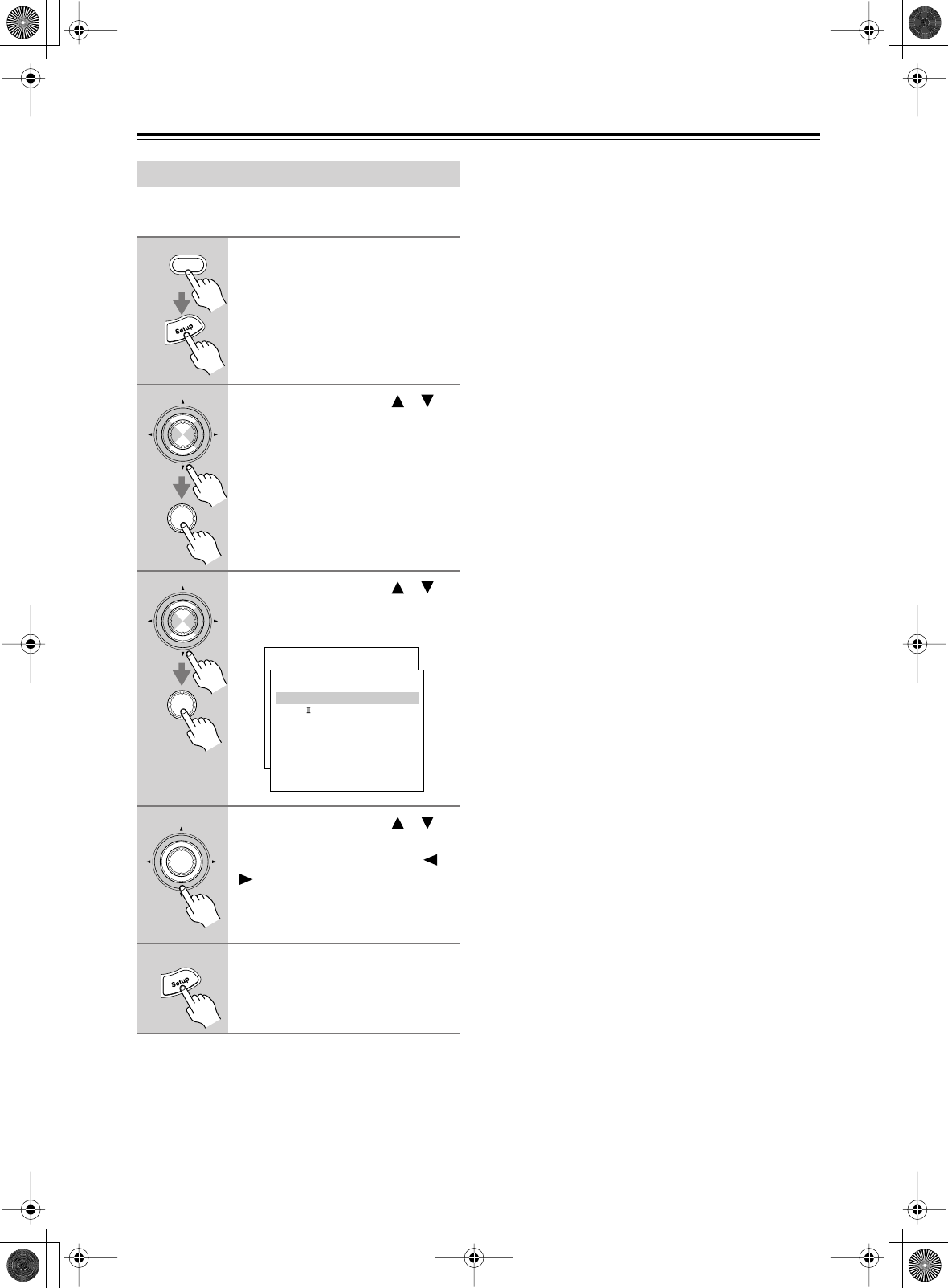
68
Advanced Setup
—Continued
Here you can set listening mode-related settings and
functions.
Note:
• This procedure can also be performed on the AV
receiver by using its [Setup] button, arrow buttons, and
[Enter] button.
Audio Adjust Functions
1
Press the [Receiver] button fol-
lowed by the [Setup] button.
The main menu appears onscreen.
2
Use the Up and Down [ ]/[ ]
buttons to select “4. Audio
Adjust,” and then press [Enter].
The Audio Adjust menu appears.
3
Use the Up and Down [ ]/[ ]
buttons to select menu items,
and then press [Enter].
4
Use the Up and Down [ ]/[ ]
buttons to select the settings,
and use the Left and Right [ ]/
[] buttons to set them.
The settings are explained below.
5
When you’ve finished, press the
[Setup] button.
The setup menu closes.
Receiver
Enter
Enter
Enter
Enter
Menu
------------------------
1.Initial Setup
2.Speaker Setup
Advanced Setup
3.Surround Setup
4.Audio Adjust
5.Listening Mode Preset
6.Preference
Basic Setup
4.Audio Adjust
------------------------
2.PL x/Neo:6
3.Enhance
4.Orchestra
5.Unplugged
6.Studio-Mix
7.TV Logic
8.Mono Movie
9.Theater-Dimensional
1.Mono
Enter
DTR-6.5,5.5_En.book Page 68 Wednesday, July 28, 2004 9:07 AM

69
Advanced Setup
—Continued
4-1. Mono
■
a. Output Channel
This setting determines which speakers are used to out-
put mono audio when the Mono listening mode is used.
L/R:
Mono audio is output from the front left and
right speakers (default).
Center:
Mono audio is output from the center speaker.
■
b. Academy (DTR-6.5 only)
Early movies had a mono soundtrack that suffered from
audible hiss and a poor high-frequency response due to
the quality of the film. To improve matters, the high-fre-
quencies were boosted before being recorded onto film,
and then attenuated to their original levels during play-
back in the movie theater. Some old movies have been
transferred to newer distribution media without the high
frequencies being attenuated, creating a harsh sound
with pronounced hiss. With the Academy Filter, which is
based on the playback techniques used in those days, you
can attenuate those high-frequencies to their original lev-
els and enjoy the movie as it was intended to be heard.
On:
Academy Filter on.
Off:
Academy Filter off (default).
4-2. PLIIx/Neo:6
If no surround back speakers are connected, this item
will be “PLII/Neo:6” instead of “PLIIx/Neo:6.”
■
a. Panorama
With this function, you can broaden the width of the
front stereo image when using the Dolby Pro Logic IIx
Music listening mode.
On:
Panorama function on.
Off:
Panorama function off (default).
■
b. Dimension
With this setting, you can move the sound field forward
or backward when using the Dolby Pro Logic IIx Music
listening mode. The default setting is 3. Higher settings
move the sound field forward. Lower settings move it
backward.
If the stereo image feels too wide, or there’s too much
surround sound, move the sound field forward to
improve the balance. Conversely, if the stereo image
feels like it’s in mono, or there’s not enough surround
sound, move it backward.
■
c. Center Width
With this function, you can adjust the width of the sound
from the center speaker when using the Dolby Pro Logic
IIx Music listening mode. If you’re using a center
speaker, with Dolby Pro Logic IIx, the center channel
sound is output by only the center speaker. (If you’re not
using a center speaker, the center channel sound will be
distributed to the front left and right speakers to create a
phantom center). This setting controls the front left,
right, and center mix, allowing you to adjust the weight
of the center channel sound. It can be adjusted from 0 to
7 (default is 3).
■
d. Center Image
The DTS Neo:6 Music listening mode creates 6-channel
surround sound from 2-channel (stereo) sources. With
this setting, you can specify by how much the front left
and right channel output is attenuated in order to create
the center channel. It can be adjusted from 0 to 5 (default
is 3).
When set to 0, the front left and right channel output is
attenuated by half (–6 dB), giving the impression that the
sound is located centrally. This setting works well when
the listening position is considerably off center. When
set to 5, the front left and right channels are not attenu-
ated, maintaining the original stereo balance.
4-3. Enhance, 4-4. Orchestra, 4-5.
Unplugged, 4-6. Studio-Mix, 4-7. TV Logic
& 4-8. Mono Movie
These settings apply to the Onkyo original DSP listening
modes.
■
a. Front Effect
With this setting, you can turn off the reverb for the front
speakers. This is useful when playing live material that
already contains live reverberation and the reverb added
by the DSP listening mode simply blurs the original
sound. When the Front Effect is turned off, no reverb is
added to the front left, right, and center speakers and the
original reverberation can be heard as it is.
On:
Front Effect on (default).
Off:
Front Effect off.
■
b. Reverb Level
With this setting, you can adjust the amount of reverb to
suit your listening environment, source material, and so
on. The available settings are: Low, Middle (default),
and High.
■
c. Reverb Time
With this setting, you can adjust the reverb time to suit
your listening environment, source material, and so on.
The available settings are: Short, Middle (default), and
Long.
DTR-6.5,5.5_En.book Page 69 Wednesday, July 28, 2004 9:07 AM
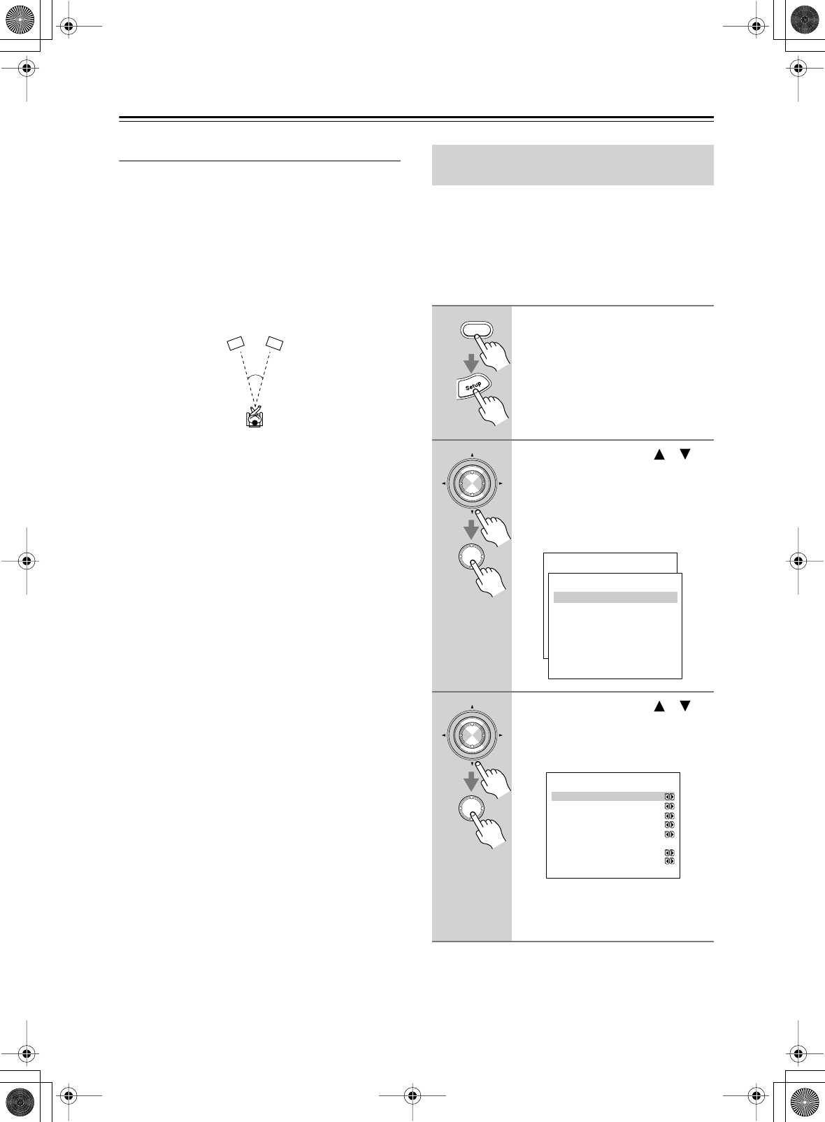
70
Advanced Setup
—Continued
4-9. Theater-Dimensional
These settings apply to the Theater-Dimensional listen-
ing mode.
■
a. Listening Angle
With this setting, you can specify the angle of the front
left and right speakers relative to the listening position.
Processing for the Theater-Dimensional listening mode
is based on this setting. Ideally, the front left and right
speakers should be equidistant from the listening posi-
tion and at an angle close to one of the two available set-
tings.
20º:
Select if the listening angle is 20 degrees.
40º:
Select if the listening angle is 40 degrees
(default).
■
b. Center
With this setting, you can specify whether or not you’re
using a center speaker. If you are, the center channel
sound will be output by the center speaker when using
the Theater-Dimensional listening mode. This reduces
the workload of the front left and right speakers, and cre-
ates a more articulate sound space. In this case, the set-
tings for the distance between the listening position and
each speaker, and the level of each speaker are impor-
tant, but making these settings is a breeze with the Auto-
matic Speaker Setup function (see page 39).
On:
Select if using a center speaker.
Off:
Select if not using a center speaker (default).
■
c. Front Expand
With the Front Expander function, you can broaden the
width of the front stereo image. This can be useful with
narrow listening angles of 20 degrees or less.
On:
Front Expander function on.
Off:
Front Expander function off (default).
■
d. Dialog Enhance
With this function, you can improve the clarity of the
center channel, which usually contains dialog.
On:
Dialog Enhance function on.
Off:
Dialog Enhance function off (default).
■
e. Virtual Surr Level
With this setting, you can adjust the level of virtual sur-
round sound from –3 dB to +3 dB (default is 0 dB). If the
clarity is poor, or the effect sounds unnatural, you may
be able to improve it by lowering this setting.
You can assign a default listening mode to each input
source that will be selected automatically when you
select each input source. For example, you can set the
default listening mode to be used with Dolby Digital
input signals. You can select other listening modes dur-
ing playback, but the mode specified here will be
resumed once the AV receiver has been set to Standby.
20/40˚
Front right speaker
Front left speaker
Assigning Listening Modes to Input
Sources
1
Press the [Receiver] button fol-
lowed by the [Setup] button.
The main menu appears onscreen.
2
Use the Up and Down [ ]/[ ]
buttons to select “5. Listening
Mode Preset,” and then press
[Enter].
The Listening Mode Preset menu
appears.
3
Use the Up and Down [ ]/[ ]
buttons to select the input selec-
tor that you want to set, and then
press [Enter].
For input selectors that have no digital
input jacks, only “a. Analog” will be
available.
Receiver
Enter
Enter
Menu
------------------------
1.Initial Setup
2.Speaker Setup
Advanced Setup
3.Surround Setup
4.Audio Adjust
5.Listening Mode Preset
6.Preference
Basic Setup
5.Listening Mode Preset
------------------------
2.VIDEO1
3.VIDEO2
4.VIDEO3
5.VIDEO4
6.TAPE
7.TUNER
8.CD
9.PHONO
1.DVD/MULTICH
Enter
Enter
5-1.ListeningModePreset
a.Ana/PCM :Last Valid
----- DVD/MULTICH ------
b.Dolby D :Last Valid
c.DTS :Last Valid
d.D.F.2ch :Last Valid
e.D.F.Mono:Last Valid
f.Multiplex
:Last Valid
g.Multich :Last Valid
DTR-6.5,5.5_En.book Page 70 Wednesday, July 28, 2004 9:07 AM
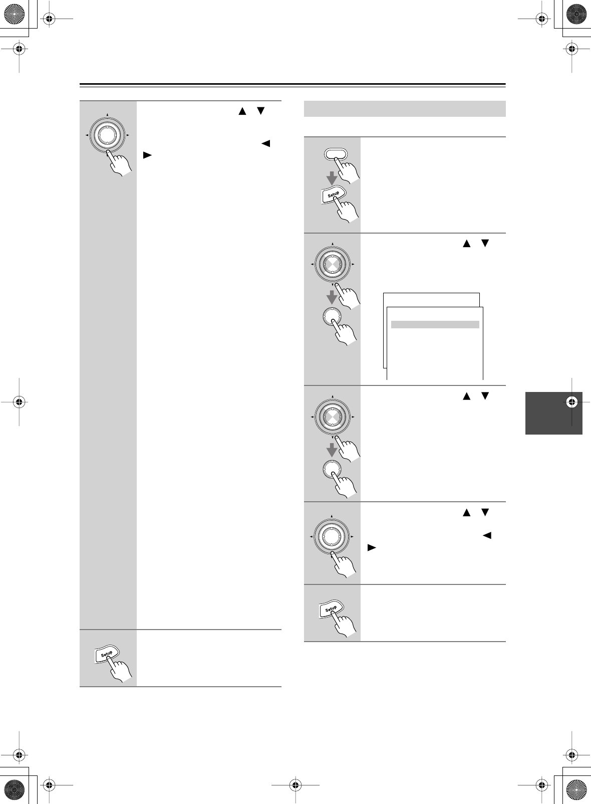
71
Advanced Setup
—Continued
Note:
• This procedure can also be performed on the AV
receiver by using its [Setup] button, arrow buttons, and
[Enter] button.
This section explains the items on the Preference menu.
Note:
• This procedure can also be performed on the AV
receiver by using its [Setup] button, arrow buttons, and
[Enter] button.
4
Use the Up and Down [ ]/[ ]
buttons to select the signal for-
mat that you want to set, and
then use the Left and Right [ ]/
[] buttons to select a listening
mode.
Only listening modes that can be used
with each input signal format can be
selected.
For “Surround” or “THX,” the listening
mode specified on pages 66, 67 will be
used.
The Last Valid option means that the
listening mode selected last will be
used.
a. Ana/PCM:
With this setting, you
can specify the listening mode to be
used when an analog (CD, TV, LD,
VHS, MD, turntable, radio, cassette,
cable, satellite, etc) or PCM digital
(CD, DVD, etc) audio signal is played.
b. Dolby D:
With this setting, you can
specify the listening mode to be used
when a Dolby Digital format digital
audio signal is played (DVD, etc).
c. DTS:
With this setting, you can spec-
ify the listening mode to be used when
a DTS format digital audio signal is
played (DVD, LD, CD, etc).
d. D.F. 2ch:
With this setting, you can
specify the listening mode to be used
when a 2-channel (2/0) digital audio
signal (Dolby Digital, DTS) is played
(DVD, etc).
e. D.F. Mono:
With this setting, you
can specify the listening mode to be
used when a mono digital audio signal
is played (DVD, etc).
f. Multiplex:
With this setting, you can
specify the listening mode to be used
when a multiplex audio signal is
played.
g. Multich:
This setting is available
only when “5-1. DVD/MULTCH” is
selected. With this setting, you can
specify the listening mode to be used
when the DVD analog multichannel
input is used.
5
When you’ve finished, press the
[Setup] button.
The setup menu closes.
Enter
Setting Preferences
1
Press the [Receiver] button fol-
lowed by the [Setup] button.
The main menu appears onscreen.
2
Use the Up and Down [ ]/[ ]
buttons to select “6. Preference,”
and then press [Enter].
The Preference menu appears.
3
Use the Up and Down [ ]/[ ]
buttons to select menu items,
and then press [Enter].
4
Use the Up and Down [ ]/[ ]
buttons to select the settings,
and use the Left and Right [ ]/
[] buttons to set them.
The settings are explained below.
5
When you’ve finished, press the
[Setup] button.
The setup menu closes.
Receiver
Enter
Enter
Menu
------------------------
1.Initial Setup
2.Speaker Setup
Advanced Setup
3.Surround Setup
4.Audio Adjust
5.Listening Mode Preset
6.Preference
Basic Setup
6.Preference
------------------------
2.Volume Setup
3.OSD Setup
4.Remote Setup
5.Digital Format
6.12V Trigger A Setup
7.12V Trigger B Setup
8.12V Trigger C Setup
1.IntelliVolume
Enter
Enter
Enter
DTR-6.5,5.5_En.book Page 71 Wednesday, July 28, 2004 9:07 AM

72
Advanced Setup
—Continued
6-1. IntelliVolume
With this preference, you can set the input level for each
input source. This is useful if some of your AV compo-
nents are louder or quieter than others.
While this preference is shown onscreen, you can select
each input source and set the levels while listening to and
comparing them.
If a component is too loud compared to your other com-
ponents, use the Left [ ] button to adjust the level. If it’s
too quiet, use the Right [ ] button.
• The level can be set from –12 dB to +12 dB.
6-2. Volume Setup
■
a. Volume Display
With this preference, you can choose how the volume
level is displayed.
Absolute:
Display range is MIN, 1 through 99, MAX.
Relative:
Display range is –
∞
dB, –81 dB, –80 dB
through +18 dB.
The absolute value 82 is equivalent to the relative value
0 dB.
■
b. Maximum Volume
With this preference, you can prevent the volume being
set too high by specifying a maximum volume level.
When the Volume Display preference is set to Absolute,
the range is from 50 to 99. When it’s set to Relative, the
range is –32 dB through +17 dB. To specify no maxi-
mum volume, select Off.
■
c. Power On Volume
With this preference, you can specify the volume setting
to be used each time the AV receiver is turned on.
When the a. Volume Display preference is set to Abso-
lute, the range is MIN, 1 through 99, or MAX. When it’s
set to Relative, the range is –
∞
dB, –81 dB through
+18 dB.
To use the same volume level that was used when the AV
receiver was turned off, select Last.
The Power On Volume cannot be set higher than the
maximum volume specified with the b. Maximum Vol-
ume setting.
■
d. Headphones Level
With this preference, you can specify the headphone vol-
ume relative to the main volume. This is useful if there’s
a volume difference between your speakers and your
headphones. The headphone volume can be set between
–12 dB and +12 dB.
6-3. OSD Setup
■
a. Immediate Display
This preference determines whether or not actions, such
as selecting an input source, are displayed onscreen.
Normal:
Actions displayed. Select this if you have a
standard 4:3 TV.
Wide:
Actions displayed. Select this if you have a
widescreen 16:9 TV.
Off:
Actions not displayed.
Even if this preference is set to Normal or Wide, actions
are not displayed on the TV or projector that’s connected
to the COMPONENT VIDEO OUT.
■
b. Scan Mode
If the text in onscreen setup menus flickers due to com-
patibility with the connected display device (TV, projec-
tor, etc), set the Scan Mode to Non-Interlaced.
Interlaced:
Default.
Non-Interlaced:
Select if the text flickers.
• Depending on the display device, when Non-Inter-
laced is selected, the onscreen setup menus may not
appear. If this happens, use the AV receiver’s display
and repeat the procedure to revert to Interlaced.
6-4. Remote Setup
■
a. Remote ID
With this setting, you can change the AV Receiver’s
remote control ID. You may need to change this if the
remote controller’s control codes overlap with those of
another Integra component located in the same room.
•If you change the AV receiver’s remote control ID, be
sure to set the same ID on both the AV receiver and
remote controller (see right column). The default ID
for both is 1.
■
b. IR IN Position
When using a commercially available IR receiver, use
this setting to specify its location.
Main:
Select if the IR receiver is located in the main
room.
Zone 2:
Select if the IR receiver is located in, and will
be used to control Zone 2.
DTR-6.5,5.5_En.book Page 72 Wednesday, July 28, 2004 9:07 AM
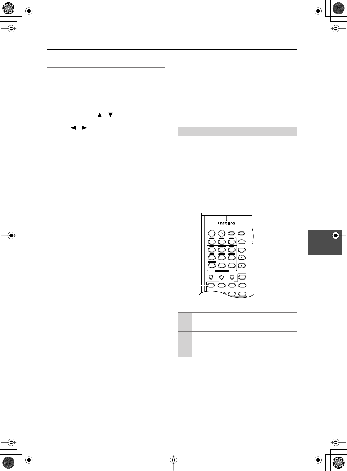
73
Advanced Setup
—Continued
6-5. Digital Format
■
b. Digital Format
This setting does not apply to input selectors not
assigned to a digital input jack.
With this setting, you can set a digital input to DTS,
PCM, or Auto. This can be set for each input selector
individually.
Use the Up and Down [ ]/[ ] buttons to select the
input selector that you want to set, and then use the Left
and Right [ ]/[ ] buttons to select:
Auto:
PCM, Dolby Digital, and DTS formats are
accepted. If no digital signal is present, the ana-
log input is used.
DTS:
Select this option if playing a DTS CD with the
Auto option produces noise while the AV
receiver is identifying the DTS signal, or when
using fast forward or fast reverse. Nothing is
output if the input signal is not DTS.
PCM:
Select this option if playing a CD or other PCM
source with the Auto option causes the tops of
tracks to be clipped. Nothing is output if the
input signal is not PCM.
• If there is no digital connection, only Auto appears.
•Select Auto or DTS when playing a DTS CD or LD. If
you select PCM, only noise will be heard.
6-6., 6-7., 6-8. 12V Trigger Setup
When the AV receiver’s 12 V TRIGGER OUT A/B/C
jack is connected to the 12 V TRIGGER IN jack on a
connected component, you can specify whether or not a
12-volt trigger signal is output when that component is
selected as the source for the main room, Zone 2, or
both.
By default, on the Trigger A Setup menu, all input
sources are set to Main. On the Trigger A and B Setup
menus, all input sources are set to Off.
Off:
No trigger signal is output.
Main:
Select this if you want to output a 12-volt trig-
ger signal when a connected component is
selected as the source for the main room.
Zone2:
Select this if you want to output a 12-volt trig-
ger signal when a connected component is
selected as the source for Zone 2.
Main/Zone2:
Select this if you want to output a 12-volt
trigger signal when a connected component is
selected as the source for either the main room
or Zone 2.
■
Delay
When several components are turned on simultaneously
via the 12-volt triggers, depending on the type of compo-
nents, a large amount of current may be drawn momen-
tarily. To prevent this, you can delay the trigger signals
output by the AV receiver. In addition, by delaying the
trigger signal for your power amplifier so that it’s the last
component to be turned on, you can avoid the “thump”
noise that’s sometimes heard when a source component
is turned on.
The delay determines how long after the input source is
changed on the AV receiver the trigger signal is output,
and can be set to 0 sec, 1 sec, 2 sec, or 3 sec. When set to
0 sec, the trigger signal is output as soon as the input
source is changed.
If several Integra components are used in the same room,
the remote controller’s control codes may overlap with
those of another component. To differentiate the remote
controller’s control codes, you can change its ID to
another number.
Notes:
If you change the remote controller’s ID, be sure to set
the same ID on both the remote controller and AV
receiver (see 6-4. Remote Setup in the left column). The
default ID for both is 1.
Changing the Remote Controller’s ID
1
Press and hold down the [Receiver] but-
ton, and then press the TV [Input] button.
2
Use the number buttons to enter a remote
control ID.
You can enter 1, 2, or 3.
On Standby TV
TV CH
TV VOL
--
/
---
Dimmer
Tape
Sleep
Input
I
SATTV VCR Cable
DVD
Receiver
CD
+10 0 Clear
123
456
789
+
-
Macro
123
MD/CDR
Input Selector
V1V2V3
CD
Phono
Tape
V4DVD
Multi CH
Tuner
Remote Mode
Zone 2
1
1
Number
buttons
DTR-6.5,5.5_En.book Page 73 Wednesday, July 28, 2004 9:07 AM
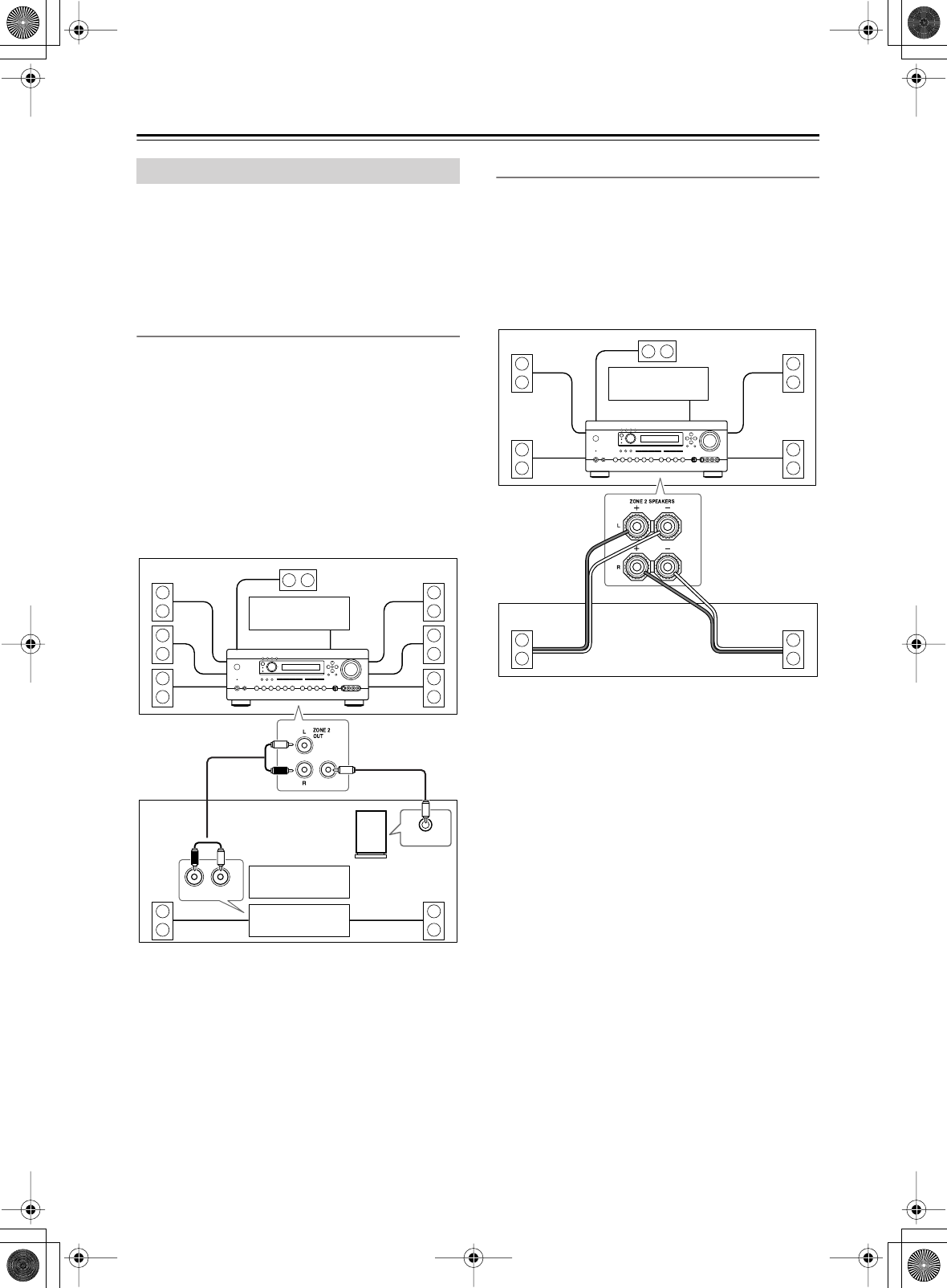
74
Zone 2
With the Zone 2 function, you can enjoy one input
source in the main room and a different source in another
room.
There are two connection methods: using a receiver/inte-
grated amp in Zone 2 or using only a pair of speakers in
Zone 2.
Using a Receiver/Integrated Amp in Zone 2
With this connection method, you can use 7.1 surround
sound in the main room and play a different AV source in
Zone 2. The volume for Zone 2 is set on the receiver/
integrated amp.
•Use an RCA audio cable to connect the AV receiver’s
ZONE 2 OUT L/R jacks to an analog audio input on
your receiver/integrated amp.
• DTR-6.5 only: Connect the AV receiver’s ZONE 2
OUT SUBWOOFER jack to the subwoofer in Zone 2.
•Connect the Zone 2 speakers to the speaker terminals
on the receiver/integrated amp.
The AV receiver’s ZONE 2 OUT jacks can also be used
as pre outs, although, in this case, the volume cannot be
controlled solely on the connected amplifier. See “Set-
ting the Zone 2 Out” on page 76 for details.
Using Only Speakers in Zone 2
With this connection method, you can use 5.1 surround
sound in the main room and play a different AV source in
Zone 2. The volume for Zone 2 is set on the AV receiver.
• Set the Powered Zone 2 setting to Activated (see
page 75).
• Connect your Zone 2 speakers to the AV receiver’s
ZONE 2 SPEAKERS terminals.
Connecting Zone 2
RL
IN
SUB
WOOFER
LINE INPUT
Main room
Zone 2
TV
TV
Receiver/
integrated amp
AV receiver
Subwoofer
(DTR-6.5 only)
LR
Main room
TV
Zone 2
AV receiver
DTR-6.5,5.5_En.book Page 74 Wednesday, July 28, 2004 9:07 AM
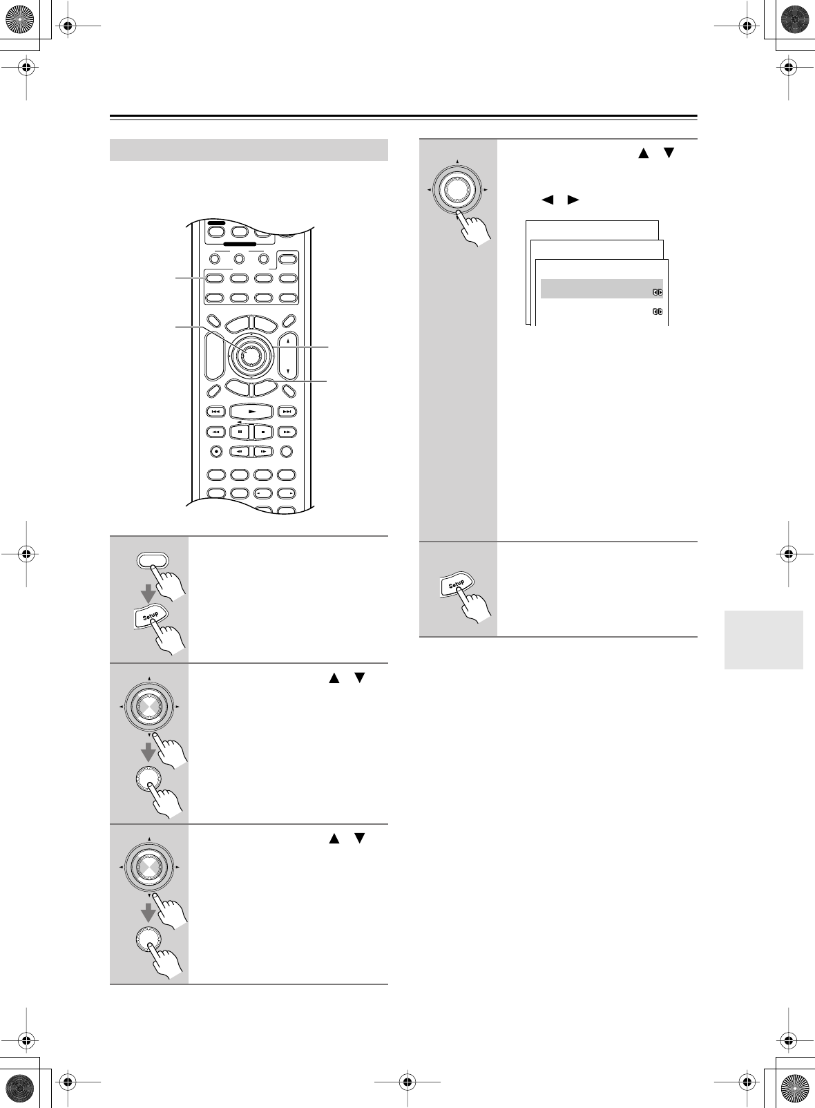
75
Zone 2
—Continued
To use Zone 2, you must make this setting. It enables the
speakers connected to the ZONE 2 SPEAKERS termi-
nals so that they produce sound when Zone 2 is used.
Note:
• This procedure can also be performed on the AV
receiver by using its [Setup] button, arrow buttons, and
[Enter] button.
Setting the Powered Zone 2
1
Press the [Receiver] button fol-
lowed by the [Setup] button.
The main menu appears onscreen.
2
Use the Up and Down [ ]/[ ]
buttons to select “1. Initial
Setup,” and then press [Enter].
The Initial Setup menu appears.
3
Use the Up and Down [ ]/[ ]
buttons to select “3. Hardware
Setup,” and then press [Enter].
The Hardware Setup menu appears.
Pure A
Display Muting
RandomRec
Last Memory
AngleSubtitleAudio
MemorySearchA-BRepeat
E
x
i
t
G
u
i
d
e
Prev
CH
TV VOL
--
/
---
Dimmer
Tape
TV
Input
Sleep
Enter
Test Tone
CH SEL
Surround
THX
Direct
StereoAll ST
Level+
Level-
LNi ht
DSP DSP
T
o
p
M
e
n
u
M
e
n
u
S
e
t
u
p
R
e
t
u
r
n
VOL
CH
Disc
SATTV VCR Cable
DVD
Receiver
CD
+10 0 Clear
789
Video OffOpen/Close
Macro
123
MD/CDR
Re EQ
+
-
Input Selector
Phono
Remote Mode
Zone 2
2–4
2, 3
1, 5
1
Receiver
Enter
Enter
Enter
Enter
4
Use the Up and Down [ ]/[ ]
buttons to select “a. Powered
Zone 2,” and use the Left and
Right [ ]/[ ] buttons to select:
Not Activated:
Zone 2 SPEAKERS
terminals deactivated.
Activated:
Zone 2 SPEAKERS termi-
nals activated.
When Zone 2 is activated and turned on
(see page 77), the speakers connected
to the ZONE 2 SPEAKERS terminals
output sound, but the speakers con-
nected to the SURROUND BACK
SPEAKERS terminals do not. (When
Zone 2 is activated but not used, the
surround back speakers work as nor-
mal.)
5
Press the [Setup] button.
The setup menu closes.
Enter
Menu
------------------------
1.Initial Setup
2.Speaker Setup
Advanced Setup
3.Surround Setup
4.Audio Adjust
5.Listening Mode Preset
6.Preference
Basic Setup
1.Initial Setup
------------------------
2.Component Video
3.Hardware Setup
1.Digital Input
1-3.Hardware Setup
------------------------
:Not Activated
b.Zone2 Out
:Fixed
a.Powered Zone2
DTR-6.5,5.5_En.book Page 75 Wednesday, July 28, 2004 9:07 AM
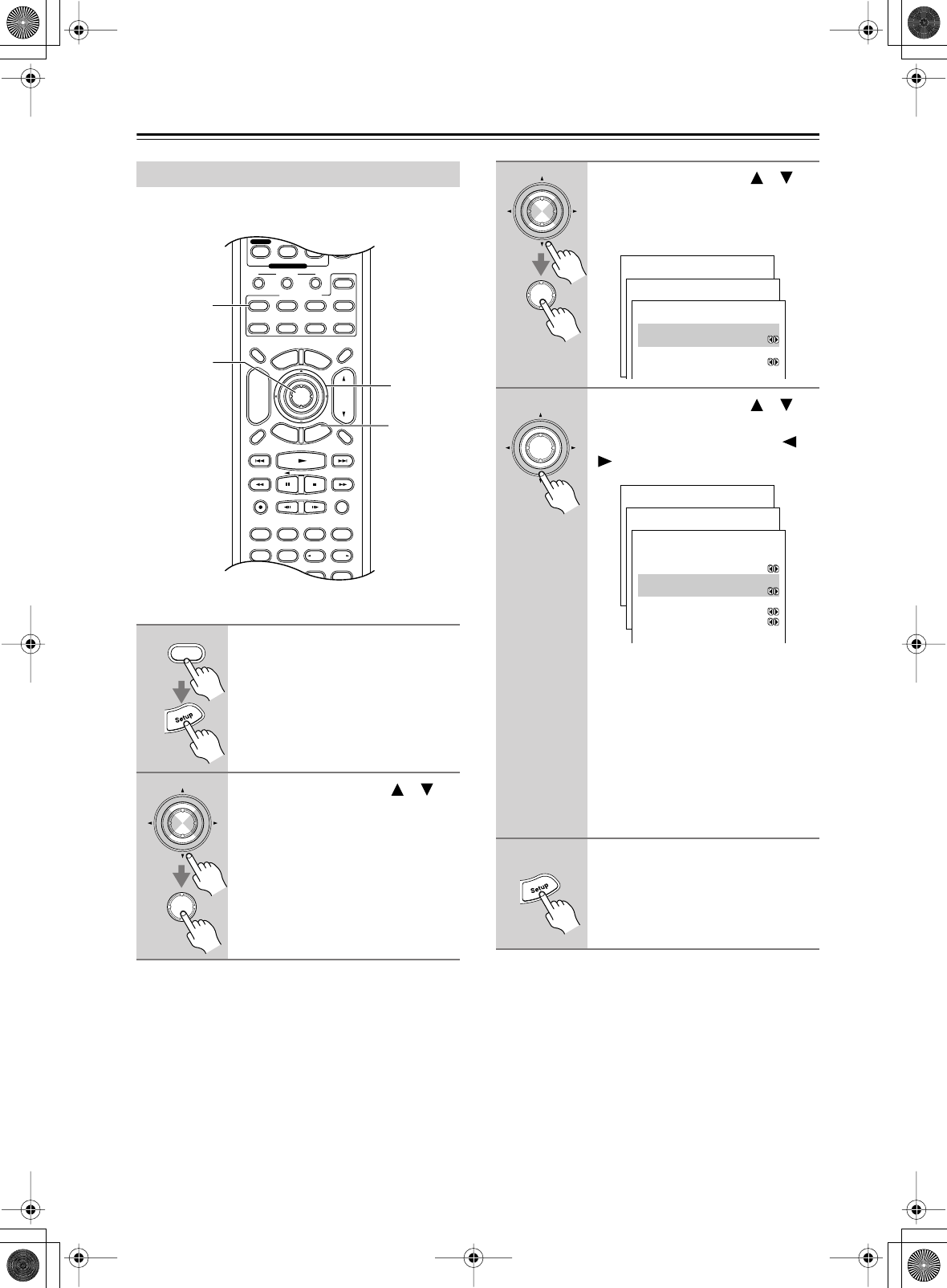
76
Zone 2
—Continued
The ZONE 2 OUT L/R jacks can also be used as pre
outs.
Setting the Zone 2 Out
1
Press the [Receiver] button fol-
lowed by the [Setup] button.
The main menu appears onscreen.
2
Use the Up and Down [ ]/[ ]
buttons to select “1. Initial
Setup,” and then press [Enter].
The Initial Setup menu appears.
Pure A
Display Muting
RandomRec
Last Memory
AngleSubtitleAudio
MemorySearchA-BRepeat
E
x
i
t
G
u
i
d
e
Prev
CH
TV VOL
--
/
---
Dimmer
Tape
TV
Input
Sleep
Enter
Test Tone
CH SEL
Surround
THX
Direct
StereoAll ST
Level+
Level-
LNi ht
DSP DSP
T
o
p
M
e
n
u
M
e
n
u
S
e
t
u
p
R
e
t
u
r
n
VOL
CH
Disc
SATTV VCR Cable
DVD
Receiver
CD
+10 0 Clear
789
Video OffOpen/Close
Macro
123
MD/CDR
Re EQ
+
-
Input Selector
Phono
Remote Mode
Zone 2
2–4
2, 3
1, 5
1
Receiver
Enter
Enter
3
Use the Up and Down [ ]/[ ]
buttons to select “3. Hardware
Setup,” and then press [Enter].
The Hardware Setup menu appears.
4
Use the Up and Down [ ]/[ ]
buttons to select “b. Zone 2 Out,”
and use the Left and Right [ ]/
[] buttons to select:
Fixed:
The ZONE 2 OUT L/R jacks
work as line outs, and you can control
the volume solely on the connected
amplifier.
Variable:
The ZONE 2 OUT L/R jacks
work as pre outs. Since the output level
is controlled by the AV receiver’s Mas-
ter Volume control, you cannot control
the volume solely on the connected
amplifier.
5
Press the [Setup] button.
The setup menu closes.
Enter
Enter
Menu
------------------------
1.Initial Setup
2.Speaker Setup
Advanced Setup
3.Surround Setup
4.Audio Adjust
5.Listening Mode Preset
6.Preference
Basic Setup
1.Initial Setup
------------------------
2.Component Video
3.Hardware Setup
1.Digital Input
1-3.Hardware Setup
------------------------
:Not Activated
b.Zone2 Out
:Fixed
a.Powered Zone2
Enter
Menu
------------------------
1.Initial Setup
2.Speaker Setup
Advanced Setup
3.Surround Setup
4.Audio Adjust
5.Listening Mode Preset
6.Preference
Basic Setup
1.Initial Setup
------------------------
2.Component Video
3.Hardware Setup
1.Digital Input
1-3.Hardware Setup
------------------------
:Not Activated
b.Zone2 Out
:Fixed
c.Sp Impedance Minimum
:6ohms
d.TV Format :AUTO
a.Powered Zone2
DTR-6.5,5.5_En.book Page 76 Wednesday, July 28, 2004 9:07 AM
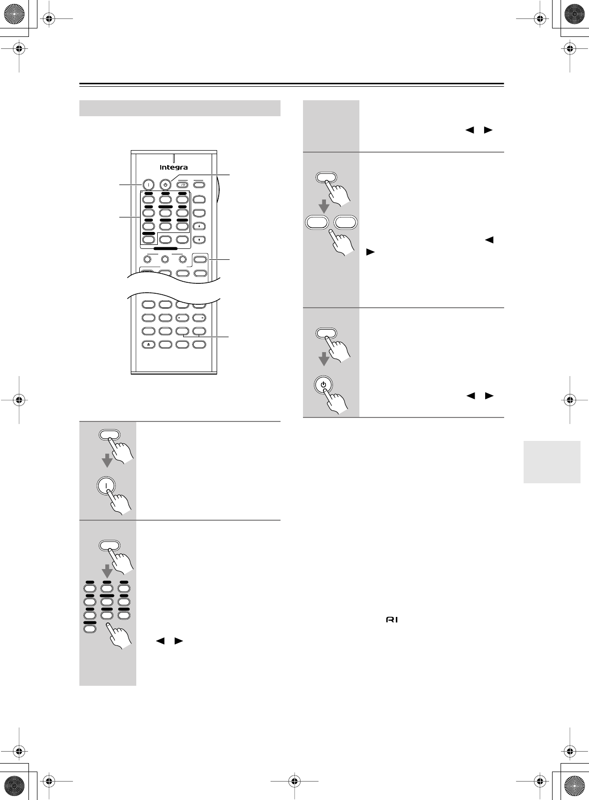
77
Zone 2
—Continued
Here you can turn on Zone 2, select an input source, and
adjust the volume.
Note:
To control Zone 2 with the remote controller, you must
press the [ZONE 2] button first.
Notes:
• If the Sleep function has been set, the Zone 2 compo-
nent will turn off along with the AV receiver when the
specified sleep time expires. To use the Sleep function
with Zone 2 only, set the Sleep function and then set
the AV receiver to Standby.
• Only analog input sources are output by the ZONE 2
LINE OUT and ZONE 2 SPEAKERS terminals. Dig-
ital input sources are not output. If no sound is heard
when an input source is selected, check if it’s con-
nected to an analog input.
• Since the Zone 2 function and the REC OUT outputs
use the same circuitry, if the [Rec Out] function is
used, Zone 2 will be turned off.
•While Zone 2 is being used, listening modes that need
surround back speakers (i.e., Dolby Digital EX, DTS-
ES, and THX Surround EX) are unavailable.
• While Zone 2 is on, functions will not work.
•You can’t select different radio stations for Zone 2 and
the main room. For example, if you an FM station for
the main room, that station will also be used in Zone 2.
Using Zone 2
1
Point the remote controller at the
AV receiver and press the
[ZONE 2] button followed by the
[On] button.
This turns on Zone 2 and the AV
receiver’s 12V TRIGGER OUT.
2
To select the Zone 2 input source
with the remote controller, press
the [ZONE 2] button followed by
an input selector button.
If you select AM or FM, you can use
the remote controller’s [TUNER] but-
ton to select the band.
To perform steps 1 and 2 on the
AV receiver, press the [ZONE 2]
button, and then use the Control-
ler [ ]/[ ] buttons within five
seconds.
The name of the selected Zone 2 source
appears on the display.
Pure A
On Standby TV
Last Memory
AngleSubtitleAudio
MemorySearchA-BRepeat
RC-585M
TV CH
TV VOL
--
/
---
Tape
Input
I
Test Tone
CH SEL
Surround
THX
Direct
StereoAll ST
Level+
Level-
L Night
DSP DSP
SATTV VCR Cable
DVD
Receiver
CD
+10 0 Clear
123
456
789
+
-
Video OffOpen/Close
Macro
123
MD/CDR
Re-EQ
Input Selector
V1V2V3
CD
Phono
Tape
V4DVD
Multi CH
Tuner
Remote Mode
Zone 2
3
1–4
4
2
1
Zone 2
On
Zone 2
V1V2V3
CD
Phono
Tap e
V4DVD
Multi CH
Tuner
To set Zone 2 to the same source as the
main room, press the [ZONE 2] button,
and then use the Controller [ ]/[ ]
buttons to select “Zone 2 Sel: Source.”
3
To adjust the Zone 2 volume with
the remote controller, press the
[ZONE 2] button, and then use
the [Level–] and [Level+] buttons.
To do this on the AV receiver,
press the Zone 2 [Level] button,
and then use the Controller [ ]/
[] buttons.
If the Zone 2 receiver/integrated amp is
connected to the AV receiver’s ZONE 2
LINE OUT L/R jacks, use the volume
control on the receiver/integrated amp.
4
To turn off Zone 2 with the
remote controller, press the
[ZONE 2] button followed by the
[Standby] button.
To do this from the AV receiver,
press the [ZONE 2] button, and
then use the Controller [ ]/[ ]
buttons to select OFF.
Zone 2
Level+
Level-
Zone 2
Standby
DTR-6.5,5.5_En.book Page 77 Wednesday, July 28, 2004 9:07 AM
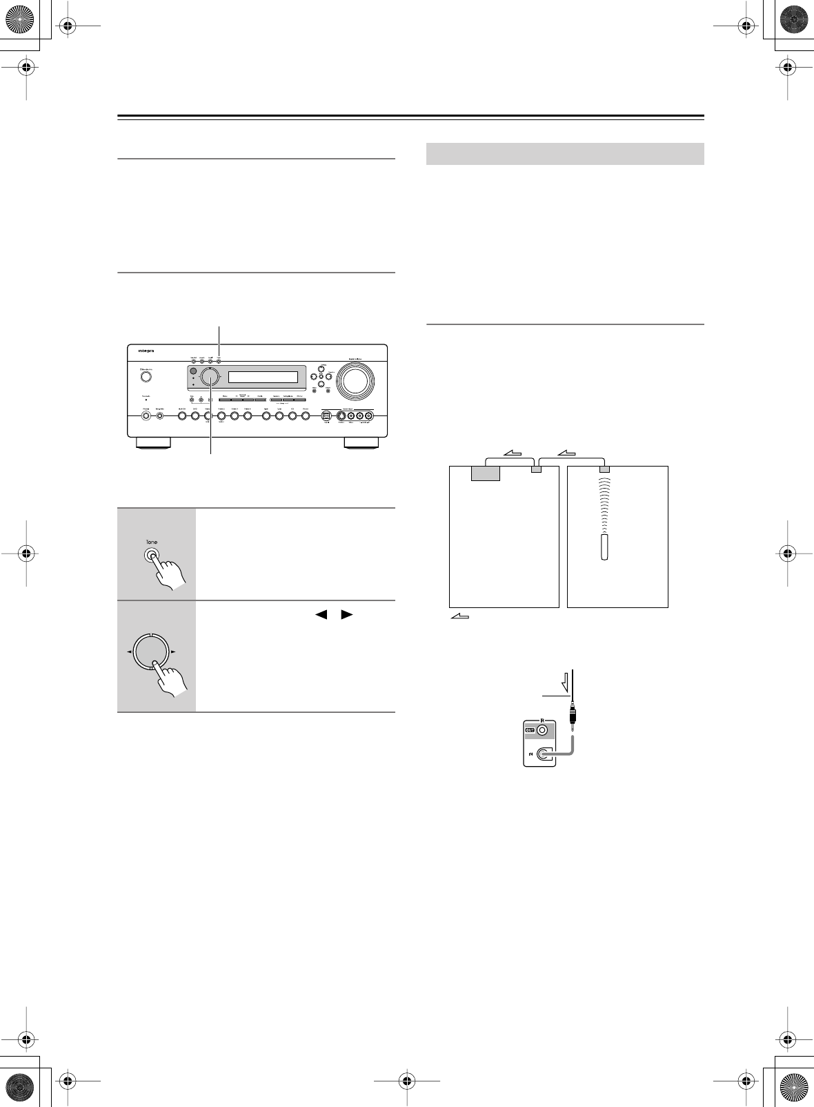
78
Zone 2
—Continued
Using the 12V Trigger
When the AV receiver’s 12 V TRIGGER OUT A/B/C
jack is connected to the 12 V TRIGGER IN jack on a
connected component, the AV receiver can be configured
so that the component is turned on automatically when
Zone 2 is used. See page 73 for details.
Adjusting the Bass & Treble for Zone2
You can adjust the bass and treble for Zone2.
■
Bass
You can boost or cut low-frequency sounds output by the
front speakers from –10 dB to +10 dB in 2 dB steps.
■
Treble
You can boost or cut high-frequency sounds output by
the front speakers from –10 dB to +10 dB in 2 dB steps.
To use the remote controller to control the AV receiver
from Zone 2, you’ll need one of the following commer-
cially available multiroom remote control kits:
•Multiroom Kits such as those made by Niles and Xan-
tech.
These kits can also be used when the AV receiver is not
in line of sight of the remote controller, for example,
when it’s installed inside a cabinet.
Using a Multiroom Kit with Zone 2
In the following diagram, an IR receiver picks up the
infrared signals from the remote controller in Zone 2 and
feeds them to the AV receiver in the main room via the
connecting block.
•On the Remote Setup menu, set the IR IN Position set-
ting to “Zone 2” (see page 72).
Connect the miniplug cable from the connecting block to
the AV receiver’s IR IN jack as shown below.
1
Press the [Tone] button repeat-
edly to select either Bass or
Treble.
2
Use the Controller [ ]/[ ] but-
tons to adjust.
Standby
Zone 2
1
2
Using the Remote Control in Zone 2
Connecting
block
Remote controller
IR Receiver
Main room Zone 2
Signal flow
from the connecting block
Miniplug cable
DTR-6.5,5.5_En.book Page 78 Wednesday, July 28, 2004 9:07 AM
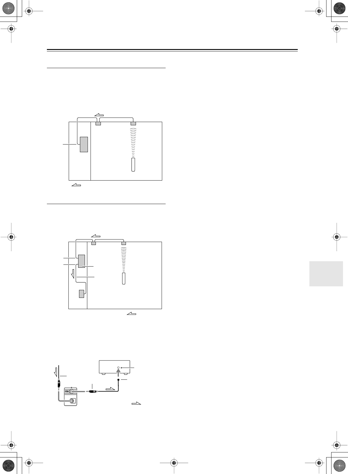
79
Zone 2
—Continued
Using a Multiroom Kit with a Cabinet
In the following diagram, an IR receiver picks up the
infrared signals from the remote controller and feeds
them to the AV receiver in the cabinet via the connecting
block.
•On the Remote Setup menu, set the IR IN Position set-
ting to “Main” (see page 72).
Controlling Out-of-range Components
If another AV component is out of range of its remote
controller, you can use a commercially available IR
emitter to retransmit the remote controller signals
received at the AV receiver’s IR IN, as shown below.
Connect the IR emitter to the AV receiver’s IR OUT, and
place the IR emitter in front of the other AV component’s
remote control sensor (usually located on the front
panel), as shown below. See the instructions supplied
with the IR emitter.
Only remote controller signals received by the AV
receiver’s IR IN are fed through to the IR OUT. Signals
picked up by the AV receiver’s remote control sensor are
not output.
IR IN
Connecting
block
Remote controller
IR Receiver
Inside
cabinet
Signal flow
IR IN
IR OUT
Signal flow
Remote controller
IR Receiver
Connecting
block
IR Emitter
DTR-6.5/5.5
Other
component
Signal flow
Remote control
sensor
Emitter
IR Emitter
from connecting block
Miniplug cable
Other component
Mini plug
DTR-6.5/5.5
DTR-6.5,5.5_En.book Page 79 Wednesday, July 28, 2004 9:07 AM
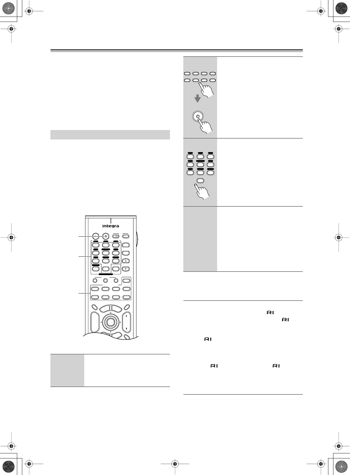
80
Controlling Other Components
You can use the AV Receiver’s remote controller (RC-
588M/RC-590M/RC-591M) to control your other com-
ponents, including those made by other manufacturers.
This chapter explains how to:
• Enter the remote control code for a component that
you want to control (e.g., DVD, TV, VCR).
• Learn commands directly from another component’s
remote controller (see page 88).
•Program the Macro function to perform a sequence of
actions with a single press of a button (see page 89).
Entering the appropriate remote control code for each
Remote Mode button will allow you to control your
other components with the remote controller. You’ll need
to perform this procedure for each component that you
want to control.
For the [DVD], [TV], [VCR], [CABLE], and [SAT] but-
tons, choose a code from the respective category. For the
[CD] and [MD/CDR] buttons, you can choose a code
from any category. Remote control codes cannot be
entered for the [Receiver] and [ZONE 2] buttons.
If the remote controller works OK, the code has been
entered correctly. If not, try again or try another code.
Codes for Integra DVD Players
The remote control code for an Integra DVD player
depends on whether it’s connected via , as follows:
5001:
Use this code if you’ve connected an cable
and an analog audio cable to your DVD player.
This is the default setting, so if you’re using
, you don’t need to change anything. Point
the remote controller at the AV receiver to
operate the DVD player.
5002:
Use this code if your DVD player doesn’t have
an jack, or you’re not using . Point the
remote controller at the DVD player to operate
it.
Setting the [MD/CDR] Button to CDR
By default, the [MD/CDR] button is set to control a
MiniDisc recorder. To control a CD recorder, it must be
set to CDR. The codes are as follows:
6002:
Code for controlling an CD recorder.
6003:
Code for controlling an MD recorder (default).
Entering Remote Control Codes
1
Look up the remote control code
for your component.
See “Remote Control Codes” on
page 82.
On Standby TV
Display Muting
E
x
i
t
G
u
i
d
e
Prev
CH
TV CH
TV VOL
--
/
---
Dimmer
Tape
TV
Input
Sleep
Input
I
Enter
T
o
p
M
e
n
u
M
e
n
u
S
e
t
u
p
R
e
t
u
r
n
VOL
CH
Disc
SATTV VCR Cable
DVD
Receiver
CD
+10 0 Clear
123
456
789
+
-
Macro
123
MD/CDR
+
-
Input Selector
V1V2V3
CD
Phono
Tape
V4DVD
Multi CH
Tuner
Remote Mode
Zone 2
2
2
3
2
While holding down the Remote
Mode button that you want to
enter the code for, press the
[Standby] button.
3
Within 30 seconds, use the num-
ber buttons to enter the 4-digit
remote control code.
4
Select the remote controller
mode, point the remote control-
ler at the component, and check
its operation.
Remote controller buttons that can be
used in DVD mode are shown on
page 16. Those that can be used with
the TV, VCR, CABLE, and SAT modes
are shown on pages 86, 87.
Standby
Tape
SATTV VCR Cable
DVD
Receiver
CD
MD/CDR
Remote Mode
0
123
456
789
V1V2V3
CD Tape
V4DVD
Multi CH
Tuner
DTR-6.5,5.5_En.book Page 80 Wednesday, July 28, 2004 9:07 AM
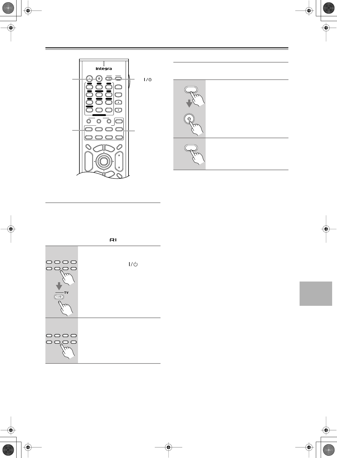
81
Controlling Other Components
—Continued
Resetting Remote Mode Buttons
If you’ve entered another code for one of these button
and now want to return to the default, perform the fol-
lowing procedure.
By default, some REMOTE MODE buttons are prepro-
grammed with remote control codes for controlling Inte-
gra components connected via .
Resetting the Remote Controller
Here you can reset the remote controller to its default
settings.
1
While holding down the Remote
Mode button that you want to
reset, press the TV [ ] button.
Release both buttons and wait two sec-
onds.
2
Press the Remote Mode button
again.
The Remote Mode button is reset.
On Standby TV
Display Muting
E
x
i
t
G
u
i
d
e
Prev
CH
TV CH
TV VOL
--
/
---
Dimmer
Tape
TV
Input
Sleep
Input
I
Enter
T
o
p
M
e
n
u
M
e
n
u
S
e
t
u
p
R
e
t
u
r
n
VOL
CH
Disc
SATTV VCR Cable
DVD
Receiver
CD
+10 0 Clear
123
456
789
+
-
Macro
123
MD/CDR
+
-
Input Selector
V1V2V3
CD
Phono
Tape
V4DVD
Multi CH
Tuner
Remote Mode
Zone 2
Standby
Remote
Mode
TV
Receiver
Tape
SATTV VCR Cable
DVD
Receiver
CD
MD/CDR
Remote Mode
Tape
SATTV VCR Cable
DVD
Receiver
CD
MD/CDR
Remote Mode
1
While holding down the
[Receiver] button, press the
[Standby] button.
Release both buttons and wait five sec-
onds.
2
Press the [Receiver] button
again.
The remote controller is reset.
Receiver
Standby
Receiver
DTR-6.5,5.5_En.book Page 81 Wednesday, July 28, 2004 9:07 AM
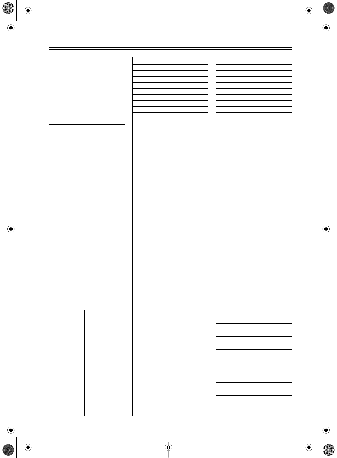
82
Controlling Other Components
—Continued
Remote Control Codes
When two or more codes are given,
try each one in turn, and choose the
one that works best.
Depending on the manufacturer and
component, the remote controller
may not work as expected.
DVD (DVD player)
Manufacturer Control code
Aiwa 5010
Akai 5019
Apex 5015, 5016
CyberHome 5027
Denon 5017, 5020
GE 5003
Hitachi 5009
Integra 5001, 5002
Integra Research 5001, 5002
JVC 5023
Kenwood 5017
Magnavox 5004, 5021
Marantz 5025, 5026
Mitsubishi 5005
Onkyo 5001, 5002
Panasonic 5011, 5017, 5020
Philips 5004, 5021, 5028
Pioneer 5006
Proscan 5003
RCA 5003
Sanyo 5012
Sony 5007, 5013, 5018,
5029
Technics 5020
Thomson 5022, 5024
Toshiba 5008, 5021
Xbox 5022
Yamaha 5020
Zenith 5014, 5021
SAT (satellite receiver)
Manufacturer Control code
Alba 4014, 4017, 4025, 4027
Allsat 4015, 4027
Alltech 4022, 4025
Amstrad 4013, 4019, 4025, 4030,
4031
Anglo 4025
Ankaro 4025
Anttron 4017
Apollo 4017
Arcon 4016
Armstrong 4013
Asat 4016
Astra 4013, 4016, 4024
Astro 4019, 4020
AudioTon 4015
Bush 4012, 4014
Condor 4024
Conrad 4024
Cosat 4015, 4023
Crown 4013
Daewoo 4016, 4017, 4025
Diamond 4022
Dishnet 4008
Dual 4016
Echostar 4010, 4018, 4025
Einhell 4013, 4017, 4025
Elta 4015, 4017
Engel 4025
Eurosat 4013, 4022
Eurosky 4013, 4024
Eurostar 4024
Fagor 4015, 4023
Ferguson 4012
Fidelity 4030
Fracarro 4017
FTE 4025, 4030
Fuba 4017
Galaxis 4015, 4023
GE 4001, 4002
General Instruments 4003
GMI 4013
Grundig 4021, 4029, 4031
Hinari 4017
Hirschmann 4019, 4035
Hitachi 4036, 4037
Hughes Network
Systems 4011
Huth 4013, 4015, 4024
Imperial 4014
Intertronic 4013
Intervision 4015, 4023, 4024
Johansson 4015
JVC 4009, 4021
Kathrein 4025
Kolon 4017
K-SAT 4025
Kyostar 4017
Lasat 4013, 4020, 4024
Lenco 4016, 4017, 4025
Lennox 4023
Loewe 4013
Lorenzen 4024
Macab 4022
Manhattan 4015, 4020, 4023
Maspro 4021, 4025
Matsui 4021
Mediamarkt 4013
Medion 4025
Metronic 4013, 4017, 4020
Micro Technology 4025
Minerva 4021
Morgan’s 4013, 4015, 4025
Mysat 4025
Neuhaus 4019, 4023, 4024, 4025
Neusat 4025
SAT (satellite receiver)
Manufacturer Control code
Nikko 4013, 4025, 4027
Nokia 4033
Nordmende 4017, 4020
Oceanic 4022
Octagon 4016, 4017
Okano 4013
Optex 4015, 4023
Orbit 4016
Orbitech 4017, 4019
Pace 4012, 4026, 4031
Pacific 4022
Palladium 4013, 4017, 4021
Palsat 4019
Panasonic 4006, 4031
Panda 4024
Philips 4021, 4029
Phonotrend 4015, 4023
Predki 4017
Premier 4023
Primestar 4007
Proscan 4001, 4002
Protek 4022
Pye 4021
Quelle 4024
Radix 4035
RCA 4001, 4002
Roadster 4025
Rover 4025
Saba 4014, 4020, 4024, 4027
Samsung 4017
Satcom 4024
SatPartner 4017, 4020, 4027, 4030
Schneider 4029
Sedea Electronique 4017
Seemann 4013
SEG 4017, 4028
Seleco 4015, 4023
Skymaster 4025, 4034
Skyvision 4015
Sony 4005, 4031
Strong
4016, 4017, 4020
Sunstar
4013
Techniland
4015, 4023
TechniSat
4019
Teco
4013, 4016
Teleciel
4027
Telefunken
4017
Teleka
4013
Telemaster
4020
Telewire
4015, 4023
Tensai
4016
Thomson
4024, 4025
Thorens
4022
Tonna
4015, 4023, 4025
Toshiba
4004
Tr iasat
4019
SAT (satellite receiver)
Manufacturer Control code
DTR-6.5,5.5_En.book Page 82 Wednesday, July 28, 2004 9:07 AM
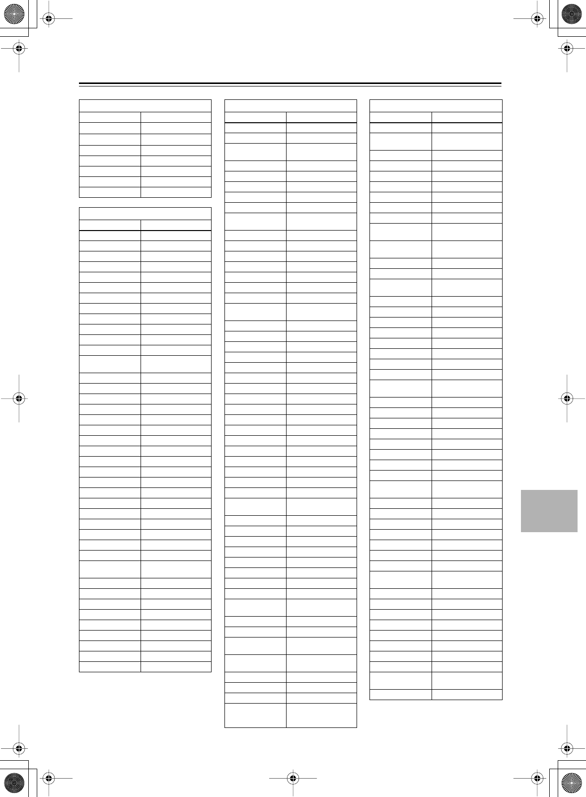
83
Controlling Other Components
—Continued
SAT (satellite receiver)
Manufacturer Control code
Tr istar
4016
Unisat
4013
Universum 4021, 4024
Vo r tec 4017
Wela 4025
Zehnder 4020
Zenith 4032
CBL (cable receiver)
Manufacturer Control code
ABC 3001, 3002, 3021
Archer 3006
Cabletime 3028, 3032
Cableview 3004
Contec 3009
Eastern 3010
GE 3001, 3002
Gemini 3011
General Instruments 3002, 3022
Grundig 3031
Hamlin 3012
Hitachi 3002
Jerrold 3002, 3011, 3013, 3021,
3022, 3023, 3026
Magnavox 3014
Memorex 3015
Movie Time 3016
NEC 3003
Nokia 3033
NSC 3016
Oak 3009
Panasonic 3020
Philips 3007, 3008, 3014
Pioneer 3017, 3024
Proscan 3001, 3002
RCA 3004, 3020, 3022
Realistic 3006
Sagem 3034
Salora 3029
Samsung 3017
Signature 3002
Sprucer 3020
Standard
Component 3018
Starcom 3011, 3021
Stargate 3011
Tele+1 3030
Tocom 3013
United Cable 3021, 3023
Universal 3005, 3006
Videoway 3025
View Star 3009, 3014, 3016
Zenith 3019
VCR
Manufacturer Control code
Aiwa 2012, 2046, 2047
Akai 2003, 2004, 2022
Alba 2033, 2041, 2044, 2045,
2047
Anitech 2033
ASA 2034
Baird 2036
Bell & Howell 2007
Blaupunkt 2039, 2042
Bush 2033, 2041, 2044, 2045,
2047
Canon 2010, 2011
Carver 2014
Cimline 2033
Citizen 2008, 2009
Colortyme 2005
Craig 2008
Crown 2033
Curtis Mathes 2001, 2005, 2008, 2009,
2010, 2011, 2023, 2026
Cyrus 2034
Daewoo 2012
Dansai 2033
Decca 2034
Dimensia 2001, 2026
Dumont 2034, 2036, 2037
Elcatech 2033
Emerson 2003, 2010, 2012, 2022
ESC 2043
Ferguson 2035
Finlandia 2034, 2036
Finlux 2034, 2036, 2037
Firstline 2033, 2041
Fisher 2007, 2030, 2036
Fuji 2004, 2010, 2024
Funai 2012
Garrard 2012
GE 2001, 2002, 2008, 2010,
2011, 2023, 2025, 2026
GEC 2034
GoldHand 2033
GoldStar 2005, 2009
Goodmans 2031, 2033
Gradiente 2012
Graetz 2036, 2043
Granada 2030, 2034, 2036
Grandin 2033
Grundig 2029, 2033, 2034, 2039,
2040, 2042, 2044
Harman Kardon 2005
HCM 2033, 2044
Hinari 2028, 2033, 2043, 2044,
2047
Hitachi 2013, 2021, 2025, 2028,
2037, 2038, 2043
Ingersol 2028
Interfunk 2034
ITT 2030, 2036, 2043, 2048
JC Penney
2005, 2006, 2007, 2008,
2010, 2011, 2013, 2014,
2021
Jensen 2013
JVC 2005, 2006, 2007, 2009,
2032, 2035, 2040, 2048
Kaisui 2033
Kendo 2041, 2046
Kenwood 2005, 2006, 2007, 2009
Kodak 2010
Loewe 2028, 2034
Logik 2028, 2043
Luxor 2030, 2031, 2036
Magnavox 2010, 2011, 2014, 2019,
2020
Marantz 2005, 2006, 2007, 2009,
2010, 2014, 2031, 2034
Matsui 2028, 2041, 2046, 2047
Matsushita 2010
Memorex 2007, 2008, 2010, 2012,
2019, 2030, 2036
Metz 2039
MGA 2022
Minerva 2039
Minolta 2013, 2021
Mitsubishi 2013, 2022, 2032, 2034
Motorola 2010
MTC 2008
Multitech 2008, 2012, 2033
NEC 2005, 2006, 2007, 2009,
2032
Neckermann 2034
Nesco 2033
NOBLEX 2008
Nokia 2030, 2036, 2043
Nordmende 2048
Okano 2046
Olympus 2010
Optonica 2017
Orion 2028, 2041, 2045, 2046,
2047
Osaki 2033
Otto Versand 2034
Palladium 2033
Panasonic 2010, 2011, 2042
Pentax 2013, 2021, 2025, 2037
Pentex Research 2009
Philco 2010, 2011, 2014
Philips 2010, 2014, 2017, 2034,
2048
Phonola 2034
Pioneer 2006, 2013, 2032, 2034
Proline 2044
Proscan 2001, 2002, 2026
Pye 2034
Quasar 2010, 2011
Quelle 2034
Radio Shack 2017
Radio Shack/
Realistic
2007, 2008, 2010, 2011,
2012, 2017
Radiola 2034
VCR
Manufacturer Control code
DTR-6.5,5.5_En.book Page 83 Wednesday, July 28, 2004 9:07 AM
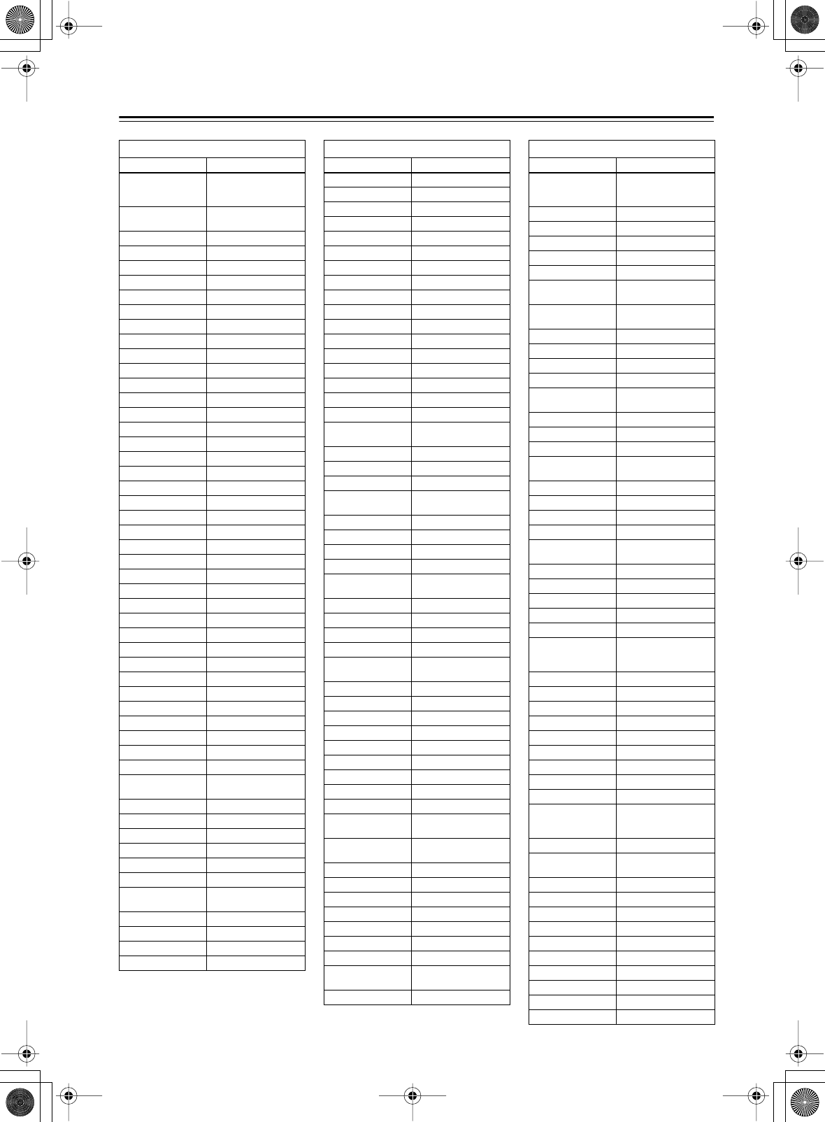
84
Controlling Other Components
—Continued
VCR
Manufacturer Control code
RCA
2001, 2002, 2003, 2008,
2010, 2013, 2021, 2023,
2025, 2026, 2027
Realistic 2007, 2008, 2010, 2011,
2012, 2017
Rex 2048
Roadstar 2033, 2043
Runco 2019
Saba 2040, 2048
Saisho 2028, 2041
Salora 2030
Samsung 2008, 2043, 2049
Sansui 2006, 2032
Sanyo 2007, 2008, 2030, 2036
Saville 2047
SBR 2034
Schaub Lorenz 2036
Schneider 2033, 2034
Scott 2015
Sears 2007, 2010, 2013, 2021
SEG 2043
SEI 2028, 2034
Sharp 2016, 2017, 2031
Shintom 2004, 2033, 2036
Shorai 2028
Siemens 2034, 2036, 2039
Singer 2010
Sinudyne 2028, 2034
Sonolor 2030, 2031
Sony 2004, 2018, 2024
STS 2010, 2021
Sunkai 2046
Sylvania 2010, 2011, 2012, 2014
Symphonic 2012
Tandy 2007
Tatung 2034
Teac 2012
Technics 2010, 2042
Teknika 2010, 2012
Telefunken 2048
Thomson 2048
Thorn 2035, 2036
Toshiba 2013, 2015, 2022, 2034,
2048
Totevision 2008
Uher 2043
Unitech 2008
Universum 2034, 2039, 2043
Vector Research 2005, 2006
Video Concepts 2005, 2006, 2022
Wards 2008, 2010, 2012, 2013,
2017, 2021, 2027
XR-1000 2010, 2012
Yamaha 2005, 2006, 2007, 2009
Yo ko 2043
Zenith 2004, 2019, 2024
TV
Manufacturer Control code
Admiral 1026, 1040, 1062
Akai 1002, 1067
Akura 1045
Alba 1035, 1043
Amplivision 1063
Amstrad 1035, 1067
Amtron 1009
Anam National 1003, 1009
Anitech 1035
AOC 1004, 1005, 1006
Arc en Ciel 1066
Arcam 1063
ASA 1040
Audiovox 1009
Autovox 1040, 1068
Baird 1069
Bang & Olufsen 1040
Baur 1036, 1054, 1055, 1058,
1059, 1068
Beko 1052
Bell & Howell 1010, 1017
Binatone 1063
Blaupunkt 1041, 1042, 1044, 1058,
1059
Boots 1063
Brionvega 1040
Bruns 1040
BSR 1048
Bush 1035, 1043, 1048, 1050,
1053, 1057
Cascade 1035
Celebrity 1002
Century 1040
Cimline 1035, 1043
Citizen 1004, 1006, 1009, 1017,
1022, 1025
Clatronic 1052
Colortyme 1004, 1006
Condor 1052
Contec 1035
Contec/Cony 1007, 1009
Continental Edison 1066
Craig 1009
Crosley 1040
Crown 1009, 1014, 1035, 1052
Curtis Mathes 1001, 1004, 1006, 1010,
1017, 1022, 1025, 1034
Daewoo 1004, 1005, 1006, 1025,
1035, 1053
Daytron 1004, 1006, 1025, 1035
Decca 1067
Dimensia 1001, 1034
Dixi 1035
Dual 1057, 1068
Dumont 1004, 1039, 1040
Electroband 1002
Electrohome 1002, 1003, 1004, 1006,
1008
Elta 1035
Emerson
1004, 1006, 1007, 1009,
1010, 1017, 1025, 1027,
1029, 1033, 1040, 1070
Envision 1004, 1006
Erres 1037
Europhon 1067
Fidelity 1068
Finlux 1039, 1040, 1067
Firstline 1035, 1043, 1048, 1049,
1063
Fisher 1010, 1017, 1052, 1063,
1068
Formenti 1040
Frontech 1045, 1062
Fujitsu 1070
Funai 1009, 1045, 1048, 1070
GE 1001, 1003, 1004, 1006,
1011, 1012, 1019, 1034
GEC 1038, 1063, 1067, 1069
Geloso 1035
Genexxa 1062
GoldStar 1004, 1005, 1006, 1007,
1008, 1025, 1047, 1063
Goodmans 1043, 1053, 1063
Gorenje 1052
Graetz 1062, 1069
Granada 1063, 1067
Grundig 1039, 1041, 1042, 1058,
1059, 1064
Hallmark 1004, 1006
Hanseatic 1060, 1068
Hantarex 1067
HCM 1035
Hinari 1035, 1043
Hitachi
1004, 1006, 1007, 1013,
1027, 1038, 1062, 1063,
1069
Huanyu 1053
ICE 1045, 1063
Imperial 1052
Infinity 1014
Inno Hit 1056, 1067
Interfunk 1055, 1062, 1066, 1069
Intervision 1045, 1063
ITT 1062, 1068, 1069
JBL 1014
JC Penney
1001, 1004, 1005, 1006,
1011, 1012, 1016, 1019,
1022, 1025, 1034
Jensen 1004, 1006
JVC 1007, 1012, 1013, 1015,
1033
Kaisui 1035, 1063
Kapsch 1062, 1069
Kathrein 1060
Kawasho 1002, 1004, 1006
Kendo 1043
Kenwood 1004, 1006, 1008
Kloss Novabeam 1009
Kor ting 1040
KTV 1009, 1025
LG 1005
TV
Manufacturer Control code
DTR-6.5,5.5_En.book Page 84 Wednesday, July 28, 2004 9:07 AM
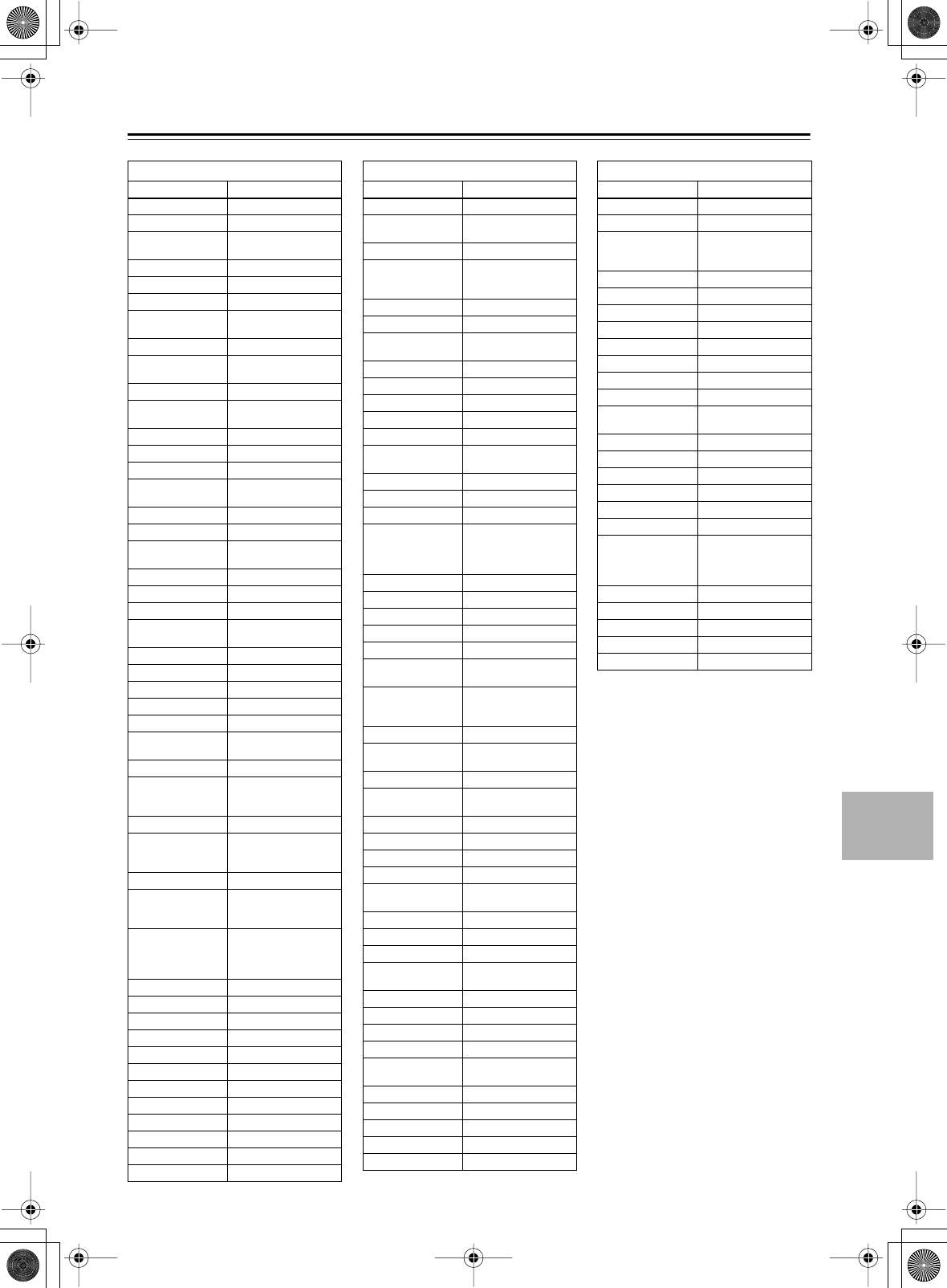
85
Controlling Other Components
—Continued
TV
Manufacturer Control code
Loewe 1014, 1040, 1055
Luxman 1004, 1006
LXI 1001, 1006, 1010, 1014,
1016, 1017, 1034
M Electronic 1035, 1053, 1062, 1063
Magnadyne 1040, 1067, 1068
Magnafon 1067
Magnavox 1004, 1006, 1008, 1014,
1018, 1020
Marantz 1004, 1006, 1014, 1060
Matsui 1035, 1043, 1048, 1050,
1063, 1064, 1067, 1068
Megatron 1006
Memorex 1005, 1006, 1010, 1017,
1035
Metz 1040, 1051, 1058
MGA 1004, 1005, 1006, 1008
Minerva 1039, 1058, 1059, 1064
Mitsubishi 1004, 1005, 1006, 1008,
1040, 1055, 1058
Mivar 1047, 1056, 1067
Motorola 1003, 1026
MTC 1004, 1005, 1006, 1022,
1055
Multitech 1009, 1035
NAD 1006, 1016
NEC 1003, 1004, 1005, 1006
Neckermann 1040, 1041, 1054, 1059,
1060
Nikkai 1045
Nikko 1006
Oceanic 1062
Onwa 1009
Optonica 1021, 1026
Orion 1029, 1043, 1048, 1049,
1050, 1067, 1068
Osaki 1045, 1063
Otto Versand
1036, 1041, 1043, 1054,
1055, 1058, 1059, 1060,
1063
Palladium 1052
Panasonic
1003, 1012, 1014, 1031,
1044, 1046, 1051, 1061,
1062, 1069
Pathe Marconi 1066
Philco
1003, 1004, 1005, 1006,
1007, 1008, 1014, 1018,
1040
Philips
1003, 1004, 1007, 1008,
1014, 1018, 1019, 1020,
1037, 1038, 1040, 1053,
1059, 1060
Phoenix 1040
Phonola 1037, 1040
Pioneer 1004, 1006, 1027, 1062
Portland 1004, 1005, 1006, 1025
Price Club 1022
Prism 1012
Profex 1035
Proline 1049
Proscan 1001, 1034
Protech 1035, 1045, 1063
Proton 1004, 1006, 1007
Pye 1037
Quasar 1003, 1012, 1031
Quelle 1036, 1039, 1054, 1055,
1058, 1059, 1068
Radio Shack 1010, 1017, 1034
Radio Shack/
Realistic
1001, 1004, 1006, 1007,
1009, 1010, 1017, 1021,
1025
Radiola 1037
Radiomarelli 1040, 1067
RCA 1001, 1003, 1004, 1005,
1006, 1008, 1027, 1034
Realistic 1010, 1017, 1034
Rex 1045, 1062
RFT 1040
Roadstar 1035, 1045
Saba 1040, 1062, 1066, 1069
Saisho 1035, 1043, 1045, 1067,
1068
Salora 1062
Sambers 1056, 1067
Sampo 1004, 1006, 1025
Samsung
1004, 1005, 1006, 1007,
1008, 1022, 1025, 1035,
1045, 1047, 1052, 1056,
1060, 1063, 1065
Sansui 1029
Sanyo 1004, 1010, 1017
SBR 1037, 1038
Schaub Lorenz 1069
Schneider 1068
Scott 1004, 1006, 1007, 1009,
1070
Sears
1001, 1004, 1006, 1008,
1010, 1015, 1016, 1017,
1028, 1034, 1070
SEG 1045, 1063
SEI 1036, 1040, 1048, 1067,
1068
Seleco 1062
Sharp 1004, 1006, 1007, 1021,
1023, 1025, 1026
Shorai 1048
Siarem 1040, 1067
Siemens 1041, 1042, 1058, 1059
Singer 1040
Sinudyne 1036, 1040, 1043, 1067,
1068
Solavox 1062
Sonoko 1035
Sonolor 1062
Sony 1002, 1030, 1032, 1036,
1054
Soundesign 1004, 1006, 1009, 1070
Starlite 1009
Stern 1062
Sunkai 1043, 1048, 1049, 1050
Sylvania 1004, 1006, 1008, 1014,
1018, 1020
Symphonic 1009, 1028
Tandy 1026, 1062, 1063
Tashiko 1038, 1063
Tatung 1003, 1063, 1067
Te c 1063
TV
Manufacturer Control code
Technics 1012, 1044, 1061
Techwood 1004, 1006, 1012
Teknika
1004, 1005, 1006, 1007,
1009, 1022, 1025, 1031,
1070
Teleavia 1066
Telecaption 1024
Telefunken 1066
Teletech 1035
Teleton 1063
Tensai 1048
Thomson 1066
Thorn 1054, 1055, 1058
Toshiba 1010, 1016, 1017, 1022,
1024, 1039
Totevision 1025
Tr iumph 1067
Universal 1011, 1019
Universum 1045, 1052, 1058
Voxson 1040, 1062
Waltham 1063
Wards
1001, 1004, 1005, 1006,
1008, 1011, 1014, 1018,
1019, 1020, 1021, 1034,
1070
Watt Radio 1068
Wega 1040
Yamaha 1004, 1005, 1006, 1008
Yo ko 1045, 1063
Zenith 1004
TV
Manufacturer Control code
DTR-6.5,5.5_En.book Page 85 Wednesday, July 28, 2004 9:07 AM
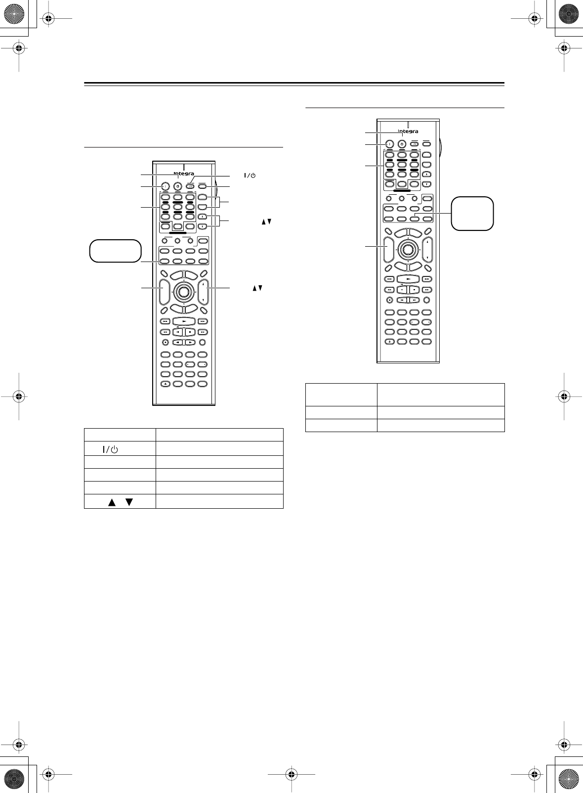
86
Controlling Other Components
—Continued
To control another component, point the remote control-
ler at it and use the buttons as explained below (you must
select the appropriate remote control mode first).
Controlling a TV
Buttons marked with an asterisk can always be used to
control a TV regardless of the currently selected remote
controller mode.
The following buttons control the AV Receiver.
[VOL]: Adjusts the volume of the AV receiver.
[Muting]: Mutes the AV Receiver.
Controlling a Cable Receiver
The following buttons control the AV Receiver.
[VOL]: Adjusts the volume of the AV receiver.
[Muting]: Mutes the AV Receiver.
[On], [Standby]
Set the TV to On or Standby
TV [ ]
Tu rn the TV on or off
Number buttons
Enter numbers
[CH +/–]
Select channels on the TV
[TV INPUT]
Select inputs on the TV
VOL [ ]/[ ]
Adjust the TV’s volume
Pure A
On Standby TV
Display Muting
RandomRec
Last Memory
AngleSubtitleAudio
MemorySearchA-BRepeat
RC-585M
E
x
i
t
G
u
i
d
e
Prev
CH
TV CH
TV VOL
--
/
---
Dimmer
Tape
TV
Input
Sleep
Input
I
Enter
Test Tone
CH SEL
Surround
THX
Direct
StereoAll ST
Level+
Level-
L Night
DSP DSP
T
o
p
M
e
n
u
M
e
n
u
S
e
t
u
p
R
e
t
u
r
n
VOL
CH
Disc
SATTV VCR Cable
DVD
Receiver
CD
+10 0 Clear
123
456
789
+
-
Video OffOpen/ Close
Macro
123
MD/CDR
Re-EQ
+
-
Input Selector
V1V2V3
CD
Phono
Tape
V4DVD
Multi CH
Tuner
Remote Mode
Zone 2
CH
TV Input
TV CH +/–
VOL
On
*
*
*
*
Standby
TV VOL
TV
Number
buttons
Press [TV]
first
*
[On], [Standby]
Set the cable receiver to On or
Standby
[CH +/–]
Select cable channels
Number buttons
Enter numbers
Pure A
On Standby TV
Display Muting
RandomRec
Last Memory
AngleSubtitleAudio
MemorySearchA-BRepeat
RC-585M
E
x
i
t
G
u
i
d
e
Prev
CH
TV CH
TV VOL
--
/
---
Dimmer
Tape
TV
Input
Sleep
Input
I
Enter
Test Tone
CH SEL
Surround
THX
Direct
StereoAll ST
Level+
Level-
L Night
DSP DSP
T
o
p
M
e
n
u
M
e
n
u
S
e
t
u
p
R
e
t
u
r
n
VOL
CH
Disc
SATTV VCR Cable
DVD
Receiver
CD
+10 0 Clear
123
456
789
+
-
Video OffOpen/ Close
Macro
123
MD/CDR
Re-EQ
+
-
Input Selector
V1V2V3
CD
Phono
Tape
V4DVD
Multi CH
Tuner
Remote Mode
Zone 2
CH
On
Standby
Number
buttons
Press
[CABLE]
first
DTR-6.5,5.5_En.book Page 86 Wednesday, July 28, 2004 9:07 AM
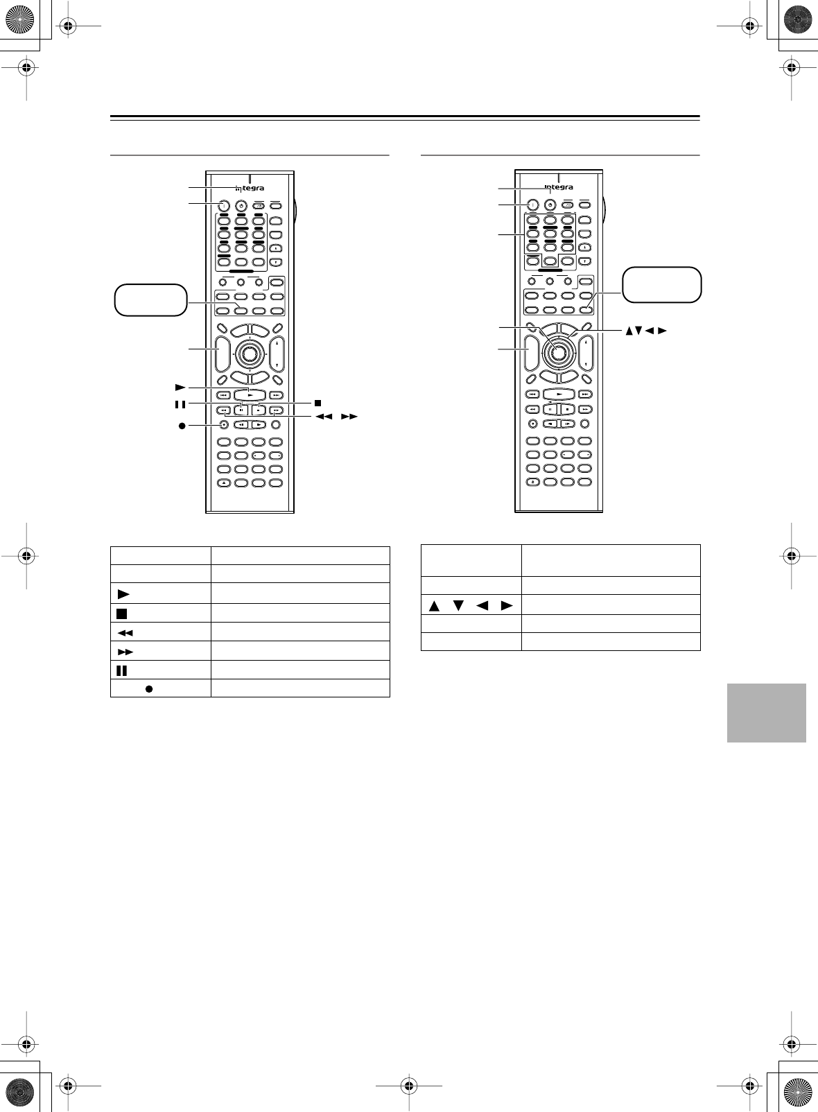
87
Controlling Other Components
—Continued
Controlling a VCR
The following buttons control the AV Receiver.
[VOL]: Adjusts the volume of the AV receiver.
[Muting]: Mutes the AV Receiver.
Controlling a Satellite Receiver
The following buttons control the AV Receiver.
[VOL]: Adjusts the volume of the AV receiver.
[Muting]: Mutes the AV Receiver.
[On], [Standby]
Set the VCR to On or Standby
[CH +/–]
Selects channels on the VCR
[]
Play
[]
Stop
[]
Rewind
[]
Fast forward
[]
Pause
REC [ ]
Record
Pure A
On Standby TV
Display Muting
RandomRec
Last Memory
AngleSubtitleAudio
MemorySearchA-BRepeat
RC-585M
E
x
i
t
G
u
i
d
e
Prev
CH
TV CH
TV VOL
--
/
---
Dimmer
Tape
TV
Input
Sleep
Input
I
Enter
Test Tone
CH SEL
Surround
THX
Direct
StereoAll ST
Level+
Level-
L Night
DSP DSP
T
o
p
M
e
n
u
M
e
n
u
S
e
t
u
p
R
e
t
u
r
n
VOL
CH
Disc
SATTV VCR Cable
DVD
Receiver
CD
+10 0 Clear
123
456
789
+
-
Video OffOpen/ Close
Macro
123
MD/CDR
Re-EQ
+
-
Input Selector
V1V2V3
CD
Phono
Tape
V4DVD
Multi CH
Tuner
Remote Mode
Zone 2
CH
Rec
On
Standby
,
Press
[VCR] first
[On], [Standby]
Set the satellite receiver to On or
Standby
[CH +/–]
Select satellite channels
[ ]/[ ]/[ ]/[ ]
Select menu items
[Enter]
Confirm selection
Number buttons
Enter numbers
Pure A
On Standby TV
Display Muting
RandomRec
Last Memory
AngleSubtitleAudio
MemorySearchA-BRepeat
RC-585M
E
x
i
t
G
u
i
d
e
Prev
CH
TV CH
TV VOL
--
/
---
Dimmer
Tape
TV
Input
Sleep
Input
I
Enter
Test Tone
CH SEL
Surround
THX
Direct
StereoAll ST
Level+
Level-
L Night
DSP DSP
T
o
p
M
e
n
u
M
e
n
u
S
e
t
u
p
R
e
t
u
r
n
VOL
CH
Disc
SATTV VCR Cable
DVD
Receiver
CD
+10 0 Clear
123
456
789
+
-
Video OffOpen/ Close
Macro
123
MD/CDR
Re-EQ
+
-
Input Selector
V1V2V3
CD
Phono
Tape
V4DVD
Multi CH
Tuner
Remote Mode
Zone 2
CH
Enter
On
Sdandby
Number
buttons
Press [SAT]
first
DTR-6.5,5.5_En.book Page 87 Wednesday, July 28, 2004 9:07 AM
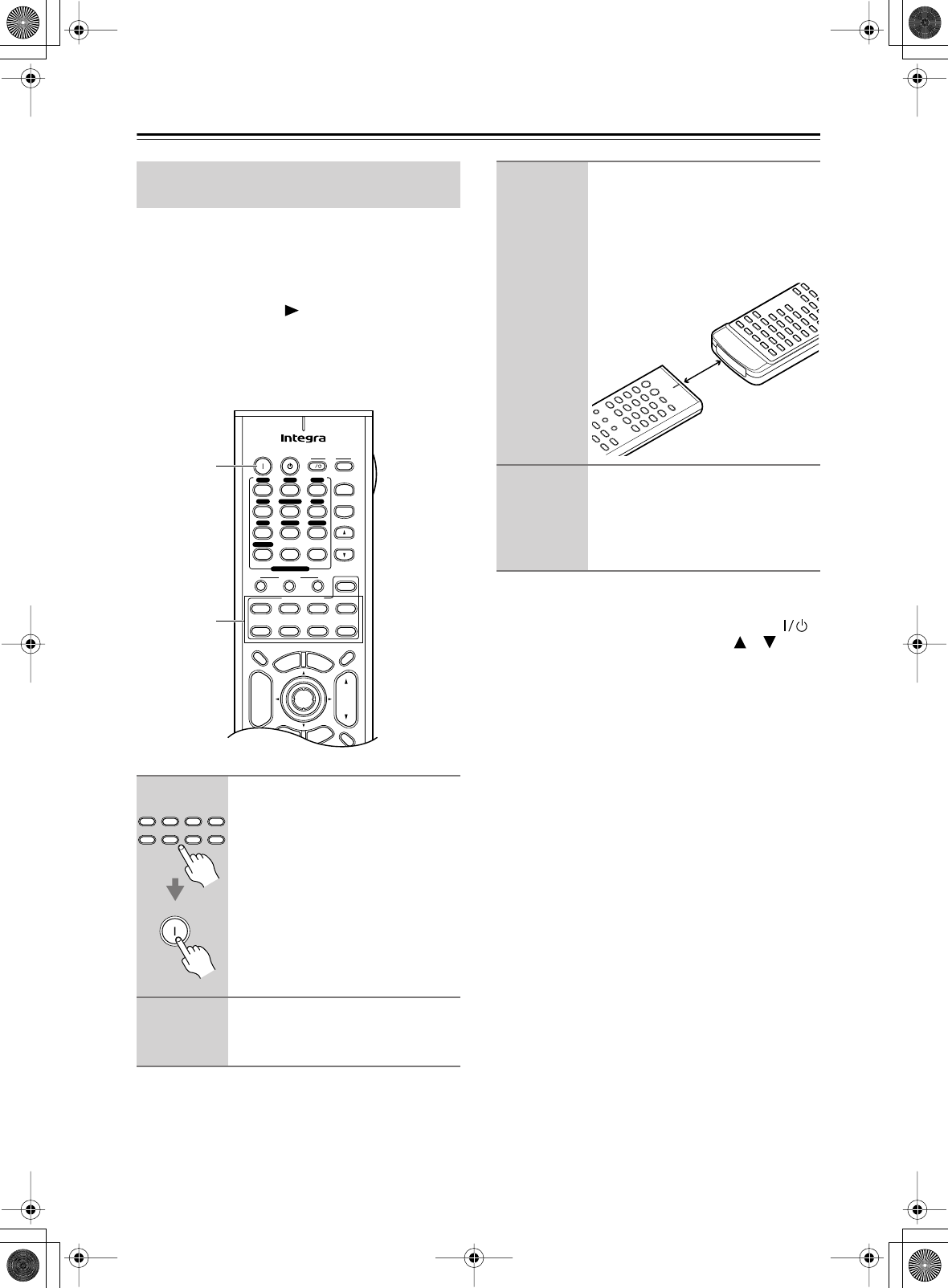
88
Controlling Other Components
—Continued
The AV receiver’s remote controller can learn the com-
mands of other remote controllers simply by pointing
them at each other. For example, by transmitting the Play
command from your CD player’s remote controller, the
remote controller can learn it and then transmit the same
command when its Play [ ] button is pressed in CD
mode.
This is convenient when you want to add commands to
buttons after entering a remote control code (page 80).
Notes:
• The following buttons cannot be taught new com-
mands: Remote Mode, Macro [1], [2], [3], TV [ ],
TV [Input], TV CH [+]/[–], TV VOL [ ]/[ ].
• The AV receiver’s remote controller can learn up to
approximately 150 commands. However, the com-
mands of some remote controllers may use a lot of
memory, in which case, this will be reduced.
•By default, the AV receiver’s remote controller knows
the commands for controlling an Integra CD player,
cassette deck, DVD player, and MD player (e.g., Play,
Stop, Pause, etc., buttons). These buttons can learn
new commands, although the defaults will be restored
if the remote controller is reset.
•To learn a new command for a button that has already
learned one, simply repeat this procedure.
• Like most remote controllers, the AV receiver’s
remote controller uses infrared. Commands from
remote controllers that don’t use infrared cannot be
learnt.
• When the remote controller’s batteries expire, all
learned commands will be lost and will have to be
learned all over again, so don’t discard your other
remote controllers.
Learning Commands from Another
Remote Controller
1
While holding down the Remote
Mode button that you want to
learn the command, press the
[On] button.
2
On the AV receiver’s remote con-
troller, press the button you want
to learn the new command.
On Standby TV
Display Muting
E
x
i
t
G
u
i
d
e
Prev
CH
TV CH
TV VOL
--
/
---
Dimmer
Tape
TV
Input
Sleep
Input
I
Enter
T
o
p
M
e
n
u
M
e
n
u
S
e
t
u
p
R
e
t
u
r
n
VOL
CH
Disc
SATTV VCR Cable
DVD
Receiver
CD
+10 0 Clear
123
456
789
+
-
Macro
123
MD/CDR
+
-
Input Selector
V1V2V3
CD
Phono
Tape
V4DVD
Multi CH
Tuner
Remote Mode
Zone 2
1
1, 4
Tape
SATTV VCR Cable
DVD
Receiver
CD
MD/CDR
Remote Mode
On
3
Point the remote controllers at
each other, about 2 to 6 inches
(5–15 cm) apart, and then, on the
other remote controller, press the
button whose command you
want to learn.
4
To teach the AV receiver’s remote
controller more new commands,
repeat steps 2 and 3.
Press the [On] button when you’ve fin-
ished.
About 2 to 6
inches (5–15 cm
RC-585M/586M
DTR-6.5,5.5_En.book Page 88 Wednesday, July 28, 2004 9:07 AM
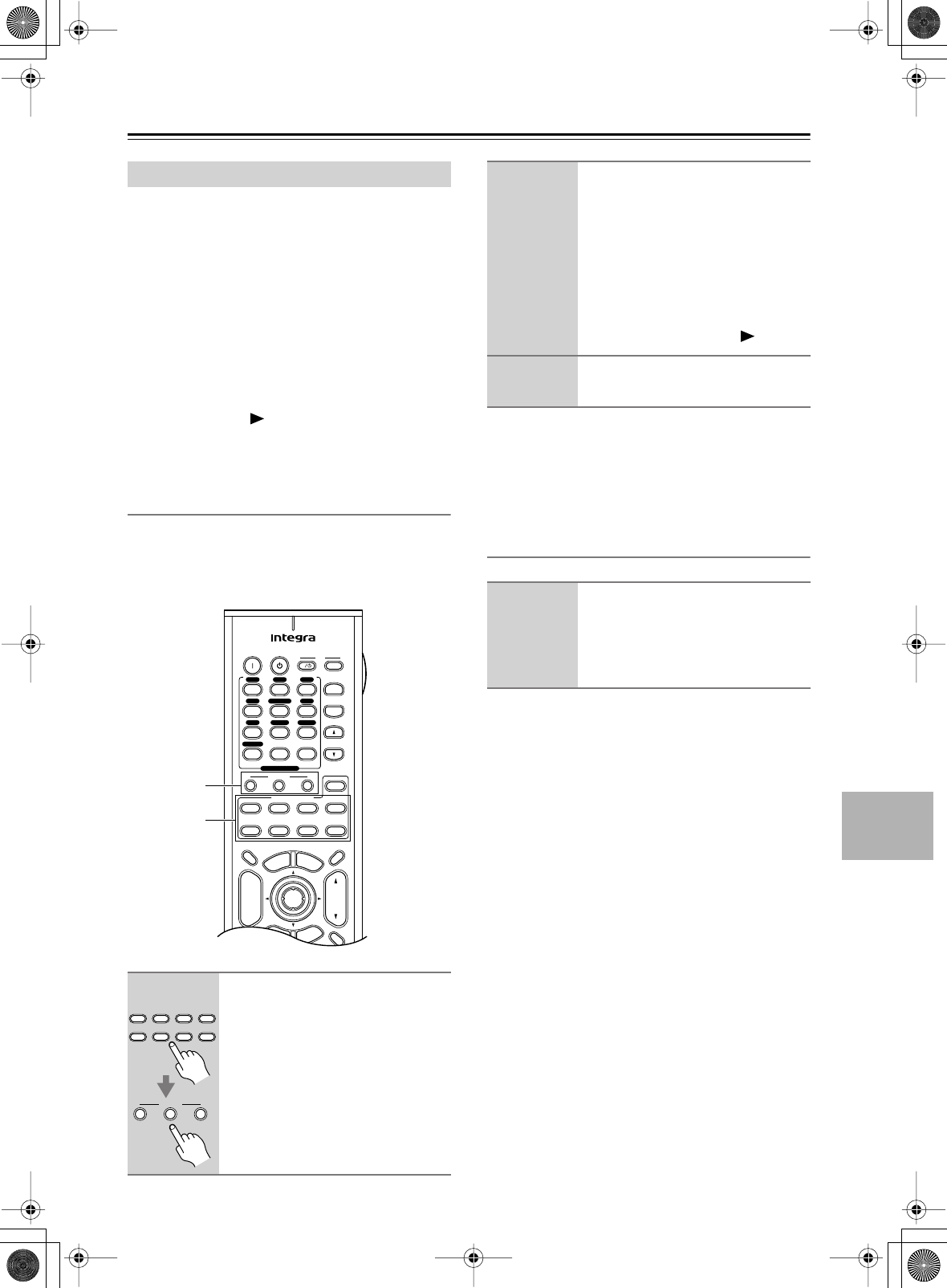
89
Controlling Other Components
—Continued
With the Macro function, you can program the remote
controller’s Macro buttons to perform a sequence of
actions with just one button press. For example, nor-
mally you need to perform the following actions to play
a CD:
1. Press the Remote Mode [[
[[RR
RRee
eecc
ccee
eeiiiivv
vvee
eerr
rr]]
]] bb
bbuu
uuttttttttoo
oonn
nn
to
select Receiver mode.
2. Press the [On] button to turn on the AV receiver.
3. Press the [CD] Input Selector button to select the
CD input source.
4. Press the Remote Mode [CD] button to select the
CD remote controller mode.
5. Press the Play [ ] button to start playback on the
CD player.
With the Macro function, you can program one of the
Macro buttons to perform all five actions in one go.
Making Macros
There are three Macro buttons, and each button can be
programmed with a different macro in each remote con-
troller mode. Each macro can perform up to eight
actions.
Notes:
• If after programming a macro you teach one of the
buttons in that macro a new command, then the macro
will no longer work properly. In this case, you must
program the macro again.
Running Macros
Programmed macros can be run as follows.
Using Macros
1
While holding down the Remote
Mode button for the mode that
you want to learn the macro,
press Macro button [1], [2], or [3].
The Remote indicator lights up.
On Standby TV
Display Muting
E
x
i
t
G
u
i
d
e
Prev
CH
TV CH
TV VOL
--
/
---
Dimmer
Tape
TV
Input
Sleep
Input
I
Enter
T
o
p
M
e
n
u
M
e
n
u
S
e
t
u
p
R
e
t
u
r
n
VOL
CH
Disc
SATTV VCR Cable
DVD
Receiver
CD
+10 0 Clear
123
456
789
+
-
Macro
123
MD/CDR
+
-
Input Selector
V1V2V3
CD
Phono
Tape
V4DVD
Multi CH
Tuner
Remote Mode
Zone 2
1
1
Tape
SATTV VCR Cable
DVD
Receiver
CD
MD/CDR
Remote Mode
Macro
123
2
On the remote controller, press
the buttons whose actions you
want to program into the macro
in the order you want them per-
formed.
For example, to program the previous
CD example into a macro, press the fol-
lowing buttons: Remote Mode
[Receiver], [On], Input Selector [CD],
Remote Mode [CD], Play [ ].
3
When you’ve finished, press the
Macro button again.
1
Press the Macro [1], [2], or [3]
button.
The actions in the macro are performed
in the order in which they were pro-
grammed.
DTR-6.5,5.5_En.book Page 89 Wednesday, July 28, 2004 9:07 AM

90
Troubleshooting
If you have any trouble using the AV receiver, look for a
solution in this section. If you can’t resolve the issue
yourself, contact the dealer from whom you purchased
this unit.
Can’t turn on the AV receiver?
•Make sure that the power cord is properly plugged into
the wall outlet.
•Unplug the power cord from the wall outlet, wait five
seconds or more, then plug it in again.
The AV receiver turns off as soon as it’s turned
on?
• The amp protection circuit has been activated.
Remove the power cord from the wall outlet immedi-
ately and contact the dealer from whom you purchased
this unit.
There’s no sound, or it’s very quiet?
•Make sure that all audio connecting plugs are pushed
in all the way (page 21).
• Make sure that the inputs and outputs of all compo-
nents are connected properly (page 21).
• Make sure that the polarity of the speaker cables is
correct, and that the bare wires are in contact with
metal part of each speaker terminal (page 23)
• Make sure that the input source is properly selected
(page 53).
• Make sure that the speaker cables are not shorting.
•Check the volume. It can be set to MIN, 1 through 99,
or MAX (page 53). The AV receiver is designed for
home theater enjoyment. It has a wide volume range,
allowing precise adjustment.
• If the MUTING indicator is shown on the display,
press the remote controller’s [Muting] button to
unmute the AV receiver (page 54).
•While a pair of headphones is connected to the Phones
jack, no sound is output by the speakers (page 54).
• Check the digital audio output setting on the con-
nected device. On some games consoles, such as those
that support DVD, the default setting is off.
•With some DVD-Video discs, you need to select an
audio output format from a menu.
•For the DTR-5.5, if your turntable doesn’t have a
built-in phono preamp, you must connect one between
it and the AV receiver. If your turntable uses an MC
cartridge, you must connect an MC head amp, or an
MC transformer and phono equalizer.
•For the DTR-6.5, if your turntable uses an MC car-
tridge, you must connect an MC head amp or an MC
transformer (see page 36).
•Make sure that none of the connecting cables are bent,
twisted, or damaged.
• Not all listening modes use all speakers (page 60).
•Specify the speaker distances (page 48) and adjust the
individual speaker levels (page 50).
• Make sure that the speaker setup microphone is not
still connected.
Only the front speakers produce sound?
• When the Stereo listening mode is selected, only the
front speakers and subwoofer produce sound.
• When the Direct or Pure Audio listening mode is
selected, only the front speakers produce sound.
• Make sure the speakers are configured correctly
(page 46).
Only the center speaker produces sound?
• If you use the Pro Logic IIx Movie or Pro Logic IIx
Music listening mode with a mono source, such as an
AM radio station or mono TV program, the sound is
concentrated in the center speaker.
• Make sure the speakers are configured correctly
(page 46).
The surround speakers produce no sound?
•When the Stereo, Direct, or Pure Audio listening mode
is selected, the surround speakers produce no sound
(page 60).
• Depending on the source and current listening mode,
not much sound may be produced by the surround
speakers. Try selecting another listening mode.
• Make sure the speakers are configured correctly
(page 46).
The center speaker produces no sound?
• When the Mono, Stereo, Direct, Pure Audio, or
Orchestra listening mode is selected, the center
speaker produces no sound (page 61).
• Make sure the speakers are configured correctly
(page 46).
The surround back speakers produce no
sound?
• The surround back speakers are not used with all lis-
tening modes. Select another listening mode
(page 60).
• Not much sound may be produced by the surround
back speakers with some sources.
• Make sure the speakers are configured correctly
(page 46).
Power
Audio
DTR-6.5,5.5_En.book Page 90 Wednesday, July 28, 2004 9:07 AM

91
Troubleshooting
—Continued
The subwoofer produces no sound?
•When you play source material that contains no infor-
mation in the LFE channel, the subwoofer produces
no sound.
• Make sure the speakers are configured correctly
(page 46).
There’s no sound with a certain signal format?
• Check the digital audio output setting on the con-
nected device. On some games consoles, such as those
that support DVD, the default setting is off.
•With some DVD-Video discs, you need to select an
audio output format from a menu.
•Depending on the input signal, some listening modes
cannot be selected (page 59).
Can’t select the DTS-ES Discrete/Matrix or THX
Surround EX (DTR-6.5 only) listening modes?
• These modes cannot be selected when no surround
back speakers are connected, or the Zone 2 speakers
are being used.
Can’t get 6.1 playback?
• If no surround back speakers are connected, or the
Zone 2 speakers are being used, 6.1 playback is not
possible.
The volume cannot be set to 99?
• When the levels of all speakers have been calibrated
(page 50), the maximum volume setting may change.
Noise can be heard?
• Using cable ties to bundle audio cables with power
cords, speaker cables, and so on may degrade the
audio performance, so don’t do it.
• An audio cable may be picking up interference. Try
repositioning your cables.
The Late Night function doesn’t work?
• Make sure the source material is Dolby Digital
(page 62).
The DVD analog multichannel input doesn’t
work?
• Check the DVD analog multichannel input connec-
tions (page 29).
•To select the DVD analog multichannel input, press
the [Multi CH] input selector button.
• Check the audio output settings on your DVD player.
About DTS signals
• When DTS program material ends and the DTS bit-
stream stops, the AV receiver remains in DTS listen-
ing mode and the DTS indicator remains on. This is to
prevent noise when you use the pause, fast forward, or
fast reverse function on your player. If you switch your
player from DTS to PCM, because the AV receiver
does not switch formats immediately, you may not
hear any sound, in which case you should stop your
player for about three seconds, and then resume play-
back.
•With some CD and LD players, you won’t be able to
playback DTS material properly even though your
player is connected to a digital input on the AV
receiver. This is usually because the DTS bitstream
has been processed (e.g., output level, sampling rate,
or frequency response changed) and the AV receiver
doesn’t recognize it as a genuine DTS signal. In such
cases, you may hear noise.
•When playing DTS program material, using the pause,
fast forward, or fast reverse function on your player
may produce a short audible noise. This is not a mal-
function.
There’s no picture?
•Make sure that all video connecting plugs are pushed
in all the way (page 21).
•Make sure that each video component is properly con-
nected.
•If your video component is connected to a component
video input, your TV must be connected to the compo-
nent video output (page 26).
• On your TV, make sure that the video input to which
the AV receiver is connected is selected.
• While the Pure Audio listening mode is selected, the
video circuits are turned off and the AV receiver out-
puts no video signals.
The onscreen menus don’t appear?
• Make sure that the video settings are correct
(page 43).
• On your TV, make sure that the video input to which
the AV receiver is connected is selected.
• Depending on the display device, when the “b. Scan
Mode” setting on the “6-3. OSD Setup” menu is set to
Non-Interlaced, the onscreen setup menus may not
appear. If this happens, use the AV receiver’s display
and change that setting to Interlaced.
Video
DTR-6.5,5.5_En.book Page 91 Wednesday, July 28, 2004 9:07 AM

92
Troubleshooting
—Continued
Reception is noisy, FM stereo reception is
noisy, or the FM STEREO indicator doesn’t
appear?
• Relocate your antenna.
•Move the AV receiver away from your TV or com-
puter.
• Listen to the station in mono (page 56).
•When listening to an AM station, operating the remote
controller may cause noise.
•Passing cars and airplanes can cause interference.
• Concrete walls weaken radio signals.
• If nothing improves the reception, install an outdoor
antenna.
The remote controller doesn’t work?
•Make sure that the batteries are installed with the cor-
rect polarity (page 13).
•Install new batteries. Don’t mix different types of bat-
teries, or old and new batteries (page 13).
• Make sure that the remote controller is not too far
away from the AV receiver, and that there’s no
obstruction between the remote controller and the AV
receiver’s remote control sensor (page 13).
• Make sure that the AV receiver is not subjected to
direct sunshine or inverter-type fluorescent lights.
Relocate if necessary.
•If the AV receiver is installed in a rack or cabinet with
colored-glass doors, the remote controller may not
work reliably when the doors are closed.
•Make sure you’ve selected the correct remote control-
ler mode (page 13).
• When using the remote controller to control other
manufacturers’ AV components, some buttons may
not work as expected.
• Make sure you’ve entered the correct remote control
code.
Can’t control other components?
• If it’s an Integra component, make sure that the
cable and analog audio cable are connected properly.
Connecting only an cable won’t work (page 37).
•Make sure you’ve selected the correct remote control-
ler mode (page 14).
•If you connect an MD recorder or CD recorder to the
TAPE jacks, be sure to set make the necessary setting
(pages 52 and 80).
• When learning commands, make sure that the trans-
mitting ends of both remote controllers are pointing at
each other.
• Are you trying to learn from a remote controller that
cannot be used for learning? Some commands cannot
be learnt, especially those that transmit several
instructions with a single button press.
• The wrong remote control code has been entered.
•The entered remote control code may not be correct. If
more than one code is listed, try each one.
•With some AV components, certain buttons may not
work as expected, and some may not work at all.
•To control Integra components, point the remote con-
troller at the AV receiver.
•To control another manufacturer’s component, point
the remote controller at that component.
Can’t record?
• On your recorder, make sure the correct input is
selected (e.g., digital or analog).
Zone 2 has turned off?
•Was the Sleep function set? The Sleep function turns
off Zone 2 as well as the AV receiver. To set the Sleep
function for Zone 2 only, see page 77.
There’s no sound?
• Since the Zone 2 function and the REC OUT outputs
use the same circuitry, you cannot use Zone 2 and
record at the same time. When the [Rec Out] button is
pressed, Zone 2 is turned off.
• Only components connected to analog inputs can be
played in Zone 2.
Tuner
Remote Controller
Recording
Zone 2
DTR-6.5,5.5_En.book Page 92 Wednesday, July 28, 2004 9:07 AM
93
Troubleshooting
—Continued
The sound changes when I connect my head-
phones?
•When a pair of headphones is connected, the listening
mode is set to Stereo, unless it’s already set to Stereo,
Direct, or Pure Audio. When you disconnect the head-
phones, the previous listening mode will be resumed.
The speaker volume cannot be set as required?
• When the Automatic Speaker Setup function is used,
or the volume is adjusted on the onscreen setup
menus, the maximum possible volume setting may
change.
The speaker distance cannot be set as
required?
•In some cases, corrected values suitable for home the-
ater use may be set automatically.
The display doesn’t work?
• The display is turned off when the Pure Audio listen-
ing mode is selected.
•Actions are not displayed on the TV or projector that’s
connected to the COMPONENT VIDEO OUT.
How do I change the language of a multiplex
source?
•Use the “a. Input Channel” setting on the “3-5. Multi-
plex” menu to select Main or Sub (page 67).
Others
The AV receiver contains a microcomputer for signal pro-
cessing and control functions. In very rare situations,
severe interference, noise from an external source, or
static electricity may cause it to lockup. In the unlikely
event that this happens, unplug the power cord from the
wall outlet, wait at least five seconds, and then plug it
back in again.
Onkyo is not responsible for damages (such as CD
rental fees) due to unsuccessful recordings caused by
the unit’s malfunction. Before you record important
data, make sure that the material will be recorded cor-
rectly.
Resetting the AV receiver to its factory defaults
To reset the AV receiver to its factory defaults, turn it on
and, while holding down the [VIDEO 1] button, press
the [Standby/On] button. “CLEAR” will appear on the
display and the AV receiver will enter Standby mode.
The AV receiver uses a battery-less memory backup
system in order to retain radio presets and other set-
tings when it’s unplugged or in the case of a power fail-
ure. Although no batteries are required, the AV receiver
must be plugged into an AC outlet in order to charge the
backup system.
DTR-6.5,5.5_En.book Page 93 Wednesday, July 28, 2004 9:07 AM

94
Specifications (DTR-6.5)
Amplifier Section
Video Section
Tuner Section
■FM
■AM
General
■Video Inputs
■Video Outputs
■Audio Inputs
■Audio Outputs
■Other Jacks
Specifications and features are subject to change without
notice.
Power Output
(2 channels driven): 100 W + 100 W (8Ω,20Hz–20kHz,FTC)
130 W + 130 W (6Ω,1kHz,DIN)
160 W + 160 W (6Ω,1kHz,JEITA)
Dynamic Power 230 W + 230 W (3Ω,Front)
170 W + 170 W (4Ω,Front)
115 W + 115 W (8Ω,Front)
THD (Total Harmonic
Distortion) 0.08 % (Power Rated)
Damping Factor 60 (Front,1kHz,8Ω)
Input Sensitivity and
Impedance 200 mV/ 47 kΩ (LINE)
2.5 mV/ 4.7 kΩ (PHONO MM)
Output Level and
Impeadance 200 mV/ 470 Ω (REC OUT)
Phono Overload 70 mV (MM 1kHz 0.5 %)
Frequency Response 10 Hz–100 kHz/ +1 dB-3 dB (Direct
mode)
Tone Control ±10 dB, 50 Hz (BASS)
±10 dB, 10 kHz (TREBLE)
SN Ratio 106 dB (LINEIHF-A)
80 dB (PHONO,IHF-A)
Speaker Impedance American : 6Ω~
other :4 Ω~
Input Sensitivity/Output
Level and Impedance 1 Vp-p /75Ω (Component and S-Video Y)
0.7 Vp-p /75Ω (Component Pb/Cb,Pr/Cr)
0.28 Vp-p /75Ω(S-Video C)
1 Vp-p /75Ω(Composite)
Component Video
Frequency Response 5 Hz – 50 MHz
Tuning Frequency RangeAmerican: 87.5 MHz– 107.9 MHz
Other : 87.5 MHz– 108.0 MHz
Usable Sensitivity Stereo; 17.2 dBf 2 µV(75Ω IHF)
Mono; 11.2 dBf 1 µV(75Ω IHF)
S/N Ratio Stereo; 70 dB (IHF-A)
Mono; 76 dB (IHF-A)
THD Stereo; 0.3 % (1kHz)
Mono 0.2 % (1kHz)
Frequency Response 30 Hz–15 kHz / ±1 dB
Stereo Separation 45 dB ( 1kHz )
Tuning Frequency RangeAmerican: 530 kHz–1700 kHz
Others: 522 kHz–1611 kHz
Usable Sensitivity 30 µV
S/N Ratio 40 dB
THD 0.70%
Power Supply American: AC 120 V, 60 Hz
Australian: AC 230-240 V, 50 Hz
Power Comsumption American : 8.1A
Others : 700 W
Stand-by Power
Comsumption 1.0 W
Dimensions(W x H x D) 435 W x 175 H x 428 D mm
17-1/8" W x 6-7/8" H x 16-7/8" D inches
Weight 15.2 kg
33.5 lbs
Component Video Input 1,2,3
S-Video Compatible Jack
Input DVD,VIDEO1,VIDEO2,VIDEO3,
VIDEO4
A/V Input DVD,VIDEO1,VIDEO2,VIDEO3,
VIDEO4
Component Video
Output OUT
S-Video Compatible Jack
Output MONITOR OUT,VIDEO1,VIDEO2
A/V Output MONITOR OUT,VIDEO1,VIDEO2
Digital Inputs Optical : 5 , 1 (Front Panel )
Coaxial : 2
Analog Inputs DVD(MULTICHANNEL),VIDEO1,VID
EO2,VIDEO3,VIDEO4,TAPE,CD,PHO
NO
Multichannel Inputs 6
Digital Outputs Optical : 1
Coaxial : 1
Analog Outputs TAPE,VIDEO1,VIDEO2
Multichannel Pre
Outputs 7
Subwoofer Pre Outputs 1
Speaker Outputs 9
Phones 1
RS-232 Control 1
IR Input/Output 1
12V Trigger Out 3
7_Appendix_En Page 94 Wednesday, July 28, 2004 11:40 AM

95
Specifications (DTR-5.5)
Amplifier Section
Video Section
Tuner Section
■
FM
■
AM
General
■
Video Inputs
■
Video Outputs
■
Audio Inputs
■
Audio Outputs
■
Other Jacks
Specifications and features are subject to change without
notice.
Power Output
(2 channels driven):
85 W + 85 W (8
Ω
,20Hz–20kHz, FTC)
120 W +120 W (6
Ω
,1kHz,DIN)
150 W + 150 W (6
Ω
,1kHz,JEITA)
Dynamic Power 220 W + 220 W (3
Ω
,Front)
165 W + 165 W (4
Ω
,Front)
100 W + 100 W (8
Ω
,Front)
THD (Total Harmonic
Distortion) 0.08 % (Power Rated)
Damping Factor 60 (Front,1kHz,8
Ω
)
Input Sensitivity and
Impedance 200 mV/ 47 k
Ω
(LINE)
Output Level and
Impeadance 200 mV/ 470
Ω
(REC OUT)
Frequency Response 10 Hz–100 kHz/ +1 dB-3 dB (Direct
mode)
Tone Control ±10 dB, 50 Hz (BASS)
±10 dB, 10 kHz (TREBLE)
SN Ratio 106 dB (LINEIHF-A)
Speaker Impedance American : 6
Ω
–
Others :4
Ω
–
Input Sensitivity/Output
Level and Impedance 1 Vp-p /75
Ω
(Component and S-Video Y)
0.7 Vp-p /75
Ω
(Component Pb/Cb,Pr/Cr)
0.28 Vp-p /75
Ω
(S-Video C)
1 Vp-p /75
Ω
(Composite)
Component Video
Frequency Response 5 Hz – 50 MHz
Tuning Frequency RangeAmierican; 87.5 MHz– 107.9 MHz
Others; 87.5 MHz– 108.0 MHz
Usable Sensitivity Stereo:17.2 dBf 2 µV(75
Ω
IHF)
Mono: 11.2 dBf 1 µV(75
Ω
IHF)
S/N Ratio Stereo: 70 dB (IHF-A)
Mono:76 dB (IHF-A)
THD Stereo: 0.3 % (1kHz)
Mono:0.2 % (1kHz)
Frequency Response 30 Hz–15 kHz / ±1 dB
Stereo Separation 45 dB ( 1kHz )
Tuning Frequency RangeAmerican; 530 kHz–1700 kHz
Others; 522 kHz–1611 kHz
Usable Sensitivity 30 µV
S/N Ratio 40 dB
THD 0.70%
Power Supply American: AC 120 V, 60 Hz
Australian: AC 230-240 V, 50 Hz
Power Comsumption American : 6.7A
Others: 650 W
Stand-by Power
Comsumption 1.0 W
Dimensions(W x H x D) 435 W x 175 H x 428 D mm
17-1/8" W x 6-7/8" H x 16-7/8" D inches
Weight 13.4 kg
29.5 lbs
Component Video Input 1,2,3
S-Video Compatible Jack
Input DVD,VIDEO1,VIDEO2,VIDEO3,
VIDEO4
A/V Input DVD,VIDEO1,VIDEO2,VIDEO3,
VIDEO4
Component Video
Output OUT
S-Video Compatible Jack
Output MONITOR OUT,VIDEO1,VIDEO2
A/V Output MONITOR OUT,VIDEO1,VIDEO2
Digital Inputs Optical :4(American)/ 3(other) 1 (Front
Panel )
Coaxial : 2
Analog Inputs DVD(MULTICHANNEL),VIDEO1,
VIDEO2,VIDEO3,VIDEO4,TAPE,CD
Multichannel Inputs 6
Digital Outputs 1 (Optical ) 0 (Coaxial )
Analog Outputs TAPE,VIDEO1,VIDEO2
Subwoofer Pre Outputs 1
Speaker Outputs 9
Phones 1
RS-232 Control 1
IR Input/Output 1
12V Trigger Out 3
7_Appendix_En Page 95 Wednesday, July 28, 2004 11:40 AM

96
SN 29343827
(C) Copyright 2004 ONKYO CORPORATION Japan. All rights reserved.
I0407-1
Integra Division of
ONKYO U.S.A. CORPORATION
18 park Way, Upper Saddle River, N.J. 07458, U.S.A.
Tel: 201-785-2600 Fax: 201-785-2650 http://www.integrahometheater.com
Integra Division of
ONKYO CORPORATION
Sales & Product Planning Div.: 2-1, Nisshin-cho, Neyagawa-shi, OSAKA 572-8540, JAPAN
Tel: 072-831-8023 Fax: 072-831-8124
En
* 2 9 3 4 3 8 2 7 *
DTR-6.5,5.5_En.book Page 96 Wednesday, July 28, 2004 9:07 AM
