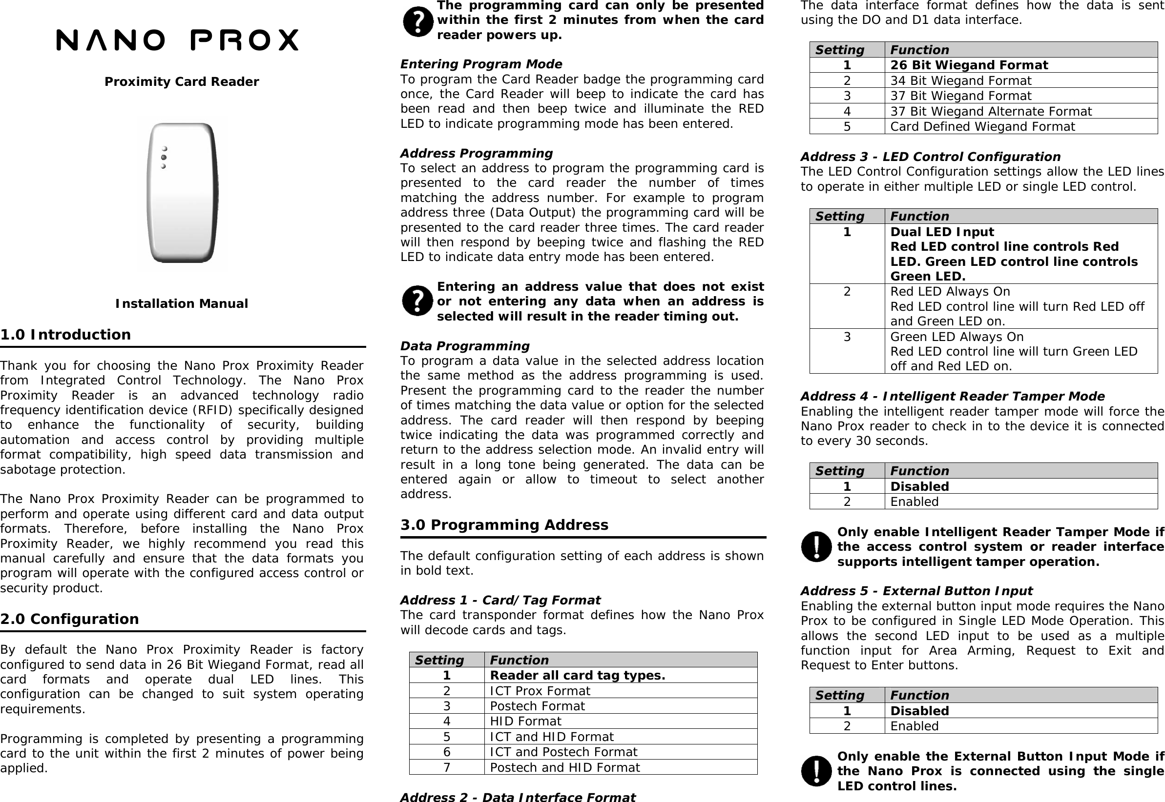
Integrated Control Technology 4060 Proximity Card Reader User Manual 4060 PRX NPROX

Integrated Control Technology Proximity Card Reader 4060 PRX NPROX

4060 PRX NPROX User Manual

  Nano PROX  Proximity Card Reader               Installation Manual  1.0 Introduction  Thank you for choosing the Nano Prox Proximity Reader from Integrated Control Technology. The Nano Prox Proximity Reader is an advanced technology radio frequency identification device (RFID) specifically designed to enhance the functionality of security, building automation and access control by providing multiple format compatibility, high speed data transmission and sabotage protection.  The Nano Prox Proximity Reader can be programmed to perform and operate using different card and data output formats. Therefore, before installing the Nano Prox Proximity Reader, we highly recommend you read this manual carefully and ensure that the data formats you program will operate with the configured access control or security product.   2.0 Configuration  By default the Nano Prox Proximity Reader is factory configured to send data in 26 Bit Wiegand Format, read all card formats and operate dual LED lines. This configuration can be changed to suit system operating requirements.  Programming is completed by presenting a programming card to the unit within the first 2 minutes of power being applied.   The programming card can only be presented within the first 2 minutes from when the card reader powers up.  Entering Program Mode To program the Card Reader badge the programming card once, the Card Reader will beep to indicate the card has been read and then beep twice and illuminate the RED LED to indicate programming mode has been entered.  Address Programming To select an address to program the programming card is presented to the card reader the number of times matching the address number. For example to program address three (Data Output) the programming card will be presented to the card reader three times. The card reader will then respond by beeping twice and flashing the RED LED to indicate data entry mode has been entered.  Entering an address value that does not exist or not entering any data when an address is selected will result in the reader timing out.  Data Programming To program a data value in the selected address location the same method as the address programming is used. Present the programming card to the reader the number of times matching the data value or option for the selected address. The card reader will then respond by beeping twice indicating the data was programmed correctly and return to the address selection mode. An invalid entry will result in a long tone being generated. The data can be entered again or allow to timeout to select another address.  3.0 Programming Address  The default configuration setting of each address is shown in bold text.  Address 1 - Card/Tag Format The card transponder format defines how the Nano Prox will decode cards and tags.  Setting  Function 1  Reader all card tag types. 2  ICT Prox Format  3 Postech Format 4 HID Format 5  ICT and HID Format 6  ICT and Postech Format 7  Postech and HID Format  Address 2 - Data Interface Format The data interface format defines how the data is sent using the DO and D1 data interface.  Setting  Function 1  26 Bit Wiegand Format 2  34 Bit Wiegand Format 3  37 Bit Wiegand Format 4  37 Bit Wiegand Alternate Format 5  Card Defined Wiegand Format  Address 3 - LED Control Configuration The LED Control Configuration settings allow the LED lines to operate in either multiple LED or single LED control.  Setting  Function 1  Dual LED Input Red LED control line controls Red LED. Green LED control line controls Green LED. 2  Red LED Always On Red LED control line will turn Red LED off and Green LED on. 3  Green LED Always On Red LED control line will turn Green LED off and Red LED on.  Address 4 - Intelligent Reader Tamper Mode Enabling the intelligent reader tamper mode will force the Nano Prox reader to check in to the device it is connected to every 30 seconds.  Setting  Function 1 Disabled 2 Enabled  Only enable Intelligent Reader Tamper Mode if the access control system or reader interface supports intelligent tamper operation.  Address 5 - External Button Input  Enabling the external button input mode requires the Nano Prox to be configured in Single LED Mode Operation. This allows the second LED input to be used as a multiple function input for Area Arming, Request to Exit and Request to Enter buttons.  Setting  Function 1 Disabled 2 Enabled  Only enable the External Button Input Mode if the Nano Prox is connected using the single LED control lines.
 4.0 Mounting  When mounting the Nano Prox Proximity Reader please respect the following guidelines.  • Avoid wiring the Nano Prox cables in the same conduit with AC power cables, lock power, or signal wiring. • Maintain all reader wiring a minimum of 12" (30cm) away from other wiring such as AC power, computer data wiring, telephone wiring and wiring to electric lock devices. • Avoid installing within 3.5 feet (1.1m) of computer monitors or CRTs. The minimum distance will vary depending on the type of monitor or CRT. • Avoid installing in proximity to sources of broad spectrum EMI noise such as motors, pumps, generators, DC to AC converters, uninterruptible power supplies, AC switching relays, light dimmers, computer monitors and CRTs. • Avoid installing in proximity to potential sources of high power RF signal transmitters such as cellular telephones and two way radios.   5.0 Wiring Connection  Two wiring methods can be used. Dual LED operation allows the signalling of both LED's independently using the LED control lines. Single LED allows a single LED line to control both LED colours.    Figure 1 - Dual LED Connection    Figure 2 - Single LED Connection  Using the recommended cables listed in the technical specifications in section 7, splice these cables together with the pigtail of the reader and seal the splice. Route the cable from the reader to the host controller. Connect the cables as shown in Figure 1 for Dual LED Operation or Figure 2 for Single LED Operation.  Do not connect the shield wires together at the reader cable splice. With the shield wire already terminated at the reader terminate the shield at the controller. For more information refer to Figure 1 and Figure 2.  6.0 Button Input Wiring Connection  Button input wiring configuration is shown in Figure 2. For programming options refer to the Protégé System Manual.    Figure 3 - Button Input Wiring  Connect a normally open button or switch as shown in figure 2 and complete the programming within the Protégé Integrated System for the functionality required.   External Button Input Mode and single LED operation must be enabled when using this wiring configuration.  7.0 Specifications  Power Supply   Voltage    12VDC (9.5 - 14.0VDC) Current    120mA (Peak, Reading)  Read Range      Card   Up to 10cm (4")  Tag   Up to 6cm (2.5")  Interface   Wiegand    Multiple Format 26, 34, 37 Bit     Data 0 and Data 1 Distance    150 Meters (500 feet)   Frequency  Field   125KHz Pulse Width Modulated  Cable Type      Multi Conductor  22Awg Alpha 5196, 5198     18Awg Alpha 5386, 5388     18Awg Beldon 9553  Temperature  Operating  -35˚- +65˚ Celsius    -31˚ - 149˚ Fahrenheit  *Specifications are subject to change without notice, please visit www.integratedcontroltechnology.com for the updated information. Read range is specified using an ICT card format and the card is presented parallel to the reader using installation procedures detailed in this manual without any electrical interference present.

Navigation menu