Integrated Control Technology 4115 Proximity Card and Pin Reader User Manual Multi PROX
Integrated Control Technology Proximity Card and Pin Reader Multi PROX
UserManual.wiki
>
Integrated Control Technology
>
4115 User Manual
UAU4115 User Manual
Navigation menu
Upload a User Manual
Namespaces
Wiki Guide
HTML
PDF
Info
Views
User Manual
Discussion / Help
Navigation
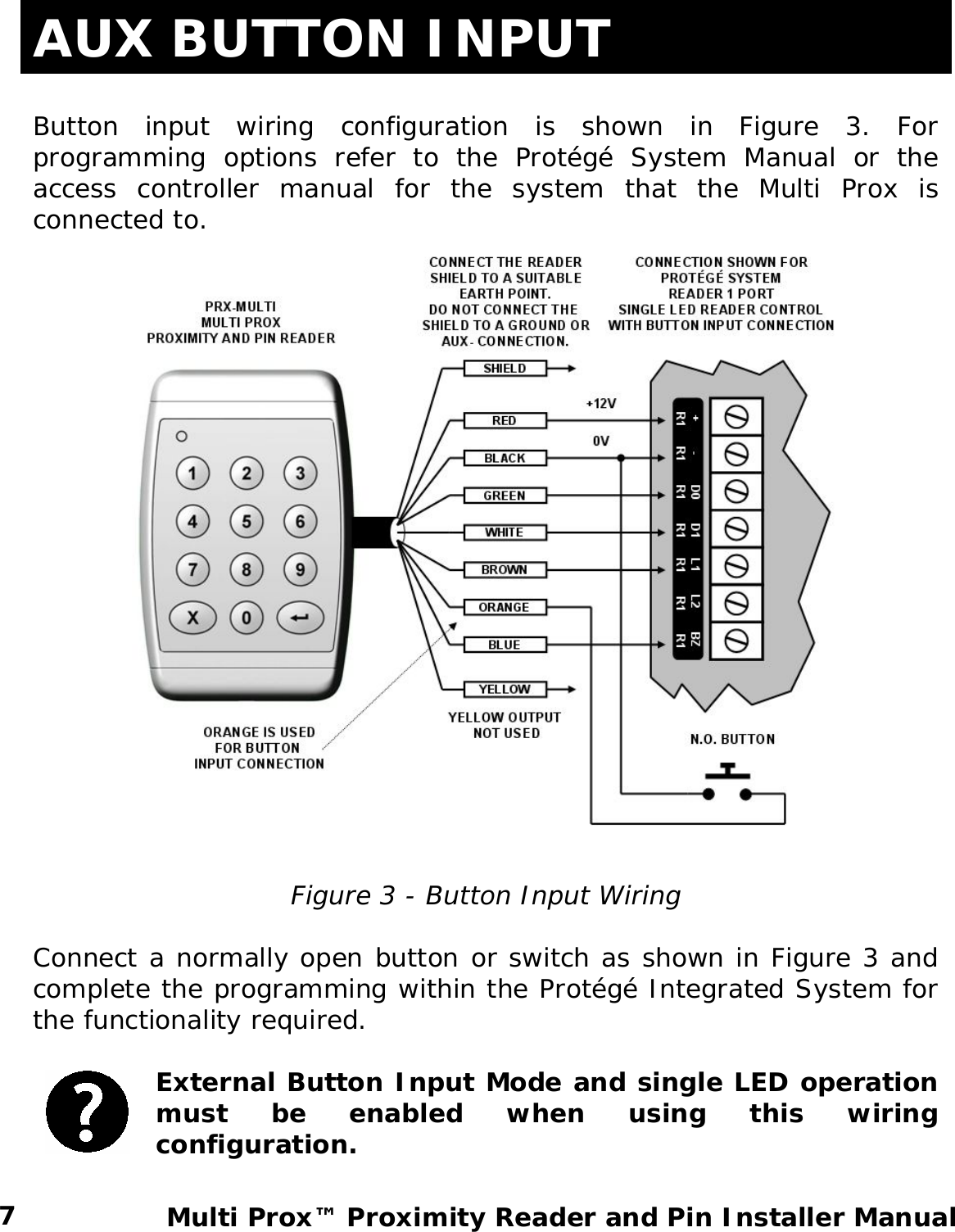
![LEGEND Indicates a warning or advisory message relating to the section or location. Indicates a hint or suggestion that relates to the section or location. [TEXT] Bold text enclosed in brackets is used to show a section number or address of a programmable option or information on programming shortcut sequences. Italics Italic text shows a reference to a section or page. TERMINOLOGY To ensure that you program the Multi Prox effectively please familiarize yourself with the following terms used throughout this manual. Wiegand The data transmission method used to communicate data to a controller or reader expansion device. Data is sent on a D0 (Data 0) and D1 (Data 1) interface in an open collector connection. Programming Card The Nano Prox Series of readers utilize built in programming functions that allow many options to be configured. To program these options you must have a Programming Card. These are typically marked with the text “ICT Programming Card” in place of the normal facility code and card number. Facility Code The facility code is the code that is common to a group of cards or facility; this is also referred to as the site code or family number. Facility codes are not normally printed on a card. 2 Multi Prox™ Proximity Reader and Pin Installer Manual](https://usermanual.wiki/Integrated-Control-Technology/4115/User-Guide-776438-Page-5.png)