Integrated Control Technology PRX-TSEC 13.56 MHz AND 125 KHz PROXIMITY CARD READER User Manual
Integrated Control Technology 13.56 MHz AND 125 KHz PROXIMITY CARD READER
User Manual

PRX-TSEC
TSEC Multi-Technology Card Reader
Installation Manual

2 PRX-TSEC TSEC Multi-Technology Card Reader Installation Manual | May 2014
The specifications and descriptions of products and services contained in this document were correct at the
time of printing. Integrated Control Technology Limited reserves the right to change specifications or withdraw
products without notice. No part of this document may be reproduced, photocopied, or transmitted in any form
or by any means (electronic or mechanical), for any purpose, without the express written permission of
Integrated Control Technology Limited. Designed and manufactured by Integrated Control Technology Limited.
Protege® and the Protege® Logo are registered trademarks of Integrated Control Technology Limited. All other
brand or product names are trademarks or registered trademarks of their respective holders.
Copyright © Integrated Control Technology Limited 2003-2014. All rights reserved.
Publication Date: May 2014

PRX-TSEC TSEC Multi-Technology Card Reader Installation Manual | May 2014 3
Contents
1Welcome _________________________________________________________________ 5
1.1Document Conventions ................................................................................................. 5
2TSEC Editions ____________________________________________________________ 6
3Mifare Technology _________________________________________________________ 7
3.1About Mifare .................................................................................................................. 7
3.2Mifare Modules .............................................................................................................. 7
Readers ......................................................................................................................... 7
Cards ............................................................................................................................. 7
3.3About ICT Secured Mifare Card Format ........................................................................ 8
Readers ......................................................................................................................... 8
3.4About Mifare DESFire EV1 ............................................................................................ 8
Readers ......................................................................................................................... 8
Cards ............................................................................................................................. 8
4Mounting _________________________________________________________________ 9
4.1Mounting Instructions .................................................................................................... 9
5Wiegand Connection ______________________________________________________ 10
6RS-485 Connection _______________________________________________________ 11
7Programming Interface ____________________________________________________ 12
7.1Installer Programming ................................................................................................. 12
7.2Entering Programming Mode ...................................................................................... 12
8Configuration ____________________________________________________________ 13
8.1125KHz Reading Mode ............................................................................................... 13
8.2DESFire Reading Mode ............................................................................................... 13
8.3Mifare Reading Mode .................................................................................................. 14
8.4Interface ....................................................................................................................... 15
8.5LED Function ............................................................................................................... 15
8.6Backlight ...................................................................................................................... 15
8.7Default Sector .............................................................................................................. 15
8.8Encryption Keys .......................................................................................................... 16
8.9Save and Restart ......................................................................................................... 17
9Technical Diagram ________________________________________________________ 18
10Technical Specifications ___________________________________________________ 19

4 PRX-TSEC TSEC Multi-Technology Card Reader Installation Manual | May 2014
11UL and ULC Installation Requirements ______________________________________ 20
11.1CAN/ULC-S319-05 ...................................................................................................... 20
11.2UL294 .......................................................................................................................... 20
12FCC Compliance Statements ______________________________________________ 21
13Industry Canada Statement ________________________________________________ 22
14Ordering Information ______________________________________________________ 23
15Warranty ________________________________________________________________ 24
16Contact _________________________________________________________________ 25
PRX-TSEC TSEC Multi-Technology Card Reader Installation Manual | May 2014 5
1 Welcome
Thank you for choosing the TSEC Card Reader from Integrated Control Technology. The TSEC Reader is an
advanced technology high frequency smart card radio frequency identification device (RFID) specifically
designed to enhance the functionality of security, building automation and access control by providing multiple
format compatibility, high speed data transmission and sabotage protection.
The TSEC Reader is designed to operate as a Wiegand Proximity Reader or using Intelligent RS-485
Communications, and can be programmed to read and output different card formats.
Before installing this product, we highly recommend you read this manual carefully and ensure that the data
formats you program will operate with the configured access control or security product.
Current features include:
Multi card technology provides support for DESFire, Mifare, and 125KHz cards
Encrypted RS-485 or standard Wiegand connection
Fully encapsulated design with environment IP Rating of IP65 for outdoor and indoor operation
Bi color LED (blue and green) with independent or single LED control
Programmable Wiegand data formats from 26 or 34 Bit with card configured output
Keypad output on Wiegand data using 4 Bit buffered, 26 Bit, 34 Bit and ARK formats (keypad versions only)
Read range up to 60mm (2.36") with proximity ISO cards
When receiving this product you should find the kit contains the items listed below. If you do not have the
correct contents, please contact your distributor immediately.
TSEC Multi-Technology Card Reader Installation Guide
TSEC Card Reader
M3 x 8mm Plastite screw
Mounting template sticker
For more information on the TSEC Card Reader range and other Integrated Control Technology products please
visit the ICT website (http://www.ict.co).
1.1 Document Conventions
This document uses the following conventions:
Important warnings or cautionary messages to prevent equipment damage, data loss, or other
similar conditions
i
Notes with additional information such as an explanation, a comment, or a clarification about the
subject
Tips containing practical information that may help you solve a problem or describing actions that
may save you time
UL
ULC
Information relating to UL and ULC compliance
[TEXT] Bold text enclosed in brackets is used to show a section number or address of a programmable
option or information on programming shortcut sequences

6 PRX-TSEC TSEC Multi-Technology Card Reader Installation Manual | May 2014
2 TSEC Editions
The TSEC Reader comes in three main editions (Standard, Extra, and Mini) and with a range of optional
features. Each edition is available with support for either 125KHz or Mifare/DESFire cards. The Standard and
Extra are also available in a combo model combining support for Mifare, DESFire, and 125 KHz cards from a
single reader, and with an optional keypad. All models are available in either black or white.
Keypad 125KHz Mifare/DESFire
Standard
PRX-TSEC-STD
TSEC Standard Card Reader
PRX-TSEC-STD-KP
TSEC Standard Card Reader with Keypad
PRX-TSEC-STD-125
TSEC Standard 125KHz Card Reader
PRX-TSEC-STD-125-KP
TSEC Standard 125KHz Card Reader with Keypad
PRX-TSEC-STD-DF
TSEC Standard DESFire Card Reader
PRX-TSEC-STD-DF-KP
TSEC Standard DESFire Card Reader with Keypad
Extra
PRX-TSEC-EXTRA
TSEC Extra Card Reader
PRX-TSEC-EXTRA-KP
TSEC Extra Card Reader with Keypad
PRX-TSEC-EXTRA-125
TSEC Extra 125KHz Card Reader
PRX-TSEC-EXTRA-125-KP
TSEC Extra 125KHz Card Reader with Keypad
PRX-TSEC-EXTRA-DF
TSEC Extra DESFire Card Reader
PRX-TSEC-EXTRA-DF-KP
TSEC Extra DESFire Card Reader with Keypad
Mini
PRX-TSEC-MINI
TSEC Mini Card Reader
PRX-TSEC-MINI-125
TSEC Mini 125KHz Card Reader
PRX-TSEC-MINI-DF
TSEC Mini DESFire Card Reader

PRX-TSEC TSEC Multi-Technology Card Reader Installation Manual | May 2014 7
3 Mifare Technology
3.1 About Mifare
Based on the international standard ISO/IEC 14443 Type A, Mifare is a technology used for contactless RFID
smart card systems consisting of card and reader components.
The most widely deployed RFID technology in the world and used in thousands of diverse applications, Mifare
has established an excellent reputation as a technology that delivers convenience and flexibility for contactless
RFID.
Fully compliant with the international standard ISO/IEC 14443 Type A
Proven and reliable, with more than 1 billion smart card ICs and 7 million reader components sold Mifare
has a market share of 80% in the automatic fare collection industry (Source: Frost & Sullivan 2001)
Future-proof product portfolio covering reader components as well as contactless and dual interface smart
card ICs
Multi-application memory to store several services on the same card allowing many integration possibilities
Fast transaction speed
High security and fraud protection
3.2 Mifare Modules
The Mifare products can be expanded to accommodate large numbers of modules using the encrypted RS-485
Network. Modules that are currently available are listed below. Integrated Control Technology provides a
number of reader and tag/card options in the Mifare range. You can take advantage of the ICT Mifare product
range while transitioning from legacy equipment using our dual technology cards which feature both low security
formats and Mifare. For more information, please contact our support team (see page 25).
Readers
Mifare Desfire Nano Proximity Card Reader (PRX-NPROX-DF)
TSEC Multi-Technology Standard Card Reader (PRX-TSEC-STD)
TSEC Multi-Technology Standard Card and PIN Reader (PRX-TSEC-STD-KP)
TSEC Multi-Technology Extra Card Reader (PRX-TSEC-EXTRA)
TSEC Multi-Technology Extra Card and PIN Reader (PRX-TSEC-EXTRA-KP)
TSEC Multi-Technology Mini Card Reader (PRX-TSEC-MINI)
Cards
Mifare 1K (S50) Proximity Clamshell Card (PRX-CLAM-MF)
Mifare 1K (S50) Proximity Card ISO (PRX-ISO-MF)
Mifare 1K (S50) Proximity Card ISO Mag (PRX-ISO-MAG-MF)
Mifare 1K (S50) Proximity Standard Key Tag (PRX-TAG-MF)
Mifare 1K (S50) Proximity Blue Key Tag (PRX-TAG-MF-BLU)
Mifare Desfire EV1 Proximity Card ISO 2K (PRX-ISO-DF)
Mifare Desfire EV1 Proximity Blue Key Tag 2K (PRX-TAG-DF-BLU)

8 PRX-TSEC TSEC Multi-Technology Card Reader Installation Manual | May 2014
3.3 About ICT Secured Mifare Card Format
ICT Secured Mifare is the compromise between secured card and cost. Card data is protected with a diversified
authentication key and encrypted with an AES256 algorithm. These cards are not as secure as DESFire EV1 but
still provide high security against cloning. This card mode can be used on all Mifare 1K (S50) cards and tags.
Readers
Mifare Desfire Nano Proximity Card Reader (PRX-NPROX-DF)
TSEC Multi-Technology Standard Card Reader (PRX-TSEC-STD)
TSEC Multi-Technology Standard Card and PIN Reader (PRX-TSEC-STD-KP)
TSEC Multi-Technology Extra Card Reader (PRX-TSEC-EXTRA)
TSEC Multi-Technology Extra Card and PIN Reader (PRX-TSEC-EXTRA-KP)
TSEC Multi-Technology Mini Card Reader (PRX-TSEC-MINI)
3.4 About Mifare DESFire EV1
Mifare DESFire EV1 is an ideal solution for service providers wanting to use multi-application smart cards in
transport schemes, e-government or identity applications. It complies fully with the requirements for fast and
highly secure data transmission, flexible memory organization, and interoperability with existing infrastructure.
Fully compliant with the international standard ISO/IEC 14443 Type A 1-4
Available in 2, 4 and 8 Kbytes EEPROM version with fast programming
Secure, high speed command set
Unique 7-byte serial number
Open DES/3DES crypto algorithm in hardware
Open AES 128 bits crypto algorithm in hardware
Mifare DESFire EV1 provides many benefits to end users. Cardholders can experience convenient contactless
ticketing while also having the possibility to use the same device for related applications such as payment at
vending machines, access control, or event ticketing. In other words, the Mifare DESFire EV1 solution offers
enhanced consumer-friendly system design, in combination with security and reliability.
Readers
Mifare Desfire Nano Proximity Card Reader (PRX-NPROX-DF)
TSEC Multi-Technology Standard Card Reader (PRX-TSEC-STD)
TSEC Multi-Technology Standard Card and PIN Reader (PRX-TSEC-STD-KP)
TSEC Multi-Technology Extra Card Reader (PRX-TSEC-EXTRA)
TSEC Multi-Technology Extra Card and PIN Reader (PRX-TSEC-EXTRA-KP)
TSEC Multi-Technology Mini Card Reader (PRX-TSEC-MINI)
Cards
Mifare DESFire EV1 Proximity Card ISO 2K (PRX-ISO-DF)
Mifare DESFire EV1 Proximity Blue Key Tag 2K (PRX-TAG-DF-BLU)

PRX-TSEC TSEC Multi-Technology Card Reader Installation Manual | May 2014 9
4 Mounting
The TSEC Reader is intended to provide the reading component of access control, time and attendance and
alarm systems. It is intended to be mounted on a wall with adequate air flow around and through it.
4.1 Mounting Instructions
1. Select where to mount the reader, ensuring it is mounted a minimum of 1.1m (3.5ft) away from other wiring,
such as ACM power, computer data wiring, telephone wiring and wiring to electric lock devices. Use the
template sticker provided in the kit as a guide to correctly position the unit.
2. Hold the rear case half against the wall and mark the mounting holes and cable entry area. The cable entry
area should align with a hole cut through the plaster wall-board. Cables are intended to be run inside the
wall. Use appropriate screws (not supplied) to affix the case to the wall.
3. Run the wiring. Refer to later sections of this manual for the electrical connections. Leave about 20cm (8") of
wire protruding through the center of the mounted half of the case.
4. Connect the wiring to the reader electronics, then use the top case to press gently on the bottom mounted
case until the screw hole for securing the top and bottom case together lines up.
5. To complete the installation, use the M3 x 8mm Plastite screw provided in the kit to secure and fasten the
top case to the bottom mounted case.
10 PRX-TSEC TSEC Multi-Technology Card Reader Installation Manual | May 2014
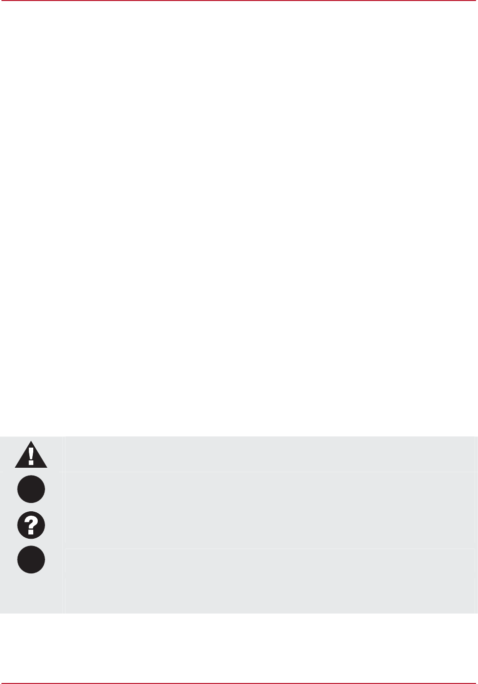
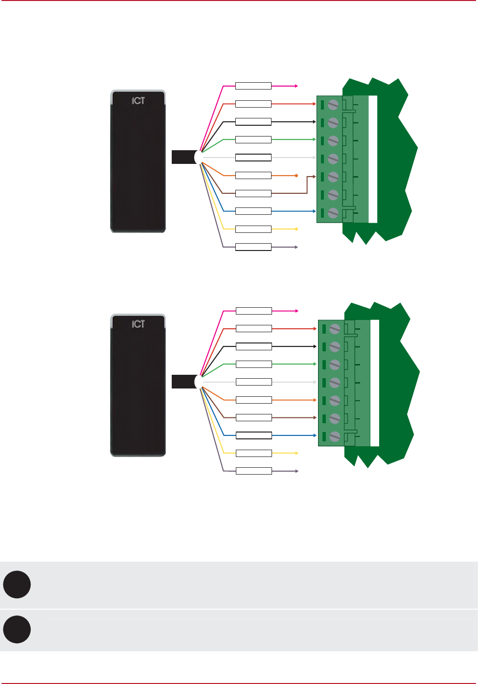
5 Wiegand Connection
When using the standard Wiegand Interface to the access controller or reader expander two wiring methods
can be used. Dual LED operation allows the signalling of both LEDs independently using the LED control lines
and is ideal to show the status of alarm or other integrated signals. Single LED allows a single LED line to control
both LED colors.
YELLOW
PURPLE
ORANGE
WHITE
RED
GREEN
BLACK
BROWN
BLUE
SHIELD
+12V
0V
DATA 0
DATA 1
GREEN LED
BLUE LED
BEEPER
NA
NB
+AUX- DO L2D1 L1 BZ
Single LED Connection (Default)
+AUX- DO L2D1 L1 BZ
YELLOW
PURPLE
ORANGE
WHITE
RED
GREEN
BLACK
BROWN
BLUE
SHIELD
+12V
0V
DATA 0
DATA 1
GREEN LED
BLUE LED
BEEPER
NA
NB
Dual LED Connection
Using the recommended cables as listed under the Technical Specifications, splice these cables together with
the pigtail of the reader and seal the splice. Route the cable from the reader to the host controller. Connect the
cables as shown in the diagrams above for either Dual LED Operation or Single LED Operation.
i
Connect the reader shield to a suitable earth point. DO NOT connect the shield to a ground or AUX
connection. DO NOT connect the shield wires together at the reader cable splice. With the shield wire
already terminated at the reader terminate the shield at the controller.
UL
ULC
Compatible access control card reader communication formats are: 26-, 34-, and 37-Bit Wiegand.
PRX-TSEC TSEC Multi-Technology Card Reader Installation Manual | May 2014 11
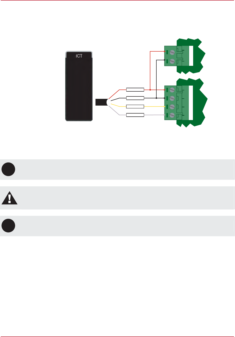
6 RS-485 Connection
Connection of an RS-485 Interface allows the TSEC Reader to communicate using an intelligent protocol or to
send data to an ASCII capable terminal. The connection diagram below shows the interface requirements. This
example shows a single reader connection however you can connect up to 32 devices. When connected in this
way, the other wires should not be connected to ground and be appropriately isolated.
AUX+ AUX- N+ N- NA NB
RS-485 USB
Convertor
PURPLE
YELLOW
BLACK
RED
RS-485 Interface
i
Connect the reader shield to a suitable earth point. DO NOT connect the shield to a ground or AUX
connection.
Warning: When connecting the Reader in RS-485 Mode you must isolate all unused wiring. DO NOT
terminate any unused connections to ground or a voltage or to another connection. Doing so may
damage the unit and will void any warranty.
UL
ULC
The RS-485 Connection has not been evaluated for UL/ULC installations.
12 PRX-TSEC TSEC Multi-Technology Card Reader Installation Manual | May 2014
7 Programming Interface
The TSEC Reader and Mifare series of readers utilize built in programming functions that allow many options to
be configured via a RS-485 Serial Interface. To program these options you must have a programming card.
These are marked with the text MF PROG CARD in place of the normal facility code and card number. A
Nano/Vario programming card will NOT work with the Mifare series of card readers. It is also possible to enter
the installer menu by shorting together brown and white wires when the reader is powered up.
7.1 Installer Programming
The reader can be configured to operate in a number of modes, have encryption keys configured and read
cards in various formats. To configure these options you enter program mode with the reader connected to a
RS-485 USB Converter (ACC-485-USB).
7.2 Entering Programming Mode
1. Complete the wiring connections as shown for using an RS-485 USB Converter (see page 11).
Ensure that the unconnected wires are not shorting to each other or any other connection point. You can
still configure the units if they are terminated to a reader interface you will require the +, - and NA, NB
connections to be connected to the RS-485 USB Converter.
2. Power up the card reader and RS-485 USB Converter.
3. Open Hyper Terminal or a similar serial terminal program, set the communications port to the RS-485 USB
Converter and set the parameters to 38400, N, 8, 1 and VT100 terminal emulation.
4. Make a short between the brown and white wires together and power up the reader. A configuration menu
will appear.
i
Data entry and the menu will time out after 40 seconds of no activity and restart the reader, any
programming changes will be lost.

PRX-TSEC TSEC Multi-Technology Card Reader Installation Manual | May 2014 13
8 Configuration
8.1 125KHz Reading Mode
Reading mode determines how the data on the 125KHz card will be processed by the Reader. The following
options are available by pressing the A key with the main menu displayed. To change the programmed reading
mode, press the A key and the available modes will toggle on the screen.
Setting Description
All Card Format All 125KHz cards will be read (no filtering)
ICT Can only read ICT programmed cards
POSTECH Can only read POSTECH programmed cards
HID Can only read HID programmed cards
ICT & HID Can only read ICT and HID programmed cards
ICT & POSTECH Can only read ICT and POSTECH programmed cards
POSTECH & HID Can only read POSTECH and HID programmed cards
Disable No 125KHz cards will be read
8.2 DESFire Reading Mode
Reading mode determines how the data on the DESFire card will be processed by the Reader. The following
options are available by pressing the B key with the main menu displayed. To change the programmed reading
mode press the B key and the available modes will toggle on the screen.
Setting Description
CSN Card serial number (CSN) or electronic serial number (ESN) reading converts the serial
number of the card to a site code and card number.
CSN Reverse Reverse card serial number reading converts the serial number of the card to a site code
and card number. The data sent is the binary reverse order of the CSN.
DESfire DESFire is the most secure reading mode. All card access is secured with a different
AES 128 bits encryption key. The ICT DESFire card data is also protected with another
AES 256 bit encryption key.
Disable No DESFire cards will be read.

14 PRX-TSEC TSEC Multi-Technology Card Reader Installation Manual | May 2014
8.3 Mifare Reading Mode
Reading mode determines how the data on the Mifare card will be processed by the Reader. The following
options are available by pressing the C key with the main menu displayed. To change the programmed reading
mode press the C key and the available modes will toggle on the screen.
Setting Description
CSN Card serial number (CSN) or electronic serial number (ESN) reading converts the serial
number of the card to a site code and card number.
CSN Reverse Reverse card serial number reading converts the serial number of the card to a site code
and card number. The data sent is the binary reverse order of the CSN.
Secured Mifare Secured Mifare provides medium protection access. This mode can read only ICT
Secured Mifare cards. Each card has a diversified access key and the data is protected
with a unique AES 256 bit encryption key.
ICT Card Setting the reading mode to ICT Card, allows the reader to read the standard Mifare ICT
cards.
Sector Sector based reading is used to read custom sector and allows the data from the Mifare
sector to be read and then converted to Wiegand data. Using ICT Mifare format cards,
custom key can also be used to increase the card security.
All This mode allows the reader to read Secured Mifare and ICT Card format.
Disable No Mifare cards will be read.
i
CSN and CSN Reverse modes of operation are not secure. The CSN and ESN numbers found in ISO
compliant RFID devices are transmitted without encryption and can be fraudulently generated. The
CSN modes are made available for legacy system compatibility and not recommended for new
installations.

PRX-TSEC TSEC Multi-Technology Card Reader Installation Manual | May 2014 15
8.4 Interface
The interface programming configures how the Reader sends information to the connected system. To change
the programmed reading mode press the D key and the available modes will toggle on the screen.
Note that Secured Mifare and Desfire cards send their code in the interface mode for which the card has been
programmed.
Setting Description
26 Bit Wiegand Standard 26 Bit Wiegand data sent on the D0 and D1 data lines. Truncation of
site/facility codes will occur for any card or tag programmed with a site code
above 255.
27 Bit Tecom Wiegand Tecom formatted 27 Bit Wiegand sent on the D0 and D1 data lines. Truncation of
site/facility codes will occur for any card or tag programmed with a site code
above 2048.
32 Bit Wiegand Standard 32 Bit Wiegand data sent on the D0 and D1 data lines. No truncation
will typically occur however it is recommended to use industry standard 34 Bit. 32
Bit Wiegand has no parity or other error checking.
34 Bit Wiegand Standard 34 Bit Wiegand data sent on the D0 and D1 data lines.
HOTEL Send card information in HOTEL format.
37 Bit Wiegand Standard 37 Bit Wiegand data sent on the D0 and D1 data lines.
64 Bit Wiegand Standard 64 Bit Wiegand data sent on the D0 and D1 data lines.
SERIAL ASCII RS-232 Serial data sent with communication port parameters set to 38400, N, 8,
1 and VT100 terminal emulation.
8.5 LED Function
The LED function allows the configuration of dual or single line led operation. The default is single LED mode. To
change the LED operation mode press the E key and the available modes will toggle on the screen.
8.6 Backlight
The backlight function allows the configuration of the backlight intensity. To change the backlight operation level
press the F key and the backlight display will change intensity levels.
8.7 Default Sector
When the Default Sector reading mode is selected, the sector number where the reader will read cards data can
be defined. It can be used with custom encryption keys. The default value is 14.
16 PRX-TSEC TSEC Multi-Technology Card Reader Installation Manual | May 2014
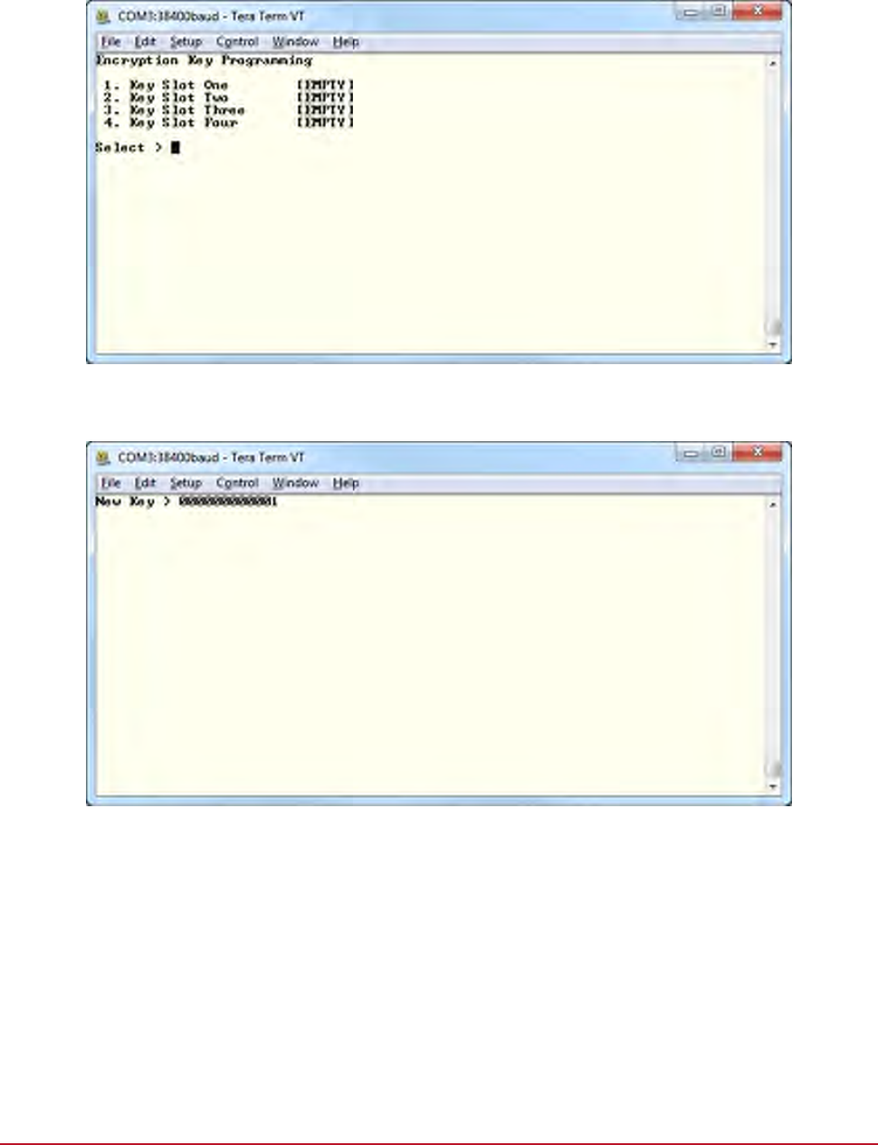
8.8 Encryption Keys
You are able to program custom keys in to the Reader by selecting the encryption option program the key
required in to the location that is available. You can delete encryption keys by programming a key location with
all FFFFFFFFFFFF however you are not able to view programmed keys.
To change the encryption keys select J from the menu, you will be shown the key selection screen below.
Select the key slot to program the key in to. Press ESC to cancel your entry.
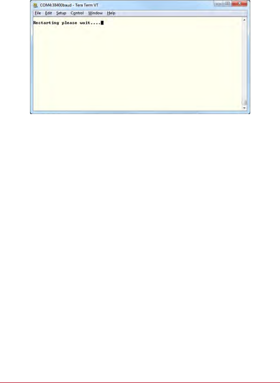
Once you have selected the desired key slot you will be prompted to enter the 6 byte hexadecimal encryption
key. This key cannot be read out of the reader and to erase a key program FFFFFFFFFFFFin to a key slot.
PRX-TSEC TSEC Multi-Technology Card Reader Installation Manual | May 2014 17
8.9 Save and Restart
You must select the Save and Restart option to save your programming changes and restart the device by
pressing the S key. Failing to select this option and powering the unit down will result in a loss of your
programming changes.
18 PRX-TSEC TSEC Multi-Technology Card Reader Installation Manual | May 2014
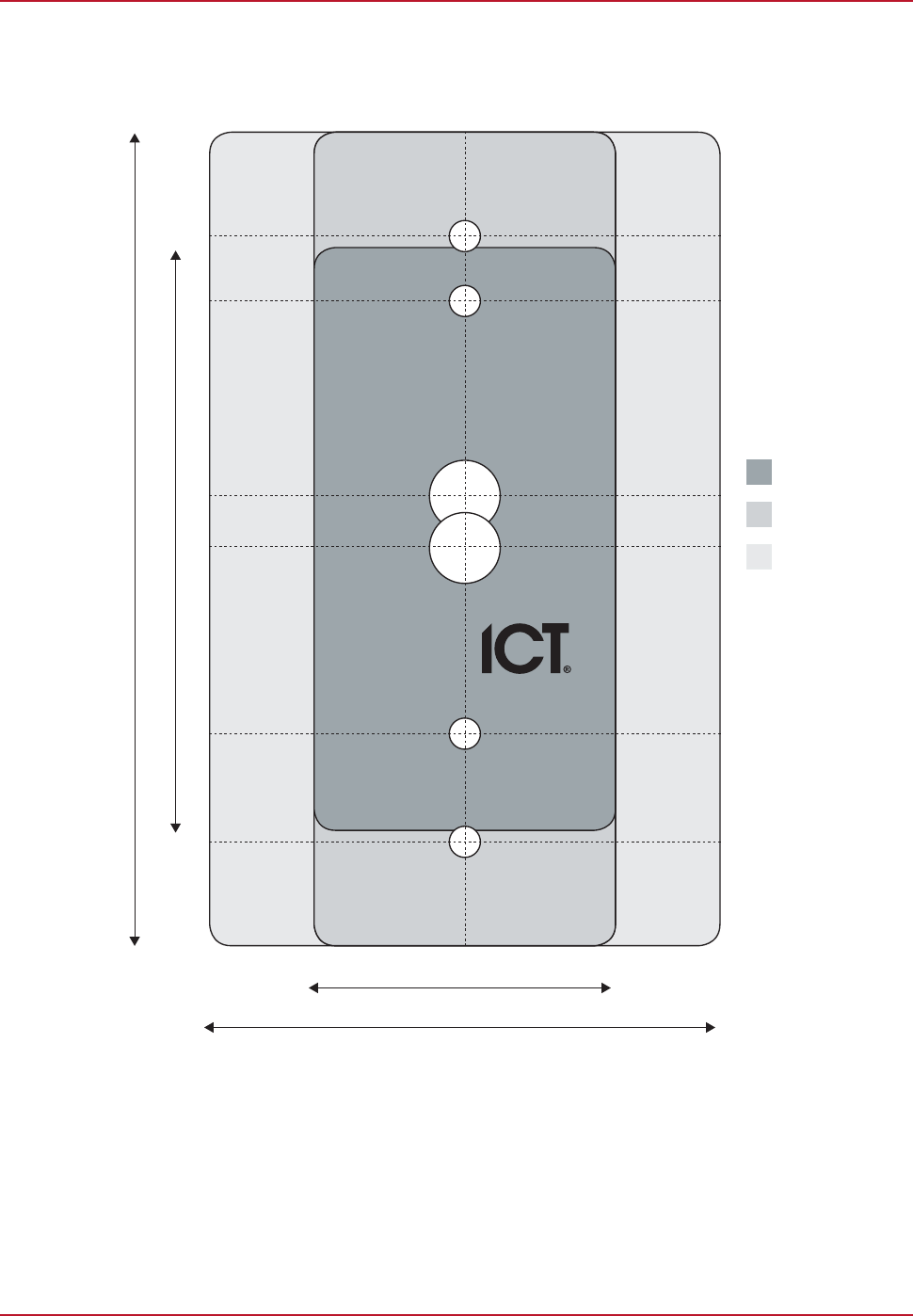
9 Technical Diagram
The dimensions shown below outline the essential details needed to help ensure the correct installation of the
TSEC Reader.
TSEC Mini
TSEC Standard
TSEC Extra
115mm / 4.53” (TSEC Standard/TSEC Extra)
84mm / 3.31” (TSEC Mini)
45mm / 1.77” (TSEC Standard/TSEC Mini)
73mm / 2.87” ( TSEC Extra)
4.5mm Screw Hole
4.5mm Screw Hole
10mm Cable Hole
10mm Cable Hole
4.5mm Screw Hole
4.5mm Screw Hole

PRX-TSEC TSEC Multi-Technology Card Reader Installation Manual | May 2014 19
10 Technical Specifications
The following technical specifications are important and vital to the correct operation of the TSEC Reader.
Failure to adhere to the specifications will result in any warranty or guarantee that was provided becoming null
and void.
Integrated Control Technology continually strives to increase the performance of its products. As a result these
specifications may change without notice. We recommend consulting the ICT website (http://www.ict.co) for the
latest documentation and product information.
Operating Voltage 12VDC (9.5 to 14VDC)
Operating Current Standard: 140mA (peak, reading)
Extra: 162mA (peak, reading)
Mini: 118mA (peak, reading)
Card Read Range Mifare 60mm (2.36")*
DESFire EV1 ISO 15mm (0.6")*
125kHz Clamshell 40mm (1.57”)
Tag Read Range Mifare 35mm (1.18")*
DESFire EV1 ISO 6mm (0.23")*
125kHz 25mm (0.98”)
Wiegand Interface Multiple format 26 or 34 Bit data 0 and data 1, card defined.
Max Cable Distance 150m (492ft)
Frequency 13.56 MHz ISO/IEC 14443 Type A*
125KHz pulse width modulated
Multi Conductor Cable 22Awg alpha 5196, 5198, 18Awg alpha 5386, 5388
Environment IP Rating IP65
Operating Temperature -35˚ to 65˚C (-31˚ to 149˚F)
Storage Temperature -10˚ to 85˚C (14˚ to 185˚F)
Dimensions (H x W x D) Standard: 115 x 45 x 18mm (4.53 x 1.77 x 0.71")
Extra: 115 x 73 x 18mm (4.53 x 2.87 x 0.71”)
Mini: 84 x 45 x 17mm (3.31 x 1.77 x 0.67”)
Weight Standard: 110g (3.89oz)
Extra: 155.8g (5.5oz)
Mini: 80g (2.82oz)
*Mifare/DESFire and Combo models only
The size of conductor used for the supply of power to the unit should be adequate to prevent voltage drop at
the terminals of no more than 5% of the rated supply voltage. Specifications are subject to change without
notice, please visit www.incontrol.co.nz for updated information.

20 PRX-TSEC TSEC Multi-Technology Card Reader Installation Manual | May 2014
11 UL and ULC Installation Requirements
i
Only UL / ULC listed compatible products are intended to be connected to a UL / ULC listed access
control system.
11.1 CAN/ULC-S319-05
This card reader is CAN/ULC-S319 Listed for Class I applications only.
Exit devices and wiring must be installed within the protected area.
The card reader must be connected with shielded, grounded cable.
Fail secure locking mechanism shall only be installed where allowed by the local authority having jurisdiction
(AHJ) and shall not impair the operation of panic hardware and emergency egress.
If fire resistance is required for door assembly, portal locking device(s) must be evaluated to ULC-S533 and
CAN/ULC-S104.
Must be installed with CAN/ULC-S319 Listed portal locking device(s) for ULC installations.
Input power must be supplied by a Class 2 or power limited device.
11.2 UL294
This card reader is UL 294 Listed for Class 1 applications only.
Exit devices and wiring must be installed within the protected area.
The card reader must be connected with shielded, grounded cable.
Fail secure locking mechanism shall only be installed where allowed by the local authority having jurisdiction
(AHJ) and shall not impair the operation of panic hardware and emergency egress.
If fire resistance is required for door assembly, portal locking device(s) must be evaluated to UL10B or
UL10C.
Must be installed with UL 1034 Listed electronic locks for UL installations.
Input power must be supplied by a Class 2 or power limited device.

PRX-TSEC TSEC Multi-Technology Card Reader Installation Manual | May 2014 21
12 FCC Compliance Statements
FCC PART 15, WARNINGS: INFORMATION TO USER
This equipment has been tested and found to comply with the limits for a Class A digital device, pursuant to
Part 15 of the FCC Rules. These limits are designed to provide reasonable protection against harmful
interference in a residential installation. This equipment generates, uses and can radiate radio frequency energy
and, if not installed and used in accordance with the instructions, may cause harmful interference to radio
communications. However, there is no guarantee that interference will not occur in a particular installation. If this
equipment does cause harmful interference to radio or television reception, which can be deter-mined by turning
the equipment off and on, the user is encouraged to try to correct the interference by one or more of the
following measures:
Re-orient the receiving antenna.
Increase the separation between the equipment and receiver.
Connect the equipment into an outlet on a circuit different from that to which the receiver is connected.
Changes or modifications not authorized by the party responsible for compliance could void the user's
authority to operate this product.
This device complies with Part 15 of the FCC rules.
Operation is subject to the following two conditions:
This device may not cause harmful interference.
This device must accept any interference received, including interference that may cause undesired
operation.
NOTE: THE GRANTEE IS NOT RESPONSIBLE FOR ANY CHANGES OR MODIFICATIONS NOT EXPRESSLY
APPROVED BY THE PARTY RESPONSIBLE FOR COMPLIANCE. SUCH MODIFICATIONS COULD VOID THE
USER’S AUTHORITY TO OPERATE THE EQUIPMENT.

22 PRX-TSEC TSEC Multi-Technology Card Reader Installation Manual | May 2014
13 Industry Canada Statement
This class A digital apparatus complies with Canadian ICES-003.
Cet appareil numérique de la classe A est conforme à la norme NMB-003 du Canada.

PRX-TSEC TSEC Multi-Technology Card Reader Installation Manual | May 2014 23
14 Ordering Information
Please use the following product codes when placing an order from the TSEC Card Reader range.
Standard Range:
PRX-TSEC-STD - TSEC Standard Card Reader
PRX-TSEC-STD-KP - TSEC Standard Card Reader with Keypad
PRX-TSEC-STD-125 - TSEC Standard 125KHz Card Reader
PRX-TSEC-STD-125-KP - TSEC Standard 125KHz Card Reader with Keypad
PRX-TSEC-STD-DF - TSEC Standard DESFire Card Reader
PRX-TSEC-STD-DF-KP - TSEC Standard DESFire Card Reader with Keypad
Extra Range:
PRX-TSEC-EXTRA - TSEC Extra Card Reader
PRX-TSEC-EXTRA-KP - TSEC Extra Card Reader with Keypad
PRX-TSEC-EXTRA-125 - TSEC Extra 125KHz Card Reader
PRX-TSEC-EXTRA-125-KP - TSEC Extra 125KHz Card Reader with Keypad
PRX-TSEC-EXTRA-DF - TSEC Extra DESFire Card Reader
PRX-TSEC-EXTRA-DF-KP - TSEC Extra DESFire Card Reader with Keypad
Mini Range:
PRX-TSEC-MINI - TSEC Mini Card Reader
PRX-TSEC-MINI-125 - TSEC Mini 125KHz Card Reader
PRX-TSEC-MINI-DF - TSEC Mini DESFire Card Reader
Manuals and additional literature are available on the ICT Website (http://www.incontrol.co.nz) under the
Support section.

24 PRX-TSEC TSEC Multi-Technology Card Reader Installation Manual | May 2014
15 Warranty
Integrated Control Technology (ICT) warrants its products to be free from defects in materials and workmanship
under normal use for a period of two years. Except as specifically stated herein, all express or implied warranties
whatsoever, statutory or otherwise, including without limitation, any implied warranty of merchantability and
fitness for a particular purpose, are expressly excluded. ICT does not install or connect the products and
because the products may be used in conjunction with products not manufactured by ICT, ICT cannot
guarantee the performance of the security system. ICT's obligation and liability under this warranty is expressly
limited to repairing or replacing, at ICT's option, any product not meeting the specifications. In no event shall ICT
be liable to the buyer or any other person for any loss or damages whether direct or indirect or consequential or
incidental, including without limitation, any damages for lost profits, stolen goods, or claims by any other party
caused by defective goods or otherwise arising from the improper, incorrect or otherwise faulty installation or
use of the merchandise sold.

PRX-TSEC TSEC Multi-Technology Card Reader Installation Manual | May 2014 25
16 Contact
Integrated Control Technology welcomes all feedback.
Please visit our website (http://www.ict.co) or use the contact information below.
Integrated Control Technology
P.O. Box 302-340
North Harbour Post Centre
Auckland
New Zealand
11 Canaveral Drive
Albany
North Shore City 0632
Auckland
New Zealand
Phone: +64-9-476-7124
Toll Free Numbers:
0800 ICT 111 (0800 428 111) - New Zealand
1800 ICT 111 (1800 428 111) - Australia
1855 ICT 9111 (1855 428 9111) - USA/Canada
Email: sales@incontrol.co.nz or support@incontrol.co.nz
Web: www.ict.co

Disclaimer: Whilst every effort has been made to ensure accuracy in the representation of this product, neither
Integrated Control Technology Ltd nor its employees, shall be liable under any circumstances to any party in respect
of decisions or actions they may make as a result of using this information. In accordance with the Integrated Control
Technology policy of enhanced development, design and specifications are subject to chnage without notice.
227-4310-000 : UL 26-July-2013