Integrated Microwave Technologies 23UHPA-P10 Amplifier User Manual
Integrated Microwave Technologies, LLC. Amplifier
User manual
Nucomm Inc.
101 Bilby Road
Hackettstown, NJ 07840
Tel: 908-852-3700 Fax: 908-813-0399
www.Nucomm.com
TRUCK PACKAGE
FOR
CHANNELMASTER TX1
~ PS18 Control Drawer and High Power Amplifier(s) ~
User Manual
NUCOMM PUBLICATION: M03-0008-00A – REV 0.1

Revision 0.1
ChannelMaster Truck Package (PS18 & HPA/UHPA) 2
FCC STATEMENT
This equipment has been tested and found to comply with Part 74.637 (a) (2) of the FCC Rules
and Regulations. Any unauthorized changes or modifications not expressly approved by
Nucomm, Inc. could void the user’s authority to operate the equipment, and invalidate the
equipment’s warranty.
RF Exposure Warning
This equipment complies with FCC radiation exposure limits
set forth for an uncontrolled environment.
End users must follow the specific operating instructions
for satisfying RF exposure compliance.
The antenna(s) used for this transmitter must be installed to provide a
separation distance of at least 20 cm from all persons, and must not be co- located
or operating in
conju
nction with any other antenna or transmitter.
CAUTION!
RISK OF ELECTRICAL SHOCK. DO NOT REMOVE COVERS.
Do not remove any covers.
Refer servicing to qualified technicians only.
Disconnect all power before servicing.
Read and perform all instructions carefully.
Failure to follow suggested instructions and guidelines may void all warranties.
Document Revision
Date Modified Revision Modified by Modification Detail
March 29, 2007
September 25, 2008
0.0
0.1
M Hardy /
L Ramirez
M Hardy
Initial release
Added RF Warning

Revision 0.1
3 ChannelMaster Truck Package (PS18 & HPA/UHPA)
TABLE of CONTENTS
Warranty ................................................................................................................................................................................ 4
Shipping Damage .................................................................................................................................................................. 4
Customer Service Information.............................................................................................................................................. 4
Telephone Consultation................................................................................................................................................... 4
Field Repair ..................................................................................................................................................................... 5
Replacement Module ....................................................................................................................................................... 5
Equipment Returns........................................................................................................................................................... 5
International Returns....................................................................................................................................................... 5
Unit Identification............................................................................................................................................................ 6
1.0 DESCRIPTION & FEATURES .............................................................................................................................. 7
1.1. Control Drawer ......................................................................................................................................................... 9
1.2. High Power Amplifier (“HPA”)............................................................................................................................. 10
2.0 SPECIFICATIONS ................................................................................................................................................ 13
3.0 INSTALLATION .............................................................................. ERROR! BOOKMARK NOT DEFINED.
3.1. Cable & NYCOIL Planning ................................................................................................................................... 15
3.2. Control Drawer Install ............................................................................................................................................ 15
3.3. Mast Mounted HPA Mechanical Install................................................................................................................. 19
3.4. Mast Mounted HPA Electrical Install .................................................................................................................... 20
4.0 OPERATION.......................................................................................................................................................... 23
4.1. Control Drawer Front Panel ................................................................................................................................... 23
4.2. Control Unit Section ............................................................................................................................................... 24
4.3. Antenna Section...................................................................................................................................................... 24
4.4. Power Section ......................................................................................................................................................... 24
TABLE of FIGURES
FIGURE 1-1: SINGLE BAND TRUCK PACKAGE BLOCK DIAGRAM ...................................................................... 8
FIGURE 1-2: DUAL BAND TRUCK PACKAGE BLOCK DIAGRAM ......................................................................... 8
FIGURE 1-3: TRUCK PACKAGE CONTROL DRAWER (FRONT, SHOWN WITH CHANNELMASTER) ........... 9
FIGURE 1-4: TRUCK PACKAGE CONTROL DRAWER (REAR, SHOWN WITH CHANNELMASTER).............. 9
FIGURE 1-5: MAST MOUNTED POWER AMP, STANDARD POWER (FRONT) ................................................... 10
FIGURE 1-6: MAST MOUNTED POWER AMP, STANDARD POWER (REAR)...................................................... 10
FIGURE 1-7: RF MAST MOUNTED POWER AMP, ULTRA HIGH POWER............................................................ 11
FIGURE 3-1: CONTROL DRAWER................................................................................................................................ 15
FIGURE 3-2: RAIL ASSEMBLY...................................................................................................................................... 15
FIGURE 3-3: CONTROL DRAWER MOUNTED IN RAIL ASSEMBLY.................................................................... 15
FIGURE 3-4: MOUNTING BRACKET DETAIL............................................................................................................ 16
FIGURE 3-5: INSTALLING THE MOUNTING BRACKETS....................................................................................... 16
FIGURE 3-6: LOCKING THE MOUNTING BRACKETS............................................................................................. 17
FIGURE 3-7: CONNECTING POWER SOURCE TO CHANNELMASTER ............................................................... 17
FIGURE 3-8: CONNECTING CABLE TO CHANNELMASTER RF OUTPUT.......................................................... 18
FIGURE 3-9: HPA’S MOUNTING ON PAN & TILT (SINGLE-BAND)...................................................................... 19
FIGURE 3-10: HPA’S MOUNTING ON PAN & TILT (DUAL-BAND)....................................................................... 19
FIGURE 3-11: RF HEAD CONNECTIONS (IF& ANTENNA POLARIZATION) ...................................................... 22
FIGURE 3-12: RF HEAD CONNECTIONS (RF TO ANTENNA)................................................................................. 22

Revision 0.1
ChannelMaster Truck Package (PS18 & HPA/UHPA) 4
Warranty
Equipment manufactured by Nucomm, Inc. is warranted to meet all specifications and to be free
from defects in material and workmanship within a period of two years from date of shipment
from Nucomm. The company’s liability under this warranty is limited to:
Servicing or adjusting equipment.
Replacement of defective parts.
Any equipment returned to the factory shall have the freight paid for by the buyer.
Equipment showing damage by misuse, abnormal conditions of operation, or attempts to repair
by other than authorized service personal shall be excluded from this warranty. Nucomm, Inc.
shall in no event be responsible for incidental injury or property damage. Since Nucomm, Inc.
has no control over conditions of use, no warranty is made or implied as to suitability for the
customer’s intended use, beyond such performance specifications as are made part of the
purchase order. There are no warranties expressed or implied, except as stated herein. This
limitation on warranties shall not be modified by verbal representations.
Shipping Damage
Equipment shipped FOB Nucomm, Inc.; shall become the property of buyer upon delivery to and
receipt from carrier. Any damage in shipment should be handled by the buyer directly with the
carrier. Immediately request the carrier’s inspection upon evidence of damage in shipment.
Customer Service Information
Customer Service technicians at Nucomm are available to extend technical assistance to customers
installing or operating Nucomm equipment. They will also assist customers with equipment
troubleshooting. If this cannot be successfully accomplished by telephone, the equipment may be
returned to the factory for repair. Loaner equipment is often available until Nucomm is able to ship
repaired units. Nucomm evaluates all returned units and then confers with customers on corrective
action. If no corrective action is taken, or required, a diagnostic fee may be charged.
Telephone Consultation
Should there be a need for emergency telephone consultation, please have your model number and
serial number available for the Customer Service representative. Nucomm Customer Service
representatives are available to deal with all technical questions or difficulties.
Telephone:
During Nucomm business hours, 8:30am – 5:30pm EST (-5:00 GMT):
US: ................................................................................(908) 852-3700
International:.................................................................001 - 1 - (908) 852-3700
24-Hour Hotline:
US: ................................................................................(888) 531-3892
International:.................................................................001 - 1 - (888) 531-3892

Revision 0.1
5 ChannelMaster Truck Package (PS18 & HPA/UHPA)
Field Repair
Nucomm products are designed with easy access to components to facilitate service. When
troubleshooting, the user is cautioned to read all module descriptions in this manual. Some
Nucomm modules cannot be serviced in the field. Warnings are included in the circuit descriptions
and on certain modules themselves, however the lack of a warning cannot be construed as a
statement of safety. To prevent voiding of the Nucomm warranty that protects the equipment,
please contact Nucomm before servicing or making any repairs.
Replacement Module
Troubleshooting to the component level is often not cost-effective and frequently impossible.
Often the practical method of effecting field repairs is to substitute known good spare modules for
suspect units. Nucomm maintains an inventory of replacement modules for its standard line of
products.
Equipment Returns
Do not return any Nucomm product to the factory until you have received a return materials
authorization (RMA) number and shipping instructions from Nucomm. When returning equipment
to Nucomm, please encolse a letter containing the following:
• RMA number.
• Model number.
• Serial number.
• Frequency operating range (in case of modules).
• A detailed description of the problem.
• Name of engineer or technician we may contact in regards to this problem.
• Include a “ship to” and “bill to” address.
Ship ALL RETURNS to:
Nucomm, Inc.
Attn: RMA
101 Bilby Road
Hackettstown, New Jersey 07840
International Returns
In the case of units being shipped from outside the United States, Nucomm recommends the use of
a courier such as Federal Express, UPS, etc., and that the goods be shipped DOOR-TO-DOOR
PRE-PAID. This will eliminate Customs costs, handling charges and delays. Enclose all the
information above, plus a statement that the equipment was manufactured in the United States (the
latter is needed to expedite customs processing).

Revision 0.1
ChannelMaster Truck Package (PS18 & HPA/UHPA) 6
Unit Identification
Given the model number, the unit configuration can be determined using the following:
AAAAA – CMTP– BB
Power Output
Model
Generalized Frequency Band Designator
Where:
AAAAA = mean frequency band center in GHz rounded to the closest GHz. This number is then
multiplied by 10. For multiple bands, each center frequency designation is separated by a
backslash "/".
BB = Used to identify the power output, per the following Power Output Designators:
Power Output is represented by Letters (A-Z; A=1, B=2, C=3, etc) for the analog power, and
Numbers (0-9) for the digital power. For example, a 5W Analog / 2W digital system would be
described with a power indicator of "E2". A Dual-Band system would have two sets of power
indicators, to show the power levels at both bands.
Proprietary & Disclaimer Notice
All information and graphic images herein contained within this manual are considered the sole
property of Nucomm, Inc. and are issued in the strictest of confidence. This material may not be
reproduced, stored, copied, or converted in any form, nor shall it be disclosed to others or used
for manufacturing or any other purpose without the written permission of an authorized
representative of Nucomm, Inc.
Nucomm, Inc. has made every effort to ensure the accuracy of this material at the time of printing.
However, as the specifications, equipment, and this manual are subject to change without notice,
Nucomm, Inc. assumes no responsibility or liability whatsoever for any errors or inaccuracies that
may appear in this manual, or for any decisions based on its use. This manual is supplied for
informational purposes only and should not be construed as a commitment by Nucomm, Inc.
© Copyrighted 2007, Nucomm, Inc., Hackettstown, New Jersey 07840

Revision 0.1
7 ChannelMaster Truck Package (PS18 & HPA/UHPA)
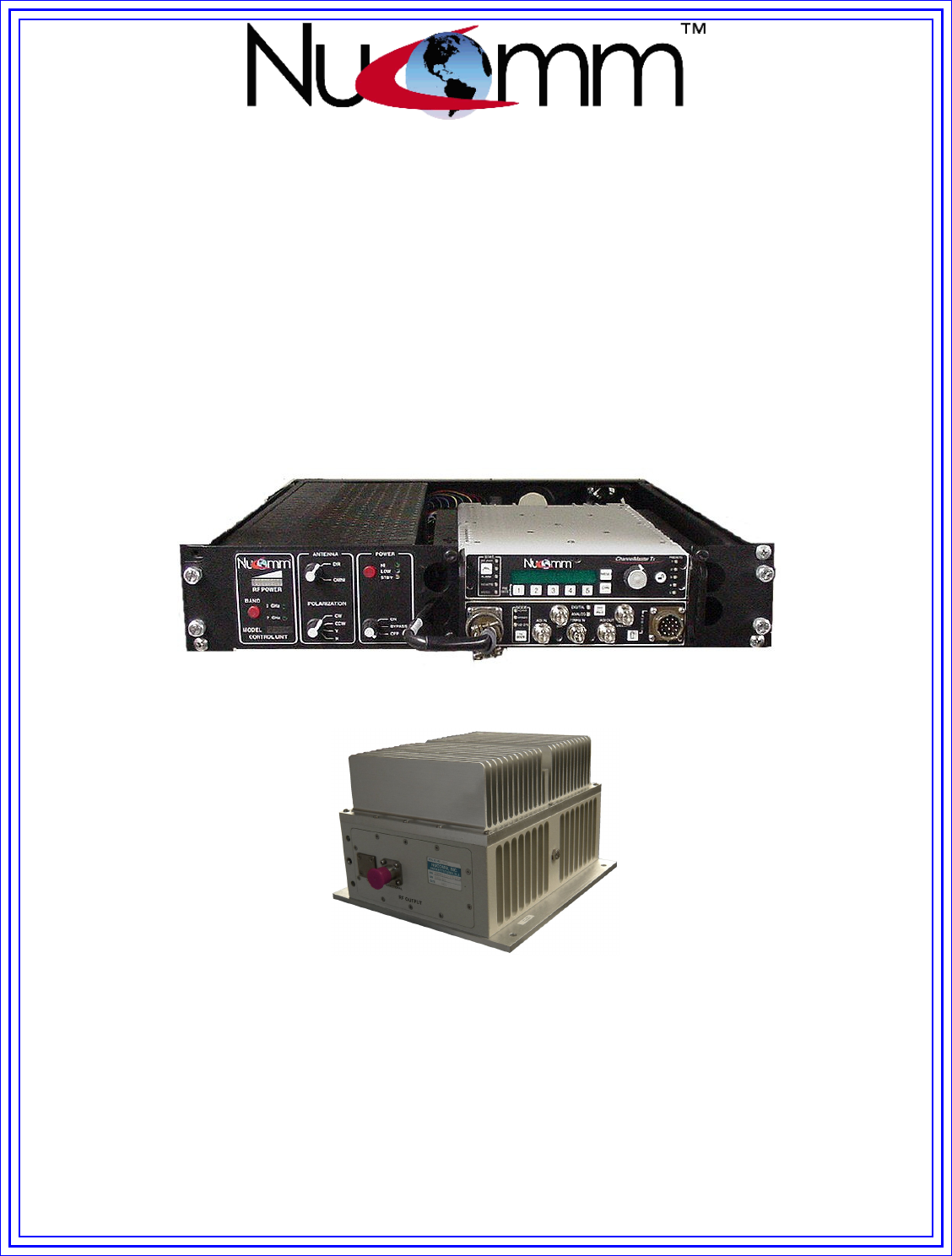
1.0 DESCRIPTION & FEATURES
Nucomm’s optional TruckMount Package (aka “Truck Package”) for the ChannelMaster TX1
provides ENG/OB truck operators the flexibility to use the ChannelMaster TX1 as a full-featured
truck transmitter, while retaining the ability to easily remove the transmitter for portable use as
required.
The TruckMount Package can be configured for Single or Dual-Band operation, and includes
High Power Mast Mounted Amplifier(s) (HPA’s) to increase the range of the base
ChannelMaster transmitter. The Block Diagrams in Figure 1-1 and Figure 1-2 show the available
Single and Dual Band configurations.
The Single Band TruckMount Package consists of a 2RU* “nested docking station” style Control
Drawer which accepts the ChannelMaster portable, and a Mast-Mounted HPA which is typically
attached to the side of the Pan & Tilt, at the top of a telescoping mast, with a Nucomm mounting
plate. The Control Drawer and Mast-mounted HPA are interconnected via SF-214 RF that is
typically installed in a NYCOIL assembly for carriage up the mast.
The Dual Band TruckMount Package consists of a 2RU* “nested docking station” style Control
Drawer which accepts the ChannelMaster portable, and two Mast-Mounted HPA’s which are
typically attached to the sides of the Pan & Tilt, at the top of a telescoping mast, with Nucomm
mounting plates. The Control Drawer and Mast-mounted HPA’s are interconnected via a single
SF-214 RF that is typically installed in a NYCOIL assembly for carriage up the mast. In the case
of the Dual Band system, the cable from the Control Drawer is first attached to the 7 or 13GHz
amplifier, and then routed over to the 2 GHz amplifier.
*Note: Depending on the RF power output level of the ChannelMaster portable transmitter, the
overall height of the docked transmitter and Control Drawer may exceed 2RU due to the heat
sink fins integrated into the top of the ChannelMaster portable.
All signals required at the amplifier (RF, Control and Power) are diplexed onto the SF214.
The standard AC power supply for the TruckMount Package Control Drawer has an operating
range from 90 to 240 VAC (40 to 60Hz). Optionally, a +11 to +32 VDC power supply, or a
Universal Power Supply can be factory installed. The Universal Power Supply operates on 90 to
240 VAC (40 to 60Hz), or +11 to +32 VDC.
Revision 0.1
ChannelMaster Truck Package (PS18 & HPA/UHPA) 8
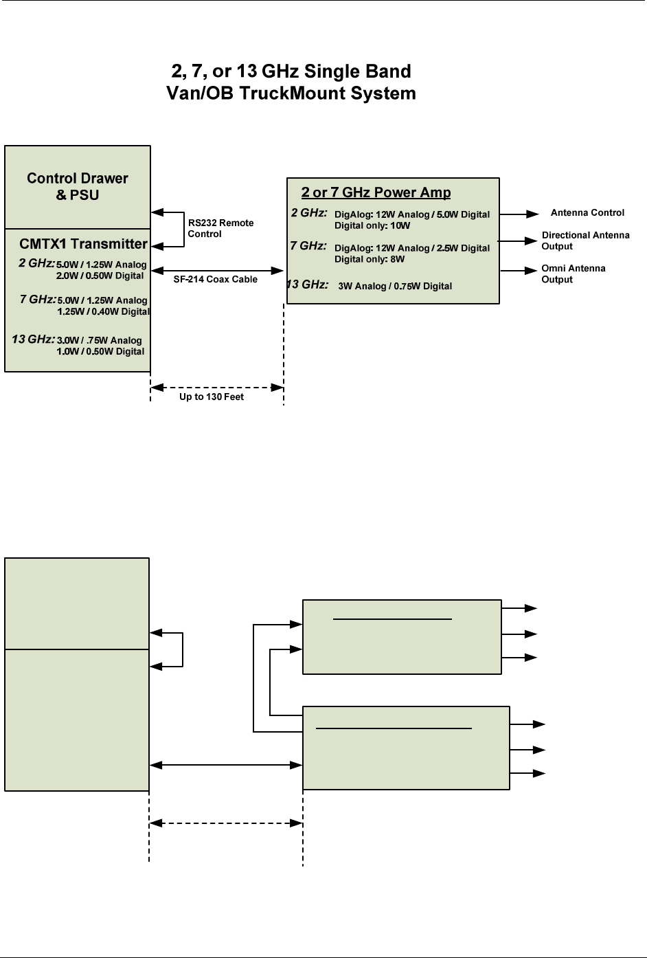
Figure 1-1: Single Band Truck Package Block Diagram
2, and 7 or 13 GHz Dual Band
Van/OB TruckMount System
Control Drawer
& PSU
CMTX1 Transmitter
2 GHz:
7 GHz:
5.0W / 1.25W Analog
2.0W / 0.50W Digital
5.0W / 1.25W Analog
1.25W / 0.40W Digital
2 GHz Power Amp
2 GHz: 12W Analog / 3.0W Digital
(or 10W Digital)
SF-214 Coax Cable
RS232
Remote
Control
Up to 130 Feet
Directional Antenna
Output
Omni Antenna
Output
13 GHz: 3.0W / .75W Analog
1.0W / 0.50W Digital
7 or 13 GHz Power Amp
7 GHz: DigAlog: 10W Analog / 2.5W Digital
Digital only: 8W
13 GHz: 3W Analog / 0.75W Digital
Multi-Conductor Cable
SF-214 Coax
Cable Antenna Control
Directional Antenna
Output
Omni Antenna
Output
Antenna Control
Figure 1-2: Dual Band Truck Package Block Diagram
Revision 0.1
9 ChannelMaster Truck Package (PS18 & HPA/UHPA)
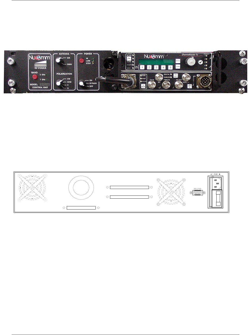
1.1. Control Drawer
The Truck Package Control Drawer (depicted in Figures 1-3 & 1-4), provides controls for the High
Power Amplifier(s), as well as various antenna parameters. The functions are fully described in the
Operations section of this manual.
Figure 1-3: Truck Package Control Drawer (front, shown with ChannelMaster)
Figure 1-4: Truck Package Control Drawer (rear, shown with ChannelMaster)
Revision 0.1
ChannelMaster Truck Package (PS18 & HPA/UHPA) 10
IF INTERFACE POLARIZATION
ANTENNA
RF OUTPUT
OMNI DIRECTIONAL
2GHz
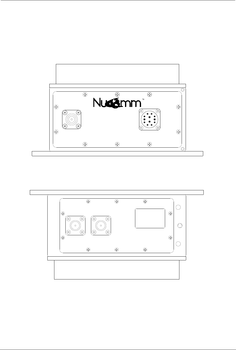
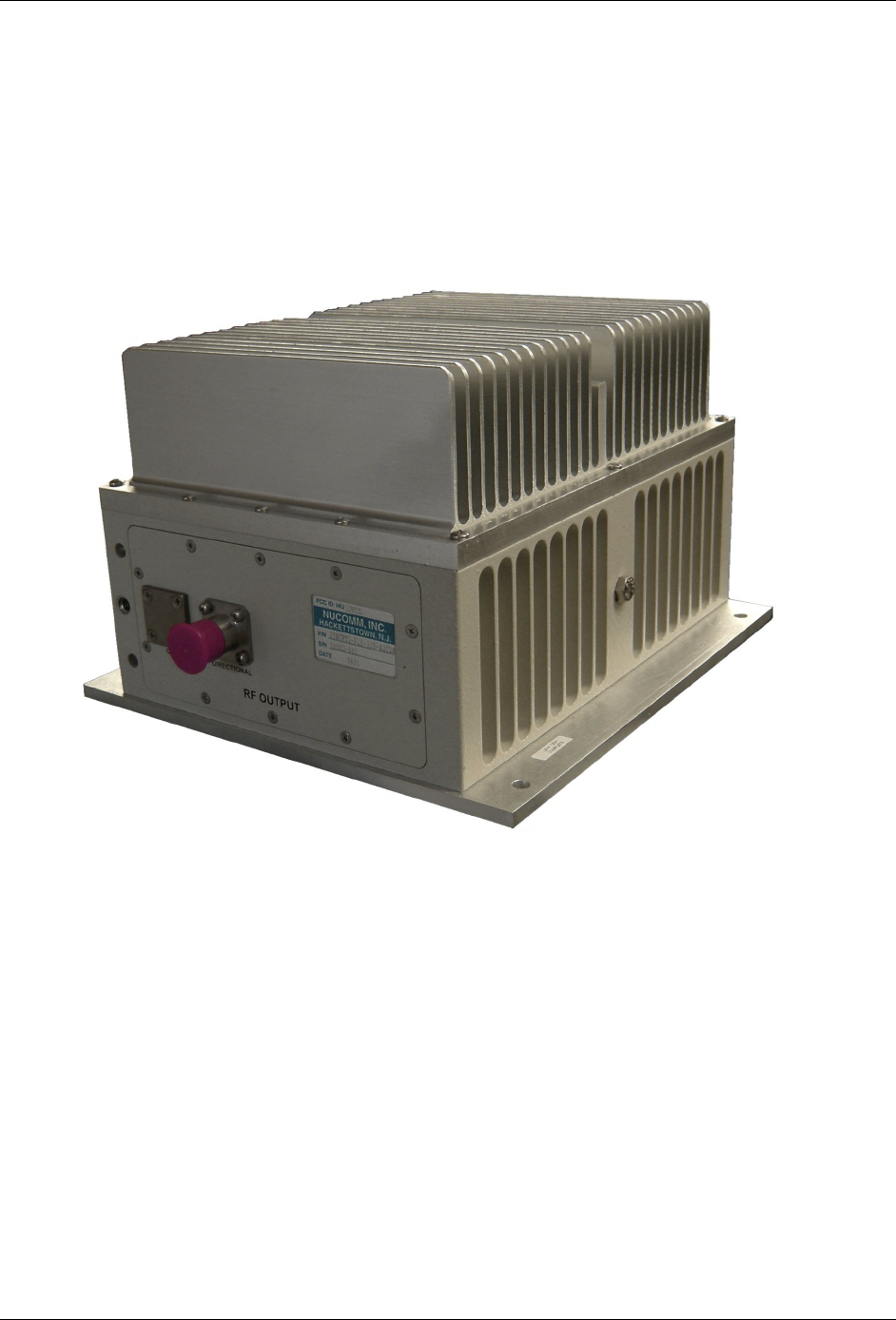
1.2. High Power Amplifier (“HPA”)
The Truck Package High Power Amplifier, or “HPA”, (depicted in Figures 1-5 & 1-6) has
connectors for the diplexed RF, Power & Control from the Control Drawer, and RF out to the
transmit antenna. For Dual-Band systems, in order to minimize NYCOIL cabling requirements,
one HPA is designated as “Amp #1” and is configured to accept all signals from the Control
Drawer, and route them to Amp #2.
Figure 1-5: Mast Mounted Power Amp, Standard Power (Front)
Figure 1-6: Mast Mounted Power Amp, Standard Power (Rear)
Revision 0.1
11 ChannelMaster Truck Package (PS18 & HPA/UHPA)
Figure 1-7: RF Mast Mounted Power Amp, Ultra High Power

Revision 0.1
ChannelMaster Truck Package (PS18 & HPA/UHPA) 12

Revision 0.1
13 ChannelMaster Truck Package (PS18 & HPA/UHPA)
2.0 SPECIFICATIONS
RF Performance:
Frequency Bands:.................................... bands from 1.9GHz to 13.25GHz available
(higher frequencies pending). Multi-band models available. Please contact Nucomm for
specifics.
Power Output (for the base ChannelMaster Transmitter)
Power Mode:
Standby: ............................................ ......................No RF output
HI Power: ........................................... ......................Full power
LOW Power: ...................................... ......................~6dB down from full power
Low Power Transmitters:
2 GHz Analog High Power Mode ....... ......................5.0 Watts
2 GHz Digital High Power Mode ........ ......................2.0 Watts
7 GHz Analog High Power Mode ....... ......................5.0 Watts
7 GHz Digital High Power Mode ........ ......................1.25 Watts
13GHz Analog High Power Mode ...... ......................TBD
13 GHz Digital High Power Mode ...... ......................TBD
Medium Power Transmitters:
2 GHz Analog High Power Mode ....... ......................12.0 Watts
2 GHz Digital High Power Mode ........ ......................4.0 Watts
7 GHz Analog High Power Mode ....... ......................5.0 Watts
7 GHz Digital High Power Mode ........ ......................1.25 Watts
13 GHz Analog High Power Mode .... ......................TBD
13 GHz Digital High Power Mode ...... ......................TBD
Remote Control:
When the ChannelMaster portable is in the 2RU Control Drawer, the drawer controls the
ChannelMaster via RS232 lines out of the ChannelMaster front panel power connector.
Power Requirements:............................ AC 90 to 240 VAC or +11 to +32 VDC.
Environmental:
Temperature range:
Full specification:................................ -30° to +60°C
Storage: ............................................. -40° to +80°C
Humidity: ................................................. 0 to 95% non-condensing

Revision 0.1
ChannelMaster Truck Package (PS18 & HPA/UHPA) 14
Physical Characteristics:
Control Drawer (without transmitter):
Size: ......................................................... 2RU x 19” (48.26cm)
Weight:..................................................... 12.0 lbs (5.45kg)
Mast Mounted High Power Amplifier(s):
Size (housing only): ................................. 9.78”(251mm) x 9.125”(231mm) x 5”(125mm)
Size (with connectors):............................. 11.375”(290mm) x 9.125”(231mm) x 5”(125mm)
Weight: .................................................... 11.75 lbs (5.34kg)
Mast Mounted Ultra High Power Amplifier(s):
Size (housing only): ............................9.78”(251mm) x 9.125”(231mm) x 6.25”(158mm)
Size (with connectors):........................11.375”(290mm) x 9.125”(231mm) x 6.25”(158mm)
Weight: ...............................................14.00 lbs (6.36kg)
Connectors:
RF Input/Output: ...................................... Type “N” female
Audio:....................................................... XLR
Remote Control: ...................................... not applicable
All Amplifier Cases:............................... Weather-proofed
Revision 0.1
15 ChannelMaster Truck Package (PS18 & HPA/UHPA)
3.0 INSTALLATION
3.1. Cable & NYCOIL Planning
The only NYCOIL cable required for the Mast Mounted Amplifier(s) is a single SF214, coaxial cable. Pan &
Tilt requirements are not addressed in this manual.
3.2. Control Drawer Install
3.2.1 Gather all components, parts list, and drawing to be used in the assembly of the Control Drawer
(Figure 3-1) for the ChannelMaster with HPA. Ensure that all components match the documentation.
Figure 3-1: Control Drawer
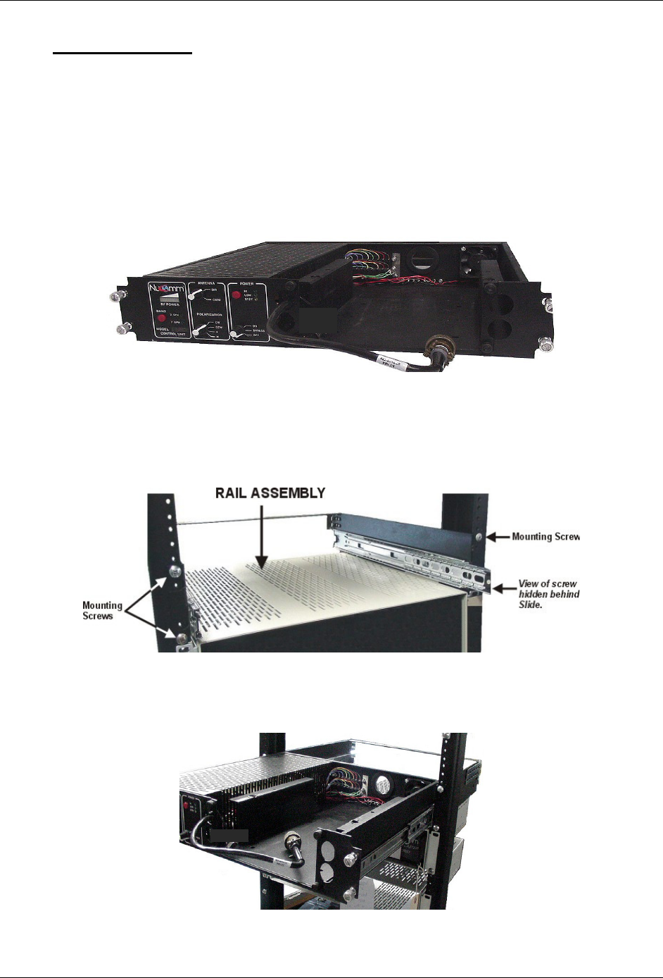
3.2.2 Install Rail Assembly on to rack. Ensure that the assembly is flush against the rack and level. Next
fasten the four mounting screws and tighten firmly. (Refer to Figure 3-2.)
Figure 3-2: Rail Assembly
3.2.3 Slide the Control Drawer into the Rail Assembly until you hear each side “click” (Refer to Figure 3-
3).
Figure 3-3: Control Drawer Mounted in Rail Assembly
Revision 0.1
ChannelMaster Truck Package (PS18 & HPA/UHPA) 16
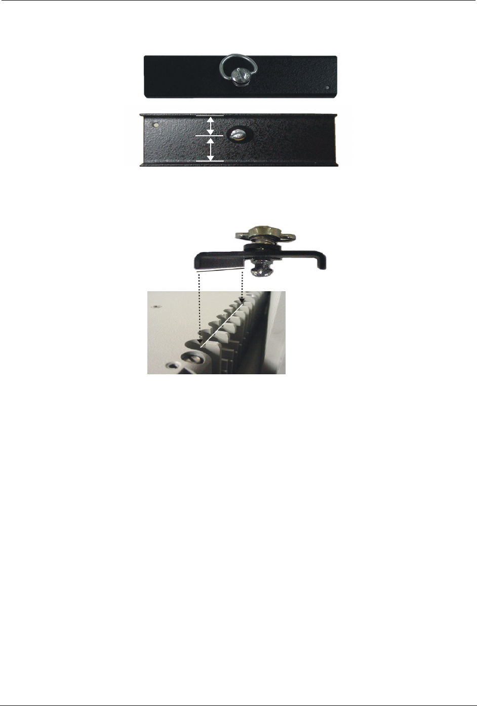
3.2.4 Slide the ChannelMaster into the Control Drawer. Retrieve the two mounting brackets (see Figure
3-4). (Note: On later versions, the bracket is integrated into the housing.)
Mounting Brackets
Longer
Shorter
Figure 3-4: Mounting Bracket detail
3.2.5 Properly orient the bracket (bracket mounts only one way) and insert one edge of the bracket into
the grooves (on one side of the ChannelMaster), ensuring that the bracket’s fastener aligns with its
associated mounting hole. (Refer to Figure 3-5.)
Figure 3-5: Installing the Mounting Brackets
Revision 0.1
17 ChannelMaster Truck Package (PS18 & HPA/UHPA)
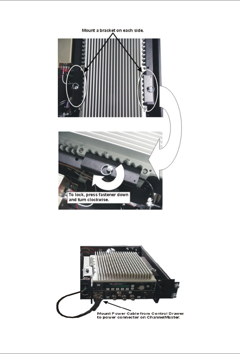
3.2.6 Lock bracket into place by pressing down on fastener and turning it clockwise. Repeat process for
other side of ChannelMaster. (Refer to Figure 3-6.)
Figure 3-6: Locking the Mounting Brackets
3.2.7 Connect the Power and Audio Cables from front of Control Drawer to Power and Audio Connectors
on the ChannelMaster. (Refer to Figure 3-7. Audio not shown).
Figure 3-7: Connecting Power Source to ChannelMaster
Revision 0.1
ChannelMaster Truck Package (PS18 & HPA/UHPA) 18
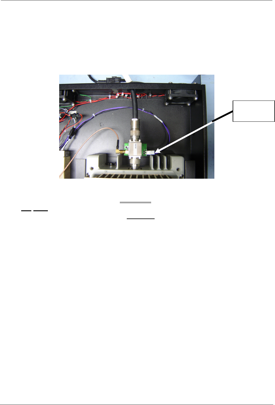
3.2.8 Diplexer Option Installation - Install Diplexer on RF output connector of ChannelMaster (N type
Connector). Attach RF cable from Nycoil to output of Diplexer (N type connector). (Refer to Figure
3-8). (The Diplexer is used to combine the +24 power and control signals onto the RF Coax Center
Conductor).
On later versions this step requires lifting up of the integrated fan housing, which may require the
drawer assembly to be pulled forward from the rack on the mounting rails.
Figure 3-8: Connecting Cable to ChannelMaster RF Output
CAUTION!
DO NOT measure RF power with a Power Meter inserted in the RF + DC
path of the coxial cable UNLESS the power connector
(with purple and black wires) shown above has been disconnected.
Power
Connector
Revision 0.1
19 ChannelMaster Truck Package (PS18 & HPA/UHPA)
IF INTERFACE POLARIZATION
ANTENNA
IF INTERFACE POLARIZATION
ANTENNA
IF INTERFACE
POLARIZATION
ANTENNA
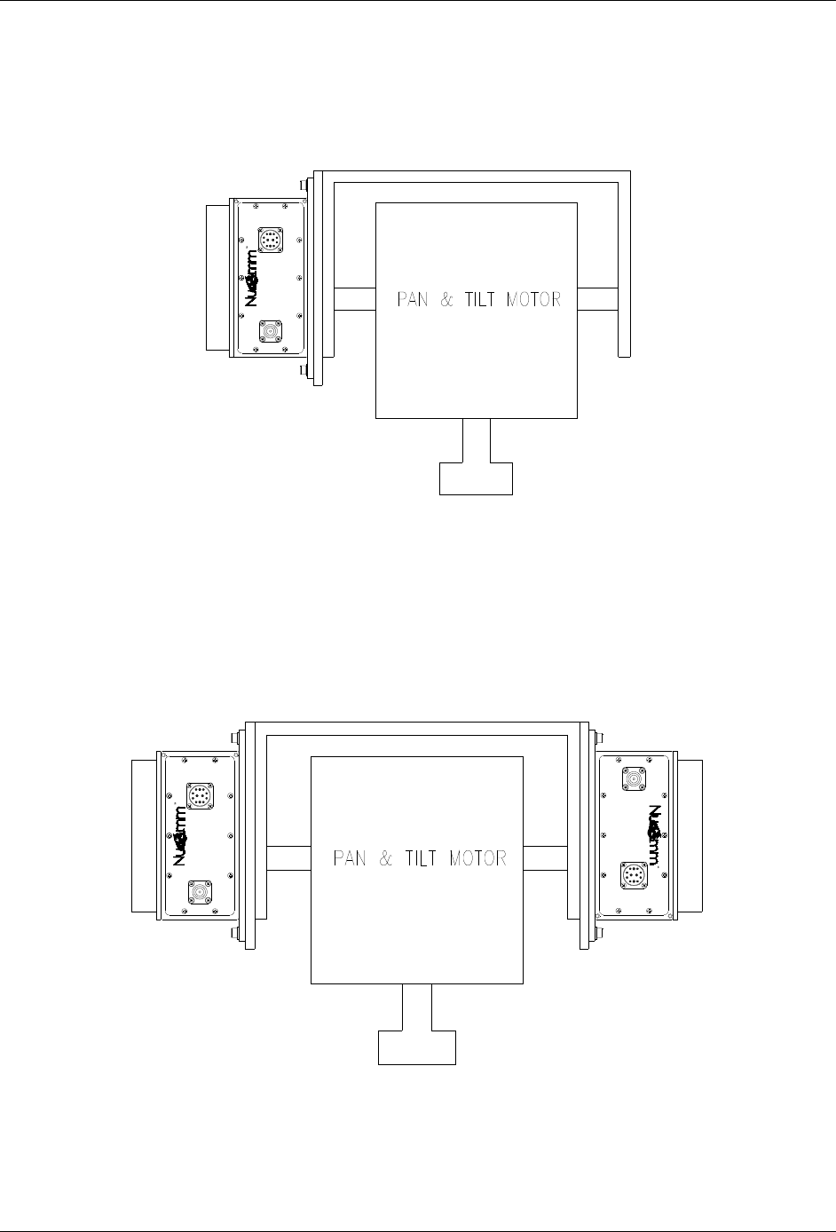
3.3. Mast Mounted HPA Mechanical Install
The Mast-Mounted HPAs are typically attached to the sides of the Pan & Tilt with Nucomm
mounting plates, as shown in Figures 3-9 & 3-10 (Single-Band and Dual-Band respectively).
Figure 3-9: HPA’s mounting on PAN & TILT (Single-band)
Figure 3-10: HPA’s mounting on PAN & TILT (Dual-band)
Revision 0.1
ChannelMaster Truck Package (PS18 & HPA/UHPA) 20
3.4. Mast Mounted HPA Electrical Install
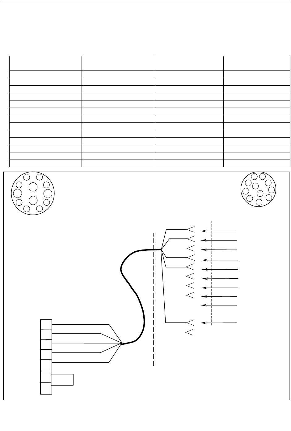
3.4.1 Prepare antenna control cable per Figure 3.11 (for NSI Antenna) & Figure 3.12 (for Radio Waves
Antenna).
NSI Quad Antenna Polarization Connector Pin Out
RF Head
Connector Pin
Function Recommended
Wire Size (AWG)
NSI Antenna
Connector Pin
N/C CW (Default) N/C N/C
E V #22 BROWN A
C H #22 RED B
D 2/7 GHz Band Select #22 GREEN L
F CCW #22 WHITE D
K Ground #22 BLACK E
J +24v #22 N/C
G Polarization Common #22 N/C
N/C N/C N/C F
N/C N/C N/C H
N/C N/C N/C J
N/C N/C N/C K
N/C N/C N/C M
Figure 3-11: NSI Quad Antenna Polarization Connector Pin Out
BROWN
RED
GREEN
WHITE
BLACK
NSI ANTENNA
POLARITY CONNECTOR
Nucomm P/N: 512-F3005-011
MS3106E-20-33S
(SOLDER SIDE)
A
B
C
D
E
F
H
J
K
L
M
V
H
CW (Default)
CCW
GND
2/7 BAND
V E
H C
2/7 GHz D
CCW F
GND K
+24V J
COMMON G
RF HEAD
BELDEN CABLE
#8445 (#22)
#9445 (#20)
P/N 821-05001-000
BRN
RED
WHT
BLK
GRN
A
D
C
B
E
K
F
H
M
L
NUCOMM RF HEAD
“ANT POL” CONNECTOR
Nucomm P/N: 512-F3001-120
MS3116F14-12S
(SOLDER SIDE)
A
C
G B
E
H
F
D
J
K
L
M
Revision 0.1
21 ChannelMaster Truck Package (PS18 & HPA/UHPA)
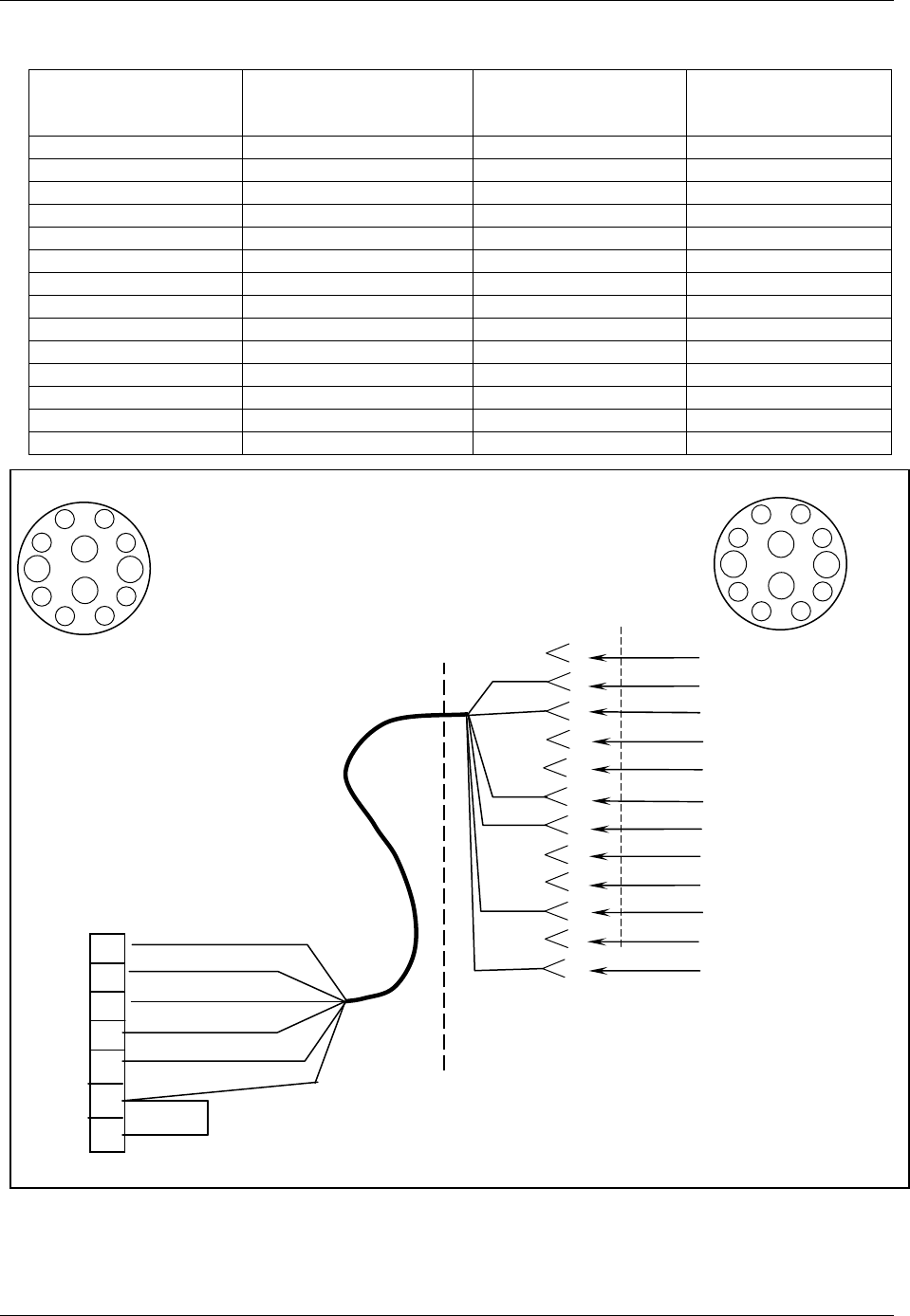
Radio Waves Quad Antenna Polarization Connector Pin Out
RF Head
Connector Pin
Function Recommended
Wire Size (AWG)
Radio Waves
Antenna
Connector Pin
N/C CW (Default) N/C N/C
E V #22 BROWN F
C H #22 RED B
D 2/7 GHz Band Select #22 GREEN G
F CCW #22 WHITE C
J +24V #22BLACK K
K GND #22 BLUE M
G Polarization Common #22 N/C
N/C Shield GND #22 L
N/C N/C N/C A
N/C N/C N/C D
N/C N/C N/C E
N/C N/C N/C H
N/C N/C N/C J
Figure 3-12: Radio Waves Quad Antenna Polarization Connector Pin Out
V E
H C
2/7 GHz D
CCW F
+24V J
GND K
Common G
NOTE: “CW” IS DEFAULT ON RADIO WAVES ANTENNAS
RADIO WAVES ANTENNA
POLARITY CONNECTOR
Nucomm P/N: 512-F3001-120
MS3116F14-12S
(SOLDER SIDE)
H
CCW
V
2/7 BAND SEL.
+24V
SHIELD GND
DC GND
A
B
C
D
E
F
G
H
J
K
L
M
BROWN
RED
GREEN
WHITE
BLACK
BLUE
BELDEN CABLE
#9430 (#22)
#9439 (#20)
P/N 821-05001-000
A
C
G B
E
H
F
D
J
K
L
M
RED
WHT
BRN
GRN
BLK
BLU
A
C
G B
E
H
F
D
J
K
L
M
NUCOMM RF HEAD
“ANT POL” CONNECTOR
Nucomm P/N: 512-F3001-120
MS3116F14-12S
(SOLDER SIDE)
Revision 0.1
ChannelMaster Truck Package (PS18 & HPA/UHPA) 22
RF OUTPUT
OMNI DIRECTIONAL
2GHz
IF INTERFACE POLARIZATION
ANTENNA
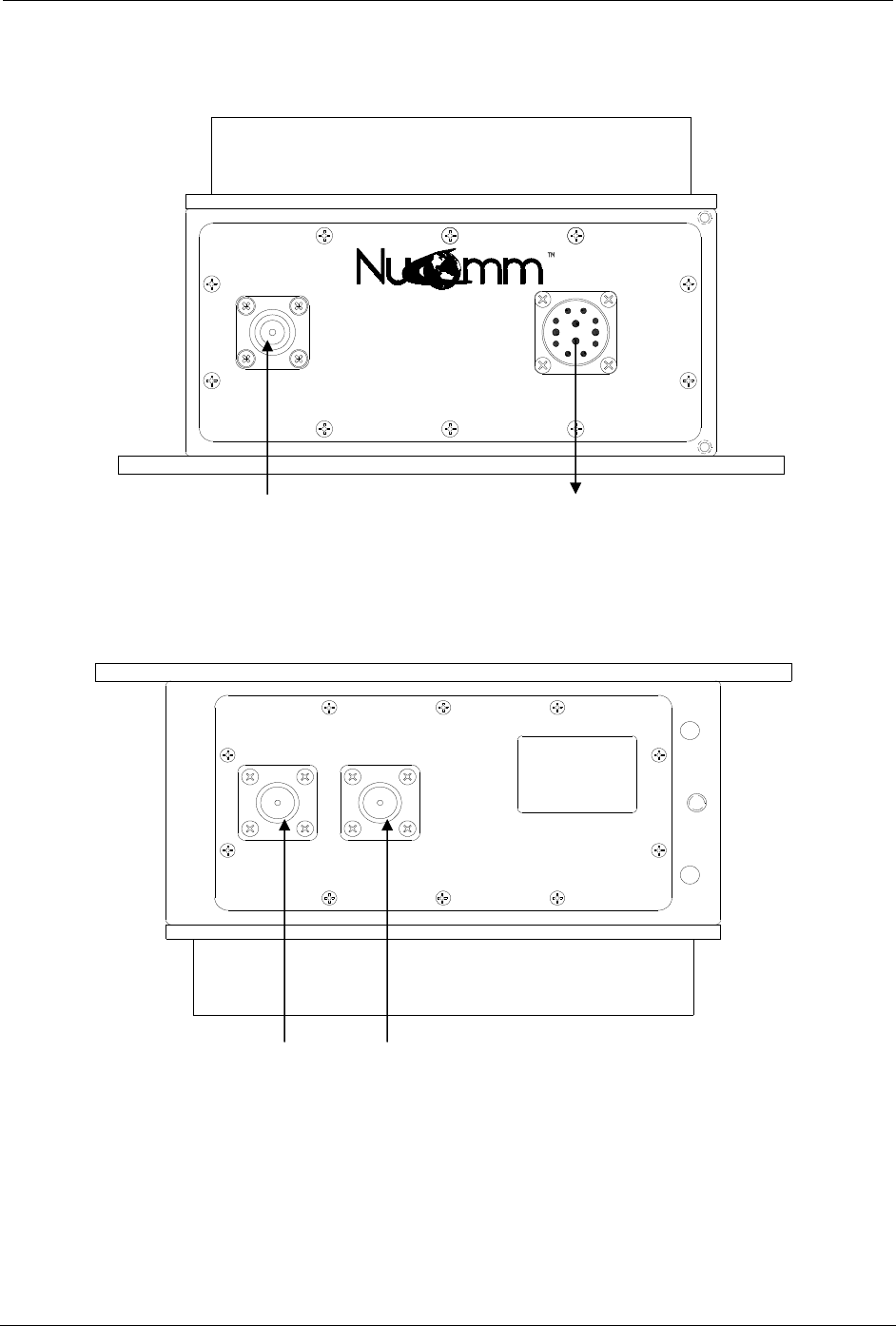
3.4.2 Make cable connections to RF Head and antenna(s). Refer to figures 3.11 & 3.12.
SF214 from Control Drawer
Antenna control to Antenna
Figure 3-11: RF Head Connections (IF& Antenna Polarization)
RF to Omni Antenna RF to Directional Antenna
Figure 3-12: RF Head Connections (RF to Antenna)
Revision 0.1
23 ChannelMaster Truck Package (PS18 & HPA/UHPA)
4.0 OPERATION
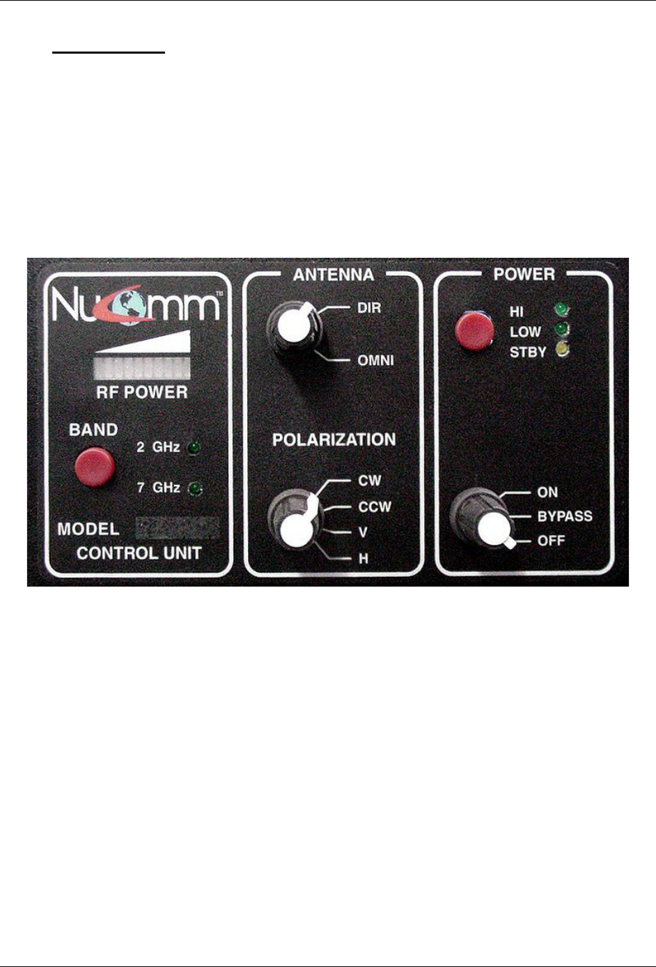
4.1. Control Drawer Front Panel
The Control Drawer Front Panel controls the selections related to the use of the 2GHz or 7GHz
High Power Amplifiers, as well as selecting various antenna parameters. (Refer to Figure 4-1.)
The controls are divided into three sections:
• Control Unit - for selecting the Power Amplifier band.
• Antenna - for selecting the type of antenna as well as directional antenna polarization.
• Power - for selecting the amplifier operation mode as well as overall unit mode.
Figure 4-1: Control Drawer Front Panel

Revision 0.1
ChannelMaster Truck Package (PS18 & HPA/UHPA) 24
4.2. Control Unit Section
The Control Unit section serves two purposes: the selection of which power amplifier is to be used,
and the monitoring of RF output power. The selection of amplifier is accomplished by pressing the
“Band” Button. The “Band” Button toggles the unit between enabling the 2GHz Amplifier and
the 7GHz Amplifier. This feature will still work even if the unit is placed into Bypass Mode.
For monitoring RF output power, a bar indicator is located just above the “Band” Button. As the
output power increases, so will the length of the bar indicator. However, there is no direct number
representation.
4.3. Antenna Section
The upper most rotary switch in the Antenna Section, allows the operator to choose the type of
antenna to be used. The operator can choose between either “Omni” or “Directional”. If
“Directional” is chosen, the operator then must set the lower most rotary switch for the type of
polarization to be used with the antenna.
There are four options:
• CW - Clockwise
• CCW - Counter-Clockwise
• V - Vertical
• H - Horizontal
4.4. Power Section
The Power Section allows the operator to select the unit’s mode of operation.
For choosing the unit’s mode of operation, the lower rotary switch can select one of three
conditions:
• OFF - The entire Control Unit is powered-off.
• BYPASS - The Mast Mounted Power Amplifier is powered down, while the RF signal
from the ChannelMaster is sent directly to the antenna via the Power Amp Bypass
Relays. Bypass Mode is used to further reduce the RF Power Level sent to the Antenna.
• ON - Allows the chosen power amplifier (refer to “Band” Button) to amplify the RF
output signal being applied to the Antenna.
If “ON” is chosen as the unit’s mode of operation, the amplifier mode of operation must then be
selected. This is accomplished by pressing the upper toggle button until the desired amplifier
mode is decided upon. There are three options:
• HI - places the Mast Mounted Power Amplifier in high power operation.
• LOW - places the Mast Mounted Power Amplifier in low power operation.
• STBY - places the Channel Transmitter in Standby Mode.

Revision 0.1
25 ChannelMaster Truck Package (PS18 & HPA/UHPA)

Revision 0.1
ChannelMaster Truck Package (PS18 & HPA/UHPA) 26
Nucomm Inc.
101 Bilby Road
Hackettstown, NJ 07840
Tel: 908-852-3700 Fax: 908-813-0399
www.Nucomm.com