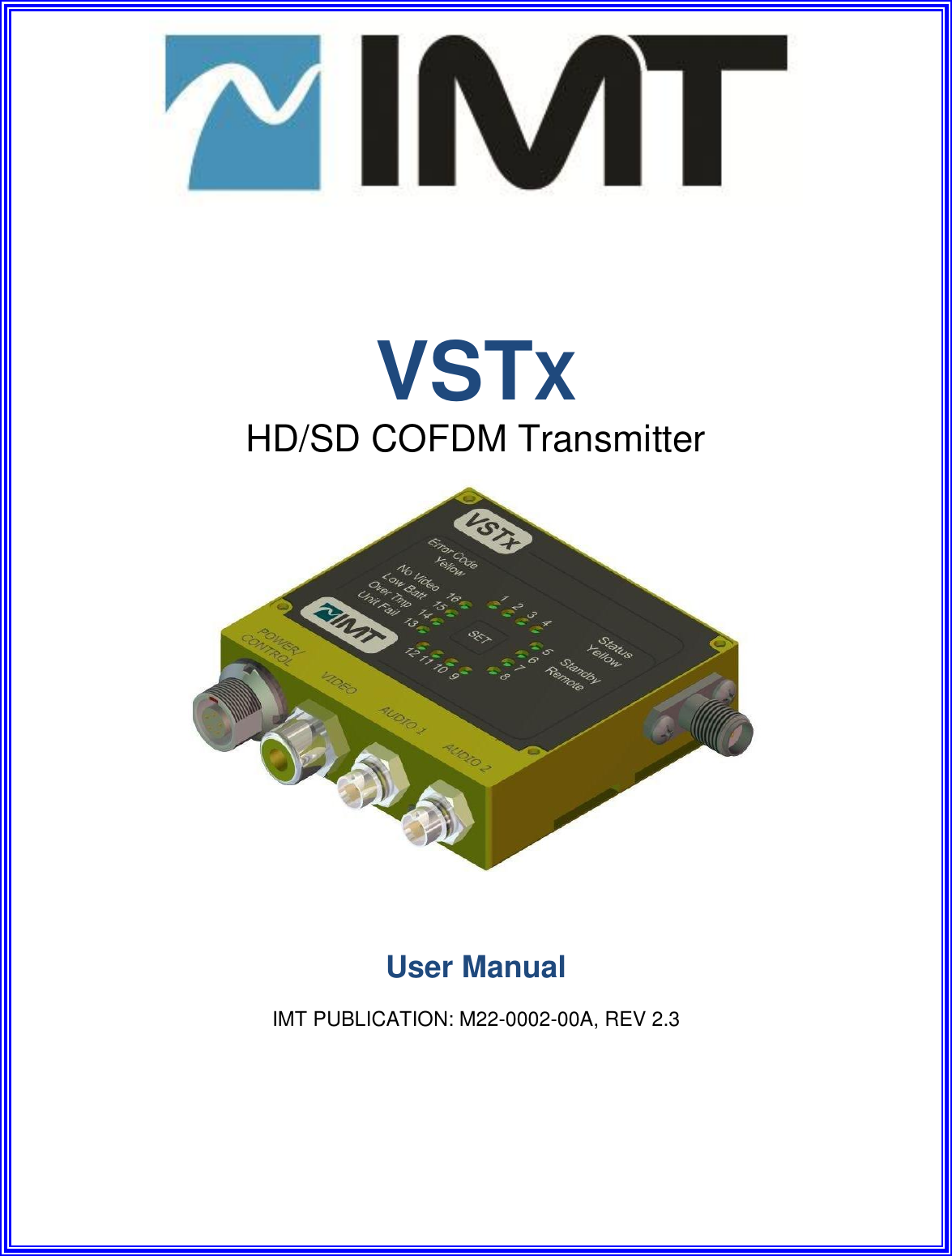
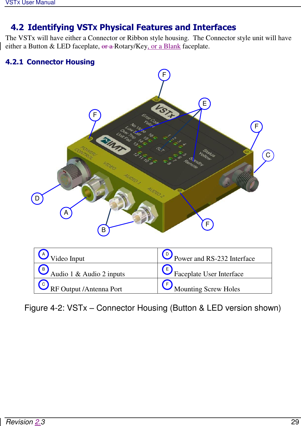
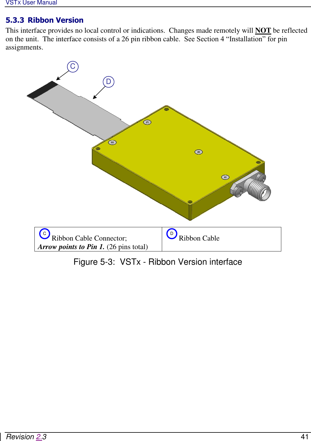
Integrated Microwave Technologies 25VST Ultra Compact SD COFDM Transmitter 25VST User Manual

Integrated Microwave Technologies, LLC. Ultra Compact SD COFDM Transmitter 25VST

User Manual

       VSTX HD/SD COFDM Transmitter       User Manual  IMT PUBLICATION: M22-0002-00A, REV 2.3
VSTX User Manual   Revision 2.3    2  Revision History  Date Revision Modified By Description October 1, 2009 1.0 JB Initial release October 12. 2011 1.1a Mike Hardy Major Update and cleanup.  Removed ASI/SDI. October 27. 2011 1.1b Mike Hardy Updated ribbon table November 28. 2011 2.0 Sean Van Update December 19. 2011 2.1 Alexander Minicozzi Jason provided FCC and IC Statements January 10. 2012 2.2 Jason Wang Added FCC & IC Label requirements January 25. 2012 2.3 Jason Wang Added RP-SMA Antenna Port for 25VST      IMT VSTX Users Manual IMT Publication: M22-0002-00A       IMT, LLC. 200 International Drive Mt. Olive, NJ, 07828, USA. T +1 908 852 3700   F +1 908 813 0399    www.imt-solutions.com         We make every effort to ensure our documentation is as accurate and as complete as possible.  In the event that you find any errors or omissions, please contact Customer Tech Support at (908) 852-3700, or via email a service@nucomm.com.  © Copyrighted 2011 - IMT, LLC - Mount Olive, New Jersey 07828
VSTX User Manual   Revision 2.3    3     This product has been approved by the following regulatory bodies at 2400 – 2483.5 MHz:  FCC (USA) IC (Canada)                   CAUTION!  RISK OF ELECTRICAL SHOCK.  DO NOT REMOVE COVERS.   Do not remove any covers Refer servicing to qualified technicians only Disconnect all power before servicing  Read and perform all instructions carefully Failure to follow suggested instructions and guidelines may void all warranties  PRUDENCE!  RISQUE DE CHOC ÉLECTRIQUE. NE SUPPRIMEZ PAS LES COUVERTURES.   Ne supprimez pas les couvertures Voir entretien à qualifiés Techniciens seulement. Déconnectez tous les pouvoir avant l'entretien. Lecture et effectuer toutes les instructions attentivement.  Échec de suivre les lignes directrices et les instructions proposées peut-être annuler toutes les garanties.
VSTX User Manual   Revision 2.3    4 FCC CAUTION/ PRUDENCE DE FAC  Any change or modification not approved by the party responsible for compliance could void the user’s authority to operate this device.  This device requires professional installation.   For operation within 2400 – 2483.5 MHz frequency range, the maximum EIRP must be less than 36 dBm. The qualified antenna types to be used with this device include: dipole antenna (3dBi or 5dBi)  This device complies with Part 15 of the FCC Rules. Operation is subject to the following two conditions: (1) This device may not cause harmful interference, and (2) this device must accept any interference received, including interference that may cause undesired operation.  In order to maintain compliance with the FCC RF exposure guidelines, this device should be installed and operated with a minimum distance of 20cm between the radiator, and the body of the operator and/or nearby persons.  Tout changement ou modification non approuvé par la partie responsable de la conformité pouvait annuler l'autorisation de l'utilisateur pour l'exploitation de ce dispositif.  Ce dispositif nécessite l'installation professionnelle.  Pour l'opération au sein de la gamme de fréquences de 2400 – 2483.5 MHz, la pire maximale doit être inférieure à 36 dBm. Les types d'antenne qualifiés pour être utilisé avec ce dispositif, citons :  Antenne dipôle faible Gain  (3dBi ou 5 dBi).  Cet appareil est conforme à la partie 15 des règles de la FCC. Opération est soumis à deux conditions suivantes: (1) ce dispositif ne peut pas causer de brouillage préjudiciable, et (2) ce dispositif doit accepter toute ingérence a reçu, y compris le brouillage qui peut provoquer l'opération non désirée.  Afin de maintenir la conformité avec les directives d'exposition RF FCC, ce dispositif doit être installé et exploité avec une distance minimale de 20 cm entre le radiateur et le corps de l'opérateur ou à proximité de personnes.       FCC STATEMENT This equipment (FCC ID: I4U-25VST) has been tested and found to comply with the limits for a Class B digital device, pursuant to part 15 of the FCC Rules.  DÉCLARATION DE FAC Cet équipement (FCC ID: I4U-25VST) a été testé et de respecter les limites pour une classe b dispositif numérique, conformément à la partie 15 des règles de la FCC.
VSTX User Manual   Revision 2.3    5 IC Notice/:IC Avis 1. Under Industry Canada regulations, this radio transmitter may only operate using an antenna of a type and maximum (or lesser) gain approved for the transmitter by Industry Canada. To reduce potential radio interference to other users, the antenna type and its gain should be so chosen that the equivalent isotropically radiated power (e.i.r.p.) is not more than that necessary for successful communication.  Conformément à la réglementation d'Industrie Canada, le présent émetteur radio peut fonctionner avec une antenne d'un type et d'un gain maximal (ou inférieur) approuvé pour   l'émetteur par Industrie Canada. Dans le but de réduire les risques de brouillage radioélectrique à l'intention des autres utilisateurs, il faut choisir le type d'antenne et son gain de sorte que la puissance isotrope rayonnée équivalente (p.i.r.e.) ne dépasse pas l'intensité nécessaire à l'établissement d'une communication satisfaisante.  2. This radio transmitter (IC: 9479A-25VST) has been approved by Industry Canada to operate with the antenna types listed below with the maximum permissible gain and required antenna impedance for each antenna type indicated. Antenna types not included in this list, having a gain greater than the maximum gain indicated for that type, are strictly prohibited for use with this device.  Le présent émetteur radio (identifier le dispositif par son numéro de certification ou son numéro de modèle s'il fait partie du matériel de catégorie I) a été approuvé par Industrie Canada pour fonctionner avec les types d'antenne énumérés ci-dessous et ayant un gain admissible maximal et l'impédance requise pour chaque type d'antenne. Les types d'antenne non inclus dans cette liste, ou dont le gain est supérieur au gain maximal indiqué, sont strictement interdits pour l'exploitation de l'émetteur.  Antenna Approved/Antenne approuvé Type/Type Max. Gain/Max. Gain Impedance/Impédance Dipole Antennas/ dipôle antennes 5 dBi 50 Ω  3. This device complies with Industry Canada licence-exempt RSS standard(s). Operation is subject to the following two conditions: (1) this device may not cause interference, and (2) this device must accept any interference, including interference that may cause undesired operation of the device.  Le présent appareil est conforme aux CNR d'Industrie Canada applicables aux appareils radio exempts de licence. L'exploitation est autorisée aux deux conditions suivantes : (1) l'appareil ne doit pas produire de brouillage, et (2) l'utilisateur de l'appareil doit accepter tout brouillage radioélectrique subi, même si le brouillage est susceptible d'en compromettre le fonctionnement.  4. In order to maintain compliance with the IC RF exposure guidelines, this device should be installed and operated with a minimum distance of 20 cm between the radiator, and the body of the operator and/or nearby persons.
VSTX User Manual   Revision 2.3    6 Afin de maintenir la conformité avec les directives d'exposition RF IC, ce dispositif doit être installé et exploité avec une distance minimale de 20 cm entre le radiateur et le corps de l'opérateur ou à proximité de personnes.      FCC / IC Label Requirement   If the FCC /IC ID is not visible when the I4U-25VST / 9479A-25VST module is installed inside another OEM device, then the outside of the OEM device into which the module is installed must also display a label referring to the enclosed module.  This exterior label can use wording such as the following: “Contains Transmitter Module FCC ID: I4U-25VST”/ IC: 9479A-25VST” or “Contains FCC ID: I4U-25VST. / IC: 9479A-25VST” Any similar wording that expresses the same meaning may be used.    FAC / IC Label exigence SI LE FCC /IC ID N'EST PAS VISIBLE LORSQUE LA I4U-25VST / 9479A-25VST MODULE EST INSTALLÉ À L'INTÉRIEUR D'UN AUTRE PÉRIPHÉRIQUE OEM, ALORS QUE L'EXTÉRIEUR DE L'APPAREIL OEM DANS LEQUEL EST INSTALLÉ LE MODULE DOIT ÉGALEMENT AFFICHER UNE ÉTIQUETTE SE RÉFÉRANT AU MODULE CI-JOINT.  CETTE ÉTIQUETTE EXTÉRIEURE PEUT UTILISER LIBELLÉ COMME SUIT: "CONTAINS ÉMETTEUR MODULE ID FCC: I4U-25VST" / IC: 9479A-25VST "OU" CONTAINS FCC ID: I4U-25VST. / IC: 9479A-25VST "TOUTE FORMULATION SEMBLABLE QUI EXPRIME LE MÊME SENS PEUT-ÊTRE ÊTRE UTILISÉE.
VSTX User Manual   Revision 2.3    7 Contents 1 Introduction ............................................................................................................................... 14 1.1 Manual Overview ........................................................................................................................... 14 2 VSTX Description ...................................................................................................................... 16 2.1 VSTX Features and Benefits ....................................................................................................... 16 2.1.1 VSTX Application Diagram ........................................................................................................................... 17 2.1 VSTX Theory of Operation .......................................................................................................... 18 2.1.1 VSTX Block Diagram ..................................................................................................................................... 18 2.1.2 Power and Control Interface Connector ................................................................................................... 20 2.1.3 Audio and Video Input Connectors ............................................................................................................ 20 2.1.4 User Data Input ............................................................................................................................................ 20 2.1.5 MPEG4 Encoder ............................................................................................................................................ 20 2.1.6 Encryption ..................................................................................................................................................... 20 2.1.7 COFDM Modulator ........................................................................................................................................ 20 2.1.8 L, S,  and C Band Transmitter .................................................................................................................... 21 2.1.9 Ultra Compact Case ..................................................................................................................................... 21 2.1 Remote Control and Firmware ................................................................................................. 21 2.1.1 Remote Control via Serial Interface .......................................................................................................... 21 2.1.2 Firmware updates ........................................................................................................................................ 21 3 Specifications ............................................................................................................................ 24 3.1 Frequency Bands ........................................................................................................................... 24 3.2 Modulation Modes ......................................................................................................................... 24 3.3 MPEG Encoder ................................................................................................................................ 25 3.4 System ............................................................................................................................................... 25 3.5 Power Requirements ................................................................................................................... 25 3.6 Environmental ................................................................................................................................ 26 3.7 Physical Specifications ................................................................................................................ 26 4 Installation ................................................................................................................................. 28 4.1 Overview .......................................................................................................................................... 28 4.2 Identifying VSTX Physical Features and Interfaces ......................................................... 29 4.2.1 Connector Housing ....................................................................................................................................... 29 4.2.2 Ribbon Housing ............................................................................................................................................ 31 4.3 Physical Installation .................................................................................................................... 32 4.4 Connect External Signals (Connector Housing) ................................................................. 33 4.4.1 Power and Control (Connector Housing) .................................................................................................. 33 IMT part # ..................................................................................................................................................................... 33 Cable Description .......................................................................................................................................................... 33 CableType ..................................................................................................................................................................... 33 7pin LEMO to bare tin strip leads ................................................................................................................................. 33 Power Input cable ......................................................................................................................................................... 33 7pin LEMO to bare tin strip leads, w/DB9 .................................................................................................................... 33
VSTX User Manual   Revision 2.3    8 Power Input cable (w/Control) ..................................................................................................................................... 33 4.4.2 Video Input (Connector Housing) .............................................................................................................. 35 4.4.3 Audio Input (Connector Housing) .............................................................................................................. 35 4.5 Connect External Signals (Ribbon Housing) ....................................................................... 35 4.6 Antenna Installation .................................................................................................................... 36 5 Operation ........................................................................................................................................ 38 5.1 Power Up the VSTX ....................................................................................................................... 38 5.2 Pre-Configure the VSTX user options .................................................................................... 38 5.3 User Interfaces .............................................................................................................................. 39 5.3.1 Button & LED Interface ............................................................................................................................... 39 5.3.2 Rotary/Key Interface ................................................................................................................................... 40 5.3.3 Ribbon Version .............................................................................................................................................. 41 5.3.3.1 PA AGC Signal ..................................................................................................................................... 42 5.3.3.2 RS232 RX UD ....................................................................................................................................... 42 5.3.3.3 RS232 Remote Control RS-232 Tx / Rx ........................................................................................... 42 5.3.3.4 USB_PWR ............................................................................................................................................. 42 5.3.3.5 USB_DP/USB_DM ................................................................................................................................ 42 5.3.3.6 Composite Video ................................................................................................................................. 42 5.3.3.7 +12VDC ................................................................................................................................................ 42 5.3.3.8 Audio 1, Audio 2 Inputs ..................................................................................................................... 42 5.4 Using the VSTX to Transmit Audio and Video Signals ...................................................... 43 5.4.1 Select User Level Settings ........................................................................................................................... 43 5.4.2 Put the unit in Transmit Mode .................................................................................................................... 43 5.4.3 Select Power Level ....................................................................................................................................... 43 5.4.4 Verify Operation ........................................................................................................................................... 43 5.5 Using the VSTX To Transmit User Data (Ribbon version only) ..................................... 43 5.6 Using alternate/custom controllers ....................................................................................... 44 5.6.1 Serial Interface Rate, Parity, and Stop Bit Specifications ....................................................................... 44 5.6.2 Command and Response Packet Formats ................................................................................................ 44 5.7 Troubleshooting ............................................................................................................................. 45 5.8 Maintenance Information .......................................................................................................... 45 1 Introduction ..................................................................................................................................... 8 1.1 Manual Overview ................................................................................................................................. 8 2 VSTx Description ........................................................................................................................... 10 2.1 VSTx Features and Benefits.............................................................................................................. 10 2.1.1 VSTx Application Diagram ............................................................................................................................ 11 2.1 VSTx Theory of Operation ............................................................................................................... 12 2.1.1 VSTx Block Diagram ..................................................................................................................................... 12 2.1.2 Power and Control Interface Connector ......................................................................................................... 14 2.1.3 Audio and Video Input Connectors ................................................................................................................ 14 2.1.4 User Data Input............................................................................................................................................... 14 2.1.5 MPEG4 Encoder ............................................................................................................................................. 14 2.1.6 Encryption ...................................................................................................................................................... 14 2.1.7 COFDM Modulator ........................................................................................................................................ 14 2.1.8 L, S, C, and X Band Transmitter .................................................................................................................... 15
VSTX User Manual   Revision 2.3    9 2.1.9 Ultra Compact Case ........................................................................................................................................ 15 2.1 Remote Control and Firmware ........................................................................................................ 15 2.1.1 Remote Control via Serial Interface ............................................................................................................... 15 2.1.2 Firmware updates ........................................................................................................................................... 15 3 Specifications ................................................................................................................................. 18 3.1 Frequency Bands ............................................................................................................................... 18 3.2 Modulation Modes ............................................................................................................................. 18 3.3 MPEG Encoder .................................................................................................................................. 19 3.4 System ................................................................................................................................................. 19 3.5 Power Requirements.......................................................................................................................... 19 3.6 Environmental .................................................................................................................................... 20 3.7 Physical Specifications ....................................................................................................................... 20 4 Installation ..................................................................................................................................... 22 4.1 Overview ............................................................................................................................................. 22 4.2 Identifying VSTx Physical Features and Interfaces ....................................................................... 23 4.2.1 Connector Housing ......................................................................................................................................... 23 4.2.2 Ribbon Housing .............................................................................................................................................. 25 4.3 Physical Installation ........................................................................................................................... 26 4.4 Connect External Signals (Connector Housing) ............................................................................. 27 4.4.1 Power and Control (Connector Housing) ....................................................................................................... 27 4.4.2 Video Input (Connector Housing) .................................................................................................................. 29 4.4.3 Audio Input (Connector Housing) .................................................................................................................. 29 4.5 Connect External Signals (Ribbon Housing) ................................................................................... 29 4.6 Antenna Installation .......................................................................................................................... 30 5 Operation ........................................................................................................................................ 32 5.1 Power Up the VSTx ........................................................................................................................... 32 5.2 Pre-Configure the VSTX user options ............................................................................................. 32 5.3 User Interfaces ................................................................................................................................... 33 5.3.1 Button & LED Interface ................................................................................................................................. 33 5.3.2 Rotary/Key Interface ...................................................................................................................................... 34 5.3.3 Ribbon Version ............................................................................................................................................... 35 5.3.3.1 PA AGC Signal ..................................................................................................................................... 36 5.3.3.2 RS232 RX UD ...................................................................................................................................... 36 5.3.3.3 RS232 Remote Control RS-232 Tx / Rx ............................................................................................... 36 5.3.3.4 USB_PWR ............................................................................................................................................ 36 5.3.3.5 USB_DP/USB_DM .............................................................................................................................. 36 5.3.3.6 Composite/S-Video ............................................................................................................................... 36 5.3.3.7 +12VDC ................................................................................................................................................ 36 5.3.3.8 Audio 1 With Bias ................................................................................................................................ 36 5.3.3.9 Audio 2 With Bias ................................................................................................................................ 36 5.3.3.10 Audio 1, Audio 2 Inputs ........................................................................................................................ 36 5.4 Using the VSTx to Transmit Audio and Video Signals .................................................................. 37 5.4.1 Select User Level Settings .............................................................................................................................. 37
VSTX User Manual   Revision 2.3    10 5.4.2 Put the unit in Transmit Mode ........................................................................................................................ 37 5.4.3 Select Power Level ......................................................................................................................................... 37 5.4.4 Verify Operation ............................................................................................................................................. 37 5.5 Using the STx To Transmit User Data ............................................................................................. 37 5.6 Using alternate/custom controllers ................................................................................................... 38 5.6.1 Serial Interface Rate, Parity, and Stop Bit Specifications .............................................................................. 38 5.6.2 Command and Response Packet Formats ....................................................................................................... 38 5.7 Troubleshooting ................................................................................................................................. 39 5.8 Maintenance Information ................................................................................................................. 39
VSTX User Manual   Revision 2.3    11 Figures  Figure 2-1: VSTX Application ______________________________________________________________________ 18 Figure 2-2: Nucomm VSTX Internal Block Diagram ___________________________________________________ 19 Figure 2-3 - Encryption Circuit _____________________________________________________________________ 20 Figure 4-1:  VSTX Application With Optional Host Processor ___________________________________________ 28 Figure 4-2: VSTx – Connector Housing (Button & LED version shown) __________________________________ 29 Figure 4-3: VSTX – Button & LED faceplate _________________________________________________________ 30 Figure 4-4: VSTX – Rotary/Key faceplate ____________________________________________________________ 30 Figure 4-5:  VSTx - Ribbon Housing ________________________________________________________________ 31 Figure 4-6: VSTX Outline Drawing, Connector Housing (Dimensions in Inches) ___________________________ 32 Figure 4-7: VSTx (Connector Housing) Power/Control Detail __________________________________________ 34 Figure 4-8: VSTx (Connector Housing) Audio Detail __________________________________________________ 35 Figure 5-1: VSTx – Button & LED interface __________________________________________________________ 39 Figure 5-2: VSTX – Rotary/Key interface ____________________________________________________________ 40 Figure 5-3:  VSTx - Ribbon Version interface ________________________________________________________ 41  Tables  Table 2-1: VSTX - Summary of High Level Features and Benefits ______________________________________ 16 Table 4-1: VSTx (Connector Housing) Power/Control Cables __________________________________________ 33 Table 4-2: VSTx (Connector Housing) Power/Control Pinout ___________________________________________ 34 Table 4-3: VSTx (Connector Housing) Audio Pinout __________________________________________________ 35 Table 4-4: Ribbon Cable Connector Cable Pin Assignments ___________________________________________ 36 Table 5-1: Table of Troubleshooting Tips ___________________________________________________________ 45
VSTX User Manual   Revision 2.3    12
VSTX User Manual   Revision 2.3    13           Chapter One1Introduction
VSTX User Manual   Revision 2.3    14 1 Introduction  This document is a user manual for IMT’s VSTX microwave video transmitter. The VSTX is a compact transmitter that digitally encodes video signals and transmits them using COFDM modulation over microwave frequencies using secure methods. The unit accepts Composite video inputs in NTSC or PAL format. It has a built in MPEG4 (H.264) encoder and COFDM modulator. The VSTX is housed in an ultra compact, lightweight enclosure that can be used in harsh environments.  The VSTx comes in two versions, a “connectorized” version which has connectors for typical user inputs and outputs and a user interface panel, and a “ribbon cable” version which has no external connectors or controls.    Throughout this manual, the product is referred to as the “VSTX,” the “VSTX transmitter”, or simply the “transmitter.”  1.1 Manual Overview  The contents of this manual are as follows:  Chapter 2 – Describes the theory of operation and the features of the VSTX.  Chapter 3 – Contains a list of the VSTX specifications. The specifications include transmitter feature specifications, power requirements, environmental specifications, and I/O specifications.   Chapter 4 – Explains how to install the VSTX.   Chapter 5 – Describes operating procedures for the VSTX. It also contains an overview of the VSTX programmable serial interface.  A preface at the front of this manual contains Warranty and Repair information.   The rear of this manual contains warranty and repair information.
VSTX User Manual   Revision 2.3    15             Chapter Two2Description
VSTX User Manual   Revision 2.3    16 2 VSTX Description  This chapter describes the VSTX transmitter theory of operation, features, and benefits. It also contains a block diagram of the VSTX transmitter circuitry and a typical application example.   The VSTx is available in two basic versions:   VSTx with external input connectors  VSTx with ribbon cable interface   The VSTx with external connectors features direct plug-in compatibility with off the shelf equipment using industry standard interfaces.  The VSTx using a ribbon cable interface is slightly smaller and is useful for space optimized solutions. Audio and Video are input to the VSTX through the ribbon cable. A programmable user interface is also accessed via a serial port in the ribbon cable. This can be used to pre-configure the VSTX settings and to check the status of the VSTX settings. Power is also supplied to the VSTX through the ribbon cable.   The VSTX internal circuitry compresses the audio and video signals, organizes the compressed data into ISO digital video transport streams, and optionally encrypts the data. The transmitter uses COFDM modulation and transmits at microwave frequencies in the bands supported by the unit.  Though the unit ships pre-configured, a graphical user interface that runs on a PC is available to modify the operating parameters. Optionally, custom software written to implement the RS232 command set may be used. Refer to Chapter 5, “Operation” for more information.  IMT has the ability, should the need ever arise, to provide the user with firmware files and instructions for local firmware installation, such as for feature upgrades, etc. 2.1 VSTX Features and Benefits  Table 2-1: VSTX - Summary of High Level Features and Benefits  Feature Benefit COFDM Microwave Digital Video Transmitter Microwave output frequencies in the L, S, C, and C bands.  X bands.    L, S, C, and  X C Band Transmitter Output Frequencies User orderable frequency band options.  User programmable channels and offsets within frequency ranges.  Accepts NTSC or PAL Composite Video Inputs Compatible with industry standard video camera outputs.  Optional Stereo Analog Audio Inputs Direct audio input option for use with video signals that do not contain audio.
VSTX User Manual   Revision 2.3    17 MPEG4 (H.264) Encoder Industry standard video compression.  Implements latest algorithms including B frames.  User Data Channel Data can be transmitted along with audio and video to the receiver on the ribbon version only.  Remote Control GUI for Programming the VSTx Convenient menu and button based graphical user interface for Windows PC’s.  Can be used to program the preset settings on the top panel. GUI uses VSTx RS-232 remote control serial port. Ultra Compact Housing Fits in small form factor products.  Optional Ribbon I/O Cable The VSTX uses a compact, flexible ribbon cable to connect to other equipment.    2.1.1 VSTX Application Diagram  Figure 2-1 shows a typical VSTX transmitter application. The External Equipment Interface connects to other circuits using a ribbon cable. An antenna is connected to the SMA (or RP-SMA for 25VST ) antenna output port.   The VSTX may be programmed by a host processor in the application, or it may be pre-configured and installed in the application without programming during operation. The latter approach can save expense in cost sensitive applications.   Commonly used configurations can be setup and stored in the VSTX memory as “preset” configurations. Up to 16 presets can be stored. Once presets have been stored, fewer commands are required to change between configurations.
VSTX User Manual   Revision 2.3    18     VSTxCamera CircuitPower SourceHost Processor(For VSTx Configuration) Antenna  Figure 2-1: VSTX Application   2.1 VSTX Theory of Operation 2.1.1 VSTX Block Diagram  Figure 2-2 is a block diagram of the VSTX internal circuitry.  Major blocks in the VSTX include:   NTSC Composite Video Input Interface  Stereo Audio Input Interface  MPEG4 Video Compression Circuit  Data Encryption Circuit  COFDM Modulator  Microwave Transmitter and Antenna Connector  Programmers Serial Interface for Remote Control Purposes  Internal Microprocessor and Memory  USB Interface for Firmware Updates  Power Circuitry
VSTX User Manual   Revision 2.3    19           MPEG4EncoderCOFDM ModulatorAES Data EncryptionMicrowave TransmitterMicroprocessor and Flash MemoryPowerAudio Input CircuitVideo Input CircuitUser Data Serial PortProgrammable Serial PortUSB Interface Circuit (Ribbon only)UI Buttons and LED’s  Figure 2-2: IMTNucomm VSTX Internal Block Diagram
VSTX User Manual   Revision 2.3    20 2.1.2 Power and Control Interface Connector The VSTx Power and Control Interface includes power and ground connections plus two RS-232 serial port interfaces. One of the RS-232 interfaces can be connected to a laptop or other PC to program the transmitter configuration. The second RS-232 interface can be used to transmit user data through the transmitter along with the audio and video streams.  2.1.3 Audio and Video Input Connectors This VSTX model has two analog audio inputs that can be used for stereo audio and one NTSC or PAL composite video input. Refer to Chapter 3 for specifications of these signals.  2.1.4 User Data Input User Data is available on the ribbon version only.   In the “ribbon” version aA data channel may be transmitted along with the audio and video information. The data channel is accessed through a separate RS-232 serial interface on the ribbon connectorin the Power/Control connector.  2.1.5 MPEG4 Encoder The VSTX compresses the input video signal before modulation and transmission to reduce bandwidth. The VSTX contains a built-in MPEG4 (H.264) compliant encoder for this purpose. The VSTx features the latest compression methods utilizing B frames for more accurate encoding of compressed video signals.   2.1.6 Encryption The transmitter supports BCRYPT1 and BCRYPT2. BCRYPT2 is very similar to BCRYPT1 with improvements made to support re-multiplexing. Both encryption modes support AES 128 and AES256 key lengths.    MPEG4 EncoderCOFDMModulatorAES Encryption RF Output  Figure 2-3 - Encryption Circuit  2.1.7 COFDM Modulator  The COFDM modulator receives data from the output of the MPEG4 encoder through a circuit that enhances the security of transmissions.  The VSTX is able to transmit data at high data rates and with low error rates using COFDM modulation techniques. The data rate used by the transmitter depends upon the CODFM modulator settings used.  Refer to Chapter 5, “Operation” for more information.
VSTX User Manual   Revision 2.3    21 2.1.8 L, S,  and C Band, and X Band Transmitter The VSTX microwave transmitter circuits mix the signal to the desired microwave frequency. The signal is filtered and boosted through a low noise output amplifier.   The VSTX has a single SMA (or RP-SMA for 25VST ) style antenna connector. The output impedance of the antenna connector is 50 ohms.   Refer to Chapter 3, “Specifications” for frequency band and channel tuning specifications. 2.1.9 Ultra Compact Case The VSTX case is compact and can be screw mounted to other surfaces.   The VSTx contains a PCB near the lower surface of the unit. The bottom of the VSTx dissipates most of the VSTx heat. Thus it is important to mount the VSTx in a manner which keeps the bottom surface of the VSTx within the transmitter’s operating temperature range.    Refer to Chapter 4, “Installation,” for more information about the VSTX housing, connector pin  assignments, and antenna port. 2.1 Remote Control and Firmware 2.1.1 Remote Control via Serial Interface An RS-232 command set is implemented to allow remote control of all configuration options, as well as monitoring of internal status and settings.  Commands and responses are sent via the RS-232 serial interface located on the Power/Control connector.    The IMTOur “Nano Controller” GUI is available for controlling the unit via the RS-232 serial interface. Any Windows compatible computer running Windows XP or Vista with 500 MB of memory and 1 GHz Pentium or above can be used.  Refer to Chapter 5, “Operation” for more information.    Optionally, users can create custom control interfaces as required to suit their applications. The RS-232 command set, or “remote protocol”, is available upon request for this purpose. 2.1.2 Firmware updates  The unit firmware may be updated via the USB interface on the Power/Control connector, using the Nucommour NanoTx Programmer software.  A programming cable (IMT part number 922-B963-01A-R, or equivalent) is required. Contact IMT Tech Support for additional details.
VSTX User Manual   Revision 2.3    22
VSTX User Manual   Revision 2.3    23            Chapter Three3Specifications
VSTX User Manual   Revision 2.3    24 3 Specifications  3.1 Frequency Bands   Base Part Number Frequency (GHz) RF Power (dBm) DC Power (W) 13VST-13 1.200-1.400 13 4 13VST-20 1.200-1.400 20 6 23VST-13 2.200-2.400 13 64 23VST-20 2.200-2.400 20 6 25VST-13 2.400-2.500 20 4 47VST-13 4.400-5.000 13 65 47VST-20 4.400-5.000 20 6 47VST-23 4.400-5.000 23 8 (Other bands may be available.  Contact IMT)   Tuning step size:  ........................................... 1MHz step size Frequency stability:  ...................................... ± 10ppm  Transmit Modes: Standby:  ........................................................ No RF output Normal:  ......................................................... Instantly on frequency transmission  3.2 Modulation Modes Modulation 1 Modulation Formats:  .......................................... COFDM (DVB-T) Carriers:  .............................................................. 2K Constellation:  ...................................................... QPSK, 16QAM Code Rate:  .......................................................... 1/2, 2/3, 3/4, 5/6, 7/8 Guard Interval:  .................................................... 1/32, 1/16, 1/8, 1/4  Bandwidth:  .......................................................... 6 MHz, 7 MHz, and 8 MHz  Modulation 2 (Optional) Modulation Formats:  .......................................... COFDM (Proprietary) Carriers:  .............................................................. 2K Constellation: ....................................................... QPSK  Code Rate:  .......................................................... 1/2, 3/4 Guard Interval:  .................................................... 1/32  Bandwidth:  .......................................................... 1.25MHz, 2.5MHz
VSTX User Manual   Revision 2.3    25  (Other modulations available per user requirements) 3.3 MPEG Encoder  Method:  ..................................................................... MPEG-4 Part 10/H.264  Video Video Coding: ...................................................... AVC Video Input: ......................................................... Composite NTSC:  ......................................... 720 x 480(4:2:0) PAL:  ............................................ 720 x 576(4:2:0)  Audio Audio Coding:   ................................................... ISO/IEC 11172-3(Layer II) Audio Sample Rate: .............................................  48Khz Audio Channels:  ................................................. 1 Stereo, 2Mono Standard,  Audio Input:  ........................................................ Line, Gain selectable    ............................................................................. Mic, Gain selectable   ............................................................................. Phantom  power or external bias. Tone: .................................................................... -10dBfs/8dBm  ............................................................................. Level Adjustable -10 to-26dBfs  3.4 System Video Present: .........................................................  Remote Standby or Test Generator Test Generator (Dynamic):  .................................... SMPTE CB(NTSC)/100%  ................................................................................ CB(PAL)  .................................................................... 16 Character ID (Matches SDT Service name).  .................................................................... 1KHz Tone/Pulse   Encryption (optional): .............................................  AES Block Cypher, supporting key size of 128 and 256bit (FIPS PUB 197) User Data (:  Ribbon Version only): .......................  RS232 Side channel, 300-115K Baud Remote Control:  ..................................................... Remote RS232 Local Control:   ....................................................... See Figure 1: Local Control Panels Presets:    ........................................................... 16 user configurable presets withthrough windows GUI. 3.5 Power Requirements Input range:  ............................................................ DC: +9 to +18 Power consumption:  .............................................. See table above
VSTX User Manual   Revision 2.3    26 3.6 Environmental  Item Specification Temperature Range, Operational, Bottom Surface –10° to +65°C (Base plate temperature. The bottom surface of the VSTX must be maintained within the temperature range listed here.) Temperature Range, Storage –40° to +80°C Humidity 0% to 95% RH, non-condensing Altitude, Operating 0 to 20,000ft (6,000 m) Maximum Altitude, Storage 0 to 50,000ft (15,000 m) Maximum  3.7 Physical Specifications  Size (Flex version):  ................................................... 2.1"  x 0.3” x 1.6” Weight:  ..................................................................... 26.3g Size (Connector version):  ......................................... 2.1"  x 0.48” x 1.95” Weight: ......................................................................  45.4g (Sizes do not include connectors)  Connector Part Numbers: 7 pin Lemo (on TX) ................................................... ECG.0B.307.CLN IMT PN .......................................................... 512-F3022-007-R 7 pin Lemo (mating) .................................................. FGG.0B.307.CLAD52 IMT PN .......................................................... 512-F3022-007-R
VSTX User Manual   Revision 2.3    27            Chapter Four4Installation
VSTX User Manual   Revision 2.3    28 4 Installation  This chapter contains steps for installing the VSTx transmitter in typical environments where it may be used.  ______________________________________________________________  ! WARNING – DO NOT OPEN THE VSTX   The VSTX contains no user serviceable parts. Do not open the VSTX housing. Failure to comply will result in voiding of the VSTX warranty.  ______________________________________________________________   4.1 Overview  The VSTX is used in compact systems that typically contain a camera and power supply. VSTX applications may also contain a host processor that is used in the field to re-configure settings in the VSTX.    VSTxCamera CircuitPower SourceHost Processor(For Nano Tx Configuration) Antenna  Figure 4-1:  VSTX Application With Optional Host Processor
VSTX User Manual   Revision 2.3    29 4.2 Identifying VSTX Physical Features and Interfaces The VSTx will have either a Connector or Ribbon style housing.  The Connector style unit will have either a Button & LED faceplate, or a Rotary/Key, or a Blank faceplate.  4.2.1 Connector Housing CEFFFFDAB  AVideo Input DPower and RS-232 Interface BAudio 1 & Audio 2 inputs EFaceplate User Interface CRF Output /Antenna Port FMounting Screw Holes  Figure 4-2: VSTx – Connector Housing (Button & LED version shown)
VSTX User Manual   Revision 2.3    30      Figure 4-3: VSTX – Button & LED faceplate      Figure 4-4: VSTX – Rotary/Key faceplate
VSTX User Manual   Revision 2.3    31 4.2.2 Ribbon Housing  CDAAAABE AScrew Holes for Mounting DRibbon Cable BVSTX Top Surface EAntenna Port CRibbon Cable Connector;  Arrow points to Pin 1. (26 pins total)   Figure 4-5:  VSTx - Ribbon Housing
VSTX User Manual   Revision 2.3    32 4.3 Physical Installation  Note: The VSTX is configured via the programmable serial interface. Should you desire to program the unit while in your application, then you r application design must provide a means to connect to the serial interface.   If your application cannot support a means to connect to the serial interface, then you must pre-configure the unit prior to installation.  Refer to Section 5.  The VSTX can be mounted using the four screw holes located on the corners of the housing, using four #2-56 screws. Tighten the four screws gradually in rotation, without applying excess force on one before starting the others.   The STx requires installation using proper thermal dissipation methods. During operation, energy is dissipated to the outside environment, especially on the lower surface of the unit.  The bottom surface of the VSTx must be kept at a temperature within the operating temperature range specified in Chapter 3.   The unit has an internal fan and the fan openings must not be blocked.     The unit should not be operated inside another enclosure unless sufficient cooling is provided that the case temperature is within the range specified in Chapter 3.    Figure 4-6: VSTX Outline Drawing, Connector Housing (Dimensions in Inches)
VSTX User Manual   Revision 2.3    33 4.4 Connect External Signals (Connector Housing)  The VSTX connectors include the following major interfaces:  Power and Ground Plus RS-232 programming interface  Video Input Connector  Accepts Composite Video  Analog Audio 1 and 2 Line Inputs 4.4.1 Power and Control (Connector Housing)  IMT has pre-made cables available that support Power and/or RS232 Control.  The power portion of the IMT cable has two bare tin leads for connection  to an appropriate power source.  The control portion of the IMT cable is terminated on a 9-pin D connector.    Connect an appropriate DC power source to the Power/Control connector. The power source requirements are listed in Chapter 3, Specifications.     The Power/Control connector also includes an RS-232 interface for connection to a PC or host processor for programming the VSTx.  A cable that supports both power and control is required in order to program or pre-configure the unit.  Spare cables are available from IMT.      Table 4-1: VSTx (Connector Housing) Power/Control Cables  IMT part # Cable Description CableType  7pin LEMO to bare tin strip leads Power Input cable  7pin LEMO to bare tin strip leads, w/DB9 Power Input cable (w/Control)
VSTX User Manual   Revision 2.3    34   Table 4-2: VSTx (Connector Housing) Power/Control Pinout  Pin Function Notes 1 +12VDC  2 RS232 RX  3 USB DM  4 USB DP  5 RS232 TX  6 USB POWER Not Active 7 GROUND       Figure 4-7: VSTx (Connector Housing) Power/Control Detail
VSTX User Manual   Revision 2.3    35 4.4.2 Video Input (Connector Housing) Connect a Composite video source to the video input.  4.4.3 Audio Input (Connector Housing) Connect audio sources to the two analog audio line inputs.   Table 4-3: VSTx (Connector Housing) Audio Pinout  Pin Function Notes 1 LINE SELECT Not Active 2 +5V MIC BIAS  3 AUDIO IN Audio line input. 4 GROUND Connected internally to signal & chassis ground      Figure 4-8: VSTx (Connector Housing) Audio Detail   4.5 Connect External Signals (Ribbon Housing)  For best grounding, the VSTX ribbon cable should be connected to an interface that terminates all the  signals. (Do not attempt to split the cable or use multiple connectors on the end of the ribbon).  To terminate the VSTX ribbon cable, you may use an interface board which is available from IMT, or the following connector: Hirose Electronics Model Number FH33-26s-0.6sh(10)  When planning your system grounding scheme, provide both power and ground to the VSTX ribbon cable from a PCB mounted connector. Follow appropriate grounding methods in your system to facilitate good EMC, including use of a single point of origin for grounds.   See Section 5 “Operation” for additional detail on the ribbon cable pins and their usage.
VSTX User Manual   Revision 2.3    36 Table 4-4: Ribbon Cable Connector Cable Pin Assignments Pin # Pin on  IMT provided  Interface Board (Z036/Z042/etc) Signal Name Direction Description 1 1 GND In   2 2 PA AGC In PA AGC input for external PA (0 to 3.3VDC) 3 3 n/aGPI 1 In General Purpose Inputs 4 4 n/aGPI 2 In General Purpose Inputs 5 5 RS232 RX UD In RS232 User data 6 6 RS232 TX UD Out RS232 User data 7 7 RS232 RX_RC In RS232 Remote control 8 8 RS232 TX RC Out RS232 Remote control 9 9 GND In   10 10 n/aUSB_PWR In USB Interface 11 11 USB_DP In/Out   12 12 USB_DM In/Out   13 13 GND     14 14 n/aAUDIO1 W/ Bias In/Out Audio 1 single ended with Mic Bias. 15 15 n/aAUDIO2 W/ Bias In/Out Audio 2 single ended with Mic Bias. 16 16 AUDIO1 In Audio 1 Single ended. 17 17 AUDIO2 In Audio 2 Single ended. 18 18 GND     19 19 CHROMAn/a In Chroma input for S-video.  20 20 COMPOSITE /S-Video In Composite video  / S-video Luminance 21 21 GND     22 22 n/aNC   23 23 n/aNC   24 24 GND     25 25 +12VDC In Power Input +9 to + 18 V 26 26 +12VDC In Power Input +9 to + 18 V  4.6 Antenna Installation  Connect a suitable antenna directly to the SMA (RP-SMA for 25VST) antenna connector, or via a suitable 50 ohm cable.  Before applying power: Ensure proper antenna termination on RF output.
VSTX User Manual   Revision 2.3    37            Chapter Five5Operation
VSTX User Manual   Revision 2.3    38 5  Operation  While this chapter contains basic information about the operation of the VSTx transmitter, the programming of the unit (including preset configuration) via the Nano Controller GUI is not covered.  Please refer to the “Nano Controller” manual (IMT Publication: M27-0001-00A) for detailed information on how to program and configure the unit.  In this section you will find info on how to use the transmitter to transmit video, audio, and user data.  At the end of the chapter you will find troubleshooting and maintenance information.   5.1 Power Up the VSTX    Before applying power: Ensure proper antenna termination on RF output connector.  Before applying power: Ensure that the VSTX installation includes an appropriate heat sink. Refer to the thermal specifications in Chapter 3, “Specifications.” The VSTX must be mounted using appropriate methods to ensure that the bottom surface of the unit is kept within the operating temperature specifications at all times.  Turn on the power to the overall system.   Note: The VSTX requires up to 20 seconds to complete its internal power up sequence. Supply current will jump up in steps as internal circuits are powered. The final DC supply current will settle after 20 seconds.  5.2 Pre-Configure the VSTX user options  The VSTX has a wide range of programmable settings.  Before using the VSTX in your application, you should pre-configure it to for the settings you want to use in your application.  Settings are selected and configured using the Nano Controller software, or a third party alternative.  Please refer to the Nano Controller documentation for details, or contact IMT Technical Support.
VSTX User Manual   Revision 2.3    39 5.3 User Interfaces The VSTx will have either a Connector or Ribbon style housing.  The Connector style unit will have either a Button & LED faceplate, or a Rotary/Key, or a Blank faceplate.  The user interfaces for the various types are described below.   5.3.1 Button & LED Interface This interface allows the user to select presets and view basic unit status without requiring a remote control.  Any changes made remotely will also be reflected on the front panel.  The interface consists of a “Set” button, and 16 LED’s which are used to display status.    The “Set” button is used to scroll through the unit presets, from 1-16.  The LED’s will indicate which preset is currently selected. The unit will begin to implement the selected preset five seconds after the last button push. The appropriate LED will blink Red as the changes are made, and then go to solid green when the reconfiguration process has been completed.   If a preset change is requested through the remote control port. the LED changes to the new preset number and blinks yellow while the preset is configured. Once complete it turns a steady green.  In addition to indicating the selected preset, LED’s 5, 6 and 13-16 are also used to display alarm and status information. These LED’s will display solid Red when indicating status information only, or alternating Red/Green when indicating both preset and status.             A SET Button CError Indicators BPreset Numbers DStatus Indicators  Figure 5-1: VSTx – Button & LED interface
VSTX User Manual   Revision 2.3    40 5.3.2 Rotary/Key Interface This interface allows the user to select presets without requiring a remote control.  Changes made remotely will NOT be reflected on the front panel.  The interface consists of a 16 position rotary switch.   The switch is used to advance through the unit presets, from 1-16.  The unit will begin to implement the selected preset after the switch has been idle for 5 seconds.  The rotary interface unit will always boot up on the physical preset it is set to.     AB APreset Selection Key BPreset Numbers  Figure 5-2: VSTX – Rotary/Key interface
VSTX User Manual   Revision 2.3    41 5.3.3 Ribbon Version  This interface provides no local control or indications.  Changes made remotely will NOT be reflected on the unit.  The interface consists of a 26 pin ribbon cable.  See Section 4 “Installation” for pin assignments.   CD CRibbon Cable Connector;  Arrow points to Pin 1. (26 pins total) DRibbon Cable  Figure 5-3:  VSTx - Ribbon Version interface
VSTX User Manual   Revision 2.3    42 5.3.3.1 PA AGC Signal Controls the VSTx RF output level when an external PA is used.  The input range is 0 to 3.3VDC. 5.3.3.2 RS232 RX UD This is a RS232 input used to transport RS232 data through the RF link. This signal receives data at a user defined baud rate and encapsulates this data into the MPEG Transport stream. RS232 Tx UD 5.3.3.3 RS232 Remote Control RS-232 Tx / Rx  This is the RS232 remote control interface. The Tx line is the output from the unit and the Rx is the input. The baud rate of this interface is user programmable. 5.3.3.4 USB_PWR This is an input to the VSTx. It is used to signal the system to enter download mode. 5.3.3.5 USB_DP/USB_DM  +/- USB signal 5.3.3.6 Composite Video/S-Video The unit activates these inputs based on the video input selection made by the user, either Composite Video or S-Video.   Composite is terminated to ground with a 75Ω resistor.    5.3.3.7 +12VDC Main power input. 5.3.3.8 Audio 1 With Bias In Mode 1, this is an audio input with +3.3VDC output.  In Mode 2, this is a simple +3.3VDC bias output.  5.3.3.9 Audio 2 With Bias In Mode 1, this is an audio input with +3.3VDC output.  In Mode 2, this is a simple +3.3VDC bias output.  5.3.3.105.3.3.8 Audio 1, Audio 2 Inputs There are two audio modes, Mode 1 & Mode 2.  In Mode 1, Audio 1 and Audio 2 are two single ended audio input signals. In Mode 2 (differential mode), Audio 1 is the positive terminal and Audio 2 is the negative terminal. Note that in differential mode the audio encoder is placed in mono mode.
VSTX User Manual   Revision 2.3    43 5.4 Using the VSTX to Transmit Audio and Video Signals  The VSTX uses a COFDM modulation scheme. Receiver systems used with the VSTX must be compatible and capable of receiving the type of video transport streams transmitted by the VSTX.  Compatible receivers include the IMT VSRx receivers and certain other IMT products. Contact IMT for more information.   5.4.1 Select User Level Settings   By use of the available interface(s), make appropriate settings so that your transmitter and suitable receiver are on the same RF and modulation settings.  5.4.2 Put the unit in Transmit Mode   Via the Remote Control, place the unit in to TX mode   NOTE: When no video signal is present, the unit enters “Standby Mode.” When a video signal is present, the unit automatically exits “Standby Mode” and resumes transmission.  Depending on unit type, Standby mode status may be indicated by a front panel LED. 5.4.3 Select Power Level   Use the remote control to select the power level desired (HI / LOW).  In HI mode, the unit will output its full rated power.  In LOW mode, the output will be approximately 6dB  down from the HIGH power output.  5.4.4 Verify Operation   Verify unit operation by one of the following methods:  (1) If your system contains a host processor capable of communicating with the unit via the serial interface, use interrogation commands to check the status of the unit.   (2) Detect the transmitted signal using a spectrum analyzer.  (3) Using an appropriate receiver, verify that you are receiving audio and video from your application setup.  5.5 Using the VSTX To Transmit User Data (Ribbon version only)  The User Data Interface can be used to packetize user data along with the main audio and video information. The User Data can be received and output by compatible IMT receivers. The user data interface must be programmed using the serial interface.
VSTX User Manual   Revision 2.3    44 5.6 Using alternate/custom controllers   The implementation of an RS-232 command set, or Remote Protocol, allows the use of customized interfaces to perform virtually all unit operations, including:    Configure Settings  Query Status  The Remote Protocol consists of command and response messages, or packets. The internal CPU handles interpretation of the packets to set unit parameters, and provide responses back through the serial interface.  In addition to IMT’s Nano Controller, alternate control interfaces may be developed, or available from third parties. Additionally, commands and responses may be entered and viewed manually using a command terminal.    The Remote Protocol is available upon request from IMT. 5.6.1 Serial Interface Rate, Parity, and Stop Bit Specifications  Refer to the Remote Protocol for information about the baud rate, number of data bits, stop bits, and flow control methods.  5.6.2 Command and Response Packet Formats  This section provides a brief introduction to the serial interface command and response packet formats.  The command packets use the following format:  NU <tt> <ss><##><cc><dd><CS><CR><LF>  Where the fields are ASCII and are defined as follows:  NU Literal <tt> Address of target (0x01 – 0xFF) <ss> Address of source (0x00 – 0xFF) <##> Packet Length (Packet Length = Command Length + Data Length) <cc> Command (0x00-0xFF) – Different values are used for each command. <dd> Data (Hex Format) – Data values are encoded with a variety of meanings. <CS> (1’s complement of <tt> to end of data) <CR> Carriage Return <LF> Line Feed  After a command packet is received, the unit returns a response packet. Response packets have the same basic format as command packets, except that the source and destination are reversed, and the command field specifies the type of response being sent.
VSTX User Manual   Revision 2.3    45 5.7 Troubleshooting  Table 5-1: Table of Troubleshooting Tips  Problem Possible Explanations Actions to Take No video No Power Check power source Camera Malfunction Try a different camera Possible Receiver system issue Verify that all modulation type and encryption/decryption parameters match at transmitter and receiver.  Video Signal Reception Poor Receiver not properly positioned Try improved location VSTX Programmable Serial Interface Does Not Respond No Power Check power source Poor connection via ribbon cable Check connections Host processor GUI settings issues Verify that the host processor running a GUI interface for programming the VSTX is setup and operating correctly.  5.8 Maintenance Information   Follow these procedures when maintaining the device:  Dry the device immediately if it comes into contact with water or other liquids.  Warranty does not cover liquid damage.     Do not submerge the device or use it directly in rain.  Use ESD Precautions whenever handling the device  Do not touch electrical connections.  Do not open the device. This voids the warranty.   Keep the device clean by wiping with a soft, dry cloth.  If necessary, dampen only using a solution suitable for cleaning electronic devices.  Warranty does not cover cleaning damage.
VSTX User Manual   Revision 2.3    46
VSTX User Manual   Revision 2.3    47 Proprietary Information and Disclaimer Notice  All information and graphic images contained within this manual are the sole property of IMT, LLC, and are issued in the strictest of confidence.  This material may not be reproduced, stored, copied, or converted in any form, nor shall it be disclosed to others or used for manufacturing or any other purpose without the written permission of authorized IMT personnel.    IMT has made every effort to ensure the accuracy of this material at the time of printing.  However, as the specifications, equipment, and this manual are subject to change without notice, IMT assumes no responsibility or liability whatsoever for any errors or inaccuracies that may appear in this manual, or for any decisions based on its use. This manual is supplied for informational purposes only and should not be construed as a commitment by IMT.  Warranty  Equipment manufactured by IMT, LLC is warranted to meet all published specifications and to be free from defects in material and workmanship within a period of two years from date of original shipment.  The company’s liability under this warranty is limited to:    Servicing or adjusting equipment.       Replacement of defective parts.  Any equipment returned to the factory shall have the freight paid for by the buyer.  Equipment showing  damage by misuse, abnormal conditions of operation, or attempts to repair by other than authorized service personnel shall be excluded from this warranty.  IMT shall in no event be responsible for incidental injury or property damage.  Since IMT has no control over conditions of use,  no  warranty is  made  or  implied as  to  suitability for  the  customer’s intended  use,  beyond such performance  specifications  as  are  made  part  of  the  purchase  order.    There  are  no  warranties expressed or implied, except as stated herein.  This limitation on warranties shall not be modified by verbal representations.  Shipping Damage  Equipment shipped FOB IMT shall become the property of buyer upon delivery and receipt from carrier.  Any damage in shipment should be handled by the buyer directly with the carrier.  Immediately request the carrier’s inspection upon evidence of damage in shipment.  Field Service  IMT products are designed with easy access to components to facilitate service.  However, some modules cannot be service in the field. To prevent voiding of the warranty, please contact Tech Support before servicing or making any repairs.  The user is cautioned to read all module descriptions in this manual.  Warnings are included in the circuit descriptions and on certain modules themselves.    Replacement Modules Troubleshooting to the component level is often not cost-effective and frequently impossible.  Often the practical method of effecting repairs is to substitute known good spare modules for suspect units.  Replacement modules for our standard product line are usually available.
VSTX User Manual   Revision 2.3    48 Technical Support Information   Technical Support personnel are available to extend technical assistance to customers while installing, operating, or troubleshooting IMT equipment. Please have your model number and serial number available.  Telephone During IMT business hours, 8:30am - 5:30pm EST (-5 Hours, GMT), call: US ........................................................... 908-852-3700 International ............................................ 001-1-908-852-3700 After hours, call: US or International .................................. 888-531-3892 Email  Email address ....................................................... service@nucomm.com Internet Web address ......................................................... www.imt-solutions.com  Equipment Returns If equipment cannot be successfully restored through telephone consultation, return to the factory may be required. Loaner items may be available until the repaired items are returned.   For out-of-warranty equipment only: We evaluate all returned units, and then confers with the client on corrective action.  If no fault is found, or no corrective action is authorized, a diagnostic fee may be charged.  Prior to returning products to the factory, please obtain a return material authorization (RMA) number and shipping instructions from Tech Support.   When returning equipment, it is very helpful to enclose a note containing the following:   RMA number.   Serial number.   A detailed description of the problem.   Name of an engineer or technician we may contact regarding problems encountered.    A “ship to” and “bill to” address.  Ship all returns to: IMT, LLC Attn: RMA# (your RMA number) 200 International Drive  Mt. Olive, NJ, 07828, USA (908) 852-3700  For International returns: In addition to the instructions above, when shipping internationally we recommend the use of a courier such as Federal Express, UPS, etc, and that the goods be shipped DOOR-TO-DOOR PRE-PAID.  This will reduce Customs costs, handling charges and delays.  Enclose all the information above, plus a statement that the equipment was manufactured in the United States (the latter is needed to expedite customs processing).
VSTX User Manual   Revision 2.3    49
VSTX User Manual   Revision 2.3    50                              IMT, LLC. 200 International Drive Mt. Olive, NJ, 07828, USA. T +1 908 852 3700   F +1 908 813 0399    www.imt-solutions.com

Navigation menu