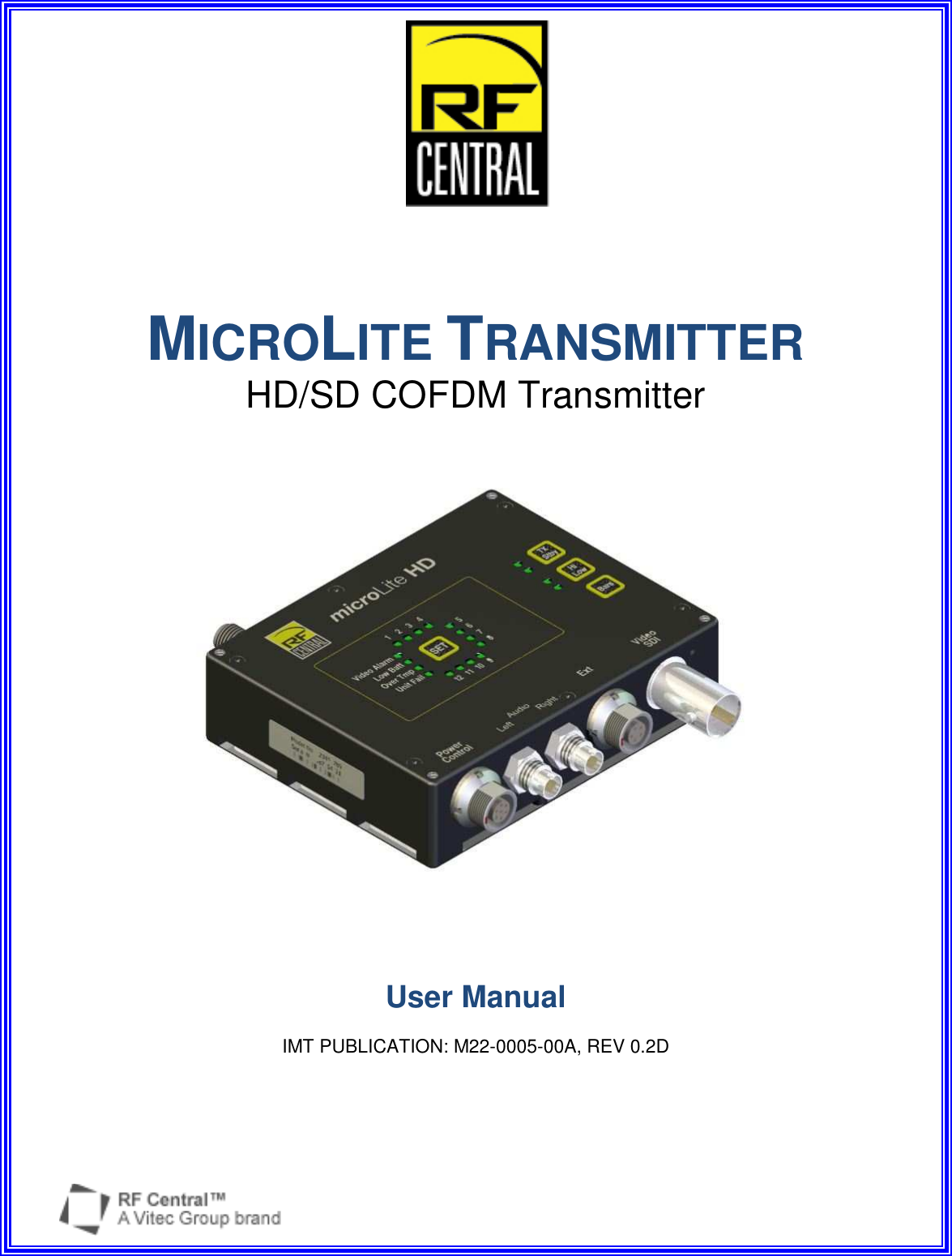
Integrated Microwave Technologies 58MLT MicroLITE HD Transmitter Model NO. 58MLT User Manual M22 0005 00A MLT rev0p2D MANUAL WIP

Integrated Microwave Technologies, LLC. MicroLITE HD Transmitter Model NO. 58MLT M22 0005 00A MLT rev0p2D MANUAL WIP

User manual

       MICROLITE TRANSMITTER HD/SD COFDM Transmitter         User Manual  IMT PUBLICATION: M22-0005-00A, REV 0.2D
MicroLite Transmitter User Manual   Revision 0.2D    2  Revision History  Date  Revision  Modified By  Description May 16, 2011- June 13, 2011  0.0D  DLA(MH)  Initial  release to approvers July 20, 2011  0.1D  DLA / MH  Ongoing updates and clarifications (WIP) August 17. 2011  0.2D  MH  Added regulatory text (FCC and IC)     MICROLITE TRANSMITTER User Manual IMT Publication: M22-0005-00A        IMT, LLC. 200 International Drive Mt. Olive, NJ, 07828, USA. T +1 908 852 3700   F +1 908 813 0399    www.imt-solutions.com          We make every effort to ensure our documentation is as accurate and as complete as possible.  In the event that you find any errors or omissions, please contact Customer Tech Support at (908) 852-3700, or via email a service@nucomm.com.  © Copyrighted 2011 - IMT, LLC - Mount Olive, New Jersey 07828
MicroLite Transmitter User Manual   Revision 0.2D    3    CAUTION!  RISK OF ELECTRICAL SHOCK.  DO NOT REMOVE COVERS.    Do not remove any covers  Refer servicing to qualified technicians only  Disconnect all power before servicing   Read and perform all instructions carefully  Failure to follow suggested instructions and guidelines may void all warranties  PRUDENCE!  RISQUE DE CHOC ÉLECTRIQUE. NE SUPPRIMEZ PAS LES COUVERTURES.    Ne supprimez pas les couvertures  Voir entretien à qualifiés Techniciens seulement.  Déconnectez tous les pouvoir avant l'entretien.  Lecture et effectuer toutes les instructions attentivement.   Échec de suivre les lignes directrices et les instructions proposées peut-être annuler toutes les garanties.
MicroLite Transmitter User Manual   Revision 0.2D    4 FCC CAUTION/ PRUDENCE DE FAC  Any change or modification not approved by the party responsible for compliance could void the user’s authority to operate this device.  This device requires professional installation.   For operation within 5.725 - 5.850 GHz frequency range, the maximum EIRP must be less than 36 dBm. The qualified antenna types to be used with this device include: Low Gain Collinear Omni Antenna (4.5dBi or 6 dBi)  This device complies with Part 15 of the FCC Rules. Operation is subject to the following two conditions: (1) This device may not cause harmful interference, and (2) this device must accept any interference received, including interference that may cause undesired operation.  In order to maintain compliance with the FCC RF exposure guidelines, this device should be installed and operated with a minimum distance of 20cm between the radiator, and the body of the operator and/or nearby persons.  Tout changement ou modification non approuvé par la partie responsable de la conformité pouvait annuler l'autorisation de l'utilisateur pour l'exploitation de ce dispositif.  Ce dispositif nécessite l'installation professionnelle.  Pour l'opération au sein de la gamme de fréquences de 5.725-5.850 GHz, la pire maximale doit être inférieure à 36 dBm. Les types d'antenne qualifiés pour être utilisé avec ce dispositif, citons :  Antenne Omni colinéaires faible Gain colinéaires Omni antenne (4.5dBi ou 6 dBi).  Cet appareil est conforme à la partie 15 des règles de la FCC. Opération est soumis à deux conditions suivantes: (1) ce dispositif ne peut pas causer de brouillage préjudiciable, et (2) ce dispositif doit accepter toute ingérence a reçu, y compris le brouillage qui peut provoquer l'opération non désirée.  Afin de maintenir la conformité avec les directives d'exposition RF FCC, ce dispositif doit être installé et exploité avec une distance minimale de 20 cm entre le radiateur et le corps de l'opérateur ou à proximité de personnes.     FCC STATEMENT This equipment (FCC ID: I4U-58MLT) has been tested and found to comply with the limits for a Class B digital device, pursuant to part 15 of the FCC Rules.  DÉCLARATION DE FAC Cet équipement (FCC ID: I4U-58MLT) a été testé et de respecter les limites pour une classe b dispositif numérique, conformément à la partie 15 des règles de la FCC.
MicroLite Transmitter User Manual   Revision 0.2D    5 IC Notice/:IC Avis 1.  Under Industry Canada regulations, this radio transmitter may only operate using an antenna of a type and maximum (or lesser) gain approved for the transmitter by Industry Canada. To reduce potential radio interference to other users, the antenna type and its gain should be so chosen that the equivalent isotropically radiated power (e.i.r.p.) is not more than that necessary for successful communication.  Conformément à la réglementation d'Industrie Canada, le présent émetteur radio peut fonctionner avec une antenne d'un type et d'un gain maximal (ou inférieur) approuvé pour   l'émetteur par Industrie Canada. Dans le but de réduire les risques de brouillage radioélectrique à l'intention des autres utilisateurs, il faut choisir le type d'antenne et son gain de sorte que la puissance isotrope rayonnée équivalente (p.i.r.e.) ne dépasse pas l'intensité nécessaire à l'établissement d'une communication satisfaisante.  2.  This radio transmitter (IC: 9479A-58MLT) has been approved by Industry Canada to operate with the antenna types listed below with the maximum permissible gain and required antenna impedance for each antenna type indicated. Antenna types not included in this list, having a gain greater than the maximum gain indicated for that type, are strictly prohibited for use with this device.  Le présent émetteur radio (identifier le dispositif par son numéro de certification ou son numéro de modèle s'il fait partie du matériel de catégorie I) a été approuvé par Industrie Canada pour fonctionner avec les types d'antenne énumérés ci-dessous et ayant un gain admissible maximal et l'impédance requise pour chaque type d'antenne. Les types d'antenne non inclus dans cette liste, ou dont le gain est supérieur au gain maximal indiqué, sont strictement interdits pour l'exploitation de l'émetteur.  Antenna Approved/Antenne approuvé Type/Type  Max. Gain/Max. Gain Impedance/Impédance Collinear Omni Antennas/Colinéaires Omni antennes 6 dBi  50 Ω  3.  This device complies with Industry Canada licence-exempt RSS standard(s). Operation is subject to the following two conditions: (1) this device may not cause interference, and (2) this device must accept any interference, including interference that may cause undesired operation of the device.  Le présent appareil est conforme aux CNR d'Industrie Canada applicables aux appareils radio exempts de licence. L'exploitation est autorisée aux deux conditions suivantes : (1) l'appareil ne doit pas produire de brouillage, et (2) l'utilisateur de l'appareil doit accepter tout brouillage radioélectrique subi, même si le brouillage est susceptible d'en compromettre le fonctionnement.  4. In order to maintain compliance with the IC RF exposure guidelines, this device should be installed and operated with a minimum distance of 20 cm between the radiator, and the body of the operator and/or nearby persons.  Afin de maintenir la conformité avec les directives d'exposition RF IC, ce dispositif doit être installé et exploité avec une distance minimale de 20 cm entre le radiateur et le corps de l'opérateur ou à proximité de personnes.
MicroLite Transmitter User Manual   Revision 0.2D    6
MicroLite Transmitter User Manual   Revision 0.2D    7 MICROLITE TRANSMITTER User Manual Contents 1 Introduction ______________________________________________________________________ 10 1.1 Manual Overview _____________________________________________________________ 10 2 MICROLITE Description _____________________________________________________________ 12 2.1 Application Diagram __________________________________________________________ 13 2.2 Theory of Operation  __________________________________________________________ 14 2.2.1 Power, Remote Control, and User Data Interface Connector  ________________________________ 15 2.2.2 Audio and Video Input Connectors _______________________________________________________ 15 2.2.3 User Data Input  _______________________________________________________________________ 15 2.2.4 MPEG4 Encoder (H.264 Part 10) _________________________________________________________ 15 2.2.5 COFDM Modulator  _____________________________________________________________________ 15 2.2.6 RF Transmitter  ________________________________________________________________________ 15 2.3 Remote Control and Firmware  ________________________________________________ 16 2.3.1 Remote Control via Serial Interface ______________________________________________________ 16 2.3.2 Firmware updates ______________________________________________________________________ 16 3 Specifications _____________________________________________________________________ 18 3.1 RF ____________________________________________________________________________ 18 3.2 Modulation Modes ____________________________________________________________ 18 3.3 Video Modes supported _______________________________________________________ 18 3.4 MPEG Encoder ________________________________________________________________ 19 3.5 System _______________________________________________________________________ 19 3.6 Power Requirements  _________________________________________________________ 19 3.7 Environmental ________________________________________________________________ 20 3.8 Physical Specifications ________________________________________________________ 20 3.9 Connectors ___________________________________________________________________ 20 4 Installation _______________________________________________________________________ 22 4.1 Overview _____________________________________________________________________ 22 4.2 Identifying MICROLITE Physical Features and Interfaces  _______________________ 23 4.3 Physical Installation __________________________________________________________ 24 4.4 Connect External Signals  _____________________________________________________ 26 4.4.1 Audio and Video _______________________________________________________________________ 26 4.4.2 Power and Control _____________________________________________________________________ 26 4.4.3 User Data (EXT connector) ______________________________________________________________ 26 4.4.4 ASI In (EXT connector) _________________________________________________________________ 26 4.4.5 ASI Out (EXT connector)  _______________________________________________________________ 26
MicroLite Transmitter User Manual   Revision 0.2D    8 4.5 Antenna Installation __________________________________________________________ 26 4.6 Connector Pin Assignment Information  _______________________________________ 27 4.6.1 Power/Control Connector Pinout _________________________________________________________ 27 4.6.2 Audio Input Connectors Pinout  __________________________________________________________ 28 4.6.3 Ext Connector Pinout ___________________________________________________________________ 28 5 Operation  __________________________________________________________________________ 30 5.1 Power Up the MICROLITE  ______________________________________________________ 30 5.2 Pre-Configure the MICROLITE user options  ___________________________________ 30 5.3 Button and LED Interface _____________________________________________________ 30 5.4 Select User Level Settings  ____________________________________________________ 31 5.5 Put the unit in Transmit Mode _________________________________________________ 32 5.6 Select Power Level  ___________________________________________________________ 32 5.7 Verify Operation ______________________________________________________________ 32 5.8 Using the MICROLITE to Transmit Audio and Video Signals ______________________ 32 5.9 Using the MICROLITE To Transmit User Data  ___________________________________ 32 5.10 Using alternate/custom controllers  ___________________________________________ 33 5.10.1 Serial Interface Rate, Parity, and Stop Bit Specifications  _________________________________ 33 5.10.2 Command and Response Packet Formats_______________________________________________ 33 5.11 Troubleshooting ______________________________________________________________ 34 5.12 Maintenance Information _____________________________________________________ 34  Figures Figure 2-1: Application Diagram, with optional PC. _____________________________________________________ 13 Figure 2-2: Internal Block Diagram ___________________________________________________________________ 14 Figure 4-1: MICROLITE Transmitter User Interface ______________________________________________________ 23 Figure 4-2: MLT Connectors  ________________________________________________________________________ 23 Figure 4-3: Detail of Fan Openings ___________________________________________________________________ 24 Figure 4-4: MICROLITE Outline Drawings (Dimensions in Inches) _________________________________________ 25 Figure 4-5: Power/Control Connector Detail ___________________________________________________________ 27 Figure 4-6: Audio Connector Detail___________________________________________________________________ 28 Figure 4-7: EXT Connector Detail ____________________________________________________________________ 28 Figure 5-1: Control and Monitoring User Interface______________________________________________________ 31  Tables Table 2-1: Summary of High Level Features and Benefits_______________________________________________ 12 Table 3-1: Frequency Band Coverage ________________________________________________________________ 18 Table 3-2: Environmental Specs _____________________________________________________________________ 20 Table 4-1: MicroLite Connectors _____________________________________________________________________ 23 Table 4-2: Power and Control Cables  ________________________________________________________________ 26 Table 4-3: Power/Control Pinout _____________________________________________________________________ 27 Table 4-4: Audio 1 & 2 Pinout  _______________________________________________________________________ 28 Table 4-5: Ext Pinout _______________________________________________________________________________ 28 Table 5-1: Table of Troubleshooting Tips  _____________________________________________________________ 34
MicroLite Transmitter User Manual   Revision 0.2D    9
MicroLite Transmitter User Manual   Revision 0.2D    10 1 Introduction  This document is a user manual for RF CENTRAL’s MICROLITE microwave video transmitter. The MICROLITE is a compact transmitter that digitally encodes video signals and transmits them using COFDM modulation over microwave frequencies using secure methods. The unit accepts either  HD-SDI, SD-SDI, or composite video inputs in NTSC or PAL format, and can also accept User Data (e.g. NMEA GPS sentences) for transmission along with the main input signals.  It has a built in MPEG4 (H.264 part 10 AVC) encoder and COFDM modulator. The MICROLITE is housed in an ultra compact, lightweight enclosure that can be used in harsh environments.  Throughout this manual, the product is referred to as the “MICROLITE”, the “MICROLITE Transmitter”, “MLT”,  “MicroLite TX”, or simply the “transmitter.”  1.1 Manual Overview  The contents of this manual are as follows:  Chapter 2 – Describes the theory of operation and the features of the MICROLITE TRANSMITTER.  Chapter 3 – Contains a list of the MICROLITE TRANSMITTER specifications. The specifications include transmitter feature specifications, power requirements, environmental specifications, and I/O specifications.   Chapter 4 – Explains how to install the MICROLITE TRANSMITTER.   Chapter 5 – Describes operating procedures for the MICROLITE TRANSMITTER. It also contains an overview of the MICROLITE TRANSMITTER programmable serial interface.  The rear of this manual contains warranty and repair information.
MicroLite Transmitter User Manual   Revision 0.2D    11
MicroLite Transmitter User Manual   Revision 0.2D    12 2 MICROLITE Description  This chapter describes the MICROLITE transmitter theory of operation, features, and benefits. It also contains a block diagram of the MICROLITE transmitter circuitry and a typical application example.   The MicroLite Transmitter has external connectors and features direct plug-in compatibility with off the shelf equipment using industry standard interfaces.  The MICROLITE Transmitter internal circuitry compresses the audio and video signals, and organizes the compressed data into ISO digital video transport streams. The transmitter uses COFDM modulation and transmits at microwave frequencies in the specific band(s) supported by the unit.  Though the unit ships pre-configured, a graphical user interface that runs on a PC is available to modify the operating parameters. Optionally, custom software written to implement the RS232 command set may be used. Refer to Chapter 5, “Operation” for more information.  IMT has the ability, should the need ever arise, to provide the user with firmware files and instructions for local firmware installation, such as for feature upgrades, etc.  Table 2-1: Summary of High Level Features and Benefits  Feature  Benefit COFDM Microwave Digital Video Transmitter  Microwave output frequencies in multiple bands.   Multiple Output Frequencies  User orderable frequency band options.  User programmable channels and offsets within band.  ASI, HD-SDI, and SD-SDI Inputs  Compatible with advanced video cameras. NTSC or PAL Composite Video Inputs  Compatible with industry standard SD video cameras.  Stereo Audio Line Inputs  Direct audio input option for use with video signals that do not contain embedded audio. MPEG4 (H.264 Part 10) Encoder  Industry standard compliant video compression.  Implements latest algorithms for high quality.  User Data Channel  Data can be transmitted along with audio and video to the receiver.  Remote Control GUI for Programming the MicroLite Convenient menu and button based graphical user interface for Windows PC’s.  Can be used to program the preset settings on the top panel. GUI uses MicroLite RS-232 remote control serial port. Compact Housing  Fits in small form factor applications.  Operates in Harsh Environments  Can be used at both high and low temperature and humidity.
MicroLite Transmitter User Manual   Revision 0.2D    13 2.1 Application Diagram  Typically the MicroLite Transmitter is simply camera mounted.  However, more complex applications are possible per user requirements.  Figure 2-1 shows a non-typical MICROLITE Transmitter application, which includes a PC for configuration.      The MICROLITE TX may be programmed by a PC or host processor while connected in the application, or it may be pre-configured and installed in the application without any programming required during operation. The latter approach can save expense in cost sensitive applications.   Commonly used configurations can be set up and stored in the MICROLITE memory as “preset” configurations. Up to 12 presets can be stored. Once presets have been stored, configurations can be recalled using the front panel as well as the program interface.     Figure 2-1: Application Diagram, with optional PC.
MicroLite Transmitter User Manual   Revision 0.2D    14 2.2 Theory of Operation  Major blocks in the MICROLITE TX include:  • Video Input Interfaces - ASI or HD-SDI, SD-SDI; NTSC or PAL • Stereo Audio Input Interface • MPEG4 Video Compression Circuit • COFDM Modulator • Microwave Transmitter and Antenna Connector • Programmers Serial Interface for Remote Control Purposes • Internal Microprocessor and Memory • Power Circuitry     Figure 2-2: Internal Block Diagram
MicroLite Transmitter User Manual   Revision 0.2D    15 2.2.1 Power, Remote Control, and User Data Interface Connector The MicroLite Transmitter Power, Remote Control, and User Data interface includes power and ground connections plus two RS-232 serial port interfaces.  2.2.2 Audio and Video Input Connectors The MICROLITE TX has two analog audio inputs that can be used for stereo audio and HD/SD-SDI or  NTSC/PAL video input. Refer to Chapter 3 for specifications of these signals. 2.2.3 User Data Input A data channel may be transmitted along with the audio and video information. The data channel is accessed through a RS-232 serial interface in the EXT connector.   Examples of supported User Data may include NMEA GPS sentences and simplex RS232. 2.2.4 MPEG4 Encoder (H.264 Part 10) The MLT compresses the input video signal before modulation and transmission to reduce bandwidth. The MICROLITE TX contains a built-in MPEG4 (H.264 part 10) encoder for this purpose. The MicroLite TX features the latest compression methods utilizing B frames for more accurate encoding of compressed video signals.  2.2.5 COFDM Modulator  The COFDM modulator receives data from the output of the MPEG4 AVC encoder through a circuit that enhances the security of transmissions.  The MICROLITE TX is able to transmit data at high data rates and with low error rates using COFDM modulation techniques. The data rate used by the transmitter depends upon the CODFM modulator settings used.  Refer to Chapter 5, “Operation” for more information. 2.2.6 RF Transmitter The MICROLITE microwave transmitter circuits mix the signal to the desired microwave frequency. The signal is filtered and boosted through a low noise output amplifier.   The MICROLITE TX has a single SMA style antenna connector. The output impedance of the antenna connector is 50 ohms.   Note: On 5.8GHz models, the connector is RP-SMA due to FCC requirements.  Refer to Chapter 3, “Specifications” for frequency band and channel tuning specifications.
MicroLite Transmitter User Manual   Revision 0.2D    16 2.3 Remote Control and Firmware 2.3.1 Remote Control via Serial Interface An RS-232 command set is implemented to allow remote control of all configuration options, as well as monitoring of internal status and settings.  Commands and responses are sent via the RS-232 serial interface located on the Power/Control connector.    Our “Nano Controller” GUI is available for controlling the unit via the RS-232 serial interface. Any Windows compatible computer running Windows XP or Vista with 500 MB of memory and 1 GHz Pentium or above can be used.  Refer to Chapter 5, “Operation” for more information.    Optionally, users can create custom control interfaces as required to suit their applications. The RS-232 command set, or “remote protocol”, is available upon request for this purpose. 2.3.2 Firmware updates  The unit firmware may be updated via the USB interface on the Power/Control connector, using our NanoTx Programmer software.  A programming cable (IMT part number 922-B963-01A-R, or equivalent) is required. Contact IMT Tech Support for additional details.
MicroLite Transmitter User Manual   Revision 0.2D    17
MicroLite Transmitter User Manual   Revision 0.2D    18 3 Specifications 3.1 RF Table 3-1: Frequency Band Coverage Base Part Number Frequency (GHz) RF Power (dBm) DC Power (W) 23MLT-23-U3-C3 2.200-2.400 23 13 58MLT-20-U3-C3 5.725-5.850 20 15  Tuning step size  ........................................................ 1 MHz step size Frequency stability ..................................................... ± 10ppm  Standby mode ............................................................  No RF output Normal  ...................................................................... Instant on-frequency transmission 3.2 Modulation Modes Modulation 1 • Format: ........................................................... COFDM (DVB-T) • Carriers: ......................................................... 2K • Constellation: ................................................. QPSK, 16QAM • Code Rate: ..................................................... 1/2, 2/3, 3/4, 5/6, 7/8 • Guard Interval: ............................................... 1/32, 1/16, 1/8, 1/4  • Bandwidth: ..................................................... 6 MHz, 8 MHz 3.3 Video Modes supported  Video Mode  Supported HD-SDI Formats 1080i/60  NO    1080i/59.94  Yes  1080i/50  YES     1080/25p  NO    1080/24p  YES   1080/23.98p  YES   1080/23.98pSf  NO    720/60p  NO  720/59.94p  YES  720/50p  YES    720/24p  YES   720/23.98p  YES  SD-SDI Formats  NTSC  YES  PAL  YES Composite NTSC  Yes  PAL  Yes
MicroLite Transmitter User Manual   Revision 0.2D    19 3.4 MPEG Encoder Standard ................................................................... MPEG-4 Part 10 / H.264 AVC Video • Video Coding ................................................. AVC • Video Input: ................................................... Composite   • NTSC:  ........................................................... 720 x 480(4:2:0)  • PAL:  .............................................................. 720 x 576(4:2:0) • SD-SDI input: ................................................ ANSI/SMPTE 259M  • HD-SDI Input: ............................................... ANSI/SMPTE 292M  Audio • Audio Coding: ............................................... ISO/IEC 11172-3(Layer II) • Audio Sample Rate: ....................................... 48Khz • Audio Channels:  ........................................... 1 Stereo, 2Mono Standard • Audio Input: ................................................... Line; Single ended 1Vp-p (nom.) into 10K Ohms                                                                                                                              (-12dB to +50dB gain)   ................................................................................... Mic, (-12dB to +50dB gain); 10K Ohms                                                                                      5v Phantom power or Ext. Bias   ................................................................................... De-embedded from SDI  • Tone  .............................................................. (-10dBfs/8dBm)  Level Adj. (-10-26dBfs)  3.5 System • Video Present: ................................................ Remote Standby/Test Generator Selectable • Test Generator (Dynamic):  ........................... SMPTE CB(NTSC)/100% CB(PAL)  16 Character ID (Match SDT Service name)  • 1.0 and 1.2kHz Tones • ASI input:....................................................... Rate converted from 0mpbs-Max modulation rate  • PCR Retime stamp • User Data: ...................................................... RS232 Side channel  (300-115K Baud) • Remote Control: ............................................. RS232 • Local Control: ................................................ Key Board 3.6 Power Requirements • Input range: DC: ............................................  +9 to +18 • Power consumption:  ..................................... See table above
MicroLite Transmitter User Manual   Revision 0.2D    20 3.7 Environmental Table 3-2: Environmental Specs Item  Specification Temperature Range, Operational, Bottom Surface –10° to +50°C (Base plate temperature. The bottom surface of the MICROLITE must be maintained within the temperature range listed here.) Temperature Range, Storage  –40° to +80°C Humidity  0% to 95% RH, non-condensing Altitude, Operating  20,000ft (6,000m) maximum Altitude, Storage  50,000ft (15,000m) maximum  3.8 Physical Specifications Size:  .......................................................................... 3.06”  x 0.8” x 2.44”  (excluding connectors) Volume:  .................................................................... 3.51  in3 Weight:  ..................................................................... 0.16 lbs (73 g) 3.9 Connectors • Power, RS232 Control: L .............................. Lemo, 7 pin  • BNC Input: .................................................... Composite, HD-SDI, SD-SDI, or ASI Input • Left and Right Audio:  ................................... 4pin Telocate  • ASI Input B, ASI Output, User Data:  ........... Lemo, 5 pin • RF Output:  .................................................... 50 Ohm RP-SMA (due to FCC requirement)  Connector Part Numbers: 5 pin Lemo (on TX) ................................................... ECG.0B.305.CLN IMT PN .......................................................... 512-F3022-005-R 5 pin Lemo (mating) .................................................. FGG.0B.305.CLAD52 IMT PN .......................................................... 512-F3022-005-R 7 pin Lemo (on TX) ................................................... ECG.0B.307.CLN IMT PN .......................................................... 512-F3022-007-R 7 pin Lemo (mating) .................................................. FGG.0B.307.CLAD52 IMT PN .......................................................... 512-F3022-007-R
MicroLite Transmitter User Manual   Revision 0.2D    21
MicroLite Transmitter User Manual   Revision 0.2D    22 4 Installation  This chapter contains steps for installing the MicroLite transmitter in typical environments where it may be used. 4.1 Overview  The MICROLITE Transmitter is typically camera mounted in a standalone system containing onlya camera and power supply. MICROLITE applications may also contain a host processor that is used in the field to re-configure settings.
MicroLite Transmitter User Manual   Revision 0.2D    23  4.2 Identifying MICROLITE Physical Features and Interfaces      Figure 4-1: MICROLITE Transmitter User Interface    Figure 4-2: MLT Connectors  Table 4-1: MicroLite Connectors Connector (from left above)   Label on Unit   Description Lemo 7 pin  Power & Control  Power, USB, RS-232 Remote Control Interface Telocate  Audio Left  Audio Line Input Telocate  Audio Right  Audio Line Input Lemo 5 pin  Ext  ASI input, ASI Output, User Data, and USB  BNC  Video & SDI  Composite NTSC or PAL Input, HD-SDI, SD-SDI Input
MicroLite Transmitter User Manual   Revision 0.2D    24  ______________________________________________________________  ! WARNING – DO NOT OPEN THE MICROLITE   The MICROLITE Transmitter contains no user serviceable parts. Do not open the MICROLITE housing. Failure to comply will result in voiding of the warranty.  ______________________________________________________________  4.3  Physical Installation  Note: The MicroLite Transmitter is typically camera mounted in a standalone application, however mounting in a more complex rig or housing may be desired per individual requirements.  In such cases, the user should be aware that the MLT is configured via the programmable serial interface. Should you desire to program the unit while in your application, then you r application design must provide a means to connect to the serial interface.   If your application cannot support a means to connect to the serial interface, then you must pre-configure the unit prior to installation.  Refer to Section 5.  The MICROLITE TX can be mounted using the four screw holes located on the corners of the housing, using four #2-56 screws. Tighten the four screws gradually in rotation, without applying excess force on one before starting the others.   The MICROLITE TX requires installation using proper thermal dissipation methods. During operation, energy isdissipated to the outside environment, especially on the lower surface of the MICROLITE TX.  The bottom surface of the MicroLite TX must be kept at a temperature within the operating temperature range specified in Chapter 3.   The unit has an internal fan and the fan openings must not be blocked.     The unit should not be operated inside another enclosure unless sufficient cooling is provided that the case temperature is within the range specified in Chapter 3.            Figure 4-3: Detail of Fan Openings   Fan Openings (on all sides of unit)
MicroLite Transmitter User Manual   Revision 0.2D    25  Figure 4-4: MICROLITE Outline Drawings (Dimensions in Inches)
MicroLite Transmitter User Manual   Revision 0.2D    26 4.4 Connect External Signals The MICROLITE connectors include the following major interfaces: • Power and Ground Plus RS-232 programming interface • Video Input Connector  Accepts Composite Video, ASI, or SDI with appropriate cables. • Analog Audio 1 and 2 Line Inputs • User Data 4.4.1 Audio and Video Connect a video source to the appropriate video input. Connect audio sources to the two analog audio line inputs.  4.4.2 Power and Control Connect an appropriate DC power source to the Power/Control connector. The power source requirements are listed in Chapter 3, Specifications.     The Power/Control connector also includes an RS-232 interface for connection to a PC or host processor for programming the unit.  A cable that supports both power and control is required in order to program or pre-configure the unit.    IMT has multiple cables to enable flexibility.  Any Source cable may be used with any Input cable.  Table 4-2: Power and Control Cables IMT part #  Cable Description  CableType 922-B964-01A-R    7pin LEMO to Tamiya Male connector  Input cable 922-B962-01A-R    7pin LEMO to Tamiya Male connector, w/DB9  Input cable (w/Control) 922-B973-01A-R   Anton Bauer D-tap to Tamiya Female connector  Source cable 904-P088-00A-R   12vDC Power Supply with Tamiya Female connector Source cable 4.4.3 User Data (EXT connector) If required, connect suitable User Data input cable to EXT.  Cables are available from IMT.  4.4.4 ASI In (EXT connector) If required, connect suitable ASI input cable to EXT.  IMT part# 921-B379-01A-R (or equivalent) 4.4.5 ASI Out (EXT connector) If required, connect suitable ASI output cable to EXT.  IMT part# 921-B380-01A-R (or equivalent) 4.5 Antenna Installation Connect a suitable antenna directly to the SMA antenna connector, or via a suitable 50 ohm cable.  Before applying power: Ensure proper antenna termination on RF output.
MicroLite Transmitter User Manual   Revision 0.2D    27 4.6 Connector Pin Assignment Information 4.6.1 Power/Control Connector Pinout  Table 4-3: Power/Control Pinout Pin  Function  Notes 1  +12VDC   2  RS232 RX   3  USB DM   4  USB DP   5  RS232 TX   6  USB POWER   7  GROUND     Figure 4-5: Power/Control Connector Detail
MicroLite Transmitter User Manual   Revision 0.2D    28 4.6.2 Audio Input Connectors Pinout Table 4-4: Audio 1 & 2 Pinout  Pin  Function  Notes 1  LINE SELECT   2  +5V MIC BIAS   3  AUDIO IN  Audio line input. 4  GROUND  Connected internally to signal & chassis ground   Figure 4-6: Audio Connector Detail  4.6.3 Ext Connector Pinout Table 4-5: Ext Pinout  Pin  Function  Notes 1  GROUND   2  ASI OUT   3  RX UserData  User Data INTO the unit 4  TX UserData  Not connected for User Data transmission 5  ASI IN      Figure 4-7: EXT Connector Detail
MicroLite Transmitter User Manual   Revision 0.2D    29
MicroLite Transmitter User Manual   Revision 0.2D    30 5  Operation  While this chapter contains basic information about the operation of the MicroLite transmitter, the programming of the unit (including preset configuration) via the Nano Controller GUI is not covered.  Please refer to the “Nano Controller” manual (IMT Publication: M27-0001-00A) for detailed information on how to program and configure the unit.  In this chapter you will find info on how to use the MicroLite transmitter to transmit video, audio, and user data. At the end of the chapter you will find troubleshooting and maintenance information.   5.1 Power Up the MICROLITE    Before applying power: Ensure proper antenna termination on RF output connector.   Turn on the power to the overall system.   Note: The MICROLITE requires up to 20 seconds to complete its internal power up sequence. Supply current will jump up in steps as internal circuits are powered. The final DC supply current will settle after 20 seconds.  The front panel led’s do not lite until the power-up sequence is complete.  5.2 Pre-Configure the MICROLITE user options  The MICROLITE has a wide range of programmable settings.  Before using the MICROLITE in your application, you should pre-configure it to for the settings you want to use in your application.  Settings are selected and configured using the Nano Controller software, or custom third party alternatives.  Please refer to the Nano Controller documentation for details, or contact IMT Technical Support.  5.3 Button and LED Interface   The MicroLite has several Buttons and LED’s on the front panel, which are used to perform basic operation and view basic unit status.  Any changes made via a remote control interface will be reflected by the front panel LED’s.
MicroLite Transmitter User Manual   Revision 0.2D    31   Figure 5-1: Control and Monitoring User Interface    Buttons:  SET  Advances the unit through the presets.  The 1-12 LED’s indicate in GREEN which preset is currently active.  TX  / STBY  Toggles between Transmit and Standby modes.  The appropriate LED is lit.  HI / LOW  Toggles between High and Low Power modes.  The appropriate LED is lit.  LED Off  Toggles all front panel LED’s OFF/ON  In addition to those mentioned  above, the following LED indicators are provided.   ALARM Indicators:    Video Alarm  The #16 LED will display SOLID YELLOW.  Low Battery  The #15 LED will display SOLID YELLOW.  Over Temp  The #14 LED will display SOLID YELLOW.  Unit Fail  The #13 LED will display SOLID YELLOW.  5.4 Select User Level Settings   By use of the SET button, select an appropriate preset so that your MicroLite transmitter and suitable receiver are on the same RF and modulation settings.
MicroLite Transmitter User Manual   Revision 0.2D    32 5.5 Put the unit in Transmit Mode   Press the TX / STBY toggle button to put the unit in Transmit mode.  Pressing the button again will put the unit in Standby mode (no RF output).   5.6 Select Power Level   Press the HI / LOW toggle button to select the power level desired.  In HI mode, the unit will output its full rated power.  In LOW mode, the output will be approximately 6dB  down from the HIGH power output.   5.7 Verify Operation   Verify operation of the MICROLITE by one of the following methods:  (1) If your system contains a host processor capable of communicating with the MICROLITE via the serial interface, use interrogation commands to check the status of the MICROLITE.   (2) Detect the transmitted signal using a spectrum analyzer.  (3) Using an appropriate receiver, verify that you are receiving audio and video from your application setup.  5.8 Using the MICROLITE to Transmit Audio and Video Signals  The MICROLITE uses a COFDM modulation scheme. Receiver systems used with the MICROLITE must be compatible and capable of receiving the type of video transport streams transmitted by the MICROLITE.  Compatible receivers include the RF Central MicroLite Receiver, the IMT SRx Receiver and certain other IMT products. Contact IMT for more information.   When no video signal is present, the MICROLITE enters “Standby Mode.” When a video signal is present, the MICROLITE automatically exits “Standby Mode” and resumes transmission. Standby mode status is indicated on a faceplate user interface LED.  5.9 Using the MICROLITE To Transmit User Data  The User Data Interface can be used to packetize user data along with the main audio and video information. The User Data can be received and output by compatible receivers, such as the MLR and SRx (e.g.). The user data interface must be programmed using the MICROLITE programmable serial interface.
MicroLite Transmitter User Manual   Revision 0.2D    33 5.10 Using alternate/custom controllers   The implementation of an RS-232 command set, or Remote Protocol, allows the use of customized interfaces to perform virtually all unit operations, including:   • Configure Settings • Query Status  The Remote Protocol consists of command and response messages, or packets. The internal CPU handles interpretation of the packets to set unit parameters, and provide responses back through the serial interface.  In addition to IMT’s Nano Controller, alternate control interfaces may be developed, or available from third parties. Additionally, commands and responses may be entered and viewed manually using a command terminal.    The Remote Protocol is available upon request from IMT. 5.10.1 Serial Interface Rate, Parity, and Stop Bit Specifications  Refer to the Remote Protocol for information about the baud rate, number of data bits, stop bits, and flow control methods.  5.10.2 Command and Response Packet Formats  This section provides a brief introduction to the serial interface command and response packet formats.  The command packets use the following format:  NU <tt> <ss><##><cc><dd><CS><CR><LF>  Where the fields are ASCII and are defined as follows:  NU Literal <tt> Address of target (0x01 – 0xFF) <ss> Address of source (0x00 – 0xFF) <##> Packet Length (Packet Length = Command Length + Data Length) <cc> Command (0x00-0xFF) – Different values are used for each command. <dd> Data (Hex Format) – Data values are encoded with a variety of meanings. <CS> (1’s complement of <tt> to end of data) <CR> Carriage Return <LF> Line Feed  After a command packet is received, the unit returns a response packet. Response packets have the same basic format as command packets, except that the source and destination are reversed, and the command field specifies the type of response being sent.
MicroLite Transmitter User Manual   Revision 0.2D    34 5.11 Troubleshooting   Table 5-1: Table of Troubleshooting Tips  Problem  Possible Explanations  Actions to Take No video No Power  Check power source Camera Malfunction  Try a different camera Possible Receiver system issue  Verify that all modulation parameters match at transmitter and receiver.  Video Signal Reception Poor  Receiver not properly positioned Try improved location MICROLITE Programmable Serial Interface Does Not Respond No Power  Check power source Host processor GUI settings issues Verify that the host processor running a GUI interface for programming the MICROLITE is setup and operating correctly.   5.12 Maintenance Information   Follow these procedures when maintaining the device: • Dry the device immediately if it comes into contact with water or other liquids.  Warranty does not cover liquid damage.    • Do not submerge the device or use it directly in rain. • Use ESD Precautions whenever handling the device • Do not touch electrical connections. • Do not open the device. This voids the warranty.  • Keep the device clean by wiping with a soft, dry cloth.  If necessary, dampen only using a solution suitable for cleaning electronic devices.  Warranty does not cover cleaning damage.
MicroLite Transmitter User Manual   Revision 0.2D    35
MicroLite Transmitter User Manual   Revision 0.2D    36 Proprietary Information and Disclaimer Notice  All information and graphic images contained within this manual are the sole property of IMT, LLC, and are issued in the strictest of confidence.  This material may not be reproduced, stored, copied, or converted in any form, nor shall it be disclosed to others or used for manufacturing or any other purpose without the written permission of authorized IMT personnel.    IMT has made every effort to ensure the accuracy of this material at the time of printing.  However, as the specifications, equipment, and this manual are subject to change without notice, IMT assumes no responsibility or liability whatsoever for any errors or inaccuracies that may appear in this manual, or for any decisions based on its use. This manual is supplied for informational purposes only and should not be construed as a commitment by IMT.  Warranty  Equipment manufactured by IMT, LLC is warranted to meet all published specifications and to be free from defects  in  material  and  workmanship  within  a  period  of  two  years  from  date  of  original  shipment.    The company’s liability under this warranty is limited to:  • Servicing or adjusting equipment.     • Replacement of defective parts.  Any equipment returned to the factory shall have the freight paid for by the buyer.  Equipment showing damage by misuse, abnormal conditions of operation, or attempts to repair by other than authorized service personnel shall be excluded from this warranty.  IMT shall in no event be responsible for incidental injury or property damage.  Since IMT has no control over conditions of use, no warranty is made or implied as to suitability for the customer’s intended use, beyond such performance specifications as are made part  of  the  purchase  order.    There  are  no  warranties  expressed  or  implied,  except  as  stated  herein.    This limitation on warranties shall not be modified by verbal representations.  Shipping Damage  Equipment shipped FOB IMT shall become the property of buyer upon delivery and receipt from carrier.  Any damage in shipment should be handled by the buyer directly with the carrier.  Immediately request the carrier’s inspection upon evidence of damage in shipment.  Field Service  IMT products are designed with easy access to components to facilitate service.  However, some modules cannot be service in the field. To prevent voiding of the warranty, please contact Tech Support before servicing or making any repairs.  The user is cautioned to read all module descriptions in this manual.  Warnings are included in the circuit descriptions and on certain modules themselves.    Replacement Modules Troubleshooting to the component level is often not cost-effective and frequently impossible.  Often the practical method of effecting repairs is to substitute known good spare modules for suspect units.  Replacement modules for our standard product line are usually available.
MicroLite Transmitter User Manual   Revision 0.2D    37 Technical Support Information   Technical Support personnel are available to extend technical assistance to customers while installing, operating, or troubleshooting IMT equipment. Please have your model number and serial number available.  Telephone During IMT business hours, 8:30am - 5:30pm EST (-5 Hours, GMT), call: US ........................................................... 908-852-3700 International ............................................ 001-1-908-852-3700 After hours, call: US or International .................................. 888-531-3892 Email  Email address ....................................................... service@nucomm.com Internet Web address ......................................................... www.imt-solutions.com  Equipment Returns If equipment cannot be successfully restored through telephone consultation, return to the factory may be required. Loaner items may be available until the repaired items are returned.   For out-of-warranty equipment only: We evaluate all returned units, and then confers with the client on corrective action.  If no fault is found, or no corrective action is authorized, a diagnostic fee may be charged.  Prior to returning products to the factory, please obtain a return material authorization (RMA) number and shipping instructions from Tech Support.   When returning equipment, it is very helpful to enclose a note containing the following: • RMA number. • Serial number. • A detailed description of the problem. • Name of an engineer or technician we may contact regarding problems encountered.   • A “ship to” and “bill to” address.  Ship all returns to: IMT, LLC Attn: RMA# (your RMA number) 200 International Drive  Mt. Olive, NJ, 07828, USA (908) 852-3700  For International returns: In addition to the instructions above, when shipping internationally we recommend the use of a courier such as Federal Express, UPS, etc, and that the goods be shipped DOOR-TO-DOOR PRE-PAID.  This will reduce Customs costs, handling charges and delays.  Enclose all the information above, plus a statement that the equipment was manufactured in the United States (the latter is needed to expedite customs processing).
MicroLite Transmitter User Manual   Revision 0.2D    38                      IMT, LLC. 200 International Drive Mt. Olive, NJ, 07828, USA. T +1 908 852 3700   F +1 908 813 0399    www.imt-solutions.com

Navigation menu