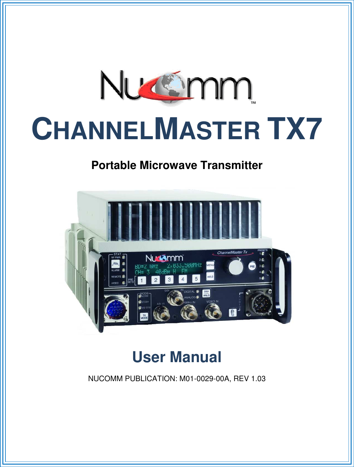
Integrated Microwave Technologies TRICMTX7 Tri-Band ChannelMaster Transmitter TRICMTX7 User Manual M01 0029 00A CMTX7 rev1p03 MANUAL

Integrated Microwave Technologies, LLC. Tri-Band ChannelMaster Transmitter TRICMTX7 M01 0029 00A CMTX7 rev1p03 MANUAL
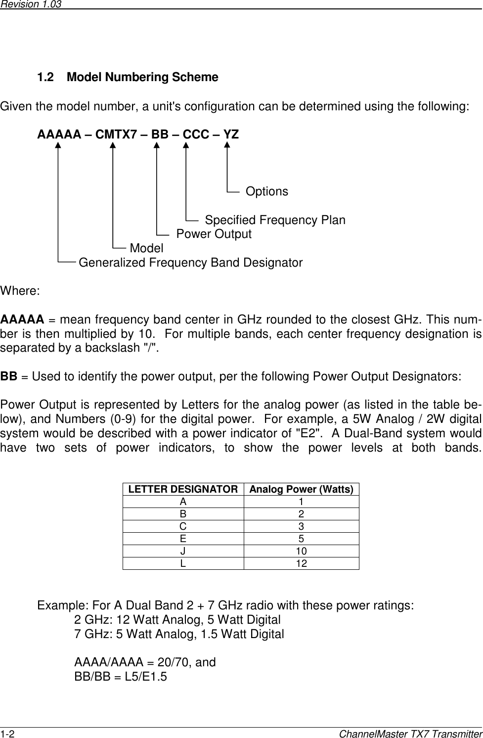
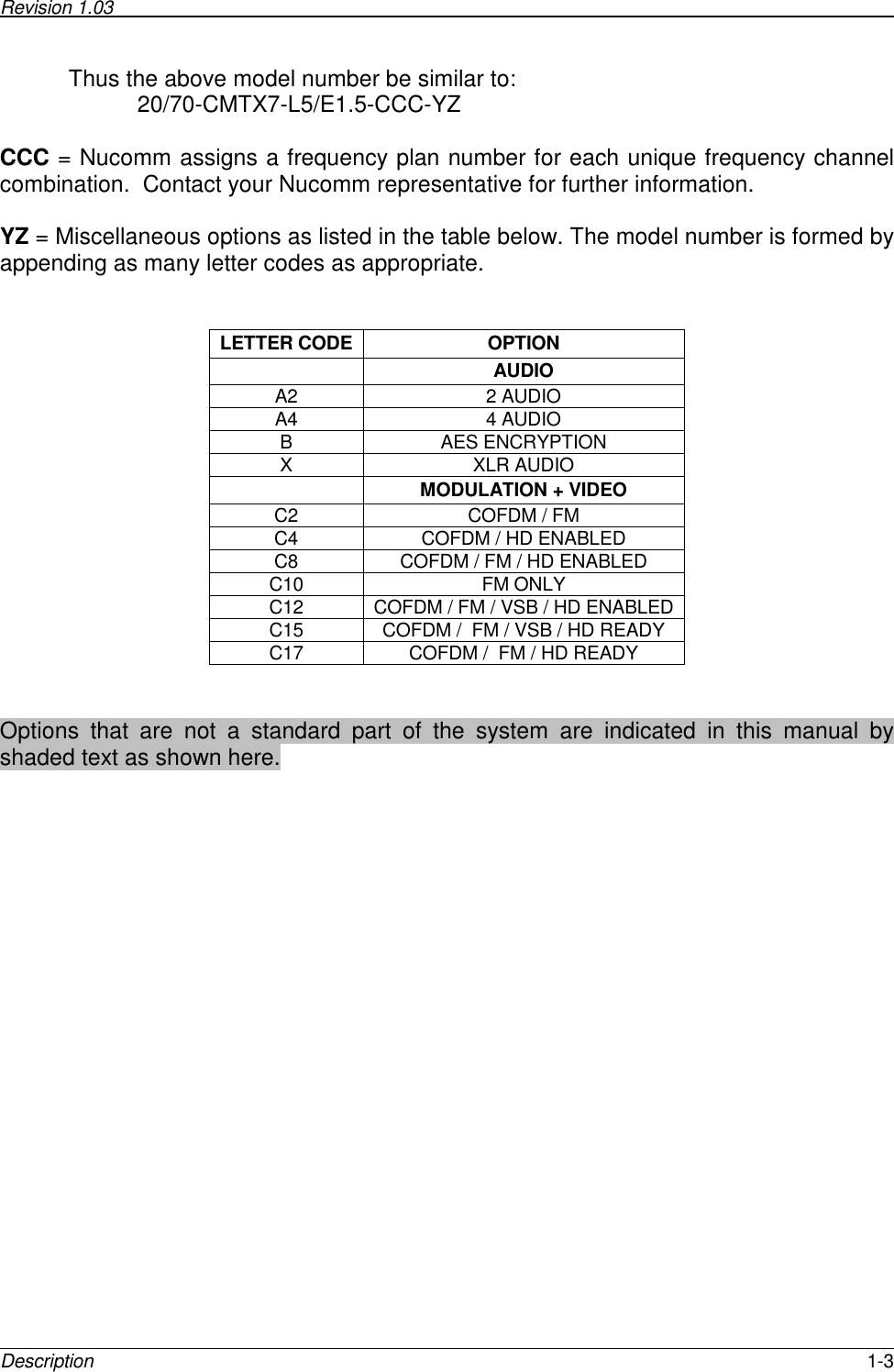
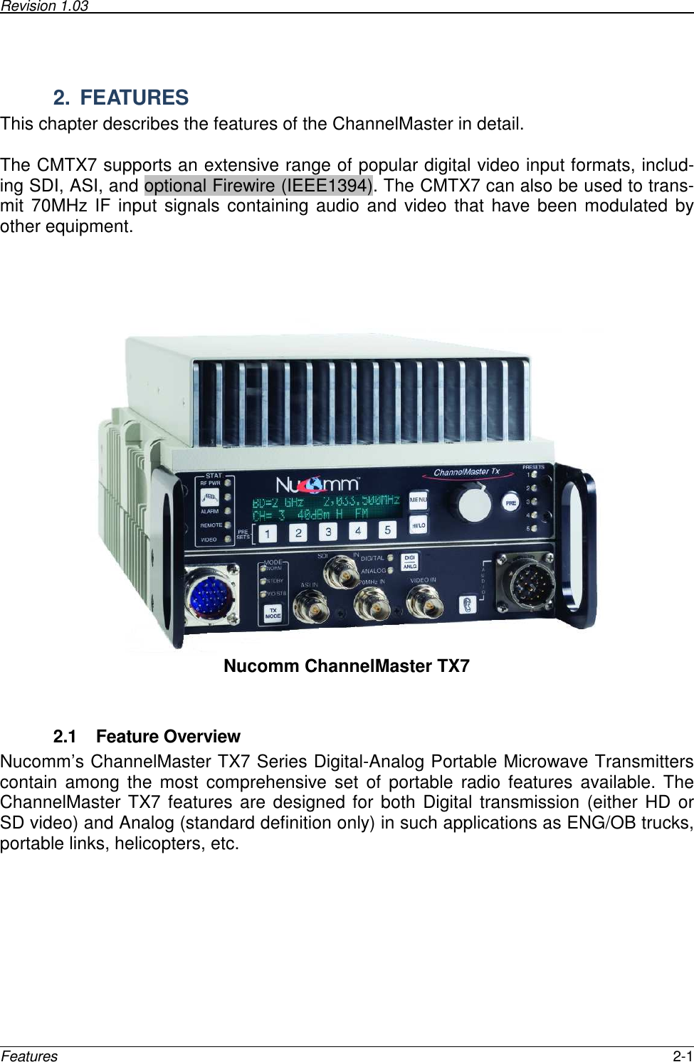
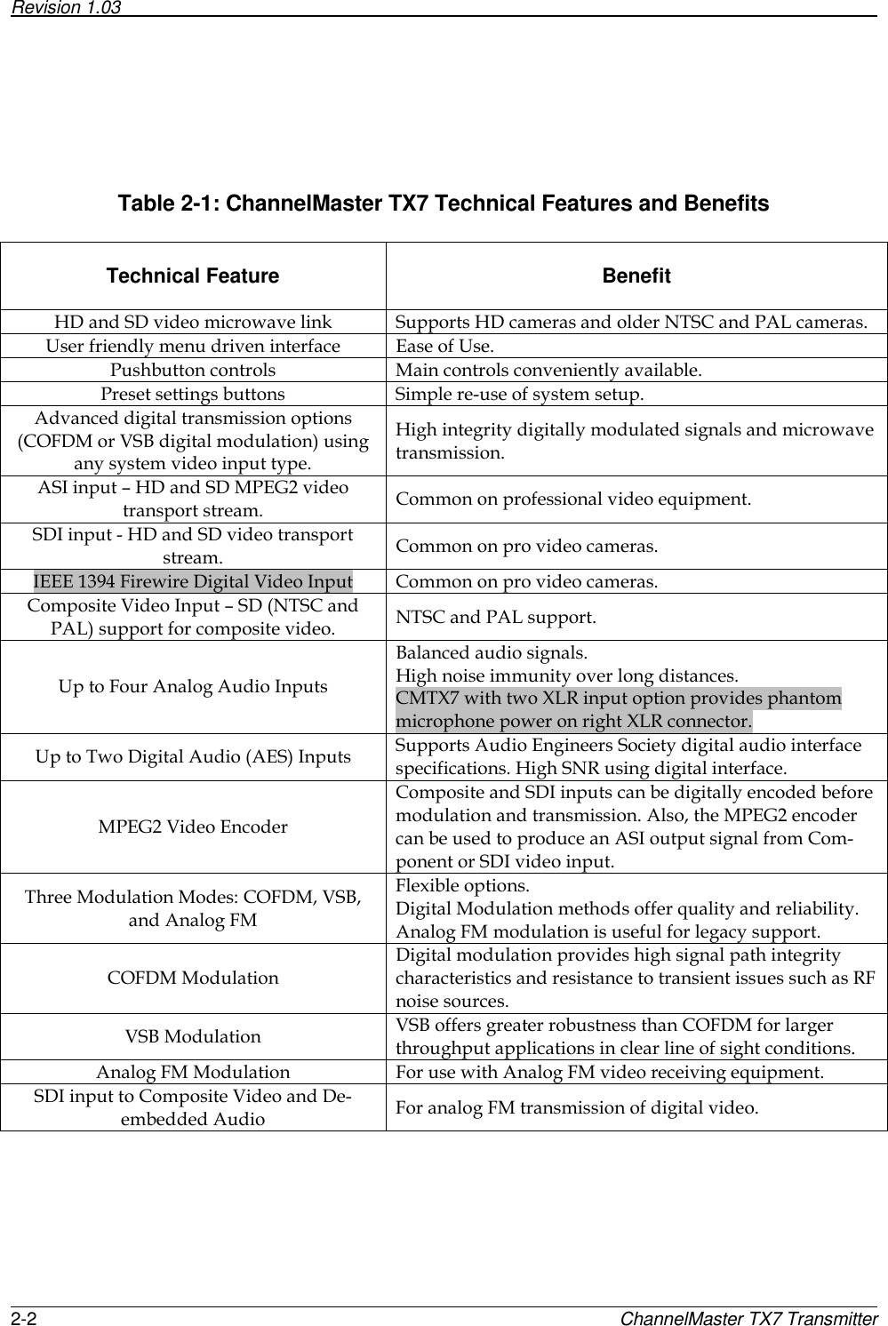
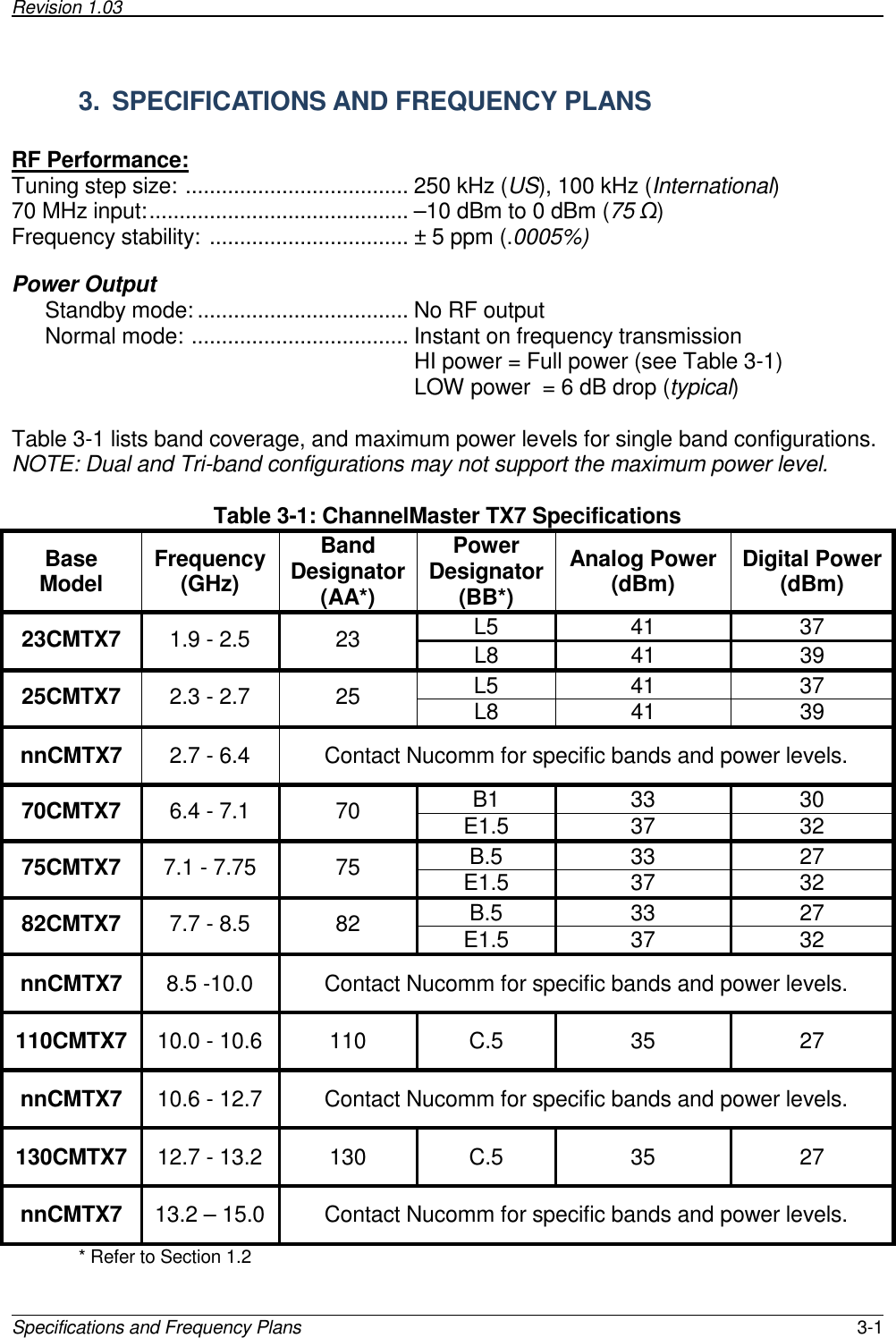
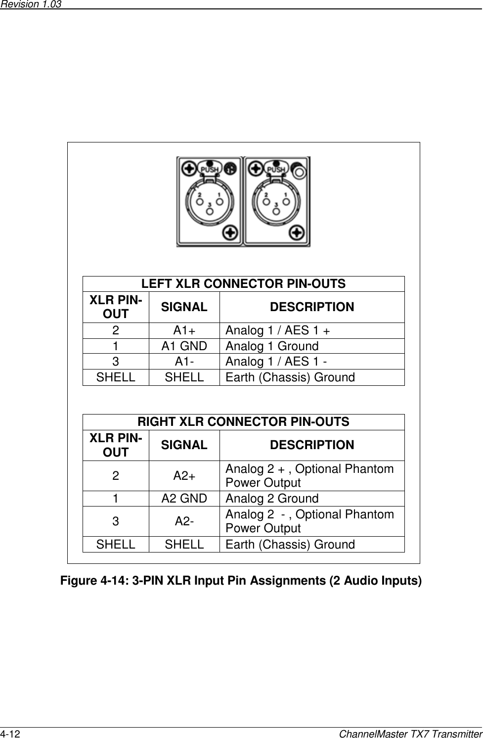
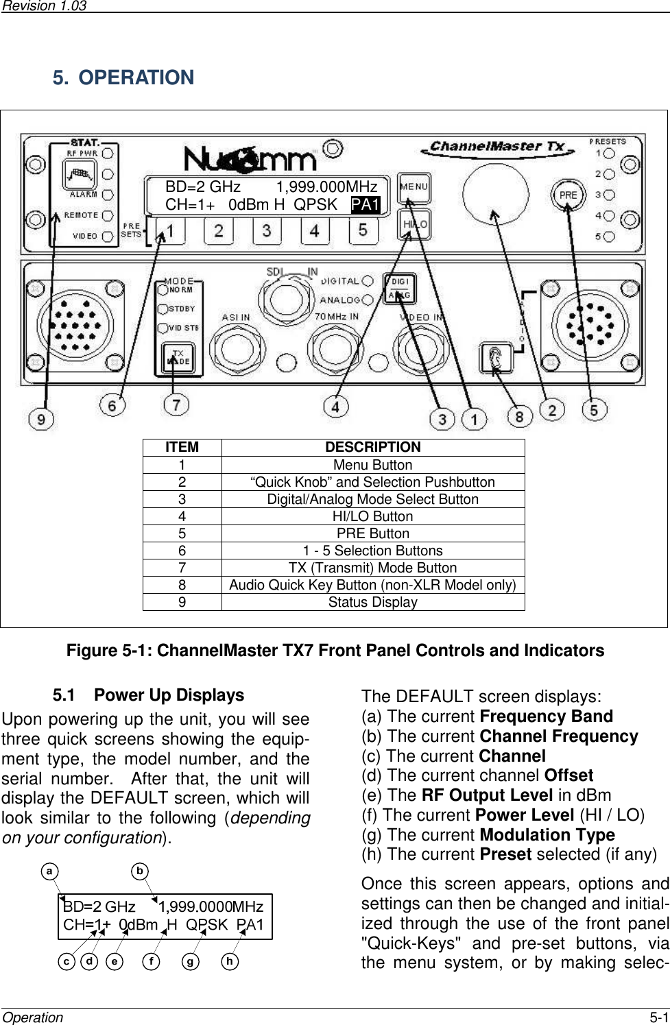
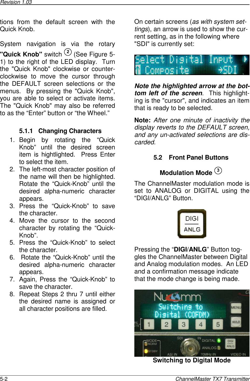
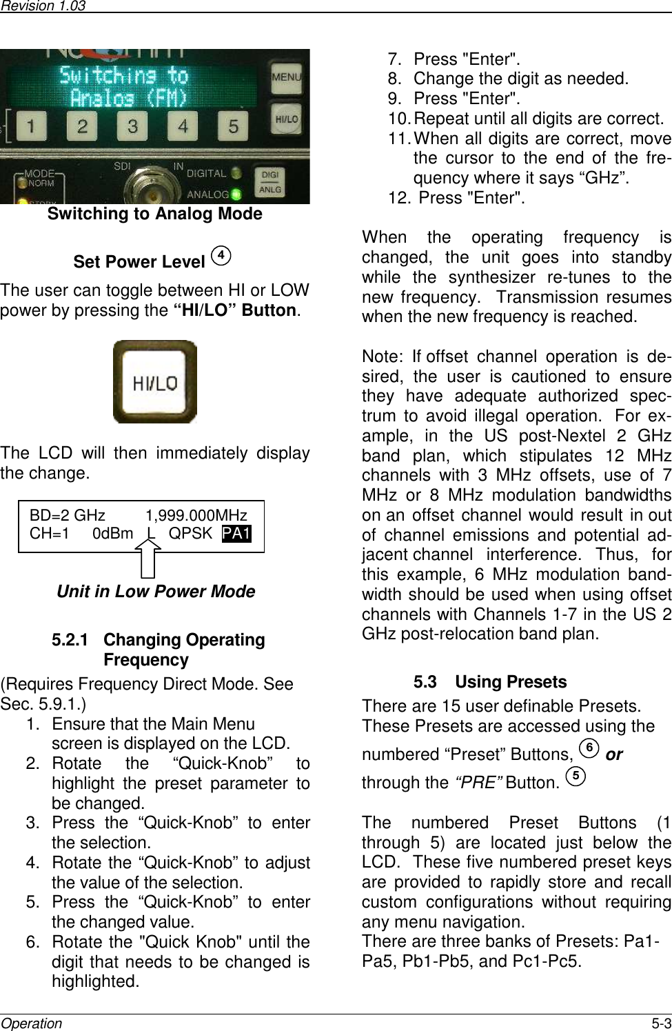
Manual

        CHANNELMASTER TX7  Portable Microwave Transmitter    User Manual  NUCOMM PUBLICATION: M01-0029-00A, REV 1.03
Revision 1.03       ii  ChannelMaster TX7 Transmitter                          CAUTION!  RISK OF ELECTRICAL SHOCK.  DO NOT REMOVE EQUIPMENT COVERS. •  Do not remove any equipment covers. •  Refer servicing to qualified technicians only. •  Disconnect all power before servicing. •  Read and perform all instructions carefully.  Failure to follow suggested instruc-tions and guidelines may void all warranties.   FCC STATEMENT  This equipment has been tested and found to comply with  Part 74.637 (a) (2) of the FCC Rules and Regulations.  Any unauthorized changes or modifications not expressly approved by Nucomm, Inc. could void the user’s authority to operate the equipment, and invalidate the equipment’s warranty.
Revision 1.03       iii  Proprietary Information and Disclaimer Notice  All information and graphic images contained within this manual are the sole property of Nu-comm, Inc. and are issued in the strictest of confidence.  This material may not be reproduced, stored, copied, or converted in any form, nor shall it be disclosed to others or used for manufac-turing or any other purpose without the written permission of an authorized Nucomm represen-tative.    Nucomm, Inc. has made every effort to ensure the accuracy of this material at the time of printing.  However, as the specifications, equipment, and this manual are subject to change without notice, Nucomm, Inc. assumes no responsibility or liability whatsoever for any errors or inaccuracies that may appear in this manual, or for any decisions based on its use. This manual is supplied for informational purposes only and should not be construed as a commitment by Nucomm, Inc.  Warranty  Equipment manufactured by Nucomm, Inc. is warranted to meet all published specifications and to be free from defects in material and workmanship within a period of two years from date of shipment from Nucomm.  The company’s liability under this warranty is limited to:  •  Servicing or adjusting equipment.     •  Replacement of defective parts.  Any equipment returned to the factory shall have the freight paid for by the buyer.  Equipment showing damage by misuse, abnormal conditions of operation, or attempts to repair by other than authorized service personnel shall be excluded from this warranty.  Nucomm, Inc. shall in no event be responsible for incidental injury or property damage.  Since Nucomm, Inc. has no control over conditions of use, no warranty is made or implied as to suitability for the customer’s intended use, beyond such performance specifications as are made part of the pur-chase order.  There are no warranties expressed or implied, except as stated herein.  This limi-tation on warranties shall not be modified by verbal representations.  Shipping Damage  Equipment shipped FOB Nucomm, Inc.; shall become the property of buyer upon delivery and receipt from carrier.  Any damage in shipment should be handled by the buyer directly with the carrier.  Immediately request the carrier’s inspection upon evidence of damage in shipment.  Field Service  Nucomm products are designed with easy access to components to facilitate service.  However, some  Nucomm  modules  cannot  be  service  in  the  field.  To  prevent  voiding  of  the  Nucomm warranty, please contact Nucomm before servicing or making any repairs.  The user is cautioned to read all module descriptions in this manual.  Warnings are included in the circuit descriptions and on certain modules themselves.    Replacement Modules Troubleshooting  to  the  component  level  is  often  not  cost-effective  and  frequently  impossible.  Often  the  practical  method  of  effecting  repairs  is  to  substitute  known good  spare  modules  for suspect units.  Replacement modules for Nucomm’s standard product line are usually available.
Revision 1.03       iv  ChannelMaster TX7 Transmitter   Technical Support Information   Technical  Support  personnel  are  available  to  extend  technical  assistance  to  customers  while installing, operating, or troubleshooting Nucomm equipment. Please have your model number and serial number available.  Telephone During Nucomm business hours, 8:30am - 5:30pm EST (-5 Hours, GMT), call: US ......................................................908-852-3700 International........................................001-1-908-852-3700 After hours, call: US or International..............................888-531-3892 Email  Email address.................................................service@nucomm.com Internet Web address ..................................................www.nucomm.com  Equipment Returns If equipment cannot be successfully restored through telephone consultation, return to the factory may be required. Loaner items may be available until the repaired items are returned.   For out-of-warranty equipment only: Nucomm evaluates all returned units, and then confers with the  client  on  corrective  action.    If  no  fault  is  found,  or  no  corrective  action  is  authorized,  a diagnostic fee may be charged.  Prior to returning a Nucomm product to the factory, please obtain a return material authorization (RMA) number and shipping instructions from Nucomm.   When  returning  equipment  to  Nucomm,  it  is  very  helpful  to  enclose  a  note  containing  the following: •  RMA number. •  Serial number. •  A detailed description of the problem. •  Name of an engineer or technician we may contact regarding problems encountered.   •  A “ship to” and “bill to” address.  Ship all returns to: Nucomm, Inc Attn: RMA# (your RMA number) 101 Bilby Rd Hackettstown, NJ 07840, USA (908) 852-3700  For International returns: In addition to the instructions above, when shipping internationally Nucomm recommends the use of a courier such as Federal Express, UPS, etc, and that the goods be shipped DOOR-TO-DOOR PRE-PAID.    This  will  reduce  Customs  costs,  handling  charges  and  delays.    Enclose  all  the information above, plus a statement that the equipment was manufactured in the United States (the latter is needed to expedite customs processing).
Revision 1.03       v   TABLE OF CONTENTS  1. PRODUCT DESCRIPTION...................................................................................................................1-1 1.1 Introduction.........................................................................................................................................1-1 1.2 Model Numbering Scheme................................................................................................................1-2 2. FEATURES............................................................................................................................................2-1 2.1 Feature Overview...............................................................................................................................2-1 2.2 System Functional Block Diagram ....................................................................................................2-3 2.3 System Chassis Features..................................................................................................................2-4 2.4 User Interface Overview ....................................................................................................................2-4 2.5 Standby Mode ....................................................................................................................................2-4 2.6 Video Signal Encoding.......................................................................................................................2-4 2.7 Audio Sub Carriers.............................................................................................................................2-4 2.8 Multi-Mode Modulator ........................................................................................................................2-4 2.9 Multi-band Microwave Output............................................................................................................2-5 2.10 Signal Strength Indicators..................................................................................................................2-5 2.11 Video Presence Detector...................................................................................................................2-5 2.12 Remote Control Feature ....................................................................................................................2-5 2.13 Power Supply .....................................................................................................................................2-5 2.14 Internal Self-Test................................................................................................................................2-5 2.15 Other Standard Features...................................................................................................................2-5 2.16 Options ...............................................................................................................................................2-6 2.17 Accessories ........................................................................................................................................2-6 2.18 Flexibility.............................................................................................................................................2-6 3. SPECIFICATIONS AND FREQUENCY PLANS ..................................................................................3-1 3.1 Frequency Plans (USA) .....................................................................................................................3-6 4. INSTALLATION .....................................................................................................................................4-1 4.1 Unpacking and Inspection .................................................................................................................4-1 4.2 Pre-Installation Checkout...................................................................................................................4-1 4.3 Mechanical Installation.......................................................................................................................4-1 4.4 Electrical Installation ..........................................................................................................................4-3 4.5 Power Connection..............................................................................................................................4-3 4.6 ASI, SDI, Composite & 70MHz Ports................................................................................................4-3 4.7 RF OUTPUT.......................................................................................................................................4-4 4.8 Serial Port...........................................................................................................................................4-4 4.9 POWER SWITCH and FUSES..........................................................................................................4-4 4.10 Models with Multi-Pin “MS” Style  Audio Connectors .......................................................................4-4 4.11 Models With XLR Audio Connectors.................................................................................................4-4 4.12 Firewire...............................................................................................................................................4-4 5. OPERATION..........................................................................................................................................5-1 5.1 Power Up Displays.............................................................................................................................5-1 5.1.1 Changing Characters .................................................................................................................5-2 5.2 Front Panel Buttons ...........................................................................................................................5-2 5.2.1 Changing Operating Frequency.................................................................................................5-3 5.3 Using Presets.....................................................................................................................................5-3 5.4 Status Indicators & Test Gen.............................................................................................................5-6 5.5 Main Menu Selections........................................................................................................................5-7 5.6 Input Menu Selections .......................................................................................................................5-7 5.7 Modulation Menu Selections..............................................................................................................5-8 5.7.1 FM ...............................................................................................................................................5-8 5.7.2 COFDM.......................................................................................................................................5-9 5.7.3 VSB...........................................................................................................................................5-12 5.8 Encoder Menu Selections................................................................................................................5-12
Revision 1.03       vi  ChannelMaster TX7 Transmitter  5.8.1 AUDIO.......................................................................................................................................5-12 5.8.2 VIDEO.......................................................................................................................................5-13 5.8.3 SERVICE ..................................................................................................................................5-13 5.9 System Menu Selections .................................................................................................................5-13 5.9.1 OPTIONS..................................................................................................................................5-14 5.9.2 REMOTE...................................................................................................................................5-14 5.9.3 VERSION..................................................................................................................................5-14 5.9.4 RESTORE ................................................................................................................................5-15 5.9.5 FREQUENCY...........................................................................................................................5-15 5.9.6 FACTORY.................................................................................................................................5-15 5.9.7 BAS...........................................................................................................................................5-15 5.10 Monitoring Menu Selections ............................................................................................................5-15 5.10.1 MONITOR.................................................................................................................................5-15 5.10.2 ALARM......................................................................................................................................5-16 5.11 BAS Relocation Settings..................................................................................................................5-17 5.11.1 Audio Sub-Carrier Frequency ..................................................................................................5-17 5.11.2 Channel Bandwidth and Band Plan.........................................................................................5-18 5.11.3 Switchover to “Post-relocation” Settings..................................................................................5-18   LIST OF TABLES  Table 2-1: ChannelMaster TX7 Technical Features and Benefits ..................................................................2-2 Table 3-1: ChannelMaster TX7 Specifications.................................................................................................3-1 Table 3-2: Frequency Plan (US), 2GHz 17MHz...............................................................................................3-6 Table 3-3: Frequency Plan (US), 2GHz 12MHz...............................................................................................3-7 Table 3-4: Frequency Plan (US), 6/7GHz ........................................................................................................3-8 Table 3-5: Frequency Plan (US),  12/13 GHz..................................................................................................3-9 Table 5-1: ChannelMaster 8 MHz B/W Data Rates.......................................................................................5-10 Table 5-2: ChannelMaster 7 MHz B/W Data Rates.......................................................................................5-11 Table 5-3: ChannelMaster 6 MHz B/W Data Rates.......................................................................................5-11 Table 5-4: VSB Data Rates for BW=6 MHz ...................................................................................................5-12   LIST OF FIGURES    Figure 2-1: ChannelMaster TX7 Functional Block Diagram............................................................................2-3 Figure 4-1: Pre-Installation Checkout Equipment Configuration.....................................................................4-1 Figure 4-2: CMTX7 Mounting Hole Locations and Screw Sizes .....................................................................4-2 Figure 4-3: CMTX7 Unit with Shroud ...............................................................................................................4-3 Figure 4-4: CMTX7 Unit with Shroud (Shows Built-in Cooling Fans)..............................................................4-3 Figure 4-5: ChannelMaster TX7 Front Panel (Mil Connector Version)...........................................................4-5 Figure 4-6: ChannelMaster TX7 Front Panel (XLR Version)...........................................................................4-6 Figure 4-7: ChannelMaster TX7 Rear Panel (All Models)...............................................................................4-7 Figure 4-8: Power and RS-232 Connector Pin-Outs and Part Information.....................................................4-8 Figure 4-9: AC Line Cord Construction ............................................................................................................4-8 Figure 4-10: RS232/RS485 Connector Pin-Outs.............................................................................................4-9 Figure 4-11: Firewire Input Connector (Optional) ............................................................................................4-9 Figure 4-12: Audio Cable Connections ..........................................................................................................4-10 Figure 4-13: XLR Breakout Cable ..................................................................................................................4-11 Figure 4-14: 3-PIN XLR Input Pin Assignments (2 Audio Inputs) .................................................................4-12 Figure 5-1: ChannelMaster TX7 Front Panel Controls and Indicators............................................................5-1
Revision 1.03       vii    DOCUMENT REVISION HISTORY  Date  Revision  Modified by  Description February 19, 2009  1.0  JB  Initial version.  February 20, 2009  1.01  MH  Edited Table 3-1 and Chapter 3.  March 10, 2009  1.02  JB  Minor revisions. April 1, 2009  1.03  JB  Edited menu description, US Frequency Plan band range info in Ch 3. Added section on “COFDM Guide-lines.”   Nucomm makes every effort to ensure our documentation is accurate, and as complete as possible.  In the event that you find any errors or omissions in our documentation, please contact Nucomm Customer Service at (908) 852-3700, or via email at service@nucomm.com.     Nucomm Publication: M01-0029-00A © Copyrighted 2009, RF Extreme, Inc., Hackettstown, New Jersey 08740
Revision 1.03       viii  ChannelMaster TX7 Transmitter
Revision 1.03      Description  1-1  1.  PRODUCT DESCRIPTION 1.1  Introduction  Nucomm’s  ChannelMaster  TX7  is  a Digital-Analog  Portable  Microwave Transmitter.  The  tripod  mounted  Micro-wave Transmitter System is designed to operate  in  any  specified  band  in  the 1.00 GHz to 15.5 GHz frequency range.  Each  unit  is  field  programmable  and configurable  to  meet  a  wide  range  of customer  requirements.  The  TX7  may be  configured for  dual band  or  tri-band operation.   The ChannelMaster TX7 is designed to be  an  extremely  flexible  system.  It  is fully integrated  with  an  MPEG2  compli-ant  super-low  delay  Encoder,  a  Multi-mode  Digital Modulator, and an  Analog FM modulator. Outputs include ASI and microwave  RF  in  the  frequency  bands mentioned above.  The  CMTX7  design  uses  advanced software  defined  radio  techniques  and supports  both  COFDM  and  VSB  digital modulation. As additional digital modula-tion formats become available, the sys-tem  software  can  easily  be  updated  to support them.   The ChannelMaster TX7 includes inputs for  Composite  Video,  HD-SDI  and  SD-SDI,  ASI,  Firewire,  and  70  MHz  modu-lated signals.   The  system  comes  standard  with  two analog  audio  channels  or  one  digital AES  channel.    Optionally,  the  system can support four analog audio channels or two digital AES channels.  The system features an LCD display for control  and  monitoring,  an  easy  to  use menu driven user interface, fifteen user defined presets, field programmable RF and  Audio  Sub-carrier  frequencies,  ad-justable  RF  power,  and  integrated  dy-namic  color  bars.  A  built-in  serial  inter-face can be used for remote control and monitoring.  Special  menus  have  been included  to  ease  the  BAS  (US)  reloca-tion process.  Available  options  include  a  high  power amplifier,  multi-band  operation,  and standby  power  sourcing.  Contact  Nu-comm  for  information  about  additional options.    This  manual  covers  all  configurations and options for the series within the 1.00 GHz to 15.5 GHz frequency range.
Revision 1.03       1-2  ChannelMaster TX7 Transmitter   1.2  Model Numbering Scheme  Given the model number, a unit's configuration can be determined using the following:   AAAAA – CMTX7 – BB – CCC – YZ      Options       Specified Frequency Plan   Power Output   Model   Generalized Frequency Band Designator  Where:  AAAAA = mean frequency band center in GHz rounded to the closest GHz. This num-ber is then multiplied by 10.  For multiple bands, each center frequency designation is separated by a backslash "/".  BB = Used to identify the power output, per the following Power Output Designators:  Power Output is represented by Letters for the analog power (as listed in the table be-low), and Numbers (0-9) for the digital power.  For example, a 5W Analog / 2W digital system would be described with a power indicator of "E2".  A Dual-Band system would have  two  sets  of  power  indicators,  to  show  the  power  levels  at  both  bands.   LETTER DESIGNATOR Analog Power (Watts) A   1 B  2 C  3 E  5 J  10 L  12   Example: For A Dual Band 2 + 7 GHz radio with these power ratings:  2 GHz: 12 Watt Analog, 5 Watt Digital 7 GHz: 5 Watt Analog, 1.5 Watt Digital  AAAA/AAAA = 20/70, and  BB/BB = L5/E1.5
Revision 1.03      Description  1-3 Thus the above model number be similar to:  20/70-CMTX7-L5/E1.5-CCC-YZ  CCC = Nucomm assigns a frequency plan number for each unique frequency channel combination.  Contact your Nucomm representative for further information.  YZ = Miscellaneous options as listed in the table below. The model number is formed by appending as many letter codes as appropriate.   LETTER CODE OPTION  AUDIO A2 2 AUDIO A4 4 AUDIO B AES ENCRYPTION X XLR AUDIO  MODULATION + VIDEO C2 COFDM / FM C4 COFDM / HD ENABLED C8 COFDM / FM / HD ENABLED C10 FM ONLY C12 COFDM / FM / VSB / HD ENABLED C15 COFDM /  FM / VSB / HD READY C17 COFDM /  FM / HD READY   Options  that  are  not  a  standard  part  of  the  system  are  indicated  in  this  manual  by shaded text as shown here.
Revision 1.03       1-4  ChannelMaster TX7 Transmitter
Revision 1.03      Features  2-1  2.  FEATURES This chapter describes the features of the ChannelMaster in detail.   The CMTX7 supports an extensive range of popular digital video input formats, includ-ing SDI, ASI, and optional Firewire (IEEE1394). The CMTX7 can also be used to trans-mit 70MHz IF input signals containing audio and video that have been modulated  by other equipment.       Nucomm ChannelMaster TX7   2.1  Feature Overview Nucomm’s ChannelMaster TX7 Series Digital-Analog Portable Microwave Transmitters contain  among  the  most  comprehensive  set  of  portable  radio  features  available.  The ChannelMaster TX7 features are designed for both Digital transmission (either HD or SD video) and Analog (standard definition only) in such applications as ENG/OB trucks, portable links, helicopters, etc.
Revision 1.03       2-2  ChannelMaster TX7 Transmitter      Table 2-1: ChannelMaster TX7 Technical Features and Benefits  Technical Feature  Benefit HD and SD video microwave link  Supports HD cameras and older NTSC and PAL cameras. User friendly menu driven interface  Ease of Use. Pushbutton controls  Main controls conveniently available. Preset settings buttons  Simple re-use of system setup. Advanced digital transmission options (COFDM or VSB digital modulation) using any system video input type. High integrity digitally modulated signals and microwave transmission. ASI input – HD and SD MPEG2 video transport stream.  Common on professional video equipment. SDI input - HD and SD video transport stream.  Common on pro video cameras. IEEE 1394 Firewire Digital Video Input  Common on pro video cameras. Composite Video Input – SD (NTSC and PAL) support for composite video.  NTSC and PAL support. Up to Four Analog Audio Inputs Balanced audio signals.  High noise immunity over long distances. CMTX7 with two XLR input option provides phantom microphone power on right XLR connector.  Up to Two Digital Audio (AES) Inputs  Supports Audio Engineers Society digital audio interface specifications. High SNR using digital interface. MPEG2 Video Encoder Composite and SDI inputs can be digitally encoded before modulation and transmission. Also, the MPEG2 encoder can be used to produce an ASI output signal from Com-ponent or SDI video input. Three Modulation Modes: COFDM, VSB, and Analog FM Flexible options. Digital Modulation methods offer quality and reliability. Analog FM modulation is useful for legacy support. COFDM Modulation Digital modulation provides high signal path integrity characteristics and resistance to transient issues such as RF noise sources. VSB Modulation  VSB offers greater robustness than COFDM for larger throughput applications in clear line of sight conditions. Analog FM Modulation  For use with Analog FM video receiving equipment.  SDI input to Composite Video and De-embedded Audio  For analog FM transmission of digital video.
Revision 1.03      Features  2-3  2.2  System Functional Block Diagram  The figure below shows a functional block diagram of the ChannelMaster CMTX7.    Figure 2-1: ChannelMaster TX7 Functional Block Diagram
Revision 1.03       2-4  ChannelMaster TX7 Transmitter  2.3  System Chassis Features The  ChannelMaster  TX7  features  a  ro-bust,  weather-resistant  housing  design to withstand rough handling in the field. The ChannelMaster TX7 includes video and  audio  processing  boards,  power supply, 70 MHz modulator, power ampli-fier,  up-converter,  and  low  noise  fre-quency  synthesizer  enclosed  in  a  rug-ged  enclosure,  with  all  input  jacks  and user  interface  controls  on  the  front panel.  The  system  chassis  is  typically tripod mounted during use.  2.4  User Interface Overview The  user  interface  is  conveniently  lo-cated on the front panel, and has three elements:  1.  A  menu  list  for  changing  system setup configuration options.  2.  Preset  buttons  which  can  be used  to  quickly  change  between setup configurations. 3.  Pushbuttons for operating com-monly used controls (e.g. Digi-tal/Analog and Transmit Mode).  2.5  Standby Mode In the Standby mode, the ChannelMas-ter TX7 is powered on, but the RF out-put is muted, enabling the transmitter to be  tuned  safely  without  radiating  off-frequency emissions.  The ChannelMas-ter TX7 will remain in Standby until on-frequency  lock  has  been  obtained.  Switching from Standby to Normal mode results  in  instantaneous  on-frequency transmission.    2.6  Video Signal Encoding The  CMTX7  features  a  built-in  MPEG2 compliant  digital  encoder  which  trans-forms  Composite  Video  and  SDI inputs into  the  MPEG2  format.  The  ASI  input and  optional  Firewire  are  already  in MPEG2 format.  Optionally, the MPEG2 encoded signals can be routed to an ASI output jack.   Signals  from  the  MPEG2  encoder,  the ASI input, or the optional Firewire digital video  input  can  be  digitally  modulated for  transmission  using  the  system’s available digital modulation modes.  2.7  Audio Sub Carriers Two  (four  optional)  field  programmable synthesized audio sub-carriers feature individual    LINE,  MIC,  AES, EMBEDDED,  and  TONE  source  selec-tion  (plus  an  OFF  setting),  and  auto-matic  gain  control  (AGC).  The  sub-carrier  frequencies,  Mode,  and  addi-tional gain are front panel adjustable us-ing the LCD interface. In the model with optional  XLR  connectors, the  right  XLR jack can be used as a microphone input with or without 10 Volt phantom power.  2.8  Multi-Mode Modulator The table below summarizes the modu-lation types available.  Modulation Mode  Name  Modulation Technique 1  COFDM  Digital 2  Analog FM  Analog 3  VSB  Digital
Revision 1.03      Features  2-5 2.9  Multi-band Microwave Output  Nucomm’s  ChannelMaster  transmitters are  available  in  single,  dual,  and  multi-band models.    An antenna (supplied separately) can be either mounted directly to the transmitter using  available  mounting  adapters  or  it can  be  remotely  mounted  and  con-nected  to  the  transmitter  via  standard RF cables with N-Type connectors.    The Channel-Master radios provide full coverage of the 2, 7, & 13 GHz US frequency bands and/or other bands as required internationally, from 1 GHz to 15.5 GHz.  The US frequency bands are given in Table 3-2 through Table 3-5.  Band and channel selections are made and clearly displayed via the Front Panel LCD Inter-face.  2.10  Signal Strength Indicators Transmitted  signal  strength  is  indicated on the LCD display by a digital readout that  indicates  the  transmitted  signal level  directly  in  dBm.    (The  signal strength  display  is  intended  as  an  ap-proximate reading of power only.)  2.11  Video Presence Detector The  Video  Presence  Remote  Standby mode  enables  the  camera  to  remotely turn on the color bars or put the Chan-nelMaster  in  standby  based  upon  the detection of video presence at the input port.  2.12  Remote Control Feature Two  RS232/RS485  ports  are  available to  control  the  system  remotely.  One  is located  on  the  left  side  of  the  unit’s housing, and the other is located within the front panel power supply connector.   2.13  Power Supply All  standard  ChannelMaster's  feature  a built-in power supply, which automatically covers all the input voltage ranges listed in Table  3-1,  without  requiring  any user intervention.   Optional Power configurations: Standby Power:  For power redundancy, ChannelMaster's can be configured to accept both AC AND DC simultateneously.  The unit will continue to operate if at least one of the inputs is present. DC Only:    The ChannelMaster may be configured for "DC only" source voltage.   2.14  Internal Self-Test Built-in  diagnostic  features  include  a  1 kHz  audio  test  tone  and  a  761.5  kHz (1.512 MHz for PAL) video deviation test signal.   2.15  Other Standard Features •  Digitally  synthesized  microwave  os-cillator tuning •  Independent  Gain  Control  for  audio inputs  (Two audio sub-carriers stan-dard, four optional) •  Selectable power levels •  Test Pattern/ID Test Generator with: o  SMPTE  RS-170A  Color  Bars (EBU Pattern)
Revision 1.03       2-6  ChannelMaster TX7 Transmitter o  A  16-character programmable  ID (can be placed in the Vertical In-terval  and  Gen-locked  to  the  in-coming Video signal)  2.16  Options •  Dual  front  panel  XLR  connectors with phantom power for mic inputs. •  Front  panel  Firewire  connector  for SD  or  HD  MPEG2  digital  input stream.  •  High  Power  Amplifier  enabling  en-hanced MER.  2.17  Accessories ChannelMaster  TX7  transmitters  ship with AC & DC power cords and manual.  2.18  Flexibility With  the  addition  of  a  modem,  the ChannelMaster  can  pass  DS3/E3  or  a variety  of  other  digital  signals.    The ChannelMaster can accept PSK, QPSK, 8PSK,  DVB-S,  Multi-Level  FSK, 16QAM,  and  COFDM  signals  directly through the 70 MHz input connector with no internal modifications.    Nucomm also offers a full line of remote control systems, antennas, and antenna mounting  equipment  that  seamlessly integrate with the ChannelMaster series.  See the Nucomm catalog for additional information on the Nucomm website at:   www.nucomm.com.
Revision 1.03        Specifications and Frequency Plans  3-1 3.  SPECIFICATIONS AND FREQUENCY PLANS  RF Performance: Tuning step size: ..................................... 250 kHz (US), 100 kHz (International) 70 MHz input:........................................... –10 dBm to 0 dBm (75 Ω) Frequency stability: ................................. ± 5 ppm (.0005%)  Power Output Standby mode: ................................... No RF output Normal mode: .................................... Instant on frequency transmission HI power = Full power (see Table 3-1) LOW power  = 6 dB drop (typical)  Table 3-1 lists band coverage, and maximum power levels for single band configurations.  NOTE: Dual and Tri-band configurations may not support the maximum power level.  Table 3-1: ChannelMaster TX7 Specifications Base Model  Frequency (GHz) Band Designator (AA*) Power Designator (BB*) Analog Power (dBm)  Digital Power (dBm) L5  41  37 23CMTX7  1.9 - 2.5  23  L8  41  39 L5  41  37 25CMTX7  2.3 - 2.7  25  L8  41  39 nnCMTX7  2.7 - 6.4  Contact Nucomm for specific bands and power levels. B1  33  30 70CMTX7  6.4 - 7.1  70  E1.5  37  32 B.5  33  27 75CMTX7  7.1 - 7.75  75  E1.5  37  32 B.5  33  27 82CMTX7  7.7 - 8.5  82  E1.5  37  32 nnCMTX7  8.5 -10.0  Contact Nucomm for specific bands and power levels. 110CMTX7  10.0 - 10.6  110  C.5  35  27 nnCMTX7  10.6 - 12.7  Contact Nucomm for specific bands and power levels. 130CMTX7  12.7 - 13.2  130  C.5  35  27 nnCMTX7  13.2 – 15.0  Contact Nucomm for specific bands and power levels. * Refer to Section 1.2
Revision 1.03       3-2  ChannelMaster TX7 Transmitter Modulation Modes Modulation 1:  .......................................... COFDM (DVB-T) Carriers: ............................................... 2K Constellation:....................................... QPSK, 16QAM, 64QAM Code Rate:........................................... 1/2, 2/3, 3/4, 5/6, 7/8 Guard Interval: ..................................... 1/32, 1/16, 1/8, 1/4  Bandwidth:........................................... 6 MHz, 7 MHz, and 8 MHz   Modulation 2: ........................................... Analog FM 2 field tunable sub-carriers (optional 4) Modulation Deviation (field selectable): 3 MHz/volt or 4 MHz/volt Modulation 3 (Optional):........................... VSB Constellation:....................................... 2VSB, 8VSB, 8TVSB (ATSC) Bandwidth:........................................... 6 MHz  MPEG Encoder: Video SD Profile:............................................ MP@ML(4:2:0) 1-15MBPS ............................................................. 422@ML(4:2:2) 3-50MBPS HD Profile:............................................ MP@HL MP@H14L GOP:.................................................... Front panel selectable, (I, IP, IBP, IBBP) Latency: ............................................... Standard (GOP:1-5) ~250mS Low Delay(GOP:0) ~90mS Frame Size: ......................................... NTSC:720x480(4:2:0)/720x525(4:2:2) PAL:720x576(4:2:0)/720x625(4:2:2) 720p(1280x720) 59.94,50,29.97,25,23.97Hz) 1080i(1920x1080) 29.97,25Hz 1080i(1440x1080) 29.97,25Hz SDI input:............................................. ANSI/SMPTE 259M(SD), 292M(HD) Audio Audio Coding: ...................................... ISO/IEC 11172-3(Layer II) Audio Bit Rate:..................................... 128, 256kbps, 384kbps Audio Sample Rate:............................. 48Khz Audio Channels: .................................. 2 Standard (4 Optional) Audio Input:.......................................... Line; Gain selectable (10dB), 600Ω Balanced      (18dBm = 0dBFS) AES/EBU; 150Ω Balanced DeEmbedded from SDI; (4 channels) Tone; (-10dBfs/8dBm) Level Adjustable (-10 to 26dBfs)  Line/Mic; Input range: -4dB and 41dB with selectable 10V Phantom Power Frequency Response: ......................... 40Hz – 20KHz: ± 0.5dB  Audio THD: .......................................... 0.25% @ 1KHz, +8dBm Signal-Noise: ....................................... >70dB
Revision 1.03        Specifications and Frequency Plans  3-3 FM Modulator:  Video Video:................................................... 525/625 lines NTSC/PAL field selectable Composite input:.................................. 75Ω, 1Vp-p, NTSC/PAL SDI input:............................................. ANSI/SMPTE 259M Level C 270Mb/s, 525/626 Component Video Deviation:................................... 1V p-p for ± 4 MHz deviation 0.75 V p-p for ± 3 MHz deviation (Selectable) Video Emphasis:.................................. NTSC/PAL/Bypass (CCIR 405) Video Low Pass Filter:......................... 3.9, 4.5, 4.75 and 5.6MHz (Selectable) Frequency Response: ......................... ±0.25 dB (10 Hz to video filter selected) Base-Band Response:......................... ±0.5 dB (10 Hz to 8 MHz) Signal-to-noise:.................................... 68 dB (weighted per RS-250C) Signal-to-Hum:..................................... 63 dB (weighted per RS-250C) Differential Phase: ............................... ± 1.0 degrees Differential Gain:.................................. ± 1.0 % Audio Audio Channels: .................................. 2 tunable subcarriers (4.83 – 9MHz 10KHz                                                                steps)  4 optional Audio Input:.......................................... Line, Gain selectable (10dB), 600Ω AES/EBU;, 150Ω Balanced      (0dBFS = +18dBm) DeEmbedded from SDI; (4 Channels)      (0dBFS = +18dBm) Tone; 1KHz @ +8dBm adjustable Line/Mic; Input range: -4dB and 41dB with selectable 10V Phantom Power Audio Deviation:................................... NTSC: 1KHz, +8dBm will deviate ±75KHz PAL: 1KHz, +12dBm will deviate ±100KHz Frequency Response: ......................... 40Hz – 10KHz: ± 0.5dB  40Hz – 15KHz: ± 1.0dB  Audio THD: .......................................... 0. 5% @ 1KHz, +8dBm Signal-Noise: ....................................... 65dB Emphasis: ............................................ 50µs/75 µs (Follows Video)
Revision 1.03       3-4  ChannelMaster TX7 Transmitter System:  Video Presence: .................................. Remote Standby/Test Generator Selectable Test Generator(Dynamic):................... SMPTE CB(NTSC)/100% CB(PAL) 16 Character ID(Match SDT Service name 1KHz Tone/Pulse  ASI: ...................................................... Rate converted from 0mpbs-Max modulation      Rate PCR Retime stamp Encryption:........................................... Optional AES Block Cypher, supporting key                                                                size of 128 and 256bits (FIPS PUB 197) Mic Phantom Power: ........................... 10V Phantom Power output on right XLR conn.      pins 2, 3.   Remote Control: Electrical Interface: .............................. RS232/RS485(2 wire)  Power Requirements: Input range: ........................................ AC: 90 to 132VAC, 60 Hz AC: 180 to 264VAC, 50 Hz  DC: +11 to +32V Power consumption:........................... 80 W typical (12 watt version)  Environmental Specifications: Temperature range: Operating:........................................... –30° to +60°C Storage: ............................................. –40° to +80°C Humidity:  ................................................. 0 to 95% non-condensing Altitude: Operating:........................................... 20,000ft (6,000 m) Storage:.............................................. 50,000ft (15,000 m)
Revision 1.03        Specifications and Frequency Plans  3-5 Physical Characteristics: Size (Low Pwr Unit):  ............................... 4.89" (12.42 cm) x 7.5" (19.05 cm) x 12.0"(30.48 cm) Size (Hi Pwr Unit): ................................... 5.2" (13.21 cm) x 7.5" (19.05 cm) x  12.0"(30.48 cm)  Weight: Single-Band, No Shroud (typ.): .......... 15.00 lbs (6.80 kg) Dual-Band, No Shroud (typ.):............. 16.00 lbs (7.26 kg) Single-Band, Shrouded (typ.):............ 15.50 lbs (7.03 kg) Dual-Band, Shrouded (typ.): .............. 16.50 lbs (7.48 kg)   Tri-Band, Shrouded (typ.):.................. 18.50 lbs (8.39 kg)    Control: Menu Selection and Entry:....................... Combination Rotary knob/push button Operating Mode Buttons:......................... Membrane Switches  Connectors: Video/SDI / DVB-ASI/70MHz:.................. Type BNC-F Firewire Serial Digital Video Input:........... IEEE1394 Connector (Optional) Audio:....................................................... Multi Pin “MS” Style (XLR break out provided) XLR Jacks (Optional) RF Output: ............................................... Type “N” female Remote Control:....................................... 9 Pin D, Female Power:...................................................... Multi Pin “MS” Style   Case: Ruggedized to withstand rough handling in the field with handles that protect controls from damage. Case is weather-resistant and all connectors are weatherproofed.
Revision 1.03       3-6  ChannelMaster TX7 Transmitter  3.1  Frequency Plans (USA) The standard US frequency plans apply to all units sold into markets covered by the FCC.  Frequency plans for all systems sold into non-US markets are individualized to meet specific customer requirements and licensing restrictions, as specified at the time of purchase.    2 GHz (17 MHz) (Frequency Range 1,990 MHz – 2,500 MHz) Channel  Offset  Receive Frequency MHz 1  –  1,994.75 1  0  1,999.00 1  +  2,003.25 2  –  2,012.25 2  0  2,016.50 2  +  2,020.75 3  –  2,029.25 3  0  2,033.50 3  +  2,037.75 4  –  2,046. 25 4  0  2,050.50 4  +  2,054.75 5  –  2,063.25 5  0  2,067.50 5  +  2,071.75 6  –  2,080.25 6  0  2,084.50 6  +  2,088.75 7  –  2,097.25 7  0  2,101.50 7  +  2,105.75 8  –  2,454.25 8  0  2,458.50 8  +  2,462.75 9  –  2,471.00 9  0  2,475.25 9  +  2,479.50 10  –  2,487.50 10  0  2,491.75 10  +  2,496.00 Table 3-2: Frequency Plan (US), 2GHz 17MHz
Revision 1.03        Specifications and Frequency Plans  3-7         2 GHz (12 MHz) (Frequency Range 2,025 MHz – 2,500 MHz) Channel  Offset  Receive Frequency MHz 1  –  2,028.50 1  0  2,031.50 1  +  2,034.50 2  –  2,040.50 2  0  2,043.50 2  +  2,046.50 3  –  2,052.50 3  0  2,055.50 3  +  2,058.50 4  –  2,064.50 4  0  2,067.50 4  +  2,070.50 5  –  2,076.50 5  0  2,079.50 5  +  2,082.50 6  –  2,088.50 6  0  2,091.50 6  +  2,094.50 7  –  2,100.50 7  0  2,103.50 7  +  2,106.50 8  –  2,454.25 8  0  2,458.50 8  +  2,462.75 9  –  2,471.00 9  0  2,475.25 9  +  2,479.50 10  –  2,487.50 10  0  2,491.75 10  +  2,496.00 Table 3-3: Frequency Plan (US), 2GHz 12MHz
Revision 1.03       3-8  ChannelMaster TX7 Transmitter   6/7 GHz (25 MHz)  (Frequency Range 6,425 MHz – 7125 MHz) Channel  Offset  Receive Frequency MHz 1  –  6,881.25 1  0  6,887.50 1  +  6,893.75 2  –  6,906.25 2  0  6,912.50 2  +  6,918.75 3  –  6,931.25 3  0  6,937.50 3  +  6,943.75 4  –  6,956.25 4  0  6,962.50 4  +  6.993.75 5  –  6,981.25 5  0  6,987.50 5  +  6,993.75 6  –  7,006.25 6  0  7,012.50 6  +  7,018.75 7  –  7,031.25 7  0  7,037.50 7  +  7,043.75 8  –  7,056.25 8  0  7,062.50 8  +  7,068.75 9  –  7,081.25 9  0  7,087.50 9  +  7,093.75 10  –  7,106.25 10  0  7,112.50 10  +  7,118.75 11  –  6,431.25 11  0  6,437.50 11  +  6,443.75 12  –  6,456.25 12  0  6,462.50 12  +  6,468.75 13  –  6,481.25 13  0  6,487.50 13  +  6,493.75 14  –  6,506.25 14  0  6,512.50 14  +  6,518.75  Table 3-4: Frequency Plan (US), 6/7GHz
Revision 1.03        Specifications and Frequency Plans  3-9 Table 3-5: Frequency Plan (US),  12/13 GHz 12/13 GHz (25 MHz) (Frequency Range 12,700 MHz -  13,250.0 MHz) Channel Offset Receive Frequency MHz 1  -  12,706.25 1  0  12,712.50 1  +  12,718.75 1  ++  12,725.00 2  -  12,731.25 2  0  12,737.50 2  +  12,743.75 2  ++  12,750.00 3  -  12,756.25 3  0  12,762.50 3  +  12,768.75 3  ++  12,775.00 4  -  12,781.25 4  0  12,787.50 4  +  12,793.75 4  ++  12,800.00 5  -  12,806.25 5  0  12,812.50 5  +  12,818.75 5  ++  12,825.00 6  -  12,831.25 6  0  12,837.50 6  +  12,843.75 6  ++  12,850.00 7  -  12,856.25 7  0  12,862.50 7  +  12,868.75 7  ++  12,875.00 8  -  12,881.25 8  0  12,887.50 8  +  12,893.75 8  ++  12,900.00 9  -  12,906.25 9  0  12,912.50 9  +  12,918.75 9  ++  12,925.00 10  -  12,931.25 10  0  12,937.50 10  +  12,943.75 10  ++  12,950.00   12/13 GHz (25 MHz) (Con’t) Channel Offset Receive Frequency MHz 11  -  12,956.25 11  0  12,962.50 11  +  12,968.75 11  ++  12,975.00 12  -  12,981.25 12  0  12,987.50 12  +  12,993.75 12  ++  13,000.00 13  -  13,006.25 13  0  13,012.50 13  +  13,018.75 13  ++  13,025.00 14  -  13,031.25 14  0  13,037.50 14  +  13,043.75 14  ++  13,050.00 15  -  13,056.25 15  0  13,062.50 15  +  13,068.75 15  ++  13,075.00 16  -  13,081.25 16  0  13,087.50 16  +  13,093.75 16  ++  13,100.00 17  -  13,106.25 17  0  13,112.50 17  +  13,118.75 17  ++  13,125.00 18  -  13,131.25 18  0  13,137.50 18  +  13,143.75 18  ++  13,150.00 19  -  13,156.25 19  0  13,162.50 19  +  13,168.75 19  ++  13,175.00 20  -  13,181.25 20  0  13,187.50 20  +  13,193.75 20  ++  13,200.00 21  -  13,206.25 21  0  13,212.50 21  +  13,218.75 21  ++  13,225.00 22  -  13,231.25 22  0  13,237.50 22  +  13,243.75 22  ++  13,250.00
Revision 1.03       3-10  ChannelMaster TX7 Transmitter
Revision 1.03        Installation  4-1 4.  INSTALLATION 4.1  Unpacking and Inspection Unpack and visually inspect the unit for any damage to the LCD, connectors, or external  surface  area  damage.  All claims  should  be  filed  with  the  carrier. Save all shipping and packing materials for possible re-use.  4.2  Pre-Installation Checkout Nucomm  products  are shipped fully tested  and  calibrated.   Should  any  on-site  testing  be  desired, the  following setup  is  recommended:  Connect  the ChannelMaster RF output through a 30 watt,  30  dB  attenuator  to  a  calibrated spectrum  analyzer.  Verify  the  output frequency  and  level  correspond  to  the transmitter front panel settings within +/- 1dBm.  4.3  Mechanical Installation The  unit  ships  pre-assembled  and  re-quires  no  mechanical  installation  other than cabling.     The base of the unit has one large tripod screw that is centered on the underside of the system. A second, smaller tripod screw  towards  the  rear  can  also  be used.  The  base  also  has  six  holes  for mounting  screws  that  can  be  used  to attach the unit from the underside. The locations of the screw holes are shown in Figure 4-2.        Figure 4-1: Pre-Installation Checkout Equipment Configuration
Revision 1.03       4-2  ChannelMaster TX7 Transmitter     Hole Screw Size Screw Length (Max) Quantity B  1/8-32  0.3”  6 C  1/4-20  0.35”  1 D  3/8-16  0.375”  1   Figure 4-2: CMTX7 Mounting Hole Locations and Screw Sizes
Revision 1.03        Installation  4-3 The unit has a large heatsink on its top surface. This area requires clearance from other objects while using the unit within the unit’s normal operating air temperature range.   Some units have a shroud covering the heatsink.  (see  Figure  4-3).  The  shroud includes  two  built  in  cooling  fans  (see figure 4-4).     Figure 4-3: CMTX7 Unit with Shroud     Figure 4-4: CMTX7 Unit with Shroud (Shows Built-in Cooling Fans)   4.4  Electrical Installation The  unit  front  and  back  panels  are shown in Figure 4-5 thru Figure 4-7.  4.5  Power Connection  The built-in power supply accepts these input voltages without requiring any jumper or switch settings: •  90 to 132VAC, 60 Hz •  180 to 264VAC, 50 Hz •  +11 to +32VDC The  power  input  is  labeled    in  Fig-ures  4-5  and  4-6.  The  Power  Pin-Outs and Cable are illustrated in Figures 4-8 and  4-9.  See  Chapter  3  for  the  Power Supply Specifications.  Nucomm ships a DC cable and the ap-propriate local AC line cord.  Alternate line cords are available upon request.  Optional "Standby" Power feature: For power redundancy, the unit can be configured to accept both AC AND DC.  4.6  ASI, SDI, Composite & 70MHz Ports All video inputs are made via 75 Ω BNC coaxial cables to the appropriate, clearly marked, front panel port. See Figures 4-5 and 4-6.  ASI and SDI Inputs can be SD (NTSC or PAL)  or  HD  Video  transport  streams. ASI  (to 31.66845  Mbps)  or SDI  signals are input via the ASI IN or SDI IN ports; see and .  Composite  or  Baseband  video  can  be input  via  VIDEO IN .  Note:  On  units without a marked SDI IN port, SDI is in-put via the VIDEO IN port.
Revision 1.03       4-4  ChannelMaster TX7 Transmitter 70 MHz is input via the 70 MHz IN port.    Select the appropriate input type via the front panel user interface.  See Section 5 for details.    An  optional  ASI  OUT  port  enables  use of  the  CMTX7  as  a  standalone  ASI (MPEG2) encoder.   4.7  RF OUTPUT  RF output is via a Type-N connector at the rear of the unit   (See Figure 4-7).  Di-rectly connect a suitable antenna, or a 50 Ω, low-loss coaxial cable (such as RG-214U) between the RF Output and the antenna connector.    4.8  Serial Port The RS232/RS485 connector on the left side of the unit is used for remote con-trol  and  monitoring  of  the  system.  See Figure 4-10. Serial data for remote con-trol  is  also  available  on  the  front  panel power connector. See Figure 4-8.   4.9  POWER SWITCH and FUSES  The unit has a power switch and AC & DC fuses on the rear. The AC fuse is 2.5 Amps (fast blow). The DC fuse is 10 Amps (fast blow). Refer to Figure 4-7.  4.10  Models with Multi-Pin “MS” Style  Audio Connectors  On models with multi-pin connectors, all audio  inputs  are  connected  using  a multi-pin  plug and  two  or  four  XLR breakout cables (provided). See Figures 4-12 and 4-13.  4.11  Models With XLR Audio Connectors  On models with XLR Audio Connectors, audio inputs are connected via the front panel XLR jacks . Models with 3 pin XLR jacks have 2 audio inputs; models with  5  pin  XLR  jacks  have  4  audio  in-puts.   Phantom power is available on the right XLR  connector  and  can  be  activated through the user menu to power micro-phones  requiring  this  feature  when  de-sired. See Figure 4-14.  4.12  Firewire  The  CMTX7  front  panel  has  an IEEE1394  Firewire  video for  con-necting  a  video  camera  Firewire  digital video output. See Figure 4-11.   Contact  Nucomm  for  availability  of  this feature.
Revision 1.03        Installation  4-5            ITEM DESCRIPTION 1  Power and RS232/485 2  ASI IN 3  SDI IN 4  70 MHz IN 5  VIDEO IN (Composite or Baseband Video)  6  AUDIO Input    Figure 4-5: ChannelMaster TX7 Front Panel (Mil Connector Version)
Revision 1.03       4-6  ChannelMaster TX7 Transmitter           124578910  ITEM DESCRIPTION 1  Power and RS232/485 2  ASI IN 4  70 MHz IN 5  VIDEO IN (For Composite, Baseband, or SDI Input) 7  AUDIO 1 Input 8  AUDIO 2 Input 9  Firewire (Note 1) 10  ASI OUT Note 1: Check with Nucomm for Availability of This Feature   Figure 4-6: ChannelMaster TX7 Front Panel (XLR Version)
Revision 1.03        Installation  4-7                 DCACON7  8   ITEM DESCRIPTION 11  RF Connector 12  Power Switch   Figure 4-7: ChannelMaster TX7 Rear Panel (All Models)
Revision 1.03       4-8  ChannelMaster TX7 Transmitter     CMTX7 Front Panel Power Connector  Mating Connector Nucomm P/N:  512-M2001-000 Detoronics P/N: DT02H-14-18PN Nucomm P/N:  512-F3001-000 Mil-C-26482, Series 1 P/N: MS3116F-14-1PS   PIN  DESCRIPTION  NOTES C  AC Neutral   E  Chassis GND  Connected to Chassis and Pins H and S internally. G  AC Line   H, S  GND (DC GND RETURN)  Connected to Internal DC ground,  Pin E, and Chassis internally. P, U, B  +DC IN  DC power M  RS232 TX / OUT  For Remote Control L  RS232 RX / IN  For Remote Control SHELL  Chassis GND  (Can be used to shield power ca-bles.)   Figure 4-8: Power and RS-232 Connector Pin-Outs and Part Information    Figure 4-9: AC Line Cord Construction
Revision 1.03        Installation  4-9            Function Pin # RS232  RS485 1  N/C  N/C 2  RX / IN  RX/A 3  TX / OUT  TX/A 4  N/C  N/C 5  GND  GND 6  N/C  TX/B 7  N/C  N/C 8  N/C  RX/B 9  +11Volts  +11Volts   Figure 4-10: RS232/RS485 Connector Pin-Outs      Figure 4-11: Firewire Input Connector (Optional) (Contact Nucomm for availability of this option.) 1 6 9 5 RS 232 (DB9-F)
Revision 1.03       4-10  ChannelMaster TX7 Transmitter           CMTX7 Front Panel Connector  Mating Plug Nucomm P/N: 512-M2014-015 Detoronics P/N: DT02H-14-15PN Nucomm P/N 512-F3012-015 Mil-C-26482, Series 1 P/N: MS3116J-14-15S   CM Transmitter Audio Cable CM Transmitter 17-Pin Audio Connector PIN-OUT XLR PIN-OUT  XLR Signal  DESCRIPTION J  2  A1+  Analog1/AES1 H  1  A1 GND  Analog1/AES1 Ground G  3  A1-  Analog1/AES1 M  2  A2+  Analog2 L  1  A2 GND  Analog2 Ground K  3  A2-  Analog2 F  2  A3+  Analog3/AES2 E  1  A3 GND  Analog3/AES2 Ground D  3  A3-  Analog3/AES2 C  2  A4+  Analog4 B  1  A4 GND  Analog4 Ground A  3  A4-  Analog4 I  -  -  Not Connected SHELL  SHELL  SHELL  Earth (Chassis) Ground   Figure 4-12: Audio Cable Connections
Revision 1.03        Installation  4-11                 Figure 4-13: XLR Breakout Cable
Revision 1.03       4-12  ChannelMaster TX7 Transmitter               LEFT XLR CONNECTOR PIN-OUTS XLR PIN-OUT  SIGNAL  DESCRIPTION 2  A1+  Analog 1 / AES 1 + 1  A1 GND  Analog 1 Ground 3  A1-  Analog 1 / AES 1 - SHELL  SHELL  Earth (Chassis) Ground    RIGHT XLR CONNECTOR PIN-OUTS XLR PIN-OUT  SIGNAL  DESCRIPTION 2  A2+  Analog 2 + , Optional Phantom Power Output 1  A2 GND  Analog 2 Ground 3  A2-  Analog 2  - , Optional Phantom Power Output SHELL  SHELL  Earth (Chassis) Ground   Figure 4-14: 3-PIN XLR Input Pin Assignments (2 Audio Inputs)
Revision 1.03        Operation  5-1 5.  OPERATION    ITEM  DESCRIPTION 1  Menu Button 2  “Quick Knob” and Selection Pushbutton 3  Digital/Analog Mode Select Button 4  HI/LO Button 5  PRE Button 6  1 - 5 Selection Buttons 7  TX (Transmit) Mode Button 8  Audio Quick Key Button (non-XLR Model only) 9  Status Display   Figure 5-1: ChannelMaster TX7 Front Panel Controls and Indicators  5.1  Power Up Displays Upon powering up the unit, you will see three quick screens showing the equip-ment  type,  the  model  number,  and  the serial  number.    After  that,  the  unit  will display the DEFAULT screen, which will look  similar  to the  following (depending on your configuration).    The DEFAULT screen displays: (a) The current Frequency Band (b) The current Channel Frequency (c) The current Channel  (d) The current channel Offset (e) The RF Output Level in dBm (f) The current Power Level (HI / LO)   (g) The current Modulation Type (h) The current Preset selected (if any)  Once  this  screen  appears,  options  and settings can then be changed and initial-ized  through  the  use of  the  front  panel "Quick-Keys"  and  pre-set  buttons,  via the  menu  system,  or  by  making  selec-BD=2 GHz        1,999.000MHz        CH=1+   0dBm H  QPSK   PA1
Revision 1.03      5-2  ChannelMaster TX7 Transmitter tions  from  the  default  screen  with  the Quick Knob.   System  navigation  is  via  the  rotary "Quick Knob" switch (See Figure 5-1) to the right of the LED display.  Turn the  "Quick Knob"  clockwise  or counter-clockwise  to  move  the  cursor  through the  DEFAULT  screen  selections  or  the menus.  By pressing the "Quick  Knob", you are able to select or activate items.  The "Quick Knob" may also be referred to as the “Enter” button or “the Wheel.”   5.1.1  Changing Characters 1.  Begin  by  rotating  the  “Quick Knob”  until  the  desired  screen item  is  hightlighted.    Press  Enter to select the item.  2.  The left-most character position of the name will then be highlighted.  Rotate  the  “Quick-Knob”  until  the desired  alpha-numeric  character appears. 3.  Press  the  “Quick-Knob”  to  save the character. 4.  Move  the  cursor  to  the  second character  by  rotating  the  “Quick-Knob”.  5.  Press  the  “Quick-Knob”  to  select the character. 6.   Rotate the “Quick-Knob” until the desired  alpha-numeric  character appears. 7.  Again, Press the “Quick-Knob” to save the character. 8.  Repeat Steps 2 thru 7 until either the  desired  name  is  assigned  or all character positions are filled.  On certain screens (as with system set-tings), an arrow is used to show the cur-rent setting, as in the following where "SDI" is currently set:      Note the highlighted arrow at the bot-tom left of the screen.  This highlight-ing is the "cursor", and indicates an item that is ready to be selected.  Note: After one  minute of inactivity the display reverts to the DEFAULT screen, and any un-activated selections are dis-carded.    5.2  Front Panel Buttons Modulation Mode  The ChannelMaster modulation mode is set  to  ANALOG  or  DIGITAL  using  the “DIGI/ANLG” Button.      Pressing the “DIGI/ANLG” Button tog-gles the ChannelMaster between Digital and Analog modulation modes.  An LED and a confirmation message indicate that the mode change is being made.   Switching to Digital Mode
Revision 1.03        Operation  5-3  Switching to Analog Mode  Set Power Level  The user can toggle between HI or LOW power by pressing the “HI/LO” Button.    The  LCD  will  then  immediately  display the change.      Unit in Low Power Mode  5.2.1  Changing Operating Frequency (Requires Frequency Direct Mode. See Sec. 5.9.1.) 1.  Ensure that the Main Menu screen is displayed on the LCD. 2.  Rotate  the  “Quick-Knob”  to highlight  the  preset  parameter  to be changed.   3.  Press  the  “Quick-Knob”  to  enter the selection. 4.  Rotate the “Quick-Knob” to adjust the value of the selection. 5.  Press  the  “Quick-Knob”  to  enter the changed value. 6.  Rotate the "Quick Knob" until the digit that needs to be changed is highlighted.  7.  Press "Enter". 8.  Change the digit as needed. 9.  Press "Enter". 10. Repeat until all digits are correct. 11. When all digits are correct, move the  cursor  to  the  end  of  the  fre-quency where it says “GHz”. 12.  Press "Enter".  When  the  operating  frequency  is changed,  the  unit  goes  into  standby while  the  synthesizer  re-tunes  to  the new frequency.    Transmission  resumes when the new frequency is reached.   Note:  If offset  channel  operation  is  de-sired,  the  user  is  cautioned  to  ensure they  have  adequate  authorized  spec-trum  to  avoid  illegal  operation.   For ex-ample,  in  the  US  post-Nextel  2  GHz band  plan,  which  stipulates  12  MHz channels  with  3  MHz  offsets,  use  of  7 MHz  or  8  MHz  modulation  bandwidths on an offset channel would result in out of  channel  emissions  and  potential  ad-jacent channel  interference.  Thus,  for this  example,  6  MHz  modulation  band-width should be used when using offset channels with Channels 1-7 in the US 2 GHz post-relocation band plan.  5.3  Using Presets There are 15 user definable Presets. These Presets are accessed using the numbered “Preset” Buttons, or through the “PRE” Button.   The  numbered  Preset  Buttons  (1 through  5)  are  located  just  below  the LCD.  These five numbered preset keys are  provided  to  rapidly  store  and  recall custom  configurations  without  requiring any menu navigation. There are three banks of Presets: Pa1-Pa5, Pb1-Pb5, and Pc1-Pc5.  BD=2 GHz         1,999.000MHz       CH=1     0dBm   L   QPSK  PA1
Revision 1.03      5-4  ChannelMaster TX7 Transmitter   Pa1  through  Pa5  may  be  accessed  by simply pressing the Preset (1-5) buttons. The  other  two  sets  of  presets  are  only accessible  through  the  PRE  (Preset) Button.       “PRE” Button The “PRE” button toggles between the three banks of presets. Pressing the “PRE” Button once brings up the presets pa1 – pa5.       Pressing the “PRE” Button  twice, brings up the presets pb1 – pb5.   Pressing the “PRE” Button three times, brings up the presets pc1 – pc5.     Saving Presets  Before saving a preset, program the radio with the desired parameters.   (Refer to Section 5.2.1 or 5.5.)  To Save Your Settings:  For Presets pa1 – pa5, simply press & hold the desired numbered button until the confirmation message is displayed (approximately 4 seconds).    Press & hold numbered button below the desired preset to save it.  For Presets pb1 – pb5, & pc1 – pc5, press the “PRE” Button the appropriate amount of times to bring up the desired set.  Rotate the “Quick-Knob” to highlight the desired preset. Press & hold the appropriate numbered key until the confirmation message is displayed (approximately 4 seconds).
Revision 1.03        Operation  5-5 When a preset is saved, all system pa-rameters  are  stored  into  memory  with the  associated  preset.    These  parame-ters include:  •  Modulation Parameters •  Input Type •  Power Mode •  Channel Number & Frequency •  Audio Settings  All  presets  represented  by  uppercase letters  have  been  programmed.    All presets represented by lowercase letters have not been programmed.  Example: •  PA1 - has been programmed. •  pa1 - has not been programed.  Setting & Changing Preset Name Each preset can be given a name up to 16  characters  long.    The  name  can consist of alpha-numeric characters only (characters A – Z & 1 – 9).  The preset must be saved before it can be assigned a name.   To assign a preset name:   1.  From any menu screen, toggle the “PRE”  Button  to  bring  up  the  set containing the desired preset. 2.  Rotate  the  “Quick-Knob”  to highlight the preset to be named.  3.  Press  the  “Quick-Knob”  to  select the Preset. 4.  Rotate  the  “Quick-Knob”  until  the name area is hightlighted. 5.  Press  the  “Quick-Knob”  to  begin editing.  (Refer to Section 5.1.1 for Changing Characters.)   Highlighted Name Area    6.  When  finished,  move  the  cursor over the arrow at the bottom-right.    7.  Press the “Quick-Knob” to select the arrow.  The name has now been saved.  Recalling A Preset  Briefly press the desired Preset button to recall settings.  When PA1-PA5 have been recalled, the associated Preset LED will illuminate.     Preset 1 Active  NOTE:  If the unit is enabled for Preset Lock RF CHN, the frequency cannot be changed by a preset and will remain the current operating channel.  Clearing all Presets Pressing and holding the “1” and “3” buttons simultaneously brings up the following dialog:  Clear All Presets?:  Yes?  No?  Caution: Selecting “YES” will clear all presets in the radio.
Revision 1.03      5-6  ChannelMaster TX7 Transmitter TX MODE  The TX MODE button is used to select from the following operating modes: • NORMAL: Transmitter is active, with or without an input signal. • STANDBY:Transmitter is in STANDBY until switched to another mode.  Frequency synthesizer is locked on frequency. • VID STBY: Controls the transmitter behaviour when a signal is not detected on the input port. The system can be set to either go to Standby or transmit the internally generated test bars.  • VID STB l at this time.   AUDIO Quick Key  The AUDIO quick key provides a short-cut to the audio settings. (Note: the Au-dio button is not present on the optional XLR front panel.)  When  modulating  digitally,  the  system will display the Encoder's audio settings as  if  you  had  selected  the  following menu items: Menu>Encoder>Audio.   (Refer  to  Section  5.5;  Encoder  Menu Selections.)  When modulating in analog, the system displays the FM audio settings, as if the following  items  were  selected:  Menu> Modulation> Parameters> FM> Audio.  (Refer to Section 5.5; FM.)     5.4  Status Indicators & Test Gen The following show the unit's status:  RF (Green): RF present at output port.  Test  Gen  LED  (Amber):  Color  Bars are active.  Alarm  (Red):    Indicates  an  improper setting or a module failure.  The exact reason  for  the  alarm  can  be  deter-mined  from  the  Alarm  section  of  the Main Menu.  Remote: Unit is under remote control.  Video (Green):  Indicates that video is present.    TEST GEN This  button  toggles  the  internal  color bars “on” and “off,” and allows editing of the 16 character ID, as well as selection of the tone levels.  TEST GEN may only be selected when the input type is set to COMPOSITE or SDI.
Revision 1.03        Operation  5-7 When  TEST  GEN  is  enabled,  the  LED will  light  and  the  LCD  will  display  the screen  shown  above.    The  ID  can  be edited from this screen.  To modify the TEST TONE levels, scroll the  wheel  to  the  right  twice  and  the TONE  LEVEL  screen  will  appear.    The tone levels can be set from -26dBFS to  -10dBFS.   When  the  TEST  TONE  is  “on,”  the  left channel contains a continuous tone and the right channel has a pulsing tone.  5.5  Main Menu Selections The user can customize the Channel-Master TX7 operation (rather than us-ing the factory defaults) through the Main Menu.  After pressing the MENU Button , the Main Menu Screen will appear.    From the Upper Level Menu, the user can select one of six sub-menus to ac-cess.  They are:  • Input Menu • Modulation Settings Menu • Encoder Settings Menu • System Settings Menu • Monitoring Menu • Alarms               5.6  Input Menu Selections The Input Menu selections are depend-ent on whether the unit is set for Analog or Digital modulation (Section 5.2).   Only one input can be made active at a time.  The Input Menu controls the ac-tive input, regardless of any signals pre-sent on the input connectors.  When  digital  modulation  is  selected, the available input selections are:  Composite - The signal is converted to digital via the MPEG Encoder and routed to the digital modulator.  SDI - The signal routes through the MPEG Encoder and then to the digital modulator.  External 70 MHz Digital - This input bypasses the encoder and modulator, and routes to the heterodyne up-converter.  ASI - Input bypasses the Encoder and goes to the digital modulator.  (The ASI rate must be at or below the maximum digital modulation rate.)  Firewire – The MPEG2 data is extracted and sent to the digital modulator.
Revision 1.03      5-8  ChannelMaster TX7 Transmitter  When analog modulation is selected, the available input selections are:  Composite - The composite signal is routed through the internal low pass filter (bandwidth ± 4.0 MHz NTSC,  ± 5.6 MHz PAL typical) then sent to the FM modulator.   Note: To input Baseband video, set the video filter to “Bypass.” See sec. 5.7.1.  SDI - Internal circuits convert SDI inputs to Composite.  The signal is then processed as Composite.   External 70 MHz FM - This input bypasses the modulator, and routes to the heterodyne up-converter.  5.7  Modulation Menu Selections The Modulation Menu establishes the operating parameters for both Analog and Digital modulation schemes.  The Modulation Menu has two sub-menus: • Mode Select • Parameter Setup  Mode Select is used strictly for select-ing the type of Digital Modulation to be utilized.  Choices are COFDM, DVB-S, and VSB.    Parameter Setup allows the user to change or adjust the various parameters affecting the different modulation types: • FM • COFDM • DVB-S (Future) • VSB  5.7.1  FM For FM (i.e. Analog FM Modulation), there are two sub-categories: Audio, and Video.   AUDIO    Under the FM Audio sub-menu, the user can choose between any one of four Analog audio channels (SC1L,  SC1-R, SC2-L, & SC2-R) and change any of the following: • Input: Off, Line/Line, Line/Mic, Line/Mic+PP, Tone, AES/EBU, and Embedded • Insertion: Adjusts from –40 dB to –20 dB; (default –28 dB.) • Gain: Adjusts from –6 dB to  +6 dB; (default 0.0 dB) • Frequency: Adjusts sub-carrier frequency. (Refer to table in Sec-tion 5.7.1. Audio Sub-carrier Frequencies.)  If Line/Line is selected, the unit accepts balanced 600 Ω inputs at +8 dBm Ana-log (–10 dBu Digital).  At 1 kHz input, headroom is +18 dBm Analog  (0 dBu Digital).  If AES is selected, the unit accepts digi-tal AES audio on Audio 1 (and Audio 3 in a four audio unit). If only two audio channels are configured, they will be the first channel in Group 1.  If Embedded is selected, the audio data embedded in the incoming SDI stream will be used. This selection will only be available when SDI input is selected.
Revision 1.03        Operation  5-9 A 1 kHz Tone can be activated. The tone is steady on the left channel, and intermittent on the right channel.  When Line/Mic is selected, the unit is set to accept a line input on the left con-nector, and input from a microphone on the right connector. The microphone in-put range is -4dB to +41dB. This option is only available on models with front panel XLR inputs.   When Line/Mic+PP is selected, the unit is set to accept a line input on the left connector, and input from a microphone on the right connector. Phantom power is output on pins 2 and 3 of the right connector to power the microphone. The microphone input range is -4dB to +41dB. This option is only available on models with front panel XLR inputs.  VIDEO    Under the FM Video sub-menu, the user can change any one of four selec-tions.  They are:  • Inverse: Normal, Inverse • Emphasis: Emphasis, Flat • Filter: Bypass, 3.90 MHz, 4.50 MHz, 4.75 MHz, 5.60 MHz.  (In  PAL mode only 5.60 MHz and  Bypass are available.) The filter setting allows you to groom the incoming video signal bandwidth. Setting the filter to bypass allows for input of Baseband video. • Deviation Bandwidth: (Display Only)    5.7.2  COFDM    For the COFDM (Digital) sub-menu, the following parameters can be changed:  • Power: On, Off • Constellation: QPSK, 16QAM, 64QAM • Code Rate (error correction):1/2, 2/3, 3/4, 5/6, 7/8 • Guard Interval (guard spacing - delay between intervals): 1/32, 1/16, 1/8, 1/4. • Bandwidth: 6 MHz, 7 MHz,  8 MHz  Note: Adjusting these settings modifies the data rate.   COFDM Guidelines  The COFDM Data Rate is determined by manipulating Guard Interval, Code Rate, Bandwidth and Constellation, per the COFDM Data Rate tables in Section 5.7.   As a rule of thumb, select the COFDM parameters in this order: 1.  Use the lowest data rate required to pass the necessary data.   2.  Use the maximum Bandwidth al-lowed by your spectrum man-ager(s).  3.  Choose the minimum Constella-tion (i.e. Modulation System) set-ting that will allow the data rate required. For example, don’t use 16QAM if enough data can be transmitted using QPSK. 4.  Adjust the GI (Guard Interval) and CR (Code Rate). (a) The GI, or "safety bits", help allow COFDM to operate in mul-
Revision 1.03      5-10  ChannelMaster TX7 Transmitter tipath environments (around buildings, across water, etc) by increasing the time delay be-tween data segments.  Increasing the GI (1/4 is the maximum set-ting) increases link robustness but reduces the overall data rate, as less time is made available for payload transmission. Con-versely, moving the GI towards 1/32 (the minimum) decreases link robustness but allocates more bits to payload.  (b)  The  CR  controls  how  much error  correction  overhead  is  in-cluded  in  the  data  stream.  To compensate for a poor link, mov-ing  the  CR  towards  1/2  (maxi-mum error correction)  increases link robustness as bits are  re-allocated  from  payload  to error  correction.  Moving  the  CR towards  7/8  (minimum error  cor-rection)  allocates  bits  from  error correction to payload.  COFDM Data Rate  Tables  5-1  through  5-3  show  the  data rates which can be achieved by modify-ing the COFDM parameters.  Note:  When  inputting  ASI  signals,  the data rate should be set to approximately 1-2 kbps above the ASI input rate.          Table 5-1: ChannelMaster 8 MHz B/W Data Rates Guard Interval Modulation System Code Rate 1/32  1/16  1/8  1/4 IF = 9.142857 MHz  Flo = 60.857143 MHz BW = 8 MHz Clk=36.571429 Mbit/s  Data Rate (Mbit/s)    1/2  6.032086  5.854671  5.529412  4.976471    2/3  8.042781  7.806228  7.372549  6.635294 QPSK  3/4  9.048128  8.782007  8.294118  7.464706    5/6  10.053476  9.757785  9.215686  8.294118    7/8  10.55615  10.245675  9.676471  8.708824    1/2  12.064172  11.709342  11.058824  9.952942    2/3  16.085562  15.612456  14.745098  13.270588 16-QAM  3/4  18.096256  17.564014  16.588236  14.929412    5/6  20.106952  19.51557  18.431372  16.588236    7/8  21.1123  20.49135  19.352942  17.417648    1/2  18.096258  17.564013  16.588236  14.929413    2/3  24.128343  23.418684  22.117647  19.905882 64-QAM  3/4  27.144384  26.346021  24.882354  22.394118    5/6  30.160428  29.273355  27.647058  24.882354    7/8  31.66845  30.737025  29.029413  26.126472
Revision 1.03        Operation  5-11  Table 5-2: ChannelMaster 7 MHz B/W Data Rates Guard Interval Modulation System Code Rate 1/32  1/16  1/8  1/4 IF = 7.999999875 MHz  Flo = 62.000000125 MHz BW = 7 MHz Clk=32.0000 Mbit/s  Data Rate (Mbit/s)    1/2  5.27807525  5.12283713 4.8382355  4.35441213    2/3  7.037433375 6.8304495  6.45098038 5.80588225 QPSK  3/4  7.917112  7.68425613 7.25735325 6.53161775    5/6  8.7967915  8.53806188 8.06372525 7.25735325    7/8  9.23663125  8.96496563 8.46691213 7.620221    1/2  10.5561505  10.2456743 9.676471  8.70882425    2/3  14.07486675 13.660899  12.9019608 11.6117645 16-QAM  3/4  15.834224  15.3685123 14.5147065 13.0632355    5/6  17.593583  17.0761238 16.1274505 14.5147065    7/8  18.4732625  17.9299313 16.9338243 15.240442    1/2  15.83422575 15.3685114 14.5147065 13.0632364    2/3  21.11230013 20.4913485 19.3529411 17.4176468 64-QAM  3/4  23.751336  23.0527684 21.7720598 19.5948533    5/6  26.3903745  25.6141856 24.1911758 21.7720598    7/8  27.70989375 26.8948969 25.4007364 22.860663     Table 5-3: ChannelMaster 6 MHz B/W Data Rates Guard Interval Modulation System Code Rate 1/32  1/16  1/8  1/4 IF = 6.85714275 MHz  Flo = 63.14285725 MHz BW = 6 MHz Clk=27.428571 Mbit/s  Data Rate (Mbit/s)    1/2  4.5240645  4.48248248 4.2334561  3.81011061    2/3  6.03208575  5.854671  5.5294118  4.9764705 QPSK  3/4  6.786096  6.58650525 6.2205885  5.5985295    5/6  7.540107  7.31833875 6.9117645  6.2205885    7/8  7.9171125  7.68425625 7.2573533  6.531618    1/2  9.048129  8.7820065  8.294118  7.4647065    2/3  12.0641715  11.709342  11.058824  9.952941 16-QAM  3/4  13.572192  13.1730105 12.441177  11.197059    5/6  15.080214  14.6366775 13.823529  12.441177    7/8  15.834225  15.3685125 14.514707  13.063236    1/2  13.5721935  13.1730098 12.441177  11.1970598    2/3  18.0962573  17.564013  16.588235  14.9294115 64-QAM  3/4  20.358288  19.7595158 18.661766  16.7955885    5/6  22.620321  21.9550163 20.735294  18.6617655    7/8  23.7513375  23.0527688 21.77206  19.594854
Revision 1.03      5-12  ChannelMaster TX7 Transmitter 5.7.3  VSB    The following parameters can be changed using the VSB sub-menu:  • Type: 2VSB, 8VSB, 8TVSB • Bandwidth: 6 MHz  Table 5-4: VSB Data Rates at 6MHz  VSB Data Rate (Mbit/s) 2VSB  9.696329 8TVSB*  19.392658 8VSB  29.088987   *The ATSC standard is 8TVSB at 6MHz.  5.8  Encoder Menu Selections The Encoder Menu sets the MPEG 2 parameters, and has four  sub-menus: • Audio • Video • Service • Mux  5.8.1  AUDIO    Under the Audio sub-menu, the user can modify parameters for Digital Audio  Channel 1 and Digital Audio Channel 2 (if active).   • Input: Off, Line/Line, Line/Mic, Line/Mic+PP, Tone, AES/EBU, and Embedded • Sample Rate: (Per Display) • Level (L): Adjusts left-side input level from –6 dB to +6 dB; (de-fault 0.0 dB) • Level (R): Adjusts right-side input level from –6 dB to +6 dB; (de-fault 0.0 dB)  The digital audio gain adjustment allows for ±6 dB of gain, and can be used to compensate for variance in line and mi-crophone input levels.    If AES is selected, the unit accepts digi-tal AES audio on Audio 1 (and Audio 3 in a four audio unit) and sends it to the MPEG encoder. If only two audio chan-nels are configured, they will be the first channel in Group 1.  If Embedded is selected, the audio channels embedded in the incoming SDI stream will be used.   A 1 kHz Tone can be activated. The tone is steady on the left channel, and intermittent on the right channel.  If Line/Mic is selected, the unit is set to accept a line input on the left connector, and input from a microphone on the right connector. The microphone input range is -4dB to +41dB. This option is only available on models with front panel XLR inputs.  If Line/Mic+PP is selected, the unit is set to accept a line input on the left con-nector, and input from a microphone on the right connector. Phantom power is output on pins 2 and 3 of the right con-nector to power the microphone. The microphone input range is -4dB to +41dB. This option is only available on models with front panel XLR inputs.
Revision 1.03        Operation  5-13 5.8.2  VIDEO    Under the Video sub-menu, the user can select any one of ten video settings, plus adjust the GOP setting.    The video input type selections are:  •  0: NTSC:   720x480(4:2:0)11   The following require >10mbps •  1: NTSC:   720x525(4:2:2)   The following require >19mbps •  2: 1080/59.94i:MP@HL •  3: 1080/59.94i:MP@H14L •  4: 720/59.94p:MP@HL •  5: PAL:720x576(4:2:0)11 •  6: PAL:720x625(4:2:2) •  7: 1080/50i:MP@HL •  8: 1080/50i:MP@H14L •  9: 720/50p: MP@HL  Using the GOP setting, the user can specify the type and amount of frames and the sequence used. The available selections for this setting are: 0: Super Low Delay – very fast en-coding with low latency (the time it takes a data packet to move across a network connection).  1: IP–15 Frame – encoding utilizing Intra and Prediction frames, with a se-quence of 15 frames. 2: IP–30 Frame  – encoding utilizing Intra and Prediction frames, with a se-quence of 30 frames. 3: IPB–15 Frame  – (default) encod-ing utilizing Intra, Prediction, and Bi-directional frames, with a sequence of 15 frames.   4: IPB–30 Frame – encoding utilizing Intra, Prediction, and Bi-directional frames, with a sequence of 30 frames. 5: IPBB–16 Frame – the slowest en-coding utilizing Intra, Prediction, and Bi-directional frames, with a sequence of 16 frames, but with double bi-directional frames. It has the highest type of encoding quality.  5.8.3  SERVICE    The Service sub-menu addresses how MPEG-2 data packets are identified dur-ing transmission. The following values can be set by the user: • Service Name: (16 characters) • Service Provider: (16 charac-ters) • PCR PID: (hexadecimal value) • Video PID: (hexadecimal value) • Audio 1 PID: (hexadecimal value) • Audio 2 PID: (hexadecimal value) (Refer to Section 5.1.1: Changing Characters.)  5.9  System Menu Selections    The System Menu establishes the gen-eral operating parameters for the Chan-nelMaster TX7.  The System Menu has seven sub-menus: • Options • Remote • Version • Restore • Frequency • Factory • BAS
Revision 1.03      5-14  ChannelMaster TX7 Transmitter 5.9.1  OPTIONS    With the Option sub-menu, the user can set the various miscellaneous parameters utilized by the system.  The parameters for this sub-menu are: • Frequency Direct: (Yes, No) -  If “Yes”, the user can change the frequency from the default screen, via the Quick Knob.  If “No”, the frequency can only be changed via the frequency menu. • Start in: Controls the startup mode of the unit. o NORM - RF Transmitter on o STBY – Standby o VIDSTB - Video Standby o LAST - Starts in same mode as when previously shutdown. • Save Preset - allows the user to enable (Yes) or disable (No) the saving of Presets. • BAS Menu: (Yes, No) - The sys-tem will display (Yes) or hide (No) the BAS options menu. • Preset Lock RF CH: (Yes, No) - If “Yes”, the channel may not be changed by a preset.  • Video Present: (Stdby, Bars) - should the video signal be lost, this parameter allows the user to choose between the TX7 going into Standby Mode or displaying Color Bars.   5.9.2  REMOTE    With the Remote sub-menu, the user can set the various parameters utilized by the system for distance remote con-trol communications.  The parameters for this sub-menu are: • Mode: (Remote/Local, Local) - allows the unit to be toggled be-tween Remote & Local control, and Local (only) control. • Interface: (RS232, RS485) - se-lects between the two types of serial interface communication. • Address: (hexadecimal value) - sets the remote address of the ChannelMaster TX7. • Baud Rate: (2400, 9600, 19200, 38400, 57600, 115200) - sets the speed of the serial connection.  5.9.3  VERSION    With the Version sub-menu, the user can view general system information: • Serial Number • Model Number • Front Panel Revision • Configuration Data • Frequency Plan Number
Revision 1.03        Operation  5-15 5.9.4  RESTORE    The Restore option allows the user to restore all factory defaults to the TX7.    Caution, all previously stored changes will be erased from memory, including Presets.   5.9.5  FREQUENCY    The Frequency option allows an ex-perienced user to modify the frequency plan utilized by the ChannelMaster TX7 using the front panel LCD.  Extreme caution should be used, since changes will affect the RF function of the unit.   5.9.6  FACTORY      The Factory Settings are to be used by Nucomm authorized personnel only!  Any unauthorized tampering could make the unit unstable or unus-able.   5.9.7  BAS    For the BAS (formerly “NEXTEL”) sub-menu, see Section 5.7: BAS Reloca-tion Settings.  5.10  Monitoring Menu Selections  5.10.1 MONITOR    The Monitor option allows the user to monitor operational conditions of several components while the unit is in use.  These include:   • PSU • Temperature • Modulator • Upconverter • Front Panel  NOTE:  For PSU values, all voltages are set to alarm at a condition of  ± 10%.  Alarms are reported when errors occur during the operation of the ChannelMas-ter TX7.  The alarm may be the result of a detected broken communications link or an improper input (etc.), and not the fault of the unit itself.  Regardless of the problem, the Alarm LED will illuminate, and the LCD will flash a text message stating the alarm problem.
Revision 1.03      5-16  ChannelMaster TX7 Transmitter 5.10.2 ALARM    Working in conjunction with the Alarms function, the Alarm History List allows the user to view any active alarm(s) cur-rently affecting the system.  When the alarm problem is resolved, the alarm will disappear from the listing.
Revision 1.03        Operation  5-17 5.11  BAS Relocation Settings For our US clients, the ChannelMaster is designed so that, when properly config-ured per the following guidelines, you will only need to change one setting on one screen when it’s time to switch over to the “post-relocation” 2 GHz band plan.   To preset the unit to allow a “one setting” switchover, there are two groups of set-tings that must be made in advance: “AUDIO SUB-CARRIER FREQUENCY” and “CHANNEL BANDWIDTH & BAND PLAN”.  These are described below.  5.11.1 Audio Sub-Carrier Frequency In this section, you set your “pre-relocation” and “post-relocation” Audio Sub-Carrier (ASC) frequencies, so that when you make the switchover they will be ready to go.  Start the ASC set-up procedure by making the following menu selections:  MENU>MODULATION>PARAMETER SETUP>FM>AUDIO    This brings up a screen similar to the one at right, with the settings and selections as described below. All  ASC’s are  modified  in  the  same fashion.    ASC#1  is used as the example.  2(17)/7/13  This setting controls the frequency for the selected Sub-Carrier when op-erating in the “pre-relocation” 2 GHz band (USA), as well as for all the other frequency bands (i.e. 7 GHz or 13 GHz).  The possible range for this setting is 4.83 MHz to 8.5 MHz.  (Refer to Section 5.2.1 - Changing Oper-ating Frequency.) 2(12) 1-7  This setting controls the frequency for the selected Sub-Carrier when op-erating in the “post-relocation” 2 GHz band (USA) on channels 1 through 7.  The possible range for this setting is 4.83 MHz to 5.8 MHz.  (Refer to Section 5.2.1 - Changing Operating Frequency.) 2(12) 8-10 This setting controls the frequency for the selected Sub-Carrier when op-erating in the “post-relocation” 2 GHz band (USA) on channels 8 through 10.  The possible range for this setting is 4.83 MHz to  8.5 MHz.  (Refer to Section 5.2.1 - Changing Operating Frequency.)  Nucomm’s Default Audio Sub-carrier Frequencies Band-plan  ASC1  ASC2  ASC3*  ASC4* 2(17)/7/13   4.83 MHz  6.20 MHz  6.80 MHz  7.50 MHz 2(12) 1-7  4.83 MHz  5.80 MHz  6.80 MHz  7.50 MHz 2(12) 8-10  4.83 MHz  6.20 MHz  6.80 MHz  7.50 MHz *NOTE: Due to bandwidth limitations, only two ASC’s can be active on the “post-relocation” 2 GHz band-plan (US), regardless of how the unit is hardware configured.      SC1 Insertion: (-20 to -40dBc) 2(17)/7/13:  4.83 MHz 2(12) 1-7:     4.83 MHz 2(12) 8-10:  4.83 MHz
Revision 1.03       5-18 ChannelMaster TX7 Transmitter 2GHz Freq Plan: 2G(17), 2G(12) BW(2G(17)/7/13): 4MHz, 3MHz BW(2G(12)8-10): 4MHz, 3MHz 5.11.2 Channel Bandwidth and Band Plan  In this section, you can set your “pre-relocation” and “post-relocation” Video Bandwidth Deviation, so that when you make the switchover they will be ready to go.  Start by making the following menu selections:   MENU>SYSTEM>BAS.  (Note: If the BAS screen is not visible then it must be enabled by selecting MENU>SYSTEM>OPTIONS>BAS MENU=YES.)   This brings up the screen at right, with the settings and selections as described below:   2GHz Freq Plan      This setting controls the 2 GHz Frequency Plan, which will be used by the radio.  Select the 17 MHz “pre-relocation” band-plan by choosing “2G(17)”, or the 12 MHz “post-relocation” band-plan by choosing “2G(12)”.   BW(2G(17)(7/13)  This setting controls your Video Deviation bandwidth when oper-ating in the “pre-relocation” 2 GHz band (USA), as well as for all the other frequency bands (i.e. 7 GHz or 13 GHz).  The possible selections are 3 MHz or 4 MHz. BW(2G(12) 8-10)  This setting controls the Video Deviation bandwidth when operat-ing in the “post-relocation” 2 GHz band (USA) on channels 8 through 10.  The possible selections are 3 MHz or 4 MHz. NOTE: Due to bandwidth limitations of the “post-relocation” 2 GHz band-plan, in “2G(12)” mode, the Video Deviation bandwidth of 2 GHz channels 1 through 7 is locked at 3 MHz.    5.11.3 Switchover to “Post-relocation” Settings For our US clients, when your DMA switchover date arrives, assuming you have already set the unit per the preceding guidelines, you will only need to take the following steps to put the radio on the new “post-relocation” settings:   Step #1:     Navigate to the following menu: MENU>SYSTEM>BAS  Step #2:     Change your “2 GHz Freq Plan” setting from “2G(17)” to “2G(12)”  Step #3:     Done!
Revision 1.03        Operation  5-19 ChannelMaster TX7Main MenuComposite7 SDI70MHzASI1COFDMDVB-SVSBPower: On, OffConstellation:QPSK, 16QAM, 64QAMCode Rate: 1/2, 2/3, 3/4, 5/6, 7/8Guard Interval: 1/4, 1/8, 1/16, 1/32Bandwidth: 6MHz, 7MHz, 8MHzAudio1: LINE/LINE, LINE/MIC, LINE/MIC+PP, AES/EBU, Embedded2, Tone, Off Bit Rate: 128K, 256K,384K6Level(L): 0dB (-6 to +6)   (default: 0dB)5Level(R): 0dB (-6 to +6)   (default: 0dB)5Input Type:     0: NTSC:   720x480(4:2:0)8The following require >10mbps    1: NTSC:   720x525(4:2:2)The following require >19mbps    2: 1080/59.94i:  MP@HL    3: 1080/59.94i:  MP@H14L    4: 720/59.94p:   MP@HL    5: PAL:     720x576(4:2:0)8    6: PAL:     720x625(4:2:2)    7: 1080/50i:   MP@HL    8: 1080/50i:   MP@H14L    9: 720/50p:    MP@HLGOP: 0-5Service Name: user textService Provider: user textPCR PID: user selectableVideo PID: user selectableAudio1 PID: user selectableAudio2 PID: user selectableService Rate: Auto/Fixed (bps)Frequency Direct: YES, NOStart in: YES, NOSave Pre-Set: YES, NOBAS Menu: YES, NOPreset Lock RF CH: YES, NOVideo Present: STDBY, BarsMode: Remote/Local, Local OnlyInterface: RS232, RS485Address: (Hex) 0x01 – 0xFFBaud Rate: 2400, 9600, 19200, 38400, 57600, 115200CAUTION! Allows the user to Modify the Band Plan.Serial NumberModel NumberFront Panel Rev Config Data #Frequency Plan #ONLY FOR FACTORY AUTHORIZED USE!(Password Required)2GHz Freq Plan: 2G(17),2G(12)BW(2G(17)/7/13): 4MHz, 3MHzBW(2G(12)8-10): 4MHz, 3MHzSoftware VersionMonitor +48v3, +12v & +5v levels Temperature ofControl Unit, and RF Head3Software VersionSoftware DateCurrent Rate Maximum RateMonitor +10v, +5v & Loop levelsSoftware VersionMonitor +48v, +12v & +5v levelsInput: OFF, LINE/LINE, LINE/MIC, LINE/MIC+PP, TONE, AES/EBU, Embedded2Insertion: (dB)   (default: -28dB)Gain: (dB)          (default: 0dB)Freq (2(17)/7/13): (MHz)4Freq (2(12) 1-7): (MHz)4Freq (2(12) 8-10): (MHz)4Inverse: Normal, InverseEmphasis: Emphasis, FlatFilter: Bypass, 3.90 – 5.60Deviation Bandwidth: (display only)SC1(L) SC1(R) MENUUnderlining denotes a Factory Default setting.SC2(L) SC2(R) Certain menu items may not be available on a given system due to the many customizable features.Type: 2VSB,  8VSB, 8TVSBBandwidth: 6MHzMonitor AlarmBASFactoryFrequencyRestoreVersionRemoteOptionsRestore Factory Defaults? YES,  NOSystemInput ModulationServiceVideoAudioEncoderRF Head3UpconverterMod / EncTemperaturePSUView Active AlarmsVSBDVB/SCOFDMVideoAudioFMMode SelectParameter Setup1Only available with Digital  Modulation2Only available with SDI input 3TX7T only   4Factory defaults: 4.83, 6.2, 6.8, 7.5MHz5Only available with Analog  Modulation6:Bit rate forced to 384k in GOP 0 mode.7:Disabled in HD mode.8: The video bit rate will be limited to 15mpbs.Audio2: (same as above if installed.)Mux(Not Used)
Revision 1.03       5-20 ChannelMaster TX7 Transmitter                                                   RF Extreme, LLC – A Vitec Group Company 101 Bilby Road Hackettstown, NJ 07840 Tel: 908-852-3700   Fax: 908-813-0399 www.RFExtreme.com

Navigation menu