Intel 13100NG WiGig Docking Module User Manual Intel Maple Peak
Intel Mobile Communications WiGig Docking Module Intel Maple Peak
UserManual.wiki
>
Intel
>
13100NG User Manual
User Manual
Navigation menu
Upload a User Manual
Namespaces
Wiki Guide
HTML
PDF
Info
Views
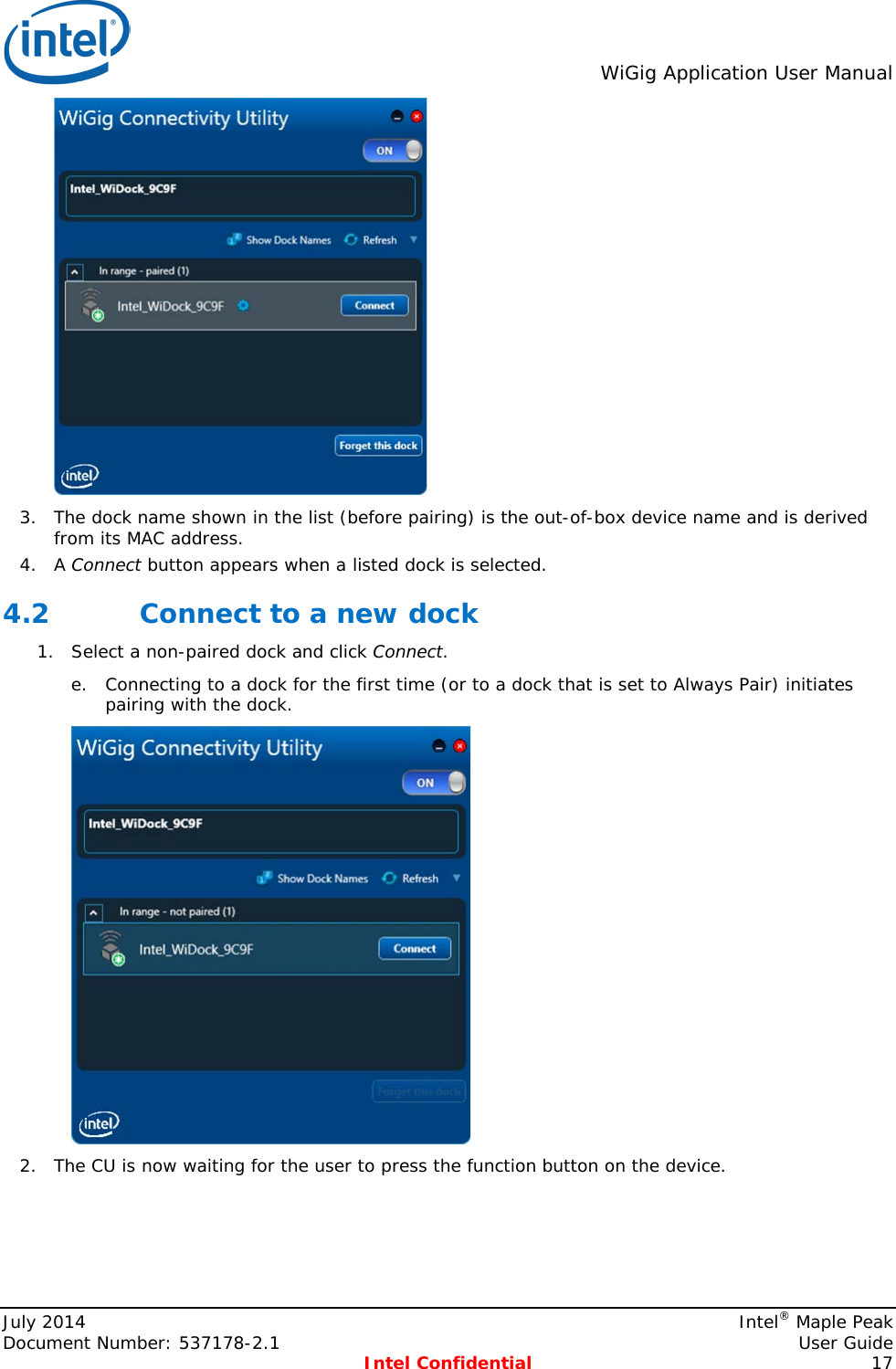
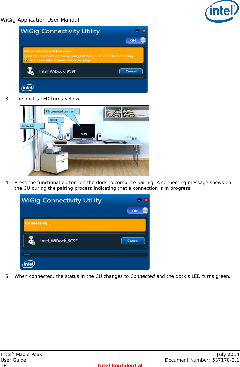
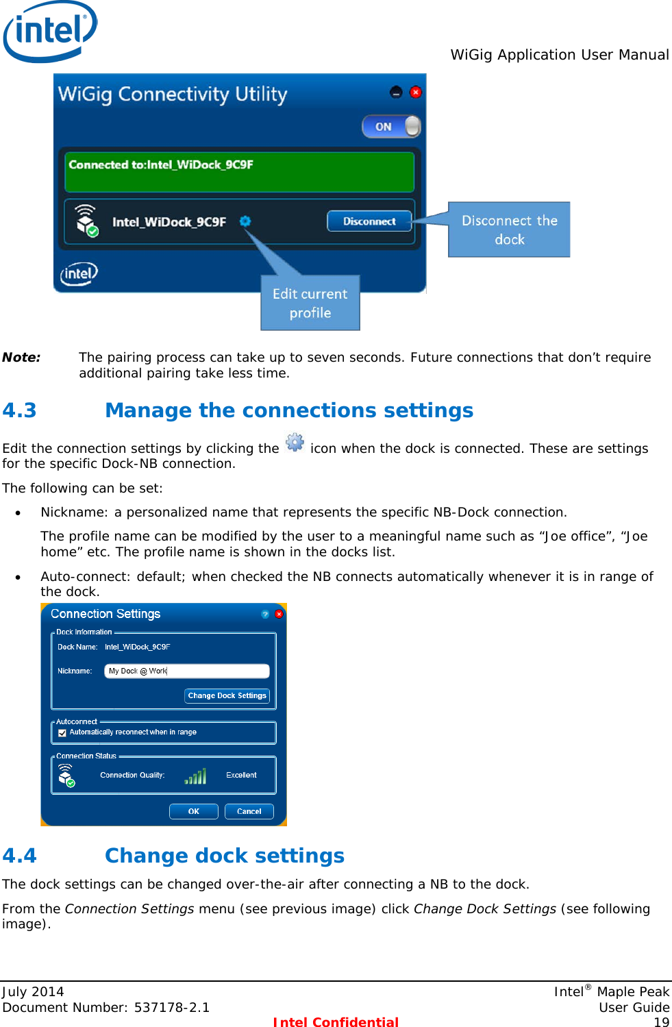
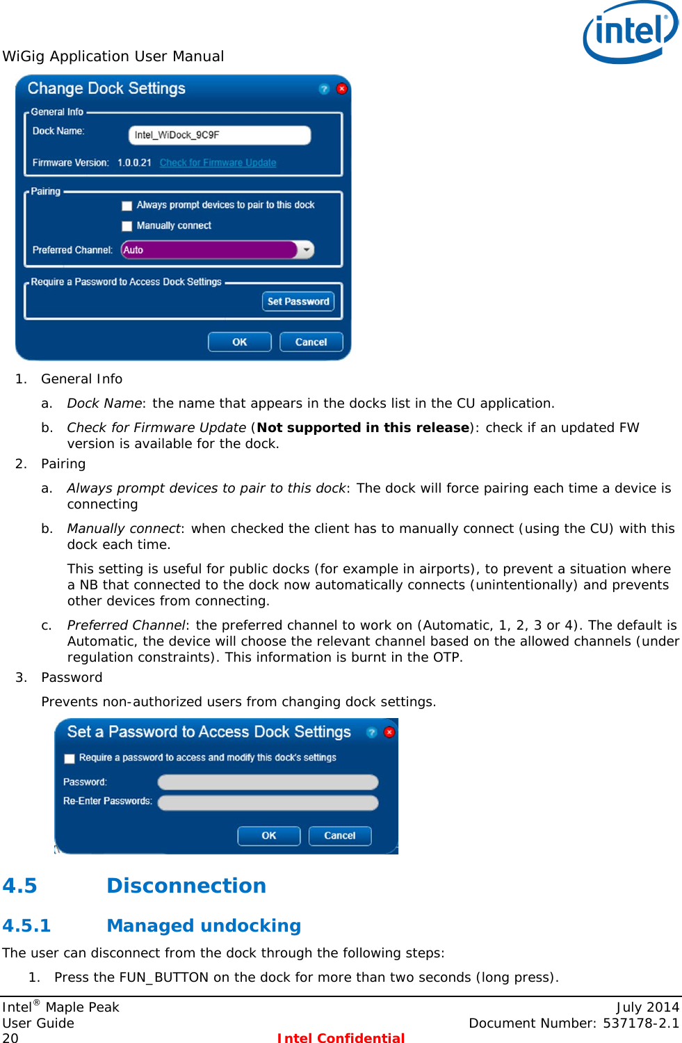
User Manual
Discussion / Help
Navigation