Intel 13110NG Wireless Network Adapter User Manual Intel WiGig VR User Guide draft3
Intel Mobile Communications Wireless Network Adapter Intel WiGig VR User Guide draft3
Intel >
User Manual

Document Number: 537178-3.11
Intel
®
Wireless Gigabit VR
User Guide
March 2018
Revision 1.0
Intel Confidential

Intel
®
Wireless Gigabit (Maple Peak)
User Guide March 2018
2 Intel Confidential Document Number: 537178-3.11
Notice: This document contains information on products in the design phase of development. The information here is subject to
change without notice. Do not finalize a design with this information.
INFORMATION IN THIS DOCUMENT IS PROVIDED IN CONNECTION WITH INTEL PRODUCTS. NO LICENSE, EXPRESS OR IMPLIED,
BY ESTOPPEL OR OTHERWISE, TO ANY INTELLECTUAL PROPERTY RIGHTS IS GRANTED BY THIS DOCUMENT. EXCEPT AS
PROVIDED IN INTEL’S TERMS AND CONDITIONS OF SALE FOR SUCH PRODUCTS, INTEL ASSUMES NO LIABILITY WHATSOEVER
AND INTEL DISCLAIMS ANY EXPRESS OR IMPLIED WARRANTY, RELATING TO SALE AND/OR USE OF INTEL PRODUCTS INCLUDING
LIABILITY OR WARRANTIES RELATING TO FITNESS FOR A PARTICULAR PURPOSE, MERCHANTABILITY, OR INFRINGEMENT OF ANY
PATENT, COPYRIGHT OR OTHER INTELLECTUAL PROPERTY RIGHT.
A "Mission Critical Application" is any application in which failure of the Intel Product could result, directly or indirectly, in personal
injury or death. SHOULD YOU PURCHASE OR USE INTEL’S PRODUCTS FOR ANY SUCH MISSION CRITICAL APPLICATION, YOU
SHALL INDEMNIFY AND HOLD INTEL AND ITS SUBSIDIARIES, SUBCONTRACTORS AND AFFILIATES, AND THE DIRECTORS,
OFFICERS, AND EMPLOYEES OF EACH, HARMLESS AGAINST ALL CLAIMS COSTS, DAMAGES, AND EXPENSES AND REASONABLE
ATTORNEYS' FEES ARISING OUT OF, DIRECTLY OR INDIRECTLY, ANY CLAIM OF PRODUCT LIABILITY, PERSONAL INJURY, OR
DEATH ARISING IN ANY WAY OUT OF SUCH MISSION CRITICAL APPLICATION, WHETHER OR NOT INTEL OR ITS SUBCONTRACTOR
WAS NEGLIGENT IN THE DESIGN, MANUFACTURE, OR WARNING OF THE INTEL PRODUCT OR ANY OF ITS PARTS.
Intel may make changes to specifications and product descriptions at any time, without notice. Designers must not rely on the
absence or characteristics of any features or instructions marked “reserved” or “undefined.” Intel reserves these for future
definition and shall have no responsibility whatsoever for conflicts or incompatibilities arising from future changes to them. The
information here is subject to change without notice. Do not finalize a design with this information.
Intel software products are copyrighted by and shall remain the property of Intel Corporation. Use, duplication, or disclosure is
subject to restrictions stated in Intel’s Software License Agreement, or in the case of software delivered to the government, in
accordance with the software license agreement as defined in FAR 52.227-7013.
The products described in this document may contain design defects or errors known as errata which may cause the product to
deviate from published specifications. Current characterized errata are available on request.
The code names presented in this document are only for use by Intel to identify products, technologies, or services in development
that have not been made commercially available to the public, i.e., announced, launched, or shipped. They are not "commercial"
names for products or services and are not intended to function as trademarks.
Contact your local Intel sales office or your distributor to obtain the latest specifications and before placing your product order.
Copies of documents which have an order number and are referenced in this document, or other Intel literature may be obtained by
calling 1-800-548-4725 or by visiting Intel’s website at http://www.intel.com/design/literature.htm.
Intel is a trademark of Intel Corporation or in the US and other countries.
* Other brands and names may be claimed as the property of others.
Copyright © 2018 Intel Corporation. All rights reserved.

Intel
®
Wireless Gigabit (Maple Peak)
March 2018 User Guide
Document Number: 537178-3.11 Intel Confidential 3
Contents
1Introduction ................................................................................................................. 7
1.1Scope ............................................................................................................... 7
1.2References......................................................................................................... 7
1.3Terminology ....................................................................................................... 7
1.4VR usage model ................................................................................................. 8
2HW Setup .................................................................................................................... 10
2.1WGA ................................................................................................................ 10
2.1.1WGA components .............................................................................. 10
The WGA system includes the following components (see Figure 2-1): ................................. 10
2.1.2WGA assembly .................................................................................. 10
1.Open the PC cover and insert the WGA to one of the free PCIe slots. Close the PC
cover. .............................................................................................................. 10
2.Connect the antenna box to the SMA connector on the external panel ....................... 10
3.Position the PC in a clear gaming area of up to 7x7m, without line-of-sight obstacles ... 10
4.Position the Antenna box at a height of 0.75-1.25m , directed towards center of the
room ............................................................................................................... 10
2.1.3PC Requirements ............................................................................... 11
2.1.4Platforms limitations…?? ..................................................................... 12
2.2HMDA .............................................................................................................. 12
2.2.1HMDA components ............................................................................ 12
The HMDA FW is burnt to flash by the OEM during production line process (See Ref 7 for more
details). The FW is updated with new versions over the air by the WGA. (see 4.3) ....... 12
3Software Install (WGA) .............................................................................................. 13
Intel WiGig software has two installation options: .............................................................. 13
3.1WiGig installation without Intel CU ....................................................................... 13
3.2WiGig installation with Intel CU ............................................................................ 14
3.2.1WiGig installation (with Intel CU) ......................................................... 14
3.2.2WiGig uninstall (with Intel CU) ............................................................ 15
3.3Flow for running VR ........................................................................................... 15
4WiGig Application User Manual ................................................................................... 16
4.1Launch the Intel
®
Wireless VR Dashboard .............................................................. 16
4.2CU functionalities ............................................................................................... 16
4.2.1First time connection ......................................................................... 16
4.2.2Automatic connections for existing profile ............................................. 19
4.2.3Disconnect from the HMDA ................................................................. 20
4.2.4WiGig Radio Off ................................................................................. 20
4.2.5HMDA settings .................................................................................. 21
When selecting the “Wireless Headset Settings” the window in Figure 3-12 pops up. .............. 22
4.2.6About information.............................................................................. 22
4.2.7Connection Quality Indication (CQI) ..................................................... 22
4.3HMDA FW Update .............................................................................................. 23
4.3.1FWU errors ....................................................................................... 24
4.4Notification messages in CU ................................................................................ 25
4.4.1Device status Errors ........................................................................... 25
4.4.2Device RF state Errors ........................................................................ 27
5LEDs and Buttons/GPIOs ............................................................................................ 29
5.1LEDs ................................................................................................................ 29
5.2Buttons/GPIOs .................................................................................................. 29
6WiGig events in Windows Event Viewer (TBD) ........................................................... 31

Intel
®
Wireless Gigabit (Maple Peak)VR
User Guide March 2018
4 Intel Confidential Document Number: 537178-3.11
6.1WiGig Event Properties ....................................................................................... 31
6.2WiGig Event Data .............................................................................................. 31
6.3Accessing WiGig Events Log ................................................................................ 31
7End User Logging Utility (EULU) ................................................................................. 33

Intel
®
Wireless Gigabit (Maple Peak)
March 2018 User Guide
Document Number: 537178-3.11 Intel Confidential 5
Figures
Figure 1-1WiGig VR usage model ...................................................................................... 9
Figure 2-1 – WGA components ................................................................................................ 10
Figure 2-2 - WGA setup 11
Figure 3-1 - End User License Agreement dialog box .................................................................. 14
Figure 3-2 - Success message ................................................................................................ 14
Figure 3-3 - Uninstall window ................................................................................................. 15
Figure 3-4 - SteamVR Ready .................................................................................................. 15
Figure 3-5 - SteamVR Not Ready ............................................................................................. 15
Figure 4-1 - OOB window ....................................................................................................... 16
Figure 4-2 - Intel® Wireless VR First Time Connection ............................................................... 17
Figure 4-3 - HMD connected message ...................................................................................... 17
Figure 4-4 – Scanning 18
Figure 4-5 - Connect New VR Headset ...................................................................................... 18
Figure 4-6 New connection timeout message ............................................................................ 19
Figure 4-7 - Scanning 19
Figure 4-8 - Wireless Radio Off ............................................................................................... 20
Figure 4-9 - Confirm Radio Off ................................................................................................ 20
Figure 4-10 - Radio Off status ................................................................................................. 21
Figure 4-11 - Wireless Radio On .............................................................................................. 21
Figure 4-12 - CU settings menu .............................................................................................. 21
Figure 4-13 - Wireless Headset Settings ................................................................................... 22
Figure 4-14 - ABout window ................................................................................................... 22
Figure 4-15 - Connection Quality Indication .............................................................................. 23
Figure 4-16 - HMDA SW Update progress ................................................................................. 23
Figure 4-17 - HMDA SW Update complete ................................................................................. 24
Figure 4-18 - SW Update Error during FWU process ................................................................... 24
Figure 4-19 - SW Update Error due to SW incompatibility ........................................................... 25
Figure 4-20 - Driver disabled error message ............................................................................. 25
Figure 4-21 - RFEM not connected error message ...................................................................... 26
Figure 4-22Antenna Setup instructions ............................................................................... 26
Tables
Table 1-1References ...................................................................................................... 7
Table 5-1CQI levels ...................................................................................................... 23
Table 5-2Error code cases – device status ....................................................................... 27
Table 5-3Error code cases – RF state error....................................................................... 27
Table 6-1 LEDs behavior ..................................................................................................... 29
Table 6-2Signals behavior ............................................................................................. 29
Table 7-1List of groups for Task Category parameter in WiGig Events .................................. 31

Intel
®
Wireless Gigabit (Maple Peak)VR
User Guide March 2018
6 Intel Confidential Document Number: 537178-3.11
Revision History
Revision Description Date
1.0 Initial release February, 2018

Introduction
Intel
®
Wireless Gigabit (Maple Peak)
March 2018 User Guide
Document Number: 537178-3.11 Intel Confidential 7
1 Introduction
1.1 Scope
This document is targeted for OEMs to get familiar with the Intel
®
WiGig VR solution components. It
provides flows for setup, installation and configuration. In case further troubleshooting is required
please refer to Ref 9.
1.2 References
Table 1-1 References
Document name Description
Ref 1
571416_Intel_WiGig-W11100_VR_PnP_EPS_Rev1.1 WGig VR PnP External Product Specifications
(EPS)
Ref 2
571415_Intel_WiGig_13110_VR_MpP_SNK_EPS_Rev
1.1 WiGig VR Maple Peak SNK External Product
Specifications (EPS)
Ref 3
557232_WiGig_R-
FEM_External_Product_Specification_Rev3.0 WiGig R-FEM2 External Product Specifications
(EPS)
Ref 4
563709_Intel_Wireless_Gigabit_Antenna_M10101R_
RFEM3_EPS_Rev0.7 WiGig R-FEM3 External Product Specifications
(EPS)
Ref 5
571610_Intel_WiGig-W11100_VR_PnP_PDG_Rev0_8 WiGig VR PnP Platform Design Guidelines
Ref 5
571636_Intel_WiGig_13110_VR_MpP_SNK_PDG_Rev
0_8 WiGig VR MpP SNK Platform Design Guidelines
Ref 6
572100_Intel_WiGig_VR_PTG_Rev1_0 Intel WiGig VR Platform Testing Guidelines
Ref 8
Intel_WiGig_SDK_API (part of the SW package) API for WiGig driver SDK
Ref 9
First Aid Debug Kit
1.3 Terminology
Acronym Description
VR-PnP Intel
®
Wireless Gigabit W11100 Pine Peak WiGig-only module. Includes WiGig MAC/BB chip
solution for VR-Client side.
VR-SNK Intel
®
Wireless Gigabit Sink-M 13110 VR WiGig-only module. Includes WiGig MAC/BB chip
solution for VR-SNK side.
R-FEM2 Intel
®
Wireless Gigabit Antenna-M 10042R
R-FEM3 Intel
®
Wireless Gigabit Antenna-M 10101R
LOS Line of sight
NLOS Non line of sight (single reflection)

Introduction
Intel
®
Wireless Gigabit (Maple Peak)
User Guide March 2018
8 Intel Confidential Document Number: 537178-3.11
Acronym Description
TPT Throughput
MA-USB Media agnostic USB – WiGig USB PAL
SNK Sink; receiver in A/V applications
HDMI High definition multimedia interface
SKU Stock keeping unit
VR Virtual reality
HMD Head-mounted display
HID Human interface device
GPU Graphics processing unit
IMU Inertial measurement unit
WGA-P WiGig gaming add-on
HMDA HMD add-on, refering to WiGig solution for VR HMD side
WGE WiGig gaming embedded, referring to the WiGig solution, embedded in VR PC laptops
1.4 VR usage model
The Virtual Reality (VR) tethered system is composed of a head-mounted display (HMD) that is cable-
connected to a PC or Laptop. In such system, HMD user is limited to specific movement-types and
distance due to the cable connection with the PC.
The VR-SNK product, together with the VR-PnP WiGig peer product (see Ref1 and Ref2), allows
wireless tethering of the VR system. By communicating all video, audio and control content over a
WiGig link, the HMD becomes a stand-alone component, providing freedom of movement and the best
user experience. WiGig video latencies and ultra-short USB latencies, combined with superior video
quality and low power consumption, allow for a wired-like gaming experience. A high-throughput USB
back-channel allows for connection of state-of-the-art human interface devices (HIDs), such as motion
detectors and HD cameras, without any quality degradation.
Figure 1-1 presents WiGig VR usage model setup. The components at each side are:
VR-PC-Platform side, which is a client-side WiGig system, based on VR-PnP and R-FEM2
products. See more details in Table 1-1 1.
VR-HMD side, connected to HMDA (HMD add on). HMDA is an SNK-side WiGig system, based
on VR-SNK and R-FEM3 products. See more details in Table 1-1 2.

Introduction
Intel
®
Wireless Gigabit (Maple Peak)
March 2018 User Guide
Document Number: 537178-3.11 Intel Confidential 9
Figure 1-1 WiGig VR usage model
VR‐PC‐Platform
(VR‐PnP&RFEM2)
VR‐HMDand
HMDA(VR‐SNK&RFEM3x2)
WiGigLink
HW Setup
Intel
®
Wireless Gigabit (Maple Peak)
User Guide March 2018
10 Intel Confidential Document Number: 537178-3.11
2 HW Setup
2.1 WGA
WGA is WIGig Gaming add-on, installed on the PC side. WiGig application is installed on the PC to
control the connection with the HMDA side. See 3 for more details.
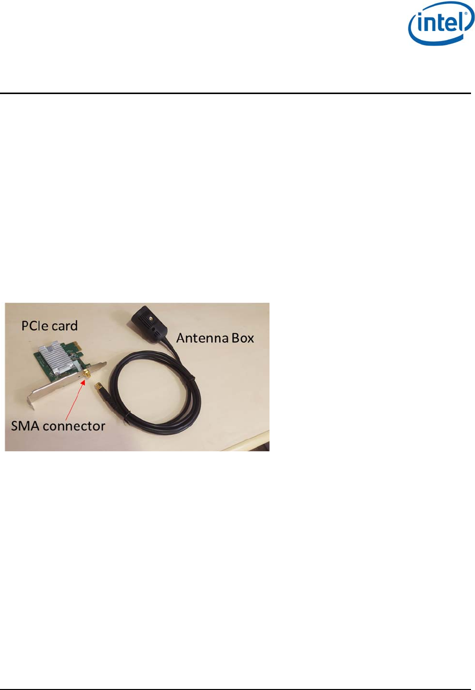
2.1.1 WGA components
The WGA system includes the following components (see Figure 2-1):
VR PC desktop platform – a VR-compatible platform
PCIe card (with PnP module soldered-down)
Antenna box – a standalone box connected over a ~2m coax cable to an SMA connector
exposed by PCIe-WGA’s external panel
Figure 2-1 – WGA components
2.1.2 WGA assembly
1. Open the PC cover and insert the WGA to one of the free PCIe slots. Close the PC cover.
2. Connect the antenna box to the SMA connector on the external panel
3. Position the PC in a clear gaming area of up to 7x7m, without line-of-sight obstacles
4. Position the Antenna box at a height of 0.75-1.25m , directed towards center of the room
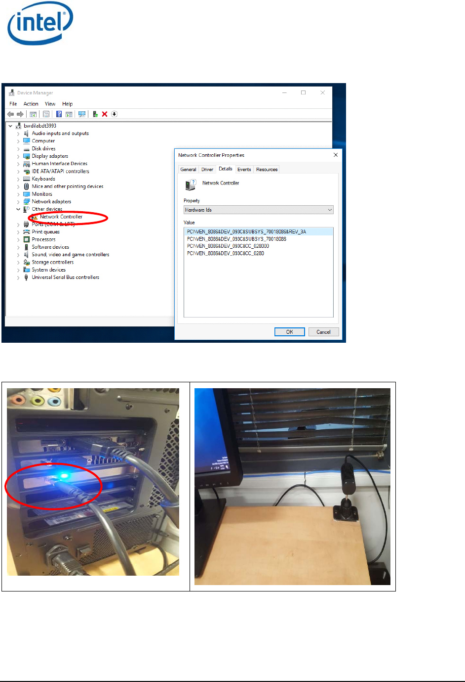
5. You can check the device manager for “Network Controller” with the Hardware ID as in Figure
2-2, to make sure card is inserted correctly. (Note that after SW installation you should see
WiGig driver, see Figure 3-1)
HW Setup
Intel
®
Wireless Gigabit (Maple Peak)
March 2018 User Guide
Document Number: 537178-3.11 Intel Confidential 11
Figure 2-2 - Device manager - PCIe card device
Figure 2-3 - WGA setup – SMA connector, Antenna box mounted on table
2.1.3 PC Requirements
In order to run VR content smoothly there is minimum system requirements as below:

HW Setup
Intel
®
Wireless Gigabit (Maple Peak)
User Guide March 2018
12 Intel Confidential Document Number: 537178-3.11
– CPU –
– GPU –
– OS – Win 7 or Win10 64bit..
2.1.4 Platforms limitations…??
AMD – only on PCH..
….
…
2.2 HMDA
The HMDA is a wireless HMD adapter, integrated on the HMD by the OEM, that allows untethering the
HMD from the PC.
2.2.1 HMDA components
MpL-SNK VR module
2 x RFEM3 modules connected over coax cable to MpL-SNK
The HMDA FW is burnt to flash by the OEM during production line process (See Ref 7 for more details).
The FW is updated with new versions over the air by the WGA. (see 4.3)
Software Install (WGA)
Intel
®
Wireless Gigabit (Maple Peak)
March 2018 User Guide
Document Number: 537178-3.11 Intel Confidential 13
3 Software Install (WGA)
The SW package should be provided by the OEM for installation on the PC side (WGA). This package
includes OEM drivers, WiGig driver and encoder driver . The PCIe card must be installed (see 2.1.2)
before the SW installation, otherwise WiGig driver installation will fail.
Intel WiGig software has two installation options:
Installer that includes Intel CU (Connection Utility) application
Installer that installs only WiGig driver without Intel CU. For this option the OEM needs to
develop its proprietary application which is integrated to WiGig SDK API
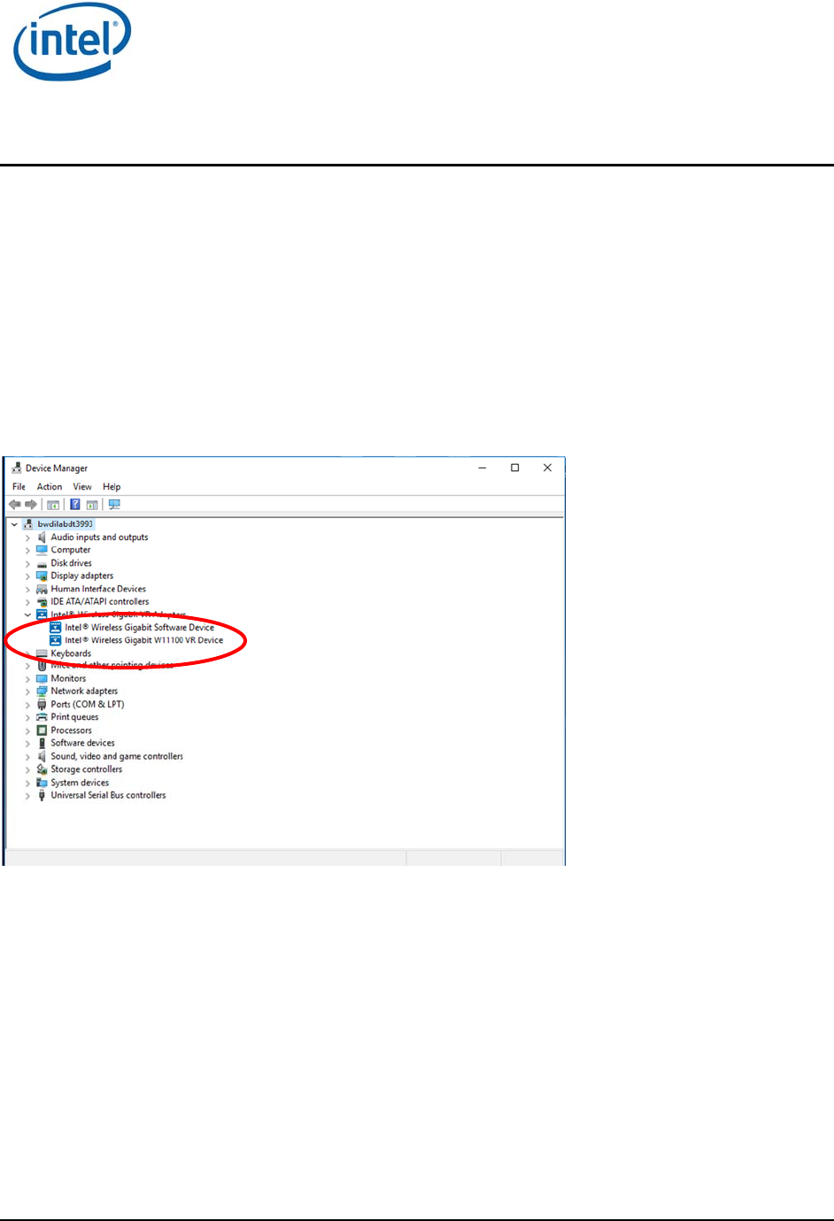
After installation check the Device Manager for “Intel Wireless Gigabit VR Adapters” as in Figure 3-1.
Figure 3-1 - WiGig driver in Device Manager
3.1 WiGig installation without Intel CU
If the OEM choose to develop their own CU application it requires an integration with Intel SDK (see
Ref 8 for more details). OEM package for the end user should include OEM CU and Intel WiGig driver.
WiGig driver should be installed by (OEM) calling to setup.exe from NOCU_VR layout\Win7Plus\.
For silent installation the following command should be used:
“SetUp.exe -silent -norestart -l C:\WiGig\InstallationLogs\WiGig_VR_NB_Setup_exe.txt”
For silent uninstall the following command should be used:
“SetUp.exe -silent -uninstall -norestart -l C:\WiGig\InstallationLogs\WiGig_VR_NB_Setup_exe.txt”
*Note that all CU features and user manual under 4 are related to Intel CU only and does not apply to
OEM CU. Please refer to the OEM for guidelines on their CU.

Software Install (WGA)
Intel
®
Wireless Gigabit (Maple Peak)
User Guide March 2018
14 Intel Confidential Document Number: 537178-3.11
3.2 WiGig installation with Intel CU
3.2.1 WiGig installation (with Intel CU)
1. Go to G_VR Layout\Win7Plus\ and run Setup.exe.
Figure 3-2 - End User License Agreement dialog box
2. Check the “I have reviewed and agree to the EULA” box, and click Install. This will install the
operational WiGig software for the WGA side.
3. When the application is successfully installed, Click Finish, see Figure 3-3.
Figure 3-3 - Success message
4. After installation you will be able to launch the Intel
®
Wireless VR Dashboard application from the
desktop shortcut or by searching the PC programs.

Software Install (WGA)
Intel
®
Wireless Gigabit (Maple Peak)
March 2018 User Guide
Document Number: 537178-3.11 Intel Confidential 15
3.2.2 WiGig uninstall (with Intel CU)
When uninstalling the Intel CU the user can select whether to keep the previous settings or discard
them, i.e. HMDA profile and settings (see more details about profiles in 4.2.2 and about HMDA
settings in 4.2.5)
Figure 3-4 - Uninstall window
3.3 Flow for running VR
Install SteamVR (please refer to SteamVR website)
Install OEM package as described above
Create a WiGig connection – see in 4.2.1 for WiGig connection creation through Intel CU
Open SteamVR – It should recognize the HMD and show Figure 3-5
Figure 3-5 - SteamVR Ready
If SteamVR is opened prior to the WiGig connection the HMD will not be detected and
Figure 3-6 will be shown.
Figure 3-6 - SteamVR Not Ready
WiGig Application User Manual
Intel
®
Wireless Gigabit (Maple Peak)
User Guide March 2018
16 Intel Confidential Document Number: 537178-3.11
4 WiGig Application User Manual
Note that this Chapter is only relevant if the SW was installed including Intel CU, as described in
paragraph 2.2. OEM CU will have different GUI and may or may not have similar functionalities. Please
refer to the OEM for instructions on its proprietary application.
4.1 Launch the Intel
®
Wireless VR Dashboard
To invoke the Intel
®
Wireless VR dashboard, double-click the icon on the desktop, or search for
this application under the PC programs.
4.2 CU functionalities
The Intel
®
Wireless VR is a dedicated application that runs on the PC (WGA side) and allows the user
to find, connect to, and configure an HMDA.
The CU application has a menu, status bar for a general WiGig status and a notification bar for more
information on the status. (See examples in below figures)
LEDs on the HMDA device provide additional feedback about the HMDA status.
The Function button on the HMDA device is used for controlling flows such as pairing and power down
indication. A recovery button is used to restore factory FW in case of an issue in current running FW.
(See 5 for more details on LEDs and Buttons)
4.2.1 First time connection
Every time that the WGA is connected to the HMDA, the CU application saves the HMDA profile to be
able to connect to it automatically in the following connections (see more details in 4.2.2). When
connecting to an HMDA for the first time, a pairing process will be initiated during connection.
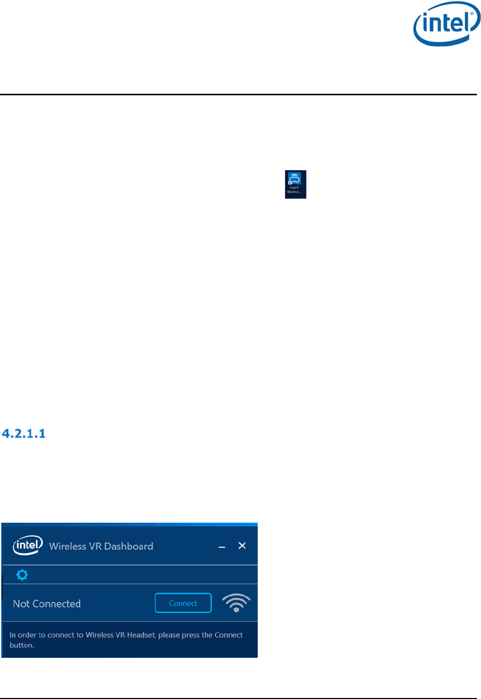
Out-of-Box / No Profile flows
When the CU is launched for the first time, or when no profile is saved in the CU, the connection flow
will be as follows:
1. Power on HMDA, verify functional LED is ON, displaying slow blinking green light (1 blinks/sec).
2. The CU will show “Not Connected” status and a “Connect” button, as can be seen in Figure 3-2.
Figure 4-1 - OOB window
WiGig Application User Manual
Intel
®
Wireless Gigabit (Maple Peak)
March 2018 User Guide
Document Number: 537178-3.11 Intel Confidential 17
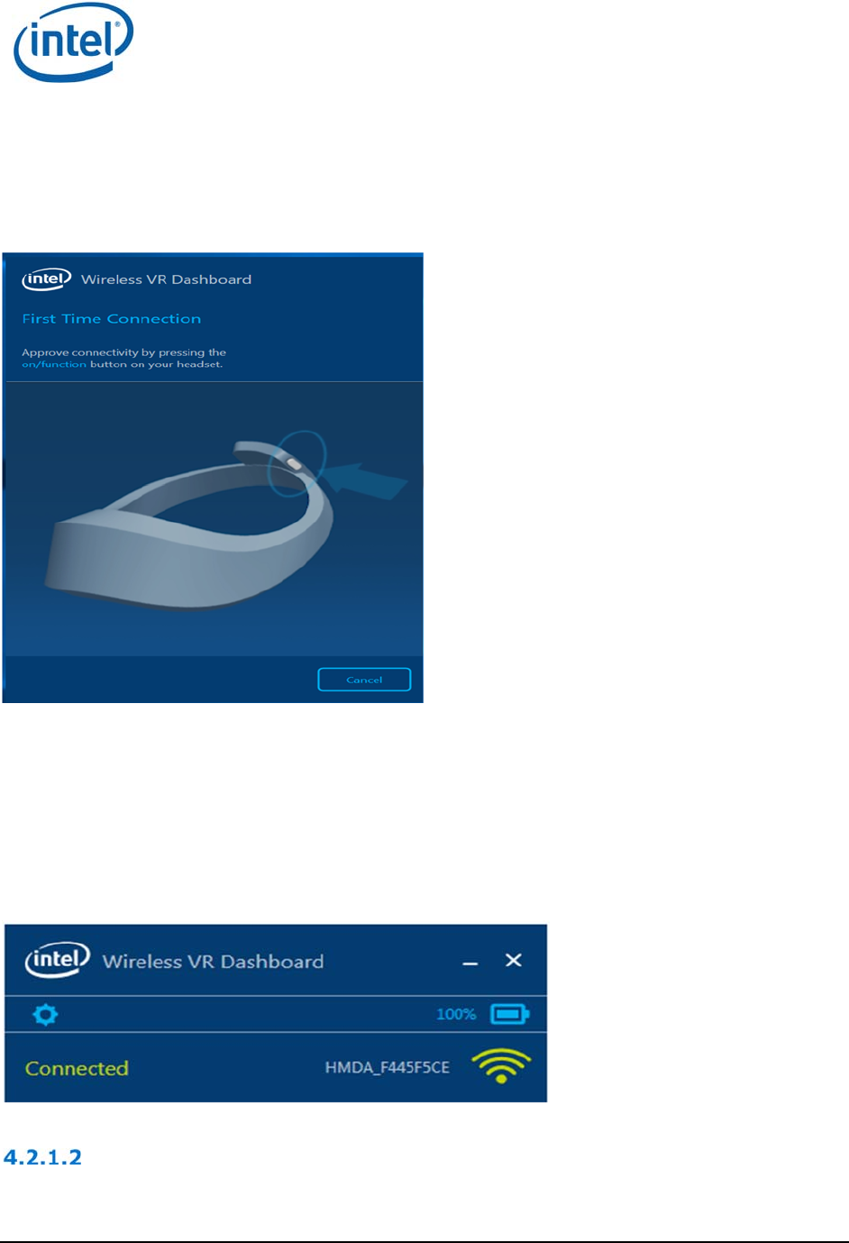
3. Press “Connect” in order to connect to an HMDA in the PC range (as written in the notification
bar). A pairing is required since no HMDA profile is saved on the WGA side. The following screen
will pop-up, see figure 3-4.
Figure 4-2 - Intel® Wireless VR First Time Connection
4. The HMDA LED will be fast blinking green light. Press your HMDA function button to confirm the
connection.
5. Note that all HMDAs in range may blink, but only the one that its button is pressed will be
connected.
6. After a successful pairing the status in the CU will be changed to Connected as in Error!
Reference source not found. and the HMDA LED will become constant green.
Figure 4-3 - HMD connected message
Congratulations! You’ve made your first wireless VR connection.
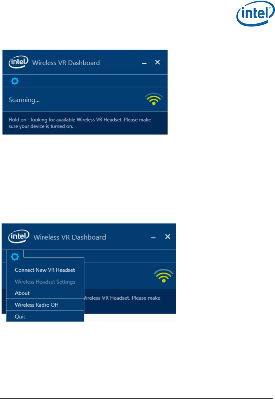
Add New Device
If the CU has a saved HMDA profile it will search for it and the CU will show “Scanning” as in Figure
4-4
WiGig Application User Manual
Intel
®
Wireless Gigabit (Maple Peak)
User Guide March 2018
18 Intel Confidential Document Number: 537178-3.11
Figure 4-4 – Scanning
In case the saved HMDA is not in range, or if the user wants to connect to another HMDA, the user
should press the Gear icon and select “Connect New VR Headset” (See Error! Reference source not
found.). Since only one HMDA profile is saved in the WGA, this operation will delete the saved profile
and search for HMDAs in range.
Similarly, if an HMDA is already connected and the user wishes to connect to another HMDA, he/she
should press the Gear icon and select “Connect New VR headset”. This will disconnect the current
HMDA and will start a connection process. The process will proceed as described in 16 similar to first
time connection.
Note that the profile of the disconnected HMDA will be deleted and a new pairing will be required on
next connection.
Figure 4-5 - Connect New VR Headset
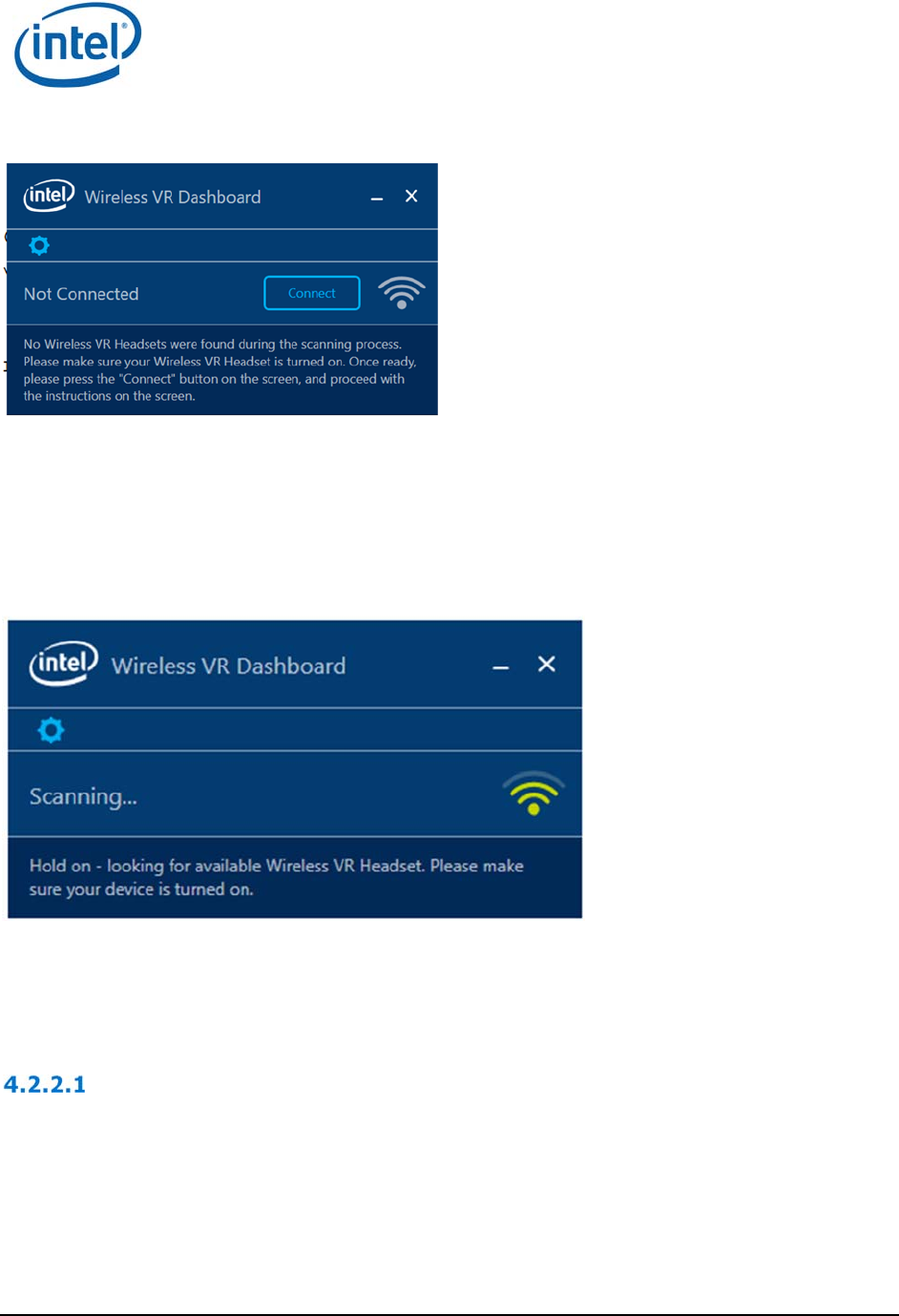
4.2.1.2.1 Add new device timeout
If there is no HMDA in range, or no one pressed the HMDA button to connect, within a predefined time
(currently defined as 2 minutes), the connection attempt will stop, the CU status will be set to “Not
connected” and the text as seen in Figure 4-6 will be in the notification bar.
WiGig Application User Manual
Intel
®
Wireless Gigabit (Maple Peak)
March 2018 User Guide
Document Number: 537178-3.11 Intel Confidential 19
Figure 4-6 New connection timeout message
4.2.2 Automatic connections for existing profile
After first connection of the WGA with an HMDA, a profile will be created for this specific HMDA and
the next time the CU is opened it will search for this specific HMDA and will connect to it automatically.
When launching the CU with a saved HMDA the following screen will be seen:
Figure 4-7 - Scanning
If the saved HMDA is in range it will connect to it automatically. This automatic connection will occur
either when opening the CU (and HMDA is in range) or when the HMDA is entering the range of the
WGA (and CU is open).
Automatic connection in Sx
When the WGA enters Sx power state while connected to the HMDA, the WiGig will be disconnected
and no video will be seen. When the WGA gets back to S0 mode the connection between HMDA and
WGA is restored automatically.
WiGig Application User Manual
Intel
®
Wireless Gigabit (Maple Peak)
User Guide March 2018
20 Intel Confidential Document Number: 537178-3.11
4.2.3 Disconnect from the HMDA
There is no specific command that disconnect the HMDA from the WGA but there are several ways to
achieve disconnection:
1. Taking the HMDA out of range of the WGA will eventually cause a link loss and a disconnection.
Getting in range again will auto-connect the HMDA, unless the profile was deleted.
2. Power off the HMDA will cause a WiGig disconnection
3. Closing the CU will disconnect the WiGig connection
4. “Add new device” menu will disconnect the current connection (in order to start a new connection)
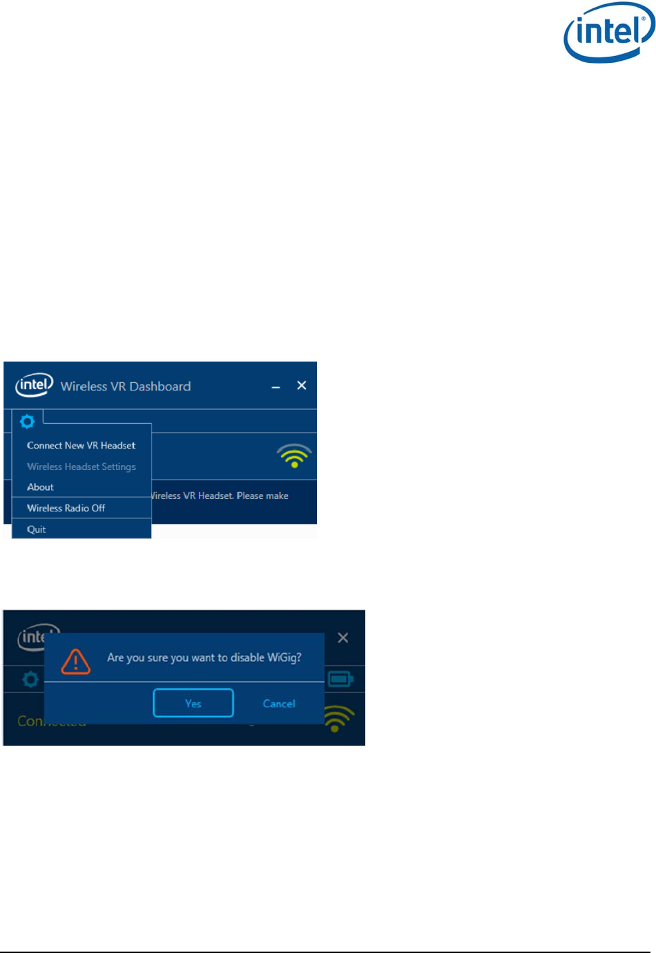
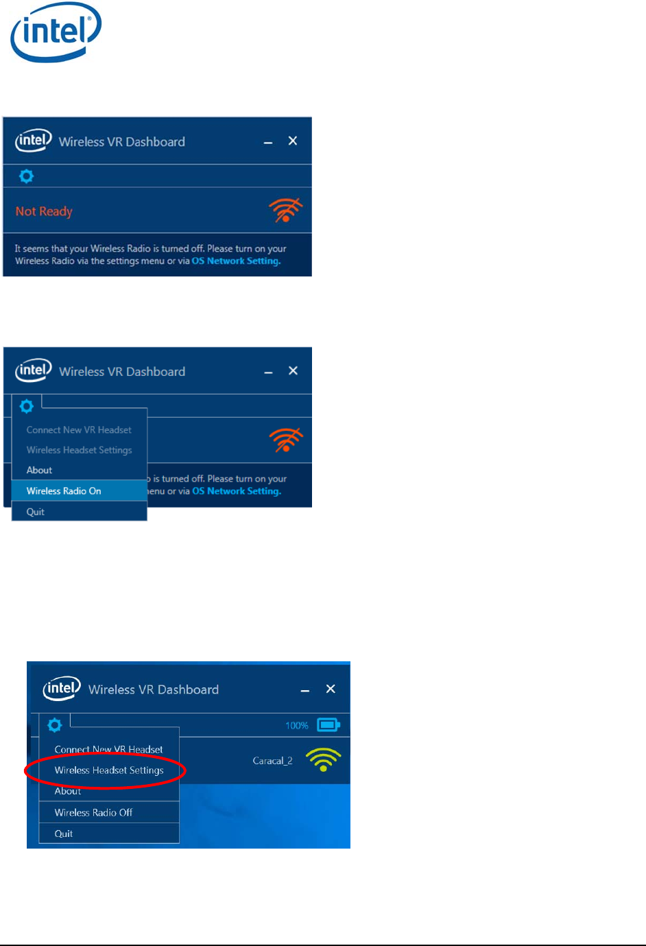
4.2.4 WiGig Radio Off
1. To turn the WiGig radio Off click on the Gear icon and select “Wireless Radio Off”.
Figure 4-8 - Wireless Radio Off
2. When the popup-menu in Error! Reference source not found. appears select yes.
Figure 4-9 - Confirm Radio Off
3. When WiGig Radio is Off, you cannot find and connect to a wireless HMDAs; The CU shows “Not
ready” as in Figure 4-10Error! Reference source not found.. Turn WiGig radio Off minimizes
the power consumption of the WiGig radio in the WGA side.
WiGig Application User Manual
Intel
®
Wireless Gigabit (Maple Peak)
March 2018 User Guide
Document Number: 537178-3.11 Intel Confidential 21
Figure 4-10 - Radio Off status
4. When the radio is off, the menu in the Gear icon will be changed as in Figure 4-11
Figure 4-11 - Wireless Radio On
5. Press “Wireless Radio On” to Turn the radio On again.
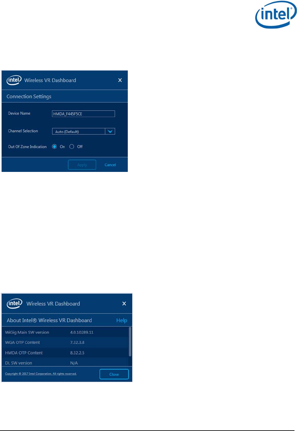
4.2.5 HMDA settings
While the WGA is connected to an HMDA you can configure the HMDA with few settings through
the CU. Click the Gear icon and select “Wireless Headset Settings”, see Error! Reference source
not found.Error! Reference source not found..
Figure 4-12 - CU settings menu
WiGig Application User Manual
Intel
®
Wireless Gigabit (Maple Peak)
User Guide March 2018
22 Intel Confidential Document Number: 537178-3.11
When selecting the “Wireless Headset Settings” the window in Error! Reference source not found.
pops up.
Figure 4-13 - Wireless Headset Settings
Device name – Set the name of the HMDA. This is the name that is seen in the CU when this
HMDA is connected. The name will be seen for this HMDA for connection with any WGA.
Channel Selection – default option is Auto – Allows WiGig driver to decide on the channel to
use after connecting to the WGA. Other options are Channel 1, Channel 2 or Channel 3 – this
option set a fixed channel for this connection. It is helpful when working in dense environment
to allow work on different channels for adjacent setups.
Out Of Zone Indication – In extreme conditions, when the video quality is bad for a certain
time, the HMD will show a bluish screen instead of the bad video. This feature can be disabled
or enabled using this radio button in the HMDA settings.
4.2.6 About information
A general information such as WiGig and DL SW version can be seen under the Gear icon “About”
menu. See Error! Reference source not found..
Figure 4-14 - ABout window
The Help link in the ‘About’ page is directed to WiGig page under Intel Customer Support website.
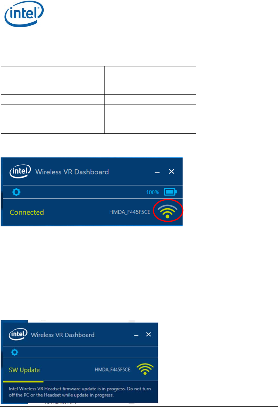
4.2.7 Connection Quality Indication (CQI)
When the PC and HMDA are connected there is an indication of the Channel Quality in the CU (red
circle in Error! Reference source not found..
WiGig Application User Manual
Intel
®
Wireless Gigabit (Maple Peak)
March 2018 User Guide
Document Number: 537178-3.11 Intel Confidential 23
There are 5 levels of the connection quality that are represented by 4 bars as defined in the below
table.
Table 4-1 CQI levels
Connection Quality Indication
(# of Bars) High-level Interpretation
4 Best
3 Good
2 Average
1 Poor
0 Insufficient
Figure 4-15 - Connection Quality Indication
4.3 HMDA FW Update
HMDA (VR-SNK) flash memory has 2 slots:
Factory slot – In the production line the FW is burnt to this slot.
Current slot – when upgrading the SW Over-The-Air (OTA) it is burnt to the current slot.
During connection process of the WGA and HMDA, if the SW versions of the WGA and HMDA are not
identical, the version at the WGA side will be burnt to the HMDA side OTA, which will cause either
upgrade or downgrade of the HMDA SW.
Figure 4-16 - HMDA SW Update progress
WiGig Application User Manual
Intel
®
Wireless Gigabit (Maple Peak)
User Guide March 2018
24 Intel Confidential Document Number: 537178-3.11
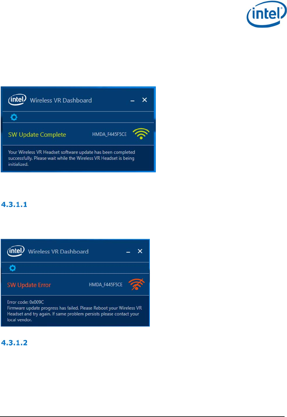
During the software update process the HMDA LED will be fast blinking Red.
Once the update process is complete, the HMDA SW is reset, and when reset complete, the WGA will
automatically re-connect
Figure 4-17 - HMDA SW Update complete
4.3.1 FWU errors
SW update progress error
In case of an error that occurred during the SW update process the Error in Error! Reference source
not found. will be seen in the CU status bar:
Figure 4-18 - SW Update Error during FWU process
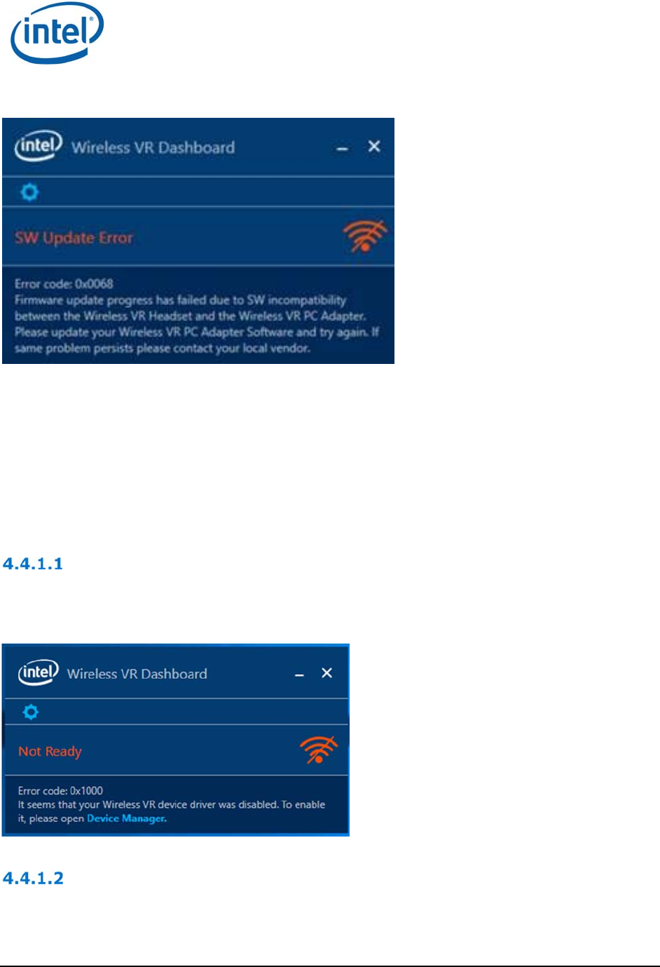
SW incompatibility error
In some cases there is incompatibility between the SW in the WGA and HMDA which does not allow a
FWU. In such case the Error in Error! Reference source not found. will be shown and the user
will have to install a different SW on the WGA side.
WiGig Application User Manual
Intel
®
Wireless Gigabit (Maple Peak)
March 2018 User Guide
Document Number: 537178-3.11 Intel Confidential 25
Figure 4-19 - SW Update Error due to SW incompatibility
4.4 Notification messages in CU
In cases of errors or possible limitations, the status bar in the CU (bottom of the CU window) will show
a text describing the error and a potential workaround.
See some examples below and a full list in Table 4-2 and Table 4-3
4.4.1 Device status Errors
Driver Disabled
When the WiGig driver is disabled, the below Error will be seen. In order to fix this issue the driver
should be enabled and a link to the Device Manager is provided.
Figure 4-20 - Driver disabled error message
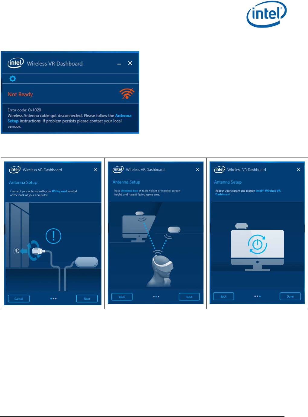
RFEM not connected
When the RFEM of the WGA is not connected (e.g. the user unplugged the antenna) the below error
message will be seen. Instructions for Antenna Setup (see figures below) are provided to help the user
fix the problem.
WiGig Application User Manual
Intel
®
Wireless Gigabit (Maple Peak)
User Guide March 2018
26 Intel Confidential Document Number: 537178-3.11
Figure 4-21 - RFEM not connected error message
Figure 4-22 Antenna Setup instructions

WiGig Application User Manual
Intel
®
Wireless Gigabit (Maple Peak)
March 2018 User Guide
Document Number: 537178-3.11 Intel Confidential 27
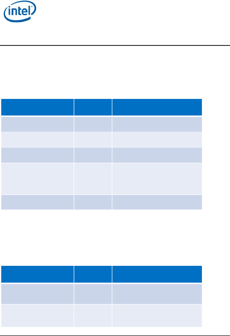
Table 4-2 Error code cases – device status
Item Error
Code Description Notification Text
1 0x1000 Device driver is disabled Error code: 0x1000
It seems that your Wireless VR device
driver was disabled. To enable it, please
open Device Manager
2 0x1014 RFEM Gen Malfunction Error code: 0x1014
Wireless Antenna cable got
disconnected. Please follow the Antenna
Setup instructions. If problem persists
please contact your local vendor
3 0x1020 RFEM not connected Error code: 0x1020
Wireless Antenna cable got
disconnected. Please follow the Antenna
Setup instructions. If problem persists
please contact your local vendor.
4 0x1022 HW not detected Error code: 0x1022
It seems that your Wireless VR Adapter
is not properly connected to PCI
interface. Please ensure that device is
connected to PCI interface and try
rebooting your computer.
If problem persists please contact your
local vendor.
5 0x1100 Generic Error Error code: 0x1100
It seems that your Wireless connection
experienced an unexpected error, please
wait few minutes while we try to restore
connection.
If problem persist, please reboot your
PC and your Wireless VR Headset. For
further assistance please visit Help at
intel.com
4.4.2 Device RF state Errors
Table 4-3 Error code cases – RF state error
Item Error Description Notification Text
1 Airplane Mode is enabled WiGig has been disabled by Airplane Mode. You
must enable Intel WiGig to find and connect to

WiGig Application User Manual
Intel
®
Wireless Gigabit (Maple Peak)
User Guide March 2018
28 Intel Confidential Document Number: 537178-3.11
Wireless Headsets. To enable WiGig, turn
Airplane Mode off.
2 RF Off due to Critical Temperature Please wait few minute and reboot your Wireless
VR Headset (should be changed)
3 WiGig disabled due to physical switch WiGig has been disabled by a physical switch on
your computer. You must enable Intel WiGig to
find and connect to wireless Headsets. To enable
WiGig, turn the physical switch back on.
4 WiGig disabled by SW It seems that your Wireless Radio is turned off.
Please turn on your Wireless Radio via the
settings menu or via OS Network Setting.
LEDs and Buttons/GPIOs
Intel
®
Wireless Gigabit (Maple Peak)
March 2018 User Guide
Document Number: 537178-3.11 Intel Confidential 29
5 LEDs and Buttons/GPIOs
WiGig VR-SNK provides two LED signals: Red and Green for status indication for the user. It also
provides Two GPIO Input signals that allow the user to control the WiGig flows. OEM is responsible to
implement the final UX based on these LEDs and signals. See REF 2 for more details.
5.1 LEDs
The following table provides details on the different states and LEDs behavior.
Table 5-1 LEDs behavior
System State LED Behavior
Discovery Green Slow Blink (1 blink/second)
Waiting PBC Green Fast Blink (4 blinks/second)
Connected Green Constant On
Errors:
CT-Kill
FW Upgrade Error
Red Constant On
FW Upgrade Red Fast Blink (4 Hz)
5.2 Buttons/GPIOs
There are 2 Input GPIO signals for the HMDA – Function signal and Recovery signal.
It is the OEM responsibility to define the UX for the buttons controlling these signals. The signals
behavior is defined as below:
Table 5-2 Signals behavior
Signal Pulse Behavior
Function GPIO Short When in “Wait for PBC” state, it will
trigger connection establishment
Function GPIO Long Power Down Indication – provides an
indication that WiGig will be powered
down within X secs. This allows the

LEDs and Buttons/GPIOs
Intel
®
Wireless Gigabit (Maple Peak)
User Guide March 2018
30 Intel Confidential Document Number: 537178-3.11
WiGig driver to complete all flows
and have a safe power down.
Recovery GPIO ~2 secs high
pulse during
power cycle
HMDA FW is restored to factory slot,
profile and HMDA settings are
deleted
There is an additional GPIO which is defined as Output and allows the WiGig driver to indicate it is not
connected. This allows OEM to implement HMDA power save.
For more details on all signals please see REF 2.

WiGig events in Windows Event Viewer (TBD for WiGig VR)
Intel
®
Wireless Gigabit (Maple Peak)
March 2018 User Guide
Document Number: 537178-3.11 Intel Confidential 31
6 WiGig events in Windows Event
Viewer (TBD for WiGig VR)
WiGig SW provides logging information to Windows Event Viewer, both for local PC and for the
connected WiGig HMDA. This information appears in Windows Event Viewer under Applications and
Services Logs -> Intel® WiGig.
6.1 WiGig Event Properties
The events are distinguished by the following list of properties:
Log Name: Intel® WiGiG
Level: can be
o Information – Events with this level provides informative data of WiGig flow.
o Error - Event with this level provides data for erroneous WiGig flow.
Source: can be
o iWiGig-Local – Events logged from local WGA side
o iWiGig-Remote – Events logged from remote HMDA side, that is, WiGig connected to
the WGA
Event ID: Will be always 256
Task Category: The index for this parameter may belong to the groups listed in Table 6-1. TBD
Table 6-1 List of groups for Task Category parameter in WiGig Events
Task Category index range Group type
1 0-199 TBD
2 200-299 TBD
3 300-399 TBD
4 600-699 TBD
6.2 WiGig Event Data
The data per each event provides the following information:
TBD.
6.3 Accessing WiGig Events Log
The steps to access the WiGig Events log are
1. Open the Windows Event Viewer.
2. On the left-hand pane, Go to Applications and Services Logs->Intel® WiGig.
The middle pane displays the list of WiGig events.
3. The user can click on each event and see its specific details on the bottom pane.

WiGig events in Windows Event Viewer (TBD for WiGig VR)
Intel
®
Wireless Gigabit (Maple Peak)
User Guide March 2018
32 Intel Confidential Document Number: 537178-3.11
4. By right-clicking on Applications and Services Logs->Intel® WiGig (on the left-hand pane),
user may save the WiGig Events log or perform other operations as allowed by the Event
Viewer.

End User Logging Utility (EULU)
Intel
®
Wireless Gigabit (Maple Peak)
March 2018 User Guide
Document Number: 537178-3.11 Intel Confidential 33
7 End User Logging Utility (EULU)