Intel 18260NG Wireless Network Adapter User Manual 537178 WiGig User Guide Rev3 3
Intel Mobile Communications Wireless Network Adapter 537178 WiGig User Guide Rev3 3
Intel >
Contents
- 1. User Manual
- 2. User Manaul
- 3. Users Manual
User Manaul

Document Number: 537178-3.3
Intel
®
Wireless Gigabit v2.0
User Guide
October 2015
Revision 3.3
Intel Confidential

Intel
®
Wireless Gigabit v2.0
User Guide October 2015
2 Intel Confidential Document Number: 537178-3.3
Notice: This document contains information on products in the design phase of development. The information here is subject to
change without notice. Do not finalize a design with this information.
INFORMATION IN THIS DOCUMENT IS PROVIDED IN CONNECTION WITH INTEL PRODUCTS. NO LICENSE, EXPRESS OR IMPLIED,
BY ESTOPPEL OR OTHERWISE, TO ANY INTELLECTUAL PROPERTY RIGHTS IS GRANTED BY THIS DOCUMENT. EXCEPT AS
PROVIDED IN INTEL’S TERMS AND CONDITIONS OF SALE FOR SUCH PRODUCTS, INTEL ASSUMES NO LIABILITY WHATSOEVER
AND INTEL DISCLAIMS ANY EXPRESS OR IMPLIED WARRANTY, RELATING TO SALE AND/OR USE OF INTEL PRODUCTS INCLUDING
LIABILITY OR WARRANTIES RELATING TO FITNESS FOR A PARTICULAR PURPOSE, MERCHANTABILITY, OR INFRINGEMENT OF ANY
PATENT, COPYRIGHT OR OTHER INTELLECTUAL PROPERTY RIGHT.
A "Mission Critical Application" is any application in which failure of the Intel Product could result, directly or indirectly, in personal
injury or death. SHOULD YOU PURCHASE OR USE INTEL’S PRODUCTS FOR ANY SUCH MISSION CRITICAL APPLICATION, YOU
SHALL INDEMNIFY AND HOLD INTEL AND ITS SUBSIDIARIES, SUBCONTRACTORS AND AFFILIATES, AND THE DIRECTORS,
OFFICERS, AND EMPLOYEES OF EACH, HARMLESS AGAINST ALL CLAIMS COSTS, DAMAGES, AND EXPENSES AND REASONABLE
ATTORNEYS' FEES ARISING OUT OF, DIRECTLY OR INDIRECTLY, ANY CLAIM OF PRODUCT LIABILITY, PERSONAL INJURY, OR
DEATH ARISING IN ANY WAY OUT OF SUCH MISSION CRITICAL APPLICATION, WHETHER OR NOT INTEL OR ITS SUBCONTRACTOR
WAS NEGLIGENT IN THE DESIGN, MANUFACTURE, OR WARNING OF THE INTEL PRODUCT OR ANY OF ITS PARTS.
Intel may make changes to specifications and product descriptions at any time, without notice. Designers must not rely on the
absence or characteristics of any features or instructions marked “reserved” or “undefined.” Intel reserves these for future
definition and shall have no responsibility whatsoever for conflicts or incompatibilities arising from future changes to them. The
information here is subject to change without notice. Do not finalize a design with this information.
Intel software products are copyrighted by and shall remain the property of Intel Corporation. Use, duplication, or disclosure is
subject to restrictions stated in Intel’s Software License Agreement, or in the case of software delivered to the government, in
accordance with the software license agreement as defined in FAR 52.227-7013.
The products described in this document may contain design defects or errors known as errata which may cause the product to
deviate from published specifications. Current characterized errata are available on request.
The code names presented in this document are only for use by Intel to identify products, technologies, or services in development
that have not been made commercially available to the public, i.e., announced, launched, or shipped. They are not "commercial"
names for products or services and are not intended to function as trademarks.
Contact your local Intel sales office or your distributor to obtain the latest specifications and before placing your product order.
Copies of documents which have an order number and are referenced in this document, or other Intel literature may be obtained by
calling 1-800-548-4725 or by visiting Intel’s website at http://www.intel.com/design/literature.htm.
Intel is a trademark of Intel Corporation or in the US and other countries.
* Other brands and names may be claimed as the property of others.
Copyright © 2015 Intel Corporation. All rights reserved.

Intel
®
Wireless Gigabit v2.0
October 2015 User Guide
Document Number: 537178-3.3 Intel Confidential 3
Contents
1Introduction ................................................................................................................. 8
1.1Scope ............................................................................................................... 8
1.2References......................................................................................................... 8
1.3Wireless docking ................................................................................................. 8
1.3.1“Place to Dock, Snap to Go” experience ................................................. 8
1.3.2Wireless Docking (WiDock) and Wireless Display (WiDi) ........................... 8
1.3.3Wireless peripheral ............................................................................. 9
1.4Key features ...................................................................................................... 9
1.5SW and HW deliverables ...................................................................................... 9
1.6Notebook platform preparations for WiDock ............................................................ 9
1.7Known limitations ............................................................................................... 9
2Software Install .......................................................................................................... 10
2.1NB-side installation ............................................................................................ 10
3WiGig Application User Manual for Win 7/8/8.1 ......................................................... 12
3.1User manual ..................................................................................................... 12
3.1.1Launching the Intel
®
Wireless Dock Manager ......................................... 12
3.1.2Making the first connection ................................................................. 12
3.1.3Automatic connection default .............................................................. 15
3.1.4Automatic connections ....................................................................... 16
3.1.5Manually connecting to a dock ............................................................. 17
3.1.6Automatic connection in S3 (depends on BIOS configuration) .................. 18
3.1.7Automatic connection in connected standby .......................................... 18
3.1.8Disconnecting from the dock ............................................................... 18
3.1.9Disabling and enabling WiGig .............................................................. 20
3.2Changing dock settings ....................................................................................... 22
3.3Dock software update ......................................................................................... 23
3.3.1Update during connection ................................................................... 23
3.4Diagnostic information ........................................................................................ 25
3.5Managing docks ................................................................................................. 26
3.6Notification messages ......................................................................................... 27
3.6.1Unable to connect.............................................................................. 27
3.6.2No available docks found .................................................................... 27
3.6.3Weak connection ............................................................................... 28
3.6.4WiGig not responding ......................................................................... 28
3.6.5WiGig disabled – critical temperature ................................................... 29
3.6.6WiGig disabled by hardware RF kill switch ............................................. 29
3.6.7WiGig disabled by airplane mode ......................................................... 30
4WiGig Application User Manual for Windows 10* ....................................................... 31
4.1User manual ..................................................................................................... 31
4.1.1Launching the Intel
®
Wireless Dock Manager ......................................... 31
4.1.2Making the first connection ................................................................. 31
4.1.3Automatic connection default .............................................................. 37
4.1.4Automatic connections ....................................................................... 37
4.1.5Manually connecting to a dock ............................................................. 38
4.1.6Automatic connection in S3 (depends on BIOS configuration) .................. 39
4.1.7Automatic connection in connected standby .......................................... 39
4.1.8Disconnecting from the dock ............................................................... 39
4.1.9Disabling and enabling WiGig .............................................................. 39
4.2Changing dock settings ....................................................................................... 39
4.3Dock software update ......................................................................................... 39

Intel
®
Wireless Gigabit v2.0
User Guide October 2015
4 Intel Confidential Document Number: 537178-3.3
4.4Diagnostic information ........................................................................................ 40
4.5Managing docks ................................................................................................. 40
4.6Notification messages ......................................................................................... 42
4.6.1Not found ......................................................................................... 42
4.6.2Try Connecting your device again ........................................................ 43
4.6.3Couldn’t connect ............................................................................... 44
4.6.4Weak connection ............................................................................... 44
4.6.5WiGig disabled – critical temperature ................................................... 45
5The Wireless Dock and Multiple Displays .................................................................... 47
5.1Intel
®
WiGig A/V wireless capabilities ................................................................... 47
5.1.1Intel
®
WiGig DisplayPort Bandwidth and other limitations ........................ 47
5.2User experience when connecting more than two displays to the wireless dock ........... 48

Intel
®
Wireless Gigabit v2.0
October 2015 User Guide
Document Number: 537178-3.3 Intel Confidential 5
Figures
Figure 1-1Use models ..................................................................................................... 9
Figure 2-1End User License Agreement screen ................................................................... 10
Figure 2-2Success screen ............................................................................................... 11
Figure 2-3Windows security message ............................................................................... 11
Figure 3-1Tray icon indications ........................................................................................ 12
Figure 3-2Welcome OSD screen ...................................................................................... 13
Figure 3-3Welcome screen.............................................................................................. 13
Figure 3-4Dock select .................................................................................................... 14
Figure 3-5Dock confirmation screen ................................................................................. 14
Figure 3-6OSD screen .................................................................................................... 15
Figure 3-7Dock Connected screen .................................................................................... 15
Figure 3-8Automatically Connect to this Dock .................................................................... 16
Figure 3-9Disabling the auto-connect setting ..................................................................... 17
Figure 3-10Manual dock connection ................................................................................... 17
Figure 3-11Dock disconnection screen ................................................................................ 19
Figure 3-12Manual disconnect option ................................................................................. 19
Figure 3-13Ready to connect screen .................................................................................. 20
Figure 3-14Disable WiGig using the gear icon ...................................................................... 20
Figure 3-15Disable WiGig warning screen ........................................................................... 21
Figure 3-16WiGig disable confirmation screen ..................................................................... 21
Figure 3-17Dock management button ................................................................................ 22
Figure 3-18Dock management screen ................................................................................ 22
Figure 3-19Dock software update required screen ................................................................ 24
Figure 3-20OSD update screen ......................................................................................... 24
Figure 3-21Dock update progress ...................................................................................... 25
Figure 3-22OSD update progress screen ............................................................................. 25
Figure 3-23Advanced diagnostics window ........................................................................... 26
Figure 3-24Choose manage remember docks ...................................................................... 26
Figure 3-25Manage dock autoconnect feature ..................................................................... 27
Figure 3-26Unable to connect ........................................................................................... 27
Figure 3-27No docks found ............................................................................................... 28
Figure 3-28Weak connection ............................................................................................. 28
Figure 3-29WiGig not responding ...................................................................................... 28
Figure 3-30WiGig disabled due to overheating ..................................................................... 29
Figure 3-31WiGig disabled by hardware RF Kill switch .......................................................... 29
Figure 3-32WiGig disabled by airplane mode ....................................................................... 30
Figure 4-1Welcome OSD screen ...................................................................................... 32
Figure 4-2Welcome screen.............................................................................................. 32
Figure 4-3Network & Internet screen ............................................................................... 33
Figure 4-4Dock select .................................................................................................... 33
Figure 4-5Connect pane ................................................................................................. 34
Figure 4-6Connect pane during connecting stage ............................................................... 35
Figure 4-7OSD screen .................................................................................................... 36
Figure 4-8Dock Connected screen .................................................................................... 36
Figure 4-9Dock connected screen .................................................................................... 37
Figure 4-10Disabling the auto-connect setting ..................................................................... 38
Figure 4-11WiGig disable confirmation screen ..................................................................... 39
Figure 4-12Dock update required toast .............................................................................. 40
Figure 4-13Remove device ............................................................................................... 41
Figure 4-14Remove Device approval .................................................................................. 41

Intel
®
Wireless Gigabit v2.0
User Guide October 2015
6 Intel Confidential Document Number: 537178-3.3
Figure 4-15Device not found ............................................................................................. 42
Figure 4-16Try connecting your device again ...................................................................... 43
Figure 4-17Couldn’t connect ............................................................................................. 44
Figure 4-18Weak connection toast ..................................................................................... 45
Figure 4-19Weak connection screen ................................................................................... 45
Figure 4-20WiGig disabled due to overheating toast ............................................................. 45
Figure 4-21WiGig disabled due to overheating screen ........................................................... 46
Figure 5-1DisplayPort topology viewer .............................................................................. 48
Figure 5-2Windows screen resolution manager .................................................................. 49
Figure 5-3Graphics control panel ..................................................................................... 50
Tables
Table 1–1References ...................................................................................................... 8

Intel
®
Wireless Gigabit v2.0
October 2015 User Guide
Document Number: 537178-3.3 Intel Confidential 7
Revision History
Revision Description Date
1.0 Initial release. May 16, 2013
1.1 Alpha update November 25, 2013
2.0 Beta update April 9, 2014
2.1 Beta 1.5 update June 30, 2014
2.2 Beta 2 update September 11, 2014
2.3 Chapter 2.2 flashing dock instructions October 23, 2014
3.0 PV version updates November 26, 2014
3.1 Added 4.1.1. Maple Peak DisplayPort Bandwidth and other
limitations January 8, 2015
3.2 SW version 2.0 March 30, 2015
3.3 Added win10 user guide August 5, 2015
§

Introduction
Intel
®
Wireless Gigabit v2.0
User Guide October 2015
8 Intel Confidential Document Number: 537178-3.3
1 Introduction
This chapter provides an overview of the Intel Wireless Gigabit (WiGig) solution, which comprises the
Intel
®
Tri-Band Wireless-AC17265 (Client), Intel
®
Tri-Band Wireless-AC18265 (Client), the Intel
®
Wireless Gigabit Sink W13100 (Dock), and the Intel
®
Wireless Gigabit Antenna-M 10041R (Antenna).
1.1 Scope
This document familiarizes customers with the Intel WiGig software (SW) solution components and
provides installation and configuration details.
1.2 References
Table 1–1 References
Reference Document Revision
1 OEM Tool User Guide
2 Wireless Gigabit EPS
3 External Product Specification
1.3 Wireless docking
The main use of Intel WiGig at product launch is wireless docking in conjunction with the Maple Peak
SNK.
Wireless docking generally occurs when the user is working 2–4 feet from the display(s). The user
experiences the same kind of responsiveness as operating a workstation/desktop.
1.3.1 “Place to Dock, Snap to Go” experience
Wireless docking is designed to minimize user actions. After the initial WPS-based pairing, the typical
user is able to auto-dock, meaning the device automatically connects to the dock and peripheral when
in range of the dock. In other words, by the time the device is on the desk, it is already docked.
Undocking is as simple, allowing the user to grab the device and walk away.
1.3.2 Wireless Docking (WiDock) and Wireless Display (WiDi)
WiDock differs from other models, such as Miracast* or Intel
®
Wireless Display, in which the user is
further from the screen (such as on the couch or in a conference room), and is focused on content
consumption (watching a video, sharing a screen with others, gaming) rather than productivity or
content creation.

Introduction
Intel
®
Wireless Gigabit v2.0
October 2015 User Guide
Document Number: 537178-3.3 Intel Confidential 9
Figure 1-1 Use models
1.3.3 Wireless peripheral
The wireless peripheral feature allows a device to interact with high-speed USB peripherals over
WiGig. For example, a directly attached storage device equipped with Maple Peak SNK would allow a
high-speed USB 3.0 connection with Intel WiGig equipped tablet or notebook.
When connecting, many of the wireless docking capabilities would be applicable (excluding of course
the display capabilities), allowing USB 3.0 like throughputs (>1 Gbps) for on-desk distances.
1.4 Key features
See the EPS document (Reference #3) in Table 1–1.
1.5 SW and HW deliverables
See the EPS document.
1.6 Notebook platform preparations for WiDock
Operating system:
– Microsoft Windows 7* 32/64, Microsoft Windows 8.1* U 64, Microsoft Windows 10*
SW Pre-requisites for OEM tools (unnecessary with an operational stack):
– VC++ 2010 Redistributable Package
1.7 Known limitations
See the EPS document.
§
Software Install
Intel
®
Wireless Gigabit v2.0
User Guide October 2015
10 Intel Confidential Document Number: 537178-3.3
2 Software Install
2.1 NB-side installation
1. Go to G Layout\Win7Plus\ and run Setup.exe.
Setup.exe installs the relevant installer for either a 32-bit platform or a 64-bit platform.
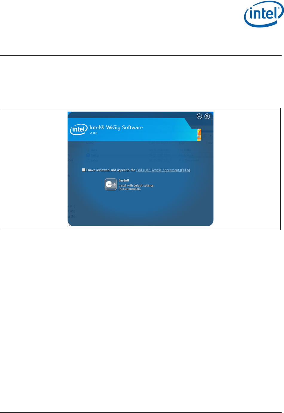
Figure 2-1 End User License Agreement screen
Check I have reviewed and agree to the EULA and click Install. This will install the operational
WiGig software for the NB.
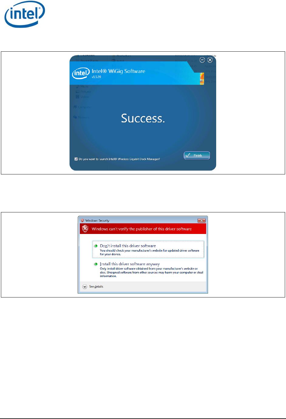
2. When the application is successfully installed, check the Do you want to launch Intel
®
Wireless
Gigabit Dock Manager? option. Click Finish.
You will be able to launch the Intel
®
Wireless Dock Manager application from the desktop
shortcut later if you do not check this option.
Software Install
Intel
®
Wireless Gigabit v2.0
October 2015 User Guide
Document Number: 537178-3.3 Intel Confidential 11
Figure 2-2 Success screen
3. During the first installation, the device driver is installed. If the Windows Security message
shown in Figure 2-3 appears, choose Install this driver software anyway to continue the
installation.
Figure 2-3 Windows security message
Note: To avoid this window, run the certificate file (iCert.spc) from the Certificates layout.
Run setup.exe –q from a command line to run the installer in silent mode.
§
WiGig Application User Manual for Win 7/8/8.1
Intel
®
Wireless Gigabit v2.0
User Guide October 2015
12 Intel Confidential Document Number: 537178-3.3
3 WiGig Application User Manual for
Win 7/8/8.1
3.1 User manual
The Intel
®
Wireless Dock Manager is a dedicated application that runs on the client and allows the
user to find, connect to, and configure docks.
LEDs on the dock, and an OSD (On Screen Display) on the monitor connected to the dock, provide
further feedback about the dock status, and assist the user in performing actions.
The activity button on the dock is used in some of the flows (like pairing and
connection/disconnection).
3.1.1 Launching the Intel
®
Wireless Dock Manager
The Intel
®
Wireless Dock Manager starts automatically with Windows.
To invoke the Intel
®
Wireless Dock Manager interface, double-click the icon on the desktop,
labeled Intel
®
Wireless Dock Manager.
Alternatively, double-click the WiGig tray icon , or right-click and choose View available docks.
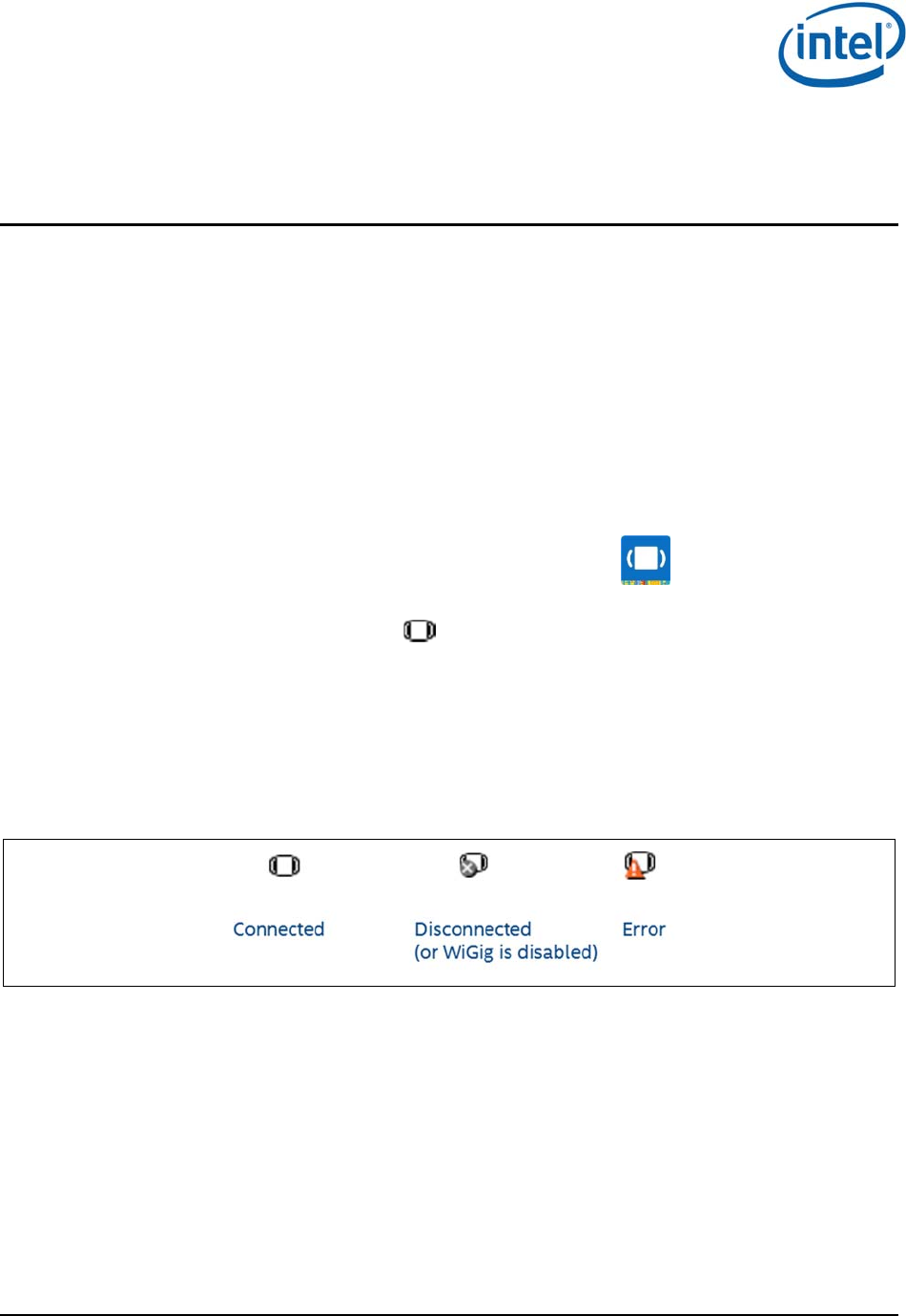
A dedicated tray icon can initiate the Intel
®
Wireless Dock Manager and indicate the relevant status as
shown in Figure 3-1:
Connected: The NB is connected to a dock
Disconnected: The NB is not connected to a dock
Error: Error while connecting or weak connection (hover to see the error reason)
Figure 3-1 Tray icon indications
Note: The Intel
®
Wireless Dock Manager application keeps running from the system tray even if
you click the X (close window) icon on the application.
3.1.2 Making the first connection
1. Turn on the power on your dock. When the dock is ready to accept connections, the external
monitor will light up and show the welcome OSD screen in Figure 3-2.
WiGig Application User Manual for Win 7/8/8.1
Intel
®
Wireless Gigabit v2.0
October 2015 User Guide
Document Number: 537178-3.3 Intel Confidential 13
Figure 3-2 Welcome OSD screen
2. This screen remains until the connection is made. After a few minutes of inactivity, the monitor
turns off to conserve power. Press the dock activity button to wake up the monitor and continue
with the connection.
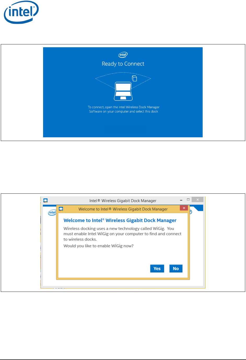
3. Enable WiGig on your client. WiGig comes disabled out-of-the-box to conserve battery life until
the first time WiGig is needed. When the Wireless Dock Manager is launched for the first time,
the Welcome screen appears.
Figure 3-3 Welcome screen
4. Choose Yes to enable WiGig. Shortly after, WiGig will start scanning for docks in your vicinity.
You will see a screen similar to Figure 3-4.
WiGig Application User Manual for Win 7/8/8.1
Intel
®
Wireless Gigabit v2.0
User Guide October 2015
14 Intel Confidential Document Number: 537178-3.3
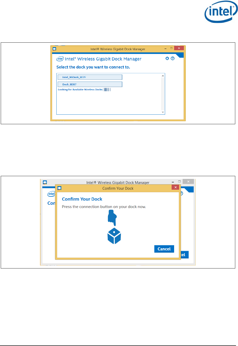
Figure 3-4 Dock select
5. Choose the dock you wish to connect to by clicking it.
Note: Since this is the first time you are connecting to this dock, you will need to pair with it.
Pairing creates a set of authentication keys that uniquely identify your client and dock
pair, and allow them to communicate in a secured, encrypted manner over-the-air.
6. Press the connection button on your dock to confirm it, as indicated in Figure 3-5.
Figure 3-5 Dock confirmation screen
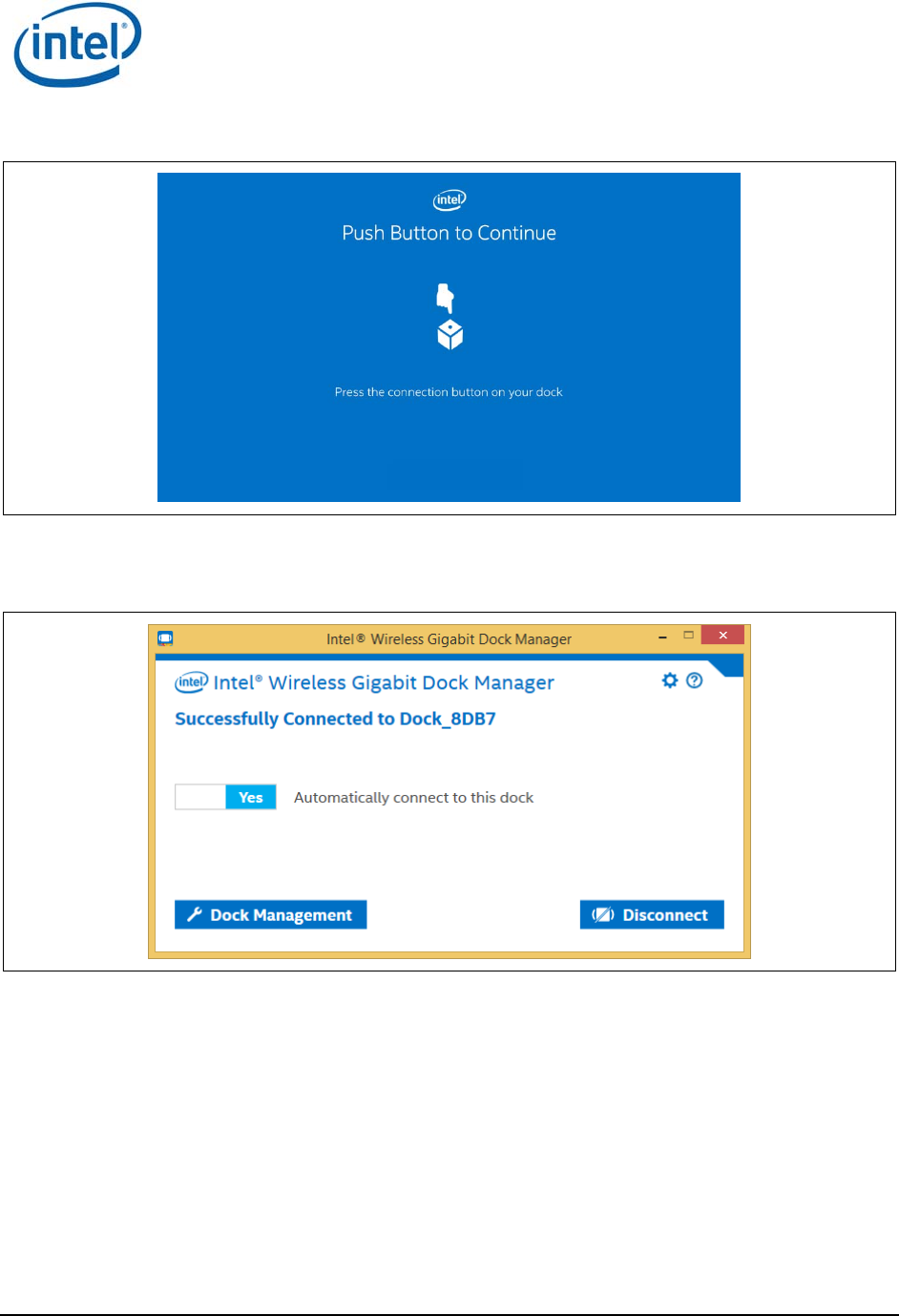
7. A corresponding OSD will appear on the external monitor, as shown in Figure 3-6.
WiGig Application User Manual for Win 7/8/8.1
Intel
®
Wireless Gigabit v2.0
October 2015 User Guide
Document Number: 537178-3.3 Intel Confidential 15
Figure 3-6 OSD screen
8. Press the activity button on the dock to complete the pairing process. The Connected screen
appears shortly after, as shown in Figure 3-7.
Figure 3-7 Dock Connected screen
Note: A successful connection is also indicated by the dock LED (if available), and the external
monitor and USB devices being connected and enumerated on your client (you will hear
the Window’s gling-gling hot-plug audio cues).
Congratulations! You have made your first wireless docking connection.
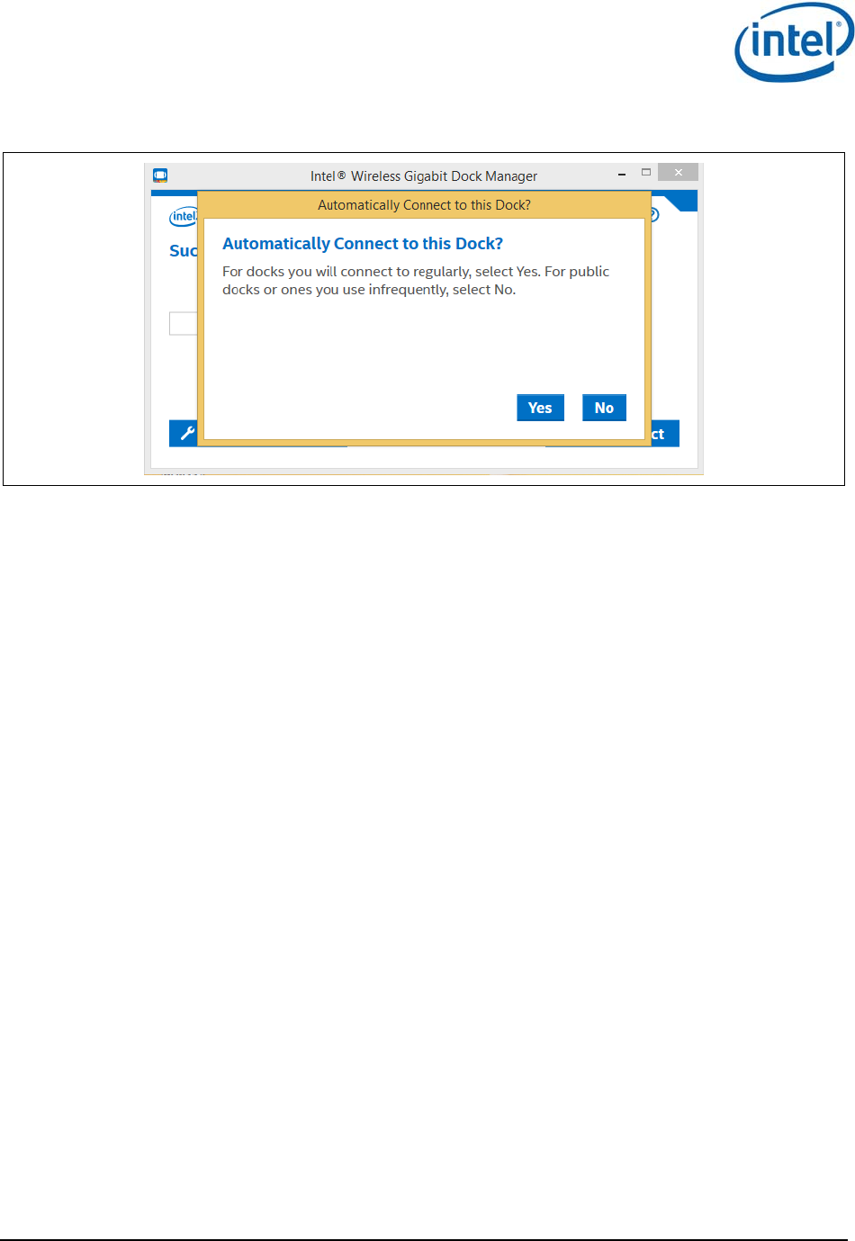
3.1.3 Automatic connection default
While connecting to the dock for the first time, you will see the message to set the dock to be
automatically connected or not, as shown in Figure 3-8.
WiGig Application User Manual for Win 7/8/8.1
Intel
®
Wireless Gigabit v2.0
User Guide October 2015
16 Intel Confidential Document Number: 537178-3.3
Figure 3-8 Automatically Connect to this Dock
For docks you connect to regularly, select Yes. For public docks or ones you use rarely, select No.
3.1.4 Automatic connections
If a dock is set to connect automatically, WiGig will attempt to automatically connect to this dock once
in range. To this end, WiGig keeps scanning in the background, while consuming very little power.
To connect, simply place your client (assumed to be in S0) near the dock. Within several seconds,
WiGig will discover the dock and will connect to it automatically. You do not have to invoke the
Wireless Dock Manager, open the lid or take any action, just wait until the external screen comes up
and USB devices are enumerated, and you can start working.
When successfully connected to a dock, the dock LED changes color (color is specific to dock vendor).
Note: For the connection to be fully completed automatically, as described above, the client
needs to be powered on and active (such as in S0). If the client is in S3, WiGig will
automatically discover the dock, and then you can use the dock button to wake up the
client and complete the docking procedure. See Section 3.1.6 for more details. Ability to
wake up the client from the dock is vendor specific and is configured in the BIOS.
WiGig Application User Manual for Win 7/8/8.1
Intel
®
Wireless Gigabit v2.0
October 2015 User Guide
Document Number: 537178-3.3 Intel Confidential 17
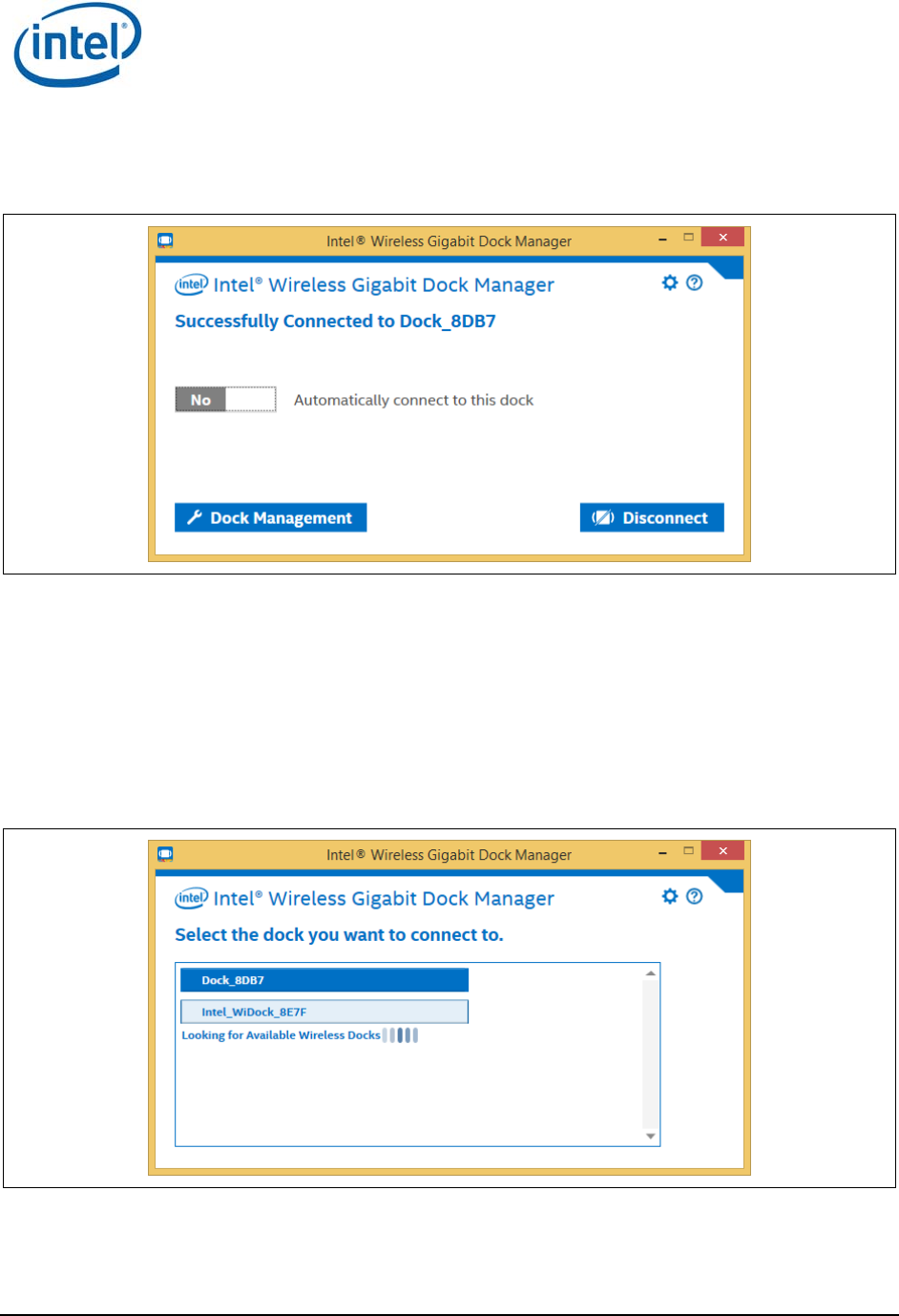
You can disable auto-connect by changing the toggle on the main Wireless Dock Manager screen while
connected, as shown in Figure 3-9.
Figure 3-9 Disabling the auto-connect setting
You can only change a dock between automatic and manual connection when you are actively
connected to the dock.
Once auto-connect is disabled, the client will no longer connect automatically and you will have to
manually select the dock from the client, as described in Section 3.1.5.
3.1.5 Manually connecting to a dock
To manually connect to a dock, choose the dock from the list of docks by clicking on it, as shown in
Figure 3-10.
Figure 3-10 Manual dock connection
Docks that you have already paired with in the past will appear with a dark background color. Docks
that you have never paired with will appear with a light background color.
The list is being refreshed automatically, as WiGig keeps scanning in the background.

WiGig Application User Manual for Win 7/8/8.1
Intel
®
Wireless Gigabit v2.0
User Guide October 2015
18 Intel Confidential Document Number: 537178-3.3
Another method to connect to a dock is via the tray icon. If there is only a single paired dock in range
(that is, a dock you have already paired with in the past), you can right-click the tray icon and choose
Connect to <dock name>. Right-clicking when there is more than one paired dock in range, or no
paired docks, will give you the option to open the Wireless Dock Manager (View available docks),
where you can choose your desired dock from the list.
When successfully connected to a dock, the dock LED changes color (color is specific to dock vendor).
3.1.6 Automatic connection in S3 (depends on BIOS
configuration)
When getting in range with a paired dock that is set to auto-connect, and the client is sleeping (S3),
the WiGig radio will discover the dock and establish a low power link to it, known as low-power
connected. This mode may be indicated by the LED changing color.
While in this mode, the system is kept in its low power state (S3), and WiGig will wait for an indication
from the dock side to wake up the system and complete the connection procedure. This can be
achieved by pressing the activity button on the dock. When the button is pressed, the client is moved
to S0, and the connection completes automatically.
Once fully connected, the dock LED may change color.
3.1.7 Automatic connection in connected standby
When getting in range with a paired dock that is set to auto-connect, and the client is connected
standby low-power mode, the WiGig radio will automatically connect to the dock. The devices
connected to the dock will be connected and enumerated on the client, however the external monitor
will not come up and the system will remain in connected standby.
To take the system out of connected standby, and light up the screen, press the activity button on the
dock, or alternatively click the mouse or press the keyboard.
3.1.8 Disconnecting from the dock
There are several methods in which you can disconnect an active connection:
1. First, you can simply take your client and walk out of range from the dock. WiGig will eventually
lose the link, and the dock will be disconnected. Once disconnected, WiGig automatically starts
scanning again to discover auto-connect docks in range.
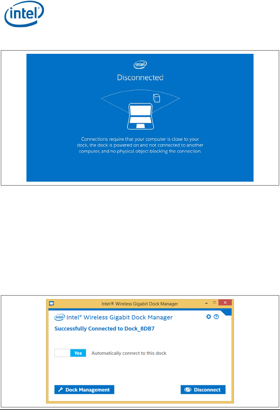
This method is also known as auto-disconnect. In this case, the OSD will display the screen
pictured in Figure 3-11 after disconnecting.
WiGig Application User Manual for Win 7/8/8.1
Intel
®
Wireless Gigabit v2.0
October 2015 User Guide
Document Number: 537178-3.3 Intel Confidential 19
Figure 3-11 Dock disconnection screen
Note: Disconnecting by getting out of range (auto-disconnect) is experienced by the system as a
USB surprise-removal event. While Windows has become better and better over the years
with handling surprise removals, there is still always a chance of data loss/corruption
when surprise-removing USB Mass Storage devices connected to the dock (other devices,
such as HID, USB LAN, USB audio, etc., do not suffer). If this is a concern, for example, if
you have a Mass Storage device connected to your dock, and you have just recently
finished accessing this device, it may be advisable to safely remove this USB device (right-
click on the USB icon in the system tray), or to disconnect WiGig manually, as described
below. In any case, it is advised to act in a similar manner to undocking from a wired
dock, as the same issues are present there as well.
2. To manually disconnect, invoke the Wireless Dock Manager and click the Disconnect button on
the main screen. Alternatively, you can right-click the tray icon and choose Disconnect from
<dock name>.
Figure 3-12 Manual disconnect option
WiGig Application User Manual for Win 7/8/8.1
Intel
®
Wireless Gigabit v2.0
User Guide October 2015
20 Intel Confidential Document Number: 537178-3.3
3. Another method to manually disconnect is to press down and hold the activity button on the
dock for more than four seconds. This method is especially useful for closed-lid operations, or if
you are trying to manually disconnect a system where you cannot access the Wireless Dock
Manager (like when the system is locked and you do not know the password).
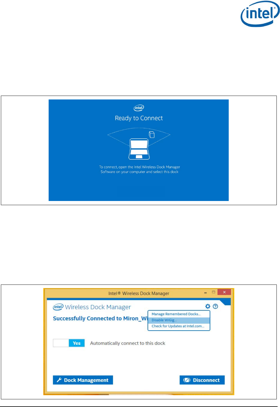
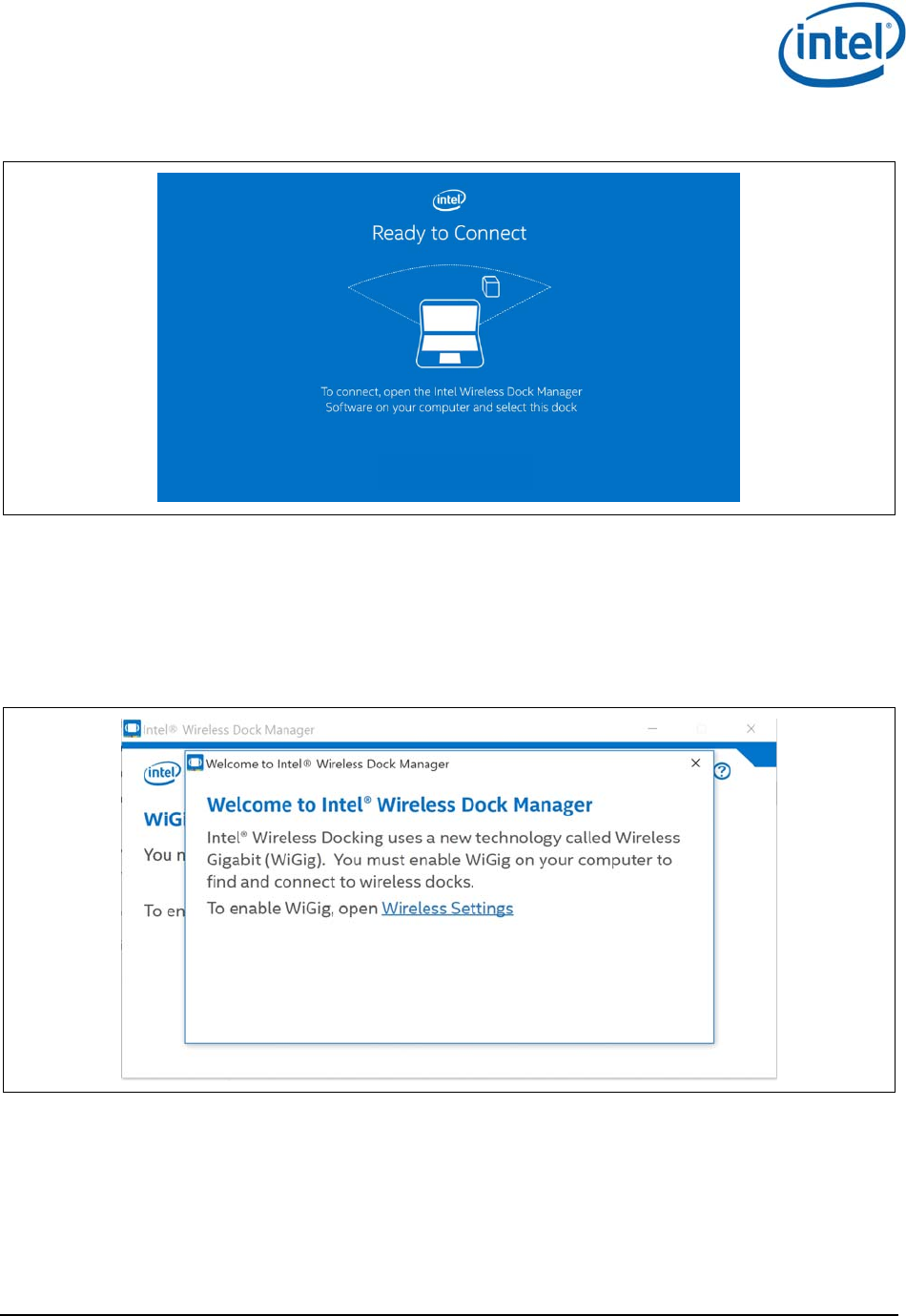
Once disconnected, the dock LED changes color (color is specific to dock vendor), and the OSD
shows the Ready to Connect screen, as shown in Figure 3-13.
Figure 3-13 Ready to connect screen
Note: Manually disconnecting from a dock that is set to connect automatically will temporarily
disable auto-connect to this dock. This is to prevent the connection from being recovered
immediately. To re-enable automatic connections to this dock, the client needs to get out
of range and then return, or to do an Sx cycle (S0S3S0).
3.1.9 Disabling and enabling WiGig
1. To disable WiGig, click on the gear icon in the upper right of the main Wireless Dock Manager
screen, shown in Figure 3-14. A popup-menu will come up.
Figure 3-14 Disable WiGig using the gear icon
WiGig Application User Manual for Win 7/8/8.1
Intel
®
Wireless Gigabit v2.0
October 2015 User Guide
Document Number: 537178-3.3 Intel Confidential 21
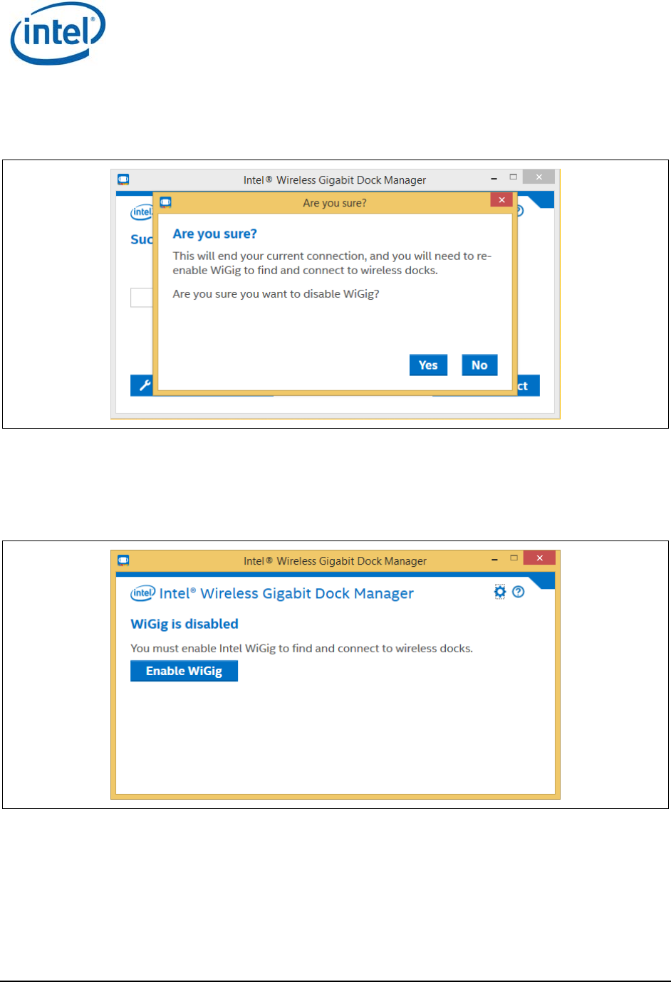
2. Choose the first menu option Disable WiGig. A warning will show up, similar to the one in Figure
3-15 (depending on whether you are currently connected or not).
Figure 3-15 Disable WiGig warning screen
3. Choose Yes to disable WiGig.
4. When WiGig is disabled, you cannot find and connect to wireless docks; the screen shown in
Figure 3-16 comes up. Disabling minimizes the power consumption of the WiGig radio in the
client.
Figure 3-16 WiGig disable confirmation screen
5. To enable WiGig, press the Enable WiGig button.
WiGig Application User Manual for Win 7/8/8.1
Intel
®
Wireless Gigabit v2.0
User Guide October 2015
22 Intel Confidential Document Number: 537178-3.3
3.2 Changing dock settings
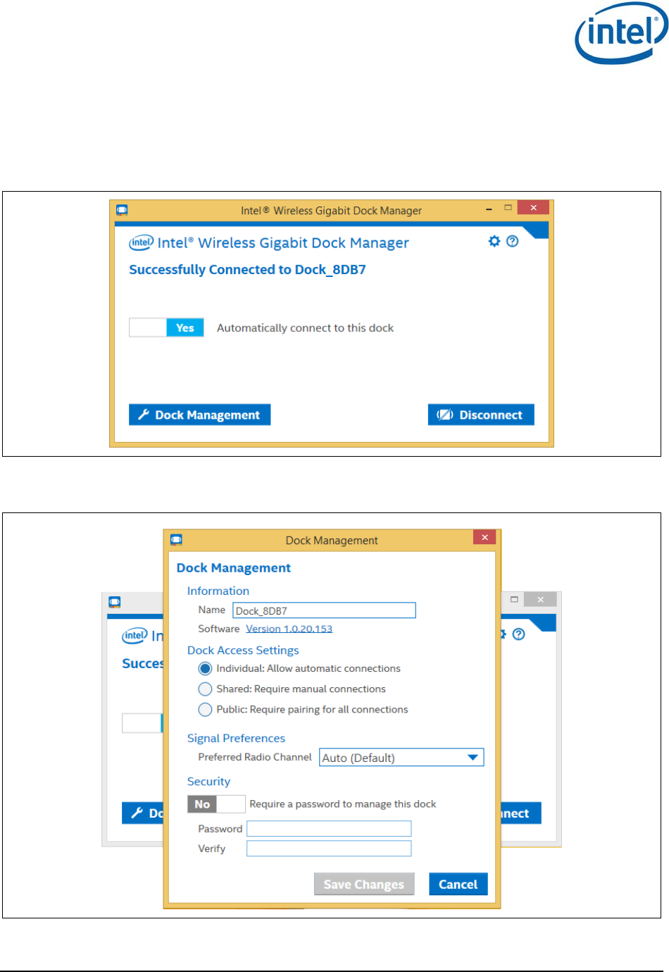
1. To access the dock settings, click the Dock Management button on the main Wireless Dock
Manager screen while connected to a dock, as shown in Figure 3-17.
Figure 3-17 Dock management button
2. This will open up the Dock Management screen, as shown in Figure 3-18.
Figure 3-18 Dock management screen
3. In Dock Management, you can configure the following settings:
– Information

WiGig Application User Manual for Win 7/8/8.1
Intel
®
Wireless Gigabit v2.0
October 2015 User Guide
Document Number: 537178-3.3 Intel Confidential 23
Name: This field determines how will the dock be called and presented in the scan list in
the Wireless Dock Manager. This field accepts only Latin letters, digits, and a few special
characters such as space and underscore.
Note: The factory setting for dock name is a prefix Dock and an automatic suffix of the last four
nibbles of the MAC address of the dock. This helps users to distinguish between similar
docks whose names have not been customized. Once the user changes the dock name,
the last four nibbles of the MAC address are no longer appended to it. To re-enable this
behavior, the dock must be reset to the factory defaults by pressing the recovery button
on the dock for ten seconds.
Software: This shows the version of the currently installed software. Clicking this item
will allow you to manually update your dock software, as described in Section Error!
Reference source not found.. Also, when an update is available for your dock, it will
show up next to the version number. Click the Update Available link to start the software
update procedure.
– Dock Access Settings
Individual: Allows automatic connections. This setting enables the auto-connect toggle
on connected clients, as described in Section 3.1.3. This is the only setting with which
the dock can be automatically connected to, and is particularly suitable for private docks
for individuals.
Shared: Requires manual confirmation. This setting forces manual connections by
disabling the auto-connect toggle on connected clients. This setting is particularly
suitable for shared docks in multi-users environments, where it may be undesirable to
allow automatic connection to prevent users from inadvertently connecting to the dock
while in range (remember that a dock that is currently connected to a user cannot
accept other user’s connections, and will not be seen in their scan list).
Public: Requires pairing for all connections. This settings forces the user to pair on
every connection (such as. pairing data is lost upon disconnect). This is the most secure
setting, and is mostly suitable for docks where the convenience of connection is less of a
concern, for example in airports, cafes or hotels.
– Signal Preferences
Preferred Radio Channel: Allows you to assign a specific operating channel, or enable
automatic selection by the dock. It is recommended to leave this as Auto, as this will
allow the dock to select the best channel to operate in, based on interference and other
factors.
– Password
Enable this to assign a password for protecting the dock setting page, preventing
unauthorized access.
3.3 Dock software update
Your dock software can be upgraded over-the-air from the client.
3.3.1 Update during connection
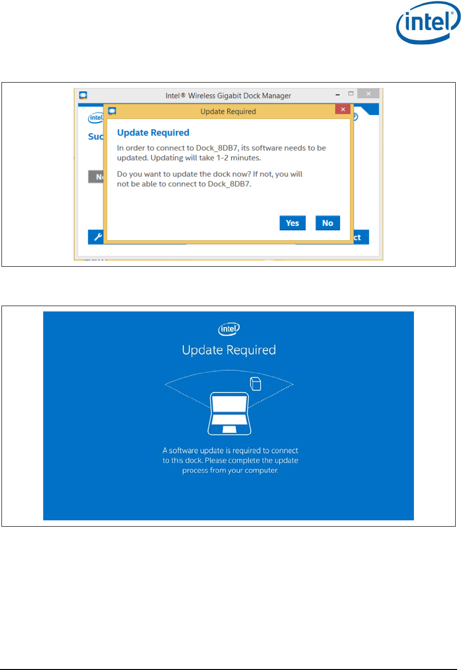
1. When connecting to the dock, the Wireless Dock Manager might inform the user of mandatory
dock software update.
2. On mandatory dock software updates, the Wireless Dock Manager will present the message
shown in Figure 3-19 while trying to connect.
WiGig Application User Manual for Win 7/8/8.1
Intel
®
Wireless Gigabit v2.0
User Guide October 2015
24 Intel Confidential Document Number: 537178-3.3
Figure 3-19 Dock software update required screen
3. In addition, the OSD on the external monitor will show the following message in Figure 3-20.
Figure 3-20 OSD update screen
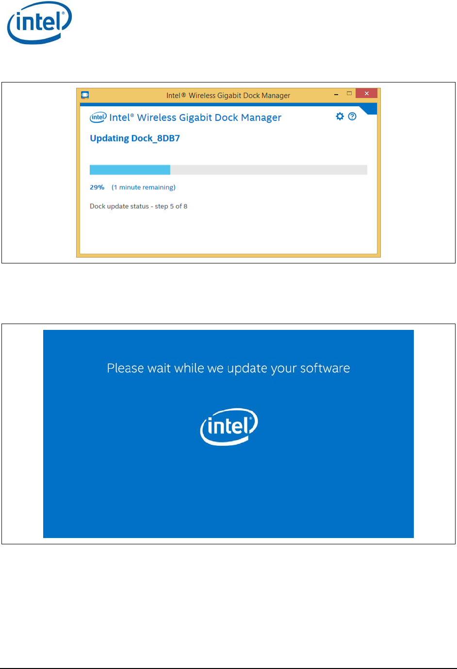
4. Choosing No will disconnect. The user cannot connect and work with this dock without
performing a software update.
5. Choosing Yes will start the dock software update process. A screen similar to the one in Figure
3-21 will be presented, with the bar indicating progress.
WiGig Application User Manual for Win 7/8/8.1
Intel
®
Wireless Gigabit v2.0
October 2015 User Guide
Document Number: 537178-3.3 Intel Confidential 25
Figure 3-21 Dock update progress
6. During the software update process, the dock LED changes color (color is specific to dock
vendor), and the OSD will show the screen in Figure 3-22; the screen should have progress
bars.
Figure 3-22 OSD update progress screen
7. Once the update process is complete, the dock will be reset and the client will either
automatically re-connect (auto-connect is enabled) or the user will need to manually re-connect
to the dock (auto-connect is disabled).
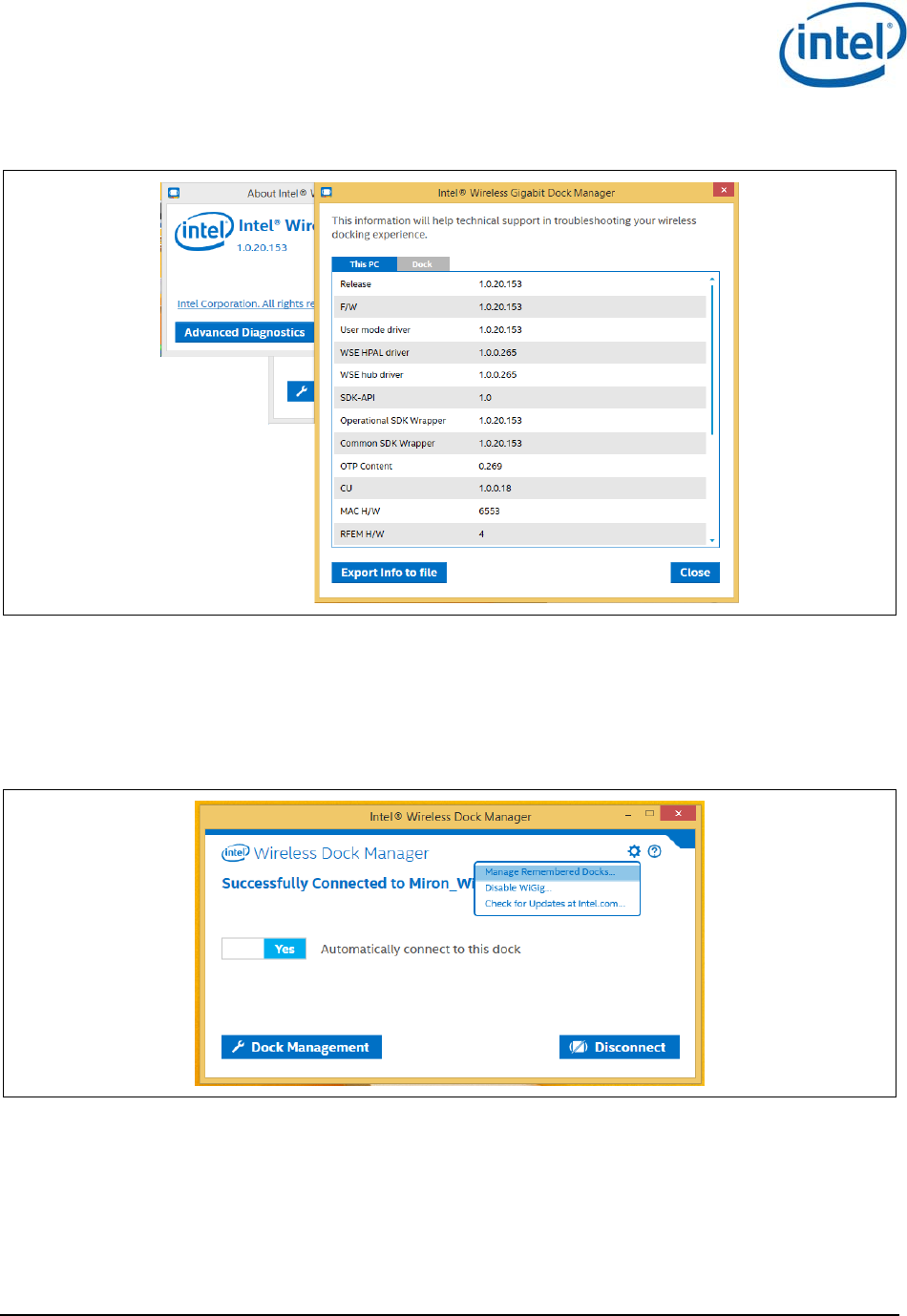
3.4 Diagnostic information
Information shown in diagnostics window will help technical support in troubleshooting your wireless
docking experience. In order to open diagnostics window, press the Advanced Diagnostics button in
the About window.
WiGig Application User Manual for Win 7/8/8.1
Intel
®
Wireless Gigabit v2.0
User Guide October 2015
26 Intel Confidential Document Number: 537178-3.3
Figure 3-23 Advanced diagnostics window
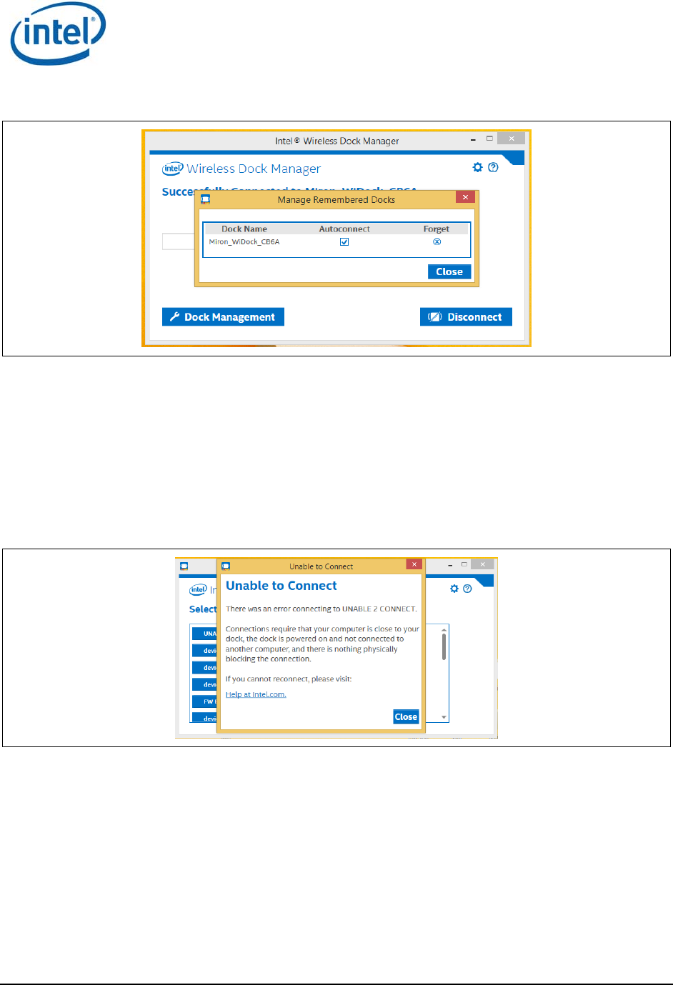
3.5 Managing docks
User may manage docks he has previously connected to. For each dock, user may delete the dock or
remove the autoconnect option. To manage docks, click on the Manage Remembered Dock dialog from
the settings button, as shown in Figure 3-24 and Figure 3-25.
Figure 3-24 Choose manage remember docks
WiGig Application User Manual for Win 7/8/8.1
Intel
®
Wireless Gigabit v2.0
October 2015 User Guide
Document Number: 537178-3.3 Intel Confidential 27
Figure 3-25 Manage dock autoconnect feature
3.6 Notification messages
There are notification messages that inform user about the different application activities, like possible
limitations or errors.
3.6.1 Unable to connect
The unable to connect message is displayed if there is an error during the connection or pairing
process, as shown in Figure 3-26.
Figure 3-26 Unable to connect
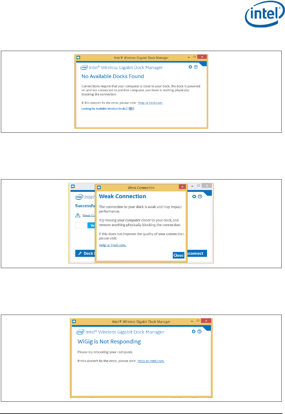
3.6.2 No available docks found
As shown in Figure 3-27, the no available docks found message is displayed if scanning was done but
no docks have been detected.
WiGig Application User Manual for Win 7/8/8.1
Intel
®
Wireless Gigabit v2.0
User Guide October 2015
28 Intel Confidential Document Number: 537178-3.3
Figure 3-27 No docks found
3.6.3 Weak connection
The weak connection message is displayed if the connection is weak but connected, as shown in
Figure 3-28.
Figure 3-28 Weak connection
3.6.4 WiGig not responding
The WiGig is not responding message is displayed if WiGig driver or device is not responding, as
shown in Figure 3-29.
Figure 3-29 WiGig not responding
WiGig Application User Manual for Win 7/8/8.1
Intel
®
Wireless Gigabit v2.0
October 2015 User Guide
Document Number: 537178-3.3 Intel Confidential 29
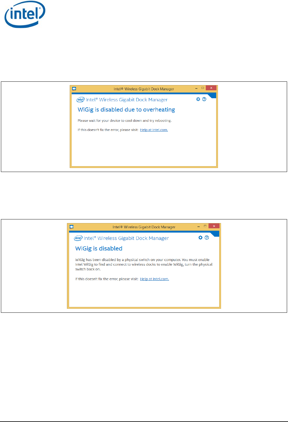
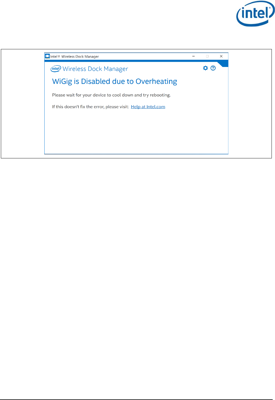
3.6.5 WiGig disabled – critical temperature
The WiGig is disabled due to overheating message is displayed if WiGig driver or device is disabled due
to a critical temperature error, as shown in Figure 3-30.
Figure 3-30 WiGig disabled due to overheating
3.6.6 WiGig disabled by hardware RF kill switch
The WiGig is disabled message is displayed if WiGig driver or device is disabled by the physical radio
on/off switch, as shown in Figure 3-31.
Figure 3-31 WiGig disabled by hardware RF Kill switch

WiGig Application User Manual for Win 7/8/8.1
Intel
®
Wireless Gigabit v2.0
User Guide October 2015
30 Intel Confidential Document Number: 537178-3.3
3.6.7 WiGig disabled by airplane mode
The WiGig is disabled message is displayed if WiGig driver or device is disabled because the device is
in airplane mode, as shown in Figure 3-32.
Figure 3-32 WiGig disabled by airplane mode
§
WiGig Application User Manual for Windows 10*
Intel
®
Wireless Gigabit v2.0
October 2015 User Guide
Document Number: 537178-3.3 Intel Confidential 31
4 WiGig Application User Manual for
Windows 10*
4.1 User manual
This chapter will be very similar to the previous chapter and will contain the Wigig behavior in
Windows 10* OS.
In Windows 10*, the OS will control the network related functionality. This include handling the radio
state, scan, connect and manage the profiles. The OS will control this via the setting and the action
center pane as will be demonstrate below.
The Intel
®
Wireless Dock Manager is a dedicated application that runs on the client and allows the
user to do all the activities that are not related to network management like manage the dock, get
diagnostic info, do FWU etc.
LEDs on the dock, and an OSD (On Screen Display) on the monitor connected to the dock, provide
further feedback about the dock status, and assist the user in performing actions.
The activity button on the dock is used in some of the flows (like pairing and
connection/disconnection).
4.1.1 Launching the Intel
®
Wireless Dock Manager
The Intel
®
Wireless Dock Manager starts automatically with Windows.
To invoke the Intel
®
Wireless Dock Manager interface, double-click the icon on the desktop,
labeled Intel
®
Wireless Wireless Dock Manager.
Alternatively, double-click the WiGig tray icon while the device is connected to a dock (the
connected icon as shown in Figure 3-1)
The Intel
®
Wireless Dock Manager application keeps running as an application even if you click the X
(close window) icon on the application in order to kill it you must use the task manager.
4.1.2 Making the first connection
Turn on the power on your dock. When the dock is ready to accept connections, the external
monitor will light up and show the welcome OSD screen in Figure 4-1.
WiGig Application User Manual for Windows 10*
Intel
®
Wireless Gigabit v2.0
User Guide October 2015
32 Intel Confidential Document Number: 537178-3.3
Figure 4-1 Welcome OSD screen
1. This screen remains until the connection is made. After a few minutes of inactivity, the monitor
turns off to conserve power. Press the dock activity button to wake up the monitor and continue
with the connection.
2. Enable WiGig on your client. WiGig comes disabled out-of-the-box to conserve battery life until
the first time WiGig is needed. When the Wireless Dock Manager is launched for the first time,
the Welcome screen appears.
Figure 4-2 Welcome screen
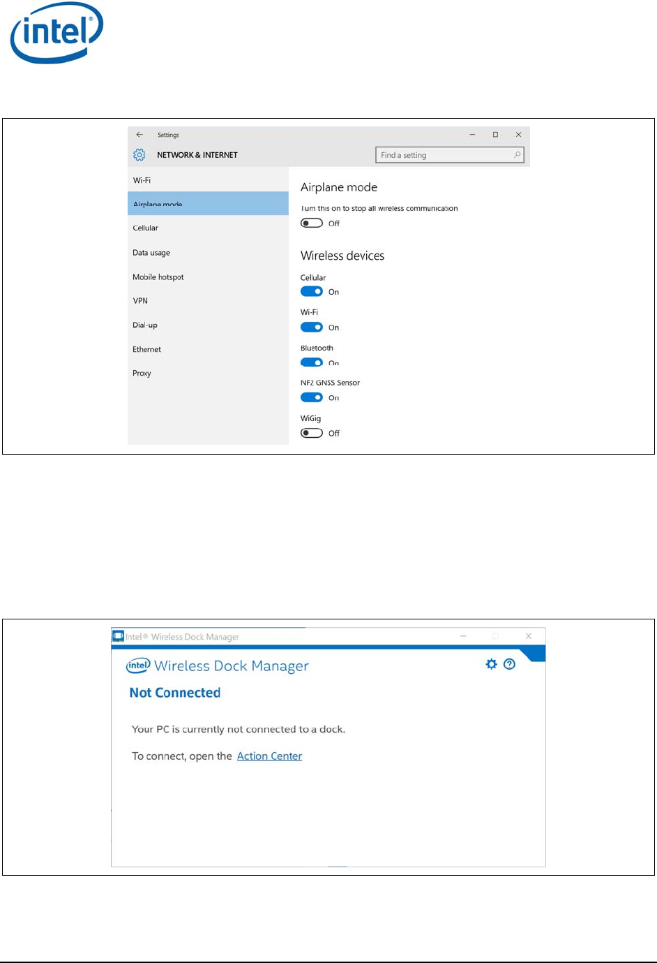
3. Clicking on the Wireless Settings link will send you to the OS Airplane mode page (Figure 4-3).
In this page you will be able to turn on (and later off in case you want) the WiGig RF mode in
addition to other devices RF state.
WiGig Application User Manual for Windows 10*
Intel
®
Wireless Gigabit v2.0
October 2015 User Guide
Document Number: 537178-3.3 Intel Confidential 33
Figure 4-3 Network & Internet screen
4. Alternative way to get to this page is via settings: Network & Internet -> Airplane mode.
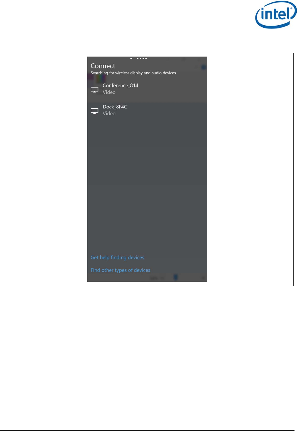
5. Once you set the WiGig radio button to on, you will be able to find docks in the range. In
Windows 10* you will not be able to see the scan results in the Connect pane and not in the
Intel
®
Wireless Dock Manager.
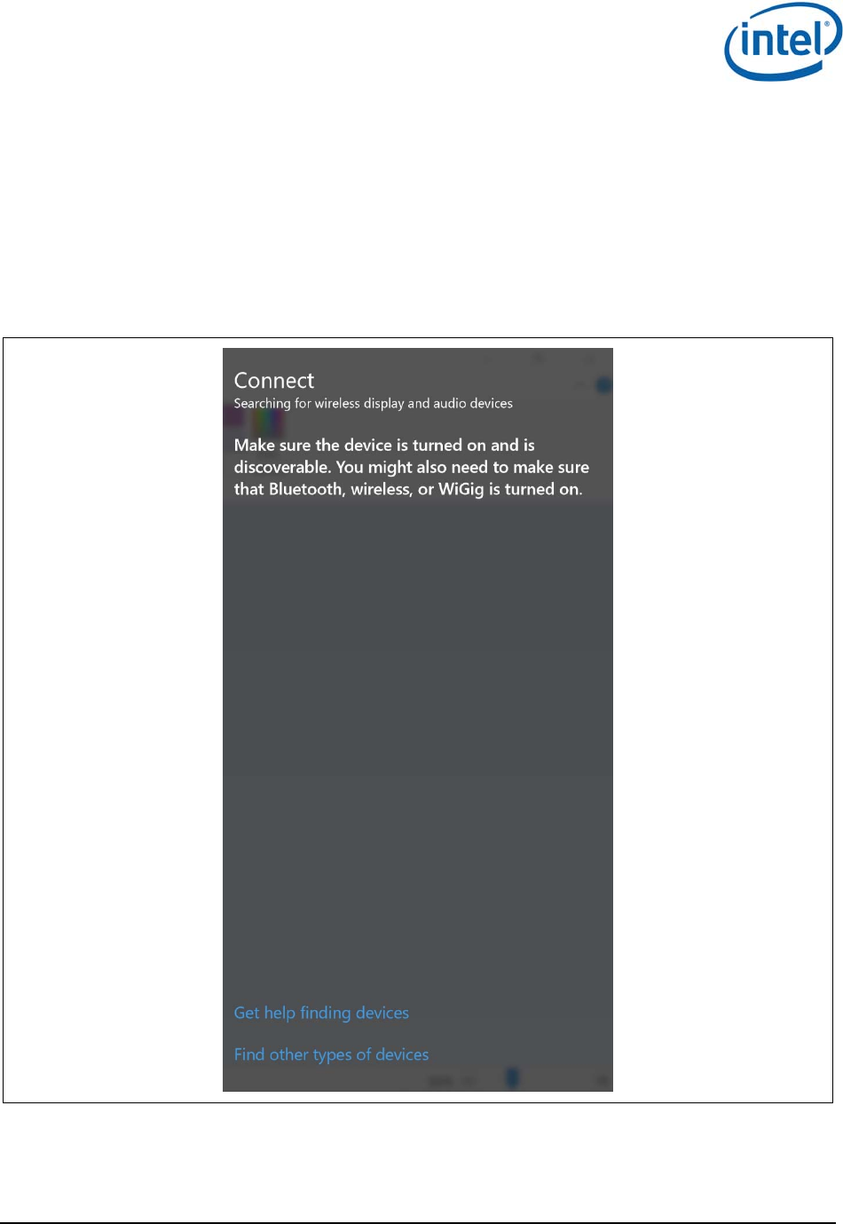
6. In order to get to the OS Connect pane, you click on the Action Center link (Figure 4-4) or press
the keyboard shortcut Win+k and the Connect pane will open on the right side of the monitor
(Figure 4-5).
Figure 4-4 Dock select
WiGig Application User Manual for Windows 10*
Intel
®
Wireless Gigabit v2.0
User Guide October 2015
34 Intel Confidential Document Number: 537178-3.3
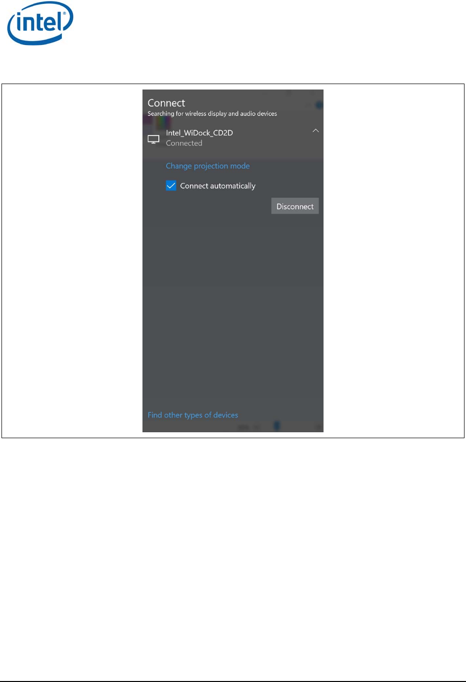
Figure 4-5 Connect pane
7. Choose the dock you wish to connect to by clicking it in the Connect pane.
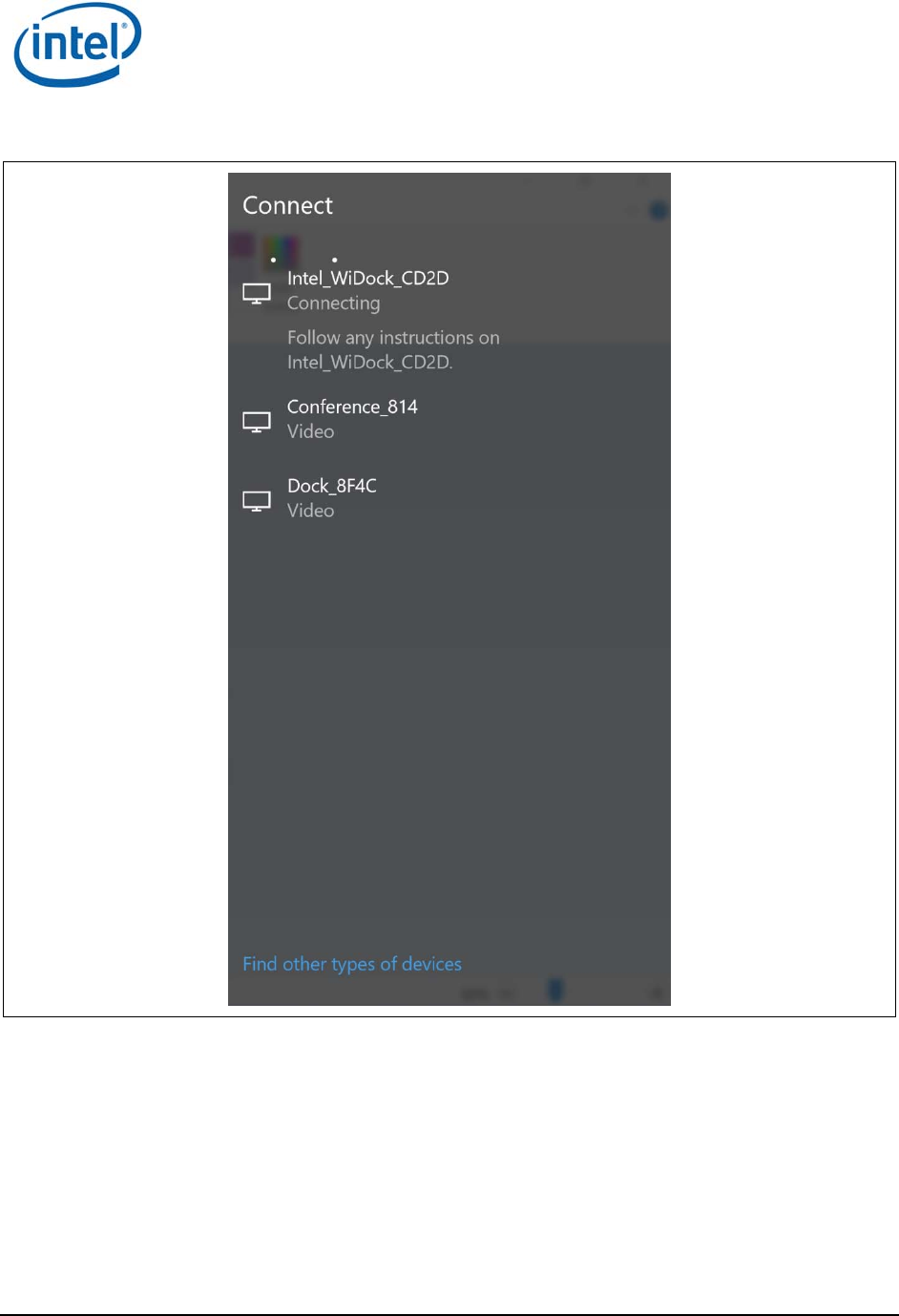
Note: Since this is the first time you are connecting to this dock, you will need to pair with it.
Pairing creates a set of authentication keys that uniquely identify your client and dock
pair, and allow them to communicate in a secured, encrypted manner over-the-air.
8. After connecting, you will get an instruction in the Connect pane to follow the instructions on the
dock Figure 4-6.
WiGig Application User Manual for Windows 10*
Intel
®
Wireless Gigabit v2.0
October 2015 User Guide
Document Number: 537178-3.3 Intel Confidential 35
Figure 4-6 Connect pane during connecting stage
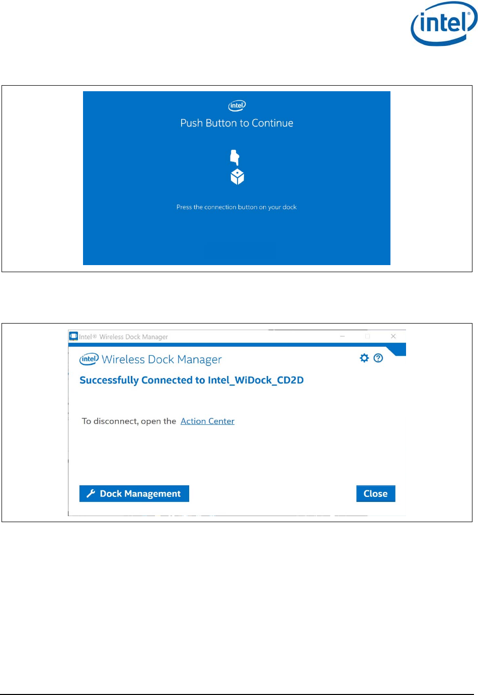
9. A corresponding OSD will appear on the external monitor, as shown in Figure 4-7.
10. Unlike in Win7/8/8.1, you will not see the indication to push the dock button on Intel
®
Wireless
Dock Manager.
WiGig Application User Manual for Windows 10*
Intel
®
Wireless Gigabit v2.0
User Guide October 2015
36 Intel Confidential Document Number: 537178-3.3
Figure 4-7 OSD screen
11. Press the activity button on the dock to complete the pairing process. The Connected screen
appears shortly after, as shown in Figure 4-8.
Figure 4-8 Dock Connected screen
Note: A successful connection is also indicated by the dock LED (if available), and the external
monitor and USB devices being connected and enumerated on your client (you will hear
the Window’s gling-gling hot-plug audio cues).
In addition you are also able to see that you are connected via the Connect pane by clicking the Action
Center link, or by pressing keyboard shortcut Win+K as shown in Figure 4-9.
WiGig Application User Manual for Windows 10*
Intel
®
Wireless Gigabit v2.0
October 2015 User Guide
Document Number: 537178-3.3 Intel Confidential 37
Figure 4-9 Dock connected screen
Congratulations! You have made your first wireless docking connection.
4.1.3 Automatic connection default
This section is not applicable in Win10 as in Win7/8/8.1. Instead in Windows 10* the dock will already
be in automatically connect mode.
4.1.4 Automatic connections
If a dock is set to connect automatically, WiGig will attempt to automatically connect to this dock once
in range. To this end, WiGig keeps scanning in the background, while consuming very little power.
To connect, simply place your client (assumed to be in S0) near the dock. Within several seconds,
WiGig will discover the dock and will connect to it automatically. You do not have to invoke the
Wireless Dock Manager, open the lid or take any action, just wait until the external screen comes up
and USB devices are enumerated, and you can start working.
When successfully connected to a dock, the dock LED changes color (color is specific to dock vendor).
Note: For the connection to be fully completed automatically, as described above, the client
needs to be powered on and active (such as in S0). If the client is in S3, WiGig will
automatically discover the dock, and then you can use the dock button to wake up the
WiGig Application User Manual for Windows 10*
Intel
®
Wireless Gigabit v2.0
User Guide October 2015
38 Intel Confidential Document Number: 537178-3.3
client and complete the docking procedure. See Section 3.1.6 for more details. Ability to
wake up the client from the dock is vendor specific and is configured in the BIOS.
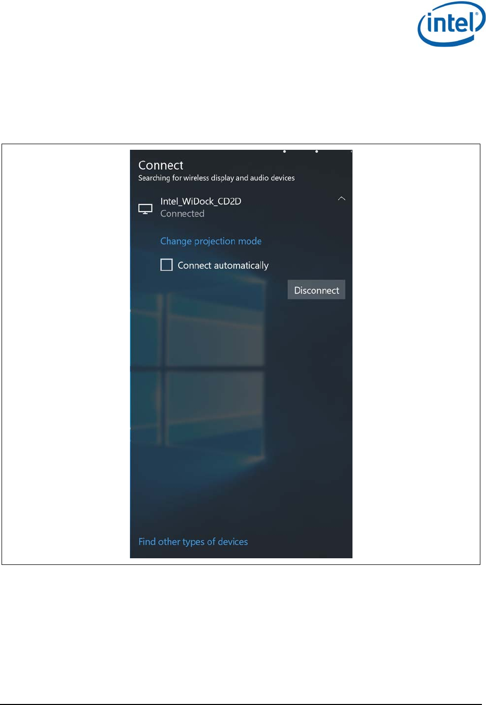
You can disable auto-connect by deselecting the Connect automatically check box while connected, as
shown in Figure 4-10.
Figure 4-10 Disabling the auto-connect setting
You can only change a dock between automatic and manual connection when you are actively
connected to the dock.
Once auto-connect is disabled, the client will no longer connect automatically and you will have to
manually select the dock from the client, as described in Section 3.1.5.
4.1.5 Manually connecting to a dock
When the dock is defined as manual, the connection is done similarly to the connection flow that was
describe above without the stage where the user is requested to push the button.
WiGig Application User Manual for Windows 10*
Intel
®
Wireless Gigabit v2.0
October 2015 User Guide
Document Number: 537178-3.3 Intel Confidential 39
4.1.6 Automatic connection in S3 (depends on BIOS
configuration)
Same as in Section 3.1.6
4.1.7 Automatic connection in connected standby
Same as in Section 3.1.7
4.1.8 Disconnecting from the dock
Same as in Section 3.1.8.
The only differentiation is in order to manually disconnect, the user cannot disconnect from the Intel
®
Wireless Dock Manager but instead has to do it from the Connect pane.
4.1.9 Disabling and enabling WiGig
1. In Win10 the ability to disable the WiGig is done only via the OS Airplane mode setting page
(settings-> Network & Internet -> Airplane mode).
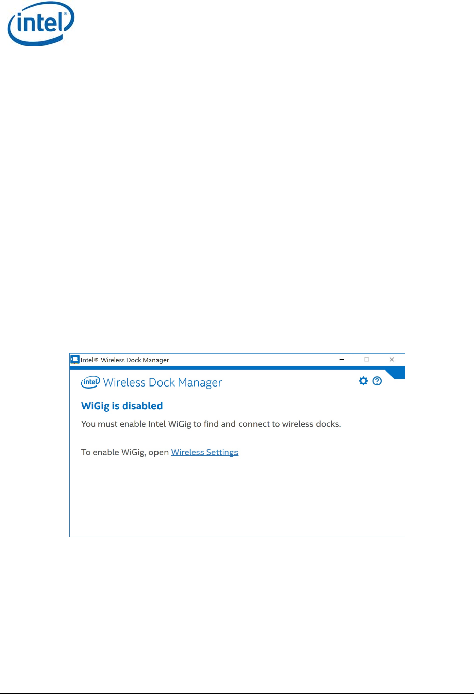
2. When WiGig is disabled, you cannot find and connect to wireless docks; the screen shown in
Figure 4-11 comes up in case the Intel
®
Wireless Dock Manager is open. Disabling minimizes the
power consumption of the WiGig radio in the client.
Figure 4-11 WiGig disable confirmation screen
3. To enable WiGig go to the Airplane mode setting page by clicking the Wireless Setting link or by
settings->Network & Internet -> Airplane mode and turning on the WiGig.
4.2 Changing dock settings
Same as in Section 3.2.
4.3 Dock software update
Your dock software can be upgraded over-the-air from the client.

WiGig Application User Manual for Windows 10*
Intel
®
Wireless Gigabit v2.0
User Guide October 2015
40 Intel Confidential Document Number: 537178-3.3
1. When connecting to the dock, the Wireless Dock Manager might inform the user of mandatory
dock software update.
2. On Mandatory dock software updates, you will get a toast notifying that the dock update is
required Figure 4-12.
Figure 4-12 Dock update required toast
3. Clicking on this toast will pop up the Intel® Wireless Dock Manager application.
4. From this point forward the process of updating the dock is similar to the process describe in
Section 3.3
4.4 Diagnostic information
Same as in Section 4.4.
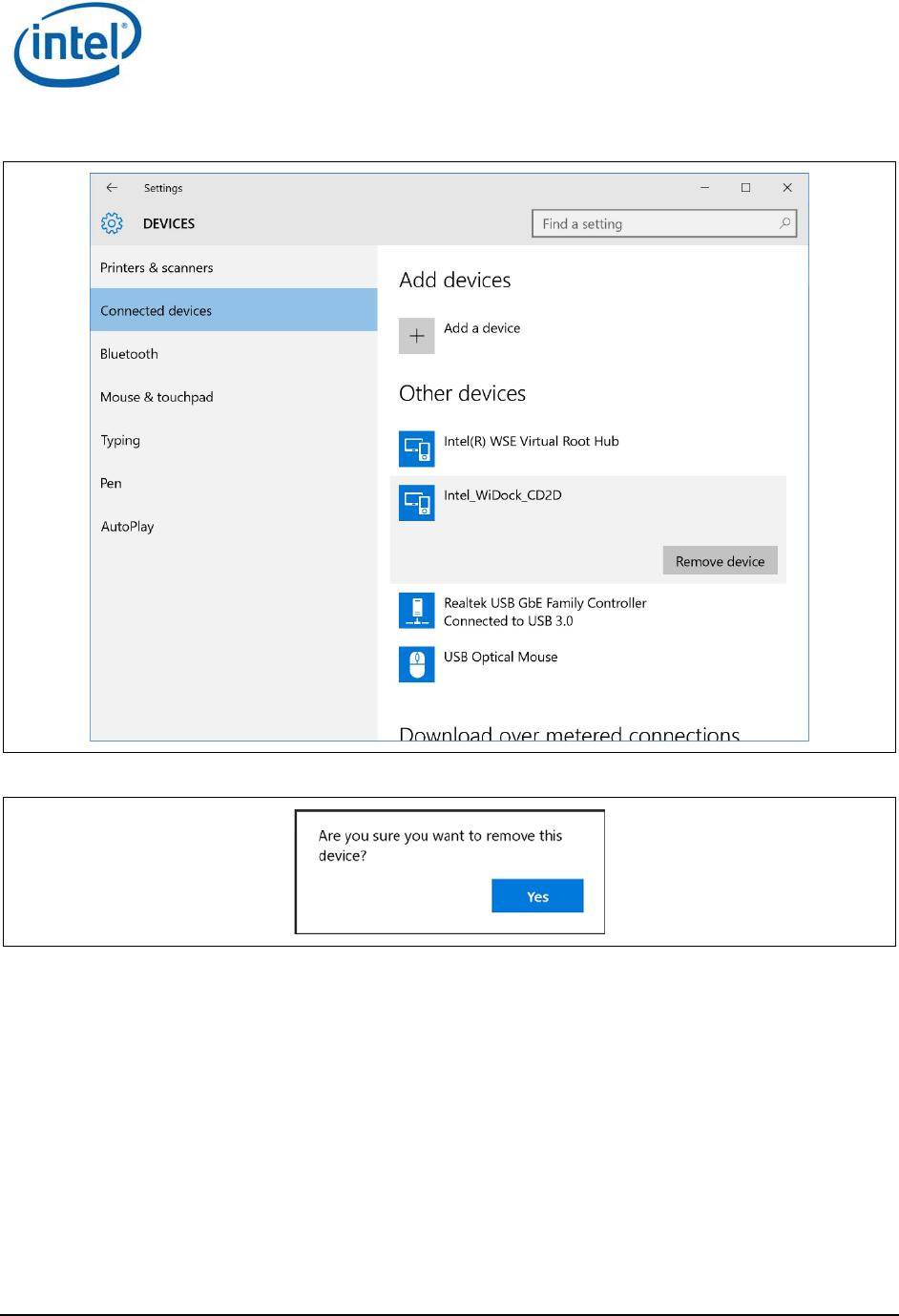
4.5 Managing docks
User may delete docks he has previously connected to.
1. To delete docks go to Connected devices (Settings ->Devices -> Connected devices), click on
the dock you want to remove and then press the Remove device button, as shown in 4-13 and
then approve it as shown in Figure 4-13.
WiGig Application User Manual for Windows 10*
Intel
®
Wireless Gigabit v2.0
October 2015 User Guide
Document Number: 537178-3.3 Intel Confidential 41
Figure 4-13 Remove device
Figure 4-14 Remove Device approval
WiGig Application User Manual for Windows 10*
Intel
®
Wireless Gigabit v2.0
User Guide October 2015
42 Intel Confidential Document Number: 537178-3.3
4.6 Notification messages
There are notification messages that inform user about the different application activities, like possible
limitations or errors.
4.6.1 Not found
In case no device can be found the Connect pane will return with a request to verify that the RF is on.
See Figure 4-15.
Figure 4-15 Device not found
WiGig Application User Manual for Windows 10*
Intel
®
Wireless Gigabit v2.0
October 2015 User Guide
Document Number: 537178-3.3 Intel Confidential 43
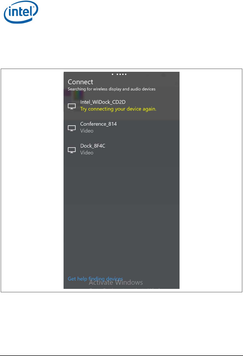
4.6.2 Try Connecting your device again
In case there was a problem in the pairing flow (before the user has the dock profile) the Connect
pane will return with an error Try connecting your device again Figure 4-16.
Figure 4-16 Try connecting your device again
WiGig Application User Manual for Windows 10*
Intel
®
Wireless Gigabit v2.0
User Guide October 2015
44 Intel Confidential Document Number: 537178-3.3
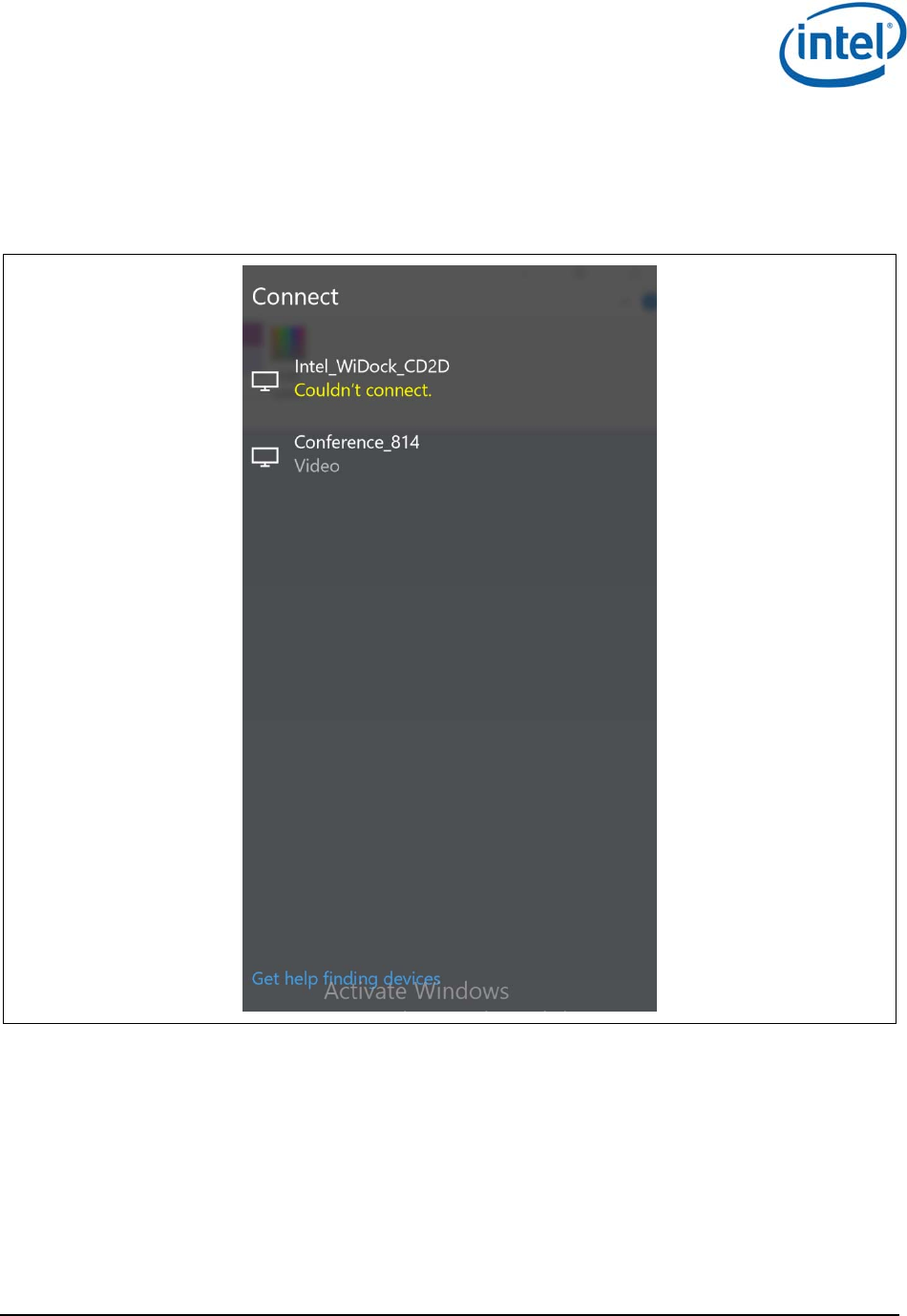
4.6.3 Couldn’t connect
In case there was a problem in the connecting flow (after the user has the dock profile) the Connect
pane will return with an error Couldn’t connect Figure 4-17.
Figure 4-17 Couldn’t connect
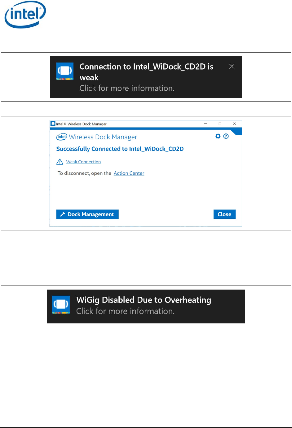
4.6.4 Weak connection
The weak connection toast is displayed if the connection is weak but connected, as shown in Figure
4-18. In addition in case the Intel
®
Wireless Dock Manager application is open it will notify the user
about this state as describe in Figure 4-19.
WiGig Application User Manual for Windows 10*
Intel
®
Wireless Gigabit v2.0
October 2015 User Guide
Document Number: 537178-3.3 Intel Confidential 45
Figure 4-18 Weak connection toast
Figure 4-19 Weak connection screen
4.6.5 WiGig disabled – critical temperature
In case the WiGig is disabled due to overheating, toast will be popup Figure 4-20. In addition in case
the Intel
®
Wireless Dock Manager application is open it will notify the user about this state as describe
in Figure 4-21.
Figure 4-20 WiGig disabled due to overheating toast
WiGig Application User Manual for Windows 10*
Intel
®
Wireless Gigabit v2.0
User Guide October 2015
46 Intel Confidential Document Number: 537178-3.3
Figure 4-21 WiGig disabled due to overheating screen
§

The Wireless Dock and Multiple Displays
Intel
®
Wireless Gigabit v2.0
October 2015 User Guide
Document Number: 537178-3.3 Intel Confidential 47
5 The Wireless Dock and Multiple
Displays
5.1 Intel
®
WiGig A/V wireless capabilities
Intel
®
WiGig is seen by the Intel
®
Display Driver as a DP V1.2 Branch device. It advertises its
capabilities to the driver using standard DisplayPort V1.2a tools.
The capabilities include A/V bandwidth, as well as other capabilities related to the internal A/V
subsystem.
Intel
®
WiGig HW can support up to two A/V streams. This limitation is advertised to the Intel
DisplayPort Driver, which then limits the number of active streams sent over the Intel
®
WiGig DP
interface.
When the user connects three displays to the MST hub at the output of the Intel
®
WiGig-based dock,
only two out of the three displays connected can be active at the same time.
5.1.1 Intel
®
WiGig DisplayPort Bandwidth and other limitations
The DisplayPort V1.2a standard defines mechanisms that allow branch devices to advertise their
capabilities and limitations to the Display Driver. There are two main limitations which may affect the
user experience:
1. DisplayPort Bandwidth (AKA PBN): Intel
®
WiGig DP interface operates at 4 2.7 gbps
speed. This results in an ability to support single display resolutions of up to 2560x1600@60 Hz
or Dual Display Resolutions of 19201200@60 Hz.
For example, if the user connects 2 1600p60 capable displays to the dock, it cannot drive the
native resolution to both displays due to the DP BW limitation. The Display Driver will remove
some of the video modes from one of the displays while allowing native resolution to the 2
nd
display.
2. Wireless Branch Device Limitations (AKA CCS): Intel
®
WiGig DP interface advertises
Wireless Branch Device limitations related to the capabilities of the integrated video Encoders
and Decoders.
Currently the advertised limitations are:
a. Frame Width <= 2560
b. Frame Height <= 1600
c. Max Frame Rate = 60 Hz
d. Min Frame Rate = 59 Hz
e. Max Pixel Clock = 268 MHz
f. RGB: Only color space modes supported
g. Progressive only modes supported
All display modes not meeting the criteria above will be removed by the display driver and
not shown by the Resolution Manager.
The Wireless Dock and Multiple Displays
Intel
®
Wireless Gigabit v2.0
User Guide October 2015
48 Intel Confidential Document Number: 537178-3.3
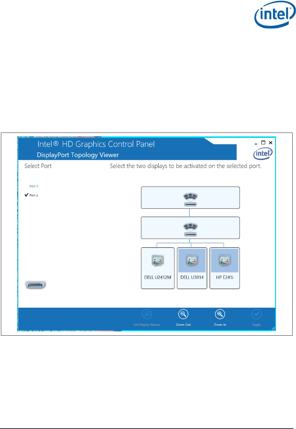
5.2 User experience when connecting more than two
displays to the wireless dock
The driver initially selects two default displays. These will be the displays connected to the output
ports #1 and #2 of the MST hub device. The display connected to port #3 will not be used and will not
be seen on the OS resolution manager.
The Intel
®
Display Driver generates a popup window stating: DisplayPort Topology Notification. A new
DisplayPort Topology has been identified. Click the popup to open the Intel
®
HD Graphics control
panel’s DisplayPort Topology Viewer (see Figure 5-1). The user is requested to select the two displays
to be activated for the Intel
®
WiGig selected port. Selected displays are marked in light-blue.
Figure 5-1 DisplayPort topology viewer
Once the user selects the active displays the display driver will re-initiate the A/V link setup process
and activate the selected displays.
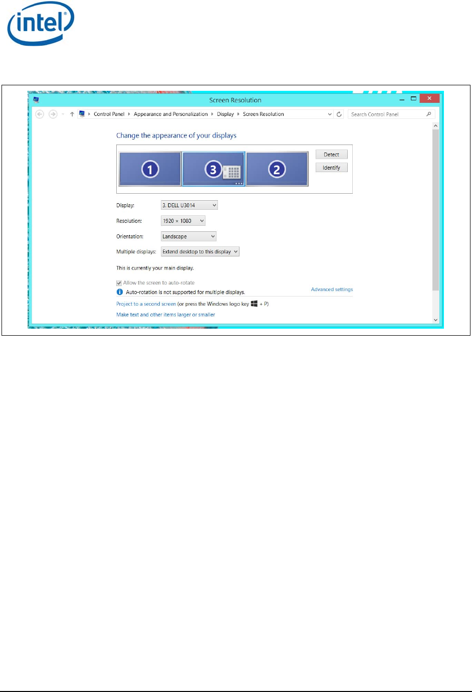
Only the selected displays will be seen on Windows Screen Resolution Manager. The unselected
display will not be shown (see Figure 5-2). The user can select the operating mode (duplicate/extend),
activate and deactivate the screens using the Windows Screen Resolution Manager.
The Wireless Dock and Multiple Displays
Intel
®
Wireless Gigabit v2.0
October 2015 User Guide
Document Number: 537178-3.3 Intel Confidential 49
Figure 5-2 Windows screen resolution manager
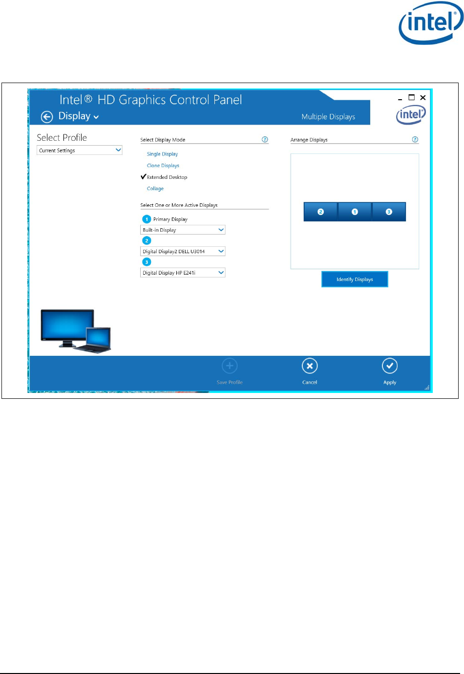
The same behavior occurs when the user uses the Intel
®
Graphics Control Panel Display tab (see
Figure 5-3). On this screen only the two displays selected in the Topology Manager will be seen.
The Wireless Dock and Multiple Displays
Intel
®
Wireless Gigabit v2.0
User Guide October 2015
50 Intel Confidential Document Number: 537178-3.3
Figure 5-3 Graphics control panel
§

Intel® WiFi Adapter Information Guide
index.htm[7/3/2014 12:04:57 PM]
Intel® WiFi Adapter Information Guide
This version of Intel® PROSet/Wireless WiFi Software is compatible with the adapters listed below. However, note
that newer features provided in this software release are generally not supported for older, legacy adapters.
The following adapters are supported on this release for Windows* 8 and Windows* 8.1 with Windows* 7 drivers
from Intel®:
Intel® Centrino® Wireless-N 100
Intel® Centrino® Wireless-N 130
Intel® Centrino® Wireless-N 1000
Intel® Centrino® Wireless-N 1030
Intel® Centrino® Advanced-N 6200
Intel® Centrino® Advanced-N 6230
The following adapters are supported on this release for Windows* 8 with Windows* 8 drivers from Intel®:
Intel® Centrino® Wireless-N 105
Intel® Centrino® Wireless-N 135
Intel® Centrino® Wireless-N 2200
Intel® Centrino® Wireless-N 2230
Intel® Centrino® Wireless-N + WiMAX 6150
Intel® Centrino® Advanced-N 6205
Intel® Centrino® Advanced-N 6235
Intel® Centrino® Advanced-N + WiMAX 6250
Intel® Centrino® Ultimate-N 6300
Intel® Dual Band Wireless-AC 7260
Intel® Dual Band Wireless-N 7260
Intel® Wireless-N 7260
Intel® Dual Band Wireless-AC 3160
Intel® Dual Band Wireless-AC 7265
Intel® Dual Band Wireless-N 7265
Intel® Wireless-N 7265
The following adapters are supported on this release for Windows* 8.1 with Windows* 8 drivers from Intel®:
Intel® Centrino® Wireless-N 105
Intel® Centrino® Wireless-N 135
Intel® Centrino® Wireless-N 2200
Intel® Centrino® Wireless-N 2230
Intel® Centrino® Wireless-N + WiMAX 6150
Intel® Centrino® Advanced-N 6205
Intel® Centrino® Advanced-N 6235
Intel® Centrino® Advanced-N + WiMAX 6250
Intel® Centrino® Ultimate-N 6300
The following adapters are supported on this release for Windows* 8.1 with Windows* 8.1 drivers from Intel®:
Intel® Dual Band Wireless-AC 7260
Intel® Dual Band Wireless-N 7260
Intel® Wireless-N 7260
Intel® Dual Band Wireless-AC 3160
Intel® Dual Band Wireless-AC 7265
Intel® Dual Band Wireless-N 7265
Intel® Wireless-N 7265
With your WiFi network card, you can access WiFi networks, share files or printers, or even share your Internet
connection. All of these features can be explored using a WiFi network in your home or office. This WiFi network
solution is designed for both home and business use. Additional users and features can be added as your networking
needs grow and change.
● Intel® Tri-Band Wireless-AC 18260
● Intel® Tri-Band Wireless-AC 18260

Intel® WiFi Adapter Information Guide
index.htm[7/3/2014 12:04:57 PM]
This guide contains basic information about Intel adapters. It includes information about several adapter properties
that you can set to control and enhance the performance of your adapter with your particular wireless network and
environment. Intel® wireless adapters enable fast connectivity without wires for desktop and notebook PCs.
Adapter Settings
Regulatory Information
Specifications
Important Information
Support
Warranty
Glossary
Depending on the model of your Intel WiFi adapter, your adapter is compatible with 802.11a, 802.11b, 802.11g, and
802.11n (draft 2.0) wireless standards. Operating at 5GHz or 2.4GHz frequency at data rates of up to 450 Mbps,
you can now connect your computer to existing high-speed networks that use multiple access points within large or
small environments. Your WiFi adapter maintains automatic data rate control according to the access point location
and signal strength to achieve the fastest possible connection. All of your wireless network connections are easily
managed by the WiFi connection utility. Profiles that are set up through the WiFi connection utility provide enhanced
security measures with 802.1X network authentication.
Information in this document is subject to change without notice.
© 2004–2014 Intel Corporation. All rights reserved. Intel Corporation, 5200 N.E. Elam Young Parkway,
Hillsboro, OR 97124-6497 USA
The copying or reproducing of any material in this document in any manner whatsoever without the written
permission of Intel Corporation is strictly forbidden. Intel® is a trademark or registered trademark of Intel
Corporation or its subsidiaries in the United States and other countries. Other trademarks and trade names may be
used in this document to refer to either the entities claiming the marks and names or their products. Intel disclaims
any proprietary interest in trademarks and trade names other than its own. Microsoft and Windows are registered
trademarks of Microsoft Corporation. Windows Vista is either a registered trademark or trademark of Microsoft
Corporation in the United States and/or other countries.
*Other names and brands may be claimed as the property of others.
Intel Corporation assumes no responsibility for errors or omissions in this document. Nor does Intel make any
commitment to update the information contained herein.
"IMPORTANT NOTICE FOR ALL USERS OR DISTRIBUTORS:
Intel wireless LAN adapters are engineered, manufactured, tested, and quality checked to ensure that they meet all
necessary local and governmental regulatory agency requirements for the regions that they are designated and/or
marked to ship into. Because wireless LANs are generally unlicensed devices that share spectrum with radars,
satellites, and other licensed and unlicensed devices, it is sometimes necessary to dynamically detect, avoid, and
limit usage to avoid interference with these devices. In many instances Intel is required to provide test data to prove
regional and local compliance to regional and governmental regulations before certification or approval to use the
product is granted. Intel's wireless LAN's EEPROM, firmware, and software driver are designed to carefully control
parameters that affect radio operation and to ensure electromagnetic compliance (EMC). These parameters include,
without limitation, RF power, spectrum usage, channel scanning, and human exposure.
For these reasons Intel cannot permit any manipulation by third parties of the software provided in binary format
with the wireless LAN adapters (e.g., the EEPROM and firmware). Furthermore, if you use any patches, utilities, or
code with the Intel wireless LAN adapters that have been manipulated by an unauthorized party (i.e., patches,
utilities, or code (including open source code modifications) which have not been validated by Intel), (i) you will be
solely responsible for ensuring the regulatory compliance of the products, (ii) Intel will bear no liability, under any
theory of liability for any issues associated with the modified products, including without limitation, claims under the
warranty and/or issues arising from regulatory non-compliance, and (iii) Intel will not provide or be required to
assist in providing support to any third parties for such modified products.
Note: Many regulatory agencies consider Wireless LAN adapters to be "modules", and accordingly, condition system-
level regulatory approval upon receipt and review of test data documenting that the antennas and system

Intel® WiFi Adapter Information Guide
index.htm[7/3/2014 12:04:57 PM]
configuration do not cause the EMC and radio operation to be non-compliant."
January 7, 2014

Adapter Settings
adaptusr.htm[7/3/2014 12:04:59 PM]
Back to Contents
Adapter Settings
The Advanced tab displays the device properties for the WiFi adapter installed on your computer.
How to Access
At the Intel® PROSet/Wireless WiFi Connection Utility, Advanced Menu click Adapter Settings. Select the
Advanced tab.
WiFi Adapter Settings Description
Name Description
802.11ac Mode
(5GHz)
The 802.11ac standard builds on 802.11n standard. 802.11ac Mode delivers up to 867Mbps
(theoretical) by increasing channel bandwidth to 80MHz and adding higher density modulation
(256 QAM). Select Enabled or Disabled to set the 802.11ac mode of the WiFi adapter. Enabled
is the default setting. This setting applies to 802.11ac capable adapters only.
802.11n
Channel Width
(2.4 GHz)
Set high throughput channel width to maximize performance. Set the channel width to Auto or
20MHz. Use 20MHz if 802.11n channels are restricted. This setting applies to 802.11n capable
adapters only.
NOTE: This setting does not apply to the Intel® Wireless WiFi Link 4965AGN (uses 20 MHz
channel width only).
802.11n
Channel Width
(5.2 GHz)
Set high throughput channel width to maximize performance. Set the channel width to Auto or
20MHz. Use 20MHz if 802.11n channels are restricted. This setting applies to 802.11n capable
adapters only.
NOTE: This setting does not apply to the following adapters:
Intel® WiFi Link 1000
Intel® Wireless WiFi Link 4965AGN
802.11n Mode The 802.11n standard builds on previous 802.11 standards by adding multiple-input multiple-
output (MIMO). MIMO increases data throughput to improve transfer rate. Select Enabled or
Disabled to set the 802.11n mode of the WiFi adapter. Enabled is the default setting. This
setting applies to 802.11n capable adapters only.
NOTE: To achieve transfer rates greater than 54 Mbps on 802.11n connections, WPA2*-AES
security must be selected. No security (None) can be selected to enable network setup and
troubleshooting.
An administrator can enable or disable support for high throughput mode to reduce power-
consumption or conflicts with other bands or compatibility issues.
Ad Hoc
Channel
802.11b/g
Select Enabled or Disabled.
Ad Hoc QoS
Mode Quality of Service (QoS) control in ad hoc networks. QoS provides prioritization of traffic from the
access point over a wireless LAN based on traffic classification. WMM (Wi-Fi Multimedia) is the
QoS certification of the Wi-Fi Alliance (WFA). When WMM is enabled, the WiFi adapter uses WMM
to support priority tagging and queuing capabilities for Wi-Fi networks.
WMM Enabled (Default)
WMM Disabled
Bluetooth® Enable or disable Bluetooth® AMP. AMP stands for alternate MAC/PHY and uses the 802.11 (Wi-

Adapter Settings
adaptusr.htm[7/3/2014 12:04:59 PM]
AMP Fi) as the high-speed transport. If disabled, Bluetooth HS is turned off.
HT Mode/VHT
Mode/Disabled This settings lets you select HT Mode (High Throughput mode), VHT Mode (Very High Throughput
Mode) or to disable both modes. HT Mode supports 802.11n compatibility, whereas VHT Mode
supports 802.11ac compatibility.
Fat Channel
Intolerant This setting communicates to access points that this WiFi adapter does not prefer 40MHz
channels in the 2.4GHz band. The default setting is for this to be turned off (disabled), so that
the adapter does not send this notification. If the access point continues to use 40MHz channels,
the WiFi adapter will also use 40MHz channels if the 802.11n Channel Width (2.4GHz) setting is
AUTO.
NOTE: This setting does not apply to the following adapters:
Intel® Wireless WiFi Link 4965AG_
Intel® PRO/Wireless 3945ABG Network Connection
Mixed mode
protection Use to avoid data collisions in a mixed 802.11b and 802.11g environment. Request to
Send/Clear to Send (RTS/CTS) should be used in an environment where clients may not hear
each other. CTS-to-self can be used to gain more throughput in an environment where clients
are in close proximity and can hear each other.
Preferred Band In an environment with other radiating devices nearby (such as microwave ovens, cordless
telephones, access points, or client devices), in order to reduce interference you may want
prefer the 5GHz band over the 2.4GHz band, or vice-versa. Your choices are:
No Preference
Prefer 2.4GHz band
Prefer 5GHz band
Here are the various Wi-Fi bands:
802.11 legacy - 2.4GHz
802.11a - 3.7GHz and 5GHz
802.11b - 2.4GHz
802.11g - 2.4GHz
802.11n - 2.4GHz and 5GHz
802.11ac - 5GHz
Roaming
AggressivenessThis setting lets you define how aggressively your wireless client roams to improve connection to
an access point. There are five available settings.
3. Medium: This is the default. A balanced setting between not roaming and performance.
1. Lowest: Your wireless client will not roam. Only significant link quality degradation
causes it to roam to another access point.
5. Highest: Your wireless client continuously tracks the link quality. If any degradation
occurs, it tries to find and roam to a better access point.
Transmit
Power Default Setting: Highest power setting.
Lowest: Minimum Coverage: Set the adapter to the lowest transmit power. Enables you to
expand the number of coverage areas or confine a coverage area. Reduces the coverage area in
high traffic areas to improve overall transmission quality and avoids congestion and interference
with other devices.
Highest: Maximum Coverage: Set the adapter to a maximum transmit power level. Select for
maximum performance and range in environments with limited additional WiFi radio devices.
NOTE: The optimal setting is for a user to always set the transmit power at the lowest possible
level that is still compatible with the quality of their communication. This allows the maximum
number of wireless devices to operate in dense areas and reduce interference with other devices
that it shares the same radio spectrum with.
NOTE: This setting takes effect when either Network (Infrastructure) or Device to Device (ad

Adapter Settings
adaptusr.htm[7/3/2014 12:04:59 PM]
hoc) mode is used.
Wake on Magic
Packet This setting, enabled, wakes the computer from a sleep state when it receives a "magic packet"
from a sending computer. The magic packet contains the MAC address of the intended
destination computer.
Enabling turns on Wake on Magic Packet. Disabling turns off Wake on Magic Packet. Disabling
this only disables the magic packet feature, not Wake on Wireless LAN.
Wake on
Pattern Match This feature wakes the computer from a sleep state when a particular wake pattern is received at
the adapter. This feature is supported by the Window* 7 and Windows 8. Such patterns typically
are:
Wake on new incoming TCP connection for IPv4 and IPv6 (TCP SYN IPv4 and TCP SYN
IPv6).
Wake on 802.1x re-authentication packets.
Disabling this only disables the pattern match feature, not Wake on Wireless LAN.
Wireless Mode Select which mode to use for connection to a wireless network:
802.11a only: Connect the wireless WiFi adapter to 802.11a networks only. Not
applicable for all adapters.
802.11b only: Connect the wireless WiFi adapter to 802.11b networks only. Not
applicable for all adapters.
802.11g only: Connect the wireless WiFi adapter to 802.11g networks only.
802.11a and 802.11g: Connect the WiFi adapter to 802.11a and 802.11g networks only.
Not applicable for all adapters.
802.11b and 802.11g: Connect the WiFi adapter to 802.11b and 802.11g networks only.
Not applicable for all adapters.
802.11a, 802.11b, and 802.11g: (Default) - Connect to either 802.11a, 802.11b or
802.11g wireless networks. Not applicable for all adapters.
OK Saves settings and returns to the previous page.
Cancel Closes and cancels any changes.
Back to Top
Back to Contents
Trademarks and Disclaimers

Regulatory Information
regs.htm[7/3/2014 12:04:59 PM]
Back to Contents
Regulatory Information
This section provides regulatory information for the following wireless adapters:
Intel® Centrino® Wireless-N 100
Intel® Centrino® Wireless-N 105
Intel® Centrino® Wireless-N 130
Intel® Centrino® Wireless-N 135
Intel® Centrino® Wireless-N 1000
Intel® Centrino® Wireless-N 1030
Intel® Centrino® Wireless-N 2200
Intel® Centrino® Wireless-N 2230
Intel® Centrino® Wireless-N + WiMAX 6150
Intel® Centrino® Advanced-N 6200
Intel® Centrino® Advanced-N 6205
Intel® Centrino® Advanced-N 6230
Intel® Centrino® Advanced-N 6235
Intel® Centrino® Advanced-N + WiMAX 6250
Intel® Centrino® Ultimate-N 6300
Intel® Dual Band Wireless-AC 7260
Intel® Dual Band Wireless-N 7260
Intel® Wireless-N 7260
Intel® Dual Band Wireless-AC 3160
Intel® Dual Band Wireless-AC 7265
Intel® Dual Band Wireless-N 7265
Intel® Wireless-N 7265
NOTE: Due to the evolving state of regulations and standards in the wireless LAN field (IEEE 802.11 and
similar standards), the information provided herein is subject to change. Intel Corporation assumes no
responsibility for errors or omissions in this document.
Intel WiFi/WiMAX Wireless Adapters
Information in this section supports the following wireless adapters:
Intel® Centrino® Wireless-N + WiMAX 6150
Intel® Centrino® Advanced-N + WiMAX 6250
See Specifications for complete wireless adapter specifications.
NOTE: In this section, all references to the "wireless adapter" refer to all adapters listed above.
The following information is provided:
Information for the User
Regulatory Information
Information for OEMs and Host Integrators
INFORMATION FOR THE USER
Safety Notices
USA FCC Radio Frequency Exposure
The FCC with its action in ET Docket 96-8 has adopted a safety standard for human exposure to radio frequency (RF)
electromagnetic energy emitted by FCC certified equipment. The wireless adapter meets the Human Exposure limits
● Intel® Tri-Band Wireless-AC 18260

Regulatory Information
regs.htm[7/3/2014 12:04:59 PM]
found in OET Bulletin 65, supplement C, 2001, and ANSI/IEEE C95.1, 1992. Proper operation of this radio according
to the instructions found in this manual will result in exposure substantially below the FCC’s recommended limits.
The following safety precautions should be observed:
Do not touch or move antenna while the unit is transmitting or receiving.
Do not hold any component containing the radio such that the antenna is very close or touching any exposed
parts of the body, especially the face or eyes, while transmitting.
Do not operate the radio or attempt to transmit data unless the antenna is connected; this behavior may cause
damage to the radio.
Use in specific environments:
The use of wireless adapters in hazardous locations is limited by the constraints posed by the safety
directors of such environments.
The use of electronic devices equipped with wireless adapters on airplanes is governed by rules for each
commercial airline operator.
The use of wireless adapters in hospitals is restricted to the limits set forth by each hospital.
Explosive Device Proximity Warning
Warning: Do not operate a portable transmitter (including this wireless adapter) near unshielded blasting caps
or in an explosive environment unless the transmitter has been modified to be qualified for such use.
Antenna Warnings
Warning: The wireless adapter is not designed for use with high-gain directional antennas.
Use On Aircraft Caution
Caution: Regulations of commercial airline operators may prohibit airborne operation of certain electronic
devices equipped with radio-frequency wireless devices (wireless adapters) because their signals could interfere with
critical aircraft instruments.
Other Wireless Devices
Safety Notices for Other Devices in the Wireless Network: See the documentation supplied with wireless
adapters or other devices in the wireless network.
Local Restrictions on 802.11a, 802.11b, 802.11g, 802.11n, and 802.16e Radio Usage
Caution: Due to the fact that the frequencies used by 802.11a, 802.11b, 802.11g, 802.11n, and 802.16e
wireless LAN devices may not yet be harmonized in all countries, 802.11a, 802.11b, 802.11g, 802.11n, and 802.16e
products are designed for use only in specific countries, and are not allowed to be operated in countries other than
those of designated use. As a user of these products, you are responsible for ensuring that the products are used
only in the countries for which they were intended and for verifying that they are configured with the correct
selection of frequency and channel for the country of use. The device transmit power control (TPC) interface is part
of the Intel® PROSet/Wireless WiFi Connection Utility Software. Operational restrictions for Equivalent Isotropic
Radiated Power (EIRP) are provided by the system manufacturer. Any deviation from the permissible power and
frequency settings for the country of use is an infringement of national law and may be punished as such.
Wireless Interoperability
The wireless adapter is designed to be interoperable with other wireless LAN products that are based on direct
sequence spread spectrum (DSSS) radio technology and to comply with the following standards:
IEEE Std. 802.11b compliant Standard on Wireless LAN
IEEE Std. 802.11g compliant Standard on Wireless LAN
IEEE Std. 802.11a compliant Standard on Wireless LAN
IEEE Std. 802.11n draft 2.0 compliant on Wireless LAN

Regulatory Information
regs.htm[7/3/2014 12:04:59 PM]
IEEE 802.16e-2005 Wave 2 compliant
Wireless Fidelity certification, as defined by the Wi-Fi Alliance
WiMAX certification as defined by the WiMAX Forum
The Wireless Adapter and Your Health
The wireless adapter, like other radio devices, emits radio frequency electromagnetic energy. The level of energy
emitted by the wireless adapter, however, is less than the electromagnetic energy emitted by other wireless devices
such as mobile phones. The wireless adapter operates within the guidelines found in radio frequency safety
standards and recommendations. These standards and recommendations reflect the consensus of the scientific
community and result from deliberations of panels and committees of scientists who continually review and interpret
the extensive research literature. In some situations or environments, the use of the wireless adapter may be
restricted by the proprietor of the building or responsible representatives of the applicable organization. Examples of
such situations may include:
Using the wireless adapter on board airplanes, or
Using the wireless adapter in any other environment where the risk of interference with other devices or
services is perceived or identified as being harmful.
If you are uncertain of the policy that applies to the use of wireless adapters in a specific organization or
environment (an airport, for example), you are encouraged to ask for authorization to use the adapter before you
turn it on.
REGULATORY INFORMATION
USA - Federal Communications Commission (FCC)
This wireless adapter is restricted to indoor use due to its operation in the 5.15 to 5.25 and 5.470 to 5.75GHz
frequency ranges. FCC requires this wireless adapter to be used indoors for the frequency ranges 5.15 to 5.25GHz
and 5.470 to 5.75GHz to reduce the potential for harmful interference to co-channel mobile satellite systems. No
configuration controls are provided for Intel® wireless adapters allowing any change in the frequency of operations
outside the FCC grant of authorization for U.S. operation according to Part 15.407 of the FCC rules.
Intel® wireless adapters are intended for OEM integrators only.
Intel® wireless adapters cannot be co-located with any other transmitter unless approved by the FCC.
This wireless adapter complies with Part 15 of the FCC Rules. Operation of the device is subject to the following two
conditions:
This device may not cause harmful interference.
This device must accept any interference that may cause undesired operation.
Class B Device Interference Statement
This wireless adapter has been tested and found to comply with the limits for a Class B digital device, pursuant to
Part 15 of the FCC Rules. These limits are designed to provide reasonable protection against harmful interference in
a residential installation. This wireless adapter generates, uses, and can radiate radio frequency energy. If the
wireless adapter is not installed and used in accordance with the instructions, the wireless adapter may cause
harmful interference to radio communications. There is no guarantee, however, that such interference will not occur
in a particular installation. If this wireless adapter does cause harmful interference to radio or television reception
(which can be determined by turning the equipment off and on), the user is encouraged to try to correct the
interference by taking one or more of the following measures:
Reorient or relocate the receiving antenna of the equipment experiencing the interference.
Increase the distance between the wireless adapter and the equipment experiencing the interference.
Connect the computer with the wireless adapter to an outlet on a circuit different from that to which the
equipment experiencing the interference is connected.
Consult the dealer or an experienced radio/TV technician for help.
NOTE: The adapter must be installed and used in strict accordance with the manufacturer's instructions

Regulatory Information
regs.htm[7/3/2014 12:04:59 PM]
as described in the user documentation that comes with the product. Any other installation or use will
violate FCC Part 15 regulations.
Safety Approval Considerations
This device has been safety approved as a component and is for use only in complete equipment where the
acceptability of the combination is determined by the appropriate safety agencies. When installed, consideration
must be given to the following:
It must be installed into a compliant host device meeting the requirement of UL/EN/IEC 60950-1 2nd edition
including the general provisions of enclosure design 1.6.2 and specifically paragraph 1.2.6.2 (Fire Enclosure).
The device shall be supplied by a SELV source when installed in the end-use equipment.
A heating test shall be considered in the end-use product for meeting the requirement of UL/EN/IEC 60950-1
2nd edition.
Low Halogen
Applies only to brominated and chlorinated flame retardants (BFRs/CFRs) and PVC in the final product. Intel
components as well as purchased components on the finished assembly meet JS-709 requirements, and the PCB /
substrate meet IEC 61249-2-21 requirements. The replacement of halogenated flame retardants and/or PVC may
not be better for the environment.
Japan
5GHz 帯は室内でのみ使用のこと
Korea
해당 무선설비는 전파혼신 가능성이 있으므로 인명안전과 관련된 서비스는 할 수 없음.
해당 무선 설비는 5150-5250MHz 대역에서 실내에서만 사용할 수 있음.
Mexico
La operación de este equipo está sujeta a las siguientes dos condiciones: (1) es posible que este equipo o dispositivo
no cause interferencia perjudicial y (2) este equipo o dispositivo debe aceptar cualquier interferencia, incluyendo la
que pueda causar su operación no deseada.
Taiwan

Regulatory Information
regs.htm[7/3/2014 12:04:59 PM]
在5.25-5.35 秭赫頻帶內操作之無線資訊傳輸設備 限於室內使用。
Radio Approvals
To determine whether you are allowed to use your wireless network device in a specific country, please check to see
if the radio type number that is printed on the identification label of your device is listed in the manufacturer's OEM
Regulatory Guidance document.
Modular Regulatory Certification Country Markings
A list of countries requiring regulatory markings is available. Note that the lists include only countries requiring
marking but not all certified countries. To find the regulatory country marking information for your adapter, perform
these steps:
1. Open this web site: http://www.intel.com/support/wireless/wlan/
2. Click on the link for your adapter.
3. Click Document and Guides.
4. Under Regulatory Information, click Regulatory documents for your adapter.
Regulatory ID
USA: Model 7265D2W, FCC ID: PD97265D2
Canada: Model 7265D2W, IC: 1000M-7265D2
INFORMATION FOR OEMs and HOST INTEGRATORS
The guidelines described within this document are provided to OEM integrators installing Intel® wireless adapters in
notebook and tablet PC host platforms. Adherence to these requirements is necessary to meet the conditions of
compliance with FCC rules, including RF exposure. When all antenna type and placement guidelines described herein
are fulfilled the Intel® wireless adapters may be incorporated into notebook and tablet PC host platforms with no
further restrictions. If any of the guidelines described herein are not satisfied it may be necessary for the OEM or
integrator to perform additional testing and/or obtain additional approval. The OEM or integrator is responsible to
determine the required host regulatory testing and/or obtaining the required host approvals for compliance.
Intel® wireless adapters are intended for OEMs and host integrators only.
The Intel® wireless adapter FCC Grant of Authorization describes any limited conditions of modular approval.
The Intel® wireless adapters must be operated with an access point that has been approved for the country of
operation.
Changes or modification to Intel® wireless adapters by OEMs, integrators or other third parties is not
Model 7265D2W &7265D2W AN, IC: 1000M-7265D2

Regulatory Information
regs.htm[7/3/2014 12:04:59 PM]
permitted. Any changes or modification to Intel® wireless adapters by OEMs, integrators or other third parties
will void authorization to operate the adapter.
Antenna Type and Gains
Only antennas of the same type and with equal or less gains as shown below may be used with the Intel® wireless
adapters. Other types of antennas and/or higher gain antennas may require additional authorization for operation.
Antenna
Type Antenna
Location
(Main/Aux
2.4GHz
Peak Gain
in dBi*
2.6GHz
Peak Gain
in dBi*
5.2GHz
Peak Gain
in dBi*
5.5GHz
Peak Gain
in dBi*
5.7GHz
Peak Gain
in dBi*
PIFA Main
Aux 3.24 3.47 3.73 4.77 4.77
MIMO
*All antenna gains include cable loss.
Antenna Placement Within the Host Platform
To ensure RF exposure compliance the antenna(s) used with the Intel® wireless adapters must be installed in
notebook or tablet PC host platforms to provide a minimum separation distance from all persons, in all operating
modes and orientations of the host platform, with strict adherence to the table below. The antenna separation
distance applies to both horizontal and vertical orientation of the antenna when installed in the host system.
Intel® Wireless Adapter Minimum required antenna-to-user
separation distance
Intel® Centrino® Wireless-N + WiMAX 6150 18 mm
Intel® Centrino® Wireless-N + WiMAX 6350 17 mm
Simultaneous Transmission of Intel® Wireless Adapters with Other Integrated or
Plug-In Transmitters
Based upon FCC Knowledge Database publication number 616217 D03 Supplement
https://apps.fcc.gov/oetcf/kdb/forms/FTSSearchResultPage.cfm?id=33240&switch=P, when there are multiple
transmitting devices installed in a host device, an RF exposure transmitting assessment shall be performed to
determine the necessary application and test requirements. OEM integrators must identify all possible combinations
of simultaneous transmission configurations for all transmitters and antennas installed in the host system. This
includes transmitters installed in the host as mobile devices (>20 cm separation from user) and portable devices
(<20 cm separation from user). OEM integrators should consult the actual FCC KDB 616217 D03 Supplement
document for all details in making this assessment to determine if any additional requirements for testing or FCC
approval is necessary.
Information To Be Supplied to the End User by the OEM or Integrator
The following regulatory and safety notices must be published in documentation supplied to the end user of the
product or system incorporating the Intel® wireless adapter, in compliance with local regulations. Host system must
be labeled with "Contains FCC ID: XXXXXXXX", FCC ID displayed on label.
The Intel® wireless adapter must be installed and used in strict accordance with the manufacturer's instructions as
described in the user documentation that comes with the product. Intel Corporation is not responsible for any radio
or television interference caused by unauthorized modification of the devices included with the wireless adapter kit
or the substitution or attachment of connecting cables and equipment other than that specified by Intel Corporation.
The correction of interference caused by such unauthorized modification, substitution or attachment is the
responsibility of the user. Intel Corporation and authorized resellers or distributors are not liable for any damage or

Regulatory Information
regs.htm[7/3/2014 12:04:59 PM]
violation of government regulations that may arise from the user failing to comply with these guidelines.
Local Restriction of 802.11a, 802.11b, 802.11g, 802.11n, and 802.11e Radio Usage
The following statement on local restrictions must be published as part of the compliance documentation for all
802.11a, 802.11b, 802.11g and 802.11n products.
Caution: Due to the fact that the frequencies used by 802.11a, 802.11b, 802.11g, 802.11n, and 802.16e
wireless LAN devices may not yet be harmonized in all countries, 802.11a, 802.11b, 802.11g, 802.11n, and 802.16e
products are designed for use only in specific countries, and are not allowed to be operated in countries other than
those of designated use. As a user of these products, you are responsible for ensuring that the products are used
only in the countries for which they were intended and for verifying that they are configured with the correct
selection of frequency and channel for the country of use. Any deviation from the permissible power and frequency
settings for the country of use is an infringement of national law and may be punished as such.
Intel WiFi Adapters, 802.11n Compliant
The information in this section applies to the following products:
Intel® Centrino® Wireless-N 100
Intel® Centrino® Wireless-N 105
Intel® Centrino® Wireless-N 130
Intel® Centrino® Wireless-N 135
Intel® Centrino® Wireless-N 1000
Intel® Centrino® Wireless-N 1030
Intel® Centrino® Wireless-N 2200
Intel® Centrino® Wireless-N 2230
Intel® Centrino® Advanced-N 6200
Intel® Centrino® Advanced-N 6205
Intel® Centrino® Advanced-N 6230
Intel® Centrino® Advanced-N 6235
Intel® Centrino® Ultimate-N 6300
Intel® Dual Band Wireless-AC 7260
Intel® Dual Band Wireless-N 7260
Intel® Wireless-N 7260
Intel® Dual Band Wireless-AC 3160
Intel® Dual Band Wireless-AC 7265
Intel® Dual Band Wireless-N 7265
Intel® Wireless-N 7265
See Specifications for complete wireless adapter specifications.
NOTE: In this section, all references to the "wireless adapter" refer to all adapters listed above.
The following information is provided:
Information for the User
Regulatory Information
Information for OEMs and Host Integrators
Statements of European Compliance
INFORMATION FOR THE USER
Safety Notices
USA FCC Radio Frequency Exposure
● Intel® Tri-Band Wireless-AC 18260

Regulatory Information
regs.htm[7/3/2014 12:04:59 PM]
The FCC with its action in ET Docket 96-8 has adopted a safety standard for human exposure to radio frequency (RF)
electromagnetic energy emitted by FCC certified equipment. The wireless adapter meets the Human Exposure limits
found in OET Bulletin 65, supplement C, 2001, and ANSI/IEEE C95.1, 1992. Proper operation of this radio according
to the instructions found in this manual will result in exposure substantially below the FCC’s recommended limits.
The following safety precautions should be observed:
Do not touch or move antenna while the unit is transmitting or receiving.
Do not hold any component containing the radio such that the antenna is very close or touching any exposed
parts of the body, especially the face or eyes, while transmitting.
Do not operate the radio or attempt to transmit data unless the antenna is connected; this behavior may cause
damage to the radio.
Use in specific environments:
The use of wireless adapters in hazardous locations is limited by the constraints posed by the safety
directors of such environments.
The use of wireless adapters on airplanes is governed by the Federal Aviation Administration (FAA).
The use of wireless adapters in hospitals is restricted to the limits set forth by each hospital.
Explosive Device Proximity Warning
Warning: Do not operate a portable transmitter (including this wireless adapter) near unshielded blasting caps
or in an explosive environment unless the transmitter has been modified to be qualified for such use.
Antenna Warnings
Warning: The wireless adapter is not designed for use with high-gain directional antennas.
Use On Aircraft Caution
Caution: Regulations of commercial airline operators may prohibit airborne operation of certain electronic
devices equipped with radio-frequency wireless devices (wireless adapters) because their signals could interfere with
critical aircraft instruments.
Other Wireless Devices
Safety Notices for Other Devices in the Wireless Network: See the documentation supplied with wireless
adapters or other devices in the wireless network.
Local Restrictions on 802.11a, 802.11b, 802.11g, 802.11n, and 802.11ac Radio Usage
Caution: Due to the fact that the frequencies used by 802.11a, 802.11b, 802.11g, 802.11n, and 802.11ac
wireless LAN devices may not yet be harmonized in all countries, 802.11a, 802.11b, 802.11g and 802.11n products
are designed for use only in specific countries, and are not allowed to be operated in countries other than those of
designated use. As a user of these products, you are responsible for ensuring that the products are used only in the
countries for which they were intended and for verifying that they are configured with the correct selection of
frequency and channel for the country of use. The device transmit power control (TPC) interface is part of the Intel®
PROSet/Wireless WiFi Connection Utility Software. Operational restrictions for Equivalent Isotropic Radiated Power
(EIRP) are provided by the system manufacturer. Any deviation from the permissible power and frequency settings
for the country of use is an infringement of national law and may be punished as such.
Wireless Interoperability
The wireless adapter is designed to be interoperable with other wireless LAN products that are based on direct
sequence spread spectrum (DSSS) radio technology and to comply with the following standards:
IEEE Std. 802.11b compliant Standard on Wireless LAN
IEEE Std. 802.11g compliant Standard on Wireless LAN
IEEE Std. 802.11a compliant Standard on Wireless LAN

Regulatory Information
regs.htm[7/3/2014 12:04:59 PM]
IEEE Std. 802.11n compliant Standard on Wireless LAN
IEEE Std. 802.11ac draft compliant on Wireless LAN
Wireless Fidelity certification, as defined by the Wi-Fi Alliance
The Wireless Adapter and Your Health
The wireless adapter, like other radio devices, emits radio frequency electromagnetic energy. The level of energy
emitted by the wireless adapter, however, is less than the electromagnetic energy emitted by other wireless devices
such as mobile phones. The wireless adapter operates within the guidelines found in radio frequency safety
standards and recommendations. These standards and recommendations reflect the consensus of the scientific
community and result from deliberations of panels and committees of scientists who continually review and interpret
the extensive research literature. In some situations or environments, the use of the wireless adapter may be
restricted by the proprietor of the building or responsible representatives of the applicable organization. Examples of
such situations may include:
Using the wireless adapter on board airplanes, or
Using the wireless adapter in any other environment where the risk of interference with other devices or
services is perceived or identified as being harmful.
If you are uncertain of the policy that applies to the use of wireless adapters in a specific organization or
environment (an airport, for example), you are encouraged to ask for authorization to use the adapter before you
turn it on.
REGULATORY INFORMATION
USA - Federal Communications Commission (FCC)
This wireless adapter is restricted to indoor use due to its operation in the 5.15 to 5.25 and 5.470 to 5.75GHz
frequency ranges. FCC requires this wireless adapter to be used indoors for the frequency ranges 5.15 to 5.25GHz
and 5.470 to 5.75GHz to reduce the potential for harmful interference to co-channel mobile satellite systems. No
configuration controls are provided for Intel® wireless adapters allowing any change in the frequency of operations
outside the FCC grant of authorization for U.S. operation according to Part 15.407 of the FCC rules.
Intel® wireless adapters are intended for OEM integrators only.
Intel® wireless adapters cannot be co-located with any other transmitter unless approved by the FCC.
This wireless adapter complies with Part 15 of the FCC Rules. Operation of the device is subject to the following two
conditions:
This device may not cause harmful interference.
This device must accept any interference that may cause undesired operation.
NOTE: The radiated output power of the adapter is far below the FCC radio frequency exposure limits.
Nevertheless, the adapter should be used in such a manner that the potential for human contact during
normal operation is minimized. To avoid the possibility of exceeding the FCC radio frequency exposure
limits, you should keep a distance of at least 20cm between you (or any other person in the vicinity), or
the minimum separation distance as specified by the FCC grant conditions, and the antenna that is built
into the computer. Details of the authorized configurations can be found at http://www.fcc.gov/oet/ea/
by entering the FCC ID number on the device.
Class B Device Interference Statement
This wireless adapter has been tested and found to comply with the limits for a Class B digital device, pursuant to
Part 15 of the FCC Rules. These limits are designed to provide reasonable protection against harmful interference in
a residential installation. This wireless adapter generates, uses, and can radiate radio frequency energy. If the
wireless adapter is not installed and used in accordance with the instructions, the wireless adapter may cause
harmful interference to radio communications. There is no guarantee, however, that such interference will not occur
in a particular installation. If this wireless adapter does cause harmful interference to radio or television reception
(which can be determined by turning the equipment off and on), the user is encouraged to try to correct the
interference by taking one or more of the following measures:

Regulatory Information
regs.htm[7/3/2014 12:04:59 PM]
Reorient or relocate the receiving antenna of the equipment experiencing the interference.
Increase the distance between the wireless adapter and the equipment experiencing the interference.
Connect the computer with the wireless adapter to an outlet on a circuit different from that to which the
equipment experiencing the interference is connected.
Consult the dealer or an experienced radio/TV technician for help.
NOTE: The adapter must be installed and used in strict accordance with the manufacturer's instructions
as described in the user documentation that comes with the product. Any other installation or use will
violate FCC Part 15 regulations.
Safety Approval Considerations
This device has been safety approved as a component and is for use only in complete equipment where the
acceptability of the combination is determined by the appropriate safety agencies. When installed, consideration
must be given to the following:
It must be installed into a compliant host device meeting the requirement of UL/EN/IEC 60950-1 2nd edition
including the general provisions of enclosure design 1.6.2 and specifically paragraph 1.2.6.2 (Fire Enclosure).
The device shall be supplied by a SELV source when installed in the end-use equipment.
A heating test shall be considered in the end-use product for meeting the requirement of UL/EN/IEC 60950-1
2nd edition.
Low Halogen
Applies only to brominated and chlorinated flame retardants (BFRs/CFRs) and PVC in the final product. Intel
components as well as purchased components on the finished assembly meet JS-709 requirements, and the PCB /
substrate meet IEC 61249-2-21 requirements. The replacement of halogenated flame retardants and/or PVC may
not be better for the environment.
Canada – Industry Canada (IC)
This device complies with Industry Canada licence-exempt RSS standard(s). Operation is subject to the following two
conditions: (1) this device may not cause interference, and (2) this device must accept any interference, including
interference that may cause undesired operation of the device.
Cet appareil se conforme aux normes Canada d'Industrie de RSS permis-exempt. L'utilisation est assujetti aux deux
conditions suivantes: (1) cet appareil ne peut pas causer d'interférences, et (2) cet appareil doit accepter des
interférences , y compris des interférences qui peuvent causer desopérations non désirées de l'appareil.
Caution: When using IEEE 802.11a wireless LAN, this product is restricted to indoor use due to its operation in the
5.15- to 5.25-GHz frequency range. Industry Canada requires this product to be used indoors for the frequency
range of 5.15GHz to 5.25GHz to reduce the potential for harmful interference to co-channel mobile satellite systems.
High power radar is allocated as the primary user of the 5.25- to 5.35-GHz and 5.65 to 5.85-GHz bands. These
radar stations can cause interference with and/or damage to this device. The maximum allowed antenna gain for
use with this device is 6dBi in order to comply with the E.I.R.P limit for the 5.25- to 5.35 and 5.725 to 5.85GHz
frequency range in point-to-point operation. To comply with RF exposure requirements all antennas should be
located at a minimum distance of 20cm, or the minimum separation distance allowed by the module approval, from
the body of all persons.
Attention: l'utilisation d'un réseau sans fil IEEE802.11a est restreinte à une utilisation en intérieur à cause du
fonctionnement dans la bande de fréquence 5.15-5.25 GHz. Industry Canada requiert que ce produit soit utilisé à
l'intérieur des bâtiments pour la bande de fréquence 5.15-5.25 GHz afin de réduire les possibilités d'interférences
nuisibles aux canaux co-existants des systèmes de transmission satellites. Les radars de puissances ont fait l'objet
d'une allocation primaire de fréquences dans les bandes 5.25-5.35 GHz et 5.65-5.85 GHz. Ces stations radar
peuvent créer des interférences avec ce produit et/ou lui être nuisible. Le gain d'antenne maximum permissible pour
une utilisation avec ce produit est de 6 dBi afin d'être conforme aux limites de puissance isotropique rayonnée
équivalente (P.I.R.E.) applicable dans les bandes 5.25-5.35 GHz et 5.725-5.85 GHz en fonctionnement point-à-

Regulatory Information
regs.htm[7/3/2014 12:04:59 PM]
point. Pour se conformer aux conditions d'exposition de RF toutes les antennes devraient être localisées à une
distance minimum de 20 cm, ou la distance de séparation minimum permise par l'approbation du module, du corps
de toutes les personnes.
Under Industry Canada regulations, this radio transmitter may only operate using an antenna of a type and
maximum (or lesser) gain approved for the transmitter by Industry Canada. To reduce potential radio interference
to other users, the antenna type and its gain should be so chosen that the equivalent isotropically radiated power
(e.i.r.p.) is not more than that necessary for successful communication.
Selon les règlements de Canada d'Industrie, cet émetteur de radio peut seulement fonctionner en utilisant une
antenne du type et de gain maximum (ou moindre) que le gain approuvé pour l'émetteur par Canada d'Industrie.
Pour réduire lesinterférences radio potentielles avec les autres utilisateurs, le type d'antenne et son gain devraient
être choisis de façon à ce que la puissance isotrope rayonnée équivalente(P.I.R.E.) ne soit pas supérieure à celle qui
est nécessaire pour une communication réussie.
European Union
The low band 5.15 - 5.35GHz is for indoor use only.
This equipment complies with the essential requirements of the European Union directive 1999/5/EC. See
Statements of European Union Compliance.
European Union Declarations of Conformity
To view the European Union Declaration of Conformity for your adapter, perform these steps.
1. Open this web site: http://developer.intel.com/design/litcentr/ce_docs/index.htm.
2. Under the Wireless Products menu select your adapter.
3. Click Go.
To view additional regulatory information for your adapter, perform these steps:
1. Open this web site: http://www.intel.com/support/wireless/wlan/
2. Click on the link for your adapter.
3. Click Document and Guides.
4. Under Regulatory Information, click Regulatory documents for your adapter.
Waste Electrical and Electronic Equipment Directive (WEEE)
Restriction of Hazardous Substances Directive (RoHS) Compliant
All products described herein are compliant with the European Union's RoHS Directive.
For CE Mark-Related Questions related to the wireless adapter, contact:
Intel Corporation Attn: Corporate Quality 2200 Mission College Blvd. Santa Clara, CA 95054-1549 USA
Japan
5GHz 帯は室内でのみ使用のこと

Regulatory Information
regs.htm[7/3/2014 12:04:59 PM]
Korea
해당 무선설비는 전파혼신 가능성이 있으므로 인명안전과 관련된 서비스는 할 수 없음.
해당 무선 설비는 5150-5250MHz 대역에서 실내에서만 사용할 수 있음.
Mexico
La operación de este equipo está sujeta a las siguientes dos condiciones: (1) es posible que este equipo o dispositivo
no cause interferencia perjudicial y (2) este equipo o dispositivo debe aceptar cualquier interferencia, incluyendo la
que pueda causar su operación no deseada.
Morocco
The operation of this product in the radio channel 2 (2417 MHz) is not authorized in the following cities: Agadir,
Assa-Zag, Cabo Negro, Chaouen, Goulmima, Oujda, Tan Tan, Taourirt, Taroudant and Taza.
The operation of this product in the radio channels 4, 5, 6 et 7 (2425 - 2442 MHz) is not authorized in the following
cities: Aéroport Mohamed V, Agadir, Aguelmous, Anza, Benslimane, Béni Hafida, Cabo Negro, Casablanca, Fès,
Lakbab, Marrakech, Merchich, Mohammédia, Rabat, Salé, Tanger, Tan Tan, Taounate, Tit Mellil, Zag.
Pakistan
"PTA APPROVED MODEL"
Taiwan
在5.25-5.35 秭赫頻帶內操作之無線資訊傳輸設備 限於室內使用。
Singapore
Complies with
IDA Standards
DB 02941
Radio Approvals

Regulatory Information
regs.htm[7/3/2014 12:04:59 PM]
To determine whether you are allowed to use your wireless network device in a specific country, please check to see
if the radio type number that is printed on the identification label of your device is listed in the manufacturer's OEM
Regulatory Guidance document.
Modular Regulatory Certification Country Markings
A list of countries requiring regulatory markings is available. Note that the lists include only countries requiring
marking but not all certified countries. To find the regulatory country marking information for your adapter, perform
these steps:
1. Open this web site: http://www.intel.com/support/wireless/wlan/
2. Click on the link for your adapter.
3. Click Document and Guides
4. Under Regulatory Information, click Regulatory documents for your adapter.
INFORMATION FOR OEMS and HOST INTEGRATORS
The guidelines described within this document are provided to OEM integrators installing Intel® wireless adapters in
notebook and tablet PC host platforms. Adherence to these requirements is necessary to meet the conditions of
compliance with FCC rules, including RF exposure. When all antenna type and placement guidelines described herein
are fulfilled the Intel® wireless adapters may be incorporated into notebook and tablet PC host platforms with no
further restrictions. If any of the guidelines described herein are not satisfied it may be necessary for the OEM or
integrator to perform additional testing and/or obtain additional approval. The OEM or integrator is responsible to
determine the required host regulatory testing and/or obtaining the required host approvals for compliance.
Intel® wireless adapters are intended for OEMs and host integrators only.
The Intel® wireless adapter FCC Grant of Authorization describes any limited conditions of modular approval.
The Intel® wireless adapters must be operated with an access point that has been approved for the country of
operation.
Changes or modification to Intel® wireless adapters by OEMs, integrators or other third parties is not
permitted. Any changes or modification to Intel® wireless adapters by OEMs, integrators or other third parties
will void authorization to operate the adapter.
Antenna Type and Gains
Only antennas of the same type and with equal or less gains as shown below may be used with the Intel® wireless
adapters. Other types of antennas and/or higher gain antennas may require additional authorization for operation.
Antenna
Type Antenna
Location
(Main/Aux
2.4GHz
Peak Gain
in dBi*
2.6GHz
Peak Gain
in dBi*
5.2GHz
Peak Gain
in dBi*
5.5GHz
Peak Gain
in dBi*
5.7GHz
Peak Gain
in dBi*
PIFA Main
Aux 3.24 3.47 3.73 4.77 4.77
MIMO
*All antenna gains include cable loss.
Antenna Placement Within the Host Platform
To ensure RF exposure compliance the antenna(s) used with the Intel® wireless adapters must be installed in
notebook or tablet PC host platforms to provide a minimum separation distance from all persons, in all operating
modes and orientations of the host platform, with strict adherence to the table below. The antenna separation
distance applies to both horizontal and vertical orientation of the antenna when installed in the host system.
Wireless Adapter Minimum required antenna-to-user

Regulatory Information
regs.htm[7/3/2014 12:04:59 PM]
separation distance
Intel® Centrino® Wireless-N 100 9 mm
Intel® Centrino® Wireless-N 105 9 mm
Intel® Centrino® Wireless-N 130 8 mm
Intel® Centrino® Wireless-N 135 9 mm
Intel® Centrino® Wireless-N 1000* 20 mm
Intel® Centrino® Wireless-N 1030 8 mm
Intel® Centrino® Wireless-N 2200 9 mm
Intel® Centrino® Wireless-N 2230 6 mm
Intel® Centrino® Advanced-N 6200* 20 mm
Intel® Centrino® Advanced-N 6205 12 mm
Intel® Centrino® Advanced-N 6230 12 mm
Intel® Centrino® Advanced-N 6235 8 mm
Intel® Centrino® Ultimate-N 6300 13 mm
Intel® Dual Band Wireless-AC 7260 8 mm
Intel® Dual Band Wireless-N 7260 8 mm
Intel® Wireless-N 7260 8 mm
Intel® Dual Band Wireless-AC 3160 8 mm
Intel® Dual Band Wireless-AC 7265 8 mm
Intel® Dual Band Wireless-N 7265 8 mm
Intel® Wireless-N 7265 8 mm
* This wireless adapter may be installed in mobile devices only
(requires > 20 cm antenna separation from the body of user).
For WiFi/Bluetooth combination adapters it is recommended that a 5 cm separation distance between transmitting
antennas be provided within the host system to maintain an adequate separation ratio for simultaneous WiFi and
Bluetooth transmission. For less than 5 cm separation the separation ratio must be verified according to FCC
publication KDB 447498 for the specific adapter.
Simultaneous Transmission of Intel® Wireless Adapters with Other Integrated or
Plug-In Transmitters
Based upon FCC Knowledge Database publication number 616217
https://apps.fcc.gov/oetcf/kdb/forms/FTSSearchResultPage.cfm?id=33240&switch=P, when there are multiple
transmitting devices installed in a host device, an RF exposure transmitting assessment shall be performed to
determine the necessary application and test requirements. OEM integrators must identify all possible combinations
of simultaneous transmission configurations for all transmitters and antennas installed in the host system. This
includes transmitters installed in the host as mobile devices (>20 cm separation from user) and portable devices
(<20 cm separation from user). OEM integrators should consult the actual FCC KDB 616217 document for all details
in making this assessment to determine if any additional requirements for testing or FCC approval is necessary.
Information To Be Supplied to the End User by the OEM or Integrator
The following regulatory and safety notices must be published in documentation supplied to the end user of the
product or system incorporating the Intel® wireless adapter, in compliance with local regulations. Host system must
be labeled with "Contains FCC ID: XXXXXXXX", FCC ID displayed on label.
The wireless adapter must be installed and used in strict accordance with the manufacturer's instructions as
described in the user documentation that comes with the product. For country-specific approvals, see Radio
Approvals. Intel Corporation is not responsible for any radio or television interference caused by unauthorized
Intel® Tri-Band Wireless-AC 18260

Regulatory Information
regs.htm[7/3/2014 12:04:59 PM]
modification of the devices included with the wireless adapter kit or the substitution or attachment of connecting
cables and equipment other than that specified by Intel Corporation. The correction of interference caused by such
unauthorized modification, substitution or attachment is the responsibility of the user. Intel Corporation and
authorized resellers or distributors are not liable for any damage or violation of government regulations that may
arise from the user failing to comply with these guidelines.
Local Restriction of 802.11a, 802.11b, 802.11g, and 802.11n Radio Usage
The following statement on local restrictions must be published as part of the compliance documentation for all
802.11a, 802.11b, 802.11g and 802.11n products.
Caution: Due to the fact that the frequencies used by 802.11a, 802.11b, 802.11g and 802.11n wireless LAN
devices may not yet be harmonized in all countries, 802.11a, 802.11b, 802.11g and 802.11n products are designed
for use only in specific countries, and are not allowed to be operated in countries other than those of designated
use. As a user of these products, you are responsible for ensuring that the products are used only in the countries
for which they were intended and for verifying that they are configured with the correct selection of frequency and
channel for the country of use. Any deviation from permissible settings and restrictions in the country of use could
be an infringement of national law and may be punished as such.
Statements of European Compliance
Each of the adapters listed below comply with the essential requirements of the European Union directive 1999/5/EC.
Intel® Centrino® Wireless-N 100
Intel® Centrino® Wireless-N 105
Intel® Centrino® Wireless-N 130
Intel® Centrino® Wireless-N 135
Intel® Centrino® Wireless-N 1000
Intel® Centrino® Wireless-N 1030
Intel® Centrino® Wireless-N 2200
Intel® Centrino® Wireless-N 2230
Intel® Centrino® Advanced-N 6200
Intel® Centrino® Advanced-N 6205
Intel® Centrino® Advanced-N 6230
Intel® Centrino® Advanced-N 6235
Intel® Centrino® Ultimate-N 6300
Intel® Dual Band Wireless-AC 7260
Intel® Dual Band Wireless-N 7260
Intel® Wireless-N 7260
Intel® Dual Band Wireless-AC 3160
Intel® Dual Band Wireless-AC 7265
Intel® Dual Band Wireless-N 7265
Intel® Wireless-N 7265
Back to Top
Back to Contents
Trademarks and Disclaimers
Specifications
specs.htm[7/3/2014 12:05:00 PM]
Back to Contents
Specifications
This section provides specification information for the family of Intel® wireless adapters. The following list may not
be all inclusive.
Intel® Centrino® Wireless-N 100
Intel® Centrino® Wireless-N 105
Intel® Centrino® Wireless-N 130
Intel® Centrino® Wireless-N 135
Intel® Centrino® Wireless-N 1000
Intel® Centrino® Wireless-N 1030
Intel® Centrino® Wireless-N 2200
Intel® Centrino® Wireless-N 2230
Intel® Centrino® Wireless-N + WiMAX 6150
Intel® Centrino® Advanced-N 6200
Intel® Centrino® Advanced-N 6205
Intel® Centrino® Advanced-N 6230
Intel® Centrino® Advanced-N 6235
Intel® Centrino® Advanced-N + WiMAX 6250
Intel® Centrino® Ultimate-N 6300
Intel® Dual Band Wireless-AC 7260
Intel® Dual Band Wireless-N 7260
Intel® Wireless-N 7260
Intel® Dual Band Wireless-AC 3160
Intel® Dual Band Wireless-AC 7265
Intel® Dual Band Wireless-N 7265
Intel® Wireless-N 7265
Intel® Centrino® Wireless-N 100, Intel® Centrino® Wireless-N 105,
Intel® Centrino® Wireless-N 130 and
Intel® Centrino® Wireless-N 135
Form Factor PCI Express* Half-Mini Card
Dimensions Half-Mini Card: Width 1.049 in x Length 1.18 in x Height 0.18 in (26.64 mm x 30 mm x 4.5
mm)
Antenna Interface
Connector Hirose U.FL-R-SMT mates with cable connector U.FL-LP-066
Antenna Diversity On-board diversity
Connector Interface 52-pin Mini Card edge connector
Voltage 3.3 V
Operating
Temperature 0 to +80 degrees Celsius
Humidity 50% to 95% non-condensing (at temperatures of 25 ºC to 35 ºC)
WiFi
Frequency
Modulation 2.4 GHz (802.11b/g/n)
Frequency band 2.400 - 2.4835 GHz (dependent on country)
Modulation BPSK, QPSK, 16 QAM, 64 QAM CCK, DQPSK, DBPSK
Wireless Medium 2.4 GHz ISM: Orthogonal Frequency Division Multiplexing (OFDM)
Channels All channels as defined by the relevant specification and country rules.

Specifications
specs.htm[7/3/2014 12:05:00 PM]
IEEE 802.11n Data
Rates
MIMO Configuration: 1X1
Tx/Rx: 150, 144, 135, 130, 120, 117, 115.5, 90, 86.667, 72.2, 65, 60, 57.8, 45, 43.3, 30,
28.9, 21.7, 15, 14.4, 7.2 Mbps
IEEE 802.11g Data
Rates 54, 48, 36, 24, 18, 12, 9, 6 Mbps
IEEE 802.11b Data
Rates 11, 5.5, 2, 1 Mbps
Bluetooth Support Intel® Centrino® Wireless-N 100: None
Intel® Centrino® Wireless-N 105: None
Intel® Centrino® Wireless-N 130: Bluetooth 2.1, 2.1 + EDR, 3.0, 3.0+HS
Intel® Centrino® Wireless-N 135: Bluetooth 4.0 (Bluetooth Low-Energy and Bluetooth
3.0 +HS)
General
Operating Systems Windows* 7 (32-bit and 64-bit), Windows* 8 (32-bit and 64-bit), Windows* 8.1 (32-bit and
64-bit)
Wi-Fi Alliance*
certification Wi-Fi* certification for 802.11b, 802.11g, 802.11n, WPA-Personal, WPA-Enterprise, WPA2-
Personal, WPA2-Enterprise, WMM, WPS
Cisco Compatible
Extensions
certification
Cisco Compatible Extensions, v4.0
IEEE Feature Sets IEEE 802.11b, 802.11g, 802.11n, 802.11e, 802.11i, 802.11d, 802.11h
Architecture Infrastructure or ad hoc (peer-to-peer) operating modes
Security WPA-Personal, WPA2-Personal, WPA-Enterprise, WPA2-Enterprise, AES-CCMP 128-bit, WEP
128-bit and 64-bit; 802.1X: EAP-SIM, LEAP, PEAP, TKIP, EAP-FAST, EAP-TLS, EAP-TTLS, EAP-
AKA
Product Safety UL, C-UL, CB (IEC/EN 60950-1)
Intel® Centrino® Wireless-N 1000
WiFi / WiMAX
Form Factor PCI Express* Mini Card and Half-Mini Card
SKUs Intel® Centrino® Wireless-N 1000 - 1X2 MC/HMC
Dimensions Mini Card: Width 2.0 in x Length 1.18 in x Height 0.18 in (50.80 mm x 30 mm x 4.5
mm)
Half-Mini Card: Width 1.049 in x Length 1.18 in x Height 0.18 in (26.64 mm x 30 mm x
4.5 mm)
Antenna Interface
Connector Hirose U.FL-R-SMT mates with cable connector U.FL-LP-066
Antenna Diversity On-board diversity
Connector Interface 52-pin Mini Card edge connector
Voltage 3.3 V
Operating Temperature 0 to +80 degrees Celsius
Humidity 50% to 90% non-condensing (at temperatures of 25 ºC to 35 ºC)
WiFi
Frequency Modulation 2.4 GHz (802.11b/g/n)
Frequency band 2.41-2.474 GHz (dependent on country)
Modulation BPSK, QPSK, 16 QAM, 64 QAM, CCK, DQPSK, DBPSK

Specifications
specs.htm[7/3/2014 12:05:00 PM]
Wireless Medium 2.4 GHz ISM: Orthogonal Frequency Division Multiplexing (OFDM)
Channels All channels as defined by the relevant specification and country rules.
IEEE 802.11n Data Rates 300, 270, 243, 240, 180, 150, 144, 135, 130, 120, 117, 115.5, 90, 86.667, 72.2, 65,
60, 57.8, 45, 43.3, 30, 28.9, 21.7, 15, 14.4, 7.2 Mbps
IEEE 802.11g Data Rates 54, 48, 36, 24, 18, 12, 9, 6 Mbps
IEEE 802.11b Data Rates 11, 5.5, 2, 1 Mbps
WiFi General
Operating Systems Microsoft Windows* XP (32 and 64 bit) and Windows Vista* (32 and 64 bit), Ubuntu
Linux*
Wi-Fi Alliance*
certification Wi-Fi* certification for 802.11b, 802.11g, 802.11n, WPA-Personal, WPA-Enterprise,
WPA2-Personal, WPA2-Enterprise, WMM, WPS
Cisco Compatible
Extensions certification Cisco Compatible Extensions, v4.0
WLAN Standard IEEE 802.11g, 802.11b, 802.11n, 802.11d, 802.11e, 802.11i,
Architecture Infrastructure or ad hoc (peer-to-peer) operating modes
Security WPA-Personal, WPA2-Personal, WPA-Enterprise, WPA2-Enterprise, 802.1X: EAP-SIM,
LEAP, PEAP, EAP-FAST, EAP-TLS, EAP-TTLS, EAP-AKA
Encryption AES-CCMP 128-bit, WEP 128-bit and 64-bit, CKIP, TKIP
Product Safety UL, C-UL, CB (IEC/EN 60950-1)
Intel® Centrino® Wireless-N 2200 and Intel® Centrino® Wireless-N
2230
Form Factor PCI Express* Half-Mini Card
Dimensions Half-Mini Card: Width 1.049 in x Length 1.18 in x Height 0.18 in (26.64 mm x 30 mm x 4.5
mm)
Antenna Interface
Connector Hirose U.FL-R-SMT mates with cable connector U.FL-LP-066
Antenna Diversity On-board diversity
Connector Interface 52-pin Mini Card edge connector
Voltage 3.3 V
Operating
Temperature 0 to +80 degrees Celsius
Humidity 50% to 95% non-condensing (at temperatures of 25 ºC to 35 ºC)
WiFi
Frequency
Modulation 2.4 GHz (802.11b/g/n)
Frequency band 2.400 - 2.4835 GHz (dependent on country)
Modulation BPSK, QPSK, 16 QAM, 64 QAM CCK, DQPSK, DBPSK
Wireless Medium 2.4 GHz ISM: Orthogonal Frequency Division Multiplexing (OFDM)
Channels All channels as defined by the relevant specification and country rules.
IEEE 802.11n Data
Rates MIMO Configuration: 2X2
Tx/Rx: 300, 150, 144, 135, 130, 120, 117, 115.5, 90, 86.667, 72.2, 65, 60, 57.8, 45, 43.3,
30, 28.9, 21.7, 15, 14.4, 7.2 Mbps
IEEE 802.11g Data
Rates 54, 48, 36, 24, 18, 12, 9, 6 Mbps
IEEE 802.11b Data 11, 5.5, 2, 1 Mbps

Specifications
specs.htm[7/3/2014 12:05:00 PM]
Rates
Bluetooth Support Intel® Centrino® Wireless-N 2200: None
Intel® Centrino® Wireless-N 2230: Bluetooth 4.0 (Bluetooth Low-Energy and Bluetooth
3.0 +HS)
General
Operating Systems Windows* 7 (32-bit and 64-bit), Windows* 8 (32-bit and 64-bit), Windows* 8.1 (32-bit and
64-bit)
Wi-Fi Alliance*
certification Wi-Fi* certification for 802.11b, 802.11g, 802.11n, WPA-Personal, WPA-Enterprise, WPA2-
Personal, WPA2-Enterprise, WMM, WPS
Cisco Compatible
Extensions
certification
Cisco Compatible Extensions, v4.0
IEEE Feature Sets IEEE 802.11b, 802.11g, 802.11n, 802.11e, 802.11i, 802.11d, 802.11h
Architecture Infrastructure or ad hoc (peer-to-peer) operating modes
Security WPA-Personal, WPA2-Personal, WPA-Enterprise, WPA2-Enterprise, AES-CCMP 128-bit, WEP
128-bit and 64-bit; 802.1X: EAP-SIM, LEAP, PEAP, TKIP, EAP-FAST, EAP-TLS, EAP-TTLS, EAP-
AKA
Product Safety UL, C-UL, CB (IEC/EN 60950-1)
Intel® Centrino® Wireless-N 1030 and Intel® Centrino® Advanced-N
6230
Form Factor PCI Express* Half-Mini Card
Dimensions Half-Mini Card: Width 1.049 in x Length 1.18 in x Height 0.18 in (26.64 mm x 30 mm x 4.5 mm)
Antenna
Interface
Connector
Hirose U.FL-R-SMT mates with cable connector U.FL-LP-066
Antenna
Diversity On-board diversity
Network
Standards 802.11a/b/g/n (varies by adapter) and Bluetooth 3.0 + HS
Connector
Interface 52-pin Mini Card edge connector
Voltage 3.3 V
Operating
Temperature 0 to +80 degrees Celsius
Humidity 50% to 95% non-condensing (at temperatures of 25 ºC to 35 ºC)
WiFi Network
Standards Intel® Centrino® Wireless-N 1030: 802.11b/g/n
Intel® Centrino® Advanced-N 6230: 802.11a/g/n
Frequency
Modulation 5 GHz (802.11a/n) 2.4 GHz (802.11b/g/n)
Frequency band 5.15 GHz - 5.85 GHz (dependent on country) 2.400 - 2.4835 GHz (dependent on country)
Modulation BPSK, QPSK, 16 QAM, 64 QAM CCK, DQPSK, DBPSK
Wireless
Medium 5 GHz UNII: Orthogonal Frequency Division
Multiplexing (OFDM) 2.4 GHz ISM: Orthogonal Frequency Division
Multiplexing (OFDM)
Channels All channels as defined by the relevant specification and country rules.
IEEE 802.11n
Data Rates
Intel® Centrino® Advanced-N 6230:

Specifications
specs.htm[7/3/2014 12:05:00 PM]
Tx/Rx (Mbps): 300, 270, 243, 240, 216.7, 195, 180, 173.3, 150, 144, 135, 130, 120, 117, 115.5,
90, 86.667, 72.2, 65, 60, 57.8, 45, 43.3, 30, 28.9, 21.7, 15, 14.4, 7.2
Intel® Centrino® Wireless-N 1030:
Rx (Mbps): 300, 270, 243, 240, 180
Rx/Tx (Mbps): 150, 144, 135, 130, 120, 117, 115.5, 90, 86.667, 72.2, 65, 60, 57.8, 45, 43.3,
30, 28.9, 21.7, 15, 14.4, 7.2
IEEE 802.11a
Data Rates 54, 48, 36, 24, 18, 12, 9, 6 Mbps
IEEE 802.11g
Data Rates 54, 48, 36, 24, 18, 12, 9, 6 Mbps
IEEE 802.11b
Data Rates 11, 5.5, 2, 1 Mbps
Bluetooth Bluetooth Version 3.0 + HS
General
Operating
Systems Microsoft Windows* XP (32-bit and 64-bit)
Windows Vista* (32-bit and 64-bit)
Windows* 7 (32-bit and 64-bit)
Windows* 8 (32-bit and 64-bit)
Windows* 8.1 (32-bit and 64-bit)
Wi-Fi Alliance*
certification Wi-Fi* certification for 802.11b, 802.11g, 802.11a, 802.11h, 802.11d, WPA-Personal, WPA-
Enterprise, WPA2-Personal, WPA2-Enterprise, WPS, WMM, WMM Power Save, EAP-SIM, LEAP,
PEAP, TKIP, EAP-FAST, EAP-TLS, EAP-TTLS, EAP-AKA, P2P
Cisco
Compatible
Extensions
certification
Cisco Compatible Extensions, v4.0
WLAN Standard IEEE 802.11g, 802.11b, 802.11a, 802.11n
Architecture Infrastructure or ad hoc (peer-to-peer) operating modes
Security WPA-Personal, WPA2-Personal, WPA-Enterprise, WPA2-Enterprise, AES-CCMP 128-bit, WEP 128-
bit and 64-bit; 802.1X: EAP-SIM, LEAP, PEAP, TKIP, EAP-FAST, EAP-TLS, EAP-TTLS, EAP-AKA
Product Safety UL, C-UL, CB (IEC/EN 60950-1)
Intel® Centrino® Advanced-N 6235
Form Factor PCI Express* Half-Mini Card
Dimensions Half-Mini Card: Width 1.049 in x Length 1.18 in x Height 0.18 in (26.64 mm x 30 mm x 4.5 mm)
Antenna
Interface
Connector
Hirose U.FL-R-SMT mates with cable connector U.FL-LP-066
Antenna
Diversity On-board diversity
Network
Standards 802.11a/b/g/n and Bluetooth 4.0
Connector
Interface 52-pin Mini Card edge connector
Voltage 3.3 V
Operating
Temperature 0 to +80 degrees Celsius
Humidity 50% to 95% non-condensing (at temperatures of 25 ºC to 35 ºC)

Specifications
specs.htm[7/3/2014 12:05:00 PM]
Frequency
Modulation
5 GHz (802.11a/n) 2.4 GHz (802.11b/g/n)
Frequency band 5.15 GHz - 5.85 GHz (dependent on country) 2.400 - 2.4835 GHz (dependent on country)
Modulation BPSK, QPSK, 16 QAM, 64 QAM CCK, DQPSK, DBPSK
Wireless
Medium 5 GHz UNII: Orthogonal Frequency Division
Multiplexing (OFDM) 2.4 GHz ISM: Orthogonal Frequency Division
Multiplexing (OFDM)
Channels All channels as defined by the relevant specification and country rules.
IEEE 802.11n
Data Rates Tx/Rx (Mbps): 300, 270, 243, 240, 216.7, 195, 180, 173.3, 150, 144, 135, 130, 120, 117, 115.5,
90, 86.667, 72.2, 65, 60, 57.8, 45, 43.3, 30, 28.9, 21.7, 15, 14.4, 7.2
IEEE 802.11a
Data Rates 54, 48, 36, 24, 18, 12, 9, 6 Mbps
IEEE 802.11g
Data Rates 54, 48, 36, 24, 18, 12, 9, 6 Mbps
IEEE 802.11b
Data Rates 11, 5.5, 2, 1 Mbps
Bluetooth Bluetooth Version 4.0 (3.0 +HS )
General
Operating
Systems Windows* 7 (32-bit and 64-bit), Windows* 8 (32-bit and 64-bit), Windows* 8.1 (32-bit and 64-
bit)
Wi-Fi Alliance*
certification Wi-Fi* certification for 802.11b, 802.11g, 802.11a, 802.11h, 802.11d, WPA-Personal, WPA-
Enterprise, WPA2-Personal, WPA2-Enterprise, WPS, WMM, WMM Power Save, EAP-SIM, LEAP,
PEAP, TKIP, EAP-FAST, EAP-TLS, EAP-TTLS, EAP-AKA, P2P
Cisco
Compatible
Extensions
certification
Cisco Compatible Extensions, v4.0
WLAN Standard IEEE 802.11g, 802.11b, 802.11a, 802.11n
Architecture Infrastructure or ad hoc (peer-to-peer) operating modes
Security WPA-Personal, WPA2-Personal, WPA-Enterprise, WPA2-Enterprise, AES-CCMP 128-bit, WEP 128-
bit and 64-bit; 802.1X: EAP-SIM, LEAP, PEAP, TKIP, EAP-FAST, EAP-TLS, EAP-TTLS, EAP-AKA
Product Safety UL, C-UL, CB (IEC/EN 60950-1)
Intel® Centrino® Advanced-N + WiMAX 6250 and Intel® Centrino®
Wireless-N + WiMAX 6150
Form Factor PCI Express* Half-Mini Card
Dimensions Half-Mini Card: Width 1.049 in x Length 1.18 in x Height 0.18 in (26.64 mm x 30 mm x 4.5 mm)
Antenna
Interface
Connector
Hirose U.FL-R-SMT mates with cable connector U.FL-LP-066
Antenna
Diversity On-board diversity
Connector
Interface 52-pin Mini Card edge connector
Voltage 3.3 V
Operating
Temperature 0 to +80 degrees Celsius
Humidity 50% to 95% non-condensing (at temperatures of 25 ºC to 35 ºC)
WiFi

Specifications
specs.htm[7/3/2014 12:05:00 PM]
Frequency
Modulation
Intel® Centrino® Advanced-N + WiMAX 6250
2.4 GHz (802.11b/g/n), 5 GHz (802.11a/n)
Intel® Centrino® Wireless-N + WiMAX 6150
2.4 GHz (802.11b/g/n)
Frequency band 5.15 GHz - 5.85 GHz (dependent on country) 2.400 - 2.4835 GHz (dependent on country)
Modulation BPSK, QPSK, 16 QAM, 64 QAM CCK, DQPSK, DBPSK
Wireless
Medium 5 GHz UNII: Orthogonal Frequency Division
Multiplexing (OFDM) 2.4 GHz ISM: Orthogonal Frequency Division
Multiplexing (OFDM)
Channels All channels as defined by the relevant specification and country rules.
IEEE 802.11n
Data Rates Intel® Centrino® Wireless-N + WiMAX 6150
MIMO Configuration: 1X2
Rx: 300, 270, 243, 240, 180 Mbps
Rx/Tx: 150, 144, 135, 130, 120, 117, 115.5, 90, 86.667, 72.2, 65, 60, 57.8, 45, 43.3, 30, 28.9,
21.7, 15, 14.4, 7.2 Mbps
Intel® Centrino® Advanced-N + WiMAX 6250
MIMO Configuration: 2X2
Tx/Rx: 300, 270, 243, 240, 180, 150, 144, 135, 130, 120, 117, 115.5, 90, 86.667, 72.2, 65,
60, 57.8, 45, 43.3, 30, 28.9, 21.7, 15, 14.4, 7.2 Mbps
IEEE 802.11a
Data Rates 54, 48, 36, 24, 18, 12, 9, 6 Mbps
IEEE 802.11g
Data Rates 54, 48, 36, 24, 18, 12, 9, 6 Mbps
IEEE 802.11b
Data Rates 11, 5.5, 2, 1 Mbps
General
Operating
Systems Microsoft Windows* XP (32-bit and 64-bit)
Windows Vista* (32-bit and 64-bit)
Windows* 7 (32-bit and 64-bit)
Windows* 8 (32-bit and 64-bit)
Windows* 8.1 (32-bit and 64-bit)
Wi-Fi Alliance*
certification Wi-Fi* certification for 802.11b, 802.11g, 802.11a, 802.11h, 802.11d, WPA-Personal, WPA-
Enterprise, WPA2-Personal, WPA2-Enterprise, WMM, WMM Power Save, EAP-SIM, LEAP, PEAP,
TKIP, EAP-FAST, EAP-TLS, EAP-TTLS, EAP-AKA
Cisco
Compatible
Extensions
certification
Cisco Compatible Extensions, v4.0
IEEE Feature
Sets Intel® Centrino® Wireless-N + WiMAX 6150:
IEEE 802.11b, 802.11g, 802.11n, 802.11e, 802.11i, 802.11h, 802.11d
Intel® Centrino® Advanced-N + WiMAX 6250:
802.11a, IEEE 802.11b, 802.11g, 802.11n, 802.11e, 802.11i, 802.11h, 802.11d
Architecture Infrastructure or ad hoc (peer-to-peer) operating modes
Security WPA-Personal, WPA2-Personal, WPA-Enterprise, WPA2-Enterprise, AES-CCMP 128-bit, WEP 128-
bit and 64-bit; 802.1X: EAP-SIM, LEAP, PEAP, TKIP, EAP-FAST, EAP-TLS, EAP-TTLS, EAP-AKA
Product Safety UL, C-UL, CB (IEC/EN 60950-1)
WiMAX
General
Operating
Systems Microsoft Windows* XP (32-bit and 64-bit)
Windows Vista* (32-bit and 64-bit)

Specifications
specs.htm[7/3/2014 12:05:00 PM]
Windows* 7 (32-bit and 64-bit)
Windows* 8 (32-bit and 64-bit)
Windows* 8.1 (32-bit and 64-bit)
Standard
Compliance 802.16e-2005 Corrigenda 2 (D4)
WiMAX System
Profile Feature
set
Intel® Centrino® Wireless-N + WiMAX 6150:
Mobile WiMAX release 1, Wave II. Supports 3A and 1A/B profiles
Intel® Centrino® Advanced-N + WiMAX 6250:
Mobile WiMAX release 1, Wave II. Supports 3A, 5A/C, 1A/B, and 5BL profiles
Security Key Management Protocol (PKMv2)
Encryption 128-bit CCMP (Counter-Mode/CBC-MAC) based on AES encryption
WiMAX
Frequency band Intel® Centrino® Wireless-N + WiMAX 6150: 2.3-2.4 GHz / 2.496-2.690 GHz
Intel® Centrino® Advanced-N + WiMAX 6250: 2.3-2.4 GHz / 2.496-2.690 GHz / 3.4-3.8 GHz
Modulation UL - QPSK, 16 QAM
DL - QPSK, 16 QAM, 64 QAM
Wireless
Medium Duplex mode: TDD operations Scalable OFDMA (SOFDMA): 512 and 1024 FFT
sub-carrier permutation: PUSC Intel® Centrino® Wireless-N + WiMAX 6150:
Channel bandwidths: 5 and 10 MHz
Intel® Centrino® Advanced-N + WiMAX 6250:
Channel bandwidths: 5, 7, 8.75 and 10 MHz
WiMAX Network
Release Feature
set
SPWG/NWG Release 1.5
Rate
Performance Intel® Centrino® Wireless-N + WiMAX 6150:
Up to 10 Mbps DL and 4 Mbps UL @ peak rate
(OTA performance, 10MHz channel)
Intel® Centrino® Advanced-N + WiMAX 6250:
Up to 20 Mbps DL and 6 Mbps UL @ peak rate
(OTA performance, 10MHz channel)
RF Transmitter
Output Power Compliance with Power class 2
Intel® Centrino® Advanced-N 6200, Intel® Centrino® Advanced-N
6205 and Intel® Centrino® Ultimate-N 6300
Form Factor Intel® Centrino® Advanced-N 6200, Intel® Centrino® Ultimate-N 6300:
PCI Express* Full-Mini Card and Half-Mini Card.
Intel® Centrino® Advanced-N 6205: PCI Express* Half-Mini Card.
Dimensions Full-Mini Card: Width 2.00 in x Length 1.18 in x Height 0.18 in (50.95 mm x 30 mm x 4.5 mm)
Half-Mini Card: Width 1.049 in x Length 1.18 in x Height 0.18 in (26.64 mm x 30 mm x 4.5 mm)
Antenna
Interface
Connector
Hirose U.FL-R-SMT mates with cable connector U.FL-LP-066
Antenna
Diversity On-board diversity

Specifications
specs.htm[7/3/2014 12:05:00 PM]
Connector
Interface
52-pin Mini Card edge connector
Voltage 3.3 V
Operating
Temperature 0 to +80 degrees Celsius
Humidity 50% to 95% non-condensing (at temperatures of 25 ºC to 35 ºC)
Frequency
Modulation 5 GHz (802.11a/n) 2.4 GHz (802.11b/g/n)
Frequency band 5.15 GHz - 5.85 GHz (dependent on country) 2.400 - 2.4835 GHz (dependent on country)
Modulation BPSK, QPSK, 16 QAM, 64 QAM CCK, DQPSK, DBPSK
Wireless
Medium 5 GHz UNII: Orthogonal Frequency Division
Multiplexing (OFDM) 2.4 GHz ISM: Orthogonal Frequency Division
Multiplexing (OFDM)
Channels All channels as defined by the relevant specification and country rules.
IEEE 802.11n
Data Rates Intel® Centrino® Ultimate-N 6300:
Tx/Rx: 450, 405, 360, 300, 270, 243, 240, 216.7, 195, 180, 173.3, 150, 144, 135, 130, 120,
117, 115.5, 90, 86.667, 72.2, 65, 60, 57.8, 45, 43.3, 30, 28.9, 21.7, 15, 14.4, 7.2 Mbps
Intel® Centrino® Advanced-N 6200, Intel® Centrino® Advanced-N 6205:
Tx/Rx: 300, 270, 243, 240, 180, 150, 144, 135, 130, 120, 117, 115.5, 90, 86.667, 72.2, 65, 60,
57.8, 45, 43.3, 30, 28.9, 21.7, 15, 14.4, 7.2 Mbps
IEEE 802.11a
Data Rates 54, 48, 36, 24, 18, 12, 9, 6 Mbps
IEEE 802.11g
Data Rates 54, 48, 36, 24, 18, 12, 9, 6 Mbps
IEEE 802.11b
Data Rates 11, 5.5, 2, 1 Mbps
General
Operating
Systems Microsoft Windows* XP (32-bit and 64-bit)
Windows Vista* (32-bit and 64-bit)
Windows* 7 (32-bit and 64-bit)
Windows* 8 (32-bit and 64-bit)
Windows* 8.1 (32-bit and 64-bit)
Wi-Fi Alliance*
certification Wi-Fi* certification for 802.11b, 802.11g, 802.11a, 802.11h, 802.11d, WPA-Personal, WPA-
Enterprise, WPA2-Personal, WPA2-Enterprise, WMM, WMM Power Save, EAP-SIM, LEAP, PEAP,
TKIP, EAP-FAST, EAP-TLS, EAP-TTLS, EAP-AKA
Cisco
Compatible
Extensions
certification
Cisco Compatible Extensions, v4.0
WLAN Standard IEEE 802.11g, 802.11b, 802.11a, 802.11n
Architecture Infrastructure or ad hoc (peer-to-peer) operating modes
Security WPA-Personal, WPA2-Personal, WPA-Enterprise, WPA2-Enterprise, AES-CCMP 128-bit, WEP 128-
bit and 64-bit; 802.1X: EAP-SIM, LEAP, PEAP, TKIP, EAP-FAST, EAP-TLS, EAP-TTLS, EAP-AKA
Product Safety UL, C-UL, CB (IEC/EN 60950-1)
Intel® Dual Band Wireless-AC 7260
Form Factors Half-Mini Card and M.2 (Next Generation Form Factor - NGFF)
Electrical interfaces PCIe and USB 2.0 for both form factors

Specifications
specs.htm[7/3/2014 12:05:00 PM]
Antenna Interface
Connector
Hirose U.FL-R-SMT mates with cable connector U.FL-LP-066
Antenna Diversity On-board diversity
IEEE 802.11
Networking Standards 802.11ac, 802.11abgn, 802.11d, 802.11e, 802.11i, 802.11h, 802.11w
Operating
Temperature 0 to +80 degrees Celsius
Humidity 50% to 95% non-condensing (at temperatures of 25 ºC to 35 ºC)
Frequency
Modulation 5GHz (802.11ac/n) 2.4GHz (802.11b/g/n)
Frequency band 5.15GHz - 5.85GHz (dependent on country) 2.400 - 2.4835GHz (dependent on country)
Modulation BPSK, QPSK, 16 QAM, 64 QAM, 256 QAM CCK, DQPSK, DBPSK
Wireless Medium 5GHz UNII: Orthogonal Frequency Division
Multiplexing (OFDM) 2.4GHz ISM: Orthogonal Frequency Division
Multiplexing (OFDM)
Channels All channels as defined by the relevant specification and country rules.
Spatial streams Intel® Dual Band Wireless-AC 7260: 2 X 2
Data Rates All data rates are theoretical maximums.
IEEE 802.11ac Data
Rates Intel® Dual Band Wireless-AC 7260: Up to 867 Mbps
IEEE 802.11n Data
Rates Tx/Rx (Mbps): 300, 270, 243, 240, 216.7, 195, 180, 173.3, 150, 144, 135, 130, 120, 117,
115.5, 90, 86.667, 72.2, 65, 60, 57.8, 45, 43.3, 30, 28.9, 21.7, 15, 14.4, 7.2
IEEE 802.11a Data
Rates 54, 48, 36, 24, 18, 12, 9, 6 Mbps
IEEE 802.11g Data
Rates 54, 48, 36, 24, 18, 12, 9, 6 Mbps
IEEE 802.11b Data
Rates 11, 5.5, 2, 1 Mbps
Bluetooth Dual Mode Bluetooth* 2.1, 2.1+EDR, 3.0, 3.0+HS, 4.0 (BLE)
General
Operating Systems Windows* 7 (32-bit and 64-bit), Windows* 8 (32-bit and 64-bit), Windows* 8.1 (64-bit)
Wi-Fi Alliance*
certification Wi-Fi CERTIFIED* for 802.11ac, a/b/g, n, WMM*, WPA*, WPA2*, and WPS, WPS 2.0,
Protected Management Frames. Wi-Fi Direct* for peer-to-peer device connections.
Architecture Infrastructure and SoftAP; Supports simultaneous Client and SoftAP modes
Cisco Compatible
Extensions
certification
Cisco Compatible Extensions, v4.0
Security
Authentication WPA and WPA2, 802.1X (EAP-TLS, TTLS, PEAP, LEAP, EAP-FAST), EAP-SIM, EAP-AKA
Authentication
Protocols PAP, CHAP, TLS, GTC, MS-CHAP*, MS-CHAPv2
Encryption 64-bit and 128-bit WEP, AES-CCMP, TKIP
Wi-Fi Direct*
Encryption and
Authentication
WPA2, AES-CCMP
Product Safety UL, C-UL, CB (IEC/EN 60950-1)
Intel® Dual Band Wireless-N 7260

Specifications
specs.htm[7/3/2014 12:05:00 PM]
Intel® Wireless-N 7260
Form Factors Half-Mini Card, M.2 (Next Generation Form Factor - NGFF)
Electrical
interfaces PCIe, USB 2.0 for both form factors
Antenna Interface
Connector Hirose U.FL-R-SMT mates with cable connector U.FL-LP-066
Antenna Diversity On-board diversity
IEEE 802.11
Networking
Standards
Intel® Dual Band Wireless-N 7260
Model 7260HMW AN - 802.11agn, 2x2, Bluetooth 4.0, PCIe, USB, HMC
Model 7260NGW AN - 802.11agn, 2x2, Bluetooth 4.0, PCIe, USB, M.2
Model 7260HMW NB - 802.11agn, 2x2, PCIe, USB, HMC
Model 7260NGW NB - 802.11agn, 2x2, PCIe, USB, M.2
Intel® Wireless-N 7260
Model 7260HMW BN - 802.11agn, 2x2, PCIe, USB, M.2
Model 7260NGW BN - 802.11bgn, 2x2, Bluetooth 4.0, PCIe, USB, M.2
Operating
Temperature 0 to +80 degrees Celsius
Humidity 50% to 95% non-condensing (at temperatures of 25 ºC to 35 ºC)
Frequency
Modulation
(See above, not
all bands
supported by all
adapters)
5GHz (802.11a/n) 2.4GHz (802.11b/g/n)
Frequency band 5.15GHz - 5.85GHz
(dependent on country) 2.400 - 2.4835GHz (dependent on country)
Modulation BPSK, QPSK, 16 QAM, 64
QAM CCK, DQPSK, DBPSK
Wireless Medium 5GHz UNII: Orthogonal
Frequency Division
Multiplexing (OFDM)
2.4GHz ISM: Orthogonal Frequency Division Multiplexing (OFDM)
Channels All channels as defined by the relevant specification and country rules.
802.11n spatial
streams All adapters: 2 X 2 spatial streams
Data Rates All data rates are theoretical maximums.
IEEE 802.11n
Data Rates Tx/Rx (Mbps): 300, 270, 243, 240, 216.7, 195, 180, 173.3, 150, 144, 135, 130, 120, 117,
115.5, 90, 86.667, 72.2, 65, 60, 57.8, 45, 43.3, 30, 28.9, 21.7, 15, 14.4, 7.2
IEEE 802.11a
Data Rates 54, 48, 36, 24, 18, 12, 9, 6 Mbps
IEEE 802.11g
Data Rates 54, 48, 36, 24, 18, 12, 9, 6 Mbps
IEEE 802.11b
Data Rates 11, 5.5, 2, 1 Mbps
Bluetooth Dual Mode Bluetooth* 2.1, 2.1+EDR, 3.0, 3.0+HS, 4.0 (BLE) supported by the following
adapters
Model 7260HMW AN
Model 7260NGW AN
Model 7260NGW BN

Specifications
specs.htm[7/3/2014 12:05:00 PM]
General
Operating
Systems Windows* 7 (32-bit and 64-bit), Windows 8 (32-bit and 64-bit), Windows* 8.1 (64-bit)
Wi-Fi Alliance*
certification Wi-Fi CERTIFIED* for 802.11ac, a/b/g, n, WMM*, WPA*, WPA2*, and WPS, WPS 2.0, Protected
Management Frames. Wi-Fi Direct* for peer-to-peer device connections.
Architecture Infrastructure and SoftAP; Supports simultaneous Client and SoftAP modes
Cisco Compatible
Extensions
certification
Cisco Compatible Extensions, v4.0
Security
Authentication WPA and WPA2, 802.1X (EAP-TLS, TTLS, PEAP, LEAP, EAP-FAST), EAP-SIM, EAP-AKA
Authentication
Protocols PAP, CHAP, TLS, GTC, MS-CHAP*, MS-CHAPv2
Encryption 64-bit and 128-bit WEP, AES-CCMP, TKIP
Wi-Fi Direct*
Encryption and
Authentication
WPA2, AES-CCMP
Product Safety UL, C-UL, CB (IEC/EN 60950-1)
Intel® Dual Band Wireless-AC 3160
Form Factors Half-Mini Card and M.2 (Next Generation Form Factor - NGFF)
Electrical interfaces PCIe and USB 2.0 for both form factors
Antenna Interface
Connector Hirose U.FL-R-SMT mates with cable connector U.FL-LP-066
Antenna Diversity On-board diversity
IEEE 802.11
Networking Standards 802.11ac, 802.11abgn, 802.11d, 802.11e, 802.11i, 802.11h, 802.11w
Operating Temperature 0 to +80 degrees Celsius
Humidity 50% to 90% non-condensing (at temperatures of 25 ºC to 35 ºC)
Frequency
Modulation 5GHz (802.11ac/n) 2.4GHz (802.11b/g/n)
Frequency band 5.15GHz - 5.85GHz (dependent on country) 2.400 - 2.4835GHz (dependent on country)
Modulation BPSK, QPSK, 16 QAM, 64 QAM, 256 QAM CCK, DQPSK, DBPSK
Wireless Medium 5GHz UNII: Orthogonal Frequency Division
Multiplexing (OFDM) 2.4GHz ISM: Orthogonal Frequency Division
Multiplexing (OFDM)
Channels All channels as defined by the relevant specification and country rules.
Spatial streams Intel® Dual Band Wireless-AC 3160: 1 X 1
Data Rates All data rates are theoretical maximums.
IEEE 802.11ac Data
Rates Intel® Dual Band Wireless-AC 3160: Up to 433 Mbps
IEEE 802.11n Data
Rates Tx/Rx (Mbps): 150, 144, 135, 130, 120, 117, 115.5, 90, 86.667, 72.2, 65, 60, 57.8, 45,
43.3, 30, 28.9, 21.7, 15, 14.4, 7.2
IEEE 802.11a Data
Rates 54, 48, 36, 24, 18, 12, 9, 6 Mbps
IEEE 802.11g Data
Rates 54, 48, 36, 24, 18, 12, 9, 6 Mbps

Specifications
specs.htm[7/3/2014 12:05:00 PM]
IEEE 802.11b Data
Rates
11, 5.5, 2, 1 Mbps
Bluetooth Dual Mode Bluetooth* 2.1, 2.1+EDR, 3.0, 3.0+HS, 4.0 (BLE)
General
Operating Systems Windows* 7 (32-bit and 64-bit), Windows 8 (32-bit and 64-bit), Windows* 8.1 (64-bit)
Wi-Fi Alliance*
certification Wi-Fi CERTIFIED* for 802.11ac, a/b/g, n, WMM*, WPA*, WPA2*, and WPS, WPS 2.0,
Protected Management Frames. Wi-Fi Direct* for peer-to-peer device connections.
Architecture Infrastructure and SoftAP; Supports simultaneous Client and SoftAP modes
Cisco Compatible
Extensions
certification
Cisco Compatible Extensions, v4.0
Security
Authentication WPA and WPA2, 802.1X (EAP-TLS, TTLS, PEAP, LEAP, EAP-FAST), EAP-SIM, EAP-AKA
Authentication
Protocols PAP, CHAP, TLS, GTC, MS-CHAP*, MS-CHAPv2
Encryption 64-bit and 128-bit WEP, AES-CCMP, TKIP
Wi-Fi Direct*
Encryption and
Authentication
WPA2, AES-CCMP
Product Safety UL, C-UL, CB (IEC/EN 60950-1)
Intel® Dual Band Wireless-AC 7265 (Models 7265NGW and 7265D2W)
Form Factors M.2 (Next Generation Form Factor - NGFF)
Electrical interfaces PCIe and USB 2.0
Antenna Interface
Connector Hirose U.FL-R-SMT mates with cable connector U.FL-LP-066
Antenna Diversity On-board diversity
IEEE 802.11
Networking Standards 802.11abgn, 802.11ac, 802.11d, 802.11e, 802.11i, 802.11h, 802.11w
Operating
Temperature 0 to +80 degrees Celsius
Humidity 50% to 90% RH non-condensing (at temperatures of 25 ºC to 35 ºC)
Frequency
Modulation 5GHz (802.11ac/n) 2.4GHz (802.11b/g/n)
Frequency band 5.15GHz - 5.85GHz (dependent on country) 2.400 - 2.4835GHz (dependent on country)
Modulation BPSK, QPSK, 16 QAM, 64 QAM, 256 QAM CCK, DQPSK, DBPSK
Wireless Medium 5GHz UNII: Orthogonal Frequency Division
Multiplexing (OFDM) 2.4GHz ISM: Orthogonal Frequency Division
Multiplexing (OFDM)
Channels All channels as defined by the relevant specification and country rules.
Spatial streams Intel® Dual Band Wireless-AC 7265: 2 X 2
Data Rates All data rates are theoretical maximums.
IEEE 802.11ac Data
Rates Intel® Dual Band Wireless-AC 7265: Up to 867 Mbps
IEEE 802.11n Data
Rates Tx/Rx (Mbps): 300, 270, 243, 240, 216.7, 195, 180, 173.3, 150, 144, 135, 130, 120, 117,
115.5, 90, 86.667, 72.2, 65, 60, 57.8, 45, 43.3, 30, 28.9, 21.7, 15, 14.4, 7.2
IEEE 802.11a Data 54, 48, 36, 24, 18, 12, 9, 6 Mbps

Specifications
specs.htm[7/3/2014 12:05:00 PM]
Rates
IEEE 802.11g Data
Rates 54, 48, 36, 24, 18, 12, 9, 6 Mbps
IEEE 802.11b Data
Rates 11, 5.5, 2, 1 Mbps
Bluetooth Dual Mode Bluetooth* 2.1, 2.1+EDR, 3.0, 3.0+HS, 4.0 (BLE)
General
Operating Systems Windows* 7 (32-bit and 64-bit), Windows* 8 (32-bit and 64-bit), Windows* 8.1 (64-bit)
Wi-Fi Alliance*
certification Wi-Fi CERTIFIED* for 802.11ac, a/b/g, n, WMM*, WPA*, WPA2*, and WPS, WPS 2.0,
Protected Management Frames. Wi-Fi Direct* for peer-to-peer device connections.
Architecture Infrastructure and SoftAP; Supports simultaneous Client and SoftAP modes
Cisco Compatible
Extensions
certification
Cisco Compatible Extensions, v4.0
Security
Authentication WPA and WPA2, 802.1X (EAP-TLS, TTLS, PEAP, LEAP, EAP-FAST), EAP-SIM, EAP-AKA
Authentication
Protocols PAP, CHAP, TLS, GTC, MS-CHAP*, MS-CHAPv2
Encryption 64-bit and 128-bit WEP, AES-CCMP, TKIP
Wi-Fi Direct*
Encryption and
Authentication
WPA2, AES-CCMP
Product Safety UL, C-UL, CB (IEC/EN 60950-1)
Intel® Dual Band Wireless-N 7265 (Models 7265NGW AN and 7265NGW
NB)
Intel® Wireless-N 7265 (Model 7265NGW BN)
Form Factors M.2 (Next Generation Form Factor - NGFF)
Electrical
interfaces PCIe, USB 2.0
Antenna Interface
Connector Hirose U.FL-R-SMT mates with cable connector U.FL-LP-066
Antenna Diversity On-board diversity
IEEE 802.11
Networking
Standards
Intel® Dual Band Wireless-N 7265
Model 7265NGW AN - 802.11agn, 2x2, Bluetooth 4.0, PCIe, USB, M.2
Model 7265NGW NB - 802.11agn, 2x2, PCIe, USB, M.2
Intel® Wireless-N 7265
Model 7265NGW BN - 802.11bgn, 2x2, Bluetooth 4.0, PCIe, USB, M.2
Operating
Temperature 0 to +80 degrees Celsius
Humidity 50% to 90% non-condensing (at temperatures of 25 ºC to 35 ºC)
Frequency
Modulation
(See above, not
all bands
supported by all
5GHz (802.11a/n) 2.4GHz (802.11b/g/n)

Specifications
specs.htm[7/3/2014 12:05:00 PM]
adapters)
Frequency band 5.15GHz - 5.85GHz
(dependent on country) 2.400 - 2.4835GHz (dependent on country)
Modulation BPSK, QPSK, 16 QAM, 64
QAM CCK, DQPSK, DBPSK
Wireless Medium 5GHz UNII: Orthogonal
Frequency Division
Multiplexing (OFDM)
2.4GHz ISM: Orthogonal Frequency Division Multiplexing (OFDM)
Channels All channels as defined by the relevant specification and country rules.
802.11n spatial
streams All adapters: 2 X 2 spatial streams
Data Rates All data rates are theoretical maximums.
IEEE 802.11n
Data Rates Tx/Rx (Mbps): 300, 270, 243, 240, 216.7, 195, 180, 173.3, 150, 144, 135, 130, 120, 117,
115.5, 90, 86.667, 72.2, 65, 60, 57.8, 45, 43.3, 30, 28.9, 21.7, 15, 14.4, 7.2
IEEE 802.11a
Data Rates 54, 48, 36, 24, 18, 12, 9, 6 Mbps
IEEE 802.11g
Data Rates 54, 48, 36, 24, 18, 12, 9, 6 Mbps
IEEE 802.11b
Data Rates 11, 5.5, 2, 1 Mbps
Bluetooth Dual Mode Bluetooth* 2.1, 2.1+EDR, 3.0, 3.0+HS, 4.0 (BLE) supported by the following
adapters
Model 7265HMW AN
Model 7265NGW AN
Model 7265NGW BN
General
Operating
Systems Windows* 7 (32-bit and 64-bit), Windows 8 (32-bit and 64-bit), Windows* 8.1 (64-bit)
Wi-Fi Alliance*
certification Wi-Fi CERTIFIED* for 802.11ac, a/b/g, n, WMM*, WPA*, WPA2*, and WPS, WPS 2.0, Protected
Management Frames. Wi-Fi Direct* for peer-to-peer device connections.
Architecture Infrastructure and SoftAP; Supports simultaneous Client and SoftAP modes
Cisco Compatible
Extensions
certification
Cisco Compatible Extensions, v4.0
Security
Authentication WPA and WPA2, 802.1X (EAP-TLS, TTLS, PEAP, LEAP, EAP-FAST), EAP-SIM, EAP-AKA
Authentication
Protocols PAP, CHAP, TLS, GTC, MS-CHAP*, MS-CHAPv2
Encryption 64-bit and 128-bit WEP, AES-CCMP, TKIP
Wi-Fi Direct*
Encryption and
Authentication
WPA2, AES-CCMP
Product Safety UL, C-UL, CB (IEC/EN 60950-1)
Back to Top
Back to Contents
Trademarks and Disclaimers

Important Information
safety.htm[7/3/2014 12:05:01 PM]
Back to Contents
Important Information
Safety Information
Third Party Software Notices
Safety Information
It is important that you read the safety information regarding your WiFi adapter. Please see the User's Guide for
safety and regulatory notices.
Third Party Software Notices
Portions of Intel® PROSet/Wireless WiFi Connection Utility include software under the following terms:
OpenSSL License
Copyright (c) 1998-2006 The OpenSSL Project. All rights reserved.
Redistribution and use in source and binary forms, with or without modification, are permitted provided that the
following conditions are met:
1. Redistributions of source code must retain the above copyright notice, this list of conditions and the following
disclaimer.
2. Redistributions in binary form must reproduce the above copyright notice, this list of conditions and the
following disclaimer in the documentation and/or other materials provided with the distribution.
3. All advertising materials mentioning features or use of this software must display the following
acknowledgment: "This product includes software developed by the OpenSSL Project for use in the OpenSSL
Toolkit. (http://www.openssl.org/)"
4. The names "OpenSSL Toolkit" and "OpenSSL Project" must not be used to endorse or promote products
derived from this software without prior written permission. For written permission, please contact openssl-
core@openssl.org.
5. Products derived from this software may not be called "OpenSSL" nor may "OpenSSL" appear in their names
without prior written permission of the OpenSSL Project.
6. Redistributions of any form whatsoever must retain the following acknowledgment: "This product includes
software developed by the OpenSSL Project for use in the OpenSSL Toolkit (http://www.openssl.org/)"
THIS SOFTWARE IS PROVIDED BY THE OpenSSL PROJECT "AS IS" AND ANY EXPRESSED OR IMPLIED WARRANTIES,
INCLUDING, BUT NOT LIMITED TO, THE IMPLIED WARRANTIES OF MERCHANTABILITY AND FITNESS FOR A
PARTICULAR PURPOSE ARE DISCLAIMED. IN NO EVENT SHALL THE OpenSSL PROJECT OR ITS CONTRIBUTORS BE
LIABLE FOR ANY DIRECT, INDIRECT, INCIDENTAL, SPECIAL, EXEMPLARY, OR CONSEQUENTIAL DAMAGES
(INCLUDING, BUT NOT LIMITED TO, PROCUREMENT OF SUBSTITUTE GOODS OR SERVICES; LOSS OF USE, DATA,
OR PROFITS; OR BUSINESS INTERRUPTION) HOWEVER CAUSED AND ON ANY THEORY OF LIABILITY, WHETHER IN
CONTRACT, STRICT LIABILITY, OR TORT (INCLUDING NEGLIGENCE OR OTHERWISE) ARISING IN ANY WAY OUT OF
THE USE OF THIS SOFTWARE, EVEN IF ADVISED OF THE POSSIBILITY OF SUCH DAMAGE.
This product includes cryptographic software written by Eric Young (eay@cryptsoft.com). This product includes
software written by Tim Hudson (tjh@cryptsoft.com).
Original SSLeay License
Copyright (C) 1995-1998 Eric Young (eay@cryptsoft.com)
All rights reserved.

Important Information
safety.htm[7/3/2014 12:05:01 PM]
This package is an SSL implementation written by Eric Young (eay@cryptsoft.com). The implementation was written
so as to conform with Netscape's SSL.
This library is free for commercial and non-commercial use as long as the following conditions are adhered to. The
following conditions apply to all code found in this distribution, be it the RC4, RSA, lhash, DES, etc., code; not just
the SSL code. The SSL documentation included with this distribution is covered by the same copyright terms except
that the holder is Tim Hudson (tjh@cryptsoft.com).
Copyright remains Eric Young's, and as such any Copyright notices in the code are not to be removed. If this package
is used in a product, Eric Young should be given attribution as the author of the parts of the library used. This can
be in the form of a textual message at program startup or in documentation (online or textual) provided with the
package.
Redistribution and use in source and binary forms, with or without modification, are permitted provided that the
following conditions are met:
1. Redistributions of source code must retain the copyright notice, this list of conditions and the following
disclaimer.
2. Redistributions in binary form must reproduce the above copyright notice, this list of conditions and the
following disclaimer in the documentation and/or other materials provided with the distribution.
3. All advertising materials mentioning features or use of this software must display the following
acknowledgement: "This product includes cryptographic software written by Eric Young (eay@cryptsoft.com)"
The word 'cryptographic' can be left out if the routines from the library being used are not cryptographic
related.
4. If you include any Windows specific code (or a derivative thereof) from the apps directory (application code)
you must include an acknowledgement: "This product includes software written by Tim Hudson
(tjh@cryptsoft.com)"
THIS SOFTWARE IS PROVIDED BY ERIC YOUNG "AS IS:' AND ANY EXPRESS OR IMPLIED WARRANTIES, INCLUDING,
BUT NOT LIMITED TO, THE IMPLIED WARRANTIES OF MERCHANTABILITY AND FITNESS FOR A PARTICULAR
PURPOSE ARE DISCLAIMED. IN NO EVENT SHALL THE AUTHOR OR CONTRIBUTORS BE LIABLE FOR ANY DIRECT,
INDIRECT, INCIDENTAL, SPECIAL, EXEMPLARY, OR CONSEQUENTIAL DAMAGES (INCLUDING, BUT NOT LIMITED TO,
PROCUREMENT OF SUBSTITUTE GOODS OR SERVICES; LOSS OF USE, DATA, OR PROFITS; OR BUSINESS
INTERRUPTION) HOWEVER CAUSED AND ON ANY THEORY OF LIABILITY, WHETHER IN CONTRACT, STRICT
LIABILITY, OR TORT (INCLUDING NEGLIGENCE OR OTHERWISE) ARISING IN ANY WAY OUT OF THE USE OF THIS
SOFTWARE, EVEN IF ADVISED OF THE POSSIBILITY OF SUCH DAMAGE.
The license and distribution terms for any publicly available version or derivative of this code cannot be changed.
i.e. this code cannot simply be copied and put under another distribution license [including the GNU Public License.]
zlib.h -- interface of the 'zlib' general purpose compression library, version 1.2.3, July
18th, 2005
Copyright (C) 1995-2005 Jean-loup Gailly and Mark Adler
This software is provided 'as-is', without any express or implied warranty. In no event will the authors be held liable
for any damages arising from the use of this software. Permission is granted to anyone to use this software for any
purpose, including commercial applications, and to alter it and redistribute it freely, subject to the following
restrictions:
1. The origin of this software must not be misrepresented; you must not claim that you wrote the original
software. If you use this software in a product, an acknowledgment in the product documentation would be
appreciated but is not required.
2. Altered source versions must be plainly marked as such, and must not be misrepresented as being the original
software.
3. This notice may not be removed or altered from any source distribution.
Jean-loup Gailly jloup@gzip.org
Mark Adler madler@alumni.caltech.edu

Important Information
safety.htm[7/3/2014 12:05:01 PM]
Adapter Driver
Portions of the driver include software under the following terms:
WPA Supplicant
Copyright (c) 2003-2007, Jouni Malinen <jkmaline@cc.hut.fi> and contributors. All rights reserved.
Redistribution and use in source and binary forms, with or without modification, are permitted provided that the
following conditions are met:
Redistributions of source code must retain the above copyright notice, this list of conditions and the following
disclaimer.
Redistributions in binary form must reproduce the above copyright notice, this list of conditions and the
following disclaimer in the documentation and/or other materials provided with the distribution.
Neither the name of Jouni Malinen nor the names of its contributors may be used to endorse or promote
products derived from this software without specific prior written permission.
THIS SOFTWARE IS PROVIDED BY THE COPYRIGHT HOLDERS AND CONTRIBUTORS "AS IS" AND ANY EXPRESS OR
IMPLIED WARRANTIES, INCLUDING, BUT NOT LIMITED TO, THE IMPLIED WARRANTIES OF MERCHANTABILITY AND
FITNESS FOR A PARTICULAR PURPOSE ARE DISCLAIMED. IN NO EVENT SHALL THE COPYRIGHT OWNER OR
CONTRIBUTORS BE LIABLE FOR ANY DIRECT, INDIRECT, INCIDENTAL, SPECIAL, EXEMPLARY, OR CONSEQUENTIAL
DAMAGES (INCLUDING, BUT NOT LIMITED TO, PROCUREMENT OF SUBSTITUTE GOODS OR SERVICES; LOSS OF
USE, DATA, OR PROFITS; OR BUSINESS INTERRUPTION) HOWEVER CAUSED AND ON ANY THEORY OF LIABILITY,
WHETHER IN CONTRACT, STRICT LIABILITY, OR TORT (INCLUDING NEGLIGENCE OR OTHERWISE) ARISING IN ANY
WAY OUT OF THE USE OF THIS SOFTWARE, EVEN IF ADVISED OF THE POSSIBILITY OF SUCH DAMAGE.
__________
Copyright (c) 2001, Dr Brian Gladman <brg@gladman.me.uk>, Worcester, UK.
All rights reserved.
LICENSE TERMS
The free distribution and use of this software in both source and binary form is allowed (with or without changes)
provided that:
1. Distributions of this source code include the above copyright notice, this list of conditions and the following
disclaimer;
2. distributions in binary form include the above copyright notice, this list of conditions and the following
disclaimer in the documentation and/or other associated materials;
3. the copyright holder's name is not used to endorse products built using this software without specific written
permission.
DISCLAIMER
This software is provided 'as is' with no explicit or implied warranties in respect of its properties, including, but not
limited to, correctness and fitness for purpose.
Issue Date: 29/07/2002
This file contains the definitions required to use AES (Rijndael) in C.
Portions Licensed from Devicescape Software, Inc.
Intel® PROSet/Wireless WiFi Connection Utility contains software licensed from Devicescape Software, Inc. Copyright
(c) 2004 - 2008 Devicescape Software, Inc. All rights reserved.
"Odd Button" Artistic License

Important Information
safety.htm[7/3/2014 12:05:01 PM]
Portions of this software contain the standard version of "Odd Button" licensed under the Artistic License. The source
code for "Odd Button" may be found online at http://sourceforge.net/projects/oddbutton.
Back to Top
Back to Contents
Trademarks and Disclaimers

Customer Support
support.htm[7/3/2014 12:05:02 PM]
Back to Contents
Customer Support
Intel support is available online or by telephone. Available services include the most up-to-date product information,
installation instructions about specific products, and troubleshooting tips.
Online Support
Technical Support: http://www.intel.com/support
Network Product Support: http://www.intel.com/network
Corporate Web Site: http://www.intel.com
Back to Top
Back to Contents
Trademarks and Disclaimers

Warranty Information
warranty.htm[7/3/2014 12:05:02 PM]
Back to Contents
Warranty Information
One-Year Limited Hardware Warranty
Limited Warranty
In this warranty statement, the term "Product" applies to the wireless adapters listed in Specifications.
Intel warrants to the purchaser of the Product that the Product, if properly used and installed, will be free from
defects in material and workmanship and will substantially conform to Intel’s publicly available specifications for the
Product for a period of one (1) year beginning on the date the Product was purchased in its original sealed
packaging.
SOFTWARE OF ANY KIND DELIVERED WITH OR AS PART OF THE PRODUCT IS EXPRESSLY PROVIDED "AS IS",
SPECIFICALLY EXCLUDING ALL OTHER WARRANTIES, EXPRESS, IMPLIED (INCLUDING WITHOUT LIMITATION,
WARRANTIES OF MERCHANTABILITY, NON-INFRINGEMENT OR FITNESS FOR A PARTICULAR PURPOSE), provided
however, that Intel warrants that the media on which the software is furnished will be free from defects for a period
of ninety (90) days from the date of delivery. If such a defect appears within the warranty period, you may return
the defective media to Intel for replacement or alternative delivery of the software at Intel's discretion and without
charge. Intel does not warrant or assume responsibility for the accuracy or completeness of any information, text,
graphics, links or other items contained within the software.
If the Product which is the subject of this Limited Warranty fails during the warranty period for reasons covered by
this Limited Warranty, Intel, at its option, will:
REPAIR the Product by means of hardware and/or software; OR
REPLACE the Product with another product, OR, if Intel is unable to repair or replace the Product,
REFUND the then-current Intel price for the Product at the time a claim for warranty service is made to Intel
under this Limited Warranty.
THIS LIMITED WARRANTY, AND ANY IMPLIED WARRANTIES THAT MAY EXIST UNDER APPLICABLE STATE,
NATIONAL, PROVINCIAL OR LOCAL LAW, APPLY ONLY TO YOU AS THE ORIGINAL PURCHASER OF THE PRODUCT.
Extent of Limited Warranty
Intel does not warrant that the Product, whether purchased stand-alone or integrated with other products, including
without limitation, semi-conductor components, will be free from design defects or errors known as "errata." Current
characterized errata are available upon request. Further, this Limited Warranty does NOT cover: (i) any costs
associated with the replacement or repair of the Product, including labor, installation or other costs incurred by you,
and in particular, any costs relating to the removal or replacement of any Product soldered or otherwise
permanently affixed to any printed circuit board or integrated with other products; (ii) damage to the Product due to
external causes, including accident, problems with electrical power, abnormal, mechanical or environmental
conditions, usage not in accordance with product instructions, misuse, neglect, accident, abuse, alteration, repair,
improper or unauthorized installation or improper testing, or (iii) any Product which has been modified or operated
outside of Intel’s publicly available specifications or where the original product identification markings (trademark or
serial number) have been removed, altered or obliterated from the Product; or (iv) issues resulting from
modification (other than by Intel) of software products provided or included in the Product, (v) incorporation of
software products, other than those software products provided or included in the Product by Intel, or (vi) failure to
apply Intel-supplied modifications or corrections to any software provided with or included in the Product.
How to Obtain Warranty Service
To obtain warranty service for the Product, you may contact your original place of purchase in accordance with its
instructions or you may contact Intel. To request warranty service from Intel, you must contact the Intel Customer
Support ("ICS") center in your region (http://www.intel.com/support/wireless/) within the warranty period during
normal business hours (local time), excluding holidays and return the Product to the designated ICS center. Please
be prepared to provide: (1) your name, mailing address, email address, telephone numbers and, in the USA, valid

Warranty Information
warranty.htm[7/3/2014 12:05:02 PM]
credit card information; (2) proof of purchase; (3) model name and product identification number found on the
Product; and (4) an explanation of the problem. The Customer Service Representative may need additional
information from you depending on the nature of the problem. Upon ICS's verification that the Product is eligible for
warranty service, you will be issued a Return Material Authorization ("RMA") number and provided with instructions
for returning the Product to the designated ICS center. When you return the Product to the ICS center, you must
include the RMA number on the outside of the package. Intel will not accept any returned Product without an RMA
number, or that has an invalid RMA number, on the package. You must deliver the returned Product to the
designated ICS center in the original or equivalent packaging, with shipping charges pre-paid (within the USA), and
assume the risk of damage or loss during shipment. Intel may elect to repair or replace the Product with either a
new or reconditioned Product or components, as Intel deems appropriate. The repaired or replaced product will be
shipped to you at the expense of Intel within a reasonable period of time after receipt of the returned Product by
ICS. The returned Product shall become Intel’s property on receipt by ICS. The replacement product is warranted
under this written warranty and is subject to the same limitations of liability and exclusions for ninety (90) days or
the remainder of the original warranty period, whichever is longer. If Intel replaces the Product, the Limited
Warranty period for the replacement Product is not extended.
WARRANTY LIMITATIONS AND EXCLUSIONS
THIS WARRANTY REPLACES ALL OTHER WARRANTIES FOR THE PRODUCT AND INTEL DISCLAIMS ALL OTHER
WARRANTIES, EXPRESS OR IMPLIED INCLUDING, WITHOUT LIMITATION, THE IMPLIED WARRANTIES OF
MERCHANTABILITY, FITNESS FOR A PARTICULAR PURPOSE, NON-INFRINGEMENT, COURSE OF DEALING AND
USAGE OF TRADE. Some states (or jurisdictions) do not allow the exclusion of implied warranties so this
limitation may not apply to you. ALL EXPRESS AND IMPLIED WARRANTIES ARE LIMITED IN DURATION TO THE
LIMITED WARRANTY PERIOD. NO WARRANTIES APPLY AFTER THAT PERIOD. Some states (or jurisdictions) do
not allow limitations on how long an implied warranty lasts, so this limitation may not apply to you.
LIMITATIONS OF LIABILITY
INTEL’S RESPONSIBILITY UNDER THIS OR ANY OTHER WARRANTY, IMPLIED OR EXPRESS, IS LIMITED TO REPAIR,
REPLACEMENT OR REFUND, AS SET FORTH ABOVE. THESE REMEDIES ARE THE SOLE AND EXCLUSIVE REMEDIES
FOR ANY BREACH OF WARRANTY. TO THE MAXIMUM EXTENT PERMITTED BY LAW, INTEL IS NOT RESPONSIBLE FOR
ANY DIRECT, SPECIAL, INCIDENTAL, OR CONSEQUENTIAL DAMAGES RESULTING FROM ANY BREACH OF WARRANTY
OR UNDER ANY OTHER LEGAL THEORY (INCLUDING WITHOUT LIMITATION, LOST PROFITS, DOWNTIME, LOSS OF
GOODWILL, DAMAGE TO OR REPLACEMENT OF EQUIPMENT AND PROPERTY, AND ANY COSTS OF RECOVERING,
REPROGRAMMING, OR REPRODUCING ANY PROGRAM OR DATA STORED IN OR USED WITH A SYSTEM CONTAINING
THE PRODUCT), EVEN IF INTEL HAS BEEN ADVISED OF THE POSSIBILITY OF SUCH DAMAGES. Some states (or
jurisdictions) do not allow the exclusion or limitation of incidental or consequential damages, so the
above limitations or exclusions may not apply to you. THIS LIMITED WARRANTY GIVES YOU SPECIFIC LEGAL
RIGHTS, AND YOU MAY ALSO HAVE OTHER RIGHTS THAT VARY BY STATE OR JURISDICTION. ANY AND ALL
DISPUTES ARISING UNDER OR RELATED TO THIS LIMITED WARRANTY SHALL BE ADJUDICATED IN THE
FOLLOWING FORUMS AND GOVERNED BY THE FOLLOWING LAWS: FOR THE UNITED STATES OF AMERICA,
CANADA, NORTH AMERICA AND SOUTH AMERICA, THE FORUM SHALL BE SANTA CLARA, CALIFORNIA, USA AND
THE APPLICABLE LAW SHALL BE THAT OF THE STATE OF DELAWARE. FOR THE ASIA PACIFIC REGION (EXCEPT FOR
MAINLAND CHINA), THE FORUM SHALL BE SINGAPORE AND THE APPLICABLE LAW SHALL BE THAT OF SINGAPORE.
FOR EUROPE AND THE REST OF THE WORLD, THE FORUM SHALL BE LONDON AND THE APPLICABLE LAW SHALL BE
THAT OF ENGLAND AND WALES IN THE EVENT OF ANY CONFLICT BETWEEN THE ENGLISH LANGUAGE VERSION
AND ANY OTHER TRANSLATED VERSION(S)OF THIS LIMITED WARRANTY (WITH THE EXCEPTION OF THE
SIMPLIFIED CHINESE VERSION), THE ENGLISH LANGUAGE VERSION SHALL CONTROL.
IMPORTANT! UNLESS OTHERWISE AGREED IN WRITING BY INTEL, THE INTEL PRODUCTS SOLD HEREUNDER ARE
NOT DESIGNED, OR INTENDED FOR USE IN ANY MEDICAL, LIFE SAVING OR LIFE SUSTAINING SYSTEMS,
TRANSPORTATION SYSTEMS, NUCLEAR SYSTEMS, OR FOR ANY OTHER MISSION CRITICAL APPLICATION IN WHICH
THE FAILURE OF THE INTEL PRODUCT COULD CREATE A SITUATION WHERE PERSONAL INJURY OR DEATH MAY
OCCUR.
WEEE


Glossary
glossary.htm[7/3/2014 12:05:03 PM]
Back to Contents
Glossary
Term Definition
802.11 The 802.11 standard refers to a family of specifications developed by the IEEE for wireless LAN
technology. The 802.11 specifies an over-the-air interface between a wireless client and a base
station or between two wireless clients and provides 1 or 2 Mbps transmission in the 2.4 GHz
band using either frequency hopping spread spectrum (FHSS) or direct sequence spread
spectrum (DSSS).
802.11a The 802.11a standard specifies a maximum data transfer rate of 54 Mbps and an operating
frequency of 5 GHz. The 802.11a standard uses the Orthogonal Frequency Division Multiplexing
(OFDM) transmission method. Additionally, the 802.11a standard supports 802.11 features such
as WEP encryption for security.
802.11b 802.11b is an extension to 802.11 that applies to wireless networks and provides 11 Mbps
transmission (with a fallback to 5.5, 2 and 1 Mbps) in the 2.4 GHz band. 802.11b uses only
DSSS. Throughput data rate 5+ Mbps in the 2.4 GHz band.
802.11g The 802.11g standard specifies a maximum data transfer rate of 54 Mbps, an operating frequency
of 2.4GHz, and WEP encryption for security. 802.11g networks are also referred to as Wi-Fi*
networks.
802.11n A task group of the IEEE 802.11 committee has defined a new draft specification that provides for
increased throughput speeds of up to 540 Mbps. The specification provides for Multiple-Input-
Multiple-Output (MIMO) technology, or using multiple receivers and multiple transmitters in both
the client and access point, to achieve improved performance.
802.1X 802.1X is the IEEE Standard for Port-Based Network Access Control. This is used in conjunction
with EAP methods to provide access control to wired and wireless networks.
AAA Server Authentication, Authorization and Accounting Server. A system to control access to computer
resources and track user activity.
Access Point
(AP) A device that connects wireless devices to another network. For example, a wireless LAN, Internet
modem or others.
Ad Hoc Network A communication configuration in which every computer has the same capabilities, and any
computer can initiate a communication session. Also known as a peer-to-peer network, a device
to device network or a computer-to-computer network.
AES-CCMP Advanced Encryption Standard - Counter CBC-MAC Protocol is the new method for privacy
protection of wireless transmissions specified in the IEEE 802.11i standard. AES-CCMP provides a
stronger encryption method than TKIP. The AES algorithm is capable of using cryptographic keys
of 128, 192, and 256 bits to encrypt and decrypt data in 128-bit blocks. AES-CCMP uses the AES
block cipher, but restricts the key length to 128 bits. AES-CCMP incorporates two sophisticated
cryptographic techniques (counter mode and CBC-MAC) to provide improved security between
the mobile client and the access point.
Authentication Verifies the identity of a user logging onto a network. Passwords, digital certificates, smart cards
and biometrics are used to prove the identity of the client to the network. Passwords and digital
certificates are also used to identify the network to the client.
Available
network One of the networks listed under Available networks on the Wireless Networks tab of the Wireless
Network Connection Properties (Windows* XP environment). Any wireless network that is
broadcasting and is within receiving range of the WiFi adapter appears on the list.
BER Bit Error Rate. The ratio of errors to the total number of bits being sent in a data transmission
from one location to another.
Bit Rate The total number of bits (ones and zeros) per second that a network connection can support. Note
that this bit rate will vary, under software control, with different signal path conditions.
Broadcast SSID Used to allow an access point to respond to clients on a wireless network by sending probes.
BSSID A unique identifier for each wireless client on a wireless network. The Basic Service Set Identifier
(BSSID) is the Ethernet MAC address of each adapter on the network.

Glossary
glossary.htm[7/3/2014 12:05:03 PM]
CA (Certificate
Authority) A corporate certification authority implemented on a server. In addition, Internet Explorer's
certificate can import a certificate from a file. A trusted CA certificate is stored in the root store.
CCX (Cisco
Compatible
eXtension)
Cisco Compatible Extensions Program ensures that devices used on Cisco wireless LAN
infrastructure meet the security, management and roaming requirements.
Certificate Used for client authentication. A certificate is registered on the authentication server (for example,
RADIUS server) and used by the authenticator.
CKIP Cisco Key Integrity Protocol (CKIP) is a Cisco proprietary security protocol for encryption in 802.11
media. CKIP uses a key message integrity check and message sequence number to improve
802.11 security in infrastructure mode. CKIP is Cisco's version of TKIP.
Client computer The computer that gets its Internet connection by sharing either the host computer's connection
or the access point's connection.
DSSS Direct Sequence Spread Spectrum. Technology used in radio transmission. Incompatible with
FHSS.
EAP Short for Extensible Authentication Protocol, EAP sits inside of Point-to-Point Protocol's (PPP)
authentication protocol and provides a generalized framework for several different authentication
methods. EAP is supposed to head off proprietary authentication systems and let everything from
passwords to challenge-response tokens and public-key infrastructure certificates all work
smoothly.
EAP-AKA EAP-AKA (Extensible Authentication Protocol Method for UMTS Authentication and Key Agreement)
is an EAP mechanism for authentication and session key distribution, using the Universal Mobile
Telecommunications System (UMTS) Subscriber Identity Module (USIM). The USIM card is a
special smart card used with cellular networks to validate a given user with the network.
EAP-FAST EAP-FAST, like EAP-TTLS and PEAP, uses tunneling to protect traffic. The main difference is that
EAP-FAST does not use certificates to authenticate.
Provisioning in EAP-FAST is negotiated solely by the client as the first communication exchange
when EAP-FAST is requested from the server. If the client does not have a pre-shared secret
Protected Access Credential (PAC), it can request to initiate a provisioning EAP-FAST exchange to
dynamically obtain one from the server.
EAP-FAST documents two methods to deliver the PAC: manual delivery through an out-of-band
secure mechanism, and automatic provisioning.
Manual delivery mechanisms can be any delivery mechanism that the administrator of the
network feels is sufficiently secure for their network.
Automatic provisioning establishes an encrypted tunnel to protect the authentication of the
client and the delivery of the PAC to the client. This mechanism, while not as secure as a
manual method may be, is more secure than the authentication method used in LEAP.
The EAP-FAST method can be divided into two parts: provisioning, and authentication. The
provisioning phase involves the initial delivery of the PAC to the client. This phase only needs to
be performed once per client and user.
EAP-GTC The EAP-GTC (Generic Token Card) is similar to the EAP-OTP except with hardware token cards.
The request contains a displayable message, and the response contains the string read from the
hardware token card.
EAP-OTP EAP-OTP (One-Time Password) is similar to MD5, except it uses the OTP as the response. The
request contains a displayable message. The OTP method is defined in RFC 2289.
EAP-SIM Extensible Authentication Protocol-Subscriber Identity Module (EAP-SIM) authentication can be
used with:
Network Authentication types: Open, Shared, and WPA*-Enterprise, WPA2*-Enterprise.
Data Encryption types: None, WEP and CKIP.
A SIM card is a special smart card that is used by Global System for Mobile Communications
(GSM) based digital cellular networks. The SIM card is used to validate your credentials with the

Glossary
glossary.htm[7/3/2014 12:05:03 PM]
network
EAP-TLS A type of authentication method that uses EAP and a security protocol called the Transport Layer
Security (TLS). EAP-TLS uses certificates that use passwords. EAP-TLS authentication supports
dynamic WEP key management.
EAP-TTLS A type of authentication method that uses EAP and Tunneled Transport Layer Security (TTLS).
EAP-TTLS uses a combination of certificates and another security method such as passwords.
Encryption Scrambling data so that only the authorized recipient can read it. Usually a key is needed to
interpret the data.
FHSS Frequency-Hop Spread Spectrum. Technology used in radio transmission. Incompatible with
DSSS.
File and printer
sharing A capability that allows a number of people to view, modify, and print the same file(s) from
different computers.
Fragmentation
threshold The threshold at which the wireless adapter breaks the packet into multiple frames. This
determines the packet size and affects the throughput of the transmission.
GHz
(Gigahertz) A unit of frequency equal to 1,000,000,000 cycles per second.
Host computer The computer that is directly connected to the Internet via a modem or network adapter.
Infrastructure
network A wireless network centered around an access point. In this environment, the access point not
only provides communication with the wired network, but also mediates wireless network traffic
in the immediate neighborhood.
IEEE Institute of Electrical and Electronics Engineers (IEEE) is an organization involved in defining
computing and communications standards.
Internet
Protocol (IP)
address
The address of a computer that is attached to a network. Part of the address designates which
network the computer is on, and the other part represents the host identification.
LAN (Local Area
Network) A high-speed, low-error data network covering a relatively small geographic area.
LEAP (Light
Extensible
Authentication
Protocol)
A version of Extensible Authentication Protocol (EAP). LEAP is a proprietary extensible
authentication protocol developed by Cisco that provides a challenge-response authentication
mechanism and dynamic key assignment.
MAC (Media
Access
Control)
Address
A hardwired address applied at the factory. It uniquely identifies network hardware, such as a
wireless adapter, on a LAN or WAN.
Mbps
(Megabits-per-
second)
Transmission speed of 1,000,000 bits per second.
MHz
(Megahertz) A unit of frequency equal to 1,000,000 cycles per second.
MIC (Michael) Message Integrity Check (commonly called Michael).
MS-CHAP An EAP mechanism used by the client. Microsoft Challenge Authentication Protocol (MS-CHAP)
Version 2, is used over an encrypted channel to enable server validation. The challenge and
response packets are sent over a non-exposed TLS encrypted channel.
ns(Nanosecond) 1 billionth (1/1,000,000,000) of a second.
OFDM Orthogonal Frequency Division Multiplexing.
Open
authentication Allows any device network access. If encryption is not enabled on the network, any device that
knows the Service Set Identifier (SSID) of the access point can gain access to the network.
PEAP Protected Extensible Authentication Protocol (PEAP) is an Internet Engineering Task Force (IETF)
draft protocol sponsored by Microsoft, Cisco, and RSA Security. PEAP creates an encrypted tunnel
similar to the tunnel used in secure web pages (SSL). Inside the encrypted tunnel, a number of
other EAP authentication methods can be used to perform client authentication. PEAP requires a

Glossary
glossary.htm[7/3/2014 12:05:03 PM]
TLS certificate on the RADIUS server, but unlike EAP-TLS there is no requirement to have a
certificate on the client. PEAP has not been ratified by the IETF. The IETF is currently comparing
PEAP and TTLS (Tunneled TLS) to determine an authentication standard for 802.1X authentication
in 802.11 wireless systems. PEAP is an authentication type designed to take advantage of server-
side EAP-Transport Layer Security (EAP-TLS) and to support various authentication methods,
including user passwords and one-time passwords, and Generic Token Cards.
Peer-to-Peer
mode A wireless network structure that allows wireless clients to communicate directly with each other
without using an access point.
Power save
mode The state in which the radio is periodically powered down to conserve power. When the portable
computer is in Power Save mode, received packets are stored in the access point until the
wireless adapter wakes up.
Preferred
network One of the networks that has been configured. Such networks are listed under Preferred networks
on the Wireless Networks tab of the Wireless Network Connection Properties (Windows* XP
environment).
RADIUS
(Remote
Authentication
Dial-In User
Service)
RADIUS is an authentication and accounting system that verifies user's credentials and grants
access to requested resources.
RF (Radio
Frequency) The international unit for measuring frequency is Hertz (Hz), which is equivalent to the older unit
of cycles per second. One MegaHertz (MHz) is one million Hertz. One GigaHertz (GHz) is one
billion Hertz. For reference: the standard US electrical power frequency is 60 Hz, the AM
broadcast radio frequency band is 0.55 -1.6 MHz, the FM broadcast radio frequency band is 88-
108 MHz, and microwave ovens typically operate at 2.45 GHz.
Roaming Movement of a wireless node between two micro cells. Roaming usually occurs in infrastructure
networks built around multiple access points. Current wireless network roaming is only supported
in the same subnet of a network.
RTS threshold The number of frames in the data packet at or above which an RTS/CTS (request to send/clear to
send) handshake is turned on before the packet is sent. The default value is 2347.
Shared key An encryption key known only to the receiver and sender of data. This is also referred to as a pre-
shared key.
SIM (Subscriber
Identity
Module)
A SIM card is used to validate credentials with the network. A SIM card is a special smart card
used by GSM-based digital cellular networks.
Silent mode Silent Mode Access Points or Wireless Routers have been configured to not broadcast the SSID for
the wireless network. This makes it necessary to know the SSID in order to configure the wireless
profile to connect to the access point or wireless router.
Single Sign On Single Sign On feature set allows the 802.1X credentials to match your Windows log on user name
and password credentials for wireless network connections.
SSID (Service
Set Identifier) SSID or network name is a value that controls access to a wireless network. The SSID for your
wireless network card must match the SSID for any access point that you want to connect with. If
the value does not match, you are not granted access to the network. Each SSID may be up to
32 alphanumeric characters long and is case-sensitive.
stealth A stealth access point is one that has the capability and is configured to not broadcast its SSID.
This is the WiFi network name that appears when a DMU (Device Management Utility, such as
Intel® PROSet/Wireless WiFi Connection Utility) scans for available wireless networks. Although
this can enhance wireless network security, it is commonly considered a weak security feature. To
connect to a stealth access point, a user must specifically know the SSID and configure their DMU
accordingly. The feature is not a part of the 802.11 specification, and is known by differing names
by various vendors: closed mode, private network, SSID broadcasting.
TKIP (Temporal
Key Integrity
Protocol)
Temporal Key Integrity protocol improves data encryption. Wi-Fi Protected Access* uses its TKIP.
TKIP provides important data encryption enhancements including a re-keying method. TKIP is
part of the IEEE 802.11i encryption standard for wireless networks. TKIP is the next generation of
WEP, the Wired Equivalency Protocol, which is used to secure 802.11 wireless networks. TKIP
provides per packet key mixing, a message integrity check and a re-keying mechanism, thus

Glossary
glossary.htm[7/3/2014 12:05:03 PM]
fixing the flaws of WEP.
TLS (Transport
Layer Security) A type of authentication method using the Extensible Authentication Protocol (EAP) and a security
protocol called the Transport Layer Security (TLS). EAP-TLS uses certificates which use
passwords. EAP-TLS authentication supports dynamic WEP key management. The TLS protocol is
intended to secure and authenticate communications across a public network through data
encryption. The TLS Handshake Protocol allows the server and client to provide mutual
authentication and to negotiate an encryption algorithm and cryptographic keys before data is
transmitted.
TTLS (Tunneled
Transport
Layer Security)
These settings define the protocol and the credentials used to authenticate a user. In TTLS, the
client uses EAP-TLS to validate the server and create a TLS-encrypted channel between the client
and server. The client can use another authentication protocol. Typically password-based
protocols challenge over this encrypted channel to enable server validation. The challenge and
response packets are sent over a non-exposed TLS encrypted channel. TTLS implementations
today support all methods defined by EAP, as well as several older methods (CHAP, PAP, MS-
CHAP and MS-CHAP-V2). TTLS can easily be extended to work with new protocols by defining new
attributes to support new protocols.
WEP (Wired
Equivalent
Privacy)
Wired Equivalent Privacy, 64- and 128-bit (64-bit is sometimes referred to as 40-bit). This is a
low-level encryption technique designed to give the user about the same amount of privacy that
he would expect from a LAN. WEP is a security protocol for wireless local area networks (WLANs)
defined in the 802.11b standard. WEP is designed to provide the same level of security as that of
a wired LAN. WEP aims to provide security by data over radio waves so that it is protected as it is
transmitted from one end point to another.
WEP Key Either a pass phrase or hexadecimal key.
The pass phrase must be 5 ASCII characters for 64-bit WEP or 13 ASCII characters for 128-bit
WEP. For pass phrases, 0-9, a-z, A-Z, and ~!@#$%^&*()_+|`-={}|[]\:";'<>?,./ are all valid
characters.
The hex key must be 10 hexadecimal characters (0-9, A-F) for 64-bit WEP or 26 hexadecimal
characters (0-9, A-F) for 128-bit WEP.
Wi-Fi*
(Wireless
Fidelity)
Is meant to be used generically when referring of any type to 802.11 network, whether 802.11b,
802.11a, or dual-band.
WiMAX WiMAX, the Worldwide Interoperability for Microwave Access, is a telecommunications technology
aimed at providing wireless data over long distances in a variety of ways, from point-to-point
links to full mobile cellular type access. It is based on the IEEE 802.16 standard. The name
WiMAX was created by the WiMAX Forum, which was formed in June 2001 to promote
conformance and interoperability of the standard. The forum describes WiMAX as "a standards-
based technology enabling the delivery of last mile wireless broadband access as an alternative to
cable and DSL."
Wireless router A stand-alone wireless hub that allows any computer that has a wireless network adapter to
communicate with another computer within the same network and to connect to the Internet.
WLAN (Wireless
Local-Area
Network)
A type of local-area network that uses high-frequency radio waves rather than wires to
communicate between nodes.
WPA* (Wi-Fi
Protected
Access)
This is a security enhancement that strongly increases the level of data protection and access
control to a wireless network. WPA is an interim standard that will be replaced with the IEEE's
802.11i standard upon its completion. WPA consists of RC4 and TKIP and provides support for
BSS (Infrastructure) mode only. WPA and WPA2 are compatible.
WPA2* (Wi-Fi
Protected
Access 2)
This is the second generation of WPA that complies with the IEEE TGi specification. WPA2 consists
of AES encryption, pre-authentication and PMKID caching. It provides support for BSS
(Infrastructure) mode and IBSS (ad hoc) mode. WPA and WPA2 are compatible.
WPA-Enterprise Wi-Fi Protected Access-Enterprise applies to corporate users. A new standards-based,
interoperable security technology for wireless LAN (subset of IEEE 802.11i draft standard) that
encrypts data sent over radio waves. WPA is a Wi-Fi standard that was designed to improve upon
the security features of WEP as follows:
Improved data encryption through the temporal key integrity protocol (TKIP). TKIP uses a

Glossary
glossary.htm[7/3/2014 12:05:03 PM]
hashing algorithm to scramble the encryption keys and adds an integrity-checking feature
to ensure that the keys have not been tampered with.
User authentication, which is generally missing in WEP, through the extensible
authentication protocol (EAP). WEP regulates access to a wireless network based on a
computer's hardware-specific MAC address, which is relatively simple to be sniffed out and
stolen. EAP is built on a more secure public-key encryption system to ensure that only
authorized network users can access the network.
WPA is an interim standard that will be replaced with the IEEE's 802.11i standard upon its
completion.
WPA-Personal Wi-Fi Protected Access-Personal provides a level of security in the small network or home
environment.
WPA-PSK (Wi-Fi
Protected-
Access Pre-
Shared Key)
WPA-PSK mode does not use an authentication server. It can be used with the data encryption
types WEP or TKIP. WPA-PSK requires configuration of a pre-shared key (PSK). You must enter a
pass phrase or 64 hex characters for a pre-shared key of length 256-bits. The data encryption
key is derived from the PSK.
Back to Top
Back to Contents
Trademarks and Disclaimers