Intel 7262WW WWAN Module Adapter Card User Manual Intel 7262M2WW UserGuide V1 2
Intel Mobile Communications WWAN Module Adapter Card Intel 7262M2WW UserGuide V1 2
Intel >
User Manual

DocumentNumber:N/A
IntelModel7260M2NAand7262M2WW
UserGuide
Revision1.2,Feb2015

RevisionHistory
Rev.1.0,September‐20122/60
HardwareUserGuide,DocumentNumber:N/A
RevisionHistory
RevisionNumberDescriptionRevisionDate
1.0Initialversionofthedocument17‐Dec‐2012
1.1Revisetoaddmodel7260M2NANov2014
1,2Revisetoaddmodel7262M2WWFeb2015

RevisionHistory
Rev.1.0,September‐20123/60
HardwareUserGuide,DocumentNumber:N/A
Contents
1Introduction................................................................................9
2Software Framework.............................................................12
2.1Driver Installation...................................................................12
2.1.1General Considerations........................................................12
2.1.2Intel High Speed Modem Driver (ecm200)..................14
2.1.2.1Client offset configuration..................................................19
2.1.2.2Static IP Address Configuration........................................21
2.1.3Comneon High Speed Modem Driver..............................25
2.1.4Flash USB driver and FTDI Driver....................................28
2.1.5Prolific Serial to USB Driver................................................29
2.2LTE debug UART configuration..........................................30
2.3System Trace Box..................................................................33

RevisionHistory
Rev.1.0,September‐20124/60
HardwareUserGuide,DocumentNumber:N/A
2.3.1Setup and Configuration......................................................33
2.3.1.1Entering AT Commands.......................................................33
2.3.1.2Board Configuration and required AT Commands.....34
2.3.2Connecting the UE..................................................................35
2.4AT Commands Examples.....................................................37
3Test Cases.................................................................................42
3.1Protocol Test (CMW500)......................................................42
3.1.1CWM 500 Firmware...............................................................42
3.1.2Test Scenario...........................................................................44
3.1.3AT Commands..........................................................................45
3.1.4The Data Application Unit....................................................45
4Regulatory Notice...................................................................50
5Abbreviations / Terminology..............................................51

RevisionHistory
Rev.1.0,September‐20125/60
HardwareUserGuide,DocumentNumber:N/A
Appendix A...................................................Definitions/Explanations
.......................................................................................................53
Figures
Figure 1. Location of the Prolific serial to USB driver,
the Flash USB driver and the FTDI diver within the
flash tool folder..................................................................13
Figure 2. Use the already installed driver....................15
Figure 3. Install the driver again.....................................16
Figure 4. The network modem and four COM ports
are now appearing at the device manager.............16
Figure 5. Open the network connections dialog. Win
XP : Start:Settings:NetworkConnectios. A new
network device did pop up. It is not yet connected.
..................................................................................................17

RevisionHistory
Rev.1.0,September‐20126/60
HardwareUserGuide,DocumentNumber:N/A
Figure 6. On Win7: Select “Start:Control
Panel:Network and Sharing Center” followed by
“Change adapter settings”.............................................18
Figure 7. Open the properties dialog of the new
network device (right click)...........................................18
Figure 8. Select the configuration dialog......................19
Figure 9. Set the client offset to 1 and press “OK”..20
Figure 10. Press “OK” to save these settings.
Otherwise these settings get lost...............................20
Figure 11. Open the Internet Protocol TCP/IP
settings..................................................................................23
Figure 12. Set the static Network IP and press OK..24
Figure 13. To close the properties dialog and save
the settings press “OK”...................................................25

RevisionHistory
Rev.1.0,September‐20127/60
HardwareUserGuide,DocumentNumber:N/A
Figure 14. Congratulations. Your ecm200 driver and
its IP connection are now properly configured......25
Figure 15. Use the already installed driver..................26
Figure 16. Install the driver...............................................27
Figure 17. Comneon suspend and six COM ports are
now appearing at the device manager.....................28
Figure 18. USIF1 Device Manager Prolific USB-to-
Serial COM Port..................................................................30
Figure 19. Putty configuration..........................................32
Figure 20. CMW 500..............................................................42
Tables
Table 1. Terminal Port Settings........................................31
Table 2. AT Commands trace box support..............Error!
Bookmarknotdefined.

RevisionHistory
Rev.1.0,September‐20128/60
HardwareUserGuide,DocumentNumber:N/A
Table 3. Terminal Port Settings........................................38
Table 4. AT Commands to check ARM software
version...................................................................................38
Table 5. AT Commands to Register on the Network38
Table 6. AT Commands for an Incoming Call..............38
Table 7. AT Commands for an Outgoing Call..............39
Table 8. AT Commands for SMS Management............39

RevisionHistory
Rev.1.0,September‐20129/60
HardwareUserGuide,DocumentNumber:N/A
1 Introduction
ThisdocumentprovidesabriefdescriptionoftheNGFFCarrier
Boarddevelopmentkit.Including:
- HardwareinterfaceswithFIHboard
- NGFFCarrierBoardUserGuideV2.0

RevisionHistory
Rev.1.0,September‐201210/60
HardwareUserGuide,DocumentNumber:N/A

RevisionHistory
Rev.1.0,September‐201211/60
HardwareUserGuide,DocumentNumber:N/A

RevisionHistory
Rev.1.0,September‐201212/60
HardwareUserGuide,DocumentNumber:N/A
2 SoftwareFramework
2.1 DriverInstallation
2.1.1 GeneralConsiderations
Thetwodifferenttestanddebugconfigurationsalwaysrequirea
WinPCwhereuptofivedifferentdriversmustbeinstalled
accurately.
Thisare:
1. theIntelHighSpeedModemDriver(ecm200),
2. theComneonHighSpeedModemDriver,
3. theProlificserialtoUSBdriver(partoftheflashtool
folder),
4. theFlashUSBdriver(partoftheflashtoolfolder)and
5. theFTDIdiver.
RevisionHistory
Rev.1.0,September‐201213/60
HardwareUserGuide,DocumentNumber:N/A
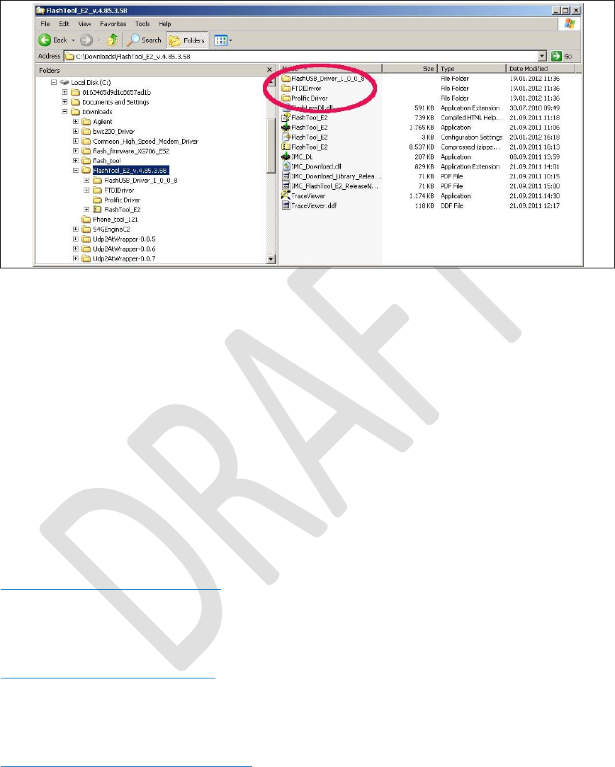
Figure1.LocationoftheProlificserialtoUSBdriver,theFlash
USBdriverandtheFTDIdiverwithintheflashtool
folder.
Pls note that Win does not always complain if the drivers 4 to 5 are not installed. If one of these drivers is missing flashing problems are occurring.
TheARMsoftwareandLTEfirmwarereleasesarelinkedto
individualdriverrevisionnumbersthatwereusedforrelease
testing.TheyweretypicallypublishedtogetherwiththeARM
softwareandtheLTEfirmwarehere:
http://wiki.imu.imc.local/XG716_LTE_CV_Setup_versions
Thelatestdriverscanbefoundhere:
\\musdsara001.imu.imc.local\SW_builds\xmm6360\tools
Orifsomethingismissinghere:
\\musdsara001.imu.imc.local\SW_builds\xmm7060\Release\Tools
Whichissimilarto

RevisionHistory
Rev.1.0,September‐201214/60
HardwareUserGuide,DocumentNumber:N/A
M:\Software\XMM7060_toolsatIMCDRS
FlashTool:
\\musdsara001.imu.imc.local\SW_builds\xmm6360\tools\flashtool
Socmondll:
\\musdsara001.imu.imc.local\SW_builds\xmm7060\Release\Tools\Socmondll\socmondll_100.150.001.dll
2.1.2 IntelHighSpeedModemDriver(ecm200)
Taketherecommendeddriver,seeSubsec.2.1.1,
(foldere.g.WMC_ecm200_3.61.0)andfollowthe
instructionsfromtheinstallationwizard.
EnabletheIPforwarding:runthe
sriptenable_ip_forwarding.regfrom:
\\musdsara001.imu.imc.local\SW_builds\xmm7060\Release\Tools\Intel_High_Speed_Modem
Hint:CopythefiletothelocalPCandthenrunitwithroot
privileges.
NowconnectthecabletotheUSB‐HSconnector.
RevisionHistory
Rev.1.0,September‐201215/60
HardwareUserGuide,DocumentNumber:N/A
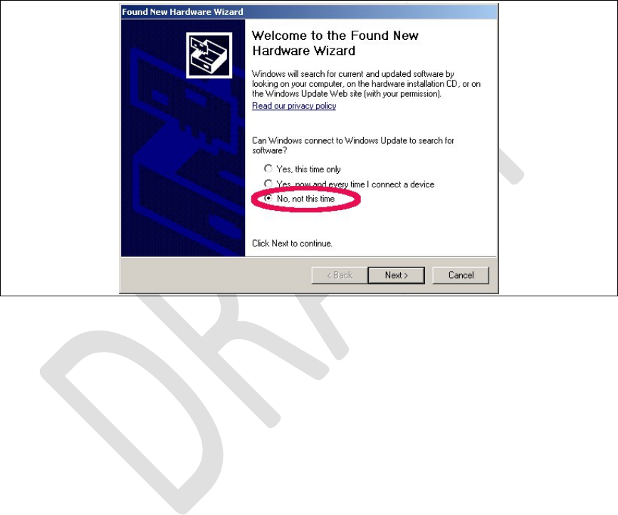
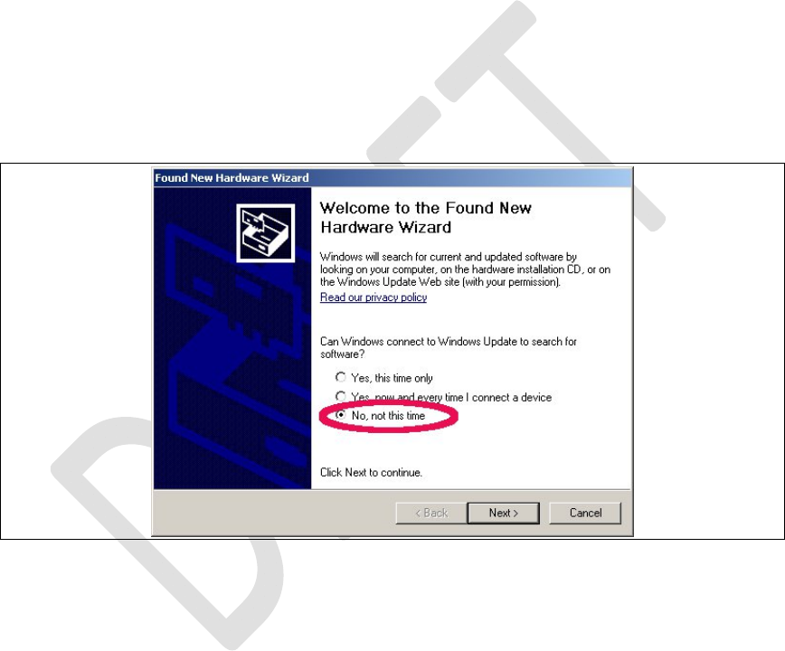
WinXPasksnowit’stypicalquestionsandgetsthecommon
answersseebelow.Win7doesnotaskandloadsthedriver
automatically.
Figure2.Usethealreadyinstalleddriver.
RevisionHistory
Rev.1.0,September‐201216/60
HardwareUserGuide,DocumentNumber:N/A
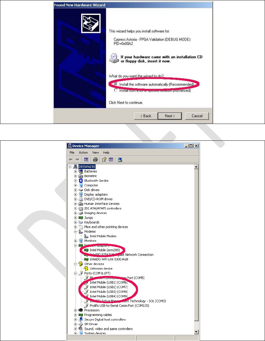
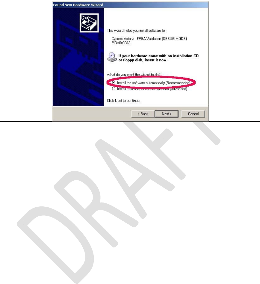
Figure3.Installthedriveragain.
Figure4.ThenetworkmodemandfourCOMportsarenow
appearingatthedevicemanager.
RevisionHistory
Rev.1.0,September‐201217/60
HardwareUserGuide,DocumentNumber:N/A
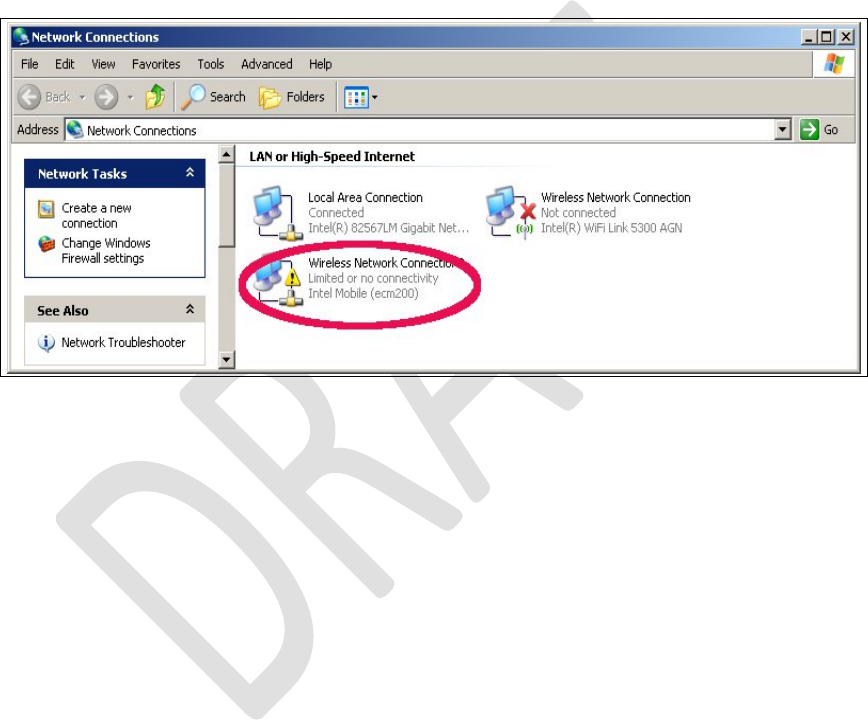
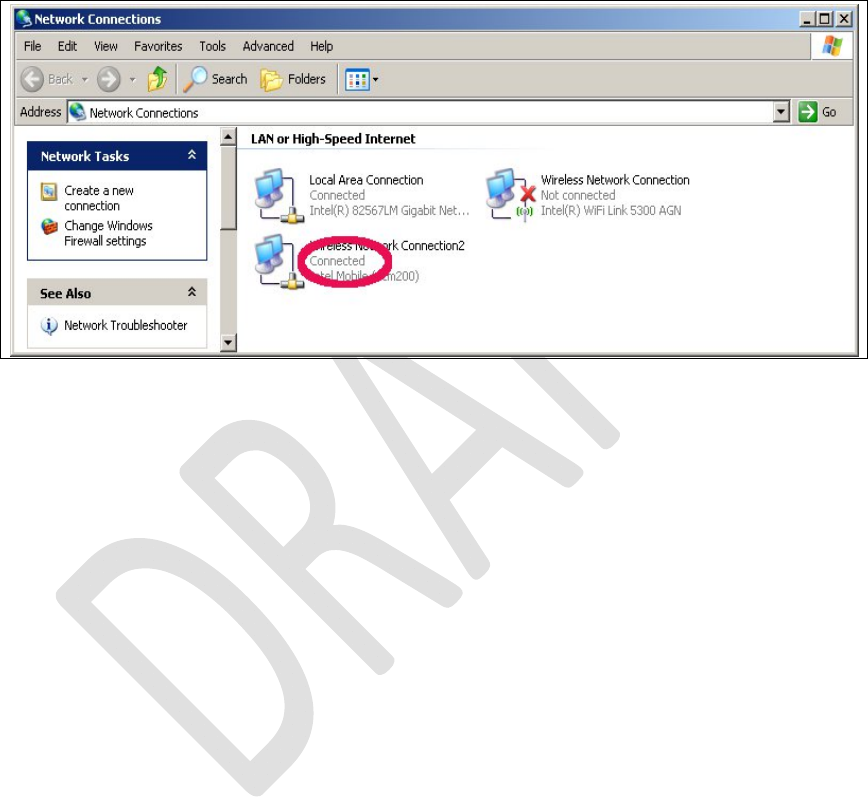
Nowopenthenetworkmanagerandconfigurethe
networksettingsofthemodem.
Figure5.Openthenetworkconnectionsdialog.WinXP:
Start:Settings:NetworkConnectios.Anewnetwork
devicedidpopup.Itisnotyetconnected.
RevisionHistory
Rev.1.0,September‐201218/60
HardwareUserGuide,DocumentNumber:N/A
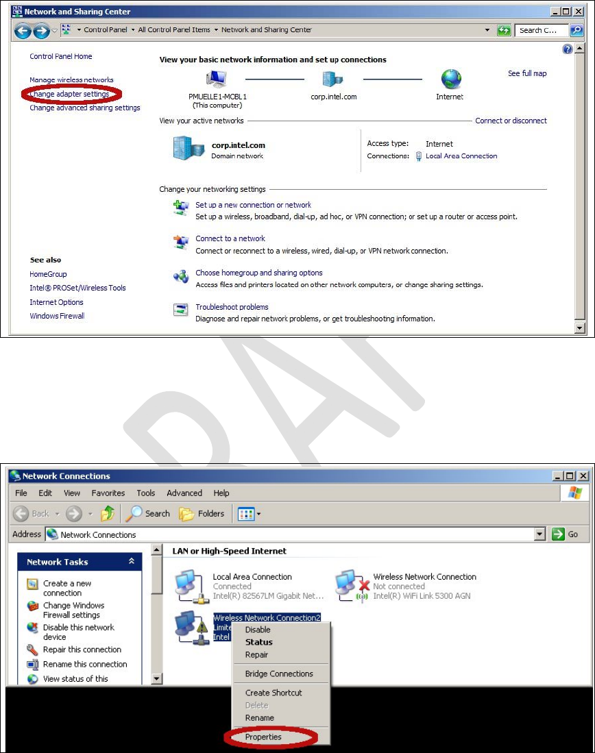
Figure6.OnWin7:Select“Start:ControlPanel:Networkand
SharingCenter”followedby“Changeadapter
settings”.
Figure7.Openthepropertiesdialogofthenewnetwork
device(rightclick).
RevisionHistory
Rev.1.0,September‐201219/60
HardwareUserGuide,DocumentNumber:N/A
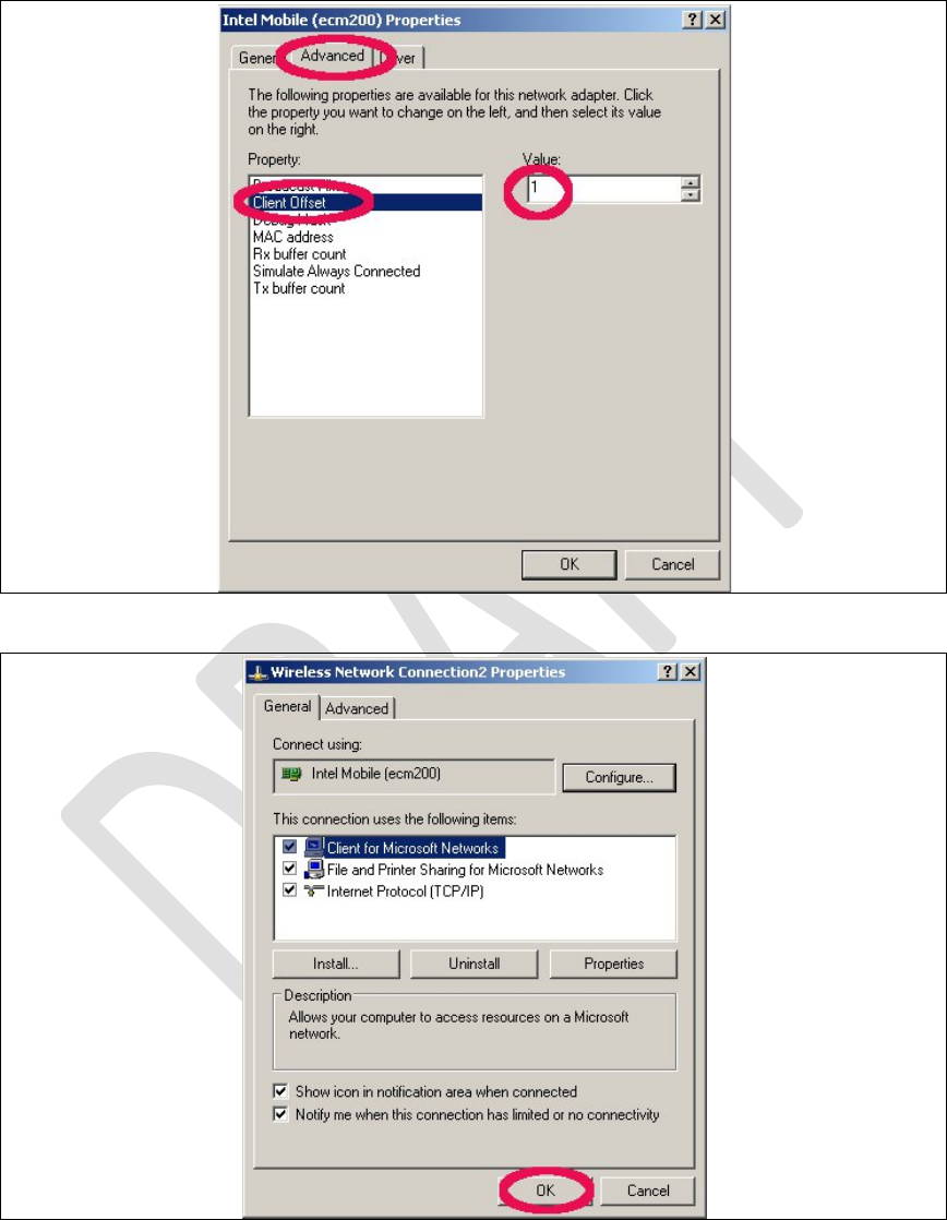
2.1.2.1
Clientoffsetconfiguration.
ThismustbedonebeforetheIPsettings.Iftheorderisflippedthe
IPsettingsgetlost.
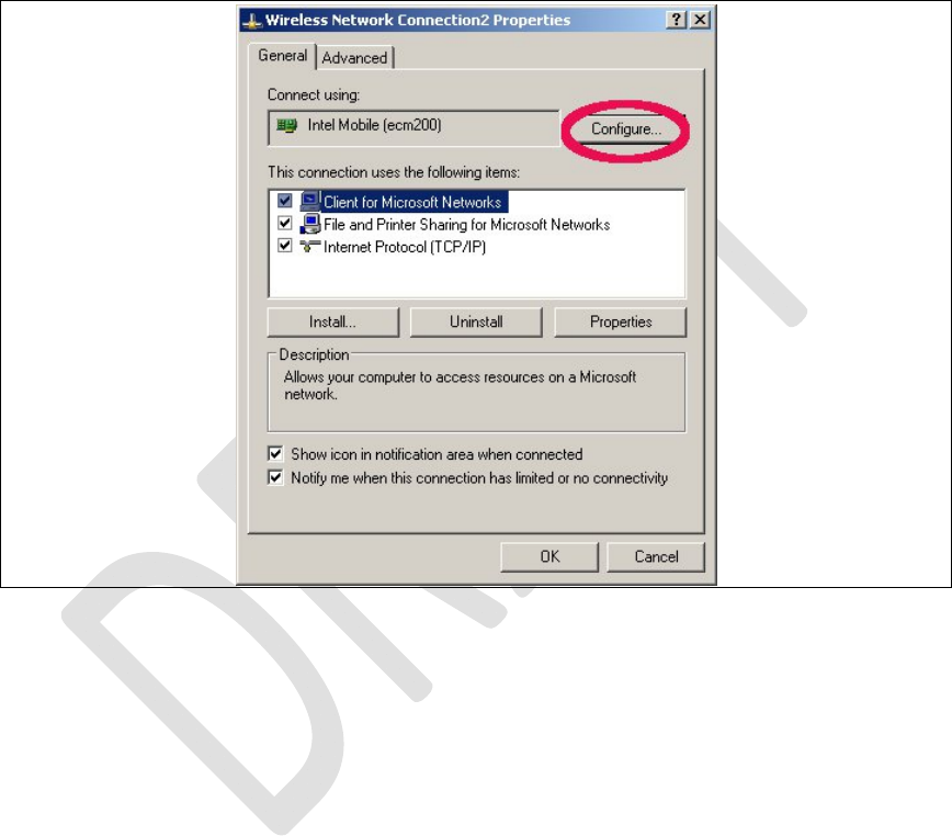
Figure8.Selecttheconfigurationdialog.
RevisionHistory
Rev.1.0,September‐201220/60
HardwareUserGuide,DocumentNumber:N/A
Figure9.Settheclientoffsetto1andpress“OK”.
Figure10.Press“OK”tosavethesesettings.Otherwisethese
settingsgetlost.

RevisionHistory
Rev.1.0,September‐201221/60
HardwareUserGuide,DocumentNumber:N/A
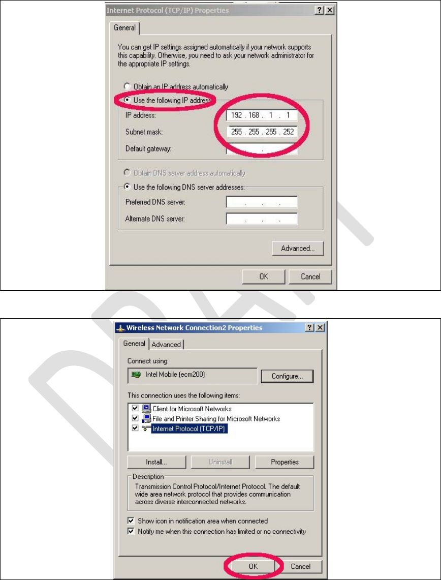
2.1.2.2 StaticIPAddressConfiguration
ThegivenexampleIPnumberatFigure12isfora
simplifiedtestanddebugsetup,seeError!Reference
sourcenotfound.,wheretheoctaveorjavaclient
runsontheWinPCthatalsocarriesallnecessaryWin
driversandisconnectedtotheDUT.Theecm200
driverrunsinasubnetthatisonlyvisiblefromthisPC.
Thecompletesetup,seeError!Referencesourcenot
found.,consistsoftestPCsthatwereprovided
togetherwithrecommendedIPsettingsforthe
ecm200driver.Thestaticroutesettingswereset
typicallyITsystemwide.
IncasetwoPCswereusedtorunthetests,atestPC IncasetwoPCswereusedtorunthetests,atestPC
withthedriversandadesktopPCthatcarriesthe
OctaveortheJavaclientastaticroutemustbesetat

RevisionHistory
Rev.1.0,September‐201222/60
HardwareUserGuide,DocumentNumber:N/A
thedesktopPC.Theexamplebelowhelpstofind
properstaticroutesettings:
testPCwithstaticIP:10.1.0.126
ecm200clientattestPCwithIP:172.16.126.1
(clientoffsetsetto1)
runasrootatthePCwheretheOctaveisrunning
on.
routeprint#readoutroutesettings
routeadd172.16.126.0mask255.255.255.0
10.1.0.126
testtheconfiguration:
ping172.16.126.1#responsefromtheecm200driver
ping172.16.126.2#responsefromthebootedLTE‐IP
block(L1CC)
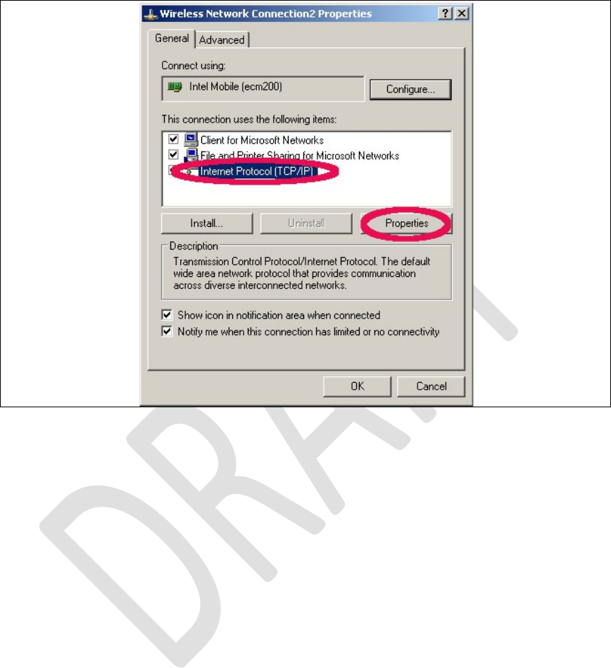
ReopentheNetworkConnectionPropertiesDialog.
RevisionHistory
Rev.1.0,September‐201223/60
HardwareUserGuide,DocumentNumber:N/A
Figure11.OpentheInternetProtocolTCP/IPsettings.
RevisionHistory
Rev.1.0,September‐201224/60
HardwareUserGuide,DocumentNumber:N/A
Figure12.SetthestaticNetworkIPandpressOK.
RevisionHistory
Rev.1.0,September‐201225/60
HardwareUserGuide,DocumentNumber:N/A
Figure13.Toclosethepropertiesdialogandsavethesettings
press“OK”.
Figure14.Congratulations.Yourecm200driveranditsIP
connectionarenowproperlyconfigured.
Ifdesireditisnowalsopossibletorenamethe
networkdevicefrom“WirelessConnection2”to
somethingmoreconveniente.g.ecm200+IPaddress.
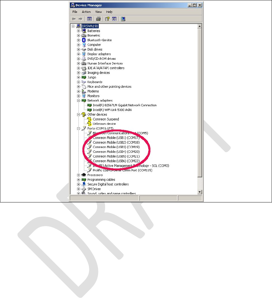
2.1.3 ComneonHighSpeedModemDriver
Taketherecommendeddriver,
\\musdsara001.imu.imc.local\SW_builds\x
mm6360\tools\usb_drivers
See also SMS02534274: ‐Pleaseuse3.46
RevisionHistory
Rev.1.0,September‐201226/60
HardwareUserGuide,DocumentNumber:N/A
versionandnotWMC_comneon2_3.55.0,seeSubsec.
2.1.1,(folderComneon_High_Speed_Modem_Driver)
andfollowtheinstructionsfromtheinstallation
wizard.
Now connect the cable to the USB-HS connector.
Win XP asks now it’s typical questions again and gets the common answers, see below. Win 7 does not ask and loads the driver
automatically.
Figure15.Usethealreadyinstalleddriver.
RevisionHistory
Rev.1.0,September‐201227/60
HardwareUserGuide,DocumentNumber:N/A
Figure16.Installthedriver.
RevisionHistory
Rev.1.0,September‐201228/60
HardwareUserGuide,DocumentNumber:N/A
Figure17.ComneonsuspendandsixCOMportsarenow
appearingatthedevicemanager.
Congratulations,yourdriverinstallationhasfinished
successfully.
2.1.4 FlashUSBdriverandFTDIDriver
ThesedriversaremandatorytoflashnewARMsoftwareandLTE
firmwareimagesatthemodemboard.Taketherecommended

RevisionHistory
Rev.1.0,September‐201229/60
HardwareUserGuide,DocumentNumber:N/A
drivers,seeSubsec.2.1.1,(flashtoolsubfolder)andfollowthe
instructionsfromtheinstallationwizards.
Note: Ifthisdriversarenotinstalledcorrectlyinstabilitiesat
theflashprocessareoccurringwithoutsubstantialerror
informationfromWinXPorWin7.
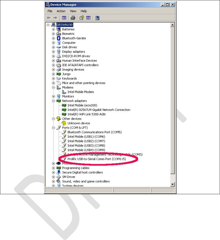
2.1.5 ProlificSerialtoUSBDriver
TheProlificdriverismandatorytoaccessallmodemboardUART
(USIF)ports.Taketherecommendeddriver,seeSubsec.2.1.1,
(folderProlificDriver)andfollowtheinstructionsfromthe
installationwizard.
ConnecttheUSBcabletothedesiredUSIFportandcheckthatthe
COMportappearscorrectlyintheWindevicemanager.
(Win:Settings:ControlPanel:SystemProperties:Hardware:Device
Manager.ThisisquitesimilartofindatWinXPandWin7.)
RevisionHistory
Rev.1.0,September‐201230/60
HardwareUserGuide,DocumentNumber:N/A
Figure18.USIF1DeviceManagerProlificUSB‐to‐SerialCOM
Port
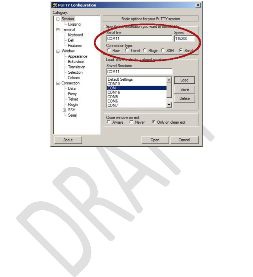
2.2
LTEdebugUARTconfiguration
Afterthepreliminarysetting,runanyATterminalapplication(e.g.
HyperTerminal)onyourPC’scommunicationport,withthe
followingsettings.

RevisionHistory
Rev.1.0,September‐201231/60
HardwareUserGuide,DocumentNumber:N/A
Table1.TerminalPortSettings
Datarate115200bps
DataBits8
ParityN
StopBits1
FlowControlHW
onUNIXxtermusethiswithuucp:
%docing station serial port, uucp
chown uucp /dev/ttyUSB0
cu -l /dev/ttyUSB0 -s 115200
Ifputtyhttp://www.putty.orgisusedthislooks
likethis:
RevisionHistory
Rev.1.0,September‐201232/60
HardwareUserGuide,DocumentNumber:N/A
Figure19.Puttyconfiguration.

RevisionHistory
Rev.1.0,September‐201233/60
HardwareUserGuide,DocumentNumber:N/A
2.3 SystemTraceBox
2.3.1 SetupandConfiguration
2.3.1.1 EnteringATCommands
TheATcommandsmentionedbelowmustbesenttotheCOM
portthatcorrespondstothe
IntelMobile(USB3)COMportincasetheecm200
driverisusedor
totheCOMportthatcorrespondstotheComneon
HighSpeedModem,seeError!Referencesourcenot
found..
TheCOMportthatcorrespondstotheUSIF‐1USBport,seeError!TheCOMportthatcorrespondstotheUSIF‐1USBport,seeError!
Referencesourcenotfound.mayalsowork.
Theudp2ATservercanbeusedtoenterlocalATcommandsfromTheudp2ATservercanbeusedtoenterlocalATcommandsfrom
remotelocations,seeSubsec.Error!Referencesourcenotfound..

RevisionHistory
Rev.1.0,September‐201234/60
HardwareUserGuide,DocumentNumber:N/A
2.3.1.2 BoardConfigurationandrequiredATCommands
Resettheboardinawaythatisbootingfromtheflash
Enabletracingusing:at+xsystrace=0,"lte_l1_sw=4"
Resettheboardagaininawaythatisbootingfrom
theflash
Nowtheinitializationatcommandstoswitchto
ServiceMode(thatisthemodetouseRCTTH)canbe
sentifneeded:
ARMforInc2.8:‘at@ecal:’’at@ecal_init():’
ARMforInc3.0:‘at@ephy:smon()’
Note:PleasecheckwiththeprovideroftheARM
imagewhichcommandsarevalidfortheactual
build!!!
TheATcommandsbelowaremandatorytoenabletracing:
a. Enabletracingatallsources:at+trace=1;

RevisionHistory
Rev.1.0,September‐201235/60
HardwareUserGuide,DocumentNumber:N/A
b. RoutetracesthroughUE's"OCT‐Block",which
createstheISTPformat:at+xsio=3;
c. Selectthetracesfromspecificsources,use
at+xystracecommand.Forexample,toconfigure
thetracesfromspecifictoselectONLYthe3g_sw
traces:at+xsystrace=0,"3g_sw=1",,"oct=4"
d. makesureyourSIMisnotwaitingforenteringa
PIN:at+cpin?Ifitis,sendthePINatat+cpin=<sim
pinnumber>
e. makesure,the3Gprotocolstackissendingtraces:
at+cops=0;(thiscommandtriggersthephoneto
(re‐)registertothenetwork)
2.3.2 ConnectingtheUE
6. ConnecttheUEtothePCasdescribedinsection
Error!Referencesourcenotfound..
7. Findthecom‐portinwhichUEisconnectedusing

RevisionHistory
Rev.1.0,September‐201236/60
HardwareUserGuide,DocumentNumber:N/A
7. Findthecom‐portinwhichUEisconnectedusing
comtesttool.Runthecommandcomtest–l.Itwilllist
theports.Carefullyevaluatetheportfortracingand
portforcontrol.
8. TocheckwhetherPCisconnectedtoUEproperly,try
connectingthecontrolportwiththeterminal
emulatorandsend“AT”command,Iftheresponseis
OK,UEisconnectedsuccessfully.Thiscanbedonevia
ATConsoleinSystemTraceTool.
9. SendthebelowATcommands:
a. Enabletracingatallsources:at+trace=1;
b. RoutetracesthroughUE's"OCT‐Block",which
createstheISTPformat:at+xsio=3;
c. Selectthetracesfromspecificsources,use
at+xystracecommand.Forexample,toconfigure

RevisionHistory
Rev.1.0,September‐201237/60
HardwareUserGuide,DocumentNumber:N/A
thetracesfromspecifictoselectONLYthe3g_sw
traces:at+xsystrace=0,"3g_sw=1",,"oct=4"
d. makesureyourSIMisnotwaitingforenteringa
PIN:at+cpin?Ifitis,sendthePINatat+cpin=<sim
pinnumber>
e. makesure,the3Gprotocolstackissendingtraces:
at+cops=0;(thiscommandtriggersthephoneto
(re‐)registertothenetwork)
2.4 ATCommandsExamples
Afterthepreliminarysetting,runanyATterminalapplication(e.g.
HyperTerminal)onyourPC’scommunicationport,withthe
followingsettings

RevisionHistory
Rev.1.0,September‐201238/60
HardwareUserGuide,DocumentNumber:N/A
Table3.TerminalPortSettings
Datarate115200bps
DataBits8
ParityN
StopBits1
FlowControlHW
ATCommandtocheckARMSoftwareversion
Table4.ATCommandstocheckARMsoftwareversion
CommandsentbyDTEResponseofDCEDescription
at+xgendata The device will reply with the running ARM
software version
Registeronthenetwork(GSM/UMTS)
Table5.ATCommandstoRegisterontheNetwork
CommandsentbyDTEResponseofDCEDescription
AT+XRAT=1,2 selectradioaccesstechnology:1=GSM/UMTSDualmode;2=UMTS
OK
AT+COPS=0 Registerthephoneonthenetwork
OK
AT+CREG? Verifyregistration
+CREG:0,1
OK
AT+COPS?
+COPS:0,0,"AT&T",0Readoperatorname
IncomingVoiceCall
Table6.ATCommandsforanIncomingCall
CommandsentbyDTEDCEResponseDescription
ATA
OK

RevisionHistory
Rev.1.0,September‐201239/60
HardwareUserGuide,DocumentNumber:N/A
OutgoingVoiceCall
Table7.ATCommandsforanOutgoingCall
CommandsentbyDTEDCEResponseDescription
AT
OK
AT+CLIP=1 ActivationofCallerlineID
presentation
OK
ATD+862161019000; Outgoingvoicecall
OKVoicecallisacceptfromnetwork
ATHHangup
OK
SMSManagement
Table8.ATCommandsforSMSManagement
CommandsentbyDTEDCEResponseDescription
AT+CMGF=1OKSetthetextmodeastheformatthatwillbeused.Tobesetbeforeofthefirst
operation
AT+CMGF=0OKSetthePDUmodeastheformatthatwillbeused.Tobesetbeforeofthefirst
operation
AT+CMGS=”0171112233”<CR>
“Thisisthetext”<ctrl‐Z>
CMGS:<mr>[,<scts>]
ifPDUmode(+CMGF=0):
+CMGS=<length><CR>PDUis
CMGS:<mr>[,<ackpdu>]
given<ctrl‐Z/ESC>OK
or
CMSERROR:<error>
Testcommand
AT+CMGS=?
OK

RevisionHistory
Rev.1.0,September‐201240/60
HardwareUserGuide,DocumentNumber:N/A

RevisionHistory
Rev.1.0,September‐201241/60
HardwareUserGuide,DocumentNumber:N/A
RevisionHistory
Rev.1.0,September‐201242/60
HardwareUserGuide,DocumentNumber:N/A
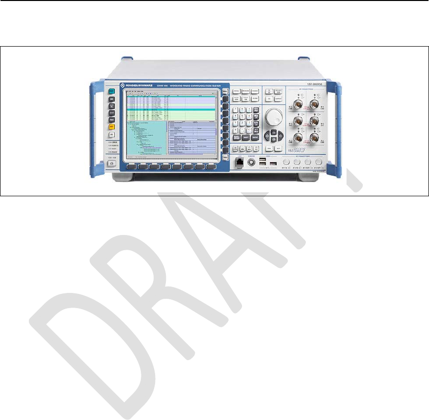
3
TestCases
3.1
ProtocolTest(CMW500)
Figure20.CMW500
IngeneralitneedstobecheckedthatCMW500setupare
identicallytothereference.Thecomponentstobecheckedare:
Thetestscenarioconfigurations(xmlfiles)and
Thefirmwareversionsforthetesterhardwareitself.
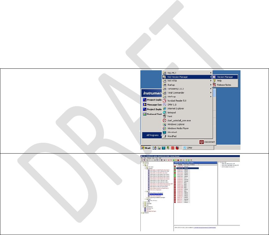
3.1.1 CWM500Firmware
ThefirmwareversioncanbecheckedandmaintainedintheR&S
VersionManager.Basicinformationonsoftwareupdateand
installationwiththeR&SVersionManagerisgiveninthe"R&S
RevisionHistory
Rev.1.0,September‐201243/60
HardwareUserGuide,DocumentNumber:N/A
CMW500ProtocolTesting"quickstartguide(1202.3857.62).The
R&SVersionManagerhelpprovidesmoredetailsonR&SVersion
Managerfunctionsandhandlingofsoftwareunits.Thisdocument
assumesthatallrequiredsoftwareunitscanbeinstalledbythe
user.
TheR&SVersionManagercanbeopenedviatheSTARTmenu:
Onceopenedtherearetwowaystoverifysimilarityoffirmwareversions:
byhandviasteppingthroughthelicenseoptionsor
byexportingthefirmware(softwarestatus).
Thepictureshowstheversionmanagerwiththesteppingthrougheachfirmwarelicense:
RevisionHistory
Rev.1.0,September‐201244/60
HardwareUserGuide,DocumentNumber:N/A
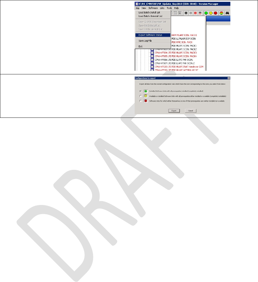
Thenextpictureshowsthemenufromwhichthestatusexportcanbecalled:
Afterthisapop‐upwindowappearswiththreepossiblechoices.Onlythetoponehastobeselectedas
showninthepicture:
Afterthisthelocationofthestatusexportfileneedstobechosen.Oncedonethefilecanbecomparedto
thereferencefilewhichislocatedunder:
..\version\lab2\lab2_cfg.html
3.1.2 TestScenario
Thetestscenarioml_002EPS‐BearerSetupisusedforthissetup
andiscontainedbytheSWoptionKF500withMLAPIExample
Scenarios.
Thepathtotheconfigurationdirectoryisfollowing:
c:\Rohde‐
Schwarz\Scenarios\16.6_callSetup_1\APPL\MLAPI\LTE_SAMPLE_S
CN\1.0\ml_002\msg

RevisionHistory
Rev.1.0,September‐201245/60
HardwareUserGuide,DocumentNumber:N/A
Thedirectory“msg”ispartoftheCDKdeliveryandcontains
severalxmlfiles.Ithastobenotedthatthexmlversionofthexml
filesneedstobecomplianttotheinstalledtesterfirmware.
Otherwisestrangeerrorsoccurduringtestcaseexecution!
http://www2.rohde-
schwarz.com/en/products/test_and_measurement/m
obile_radio/CMW500-|-Demo-|-48-|-5420.html
3.1.3 ATCommands
NetworkattachinCallBoxMode,LTEband7.
at+xact=6,2,1,107
at+cgdcont=1,"IP",”www.rohde-schwarz.com”
ThisgivesOKiftheSIMcartisinsertedaccurately.
at+cops=1,2,"00101",7
3.1.4 TheDataApplicationUnit
InstalltheDataApplicationUnit

RevisionHistory
Rev.1.0,September‐201246/60
HardwareUserGuide,DocumentNumber:N/A
TheDataApplicationUnit(DAU)packagehastobeinstalledon
theCMW.
IncasetheDAUhardwareispopulated,thesoftware(SW)should
alreadybeinstalledaswell.Checkthisin"SetupSW/HW‐
EquipmentInstalledsoftware".
Beforeinstallation:
TerminatetheCMWBaseSWapplication–closethe
windowwith‘X’
Inthetaskmanagerkilltheprocess
"ComponentEnvironmentServer_2.5.exe".
Installation:
InstalltheDAU‐SWpackage
"SetupCMW_DAU_Support(Release)‐V1.0.15.22"
directlyontheCMW.
ReboottheCMWdevice.
RevisionHistory
Rev.1.0,September‐201247/60
HardwareUserGuide,DocumentNumber:N/A
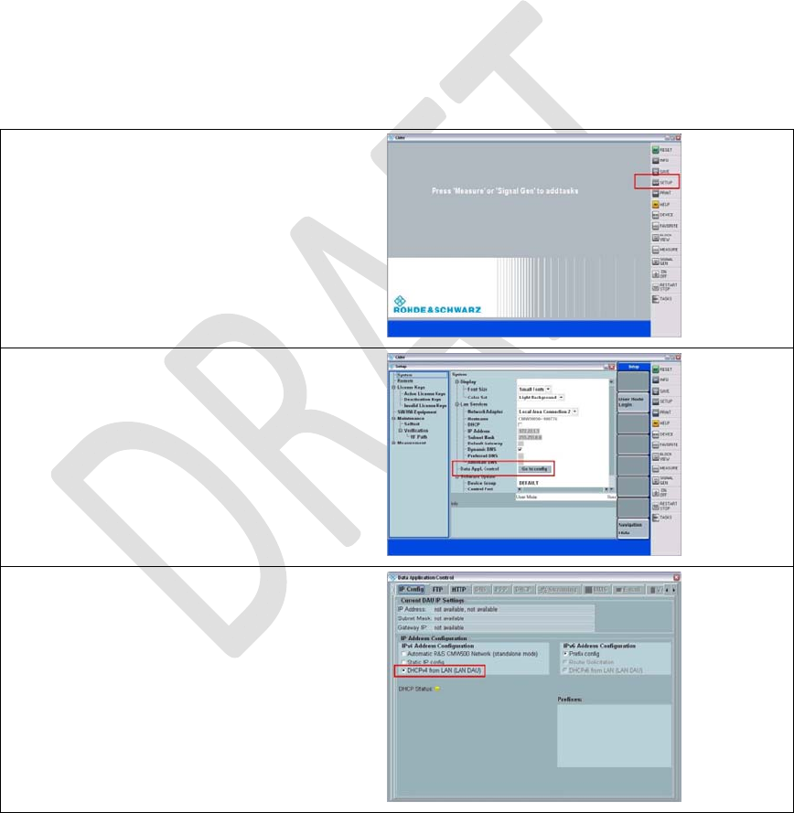
ActivateDHCPinDataApplicationControl
AftercompletestartupoftheCMWBaseSWapplication,follow
thestepsbelowtoconfiguretheDAUforDHCP:
MakesureyourRouterisconnectedtothe"LANDAU"ETHportatthebacksideoftheCMW.
OpentheSETUPmenuontherightside.
OpentheDAUconfigurationviamenu:
DataAppl.ControlGotoconfig
ConfiguretheDAUtouseDHCP
Asshownonthescreenshot,chooselastcheckmark
DHCPv4fromLAN(LANDAU)forIPv4AddressConfiguration
ClosetheCMWBaseSW(ALT+F4)andstartitagainafterwardsbyaDoubleClickonthedesktop
link"CMW1.0"
Aftertherestart,checkthe"DHCPStatus"inthesamewindow.AgreenlightindicatesthattheDAU
couldacquireanIPv4addressviaDHCP.

RevisionHistory
Rev.1.0,September‐201248/60
HardwareUserGuide,DocumentNumber:N/A
SwitchingUPCfromPPC(SUW)toDAU
InordertoletthescenariousetheUPC(=UplaneControl)onthe
DAU(andnotasperdefaultonthePPC),twoXMLfileshaveto
bereplacedinthetopology:
sequencer.xml,
pipe.xml
CopythesetwofilestoC:\Rohde‐
Schwarz\Scenarios\16.6\APPL\MLAPI\rstopology\LTE\.
NOTE:
Itisrecommendedtomakeaback‐upoftheoriginalfilesbefore.
StarttheLTEscenario
StarttheLTEscenarionow.
DuringtheDefaultEPSBearerSetuptheUEwillgetanIPaddress
whichwasacquiredbytheDAUbefore.
RevisionHistory
Rev.1.0,September‐201249/60
HardwareUserGuide,DocumentNumber:N/A
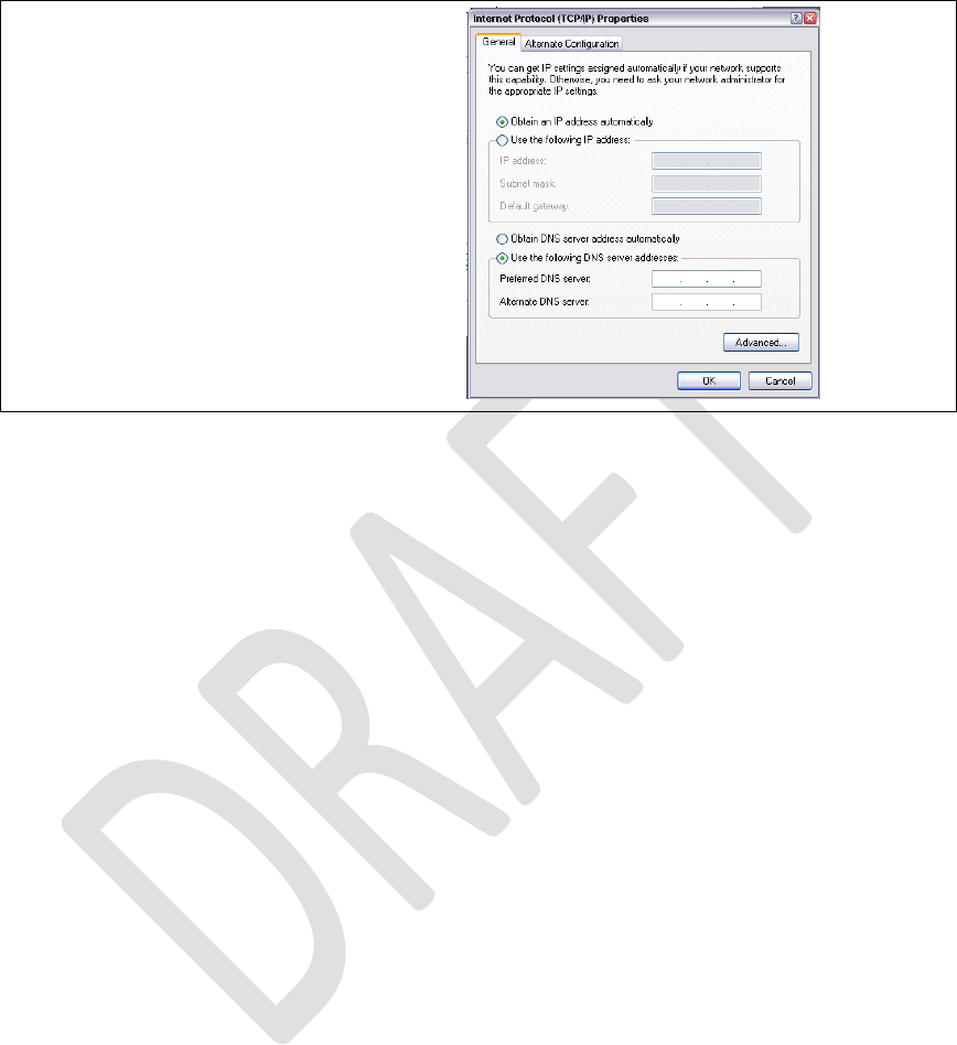
ManualDNSsettings
OntheLTEhostwhichconnectstotheinternet,theDNSserverhastobeconfiguredmanually,
becausetheDAUdoesnotyetsupportautomaticDNSprovisioning(askyourIT).
IncaseofaLTEnotebookadapter,theDNSserverwillbeconfiguredontheIPpropertiespane:

RevisionHistory
Rev.1.0,September‐201250/60
HardwareUserGuide,DocumentNumber:N/A
4 RegulatoryNotice
Japanese Radio Law and Japanese Telecommunications Business Law Compliance.
This device is granted pursuant to the Japanese Radio Law (電波法)
and the Japanese Telecommunications Business Law (電気通信事業法)
This device should not be modified (otherwise the granted designation number will
become invalid)
Manual Information to the End User :
The OEM integrator has to be aware the end user manual shall include all required regulatory information/warning as show in this manual.

RevisionHistory
Rev.1.0,September‐201251/60
HardwareUserGuide,DocumentNumber:N/A
5 Abbreviations/Terminology
A
A‐GPSAssisted‐GPS(GlobalPositioningSystem)
APApplicationProcessor
B
BBBaseband
C
CMOSComplementaryMetalOxideSemiconductor
CNComneon
D
DigRFv4DigitalRFinterfacev4(rmainlyusedfor4G)
DigRF3.09DigitalRFinterfacev3for(mainlyusedfor2G/3G)
E
ETMEmbeddedTraceMacrocell
ESDElectrostaticdischarge
F
fpsFramesPerSecond
G
GPIOGeneralpurposeinput/output
GSMGlobalSystemforMobileCommunications
H
USB‐HSHighSpeed.USB2.0(480MBit/sec)
I
J
JPEGJointPhotographicExpertsGroup
JTAGJointTestActionGroup

RevisionHistory
Rev.1.0,September‐201252/60
HardwareUserGuide,DocumentNumber:N/A
L
LDOLowdropout(regulator)
LEDLight‐emittingdiode
M
MIPIMobileIndustryProcessorInterface
MMC(I)MultimediaCard(Interface)
MPUMicroprocessorunit
O
P
PAPowerAmplifier
PCLPortControlLogic
PMUPowerManagementunit
PTIParallelTraceInterface
S
SD‐CardSecureDigitalCard
SMTpinheaderSurfaceMountTechnologypinheader
SPISerialPeripheralinterface
S4GSMARTi™4G
STMIPISystemTraceMIPI
STTSystemTraceTool
SVBSystemverificationboard
SWSoftware
T
TAPTestAccessPort
TCUTestControlUnit
U
USBUniversalSerialBus
USIFUniversalSerialInterface

RevisionHistory
Rev.1.0,September‐201253/60
HardwareUserGuide,DocumentNumber:N/A
AppendixA Definitions/Explanations
EvalBoardspecialprocessorsocketboardforX‐GOLD™716componentverification
LauterbachSupplierofDebugandTraceenvironmentforX‐GOLD™716(e.g.JTAG,ETM7/11,STMIPI)
ModemboardMainpartofXMM™7160platformhardware(seeError!Referencesourcenotfound.)
XMM™7160ProjectnameofIntelplatformwithkeycomponentX‐GOLD™716
RF‐EngineRFpartofplatform(RF‐transceiver,Poweramplifiers,LNA,Filterbank,antennaswitchetc.).
SMARTi™4GIntelRF‐transceiverfor2G/3G/4G
JanusboardBoardwithSMARTi™LUandSMARTi™UE2
CarrierboardSMBneedsacarrierboardforoperation

RevisionHistory
Rev.1.0,September‐201254/60
HardwareUserGuide,DocumentNumber:N/A
AppendixBRegulatoryStatements
USAFCCRadioFrequencyExposure
The FCC with its action in ET Docket 96-8 has adopted a safety standard for human exposure to radio
frequency (RF) electromagnetic energy emitted by FCC certified equipment. The wireless adapter meets the
Human Exposure limits found in OET Bulletin 65, supplement C, 2001, and ANSI/IEEE C95.1, 1992.
Proper operation of this radio according to the instructions found in this manual will result in exposure
substantially below the FCC’s recommended limits.
The following safety precautions should be observed:
Do not touch or move antenna while the unit is transmitting or receiving.
Do not hold any component containing the radio such that the antenna is very close or touching any exposed parts of
the body, especially the face or eyes, while transmitting.
Do not operate the radio or attempt to transmit data unless the antenna is connected; this behavior may cause damage
to the radio.
Use in specific environments:
The use of wireless adapters in hazardous locations is limited by the constraints posed by the safety
directors of such environments.
The use of electronic devices equipped with wireless adapters on airplanes is governed by rules for each
commercial airline operator.
The use of wireless adapters in hospitals is restricted to the limits set forth by each hospital.
ExplosiveDeviceProximityWarning
Warning: Do not operate a portable transmitter (including this wireless adapter) near unshielded
blasting caps or in an explosive environment unless the transmitter has been modified to be
qualified for such use.

RevisionHistory
Rev.1.0,September‐201255/60
HardwareUserGuide,DocumentNumber:N/A
UseOnAircraftCaution
Caution: Regulations of commercial airline operators and the FCC may prohibit airborne operation
of certain electronic devices equipped with radio-frequency wireless devices (wireless adapters)
including cellular devices because their signals could interfere with critical aircraft instruments.
TheWirelessAdapterandYourHealth
The wireless adapter, like other radio devices, emits radio frequency electromagnetic energy. The
level of energy emitted by the wireless adapter, however, is less than the electromagnetic energy
emitted by other wireless devices such as mobile phones. The wireless adapter operates within the
guidelines found in radio frequency safety standards and recommendations. These standards and
recommendations reflect the consensus of the scientific community and result from deliberations of
panels and committees of scientists who continually review and interpret the extensive research
literature. In some situations or environments, the use of the wireless adapter may be restricted by
the proprietor of the building or responsible representatives of the applicable organization.
Examples of such situations may include:
Using the wireless adapter on board airplanes, or
Using the wireless adapter in any other environment where the risk of interference with other devices or services is
perceived or identified as being harmful.
If you are uncertain of the policy that applies to the use of wireless adapters in a specific
organization or environment (an airport, for example), you are encouraged to ask for authorization
to use the adapter before you turn it on.

RevisionHistory
Rev.1.0,September‐201256/60
HardwareUserGuide,DocumentNumber:N/A
REGULATORYINFORMATION
USA‐FederalCommunicationsCommission(FCC)
No configuration controls are provided for Intel® wireless adapters allowing any change in the
frequency of operations outside the FCC grant of authorization for U.S. operation.
Intel® wireless adapters are intended for OEM integrators only.
If Intel® wireless adapters are to be co-located with any other transmitter additional testing and/or approval by the
FCC will be required.
This wireless adapter complies with Part 15 of the FCC Rules. Operation of the device is subject to
the following two conditions:
This device may not cause harmful interference.
This device must accept any interference that may cause undesired operation.
ClassBDeviceInterferenceStatement
This wireless adapter has been tested and found to comply with the limits for a Class B digital
device, pursuant to Part 15 of the FCC Rules. These limits are designed to provide reasonable
protection against harmful interference in a residential installation. This wireless adapter generates,
uses, and can radiate radio frequency energy. If the wireless adapter is not installed and used in
accordance with the instructions, the wireless adapter may cause harmful interference to radio
communications. There is no guarantee, however, that such interference will not occur in a
particular installation. If this wireless adapter does cause harmful interference to radio or television
reception (which can be determined by turning the equipment off and on), the user is encouraged to
try to correct the interference by taking one or more of the following measures:
Reorient or relocate the receiving antenna of the equipment experiencing the interference.
Increase the distance between the wireless adapter and the equipment experiencing the interference.
Connectthecomputerwiththewirelessadaptertoanoutletonacircuitdifferentfromthattowhichthe
equipmentexperiencingtheinterferenceisconnected.

RevisionHistory
Rev.1.0,September‐201257/60
HardwareUserGuide,DocumentNumber:N/A
Consult the dealer or an experienced radio/TV technician for help.
NOTE: The adapter must be installed and used in strict accordance with the manufacturer's
instructions as described in the user documentation that comes with the product. Any other
installation or use will violate FCC Part 15 regulations.
Canada–IndustryCanada(IC)
This device complies with Industry Canada licence-exempt RSS standard(s). Operation is subject to
the following two conditions: (1) this device may not cause interference, and (2) this device must
accept any interference, including interference that may cause undesired operation of the device.
Cet appareil se conforme aux normes Canada d'Industrie de RSS permis-exempt. L'utilisation est
assujetti aux deux conditions suivantes: (1) cet appareil ne peut pas causer d'interférences, et (2) cet
appareil doit accepter des interférences , y compris des interférences qui peuvent causer
desopérations non désirées de l'appareil.
Under Industry Canada regulations, this radio transmitter may only operate using an antenna of a
type and maximum (or lesser) gain approved for the transmitter by Industry Canada. To reduce
potential radio interference to other users, the antenna type and its gain should be so chosen that the
equivalent isotropically radiated power (e.i.r.p.) is not more than that necessary for successful
communication.
Selon les règlements de Canada d'Industrie, cet émetteur de radio peut seulement fonctionner en
utilisant une antenne du type et de gain maximum (ou moindre) que le gain approuvé pour
l'émetteur par Canada d'Industrie. Pour réduire lesinterférences radio potentielles avec les autres
utilisateurs, le type d'antenne et son gain devraient être choisis de façon à ce que la puissance

RevisionHistory
Rev.1.0,September‐201258/60
HardwareUserGuide,DocumentNumber:N/A
isotrope rayonnée équivalente(P.I.R.E.) ne soit pas supérieure à celle qui est nécessaire pour une
communication réussie.
SafetyApprovalConsiderations
This device has been safety approved as a component and is for use only in complete equipment
where the acceptability of the combination is determined by the appropriate safety agencies. When
installed, consideration must be given to the following:
It must be installed into a compliant host device meeting the requirement of UL/EN/IEC 60950-1 2nd edition
including the general provisions of enclosure design 1.6.2 and specifically paragraph 1.2.6.2 (Fire Enclosure).
The device shall be supplied by a SELV source when installed in the end-use equipment.
A heating test shall be considered in the end-use product for meeting the requirement of UL/EN/IEC 60950-1 2nd
edition.
INFORMATIONFOROEMsandHOSTINTEGRATORS
The guidelines described within this document are provided to OEM integrators installing Intel®
wireless adapters in notebook and tablet PC host platforms. Adherence to these requirements is
necessary to meet the conditions of compliance with FCC rules, including RF exposure. When all
antenna type and placement guidelines described herein are fulfilled the Intel® wireless adapters
may be incorporated into notebook and tablet PC host platforms with no further restrictions. If any
of the guidelines described herein are not satisfied it may be necessary for the OEM or integrator to
perform additional testing and/or obtain additional approval. The OEM or integrator is responsible
to determine the required host regulatory testing and/or obtaining the required host approvals for
compliance.
Intel® wireless adapters are intended for OEMs and host integrators only.
The Intel® wireless adapter FCC Grant of Authorization describes any limited conditions of modular approval.
The Intel® wireless adapters must be operated only within countries that have been approved for operation.

RevisionHistory
Rev.1.0,September‐201259/60
HardwareUserGuide,DocumentNumber:N/A
Changes or modification to Intel® wireless adapters by OEMs, integrators or other third parties is not permitted. Any
changes or modification to Intel® wireless adapters by OEMs, integrators or other third parties will void
authorization to operate the adapter.
SimultaneousTransmissionofIntel®WirelessAdapterswithOtherIntegratedorPlug‐In
Transmitters
Based upon FCC Knowledge Database publication number 616217
https://apps.fcc.gov/oetcf/kdb/forms/FTSSearchResultPage.cfm?id=33240&switch=P, when there
are multiple transmitting devices installed in a host device, an RF exposure transmitting assessment
shall be performed to determine the necessary application and test requirements. OEM integrators
must identify all possible combinations of simultaneous transmission configurations for all
transmitters and antennas installed in the host system. This includes transmitters installed in the
host as mobile devices (>20 cm separation from user) and portable devices (<20 cm separation
from user). OEM integrators should consult the actual FCC KDB 616217 document for all details
in making this assessment to determine if any additional requirements for testing or FCC approval
is necessary.
5.1.1 InformationToBeSuppliedtotheEndUserbytheOEMorIntegrator
The following regulatory and safety notices must be published in documentation supplied to the
end user of the product or system incorporating the Intel® wireless adapter, in compliance with
local regulations. Host system must be labeled with "Contains FCC ID: XXXXXXXX", FCC ID
displayed on label.
The Intel® wireless adapter must be installed and used in strict accordance with the manufacturer's
instructions as described in the user documentation that comes with the product. Intel Corporation
is not responsible for any radio or television interference caused byunauthorized modification of
the devices included with the wireless adapter kit or the substitution or attachment of connecting

RevisionHistory
Rev.1.0,September‐201260/60
HardwareUserGuide,DocumentNumber:N/A
cables and equipment other than that specified by Intel Corporation. The correction of interference
caused by such unauthorized modification, substitution or attachment is the responsibility of the
user. Intel Corporation and authorized resellers or distributors are not liablefor any damage or
violation of government regulations that may arise from the user failing to comply with these
guidelines.