Intel 7272NA WWAN Module Adapter User Manual
Intel Mobile Communications WWAN Module Adapter
UserManual.wiki
>
Intel
>
7272NA User Manual
User Manual
Navigation menu
Upload a User Manual
Namespaces
Wiki Guide
HTML
PDF
Info
Views
User Manual
Discussion / Help
Navigation

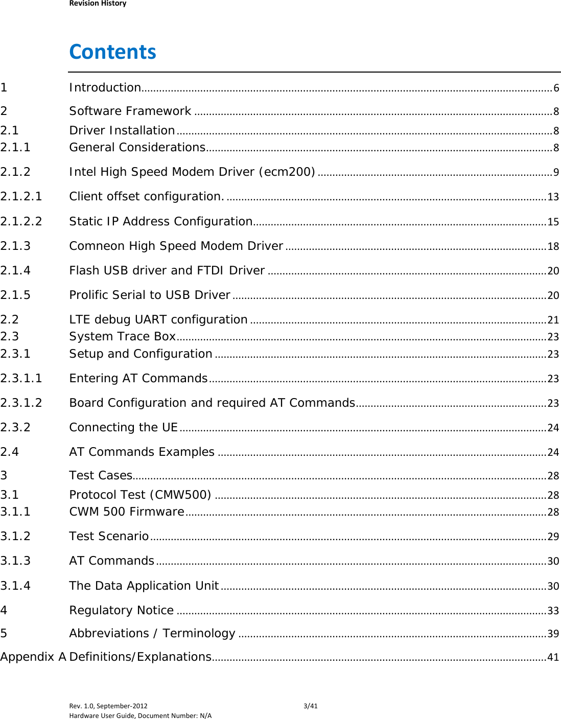

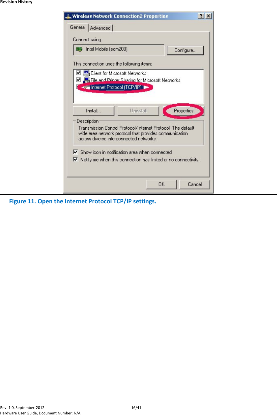
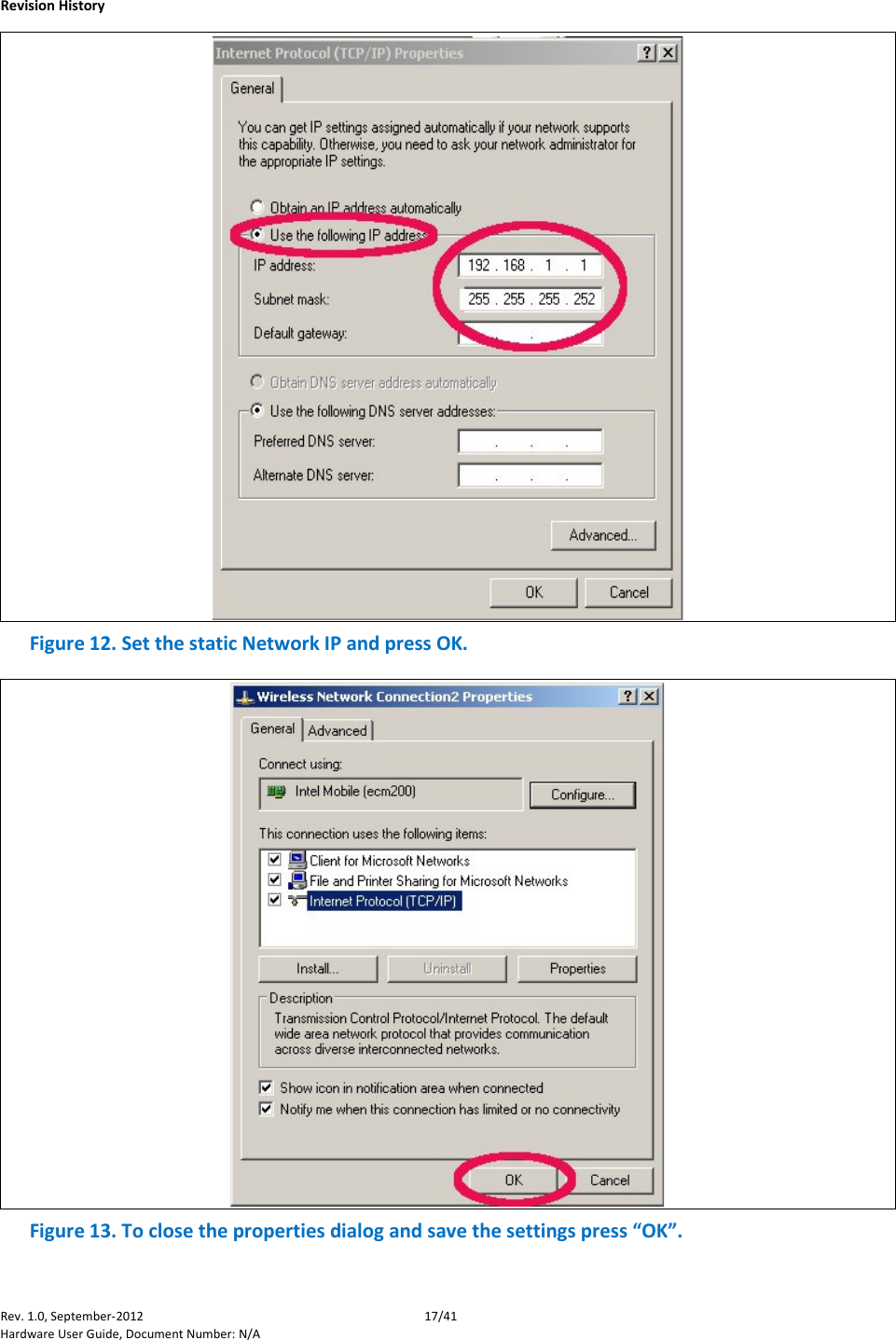
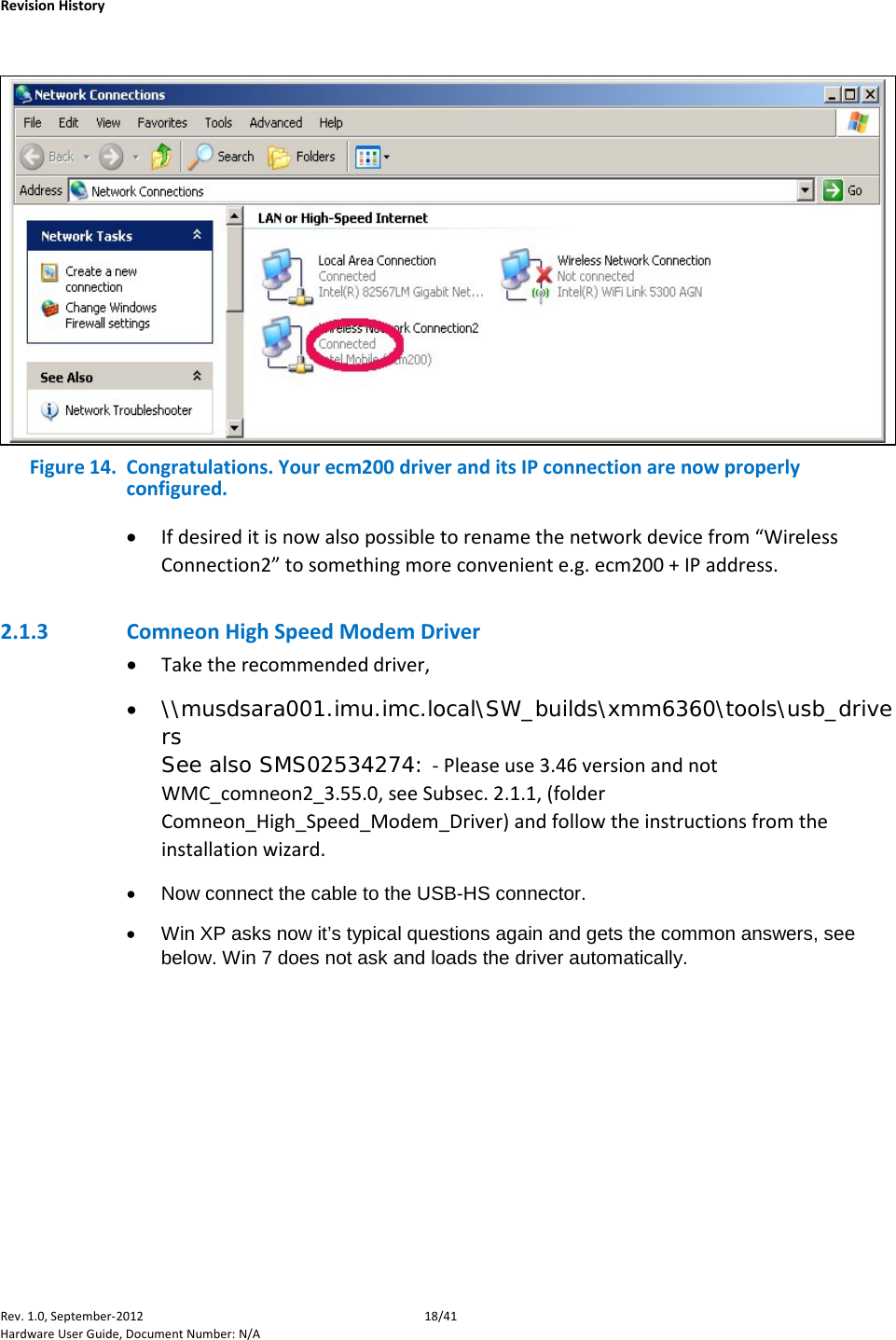
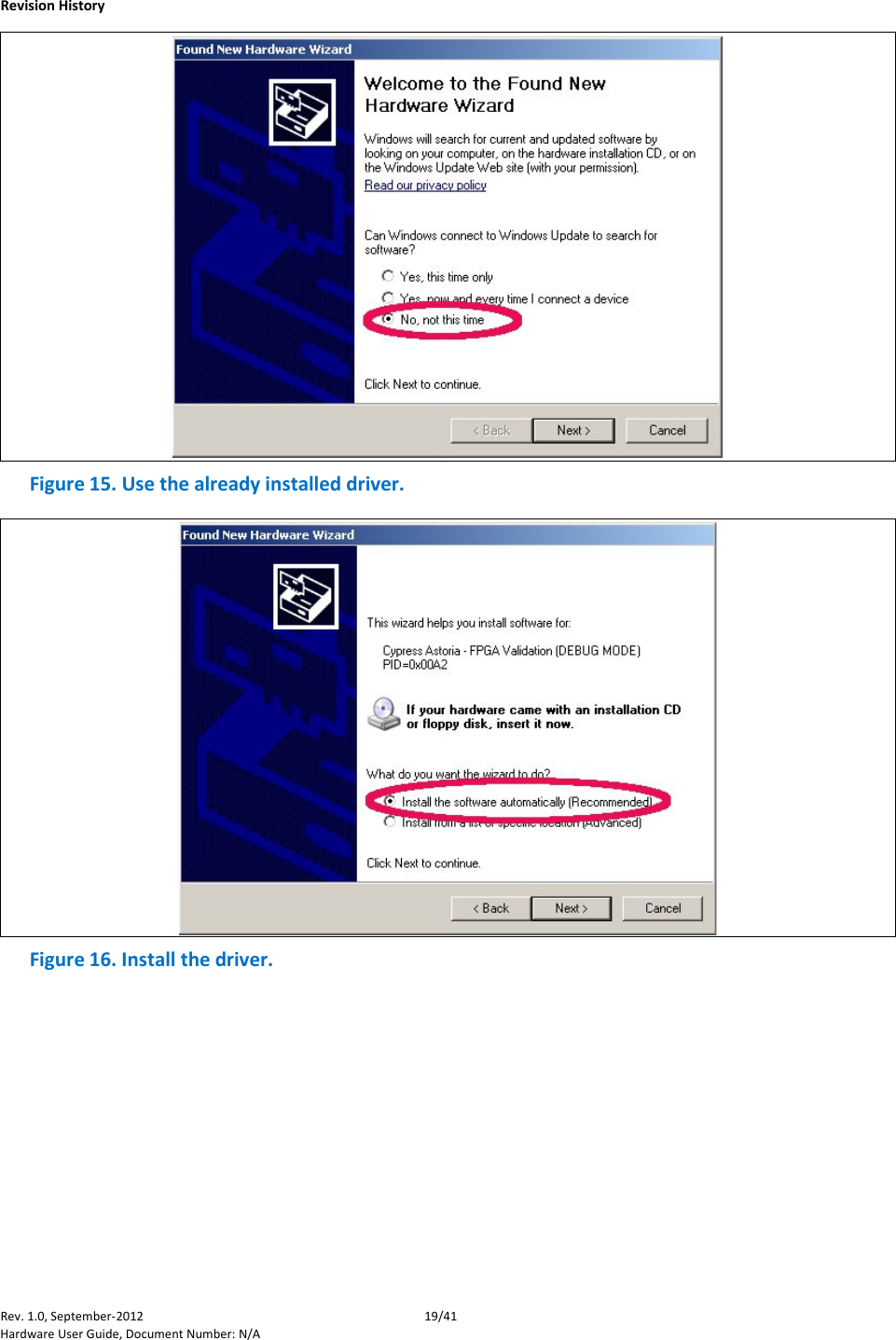
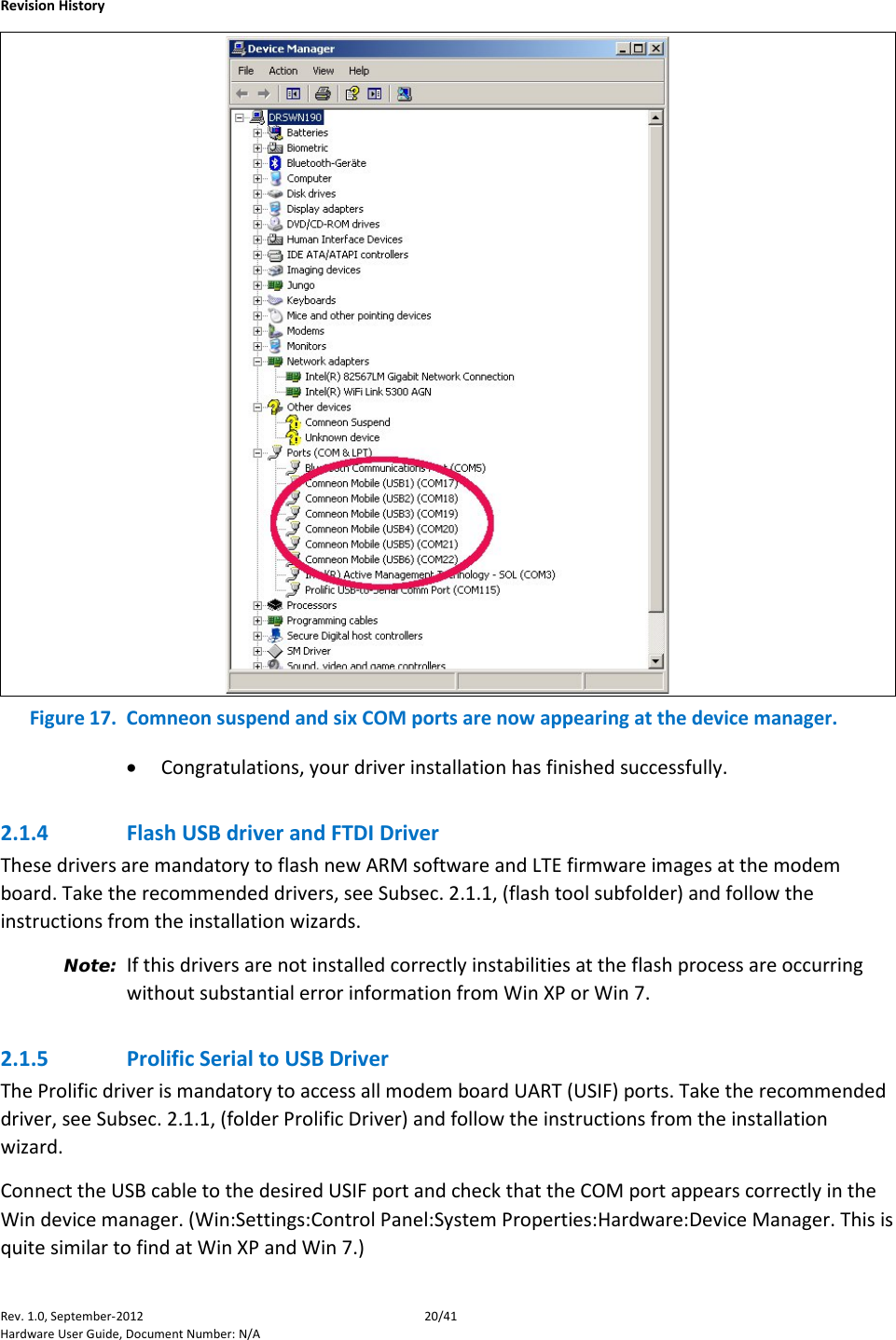
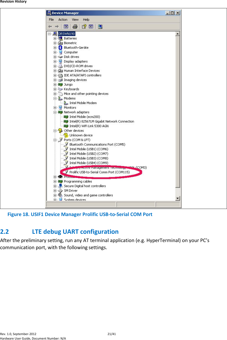
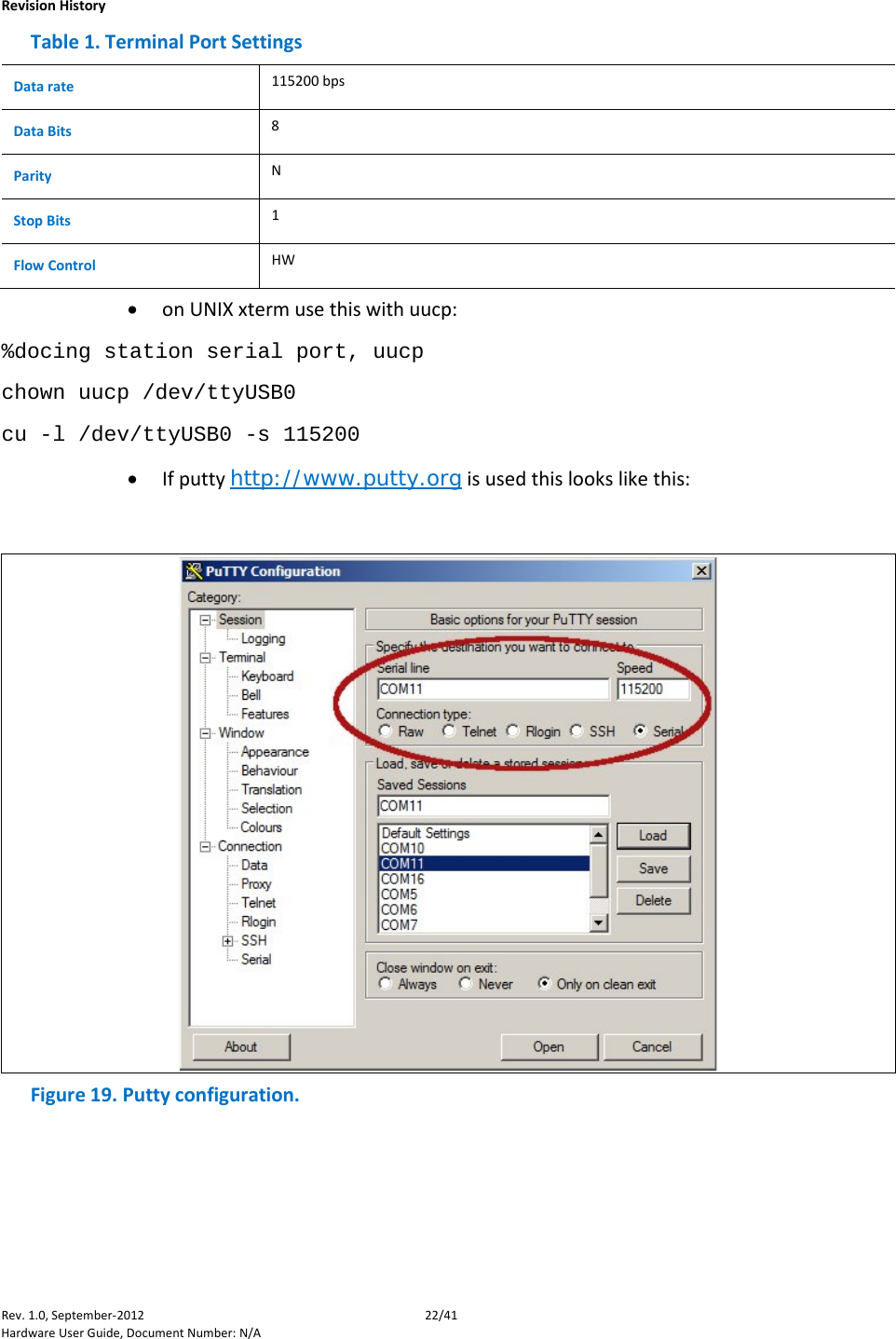
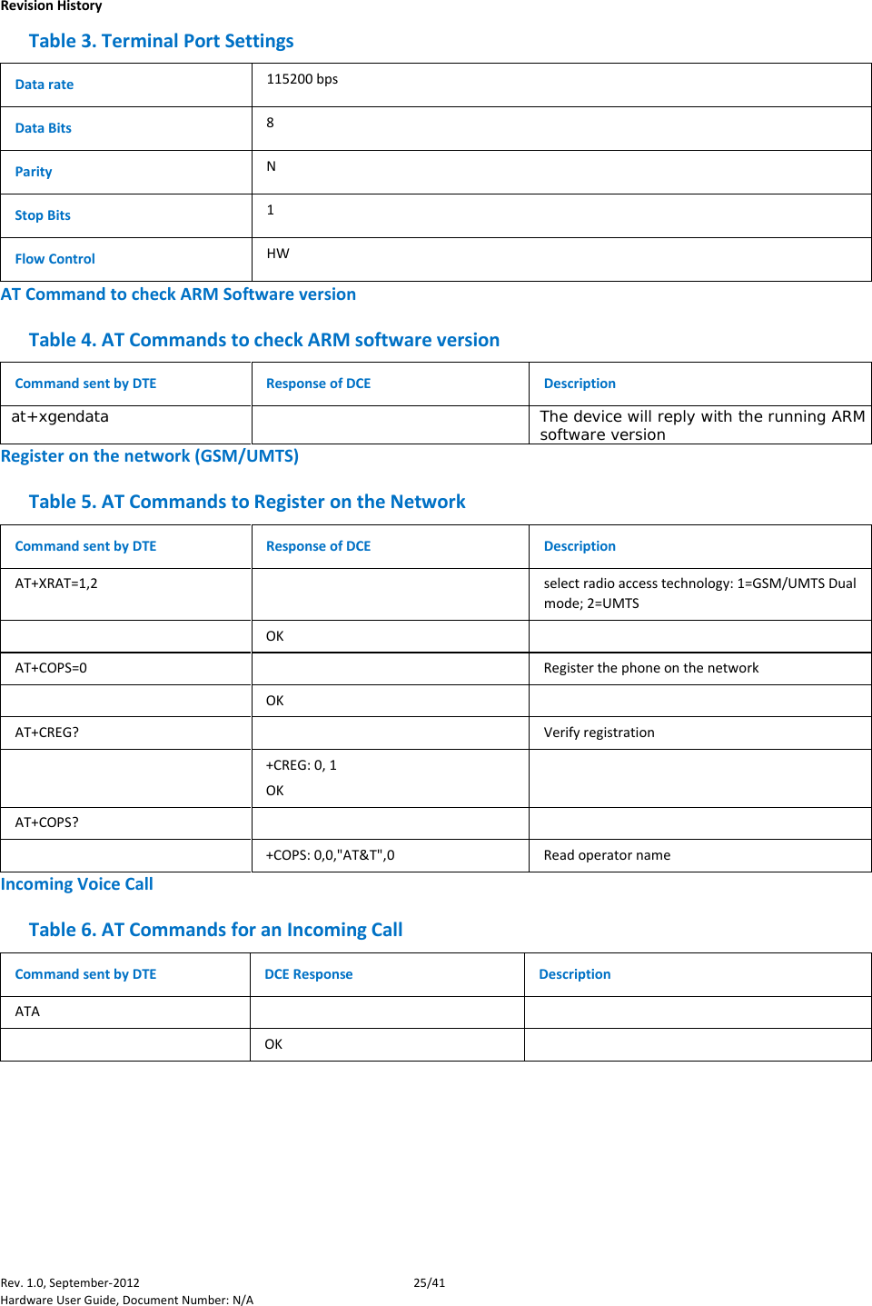
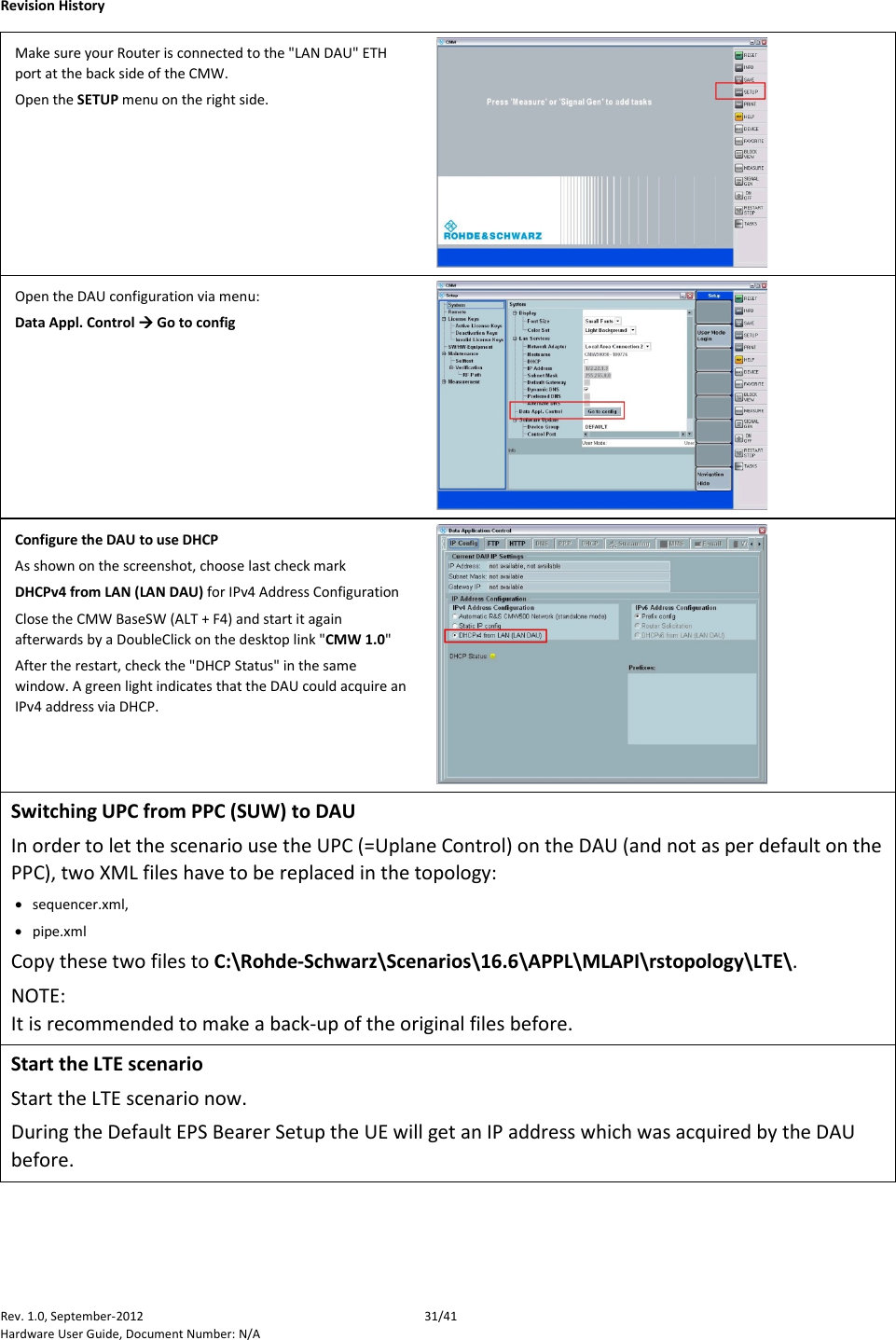
![Revision History Rev. 1.0, September-2012 26/41 Hardware User Guide, Document Number: N/A Outgoing Voice Call Table 7. AT Commands for an Outgoing Call Command sent by DTE DCE Response Description AT OK AT+CLIP=1 Activation of Caller line ID presentation OK ATD+862161019000; Outgoing voice call OK Voice call is accept from network ATH Hang up OK SMS Management Table 8. AT Commands for SMS Management Command sent by DTE DCE Response Description AT+CMGF=1 OK Set the text mode as the format that will be used. To be set before of the first operation AT+CMGF=0 OK Set the PDU mode as the format that will be used. To be set before of the first operation AT+CMGS=”0171112233”<CR> “This is the text”<ctrl-Z> CMGS: <mr>[,<scts>] if PDU mode (+CMGF=0): +CMGS=<length><CR>PDU is CMGS: <mr>[,<ackpdu>] given<ctrl-Z/ESC> OK or CMS ERROR: <error> Test command AT+CMGS=? OK](https://usermanual.wiki/Intel/7272NA/User-Guide-3316343-Page-26.png)