Intel Voice Api 52377002 Users Manual Programming Guide
52377002 to the manual 97bdeefa-fbc3-4826-a45f-7db539dec23e
2015-02-02
: Intel Intel-Voice-Api-52377002-Users-Manual-432674 intel-voice-api-52377002-users-manual-432674 intel pdf
Open the PDF directly: View PDF ![]() .
.
Page Count: 208 [warning: Documents this large are best viewed by clicking the View PDF Link!]
- Contents
- Figures
- Tables
- Revision History
- About This Publication
- 1. Product Description
- 2. Programming Models
- 3. Device Handling
- 4. Event Handling
- 5. Error Handling
- 6. Application Development Guidelines
- 7. Call Progress Analysis
- 7.1 Call Progress Analysis Overview
- 7.2 Call Progress and Call Analysis Terminology
- 7.3 Call Progress Analysis Components
- 7.4 Using Call Progress Analysis on DM3 Boards
- 7.5 Call Progress Analysis Tone Detection on DM3 Boards
- 7.6 Media Tone Detection on DM3 Boards
- 7.7 Default Call Progress Analysis Tone Definitions on DM3 Boards
- 7.8 Modifying Default Call Progress Analysis Tone Definitions on DM3 Boards
- 7.9 Call Progress Analysis Errors
- 7.10 Using Call Progress Analysis on Springware Boards
- 7.11 Call Progress Analysis Tone Detection on Springware Boards
- 7.12 Media Tone Detection on Springware Boards
- 7.13 Default Call Progress Analysis Tone Definitions on Springware Boards
- 7.14 Modifying Default Call Progress Analysis Tone Definitions on Springware Boards
- 7.15 SIT Frequency Detection (Springware Only)
- 7.15.1 Tri-Tone SIT Sequences
- 7.15.2 Setting Tri-Tone SIT Frequency Detection Parameters
- 7.15.3 Obtaining Tri-Tone SIT Frequency Information
- 7.15.4 Global Tone Detection Tone Memory Usage
- 7.15.5 Frequency Detection Errors
- 7.15.6 Setting Single Tone Frequency Detection Parameters
- 7.15.7 Obtaining Single Tone Frequency Information
- 7.16 Cadence Detection in Basic Call Progress Analysis (Springware Only)
- 8. Recording and Playback
- 8.1 Overview of Recording and Playback
- 8.2 Digital Recording and Playback
- 8.3 Play and Record Functions
- 8.4 Play and Record Convenience Functions
- 8.5 Voice Encoding Methods
- 8.6 G.726 Voice Coder
- 8.7 Transaction Record
- 8.8 Silence Compressed Record
- 8.9 Recording with the Voice Activity Detector
- 8.10 Streaming to Board
- 8.11 Pause and Resume Play
- 8.12 Echo Cancellation Resource
- 9. Speed and Volume Control
- 10. Send and Receive FSK Data
- 11. Caller ID
- 12. Cached Prompt Management
- 13. Global Tone Detection and Generation, and Cadenced Tone Generation
- 13.1 Global Tone Detection (GTD)
- 13.1.1 Overview of Global Tone Detection
- 13.1.2 Global Tone Detection on DM3 Boards versus Springware Boards
- 13.1.3 Defining Global Tone Detection Tones
- 13.1.4 Building Tone Templates
- 13.1.5 Working with Tone Templates
- 13.1.6 Retrieving Tone Events
- 13.1.7 Setting GTD Tones as Termination Conditions
- 13.1.8 Maximum Amount of Memory for Tone Templates
- 13.1.9 Estimating Memory
- 13.1.10 Guidelines for Creating User-Defined Tones
- 13.1.11 Global Tone Detection Application
- 13.2 Global Tone Generation (GTG)
- 13.3 Cadenced Tone Generation
- 13.3.1 Using Cadenced Tone Generation
- 13.3.2 How To Generate a Custom Cadenced Tone
- 13.3.3 How To Generate a Non-Cadenced Tone
- 13.3.4 TN_GENCAD Data Structure - Cadenced Tone Generation
- 13.3.5 How To Generate a Standard PBX Call Progress Signal
- 13.3.6 Predefined Set of Standard PBX Call Progress Signals
- 13.3.7 Important Considerations for Using Predefined Call Progress Signals
- 13.1 Global Tone Detection (GTD)
- 14. Global Dial Pulse Detection
- 14.1 Key Features
- 14.2 Global DPD Parameters
- 14.3 Enabling Global DPD
- 14.4 Global DPD Programming Considerations
- 14.5 Retrieving Digits from the Digit Buffer
- 14.6 Retrieving Digits as Events
- 14.7 Dial Pulse Detection Digit Type Reporting
- 14.8 Defines for Digit Type Reporting
- 14.9 Global DPD Programming Procedure
- 14.10 Global DPD Example Code
- 15. R2/MF Signaling
- 16. Syntellect License Automated Attendant
- 17. Building Applications
- Glossary
- Index

Voice API
Programming Guide
June 2005
05-2377-002

Voice API Programming Guide – June 2005
INFORMATION IN THIS DOCUMENT IS PROVIDED IN CONNECTION WITH INTEL® PRODUCTS. NO LICENSE, EXPRESS OR IMPLIED, BY
ESTOPPEL OR OTHERWISE, TO ANY INTELLECTUAL PROPERTY RIGHTS IS GRANTED BY THIS DOCUMENT. EXCEPT AS PROVIDED IN
INTEL'S TERMS AND CONDITIONS OF SALE FOR SUCH PRODUCTS, INTEL ASSUMES NO LIABILITY WHATSOEVER, AND INTEL DISCLAIMS
ANY EXPRESS OR IMPLIED WARRANTY, RELATING TO SALE AND/OR USE OF INTEL PRODUCTS INCLUDING LIABILITY OR WARRANTIES
RELATING TO FITNESS FOR A PARTICULAR PURPOSE, MERCHANTABILITY, OR INFRINGEMENT OF ANY PATENT, COPYRIGHT OR OTHER
INTELLECTUAL PROPERTY RIGHT. Intel products are not intended for use in medical, life saving, or life sustaining applications.
Intel may make changes to specifications and product descriptions at any time, without notice.
This Voice API Programming Guide as well as the software described in it is furnished under license and may only be used or copied in accordance
with the terms of the license. The information in this manual is furnished for informational use only, is subject to change without notice, and should not
be construed as a commitment by Intel Corporation. Intel Corporation assumes no responsibility or liability for any errors or inaccuracies that may
appear in this document or any software that may be provided in association with this document.
Except as permitted by such license, no part of this document may be reproduced, stored in a retrieval system, or transmitted in any form or by any
means without express written consent of Intel Corporation.
Copyright © 2004-2005, Intel Corporation
BunnyPeople, Celeron, Chips, Dialogic, EtherExpress, ETOX, FlashFile, i386, i486, i960, iCOMP, InstantIP, Intel, Intel Centrino, Intel Centrino logo,
Intel logo, Intel386, Intel486, Intel740, IntelDX2, IntelDX4, IntelSX2, Intel Inside, Intel Inside logo, Intel NetBurst, Intel NetMerge, Intel NetStructure,
Intel SingleDriver, Intel SpeedStep, Intel StrataFlash, Intel Xeon, Intel XScale, IPLink, Itanium, MCS, MMX, MMX logo, Optimizer logo, OverDrive,
Paragon, PDCharm, Pentium, Pentium II Xeon, Pentium III Xeon, Performance at Your Command, skoool, Sound Mark, The Computer Inside., The
Journey Inside, VTune, and Xircom are trademarks or registered trademarks of Intel Corporation or its subsidiaries in the United States and other
countries.
* Other names and brands may be claimed as the property of others.
Publication Date: June 2005
Document Number: 05-2377-002
Intel Converged Communications, Inc.
1515 Route 10
Parsippany, NJ 07054
For Technical Support, visit the Intel Telecom Support Resources website at:
http://developer.intel.com/design/telecom/support
For Products and Services Information, visit the Intel Telecom Products website at:
http://www.intel.com/design/network/products/telecom
For Sales Offices and other contact information, visit the Where to Buy Intel Telecom Products page at:
http://www.intel.com/buy/networking/telecom.htm

Voice API Programming Guide – June 2005 3
Contents
Revision History . . . . . . . . . . . . . . . . . . . . . . . . . . . . . . . . . . . . . . . . . . . . . . . . . . . . . . . . . . . . . 11
About This Publication . . . . . . . . . . . . . . . . . . . . . . . . . . . . . . . . . . . . . . . . . . . . . . . . . . . . . . . 13
Purpose . . . . . . . . . . . . . . . . . . . . . . . . . . . . . . . . . . . . . . . . . . . . . . . . . . . . . . . . . . . . . . . 13
Applicability . . . . . . . . . . . . . . . . . . . . . . . . . . . . . . . . . . . . . . . . . . . . . . . . . . . . . . . . . . . . 13
Intended Audience. . . . . . . . . . . . . . . . . . . . . . . . . . . . . . . . . . . . . . . . . . . . . . . . . . . . . . . 13
How to Use This Publication . . . . . . . . . . . . . . . . . . . . . . . . . . . . . . . . . . . . . . . . . . . . . . . 14
Related Information . . . . . . . . . . . . . . . . . . . . . . . . . . . . . . . . . . . . . . . . . . . . . . . . . . . . . . 15
1 Product Description . . . . . . . . . . . . . . . . . . . . . . . . . . . . . . . . . . . . . . . . . . . . . . . . . . . . . . . . . . 17
1.1 Overview . . . . . . . . . . . . . . . . . . . . . . . . . . . . . . . . . . . . . . . . . . . . . . . . . . . . . . . . . . . . . . 17
1.2 R4 API . . . . . . . . . . . . . . . . . . . . . . . . . . . . . . . . . . . . . . . . . . . . . . . . . . . . . . . . . . . . . . . . 17
1.3 Call Progress Analysis. . . . . . . . . . . . . . . . . . . . . . . . . . . . . . . . . . . . . . . . . . . . . . . . . . . . 18
1.4 Tone Generation and Detection Features . . . . . . . . . . . . . . . . . . . . . . . . . . . . . . . . . . . . . 18
1.4.1 Global Tone Detection (GTD) . . . . . . . . . . . . . . . . . . . . . . . . . . . . . . . . . . . . . . . . 18
1.4.2 Global Tone Generation (GTG) . . . . . . . . . . . . . . . . . . . . . . . . . . . . . . . . . . . . . . 19
1.4.3 Cadenced Tone Generation . . . . . . . . . . . . . . . . . . . . . . . . . . . . . . . . . . . . . . . . . 19
1.5 Dial Pulse Detection . . . . . . . . . . . . . . . . . . . . . . . . . . . . . . . . . . . . . . . . . . . . . . . . . . . . . 19
1.6 Play and Record Features . . . . . . . . . . . . . . . . . . . . . . . . . . . . . . . . . . . . . . . . . . . . . . . . . 19
1.6.1 Play and Record Functions. . . . . . . . . . . . . . . . . . . . . . . . . . . . . . . . . . . . . . . . . . 20
1.6.2 Speed and Volume Control. . . . . . . . . . . . . . . . . . . . . . . . . . . . . . . . . . . . . . . . . . 20
1.6.3 Transaction Record . . . . . . . . . . . . . . . . . . . . . . . . . . . . . . . . . . . . . . . . . . . . . . . 20
1.6.4 Silence Compressed Record . . . . . . . . . . . . . . . . . . . . . . . . . . . . . . . . . . . . . . . . 20
1.6.5 Streaming to Board . . . . . . . . . . . . . . . . . . . . . . . . . . . . . . . . . . . . . . . . . . . . . . . . 20
1.6.6 Echo Cancellation Resource . . . . . . . . . . . . . . . . . . . . . . . . . . . . . . . . . . . . . . . . 21
1.7 Send and Receive FSK Data . . . . . . . . . . . . . . . . . . . . . . . . . . . . . . . . . . . . . . . . . . . . . . . 21
1.8 Caller ID. . . . . . . . . . . . . . . . . . . . . . . . . . . . . . . . . . . . . . . . . . . . . . . . . . . . . . . . . . . . . . . 21
1.9 R2/MF Signaling . . . . . . . . . . . . . . . . . . . . . . . . . . . . . . . . . . . . . . . . . . . . . . . . . . . . . . . . 21
1.10 TDM Bus Routing . . . . . . . . . . . . . . . . . . . . . . . . . . . . . . . . . . . . . . . . . . . . . . . . . . . . . . . 22
2 Programming Models. . . . . . . . . . . . . . . . . . . . . . . . . . . . . . . . . . . . . . . . . . . . . . . . . . . . . . . . . 23
2.1 Standard Runtime Library . . . . . . . . . . . . . . . . . . . . . . . . . . . . . . . . . . . . . . . . . . . . . . . . . 23
2.2 Asynchronous Programming Models . . . . . . . . . . . . . . . . . . . . . . . . . . . . . . . . . . . . . . . . . 23
2.3 Synchronous Programming Model . . . . . . . . . . . . . . . . . . . . . . . . . . . . . . . . . . . . . . . . . . 23
3 Device Handling . . . . . . . . . . . . . . . . . . . . . . . . . . . . . . . . . . . . . . . . . . . . . . . . . . . . . . . . . . . . . 25
3.1 Device Concepts . . . . . . . . . . . . . . . . . . . . . . . . . . . . . . . . . . . . . . . . . . . . . . . . . . . . . . . . 25
3.2 Voice Device Names . . . . . . . . . . . . . . . . . . . . . . . . . . . . . . . . . . . . . . . . . . . . . . . . . . . . . 25
4 Event Handling . . . . . . . . . . . . . . . . . . . . . . . . . . . . . . . . . . . . . . . . . . . . . . . . . . . . . . . . . . . . . . 27
4.1 Overview of Event Handling . . . . . . . . . . . . . . . . . . . . . . . . . . . . . . . . . . . . . . . . . . . . . . . 27
4.2 Event Management Functions . . . . . . . . . . . . . . . . . . . . . . . . . . . . . . . . . . . . . . . . . . . . . . 27
5 Error Handling . . . . . . . . . . . . . . . . . . . . . . . . . . . . . . . . . . . . . . . . . . . . . . . . . . . . . . . . . . . . . . 29
6 Application Development Guidelines . . . . . . . . . . . . . . . . . . . . . . . . . . . . . . . . . . . . . . . . . . . . 31

4Voice API Programming Guide – June 2005
Contents
6.1 General Considerations . . . . . . . . . . . . . . . . . . . . . . . . . . . . . . . . . . . . . . . . . . . . . . . . . . . 31
6.1.1 Busy and Idle States . . . . . . . . . . . . . . . . . . . . . . . . . . . . . . . . . . . . . . . . . . . . . . . 31
6.1.2 Setting Termination Conditions for I/O Functions . . . . . . . . . . . . . . . . . . . . . . . . . 32
6.1.3 Setting Termination Conditions for Digits . . . . . . . . . . . . . . . . . . . . . . . . . . . . . . . 34
6.1.4 Clearing Structures Before Use . . . . . . . . . . . . . . . . . . . . . . . . . . . . . . . . . . . . . . . 35
6.1.5 Working with User-Defined I/O Functions . . . . . . . . . . . . . . . . . . . . . . . . . . . . . . . 35
6.2 Fixed and Flexible Routing Configurations . . . . . . . . . . . . . . . . . . . . . . . . . . . . . . . . . . . . . 35
6.3 Fixed Routing Configuration Restrictions . . . . . . . . . . . . . . . . . . . . . . . . . . . . . . . . . . . . . . 37
6.4 Additional DM3 Considerations . . . . . . . . . . . . . . . . . . . . . . . . . . . . . . . . . . . . . . . . . . . . . 37
6.4.1 Call Control Through Global Call API Library . . . . . . . . . . . . . . . . . . . . . . . . . . . . 38
6.4.2 Multithreading and Multiprocessing . . . . . . . . . . . . . . . . . . . . . . . . . . . . . . . . . . . . 38
6.4.3 DM3 Media Loads . . . . . . . . . . . . . . . . . . . . . . . . . . . . . . . . . . . . . . . . . . . . . . . . . 39
6.4.4 Device Discovery for DM3 and Springware . . . . . . . . . . . . . . . . . . . . . . . . . . . . . . 39
6.4.5 Device Initialization Hint. . . . . . . . . . . . . . . . . . . . . . . . . . . . . . . . . . . . . . . . . . . . . 39
6.4.6 TDM Bus Time Slot Considerations. . . . . . . . . . . . . . . . . . . . . . . . . . . . . . . . . . . . 40
6.4.7 Tone Detection Considerations . . . . . . . . . . . . . . . . . . . . . . . . . . . . . . . . . . . . . . . 41
6.5 Using Wink Signaling . . . . . . . . . . . . . . . . . . . . . . . . . . . . . . . . . . . . . . . . . . . . . . . . . . . . .41
6.5.1 Setting Delay Prior to Wink . . . . . . . . . . . . . . . . . . . . . . . . . . . . . . . . . . . . . . . . . . 41
6.5.2 Setting Wink Duration . . . . . . . . . . . . . . . . . . . . . . . . . . . . . . . . . . . . . . . . . . . . . . 41
6.5.3 Receiving an Inbound Wink . . . . . . . . . . . . . . . . . . . . . . . . . . . . . . . . . . . . . . . . . . 42
7 Call Progress Analysis . . . . . . . . . . . . . . . . . . . . . . . . . . . . . . . . . . . . . . . . . . . . . . . . . . . . . . . . 43
7.1 Call Progress Analysis Overview . . . . . . . . . . . . . . . . . . . . . . . . . . . . . . . . . . . . . . . . . . . . 43
7.2 Call Progress and Call Analysis Terminology. . . . . . . . . . . . . . . . . . . . . . . . . . . . . . . . . . . 44
7.3 Call Progress Analysis Components . . . . . . . . . . . . . . . . . . . . . . . . . . . . . . . . . . . . . . . . . 44
7.4 Using Call Progress Analysis on DM3 Boards . . . . . . . . . . . . . . . . . . . . . . . . . . . . . . . . . . 46
7.4.1 Call Progress Analysis Rules on DM3 Boards. . . . . . . . . . . . . . . . . . . . . . . . . . . . 46
7.4.2 Overview of Steps to Initiate Call Progress Analysis . . . . . . . . . . . . . . . . . . . . . . . 47
7.4.3 Setting Up Call Progress Analysis Parameters in DX_CAP . . . . . . . . . . . . . . . . . 48
7.4.4 Executing a Dial Function . . . . . . . . . . . . . . . . . . . . . . . . . . . . . . . . . . . . . . . . . . . 48
7.4.5 Determining the Outcome of a Call . . . . . . . . . . . . . . . . . . . . . . . . . . . . . . . . . . . . 49
7.4.6 Obtaining Additional Call Outcome Information. . . . . . . . . . . . . . . . . . . . . . . . . . . 50
7.5 Call Progress Analysis Tone Detection on DM3 Boards . . . . . . . . . . . . . . . . . . . . . . . . . . 51
7.5.1 Tone Detection Overview . . . . . . . . . . . . . . . . . . . . . . . . . . . . . . . . . . . . . . . . . . . 51
7.5.2 Types of Tones . . . . . . . . . . . . . . . . . . . . . . . . . . . . . . . . . . . . . . . . . . . . . . . . . . . 51
7.5.3 Ringback Detection . . . . . . . . . . . . . . . . . . . . . . . . . . . . . . . . . . . . . . . . . . . . . . . . 52
7.5.4 Busy Tone Detection . . . . . . . . . . . . . . . . . . . . . . . . . . . . . . . . . . . . . . . . . . . . . . . 53
7.5.5 Fax or Modem Tone Detection . . . . . . . . . . . . . . . . . . . . . . . . . . . . . . . . . . . . . . . 53
7.5.6 SIT Frequency Detection . . . . . . . . . . . . . . . . . . . . . . . . . . . . . . . . . . . . . . . . . . . . 53
7.6 Media Tone Detection on DM3 Boards. . . . . . . . . . . . . . . . . . . . . . . . . . . . . . . . . . . . . . . . 55
7.6.1 Positive Voice Detection (PVD) . . . . . . . . . . . . . . . . . . . . . . . . . . . . . . . . . . . . . . . 55
7.6.2 Positive Answering Machine Detection (PAMD) . . . . . . . . . . . . . . . . . . . . . . . . . . 55
7.7 Default Call Progress Analysis Tone Definitions on DM3 Boards . . . . . . . . . . . . . . . . . . . 56
7.8 Modifying Default Call Progress Analysis Tone Definitions on DM3 Boards . . . . . . . . . . . 57
7.8.1 API Functions for Manipulating Tone Definitions. . . . . . . . . . . . . . . . . . . . . . . . . . 57
7.8.2 TONE_DATA Data Structure . . . . . . . . . . . . . . . . . . . . . . . . . . . . . . . . . . . . . . . . . 58
7.8.3 Rules for Modifying a Tone Definition on DM3 Boards . . . . . . . . . . . . . . . . . . . . . 59
7.8.4 Rules for Using a Single Tone Proxy for a Dual Tone . . . . . . . . . . . . . . . . . . . . . . 59
7.8.5 Steps to Modify a Tone Definition on DM3 Boards . . . . . . . . . . . . . . . . . . . . . . . . 60
7.9 Call Progress Analysis Errors . . . . . . . . . . . . . . . . . . . . . . . . . . . . . . . . . . . . . . . . . . . . . . . 60

Voice API Programming Guide – June 2005 5
Contents
7.10 Using Call Progress Analysis on Springware Boards . . . . . . . . . . . . . . . . . . . . . . . . . . . . 60
7.10.1 Overview of Steps to Initiate Call Progress Analysis . . . . . . . . . . . . . . . . . . . . . . 61
7.10.2 Setting Up Call Progress Analysis Features in DX_CAP . . . . . . . . . . . . . . . . . . . 61
7.10.3 Enabling Call Progress Analysis. . . . . . . . . . . . . . . . . . . . . . . . . . . . . . . . . . . . . . 62
7.10.4 Executing a Dial Function . . . . . . . . . . . . . . . . . . . . . . . . . . . . . . . . . . . . . . . . . . . 62
7.10.5 Determining the Outcome of a Call. . . . . . . . . . . . . . . . . . . . . . . . . . . . . . . . . . . . 63
7.10.6 Obtaining Additional Call Outcome Information . . . . . . . . . . . . . . . . . . . . . . . . . . 64
7.11 Call Progress Analysis Tone Detection on Springware Boards . . . . . . . . . . . . . . . . . . . . . 65
7.11.1 Tone Detection Overview . . . . . . . . . . . . . . . . . . . . . . . . . . . . . . . . . . . . . . . . . . . 66
7.11.2 Types of Tones . . . . . . . . . . . . . . . . . . . . . . . . . . . . . . . . . . . . . . . . . . . . . . . . . . . 66
7.11.3 Dial Tone Detection . . . . . . . . . . . . . . . . . . . . . . . . . . . . . . . . . . . . . . . . . . . . . . . 67
7.11.4 Ringback Detection. . . . . . . . . . . . . . . . . . . . . . . . . . . . . . . . . . . . . . . . . . . . . . . . 67
7.11.5 Busy Tone Detection . . . . . . . . . . . . . . . . . . . . . . . . . . . . . . . . . . . . . . . . . . . . . . 68
7.11.6 Fax or Modem Tone Detection . . . . . . . . . . . . . . . . . . . . . . . . . . . . . . . . . . . . . . . 68
7.11.7 Loop Current Detection. . . . . . . . . . . . . . . . . . . . . . . . . . . . . . . . . . . . . . . . . . . . . 68
7.12 Media Tone Detection on Springware Boards . . . . . . . . . . . . . . . . . . . . . . . . . . . . . . . . . . 69
7.12.1 Positive Voice Detection (PVD) . . . . . . . . . . . . . . . . . . . . . . . . . . . . . . . . . . . . . . 70
7.12.2 Positive Answering Machine Detection (PAMD) . . . . . . . . . . . . . . . . . . . . . . . . . . 70
7.13 Default Call Progress Analysis Tone Definitions on Springware Boards. . . . . . . . . . . . . . 71
7.14 Modifying Default Call Progress Analysis Tone Definitions on Springware Boards . . . . . 71
7.15 SIT Frequency Detection (Springware Only) . . . . . . . . . . . . . . . . . . . . . . . . . . . . . . . . . . . 72
7.15.1 Tri-Tone SIT Sequences. . . . . . . . . . . . . . . . . . . . . . . . . . . . . . . . . . . . . . . . . . . . 73
7.15.2 Setting Tri-Tone SIT Frequency Detection Parameters . . . . . . . . . . . . . . . . . . . . 73
7.15.3 Obtaining Tri-Tone SIT Frequency Information . . . . . . . . . . . . . . . . . . . . . . . . . . 75
7.15.4 Global Tone Detection Tone Memory Usage . . . . . . . . . . . . . . . . . . . . . . . . . . . . 76
7.15.5 Frequency Detection Errors . . . . . . . . . . . . . . . . . . . . . . . . . . . . . . . . . . . . . . . . . 76
7.15.6 Setting Single Tone Frequency Detection Parameters. . . . . . . . . . . . . . . . . . . . . 77
7.15.7 Obtaining Single Tone Frequency Information . . . . . . . . . . . . . . . . . . . . . . . . . . . 77
7.16 Cadence Detection in Basic Call Progress Analysis (Springware Only) . . . . . . . . . . . . . . 78
7.16.1 Overview . . . . . . . . . . . . . . . . . . . . . . . . . . . . . . . . . . . . . . . . . . . . . . . . . . . . . . . . 78
7.16.2 Typical Cadence Patterns. . . . . . . . . . . . . . . . . . . . . . . . . . . . . . . . . . . . . . . . . . . 78
7.16.3 Elements of a Cadence . . . . . . . . . . . . . . . . . . . . . . . . . . . . . . . . . . . . . . . . . . . . 79
7.16.4 Outcomes of Cadence Detection . . . . . . . . . . . . . . . . . . . . . . . . . . . . . . . . . . . . . 81
7.16.5 Setting Selected Cadence Detection Parameters. . . . . . . . . . . . . . . . . . . . . . . . . 82
7.16.6 Obtaining Cadence Information . . . . . . . . . . . . . . . . . . . . . . . . . . . . . . . . . . . . . . 86
8 Recording and Playback . . . . . . . . . . . . . . . . . . . . . . . . . . . . . . . . . . . . . . . . . . . . . . . . . . . . . . 87
8.1 Overview of Recording and Playback . . . . . . . . . . . . . . . . . . . . . . . . . . . . . . . . . . . . . . . . 87
8.2 Digital Recording and Playback. . . . . . . . . . . . . . . . . . . . . . . . . . . . . . . . . . . . . . . . . . . . . 88
8.3 Play and Record Functions . . . . . . . . . . . . . . . . . . . . . . . . . . . . . . . . . . . . . . . . . . . . . . . . 88
8.4 Play and Record Convenience Functions . . . . . . . . . . . . . . . . . . . . . . . . . . . . . . . . . . . . . 88
8.5 Voice Encoding Methods . . . . . . . . . . . . . . . . . . . . . . . . . . . . . . . . . . . . . . . . . . . . . . . . . . 89
8.6 G.726 Voice Coder . . . . . . . . . . . . . . . . . . . . . . . . . . . . . . . . . . . . . . . . . . . . . . . . . . . . . . 91
8.7 Transaction Record . . . . . . . . . . . . . . . . . . . . . . . . . . . . . . . . . . . . . . . . . . . . . . . . . . . . . . 92
8.8 Silence Compressed Record . . . . . . . . . . . . . . . . . . . . . . . . . . . . . . . . . . . . . . . . . . . . . . . 93
8.8.1 Overview . . . . . . . . . . . . . . . . . . . . . . . . . . . . . . . . . . . . . . . . . . . . . . . . . . . . . . . . 93
8.8.2 Enabling . . . . . . . . . . . . . . . . . . . . . . . . . . . . . . . . . . . . . . . . . . . . . . . . . . . . . . . . 93
8.8.3 Encoding Methods Supported . . . . . . . . . . . . . . . . . . . . . . . . . . . . . . . . . . . . . . . 94
8.9 Recording with the Voice Activity Detector . . . . . . . . . . . . . . . . . . . . . . . . . . . . . . . . . . . . 95
8.9.1 Overview . . . . . . . . . . . . . . . . . . . . . . . . . . . . . . . . . . . . . . . . . . . . . . . . . . . . . . . . 95

6Voice API Programming Guide – June 2005
Contents
8.9.2 Enabling. . . . . . . . . . . . . . . . . . . . . . . . . . . . . . . . . . . . . . . . . . . . . . . . . . . . . . . . . 96
8.9.3 Encoding Methods Supported . . . . . . . . . . . . . . . . . . . . . . . . . . . . . . . . . . . . . . . . 96
8.10 Streaming to Board. . . . . . . . . . . . . . . . . . . . . . . . . . . . . . . . . . . . . . . . . . . . . . . . . . . . . . . 97
8.10.1 Streaming to Board Overview . . . . . . . . . . . . . . . . . . . . . . . . . . . . . . . . . . . . . . . . 97
8.10.2 Streaming to Board Functions . . . . . . . . . . . . . . . . . . . . . . . . . . . . . . . . . . . . . . . . 97
8.10.3 Implementing Streaming to Board . . . . . . . . . . . . . . . . . . . . . . . . . . . . . . . . . . . . . 98
8.10.4 Streaming to Board Hints and Tips . . . . . . . . . . . . . . . . . . . . . . . . . . . . . . . . . . . . 98
8.11 Pause and Resume Play . . . . . . . . . . . . . . . . . . . . . . . . . . . . . . . . . . . . . . . . . . . . . . . . . . 99
8.11.1 Pause and Resume Play Overview . . . . . . . . . . . . . . . . . . . . . . . . . . . . . . . . . . . . 99
8.11.2 Pause and Resume Play Functions. . . . . . . . . . . . . . . . . . . . . . . . . . . . . . . . . . . 100
8.11.3 Implementing Pause and Resume Play. . . . . . . . . . . . . . . . . . . . . . . . . . . . . . . . 100
8.11.4 Pause and Resume Play Hints and Tips . . . . . . . . . . . . . . . . . . . . . . . . . . . . . . . 100
8.12 Echo Cancellation Resource . . . . . . . . . . . . . . . . . . . . . . . . . . . . . . . . . . . . . . . . . . . . . . 101
8.12.1 Overview of Echo Cancellation Resource . . . . . . . . . . . . . . . . . . . . . . . . . . . . . . 101
8.12.2 Echo Cancellation Resource Operation. . . . . . . . . . . . . . . . . . . . . . . . . . . . . . . . 102
8.12.3 Modes of Operation . . . . . . . . . . . . . . . . . . . . . . . . . . . . . . . . . . . . . . . . . . . . . . . 104
8.12.4 Echo Cancellation Resource Application Models . . . . . . . . . . . . . . . . . . . . . . . . 105
9 Speed and Volume Control. . . . . . . . . . . . . . . . . . . . . . . . . . . . . . . . . . . . . . . . . . . . . . . . . . . . 113
9.1 Speed and Volume Control Overview. . . . . . . . . . . . . . . . . . . . . . . . . . . . . . . . . . . . . . . . 113
9.2 Speed and Volume Convenience Functions. . . . . . . . . . . . . . . . . . . . . . . . . . . . . . . . . . . 113
9.3 Speed and Volume Adjustment Functions . . . . . . . . . . . . . . . . . . . . . . . . . . . . . . . . . . . . 114
9.4 Speed and Volume Modification Tables . . . . . . . . . . . . . . . . . . . . . . . . . . . . . . . . . . . . . . 114
9.5 Play Adjustment Digits . . . . . . . . . . . . . . . . . . . . . . . . . . . . . . . . . . . . . . . . . . . . . . . . . . . 118
9.6 Setting Play Adjustment Conditions . . . . . . . . . . . . . . . . . . . . . . . . . . . . . . . . . . . . . . . . . 118
9.7 Explicitly Adjusting Speed and Volume . . . . . . . . . . . . . . . . . . . . . . . . . . . . . . . . . . . . . . 118
10 Send and Receive FSK Data. . . . . . . . . . . . . . . . . . . . . . . . . . . . . . . . . . . . . . . . . . . . . . . . . . . 121
10.1 Overview of ADSI and Two-Way FSK Support. . . . . . . . . . . . . . . . . . . . . . . . . . . . . . . . . 121
10.2 ADSI Protocol . . . . . . . . . . . . . . . . . . . . . . . . . . . . . . . . . . . . . . . . . . . . . . . . . . . . . . . . . . 122
10.3 ADSI Operation. . . . . . . . . . . . . . . . . . . . . . . . . . . . . . . . . . . . . . . . . . . . . . . . . . . . . . . . . 123
10.4 One-Way ADSI . . . . . . . . . . . . . . . . . . . . . . . . . . . . . . . . . . . . . . . . . . . . . . . . . . . . . . . . .123
10.5 Two-Way ADSI . . . . . . . . . . . . . . . . . . . . . . . . . . . . . . . . . . . . . . . . . . . . . . . . . . . . . . . . .124
10.5.1 Transmit to On-Hook CPE . . . . . . . . . . . . . . . . . . . . . . . . . . . . . . . . . . . . . . . . . . 124
10.5.2 Two-Way FSK . . . . . . . . . . . . . . . . . . . . . . . . . . . . . . . . . . . . . . . . . . . . . . . . . . . 124
10.6 Fixed-Line Short Message Service (SMS) . . . . . . . . . . . . . . . . . . . . . . . . . . . . . . . . . . . . 125
10.7 ADSI and Two-Way FSK Voice Library Support. . . . . . . . . . . . . . . . . . . . . . . . . . . . . . . . 125
10.7.1 Library Support on DM3 Boards . . . . . . . . . . . . . . . . . . . . . . . . . . . . . . . . . . . . . 126
10.7.2 Library Support on Springware Boards . . . . . . . . . . . . . . . . . . . . . . . . . . . . . . . . 127
10.8 Developing ADSI Applications . . . . . . . . . . . . . . . . . . . . . . . . . . . . . . . . . . . . . . . . . . . . . 127
10.8.1 Technical Overview of One-Way ADSI Data Transfer. . . . . . . . . . . . . . . . . . . . . 128
10.8.2 Implementing One-Way ADSI Using dx_TxIottData( ). . . . . . . . . . . . . . . . . . . . . 128
10.8.3 Technical Overview of Two-Way ADSI Data Transfer. . . . . . . . . . . . . . . . . . . . . 130
10.8.4 Implementing Two-Way ADSI Using dx_TxIottData( ). . . . . . . . . . . . . . . . . . . . . 131
10.8.5 Implementing Two-Way ADSI Using dx_TxRxIottData( ) . . . . . . . . . . . . . . . . . . 132
10.9 Modifying Older One-Way ADSI Applications. . . . . . . . . . . . . . . . . . . . . . . . . . . . . . . . . . 133
11 Caller ID . . . . . . . . . . . . . . . . . . . . . . . . . . . . . . . . . . . . . . . . . . . . . . . . . . . . . . . . . . . . . . . . . . . 135
11.1 Overview of Caller ID . . . . . . . . . . . . . . . . . . . . . . . . . . . . . . . . . . . . . . . . . . . . . . . . . . . .135
11.2 Caller ID Formats . . . . . . . . . . . . . . . . . . . . . . . . . . . . . . . . . . . . . . . . . . . . . . . . . . . . . . . 135
11.3 Accessing Caller ID Information . . . . . . . . . . . . . . . . . . . . . . . . . . . . . . . . . . . . . . . . . . . . 137

Voice API Programming Guide – June 2005 7
Contents
11.4 Enabling Channels to Use the Caller ID Feature. . . . . . . . . . . . . . . . . . . . . . . . . . . . . . . 138
11.5 Error Handling . . . . . . . . . . . . . . . . . . . . . . . . . . . . . . . . . . . . . . . . . . . . . . . . . . . . . . . . . 138
11.6 Caller ID Technical Specifications . . . . . . . . . . . . . . . . . . . . . . . . . . . . . . . . . . . . . . . . . . 138
12 Cached Prompt Management . . . . . . . . . . . . . . . . . . . . . . . . . . . . . . . . . . . . . . . . . . . . . . . . . 141
12.1 Overview of Cached Prompt Management . . . . . . . . . . . . . . . . . . . . . . . . . . . . . . . . . . . 141
12.2 Using Cached Prompt Management . . . . . . . . . . . . . . . . . . . . . . . . . . . . . . . . . . . . . . . . 141
12.2.1 Discovering Cached Prompt Capability . . . . . . . . . . . . . . . . . . . . . . . . . . . . . . . 141
12.2.2 Downloading Cached Prompts to a Board . . . . . . . . . . . . . . . . . . . . . . . . . . . . . 142
12.2.3 Playing Cached Prompts . . . . . . . . . . . . . . . . . . . . . . . . . . . . . . . . . . . . . . . . . . 142
12.2.4 Recovering from Errors. . . . . . . . . . . . . . . . . . . . . . . . . . . . . . . . . . . . . . . . . . . . 142
12.2.5 Cached Prompt Management Hints and Tips. . . . . . . . . . . . . . . . . . . . . . . . . . . 143
12.3 Cached Prompt Management Example Code . . . . . . . . . . . . . . . . . . . . . . . . . . . . . . . . . 144
13 Global Tone Detection and Generation, and Cadenced Tone Generation . . . . . . . . . . . . . 147
13.1 Global Tone Detection (GTD) . . . . . . . . . . . . . . . . . . . . . . . . . . . . . . . . . . . . . . . . . . . . . 147
13.1.1 Overview of Global Tone Detection . . . . . . . . . . . . . . . . . . . . . . . . . . . . . . . . . . 147
13.1.2 Global Tone Detection on DM3 Boards versus Springware Boards . . . . . . . . . . 148
13.1.3 Defining Global Tone Detection Tones . . . . . . . . . . . . . . . . . . . . . . . . . . . . . . . . 148
13.1.4 Building Tone Templates . . . . . . . . . . . . . . . . . . . . . . . . . . . . . . . . . . . . . . . . . . 148
13.1.5 Working with Tone Templates . . . . . . . . . . . . . . . . . . . . . . . . . . . . . . . . . . . . . . 150
13.1.6 Retrieving Tone Events . . . . . . . . . . . . . . . . . . . . . . . . . . . . . . . . . . . . . . . . . . . 151
13.1.7 Setting GTD Tones as Termination Conditions . . . . . . . . . . . . . . . . . . . . . . . . . 152
13.1.8 Maximum Amount of Memory for Tone Templates. . . . . . . . . . . . . . . . . . . . . . . 152
13.1.9 Estimating Memory . . . . . . . . . . . . . . . . . . . . . . . . . . . . . . . . . . . . . . . . . . . . . . . 152
13.1.10 Guidelines for Creating User-Defined Tones . . . . . . . . . . . . . . . . . . . . . . . . . . . 153
13.1.11 Global Tone Detection Application . . . . . . . . . . . . . . . . . . . . . . . . . . . . . . . . . . . 155
13.2 Global Tone Generation (GTG) . . . . . . . . . . . . . . . . . . . . . . . . . . . . . . . . . . . . . . . . . . . . 155
13.2.1 Using GTG . . . . . . . . . . . . . . . . . . . . . . . . . . . . . . . . . . . . . . . . . . . . . . . . . . . . . 155
13.2.2 GTG Functions . . . . . . . . . . . . . . . . . . . . . . . . . . . . . . . . . . . . . . . . . . . . . . . . . . 156
13.2.3 Building and Implementing a Tone Generation Template. . . . . . . . . . . . . . . . . . 156
13.3 Cadenced Tone Generation . . . . . . . . . . . . . . . . . . . . . . . . . . . . . . . . . . . . . . . . . . . . . . 157
13.3.1 Using Cadenced Tone Generation . . . . . . . . . . . . . . . . . . . . . . . . . . . . . . . . . . . 157
13.3.2 How To Generate a Custom Cadenced Tone. . . . . . . . . . . . . . . . . . . . . . . . . . . 157
13.3.3 How To Generate a Non-Cadenced Tone . . . . . . . . . . . . . . . . . . . . . . . . . . . . . 160
13.3.4 TN_GENCAD Data Structure - Cadenced Tone Generation . . . . . . . . . . . . . . . 160
13.3.5 How To Generate a Standard PBX Call Progress Signal . . . . . . . . . . . . . . . . . . 160
13.3.6 Predefined Set of Standard PBX Call Progress Signals . . . . . . . . . . . . . . . . . . . 161
13.3.7 Important Considerations for Using Predefined Call Progress Signals. . . . . . . . 166
14 Global Dial Pulse Detection. . . . . . . . . . . . . . . . . . . . . . . . . . . . . . . . . . . . . . . . . . . . . . . . . . . 169
14.1 Key Features . . . . . . . . . . . . . . . . . . . . . . . . . . . . . . . . . . . . . . . . . . . . . . . . . . . . . . . . . . 169
14.2 Global DPD Parameters . . . . . . . . . . . . . . . . . . . . . . . . . . . . . . . . . . . . . . . . . . . . . . . . . 170
14.3 Enabling Global DPD. . . . . . . . . . . . . . . . . . . . . . . . . . . . . . . . . . . . . . . . . . . . . . . . . . . . 170
14.4 Global DPD Programming Considerations . . . . . . . . . . . . . . . . . . . . . . . . . . . . . . . . . . . 171
14.5 Retrieving Digits from the Digit Buffer . . . . . . . . . . . . . . . . . . . . . . . . . . . . . . . . . . . . . . . 171
14.6 Retrieving Digits as Events . . . . . . . . . . . . . . . . . . . . . . . . . . . . . . . . . . . . . . . . . . . . . . . 172
14.7 Dial Pulse Detection Digit Type Reporting. . . . . . . . . . . . . . . . . . . . . . . . . . . . . . . . . . . . 172
14.8 Defines for Digit Type Reporting . . . . . . . . . . . . . . . . . . . . . . . . . . . . . . . . . . . . . . . . . . . 172
14.9 Global DPD Programming Procedure . . . . . . . . . . . . . . . . . . . . . . . . . . . . . . . . . . . . . . . 173
14.10 Global DPD Example Code . . . . . . . . . . . . . . . . . . . . . . . . . . . . . . . . . . . . . . . . . . . . . . . 173

8Voice API Programming Guide – June 2005
Contents
15 R2/MF Signaling. . . . . . . . . . . . . . . . . . . . . . . . . . . . . . . . . . . . . . . . . . . . . . . . . . . . . . . . . . . . . 175
15.1 R2/MF Overview . . . . . . . . . . . . . . . . . . . . . . . . . . . . . . . . . . . . . . . . . . . . . . . . . . . . . . . .175
15.2 Direct Dialing-In Service . . . . . . . . . . . . . . . . . . . . . . . . . . . . . . . . . . . . . . . . . . . . . . . . . .176
15.3 R2/MF Multifrequency Combinations . . . . . . . . . . . . . . . . . . . . . . . . . . . . . . . . . . . . . . . . 176
15.4 R2/MF Signal Meanings . . . . . . . . . . . . . . . . . . . . . . . . . . . . . . . . . . . . . . . . . . . . . . . . . . 177
15.5 R2/MF Compelled Signaling . . . . . . . . . . . . . . . . . . . . . . . . . . . . . . . . . . . . . . . . . . . . . . . 183
15.6 R2/MF Voice Library Functions . . . . . . . . . . . . . . . . . . . . . . . . . . . . . . . . . . . . . . . . . . . . 185
15.7 R2/MF Tone Detection Template Memory Requirements . . . . . . . . . . . . . . . . . . . . . . . . 186
16 Syntellect License Automated Attendant . . . . . . . . . . . . . . . . . . . . . . . . . . . . . . . . . . . . . . . . 187
16.1 Overview of Automated Attendant Function . . . . . . . . . . . . . . . . . . . . . . . . . . . . . . . . . . . 187
16.2 Syntellect License Automated Attendant Functions . . . . . . . . . . . . . . . . . . . . . . . . . . . . . 188
16.3 How to Use the Automated Attendant Function Call . . . . . . . . . . . . . . . . . . . . . . . . . . . . 188
17 Building Applications . . . . . . . . . . . . . . . . . . . . . . . . . . . . . . . . . . . . . . . . . . . . . . . . . . . . . . . . 189
17.1 Voice and SRL Libraries . . . . . . . . . . . . . . . . . . . . . . . . . . . . . . . . . . . . . . . . . . . . . . . . . . 189
17.2 Compiling and Linking . . . . . . . . . . . . . . . . . . . . . . . . . . . . . . . . . . . . . . . . . . . . . . . . . . . 190
17.2.1 Include Files. . . . . . . . . . . . . . . . . . . . . . . . . . . . . . . . . . . . . . . . . . . . . . . . . . . . . 190
17.2.2 Required Libraries . . . . . . . . . . . . . . . . . . . . . . . . . . . . . . . . . . . . . . . . . . . . . . . . 190
17.2.3 Run-time Linking . . . . . . . . . . . . . . . . . . . . . . . . . . . . . . . . . . . . . . . . . . . . . . . . . 191
17.2.4 Variables for Compiling and Linking . . . . . . . . . . . . . . . . . . . . . . . . . . . . . . . . . . 191
Glossary . . . . . . . . . . . . . . . . . . . . . . . . . . . . . . . . . . . . . . . . . . . . . . . . . . . . . . . . . . . . . . . . . . . 193
Index . . . . . . . . . . . . . . . . . . . . . . . . . . . . . . . . . . . . . . . . . . . . . . . . . . . . . . . . . . . . . . . . . . . . . . 201

Voice API Programming Guide – June 2005 9
Contents
Figures
1 Cluster Configurations for Fixed and Flexible Routing . . . . . . . . . . . . . . . . . . . . . . . . . . . . . . . 36
2 Basic Call Progress Analysis Components . . . . . . . . . . . . . . . . . . . . . . . . . . . . . . . . . . . . . . . . 45
3 PerfectCall Call Progress Analysis Components. . . . . . . . . . . . . . . . . . . . . . . . . . . . . . . . . . . . 46
4 Call Outcomes for Call Progress Analysis (DM3) . . . . . . . . . . . . . . . . . . . . . . . . . . . . . . . . . . . 50
5 Call Outcomes for Call Progress Analysis (Springware) . . . . . . . . . . . . . . . . . . . . . . . . . . . . . . 64
6 A Standard Busy Signal. . . . . . . . . . . . . . . . . . . . . . . . . . . . . . . . . . . . . . . . . . . . . . . . . . . . . . . 79
7 A Standard Single Ring . . . . . . . . . . . . . . . . . . . . . . . . . . . . . . . . . . . . . . . . . . . . . . . . . . . . . . . 79
8 A Type of Double Ring. . . . . . . . . . . . . . . . . . . . . . . . . . . . . . . . . . . . . . . . . . . . . . . . . . . . . . . . 79
9 Cadence Detection . . . . . . . . . . . . . . . . . . . . . . . . . . . . . . . . . . . . . . . . . . . . . . . . . . . . . . . . . . 80
10 Elements of Established Cadence. . . . . . . . . . . . . . . . . . . . . . . . . . . . . . . . . . . . . . . . . . . . . . . 80
11 No Ringback Due to Continuous No Signal. . . . . . . . . . . . . . . . . . . . . . . . . . . . . . . . . . . . . . . . 83
12 No Ringback Due to Continuous Nonsilence. . . . . . . . . . . . . . . . . . . . . . . . . . . . . . . . . . . . . . . 83
13 Cadence Detection Salutation Processing . . . . . . . . . . . . . . . . . . . . . . . . . . . . . . . . . . . . . . . . 85
14 Silence Compressed Record Parameters Illustrated. . . . . . . . . . . . . . . . . . . . . . . . . . . . . . . . . 94
15 Echo Canceller with Relevant Input and Output Signals . . . . . . . . . . . . . . . . . . . . . . . . . . . . . 102
16 Echo Canceller Operating over a TDM bus . . . . . . . . . . . . . . . . . . . . . . . . . . . . . . . . . . . . . . . 103
17 ECR Bridge Example Diagram . . . . . . . . . . . . . . . . . . . . . . . . . . . . . . . . . . . . . . . . . . . . . . . . 106
18 An ECR Play Over the TDM bus . . . . . . . . . . . . . . . . . . . . . . . . . . . . . . . . . . . . . . . . . . . . . . . 110
19 Example of Custom Cadenced Tone Generation . . . . . . . . . . . . . . . . . . . . . . . . . . . . . . . . . . 159
20 Standard PBX Call Progress Signals (Part 1) . . . . . . . . . . . . . . . . . . . . . . . . . . . . . . . . . . . . . 163
21 Standard PBX Call Progress Signals (Part 2) . . . . . . . . . . . . . . . . . . . . . . . . . . . . . . . . . . . . . 164
22 Forward and Backward Interregister Signals. . . . . . . . . . . . . . . . . . . . . . . . . . . . . . . . . . . . . . 175
23 Multiple Meanings for R2/MF Signals . . . . . . . . . . . . . . . . . . . . . . . . . . . . . . . . . . . . . . . . . . . 178
24 R2/MF Compelled Signaling Cycle . . . . . . . . . . . . . . . . . . . . . . . . . . . . . . . . . . . . . . . . . . . . . 184
25 Example of R2/MF Signals for 4-digit DDI Application . . . . . . . . . . . . . . . . . . . . . . . . . . . . . . 185
26 Voice and SRL Libraries . . . . . . . . . . . . . . . . . . . . . . . . . . . . . . . . . . . . . . . . . . . . . . . . . . . . . 189

10 Voice API Programming Guide – June 2005
Contents
Tables
1 Voice Device Inputs for Event Management Functions . . . . . . . . . . . . . . . . . . . . . . . . . . . . . . . 28
2 Voice Device Returns from Event Management Functions . . . . . . . . . . . . . . . . . . . . . . . . . . . . 28
3 API Function Restrictions in a Fixed Routing Configuration . . . . . . . . . . . . . . . . . . . . . . . . . . . . 37
4 Call Progress Analysis Support with dx_dial( ). . . . . . . . . . . . . . . . . . . . . . . . . . . . . . . . . . . . . . 47
5 Special Information Tone Sequences (DM3) . . . . . . . . . . . . . . . . . . . . . . . . . . . . . . . . . . . . . . . 54
6 Default Call Progress Analysis Tone Definitions (DM3) . . . . . . . . . . . . . . . . . . . . . . . . . . . . . . . 57
7 Default Call Progress Analysis Tone Definitions (Springware). . . . . . . . . . . . . . . . . . . . . . . . . . 71
8 Special Information Tone Sequences (Springware) . . . . . . . . . . . . . . . . . . . . . . . . . . . . . . . . . . 73
9 Voice Encoding Methods (DM3). . . . . . . . . . . . . . . . . . . . . . . . . . . . . . . . . . . . . . . . . . . . . . . . . 90
10 Voice Encoding Methods (Springware) . . . . . . . . . . . . . . . . . . . . . . . . . . . . . . . . . . . . . . . . . . . 91
11 Default Speed Modification Table. . . . . . . . . . . . . . . . . . . . . . . . . . . . . . . . . . . . . . . . . . . . . . . 116
12 Default Volume Modification Table. . . . . . . . . . . . . . . . . . . . . . . . . . . . . . . . . . . . . . . . . . . . . . 117
13 Supported CLASS Caller ID Information . . . . . . . . . . . . . . . . . . . . . . . . . . . . . . . . . . . . . . . . . 136
14 Standard Bell System Network Call Progress Tones . . . . . . . . . . . . . . . . . . . . . . . . . . . . . . . . 150
15 Asynchronous/Synchronous Tone Event Handling . . . . . . . . . . . . . . . . . . . . . . . . . . . . . . . . . 151
16 Maximum Memory Available for User-Defined Tone Templates (Springware). . . . . . . . . . . . . 152
17 Maximum Memory Available for Tone Templates for Tone-Creating Voice Features (Springware)
152
18 Maximum Tone Templates for Dual Tones (Springware) . . . . . . . . . . . . . . . . . . . . . . . . . . . . . 154
19 Standard PBX Call Progress Signals . . . . . . . . . . . . . . . . . . . . . . . . . . . . . . . . . . . . . . . . . . . . 162
20 TN_GENCAD Definitions for Standard PBX Call Progress Signals . . . . . . . . . . . . . . . . . . . . . 165
21 Forward Signals, CCITT Signaling System R2/MF tones. . . . . . . . . . . . . . . . . . . . . . . . . . . . . 176
22 Backward Signals, CCITT Signaling System R2/MF tones . . . . . . . . . . . . . . . . . . . . . . . . . . . 177
23 Purpose of Signal Groups and Changeover in Meaning . . . . . . . . . . . . . . . . . . . . . . . . . . . . . 178
24 Meanings for R2/MF Group I Forward Signals . . . . . . . . . . . . . . . . . . . . . . . . . . . . . . . . . . . . . 180
25 Meanings for R2/MF Group II Forward Signals . . . . . . . . . . . . . . . . . . . . . . . . . . . . . . . . . . . . 181
26 Meanings for R2/MF Group A Backward Signals . . . . . . . . . . . . . . . . . . . . . . . . . . . . . . . . . . . 182
27 Meanings for R2/MF Group B Backward Signals . . . . . . . . . . . . . . . . . . . . . . . . . . . . . . . . . . . 183

Voice API Programming Guide — June 2005 11
Revision History
This revision history summarizes the changes made in each published version of this document.
Document No. Publication Date Description of Revisions
05-2377-002 June 2005 Application Development Guidelines chapter : Added bullet about digits not always
being cleared by dx_clrdigbuf( ) in Tone Detection Considerations section [PTR
33806].
Call Progress Analysis chapter : Added eight new SIT sequences that can be
returned by ATDX_CRTNID( ) for DM3 boards in Types of Tones section.
Revised values of TID_SIT_NC (Freq of first segment changed from 950/1001 to
950/1020) and TID_SIT_VC (Freq of first segment changed from 950/1001 to
950/1020) in table of Special Information Tone Sequences (DM3); also added
four new SIT sequences to this table. Added note about SRL device mapper
functions in Steps to Modify a Tone Definition on DM3 Boards section.
Recording and Playback chapter : Added Recording with the Voice Activity Detector
section that describes new modes for dx_reciottdata( ).
Send and Receive FSK Data chapter: Updated Fixed-Line Short Message Service
(SMS) section to indicate that fixed-line short message service (SMS) is
supported on Springware boards. Updated Library Support on Springware
Boards section to indicate that Springware boards in Linux support ADSI two-
way FSK and SMS.
Cached Prompt Management chapter: Added sentence to second paragraph about
flushing cached prompts in Overview of Cached Prompt Management section.
Added second paragraph about flushing cached prompts in Cached Prompt
Management Hints and Tips section.
05-2377-001 November 2004 Initial version of document. Much of the information contained in this document was
previously published in the Voice API for Linux Operating System Programming
Guide (document number 05-1829-001) and the Voice API for Windows Operating
Systems Programming Guide (document number 05-1831-002).
This document now supports both Linux and Windows operating systems. When
information is specific to an operating system, it is noted.

12 Voice API Programming Guide — June 2005
Revision History

Voice API Programming Guide — June 2005 13
About This Publication
The following topics provide information about this publication:
•Purpose
•Applicability
•Intended Audience
•How to Use This Publication
•Related Information
Purpose
This publication provides guidelines for building computer telephony applications on Windows*
and Linux* operating systems using the Intel® voice API. Such applications include, but are not
limited to, call routing, voice messaging, interactive voice response, and call center applications.
This publication is a companion guide to the Voice API Library Reference, which provides details
on the functions and parameters in the voice library.
Applicability
This document version (05-2377-002) is published for Intel® Dialogic® System Release 6.1 for
Linux operating system.
This document may also be applicable to later Intel Dialogic system releases, including service
updates, on Linux or Windows. Check the Release Guide for your software release to determine
whether this document is supported.
This document is applicable to Intel Dialogic system releases only. It is not applicable to Intel
NetStructure® Host Media Processing (HMP) software releases. A separate set of voice API
documentation specific to HMP is provided. Check the Release Guide for your software release to
determine what documents are provided with the release.
Intended Audience
This information is intended for:
•Distributors
•System Integrators
•Toolkit Developers

14 Voice API Programming Guide — June 2005
About This Publication
•Independent Software Vendors (ISVs)
•Value Added Resellers (VARs)
•Original Equipment Manufacturers (OEMs)
How to Use This Publication
This document assumes that you are familiar with and have prior experience with Windows or
Linux operating systems and the C programming language. Use this document together with the
following: the Voice API Library Reference, the Standard Runtime Library API Programming
Guide, and the Standard Runtime Library API Library Reference.
The information in this guide is organized as follows:
•Chapter 1, “Product Description” introduces the key features of the voice library and provides
a brief description of each feature.
•Chapter 2, “Programming Models” provides a brief overview of supported programming
models.
•Chapter 3, “Device Handling” discusses topics related to devices such as device naming
concepts, how to open and close devices, and how to discover whether a device is Springware
or DM3.
•Chapter 4, “Event Handling” provides information on functions used to handle events.
•Chapter 5, “Error Handling” provides information on handling errors in your application.
•Chapter 6, “Application Development Guidelines” provides programming guidelines and
techniques for developing an application using the voice library. This chapter also discusses
fixed and flexible routing configurations.
•Chapter 7, “Call Progress Analysis” describes the components of call progress analysis in
detail. This chapter also covers differences between Basic Call Progress Analysis and
PerfectCall Call Progress Analysis.
•Chapter 8, “Recording and Playback” discusses playback and recording features, such as
encoding algorithms, play and record API functions, transaction record, and silence
compressed record.
•Chapter 9, “Speed and Volume Control” explains how to control speed and volume of
playback recordings through API functions and data structures.
•Chapter 10, “Send and Receive FSK Data” describes the two-way frequency shift keying
(FSK) feature, the Analog Display Services Interface (ADSI), and API functions for use with
this feature.
•Chapter 11, “Caller ID” describes the caller ID feature, supported formats, and how to enable
it.
•Chapter 12, “Cached Prompt Management” provides information on cached prompts and how
to use cached prompt management in your application.
•Chapter 13, “Global Tone Detection and Generation, and Cadenced Tone Generation”
describes these tone detection and generation features in detail.
•Chapter 14, “Global Dial Pulse Detection” discusses the Global DPD feature, the API
functions for use with this feature, programming guidelines, and example code.

Voice API Programming Guide — June 2005 15
About This Publication
•Chapter 15, “R2/MF Signaling” describes the R2/MF signaling protocol, the API functions for
use with this feature, and programming guidelines.
•Chapter 16, “Syntellect License Automated Attendant” describes Intel hardware and software
that include a license for the Syntellect Technology Corporation (STC) patent portfolio.
•Chapter 17, “Building Applications” discusses compiling and linking requirements such as
include files and library files.
Related Information
See the following for more information:
•For details on all voice functions, parameters and data structures in the voice library, see the
Voice API Library Reference.
•For details on the Standard Runtime Library (SRL), supported programming models, and
programming guidelines for building all applications, see the Standard Runtime Library API
Programming Guide. The SRL is a device-independent library that consists of event
management functions and standard attribute functions.
•For details on all functions and data structures in the Standard Runtime Library (SRL) library,
see the Standard Runtime Library API Library Reference.
•For information on the system release, system requirements, software and hardware features,
supported hardware, and release documentation, see the Release Guide for the system release
you are using.
•For details on compatibility issues, restrictions and limitations, known problems, and late-
breaking updates or corrections to the release documentation, see the Release Update.
Be sure to check the Release Update for the system release you are using for any updates or
corrections to this publication. Release Updates are available on the Telecom Support
Resources website at http://resource.intel.com/telecom/support/releases/.
•For details on installing the system software, see the System Release Installation Guide.
•For guidelines on building applications using Global Call software (a common signaling
interface for network-enabled applications, regardless of the signaling protocol needed to
connect to the local telephone network), see the Global Call API Programming Guide.
•For details on all functions and data structures in the Global Call library, see the Global Call
API Library Reference.
•For details on configuration files (including FCD/PCD files) and instructions for configuring
products, see the Configuration Guide for your product or product family.

16 Voice API Programming Guide — June 2005
About This Publication

Voice API Programming Guide — June 2005 17
1
1.Product Description
This chapter provides information on key voice library features and capability. The following
topics are covered:
•Overview . . . . . . . . . . . . . . . . . . . . . . . . . . . . . . . . . . . . . . . . . . . . . . . . . . . . . . . . . . . . 17
•R4 API . . . . . . . . . . . . . . . . . . . . . . . . . . . . . . . . . . . . . . . . . . . . . . . . . . . . . . . . . . . . . . 17
•Call Progress Analysis. . . . . . . . . . . . . . . . . . . . . . . . . . . . . . . . . . . . . . . . . . . . . . . . . . 18
•Tone Generation and Detection Features. . . . . . . . . . . . . . . . . . . . . . . . . . . . . . . . . . . . 18
•Dial Pulse Detection . . . . . . . . . . . . . . . . . . . . . . . . . . . . . . . . . . . . . . . . . . . . . . . . . . . 19
•Play and Record Features . . . . . . . . . . . . . . . . . . . . . . . . . . . . . . . . . . . . . . . . . . . . . . . 19
•Send and Receive FSK Data . . . . . . . . . . . . . . . . . . . . . . . . . . . . . . . . . . . . . . . . . . . . . 21
•Caller ID . . . . . . . . . . . . . . . . . . . . . . . . . . . . . . . . . . . . . . . . . . . . . . . . . . . . . . . . . . . . 21
•R2/MF Signaling . . . . . . . . . . . . . . . . . . . . . . . . . . . . . . . . . . . . . . . . . . . . . . . . . . . . . . 21
•TDM Bus Routing . . . . . . . . . . . . . . . . . . . . . . . . . . . . . . . . . . . . . . . . . . . . . . . . . . . . . 22
1.1 Overview
The voice software provides a high-level interface to Intel telecom media processing boards and is
a building block for creating computer telephony applications. It offers a comprehensive set of
features such as dual-tone multifrequency (DTMF) detection, tone signaling, call progress analysis,
playing and recording that supports a number of encoding methods, and much more.
The voice software consists of a C language library of functions, device drivers, and firmware.
The voice library is well integrated with other technology libraries provided by Intel such as fax,
conferencing, and continuous speech processing. This architecture enables you to add new
capability to your voice application over time.
For a list of voice features by product, see the Release Guide for your system release.
1.2 R4 API
The term R4 API (“System Software Release 4 Application Programming Interface”) describes the
direct interface used for creating computer telephony application programs. The R4 API is a rich
set of proprietary APIs for building computer telephony applications on Intel telecom products.
These APIs encompass technologies that include voice, conferencing, fax, and speech. This
document describes the voice API.

18 Voice API Programming Guide — June 2005
Product Description
In addition to original Springware products (also known as earlier-generation products), the R4
API supports a new generation of hardware products that are based on the DM3 mediastream
architecture. Feature differences between these two categories of products are noted.
DM3 boards is a collective name used in this document to refer to products that are based on the
DM3 mediastream architecture. DM3 board names typically are prefaced with “DM,” such as the
Intel NetStructure® DM/V2400A. Springware boards refer to boards based on earlier-generation
architecture. Springware boards typically are prefaced with “D,” such as the Intel® Dialogic®
D/240JCT-T1.
In this document, the term voice API is used to refer to the R4 voice API.
1.3 Call Progress Analysis
Call progress analysis monitors the progress of an outbound call after it is dialed into the Public
Switched Telephone Network (PSTN).
There are two forms of call progress analysis: basic and PerfectCall. PerfectCall call progress
analysis uses an improved method of signal identification and can detect fax machines and
answering machines. Basic call progress analysis provides backward compatibility for older
applications written before PerfectCall call progress analysis became available.
Note: PerfectCall call progress analysis was formerly called enhanced call analysis.
See Chapter 7, “Call Progress Analysis” for detailed information about this feature.
1.4 Tone Generation and Detection Features
In addition to DTMF and MF tone detection and generation, the following signaling features are
provided by the voice library:
•Global Tone Detection (GTD)
•Global Tone Generation (GTG)
•Cadenced Tone Generation
1.4.1 Global Tone Detection (GTD)
Global tone detection allows you to define single- or dual-frequency tones for detection on a
channel-by-channel basis. Global tone detection and GTD tones are also known as user-defined
tone detection and user-defined tones.
Use global tone detection to detect single- or dual-frequency tones outside the standard DTMF
range of 0-9, a-d, *, and #. The characteristics of a tone can be defined and tone detection can be
enabled using GTD functions and data structures provided in the voice library.

Voice API Programming Guide — June 2005 19
Product Description
See Chapter 13, “Global Tone Detection and Generation, and Cadenced Tone Generation” for
detailed information about global tone detection.
1.4.2 Global Tone Generation (GTG)
Global tone generation allows you to define a single- or dual-frequency tone in a tone generation
template and to play the tone on a specified channel.
See Chapter 13, “Global Tone Detection and Generation, and Cadenced Tone Generation” for
detailed information about global tone generation.
1.4.3 Cadenced Tone Generation
Cadenced tone generation is an enhancement to global tone generation. It allows you to generate a
tone with up to 4 single- or dual-tone elements, each with its own on/off duration, which creates the
signal pattern or cadence. You can define your own custom cadenced tone or take advantage of the
built-in set of standard PBX call progress signals, such as dial tone, ringback, and busy.
See Chapter 13, “Global Tone Detection and Generation, and Cadenced Tone Generation” for
detailed information about cadenced tone generation.
1.5 Dial Pulse Detection
Dial pulse detection (DPD) allows applications to detect dial pulses from rotary or pulse phones by
detecting the audible clicks produced when a number is dialed, and to use these clicks as if they
were DTMF digits. Global dial pulse detection, called global DPD, is a software-based dial pulse
detection method that can use country-customized parameters for extremely accurate performance.
See Chapter 14, “Global Dial Pulse Detection” for more information about this feature.
1.6 Play and Record Features
The following play and record features are provided by the voice library:
•Play and Record Functions
•Speed and Volume Control
•Transaction Record
•Silence Compressed Record
•Streaming to Board
•Echo Cancellation Resource

20 Voice API Programming Guide — June 2005
Product Description
1.6.1 Play and Record Functions
The voice library includes several functions and data structures for recording and playing audio
data. These allow you to digitize and store human voice; then retrieve, convert, and play this digital
information. In addition, you can pause a play currently in progress and resume that same play.
For more information about play and record features, see Chapter 8, “Recording and Playback”.
This chapter also includes information about voice encoding methods supported; see Section 8.5,
“Voice Encoding Methods”, on page 89. For detailed information about play and record functions,
see the Voice API Library Reference.
1.6.2 Speed and Volume Control
The speed and volume control feature allows you to control the speed and volume of a message
being played on a channel, for example, by entering a DTMF tone.
Se Chapter 9, “Speed and Volume Control” for more information about this feature.
1.6.3 Transaction Record
The transaction record feature allows voice activity on two channels to be summed and stored in a
single file, or in a combination of files, devices, and memory. This feature is useful in call center
applications where it is necessary to archive a verbal transaction or record a live conversation.
See Chapter 8, “Recording and Playback” for more information on the transaction record feature.
1.6.4 Silence Compressed Record
The silence compressed record (SCR) feature enables recording with silent pauses eliminated. This
results in smaller recorded files with no loss of intelligibility.
When the audio level is at or falls below the silence threshold for a minimum duration of time,
silence compressed record begins. If a short burst of noise (glitch) is detected, the compression
does not end unless the glitch is longer than a specified period of time.
See Chapter 8, “Recording and Playback” for more information.
1.6.5 Streaming to Board
The streaming to board feature allows you to stream data to a network interface in real time. Unlike
the standard voice play feature (store and forward), data can be streamed in real time with little
delay as the amount of initial data required to start the stream is configurable. The streaming to
board feature is essential for applications such as text-to-speech, distributed prompt servers, and IP
gateways.
For more information about this feature, see Chapter 8, “Recording and Playback”.

Voice API Programming Guide — June 2005 21
Product Description
1.6.6 Echo Cancellation Resource
The echo cancellation resource (ECR) feature enables a voice channel to dynamically perform echo
cancellation on any external TDM bus time slot signal.
Note: The ECR feature has been replaced with continuous speech processing (CSP). Although the CSP
API is related to the voice API, it is provided as a separate product. The continuous speech
processing software is a significant enhancement to ECR. The continuous speech processing
library provides many features such as high-performance echo cancellation, voice energy detection,
barge-in, voice event signaling, pre-speech buffering, full-duplex operation and more. For more
information on this API, see the Continuous Speech Processing documentation.
See Chapter 8, “Recording and Playback” for more information about the ECR feature.
1.7 Send and Receive FSK Data
The send and receive frequency shift keying (FSK) data interface is used for Analog Display
Services Interface (ADSI) and fixed-line short message service, also called small message service,
or SMS. Frequency shift keying is a frequency modulation technique to send digital data over
voiced band telephone lines. ADSI allows information to be transmitted for display on a display-
based telephone connected to an analog loop start line, and to store and forward SMS messages in
the Public Switched Telephone Network (PSTN). The telephone must be a true ADSI-compliant or
fixed line SMS-compliant device.
See Chapter 10, “Send and Receive FSK Data” for more information on ADSI, FSK, and SMS.
1.8 Caller ID
An application can enable the caller ID feature on specific channels to process caller ID
information as it is received with an incoming call. Caller ID information can include the calling
party’s directory number (DN), the date and time of the call, and the calling party’s subscriber
name.
See Chapter 11, “Caller ID” for more information about this feature.
1.9 R2/MF Signaling
R2/MF signaling is an international signaling system that is used in Europe and Asia to permit the
transmission of numerical and other information relating to the called and calling subscribers’
lines.
R2/MF signaling is typically accomplished through the Global Call API. For more information, see
the Global Call documentation set. Chapter 15, “R2/MF Signaling” is provided for reference only.

22 Voice API Programming Guide — June 2005
Product Description
1.10 TDM Bus Routing
A time division multiplexing (TDM) bus is a technique for transmitting a number of separate
digitized signals simultaneously over a communication medium. TDM bus includes the CT Bus
and SCbus.
The CT Bus is an implementation of the computer telephony bus standard developed by the
Enterprise Computer Telephony Forum (ECTF) and accepted industry-wide. The H.100 hardware
specification covers CT Bus implementation using the PCI form factor. The H.110 hardware
specification covers CT Bus implementation using the CompactPCI (cPCI) form factor. The CT
Bus has 4096 bi-directional time slots.
The SCbus or signal computing bus connects Signal Computing System Architecture (SCSA)
resources. The SCbus has 1024 bi-directional time slots.
A TDM bus connects voice, telephone network interface, fax, and other technology resource
boards together. TDM bus boards are treated as board devices with on-board voice and/or
telephone network interface devices that are identified by a board and channel (time slot for digital
network channels) designation, such as a voice channel, analog channel, or digital channel.
For information on TDM bus routing functions, see the Voice API Library Reference.
Note: When you see a reference to the SCbus or SCbus routing, the information also applies to the CT
Bus on DM3 products. That is, the physical interboard connection can be either SCbus or CT Bus.
The SCbus protocol is used and the TDM routing API (previously called the SCbus routing API)
applies to all the boards regardless of whether they use an SCbus or CT Bus physical interboard
connection.

Voice API Programming Guide — June 2005 23
2
2.Programming Models
This chapter briefly discusses the Standard Runtime Library and supported programming models:
•Standard Runtime Library . . . . . . . . . . . . . . . . . . . . . . . . . . . . . . . . . . . . . . . . . . . . . . . 23
•Asynchronous Programming Models . . . . . . . . . . . . . . . . . . . . . . . . . . . . . . . . . . . . . . 23
•Synchronous Programming Model . . . . . . . . . . . . . . . . . . . . . . . . . . . . . . . . . . . . . . . . 23
2.1 Standard Runtime Library
The Standard Runtime Library (SRL) provides a set of common system functions that are device
independent and are applicable to all Intel® telecom devices. The SRL consists of a data structure,
event management functions, device management functions (called standard attribute functions),
and device mapper functions. You can use the SRL to simplify application development, such as by
writing common event handlers to be used by all devices.
When developing voice processing applications, refer to the Standard Runtime Library
documentation in tandem with the voice library documentation. For more information on the
Standard Runtime Library, see the Standard Runtime Library API Library Reference and Standard
Runtime Library API Programming Guide.
2.2 Asynchronous Programming Models
Asynchronous programming enables a single program to control multiple voice channels within a
single process. This allows the development of complex applications where multiple tasks must be
coordinated simultaneously.
The asynchronous programming model uses functions that do not block thread execution; that is,
the function continues processing under the hood. A Standard Runtime Library (SRL) event later
indicates function completion.
Generally, if you are building applications that use any significant density, you should use the
asynchronous programming model to develop field solutions.
For complete information on asynchronous programming models, see the Standard Runtime
Library API Programming Guide.
2.3 Synchronous Programming Model
The synchronous programming model uses functions that block application execution until the
function completes. This model requires that each channel be controlled from a separate process.
This allows you to assign distinct applications to different channels dynamically in real time.

24 Voice API Programming Guide — June 2005
Programming Models
Synchronous programming models allow you to scale an application by simply instantiating more
threads or processes (one per channel). This programming model may be easy to encode and
manage but it relies on the system to manage scalability. Applying the synchronous programming
model can consume large amounts of system overhead, which reduces the achievable densities and
negatively impacts timely servicing of both hardware and software interrupts. Using this model, a
developer can only solve system performance issues by adding memory or increasing CPU speed
or both. The synchronous programming models may be useful for testing or very low-density
solutions.
For complete information on synchronous programming models, see the Standard Runtime Library
API Programming Guide.

Voice API Programming Guide — June 2005 25
3
3.Device Handling
This chapter describes the concept of a voice device and how voice devices are named and used.
•Device Concepts . . . . . . . . . . . . . . . . . . . . . . . . . . . . . . . . . . . . . . . . . . . . . . . . . . . . . . 25
•Voice Device Names . . . . . . . . . . . . . . . . . . . . . . . . . . . . . . . . . . . . . . . . . . . . . . . . . . . 25
3.1 Device Concepts
The following concepts are key to understanding devices and device handling:
device
A device is a computer component controlled through a software device driver. A resource
board, such as a voice resource, fax resource, and conferencing resource, and network
interface board, contains one or more logical board devices. Each channel or time slot on the
board is also considered a device.
device channel
A device channel refers to a data path that processes one incoming or outgoing call at a time
(equivalent to the terminal equipment terminating a phone line). The first two numbers in the
product naming scheme identify the number of device channels for a given product. For
example, there are 24 voice device channels on a D/240JCT-T1 board, 30 on a D/300JCT-E1.
device name
A device name is a literal reference to a device, used to gain access to the device via an
xx_open( ) function, where “xx” is the prefix defining the device to be opened. For example,
“dx” is the prefix for voice device and “fx” for fax device.
device handle
A device handle is a numerical reference to a device, obtained when a device is opened using
xx_open( ), where “xx” is the prefix defining the device to be opened. The device handle is
used for all operations on that device.
physical and virtual boards
The API functions distinguish between physical boards and virtual boards. The device driver
views a single physical voice board with more than four channels as multiple emulated D/4x
boards. These emulated boards are called virtual boards. For example, a D/120JCT-LS with 12
channels of voice processing contains three virtual boards. A DM/V480A-2T1 board with 48
channels of voice processing and two T1 trunk lines contains 12 virtual voice boards and two
virtual network interface boards.
3.2 Voice Device Names
The software assigns a device name to each device or each component on a board. A voice device is
named dxxxBn, where n is the device number assigned in sequential order down the list of sorted
voice boards. A device corresponds to a grouping of two or four voice channels.

26 Voice API Programming Guide — June 2005
Device Handling
For example, a D/240JCT-T1 board employs 24 voice channels; the software therefore divides the
D/240JCT into six voice board devices, each device consisting of four channels. Examples of board
device names for voice boards are dxxxB1 and dxxxB2.
A device name can be appended with a channel or component identifier. A voice channel device is
named dxxxBnCy, where y corresponds to one of the voice channels. Examples of channel device
names for voice boards are dxxxB1C1 and dxxxB1C2.
A physical board device handle is a numerical reference to a physical board. A physical board
device handle is a concept introduced in System Release 6.0. Previously there was no way to
identify a physical board but only the virtual boards that make up the physical board. Having a
physical board device handle enables API functions to act on all devices on the physical board. The
physical board device handle is named brdBn, where n is the device number. As an example, the
physical board device handle is used in cached prompt management.
Use the Standard Runtime Library device mapper functions to retrieve information on all devices in
a system, including a list of physical boards, virtual boards on a physical board, and subdevices on
a virtual board.
For complete information on device handling, see the Standard Runtime Library API Programming
Guide.

Voice API Programming Guide — June 2005 27
4
4.Event Handling
This chapter provides information on functions used to retrieve and handle events. Topics include:
•Overview of Event Handling . . . . . . . . . . . . . . . . . . . . . . . . . . . . . . . . . . . . . . . . . . . . . 27
•Event Management Functions . . . . . . . . . . . . . . . . . . . . . . . . . . . . . . . . . . . . . . . . . . . . 27
4.1 Overview of Event Handling
An event indicates that a specific activity has occurred on a channel. The voice driver reports
channel activity to the application program in the form of events, which allows the program to
identify and respond to a specific occurrence on a channel. Events provide feedback on the
progress and completion of functions and indicate the occurrence of other channel activities. Voice
library events are defined in the dxxxlib.h header file.
For a list of events that may be returned by the voice software, see the Voice API Library Reference.
4.2 Event Management Functions
Event management functions are used to retrieve and handle events being sent to the application
from the firmware. These functions are contained in the Standard Runtime Library (SRL) and
defined in srllib.h. The SRL provides a set of common system functions that are device
independent and are applicable to all Intel® telecom devices. For more information on event
management and event handling, see the Standard Runtime Library API Programming Guide.
Event management functions include:
•sr_enbhdlr( )
•sr_dishdlr( )
•sr_getevtdev( )
•sr_getevttype( )
•sr_getevtlen( )
•sr_getevtdatap( )
For details on SRL functions, see the Standard Runtime Library API Library Reference.
The event management functions retrieve and handle voice device termination events for functions
that run in asynchronous mode, such as dx_dial( ) and dx_play( ). For complete function reference
information, see the Voice API Library Reference.

28 Voice API Programming Guide — June 2005
Event Handling
Each of the event management functions applicable to the voice boards are listed in the following
tables. Table 1 lists values that are required by event management functions. Table 2 list values that
are returned for event management functions that are used with voice devices.
Table 1. Voice Device Inputs for Event Management Functions
Event Management
Function
Voice Device
Input Valid Value Related Voice Functions
sr_enbhdlr( )
Enable event handler
evt_type TDX_PLAY dx_play( )
TDX_PLAYTONE dx_playtone( )
TDX_RECORD dx_rec( )
TDX_GETDIG dx_getdig( )
TDX_DIAL dx_dial( )
TDX_CALLP dx_dial( )
TDX_SETHOOK dx_sethook( )
TDX_WINK dx_wink( )
TDX_ERROR All asynchronous functions
sr_dishdlr( )
Disable event handler
evt_type As above As above
Table 2. Voice Device Returns from Event Management Functions
Event Management
Function
Return
Description Returned Value Related Voice Functions
sr_getevtdev( )
Get device handle
device voice device handle
sr_getevttype( )
Get event type
event type TDX_PLAY dx_play( )
TDX_PLAYTONE dx_playtone( )
TDX_RECORD dx_rec( )
TDX_GETDIG dx_getdig( )
TDX_DIAL dx_dial( )
TDX_CALLP dx_dial( )
TDX_CST dx_setevtmsk( )
TDX_SETHOOK dx_sethook( )
TDX_WINK dx_wink( )
TDX_ERROR All asynchronous functions
sr_getevtlen( )
Get event data length
event length sizeof (DX_CST)
sr_getevtdatap( )
Get pointer to event data
event data pointer to DX_CST structure

Voice API Programming Guide — June 2005 29
5
5.Error Handling
This chapter discusses how to handle errors that can occur when running an application.
All voice library functions return a value to indicate success or failure of the function. A return
value of zero or a non-negative number indicates success. A return value of -1 indicates failure.
If a voice library function fails, call the standard attribute functions ATDV_LASTERR( ) and
ATDV_ERRMSGP( ) to determine the reason for failure. For more information on these
functions, see the Standard Runtime Library API Library Reference.
If an extended attribute function fails, two types of errors can be generated. An extended attribute
function that returns a pointer will produce a pointer to the ASCIIZ string “Unknown device” if it
fails. An extended attribute function that does not return a pointer will produce a value of
AT_FAILURE if it fails. Extended attribute functions for the voice library are prefaced with
“ATDX_”.
Notes: 1. The dx_open( ) and dx_close( ) functions are exceptions to the above error handling rules. On
Linux, if these functions fail, the return code is -1, and the specific error is found in the errno
variable contained in errno.h. On Windows, if these functions fail, the return code is -1. Use
dx_fileerrno( ) to obtain the system error value.
2. If ATDV_LASTERR( ) returns the EDX_SYSTEM error code, an operating system error has
occurred. On Linux, check the global variable errno contained in errno.h. On Windows, use
dx_fileerrno( ) to obtain the system error value.
For a list of errors that can be returned by a voice library function, see the Voice API Library
Reference. You can also look up the error codes in the dxxxlib.h file.

30 Voice API Programming Guide — June 2005
Error Handling

Voice API Programming Guide — June 2005 31
6
6.Application Development
Guidelines
This chapter provides programming guidelines and techniques for developing an application using
the voice library. The following topics are discussed:
•General Considerations . . . . . . . . . . . . . . . . . . . . . . . . . . . . . . . . . . . . . . . . . . . . . . . . . 31
•Fixed and Flexible Routing Configurations. . . . . . . . . . . . . . . . . . . . . . . . . . . . . . . . . . 35
•Fixed Routing Configuration Restrictions. . . . . . . . . . . . . . . . . . . . . . . . . . . . . . . . . . . 37
•Additional DM3 Considerations . . . . . . . . . . . . . . . . . . . . . . . . . . . . . . . . . . . . . . . . . . 37
•Using Wink Signaling . . . . . . . . . . . . . . . . . . . . . . . . . . . . . . . . . . . . . . . . . . . . . . . . . . 41
6.1 General Considerations
The following considerations apply to all applications written using the voice API:
•Busy and Idle States
•Setting Termination Conditions for I/O Functions
•Setting Termination Conditions for Digits
•Clearing Structures Before Use
•Working with User-Defined I/O Functions
See feature chapters for programming guidelines specific to a feature, such as call progress
analysis, recording and playback, and so on.
6.1.1 Busy and Idle States
The operation of some library functions are dependent on the state of the device when the function
call is made. A device is in an idle state when it is not being used, and in a busy state when it is
dialing, stopped, being configured, or being used for other I/O functions. Idle represents a single
state; busy represents the set of states that a device may be in when it is not idle. State-dependent
functions do not make a distinction between the individual states represented by the term busy.
They only distinguish between idle and busy states.
For more information on categories of functions and their description, see the Voice API Library
Reference.

32 Voice API Programming Guide — June 2005
Application Development Guidelines
6.1.2 Setting Termination Conditions for I/O Functions
When an I/O function is issued, you must pass a set of termination conditions as one of the function
parameters. Termination conditions are events monitored during the I/O process that will cause an
I/O function to terminate. When the termination condition is met, a termination reason is returned
by ATDX_TERMMSK( ). If the I/O function is running in synchronous mode, the
ATDX_TERMMSK( ) function returns a termination reason after the I/O function has completed.
If the I/O function is running in asynchronous mode, the ATDX_TERMMSK( ) function returns a
termination reason after the function termination event has arrived. I/O functions can terminate
under several conditions as described later in this section.
You can predict events that will occur during I/O (such as a digit being received or the call being
disconnected) and set termination conditions accordingly. The flow of control in a voice
application is based on the termination condition. Setting these conditions properly allows you to
build voice applications that can anticipate a caller's actions.
To set the termination conditions, values are placed in fields of a DV_TPT structure. If you set
more than one termination condition, the first one that occurs will terminate the I/O function. The
DV_TPT structures can be configured as a linked list or array, with each DV_TPT specifying a
single terminating condition. For more information on the DV_TPT structure, which is defined in
srllib.h, see the Voice API Library Reference.
The termination conditions are described in the following paragraphs.
byte transfer count
This termination condition applies when playing or recording a file with dx_play( ) or
dx_rec( ). The maximum number of bytes is set in the DX_IOTT structure. This condition will
cause termination if the maximum number of bytes is used before one of the termination
conditions specified in the DV_TPT occurs. For information about setting the number of bytes
in the DX_IOTT, see the Voice API Library Reference.
dx_stopch( ) occurred
The dx_stopch( ) function will terminate any I/O function, except dx_dial( ) (with call
progress analysis disabled) or dx_wink( ), and stop the device. See the dx_stopch( ) function
description for more detailed information about this function.
end of file reached
This termination condition applies when playing a file. This condition will cause termination if
-1 has been specified in the io_length field of the DX_IOTT, and no other termination
condition has occurred before the end of the file is reached. For information about setting the
DX_IOTT, see the Voice API Library Reference. When this termination condition is met, a
TM_EOD termination reason is returned from ATDX_TERMMSK( ).
loop current drop (DX_LCOFF)
This termination condition is not supported on DM3 boards using the voice library; however
support is available via call control API. For more information, see the Global Call Analog
Technology User’s Guide.
In some central offices, switches, and PBXs, a drop in loop current indicates disconnect
supervision. An I/O function can terminate if the loop current drops for a specified amount of
time. The amount of time is specified in the tp_length field of a DV_TPT structure. The
amount of time can be specified in 100 msec units (default) or 10 msec units. 10 msec can be

Voice API Programming Guide — June 2005 33
Application Development Guidelines
specified in the tp_flags field of the DV_TPT. When this termination condition is met, a
TM_LCOFF termination reason is returned from ATDX_TERMMSK( ).
maximum delay between digits (DX_IDDTIME)
This termination condition monitors the length of time between the digits being received. A
specific length of time can be placed in the tp_length field of a DV_TPT. If the time between
receiving digits is more than this period of time, the function terminates. The amount of time
can be specified in 100 msec units (default) or 10 msec units. 10 msec units can be specified in
the tp_flags field of the DV_TPT. When this termination condition is met, a TM_IDDTIME
termination reason is returned from ATDX_TERMMSK( ).
On DM3 boards, this termination condition is only supported by the dx_getdig( ) function.
maximum digits received (DX_MAXDTMF)
This termination condition counts the number of digits in the channel's digit buffer. If the
buffer is not empty before the I/O function is called, the digits that are present in the buffer
when the function is initiated are counted as well. The maximum number of digits to receive is
set by placing a number from 1 to 31 in the tp_length field of a DV_TPT. This value specifies
the number of digits allowed in the buffer before termination. When this termination condition
is met, a TM_MAXDTMF termination reason is returned from ATDX_TERMMSK( ).
maximum length of non-silence ((DX_MAXNOSIL)
This termination condition is not supported on DM3 boards.
Non-silence is the absence of silence: noise or meaningful sound, such as a person speaking.
This condition is enabled by setting the tp_length field of a DV_TPT to a specific period of
time. When non-silence is detected for this length of time, the I/O function will terminate. This
termination condition is frequently used to detect dial tone, or the howler tone that is used by
central offices to indicate that a phone has been off-hook for an extended period of time. The
amount of time can be specified in 100 msec units (default) or 10 msec units. 10 msec units
can be specified in the tp_flags field of the DV_TPT. When this termination condition is met, a
TM_MAXNOSIL termination reason is returned from ATDX_TERMMSK( ).
maximum length of silence (DX_MAXSIL)
This termination condition is enabled by setting the tp_length field of a DV_TPT. The
specified value is the length of time that continuous silence will be detected before it
terminates the I/O function. The amount of time can be specified in 100 msec units (default) or
10 msec units. 10 msec units can be specified in the tp_flags field of the DV_TPT. When this
termination condition is met, a TM_MAXSIL termination reason is returned from
ATDX_TERMMSK( ).
pattern of silence and non-silence (DX_PMON and DX_PMOFF)
This termination condition is not supported on DM3 boards.
A known pattern of silence and non-silence can terminate a function. A pattern can be
specified by using DX_PMON and DX_PMOFF in the tp_termno field in two separate
DV_TPT structures, where one represents a period of silence and one represents a period of
non-silence. When this termination condition is met, a TM_PATTERN termination reason is
returned from ATDX_TERMMSK( ).
DX_PMOFF and DX_PMON termination conditions must be used together. The DX_PMON
terminating condition must directly follow the DX_PMOFF terminating condition. A
combination of both DV_TPT structures using these conditions is used to form a single
termination condition. For more information, see the DV_TPT structure in the Voice API
Library Reference.

34 Voice API Programming Guide — June 2005
Application Development Guidelines
specific digit received (DX_DIGMASK)
Digits received during an I/O function are collected in a channel's digit buffer. If the buffer is
not empty before an I/O function executes, the digits in the buffer are treated as being received
during the I/O execution. This termination condition is enabled by specifying a digit bit mask
in the tp_length field of a DV_TPT structure. If any digit specified in the bit mask appears in
the digit buffer, the I/O function will terminate. When this termination condition is met, a
TM_DIGIT termination reason is returned from ATDX_TERMMSK( ).
On DM3 boards, using more than one DV_TPT structure for detecting different digits is not
supported. Instead, use one DV_TPT structure, set DX_DIGMASK in the tp_termno field, and
bitwise-OR "DM_1 | DM_2" in the tp_length field. For uniformity, it is also strongly
recommended to use the same method to detect different digits on Springware boards.
maximum function time (DX_MAXTIME)
A time limit may be placed on the execution of an I/O function. The tp_length field of a
DV_TPT can be set to a specific length of time in 100 msec units. The I/O function will
terminate when it executes longer than this period of time. The amount of time can be
specified in 100 msec units (default) or 10 msec units. 10 msec units can be specified in the
tp_flags field of the DV_TPT. When this termination condition is met, a TM_MAXTIME
termination reason is returned from ATDX_TERMMSK( ).
On DM3 boards, DX_MAXTIME is not supported by tone generation functions such as
dx_playtone( ) and dx_playtoneEx( ).
user-defined digit received (DX_DIGTYPE)
User-defined digits received during an I/O function are collected in a channel's digit buffer. If
the buffer is not empty before an I/O function executes, the digits in the buffer are treated as
being received during the I/O execution. This termination condition is enabled by specifying
the digit and digit type in the tp_length field of a DV_TPT structure. If any digit specified in
the bit mask appears in the digit buffer, the I/O function will terminate. When this termination
condition is met, a TM_DIGIT termination reason is returned from ATDX_TERMMSK( ).
user-defined tone on/off event detected (DX_TONE)
This termination condition is used with global tone detection. Before specifying a user-defined
tone as a termination condition, the tone must first be defined using the GTD dx_bld...( )
functions, and tone detection on the channel must be enabled using the dx_addtone( ) or
dx_enbtone( ) function. To set tone on/off to be a termination condition, specify DX_TONE in
the tp_termno field of the DV_TPT. You must also specify DX_TONEON or DX_TONEOFF
in the tp_data field. When this termination condition is met, a TM_TONE termination reason
is returned from ATDX_TERMMSK( ).
maximum FSK data received (DX_MAXDATA)
This termination condition is used with ADSI 2-way FSK functions only. It specifies the
maximum data for ADSI 2-way FSK. A transmit/receive FSK session is terminated when the
specified value of DX_MAXDATA (in bytes) is transmitted/received. When this termination
condition is met, a TM_MAXDATA termination reason is returned from
ATDX_TERMMSK( ).
6.1.3 Setting Termination Conditions for Digits
To specify a timeout for dx_getdig( ) if the first digit is not received within a specified time period,
use the DX_MAXTIME termination condition in the DV_TPT structure.

Voice API Programming Guide — June 2005 35
Application Development Guidelines
To specify an additional timeout if subsequent digits are not received, use the DX_IDDTIME
(interdigit delay) termination condition and the TF_FIRST flag in the DV_TPT structure. The
TF_FIRST flag specifies that the timer will start after the first digit is received; otherwise the timer
starts when the dx_getdig( ) function is called.
6.1.4 Clearing Structures Before Use
Two library functions are provided to clear structures. dx_clrcap( ) clears DX_CAP structures and
dx_clrtpt( ) clears DV_TPT structures. See the Voice API Library Reference for details.
It is good practice to clear the field values of any structure before using the structure in a function
call. Doing so will help prevent unintentional settings or terminations.
6.1.5 Working with User-Defined I/O Functions
Two library functions are provided to enable you to install user-defined I/O functions (also called
user I/O functions or UIO): dx_setuio( ) and dx_setdevuio( ). For details on these functions, see
the Voice API Library Reference.
The following cautions apply when working with user I/O functions:
•Do not include sleeps, critical sections, or any other delays in the user I/O function.
•Do not call any other Intel Dialogic function inside the user I/O function. One exception is the
ec_getblkinfo( ) function which is called from within a user I/O function. For more
information on this function, see the Continuous Speech Processing API Library Reference.
The reason for these cautions is as follows. On Springware boards, while the user I/O function is
executing, the Standard Runtime Library (SRL) is blocked and cannot process further messages
from the driver. Data will be lost if the driver cannot hand off messages to the SRL. On DM3
boards, you may see chopped audio or underruns. On all boards, be aware that the risk of underruns
increases as density rises.
6.2 Fixed and Flexible Routing Configurations
On DM3 boards, the voice library supports two types of routing configuration as follows:
Note: The routing configuration supported for a board depends on the software release in which the board
is used. See the Release Guide for the software release you are using to determine the routing
configuration supported for your board. See also the Configuration Guide for your product family
for information about media load configuration file sets and routing configuration supported.
fixed routing configuration
This configuration is primarily for backward compatibility with System Release 5.0. The fixed
routing configuration applies only to DM3 boards. With fixed routing, the resource devices
(voice/fax) and network interface devices are permanently coupled together in a fixed
configuration. Only the network interface time slot device has access to the TDM bus. Each
voice resource channel device is permanently routed to a corresponding network interface time
slot device on the same physical board. The routing of these resource and network interface

36 Voice API Programming Guide — June 2005
Application Development Guidelines
devices is predefined and static. The resource device also does not have access to the TDM bus
and so cannot be routed independently on the TDM bus. No off-board sharing or exporting of
voice/fax resources is allowed.
flexible routing configuration
This configuration is compatible with R4 API routing on Springware boards; that is,
Springware boards use flexible routing. Flexible routing is available for DM3 boards starting
in System Release 5.01. With flexible routing, the resource devices (voice/fax) and network
interface devices are independent, which allows exporting and sharing of the resources. All
resources have access to the TDM bus. Each voice resource channel device and each network
interface time slot device can be independently routed on the TDM bus. Flexible routing is the
configuration of choice for application development.
These routing configurations are also referred to as cluster configurations, because the routing
capability is based upon the contents of the DM3 cluster.
The fixed routing configuration is one that uses permanently coupled resources, while the flexible
routing configuration uses independent resources. From a DM3 perspective, the fixed routing
cluster is restricted by its coupled resources and the flexible routing cluster allows more freedom by
nature of its independent resources, as shown in Figure 1.
The routing configuration (fixed or flexible) is determined by the firmware file that you assign to
each DM3 board. The routing configuration takes effect at board initialization.
Figure 1. Cluster Configurations for Fixed and Flexible Routing
Voice Fax
Network
Interface
TDM bus
The R4 Voice Resource includes the DM3 Player,
Recorder, Tone Generator, and Signal Detector resources.
The Fax Resource is an optional component.
The Network Interface is referred to in DM3 terms as the
Telephony Service Channel (TSC).
Notes:
1.
2.
3.
Fixed Routing
(Coupled Resources)
Flexible Routing
(Independent Resources)
Voice
TDM bus
Network
Interface
TDM bus
Fax
TDM bus

Voice API Programming Guide — June 2005 37
Application Development Guidelines
6.3 Fixed Routing Configuration Restrictions
Flexible routing configuration is the configuration of choice for applications using R4 on DM3.
This documentation assumes that the flexible routing configuration is in use unless otherwise
stated. The following restrictions apply when using fixed routing configuration:
•TDM bus voice resource routing is not supported
•TDM bus fax resource routing restricted
•voice, fax, and Global Call resource/device management restricted
Table 3 shows the voice API function restrictions in a fixed routing configuration. For Fax API
restrictions, see the Fax Software Reference. For Global Call API restrictions, see the Global Call
API Programming Guide.
6.4 Additional DM3 Considerations
The following information provides programming guidelines and considerations for developing
voice applications on DM3 boards:
•Call Control Through Global Call API Library
•Multithreading and Multiprocessing
•DM3 Media Loads
•Device Discovery for DM3 and Springware
Table 3. API Function Restrictions in a Fixed Routing Configuration
Function Name Notes
dx_close( ) Limitations: Although dx_open( ) and dx_close( ) are operational on DM3 voice
devices in a fixed routing configuration, their purpose is extremely limited by nature of
the voice resource membership in a DM3 cluster. Instead, you must use the
gc_OpenEx( ), gc_GetResourceH( ), and gc_Close( ) functions. See the Global Call
API Library Reference for information on these functions.
dx_getxmitslot( ) Not supported. The function fails with error code EDX_SH_MISSING, indicating
“Switching Handler is not present”.
dx_listen( ) Not supported. The function fails with error code EDX_SH_MISSING, indicating
“Switching Handler is not present”.
dx_open( ) Limitations: Although dx_open( ) and dx_close( ) are operational on DM3 voice
devices in a fixed routing configuration, their purpose is extremely limited by nature of
the voice resource membership in a DM3 cluster. Instead, you must use the
gc_OpenEx( ), gc_GetResourceH( ), and gc_Close( ) functions. See the Global Call
API Library Reference for information on these functions.
dx_unlisten( ) Not supported. The function fails with error code EDX_SH_MISSING, indicating
“Switching Handler is not present”.
nr_scroute( ) Limitations: Does not support voice, fax, analog network interface devices (LSI), or
MSI devices. Supports DTI devices only.
nr_scunroute( ) Limitations: Does not support voice, fax, analog network interface devices (LSI), or
MSI devices. Supports DTI devices only.

38 Voice API Programming Guide — June 2005
Application Development Guidelines
•Device Initialization Hint
•TDM Bus Time Slot Considerations
•Tone Detection Considerations
6.4.1 Call Control Through Global Call API Library
Call state functions such as dx_wink( ) and board-level parameters such as DXBD_R_ON and
DXBD_R_OFF which are used in digital connections do not apply in DM3 applications.
Similarly, hook state functions such as dx_sethook( ) and dx_wtring( ) and settings such as
DM_RINGS which are used in analog connections do not apply in DM3 applications.
Instead, these call control type functions are typically performed by the Global Call API Library.
For more information on setting up call control, see the Global Call API Programming Guide and
the Global Call API Library Reference.
As another example, the DX_LCOFF termination condition is not supported on DM3 boards using
the voice library; however support is available via call control API. For more information, see the
Global Call Analog Technology User’s Guide.
6.4.2 Multithreading and Multiprocessing
The voice API supports multithreading and multiprocessing on the board level but not on the
channel level on DM3 boards.
The following restrictions apply:
•A channel can only be opened in one process at a time; the same channel cannot be used by
more than one process concurrently. However, multiple processes can access different sets of
channels. Ensure that each process is provided with a unique set of devices to manipulate.
•If a channel is opened in process A and then closed, process B is allowed to open the same
channel. However, you should avoid this type of sequence. Since closing a channel is an
asynchronous operation on DM3 boards, there is a small gap between the time when the
xx_close( ) function returns in process A and the time when process B is allowed to open the
same channel. If process B opens the channel too early, unpredictable results may occur.
•Multiple processes that define tones (GTD or GTG) do not share tone definitions in the
firmware. For example, if you define tone A in process 1 for channel dxxxB1C1 on a DM3
board and the same tone A in process 2 for channel dxxxB1C1 on the same DM3 board, two
firmware tones are consumed on the board. In other words, the same tone defined from
different processes is not shared in the firmware; hence this limits the number of tones that can
be created overall. For more information, see Chapter 13, “Global Tone Detection and
Generation, and Cadenced Tone Generation”.
It is recommended that you develop your application using a single thread per span or a single
thread per board rather than a single thread per channel. For more information on programming
models and performance considerations, see the Standard Runtime Library API Programming
Guide.

Voice API Programming Guide — June 2005 39
Application Development Guidelines
6.4.3 DM3 Media Loads
Different configurations for DM3 products are supported in the form of media loads. For instance,
a specific media load is available for users who need to implement continuous speech processing
(CSP) and conferencing in their applications. See the appropriate Configuration Guide for specific
media loads that are available.
6.4.4 Device Discovery for DM3 and Springware
Applications that use both Springware and DM3 devices must have a way of differentiating what
type of device is to be opened. The TDM bus routing functions such as dx_getctinfo( ) provide a
programming solution. DM3 hardware is identified by the CT_DFDM3 value in the ct_devfamily
field of the CT_DEVINFO structure. Only DM3 devices will have this field set to CT_DFDM3.
For more information on the dx_getctinfo( ) function and the CT_DEVINFO structure, see the
Voice API Library Reference.
Note: Use SRL device mapper functions to return information about the structure of the system. For
information on these functions, see the Standard Runtime Library API Library Reference.
The following procedure shows how to initialize an application and perform device discovery when
the application supports both DM3 and Springware boards.
1. Open the first voice channel device on the first voice board in the system with dx_open( ).
2. Call dx_getctinfo( ) and check the CT_DEVINFO.ct_devfamily value.
3. If ct_devfamily is CT_DFDM3, then flag all the voice channel devices associated with the
board as DM3 type.
4. Close the voice channel with dx_close( ).
5. Repeat steps 1 to 4 for each voice board.
For information on initializing the Global Call API on DM3 devices, see the Global Call API
Programming Guide.
6.4.5 Device Initialization Hint
The xx_open( ) functions for the voice (dx), Global Call (gc), network (dt), and fax (fx) APIs are
asynchronous on DM3 boards, unlike the standard Springware versions, which are synchronous.
This should usually have no impact on an application, except in cases where a subsequent function
calls on a device that is still initializing, that is, is in the process of opening. In such cases, the
initialization must be finished before the follow-up function can work. The function won’t return
an error, but it is blocked until the device is initialized.
For instance, if your application calls dx_open( ) followed by dx_getfeaturelist( ), the
dx_getfeaturelist( ) function is blocked until the initialization of the device is completed
internally, even though dx_open( ) has already returned success. In other words, the initialization
(dx_open( )) may appear to be complete, but, in truth, it is still going on in parallel.

40 Voice API Programming Guide — June 2005
Application Development Guidelines
With some applications, this may cause slow device-initialization performance. You can avoid this
problem in one of several ways, depending on the type of application:
•In multithreaded applications, you can reorganize the way the application opens and then
configures devices. The recommendation is to do as many xx_open( ) functions as possible
(grouping the devices) in one thread arranging them in a loop before proceeding with the next
function. For example, you would have one loop through the grouping of devices do all the
xx_open( ) functions first, and then start a second loop through the devices to configure them,
instead of doing one single loop where an xx_open( ) is immediately followed by other API
functions on the same device. With this method, by the time all xx_open( ) commands are
completed, the first channel will be initialized, so you won't experience problems.
This change is not necessary for all applications, but if you experience poor initialization
performance, you can gain back speed by using this hint.
•Develop your application using a single thread per span or a single thread per board. This way,
device initialization can still be done in a loop, and by the time the subsequent function is
called on the first device, initialization on that device has completed.
6.4.6 TDM Bus Time Slot Considerations
In a configuration where a network interface device listens to the same TDM bus time slot device
as a local, on board voice device (or other media device such as fax, IP, conferencing, and
continuous speech processing), the sharing of time slot (SOT) algorithm applies. This algorithm
imposes limitations on the order and sequence of “listens” and “unlistens” between network and
media devices. This section gives general guidelines. For details on application development rules
and guidelines regarding SOT, see the technical note posted on the Intel telecom support web site:
http://resource.intel.com/telecom/support/tnotes/tnbyos/2000/tn043.htm.
Note: These considerations apply to DMV, DM/V-A, DM/IP, and DM/VF boards. They do not apply to
DM/V-B, DI series, and DMV160LP boards.
•If you call a listen function (dt_listen( ) or gc_Listen( )) on a network interface device to
listen to an external TDM bus time slot device, followed by one or more listen functions
(dx_listen( ), ec_listen( ), fx_listen( ), or other related functions), to a local, on-board voice
device in order to listen to the same external TDM bus time slot device, then you must break
(unlisten) the TDM bus voice connection(s) first, using an unlisten function (dx_unlisten( ),
ec_unlisten( ), fx_unlisten( ), etc.), prior to breaking the local network interface connection
(dt_unlisten( ) or gc_UnListen( )). Failure to do so will cause the latter call or subsequent
voice calls to fail. This scenario can arise during recording (or transaction recording) of an
external source, during a two-party tromboning (call bridging) connection.
•If more than one local, on-board network interface device is listening to the same external
TDM bus time slot device, the network interface devices must undo the TDM bus connections
(unlisten) in such a way that the first network interface to listen to the TDM bus time slot
device is the last one to unlisten. This scenario can arise during broadcasting of an external
source to several local network interface channels.
These considerations can be avoided by routing media devices before network interface devices,
which forces all time slots to be routed externally; however, density limitations for transaction
record and CSP with external reference signals apply. For more information on how to program
using external reference signals, see the technical notes posted on the Intel telecom support web
site. For transaction record, see

Voice API Programming Guide — June 2005 41
Application Development Guidelines
http://resource.intel.com/telecom/support/tnotes/gentnote/dl_soft/tn253.htm. For CSP, see
http://resource.intel.com/telecom/support/tnotes/gentnote/dl_soft/tn254.htm.
6.4.7 Tone Detection Considerations
The following consideration applies to tone detection on DM3 boards:
•Digits will not always be cleared by the time the dx_clrdigbuf( ) function returns, because
processing may continue on the board even after the function returns. For this reason, careful
consideration should be given when using this function before or during a section where digit
detection or digit termination is required; the digit may be cleared after the function has
returned or possibly during the next function call.
6.5 Using Wink Signaling
The information in this section does not apply to DM3 boards.
The following topics provide information on wink signaling which is available through the
dx_wink( ) function:
•Setting Delay Prior to Wink
•Setting Wink Duration
•Receiving an Inbound Wink
6.5.1 Setting Delay Prior to Wink
The information in this section does not apply to DM3 boards.
The default delay prior to generating the outbound wink is 150 msec. To change the delay, use the
dx_setparm( ) function to enter a value for the DXCH_WINKDLY parameter where:
delay = the value entered x 10 msec
The syntax of the function is:
int delay;
delay = 15;
dx_setparm(dev,DXCH_WINKDLY,(void*)&delay)
If delay = 15, then DXCH_WINKDLY = 15 x 10 or 150 msec.
6.5.2 Setting Wink Duration
The information in this section does not apply to DM3 boards.
The default outbound wink duration is 150 msec. To change the wink duration, use the
dx_setparm( ) function to enter a value for the DXCH_WINKLEN parameter where:

42 Voice API Programming Guide — June 2005
Application Development Guidelines
duration = the value entered x 10 msec
The syntax of the function is:
int duration;
duration = 15;
dx_setparm(dev,DXCH_WINKLEN,(void*)&duration)
If duration = 15, then DXCH_WINKLEN = 15 x 10 or 150 msec.
6.5.3 Receiving an Inbound Wink
The information in this section does not apply to DM3 boards.
Note: The inbound wink duration must be between the values set for DXCH_MINRWINK and
DXCH_MAXRWINK. The default value for DXCH_MINRWINK is 100 msec, and the default
value for DXCH_MAXRWINK is 200 msec. Use the dx_setparm( ) function to change the
minimum and maximum allowable inbound wink duration.
To receive an inbound wink on a channel:
1. Using the dx_setparm( ) function, set the off-hook delay interval (DXBD_OFFHDLY)
parameter to 1 so that the channel is ready to detect an incoming wink immediately upon going
off hook.
2. Using the dx_setevtmsk( ) function, enable the DM_WINK event.
Note: If DM_WINK is not specified in the mask parameter of the dx_setevtmsk( )
function, and DM_RINGS is specified, a wink will be interpreted as an incoming call.
A typical sequence of events for an inbound wink is:
1. The application calls the dx_sethook( ) function to initiate a call by going off hook.
2. When the incoming call is detected by the Central Office, the CO responds by sending a wink
to the board.
3. When the wink is received successfully, a DE_WINK event is sent to the application.

Voice API Programming Guide — June 2005 43
7
7.Call Progress Analysis
This chapter provides detailed information about the call progress analysis feature. The following
topics are discussed:
•Call Progress Analysis Overview . . . . . . . . . . . . . . . . . . . . . . . . . . . . . . . . . . . . . . . . . 43
•Call Progress and Call Analysis Terminology. . . . . . . . . . . . . . . . . . . . . . . . . . . . . . . . 44
•Call Progress Analysis Components . . . . . . . . . . . . . . . . . . . . . . . . . . . . . . . . . . . . . . . 44
•Using Call Progress Analysis on DM3 Boards . . . . . . . . . . . . . . . . . . . . . . . . . . . . . . . 46
•Call Progress Analysis Tone Detection on DM3 Boards. . . . . . . . . . . . . . . . . . . . . . . . 51
•Media Tone Detection on DM3 Boards. . . . . . . . . . . . . . . . . . . . . . . . . . . . . . . . . . . . . 55
•Default Call Progress Analysis Tone Definitions on DM3 Boards . . . . . . . . . . . . . . . . 56
•Modifying Default Call Progress Analysis Tone Definitions on DM3 Boards . . . . . . . 57
•Call Progress Analysis Errors . . . . . . . . . . . . . . . . . . . . . . . . . . . . . . . . . . . . . . . . . . . . 60
•Using Call Progress Analysis on Springware Boards . . . . . . . . . . . . . . . . . . . . . . . . . . 60
•Call Progress Analysis Tone Detection on Springware Boards. . . . . . . . . . . . . . . . . . . 65
•Media Tone Detection on Springware Boards. . . . . . . . . . . . . . . . . . . . . . . . . . . . . . . . 69
•Default Call Progress Analysis Tone Definitions on Springware Boards . . . . . . . . . . . 71
•Modifying Default Call Progress Analysis Tone Definitions on Springware Boards . . 71
•SIT Frequency Detection (Springware Only) . . . . . . . . . . . . . . . . . . . . . . . . . . . . . . . . 72
•Cadence Detection in Basic Call Progress Analysis (Springware Only) . . . . . . . . . . . 78
7.1 Call Progress Analysis Overview
Call progress analysis monitors the progress of an outbound call after it is dialed into the Public
Switched Telephone Network (PSTN).
By using call progress analysis (CPA) you can determine for example:
•whether the line is answered and, in many cases, how the line is answered
•whether the line rings but is not answered
•whether the line is busy
•whether there is a problem in completing the call
The outcome of the call is returned to the application when call progress analysis has completed.

44 Voice API Programming Guide — June 2005
Call Progress Analysis
There are two forms of call progress analysis:
PerfectCall call progress analysis
Also called enhanced call progress analysis. Uses an improved method of signal identification
and can detect fax machines and answering machines. You should design all new applications
using PerfectCall call progress analysis. DM3 boards support PerfectCall call progress
analysis only.
Note: In this document, the term call progress analysis refers to PerfectCall call progress
analysis unless stated otherwise.
Basic call progress analysis
Provides backward compatibility for older applications written before PerfectCall call progress
analysis became available. It is strongly recommended that you do not design new applications
using basic call progress analysis.
Caution: If your application also uses the Global Call API, see the Global Call documentation set for call
progress analysis considerations specific to Global Call. The Global Call API is a common
signaling interface for network-enabled applications, regardless of the signaling protocol needed to
connect to the local telephone network. Call progress analysis support varies with the protocol
used.
7.2 Call Progress and Call Analysis Terminology
On DM3 boards, a distinction is made between activity that occurs before a call is connected and
after a call is connected. The following terms are used:
call progress (pre-connect)
This term refers to activity to determine the status of a call connection, such as busy, no
ringback, no dial tone, and can also include the frequency detection of Special Information
Tones (SIT), such as operator intercept. This activity occurs before a call is connected.
call analysis (post-connect)
This term refers to activity to determine the destination party’s media type, such as voice
detection, answering machine detection, fax tone detection, modem, and so on. This activity
occurs after a call is connected.
call progress analysis
This term refers to the feature set that encompasses both call progress and call analysis.
7.3 Call Progress Analysis Components
Call progress analysis uses the following techniques or components to determine the progress of a
call as applicable:
•cadence detection (pre-connect part of call progress analysis)
•frequency detection (pre-connect part of call progress analysis)
•loop current detection (pre-connect part of call progress analysis)
•positive voice detection (post-connect part of call progress analysis)
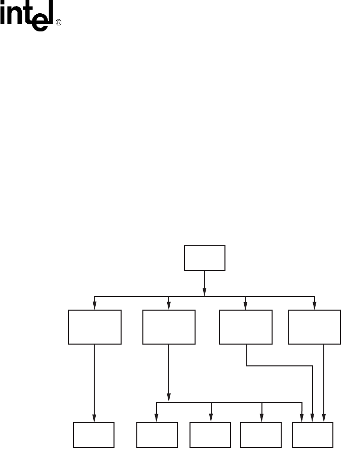
Voice API Programming Guide — June 2005 45
Call Progress Analysis
•positive answering machine detection (post-connect part of call progress analysis)
•fax tone detection (post-connect part of call progress analysis)
Figure 2 illustrates the components of basic call progress analysis. Figure 3 illustrates the
components of PerfectCall call progress analysis. These components can all operate
simultaneously.
In basic call progress analysis, cadence detection is the sole means of detecting a no ringback, busy,
or no answer. PerfectCall call progress analysis uses cadence detection plus frequency detection to
identify all of these signals plus fax machine tones. A connect can be detected through the
complementary methods of cadence detection, frequency detection, loop current detection, positive
voice detection, and positive answering machine detection.
Figure 2. Basic Call Progress Analysis Components
Incoming
Signal
Frequency
Detection
Cadence
Detection
Loop
Current
Detection
Positive
Voice
Detection
Intercept
(SIT) No
Ringback Busy No
Answer Connect
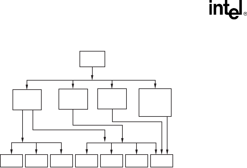
46 Voice API Programming Guide — June 2005
Call Progress Analysis
Figure 3. PerfectCall Call Progress Analysis Components
7.4 Using Call Progress Analysis on DM3 Boards
The following topics provide information on how to use call progress analysis on DM3 boards:
•Call Progress Analysis Rules on DM3 Boards
•Overview of Steps to Initiate Call Progress Analysis
•Setting Up Call Progress Analysis Parameters in DX_CAP
•Executing a Dial Function
•Determining the Outcome of a Call
•Obtaining Additional Call Outcome Information
7.4.1 Call Progress Analysis Rules on DM3 Boards
The following rules apply to the use of call progress analysis on DM3 boards:
•It is recommended that all applications use the Global Call API for call progress analysis on
DM3 boards. For more information, see the Global Call API Programming Guide. However,
for backward compatibility, applications that use ISDN protocols can still enable call progress
analysis using dx_dial( ).
•If you choose to use dx_dial( ) in ISDN applications, do not mix the use of the Global Call
API and the Voice API within a phase of call progress analysis (pre-connect or post-connect).
•If you use channel associated signaling (CAS) or analog protocols, the following rules apply:
–Pre-connect is typically provided by the protocol via the Global Call API.
–The dx_dial( ) function cannot be used for pre-connect.
–If post-connect is disabled in the protocol, then dx_dial( ) is available for post-connect.
Incoming
Signal
Frequency
Detection
Cadence
Detection
Loop
Current
Detection
Intercept
(SIT)
No
Ringback
Busy No
Answer Connect
Fax Tone
No
Dialtone
Positive
Voice or
Answering
Machine
Detection

Voice API Programming Guide — June 2005 47
Call Progress Analysis
Table 4 provides information on call progress analysis scenarios supported with the dx_dial( )
function. This method is available regardless of the protocol being used; however, some restrictions
apply when using DM3 CAS protocols. The restrictions are due to the fact that the voice capability
is shared between the network device and the voice channel during the call setup time. In particular,
to invoke dx_dial( ) under channel associated signaling (CAS), your application must wait for the
connected event.
Note: The information in this table also applies to DM3 analog products, which are considered to use
CAS protocols.
7.4.2 Overview of Steps to Initiate Call Progress Analysis
Review the information in Section 7.4.1, “Call Progress Analysis Rules on DM3 Boards”, on
page 46. If you choose to use the voice API for call progress analysis on DM3 boards, perform the
following procedure to initiate an outbound call with call progress analysis:
1. Set up the call analysis parameter structure (DX_CAP), which contains parameters to control
the operation of call progress analysis, such as positive voice detection and positive answering
machine detection.
2. Call dx_dial( ) to start call progress analysis during the desired phase of the call.
3. Use the ATDX_CPTERM( ) extended attribute function to determine the outcome of the call.
4. Obtain additional termination information as desired using extended attribute functions.
Each of these steps is described in more detail next. For a full description of the functions and data
structures described in this chapter, see the Voice API Library Reference.
Table 4. Call Progress Analysis Support with dx_dial( )
CPA Feature
dx_dial( )
support on
DM3
Comments
Busy Yes analog/CAS protocols: not supported
No ringback Yes analog/CAS protocols: not supported
SIT frequency detection Yes analog/CAS protocols: not supported
No answer Yes analog/CAS protocols: not supported
Cadence break Yes analog/CAS protocols: not supported
Loop current detection No
Dial tone detection No
Fax tone detection Yes analog/CAS protocols: wait for Global Call
GCEV_CONNECTED event
Positive Voice Detection (PVD) Yes analog/CAS protocols: wait for Global Call
GCEV_CONNECTED event
Positive Answering Machine
Detection (PAMD)
Yes analog/CAS protocols: wait for Global Call
GCEV_CONNECTED event

48 Voice API Programming Guide — June 2005
Call Progress Analysis
7.4.3 Setting Up Call Progress Analysis Parameters in DX_CAP
The call progress analysis parameters structure, DX_CAP, is used by dx_dial( ). It contains
parameters to control the operation of call progress analysis features, such as positive voice
detection (PVD) and positive answering machine detection (PAMD). To customize the parameters
for your environment, you must set up the DX_CAP structure before calling a dial function.
To set up the DX_CAP structure for call progress analysis:
1. Execute the dx_clrcap( ) function to clear the DX_CAP and initialize the parameters to 0. The
value 0 indicates that the default value will be used for that particular parameter. dx_dial( ) can
also be set to run with default call progress analysis parameter values, by specifying a NULL
pointer to the DX_CAP structure.
2. Set a DX_CAP parameter to another value if you do not want to use the default value. The
ca_intflg field (intercept mode flag) of DX_CAP enables and disables the following call
progress analysis components: SIT frequency detection, positive voice detection (PVD), and
positive answering machine detection (PAMD). Use one of the following values for the
ca_intflg field:
•DX_OPTDIS. Disables Special Information Tone (SIT) frequency detection, PAMD, and
PVD. This setting provides call progress without SIT frequency detection.
•DX_OPTNOCON. Enables SIT frequency detection and returns an “intercept”
immediately after detecting a valid frequency. This setting provides call progress with SIT
frequency detection.
•DX_PVDENABLE. Enables PVD and fax tone detection. Provides PVD call analysis
only (no call progress).
•DX_PVDOPTNOCON. Enables PVD, DX_OPTNOCON, and fax tone detection. This
setting provides call progress with SIT frequency detection and PVD call analysis.
•DX_PAMDENABLE. Enables PAMD, PVD, and fax tone detection. This setting provides
PAMD and PVD call analysis only (no call progress).
•DX_PAMDOPTEN. Enables PAMD, PVD, DX_OPTNOCON, and fax tone detection.
This setting provides full call progress and call analysis.
Note: DX_OPTEN and DX_PVDOPTEN are obsolete. Use DX_OPTNOCON and
DX_PVDOPTNOCON instead.
7.4.4 Executing a Dial Function
To use call progress analysis, call dx_dial( ) with the mode function argument set to DX_CALLP.
Termination of dialing with call progress analysis is indicated differently depending on whether the
function is running asynchronously or synchronously.
If running asynchronously, use Standard Runtime Library (SRL) event management functions to
determine when dialing with call progress analysis is complete (TDX_CALLP termination event).
If running synchronously, wait for the function to return a value greater than 0 to indicate
successful completion.

Voice API Programming Guide — June 2005 49
Call Progress Analysis
Notes: 1. On DM3 boards, dx_dial( ) cannot be used to start an outbound call; instead use the Global Call
API.
2. To issue dx_dial( ) without dialing digits, specify “ ” in the dialstrp argument.
7.4.5 Determining the Outcome of a Call
In asynchronous mode, once dx_dial( ) with call progress analysis has terminated, use the
extended attribute function ATDX_CPTERM( ) to determine the outcome of the call. (In
synchronous mode, dx_dial( ) returns the outcome of the call.) ATDX_CPTERM( ) will return
one of the following call progress analysis termination results:
CR_BUSY
Called line was busy.
CR_CEPT
Called line received operator intercept (SIT).
CR_CNCT
Called line was connected. Use ATDX_CONNTYPE( ) to return the connection type for a
completed call.
CR_ERROR
Call progress analysis error occurred. Use ATDX_CPERROR( ) to return the type of error.
CR_FAXTONE
Called line was answered by fax machine or modem.
CR_NOANS
Called line did not answer.
CR_NORB
No ringback on called line.
CR_STOPD
Call progress analysis stopped due to dx_stopch( ).
Figure 4 illustrates the possible outcomes of call progress analysis.
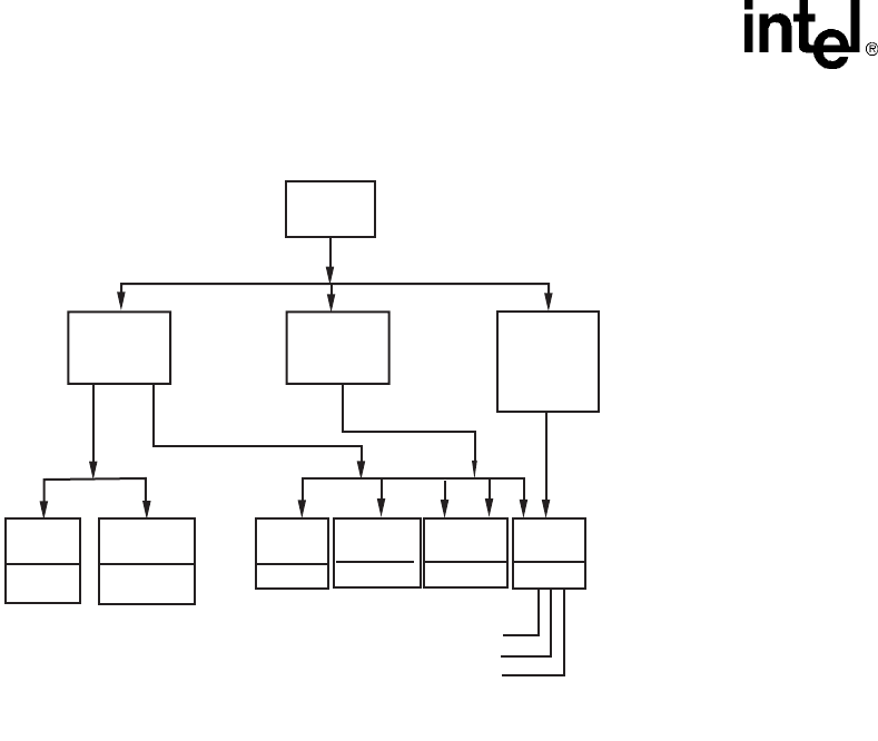
50 Voice API Programming Guide — June 2005
Call Progress Analysis
Figure 4. Call Outcomes for Call Progress Analysis (DM3)
7.4.6 Obtaining Additional Call Outcome Information
To obtain additional call progress analysis information, use the following extended attribute
functions:
ATDX_CPERROR( )
Returns call analysis error.
ATDX_CPTERM( )
Returns last call analysis termination reason.
ATDX_CONNTYPE( )
Returns connection type.
See each function reference description in the Voice API Library Reference for more information.
Note: These extended attribute functions do not return information about functionality that is not
supported on DM3 boards; for example, connection type CON_LPC and termination reason
CR_NODIALTONE.
Frequency
Detection
Cadence
Detection
Positive
Voice or
Answering
Machine
Detection
Incoming
Signal
Connect
Reason
Termination Reason: From ATDX_CPTERM( ).
Connect Reason: From ATDX_CONNTYPE( ).
CON_CAD
CON_PVD
CON_PAMD
Te r m i -
nation
Reason
Connect
CR_CNCT
No
Ringback
CR_NORB
Busy
CR_BUSY
Faxtone
CR_FAXTONE
Intercept
(SIT)
CR_CEPT
No
Answer
CR_NOANS

Voice API Programming Guide — June 2005 51
Call Progress Analysis
7.5 Call Progress Analysis Tone Detection on DM3
Boards
The following topics discuss tone detection used in call progress analysis on DM3 boards:
•Tone Detection Overview
•Types of Tones
•Ringback Detection
•Busy Tone Detection
•Fax or Modem Tone Detection
•SIT Frequency Detection
7.5.1 Tone Detection Overview
Call progress analysis uses a combination of cadence detection and frequency detection to identify
certain signals during the course of an outgoing call. Cadence detection identifies repeating
patterns of sound and silence, and frequency detection determines the pitch of the signal. Together,
the cadence and frequency of a signal make up its “tone definition”.
7.5.2 Types of Tones
Tone definitions are used to identify several kinds of signals.
The following defined tones and tone identifiers are provided by the voice library for DM3 boards.
Tone identifiers are returned by the ATDX_CRTNID( ) function.
TID_BUSY1
First signal busy
TID_BUSY2
Second signal busy
TID_DIAL_INTL
International dial tone
TID_DIAL_LCL
Local dial tone
TID_DISCONNECT
Disconnect tone (post-connect)
TID_FAX1
First fax or modem tone
TID_FAX2
Second fax or modem tone
TID_RNGBK1
Ringback (detected as single tone)

52 Voice API Programming Guide — June 2005
Call Progress Analysis
TID_RNGBK2
Ringback (detected as dual tone)
TID_SIT_ANY
Catch all (returned for a Special Information Tone sequence or SIT sequence that falls outside
the range of known default SIT sequences)
TID_SIT_INEFFECTIVE_OTHER or
TID_SIT_IO
Ineffective other SIT sequence
TID_SIT_NO_CIRCUIT or
TID_SIT_NC
No circuit found SIT sequence
TID_SIT_NO_CIRCUIT_INTERLATA or
TID_SIT_NC_INTERLATA
InterLATA no circuit found SIT sequence
TID_SIT_OPERATOR_INTERCEPT or
TID_SIT_IC
Operator intercept SIT sequence
TID_SIT_REORDER_TONE or
TID_SIT_RO
Reorder (system busy) SIT sequence
TID_SIT_REORDER_TONE_INTERLATA or
TID_SIT_RO_INTERLATA
InterLATA reorder (system busy) SIT sequence
TID_SIT_VACANT_CIRCUIT or
TID_SIT_VC
Vacant circuit SIT sequence
Some of these tone identifiers may be used as input to function calls to change the tone definitions.
For more information, see Section 7.8, “Modifying Default Call Progress Analysis Tone
Definitions on DM3 Boards”, on page 57.
7.5.3 Ringback Detection
Call progress analysis uses the tone definition for ringback to identify the first ringback signal of an
outgoing call. At the end of the first ringback (that is, normally, at the beginning of the second
ringback), a timer goes into effect. The system continues to identify ringback signals (but does not
count them). If a break occurs in the ringback cadence, the call is assumed to have been answered,
and call progress analysis terminates with the reason CR_CNCT (connect); the connection type
returned by the ATDX_CONNTYPE( ) function will be CON_CAD (cadence break).
However, if the timer expires before a connect is detected, then the call is deemed unanswered, and
call progress analysis terminates with the reason CR_NOANS.

Voice API Programming Guide — June 2005 53
Call Progress Analysis
To enable ringback detection, turn on SIT frequency detection in the DX_CAP ca_intflg field. For
details, see Section 7.4.3, “Setting Up Call Progress Analysis Parameters in DX_CAP”, on
page 48.
The following DX_CAP fields govern ringback behavior on DM3 boards:
ca_cnosig
Continuous No Signal: the maximum length of silence (no signal) allowed immediately after
the ca_stdely period (in 10 msec units). If this duration is exceeded, call progress analysis is
terminated with the reason CR_NORB (no ringback detected). Default value: 4000 (40
seconds).
ca_noanswer
No Answer: the length of time to wait after the first ringback before deciding that the call is
not answered (in 10 msec units). If this duration is exceeded, call progress analysis is
terminated with the reason CR_NOANS (no answer). Default value: 3000 (30 seconds).
7.5.4 Busy Tone Detection
Call progress analysis specifies two busy tones: TID_BUSY1 and TID_BUSY2. If either of them is
detected while frequency detection and cadence detection are active, then call progress is
terminated with the reason CR_BUSY. ATDX_CRTNID( ) identifies which busy tone was
detected.
To enable busy tone detection, turn on SIT frequency detection in the DX_CAP ca_intflg field. For
details, see Section 7.4.3, “Setting Up Call Progress Analysis Parameters in DX_CAP”, on
page 48.
7.5.5 Fax or Modem Tone Detection
Call progress analysis specifies two tones: TID_FAX1 and TID_FAX2. If either of these tones is
detected while frequency detection and cadence detection are active, then call progress is
terminated with the reason CR_FAXTONE. ATDX_CRTNID( ) identifies which fax or modem
tone was detected.
To enable fax or modem tone detection, use the ca_intflg field of the DX_CAP structure. For
details, see Section 7.4.3, “Setting Up Call Progress Analysis Parameters in DX_CAP”, on
page 48.
7.5.6 SIT Frequency Detection
Special Information Tone (SIT) frequency detection is a component of call progress analysis. On
DM3 boards, SIT sequences are defined as standard tone IDs.
To enable SIT frequency detection, use the ca_intflg field of the DX_CAP structure. For more
information, see Section 7.4.3, “Setting Up Call Progress Analysis Parameters in DX_CAP”, on
page 48.

54 Voice API Programming Guide — June 2005
Call Progress Analysis
Table 5 shows default tone definitions for SIT sequences used on DM3 boards. The values in the
“Freq.” column represent minimum and maximum values in Hz. “Time” refers to minimum and
maximum on time in 10 msec units; the maximum off time between each segment is 5 (or 50
msec). The repeat count is 1 for all SIT segments. N/A means “not applicable.”
The following considerations apply to SIT sequences on DM3 boards:
•A single tone proxy for the dual tone (also called twin tone) exists for each of the three
segments in a SIT sequence. The default definition for the minimum value and maximum
value (in Hz) is 0. For more information on this tone, see Section 7.8.4, “Rules for Using a
Single Tone Proxy for a Dual Tone”, on page 59.
•These tone IDs have aliases:
–TID_SIT_NO_CIRCUIT (TID_SIT_NC)
–TID_SIT_OPERATOR_INTERCEPT (TID_SIT_IC)
–TID_SIT_VACANT_CIRCUIT (TID_SIT_VC)
–TID_SIT_REORDER_TONE (TID_SIT_RO)
–TID_SIT_NO_CIRCUIT_INTERLATA (TID_SIT_NC_INTERLATA)
–TID_SIT_REORDER_TONE_INTERLATA (TID_SIT_RO_INTERLATA)
–TID_SIT_INEFFECTIVE_OTHER (TID_SIT_IO)
•Default SIT definitions can be modified, except for the following SIT sequences: TID_SIT_
ANY, TID_SIT_IO, TID_SIT_NC_INTERLATA, and TID_SIT_RO_INTERLATA. For more
information, see Section 7.8, “Modifying Default Call Progress Analysis Tone Definitions on
DM3 Boards”, on page 57.
•For TID_SIT_ANY, the frequency and time of the first and second segments are open; that is,
they are ignored. Only the frequency of the third segment is relevant. This catch-all SIT
sequence definition is intended to cover SIT sequences that fall outside the range of the
defined SIT sequences.
Table 5. Special Information Tone Sequences (DM3)
SIT 1st Segment 2nd Segment 3rd Segment
Tone ID Description Freq. Time Freq. Time Freq. Time
TID_SIT_NC No Circuit Found 950/1020 32/45 1400/1450 32/45 1740/1850 N/A
TID_SIT_IC Operator
Intercept
874/955 15/30 1310/1430 15/30 1740/1850 N/A
TID_SIT_VC Vacant Circuit 950/1020 32/45 1310/1430 15/30 1740/1850 N/A
TID_SIT_RO Reorder
(system busy)
874/955 15/30 1400/1450 32/45 1740/1850 N/A
TID_SIT_NC_
INTERLATA
InterLATA No
Circuit Found
874/955 32/45 1310/1430 32/45 1740/1850 N/A
TID_SIT_RO_
INTERLATA
InterLATA
Reorder (system
busy)
950/1020 15/30 1310/1430 32/45 1740/1850 N/A
TID_SIT_IO Ineffective Other 874/955 32/45 1400/1450 15/30 1740/1850 N/A
TID_SIT_ANY Catch all tone
definition
Open Open Open Open 1725/1825 N/A

Voice API Programming Guide — June 2005 55
Call Progress Analysis
7.6 Media Tone Detection on DM3 Boards
Media tone detection in call progress analysis is discussed in the following topics:
•Positive Voice Detection (PVD)
•Positive Answering Machine Detection (PAMD)
7.6.1 Positive Voice Detection (PVD)
Positive voice detection (PVD) can detect when a call has been answered by determining whether
an audio signal is present that has the characteristics of a live or recorded human voice. This
provides a very precise method for identifying when a connect occurs.
The ca_intflg field in DX_CAP enables/disables PVD. For information on enabling PVD, see
Section 7.4.3, “Setting Up Call Progress Analysis Parameters in DX_CAP”, on page 48.
PVD is especially useful in those situations where no other method of answer supervision is
available, and where the cadence is not clearly broken for cadence detection to identify a connect
(for example, when the nonsilence of the cadence is immediately followed by the nonsilence of
speech).
If the ATDX_CONNTYPE( ) function returns CON_PVD, the connect was due to positive voice
detection.
7.6.2 Positive Answering Machine Detection (PAMD)
Whenever PAMD is enabled, positive voice detection (PVD) is also enabled.
The ca_intflg field in DX_CAP enables/disables PAMD and PVD. For information on enabling
PAMD, see Section 7.4.3, “Setting Up Call Progress Analysis Parameters in DX_CAP”, on
page 48.
When enabled, detection of an answering machine will result in the termination of call analysis
with the reason CR_CNCT (connected); the connection type returned by the
ATDX_CONNTYPE( ) function will be CON_PAMD.
The following DX_CAP fields govern positive answering machine detection:
ca_pamd_spdval
PAMD Speed Value: To distinguish between a greeting by a live human and one by an
answering machine, use one of the following settings:
•PAMD_FULL – look at the greeting (long method). The long method looks at the full
greeting to determine whether it came from a human or a machine. Using PAMD_FULL
gives a very accurate determination; however, in situations where a fast decision is more
important than accuracy, PAMD_QUICK might be preferred.
•PAMD_QUICK – look at connect only (quick method). The quick method examines only
the events surrounding the connect time and makes a rapid judgment as to whether or not
an answering machine is involved.
•PAMD_ACCU – look at the greeting (long method) and use the most accuracy for
detecting an answering machine. This setting provides the most accurate evaluation. It

56 Voice API Programming Guide — June 2005
Call Progress Analysis
detects live voice as accurately as PAMD_FULL but is more accurate than PAMD_FULL
(although slightly slower) in detecting an answering machine. Use the setting
PAMD_ACCU when accuracy is more important than speed.
Default value (DM3 boards): PAMD_ACCU
The recommended setting for the call analysis parameter structure (DX_CAP)
ca_pamd_spdval field is PAMD_ACCU.
ca_pamd_failtime
maximum time to wait for positive answering machine detection or positive voice detection
after a cadence break. Default Value: 400 (in 10 msec units).
7.7 Default Call Progress Analysis Tone Definitions on
DM3 Boards
Table 6 provides the range of values for default tone definitions for DM3 boards. These default
tone definitions are used in call progress analysis. Amplitudes are given in dBm, frequencies in Hz,
and duration in 10 msec units. A dash in a table cell means not applicable.
Notes: 1. On DM3 boards, voice API functions are provided to manipulate the tone definitions in this table
(see Section 7.8, “Modifying Default Call Progress Analysis Tone Definitions on DM3 Boards”,
on page 57). However, not all the functionality provided by these tones is available through the
voice API. You may need to use the Global Call API to access the functionality, for example, in
the case of dial tone detection and disconnect tone detection.
2. An On Time maximum value of 0 indicates that this is a continuous tone. For example,
TID_DIAL_LCL has an On Time range of 10 to 0. This means that the tone is on for 100 msecs.
The minimum requirement for detecting a tone is that it must be continuous for at least 100
msecs (10 in 10 msec units) after it is detected.
3. A single tone proxy for a dual tone (twin tone) can help improve the accuracy of dual tone
detection in some cases. For more information, see Section 7.8.4, “Rules for Using a Single Tone
Proxy for a Dual Tone”, on page 59.

Voice API Programming Guide — June 2005 57
Call Progress Analysis
7.8 Modifying Default Call Progress Analysis Tone
Definitions on DM3 Boards
On DM3 boards, call progress analysis tones are maintained in the firmware on a physical board
level and are board-specific. More information on tone definitions is provided in the following
topics:
•API Functions for Manipulating Tone Definitions
•TONE_DATA Data Structure
•Rules for Modifying a Tone Definition on DM3 Boards
•Rules for Using a Single Tone Proxy for a Dual Tone
•Steps to Modify a Tone Definition on DM3 Boards
7.8.1 API Functions for Manipulating Tone Definitions
The following voice API functions are used to manipulate the default tone definitions shown in
Table 6, “Default Call Progress Analysis Tone Definitions (DM3)”, on page 57 and some, but not
all, of the default tone definitions shown in Table 5, “Special Information Tone Sequences (DM3)”,
on page 54.
Note: Default SIT definitions can be modified, except for the following SIT sequences: TID_SIT_ ANY,
TID_SIT_IO, TID_SIT_NC_INTERLATA, and TID_SIT_RO_INTERLATA.
dx_querytone( )
gets tone information for a specific call progress tone
Table 6. Default Call Progress Analysis Tone Definitions (DM3)
Tone ID Freq1
(in Hz)
Freq2
(in Hz)
On Time
(in 10 msec)
Off Time
(in 10 msec) Reps Twin Tone
Freq (Hz)
TID_BUSY1 450 - 510 590 - 650 30 - 100 30 - 100 2 0
TID_BUSY2 450 - 510 590 - 650 10 - 40 10 - 40 2 0
TID_DIAL_INTL 300 - 380 400 - 480 100 - 0 - 1 300 - 480
TID_DIAL_LCL 300 - 380 400 - 480 10 - 0 - 1 0
TID_DISCONNECT 360 - 410 430 - 440 30 - 60 30 - 60 1 360 - 440
TID_FAX1 1050 - 1150 - 10 - 60 - 1 -
TID_FAX2 2000 - 2300 - 10 - 0 - 1 -
TID_RNGBK1 350 - 550 350 - 550 75 - 300 0 - 800 1 350 - 550
TID_RNGBK2
(segment 0)
350 - 550 350 - 550 20 - 100 20 - 100 1 350 - 550
TID_RNGBK2
(segment 1)
350 - 550 350 - 550 20 - 100 100 - 600 1 350 - 550

58 Voice API Programming Guide — June 2005
Call Progress Analysis
dx_deletetone( )
deletes a specific call progress tone
dx_createtone( )
creates a new tone definition for a specific call progress tone
7.8.2 TONE_DATA Data Structure
The TONE_DATA structure contains tone information for a specific call progress tone. This
structure contains a nested array of TONE_SEG substructures. A maximum of six TONE_SEG
substructures can be specified. The TONE_DATA structure specifies the following key
information:
TONE_SEG.structver
Specifies the version of the TONE_SEG structure. Used to ensure that an application is binary
compatible with future changes to this data structure.
TONE_SEG.tn_dflag
Specifies whether the tone is dual tone or single tone. Values are 1 for dual tone and 0 for
single tone.
TONE_SEG.tn1_min
Specifies the minimum frequency in Hz for tone 1.
TONE_SEG.tn1_max
Specifies the maximum frequency in Hz for tone 1.
TONE_SEG.tn2_min
Specifies the minimum frequency in Hz for tone 2.
TONE_SEG.tn2_max
Specifies the maximum frequency in Hz for tone 2.
TONE_SEG.tn_twinmin
Specifies the minimum frequency in Hz of the single tone proxy for the dual tone.
TONE_SEG.tn_twinmax
Specifies the maximum frequency in Hz of the single tone proxy for the dual tone.
TONE_SEG.tnon_min
Specifies the debounce minimum ON time in 10 msec units.
TONE_SEG.tnon_max
Specifies the debounce maximum ON time in 10 msec units.
TONE_SEG.tnoff_min
Specifies the debounce minimum OFF time in 10 msec units.
TONE_SEG.tnoff_max
Specifies the debounce maximum OFF time in 10 msec units.
TONE_DATA.structver
Specifies the version of the TONE_DATA structure. Used to ensure that an application is
binary compatible with future changes to this data structure.
TONE_DATA.tn_rep_cnt
Specifies the debounce rep count.

Voice API Programming Guide — June 2005 59
Call Progress Analysis
TONE_DATA.numofseg
Specifies the number of segments for a multi-segment tone.
7.8.3 Rules for Modifying a Tone Definition on DM3 Boards
Consider the following rules and guidelines for modifying default tone definitions on DM3 boards
using the voice API library:
•Yo u m u s t i ss u e dx_querytone( ), dx_deletetone( ), and dx_createtone( ) in this order, one
tone at a time, for each tone definition to be modified.
•Attempting to create a new tone definition before deleting the current call progress tone will
result in an EDX_TNQUERYDELETE error.
•When dx_querytone( ), dx_deletetone( ), or dx_createtone( ) is issued in asynchronous
mode and is immediately followed by another similar call prior to completion of the previous
call on the same device, the subsequent call will fail with device busy.
•Only default call progress analysis tones and SIT sequences are supported for these three
functions. For a list of these tones, see Table 5, “Special Information Tone Sequences (DM3)”,
on page 54 and Table 6, “Default Call Progress Analysis Tone Definitions (DM3)”, on
page 57.
•These three voice API functions are provided to manipulate the call progress analysis tone
definitions. However, not all the functionality provided by these tones is available through the
voice API. You may need to use the Global Call API to access the functionality, for example,
in the case of dial tone detection and disconnect tone detection.
•If the application deletes all the default call progress analysis tones in a particular set (where a
set is defined as busy tones, dial tones, ringback tones, fax tones, disconnect tone, and special
information tones), the set itself is deleted from the board and call progress analysis cannot be
performed successfully. Therefore, you must have at least one tone defined in each tone set in
order for call progress analysis to perform successfully.
Note: The Learn Mode API and Tone Set File (TSF) API provide a more comprehensive way to manage
call progress tones, in particular the unique call progress tones produced by PBXs, key systems,
and PSTNs. Applications can learn tone characteristics using the Learn Mode API. Information on
several different tones forms one tone set. Tone sets can be written to a tone set file using the Tone
Set File API. For more information, see the Learn Mode and Tone Set File API Software Reference.
7.8.4 Rules for Using a Single Tone Proxy for a Dual Tone
A single tone proxy (also called a twin tone) acts as a proxy for a dual tone. A single tone proxy
can be defined when you run into difficulty detecting a dual tone. This situation can arise when the
two frequencies of the dual tone are close together, are very short tones, or are even multiples of
each other. In these cases, the dual tone might be detected as a single tone. A single tone proxy can
help improve the detection of the dual tone by providing an additional tone definition.
The TONE_SEG.tn_twinmin field defines the minimum frequency of the tone and
TONE_SEG.tn_twinmax field defines the maximum frequency of the tone.

60 Voice API Programming Guide — June 2005
Call Progress Analysis
Consider the following guidelines when creating a single tone proxy:
•It is recommended that you add at least 60 Hz to the top of the dual tone range and subtract at
least 60 Hz from the bottom of the dual tone range. For example:
Freq1 (Hz): 400 - 500
Freq 2 (Hz): 600 - 700
Twin tone freq (Hz): 340 - 760
•Before using the TONE_DATA structure in a function call, set any unused fields in the
structure to zero to prevent possible corruption of data in the allocated memory space. This
guideline is applicable to unused fields in any data structure.
7.8.5 Steps to Modify a Tone Definition on DM3 Boards
To modify a default tone definition on DM3 boards using the voice API library, follow these steps:
Note: This procedure assumes that you have already opened the physical board device handle in your
application. To get the physical board name in the form brdBn, use the
SRLGetPhysicalBoardName( ) function. This function and other device mapper functions return
information about the structure of the system. For more information, see the Standard Runtime
Library API Library Reference.
1. Get the tone information for the call progress tone to be modified using dx_querytone( ).
After the function completes successfully, the relevant tone information is contained in the
TONE_DATA structure.
2. Delete the current call progress tone using dx_deletetone( ) before creating a new tone
definition.
3. Create a new tone definition for the call progress tone using dx_createtone( ). Specify the new
tone information in the TONE_DATA structure.
4. Repeat steps 1-3 in this order for each tone to be modified.
7.9 Call Progress Analysis Errors
If ATDX_CPTERM( ) returns CR_ERROR, you can use ATDX_CPERROR( ) to determine the
call progress analysis error that occurred. For details on these functions, see the Voice API Library
Reference.
7.10 Using Call Progress Analysis on Springware Boards
The following topics provide information on how to use call progress analysis when making an
outbound call:
•Overview of Steps to Initiate Call Progress Analysis
•Setting Up Call Progress Analysis Features in DX_CAP
•Enabling Call Progress Analysis
•Executing a Dial Function

Voice API Programming Guide — June 2005 61
Call Progress Analysis
•Determining the Outcome of a Call
•Obtaining Additional Call Outcome Information
7.10.1 Overview of Steps to Initiate Call Progress Analysis
Perform the following procedure to initiate an outbound call with call progress analysis:
1. Set up the call analysis parameter structure (DX_CAP), which contains parameters to control
the operation of call progress analysis, such as frequency detection, cadence detection, loop
current, positive voice detection, and positive answering machine detection.
2. On Springware boards, enable call progress analysis on a specified channel using
dx_initcallp( ). Modify tone definitions as appropriate.
3. Call dx_dial( ) to start an outbound call.
4. Use the ATDX_CPTERM( ) extended attribute function to determine the outcome of the call.
5. Obtain additional termination, frequency, or cadence information (such as the length of the
salutation) as desired using extended attribute functions.
Each of these steps is described in more detail next. For a full description of the functions and data
structures described in this chapter, see the Voice API Library Reference.
7.10.2 Setting Up Call Progress Analysis Features in DX_CAP
The call progress analysis parameters structure, DX_CAP, is used by dx_dial( ). It contains
parameters to control the operation of call progress analysis features, such as frequency detection,
positive voice detection (PVD), and positive answering machine detection (PAMD).
To customize the parameters for your environment, you must set up the call progress analysis
parameter structure before calling a dial function.
To set up the DX_CAP structure for call progress analysis:
1. Execute the dx_clrcap( ) function to clear the DX_CAP and initialize the parameters to 0. The
value 0 indicates that the default value will be used for that particular parameter. dx_dial( ) can
also be set to run with default call progress analysis parameter values, by specifying a NULL
pointer to the DX_CAP structure.
2. Set a DX_CAP parameter to another value if you do not want to use the default value. The
ca_intflg field (intercept mode flag) of DX_CAP enables and disables the following call
progress analysis components: SIT frequency detection, positive voice detection (PVD), and
positive answering machine detection (PAMD). Use one of the following values for the
ca_intflg field:
•DX_OPTDIS. Disables Special Information Tone (SIT) frequency detection, PAMD, and
PVD.
•DX_OPTNOCON. Enables SIT frequency detection and returns an “intercept”
immediately after detecting a valid frequency.
•DX_PVDENABLE. Enables PVD and fax tone detection.
•DX_PVDOPTNOCON. Enables PVD, DX_OPTNOCON, and fax tone detection.

62 Voice API Programming Guide — June 2005
Call Progress Analysis
•DX_PAMDENABLE. Enables PAMD, PVD, and fax tone detection.
•DX_PAMDOPTEN. Enables PAMD, PVD, DX_OPTNOCON, and fax tone detection.
Note: DX_OPTEN and DX_PVDOPTEN are obsolete. Use DX_OPTNOCON and
DX_PVDOPTNOCON instead.
For more information on adjusting DX_CAP parameters, see Section 7.11, “Call Progress Analysis
Tone Detection on Springware Boards”, on page 65, Section 7.12, “Media Tone Detection on
Springware Boards”, on page 69, and Section 7.15, “SIT Frequency Detection (Springware Only)”,
on page 72.
7.10.3 Enabling Call Progress Analysis
Call progress analysis is activated on a per-channel basis. On Springware boards, initiate call
progress analysis using the dx_initcallp( ) function.
On Springware boards, to enable call progress analysis on a specified channel, perform the
following steps. This procedure needs to be followed only once per channel; thereafter, any
outgoing calls made using a dial function will benefit from call progress analysis.
1. Make any desired modifications to the default dial tone, busy tone, fax tone, and ringback
signal definitions using the dx_chgfreq( ), dx_chgdur( ), and dx_chgrepcnt( ) functions. For
more information, see Section 7.14, “Modifying Default Call Progress Analysis Tone
Definitions on Springware Boards”, on page 71.
2. Call dx_deltones( ) to clear all tone templates remaining on the channel. Note that this
function deletes all global tone definition (GTD) tones for the given channel, and not just those
involved with call progress analysis.
3. Execute the dx_initcallp( ) function to activate call progress analysis. Call progress analysis
stays active until dx_deltones( ) is called.
The dx_initcallp( ) function initializes call progress analysis on the specified channel using the
current tone definitions. Once the channel is initialized with these tone definitions, this
initialization cannot be altered. The only way to change the tone definitions in effect for a given
channel is to issue a dx_deltones( ) call for that channel, then invoke another dx_initcallp( ) with
different tone definitions.
7.10.4 Executing a Dial Function
To use call progress analysis, call dx_dial( ) with the mode function argument set to DX_CALLP.
Termination of dialing with call progress analysis is indicated differently depending on whether the
function is running asynchronously or synchronously.
If running asynchronously, use Standard Runtime Library (SRL) Event Management functions to
determine when dialing with call progress analysis is complete (TDX_CALLP termination event).
If running synchronously, wait for the function to return a value greater than 0 to indicate
successful completion.

Voice API Programming Guide — June 2005 63
Call Progress Analysis
7.10.5 Determining the Outcome of a Call
In asynchronous mode, once dx_dial( ) with call progress analysis has terminated, use the
extended attribute function ATDX_CPTERM( ) to determine the outcome of the call. (In
synchronous mode, dx_dial( ) returns the outcome of the call.) ATDX_CPTERM( ) will return
one of the following call progress analysis termination results:
CR_BUSY
Called line was busy.
CR_CEPT
Called line received operator intercept (SIT). Extended attribute functions provide information
on detected frequencies and duration.
CR_CNCT
Called line was connected. Use ATDX_CONNTYPE( ) to return the connection type for a
completed call.
CR_ERROR
Call progress analysis error occurred. Use ATDX_CPERROR( ) to return the type of error.
CR_FAXTONE
Called line was answered by fax machine or modem.
CR_NOANS
Called line did not answer.
CR_NODIALTONE
Timeout occurred while waiting for dial tone.
CR_NORB
No ringback on called line.
CR_STOPD
Call progress analysis stopped due to dx_stopch( ).
Figure 5 illustrates the possible outcomes of call progress analysis on Springware boards.
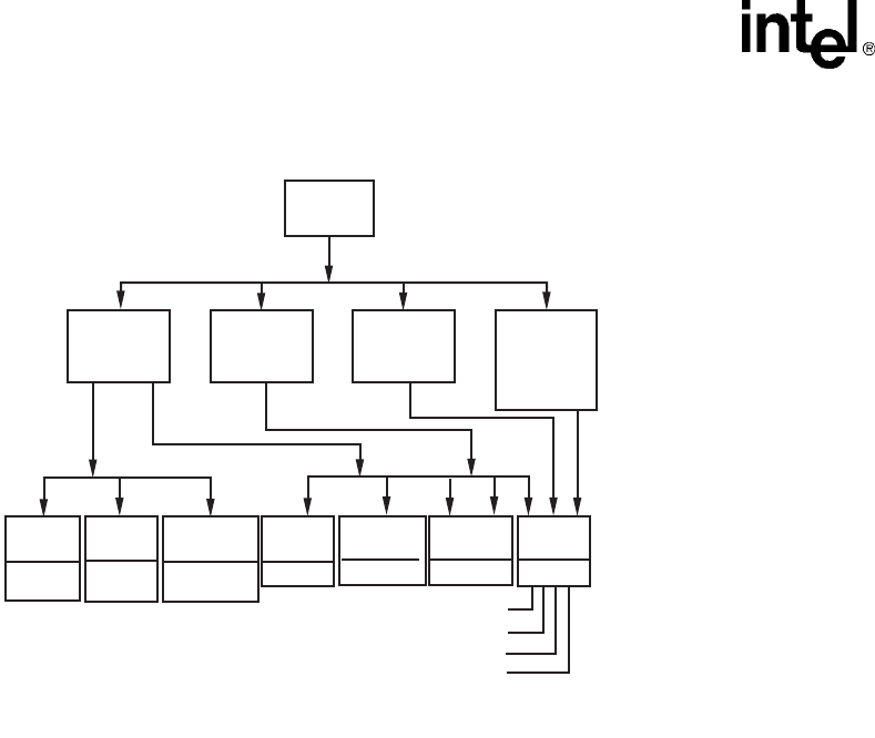
64 Voice API Programming Guide — June 2005
Call Progress Analysis
Figure 5. Call Outcomes for Call Progress Analysis (Springware)
7.10.6 Obtaining Additional Call Outcome Information
To obtain additional call progress analysis information, use the following extended attribute
functions:
ATDX_ANSRSIZ( )
Returns duration of answer.
ATDX_CPERROR( )
Returns call analysis error.
ATDX_CPTERM( )
Returns last call analysis termination.
ATDX_CONNTYPE( )
Returns connection type
ATDX_CRTNID( )
Returns the identifier of the tone that caused the most recent call progress analysis termination.
ATDX_DTNFAIL( )
Returns the dial tone character that indicates which dial tone call progress analysis failed to
detect.
ATDX_FRQDUR( )
Returns duration of first frequency detected.
ATDX_FRQDUR2( )
Returns duration of second frequency detected.
Frequency
Detection
Cadence
Detection
Loop
Current
Detection
Positive
Voice or
Answering
Machine
Detection
Incoming
Signal
Connect
Reason
Termination Reason: From ATDX_CPTERM( ).
Connect Reason: From ATDX_CONNTYPE( ).
CR_CAD
CON_LPC
CON_PVD
CON_PAMD
Termination
Reason
Connect
CR_CNCT
No
Ringback
CR_NORB
Busy
CR_BUSY
Faxtone
CR_FAXTONE
Intercept
(SIT)
CR_CEPT
No
Dialtone
CR_NO-
DIALTONE
No
Answer
CR_NOANS

Voice API Programming Guide — June 2005 65
Call Progress Analysis
ATDX_FRQDUR3( )
Returns duration of third frequency detected.
ATDX_FRQHZ( )
Returns frequency detected in Hz of first detected tone.
ATDX_FRQHZ2( )
Returns frequency of second detected tone.
ATDX_FRQHZ3( )
Returns frequency of third detected tone.
ATDX_LONGLOW( )
Returns duration of longer silence.
ATDX_FRQOUT( )
Returns percent of frequency out of bounds.
ATDX_SHORTLO( )
Returns duration of shorter silence.
ATDX_SIZEHI( )
Returns duration of non-silence.
See each function reference description in the Voice API Library Reference for more information.
For a discussion of how frequency and cadence information returned by these extended attribute
functions relate to the DX_CAP parameters, see Section 7.12, “Media Tone Detection on
Springware Boards”, on page 69 and Section 7.15, “SIT Frequency Detection (Springware Only)”,
on page 72.
7.11 Call Progress Analysis Tone Detection on
Springware Boards
Tone detection in PerfectCall call progress analysis differs from the one in basic call progress
analysis. The following topics discuss tone detection used in PerfectCall call progress analysis on
Springware boards:
•Tone Detection Overview
•Types of Tones
•Dial Tone Detection
•Ringback Detection
•Busy Tone Detection
•Fax or Modem Tone Detection
•Loop Current Detection

66 Voice API Programming Guide — June 2005
Call Progress Analysis
7.11.1 Tone Detection Overview
PerfectCall call progress analysis uses a combination of cadence detection and frequency detection
to identify certain signals during the course of an outgoing call. Cadence detection identifies
repeating patterns of sound and silence, and frequency detection determines the pitch of the signal.
Together, the cadence and frequency of a signal make up its “tone definition”.
Unlike basic call progress analysis, which uses fields in the DX_CAP structure to store signal
cadence information, PerfectCall call progress analysis uses tone definitions which are contained in
the voice driver itself. Functions are available to modify these default tone definitions.
7.11.2 Types of Tones
Tone definitions are used to identify several kinds of signals.
The following defined tones and tone identifiers are provided by the voice library on Springware
boards. Tone identifiers are returned by the ATDX_CRTNID( ) function.
TID_BUSY1
Busy signal
TID_BUSY2
Alternate busy signal
TID_DIAL_INTL
International dial tone
TID_DIAL_LCL
Local dial tone
TID_DIAL_XTRA
Special (extra) dial tone
TID_FAX1
CNG (calling) fax tone or modem tone
TID_FAX2
CED (called station) fax tone or modem tone
TID_RNGBK1
Ringback
TID_RNGBK2
Ringback
The tone identifiers are used as input to function calls to change the tone definitions. For more
information, see Section 7.14, “Modifying Default Call Progress Analysis Tone Definitions on
Springware Boards”, on page 71.

Voice API Programming Guide — June 2005 67
Call Progress Analysis
7.11.3 Dial Tone Detection
Wherever call progress analysis is in effect, a dial string for an outgoing call may specify special
ASCII characters that instruct the system to wait for a certain kind of dial tone. The following
additional special characters may appear in a dial string:
L
wait for a local dial tone
I
wait for an international dial tone
X
wait for a special (“extra”) dial tone
The tone definitions for each of these dial tones is set for each channel at the time of the
dx_initcallp( ) function. In addition, the following DX_CAP fields identify how long to wait for a
dial tone, and how long the dial tone must remain stable.
ca_dtn_pres
Dial Tone Present: the length of time that the dial tone must be continuously present (in 10
msec units). If a dial tone is present for this amount of time, dialing of the dial string proceeds.
Default value: 100 (one second).
ca_dtn_npres
Dial Tone Not Present: the length of time to wait before declaring the dial tone not present (in
10 msec units). If a dial tone of sufficient length (ca_dtn_pres) is not found within this period
of time, call progress analysis terminates with the reason CR_NODIALTONE. The dial tone
character (L, I, or X) for the missing dial tone can be obtained using ATDX_DTNFAIL( ).
Default value: 300 (three seconds).
ca_dtn_deboff
Dial Tone Debounce: the maximum duration of a break in an otherwise continuous dial tone
before it is considered invalid (in 10 msec units). This parameter is used for ignoring short
drops in dial tone. If a drop longer than ca_dtn_deboff occurs, then dial tone is no longer
considered present, and another dial tone must begin and be continuous for ca_dtn_pres.
Default value: 10 (100 msec).
7.11.4 Ringback Detection
Call progress analysis uses the tone definition for ringback to identify the first ringback signal of an
outgoing call. At the end of the first ringback (that is, normally, at the beginning of the second
ringback), a timer goes into effect. The system continues to identify ringback signals (but does not
count them). If a break occurs in the ringback cadence, the call is assumed to have been answered,
and call progress analysis terminates with the reason CR_CNCT (connect); the connection type
returned by the ATDX_CONNTYPE( ) function will be CON_CAD (cadence break).
However, if the timer expires before a connect is detected, then the call is deemed unanswered, and
call progress analysis terminates with the reason CR_NOANS.
To enable ringback detection, turn on SIT frequency detection in the DX_CAP ca_intflg field. For
details, see Section 7.10.2, “Setting Up Call Progress Analysis Features in DX_CAP”, on page 61.

68 Voice API Programming Guide — June 2005
Call Progress Analysis
The following DX_CAP fields govern ringback behavior:
ca_stdely
Start Delay: the delay after dialing has been completed before starting cadence detection,
frequency detection, and positive voice detection (in 10 msec units). Default: 25 (0.25
seconds).
ca_cnosig
Continuous No Signal: the maximum length of silence (no signal) allowed immediately after
the ca_stdely period (in 10 msec units). If this duration is exceeded, call progress analysis is
terminated with the reason CR_NORB (no ringback detected). Default value: 4000 (40
seconds).
ca_noanswer
No Answer: the length of time to wait after the first ringback before deciding that the call is
not answered (in 10 msec units). If this duration is exceeded, call progress analysis is
terminated with the reason CR_NOANS (no answer). Default value: 3000 (30 seconds).
ca_maxintering
Maximum Inter-ring: the maximum length of time to wait between consecutive ringback
signals (in 10 msec units). If this duration is exceeded, call progress analysis is terminated with
the reason CR_CNCT (connected). Default value: 800 (8 seconds).
7.11.5 Busy Tone Detection
Call progress analysis specifies two busy tones: TID_BUSY1 and TID_BUSY2. If either of them is
detected while frequency detection and cadence detection are active, then call progress is
terminated with the reason CR_BUSY. ATDX_CRTNID( ) identifies which busy tone was
detected.
To enable busy tone detection, turn on SIT frequency detection in the DX_CAP ca_intflg field. For
details, see Section 7.10.2, “Setting Up Call Progress Analysis Features in DX_CAP”, on page 61.
7.11.6 Fax or Modem Tone Detection
Two tones are defined: TID_FAX1 and TID_FAX2. If either of these tones is detected while
frequency detection and cadence detection are active, then call progress is terminated with the
reason CR_FAXTONE. ATDX_CRTNID( ) identifies which fax or modem tone was detected.
To enable fax or modem tone detection, turn on SIT frequency detection in the DX_CAP ca_intflg
field. For details, see Section 7.10.2, “Setting Up Call Progress Analysis Features in DX_CAP”, on
page 61.
7.11.7 Loop Current Detection
The dx_dial( ) function does not support loop current detection on DM3 boards.

Voice API Programming Guide — June 2005 69
Call Progress Analysis
Some telephone systems return a momentary drop in loop current when a connection has been
established (answer supervision). Loop current detection returns a connect when a transient loop
current drop is detected.
In some environments, including most PBXs, answer supervision is not provided. In these
environments, Loop current detection will not function. Check with your Central Office or PBX
supplier to see if answer supervision based on loop current changes is available.
In some cases, the application may receive one or more transient loop current drops before an
actual connection occurs. This is particularly true when dialing long-distance numbers, when the
call may be routed through several different switches. Any one of these switches may be capable of
generating a momentary drop in loop current.
To disable loop current detection, set DX_CAP ca_lcdly to -1.
Note: For applications that use loop current reversal to signal a disconnect, it is recommended that
DXBD_MINLCOFF be set to 2 to prevent Loop Current On and Loop Current Off from being
reported instead of Loop Current Reversal.
7.11.7.1 Loop Current Detection Parameters Affecting a Connect
To prevent detecting a connect prematurely or falsely due to a spurious loop current drop, you can
delay the start of loop current detection by using the parameter ca_lcdly.
Loop current detection returns a connect after detecting a loop current drop. To allow the person
who answered the phone to say “hello” before the application proceeds, you can delay the return of
the connect by using the parameter ca_lcdly1.
ca_lcdly
Loop Current Delay: the delay after dialing has been completed and before beginning Loop
Current Detection. To disable loop current detection, set to -1. Default: 400 (10 msec units).
ca_lcdly1
Loop Current Delay 1: the delay after loop current detection detects a transient drop in loop
current and before call progress analysis returns a connect to the application. Default: 10 (10
msec units).
If the ATDX_CONNTYPE( ) function returns CON_LPC, the connect was due to loop current
detection.
Note: When a connect is detected through positive voice detection or loop current detection, the
DX_CAP parameters ca_hedge, ca_ansrdgl, and ca_maxansr are ignored.
7.12 Media Tone Detection on Springware Boards
Media tone detection in call progress analysis is discussed in the following topics:
•Positive Voice Detection (PVD)
•Positive Answering Machine Detection (PAMD)

70 Voice API Programming Guide — June 2005
Call Progress Analysis
7.12.1 Positive Voice Detection (PVD)
Positive voice detection (PVD) can detect when a call has been answered by determining whether
an audio signal is present that has the characteristics of a live or recorded human voice. This
provides a very precise method for identifying when a connect occurs.
The ca_intflg field in DX_CAP enables/disables PVD. For information on enabling PVD, see
Section 7.10.2, “Setting Up Call Progress Analysis Features in DX_CAP”, on page 61.
PVD is especially useful in those situations where answer supervision is not available for loop
current detection to identify a connect, and where the cadence is not clearly broken for cadence
detection to identify a connect (for example, when the nonsilence of the cadence is immediately
followed by the nonsilence of speech).
If the ATDX_CONNTYPE( ) function returns CON_PVD, the connect was due to positive voice
detection.
7.12.2 Positive Answering Machine Detection (PAMD)
Whenever PAMD is enabled, positive voice detection (PVD) is also enabled.
The ca_intflg field in DX_CAP enables/disables PAMD and PVD. For information on enabling
PAMD, see Section 7.10.2, “Setting Up Call Progress Analysis Features in DX_CAP”, on page 61.
When enabled, detection of an answering machine will result in the termination of call analysis
with the reason CR_CNCT (connected); the connection type returned by the
ATDX_CONNTYPE( ) function will be CON_PAMD.
The following DX_CAP fields govern positive answering machine detection:
ca_pamd_spdval
PAMD Speed Value: To distinguish between a greeting by a live human and one by an
answering machine, use one of the following settings:
•PAMD_FULL – look at the greeting (long method). The long method looks at the full
greeting to determine whether it came from a human or a machine. Using PAMD_FULL
gives a very accurate determination; however, in situations where a fast decision is more
important than accuracy, PAMD_QUICK might be preferred.
•PAMD_QUICK – look at connect only (quick method). The quick method examines only
the events surrounding the connect time and makes a rapid judgment as to whether or not
an answering machine is involved.
•PAMD_ACCU – look at the greeting (long method) and use the most accuracy for
detecting an answering machine. This setting provides the most accurate evaluation. It
detects live voice as accurately as PAMD_FULL but is more accurate than PAMD_FULL
(although slightly slower) in detecting an answering machine. Use the setting
PAMD_ACCU when accuracy is more important than speed.
Default value (Springware boards): PAMD_FULL
The recommended setting for the call analysis parameter structure (DX_CAP)
ca_pamd_spdval field is PAMD_ACCU.

Voice API Programming Guide — June 2005 71
Call Progress Analysis
ca_pamd_qtemp
PAMD Qualification Template: the algorithm to use in PAMD. At present there is only one
template: PAMD_QUAL1TMP. This parameter must be set to this value.
ca_pamd_failtime
maximum time to wait for positive answering machine detection or positive voice detection
after a cadence break. Default Value: 400 (in 10 msec units).
ca_pamd_minring
minimum allowable ring duration for positive answering machine detection. Default Value:
190 (in 10 msec units).
7.13 Default Call Progress Analysis Tone Definitions on
Springware Boards
Table 7 provides call progress analysis default tone definitions for Springware boards. Frequencies
are specified in Hz, durations in 10 msec units, and repetitions in integers. For information on
manipulating these tone definitions, see Section 7.14, “Modifying Default Call Progress Analysis
Tone Definitions on Springware Boards”, on page 71.
7.14 Modifying Default Call Progress Analysis Tone
Definitions on Springware Boards
On Springware boards, call progress analysis makes use of global tone detection (GTD) tone
definitions for three different types of dial tones, two busy tones, one ringback tone, and two fax
tones. The tone definitions specify the frequencies, durations, and repetition counts necessary to
identify each of these signals. Each signal may consist of a single tone or a dual tone.
Table 7. Default Call Progress Analysis Tone Definitions (Springware)
Tone ID Freq1
(in Hz)
Freq2
(in Hz)
On Time
(in 10 msec)
Off Time
(in 10 msec) Reps
TID_BUSY1 500 ± 200 55 ± 40 55 ± 40 4
TID_BUSY2 500 ± 200 500 ± 200 55 ± 40 55 ± 40 4
TID_DIAL_LCL 400 ± 125
TID_DIAL_INTL 402 ± 125
TID_DIAL_XTRA 401 ± 125
TID_DISCONNECT 500 ± 200 500 ± 200 55 ± 40 55 ± 40 4
TID_FAX1 1650 ± 100 20 ± 20
TID_FAX2 1100 ± 50 25 ± 25
TID_RNGBK1 450 ± 150 130 ± 105 580 ± 415
TID_RNGBK2 450 ± 150 450 ± 150 130 ± 105 580 ± 415

72 Voice API Programming Guide — June 2005
Call Progress Analysis
The voice driver contains default definitions for each of these tones. The default definitions will
allow applications to identify the tones correctly in most countries and for most switching
equipment. However, if a situation arises in which the default tone definitions are not adequate,
three functions are provided to modify the standard tone definitions:
dx_chgfreq( )
specifies frequencies and tolerances for one or both frequencies of a single- or dual-frequency
tone
dx_chgdur( )
specifies the cadence (on time, off time, and acceptable deviations) for a tone
dx_chgrepcnt( )
specifies the repetition count required to identify a tone
These functions can be used to modify the tone definitions shown in Table 7, “Default Call
Progress Analysis Tone Definitions (Springware)”, on page 71. These functions only change the
tone definitions; they do not alter the behavior of call progress analysis itself. When the
dx_initcallp( ) function is invoked to activate call progress analysis on a particular channel, it uses
the current tone definitions to initialize that channel. Multiple calls to dx_initcallp( ) may therefore
use varying tone definitions, and several channels can operate simultaneously with different tone
definitions.
For more information on tones and tone detection, see Section 7.11, “Call Progress Analysis Tone
Detection on Springware Boards”, on page 65.
Note: The Learn Mode API and Tone Set File (TSF) API provide a more comprehensive way to manage
call progress tones, in particular the unique call progress tones produced by PBXs, key systems,
and PSTNs. Applications can learn tone characteristics using the Learn Mode API. Information on
several different tones forms one tone set. Tone sets can be written to a tone set file using the Tone
Set File API. For more information, see the Learn Mode and Tone Set File API Software Reference
for Linux and Windows Operating Systems.
7.15 SIT Frequency Detection (Springware Only)
Special Information Tone (SIT) frequency detection is a component of call progress analysis. The
following topics provide more information on this component:
•Tri-Tone SIT Sequences
•Setting Tri-Tone SIT Frequency Detection Parameters
•Obtaining Tri-Tone SIT Frequency Information
•Global Tone Detection Tone Memory Usage
•Frequency Detection Errors
•Setting Single Tone Frequency Detection Parameters
•Obtaining Single Tone Frequency Information

Voice API Programming Guide — June 2005 73
Call Progress Analysis
7.15.1 Tri-Tone SIT Sequences
SIT frequency detection operates simultaneously with all other call progress analysis detection
methods. The purpose of frequency detection is to detect the tri-tone special information tone (SIT)
sequences and other single-frequency tones. Detection of a SIT sequence indicates an operator
intercept or other problem in completing the call.
SIT frequency detection can detect virtually any single-frequency tone below 2100 Hz and above
300 Hz.
Table 8 provides tone information for the four SIT sequences on Springware boards. The
frequencies are represented in Hz and the length of the signal is in 10 msec units. The length of the
first segment is not dependable; often it is shortened or cut.
On DM3 boards, SIT sequences are defined as tone IDs. For a definition of SIT sequences on DM3
boards, see Table 5, “Special Information Tone Sequences (DM3)”, on page 54.
7.15.2 Setting Tri-Tone SIT Frequency Detection Parameters
On Springware boards, frequency detection on voice boards is designed to detect all three tones in
a tri-tone SIT sequence. To detect all three tones in a SIT sequence, you must specify the frequency
detection parameters in the DX_CAP for all three tones in the sequence.
To detect all four tri-tone SIT sequences:
1. Set an appropriate frequency detection range in the DX_CAP to detect each tone across all
four SIT sequences. Set the first frequency detection range to detect the first tone for all four
SIT sequences (approximately 900 to 1000 Hz). Set the second frequency detection range to
detect the second tone for all four SIT sequences (approximately 1350 to 1450 Hz). Set the
third frequency detection range to detect the third tone for all four SIT sequences
(approximately 1725 to 1825 Hz).
2. Set an appropriate detection time using the ca_timefrq and ca_mxtimefrq parameters to detect
each tone across all four SIT sequences. For each tone, set ca_timefrq to 5 and ca_mxtimefrq
to 50 to detect all SIT tones. The tones range in length from 27 to 38 (in 10 msec units), with
some tones occasionally cut short by the Central Office.
Note: Occasionally, the first tone can also be truncated by a delay in the onset of call
progress analysis due to the setting of ca_stdely.
Table 8. Special Information Tone Sequences (Springware)
SIT 1st Segment 2nd Segment 3rd Segment
Name Description Freq. Len. Freq. Len. Freq. Len.
NC No Circuit Found 985 38 1429 38 1777 38
IC Operator
Intercept
914 27 1371 27 1777 38
VC Vacant Circuit 985 38 1370 27 1777 38
RO Reorder
(system busy)
914 27 1429 38 1777 38

74 Voice API Programming Guide — June 2005
Call Progress Analysis
3. After a SIT sequence is detected, ATDX_CPTERM( ) will return CR_CEPT to indicate an
operator intercept, and you can determine which SIT sequence was detected by obtaining the
actual detected frequency and duration for the tri-tone sequence using extended attribute
functions. These functions are described in detail in the Voice API Library Reference.
The following fields in the DX_CAP are used for frequency detection on voice boards. Frequencies
are specified in Hertz, and time is specified in 10 msec units. To enable detection of the second and
third tones, you must set the frequency detection range and time for each tone.
General
The following field in the DX_CAP is used for frequency detection on voice boards.
ca_stdely
Start Delay. The delay after dialing has been completed and before starting frequency
detection. This parameter also determines the start of cadence detection and positive voice
detection. Note that this can affect detection of the first element of an operator intercept tone.
Default: 25 (10 msec units).
First Tone
The following fields in the DX_CAP are used for frequency detection for the first tone.
Frequencies are specified in Hertz, and time is specified in 10 msec units.
ca_lowerfrq
Lower bound for first tone in Hz.
Default: 900.
ca_upperfrq
Upper bound for first tone in Hz. Adjust higher for additional operator intercept tones.
Default: 1000.
ca_timefrq
Minimum time for first tone to remain in bounds. The minimum amount of time required for
the audio signal to remain within the frequency detection range for it to be detected. The audio
signal must not be greater than ca_upperfrq or lower than ca_lowerfrq for at least the time
interval specified in ca_timefrq.
Default: 5 (10 msec units).
ca_mxtimefrq
Maximum allowable time for first tone to be present.
Default: 0 (10 msec units).
Second Tone
The following fields in the DX_CAP are used for frequency detection for the second tone.
Frequencies are specified in Hertz, and time is specified in 10 msec units. To enable detection of
the second and third tones, you must set the frequency detection range and time for each tone.
Note: This tone is disabled initially and must be activated by the application using these variables.

Voice API Programming Guide — June 2005 75
Call Progress Analysis
ca_lower2frq
Lower bound for second tone in Hz. Default: 0.
ca_upper2frq
Upper bound for second tone in Hz. Default: 0.
ca_time2frq
Minimum time for second tone to remain in bounds. Default: 0 (10 msec units).
ca_mxtime2frq
Maximum allowable time for second tone to be present. Default: 0 (10 msec units).
Third Tone
The following fields in the DX_CAP are used for frequency detection for the third tone.
Frequencies are specified in Hertz, and time is specified in 10 msec units. To enable detection of
the second and third tones, you must set the frequency detection range and time for each tone.
Note: This tone is disabled initially and must be activated by the application using these variables.
ca_lower3frq
Lower bound for third tone in Hz. Default: 0.
ca_upper3frq
Upper bound for third tone in Hz. Default: 0.
ca_time3frq
Minimum time for third tone to remain in bounds. Default: 0 (10 msec units).
ca_mxtime3frq
Maximum allowable time for third tone to be present. Default: 0 (10 msec units).
7.15.3 Obtaining Tri-Tone SIT Frequency Information
Upon detection of the specified sequence of frequencies, you can use extended attribute functions
to provide the exact frequency and duration of each tone in the sequence. The frequency and
duration information will allow exact determination of all four SIT sequences.
The following extended attribute functions are used to provide information on the frequencies
detected by call progress analysis.
ATDX_FRQHZ( )
Frequency in Hz of the tone detected in the tone detection range specified by the DX_CAP
ca_lowerfrq and ca_upperfrq parameters; usually the first tone of an SIT sequence. This
function can be called on non-DSP boards.
ATDX_FRQDUR( )
Duration of the tone detected in the tone detection range specified by the DX_CAP
ca_lowerfrq and ca_upperfrq parameters; usually the first tone of an SIT sequence (10 msec
units).
ATDX_FRQHZ2( )
Frequency in Hz of the tone detected in the tone detection range specified by the DX_CAP
ca_lower2frq and ca_upper2frq parameters; usually the second tone of an SIT sequence.

76 Voice API Programming Guide — June 2005
Call Progress Analysis
ATDX_FRQDUR2( )
Duration of the tone detected in the tone detection range specified by the DX_CAP
ca_lower2frq and ca_upper2frq parameters; usually the second tone of an SIT sequence (10
msec units).
ATDX_FRQHZ3( )
Frequency in Hz of the tone detected in the tone detection range specified by the DX_CAP
ca_lower3frq and ca_upper3frq parameters; usually the third tone of an SIT sequence.
ATDX_FRQDUR3( )
Duration of the tone detected in the tone detection range specified by the DX_CAP
ca_lower3frq and ca_upper3frq parameters; usually the third tone of an SIT sequence (10
msec units).
7.15.4 Global Tone Detection Tone Memory Usage
The information in this section does not apply to DM3 boards.
If you use call progress analysis to identify the tri-tone SIT sequences, call progress analysis will
create tone detection templates internally, and this will reduce the number of tone templates that
can be created using Global Tone Detection functions. See Chapter 13, “Global Tone Detection and
Generation, and Cadenced Tone Generation” for information relating to memory usage for Global
Tone Detection.
Call progress analysis will create one tone detection template for each single-frequency tone with a
100 Hz detection range. For example, if detecting the set of tri-tone SIT sequences (three
frequencies) on each of four channels, the number of allowable user-defined tones will be reduced
by three per channel.
If you initiate call progress analysis and there is not enough memory to create the SIT tone
detection templates internally, you will get a CR_MEMERR error. This indicates that you are
trying to exceed the maximum number of tone detection templates. The tone detection range
should be limited to a maximum of 100 Hz per tone to reduce the chance of exceeding the available
memory.
7.15.5 Frequency Detection Errors
The information in this section does not apply to DM3 boards, as the DX_CAP fields mentioned in
this section are not supported on DM3 boards.
The frequency detection range specified by the lower and upper bounds for each tone cannot
overlap; otherwise, an error will be produced when the driver attempts to create the internal tone
detection templates. For example, if ca_upperfrq is 1000 and ca_lower2frq is also 1000, an overlap
occurs and will result in an error. Also, the lower bound of each frequency detection range must be
less than the upper bound (for example, ca_lower2frq must be less than ca_upper2frq).

Voice API Programming Guide — June 2005 77
Call Progress Analysis
7.15.6 Setting Single Tone Frequency Detection Parameters
The information in this section does not apply to DM3 boards, as the DX_CAP fields mentioned in
this section are not supported on DM3 boards.
The following paragraphs describe how to set single tone frequency detection on Springware
boards.
Setting single tone frequency detection parameters allows you to identify that a SIT sequence was
encountered because one of the tri-tones in the SIT sequence was detected. But frequency detection
cannot determine exactly which SIT sequence was encountered, because it is necessary to identify
two tones in the SIT sequence to distinguish among the four possible SIT sequences.
The default frequency detection range is 900-1000 Hz, which is set to detect the first tone in any
SIT sequence. Because the first tone is often truncated, you may want to increase ca_upperfrq to
1800 Hz so that it includes the third tone. If this results in too many false detections, you can set
frequency detection to detect only the third tone by setting ca_lowerfrq to 1750 and ca_upperfrq to
1800.
The following fields in the DX_CAP are used for frequency detection. Frequencies are specified in
Hertz, and time is specified in 10 msec units.
ca_stdely
Start Delay: the delay after dialing has been completed and before starting frequency
detection. This parameter also determines the start of cadence detection. Default: 25 (10 msec
units).
ca_lowerfrq
lower bound for tone in Hz. Default: 900.
ca_upperfrq
upper bound for tone in Hz. Default: 1000.
ca_timefrq
time frequency. Minimum time for 1st tone in an SIT to remain in bounds. The minimum
amount of time required for the audio signal to remain within the frequency detection range
specified by ca_upperfrq and ca_lowerfrq for it to be considered valid. Default: 5 (10 msec
units)
7.15.7 Obtaining Single Tone Frequency Information
The information in this section does not apply to DM3 boards, as the DX_CAP fields mentioned in
this section are not supported on DM3 boards.
Upon detection of a frequency in the specified range, you can use the ATDX_FRQHZ( ) extended
attribute function to return the frequency in Hz of the tone detected in the range specified by the
DX_CAP ca_lowerfrq and ca_upperfrq parameters. The frequency returned is usually the first tone
of an SIT sequence.

78 Voice API Programming Guide — June 2005
Call Progress Analysis
7.16 Cadence Detection in Basic Call Progress Analysis
(Springware Only)
Cadence detection is a component of basic call progress analysis. The following topics discuss
cadence detection and some of the most commonly adjusted cadence detection parameters in basic
call progress analysis:
•Overview
•Typical Cadence Patterns
•Elements of a Cadence
•Outcomes of Cadence Detection
•Setting Selected Cadence Detection Parameters
•Obtaining Cadence Information
7.16.1 Overview
The cadence detection algorithm has been optimized for use in the United States standard network
environment.
Caution: This discussion of cadence detection in basic call progress analysis is provided for backward
compatibility purposes only. You should not develop new applications based on basic call progress
analysis. Instead you should use PerfectCall call progress analysis. For information on cadence
detection in PerfectCall call progress analysis, see Section 7.11, “Call Progress Analysis Tone
Detection on Springware Boards”, on page 65.
If your system is operating in another type of environment (such as behind a PBX), you can
customize the cadence detection algorithm to suit your system through the adjustment of the
cadence detection parameters.
Cadence detection analyzes the audio signal on the line to detect a repeating pattern of sound and
silence, such as the pattern produced by a ringback or a busy signal. These patterns are called audio
cadences. Once a cadence has been established, it can be classified as a single ring, a double ring,
or a busy signal by comparing the periods of sound and silence to established parameters.
Notes: 1. Sound is referred to as nonsilence.
2. The algorithm used for cadence detection is disclosed and protected under U.S. patent 4,477,698
of Melissa Electronic Labs, and other patents pending.
7.16.2 Typical Cadence Patterns
Figure 6, Figure 7, and Figure 8 show some typical cadence patterns for a standard busy signal, a
standard single ring, and a double ring.

Voice API Programming Guide — June 2005 79
Call Progress Analysis
Figure 6. A Standard Busy Signal
Figure 7. A Standard Single Ring
Figure 8. A Type of Double Ring
7.16.3 Elements of a Cadence
From the preceding cadence examples, you can see that a given cadence may contain two silence
periods with different durations, such as for a double ring; but in general, the nonsilence periods
have the same duration. To identify and distinguish between the different types of cadences, the
voice driver must detect two silence and two nonsilence periods in the audio signal. Figure 9
illustrates cadence detection.
The timings are given in units of 10ms.
nonsilence
silence
50
50
50
50 50
50 50
The timings are given in units of 10ms.
nonsilence
silence
200 200
400
≈
≈
≈
The timings are given in units of 10ms.
nonsilence
silence
50
225
≈
50 50
25
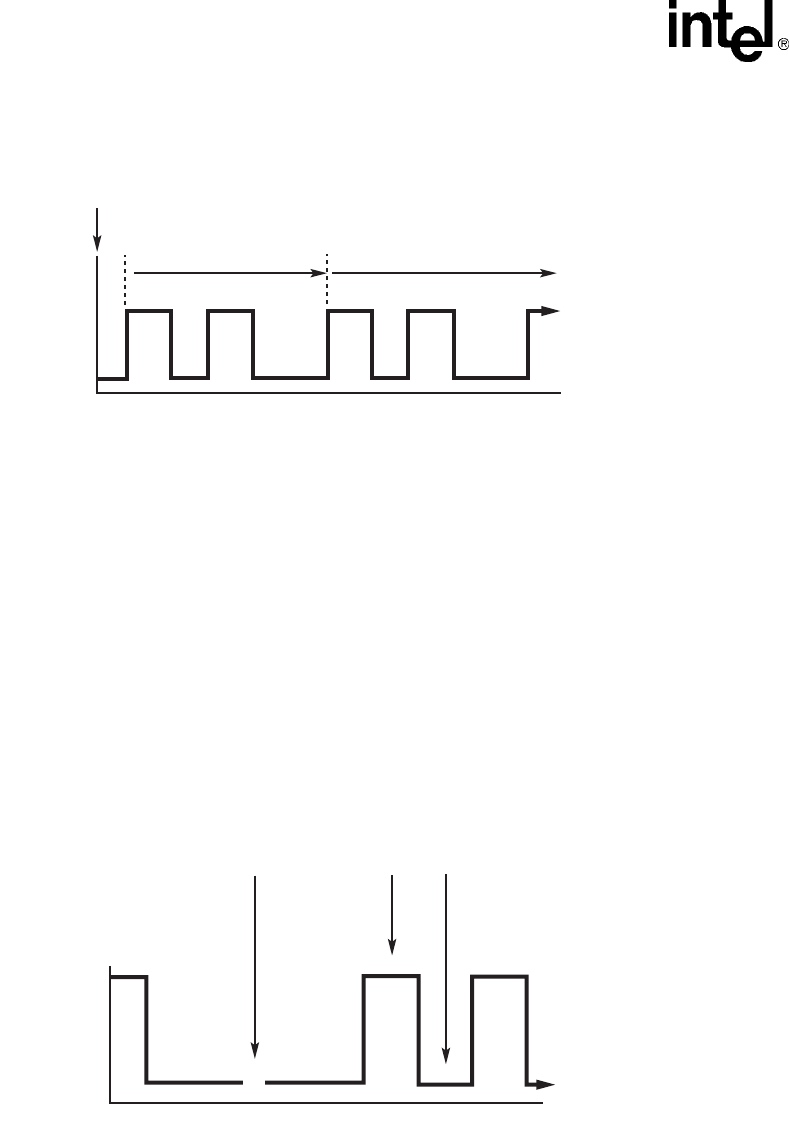
80 Voice API Programming Guide — June 2005
Call Progress Analysis
Figure 9. Cadence Detection
Once the cadence is established, the cadence values can be retrieved using the following extended
attribute functions:
ATDX_SIZEHI( )
length of the nonsilence period (in 10 msec units) for the detected cadence
ATDX_SHORTLOW( )
length of the shortest silence period for the detected cadence (in 10 msec units)
ATDX_LONGLOW( )
length of the longest silence period for the detected cadence (in 10 msec units).
Only one nonsilence period is used to define the cadence because the nonsilence periods have the
same duration.
Figure 10 shows the elements of an established cadence.
Figure 10. Elements of Established Cadence
The durations of subsequent states are compared with these fields to see if the cadence has been
broken.
nonsilence
silence
Dialing
Complete
Period Used to
Establish Cadence
Periods Compared to the
Established Cadence
The timings are given in units of 10ms.
nonsilence
silence
ATDX_LONGLOW
≈
50 50
25
ATDX_SHORTLOWATDX_SIZEHIGH
225

Voice API Programming Guide — June 2005 81
Call Progress Analysis
7.16.4 Outcomes of Cadence Detection
Cadence detection can identify the following conditions during the period used to establish the
cadence or after the cadence has been established:
•No Ringback
•Connect
•Busy
•No Answer
Although loop current detection and positive voice detection provide complementary means of
detecting a connect, cadence detection provides the only way in basic call progress analysis to
detect a no ringback, busy, or no answer.
Cadence detection can identify the following conditions during the period used to establish the
cadence:
No Ringback
While the cadence is being established, cadence detection determines whether the signal is
continuous silence or nonsilence. In this case, cadence detection returns a no ringback,
indicating there is a problem in completing the call.
Connect
While the cadence is being established, cadence detection determines whether the audio signal
departs from acceptable network standards for busy or ring signals. In this case, cadence
detection returns a connect, indicating that there was a “break” from general cadence
standards.
Cadence detection can identify the following conditions after the cadence has been established:
Connect
After the cadence has been established, cadence detection determines whether the audio signal
departs from the established cadence. In this case, cadence detection returns a connect,
indicating that there was a break in the established cadence.
No Answer
After the cadence has been established, cadence detection determines whether the cadence
belongs to a single or double ring. In this case, cadence detection can return a no answer,
indicating there was no break in the ring cadence for a specified number of times.
Busy
After the cadence has been established, cadence detection determines whether the cadence
belongs to a slow busy signal. In this case, cadence detection can return a busy, indicating that
the busy cadence was repeated for a specified number of times.
To determine whether the ring cadence is a double or single ring, compare the value returned by the
ATDX_SHORTLOW( ) function to the DX_CAP field ca_lo2rmin. If the
ATDX_SHORTLOW( ) value is less than ca_lo2rmin, the cadence is a double ring; otherwise, it
is a single ring.

82 Voice API Programming Guide — June 2005
Call Progress Analysis
7.16.5 Setting Selected Cadence Detection Parameters
Only the most commonly adjusted cadence detection parameters are discussed here. For a complete
listing and description of the DX_CAP data structure, see the Voice API Library Reference.
You should only need to adjust cadence detection parameters for network environments that do not
conform to the U.S. standard network environment (such as behind a PBX).
7.16.5.1 General Cadence Detection Parameters
The following are general cadence detection parameters in DX_CAP:
ca_stdely
Start Delay: the delay after dialing has been completed and before starting cadence detection.
This parameter also determines the start of frequency detection and positive voice detection.
Default: 25 (10 msec units) = 0.25 seconds.
Be careful with this variable. Setting this variable too small may allow switching transients or,
if too long, miss critical signaling.
ca_higltch
High Glitch: the maximum nonsilence period to ignore. Used to help eliminate spurious
nonsilence intervals. Default: 19 (in 10 msec units).
To eliminate audio signal glitches over the telephone line, the parameters ca_logltch and
ca_higltch are used to determine the minimum acceptable length of a valid silence or
nonsilence duration. Any silence interval shorter than ca_logltch is ignored, and any
nonsilence interval shorter than ca_higltch is ignored.
ca_logltch
Low Glitch: the maximum silence period to ignore. Used to help eliminate spurious silence
intervals. Default: 15 (in 10 msec units).
7.16.5.2 Cadence Detection Parameters Affecting a No Ringback
After cadence detection begins, it waits for an audio signal of nonsilence. The maximum waiting
time is determined by the parameter ca_cnosig (continuous no signal). If the length of this period of
silence exceeds the value of ca_cnosig, a no ringback is returned. Figure 11 illustrates this. This
usually indicates a dead or disconnected telephone line or some other system malfunction.
ca_cnosig
Continuous No Signal: the maximum time of silence (no signal) allowed immediately after
cadence detection begins. If exceeded, a no ringback is returned. Default: 4000 (in 10 msec
units), or 40 seconds.

Voice API Programming Guide — June 2005 83
Call Progress Analysis
Figure 11. No Ringback Due to Continuous No Signal
If the length of any period of nonsilence exceeds the value of ca_cnosil (continuous nonsilence), a
no ringback is returned, shown in Figure 12.
ca_cnosil
Continuous Nonsilence: the maximum length of nonsilence allowed. If exceeded, a no
ringback is returned. Default: 650 (in 10 msec units), or 6.5 seconds.
Figure 12. No Ringback Due to Continuous Nonsilence
7.16.5.3 Cadence Detection Parameters Affecting a No Answer or Busy
By using the ca_nbrdna parameter, you can set the maximum number of ring cadence repetitions
that will be detected before returning a no answer.
By using the ca_nbrdna and ca_nsbusy parameters, you can set the maximum number of busy
cadence repetitions.
ca_nbrdna
Number of Rings Before Detecting No Answer: the number of single or double rings to wait
before returning a no answer. Default: 4.
CA_STDELY
250
CA_CNOSIG
4000
No Ringback
Returned
The timings are given in units of 10ms.
nonsilence
silence
Dialing
Complete
≈
The timings are given in units of 10ms.
nonsilence
silence
CA_CNOSIL
650
No Ringback
Returned

84 Voice API Programming Guide — June 2005
Call Progress Analysis
ca_nsbusy
Nonsilence Busy: the number of nonsilence periods in addition to ca_nbrdna to wait before
returning a busy. Default: 0. ca_nsbusy is added to ca_nbrdna to give the actual number of
busy cadences at which to return busy. Note that even though ca_nsbusy is declared as an
unsigned variable, it can be a small negative number.
Do not allow ca_nbrdna + ca_nsbusy to equal 2. This is a foible of the 2’s complement bit
mapping of a small negative number to an unsigned variable.
7.16.5.4 Cadence Detection Parameters Affecting a Connect
You can cause cadence detection to measure the length of the salutation when the phone is
answered. The salutation is the greeting when a person answers the phone, or an announcement
when an answering machine or computer answers the phone.
By examining the length of the greeting or salutation you receive when the phone is answered, you
may be able to distinguish between an answer at home, at a business, or by an answering machine.
The length of the salutation is returned by the ATDX_ANSRSIZ( ) function. By examining the
value returned, you can estimate the kind of answer that was received.
Normally, a person at home will answer the phone with a brief salutation that lasts about 1 second,
such as “Hello” or “Smith Residence.” A business will usually answer the phone with a longer
greeting that lasts from 1.5 to 3 seconds, such as “Good afternoon, Intel Corporation.” An
answering machine or computer will usually play an extended message that lasts more than 3 or 4
seconds.
This method is not 100% accurate, for the following reasons:
•The length of the salutation can vary greatly.
•A pause in the middle of the salutation can cause a premature connect event.
•If the phone is picked up in the middle of a ringback, the ringback tone may be considered part
of the salutation, making the ATDX_ANSRSIZ( ) return value inaccurate.
In the last case, if someone answers the phone in the middle of a ring and quickly says “Hello”, the
nonsilence of the ring will be indistinguishable from the nonsilence of voice that immediately
follows, and the resulting ATDX_ANSRSIZ( ) return value may include both the partial ring and
the voice. In this case, the return value may deviate from the actual salutation by 0 to +1.8 seconds.
The salutation would appear to be the same as when someone answers the phone after a full ring
and says two words.
Note: A return value of 180 to 480 may deviate from the actual length of the salutation by 0 to +1.8
seconds.

Voice API Programming Guide — June 2005 85
Call Progress Analysis
Cadence detection will measure the length of the salutation when the ca_hedge (hello edge)
parameter is set to 2 (the default).
ca_hedge
Hello Edge: the point at which a connect will be returned to the application, either the rising
edge (immediately when a connect is detected) or the falling edge (after the end of the
salutation).
1 = rising edge. 2 = falling edge. Default: 2 (connect returned on falling edge of salutation).
Try changing this if the called party has to say “Hello” twice to trigger the answer event.
Because a greeting might consist of several words, call progress analysis waits for a specified
period of silence before assuming the salutation is finished. The ca_ansrdgl (answer deglitcher)
parameter determines when the end of the salutation occurs. This parameter specifies the maximum
amount of silence allowed in a salutation before it is determined to be the end of the salutation. To
use ca_ansrdgl, set it to approximately 50 (in 10 msec units).
ca_ansrdgl
Answer Deglitcher: the maximum silence period (in 10 msec units) allowed between words in
a salutation. This parameter should be enabled only when you are interested in measuring the
length of the salutation. Default: -1 (disabled).
The ca_maxansr (maximum answer) parameter determines the maximum allowable answer size
before returning a connect.
ca_maxansr
Maximum Answer: the maximum allowable length of ansrsize. When ansrsize exceeds
ca_maxansr, a connect is returned to the application. Default: 1000 (in 10 msec units), or 10
seconds.
Figure 13 shows how the ca_ansrdgl parameter works.
Figure 13. Cadence Detection Salutation Processing
When ca_hedge = 2, cadence detection waits for the end of the salutation before returning a
connect. The end of the salutation occurs when the salutation contains a period of silence that
exceeds ca_ansrdgl or the total length of the salutation exceeds ca_maxansr. When the connect
event is returned, the length of the salutation can be retrieved using the ATDX_ANSRSIZ( )
function.
CA_ANSRDGL
Connect Event
Returned Here
nonsilence
silence
Connection
Detected Salutation
"Good Afternoon,""Intel Corporation"
CA_ANSRDGL

86 Voice API Programming Guide — June 2005
Call Progress Analysis
After call progress analysis is complete, call ATDX_ANSRSIZ( ). If the return value is less than
180 (1.8 seconds), you have probably contacted a residence. A return value of 180 to 300 is
probably a business. If the return value is larger than 480, you have probably contacted an
answering machine. A return value of 0 means that a connect was returned because excessive
silence was detected. This can vary greatly in practice.
Note: When a connect is detected through positive voice detection or loop current detection, the
DX_CAP parameters ca_hedge, ca_ansrdgl, and ca_maxansr are ignored.
7.16.6 Obtaining Cadence Information
The functions described in this section are not supported on DM3 boards.
To return cadence information, you can use the following extended attribute functions:
ATDX_SIZEHI( )
duration of the cadence non-silence period (in 10 msec units)
ATDX_SHORTLOW( )
duration of the cadence shorter silence period (in 10 msec units)
ATDX_LONGLOW( )
duration of the cadence longer silence period (in 10 msec units)
ATDX_ANSRSIZ( )
duration of answer if a connect occurred (in 10 msec units)
ATDX_CONNTYPE( )
connection type. If ATDX_CONNTYPE( ) returns CON_CAD, the connect was due to
cadence detection.

Voice API Programming Guide — June 2005 87
8
8.Recording and Playback
This chapter discusses playback and recording features supported by the voice library. The
following topics are discussed:
•Overview of Recording and Playback . . . . . . . . . . . . . . . . . . . . . . . . . . . . . . . . . . . . . . 87
•Digital Recording and Playback . . . . . . . . . . . . . . . . . . . . . . . . . . . . . . . . . . . . . . . . . . 88
•Play and Record Functions . . . . . . . . . . . . . . . . . . . . . . . . . . . . . . . . . . . . . . . . . . . . . . 88
•Play and Record Convenience Functions . . . . . . . . . . . . . . . . . . . . . . . . . . . . . . . . . . . 88
•Voice Encoding Methods. . . . . . . . . . . . . . . . . . . . . . . . . . . . . . . . . . . . . . . . . . . . . . . . 89
•G.726 Voice Coder. . . . . . . . . . . . . . . . . . . . . . . . . . . . . . . . . . . . . . . . . . . . . . . . . . . . . 91
•Transaction Record . . . . . . . . . . . . . . . . . . . . . . . . . . . . . . . . . . . . . . . . . . . . . . . . . . . . 92
•Silence Compressed Record . . . . . . . . . . . . . . . . . . . . . . . . . . . . . . . . . . . . . . . . . . . . . 93
•Recording with the Voice Activity Detector . . . . . . . . . . . . . . . . . . . . . . . . . . . . . . . . . 95
•Streaming to Board . . . . . . . . . . . . . . . . . . . . . . . . . . . . . . . . . . . . . . . . . . . . . . . . . . . . 97
•Pause and Resume Play . . . . . . . . . . . . . . . . . . . . . . . . . . . . . . . . . . . . . . . . . . . . . . . . . 99
•Echo Cancellation Resource . . . . . . . . . . . . . . . . . . . . . . . . . . . . . . . . . . . . . . . . . . . . . 101
8.1 Overview of Recording and Playback
The primary voice processing operations provided by a voice board include:
•recording: digitizing and storing human voice
•playback: retrieving, converting, and playing the stored, digital information to reconstruct the
human voice.
The following features related to voice recording and playback operation are documented in other
chapters in this document:
•Controlling when a playback or recording terminates using I/O termination conditions is
documented in Section 6.1.2, “Setting Termination Conditions for I/O Functions”, on page 32.
•Controlling the speed and volume when messages are played back is documented in Chapter 9,
“Speed and Volume Control”.
•A method for increasing access speed for retrieving and storing voice prompts is documented
in Chapter 12, “Cached Prompt Management”.

88 Voice API Programming Guide — June 2005
Recording and Playback
8.2 Digital Recording and Playback
In digital speech recording, the voice board converts the human voice from a continuous sound
wave, or analog signal, into a digital representation. The voice board does this by frequently
sampling the amplitude of the sound wave at individual points in the speech signal.
The accuracy, and thus the quality, of the digital recording is affected by:
•the sampling rate (number of samples per second), also called digitization rate
•the precision, or resolution, of each sample (the amount of data that is used to represent 1
sample).
If the samples are taken at a greater frequency, the digital representation will be more accurate and
the voice quality will be greater. Likewise, if more bits are used to represent the sample (higher
resolution), the sample will be more accurate and the voice quality will be greater.
In digital speech playback, the voice board reconstructs the speech signal by converting the
digitized voice back into analog voltages. If the voice data is played back at the same rate at which
it was recorded, an approximation of the original speech will result.
8.3 Play and Record Functions
The C language function library includes several functions for recording and playing audio data,
such as dx_rec( ), dx_reciottdata( ), dx_play( ), and dx_playiottdata( ). Recording takes audio
data from a specified channel and encodes it for storage in memory, in a file on disk, or on a custom
device. Playing decodes the stored audio data and plays it on the specified channel. The storage
location is one factor in determining which record and play functions should be used. The storage
location affects the access speed for retrieving and storing audio data.
One or more of the following data structures are used in conjunction with certain play and record
functions: DV_TPT to specify a termination condition for the function, DX_IOTT to identify a
source or destination for the data, and DX_XPB to specify the file format, data format, sampling
rate, and resolution.
For detailed information about play and record functions, which are also known as I/O functions,
see the Voice API Library Reference.
8.4 Play and Record Convenience Functions
Several convenience functions are provided to make it easier to implement play and record
functionality in an application. Some examples are: dx_playf( ), dx_playvox( ), dx_playwav( ),
dx_recf( ), and dx_recvox( ). These functions are specific cases of the dx_play( ) and dx_rec( )
functions and run in synchronous mode.
For example, dx_playf( ) performs a playback from a single file by specifying the filename. The
same operation can be done using dx_play( ) and specifying a DX_IOTT structure with only one

Voice API Programming Guide — June 2005 89
Recording and Playback
entry for that file. Using dx_playf( ) is more convenient for a single file playback because you do
not have to set up a DX_IOTT structure for the one file and the application does not need to open
the file. dx_recf( ) provides the same single file convenience for the dx_rec( ) function.
For a complete list of I/O convenience functions and function reference information, see the Voice
API Library Reference.
8.5 Voice Encoding Methods
A digitized audio recording is characterized by several parameters as follows:
•the number of samples per second, or sampling rate
•the number of bits used to store a sample, or resolution
•the rate at which data is recorded or played
There are many encoding and storage schemes available for digitized voice. The voice encoding
methods or data formats supported on DM3 boards are listed in Table 9.

90 Voice API Programming Guide — June 2005
Recording and Playback
Note: On DM3 boards, not all voice coders are available on all boards. The availability of a voice coder
depends on the media load chosen for your board. For a comprehensive list of voice coders
supported by each board, see the Release Guide for your system release. For details on media
loads, see the Configuration Guide for your product family.
The voice encoding methods supported on Springware boards are listed in Table 10.
Table 9. Voice Encoding Methods (DM3)
Digitizing Method Sampling Rate
(kHz) Resolution (Bits) Bit Rate (Kbps) File Format
OKI ADPCM 6 4 24 VOX, WAVE
OKI ADPCM 8 4 32 VOX, WAVE
IMA ADPCM 8 4 32 VOX, WAVE
G.711 PCM
A-law and mu-law
6 8 48 VOX, WAVE
G.711 PCM
A-law and mu-law
8 8 64 VOX, WAVE
G.721 8 4 32 VOX, WAVE
Linear PCM 8 8 64 VOX, WAVE
Linear PCM 8 16 128 VOX, WAVE
Linear PCM 11 8 88 VOX, WAVE
Linear PCM 11 16 176 VOX, WAVE
TrueSpeech 8 16 8.5 VOX, WAVE
GSM 6.10 full rate
(Microsoft format)
8 (value ignored) 13 VOX, WAVE
GSM 6.10 full rate
(TIPHON format)
8 (value ignored) 13 VOX
G.726 bit exact 8 2 16 VOX, WAVE
G.726 bit exact 8 3 24 VOX, WAVE
G.726 bit exact 8 4 32 VOX, WAVE
G.726 bit exact 8 5 40 VOX, WAVE

Voice API Programming Guide — June 2005 91
Recording and Playback
Note: On Springware boards, voice coders listed here are not available in all situations on all boards, such
as for silence compressed record or speed and volume control. Whenever a restriction exists, it will
be noted. For a comprehensive list of voice coders supported by each board, see the Release Guide
for your system release.
8.6 G.726 Voice Coder
G.726 is an ITU-T recommendation that specifies an adaptive differential pulse code modulation
(ADPCM) technique for recording and playing back audio files. It is useful for applications that
require speech compression, encoding for noise immunity, and uniformity in transmitting voice and
data signals.
The voice library provides support for a G.726 bit exact voice coder that is compliant with the
ITU-T G.726 recommendation.
Audio encoded in the G.726 bit exact format complies with Voice Profile for Internet Messaging
(VPIM), a communications protocol that makes it possible to send and receive messages from
disparate messaging systems over the Internet. G.726 bit exact is the audio encoding and decoding
standard supported by VPIM.
VPIM follows the little endian ordering. The 4-bit code words of the G.726 encoding must be
packed into octets/bytes as follows:
•The first code word (A) is placed in the four least significant bits of the first octet, with the
least significant bit (LSB) of the code word (A0) in the least significant bit of the octet.
•The second code word (B) is placed in the four most significant bits of the first octet, with the
most significant bit (MSB) of the code word (B3) in the most significant bit of the octet.
Table 10. Voice Encoding Methods (Springware)
Digitizing Method Sampling Rate
(kHz) Resolution (Bits) Bit Rate (Kbps) File Format
OKI ADPCM 6 4 24 VOX, WAVE
OKI ADPCM 8 4 32 VOX, WAVE
G.711 PCM
A-law and mu-law
6 8 48 VOX, WAVE
G.711 PCM
A-law and mu-law
8 8 64 VOX, WAVE
Linear PCM 8 8 64 VOX, WAVE
Linear PCM 11 8 88 VOX, WAVE
Linear PCM 11 16 176 VOX, WAVE
GSM 6.10 full rate
(Microsoft format)
8 (value ignored) 13 WAVE
GSM 6.10 full rate
(TIPHON format)
8 (value ignored) 13 WAVE
G.726 bit exact 8 4 32 VOX

92 Voice API Programming Guide — June 2005
Recording and Playback
•Subsequent pairs of the code words are packed in the same way into successive octets, with the
first code word of each pair placed in the least significant four bits of the octet. It is preferable
to extend the voice sample with silence such that the encoded value consists of an even number
of code words. However, if the voice sample consists of an odd number of code words, then the
last code word will be discarded.
The G.726 encoding for VPIM is illustrated here:
+--+--+--+--+--+--+--+--+
|B3|B2|B1|B0|A3|A2|A1|A0|
+--+--+--+--+--+--+--+--+
MSB -> | 7| 6| 5| 4| 3| 2| 1| 0| <- LSB
+--+--+--+--+--+--+--+--+
32K ADPCM / Octet Mapping
For more information on G.726 and VPIM, see RFC 3802 on the Internet Engineering Task Force
website at http://www.ietf.org.
To use the G.726 voice coder, specify the coder in the DX_XPB structure. Then use
dx_playiottdata( ) and dx_reciottdata( ) functions to play and record with this coder.
Alternatively, you can also use dx_playvox( ) and dx_recvox( ) convenience functions.
To determine the voice resource handles used with the play and record functions, use SRL device
mapper functions to return information about the structure of the system, such as a list of all
physical boards in a system, a list of all virtual boards on a physical board, and a list of all
subdevices on a virtual board.
See the Voice API Library Reference for more information on voice functions and data structures.
See the Standard Runtime Library API Library Reference for more information on SRL functions.
8.7 Transaction Record
Transaction record enables the recording of a two-party conversation by allowing two time-division
multiplexing (TDM) bus time slots from a single channel to be recorded. This feature is useful for
call center applications where it is necessary to archive a verbal transaction or record a live
conversation. A live conversation requires two time slots on the TDM bus, but Intel voice boards
today can only record one time slot at a time. No loss of channel density is realized with this
feature. Voice activity on two channels can be summed and stored in a single file, or in a
combination of files, devices, and/or memory.
Note: Transaction record is not supported on all boards. For a list of board support, see the Release Guide
for your system release.
On DM3 boards as well as Springware boards on Windows, use the following function for
transaction record:
dx_mreciottdata( )
records voice data from two channels to a data file, memory, or custom device

Voice API Programming Guide — June 2005 93
Recording and Playback
On Springware boards on Linux, use the following functions for transaction record:
dx_recm( )
records voice data from two channels to a data file, memory, or custom device
dx_recmf( )
records voice data from two channels to a single file
See the Voice API Library Reference for a full description of functions.
8.8 Silence Compressed Record
The silence compressed record (SCR) feature is discussed in more detail in the following topics:
•Overview
•Enabling
•Encoding Methods Supported
8.8.1 Overview
The silence compressed record feature (SCR) enables recording with silent pauses eliminated. This
results in smaller recorded files with no loss of intelligibility.
On Springware boards, when the audio level is at or falls below the silence threshold for a
minimum duration of time, SCR begins. When a short burst of noise (glitch) is detected, the
compression does not end unless the glitch is longer than a specified period of time.
On DM3 boards, the SCR algorithm is based on energy detection and zero crossing. This SCR uses
different parameters than the standard SCR. Specifically, the Pre-Compensation and De-Glitch
parameters are no longer needed, and there are additional new parameters.
The SCR algorithm operates on one msec blocks of speech and uses a two-fold approach to
determine whether a sample is speech or silence. Two probability of speech values are calculated
using a zero crossing algorithm and an energy detection algorithm. These values are put together to
calculate a combined probability of speech.
The energy detection algorithm allows you to modify the background noise threshold range.
Signals above the high threshold are declared speech, and signals below the low threshold are
declared silence.
Speech or silence is declared based on the previous sample, the current combined probability of
speech in relation to the speech probability threshold and silence probability threshold parameters
and the trailing silence parameter.
8.8.2 Enabling
On DM3 boards, use dx_setparm( ) and the DXCH_SCRFEATURE define to turn silence
compressed record (SCR) on and off. Once enabled, voice record functions automatically record
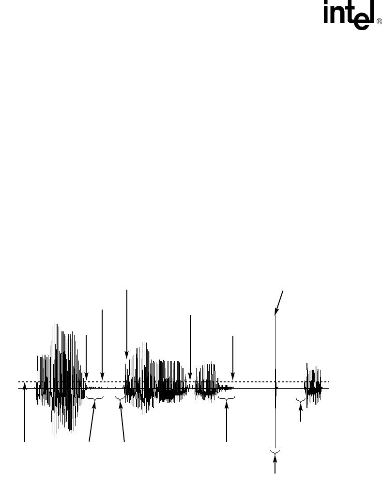
94 Voice API Programming Guide — June 2005
Recording and Playback
with SCR. For more information on modifying SCR parameters, see the Configuration Guide for
your product or product family.
On Springware boards, you enable SCR in the voice.prm file which is downloaded to the board
during initialization. You must edit this file and set appropriate values for the SCR parameters for
use in your working environment before initializing the board. You cannot enable this feature
through the voice API. After SCR is enabled in the voice.prm file, it is automatically activated by
the use of voice record functions such as dx_rec( ).
On Springware boards, the SCR parameters specify the silence threshold, the duration of silence at
the end of speech before silence compression begins, the duration of a glitch in the line which does
not stop silence compression, and more. Figure 14 illustrates how these parameters work. See the
appropriate Configuration Guide for details of the parameters and information on how to enable
and configure this feature.
Figure 14. Silence Compressed Record Parameters Illustrated
8.8.3 Encoding Methods Supported
On DM3 boards, the following encoding algorithms and sampling rates are supported in silence
compressed record (SCR):
•OKI ADPCM, 6 kHz with 4-bit samples (24 kbps) and 8 kHz with 4-bit samples (32 kbps),
VOX and WAVE file formats
•linear PCM, 8 kHz sampling 64 Kbps (8 bits), 8 kHz sampling 128 Kbps (16 bits), VOX and
WAVE file formats
SCR_THRES
(dB)
Begin
Compression
Begin
Compression
Speech
Detected
Compression
Ends Silence Less
Than SCR_T
Compression
Not Enabled
Noise Spike
(Glitch)
Compression
Continues
SCR_T
(10 ms Unit)
SCR_PC
(Bytes)
SCR_T
(10 ms Unit)
SCR_DG
(10 ms Unit)
End of
Speech
SCR_PC
(bytes)

Voice API Programming Guide — June 2005 95
Recording and Playback
•G.711 PCM, 6 kHz with 8-bit samples (48 kbps) and 8 kHz with 8-bit samples (64 kbps) using
A-law or mu-law coding, VOX and WAVE file formats
•G.721 at 8 kHz with 4-bit samples (32 kbps), VOX and WAVE file formats
•G.726 bit-exact voice coder at 8 kHz with 2-, 3-, 4-, or 5-bit samples (16, 24, 32, 40 kbps),
VOX and WAVE file formats
On Springware boards, the following encoding algorithms and sampling rates are supported in
SCR:
•6 kHz and 8 kHz OKI ADPCM
•8 kHz and 11 kHz linear PCM
•8 kHz and 11 kHz A-law PCM
•8 kHz and 11 kHz mu-law PCM
8.9 Recording with the Voice Activity Detector
Recording with the voice activity detector is discussed in the following topics:
•Overview
•Enabling
•Encoding Methods Supported
8.9.1 Overview
The dx_reciottdata( ) function, used to record voice data, has two modes that work with the voice
activity detector. One mode enables voice activity detection with event notification upon detection.
The second mode adds initial silence compression on the line before voice energy is detected; if
initial silence is greater than the default allowable amount of silence, the amount in excess is
eliminated. This mode uses the same algorithm as the silence compressed record (SCR) feature
described in Section 8.8, “Silence Compressed Record”, on page 93.
The voice activity detector (VAD) is a component in the voice software that examines the incoming
signal and determines if the signal contains significant energy and is likely to be voice.
The recording modes for voice activity detection are supported on select DM3 boards only and
with certain encoding methods only. For more information about boards supported and the features
supported on each board, see the Release Guide for your system release. For more information
about encoding methods supported, see Section 8.8.3, “Encoding Methods Supported”, on page 94.

96 Voice API Programming Guide — June 2005
Recording and Playback
8.9.2 Enabling
The modes related to the voice activity detector are specified in the mode parameter of the
dx_reciottdata( ) function. They are:
RM_VADNOTIFY
generates an event, TDX_VAD, on detection of voice energy during the recording operation
Note: TDX_VAD does not indicate function termination; it is an unsolicited event. Do not
confuse this event with the TEC_VAD event which is used in the continuous speech
processing (CSP) library.
RM_ISCR
adds initial silence compression to the VAD capability. Initial silence here refers to the amount
of silence on the line before voice activity is detected. When using RM_ISCR, the default
value for the amount of initial silence allowable is 3 seconds. Any initial silence longer than
that will be eliminated to the default allowable amount. This default value can be changed by
modifying a parameter in the .config file for the board and then generating a new .fcd file. The
0x416 parameter must be added in the [encoder] section of the .config file. For details on using
this parameter, see the DM3 Configuration Guide.
Note: The RM_ISCR mode can only be used in conjunction with RM_VADNOTIFY.
When these two modes are used together, no data is recorded as output until voice activity is
detected on the line. The TDX_VAD event indicates the initiation of voice. The output file will be
empty before voice activity is detected, although some initial silence may be included as specified
in the .fcd file.
To enable these modes, OR them to the mode parameter. For example:
t_Return=dx_reciottdata(DevHandle, Iott, Tpt, &t_Xpb, EV_ASYNC|RM_VADNOTIFY);
t_Return=dx_reciottdata(DevHandle, Iott, Tpt, &t_Xpb, EV_ASYNC|RM_VADNOTIFY|RM_ISCR);
Note: The dx_reciottdata( ) function does not perform echo-cancelled streaming. For automatic speech
recognition applications, use record or streaming functions in the continuous speech processing
(CSP) API library. For more information, see the Continuous Speech Processing API Programming
Guide and Continuous Speech Processing API Programming Guide.
8.9.3 Encoding Methods Supported
The following encoding algorithms and sampling rates are supported for recording with the voice
activity detector:
•OKI ADPCM, 6 kHz with 4-bit samples (24 kbps) and 8 kHz with 4-bit samples (32 kbps),
VOX and WAVE file formats
•linear PCM, 8 kHz sampling 64 Kbps (8 bits), 8 kHz sampling 128 Kbps (16 bits), VOX and
WAVE file formats
•G.711 PCM, 6 kHz with 8-bit samples (48 kbps) and 8 kHz with 8-bit samples (64 kbps) using
A-law or mu-law coding, VOX and WAVE file formats
•G.721 at 8 kHz with 4-bit samples (32 kbps), VOX and WAVE file formats

Voice API Programming Guide — June 2005 97
Recording and Playback
•G.726 bit-exact voice coder at 8 kHz with 2-, 3-, 4-, or 5-bit samples (16, 24, 32, 40 kbps),
VOX and WAVE file formats
8.10 Streaming to Board
The streaming to board feature is discussed in the following topics:
•Streaming to Board Overview
•Streaming to Board Functions
•Implementing Streaming to Board
•Streaming to Board Hints and Tips
8.10.1 Streaming to Board Overview
The streaming to board feature provides a way to stream data in real time to a network interface.
Unlike the standard voice play feature (store and forward method), data can be streamed with little
delay as the amount of initial data required to start the stream is configurable. The streaming to
board feature is essential for applications such as text-to-speech, distributed prompt servers, and IP
gateways.
The streaming to board feature uses a circular stream buffer to hold data, provides configurable
high and low water mark parameters, and generates events when those water marks are reached.
The streaming to board feature is not supported on Springware boards.
8.10.2 Streaming to Board Functions
The following functions are used by the streaming to board feature:
dx_OpenStreamBuffer( )
creates and initializes a circular stream buffer
dx_SetWaterMark( )
sets high and low water marks for the circular stream buffer
dx_PutStreamData( )
places data into the circular stream buffer
dx_GetStreamInfo( )
retrieves information about the circular stream buffer
dx_ResetStreamBuffer( )
resets internal data for a circular stream buffer
dx_CloseStreamBuffer( )
deletes a circular stream buffer
For details on these functions, see the Voice API Library Reference.

98 Voice API Programming Guide — June 2005
Recording and Playback
8.10.3 Implementing Streaming to Board
Perform the following steps to implement streaming to board in your application:
Note: These steps do not represent every task that must be performed to create a working application but
are intended as general guidelines for implementing streaming to board.
1. Decide on the size of the circular stream buffer. This value is used as input to the
dx_OpenStreamBuffer( ) function. To determine the circular stream buffer size, see
Section 8.10.4, “Streaming to Board Hints and Tips”, on page 98.
2. Based on the circular stream buffer and the bulk queue buffer size, decide on values for the
high and low water marks for the circular stream buffer. To determine high and low water mark
values, see Section 8.10.4, “Streaming to Board Hints and Tips”, on page 98.
3. Initialize and create a circular stream buffer using dx_OpenStreamBuffer( ).
4. Set the high and low water marks using dx_SetWaterMark( ).
5. Start the play using dx_playiottdata( ) or dx_play( ) in asynchronous mode with the io_type
field in DX_IOTT data structure set to IO_STREAM.
6. Put data in the circular stream buffer using dx_PutStreamData( ).
7. Wait for events.
The TDX_LOWWATER event is generated every time data in the buffer falls below the low
water mark. The TDX_HIGHWATER event is generated every time data in the buffer is above
the high water mark. The application receives TDX_LOWWATER and TDX_HIGHWATER
events regardless of whether or not dx_SetWaterMark( ) is used in your application. These
events are generated when there is a play operation with this buffer and are reported on the
device that is performing the play. If there is no active play, the application will not receive any
of these events.
TDX_PLAY indicates that play has completed.
8. When all files are played, issue dx_CloseStreamBuffer( ).
8.10.4 Streaming to Board Hints and Tips
Consider the following usage guidelines when implementing streaming to board in your
application:
•You can create as many circular stream buffers as needed on a channel; however, you are
limited by the amount of memory on the system. You can use more than one circular stream
buffer per play via the DX_IOTT structure. In this case, specify that the data ends in one buffer
using the STREAM_EOD flag so that the play can process the next DX_IOTT structure in the
chain.
•In general, the larger you define the circular stream buffer size, the better. Factors to take into
consideration include the average input file size, the amount of memory on your system, the
total number of channels in your system, and so on. Having an optimal circular stream buffer
size results in the high and low water marks being reached less often. In a well-tuned system,
the high and low water marks should rarely be reached.
•When adjusting circular stream buffer sizes, be aware that you must also adjust the high and
low water marks accordingly.

Voice API Programming Guide — June 2005 99
Recording and Playback
•Recommendation for the high water mark: it should be based on the following:
(size of the circular stream buffer) minus (two times the size of the bulk queue buffer)
For example, if the circular stream buffer is 100 kbytes, and the bulk queue buffer size is
8 kbytes, set the high water mark to 84 kbytes. (The bulk queue buffer size is set through the
dx_setchxfercnt( ) function.)
•Recommendation for the low water mark:
–If the bulk queue buffer size is less than 8 kbytes, the low water mark should be four times
the size of the bulk queue buffer size.
–If the bulk queue buffer size is greater than 8 kbytes and less than 16 kbytes, the low water
mark should be three times the size of the bulk queue buffer size.
–If the bulk queue buffer size is greater than 16 kbytes, the low water mark should be two
times the size of the bulk queue buffer size.
•When a TDX_LOWWATER event is received, continue putting data in the circular stream
buffer. Remember to set STREAM_EOD flag to EOD on the last piece of data.
•When a TDX_HIGHWATER event is received, stop putting data in the circular stream buffer.
If using a text-to-speech (TTS) engine, you will have to stop the engine from sending more
data. If you cannot control the output of the TTS engine, you will need to control the input to
the engine.
•It is recommended that you enable the TDX_UNDERRUN event to notify the application of
firmware underrun conditions on the board. Specify DM_UNDERRUN in dx_setevtmsk( ).
8.11 Pause and Resume Play
The voice library provides functionality for pausing a playback and resuming a playback. This
functionality is discussed in the following topics:
•Pause and Resume Play Overview
•Pause and Resume Play Functions
•Implementing Pause and Resume Play
•Pause and Resume Play Hints and Tips
8.11.1 Pause and Resume Play Overview
The pause and resume play functionality enables you to pause a play that is currently in progress
and later resume the same play. The play is resumed at the exact point it was stopped without loss
of data.
The pause and resume play functionality works using one of the following methods:
•using a pre-defined DTMF digit, set up similarly to speed and volume control in the
DX_SVCB data structure.
•programmatically using the dx_pause( ) and dx_resume( ) functions.
All voice encoding methods available in the voice library are supported for this feature. There are
no restrictions.

100 Voice API Programming Guide — June 2005
Recording and Playback
The pause and resume play feature is not supported on Springware boards.
8.11.2 Pause and Resume Play Functions
The following functions and data structure are used in the pause and resume play feature:
dx_pause( )
pauses a play currently in progress until a subsequent dx_resume( ) is issued
dx_resume( )
resumes the play that was paused using dx_pause( )
dx_setsvcond( )
sets adjustment condition for the play (in this case, a DTMF digit to pause/resume play)
DX_SVCB
data structure used by dx_setsvcond( ) to specify adjustment conditions for the play
Use these functions and data structure in conjunction with play functions, such as
dx_playiottdata( ) play function.
8.11.3 Implementing Pause and Resume Play
Follow these steps to implement pause and resume play in your application:
Note: These steps do not represent every task that must be performed to create a working application but
are intended as general guidelines for implementing pause and resume play.
1. Decide on whether to set DTMF digits to control the pause and resume play functionality. If
yes, set up the condition in the DX_SVCB data structure and call dx_setsvcond( ).
2. Set up the DX_IOTT data structure for the play operation.
3. Set up the DV_TPT data structure to specify termination conditions for the play.
4. Perform play operation on the channel; for example, use dx_playiottdata( ).
5. If you answered no to step 1, perform pause operation on the channel using dx_pause( ).
6. If you answered no to step 1, perform resume operation on the channel using dx_resume( ).
8.11.4 Pause and Resume Play Hints and Tips
Consider the following hints and tips when implementing pause play and resume play in your
application:
•If a DTMF digit is set as a termination condition, play is terminated when this condition is met,
even if a play is currently paused. That is, the termination condition takes precedence over the
pause/resume condition.
For example, let’s say you set the digit 2 as a termination condition on a play. If you press this
digit during play or while the play is paused, the play will be terminated. The play will
terminate when the DTMF termination condition is met. If play is paused, it does not wait for
the play to resume. As another example, if you set 5 seconds as the termination condition on a
play, the play will terminate after 5 seconds. The timer runs regardless of the paused condition.

Voice API Programming Guide — June 2005 101
Recording and Playback
•It does not make sense to use the same DTMF digit as a termination condition on a play and as
the pause/resume condition.
•To end a paused play, use dx_stopch( ).
8.12 Echo Cancellation Resource
The echo cancellation resource (ECR) feature is not supported on DM3 boards.
The echo cancellation resource (ECR) feature is a functional component of a voice channel. ECR is
discussed in more detail in the following topics:
•Overview of Echo Cancellation Resource
•Echo Cancellation Resource Operation
•Modes of Operation
•Echo Cancellation Resource Application Models
8.12.1 Overview of Echo Cancellation Resource
The ECR feature lets you use echo cancellation on signals external to the voice channel. The echo
cancellation capability becomes a system-wide resource that may be applied to any time-division
multiplexing (TDM) bus PCM stream. The addition of the ECR feature allows the application to
dynamically configure a voice channel as either an echo cancellation device (ECR mode) or as a
standard voice processing channel (SVP mode). In ECR mode, the voice channel can dynamically
perform echo cancellation on any TDM bus time slot signal external to the voice channel. In ECR
mode, a portion of the standard voice functionality remains available while another portion of it
becomes unavailable.
Note: The ECR feature has been replaced with the continuous speech processing (CSP) API. CSP is the
preferred method for echo cancellation and should be used where available. For more information,
see the Continuous Speech Processing API Programming Guide and Continuous Speech
Processing API Library Reference.
Prior to the implementation of the ECR feature in the voice library, each voice channel device had a
single transmit (TX) TDM bus time slot assigned to it for data communication across the TDM bus.
To connect one device to another across the TDM bus, an application would call xx_listen( )
(where xx_ is ag_, dt_, dx_, or ms_) on one voice or network device to connect to a second device’s
transmit channel. Any signal transmitted by the second device on its transmit channel (TX channel)
would be received by the first device’s receive channel (RX channel). For a full-duplex connection,
the second device would then call xx_listen( ) to connect its receive channel to the first device’s
transmit channel.
Throughout this section, reference is made to echo cancellation-specific terminology. See the
glossary for definitions of ECR terminology.
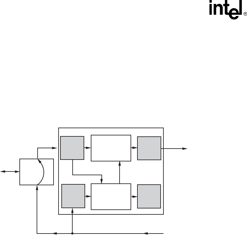
102 Voice API Programming Guide — June 2005
Recording and Playback
8.12.2 Echo Cancellation Resource Operation
The echo canceller accepts two TDM bus input data streams. One stream contains data that is
identical to that which was transmitted to the echo-producing circuit (Transmit Signal in
Figure 15). The second stream, referred to as the echo-carrying stream, contains received data
from this circuit. The received data typically contains a signal with two time-varying signals
superimposed upon one another. One signal consists of a filtered version of the transmitted data
(referred to as echo) and the other signal originates at the far end (referred to as far-end speech).
Figure 15. Echo Canceller with Relevant Input and Output Signals
The purpose of the echo canceller is to sufficiently reduce the magnitude of the echo component,
such that it does not interfere with further processing or analysis of the echo-canceled data stream.
The echo canceller performs this function by computing a model of the impulse response of the
echo path using information in the echo-carrying signal. Then, given the impulse response model
and access to the echo reference signal, the echo canceller forms an estimate of the echo. This
estimate is then subtracted from the echo-carrying signal, forming a third, echo-canceled signal.
Figure 16 illustrates the signals used in the echo canceller. For echo cancellation, an extra TDM bus
time slot is assigned to each voice device for use by the ECR feature. To activate ECR mode, the
application must route two receive time slots to the voice channel.
Echo Canceller
Echo-
Carrying
Signal
Echo-
Cancelled
Signal
Analog
Device
Echo-Estimator
and other
control circuitry
Echo-Subtractor
(Echo-Carrying) —
(Echo-Estimate) =
Echo-Cancelled
Echo-Carrying
Signal
Echo
Producing
Circuit
Echo
Echo Reference Signal
Transmit Signal
of Another Device
RX
ECR_RX
TX
(Disabled
in ECR
Mode)
ECR_TX
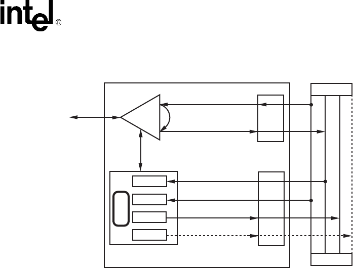
Voice API Programming Guide — June 2005 103
Recording and Playback
Figure 16. Echo Canceller Operating over a TDM bus
Once the ECR feature is enabled on a board, each voice channel is also permanently assigned two
TDM bus transmit time slots. These time slots are referred to as the voice-transmit time slot and
the echo-cancellation transmit time slot. You can retrieve the time slot numbers for each via the
dx_getxmitslot( ) and dx_getxmitslotecr( ) functions, respectively. If the ECR feature is not
enabled, the channels are not assigned the echo cancellation TDM bus transmit time slots, and ECR
mode is not possible on any voice channel of that board.
The function dx_listen( ) routes the echo-carrying signal to the voice device. A call to
dx_listenecr( ) or dx_listenecrex( ) routes the echo reference signal to the voice channel and
simultaneously activates ECR mode. The resulting echo canceller uses the echo reference signal to
estimate the echo component in the echo-carrying signal, and subtracts that estimate from the echo-
carrying signal. This process results in an echo-canceled signal with a greatly reduced echo
component.
For another device to receive the echo-canceled signal output by the echo canceller, it calls
dx_getxmitslotecr( ) to retrieve the echo canceller’s transmit time-slot number, and calls
xx_listen( ) (where xx_ is ag_, dt_, dx_, or ms_) to connect its receive channel to the echo-
canceled signal.
To return the voice channel to standard voice processing (SVP) mode, the application calls
dx_unlistenecr( ) on the voice channel to stop the echo canceller, disable ECR mode, and
disconnect the echo canceller’s receive channel.
For technical information on ECR functions, see the Voice API Library Reference.
For examples of echo cancellation configurations, see Section 8.12.4, “Echo Cancellation Resource
Application Models”, on page 105.
SCbus
Echo
Voice
Device SCbus
Echo-Generating
Signal
Echo-Carrying
Signal
Echo-Carrying Signal
Echo-Reference Signal
Enabled in ECR Mode
Disabled in ECR Mode
Telephone
Network
Switching Handler
TX
RX
Analog
Device
Signaling
VOX_TX
VOX_RX
ECR_RX
ECR_TX
E
C
R

104 Voice API Programming Guide — June 2005
Recording and Playback
8.12.3 Modes of Operation
The echo cancellation resource feature has two modes of operation as discussed in the following
topics:
•Overview of Modes
•Standard Voice Processing (SVP) Mode
•Echo Cancellation Resource (ECR) Mode
8.12.3.1 Overview of Modes
When the ECR feature is enabled at initialization time on a supported board, there are two possible
modes of operation: SVP and ECR. Until ECR mode is activated, the board operates in the
Standard Voice Processing (SVP) mode, which offers default echo cancellation. The ECR mode,
which provides high-performance echo cancellation, can be dynamically activated or deactivated
on any voice channel of the enabled board.
To enable ECR mode, set EC_Resource to ON in the .cfg file or in the configuration manager
(DCM) (Windows only) when configuring the board.
8.12.3.2 Standard Voice Processing (SVP) Mode
All voice channels are initially in the SVP mode with the default echo cancellation for ECR
feature-enabled boards. The SVP mode utilizes a 48 tap (6 ms) echo canceller. In SVP mode, all
voice functions operate as usual, with one exception. If a channel in SVP mode is playing a file and
listening (via a dx_listen( ) function), then playback transmits data on both the standard voice-
transmit time slot and the echo-cancellation transmit time slot. The standard voice-transmit time
slot carries the play signal. The echo cancellation time slot carries an echo-canceled version of the
signal from the receive time slot. This echo-canceled signal is derived from the original play signal
(the echo reference) and the signal from the receive time slot specified in the dx_listen( ) function
(the echo carrying signal).
8.12.3.3 Echo Cancellation Resource (ECR) Mode
Any voice channel can be placed into ECR mode via the dx_listenecr( ) or dx_listenecrex( )
function on an ECR feature-enabled board. When a voice channel is placed in ECR mode, the echo
reference TDM bus time slot is specified and the high performance echo canceller is activated. The
ECR mode supplies 128 tap (16 ms) echo cancellation.
When an echo carrying signal is provided as an input to the ECR by an associated dx_listen( )
function, an echo-canceled version of that signal is produced on the echo-cancellation TDM bus
time slot. If no echo carrying signal is defined, the contents of the echo-cancellation transmit time
slot are undefined and unpredictable. Other characteristics of the echo canceller can be set if the

Voice API Programming Guide — June 2005 105
Recording and Playback
ECR mode is activated using the dx_listenecrex( ) function. For technical information on ECR
functions, see the Voice API Library Reference.
Note: dx_listen( ) may precede or follow the dx_listenecr( ) or dx_listenecrex( ) function. If multiple
dx_listen( ) and dx_listenecr( ) or dx_listenecrex( ) function calls are issued against a single
channel, the echo cancellation operates on the last two issued. Successive dx_listenecr( ) or
dx_listenecrex( ) functions can be issued without requiring any dx_unlistenecr( ) between them.
While a channel is in ECR mode, a number of standard voice operations are not available. The
unavailable operations include the following:
•play
•record (8 kHz PCM record is the only supported record encoding when a channel is in the ECR
mode. Any such 8 kHz PCM record is a recording of the echo-canceled signal.)
•dial
•tone generation
•R2/MF
•transaction record
If a channel is actively performing any of the above operations, a dx_listenecr( ) or
dx_listenecrex( ) function is not performed, and the function returns an error to the application.
Conversely, if a channel is in ECR mode, a request for any of these operations is not honored,
except for the record noted. A channel may be returned to SVP mode dynamically via the
dx_unlistenecr( ) function.
8.12.4 Echo Cancellation Resource Application Models
Two application models are provided in this section to illustrate building an echo-canceled
connection via the TDM bus:
•How to Set Up the ECR Bridge
•How to Set Up an ECR Play Over the TDM bus
8.12.4.1 How to Set Up the ECR Bridge
This application model uses two Modular Station Interface (MSI/SC) station devices connected via
the TDM bus to two voice channel devices. The voice channel devices are operating in ECR mode.
Two telephones (Figure 17, “ECR Bridge Example Diagram”, on page 106) are connected to the
MSI/SC stations for providing input and for listening to the echo-canceled output of each voice
device.
Perform the following to set up an ECR bridge:
1. Get TDM bus transmit time slots of both MSI/SC devices and the ECR transmit time slots of
the two voice channel devices.
ms_getxmitslot (MS1, &MS1_TX);
ms_getxmitslot (MS2, &MS2_TX);
dx_getxmitslotecr (CH1, &CH1_ECR_TX);
dx_getxmitslotecr (CH2, &CH2_ECR_TX);
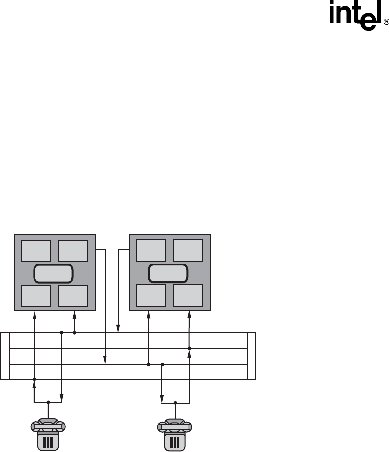
106 Voice API Programming Guide — June 2005
Recording and Playback
2. Have both MSI/SC stations listen to the ECR transmit of the opposite voice channel.
ms_listen (MS1, &CH2_ECR_TX);
ms_listen (MS2, &CH1_ECR_TX);
3. Have both voice channel devices listen to their corresponding MSI/SC station device.
dx_listen (CH1, &MS1_TX);
dx_listen (CH2, &MS2_TX);
4. Have each voice channel connect its echo canceller’s receive time slot to the opposite echo
canceller’s ECR transmit. These signals are used as echo reference signals.
dx_listenecr (CH1, & CH2_ECR_TX);
dx_listenecr (CH2, & CH1_ECR_TX);
Figure 17. ECR Bridge Example Diagram
Example
#include <stdio.h>
#include <windows.h> /* Windows applications only */
#include <srllib.h>
#include <dxxxlib.h>
#include <msilib.h>
#include <errno.h> /* Linux applications only */
main()
{
int chdev1, chdev2; /* Voice channel device handles */
int msdev1, msdev2; /* MSI/SC station device handles */
SC_TSINFO sc_tsinfo; /* TDM bus time slot information structure */
long scts; /* Pointer to TDM bus time slot */
long ms1txts, ms2txts, /* Transmit time slots of stations 1 & 2 */
ch1ecrtxts, ch2ecrtxts; /* Transmit time slots of echo-cancellers on voice channels 1 & 2 */
CH2
CH2_ECR_TX
EC
TX
RX
ECR
TX
ECR
RX
EC
ECR
TX
ECR
RX
RX
TX
CH1
CH1_ECR_TX
MS2_TX
MS1_TX
S
C
b
u
s
S
C
b
u
s

Voice API Programming Guide — June 2005 107
Recording and Playback
/* Open voice board 1 channel 1 device */
if ((chdev1 = dx_open("dxxxB1C1", 0)) == -1) {
printf("Cannot open channel dxxxB1C1. errno = %d", errno);
exit(1);
}
/* Open voice board 1 channel 2 device */
if ((chdev2 = dx_open("dxxxB1C2", 0)) == -1) {
printf("Cannot open channel dxxxB1C2. errno = %d", errno);
exit(1);
}
/* Open MSI/SC board 1 station 1 device */
if ((msdev1 = ms_open("msiB1C1", 0)) == -1) {
printf("Cannot open station msiB1C1. errno = %d", errno);
exit(1);
}
/* Open MSI/SC board 1 station 2 device */
if ((msdev2 = ms_open("msiB1C2", 0)) == -1) {
printf("Cannot open station msiB1C2. errno = %d", errno);
exit(1);
}
/* Initialize a TDM bus time slot information */
sc_tsinfo.sc_numts = 1;
sc_tsinfo.sc_tsarrayp = &scts;
/* Get TDM bus time slot connected to transmit of MSI/SC station 1 on board 1 */
if (ms_getxmitslot(msdev1, &sc_tsinfo) == -1) {
printf("Error message = %s, on %s", ATDV_ERRMSGP(msdev1), ATDV_NAMEP(msdev1));
exit(1);
}
ms1txts = scts;
/* Get TDM bus time slot connected to transmit of MSI/SC station 2 on board 1 */
if (ms_getxmitslot(msdev2, &sc_tsinfo) == -1) {
printf("Error message = %s, on %s", ATDV_ERRMSGP(msdev2), ATDV_NAMEP(msdev2));
exit(1);
}
ms2txts = scts;
/* Get TDM bus time slot connected to transmit of voice channel 1 on board 1 */
if (dx_getxmitslotecr(chdev1, &sc_tsinfo) == -1) {
printf("Error message = %s, on %s", ATDV_ERRMSGP(chdev1), ATDV_NAMEP(chdev1));
exit(1);
}
ch1ecrtxts = scts;
/* Get TDM bus time slot connected to transmit of voice channel 2 on board 1 */
if (dx_getxmitslotecr(chdev2, &sc_tsinfo) == -1) {
printf("Error message = %s, on %s", ATDV_ERRMSGP(chdev2), ATDV_NAMEP(chdev2));
exit(1);
}
ch2ecrtxts = scts;
/* Have MSI/SC station 1 listen to channel 2's echo-cancelled transmit */
if (ms_listen(msdev1, &sc_tsinfo) == -1) {
printf("Error message = %s, on %s", ATDV_ERRMSGP(msdev1), ATDV_NAMEP(msdev1));
exit(1);
}
scts = ch1ecrtxts;
/* Have MSI/SC station 2 listen to channel 1's echo-cancelled transmit */
if (ms_listen(msdev2, &sc_tsinfo) == -1) {
printf("Error message = %s, on %s", ATDV_ERRMSGP(msdev2), ATDV_NAMEP(msdev2));
exit(1);
}

108 Voice API Programming Guide — June 2005
Recording and Playback
scts = ms1txts;
/* Have channel 1 listen to station 1's transmit */
if (dx_listen(chdev1, &sc_tsinfo) == -1) {
printf("Error message = %s, on %s", ATDV_ERRMSGP(chdev1), ATDV_NAMEP(chdev1));
exit(1);
}
scts = ms2txts;
/* Have channel 2 listen to station 2's transmit */
if (dx_listen(chdev2, &sc_tsinfo) == -1) {
printf("Error message = %s, on %s", ATDV_ERRMSGP(chdev2), ATDV_NAMEP(chdev2));
exit(1);
}
scts = ch2ecrtxts;
/* Have channel 1's echo-canceller listen to channel 2's echo-cancelled transmit */
if (dx_listenecr(chdev1, &sc_tsinfo) == -1) {
printf("Error message = %s, on %s", ATDV_ERRMSGP(chdev1), ATDV_NAMEP(chdev1));
exit(1);
}
scts = ch1ecrtxts;
/* Have channel 2's echo-canceller listen to channel 1's echo-cancelled transmit */
if (dx_listenecr(chdev2, &sc_tsinfo) == -1) {
printf("Error message = %s, on %s", ATDV_ERRMSGP(chdev2), ATDV_NAMEP(chdev2));
exit(1);
}
/* Bridge connected, both stations receive echo-cancelled signal */
/*
*
* Continue
*
*/
/* Then perform xx_unlisten() and dx_unlistenecr(), plus all necessary xx_close()s */
if (ms_unlisten(msdev2) == -1) {
printf("Error message = %s, on %s", ATDV_ERRMSGP(msdev2), ATDV_NAMEP(msdev2));
exit(1);
}
if (ms_unlisten(msdev1) == -1) {
printf("Error message = %s, on %s", ATDV_ERRMSGP(msdev1), ATDV_NAMEP(msdev1));
exit(1);
}
if (dx_unlistenecr(chdev2) == -1) {
printf("Error message = %s, on %s", ATDV_ERRMSGP(chdev2), ATDV_NAMEP(chdev2));
exit(1);
}
if (dx_unlistenecr(chdev1) == -1) {
printf("Error message = %s, on %s", ATDV_ERRMSGP(chdev1), ATDV_NAMEP(chdev1));
exit(1);
}
if (dx_unlisten(chdev2) == -1) {
printf("Error message = %s, on %s", ATDV_ERRMSGP(chdev2), ATDV_NAMEP(chdev2));
exit(1);
}
if (dx_unlisten(chdev1) == -1) {
printf("Error message = %s, on %s", ATDV_ERRMSGP(chdev1), ATDV_NAMEP(chdev1));
exit(1);
}
if (dx_close(chdev1) == -1) {
printf("Error message = %s, on %s", ATDV_ERRMSGP(chdev1), ATDV_NAMEP(chdev1));

Voice API Programming Guide — June 2005 109
Recording and Playback
exit(1);
}
if (dx_close(chdev2) == -1) {
printf("Error message = %s, on %s", ATDV_ERRMSGP(chdev2), ATDV_NAMEP(chdev2));
exit(1);
}
if (ms_close(msdev1) == -1) {
printf("Error message = %s, on %s", ATDV_ERRMSGP(chdev1), ATDV_NAMEP(chdev1));
exit(1);
}
if (ms_close(msdev2) == -1) {
printf("Error message = %s, on %s", ATDV_ERRMSGP(msdev2), ATDV_NAMEP(msdev2));
exit(1);
}
return(0);
}
8.12.4.2 How to Set Up an ECR Play Over the TDM bus
In this model, two MSI/SC station devices are connected via the TDM bus to two voice channel
devices. The second voice channel device is operating in ECR mode. Two telephones are connected
to the MSI/SC stations for providing input and listening to the echo-cancelled output of the second
voice device, and to the non-echo-cancelled output of the first voice device. See Figure 18, “An
ECR Play Over the TDM bus”, on page 110.
Perform the following to set up an ECR play over the TDM bus:
1. Get TDM bus transmit time slots of both MSI/SC devices and the ECR transmit time slots of
the two voice channel devices.
ms_getxmitslot (MS1, &MS1_TX);
dx_getxmitslot (CH1, &CH1_TX);
dx_getxmitslotecr (CH2, &CH2_ECR_TX);
2. Have the MSI/SC station 1 listen to the transmit (TX) of channel 1.
ms_listen (MS1, & CH1_TX);
3. Have MSI/SC station 2 listen to the ECR transmit of channel 2.
ms_listen (MS2, & CH2_ECR_TX);
4. Have voice channel 2 listen to MSI/SC station 1’s transmit.
dx_listen (CH2, & MS1_TX);
5. Have voice channel 2 connect its echo canceller’s receive time slot to transmit of channel 1.
This signal is used as the echo reference signal.
dx_listenecr (CH2, & CH1_TX);
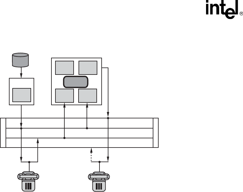
110 Voice API Programming Guide — June 2005
Recording and Playback
Figure 18. An ECR Play Over the TDM bus
Example
#include <stdio.h>
#include <windows.h> /* Windows applications only */
#include <srllib.h>
#include <dxxxlib.h>
#include <msilib.h>
#include <errno.h> /* Linux applications only */
mmain()
{
int chdev1, chdev2; /* Voice channel device handles */
int msdev1, msdev2; /* MSI/SC station device handles */
SC_TSINFO sc_tsinfo; /* TDM bus time slot information structure */
long scts; /* Pointer to TDM bus time slot */
long ms1txts, /* Transmit time slots of stations 1 & 2 */
ch1txts, ch2ecrtxts; /* Transmit time slots of echo-cancellers on
voice channels 1 & 2 */
/* Open voice board 1 channel 1 device */
if ((chdev1 = dx_open("dxxxB1C1", 0)) == -1) {
printf("Cannot open channel dxxxB1C1. errno = %d", errno);
exit(1);
}
/* Open voice board 1 channel 2 device */
if ((chdev2 = dx_open("dxxxB1C2", 0)) == -1) {
printf("Cannot open channel dxxxB1C2. errno = %d", errno);
exit(1);
}
/* Open MSI/SC board 1 station 1 device */
if ((msdev1 = ms_open("msiB1C1", 0)) == -1) {
printf("Cannot open station msiB1C1. errno = %d", errno);
exit(1);
}
TX
CH2
EC
ECR
TX
ECR
RX
RX
TX
(Unused)
CH2_ECR_TX
MS2_TX (unused)
CH1_TX
MS1_TX
S
C
b
u
s
S
C
b
u
s
Voice
File
CH1
MS1 MS2

Voice API Programming Guide — June 2005 111
Recording and Playback
/* Open MSI/SC board 1 station 2 device */
if ((msdev2 = ms_open("msiB1C2", 0)) == -1) {
printf("Cannot open station msiB1C2. errno = %d", errno);
exit(1);
}
/* Initialize an TDM bus time slot information */
sc_tsinfo.sc_numts = 1;
sc_tsinfo.sc_tsarrayp = &scts;
/* Get TDM bus time slot connected to transmit of voice channel 1 on board 1 */
if (ms_getxmitslot(msdev1, &sc_tsinfo) == -1) {
printf("Error message = %s, on %s", ATDV_ERRMSGP(msdev1), ATDV_NAMEP(msdev1));
exit(1);
}
ms1txts = scts;
/* Get TDM bus time slot connected to transmit of voice channel 1 on board 1*/
if (dx_getxmitslot(chdev1, &sc_tsinfo) == -1) {
printf("Error message = %s, on %s", ATDV_ERRMSGP(chdev1), ATDV_NAMEP(chdev1));
exit(1);
}
ch1txts = scts;
/* Get TDM bus time slot connected to transmit of voice channel 1 on board 1 */
if (dx_getxmitslotecr(chdev2, &sc_tsinfo) == -1) {
printf("Error message = %s, on %s", ATDV_ERRMSGP(chdev2), ATDV_NAMEP(chdev2));
exit(1);
}
ch2ecrtxts = scts;
/* Have station 1 listen to file played by voice channel 1 */
scts = ch1txts;
if (ms_listen(msdev1, &sc_tsinfo) == -1) {
printf("Error message = %s, on %s", ATDV_ERRMSGP(msdev1), ATDV_NAMEP(msdev1));
exit(1);
}
/* Have station 2 listen to echo-cancelled output of voice channel 2 */
scts = ch2ecrtxts;
if (ms_listen(msdev2, &sc_tsinfo) == -1) {
printf("Error message = %s, on %s", ATDV_ERRMSGP(msdev2), ATDV_NAMEP(msdev2));
exit(1);
}
/* Have voice channel 2 listen to echo-carrying signal from station 1 */
scts = ms1txts;
if (dx_listen(chdev2, &sc_tsinfo) == -1) {
printf("Error message = %s, on %s", ATDV_ERRMSGP(chdev1), ATDV_NAMEP(chdev1));
exit(1);
}
/* And activate the ECR feature on voice channel 2, with the echo-reference signal
coming from voice channel 1 */
scts = ch1txts;
if (dx_listenecr(chdev2, &sc_tsinfo) == -1) {
printf("Error message = %s, on %s", ATDV_ERRMSGP(chdev2), ATDV_NAMEP(chdev2));
exit(1);
}
/* Setup completed, any signal transmitted from channel device 1,
* will a) be received by station 1,
* b) contribute echo to the transmit of station 1,
* c) will be heard AFTER echo-cancellation (on channel 2) by
* station 2.*/

112 Voice API Programming Guide — June 2005
Recording and Playback
/*
.
. Continue
.
*/
/* Then perform xx_unlisten() and dx_unlistenecr(), plus all necessary xx_close()s */
if (ms_unlisten(msdev2) == -1) {
printf("Error message = %s, on %s", ATDV_ERRMSGP(msdev2), ATDV_NAMEP(msdev2));
exit(1);
}
if (ms_unlisten(msdev1) == -1) {
printf("Error message = %s, on %s", ATDV_ERRMSGP(msdev1), ATDV_NAMEP(msdev1));
exit(1);
}
if (dx_unlistenecr(chdev2) == -1) {
printf("Error message = %s, on %s", ATDV_ERRMSGP(chdev2), TDV_NAMEP(chdev2));
exit(1);
}
if (dx_unlisten(chdev2) == -1) {
printf("Error message = %s, on %s", ATDV_ERRMSGP(chdev2), ATDV_NAMEP(chdev2));
exit(1);
}
if (dx_close(chdev1) == -1) {
printf("Error message = %s, on %s", ATDV_ERRMSGP(chdev1), ATDV_NAMEP(chdev1));
exit(1);
}
if (dx_close(chdev2) == -1) {
printf("Error message = %s, on %s", ATDV_ERRMSGP(chdev2), ATDV_NAMEP(chdev2));
exit(1);
}
if (ms_close(msdev1) == -1) {
printf("Error message = %s, on %s", ATDV_ERRMSGP(msdev1), ATDV_NAMEP(msdev1));
exit(1);
}
if (ms_close(msdev2) == -1) {
printf("Error message = %s, on %s", ATDV_ERRMSGP(msdev2), ATDV_NAMEP(msdev2));
exit(1);
}
return(0);
}

Voice API Programming Guide — June 2005 113
9
9.Speed and Volume Control
This chapter describes how to control the speed and volume of play on a channel. The following
topics are discussed:
•Speed and Volume Control Overview . . . . . . . . . . . . . . . . . . . . . . . . . . . . . . . . . . . . . . 113
•Speed and Volume Convenience Functions. . . . . . . . . . . . . . . . . . . . . . . . . . . . . . . . . . 113
•Speed and Volume Adjustment Functions. . . . . . . . . . . . . . . . . . . . . . . . . . . . . . . . . . . 114
•Speed and Volume Modification Tables . . . . . . . . . . . . . . . . . . . . . . . . . . . . . . . . . . . . 114
•Play Adjustment Digits . . . . . . . . . . . . . . . . . . . . . . . . . . . . . . . . . . . . . . . . . . . . . . . . . 118
•Setting Play Adjustment Conditions . . . . . . . . . . . . . . . . . . . . . . . . . . . . . . . . . . . . . . . 118
•Explicitly Adjusting Speed and Volume . . . . . . . . . . . . . . . . . . . . . . . . . . . . . . . . . . . . 118
9.1 Speed and Volume Control Overview
The voice software contains functions and data structures to control the speed and volume of play
on a channel. This allows an end user to control the speed or volume of a message by entering a
DTMF tone, for example.
On DM3 boards, speed can be controlled on playbacks using the following encoding methods:
•OKI ADPCM 32 kbps
•G.711 PCM A-law or mu-law encoding 64 kbps
•linear PCM 64 kbps and 128 kbps
On Springware boards, speed can be controlled on playbacks using 24 kbps or 32 kbps ADPCM
only.
Volume can be controlled on all playbacks regardless of the encoding algorithm. For a list of
supported encoding methods, see Section 8.5, “Voice Encoding Methods”, on page 89.
9.2 Speed and Volume Convenience Functions
The convenience functions set a digit that will adjust speed or volume, but do not use any data
structures. These convenience functions will only function properly if you use the default settings
of the speed or volume modification tables. These functions assume that the modification tables
have not been modified. The convenience functions are:
dx_addspddig( )
adds a digit that will modify speed by a specified amount

114 Voice API Programming Guide — June 2005
Speed and Volume Control
dx_addvoldig( )
adds a digit that will modify volume by a specified amount
See the Voice API Library Reference for detailed information about these functions.
9.3 Speed and Volume Adjustment Functions
Speed or volume can be adjusted explicitly or can be set to adjust in response to a preset condition,
such as a specific digit. For example, speed could be set to increase a certain amount when “1” is
pressed on the telephone keypad. The functions used for speed and volume adjustment are:
dx_setsvcond( )
Sets conditions that adjust speed or volume. Use this function to adjust speed or volume in
response to a DTMF digit or start of play.
dx_adjsv( )
Adjusts speed or volume explicitly. Use this function if your adjustment condition is not a digit
or start of play. For example, the application could call this function after detecting a spoken
word (voice recognition) or a certain key on the keyboard.
See the Voice API Library Reference for detailed information about these functions.
9.4 Speed and Volume Modification Tables
Each channel has a speed or volume modification table for play speed or play volume adjustments.
Except for the value of the settings, the table is the same for speed and volume.
Each speed or volume modification table (SVMT) table has 21 entries, 20 that allow for a
maximum of 10 increases and decreases in speed or volume. The entry in the middle of the table is
referred to as the “origin” entry that represents normal speed or volume. The normal speed or
volume is how playback occurs when the speed and volume control feature is not used. See
Table 11, “Default Speed Modification Table”, on page 116 and Table 12, “Default Volume
Modification Table”, on page 117.
The origin, or normal speed or volume, is the basis for all settings in the table. Typically, the origin
is set to 0. Speed and volume increases or decreases by moving up or down the tables. Other entries
in the table specify a speed or volume setting in terms of a deviation from normal. For example, if a
speed modification table (SMT) entry is -10, this value represents a 10% decrease from the normal
speed.
Although the origin is typically set to normal speed/volume, changing the setting of the origin does
not affect the other settings, because all values in the SVMT are based on a deviation from normal
speed/volume.
Speed and volume control adjustments are specified by moving the current speed/volume pointer in
the table to another SVMT table entry; this translates to increasing or decreasing the current
speed/volume to the value specified in the table entry.

Voice API Programming Guide — June 2005 115
Speed and Volume Control
A speed/volume adjustment stays in effect until the next adjustment on that channel or until a
system reset.
The SVMT is like a 21-speed bicycle. You can select the gear ratio for each of the 21 speeds before
you go for a ride (by changing the values in the SVMT). And you can select any gear once you are
on the bike, like adjusting the current speed/volume to any setting in the SVMT.
To change the default values of the speed or volume modification table, use the dx_setsvmt( )
function, which in turn uses the DX_SVMT data structure. To return the current values of a table to
the DX_SVMT structure, use dx_getsvmt( ). The DX_SVCB data structure uses this table when
setting adjustment conditions.
See the Voice API Library Reference for detailed information about these functions and data
structures.
Adjustments to speed or volume are made by dx_adjsv( ) and dx_setsvcond( ) according to the
speed or volume modification table settings. These functions adjust speed or volume to one of the
following:
•a specified level (that is, to a specified absolute position in the speed table or volume table)
•a change in level (that is, by a specified number of steps up or down in the speed table or
volume table)
For example, by default, each entry in the volume modification table is equivalent to 2 dB from the
origin. Volume could be decreased by 2 dB by specifying position 1 in the table, or by moving one
step down from the origin.

116 Voice API Programming Guide — June 2005
Speed and Volume Control
The default speed modification table is shown in Table 11.
Consider the following usage information on the speed modification table:
•Each entry in the table is a percentage deviation from the default play speed (“origin”). For
example, the decrease[6] position reduces speed by 40%. This is four steps from the origin.
•The total speed modification range is from -50% to +50%. In this table, the lowest position
used is the decrease[5] position. The remaining decrease fields are set to -128 (80h). If these
“nonadjustment” positions are selected, the default action is to play at the decrease[5] speed.
•These fields can be reset, as long as no values lower than -50 are used. For example, you could
spread the 50% speed decrease over 10 steps rather than 5. Similarly, you could spread the
50% speed increase over 10 steps rather than 5.
•The default entries for index values -10 to -6 and +6 to +10 are -128 which represent a null-
entry. To customize the table entries, you must use the dx_setsvmt( ) function.
•On DM3 boards, when adjustment is associated with a DTMF digit, speed can be increased or
decreased in increments of 1 (10%) only. To achieve an increase in speed of 30% for example,
the user would press the DTMF digit three times.
Table 11. Default Speed Modification Table
Table Entry Default Value (%) Absolute Position
decrease[0] -128 (80h) -10
decrease[1] -128 (80h) -9
decrease[2] -128 (80h) -8
decrease[3] -128 (80h) -7
decrease[4] -128 (80h) -6
decrease[5] -50 -5
decrease[6] -40 -4
decrease[7] -30 -3
decrease[8] -20 -2
decrease[9] -10 -1
origin 0 0
increase[0] +10 1
increase[1] +20 2
increase[2] +30 3
increase[3] +40 4
increase[4] +50 5
increase[5] -128 (80h) 6
increase[6] -128 (80h) 7
increase[7] -128 (80h) 8
increase[8] -128 (80h) 9
increase[9] -128 (80h) 10

Voice API Programming Guide — June 2005 117
Speed and Volume Control
The default volume modification table is shown in Table 12.
Consider the following usage information on the volume modification table:
•Each entry in the table is a deviation in decibels from the starting point or volume (“origin”).
Each entry in the table is equivalent to 2 dB from the origin. Volume can be decreased 2 dB by
specifying position 1 in the table, or by moving one step down. For example, the increase[1]
position (two steps from the origin) increases volume by 4 dB.
•The total volume modification range is from -20 dB to +10 dB. In this table, the highest
position utilized is the increase[4] position. The remaining increase fields are set to -128 (80h).
If these “non-adjustment” positions are selected, the default action is to play at the increase[4]
volume. These fields can be reset, as long as no values higher than +10 are used; for example,
you could spread the 10 dB volume increase over 10 steps rather than 5.
•In the volume modification table, the default entries for index values +6 to +10 are -128 which
represent a null-entry. To customize the table entries, you must use the dx_setsvmt( ) function.
•On DM3 boards, when adjustment is associated with a DTMF digit, volume can be increased
or decreased in increments of 1 (2 dB) only. To achieve an increase in volume of 6 dB for
example, the user would press the DTMF digit three times.
Table 12. Default Volume Modification Table
Table Entry Default Value (dB) Absolute Position
decrease[0] -20 -10
decrease[1] -18 -9
decrease[2] -16 -8
decrease[3] -14 -7
decrease[4] -12 -6
decrease[5] -10 -5
decrease[6] -08 -4
decrease[7] -06 -3
decrease[8] -04 -2
decrease[9] -02 -1
origin 0 0
increase[0] +02 1
increase[1] +04 2
increase[2] +06 3
increase[3] +08 4
increase[4] +10 5
increase[5] -128 (80h) 6
increase[6] -128 (80h) 7
increase[7] -128 (80h) 8
increase[8] -128 (80h) 9
increase[9] -128 (80h) 10

118 Voice API Programming Guide — June 2005
Speed and Volume Control
9.5 Play Adjustment Digits
The voice software processes play adjustment digits differently from normal digits:
•If a play adjustment digit is entered during playback, it causes a play adjustment only and has
no other effect. This means that the digit is not added to the digit queue; it cannot be retrieved
with the dx_getdig( ) function.
•On DM3 boards, digits that are used for play adjustment may also be used as a terminating
condition. If a digit is defined as both, then both actions are applied upon detection of that
digit.
•On Springware boards, digits that are used for play adjustment will not be used as a
terminating condition. If a digit is defined as both, then the play adjustment will take priority.
•If the digit queue contains adjustment digits when a play begins and play adjustment is set to
be level sensitive, the digits will affect the speed or volume and then be removed from the
queue.
9.6 Setting Play Adjustment Conditions
Adjustment conditions are set in the same way for speed or volume. The following steps describe
how to set conditions upon which volume should be adjusted:
1. Set up the volume modification table (if you do not want to use the defaults):
•Set up the DX_SVMT structure to specify the size and number of the steps in the table.
•Call the dx_setsvmt( ) function, which points to the DX_SVMT structure, to modify the
volume modification table (dx_setsvmt( ) can also be used to reset the table to its default
values).
2. Set up the DX_SVCB structure to specify the condition, the size, and the type of adjustment.
3. Call dx_setsvcond( ), which points to an array of DX_SVCB structures. All subsequent plays
will adjust volume as required whenever one of the conditions specified in the array occurs.
See the Voice API Library Reference for more information about these functions and data
structures.
9.7 Explicitly Adjusting Speed and Volume
Speed and volume adjustments are made in the same way. The following steps describe how to
adjust speed, but you can use exactly the same procedure for volume:
1. Set up the speed modification table (if you do not want to use the defaults):
•Set up the DX_SVMT structure to specify the size and number of the steps in the table.
•Call the dx_setsvmt( ) function, which points to the DX_SVMT structure, to modify the
speed modification table (dx_setsvmt( ) can also be used to reset the table to its default
values).
2. When required, call dx_adjsv( ) to adjust the speed modification table by specifying the size
and type of the adjustment.

Voice API Programming Guide — June 2005 119
Speed and Volume Control
See the Voice API Library Reference for more information about these functions and data
structures.

120 Voice API Programming Guide — June 2005
Speed and Volume Control

Voice API Programming Guide — June 2005 121
10
10.Send and Receive FSK Data
This chapter describes the Analog Display Services Interface (ADSI) protocol, two-way frequency
shift keying (FSK), and guidelines for implementing ADSI and two-way FSK support using voice
library functions.
•Overview of ADSI and Two-Way FSK Support . . . . . . . . . . . . . . . . . . . . . . . . . . . . . . 121
•ADSI Protocol . . . . . . . . . . . . . . . . . . . . . . . . . . . . . . . . . . . . . . . . . . . . . . . . . . . . . . . . 122
•ADSI Operation. . . . . . . . . . . . . . . . . . . . . . . . . . . . . . . . . . . . . . . . . . . . . . . . . . . . . . . 123
•One-Way ADSI . . . . . . . . . . . . . . . . . . . . . . . . . . . . . . . . . . . . . . . . . . . . . . . . . . . . . . . 123
•Two-Way ADSI . . . . . . . . . . . . . . . . . . . . . . . . . . . . . . . . . . . . . . . . . . . . . . . . . . . . . . . 124
•Fixed-Line Short Message Service (SMS) . . . . . . . . . . . . . . . . . . . . . . . . . . . . . . . . . . 125
•ADSI and Two-Way FSK Voice Library Support . . . . . . . . . . . . . . . . . . . . . . . . . . . . . 125
•Developing ADSI Applications . . . . . . . . . . . . . . . . . . . . . . . . . . . . . . . . . . . . . . . . . . . 127
•Modifying Older One-Way ADSI Applications . . . . . . . . . . . . . . . . . . . . . . . . . . . . . . 133
10.1 Overview of ADSI and Two-Way FSK Support
The Analog Display Services Interface (ADSI) is a Telcordia Technologies (formerly Bellcore)
standard that defines a protocol used to transmit data to a display-based, ADSI-compliant
telephone. ADSI enables data to be sent across an analog telephone line, providing asynchronous
data communications with 8 data bits, 1 start and 1 stop bit, and no parity.
For many years, one-way ADSI support was provided through the dx_play( ) and dx_playf( )
functions. This ADSI support enabled developers to use Intel telecom boards to make ADSI servers
that work with ADSI phones and to support ADSI features such as visual voice mail. This is
referred to as the “older” implementation of one-way ADSI.
Intel has expanded the capabilities of basic ADSI with the introduction of two-way frequency shift
keying (FSK) capabilities. Two-way FSK is a convenient and robust mechanism to exchange small
amounts of data between the telephone and the server using FSK as the transport layer. The two-
way FSK functionality allows products to transmit and receive half-duplex FSK Bell 202 1200 bps
data over the Public Switched Telephone Network (PSTN).
One of the applications of two-way FSK is fixed-line short message service, also called small
message service, or SMS. (This service is also known as text messaging.) This service allows the
server and display-based telephone to exchange short text messages via the PSTN.
As with basic ADSI, the transmission and reception of two-way FSK data is initiated after a call
between the server and the display-based telephone (or CPE) has been established, by one of the
devices sending a special alerting signal (typically a CAS tone). The other device will then

122 Voice API Programming Guide — June 2005
Send and Receive FSK Data
acknowledge and the data transmission (and/or reception) will then be initiated. Once the data
transmission/reception is complete, the devices switch back to voice mode.
This newer implementation of ADSI is supported through the dx_RxIottData( ),
dx_TxIottData( ), and dx_TxRxIottData( ) functions. This implementation is referred to simply
as “ADSI Support” or “Two-Way ADSI.” This newer ADSI support provides for both one-way and
two-way ADSI transmission and is the recommended method for implementing either one-way or
two-way ADSI in an application program. The older one-way ADSI support can be used but is not
recommended. Future enhancements to ADSI feature and functionality will not be made to the
dx_play( ) and dx_playf( ) functions. See Section 10.9, “Modifying Older One-Way ADSI
Applications”, on page 133 for information on converting from the older to the newer method for
using ADSI.
10.2 ADSI Protocol
ADSI is a superset of the caller ID and call waiting functions. ADSI is built on the same protocol as
caller ID and shares the same ADSI Data Message Format (ADMF). The ADSI protocol requires a
Bell 202/V.23 1200 bps FSK-based modem for data transmission.
The ADSI protocol supports a variable display size on a display-based telephone. An ADSI
telephone can work in either voice mode or data mode. Voice mode is for normal telephone audio
communication, and data mode is for transmitting ADSI commands and controlling the telephone
display (voice is muted in data mode). An ADSI alert tone is used to verify that the hardware is
connected to an ADSI telephone and to alert the telephone that ADSI data will be transferred.
The ADSI protocol consists of three defined layers, as follows:
message assembly layer
assembles the body of the ADMF message
data link layer
generates the checksum, which is used for error detection, and sends it to the driver
physical layer
transports the composite message via the modem to the CPE on a transparent (bit-for-bit) basis
Intel provides only the physical layer and a portion of the data link layer of the ADSI protocol. The
user is responsible for creating the ADSI messages and the corresponding checksums.
The ADSI data must conform to interface requirements described in Telcordia Technologies
Generic Requirements GR-30-CORE (formerly TR-NWT-000030), Voiceband Data Transmission
Interface Generic Requirements. For information about message requirements (how the data
should be displayed on the CPE), see Generic Requirements GR-1273 (formerly TR-NWT-
001273), Generic Requirements for and SPCS to Customer Premises Equipment Data Interface for
Analog Display Services. To obtain a copy of these technical references, call 1-800-521-2673 (from
the U.S. and Canada) or +1-732-699-5800 (worldwide), or visit http://www.telcordia.com. Note
that Telcordia Technologies was formerly known as Bellcore.

Voice API Programming Guide — June 2005 123
Send and Receive FSK Data
10.3 ADSI Operation
ADSI data is encoded using a standard 1200 baud modem specification and transmitted to the
telephone on the voice channel. The voice is muted for the data transfer to occur. Responses from
the ADSI telephone are mapped into DTMF sequences.
ADSI data is sent to the ADSI telephone in a message burst corresponding to a single transmission.
Each message burst or transmission can contain up to 5 messages, with each message consisting of
one or more ADSI commands.
The ADSI alert tone causes the ADSI telephone to switch to data mode for 1 message burst or
transmission. When the transmission is complete, the ADSI phone will revert to voice mode unless
the transmission contained a message with the “Switch to Data” command.
After the data is transmitted, the ADSI telephone sends an acknowledgment consisting of a DTMF
“d” plus a digit from 1 to 5 indicating the number of messages in the transmission that the ADSI
telephone received and understood. By obtaining this message count and comparing it with the
number of messages transmitted, you can check for errors and retransmit any messages not
received. (If you send 4 messages and the telephone receives 2, you must resend messages 3 and 4.)
You can send more than one transmission during a call. After the initial transmission of a call, you
do not have to re-establish the handshaking (sending the alert tone or receiving the
acknowledgment digit) as long as you have left the ADSI telephone in data mode using the ADSI
“Switch to Data” command. This is useful for performing additional data transmissions during the
same call without needing to send the alert tone or receive the acknowledgment digit for each
transmission.
10.4 One-Way ADSI
One-way ADSI support enables Intel telecom boards to be used as ADSI servers and to support
ADSI features such as visual voice mail. One-way ADSI allows for the one-way transmission of
data from a server to a customer premises equipment (CPE) device, such as a display-based
telephone. The phone (CPE) sends dual tone multi-frequency (DTMF) messages to the server,
indicating whether the data was received successfully.
For a more detailed description of the one-way ADSI data transfer process, see Section 10.8,
“Developing ADSI Applications”, on page 127.
ADSI data can be transferred only to display-based telephones that are ADSI compliant. Check
with your telephone manufacturer to find out if your telephone is a true ADSI-compliant device.
An ADSI alert tone, referred to as a CAS (CPE Alerting Signal), is sent by the server to query a
CPE device, such as an ADSI display phone. The device responds appropriately and, if the device
is ADSI-compliant, the ADSI data transfer is initiated.
Note: ADSI-compliant phones are also referred to as "Type 3 CPE Devices" by Telcordia Technologies
and by the Electronic Industry Association/Telecommunications Industry Association (EIA/TIA).

124 Voice API Programming Guide — June 2005
Send and Receive FSK Data
10.5 Two-Way ADSI
Two-way ADSI includes several enhancements to one-way ADSI, including two-way frequency
shift keying (FSK). The following topics discuss two-way ADSI:
•Transmit to On-Hook CPE
•Two-Way FSK
10.5.1 Transmit to On-Hook CPE
The transmit to on-hook customer premises equipment (CPE) feature allows messages to be sent to
an ADSI phone when the phone is either on-hook or off-hook.
This feature supports the transmission of FSK data burst messages to CPE devices that are kept in
the on-hook state by either the Central Office (CO) or the PBX/KTS. This allows an ADSI/Caller
ID phone to receive and potentially display messages while it is in the on-hook state. For example,
ADSI phones can be configured, accessed, and downloaded with features, outside of regular
business hours while the phone is on-hook, without ringing and without subscriber intervention.
Note: The transmit to on-hook CPE feature works only if the CO supports this feature.
10.5.2 Two-Way FSK
The two-way frequency shift keying (FSK) feature allows users to send and receive character or
binary data at 1200 bits/second between the server and compatible devices, such as certain ADSI
phones with keyboards. The two-way FSK feature supports applications such as off-line e-mail
editing and sending FSK Caller ID data to a customer premises equipment (CPE) device.
FSK (frequency shift keying) is a modulation technique used to transfer data over voice lines. The
basic ADSI capability supports only FSK Transmit (one-way FSK), in which an FSK message is
sent from the server to an ADSI display phone, with the phone in the off-hook state. The phone
(CPE) sends dual tone multi-frequency (DTMF) messages to the server. As DTMF messages are
sent to the server, the effective data rate is very slow, approximately 6 characters per second
maximum. This speed is satisfactory for ACK/NAK signaling but it is not usable for any bulk data
transport in the inbound direction from the CPE.
FSK data reception uses a DSP-based Bell 202/V.23 low speed (1200 baud) modem receiver. A
1200 baud modem does not need to train for data transmission, and therefore is faster than a high-
speed modem for short data bursts.
Two-way FSK for ADSI supports the transmission and the reception of FSK data between the
server and the CPE. The server initiates the reception of data from the CPE by sending a CAS to
tell the CPE to switch to data mode, followed by a message that tells the CPE to switch to
peripheral mode. Once it is in peripheral mode, the CPE can send FSK messages to the server using
the ADSI Data Message Format (ADMF), instead of the slower DTMF-based scheme.
See Section 10.8, “Developing ADSI Applications”, on page 127 for a more detailed description of
how to use library functions to develop two-way ADSI data transfer applications. For more

Voice API Programming Guide — June 2005 125
Send and Receive FSK Data
information about two-way FSK transmission, see Telcordia Technologies Special Report SR-
3462, A Two-Way Frequency Shift Keying Communication for the ADSI.
In addition to features provided by basic ADSI, two-way FSK for ADSI can be used in the
following applications:
•sending and receiving e-mail between display-based ADSI phones and the server
•sending FSK caller ID data to a CPE device
10.6 Fixed-Line Short Message Service (SMS)
Fixed-line short message service or SMS is a service that allows text messages to be sent and
received in the PSTN network. SMS is also known as small message service or text messaging.
The voice library supports the creation of fixed-line SMS applications through the
dx_RxIottData( ), dx_TxIottData( ), and dx_TxRxIottData( ) functions.
Fixed-line SMS solutions can be created using the standard Telcordia Technologies (formerly
Bellcore) ADSI specification or using the ETSI-FSK specification ETSI ES 201 912.
The ETSI-FSK specification differs from the ADSI FSK specification in these ways:
•It uses a different physical layer. Settings for channel seizure and mark length differ. For more
information on FSK transmission requirements, see ITU-T EN 300 659-2 specification.
•It uses different handshaking and timing specifications.
On DM3 boards, to set the voice channel to ETSI compatibility, use the two-way FSK parameters:
DXCH_FSKSTANDARD, DXCH_FSKCHSEIZURE, and DXCH_FSKMARKLENGTH. For
more information, see Section 10.7.1, “Library Support on DM3 Boards”, on page 126.
On Springware boards, to set the voice channel to ETSI compatibility, specify the two-way FSK
transmit framing parameters in the voice.prm file. For more information on these parameters, see
the Configuration Guide for Springware boards.
10.7 ADSI and Two-Way FSK Voice Library Support
The voice library functions and data structures that support ADSI and two-way FSK are discussed
in the following topics:
•Library Support on DM3 Boards
•Library Support on Springware Boards

126 Voice API Programming Guide — June 2005
Send and Receive FSK Data
10.7.1 Library Support on DM3 Boards
DM3 boards support ADSI one-way, two-way FSK, and fixed-line short message service (SMS).
The following voice library functions and data structures support this functionality on DM3 boards:
dx_RxIottdata( ) function
Receives ADSI data on a specified channel.
dx_TxIottdata( ) function
Transmits ADSI data on a specified channel.
dx_TxRxIottdata( ) function
Starts a transmit-initiated reception of data (two-way ADSI) on a specified channel.
ADSI_XFERSTRUC data structure
Stores information for the transmission and reception of ADSI data. It is used by the
dx_RxIottdata( ), dx_TxIottdata( ), and dx_TxRxIottdata( ) functions.
DV_TPT data structure
Specifies a termination condition for an I/O function; in this case, dx_RxIottdata( ),
dx_TxIottdata( ), or dx_TxRxIottdata( ). DX_MAXDATA termination condition in the
tp_termno field specifies the maximum data for ADSI two-way FSK. The tp_length field
specifies the size of data. A transmit/receive FSK session is terminated when the specified
value of FSK DX_MAXDATA (in bytes) is transmitted/received.
ATDX_TERMMSK( ) function
Returns the reason for the last I/O function termination. The return value is TM_MAXDATA
for the DX_MAXDATA termination condition.
dx_setparm( ) function
Used to set the following channel level parameters on DM3 boards:
•DXCH_FSKINTERBLKTIMEOUT – measured in milliseconds. This parameter
specifies how long the firmware should wait for the next burst of FSK data before it can
conclude that no more data will be coming and can terminate the receive session.
•DXCH_FSKSTANDARD – Specifies the FSK protocol standard used for transmission
and reception of FSK data. The protocol standard can be set to either
DX_FSKSTDBELLCORE (Bellcore standard) or DX_FSKSTDETSI (ETSI standard).
The default value is DX_FSKSTDBELLCORE.
•DXCH_FSKCHSEIZURE – For a given FSK protocol standard specified in
DXCH_FSKSTANDARD, this parameter allows the application to set the channel
seizure.
•DXCH_FSKMARKLENGTH – For a given FSK protocol standard specified in
DXCH_FSKSTANDARD, this parameter allows the application to set the mark length.
dx_getparm( ) function
Gets the current parameter settings for an open device set through dx_setparm( ).
To determine whether your board supports FSK, use dx_getfeaturelist( ) to return information
about the features supported in the FEATURE_TABLE structure; the ft_misc field,
FT_CALLERID bit, is used to indicate FSK support on DM3 boards.
For details on these functions and data structures, see the Voice API Library Reference. For an
example of FSK code, see the Example section for dx_RxIottdata( ), dx_TxIottdata( ), and
dx_TxRxIottdata( ) in the Voice API Library Reference.

Voice API Programming Guide — June 2005 127
Send and Receive FSK Data
10.7.2 Library Support on Springware Boards
Springware boards support ADSI one-way, two-way FSK, and fixed-line short message service
(SMS).
The following voice library functions and data structures support this functionality on Springware
boards:
dx_RxIottdata( ) function
Receives ADSI data on a specified channel.
dx_TxIottdata( ) function
Transmits ADSI data on a specified channel.
dx_TxRxIottdata( ) function
Starts a transmit-initiated reception of data (two-way ADSI) on a specified channel.
ADSI_XFERSTRUC data structure
Stores information for the transmission and reception of ADSI data. It is used by the
dx_RxIottdata( ), dx_TxIottdata( ), and dx_TxRxIottdata( ) functions.
DV_TPT data structure
Specifies a termination condition for an I/O function; in this case, dx_RxIottdata( ),
dx_TxIottdata( ), or dx_TxRxIottdata( ). DX_MAXDATA termination condition is not
supported on Springware boards.
ATDX_TERMMSK( ) function
Returns the reason for the last I/O function termination. TM_MAXDATA is not supported on
Springware boards.
To determine whether your board supports FSK, use dx_getfeaturelist( ) to return information
about the features supported in the FEATURE_TABLE structure; the ft_play field, FT_ADSI bit, is
used to indicate FSK support on Springware boards.
For details on these functions and data structures, see the Voice API Library Reference. For an
example of FSK code, see the Example section for dx_RxIottdata( ), dx_TxIottdata( ), and
dx_TxRxIottdata( ) in the Voice API Library Reference.
On Springware boards, two-way FSK transmit framing parameters for ETSI compatibility are set
in the voice.prm file. For more information on these parameters, see the Configuration Guide for
Springware boards.
10.8 Developing ADSI Applications
This section provides the following information on developing applications for one-way and two-
way ADSI FSK:
•Technical Overview of One-Way ADSI Data Transfer
•Implementing One-Way ADSI Using dx_TxIottData( )
•Technical Overview of Two-Way ADSI Data Transfer
•Implementing Two-Way ADSI Using dx_TxIottData( )

128 Voice API Programming Guide — June 2005
Send and Receive FSK Data
•Implementing Two-Way ADSI Using dx_TxRxIottData( )
10.8.1 Technical Overview of One-Way ADSI Data Transfer
In one-way ADSI data transfer, the ADSI server sends ADSI messages to a CPE device, such as an
ADSI-compliant telephone. The transactions that occur between the server and the CPE during
one-way ADSI data transfer are as follows:
1. The server initiates the data transfer by sending a CPE Alerting Signal (CAS) to the CPE.
2. When the CPE receives the CAS, the device generates an ACK (DTMF ‘A’ signal) to the
server. At this point the CPE device has switched from voice mode to data mode. (If the CPE
device remains in data mode, subsequent transmissions do not require the CAS.)
Note: Only ADSI-compliant CPE devices will respond to the CAS sent by the server. Check
with your manufacturer to verify that your CPE device is a true ADSI-compliant
device. ADSI-compliant devices are also referred to as "Type 3 CPE Devices" by
Telcordia Technologies and the EIA/TIA.
3. Upon receipt of the ACK signal, the server initiates the FSK transmission sequence. Each FSK
transmission sequence can contain anywhere from 1 to 5 messages.
4. The CPE receives the FSK data and uses the checksum included within the sequence to
determine the number of messages successfully received.
5. The CPE device then responds to the server with an acknowledgment digit (DTMF ‘D’)
followed by a DTMF of ‘0’ through ‘5,’ which indicates the number of messages successfully
received.
6. The server interprets the DTMF as follows:
•ACK = ‘D’ followed by a DTMF in the range of 1 – 5
•NAK = ‘D’ followed by a DTMF ‘0’
10.8.2 Implementing One-Way ADSI Using dx_TxIottData( )
The dx_TxIottData( ) function is used to send the CAS to the CPE and implement one-way ADSI
data transfer. To transfer ADSI FSK data, configure the function parameters and structures as
follows:
•Set the wType parameter DT_ADSI.
•Configure the DX_IOTT structure with the appropriate ADSI FSK data file(s). The application
is responsible for constructing the messages and checksums for each transmission.
•Set the termination conditions with the DV_TPT structure.
•Set dwTxDataMode within the ADSI_XFERSTRUC referenced by lpParams to
ADSI_ALERT to generate the CAS.
The following scenario illustrates the function calls that are required to generate an initial CAS to
the CPE and begin one-way ADSI data transfer.
1. Prior to executing dx_TxIottData( ), clear the digit buffer for the desired voice channel using
dx_clrdigbuf( ).

Voice API Programming Guide — June 2005 129
Send and Receive FSK Data
2. Issue dx_TxIottData( ). To generate an initial CAS to the CPE device, dwTxDataMode within
ADSI_XFERSTRUC must be set to ADSI_ALERT.
3. The CAS is received by the CPE and the CPE sends an acknowledgment digit (DTMF ‘A’) to
the voice device.
Note: If the DTMF acknowledgment digit is not received from the CPE device within 500
ms following the end of the CAS, the function will return a 0 but the termination
mask returned by ATDX_TERMMSK( ) will be TM_MAXTIME to indicate an
ADSI protocol error. (The function will return a -1 if a failure is due to a general
transmission error.)
4. Upon receipt of the DTMF ‘A’ ACK, the voice device automatically transmits the data file
referenced in the DX_IOTT structure.
5. After receiving the data file(s), the CPE responds with a DTMF ACK or NAK, indicating the
number of messages successfully received. (The application is responsible for determining
whether the message count acknowledgment matches the number of messages that were
transmitted and for re-transmitting any messages.)
Note: Upon successful completion, the function terminates with a TM_EOD (end of data)
termination mask returned by ATDX_TERMMSK( ).
6. After completion of dx_TxIottData( ), the dx_getdig( ) function retrieves the DTMF ACK
sequence from the CPE device. Set the DV_TPT tp_termno field to DX_DIGTYPE to receive
the DTMF string "adx," where "x" is the message count acknowledgment digit (1-5).
After the CAS is sent to the CPE, as described in the preceding scenario, the CPE is in data mode.
Provided that the ADSI messages sent to the CPE instruct the CPE to remain in data mode,
subsequent ADSI transmissions to the CPE do not require the CAS. To send ADSI data without the
CAS, set the dwTxDataMode within the ADSI_XFERSTRUC referenced by lpParams to
ADSI_NOALERT. All other settings are the same as above.
The following scenario illustrates the function calls that are required to transfer ADSI data when
the CPE is already in data mode (without sending a CAS).
1. Prior to executing dx_TxIottData( ), issue dx_clrdigbuf( ) to ensure that the voice channel
digit buffer is empty.
2. Issue dx_TxIottData( ) and set dwTxDataMode within the ADSI_XFERSTRUC data
structure to ADSI_NOALERT. This initiates the immediate transfer of the data file(s)
referenced in the DX_IOTT structure to the CPE device.
3. After receiving the data file(s), the CPE responds with a DTMF ACK or NAK, indicating the
number of messages successfully received. (The application is responsible for determining
whether the message count acknowledgment matches the number of messages that were
transmitted and for re-transmitting any messages.)
4. After completion of dx_TxIottData( ), the dx_getdig( ) function retrieves the DTMF ACK
sequence from the CPE device. Set the DV_TPT tp_termno field to DX_DIGTYPE to receive
the DTMF string "adx," where "x" is the message count acknowledgment digit (1-5).

130 Voice API Programming Guide — June 2005
Send and Receive FSK Data
10.8.3 Technical Overview of Two-Way ADSI Data Transfer
In two-way ADSI data transfer, both the ADSI server and CPE device can transmit and receive
ADSI data messages. The CAS is used to initiate the transfer of ADSI FSK data and to return the
CPE to voice mode after the data exchange is completed.
The transactions that occur between the server and the CPE in two-way ADSI data transfer are as
follows:
1. The server initiates the data transfer by sending a CPE Alerting Signal (CAS) to the CPE
equipment.
2. Upon receipt of the CAS, the CPE device generates an ACK (DTMF ‘A’ signal) to the server.
At this point the CPE device has switched from voice mode to data mode. (Once the CPE
device is in data mode, subsequent FSK data transmissions do not require the CAS.)
Note: Only ADSI-compliant CPE devices will respond to the CAS sent by the server. Check
with your manufacturer to verify that your CPE device is a true ADSI-compliant
device. ADSI-compliant devices are also referred to as "Type 3 CPE Devices" by
Telcordia Technologies.
3. When the ACK signal is received, the server initiates the FSK transmission sequence. Each
FSK transmission sequence can contain anywhere from 1 to 5 messages. A "Switch to
Peripheral Mode" message (using 0x0A as a ‘requested peripheral’ code) must be included
within the FSK transmission sequence.
4. The CPE receives the FSK data and uses the checksum included within the sequence to
determine the number of messages successfully received.
5. The CPE device then responds to the server with a DTMF ‘D’ followed by a DTMF ‘0’
through ‘5’ to indicate the number of messages successfully received. In addition, the CPE
device acknowledges the "Switch to Peripheral Mode" message by responding with either
•DTMF ‘B,’ indicating that the requested peripheral is available and on line
•DTMF ‘A,’ indicating that the requested peripheral is not available
6. The server interprets the DTMF signals as follows:
•‘D’ followed by a DTMF in the range of 1 – 5 = ACK
•‘D’ followed by a DTMF ‘0’ = NAK
•DTMF ‘B’ = requested peripheral available (ready to receive and transmit ADSI data)
•DTMF ‘A’ = requested peripheral unavailable (unable to transmit or receive ADSI data)
Once the CPE device has acknowledged the "Switch to Peripheral Mode" message, the CPE may
transmit data to the server at any time. The server must be prepared to receive data at any time until
the CPE peripheral is switched back to voice mode. To return the CPE peripheral to voice mode,
the server sends a CAS to the CPE. Upon receipt of the CAS, the CPE responds with a DTMF ‘A’
signal. Receipt of DTMF ‘A’ at the server completes the return to voice mode transition.

Voice API Programming Guide — June 2005 131
Send and Receive FSK Data
10.8.4 Implementing Two-Way ADSI Using dx_TxIottData( )
The dx_TxIottData( ) function is used to implement two-way ADSI data transfer. The
dx_TxIottData( ) function transmits the CAS and the subsequent "Switch to Peripheral Mode
Message" to the CPE. To transfer ADSI FSK data, set the parameters and configure the structures
as described below:
•Set the wType parameter DT_ADSI.
•Configure the DX_IOTT structure with the appropriate ADSI FSK data file(s), including the
"Switch to Peripheral Mode" message. The application is responsible for constructing the
messages and checksums for each transmission.
•Set the termination conditions with the DV_TPT structure.
•Set dwTxDataMode within the ADSI_XFERSTRUC referenced by lpParams to
ADSI_ALERT to generate the CAS.
The following scenario illustrates the function calls that are required to generate an initial CAS to
the CPE and begin two-way ADSI data transfer.
1. Prior to executing dx_TxIottData( ), clear the digit buffer for the desired voice channel using
dx_clrdigbuf( ).
2. Issue dx_TxIottData( ). To generate an initial CAS to the CPE device, set dwTxDataMode
within ADSI_XFERSTRUC data structure to ADSI_ALERT.
3. The CAS is received by the CPE and the CPE sends an acknowledgment digit (DTMF ‘A’) to
the voice device.
Note: If the DTMF acknowledgment digit is not received from the CPE device within 500
ms following the end of the CAS, the function will return a 0 but the termination
mask returned by ATDX_TERMMSK( ) will be TM_MAXTIME to indicate an
ADSI protocol error. (The function will return a -1 if a failure is due to a general
transmission error.)
4. Upon receipt of the DTMF ‘A’ ACK, the voice device automatically transmits the data file
referenced in the DX_IOTT structure, which must include the "Switch to Peripheral Mode"
message.
5. After receiving the data file(s), the CPE responds with a DTMF ACK or NAK, indicating the
number of messages successfully received. (The application is responsible for determining
whether the message count acknowledgment matches the number of messages that were
transmitted and for re-transmitting any messages.)
Note: Upon successful completion, the function terminates with a TM_EOD (end of data)
termination mask returned by ATDX_TERMMSK( ).
6. The CPE responds to the "Switch to Peripheral Mode" message with either DTMF ‘B’ if the
peripheral is available or DTMF ‘A’ if the peripheral is unavailable.
7. After completion of dx_TxIottData( ), the dx_getdig( ) function retrieves the DTMF ACK
sequence from the CPE device. Set the DV_TPT tp_termno parameter to DX_DIGTYPE to
receive the DTMF string "adxb," where "x" is the message count acknowledgment digit (1-5).
When the DTMF string is received, additional messages can be sent and received between the
server and the CPE peripheral.

132 Voice API Programming Guide — June 2005
Send and Receive FSK Data
10.8.5 Implementing Two-Way ADSI Using dx_TxRxIottData( )
After the two-way ADSI transmission is implemented using the dx_TxIottData( ) function,
additional ADSI FSK messages are typically sent to the CPE peripheral to configure the display
and soft keys. Since at this point the CPE peripheral has been configured to send data to the server,
the dx_TxRxIottData( ) function should be used to send the data to the CPE and then quickly turn
around and be ready to receive data from the CPE.
To transfer ADSI FSK data using dx_TxRxIottData( ), set the function parameters and configure
the structures as described below:
•Set wType to DT_ADSI.
•Configure DX_IOTT structures referenced by lpTxIott and lpRxIott with the appropriate
ADSI FSK data files. The application is responsible for constructing the messages and
checksums for each transmission.
•Set the termination conditions for the transmit and receive portions of the function with the
DV_TPT structures referenced by lpTxTerminations and lpRxTerminations, respectively.
•Set dwTxDataMode and dwRxDataMode within the ADSI_XFERSTRUC referenced by
lpParams to ADSI_NOALERT to transmit and receive FSK ADSI data without generation of
a CAS.
The following scenario illustrates the function calls that are required to send and receive FSK
ADSI data between the server and the CPE.
1. Prior to executing dx_TxIottData( ), clear the digit buffer for the desired voice channel using
dx_clrdigbuf( ).
2. Issue dx_TxRxIottData( ) with dwTxDataMode and dwRxDataMode within
ADSI_XFERSTRUC set to ADSI_NOALERT. This initiates the transmission of the data file
referenced in the DX_IOTT structure to the CPE. The server voice channel is placed
automatically in FSK ADSI data receive mode to receive data from the CPE.
3. After receiving the data file(s), the CPE responds with a DTMF ACK or NAK, indicating the
number of messages successfully received. (The application is responsible for determining
whether the message count acknowledgment matches the number of messages that were
transmitted and for re-transmitting any messages.)
4. The server voice channel is ready and waiting for data from the CPE.
5. The CPE sends FSK ADSI data to the server. When an ADSI FSK message is successfully
received or when the termination conditions set in lpRxTerminations are met, the
dx_TxRxIottData( ) function completes.
6. After completion of dx_TxRxIottData( ), the dx_getdig( ) function retrieves the DTMF ACK
sequence for the transmit portion of the function. When the DTMF string is received,
additional messages can be sent and received between the server and the CPE peripheral.
7. In another thread of execution at the server, the received message(s) are processed by the
application to determine the number of messages received and the integrity of the information.

Voice API Programming Guide — June 2005 133
Send and Receive FSK Data
8. Issue dx_RxIottData( ) to receive messages from the CPE. This function should be issued as
soon as possible because the CPE peripheral can send data to the server after a minimum of
100 msec following the completion of its transmission.
If data needs to be transmitted to the CPE when the server is waiting to receive data, issue
dx_stopch( ) to terminate the current dx_RxIottData( ) function. Upon confirmation of
termination of dx_RxIottData( ), issue dx_clrdigbuf( ) to clear the voice device channel
buffer, and then issue dx_TxIottData( ) to send the data to the CPE.
10.9 Modifying Older One-Way ADSI Applications
Prior to the release of the two-way ADSI, including two-way FSK, applications used the
dx_play( ) function to implement one-way ADSI applications. With two-way ADSI, transmit and
receive data functions are introduced for data transfer. To take advantage of on-hook ADSI transfer
in a one-way ADSI application, and/or to introduce two-way FSK concepts into applications, older
applications need to be modified.
Applications developed prior to the release of the two-way ADSI use the following sequence of
commands to generate a CAS tone followed by transmission of an ADSI file:
/* Setup DX_IOTT to play from disk */
/* Setup DV_TPT for termination conditions */
/* Initiate ADSI play when DTMF ‘A’ is received from CPE */
parmval = DM_A;
if (dx_setparm(Voice_Device, DXCH_DTINITSET, (void *)&parmval) == -1) {
/* Process error */
}
/* Clear digit buffer for impending ADSI protocol DTMFs */
if (dx_clrdigbuf(Voice_Device) == -1) {
/* Process error */
}
/* Send CAS followed by ADSI data when DTMF ‘A’ is received */
if (dx_play(Voice_Device, &Iott_struct, &Tpt_struct, EV_SYNC | PM_ADSIALERT) == -1) {
/* Process error */
}
In older applications, the use of dx_play( ) for ADSI transmission can be replaced with the
specialized dx_TxIottData( ) data transfer function. The same DV_TPT and DX_IOTT are used
by dx_TxIottData( ) as for dx_play( ), however, the following additional parameters need to be
configured:
wType
specifies the data type transferred. To transfer ADSI FSK data, wType is set to DT_ADSI
lpParams
specifies the data type specific information. To transmit CAS followed by the ADSI FSK
message, dwTxDataMode within the ADSI_XFERSTRUC data structure pointed to by
lpParams is set to ADSI_ALERT.
Using these parameters, the CAS will be transmitted and, upon receipt of DTMF ‘A,’ the ADSI
FSK data will be sent to the CPE device.

134 Voice API Programming Guide — June 2005
Send and Receive FSK Data
The following sample code illustrates the use of the dx_TxIottData( ) function to generate a CAS
tone and transmit an ADSI file:
/* Setup DX_IOTT to play from disk */
/* Setup DV_TPT for termination conditions */
/* Setup ADSI_XFERSTRUC to send CAS followed by ADSI FSK upon receipt of DTMF ‘A’ */
adsimode.cbSize = sizeof(adsimode);
adsimode.dwTxDataMode = ADSI_ALERT;
/* Clear digit buffer for impending ADSI protocol DTMFs */
if (dx_clrdigbuf(Voice_Device) == -1) {
/* Process error */
}
/* Send CAS followed by ADSI data when DTMF ‘A’ is received */
if (dx_TxIottData(Voice_Device, &IOTT, &TPT, DT_ADSI, &adsimode, EV_SYNC) == -1) {
/* Process error */
}

Voice API Programming Guide — June 2005 135
11
11.Caller ID
This chapter provides information on caller ID:
•Overview of Caller ID . . . . . . . . . . . . . . . . . . . . . . . . . . . . . . . . . . . . . . . . . . . . . . . . . . 135
•Caller ID Formats . . . . . . . . . . . . . . . . . . . . . . . . . . . . . . . . . . . . . . . . . . . . . . . . . . . . . 135
•Accessing Caller ID Information. . . . . . . . . . . . . . . . . . . . . . . . . . . . . . . . . . . . . . . . . . 137
•Enabling Channels to Use the Caller ID Feature. . . . . . . . . . . . . . . . . . . . . . . . . . . . . . 138
•Error Handling. . . . . . . . . . . . . . . . . . . . . . . . . . . . . . . . . . . . . . . . . . . . . . . . . . . . . . . . 138
•Caller ID Technical Specifications . . . . . . . . . . . . . . . . . . . . . . . . . . . . . . . . . . . . . . . . 138
11.1 Overview of Caller ID
Caller Identification (caller ID) is a service provided by local telephone companies to enable the
subscriber to receive information about the caller. Caller ID information can include the calling
party’s directory number (DN), the date and time of the call, and the calling party’s subscriber
name. An application can enable the caller ID feature on specific channels to process caller ID
information as it is received with an incoming call. The caller ID information is transmitted using
FSK (frequency shift keying) to the subscriber from the service provider (telephone company
Central Office) at 1200 baud.
The functions and data structures associated with caller ID are described in the Voice API Library
Reference.
Notes: 1. The information in this chapter applies to caller ID on Springware boards. Caller ID on DM3
boards is available via the Global Call API. For more information, see the Global Call
Technology User’s Guide for your technology.
2. If caller ID is enabled, on-hook detection (DTMF, MF, and global tone detection) will not
function.
11.2 Caller ID Formats
The following caller ID formats are supported:
CLASS (Custom Local Area Signaling Services)
a set of standards published by Bellcore (now known as Telcordia Technologies) and
supported on boards with loop-start capabilities in the following formats:
•Single Data Message (SDM) format
•Mltiple Data Message (MDM) format

136 Voice API Programming Guide — June 2005
Caller ID
ACLIP (Analog Calling Line Identity Presentation)
a standard used in Singapore published by the Telecommunications Authority of Singapore
and supported in the following formats:
•Single Data Message (SDM) format
•Multiple Data Message (MDM) format
CLIP (Calling Line Identity Presentation)
a standard used in the United Kingdom published by British Telecommunications (BT)
JCLIP (Japanese Calling Line Identity Presentation)
a standard for “Number Display” used in Japan published by Nippon Telegraph and Telephone
Corporation (NTT).
Note: JCLIP operation requires that the Japanese country-specific parameter file be
installed and configured (select Japan in the Dialogic country configuration).
Caller ID information is received from the Central Office (CO) between the first and second ring
for CLASS and ACLIP, and before the first ring for CLIP. This information is supported as sent by
the service provider in the format types described in Table 13.
Note: One or more of the caller ID features listed above may not be available from your service provider.
Contact your service provider to determine the caller ID options available from your CO.
Table 13. Supported CLASS Caller ID Information
Caller ID Information
CLASS and
ACLIP CLIP JCLIP
SDM * MDM ** MDM **
Frame header (indicating SDM or MDM format type) X X X
Calling line’s Directory Number (DN) XXXX
Date XXX
Time XXX
Calling line’s subscriber name X X
Calling line’s DN (digits only) X X
Dialed directory number (digits only) X X X
Reason why caller DN is not available X X X
Reason why calling subscriber name is not available X X X
Indicate if the call is forwarded X
Indicate if the call is “long distance” X
Type of call (such as voice, ringback when free,
message waiting call)
X
Network Message System status (number of
messages waiting)
X
* Single Data Message
** Multiple Data Message

Voice API Programming Guide — June 2005 137
Caller ID
11.3 Accessing Caller ID Information
You can process caller ID information in your application in the following ways:
•For CLASS or ACLIP, the caller ID information is received from the service provider between
the first and second ring. Set the ring event in the application to occur on or after the second
ring. The ring event indicates reception of the CLASS or ACLIP caller ID information from
the CO.
•For CLIP or JCLIP, the caller ID information is received from the service provider before the
first ring. Set the ring event in the application to occur on or after the first ring. The ring event
indicates reception of the CLIP caller ID information from the CO.
The caller ID information is available for the call from the moment the ring event is generated (if
the ring event is set in your application as stated above) until one of the following occurs:
•If the call is answered (application channel goes off-hook), the caller ID information is
available until the call is disconnected (application channel goes on-hook).
•If the call is unanswered (application channel remains on-hook), caller ID information is
available until rings are no longer received from the CO (signaled by ring event, if enabled).
Notes: 1. If the call is answered before the caller ID information has been received from the CO, caller ID
information will not be available to the application.
2. If the application remains on-hook and the ring event is received before the caller ID information
has been received from the CO, caller ID information will not be available until the beginning of
the second ring.
The following voice API functions are used to access caller ID information received from the CO.
These functions are not supported on DM3 boards:
dx_gtcallid( )
Returns the calling line Directory Number (DN). Issue this function for applications that
require only the calling line DN.
dx_gtextcallid( )
Returns the requested caller ID message. Issue this function for each type of caller ID message
required.
dx_wtcallid( )
Waits for a specified number of rings and returns the calling station’s DN. This convenience
function combines the functionality of the dx_setevtmsk( ), dx_getevt( ), and dx_gtcallid( )
functions.
Contact your service provider to determine the caller ID options available from your CO. Based on
the options provided, you can determine which caller ID function best meets the application’s
needs.
To determine if caller ID information has been received from the CO, before issuing a
dx_gtcallid( ) or dx_gtextcallid( ), check the event data in the DX_EBLK event block structure.
When the ring event is received (set by the application as stated above), the event data field in the
event block is bit mapped and indicates that caller ID information is available when bit 0 (LSB) is
set to 1 (see the function code examples in the Voice API Library Reference).

138 Voice API Programming Guide — June 2005
Caller ID
11.4 Enabling Channels to Use the Caller ID Feature
During Intel Dialogic System Service startup, before the initial use of caller ID functions, the
application must enable the caller ID feature on the channels requiring caller ID.
On Springware boards, caller ID is enabled by setting the DXCH_CALLID channel-based
parameter to DX_CALLIDENABLE using dx_setparm( ). The default setting is caller ID
disabled, DX_CALLIDDISABLE. Caller ID on DM3 boards is available via the Global Call API.
For more information, see the Global Call Technology User’s Guide for your technology.
11.5 Error Handling
When the caller ID function completes, check the return code:
•If the caller ID function completes successfully, the buffer will contain the caller ID
information.
•If the caller ID function fails, an error code will be returned that indicates the reason for the
error. The call is still active when the error is returned.
When using the dx_gtextcallid( ) function, error codes depend upon the Message Type ID
argument (infotype) passed to the function. All Message Types can produce an EDX_CLIDINFO
error. Message Type CLIDINFO_CALLID can also produce EDX_CLIDOOA and
EDX_CLIDBLK errors.
When using the dx_gtcallid( ) caller ID function, if an error is returned indicating that the caller’s
phone number (DN) is blocked or out of area, other information (for example, date or time) may be
available by issuing the dx_gtextcallid( ) caller ID function. The information that is available,
other than the caller’s phone number, is determined by the CO.
11.6 Caller ID Technical Specifications
For information about caller ID technical specifications, contact the appropriate authority and
request the technical references you require:
CLASS
CLASS documents are published by Telcordia Technologies (previously Bellcore). To obtain a
copy of these technical references, call 1-800-521-2673 (from the U.S. and Canada) or +1-
732-699-5800 (worldwide), or visit http://www.telcordia.com. Note that Bellcore is now
known as Telcordia Technologies.
•TR-NWT-000031 (issue 4) CLASS Feature Calling Number Delivery
•TR-NWT-001188 CLASS Feature Calling Name Delivery Generic Requirements
•TR-NWT-000030 (issue 2) Voice Data Transmission Interface Generic Requirement
ACLIP
Contact the Telecommunications Authority of Singapore and Telcordia Technologies.
•TAS TS PSTN1 A-CLIP: 1994

Voice API Programming Guide — June 2005 139
Caller ID
•Bellcore specification TR-NWT-000030 (see Telcordia Technologies contact info
provided in CLASS)
CLIP
Contact British Telecommunications.
•SIN (Supplier Information Note) 242 (issue 01)
•SIN (Supplier Information Note) 227 (issue 01)
JCLIP
Contact Nippon Telegraph and Telephone Corporation.
•Telephone Service Interfaces, Edition 5, Technical Reference

140 Voice API Programming Guide — June 2005
Caller ID

Voice API Programming Guide — June 2005 141
12
12.Cached Prompt Management
This chapter discusses the cached prompt management feature of the voice library. The following
topics are covered:
•Overview of Cached Prompt Management . . . . . . . . . . . . . . . . . . . . . . . . . . . . . . . . . . 141
•Using Cached Prompt Management . . . . . . . . . . . . . . . . . . . . . . . . . . . . . . . . . . . . . . . 141
•Cached Prompt Management Example Code . . . . . . . . . . . . . . . . . . . . . . . . . . . . . . . . 144
12.1 Overview of Cached Prompt Management
Cached prompt management is a feature that allows you to store a prompt file in the on-board
memory and subsequently retrieve it from this location rather than storing and retrieving from the
host computer. An advantage of this feature is that it reduces latency.
Cached prompt management is active on a board basis. A cached prompt cannot be restored to a
board that has been hot swapped. A cached prompt that is created on one board is not accessible
and cannot be used by other boards in the system. In addition, WAVE files cannot be played from
on-board cache memory. A cached prompt will be deleted or flushed from on-board cache memory
upon calling dx_close( ) on the physical board device.
The cached prompt management feature is not supported on Springware boards.
12.2 Using Cached Prompt Management
The following topics provide information on how to use cached prompt management:
•Discovering Cached Prompt Capability
•Downloading Cached Prompts to a Board
•Playing Cached Prompts
•Recovering from Errors
•Cached Prompt Management Hints and Tips
12.2.1 Discovering Cached Prompt Capability
To determine whether a device has cached prompt capability, follow these steps:
1. Call SRLGetAllPhysicalBoards( ) to return the AUID of all the physical boards in the
system. AUID refers to Addressable Unique Identifier and is an opaque identifier for an
important object in the system. For information on this function, see the Standard Runtime
Library API Library Reference.

142 Voice API Programming Guide — June 2005
Cached Prompt Management
2. Call SRLGetPhysicalBoardName( ) to return the physical board name, which is in the form
brdBn, such as brdB1. This function is passed the AUID of the board from step 1. For
information on this function, see the Standard Runtime Library API Library Reference.
3. Call dx_open( ) with brdBn as the device name and get a handle to the physical board device.
4. Use dx_play( ) on a channel device with IO_CACHED specified in the DX_IOTT structure
io_type field. If cached prompt capability is not supported, the function will return
EDX_BADPROD error. For a description of this function, see the Voice API Library
Reference.
12.2.2 Downloading Cached Prompts to a Board
Perform the procedure for downloading a cached prompt to a board at the start of the application or
reinitialization of the board, or periodically during runtime. The steps are as follows:
1. Use dx_getcachesize( ) on the physical board handle to determine the total size of memory
available on the physical board or the remaining size of cache available for cached prompts.
See section Section 12.2.1, “Discovering Cached Prompt Capability”, on page 141 for
information on obtaining the physical board handle.
2. On Linux, use the Linux open command to open the file to be cached. On Windows, use
dx_fileopen( ) to open the file to be cached.
3. After determining that enough memory is available, use dx_cacheprompt( ) on the physical
board device to cache the file in the board memory.
For a description of these functions, see the Voice API Library Reference.
12.2.3 Playing Cached Prompts
Call dx_play( ) or dx_playiottdata( ) on a channel device to play the prompt. Specify
IO_CACHED in the DX_IOTT structure io_type field.
If running in asynchronous mode, the TDX_CACHEPROMPT event indicates termination of the
play function.
If playing multiple prompts from different sources, see the example code in Section 12.3, “Cached
Prompt Management Example Code”, on page 144 for more information.
12.2.4 Recovering from Errors
The following are some errors that may occur while loading a cached prompt:
•If you specify an invalid physical board handle, this produces EDX_BADPARM.
To avoid this situation, be sure to specify a valid physical board handle in the form brdBn.
•If there is an error in specifying the data source (DX_IOTT), this produces EDX_BADIOTT.
To troubleshoot this error, check the DX_IOTT structure.

Voice API Programming Guide — June 2005 143
Cached Prompt Management
•If the combined length of data specified in the series of DX_IOTT data structures exceeds the
available on-board memory, this results in the EDX_NOTENOUGHBRDMEM error. If this
error occurs, none of the series of DX_IOTT is downloaded to the board.
To avoid this situation, be sure to determine that there is sufficient on-board memory available
for the cached prompt using dx_getcachesize( ) before issuing a play function.
•For any other reason (including firmware) if the prompt cannot be downloaded, then
EDX_SYSTEM is generated.
On Linux, if ATDV_LASTERR( ) returns EDX_SYSTEM error, check the global variable
errno contained in errno.h. On Windows, if ATDV_LASTERR( ) returns EDX_SYSTEM
error, call dx_fileerrno( ) to obtain the error value.
The following are some errors that may occur while playing a cached prompt:
•If you specify an invalid cached prompt handle, this results in EDX_BADIOTT.
•If you specify an invalid board handle, this results in EDX_BADPARM.
•If there is an error in the underlying components (such as firmware) while playing a cached
prompt, then EDX_SYSTEM is generated.
12.2.5 Cached Prompt Management Hints and Tips
This section provides hints and tips on using cached prompt management.
A cached prompt will be deleted or flushed from on-board cache memory upon calling dx_close( )
on the physical board device.
Unlike disk or host memory resident prompts, cached prompts on an individual board are lost when
a board is hot swapped. Since the application is aware of board insertion and removal through the
Operations, Administration, and Maintenance (OA&M) API, it is responsible for re-initiating the
cached prompt download sequence when the BRD_APP_RDY event is received through the event
service.
The following rules govern the application’s treatment of cached prompts during hot swap
operations.
•Upon a hot swap removal, the application must consider all cached prompt IDs and also the
physical board handle for the board to be invalid. Play operations to the board will fail.
•Upon a hot swap insertion, the application must re-download the cached prompts for the new
board.
For more information on the OA&M API, on Linux, see the OA&M API for Linux Library
Reference and OA&M API for Linux Programming Guide; on Windows, see the Event Service API
for Windows Operating Systems Library Reference and Event Service API for Windows Operating
Systems Programming Guide.

144 Voice API Programming Guide — June 2005
Cached Prompt Management
12.3 Cached Prompt Management Example Code
This example code illustrates one way to implement cached prompt management in your
application. It uses the following key steps, as indicated in the comments:
1. Get the AUIDs of all physical boards in the system.
2. Get the names of all physical boards for the corresponding AUIDs.
3. Open all physical board devices.
4. Download cached prompts to a physical board, after verifying that total available cache
memory is greater than total file size.
5. Play back any combination of files from multiple sources.
6. Shut down, free allocated memory, and close all opened devices.
The example code is provided next.
Note: In Linux, the device name must be in lowercase; for example, brdB1 and not BrdB1.
//Pseudo Application for Cached Prompts
#include "srllib.h"
#include "dxxxlib.h"
#include "malloc.h"
//Sytem Initialization
//Step 1 Get the AUID’s of all the Physical Boards in the system
AUID *pAU;
int iNumPhyBds;
long retVal;
iNumPhyBds = 0;
pAU = 0;
do
{
free(pAU);
pAU = iNumPhyBds ? (AUID *)malloc(iNumPhyBds * sizeof(*pAU)) : 0;
retVal = SRLGetAllPhysicalBoards(&iNumPhyBds, pAU);
} while (ESR_INSUFBUF == retVal);
if (ESR_NOERR != retVal)
{ // do some error handling
...
}
//Step 2 get all the names of the physical boards for the corresponding AUID’s and Step 3 - open
all the physical boards
int brdstrlen = 7;//say "brdB1"
char * szBoardName;
szBoardName = (char *) malloc (iNumPhyBds * brdstrlen * sizeof(char));
int offset=0;
int *devh;
devh = (int *)malloc(iNumPhyBds * sizeof(int));
for (int i= 0; i < iNumPhyBds; i++) {
offset = i * brdstrlen;
//Get the name of the board pointed to by the nth AUID
retval = SRLGetPhysicalBoardName(pAU[i], &brdstrlen, &szBoardName[offset]);

Voice API Programming Guide — June 2005 145
Cached Prompt Management
devh[i] = dx_open(&szBoardName[offset],0);
}
//Step 4 Download the prompts to a board after determining available cache size
int nCacheSize;
int result;
int promptHandle; /* Handle of the prompt to be downloaded */
int fd1; /* First file descriptor for file to be downloaded */
int fd2; /* Second file descriptor for file to be downloaded */
DX_IOTT iott[2]; /* I/O transfer table to download cache prompt */
int totalfilesize;
result = dx_getcachesize(&devh[0], &nCacheSize, DX_CACHEREMAINING);
fd1 = open("HELLO.VOX", O_RDONLY); /* (Linux only) */
fd2 = open("GREETINGS.VOX", O_RDONLY); /* (Linux only) */
fd1 = dx_fileopen("HELLO.VOX", O_RDONLY|O_BINARY, 0); /* (Windows only) */
fd2 = dx_fileopen("GREETINGS.VOX", O_RDONLY|O_BINARY, 0); /* (Windows only) */
totalfilesize = _lseek(fd1, 0L, SEEK_END);
totalfilesize += _lseek(fd2, 0L, SEEK_END);
if (nCacheSize > totalfilesize) {
/* Set up DX_IOTT */
/*This block specifies the first data file */
iott[0].io_fhandle = fd1;
iott[0].io_offset = 0;
iott[0].io_length = -1;
iott[0].io_type = IO_DEV | IO_CONT;
/*This block specifies the second data file */
iott[1].io_fhandle = fd2;
iott[1].io_offset = 0;
iott[1].io_length = -1;
iott[1].io_type = IO_DEV | IO_EOT
/* Download the prompts to the on-board memory */
int promptHandle;
int result = dx_cacheprompt(brdhdl, iott, &promptHandle, EV_SYNC);
}
//Step 4 can be carried out with different prompts as long as the total filesize is less the
available nCacheSize. Also this can be extended to other boards in the system.
//Step 5 Download any combination of files from multiple sources
int fd; /* file descriptor for file to be played */
DX_IOTT iottplay[2]; /* I/O transfer table for the play operation*/
DV_TPT tpt; /* termination parameter table */
DX_XPB xpb; /* I/O transfer parameter block */
.
.
.
/* Open channel */
if ((chdev = dx_open("dxxxB1C1",0)) == -1) {
printf("Cannot open channel\n");
/* Perform system error processing */
exit(1);
}
/* Set to terminate play on 1 digit */
tpt.tp_type = IO_EOT;
tpt.tp_termno = DX_MAXDTMF;
tpt.tp_length = 1;

146 Voice API Programming Guide — June 2005
Cached Prompt Management
tpt.tp_flags = TF_MAXDTMF;
/* Open VOX file to play -- Linux only */
if ((fd = open("HELLO.VOX",O_RDONLY)) == -1) {
printf("File open error\n");
exit(2);
}
/* Open VOX file to play -- Windows only */
if ((fd = dx_fileopen("HELLO.VOX",O_RDONLY|O_BINARY)) == -1) {
printf("File open error\n");
exit(2);
}
/* Set up DX_IOTT */
/*This block specifies a regular data file */
iottplay[0].io_fhandle = fd;
iottplay[0].io_bufp = 0;
iottplay[0].io_offset = 0;
iottplay[0].io_length = -1;
iottplay[0].io_type = IO_DEV | IO_CONT;
/*This block specifies the downloaded cached prompt */
iottplay[1].io_type = IO_CACHED | IO_EOT
iottplay[1].io_fhandle = promptHandle;
iottplay[1].io_offset = 0;
iottplay[1].io_length = -1;
/*
* Specify VOX file format for ADPCM at 8KHz
*/
xpb.wFileFormat = FILE_FORMAT_VOX;
xpb.wDataFormat = DATA_FORMAT_DIALOGIC_ADPCM;
xpb.nSamplesPerSec = DRT_8KHZ;
xpb.wBitsPerSample = 4;
/* Start playback */
if (dx_playiottdata(chdev,iottplay,&tpt,&xpb,EV_SYNC)==-1) {
printf("Error playing file - %s\n", ATDV_ERRMSGP(chdev));
exit(4);
}
.
.
.
//Shutdown
//free allocated memory
//close opened devices
dx_close(chdev);
//loop and close all physical device handles
dx_close(devh[n]);

Voice API Programming Guide — June 2005 147
13
13.Global Tone Detection and
Generation, and Cadenced Tone
Generation
This chapter discusses global tone detection (GTD), global tone generation (GTG), and cadenced
tone generation:
•Global Tone Detection (GTD) . . . . . . . . . . . . . . . . . . . . . . . . . . . . . . . . . . . . . . . . . . . . 147
•Global Tone Generation (GTG). . . . . . . . . . . . . . . . . . . . . . . . . . . . . . . . . . . . . . . . . . . 155
•Cadenced Tone Generation . . . . . . . . . . . . . . . . . . . . . . . . . . . . . . . . . . . . . . . . . . . . . . 157
13.1 Global Tone Detection (GTD)
Global tone detection (GTD) is described in the following sections:
•Overview of Global Tone Detection
•Global Tone Detection on DM3 Boards versus Springware Boards
•Defining Global Tone Detection Tones
•Building Tone Templates
•Working with Tone Templates
•Retrieving Tone Events
•Setting GTD Tones as Termination Conditions
•Maximum Amount of Memory for Tone Templates
•Estimating Memory
•Guidelines for Creating User-Defined Tones
•Global Tone Detection Application
13.1.1 Overview of Global Tone Detection
Global tone detection (GTD) allows you to define single or dual frequency tones for detection. The
characteristics of a tone are defined in a GTD tone template. A tone template contains parameters
that allow you to assign frequency bounds and cadence components. GTD can detect single and
dual frequency tones by comparing all incoming sounds to the GTD tone templates. Global tone
detection and GTD tones are also known as user-defined tone detection and user-defined tones.
The typical use of global tone detection is to detect single and dual frequency tones other than
those automatically provided with the voice software. This includes tones outside the standard

148 Voice API Programming Guide — June 2005
Global Tone Detection and Generation, and Cadenced Tone Generation
DTMF set (0-9, a-d, *, and #), and the standard MF set (0-9, a-c, and *). GTD works
simultaneously with DTMF and MF tone detection.
When GTD detects a tone, it responds by producing either a tone event on the event queue or a
digit on the digit queue. The particular response depends on the GTD tone configuration.
13.1.2 Global Tone Detection on DM3 Boards versus Springware
Boards
On DM3 boards, tone templates are managed internally on a board basis, while on Springware
boards, tone templates are managed internally on a channel basis.
On DM3 boards, once a tone template is defined, it can be added to any number of channels for
global tone detection on a physical board. The tone template is stored only once on the physical
board. A counter in the tone template tracks the number of channels that are using this template; the
template remains active until the very last channel of the physical board deletes the template.
On DM3 boards, the memory available for all tone templates (including call progress analysis tones
and user-defined tones) is pre-allocated and fixed. It does not vary by board. Each tone template
takes up the same amount of memory. However, a limitation exists on the number of tone templates
that can be active at one time on a channel, due to the number of events that are generated. See
Section 13.1.10, “Guidelines for Creating User-Defined Tones”, on page 153 for more information.
On Springware boards, once a tone template is defined, it can be added to any number of channels
for global tone detection as well. However, the tone template is stored for each channel that uses it.
The memory available for tone templates on Springware boards is described in Section 13.1.8,
“Maximum Amount of Memory for Tone Templates”, on page 152.
13.1.3 Defining Global Tone Detection Tones
GTD tones can have an associated ASCII digit (and digit type) specified using the digit and
digtype parameters in the dx_addtone( ) function. When the tone is detected, the digit is placed in
the DV_DIGIT buffer and can be retrieved using the dx_getdig( ) function. When the tone is
detected, either the tone event or the digit associated with the tone can be used as a termination
condition to terminate I/O functions.
Termination conditions are set using the DV_TPT data structure. To terminate on multiple tones (or
digits), you must specify the terminating conditions for each tone in a separate DV_TPT data
structure.
For details on voice functions and data structures, see the Voice API Library Reference.
13.1.4 Building Tone Templates
When creating a tone template, you can define the following:
•single frequency or dual frequency (300 - 3500 Hz)
•optional ASCII digit associated with the tone template

Voice API Programming Guide — June 2005 149
Global Tone Detection and Generation, and Cadenced Tone Generation
•cadence components
Adding a tone template to a channel enables detection of a tone on that channel. Although only one
tone template can be created at a time, multiple tone templates can be added to a channel. Each
channel can have a different set of tone templates. Once created, tone templates can be selectively
enabled or disabled.
API Library Functions
The following functions are used to build and define tone templates:
dx_bldst( )
Defines a single frequency tone. Subsequent calls to dx_addtone( ) will use this tone until
another tone is defined.
dx_blddt( )
Defines a simple dual frequency tone. Subsequent calls to dx_addtone( ) will use this tone
until another tone is defined.
Note that the boards cannot detect dual tones with frequency components closer than
approximately 63 Hz. Use a single tone description to detect dual tones that are closer together
than the ranges specified above.
dx_bldstcad( )
Defines a simple single frequency cadence tone. Subsequent calls to dx_addtone( ) will use
this tone until another tone is defined. A single frequency cadence tone has single frequency
signals with specific on/off characteristics.
dx_blddtcad( )
Defines a simple dual frequency cadence tone. Subsequent calls to dx_addtone( ) will use this
tone until another tone is defined. A dual frequency cadence tone has dual frequency signals
with specific on/off characteristics. The minimum on- and off-time for cadence detection is 40
msec on and 40 msec off.
dx_setgtdamp( )
Sets the amplitudes used by GTD. The amplitudes set using dx_setgtdamp( ) are the default
amplitudes that apply to all tones built using the build-tone functions. The amplitudes remain
valid for all tones built until dx_setgtdamp( ) is called again and amplitudes are changed.
Instructions for Building Tone Templates
Follow these steps to build a tone template for global tone detection:
1. Determine the characteristics of the tone you wish to detect: single frequency or dual
frequency tone, frequency range, cadence components, and so on.
2. Use the appropriate build-tone function, such as dx_bldst( ), dx_blddt( ) and so on, to build
and define the tone template. The functions require that you specify a unique tone ID for each
tone template.
3. Use the dx_addtone( ) function to add the tone template to a channel. Subsequent calls to
dx_addtone( ) will add this tone template until another tone is defined. Adding a tone
template to a channel enables detection of a tone on that channel.
4. Repeat steps 1 - 3 as needed.

150 Voice API Programming Guide — June 2005
Global Tone Detection and Generation, and Cadenced Tone Generation
Tips and Hints for Building Tone Templates
The following are tips and hints when building a tone template for global tone detection:
•After using a build-tone function to define a new tone template, you must call dx_addtone( )
to add the tone template to a channel and enable detection of that tone on a channel.
•After using a build-tone function to define a tone template, if the template is not added to a
channel, the next call to a build-tone function will overwrite the tone definition contained in
the previous template.
•Only one tone template can be created at a time; however, multiple tone templates can be
added to a channel. Each channel can have a different set of tone templates. Once created, tone
templates can be selectively disabled or enabled by using dx_distone( ) and dx_enbtone( ).
See Section 13.1.5, “Working with Tone Templates”, on page 150 for more information.
•Each tone template must have a unique tone ID.
•On Windows, do not use tone IDs 261, 262 and 263; they are reserved for library use.
•A particular tone template that has been added to a channel cannot be changed or deleted. A
tone template can be disabled on a channel, but to delete a tone template, all tone templates on
that channel must be deleted. See Section 13.1.5, “Working with Tone Templates”, on
page 150 for more information.
Table 14 lists some standard Bell System Network call progress tones. The frequencies are useful
to know when creating tone templates.
13.1.5 Working with Tone Templates
After building a tone template, use the following functions to add/delete tone templates or to
enable/disable tone detection:
dx_addtone( )
Adds a tone template that was defined by the most recent build-tone function call to the
specified channel. Adding a tone template to a channel downloads it to the board and enables
detection of tone-on and tone-off events for that tone template.
Table 14. Standard Bell System Network Call Progress Tones
Tone Frequency (Hz) On Time (msec) Off Time (msec)
Dial 350 + 440 Continuous
Busy 480 + 620 500 500
Congestion (Toll) 480 + 620 200 300
Reorder (Local) 480 + 620 300 200
Ringback 440 + 480 2000 4000

Voice API Programming Guide — June 2005 151
Global Tone Detection and Generation, and Cadenced Tone Generation
dx_deltones( )
Removes all tone templates previously added to a channel with dx_addtone( ). If no tone
templates were previously enabled for this channel, the function has no effect.
dx_deltones( ) does not affect tones defined by build-tone template functions and tone
templates not yet defined. If you have added tones for call progress analysis, these tones are
also deleted.
dx_distone( )
Disables detection of a user-defined tone on a channel as well as the DE_TONEON and/or
DE_TONEOFF events for that tone. Detection capability for user-defined tones is enabled on a
channel by default when dx_addtone( ) is called.
dx_enbtone( )
Enables detection of a user-defined tone that was previously disabled by dx_distone( ). Also
enables detection of DE_TONEON and/or DE_TONEOFF events for that tone. Detection
capability for user-defined tones is enabled on a channel by default when dx_addtone( ) is
called.
13.1.6 Retrieving Tone Events
Tone-on events (DE_TONEON) and tone-off events (DE_TONEOFF) are call status transition
(CST) events. Retrieval of these events is handled differently for asynchronous and synchronous
applications. Table 15 outlines the different processes for retrieving tone events.
You can optionally specify an associated ASCII digit (and digit type) with the tone template. In this
case, the tone template is treated like DTMF tones. When the digit is detected, it is placed in the
digit buffer and can be used for termination. When an associated ASCII digit is specified, tone
events will not be generated for that tone.
Note: Cadence tone on events are reported differently on DM3 boards versus Springware boards. On
DM3 boards, if a cadence tone occurs continuously, a DE_TONEON event is reported for each
on/off cycle. On Springware boards, a DE_TONEON event is reported for the first on/off cycle
only. On both types of boards, a DE_TONEOFF event is reported when the tone is no longer
present.
Table 15. Asynchronous/Synchronous Tone Event Handling
Synchronous Asynchronous
Call dx_addtone( ) or dx_enbtone( ) to
enable tone-on/off detection.
Call dx_addtone( ) or dx_enbtone( ) to
enable tone-on/off detection.
Call dx_getevt( ) to wait for CST event(s).
Events are returned in the DX_EBLK data
structure.
Use Standard Runtime Library (SRL) to
asynchronously wait for TDX_CST event(s).
N/A Use sr_getevtdatap( ) to retrieve DX_CST
data structure.
Note: These procedures are the same as the retrieval of any other CST event, except that
dx_addtone( ) or dx_enbtone( ) are used to enable event detection instead of
dx_setevtmsk( ).

152 Voice API Programming Guide — June 2005
Global Tone Detection and Generation, and Cadenced Tone Generation
13.1.7 Setting GTD Tones as Termination Conditions
To detect a GTD (user-defined) tone, you can specify it as a termination condition for I/O
functions. Set the tp_termno field in the DV_TPT structure to DX_TONE, and specify
DX_TONEON or DX_TONEOFF in the tp_data field.
13.1.8 Maximum Amount of Memory for Tone Templates
Table 16 gives the maximum amount of memory available for user-defined tone templates on
Springware boards. The numbers in this table represent the number of memory blocks available to
the user after all predefined tones and their indices have been allocated. Predefined tones include
DTMFs. A single memory block may hold either a single tone template or a set of indices.
Table 17 shows the maximum memory available for tone templates on Springware boards for each
tone-creating voice feature.
13.1.9 Estimating Memory
Refer to the following guidelines to estimate the memory used for each tone on each channel of a
Springware board.
Calculate the total frequency range covered by the tone. For single tones, this is twice the deviation
(unless the range is truncated by the GTD detection range); for dual tones, this is twice the
Table 16. Maximum Memory Available for User-Defined Tone Templates (Springware)
Hardware Memory Blocks Available
Per Board Per Channel
D/41JCT-LS 142 35
D/240JCT-T1
D/300JCT-E1
D/480JCT
D/600JCT
510 for each
group of 16
channels
31
VFX/41JCT-LS 142 35
Table 17. Maximum Memory Available for Tone Templates for Tone-Creating Voice Features
(Springware)
Feature Memory Blocks Available per Channel
SIT: 1 Tone 2
SIT: 3 Tones 5
CPA (PerfectCall) 17
R2/MF 17
Socotel 19
User Defined See Section 13.1.9, “Estimating Memory”, on page 152.

Voice API Programming Guide — June 2005 153
Global Tone Detection and Generation, and Cadenced Tone Generation
deviation of each of the two tones minus any overlap (and minus any truncation by the GTD
detection range).
For example:
•Single Tone: 400 Hz (125 Hz deviation) = bandwidth of 275 to 525 Hz, total of 250 Hz.
•Dual Tone: 450 Hz (50 Hz deviation) and 1000 Hz (75 Hz deviation) = bandwidth of 400 to
500 Hz and 925 to 1075 Hz, total of 250 Hz.
•Dual Tone: 450 Hz (100 Hz deviation) and 600 Hz (100 Hz deviation) = bandwidth of 350 to
550 Hz and 500 to 700 Hz; eliminating overlap, total range = 350 to 700 Hz, total of 350 Hz.
Each tone costs, on average, 1 + round up [1/16 * round up (total frequency range /62.5)].
This allows for:
•1 memory block for the actual template
•1/16 portion of a memory block for an index entry
•range/62.5 multiple indexing for speed
In practice, the 1/16 should be added across tones that have frequency overlap, rather than rounded
up for each tone.
Note: The firmware will often use memory more efficiently than described by the guidelines given above.
These guidelines estimate the maximum memory usage for user-defined tones; the actual usage
may be lower.
13.1.10 Guidelines for Creating User-Defined Tones
The following guidelines apply when creating user-defined tones:
Note: The terms “user-defined tones” and “tone templates” are used interchangeably. Each tone template
specifies the characteristics of one user-defined tone.
•The maximum number of user-defined tone templates is based on tone templates that define a
dual tone with a frequency range (bandwidth) of 63 Hz. (The detection range is the difference
between the minimum and maximum defined frequencies for the tone.)
•On DM3 boards, the maximum number of tone templates is about 40.
•On DM3 boards, the number of user-defined tone templates that are active and enabled on a
channel is limited due to the number of events that a channel can report. The default maximum
number of events for a channel is 20. (A tone-on event and a tone-off event in the same tone
template count as two events.)
•On DM3 boards, the default call progress analysis tones (which include tri-tone special
information tone sequences or SIT sequences) are created at board initialization time and are
available for use. If you create new call progress analysis tone templates using
dx_querytone( ), dx_deletetone( ) and dx_createtone( ), each tone template counts as a user-
defined tone template, which reduces the number of user-defined tones you can create.
•On Springware boards, if you use call progress analysis to detect the different call progress
signals (dial tone, busy tone, ringback tone, fax or modem tone), call progress analysis creates
GTD tones. This reduces the number of user-defined tones you can create. Call progress

154 Voice API Programming Guide — June 2005
Global Tone Detection and Generation, and Cadenced Tone Generation
analysis creates 8 GTD tones; this uses 17 memory blocks on each channel on which it is
activated.
•On Springware boards, if you use call progress analysis to identify tri-tone special information
tone (SIT) sequences, call progress analysis creates GTD tones, which reduces the number of
user-defined tones you can create. Call progress analysis creates one GTD tone template for
each single frequency tone that you define in the DX_CAP structure. For example, if detecting
the SIT sequences per channel (3 frequencies), the GTD memory will be reduced by 5 blocks.
•On Springware boards, if you initiate call progress analysis and there is not enough memory to
create the GTD tones, you will get an EDX_MAXTMPLT error. This indicates that you are
trying to exceed the maximum number of GTD tones.
•On Springware boards, if you use a build tone function (such as dx_blddt( ) or
r2_creatfsig( )) to define a user-defined tone that alone or with existing user-defined tones
exceeds the available memory, you will get an EDX_MAXTMPLT error.
•On Springware boards on Linux, call progress analysis SIT detection releases GTD memory
when call progress analysis has completed. The other features do not release GTD memory
until a dx_deltones( ) is performed.
•On Springware boards on Linux, if you initiate call progress analysis and there is not enough
memory to create the SIT sequences internally, you will get a T_CAERROR event and the
evtdata field will contain MEMERR. On Springware boards on Windows, if you initiate call
progress analysis and there is not enough memory to create the SIT sequences internally, you
will get a CR_MEMERR.
•The dx_deltones( ) function deletes all user-defined tones from a specified channel and
releases the memory that was used for those user-defined tones. When an associated ASCII
digit is specified, tone events will not be generated for that tone.
•If you create R2/MF user-defined tones using r2_creatfsig( ), the voice boards are usually able
to create all 15 R2/MF user-defined tones due to the overlap in frequencies for the R2/MF
signals. If these boards do not have sufficient memory, they may be able to support R2/MF
signaling through a reduced number of R2/MF user-defined tones.
The r2_creatfsig( ) function is not supported on DM3 boards.
•Voice boards support a full set of inbound or outbound R2/MF signals, or the complete Socotel
signal set.
Table 18 lists the maximum number of tone templates for dual tones available on Springware
boards.
For information on maximum amount of memory available for tone templates on Springware
boards, see Table 16, “Maximum Memory Available for User-Defined Tone Templates
(Springware)”, on page 152 and Table 17, “Maximum Memory Available for Tone Templates for
Tone-Creating Voice Features (Springware)”, on page 152.
Table 18. Maximum Tone Templates for Dual Tones (Springware)
Hardware Tone Templates
Per Board
Tone Templates
Per Channel
D/41JCT-LS 33 8

Voice API Programming Guide — June 2005 155
Global Tone Detection and Generation, and Cadenced Tone Generation
13.1.11 Global Tone Detection Application
A sample application for global tone detection (GTD) is detecting leading edge debounce time.
Rather than detecting a signal immediately, an application may want to wait for a period of time
(debounce time) before the DE_TONEON event is generated indicating the detection of the signal.
The dx_bldstcad( ) and dx_blddtcad( ) functions can detect leading edge debounce on-time. A
tone must be present at a given frequency and for a period of time (debounce time) before a
DE_TONEON event is generated. The debounce time is specified using the tone-on time, tone-on
time deviation, tone-off time, tone-off time deviation, and repetition count parameters in the
dx_bldstcad( ) or dx_blddtcad( ) functions.
To detect leading edge debounce time, specify the following values for the dx_bldstcad( ) or
dx_blddtcad( ) function parameters listed below:
•For ontime, specify 1/2 of the desired debounce time
•For ontdev, specify -1/2 of the desired debounce time
•For offtime, specify 0
•For offtdev, specify 0
•For repcnt, specify 0
Note: The dx_blddt( ) and dx_bldst( ) functions cannot be used to detect leading edge debounce time
because they do not have timing field parameters.
13.2 Global Tone Generation (GTG)
The following topics provide information on using global tone generation:
•Using GTG
•GTG Functions
•Building and Implementing a Tone Generation Template
13.2.1 Using GTG
Global tone generation enables the creation of user-defined tones. The tone generation template,
TN_GEN, is used to define the tones with the following information:
•Single or dual tone
•Frequency fields
•Amplitude for each frequency
D/240JCT-T1 300 15
D/300JCT-E1 450 15
Table 18. Maximum Tone Templates for Dual Tones (Springware) (Continued)

156 Voice API Programming Guide — June 2005
Global Tone Detection and Generation, and Cadenced Tone Generation
•Duration of tone
The functions and data structures associated with global tone generation are described in the Voice
API Library Reference.
13.2.2 GTG Functions
The following functions are used to generate tones:
dx_bldtngen( )
Builds a tone generation template. This convenience function sets up the tone generation
template data structure (TN_GEN) by allowing the assignment of specified values to the
appropriate fields. The tone generation template is placed in the user’s return buffer and can
then be used by the dx_playtone( ) function to generate the tone.
dx_playtone( )
Plays a tone specified by the tone generation template (pointed to by tngenp). Termination
conditions are set using the DV_TPT structure. The reason for termination is returned by the
ATDX_TERMMSK( ) function. dx_playtone( ) returns a 0 to indicate that it has completed
successfully.
13.2.3 Building and Implementing a Tone Generation Template
The tone generation template defines the frequency, amplitude, and duration of a single or dual
frequency tone to be played. You can use the convenience function dx_bldtngen( ) to set up the
structure. Use dx_playtone( ) to play the tone.
The TN_GEN data structure is defined as:
typedef struct {
unsigned short tg_dflag; /* dual tone = 1, single tone = 0 */
unsigned short tg_freq1; /* frequency of tone 1 (in Hz) */
unsigned short tg_freq2; /* frequency of tone 2 (in Hz) */
short int tg_ampl1; /* amplitude of tone 1 (in dB) */
short int tg_ampl2; /* amplitude of tone 2 (in dB) */
short int tg_dur; /* duration (in 10 msec units) */
} TN_GEN;
After you build the TN_GEN data structure, there are two ways to define each tone template. You
may either:
•Include the values in the structure
•Pass the values to TN_GEN using the dx_bldtngen( ) function
If you include the values in the structure, you must create a structure for each tone template. If you
pass the values using the dx_playtone( ) function, then you can reuse the structure. If you are only
changing one value in a template with many variables, it may be more convenient to use several
structures in the code instead of reusing just one.
After defining the template by either of these methods, pass TN_GEN to dx_playtone( ) to play the
tone.

Voice API Programming Guide — June 2005 157
Global Tone Detection and Generation, and Cadenced Tone Generation
13.3 Cadenced Tone Generation
The following topics provide information on enabling and using cadenced tone generation:
•Using Cadenced Tone Generation
•How To Generate a Custom Cadenced Tone
•How To Generate a Non-Cadenced Tone
•TN_GENCAD Data Structure - Cadenced Tone Generation
•How To Generate a Standard PBX Call Progress Signal
•Predefined Set of Standard PBX Call Progress Signals
•Important Considerations for Using Predefined Call Progress Signals
13.3.1 Using Cadenced Tone Generation
Cadenced tone generation is an enhancement to global tone generation that enables you to generate
a signal with up to four single or dual tone elements, each with its own on/off duration creating the
signal pattern or cadence.
Cadenced tone generation is accomplished with the dx_playtoneEx( ) function and the
TN_GENCAD data structure.
You can define your own custom cadenced tone or take advantage of the built-in set of standard
PBX call progress signals.
The functions and data structures associated with cadenced tone generation are described in the
Voice API Library Reference.
13.3.2 How To Generate a Custom Cadenced Tone
A custom cadenced tone is defined by specifying in a TN_GENCAD data structure the repeating
elements of the signal (the cycle) and the number of desired repetitions.
The cycle can consist of up to 4 segments, each with its own tone definition and cadence. A
segment consists of a TN_GEN single or dual tone definition (frequency, amplitude, & duration)
followed by a corresponding off-time (silence duration) that is optional. The dx_bldtngen( )
function can be used to set up the TN_GEN components of the TN_GENCAD structure. The tone
duration, or on-time, from TN_GEN (tg_dur) and the offtime from TN_GENCAD are combined to
produce the cadence for the segment. The segments are seamlessly concatenated in ascending order
to generate the signal cycle.
Use the following procedure to generate a custom cadenced tone:
1. Identify the repeating elements of the signal (the cycle).
2. Use a TN_GENCAD structure to define the segments in the cycle:
a. Start with the first tone element in the cycle and identify the single or dual tone
frequencies, amplitudes, and duration (on-time).

158 Voice API Programming Guide — June 2005
Global Tone Detection and Generation, and Cadenced Tone Generation
b. Use the dx_bldtngen( ) function to specify this tone definition in tone[0] (the first
TN_GEN tone array element) of the TN_GENCAD structure.
c. Identify the off-time for the first tone element and specify it in offtime[0]. If the first tone
element is followed immediately by a second tone element, set offtime[0] = 0.
d. Define the next segment of the cycle in tone[1] and offtime[1] the same way as above, and
so on, up to the maximum of 4 segments or until you reach the end of the cycle.
3. Use the TN_GENCAD to define the parameters of the cycle:
a. Specify the number of segments in the cycle (numsegs).
b. Specify the number of cycle repetitions (cycles).
4. Set the termination conditions in a DV_TPT structure.
5. Call the dx_playtoneEx( ) function and use the tngencadp parameter to specify the custom
cadenced tone that you defined in the TN_GENCAD.
For an illustration of this procedure, see Figure 19.
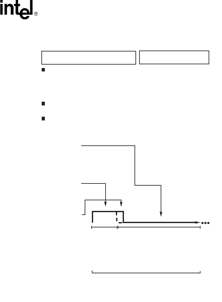
Voice API Programming Guide — June 2005 159
Global Tone Detection and Generation, and Cadenced Tone Generation
Figure 19. Example of Custom Cadenced Tone Generation
Signal Description:
Repetition of combined tones
(440 = 480 Hz) ON for 0.8 to
1.2 seconds, followed by 440
Hz tone ON for 0.2 seconds,
and tone OFF for 2.7 to 3.3
seconds applied within a power
range of -14.5 to 17.5 dBm.
Note:
Dialogic provides a predefined
set of standard call progress
signals that can be generated
by dx_playtoneEx(). This
example shows how you would
define the Special Audible Ring
Tone 1 as a custom cadence
tone if it were not already in the
standard set as
CP_RINGBACK1_CALLWAIT.
Description of the Cadence
Tome Used in this Example
Define the Signal as a
Dialogic Custom Cadence Tome
Set the TN_GENCAD Parameters
tngencad.cycles = 255;
tngencad.numsegs = 2;
tngencad.offtime (0) = 0;
tngencad.offtime (1) = 300;
dx_bidtngen(&tgencad.tone(0),440, 480, -16, -16,
100)
Call thhe dx_playtoneEx( )
dx_playtoneEx (dxxxdev, &tngencad, tpt, EV_SYNC)
TN_GENCAD tngencad
cycles = 255
numsegs = 2
offtime(0) = 0
offtime(1) = 300
offtime(2) = 0
offtime(3) = 0
TN_GEN tone (0)
dflag(0) = 0
tgfreq1(0) = 440
tgfreq2(0) = 480
tg_amp11(0) = -16
tg_amp12(0) = -16
tg_dur(0) = 100
TN_GEN tone (1)
dflag(1) = 0
tgfreq1(1) = 440
tgfreq2(1) = 0
tg_amp11(1) = -16
tg_amp12(1) = 0
tg_dur(1) = 20
TN_GEN tone (2)
dflag(2) = 0
tgfreq1(2) = 0
tgfreq2(2) = 0
tg_amp11(2) = 0
tg_amp12(2) = 0
tg_dur(2) = 0
TN_GEN tone (3)
dflag(3) = 0
tgfreq1(3) = 0
tgfreq2(3) = 0
tg_amp11(3) = 0
tg_amp12(3) = 0
tg_dur(3) = 0
The TN_GENCAD Definition and
Resulting Signal
Segment 1
440 = 480 Hz
dual tone at -16
dB with on-time
of 100 (10ms
units)
and no
off time.
Segment 2
SIngle tone of 440 Hz at
-16 dB with on-time of
20 (10ms units) and off-
time of 300 (or 3
Cycle:
2 segments repeating indefinitely, or until a tpt termination
occurs.
440+480
Hz
100 20
440
Hz
-16
dB
300

160 Voice API Programming Guide — June 2005
Global Tone Detection and Generation, and Cadenced Tone Generation
13.3.3 How To Generate a Non-Cadenced Tone
Both dx_playtoneEx( ) and dx_playtone( ) can generate a non-cadenced tone.
Non-cadenced call progress signals can be generated by the dx_playtone( ) function if you define
them in a TN_GEN: Dial Tone, Executive Override Tone, and Busy Verification Tone Part A.
The dx_playtoneEx( ) function can also generate a non-cadenced tone by using a TN_GENCAD
data structure that defines a single segment.
If you want to generate a continuous, non-cadenced signal, use a single segment and zero off-time,
and specify 1) an infinite number of cycles, 2) an infinite on-time, or 3) both. (You must also
specify the appropriate termination conditions in a DV_TPT structure or else the tone will never
end). For example:
cycles = 255;
numsegs = 1;
offtime[0] = 0;
tone[0].tg_dur = -1
13.3.4 TN_GENCAD Data Structure - Cadenced Tone Generation
TN_GENCAD is a voice library data structure (dxxxlib.h) that defines a cadenced tone that can be
generated by using the dx_playtoneEx( ) function.
The TN_GENCAD data structure contains a tone array with four elements that are TN_GEN data
structures (Tone Generation Templates). For details on TN_GEN and TN_GENCAD, see the Voice
API Library Reference.
For examples of TN_GENCAD, see the definitions of standard call progress signals in Table 20,
“TN_GENCAD Definitions for Standard PBX Call Progress Signals”, on page 165.
13.3.5 How To Generate a Standard PBX Call Progress Signal
Use the following procedure to generate a standard PBX call progress signal from the predefined
set of standard PBX call progress signals:
1. Select a call progress signal from Table 19, “Standard PBX Call Progress Signals”, on
page 162 and note the signal ID (see also Figure 20, “Standard PBX Call Progress Signals
(Part 1)”, on page 163).
2. Set the termination conditions in a DV_TPT structure.
3. Call the dx_playtoneEx( ) function and specify the signal ID for the tngencadp parameter.
For example:
dx_playtoneEx(dxxxdev, CP_BUSY, tpt, EV_SYNC)

Voice API Programming Guide — June 2005 161
Global Tone Detection and Generation, and Cadenced Tone Generation
13.3.6 Predefined Set of Standard PBX Call Progress Signals
The following information describes the predefined set of standard PBX call progress signals that
are provided by Intel:
•Table 19, “Standard PBX Call Progress Signals”, on page 162 lists the predefined, standard,
call progress signals and their signal IDs. The signal IDs can be used with the
dx_playtoneEx( ) function to generate the signal. (The #defines for the signal IDs are located
in the dxxxlib.h file.)
•Figure 20, “Standard PBX Call Progress Signals (Part 1)”, on page 163 illustrates the signals
along with their tone specifications and cadences. The signals were divided into two parts so
they could be illustrated to scale while providing sufficient detail. Part 1 uses a smaller scale
than Part 2. (For this reason, the order of the signals is different than in the tables.)
•Table 20, “TN_GENCAD Definitions for Standard PBX Call Progress Signals”, on page 165
lists the TN_GENCAD definitions of the signal cycle and segment definitions for each
predefined call progress signal. These definitions are located in the dxgtd.c file.
•Section 13.3.7, “Important Considerations for Using Predefined Call Progress Signals”, on
page 166 describes what standard was used, how the standard was implemented, information
regarding the signal power levels, usage and other considerations.

162 Voice API Programming Guide — June 2005
Global Tone Detection and Generation, and Cadenced Tone Generation
Table 19. Standard PBX Call Progress Signals
Name Meaning Signal ID (tngencadp)
Dial Tone Ready for dialing CP_DIAL
Reorder Tone (Paths-Busy, All-Trunks-
Busy, Fast Busy)
Call blocked: resources
unavailable
CP_REORDER
Busy Tone (Slow Busy) Called line is busy CP_BUSY
Audible Ring Tone 1 (Ringback Tone) Called party is being alerted CP_RINGBACK1
Audible Ring Tone 2 1 (Slow Ringback
Tone)
Called party is being alerted CP_RINGBACK2
Special Audible Ring Tone 1 1 Called party has Call Waiting
feature and is being alerted
CP_RINGBACK1_CALLWAIT
Special Audible Ring Tone 2 1 Called party has Call Waiting
feature and is being alerted
CP_RINGBACK2_CALLWAIT
Recall Dial Tone Ready for additional dialing on
established connection
CP_RECALL_DIAL
Intercept Tone Call blocked: invalid CP_INTERCEPT
Call Waiting Tone 1 2 Call is waiting: single burst C_CALLWAIT1
Call Waiting Tone 2 2 Call is waiting: double burst CP_CALLWAIT2
Busy Verification Tone (Part A) Alerts parties that attendant is
about to enter connection
CP_BUSY_VERIFY_A
Busy Verification Tone (Part B) Attendant remains connected CP_BUSY_VERIFY_B
Executive Override Tone Overriding party about to be
bridged onto connection
CP_EXEC_OVERRIDE
Confirmation Tone Feature has been activated or
deactivated
CP_FEATURE_CONFIRM
Stutter Dial Tone (Message Waiting
Dial Tone)
Message waiting; ready for dialing CP_STUTTER_DIAL or
CP_MSG_WAIT_DIAL
1Either of the two Audible Ring Tones can be used but are not intended to be intermixed in a system. When using the
Special Audible Ring Tone (1 or 2), it should correspond to the Audible Ring Tone (1 or 2) that is used.
2The two Call Waiting Tones (1 & 2) can be used to differentiate between internally and externally originated calls. Call
Waiting Tone 2 is defined as a double burst in this implementation, although “multiple” bursts are permissible.

Voice API Programming Guide — June 2005 163
Global Tone Detection and Generation, and Cadenced Tone Generation
Figure 20. Standard PBX Call Progress Signals (Part 1)
25
CP_RINGBACK2
440 + 480 Hz
-16 dB
≈
100
≈
400
CP_RINGBACK1
440 + 480 Hz
-16 dB ≈
300
≈
100
CP_BUSY
480 + 620 Hz
-21 dB 50
50
50
50
25
CP_REORDER
480 + 620 Hz
-21 dB 25
25
25
25 25
25
CP_DIAL
350 + 440 Hz
-16 dB
Continuous
CP_RINGBACK2_CALLWAIT
a) 440 + 480 Hz b) 440 Hz
-16 dB 400
20200
≈
440+480
Hz
440
Hz
CP_RINGBACK1_CALLWAIT
a) 440 + 480 Hz b) 440 Hz
-16 dB ≈
300
≈
100 20
440
Hz
440+480
Hz
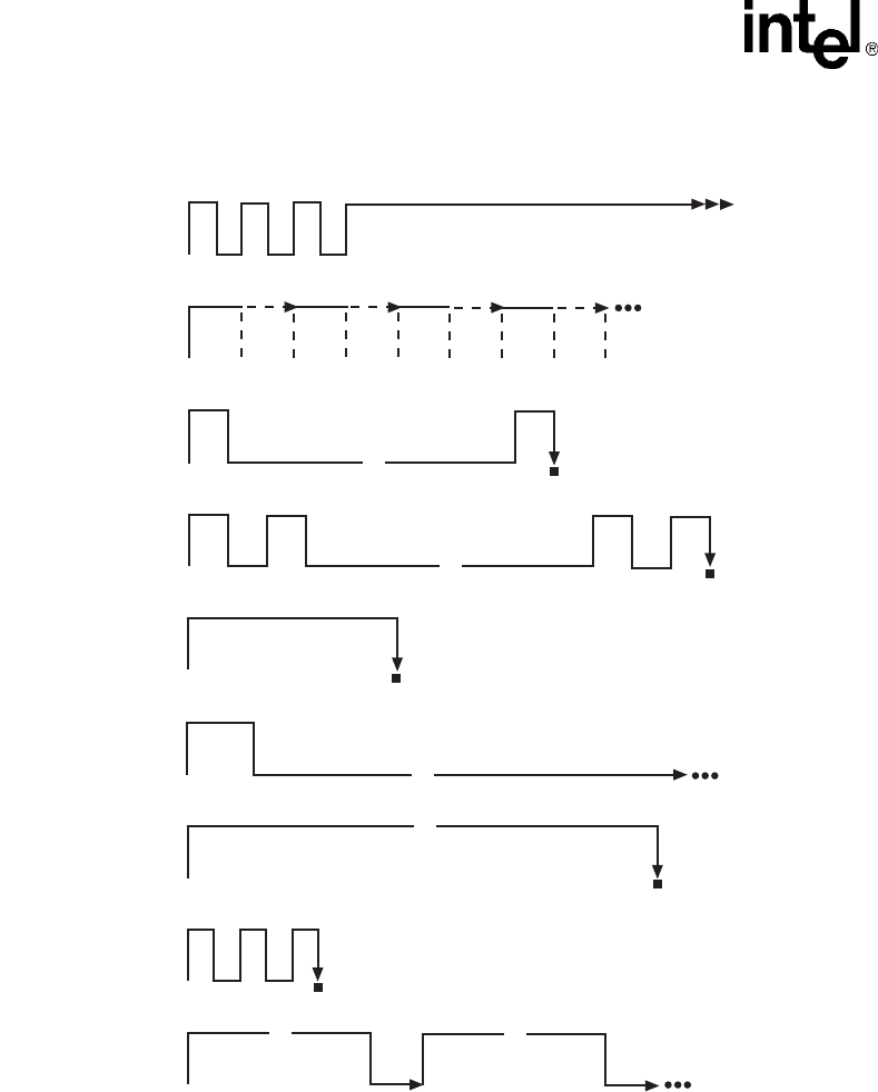
164 Voice API Programming Guide — June 2005
Global Tone Detection and Generation, and Cadenced Tone Generation
Figure 21. Standard PBX Call Progress Signals (Part 2)
continuous
10 10
10 10
10
10
CP_RECALL_DIAL
350 + 440 Hz
-17 db
CP_INTERCEPT
a) 440 Hz + b) 620 Hz
-14 db
CP_CALLWAIT1
440 Hz
-23 db
CP_CALLWAIT2
440 Hz
-23 db
CP_BUSY_VERIFY_A
440 Hz
-14 db
CP_BUSY_VERIFY_B
440 Hz
-14 db
CP_EXEC_OVERRIDE
440 Hz
-14 db
CP_FEATURE_CONFIRM
350 + 440 Hz
-17 db
CP_MSG_WAIT_DIAL or
CP_STUTTER_DIAL
350 + 440 Hz
-17 db
25 25 25 25
440
Hz 620
Hz 440
Hz 620
Hz
25 25
440
Hz 620
Hz
25 25
440
Hz 620
Hz
20
20
1000
=
20
20
20
1000
=
20
20
20
175
60
900
=
300
=
10 10 10
10 10
125
=
25
125
=
25

Voice API Programming Guide — June 2005 165
Global Tone Detection and Generation, and Cadenced Tone Generation
Table 20. TN_GENCAD Definitions for Standard PBX Call Progress Signals
SIGNAL_ID
Cycle Definition Segment Definitions
Number
of
Cycles1
Number of
Segments
in Cycle
Frequency
#1 (Hz)
Frequency
#2 (Hz)
Amplitude
#1 (dB)
Amplitude
#2 (dB)
On-
Time2
(10
msec)
Off-
Time
(10
msec)
cycles numsegs tg_freq1 tg_freq2 tg_ampl1 tg_ampl2 tg_dur offtime
CP_DIAL
1 1 350 440 -17 -17 -1 0
CP_REORDER
255 1 480 620 -21 -21 25 25
CP_BUSY
255 1 480 620 -21 -21 50 50
CP_RINGBACK1
255 1 440 480 -16 -16 100 300
CP_RINGBACK2
255 1 440 480 -16 -16 200 400
CP_RINGBACK1_CALLWAIT
255 2 440
440
480
0
-16
-16
-16
0
100
20
0
300
CP_RINGBACK2_CALLWAIT
255 2 440
440
480
0
-16
-16
-16
0
200
20
0
400
CP_RECALL_DIAL
1 4 350
350
350
350
440
440
440
440
-17
-17
-17
-17
-17
-17
-17
-17
10
10
10
-1
10
10
10
0
CP_INTERCEPT
255 2 440
620
0
0
-14
-14
0
0
25
25
0
0
CP_CALLWAIT1
1 2 440
440
0
0
-23
-23
0
0
20
20
1000
0
CP_CALLWAIT2
1 4 440
440
440
440
0
0
0
0
-23
-23
-23
-23
0
0
0
0
20
20
20
20
20
1000
20
0
1255 specifies an infinite number of cycles (cycles)
2-
1 specifies an infinite tone duration (tg_dur)

166 Voice API Programming Guide — June 2005
Global Tone Detection and Generation, and Cadenced Tone Generation
13.3.7 Important Considerations for Using Predefined Call
Progress Signals
Take into account the following considerations when using the predefined call progress signals:
•Signal definitions are based on the TIA/EIA Standard: Requirements for Private Branch
Exchange (PBX) Switching Equipment, TIA/EIA-464-B, April 1996 (Telecommunications
Industry Association in association with the Electronic Industries Association, Standards and
Technology Department, 2500 Wilson Blvd., Arlington, VA 22201). To order copies, contact
Global Engineering Documents in the USA at 1-800-854-7179 or 1-303-397-7956.
•A separate Line Lockout Warning Tone, which indicates that the station line has been locked
out because dialing took too long or the station failed to disconnect at the end of a call, is not
necessary and is not recommended. You can use the Reorder tone over trunks; or the Intercept,
Reorder, or Busy tone over stations.
•For signals that specify an infinite repetition of the signal cycle (cycles = 255 on Springware or
40 on DM3) or an infinite duration of a tone (tg_dur = -1), you must specify the appropriate
termination conditions in the DV_TPT structure used by dx_playtoneEx( ).
•There may be more than one way to use TN_GENCAD to generate a given signal. For
example, the three bursts of the Confirmation Tone can be created through one cycle
containing three segments (as in the Intel implementation) or through a single segment that is
repeated in three cycles.
CP_BUSY_VERIFY_A
1 1 440 0 -14 0 175 0
CP_BUSY_VERIFY_B
255 1 440 0 -14 0 60 900
CP_EXEC_OVERRIDE
1 1 440 0 -14 0 300 0
CP_FEATURE_CONFIRM
13350
350
350
440
440
440
-17
-17
-17
-17
-17
-17
10
10
10
10
10
0
CP_STUTTER_DIAL or CP_MSG_WAIT_DIAL
255 1 350 440 -17 -17 125 25
Table 20. TN_GENCAD Definitions for Standard PBX Call Progress Signals (Continued)
SIGNAL_ID
Cycle Definition Segment Definitions
Number
of
Cycles1
Number of
Segments
in Cycle
Frequency
#1 (Hz)
Frequency
#2 (Hz)
Amplitude
#1 (dB)
Amplitude
#2 (dB)
On-
Time2
(10
msec)
Off-
Time
(10
msec)
cycles numsegs tg_freq1 tg_freq2 tg_ampl1 tg_ampl2 tg_dur offtime
1255 specifies an infinite number of cycles (cycles)
2-
1 specifies an infinite tone duration (tg_dur)

Voice API Programming Guide — June 2005 167
Global Tone Detection and Generation, and Cadenced Tone Generation
•To generate a continuous, non-cadenced signal, you can use dx_playtoneEx( ) and
TN_GENCAD to specify a single segment with zero off-time and with an infinite number of
cycles and/or an infinite on-time.
Alternatively, you could use dx_playtone( ) and TN_GEN to generate a non-cadenced signal.
The following non-cadenced call progress signals could be generated by the dx_playtone( )
function if you defined them in a TN_GEN: 1) Dial Tone, 2) Executive Override Tone, and 3)
Busy Verification Tone Part A.
•Note that the Intercept Tone consists of alternating single tones.
•Although the TIA/EIA Standard describes the Busy Verification Tone as one signal, the two
segments are separate tones/events: Part A is a single burst almost three times longer than Part
B and it alerts the parties before the attendant intrudes; Part B is a short burst every 9 seconds
continuing as long as the interruption lasts. The TIA/EIA Standard does not define an off-time
between Part A and B. Therefore, the application developer is responsible for implementing
the timing between the two parts of this signal.
•The TIA/EIA Standard specifies the range of permissible power levels per frequency for 1) the
Central Office trunk interface and 2) all other interfaces (including off-premise stations and tie
trunks). The Intel implementation adopted the approximate middle value in the acceptable
range of power levels for applying the signals to the CO trunk interface. These power levels
were more restrictive than those for the other interfaces. According to the following statement
in the TIA/EIA Standard, additional requirements and considerations may apply:
“Studies have shown that the lower level tones that are transmitted over trunks should be 6 dB
hotter at the trunk interface (than at the line interface) to compensate for increased loss on the
end-to-end connection. In the case of tones used at higher levels, the 6 dB difference is not
used since power at trunk interfaces must be limited to -13 dBm0 total when averaged over any
3-second interval to prevent carrier overload. Maximum permissible powers listed are
consistent with this requirement taking into account the allowable interruption rates for the
various tones. Uninterrupted tones, such as Dial Tone and Intercept Tone, shall be
continuously limited to -13 dBm.”
For related power level information, see also Note 1 for Tables 29 and 30, Section 5.9, and
Section 6.3.5.

168 Voice API Programming Guide — June 2005
Global Tone Detection and Generation, and Cadenced Tone Generation

Voice API Programming Guide — June 2005 169
14
14.Global Dial Pulse Detection
Global dial pulse detection (global DPD) is a signaling component of the voice library. The
following topics provide more information on global DPD:
•Key Features . . . . . . . . . . . . . . . . . . . . . . . . . . . . . . . . . . . . . . . . . . . . . . . . . . . . . . . . . 169
•Global DPD Parameters. . . . . . . . . . . . . . . . . . . . . . . . . . . . . . . . . . . . . . . . . . . . . . . . . 170
•Enabling Global DPD . . . . . . . . . . . . . . . . . . . . . . . . . . . . . . . . . . . . . . . . . . . . . . . . . . 170
•Global DPD Programming Considerations . . . . . . . . . . . . . . . . . . . . . . . . . . . . . . . . . . 171
•Retrieving Digits from the Digit Buffer . . . . . . . . . . . . . . . . . . . . . . . . . . . . . . . . . . . . 171
•Retrieving Digits as Events . . . . . . . . . . . . . . . . . . . . . . . . . . . . . . . . . . . . . . . . . . . . . . 172
•Dial Pulse Detection Digit Type Reporting . . . . . . . . . . . . . . . . . . . . . . . . . . . . . . . . . . 172
•Defines for Digit Type Reporting . . . . . . . . . . . . . . . . . . . . . . . . . . . . . . . . . . . . . . . . . 172
•Global DPD Programming Procedure . . . . . . . . . . . . . . . . . . . . . . . . . . . . . . . . . . . . . . 173
•Global DPD Example Code. . . . . . . . . . . . . . . . . . . . . . . . . . . . . . . . . . . . . . . . . . . . . . 173
14.1 Key Features
Global dial pulse detection is not supported on DM3 boards.
Dial Pulse Detection (DPD) allows applications to detect dial pulses from rotary or pulse phones by
detecting the audible clicks produced when a number is dialed, and to use these clicks as if they
were DTMF digits. Intel global dial pulse detection, called global DPD, is a software-based dial
pulse detection method that can use country-customized parameters for extremely accurate
performance.
Global DPD provides the following features and benefits:
•The global DPD algorithm is adaptive and can train on any DPD digit it encounters, with the
greatest accuracy produced from training on a digit that has 5 or more pulses. Global DPD
does not require a leading “0” to train the global DPD algorithm.
•Global DPD can be performed simultaneously with DTMF detection. The application can
determine whether the digit detected is a DTMF or DPD digit.
•Global DPD can be performed simultaneously with Global Tone Detection (GTD). For
example, the application can use GTD to monitor for dial tone or busy tones simultaneously
with DPD.
•Global DPD supports pulse-digit cut-through during a voice playback, with the correct digit
returned in the digit buffer. Global DPD uses echo cancellation, which provides more accurate
reporting of digits during voice playback.

170 Voice API Programming Guide — June 2005
Global Dial Pulse Detection
•The application can enable global DPD and volume control. (Previously, there was a
restriction that DPD digits had to be sent to the event queue instead of the digit queue if
volume control was enabled.)
The following applications are supported by the global DPD feature:
•Analog applications using the loop-start telephone interface on a supported voice board
•Digital applications using a supported voice board
See the Release Guide for information on boards that support the global DPD feature.
14.2 Global DPD Parameters
This implementation of dial pulse detection is referred to as global DPD because its detection
algorithm supports a wide range of dial pulses, from 8 pulse-per-second (PPS) to 22 PPS
telephones.
Intel is continually qualifying its dial pulse detection algorithm against dial pulse data collected
from different parts of the world to improve DPD accuracy for telephone systems and telephones in
different regions. As appropriate, Intel will issue download parameters from time to time to
improve the accuracy of DPD in a given region of the world, whether it is part of a country, an
entire country, or a group of countries.
On Linux, these parameters are contained in the voice.prm file. To download the global DPD
parameters, select a specific country when the boards are configured.
On Windows, customized global DPD download parameters are provided for several countries such
as Argentina, Brazil, Colombia, India, Japan, Mexico and Venezuela, one of which can be selected
during installation (refer to the Country Specific Parameter File). As additional regions are
qualified for customized global DPD, relevant region-specific support will be released.
Support for a generic 10 pulse-per-second (PPS) global DPD parameter file is provided for
countries that use 10 PPS phones.
You must install the Country-Specific Parameters and select a country to obtain support for global
DPD.
14.3 Enabling Global DPD
On Windows, Global DPD works only on DPD-enabled boards. You must order a separate GDPD
enablement package from Intel to enable GDPD on these boards. See the Release Guide for
information on boards that support the global DPD feature. To indicate that a board is DPD-
enabled, apply the sticker provided with the GDPD enablement package to your board.
Additionally, it is recommended that you write down the serial number of the DPD-enabled board
for your records.

Voice API Programming Guide — June 2005 171
Global Dial Pulse Detection
Global DPD must be implemented on a call-by-call basis. Global DPD uses the dx_setdigtyp( )
function to enable DPD. See the Voice API Library Reference for information on all functions and
data structures described in this chapter.
For any digit detected, you can determine the digit type such as DTMF or DPD by using the
DV_DIGIT data structure in the application. When a dx_getdig( ) or dx_getdigEx( ) function call
is performed, the digits are collected from the firmware and transferred to the user’s digit buffer.
The digits are stored as an array inside the DV_DIGIT structure.
You then use a pointer to the structure that contains a digit buffer. For an example, see
Section 14.10, “Global DPD Example Code”, on page 173. This method allows you to determine
very quickly whether a pulse or DTMF telephone is being used.
14.4 Global DPD Programming Considerations
The global DPD algorithm will accurately detect digits in the supported regions without requesting
a special training digit from the caller or requiring any other restrictions on the application.
However, observe the following considerations when designing the application:
•Talk-off rejection (the ability of the algorithm to distinguish between dial pulses and the
human voice) will improve after the first digit is detected.
•Digit detection will be slightly more accurate (about 2%) after detecting a digit of 5 or greater.
It is not necessary to dial a special training digit to do this. The application may simply restrict
the first menu to digits 5, 6, 7, 8, 9, and 0, and the training will be complete. Subsequent menus
may be unrestricted.
•In general, detection accuracy is greater for higher digits than for lower. While detection
accuracy is very high, it may be further improved by restricting menu selections, whenever
convenient, to digits greater than 3.
14.5 Retrieving Digits from the Digit Buffer
To get the digits from the digit buffer, use the following synchronous programming model:
1. Define a data structure of type DV_DIGIT (the DV_DIGIT structure is defined by including
the dxxxlib.h header file).
2. Enable DPD on the desired channels using the dx_setdigtyp( ) function.
3. For each new connection, use dx_setdigtyp( ) with the D_DPDZ mask, which initializes the
DPD algorithm. After collecting the first DPD digit string, the mask can be set to D_DPD for
the remainder of that connection. Each subsequent invocation of dx_setdigtyp( ) must use the
D_DPD mask.
4. Execute the dx_getdig( ) function to collect and transfer the digits to the user’s digit buffer.
The digits are stored in the dg_value field of the DV_DIGIT structure. The corresponding digit
types (dial pulse, DTMF, and so on) are stored in the dg_type field of the DV_DIGIT structure.
For more information, see the DV_DIGIT structure in the Voice API Library Reference.

172 Voice API Programming Guide — June 2005
Global Dial Pulse Detection
14.6 Retrieving Digits as Events
To get the digits as events, use the following asynchronous programming model using the
dx_setevtmsk( ), sr_waitevt( ), and sr_getevtdatap( ) functions and the DX_CST data structure.
1. Since the supported voice boards come with channels capable of global DPD, you must enable
DPD on the desired channels using the dx_setdigtyp( ) function.
2. For each new connection, use dx_setdigtyp( ) with the D_DPDZ mask, which initializes the
DPD algorithm. After collecting the first DPD digit string, the mask can be set to D_DPD for
the remainder of that connection. Each subsequent invocation of dx_setdigtyp( ) must use the
D_DPD mask.
3. Use dx_setevtmsk( ) to enable digit detection.
4. Use sr_waitevt( ) to wait for events.
5. When a CST event occurs, use sr_getevtdatap( ) to retrieve the pointer to the DX_CST
structure.
6. The cst_data field (DX_CST structure) for a DE_DIGITS event contains an ASCII digit (low
byte) and the digit type (high byte). For more information, see the DX_CST structure in the
Voice API Library Reference.
14.7 Dial Pulse Detection Digit Type Reporting
Two defines are provided for identifying the dial pulse detection digit type, depending upon how
the digit type is retrieved:
DG_DPD
Dial pulse detection digit from the DX_EBLK event queue data (cst_data) through a
DE_DIGITS Call Status Transition event
DG_DPD_ASCII
Dial pulse detection digit from the DV_DIGIT dg_type digit buffer using dx_getdig( )
Obtaining the digit type for DPD digits is valid only in the case when the voice and DPD
capabilities are both present on the same board. In the case where a voice board does not support
DPD, you cannot detect DPD digits or obtain the DPD digit type even though you can enable DPD
and digit type reporting without an error.
14.8 Defines for Digit Type Reporting
Use the defines as shown here to determine the digit type from the value returned in the dg_type
(digit type) field from the DV_DIGIT digit buffer. If you get the digit from the DV_DIGIT dg_type
digit buffer using dx_getdig( ), you should use the digit type define that has the “_ASCII” suffix.
Otherwise, if you get the digit from the DX_EBLK event queue data (cst_data) through a
DE_DIGITS Call Status Transition event, you should use the digit type define without the
“_ASCII” suffix.

Voice API Programming Guide — June 2005 173
Global Dial Pulse Detection
14.9 Global DPD Programming Procedure
Use the following procedure to implement global DPD:
1. Define a data structure of type DV_DIGIT (this structure is specified in the DXDIGIT.H file).
2. Enable DPD on the desired channels using the dx_setdigtyp( ) function. For new calls you
must use the D_DPDZ mask that initializes the DPD detector for new calls.
3. Execute the dx_getdig( ) function to collect and transfer the digits to the user’s digit buffer.
The digits are stored in the dg_value field of the DV_DIGIT structure with the corresponding
digit types stored in the dg_type field of the DV_DIGIT structure.
14.10 Global DPD Example Code
The following example illustrates how to set up and use global DPD. The code uses the
synchronous model.
/*$ dx_setdigtyp( )and dx_getdig( ) example for global dial pulse detection $*/
#include <stdio.h>
#include "srllib.h"
#include "dxxxlib.h"
void main(int argc, char **argv)
{
int dev; /* Dialogic device handle */
DV_DIGIT dig;
DV_TPT tpt;
/*
* Open device, make or accept call
*/
/* set up TPT to wait for 3 digits and terminate */
dx_clrtpt(&tpt, 1);
tpt.tp_type = IO_EOT;
tpt.tp_termno = DX_MAXDTMF;
tpt.tp_length = 3;
tpt.tp_flags = TF_MAXDTMF;
Defines for dg_type from
Digit Type Digit Buffer Event Queue
DTMF DG_DTMF_ASCII DG_DTMF
DPD DG_DPD_ASCII DG_DPD
MF DG_MF_ASCII DG_MF
GTD DG_USER1_ASCII DG_USER1
(user-defined) DG_USER2_ASCII DG_USER2
DG_USER3_ASCII DG_USER3
DG_USER4_ASCII DG_USER4
DG_USER5_ASCII DG_USER5

174 Voice API Programming Guide — June 2005
Global Dial Pulse Detection
/* enable DPD and DTMF digits */
dx_setdigtyp(dev, D_DPDZ|D_DTMF);
/* clear the digit buffer */
dx_clrdigbuf(dev);
/* collect 3 digits from the user */
if (dx_getdig(dev, &tpt, &dig, EV_SYNC) == -1) {
/* error, display error message */
printf("dx_getdig error %d, %s\n", ATDV_LASTERR(dev), ATDV_ERRMSGP(dev));
} else {
/* display digits received and digit type */
printf("Received \"%s\"\n", dig.dg_value);
printf("Digit type is ");
/*
* digit types have 0x30 ORed with them strip it off
* so that we can use the DG_xxx equates from the header files
*/
switch ((dig.dg_type[0] & 0x000f)) {
case DG_DTMF:
printf("DTMF\n");
break;
case DG_DPD:
printf("DPD\n");
break;
default:
printf("Unknown, %d\n", (dig.dg_type[0] &0x000f));
}
}
/*
* continue processing call
*/

Voice API Programming Guide — June 2005 175
15
15.R2/MF Signaling
This chapter provides a description of R2/MF signaling protocol. The following topics are
presented:
•R2/MF Overview . . . . . . . . . . . . . . . . . . . . . . . . . . . . . . . . . . . . . . . . . . . . . . . . . . . . . . 175
•Direct Dialing-In Service. . . . . . . . . . . . . . . . . . . . . . . . . . . . . . . . . . . . . . . . . . . . . . . . 176
•R2/MF Multifrequency Combinations . . . . . . . . . . . . . . . . . . . . . . . . . . . . . . . . . . . . . 176
•R2/MF Signal Meanings . . . . . . . . . . . . . . . . . . . . . . . . . . . . . . . . . . . . . . . . . . . . . . . . 177
•R2/MF Compelled Signaling. . . . . . . . . . . . . . . . . . . . . . . . . . . . . . . . . . . . . . . . . . . . . 183
•R2/MF Voice Library Functions . . . . . . . . . . . . . . . . . . . . . . . . . . . . . . . . . . . . . . . . . . 185
•R2/MF Tone Detection Template Memory Requirements . . . . . . . . . . . . . . . . . . . . . . 186
15.1 R2/MF Overview
R2/MF signaling is an international signaling system that is used in Europe and Asia to permit the
transmission of numerical and other information relating to the called and calling subscribers’
lines.
Note: R2/MF signaling is typically accomplished through the Global Call API. For more information, see
the Global Call documentation set. The information in this chapter is provided for reference
purposes only. It is not recommended that the voice library functions described in this chapter be
used for R2/MF signaling.
R2/MF signals that control the call setup are referred to as interregister signals. In the case of the
signals sent between the central office (CO) and the customer premises equipment (CPE), the CO is
referred to as the outgoing register and the CPE as the incoming register. Signals sent from the
CO are forward signals; signals sent from the CPE are backward signals. The outgoing register
(CO) sends forward interregister signals and receives backward interregister signals. The incoming
register (CPE) receives forward interregister signals and sends backward interregister signals. See
Figure 22.
Figure 22. Forward and Backward Interregister Signals
The focus of this section is on the forward and backward interregister signals, and more
specifically, the address signals, which can provide the telephone number of the called
subscriber’s line. For national traffic, the address signals can also provide the telephone number of
a calling subscriber’s line for automatic number identification (ANI) applications.
Forward Signal
Outgoing
Register
(CO)
Incoming
Register
(CPE)
Backward Signal

176 Voice API Programming Guide — June 2005
R2/MF Signaling
R2/MF signals that are used for supervisory signaling on the network are called line signals. Line
signals are beyond the scope of this document.
15.2 Direct Dialing-In Service
Since R2/MF address signals can provide the telephone number of the called subscriber’s line, the
signals may be used by applications providing direct dialing-in (DDI) service, also known as direct
inward dialing (DID), and dialed number identification service (DNIS).
DDI service allows an outside caller to dial an extension within a company without requiring an
operator to transfer the call. The central office (CO) passes the last 2, 3, or 4 digits of the dialed
number to the customer premises equipment (CPE) and the CPE completes the call.
15.3 R2/MF Multifrequency Combinations
R2/MF signaling uses a multifrequency code system based on six fundamental frequencies in the
forward direction (1380, 1500, 1620, 1740, 1860, and 1980 Hz) and six frequencies in the
backward direction (1140, 1020, 900, 780, 660, and 540 Hz).
Each signal is composed of two out of the six fundamental frequencies, which results in 15
different tone combinations in each direction. Although R2/MF is designed for operation on
international networks with 15 multifrequency combinations in each direction, in national networks
it can be used with a reduced number of signaling frequencies (for example, 10 multifrequency
combinations). See Table 21 and Table 22 for lists of the signal tone pairs.
Table 21. Forward Signals, CCITT Signaling System R2/MF tones
R2/MF TONES INTEL INFORMATION
Tone Number Tone Pair Frequencies
(Hz)
Group I
Define
Group II
Define
Tone Detect.
ID
1 1380 1500 SIGI_1 SIGII_1 101
2 1380 1620 SIGI_2 SIGII_2 102
3 1500 1620 SIGI_3 SIGII_3 103
4 1380 1740 SIGI_4 SIGII_4 104
5 1500 1740 SIGI_5 SIGII_5 105
6 1620 1740 SIGI_6 SIGII_6 106
7 1380 1860 SIGI_7 SIGII_7 107
8 1500 1860 SIGI_8 SIGII_8 108
9 1620 1860 SIGI_9 SIGII_9 109
10 1740 1860 SIGI_0 SIGII_0 110
11 1380 1980 SIGI_11 SIGII_11 111
12 1500 1980 SIGI_12 SIGII_12 112

Voice API Programming Guide — June 2005 177
R2/MF Signaling
15.4 R2/MF Signal Meanings
There are two groups of meanings associated with each set of signals. Group I meanings and Group
II meanings are associated with the 15 forward signals. Group A meanings and Group B meanings
are associated with the 15 backward signals. See Figure 23.
13 1620 1980 SIGI_13 SIGII_13 113
14 1740 1980 SIGI_14 SIGII_14 114
15 1860 1980 SIGI_15 SIGII_15 115
Table 22. Backward Signals, CCITT Signaling System R2/MF tones
R2/MF TONES INTEL INFORMATION
Tone Number Tone Pair
Frequencies (Hz) Group A Define Group B Define
1 1140 1020 SIGA_1 SIGB_1
2 1140 900 SIGA_2 SIGB_2
3 1020 900 SIGA_3 SIGB_3
4 1140 780 SIGA_4 SIGB_4
5 1020 780 SIGA_5 SIGB_5
6 900 780 SIGA_6 SIGB_6
7 1140 660 SIGA_7 SIGB_7
8 1020 660 SIGA_8 SIGB_8
9 900 660 SIGA_9 SIGB_9
10 780 660 SIGA_0 SIGB_0
11 1140 540 SIGA_11 SIGB_11
12 1020 540 SIGA_12 SIGB_12
13 900 540 SIGA_13 SIGB_13
14 780 540 SIGA_14 SIGB_14
15 660 540 SIGA_15 SIGB_15
Table 21. Forward Signals, CCITT Signaling System R2/MF tones (Continued)
R2/MF TONES INTEL INFORMATION
Tone Number Tone Pair Frequencies
(Hz)
Group I
Define
Group II
Define
Tone Detect.
ID

178 Voice API Programming Guide — June 2005
R2/MF Signaling
Figure 23. Multiple Meanings for R2/MF Signals
In general, Group I forward signals and Group A backward signals are used to control the call setup
and to transfer address information between the outgoing register (CO) and the incoming register
(CPE). The incoming register can then signal to the outgoing register to change over to the Group II
and Group B meanings.
Group II forward signals provide the calling party’s category, and Group B backward signals
provide the condition of the called subscriber’s line. For further information, see Table 23,
“Purpose of Signal Groups and Changeover in Meaning”, on page 178 describing the purpose of
the signal groups and the changeover in meanings.
Signaling must always begin with a Group I forward signal followed by a Group A backward signal
that serves to acknowledge the signal just received and also has its own meaning. Each signal then
requires a response from the other party. Each response becomes an acknowledgment of the event
and an event for the other party to respond to.
Backward signals serve to indicate certain conditions encountered during call setup or to announce
switch-over to changed meanings of subsequent backward signals. Changeover to Group II and
Group B meanings allows information about the state of the called subscriber’s line to be
transferred.
Forward
Signals
Backward
Signals
Group I
Meanings
Group II
Meanings
Group A
Meanings
Group B
Meanings
Table 23. Purpose of Signal Groups and Changeover in Meaning
Signal Purpose
Group I Group I signals control the call set-up and provide address information.
Group A Group A signals acknowledge Group I signals (see exception under signal A-5 below) for call
set-up, and can also request address and other information. Group A signals also control the
changeover to Group II and Group B meanings through the following signals:
A-3 Address Complete - Changeover to Reception of Group B Signals: Indicates the
address is complete and signals a changeover to Group II/B meanings; after signal A-3
is sent, signaling cannot change back to Group I/A meanings.
A-5 Send Calling Party’s Category: Requests transmission of a single Group II signal
providing the calling party’s category. Signal A-5 requests a Group II signal but does
not indicate changeover to Group B signals. When the Group II signal requested by
A-5 is received, it is acknowledged by a Group A signal; this is an exception to the rule
that Group A signals acknowledge Group I signals.
Group II Group II signals acknowledge signal A-3 or A-5 and provide the calling party category (national
or international call, operator or subscriber, data transmission, maintenance or test call).
Group B Group B signals acknowledge Group II signals and provide the condition of the called
subscriber’s line. Before Group B signals can be transmitted, the preceding backward signal
must have been A-3. Signals cannot change back to Group I/A.

Voice API Programming Guide — June 2005 179
R2/MF Signaling
The incoming register backward signals can request:
•Transmission of address
–Send next digit
–Send digit previous to last digit sent
–Send second digit previous to last digit sent
–Send third digit previous to last digit sent
•Category of the call (the nature and origin)
–National or international call
–Operator or subscriber
–Data transmission
–Maintenance or test call
•Whether or not the circuit includes a satellite link
•Country code and language for international calls
•Information on use of an echo suppressor
The incoming register backward signals can indicate:
•Address complete - send category of call
•Address complete - put call through
•International, national, or local congestion
•Condition of subscriber’s line
–Send SIT to indicate long-term unavailability
–Line busy
–Unallocated number
–Line free - charge on answer
–Line free - no charge on answer (only for special destinations)
–Line out of order
Note: The meaning of certain forward multifrequency combinations may also vary depending upon their
position in the signaling sequence. For example, with terminal calls the first forward signal
transmitted in international working is a language or discriminating digit (signals I-1 through I-10).
When the same signal is sent as other than the first signal, it usually means a numerical digit.
See the following tables for the signal meanings:
•Table 24, “Meanings for R2/MF Group I Forward Signals”, on page 180
•Table 25, “Meanings for R2/MF Group II Forward Signals”, on page 181
•Table 26, “Meanings for R2/MF Group A Backward Signals”, on page 182
•Table 27, “Meanings for R2/MF Group B Backward Signals”, on page 183

180 Voice API Programming Guide — June 2005
R2/MF Signaling
Table 24. Meanings for R2/MF Group I Forward Signals
Tone
Number Intel Define (A) Primary Meaning (B) Secondary Meaning
1 SIGI_1 (A) Digit 1 (B) Language digit-French
2 SIGI_2 (A) Digit 2 (B) Language digit-English
3 SIGI_3 (A) Digit 3 (B) Language digit-German
4 SIGI_4 (A) Digit 4 (B) Language digit-Russian
5 SIGI_5 (A) Digit 5 (B) Language digit-Spanish
6 SIGI_6 (A) Digit 6 (B) Spare (language digit)
7 SIGI_7 (A) Digit 7 (B) Spare (language digit)
8 SIGI_8 (A) Digit 8 (B) Spare (language digit)
9 SIGI_9 (A) Digit 9 (B) Spare (discriminating digit)
10 SIGI_0 (A) Digit 0 (B) Discriminating digit
11 SIGI_11 (A) Access to incoming operator (Code 11) (B) Country code indicator:
outgoing half-echo suppressor required
12 SIGI_12 (A) Access to delay operator (code 12); request not accepted (B) Country
code indicator: no echo suppressor required
13 SIGI_13 (A) Access to test equipment (code 13); satellite link not included (B) Te s t c a l l
indicator
14 SIGI_14 (A) Incoming half-echo suppressor required; satellite link included
(B) Country code indicator: outgoing half-echo suppressor inserted
15 SIGI_15 (A) End of pulsing (code 15); end of identification (B) Signal not used

Voice API Programming Guide — June 2005 181
R2/MF Signaling
Table 25. Meanings for R2/MF Group II Forward Signals
Tone
Number Intel Define Meaning
1 SIGII_1 National: Subscriber without priority
2 SIGII_2 National: Subscriber with priority
3 SIGII_3 National: Maintenance equipment
4 SIGII_4 National: Spare
5 SIGII_5 National: Operator
6 SIGII_6 National: Data transmission
7 SIGII_7 International: Subscriber, operator, or maintenance equipment (without
forward transfer)
8 SIGII_8 International: Data transmission
9 SIGII_9 International: Subscriber with priority
10 SIGII_0 International: Operator with forward transfer facility
11 SIGII_11 Spare for national use
12 SIGII_12 Spare for national use
13 SIGII_13 Spare for national use
14 SIGII_14 Spare for national use
15 SIGII_15 Spare for national use

182 Voice API Programming Guide — June 2005
R2/MF Signaling
Table 26. Meanings for R2/MF Group A Backward Signals
Tone
Number Intel Define Meaning
1 SIGA_1 Send next digit (n+1)
2 SIGA_2 Send last but one digit (n-1)
3 SIGA_3 Address complete; change to Group B signals; no change back
4 SIGA_4 Congestion in the national network
5 SIGA_5 Send calling party’s category; change to Group II; can change back
6 SIGA_6 Address complete; charge; set up speech conditions
7 SIGA_7 Send last but two digit (n-2)
8 SIGA_8 Send last but three digit (n-3)
9 SIGA_9 Spare for national use
10 SIGA_0 Spare for national use
11 SIGA_11 Send country code indicator
12 SIGA_12 Send language or discriminating digit
13 SIGA_13 Send nature of circuit (satellite link only)
14 SIGA_14 Request for information on use of an echo suppressor
15 SIGA_15 Congestion in an international exchange or at its output

Voice API Programming Guide — June 2005 183
R2/MF Signaling
15.5 R2/MF Compelled Signaling
R2/MF interregister signaling uses forward and backward compelled signaling. Simply put, with
compelled signaling each signal is sent until it is responded to by a return signal, which in turn is
sent until responded to by the other party. Each signal stays on until the other party responds, thus
compelling a response from the other party.
Reliability and speed requirements for signaling systems are often in conflict: the faster the
signaling, the more unreliable it is likely to be. Compelled signaling provides a balance between
speed and reliability because it adapts its signaling speed to the working conditions with a
minimum loss of reliability.
The R2/MF signal is composed of two significant events: tone-on and tone-off. Each tone event
requires a response from the other party. Each response becomes an acknowledgment of the event
and an event for the other party to respond to.
Compelled signaling must always begin with a Group I forward signal.
•The CO starts to send the first forward signal.
•As soon as the CPE recognizes the signal, it starts to send a backward signal that serves as an
acknowledgment and at the same time has its own meaning.
Table 27. Meanings for R2/MF Group B Backward Signals
Tone
Number Intel Define Meaning
1 SIGB_1 Spare for national use
2 SIGB_2 Send special information tone to indicate long-term unavailability
3 SIGB_3 Subscriber line busy
4 SIGB_4 Congestion encountered after change to Group B
5 SIGB_5 Unallocated number
6 SIGB_6 Subscriber line free; charge on answer
7 SIGB_7 Subscriber line free; no charge (only for calls to special destinations)
8 SIGB_8 Subscriber line out of order
9 SIGB_9 Spare for national use
10 SIGB_0 Spare for national use
11 SIGB_11 Spare for national use
12 SIGB_12 Spare for national use
13 SIGB_13 Spare for national use
14 SIGB_14 Spare for national use
15 SIGB_15 Spare for national use

184 Voice API Programming Guide — June 2005
R2/MF Signaling
•As soon as the CO recognizes the CPE acknowledging signal, it stops sending the forward
signal.
•As soon as the CPE recognizes the end of the forward signal, it stops sending the backward
signal.
•As soon as the CO recognizes the CPE end of the backward signal, it may start to send the next
forward signal.
The CPE responds to a tone-on with a tone-on and to a tone-off with a tone-off. The CO responds
to a tone-on with a tone-off and to a tone-off with a tone-on. See Figure 24 and Figure 25 for more
information.
Figure 24. R2/MF Compelled Signaling Cycle
A) CO: Turns Forward Signal ON
B) CPE: Detects Forward Signal ON
Turns Backward SIgnal ON
C) CO: Detects Backward Signal ON
Turns Forward Signal OFF
D) CPE: Detects Forward Signal OFF
Turns Backward SIgnal OFF
E) CO: Detects Backward Signal OFF
Begins Next Signal Cycle
Detected Event Response
Time
CO
Forward
Signal
CO
Backward
Signal
A
B
C
D
OFF
OFF
ON
ON
OFF
OFF
ON
ON
E

Voice API Programming Guide — June 2005 185
R2/MF Signaling
Figure 25. Example of R2/MF Signals for 4-digit DDI Application
15.6 R2/MF Voice Library Functions
The R2/MF voice library functions are not supported on DM3 boards. For R2/MF signaling on
DM3 boards, see the Global Call documentation set.
The voice software support for R2/MF signaling is based on global tone detection and global tone
generation.
The following R2/MF functions allow you to define R2/MF tones for detecting the forward signals
and to play the backward signals in the correct timing sequence required by the compelled
signaling procedure:
r2_creatfsig( )
create R2/MF Forward Signal Tone
r2_playbsig( )
play R2/MF Backward Signal
See the Voice API Library Reference for a detailed description of these functions.
CO Forward Signal
Detected
Event
CPE Backward Signal
Response
Digit 3
Digit 9
Digit 6
Digit 0
B-6
A-3
A-1
A-1
A-1
1-3
1-9
1-6
1-0
Send Next Digit
Send Next Digit
Send Next Digit
Address Complete
Changeover to Group B
Subscriber Line Free
Charge on Answer
II-1
Category of Calling Party:
Subscriber w/o Priority-National

186 Voice API Programming Guide — June 2005
R2/MF Signaling
Four sets of defines are provided to specify the 15 Group I and 15 Group II forward signals, and the
15 Group A and 15 Group B backward signals. For a list of these defines, see Table 24, “Meanings
for R2/MF Group I Forward Signals”, on page 180, Table 25, “Meanings for R2/MF Group II
Forward Signals”, on page 181, Table 26, “Meanings for R2/MF Group A Backward Signals”, on
page 182, and Table 27, “Meanings for R2/MF Group B Backward Signals”, on page 183.
15.7 R2/MF Tone Detection Template Memory
Requirements
To implement R2/MF signaling, the board must have sufficient memory blocks to create the
number of user-defined tones required by your application. Your application may not need to detect
all 15 forward signals, especially if you do not need to support R2/MF signaling for international
calls. If that is the case, your application can work with a reduced number of R2/MF tones.
High-density boards such as D/160SC-LS, D/240JCT-T1, and D/300JCT-E1 normally contain
sufficient memory to create the necessary R2/MF tones. However, you should be aware of the
maximum number of user-defined tones (including non-R2/MF tones) allowed on the board.
Low-density boards such as D/41JCT-LS, D/41H, Dialog/4, and ProLine/2V boards may also be
able to create all 15 R2/MF tones due to the overlap in frequencies for the R2/MF signals. If
creating these tones exceeds the maximum number of tones allowed, you may be able to support
R2/MF signaling through a reduced number of R2/MF user-defined tones.
See Section 13.1.8, “Maximum Amount of Memory for Tone Templates”, on page 152 for more
information.

Voice API Programming Guide 187
16
16.Syntellect License Automated
Attendant
This chapter discusses Intel® hardware and software that include a license for the Syntellect
Technology Corporation (STC) patent portfolio:
•Overview of Automated Attendant Function. . . . . . . . . . . . . . . . . . . . . . . . . . . . . . . . . 187
•Syntellect License Automated Attendant Functions . . . . . . . . . . . . . . . . . . . . . . . . . . . 188
•How to Use the Automated Attendant Function Call . . . . . . . . . . . . . . . . . . . . . . . . . . 188
16.1 Overview of Automated Attendant Function
The information in this chapter does not apply to DM3 boards. In addition, it only applies to
Windows.
As a result of a patent license agreement between Dialogic and Syntellect Technology Corporation
(STC), you can purchase products that are licensed for specific telephony patents held by
Syntellect Technology Corporation directly from Intel. These patents cover a range of common
functions used in computer telephony such as automated attendant, automated access and call
processing to facilitate call completions.
One way to protect yourself from possible patent infringement is by purchasing specific Intel
hardware and software that include a license for the Syntellect Technology Corporation (STC)
patent portfolio. Boards that support the Syntellect License Automated Attendant have “STC”
included in the part number.
By doing so, you participate in a program that covers past, present and future applications. (Any
Intel product that does not contain the “STC” designation in its part number is not licensed under
the STC patent portfolio.)
The Syntellect software is designed to be incorporated into any type of application. If your
application requires patented Syntellect technology, you can use the API function calls in the
Syntellect software to assure that licensed STC-enabled hardware is in the system, and if so, you
can implement the patented functions.
The Syntellect hardware and software package offers a superset of features not available on non-
STC boards. They include:
•a new library of API function calls
•a sample automated attendant application that can be integrated in your voice processing
application. The automated attendant:
–checks for an incoming call
–answers the call and plays a voice file

188 Voice API Programming Guide
Syntellect License Automated Attendant
–receives digit input and transfers the call to the proper extension
•the source code and demonstration code for the automated attendant application
16.2 Syntellect License Automated Attendant Functions
Intel boards that are enabled with the Syntellect Technology Corporation (STC) patent license offer
a new library interface that contains several API functions.
The following functions are described in the Voice API Library Reference:
li_attendant( )
Performs the actions of an automated attendant.
li_islicensed_syntellect( )
Returns TRUE/FALSE value on whether the STC license is enabled on the board.
16.3 How to Use the Automated Attendant Function Call
The li_attendant( ) API performs the actions of an automated attendant. This API operates in loop
forever, synchronous mode and is designed to work in your application as a “created” thread.
To use this function in your application:
•You must provide the address of the li_attendant( ) as the entry point to the system call
_beginthread( ). Do not use createthread( ).
•Before the li_attendant( ) thread can be created, your application must initialize a data
structure providing information for the proper operation of the li_attendant( ) thread. This
data structure, called DX_ATTENDANT, is described in the Voice API Library Reference.
To provide a way to terminate the li_attendant( ) thread, you must define a “named event” in the
data structure. During the initialization process, the API verifies that the data structure contains
valid entries. It checks for the presence of the named event. If the named event exists,
li_attendant( ) continues and runs the automated attendant. If the named event does not exist, an
error is returned. If the channel is on a non-STC board, li_attendant( ) terminates.
For more information on the synchronous programming model, refer to the Standard Runtime
Library API Programming Guide.
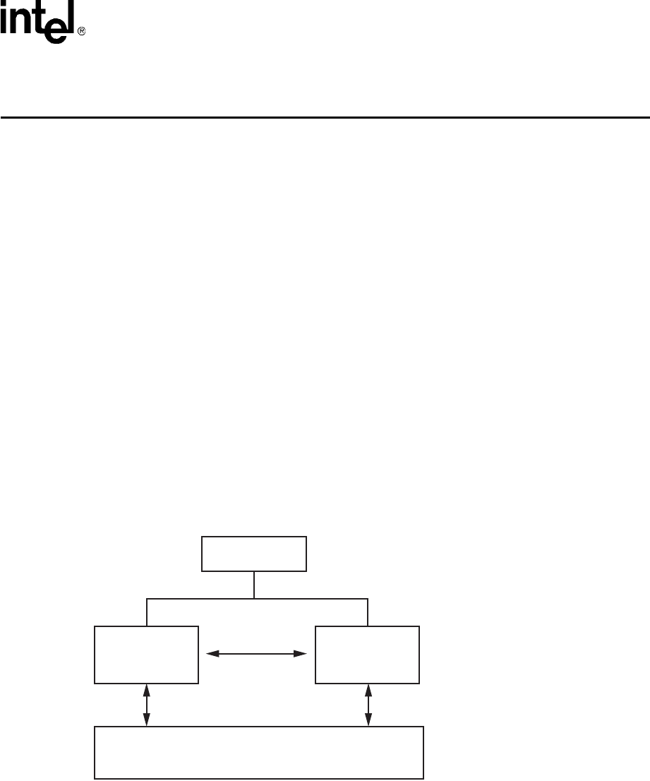
Voice API Programming Guide — June 2005 189
17
17.Building Applications
This chapter provides information on building applications using the voice library. The following
topics are discussed:
•Voice and SRL Libraries . . . . . . . . . . . . . . . . . . . . . . . . . . . . . . . . . . . . . . . . . . . . . . . . 189
•Compiling and Linking . . . . . . . . . . . . . . . . . . . . . . . . . . . . . . . . . . . . . . . . . . . . . . . . . 190
17.1 Voice and SRL Libraries
The C-language application programming interface (API) included with the voice software
provides a library of functions used to create voice processing applications.
The voice library and Standard Runtime Library (SRL) files are part of the voice software. These
libraries provide the interface to the voice driver. For detailed information on the SRL, see the
Standard Runtime Library API Programming Guide and Standard Runtime Library API
Programming Guide.
Figure 26 illustrates how the voice and SRL libraries interface with the driver.
Figure 26. Voice and SRL Libraries
APPLICATION
STANDARD
RUNTIME
LIBRARY
VOICE
LIBRARY
DRIVER

190 Voice API Programming Guide — June 2005
Building Applications
17.2 Compiling and Linking
The following topics discuss compiling and linking requirements:
•Include Files
•Required Libraries
•Run-time Linking
•Variables for Compiling and Linking
17.2.1 Include Files
Function prototypes and equates are defined in include files, also known as header files.
Applications that use voice library functions must contain statements for include files in this form,
where filename represents the include file name:
#include <filename.h>
The following header files must be included in application code in the order shown prior to
calling voice library functions:
srllib.h
Contains function prototypes and equates for the Standard Runtime Library (SRL). Used for
all application development.
dxxxlib.h
Contains function prototypes and equates for the voice library. Used for voice processing
applications.
Note: srllib.h must be included in code before all other Intel header files.
17.2.2 Required Libraries
Simple C language interfaces in source-code format are provided to each individual technology
DLL (such as standard runtime, voice, fax, and network interfaces). These C language interfaces
allow an application to perform run-time linking instead of compile-time linking.
Note: Compile-time linking requires that all functions called in an application be contained in the DLL
that resides on the system.
By default, the library files are located in the directory given by the INTEL_DIALOGIC_LIB
environment variable.
Linux
You must link the following shared object library files in the order shown when compiling your
voice processing application:
libdxxx.so
Main voice library file. Specify -ldxxx in makefile.

Voice API Programming Guide — June 2005 191
Building Applications
libsrl.so
Standard Runtime Library file. Specify -lsrl in makefile.
If you use curses, you must ensure that it is the last library to be linked.
Windows
You must link the following library files in the order shown when compiling your voice
processing application:
libdxxmt.lib
Main voice library file.
libsrlmt.lib
Standard Runtime Library file.
17.2.3 Run-time Linking
This section applies to Windows only.
Run-time linking resolves the entry points to the Intel Dialogic DLLs when the application is
loaded and executed. This allows the application to contain function calls that are not contained in
the DLL that resides on the target system.
To use run-time linking, the application can call the Windows LoadLibrary( ) function to load a
specific technology DLL and a series of GetProcAddress( ) function calls to set up the address
pointers for the functions.
17.2.4 Variables for Compiling and Linking
The following variables provide a standardized way of referencing the directories that contain
header files and shared objects:
INTEL_DIALOGIC_INC
Variable that points to the directory where header files are stored.
INTEL_DIALOGIC_LIB
Variable that points to the directory where shared library files are stored.
These variables are automatically set at login and should be used in compiling and linking
commands. The following is an example of a compiling and linking command that uses these
variables:
cc -I${INTEL_DIALOGIC_INC} -o myapp myapp.c -L${INTEL_DIALOGIC_LIB} -lsrl
Note: It is strongly recommended that you use these variables when compiling and linking applications.
The name of the variables will remain constant, but the values may change in future releases.

192 Voice API Programming Guide — June 2005
Building Applications

Voice API Programming Guide — June 2005 571
Glossary
A-law: Pulse Code Modulation (PCM) algorithm used in digitizing telephone audio signals in E1 areas. Contrast
with mu-law.
ADPCM (Adaptive Differential Pulse Code Modulation): A sophisticated compression algorithm for
digitizing audio that stores the differences between successive samples rather than the absolute value of each
sample. This method of digitization reduces storage requirements from 64 kilobits/second to as low as 24
kilobits/second.
ADSI (Analog Display Services Interface): A Telcordia Technologies (previously Bellcore) standard
defining a protocol for the flow of information between a switch, a server, a voice mail system, a service bureau, or
a similar device and a subscriber’s telephone, PC, data terminal, or other communicating device with a screen.
ADSI adds words to a system that usually only uses touch tones. It displays information on a screen attached to a
phone. ADSI’s signaling is DTMF and standard Bell 202 modem signals from the service to a 202-modem-
equipped phone.
AGC (Automatic Gain Control): An electronic circuit used to maintain the audio signal volume at a constant
level. AGC maintains nearly constant gain during voice signals, thereby avoiding distortion, and optimizes the
perceptual quality of voice signals by using a new method to process silence intervals (background noise).
analog: 1. A method of telephony transmission in which the signals from the source (for example, speech in a
human conversation) are converted into an electrical signal that varies continuously over a range of amplitude
values analogous to the original signals. 2. Not digital signaling. 3. Used to refer to applications that use loop start
signaling.
ANI (Automatic Number Identification): Identifies the phone number that is calling. Digits may arrive in
analog or digital form.
API (Application Programming Interface): A set of standard software interrupts, calls, and data formats that
application programs use to initiate contact with network services, mainframe communications programs, or other
program-to-program communications.
ASCIIZ string: A null-terminated string of ASCII characters.
asynchronous function: A function that allows program execution to continue without waiting for a task to
complete. To implement an asynchronous function, an application-defined event handler must be enabled to trap
and process the completed event. Contrast with synchronous function.
bit mask: A pattern which selects or ignores specific bits in a bit-mapped control or status field.
bitmap: An entity of data (byte or word) in which individual bits contain independent control or status
information.
board device: A board-level object that can be manipulated by a physical library. Board devices can be real
physical boards, such as a D/41JCT-LS, or virtual boards. See virtual board.

572 Voice API Programming Guide — June 2005
board locator technology (BLT): Operates in conjunction with a rotary switch to determine and set non-
conflicting slot and IRQ interrupt-level parameters, thus eliminating the need to set confusing jumpers or DIP
switches.
buffer: A block of memory or temporary storage device that holds data until it can be processed. It is used to
compensate for the difference in the rate of the flow of information (or time occurrence of events) when
transmitting data from one device to another.
bus: An electronic path that allows communication between multiple points or devices in a system.
busy device: A device that has one of the following characteristics: is stopped, being configured, has a
multitasking or non-multitasking function active on it, or I/O function active on it.
cadence: A pattern of tones and silence intervals generated by a given audio signal. The pattern can be classified
as a single ring, a double ring, or a busy signal.
cadence detection: A voice driver feature that analyzes the audio signal on the line to detect a repeating pattern
of sound and silence.
call progress analysis: A process used to automatically determine what happens after an outgoing call is
dialed. On DM3 boards, a further distinction is made. Call progress refers to activity that occurs before a call is
connected (pre-connect), such as busy or ringback. Call analysis refers to activity that occurs after a call is
connected (post-connect), such as voice detection and answering machine detection. The term call progress analysis
is used to encompass both call progress and call analysis.
call status transition event functions: A class of functions that set and monitor events on devices.
caller ID: calling party identification information.
CCITT (Comite Consultatif Internationale de Telegraphique et Telephonique): One of the four
permanent parts of the International Telecommunications Union, a United Nations agency based in Geneva. The
CCITT is divided into three sections: 1. Study Groups set up standards for telecommunications equipment, systems,
networks, and services. 2. Plan Committees develop general plans for the evolution of networks and services. 3.
Specialized Autonomous Groups produce handbooks, strategies, and case studies to support developing countries.
channel: 1. When used in reference to an Intel analog expansion board, an audio path, or the activity happening
on that audio path (for example, when you say the channel goes off-hook). 2. When used in reference to an Intel®
digital expansion board, a data path, or the activity happening on that data path. 3. When used in reference to a bus,
an electrical circuit carrying control information and data.
channel device: A channel-level object that can be manipulated by a physical library, such as an individual
telephone line connection. A channel is also a subdevice of a board. See also subdevice.
CO (Central Office): A local phone network exchange, the telephone company fadcility where subscriber lines
are linked, through switches, to other subscriber lines (including local and long distance lines). The term “Central
Office” is used in North America. The rest of the world calls it “PTT”, for Post, Telephone, and Telegraph.
computer telephony (CT): The extension of computer-based intelligence and processing over the telephone
network to a telephone. Sometimes called computer-telephony integration (CTI), it lets you interact with computer
databases or applications from a telephone, and enables computer-based applications to access the telephone

Voice API Programming Guide — June 2005 573
network. Computer telephony technology supports applications such as: automatic call processing; automatic
speech recognition; text-to-speech conversion for information-on-demand; call switching and conferencing; unified
messaging, which lets you access or transmit voice, fax, and e-mail messages from a single point; voice mail and
voice messaging; fax systems, including fax broadcasting, fax mailboxes, fax-on-demand, and fax gateways;
transaction processing, such as Audiotex and Pay-Per-Call information systems; and call centers handling a large
number of agents or telephone operators for processing requests for products, services, or information.
configuration file: An unformatted ASCII file that stores device initialization information for an application.
convenience function: A class of functions that simplify application writing, sometimes by calling other,
lower-level API functions.
CPE: customer premise equipment.
CT Bus: Computer Telephony bus. A time division multiplexing communications bus that provides 4096 time
slots for transmission of digital information between CT Bus products. See TDM bus.
data structure: Programming term for a data element consisting of fields, where each field may have a different
type definition and length. A group of data structure elements usually share a common purpose or functionality.
DCM: configuration manager. On Windows only, a utility with a graphical user interface (GUI) that enables you to
add new boards to your system, start and stop system service, and work with board configuration data.
debouncing: Eliminating false signal detection by filtering out rapid signal changes. Any detected signal change
must last for the minimum duration as specified by the debounce parameters before the signal is considered valid.
Also known as deglitching.
deglitching: See debouncing.
device: A computer peripheral or component controlled through a software device driver. An Intel voice and/or
network interface expansion board is considered a physical board containing one or more logical board devices, and
each channel or time slot on the board is a device.
device channel: An Intel voice data path that processes one incoming or outgoing call at a time (equivalent to
the terminal equipment terminating a phone line).
device driver: Software that acts as an interface between an application and hardware devices.
device handle: Numerical reference to a device, obtained when a device is opened using xx_open( ), where xx is
the prefix defining the device to be opened. The device handle is used for all operations on that device.
device name: Literal reference to a device, used to gain access to the device via an xx_open( ) function, where
xx is the prefix defining the device to be opened.
digitize: The process of converting an analog waveform into a digital data set.
DM3: Refers to Intel mediastream processing architecture, which is open, layered, and flexible, encompassing
hardware as well as software components. A whole set of products from Intel are built on the Intel® DM3™
architecture. Contrast with Springware, which is earlier-generation architecture.

574 Voice API Programming Guide — June 2005
download: The process where board level program instructions and routines are loaded during board
initialization to a reserved section of shared RAM.
downloadable Springware firmware: Software features loaded to Intel voice hardware. Features include
voice recording and playback, enhanced voice coding, tone detection, tone generation, dialing, call progress
analysis, voice detection, answering machine detection, speed control, volume control, ADSI support, automatic
gain control, and silence detection.
driver: A software module which provides a defined interface between an application program and the firmware
interface.
DSP (Digital Signal Processor): A specialized microprocessor designed to perform speedy and complex
operations on digital signals.
DTMF (Dual-Tone Multi-Frequency): Push-button or touch-tone dialing based on transmitting a high- and a
low-frequency tone to identify each digit on a telephone keypad.
E1: A CEPT digital telephony format devised by the CCITT, used in Europe and other countries around the world.
A digital transmission channel that carries data at the rate of 2.048 Mbps (DS-1 level). CEPT stands for the
Conference of European Postal and Telecommunication Administrations. Contrast with T1.
echo: The component of an analog device’s receive signal reflected into the analog device’s transmit signal.
echo cancellation: Removal of echo from an echo-carrying signal.
emulated device: A virtual device whose software interface mimics the interface of a particular physical device,
such as a D/4x boards that is emulated by a D/12x board. On a functional level, a D/12x board is perceived by an
application as three D/4x boards. Contrast with physical device.
event: An unsolicited or asynchronous message from a hardware device to an operating system, application, or
driver. Events are generally attention-getting messages, allowing a process to know when a task is complete or
when an external event occurs.
event handler: A portion of an application program designed to trap and control processing of device-specific
events.
extended attribute functions: A class of functions that take one input parameter (a valid Intel device handle)
and return device-specific information. For instance, a voice device’s extended attribute function returns
information specific to the voice devices. Extended attribute function names are case-sensitive and must be in
capital letters. See also standard runtime library (SRL).
firmware: A set of program instructions that reside on an expansion board.
firmware load file: The firmware file that is downloaded to a voice board.
flash: A signal generated by a momentary on-hook condition. This signal is used by the voice hardware to alert a
telephone switch that special instructions will follow. It usually initiates a call transfer. See also hook state.
frequency shift keying (FSK): A frequency modulation technique used to send digital data over voice band
telephone lines.

Voice API Programming Guide — June 2005 575
G.726: An international standard for encoding 8 kHz sampled audio signals for transmission over 16, 24, 32 and
40 kbps channels. The G.726 standard specifies an adaptive differential pulse code modulation (ADPCM) system
for coding and decoding samples.
GSM (Global System for Mobile Communications): A digital cellular phone technology based on time
division multiple access (TDMA) used in Europe, Japan, Australia and elsewhere around the world.
hook state: A general term for the current line status of the channel: either on-hook or off-hook. A telephone
station is said to be on-hook when the conductor loop between the station and the switch is open and no current is
flowing. When the loop is closed and current is flowing, the station is off-hook. These terms are derived from the
position of the old fashioned telephone set receiver in relation to the mounting hook provided for it.
hook switch: The circuitry that controls the on-hook and off-hook state of the voice device telephone interface.
I/O: Input-Output
idle device: A device that has no functions active on it.
in-band: The use of robbed-bit signaling (T1 systems only) on the network. The signaling for a particular channel
or time slot is carried within the voice samples for that time slot, thus within the 64 kbps (kilobits per second) voice
bandwidth.
in-band signaling: (1) In an analog telephony circuit, in-band refers to signaling that occupies the same
transmission path and frequency band used to transmit voice tones. (2) In digital telephony, in-band means
signaling transmitted within an 8-bit voice sample or time slot, as in T1 “robbed-bit” signaling.
kernel: A set of programs in an operating system that implement the system’s functions.
loop: The physical circuit between the telephone switch and the voice processing board.
loop current: The current that flows through the circuit from the telephone switch when the voice device is off-
hook.
loop current detection: A voice driver feature that returns a connect after detecting a loop current drop.
loop start: In an analog environment, an electrical circuit consisting of two wires (or leads) called tip and ring,
which are the two conductors of a telephone cable pair. The CO provides voltage (called “talk battery” or just
“battery”) to power the line. When the circuit is complete, this voltage produces a current called loop current. The
circuit provides a method of starting (seizing) a telephone line or trunk by sending a supervisory signal (going
off-hook) to the CO.
loop-start interfaces: Devices, such as an analog telephones, that receive an analog electric current. For
example, taking the receiver off-hook closes the current loop and initiates the calling process.
mu-law: (1) Pulse Code Modulation (PCM) algorithm used in digitizing telephone audio signals in T1 areas. (2)
The PCM coding and companding standard used in Japan and North America. See also A-law.
off-hook: The state of a telephone station when the conductor loop between the station and the switch is closed
and current is flowing. When a telephone handset is lifted from its cradle (or an equivalent condition occurs), the
telephone line state is said to be off-hook. See also hook state.

576 Voice API Programming Guide — June 2005
on-hook: Condition or state of a telephone line when a handset on the line is returned to its cradle (or an
equivalent condition occurs). See also hook state.
PBX: Private Branch Exchange. A small version of the phone company’s larger central switching office. A local
premises or campus switch.
PCM (Pulse Code Modulation): A technique used in DSP voice boards for reducing voice data storage
requirements. Intel supports either mu-law PCM, which is used in North America and Japan, or A-law PCM, which
is used in the rest of the world.
physical device: A device that is an actual piece of hardware, such as a D/4x board; not an emulated device. See
emulated device.
polling: The process of repeatedly checking the status of a resource to determine when state changes occur.
PSTN (or STN): Public (or Private) Switched Telephony Network
resource: Functionality (for example, voice-store-and-forward) that can be assigned to a call. Resources are
shared when functionality is selectively assigned to a call and may be shared among multiple calls. Resources are
dedicated when functionality is fixed to the one call.
resource board: An Intel expansion board that needs a network or switching interface to provide a technology
for processing telecommunications data in different forms, such as voice store-and-forward, speech recognition,
fax, and text-to-speech.
RFU: reserved for future use
ring detect: The act of sensing that an incoming call is present by determining that the telephone switch is
providing a ringing signal to the voice board.
robbed-bit signaling: The type of signaling protocol implemented in areas using the T1 telephony standard. In
robbed-bit signaling, signaling information is carried in-band, within the 8-bit voice samples. These bits are later
stripped away, or “robbed,” to produce the signaling information for each of the 24 time slots.
route: Assign a resource to a time slot.
sampling rate: Frequency at which a digitizer quantizes the analog voice signal.
SCbus (Signal Computing Bus): A hardwired connection between Switch Handlers on SCbus-based
products. SCbus is a third generation TDM (Time Division Multiplexed) resource sharing bus that allows
information to be transmitted and received among resources over 1024 time slots.
SCR: See silence compressed record.
signaling insertion: The signaling information (on hook/off hook) associated with each channel is digitized,
inserted into the bit stream of each time slot by the device driver, and transmitted across the bus to another resource
device. The network interface device generates the outgoing signaling information.
silence compressed record: A recording that eliminates or limits the amount of silence in the recording
without dropping the beginning of words that activate recording.

Voice API Programming Guide — June 2005 577
silence threshold: The level that sets whether incoming data to the voice board is recognized as silence or non-
silence.
SIT: (1) Standard Information Tones: tones sent out by a central office to indicate that the dialed call has been
answered by the distant phone. (2) Special Information Tones: detection of a SIT sequence indicates an operator
intercept or other problem in completing the call.
solicited event: An expected event. It is specified using one of the device library’s asynchronous functions.
Springware: Software algorithms built into the downloadable firmware that provide the voice processing features
available on older-generation Intel® Dialogic® voice boards. The term Springware is also used to refer to a whole
set of boards from Intel built using this architecture. Contrast with DM3, which is a newer-generation architecture.
SRL: See Standard Runtime Library.
standard attribute functions: Class of functions that take one input parameter (a valid device handle) and
return generic information about the device. For instance, standard attribute functions return IRQ and error
information for all device types. Standard attribute function names are case-sensitive and must be in capital letters.
Standard attribute functions for Intel telecom devices are contained in the SRL. See standard runtime library (SRL).
standard runtime library (SRL): An Intel software resource containing event management and standard
attribute functions and data structures used by Intel telecom devices.
station device: Any analog telephone or telephony device (such as a telephone or headset) that uses a loop-start
interface and connects to a station interface board.
string: An array of ASCII characters.
subdevice: Any device that is a direct child of another device. Since “subdevice” describes a relationship
between devices, a subdevice can be a device that is a direct child of another subdevice, as a channel is a child of a
board.
synchronous function: Blocks program execution until a value is returned by the device. Also called a
blocking function. Contrast with asynchronous function.
system release: The software and user documentation provided by Intel that is required to develop applications.
T1: The digital telephony format used in North America and Japan. In T1, 24 voice conversations are time-division
multiplexed into a single digital data stream containing 24 time slots. Signaling data are carried “in-band”; as all
available time slots are used for conversations, signaling bits are substituted for voice bits in certain frames.
Hardware at the receiving end must use the “robbed-bit” technique for extracting signaling information. T1 carries
data at the rate of 1.544 Mbps (DS-1 level).
TDM (Time Division Multiplexing): A technique for transmitting multiple voice, data, or video signals
simultaneously over the same transmission medium. TDM is a digital technique that interleaves groups of bits from
each signal, one after another. Each group is assigned its own time slot and can be identified and extracted at the
receiving end. See also time slot.
TDMA (Time Division Multiple Access): A method of digital wireless communication using time division
multiplexing.

578 Voice API Programming Guide — June 2005
TDM bus: Time division multiplexing bus. A resource sharing bus such as the SCbus or CT Bus that allows
information to be transmitted and received among resources over multiple data lines.
termination condition: An event or condition which, when present, causes a process to stop.
termination event: An event that is generated when an asynchronous function terminates. See also
asynchronous function.
time division multiplexing (TDM): See TDM (Time Division Multiplexing).
time slot: The smallest, switchable data unit on a TDM bus. A time slot consists of 8 consecutive bits of data.
One time slot is equivalent to a data path with a bandwidth of 64 kbps. In a digital telephony environment, a
normally continuous and individual communication (for example, someone speaking on a telephone) is (1)
digitized, (2) broken up into pieces consisting of a fixed number of bits, (3) combined with pieces of other
individual communications in a regularly repeating, timed sequence (multiplexed), and (4) transmitted serially over
a single telephone line. The process happens at such a fast rate that, once the pieces are sorted out and put back
together again at the receiving end, the speech is normal and continuous. Each individual, pieced-together
communication is called a time slot.
time slot assignment: The ability to route the digital information contained in a time slot to a specific analog or
digital channel on an expansion board. See also device channel.
transparent signaling: The mode in which a network interface device accepts signaling data from a resource
device transparently, or without modification. In transparent signaling, outgoing T1 signaling bits are generated by
a TDM bus resource device. In effect the resource device performs signaling to the network.
underrun: data is not being delivered to the board quickly enough which can result in loss of data and gaps in the
audio
virtual board: The device driver views a single physical voice board with more than four channels as multiple
emulated D/4x boards. These emulated boards are called virtual boards. For example, a D/120JCT-LS has 12
channels of voice processing and contains three virtual boards.
voice processing: The science of converting human voice into data that can be reconstructed and played back at
a later time.
voice system: A combination of expansion boards and software that lets you develop and run voice processing
applications.
wink: In T1 or E1 systems, a signaling bit transition from on to off, or off to on, and back again to the original
state. In T1 systems, the wink signal can be transmitted on either the A or B signaling bit. In E1 systems, the wink
signal can be transmitted on either the A, B, C, or D signaling bit. Using either system, the choice of signaling bit
and wink polarity (on-off-on or off-on-off hook) is configurable through DTI/xxx board download parameters.

Voice API Programming Guide — June 2005 201
Index
A
Adaptive Differential Pulse Code Modulation (ADPCM) 91
address signals, R2/MF signaling 175
ADPCM, G.726 91
ADPCM, IMA 90
ADSI_XFERSTRUC data structure 126, 127
A-law PCM 90
Analog Display Services Interface (ADSI) 21, 121
answering machine detection 70
asynchronous programming model 23
ATDV_ERRMSGP( ) 29
ATDV_LASTERR( ) 29
ATDX_CONNTYPE( ) 55, 70
ATDX_CPTERM( ) 47, 61
ATDX_CRTNID( ) 53, 68
ATDX_FRQDUR( ) 75
ATDX_FRQDUR2( ) 76
ATDX_FRQDUR3( ) 76
ATDX_FRQHZ( ) 75
ATDX_FRQHZ2( ) 75
ATDX_FRQHZ3( ) 76
ATDX_TERMMSK( ) 126, 127, 156
B
backward signals (CCITT Signaling System tones) 175, 177
basic call progress analysis 44
beginthread( ) 188
busy state 31
busy tone 162
busy tone detection 53, 68
busy verification tone 162
C
C language interfaces 190
cached prompt management 141
device discovery 141
downloading prompts 142
hints 143
physical board handle 142
playing prompts 142
sample application 144
cadence detection 44, 78
cadenced tone generation 157
custom tone 157
dx_playtoneEx( ) 157
call progress analysis 44
activating, Springware 62
ATDX_CPERROR( ) 60
ATDX_CPTERM( ) 47, 61
busy tone detection 53
call outcomes 49, 63
components 45, 46
dial tone detection 67
disabling, Springware 62
DM3 46
DM3 scenarios 47
DX_CAP parameter structure 48, 61
errors 60
extended attribute functions, DM3 50
extended attribute functions, Springware 64
fax machine detection, DM3 68
fax tone detection, Springware 53
frequency detection 73
errors 76
initiating, DM3 48
initiating, Springware 62
modem detection 53, 68
modifying tone definitions, DM3 57
modifying tone definitions, Springware 71
positive answering machine detection, DM3 55
positive answering machine detection, Springware 70
positive voice detection 70
positive voice detection, DM3 55
ringback detection 52, 67
SIT tones 73
Springware 60
termination results 49, 63
tone definitions 71
tone detection, DM3 51
tone detection, Springware 66
tone template, DM3 56
tone template, Springware 71
tone types 66
tone types, DM3 51
tri-tone frequency detection parameters 73
types 44
use of global tone detection 71
using Global Call API 44
call progress signals, PBX 160

202 Voice API Programming Guide — June 2005
call status transition
event handling
asynchronous 151
synchronous 151
call waiting tone 162
caller ID
accessing information 137
enabling 138
error handling 138
support 135
supported formats 135
CCITT Signaling System R2/MF tones 176
channel
definition 25
CLASS caller ID 135
cluster configuration 36
coders 89
compelled signaling, R2/MF 183
compile-time linking 190
compiling
library files 190, 191
variables 191
CON_CAD connection type 67
CON_LPC connection type 69
CON_PAMD connection type 70
CON_PVD connection type 70
configuration
fixed/flexible routing 35
confirmation tone 162
continuous tone 160
convenience functions
dx_wtcallid( ) 137
speed and volume 113
coupled resources 36
CP_BUSY 162
CP_BUSY_VERIFY_A 162
CP_BUSY_VERIFY_B 162
CP_CALLWAIT1 162
CP_CALLWAIT2 162
CP_DIAL 162
CP_EXEC_OVERRIDE 162
CP_FEATURE_CONFIRM 162
CP_INTERCEPT 162
CP_MSG_WAIT_DIAL 162
CP_RECALL_DIAL 162
CP_REORDER 162, 165
CP_RINGBACK1 162
CP_RINGBACK1_CALLWAIT 162
CP_RINGBACK2 162
CP_RINGBACK2_CALLWAIT 162
CP_STUTTER_DIAL 162
CT Bus 22
curses 191
Custom Local Area Signaling Services 135
D
data formats 89
data structures
clearing 35
DDI (Direct Dialing-In) service 176
DE_WINK event 42
device
definition 25
handle for 25
initializing hint 39
states of 31
device mapper functions 26
device name
definition 25
dial pulse detection 19
see Global DPD 169
dial tone 162
detection 67
dial tone (message waiting) 162
dial tone (recall) 162
dial tone (stutter) 162
Dialed Number Identification Service (DNIS) 176
DID (Direct Inward Dialing) service 176
digitizing methods 89
disabling call progress analysis, Springware 62
DM_WINK 42
DM3
call progress analysis scenarios 47
tone definitions 56
DNIS (Dialed Number Identification Service) 176
DV_DIGIT data structure 171
DV_TPT data structure 126, 127
clearing 35
setting termination conditions 32
dx_addspddig( ) 113
dx_addtone( ) 149
used with global tone detection 148
used with tone templates 150
dx_addvoldig( ) 114
dx_adjsv( ) 114, 118
dx_blddt( ) 149

Voice API Programming Guide — June 2005 203
dx_blddtcad( ) 149
dx_bldst( ) 149
dx_bldstcad( ) 149
dx_bldtngen( ) 156
DX_CAP data structure 48, 61, 70
clearing 35
SIT tone setup 73
dx_chgdur( ) 72
dx_chgfreq( ) 72
dx_chgrepcnt( ) 72
dx_clrcap( ) 35, 48, 61
dx_clrtpt( ) 35
dx_createtone( ) 58
DX_CST data structure 172
dx_deletetone( ) 58
dx_deltones( ) 62
used with tone templates 151
dx_dial( ) 48, 61, 62
DM3 support 47
Springware support 47
dx_distone( ) 151
dx_enbtone( ) 151
dx_getcachesize( ) 142
dx_getdig( ) 34, 118, 171
used with global tone detection 148
dx_getevt( ) 151
dx_getfeaturelist( ) 39, 126, 127
dx_getparm( ) 126
dx_getsvmt( ) 115
dx_getxmitslot( ) 103
dx_getxmitslotecr( ) 103
dx_gtcallid( ) 137
dx_gtextcallid( ) 137
dx_initcallp( ) 61, 62
dx_listen( ) 103
dx_mreciottdata( ) 92
dx_open( ) 39
dx_play( ) 88, 122
dx_playf( ) 88, 122
dx_playiottdata( ) 92
dx_playtone( ) 156
dx_playtoneEx( )
used with cadenced tone generation 157
dx_playvox( ) 88
dx_querytone( ) 57
dx_rec( ) 88, 94
dx_recf( ) 88
dx_reciottdata( ) 92, 95
dx_recm(_) 93
dx_recmf(_) 93
dx_recvox( ) 88
dx_RxIottData( ) 122
dx_RxIottdata( ) 126, 127
dx_setdevuio( ) 35
dx_setdigtyp( ) 171
dx_setevtmsk( ) 42, 151
dx_setgtdamp( ) 149
dx_sethook( ) 42
dx_setparm( ) 126
enabling caller ID 138
dx_setsvcond( ) 114, 118
dx_setsvmt( ) 115, 118
dx_setuio( ) 35
DX_SVCB data structure 118
DX_SVMT data structure 118
dx_TxIottData( ) 122
dx_TxIottdata( ) 126, 127
dx_TxRxIottData( ) 122
dx_TxRxIottdata( ) 126, 127
dx_unlistenecr( ) 103
dx_wtcallid( ) 137
DXBD_OFFHDLY 42
DXCH_MAXRWINK 42
DXCH_MINRWINK 42
DXCH_WINKDLY 41
DXCH_WINKLEN 41
dxxxlib.h 190
E
echo cancellation resource (ECR) 102
application models 105
modes of operation 104
echo component 102
echo reference signal 102
echo-carrying signal 102
ECR 101
ECR mode, echo canceller 104
encoding algorithms 89
G.726 details 91
support in SCR 95
supported for recording with VAD 96
enhanced call progress analysis 18, 44
error handling 29
error handling in caller ID 138

204 Voice API Programming Guide — June 2005
ETSI-FSK channel parameters 126
ETSI-FSK specification 125
event handling 27
event management functions 27
executive override tone 162
extended attribute functions
call progress analysis, DM3 50
call progress analysis, Springware 64
F
fast busy 162
fax machine detection 68
fax tone detection 45, 53
FEATURE_TABLE data structure 126, 127
fixed routing
configuration 35
configuration, restrictions 37
flexible routing
configuration 35
forward signals (CCITT signaling system tones) 175, 176
frequency detection 44, 73
frequency shift keying (FSK) 21, 121
functions
error 29
G
G.711 PCM A-law voice coder 91
G.711 PCM mu-law voice coder 91
G.721 voice coder 90
G.726 bit exact voice coder 90, 91
global dial pulse detection 19, 169
Global DPD
example code 173
getting digits 171, 172
global DPD 19, 169
enabling 171
improving detection 171
global tone detection
applications 155
building tone templates 148
call progress analysis memory usage 76
defining tones 148
definition 147
leading edge detection 155
maximum number of tones 153, 154
multiprocessing considerations 38
R2/MF 185
using with PBX 149
with caller ID 135
global tone generation
cadenced 157
definition 155
R2/MF 185
TN_GEN data structure 156
tone generation template 156
GSM 6.10 full rate voice coder 90, 91
H
header files
voice and SRL 190
hot swap
cached prompts 143
I
I/O functions
terminations 32
idle state 31
IMA ADPCM 90
include files
voice and SRL 190
incoming register 179
incoming register, R2/MF signaling 175
incoming signals, indicating 179
independent resources 36
infinite tone 160
INTEL_DIALOGIC_INC 191
INTEL_DIALOGIC_LIB 191
intercept tone 162
interregister signals, R2/MF signaling 175
L
leading edge detection using debounce time 155
libdxxmt.lib 191
libdxxx.so 190
library files 190, 191

Voice API Programming Guide — June 2005 205
libsrl.so 190
libsrlmt.lib 191
line signals, R2/MF signaling 176
linear PCM 90, 91
linking
library files 190, 191
variables 191
loop current detection 44
parameters affecting a connect 69
use in call progress analysis 69
M
media loads 39
memory requirements, R2/MF 186
message waiting dial tone 162
modem detection 68
modem tone detection 53
mu-law PCM 90
multiprocessing 38
multithreading 38
N
named event 188
non-cadenced tone 160
O
OKI ADPCM 90, 91
one-way ADSI
implementing 128
technical overview 128
operator intercept
SIT tones 73
outgoing register 175
outgoing register,R2/MF signaling 175
P
PAMD 55, 70
PAMD See Positive Answering Machine Detection 70
PAMD_ACCU 70
PAMD_FULL 70
PAMD_QUICK 70
parameter files, voice.prm 94
patent license
Syntellect 187
PBX call progress signals
cadenced tone generation 157
standard 160
PerfectCall call progress analysis 44
physical board
definition 25
enumeration 26
playback 87
pausing and resuming 99
positive answering machine detection 45, 70
positive answering machine detection, DM3 55
positive voice detection 44
positive voice detection using call progress analysis 70
positive voice detection, DM3 55
post-connect call analysis 44
pre-connect call progress 44
Private Branch Exchange (PBX) Switching Equipment
requirements 166
programming models 23
prompts, cached 141
R
R2/MF signaling
backward signals 177, 179
compelled signaling 183
DDI (Direct Dialing-In) service 176
DNIS (Dialed Number Identification Service) 176
forward signals 176
Group I and II signals 178
incoming register 175
maximum number of tones 186
multifrequency combinations 176
signal meanings 177
Voice board support 185
r2_creatfsig( )
use in R2/MF signaling 185
r2_playbsig( )
use in R2/MF signaling 185
recall dial tone 162
recording 87
with silence compression 93
with voice activity detector 95
reorder tone 162
resources, coupled/independent 36
ringback detection 52, 67
ringback tone 162
ringback tone (call waiting) 162
ringback tone (slow 162
ringback tone (slow) 162

206 Voice API Programming Guide — June 2005
routing configuration (fixed/flexible)
overview 35
run-time linking 191
S
short message service (SMS) 121, 125
short messaging service (SMS) 21
signals
cadenced, custom 157
predefined standard PBX call progress 160
silence compressed record (SCR) 20, 93
silence compression
voice activity detector 96
SIT sequence
returning 52
SIT tones
call progress analysis parameter setup 73
detection
using call progress analysis 73
effect on GTD tones 76
frequency information 77
memory usage for detection 76
tone sequences 73
tone sequences, DM3 54
using extended attribute functions 75
slow busy 162
small message service (SMS) 121
special information tone (SIT) frequency detection, DM3 53
Special Information Tone (SIT) sequence
returning 52
special information tones 73
speed and volume control
adjustment digits 118
speed control
adjustment functions 114
convenience functions 113
explicitly adjusting 118
modification tables 114
on DM3 boards 116
setting adjustment conditions 118
Springware
tone definitions 71
sr_getevtdatap( ) 151
SRLGetAllPhysicalBoards( ) 141
SRLGetPhysicalBoardName( ) 142
srllib.h 190
Standard Runtime Library
definition 23
device mapper functions 26
event management functions 27
Standard Runtime Library (SRL) 189
standard voice processing (SVP) mode, echo canceller 103,
104
states 31
STC
boards 188
Syntellect Technology Corporation 187
structures
clearing 35
stutter dial tone 162
SVMT table 114
SVP mode, echo canceller 104
synchronous programming model 23
Syntellect
patent license 187
T
talk-off rejection 171
TDM bus 22
application considerations 40
TDX_CACHEPROMPT event 142
TDX_CST events 151
TDX_VAD event 96
termination conditions 32
byte transfer count 32
dx_stopch( ) occurred 32
end of file reached 32
loop current drop 32
maximum delay between digits 33
maximum digits received 33
maximum function time 34
maximum length of non-silence 33
maximum length of silence 33
pattern of silence and non-silence 33
specific digit received 34
user-defined digit received 34
user-defined tone on/tone off event detected 34
user-defined tones 152
text messaging 121
TIA/EIA Standard 166
TID_BUSY1 51, 68
TID_BUSY2 51, 68
TID_DIAL_INTL 51
TID_DIAL_LCL 51
TID_DISCONNECT 51
TID_FAX1 51
TID_FAX2 51
TID_RINGBK1 51
TID_RINGBK2 52

Voice API Programming Guide — June 2005 207
TID_SIT_ANY 52
TID_SIT_IC 52
TID_SIT_INEFFECTIVE_OTHER 52
TID_SIT_IO 52
TID_SIT_NC 52
TID_SIT_NC_INTERLATA 52
TID_SIT_NO_CIRCUIT 52
TID_SIT_NO_CIRCUIT_INTERLATA 52
TID_SIT_OPERATOR_INTERCEPT 52
TID_SIT_REORDER_TONE 52
TID_SIT_REORDER_TONE_INTERLATA 52
TID_SIT_RO 52
TID_SIT_RO_INTERLATA 52
TID_SIT_VACANT_CIRCUIT 52
TID_SIT_VC 52
TN_GEN data structure 156
TN_GENCAD data structure 157, 160
tone definitions
DM3 56
modifying, DM3 57
modifying, Springware 71
Springware 71
tone detection
call progress analysis, DM3 51
call progress analysis, Springware 66
global tone detection 147
tone generation
cadenced 157
tone template
DM3 56
Springware 71
tone templates
building 149, 150
functions used 150
global tone detection 148
tone types
call progress analysis 66
call progress analysis, DM3 51
TONE_DATA data structure 58
TONE_SEG data structure 58
tones
cadenced, custom 157
maximum number for global tone detection 153
maximum number for global tonedetection 154
predefined standard PBX 160
transaction record 92
TrueSpeech voice coder 90
trunks busy 162
two-way ADSI 124
implementing 131, 132
technical overview 130
two-way FSK 124
U
user-defined I/O functions 35
user-defined tones
building tone templates 148
definition 147
tp_data 152
tp_termno 152
V
VAD
see voice activity detector 95
variables
compiling and linking 191
virtual board
definition 25
voice activity detector (VAD) 95
voice coders 89
voice encoding methods 89
voice library 189
voice profile for internet messaging (VPIM) 91
voice.prm 94
volume control
adjustment digits 118
adjustment functions 114
convenience functions 113
explicitly adjusting 118
modification tables 114
on DM3 boards 117
setting adjustment conditions 118
VPIM 91
W
wink
inbound 42
setting delay 41
setting duration 41

208 Voice API Programming Guide — June 2005
