Intel X400 AnyPoint DSL 4400 and AnyPoint Networking 1400 User Manual Exhibit Q
Intel Corporation AnyPoint DSL 4400 and AnyPoint Networking 1400 Exhibit Q
Intel >
Contents
- 1. User Manual 4400
- 2. User Manual 1400
User Manual 4400
Exhibit T: User Manual 4400
FCC ID: EJM-X400
Share
Broadband
with
all your PCs
®
AnyPoint
DSL Gateway 4400
User’s Guide
Copyright
The Intel® Anypoint® DSL Gateway 4400 User’s Guide as well as the
software described in it, is furnished under license and may only be used or
copied in accordance with the terms of the license. The information in this
document is furnished for informational use only, is subject to change without
notice, and should not be construed as a commitment by Intel Corporation.
Intel Corporation assumes no responsibility or liability for any errors or
inaccuracies that may appear in this document or any software that may be
provided in association with this document.
Except as permitted by such license, no part of this document may be
reproduced, stored in a retrieval system, or transmitted in any form or by any
means without the express written consent of Intel Corporation.
Information in this document is provided in connection with Intel products. No
license, express or implied, by estoppel or otherwise, to any intellectual
property rights is granted by this document. Except as provided in Intel's
Terms and Conditions of Sale for such products, Intel assumes no liability
whatsoever, and Intel disclaims any express or implied warranty, relating to
sale and/or use of Intel products including liability or warranties relating to
fitness for a particular purpose, merchantability, or infringement of any patent,
copyright or other intellectual property right. Intel products are not intended for
use in medical, life saving, or life sustaining applications.
Intel may make changes to specifications and product descriptions at any
time, without notice.
Intel, AnyPoint, and Pentium are trademarks or registered trademarks of Intel
Corporation or its subsidiaries in the United States and other countries.
**Other names and brands may be claimed as the property of others.
Copyright (C) 2002, Intel Corporation. All rights reserved.
Intel Corporation, 5200 NE Elam Young Parkway, Hillsboro, OR 97214-6497

iii
Contents
Introduction .......................................................................1
Overview ............................................................................................................................2
Intel AnyPoint DSL Gateway 4400 Features .....................................................................3
System Requirements .........................................................................................................3
Service Requirements .........................................................................................................4
A look at the Gateway Hardware .......................................................................................5
Items included with the Gateway .......................................................................................8
Finding Information ........................................................................................................... 9
Running the Internet Setup Wizard ....................................................................................9
Configuring your DSL Settings .........................................13
Specifying connection information ..................................................................................14
Specifying a connection type ...........................................................................................16
Specifying a PPP username and password .......................................................................19
Specifying an IP address ..................................................................................................22
Specifying a name server .................................................................................................25
Setting up the Gateway with a Network .......................... 29
Connecting the gateway to an Ethernet hub or switch .....................................................30
Connecting the gateway to a wireless network ................................................................32
Using the Wireless Network Configuration Wizard ........................................................35
Specifying a wireless network name (SSID) ....................................................................37
Correcting for wireless interference .................................................................................39
Changing or disabling encryption settings .......................................................................42
Specifying a wireless encryption key from text ...............................................................44
Entering a key manually ...................................................................................................46
Disabling wireless encryption ..........................................................................................49
Configuring the gateway’s firewall ..................................................................................51
Specifying the firewall security level ...............................................................................53
Specifying intrusion detection settings ............................................................................55
Specifying IP addresses to be excluded from being blocked ...........................................57
Using port forwarding ......................................................................................................59
Enabling port forwarding .................................................................................................61
Selecting a target computer by name ...............................................................................63
Selecting a target computer by IP address .......................................................................65
Creating a custom rule ......................................................................................................67
iv
Using Advanced Configuration Options ........................... 71
Accessing advanced configuration options ......................................................................72
Changing the gateway password ......................................................................................74
Specifying wireless security settings ................................................................................76
Resetting the gateway or reloading default settings .........................................................79
Exposing a computer outside the firewall ........................................................................81
Enabling remote access ....................................................................................................83
Specifying the Host and Domain names ..........................................................................85
Specifying LAN and DHCP settings ................................................................................87
Disabling Universal Plug and Play (UPnP) .....................................................................90
Diagnostics and Troubleshooting .................................... 93
Getting network status information ..................................................................................94
Getting status details ......................................................................................................100
Running Diagnostics ......................................................................................................107
Problems and solutions ..................................................................................................108
If all else fails .................................................................................................................120
Reading the gateway indicator lights .............................................................................120
Reading settings and device status .................................................................................120
Glossary ........................................................................123
Glossary ..........................................................................................................................124
Regulatory Compliance Statements ............................... 131
Safety compliance statements ........................................................................................132
Emissions compliance statements ..................................................................................132
RF exposure compliance statements ..............................................................................133
Telecom compliance statements .....................................................................................133
Canadian compliance statements ...................................................................................135
European Union compliance statements ........................................................................136
Product Ecology Statements ..........................................................................................137

Copyright © 2002 Intel Corporation 1
Chapter 1
Introduction
This chapter provides a basic overview of the gateway’s
features, list its system and service requirements, lists
the items included with gateway product package,
explains where to find more information, and explains
how to start the Internet Setup Wizard.
■Intel AnyPoint DSL Gateway 4400 Features
■System Requirements
■Service Requirements
■A look at the Gateway Hardware
■Items included with the Gateway
■Finding Information
■Running the Internet Setup Wizard
2
Overview
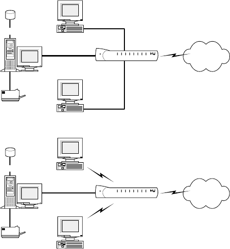
The Intel® AnyPoint® DSL Gateway 4400 is an advanced
services gateway that combines the functions of a Bridge,
Router, Switch, and DSL Modem in a single box for Internet
access and computer connectivity.
Using the gateway, you can share Internet access
seamlessly among all the computers on your network
whether you are using Ethernet or 802.11b Wireless adapters
or a combination of any of these technologies.
The Intel AnyPoint DSL Gateway 4400 connects directly to a
DSL (Digital Subscriber Line) using the built-in DSL modem.
Using the gateway and its built-in DSL modem together
enables powerful Internet access on a home or small-
business network.
Data
Server
Laser Printer
PC
PC
Gateway
Internet
Shared Drive
Data
Server
Laser Printer
PC
PC
Gateway
Internet
Shared Drive
Chapter 1 – Introduction
Copyright © 2002 Intel Corporation 3
Intel AnyPoint DSL Gateway 4400 Features
The gateway has the following features:
• Easy to install
• Automatic first time use setup wizard
• Port forwarding
• Configurable WAN MAC Address
• UPnP support
• Automatic diagnostic tests
• Readily available troubleshooting tips
• Simple Web-based user interface
• Internet sharing on your network
• Built-in firewall for network security
System Requirements
To configure the gateway, your computer must meet
certain requirements. Choose the list appropriate to your
computer’s operating system:
Windows* • 166 MHz Pentium processor, performance level or
better
• Windows* 95, 98, Me, 2000, XP, or NT*
• 32 MB of RAM, or more
• CD-ROM drive
• 800 x 600 resolution monitor (SVGA) or higher
• One of the following:
• 10/100 Ethernet or 10 baseT Ethernet adapter
• Wireless PC Card (802.11b/Wi-Fi)
• Web browser (Microsoft Internet Explorer* 5.0 or
later, Netscape Navigator* 4.75 or later, or
equivalent)
Chapter 1 – Introduction
Copyright © 2002 Intel Corporation
4
Macintosh* • PowerPC* or 680x0*
• Mac OS 7.6.1 or later
• 32 MB of RAM, or more
• 800 x 600 resolution monitor (SVGA) or higher
• One of the following:
• 10/100 Ethernet or 10 baseT Ethernet adapter
• Wireless PC Card (802.11b/Wi-Fi)
• CD-ROM drive
• Web browser (Microsoft Internet Explorer 5.0 or later;
Netscape Navigator 4.75 or later, or equivalent)
Linux • 166 MHz Pentium processor or higher
• 32MB of RAM, or more
• 800 x 600 resolution monitor (SVGA) or higher
• One of the following:
• 10/100 Ethernet or 10 baseT Ethernet adapter
• Wireless PC Card (802.11b/Wi-Fi)
• CD-ROM drive
• X-Windows* system
• Graphical Web browser (Netscape Navigator 4.75 or
later)
Service Requirements
Before you can use the gateway, you must have the
following services activated:
• Broadband account from your local telephone
company or Broadband provider
• Broadband Internet access account from your local
Broadband provider or Internet Service Provider
(ISP)
If you do not have these services set up, then contact
your local telephone company for more information.

Chapter 1 – Introduction
Copyright © 2002 Intel Corporation 5
A look at the Gateway Hardware
Front Panel The Intel Gateway’s front panel has a series of eight
lights (plus a power on indicator) that provide information
about the gateway’s operational status.
Power Normally this light is on. If it is not on, check
that the power cable connectors are securely in
place.
System Green blinking - The gateway is operating
correctly.
Yellow blinking - The gateway is operating
correctly but has detected another DHCP
server connected to one of the four Ethernet
connectors. Disconnect each Ethernet cable,
one at a time, until the system returns to green
blinking. Change the PC you've identified as a
DHCP server to a DHCP client. (See the
Troubleshooting chapter for instructions.)
If this LED is not blinking, the system is not
operating correctly. See Chapter 5 for
troubleshooting information.
AnyPoint® Gateway
Ethernet
WirelessSecurityInternetSystem
Power 1234
Chapter 1 – Introduction
Copyright © 2002 Intel Corporation
6
Internet Off - the DSL driver is not loaded.
Green blinking - the gateway is trying to
connect to the Internet.
Green solid - the gateway is connected to your
ISP but no traffic is being passed.
Amber blinking - the gateway is connected to
your ISP and traffic is being passed. This LED
blinks at a rate that corresponds to the amount
of Internet traffic (slow with little traffic and
increasingly faster as Internet traffic increases).
Security Green solid - The Firewall Settings Security
Level is set to: Normal, High, or Very High.
Red solid - The Firewall Settings Security Level
is set to: Enable Troubleshooting Mode (via the
Firewall Settings Advanced button).
Yellow blinking - A user, that is not allowed
access to your wireless network (via Advanced
> Wireless Security), is attempting to connect
to the gateway.

Chapter 1 – Introduction
Copyright © 2002 Intel Corporation 7
Back panel
connectors
The Intel Gateway’s back panel includes the cable
connectors and Reset button.
Wireless Off - There are no wireless devices
communicating with the gateway.
Green solid - at least one wireless device is
connected to the gateway.
Green blinking - traffic is being passed
between at least one wireless device and the
gateway.
Ethernet
1-4
Off - no PC is connected to any of the four
Ethernet ports.
Green solid - A valid link has been established
at 10Mbps.
Green blinking - traffic is being passed at
10Mbps.
Yellow solid - A valid link has been established
at 100Mbps.
Yellow blinking - traffic is being passed at
100Mbps.
Power Accepts the cylinder end of the power cable.
Plug the other end of the power cable into a
standard electrical outlet. (It is recommended
that you use a surge protector.) See the Power
light on the front panel in the previous section.
Ethernet Accept RJ-45 Ethernet-style connectors for
connecting up to four PCs to the gateway’s 4-
port switch.
Power
12V/1.2A
Ethernet DSL
Reset
4321
Chapter 1 – Introduction
Copyright © 2002 Intel Corporation
8
Items included with the Gateway
You should have the following items ready prior to
installation:
•Intel
AnyPoint DSL Gateway 4400
• Power Supply
• Standard phone cable
• Standard Ethernet Cable
•Intel
AnyPoint DSL Gateway 4400 CD-ROM
•Intel
AnyPoint DSL Gateway 4400 Installation Guide
The Gateway
CD-ROM
The exact contents of the CD-ROM varies by Broadband
provider. Do not assume that the CDs are
interchangeable. One provider may have different default
software configurations than another, and the
configurations are often not compatible with each other.
Only use the CD supplied to you by your provider.
Reset Use a blunt object, such as a paper clip, to
press the reset switch. You can use the reset
switch to either:
• Reset the gateway without losing its current
setup values. Press, then immediately release
the reset switch.
• Reset the gateway to its factory-default values.
Press the reset switch and hold it in the pressed
state for at least 5 seconds before releasing it.
DSL Accepts a standard phone cable connector for
attaching the gateway to your DSL (digital
subscriber line) service outlet.

Chapter 1 – Introduction
Copyright © 2002 Intel Corporation 9
All gateway CDs contain the following:
•A readme text file, with basic product information and
any known issues that were not available at the time
of the publication of this manual
• The Intel AnyPoint DSL Gateway 4400 Installation
Guide, available as a .pdf file
• The Intel AnyPoint DSL Gateway 4400 User’s Guide,
available as a .pdf file
Finding Information
Installation
Guide
The Installation Guide offers an overview of the basic
steps necessary to connect and configure your new
gateway.
User’s Guide The User’s Guide contains more detailed information on
connecting and configuring your new gateway. It is
designed for users who have less experience with
installing and configuring gateways and home networking
equipment. The User’s Guide can also be used as a
helpful reference tool.
Online Help Use the online help for more information on screen
descriptions. Troubleshooting information is also
available for the diagnostic tests.
Running the Internet Setup Wizard
Note The following describes how to access the
Internet Setup Wizard for purposes of modifying
the gateway’s configuration. If the gateway has
not yet been configured, then follow the
instructions provided in the Installation Guide.
Chapter 1 – Introduction
Copyright © 2002 Intel Corporation
10
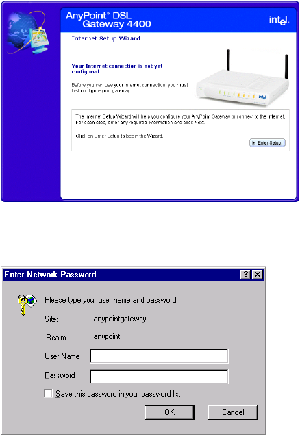
To run the Internet Setup Wizard:
1Insert the CD and wait for the Internet Setup Wizard
window to appear. (If the Autorun window does not
appear, run the program autorun.exe on the CD.)
The following screen will appear, if the gateway has
not yet been configured. If the gateway has already
been configured, a slightly different screen will
appear.
2Click the Enter Setup button.
The following appears.
3Enter admin in both the User Name and Password
fields, and then click OK.
Chapter 1 – Introduction
Copyright © 2002 Intel Corporation 11
If the gateway has not yet been configured, you will be
required to enter specific information before you can
access other features of the Setup Wizard. If the gateway
has already been configured, you can access other
features of the Internet Setup Wizard using the available
menu selections. Each feature is described in this User
Guide.
Chapter 1 – Introduction
Copyright © 2002 Intel Corporation
12

Copyright © 2002 Intel Corporation 13
Chapter 2
Configuring your DSL Settings
The Installation Guide provides step-by-step instructions
for setting up and configuring a single wired or wireless
PC connected to the gateway.
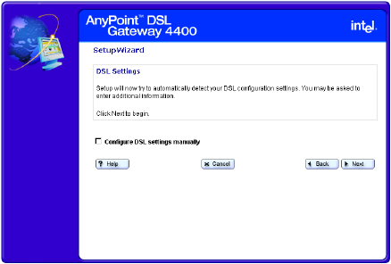
During installation, you have the option of letting setup
automatically detect your settings or setting these
manually.
If you accept the default selection, allowing the gateway
to automatically detect your settings, then you should
only need to enter minimal information, if any at all.
If you elect to set your settings manually, then you will
have to step through several screens to complete the
setup.
This chapter covers all the possible settings you may
have to enter in the following topics:
■Specifying connection information
■Specifying a connection type
■Specifying a PPP username and password
■Specifying an IP address
■Specifying a name server

Chapter 2 – Configuring your DSL Settings
Copyright © 2002 Intel Corporation
14
Specifying connection information
You specify VPI/VCI connection information using the
Connection Information screen.
Related topics •See Specifying a connection type on page 16.
•See Specifying a PPP username and password on
page 19.
•See Specifying an IP address on page 22.
•See Specifying a name server on page 25.
Step-by-step To specify your VPI/VCI connection information:
1Click the Settings menu to expand its selections.
2Click Next.
The following appears.
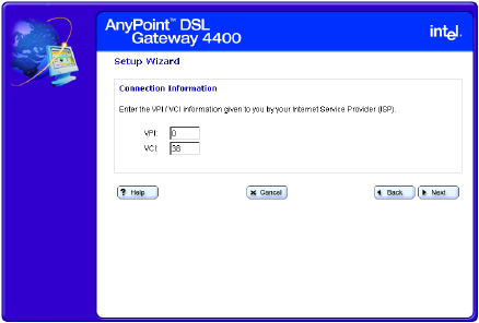
Chapter 2 – Configuring your DSL Settings
Copyright © 2002 Intel Corporation 15
3Click Configure DSL settings manually then click
Next.
The following appears.
4Enter the VPI information in the VPI field.
5Enter the VCI information in the VCI field.
6Click Next.
More about VPI
Virtual Path Identifier. This is part of the PVC. This,
combined with the VCI, establishes your “channel”
through the phone company equipment. Acceptable
values are: 0-255.
VCI
Virtual Circuit Identifier. This number is part of the PVC. It
establishes your “channel” through the telephone
company equipment. Acceptable values are: 0-65,535.

Chapter 2 – Configuring your DSL Settings
Copyright © 2002 Intel Corporation
16
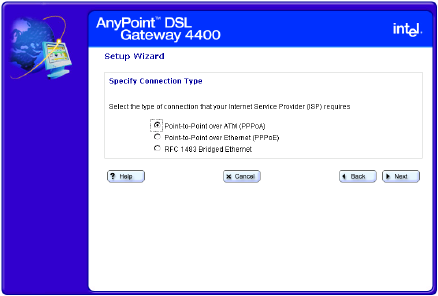
Specifying a connection type
You specify a connection type using the Specify
Connection Type screen.
Related topics •See Specifying connection information on page 14.
•See Specifying a PPP username and password on
page 19.
•See Specifying an IP address on page 22.
•See Specifying a name server on page 25.
Step-by-step To specify a connection type:
1Click the Settings menu to expand its selections.
2Click Next.
The following appears.
Chapter 2 – Configuring your DSL Settings
Copyright © 2002 Intel Corporation 17
3Click Configure DSL settings manually then click
Next until you see the following screen.
4Select one of the following connection types, as
required by your ISP, then click Next. (See More
about for more information.)
•Point-to-Point over ATM (PPPoA)
•Point-to-Point over Ethernet (PPPoE)
•RFC 1483 Bridged Ethernet option
More about PPPoA
Point-to-Point over ATM Protocol is a protocol that some
ISPs use to give users access to the ISP’s computers
and the Internet. Your ISP can tell you if you need
PPPoA, or a different protocol supported by your
gateway (Bridged Ethernet, or Point-to-Point Protocol
over Ethernet (PPPoE).
PPPoE
Point-to-Point over Ethernet Protocol is a protocol that
some ISPs use to give users access to the ISP’s
computers and the Internet. Your ISP can tell you if you
need PPPoE, or a different protocol supported by your
Chapter 2 – Configuring your DSL Settings
Copyright © 2002 Intel Corporation
18
gateway (Bridged Ethernet, or Point-to-Point over ATM
Protocol (PPPoA).
RFC1483
A standard that provides guidelines for Bridged Ethernet
and Routed Ethernet connection protocols. Your ISP can
tell you if you will use one of the RFC1483 protocols, or a
different protocol supported by your gateway (PPPoA,
PPPoE).

Chapter 2 – Configuring your DSL Settings
Copyright © 2002 Intel Corporation 19
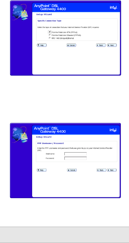
Specifying a PPP username and password
You specify a PPP username and password using the
PPP Username/Password screen.
Related topics •See Specifying connection information on page 14.
•See Specifying a connection type on page 16.
•See Specifying an IP address on page 22.
•See Specifying a name server on page 25.
Step-by-step To specify a PPP username and password:
1Click the Settings menu to expand its selections.
2Click Next.
The following appears.
Chapter 2 – Configuring your DSL Settings
Copyright © 2002 Intel Corporation
20
3Click Configure DSL settings manually then click
Next until you see the following screen.
4On the “Connection Type” screen, click either Point-
to-Point over ATM (PPPoA) or Point-to-Point over
Ethernet (PPPoE).
5Click Next .
The following appears.
6Enter a PPP username and password in the User
Name and Password fields provided.
Important! Your username and password are case
sensitive.
Chapter 2 – Configuring your DSL Settings
Copyright © 2002 Intel Corporation 21
Chapter 2 – Configuring your DSL Settings
Copyright © 2002 Intel Corporation
22
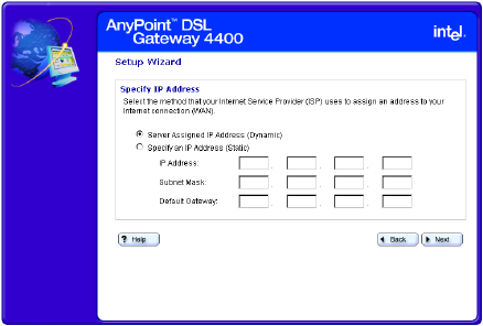
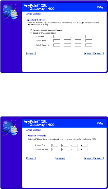
Specifying an IP address
You specify an IP address using the Specify IP Address
screen.
Related topics •See Specifying connection information on page 14.
•See Specifying a connection type on page 16.
•See Specifying a PPP username and password on
page 19.
•See Specifying a name server on page 25.
Step-by-step To specify an IP address:
1Click the Settings menu to expand its selections.
2Click Next.
The following appears.
Chapter 2 – Configuring your DSL Settings
Copyright © 2002 Intel Corporation 23
3Click Configure DSL settings manually then click
Next until you see the following screen.
4Select one of the following methods your ISP uses to
assign an address to your Internet connection.
•Server assigned IP address (dynamic) –
Select this option if your ISP assigns addresses
dynamically.
•Specify an IP address (static) – Select this
option if your ISP assigns addresses statically. If
you select this option then you must enter the IP
Address, Subnet Mask, and Default Gateway
information in the fields provided.
More about Each computer or networked device on the Internet is
identified by a unique IP address. Your gateway must be
identified by the correct address in order for you to
access the Internet.
Your ISP uses one of two methods to assign an IP
address to you:
•Dynamic (also called server-assigned, automatic, or
DHCP). If your ISP assigns IP addresses
dynamically, your gateway receives an IP address
from a pool of IP addresses when you connect to
Chapter 2 – Configuring your DSL Settings
Copyright © 2002 Intel Corporation
24
your ISP. Your ISP “owns” the IP addresses in the
pool.
•Static (also called permanent). If your ISP assigns
static IP addresses, your provider selects an address
from an assigned pool and assigns it to you
permanently. This number is provided on the setup
information page given to you by your ISP.

Chapter 2 – Configuring your DSL Settings
Copyright © 2002 Intel Corporation 25
Specifying a name server
You specify a name server using the Specify a Name
Server screen.
Related topics •See Specifying connection information on page 14.
•See Specifying a connection type on page 16.
•See Specifying a PPP username and password on
page 19.
•See Specifying an IP address on page 22.
Step-by-step To specify a name server:
1Click the Settings menu to expand its selections.
2Click Next.
The following appears.
Chapter 2 – Configuring your DSL Settings
Copyright © 2002 Intel Corporation
26
3Click Configure DSL settings manually then click
Next until you see the following screen.
4Select the Specify an IP Address (Static) option,
enter the IP Address, Subnet Mask, and Default
Gateway information in the fields provided, then click
Next.
The following appears.
5Enter the Primary DNS (and optionally, secondary) IP
provided by your ISP.
More about A name server DNS IP address is the IP address of the
computer that your ISP uses to translate between
numeric IP addresses and human-readable addresses.
Chapter 2 – Configuring your DSL Settings
Copyright © 2002 Intel Corporation 27
For example, 192.168.0.254 is a numeric IP address and
www.intel.com is a human-readable address.
Chapter 2 – Configuring your DSL Settings
Copyright © 2002 Intel Corporation
28

Copyright © 2002 Intel Corporation 29
Chapter 3
Setting up the Gateway with a Network
This chapter explains how to connect additional
computers to your wired or wireless network.
■Connecting the gateway to an Ethernet hub or switch
■Connecting the gateway to a wireless network
■Using the Wireless Network Configuration Wizard
■Configuring the gateway’s firewall
■Using port forwarding
Note Do not attempt to connect multiple computers to
form a network until you have configured the
gateway to work with a single computer, as
described in the Installation Guide.

Chapter 3 – Setting up the Gateway with a Network
Copyright © 2002 Intel Corporation
30
Connecting the gateway to an Ethernet hub or switch
Once you have established a connection between the
gateway and a single computer with an Ethernet adapter,
you can then connect additional computers to the wired
network.
Related topics •See Connecting the gateway to a wireless network
on page 32.
•See Using the Wireless Network Configuration
Wizard on page 35.
•See Configuring the gateway’s firewall on page 51.
•See Using port forwarding on page 59.
Note Do not attempt to connect multiple computers to
form a network until you have configured the
gateway to work with a single computer. Refer to
your Installation Guide for instructions on
configuring the gateway to do this.
Chapter 3 – Setting up the Gateway with a Network
Copyright © 2002 Intel Corporation 31
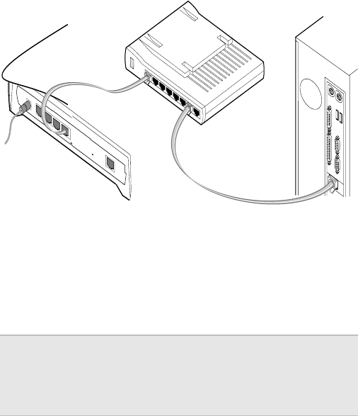
Step-by-step To connect the gateway to a hub or switch:
1Connect one end of the Ethernet cable (included with
the gateway) to any one of the four Ethernet ports on
the gateway.
2Connect the other end to the Ethernet cable to an
available port on your hub or switch.
3Connect the power cable to the power supply.
4Connect the power cable to an electrical wall outlet.
5Connect the power supply cable to the Power port on
the gateway.
Note If you are using the gateway as a DHCP server,
make sure the computers on your network are
configured to be DHCP clients. Refer to Chapter
5 for information.
Power Ethernet DSL
Reset
12V/1.2A

Chapter 3 – Setting up the Gateway with a Network
Copyright © 2002 Intel Corporation
32
Connecting the gateway to a wireless network
Once you have established a connection between the
gateway and a single computer with an 802.11b wireless
adapter, you can then connect additional computers to
the wireless network.
Related topics •See Connecting the gateway to an Ethernet hub or
switch on page 30.
•See Using the Wireless Network Configuration
Wizard on page 35.
•See Configuring the gateway’s firewall on page 51.
•See Using port forwarding on page 59.
Step-by-step To connect the gateway to a wireless network:
• refer to the Intel® AnyPoint® Wireless II Installation
Guide for instructions on installing the remaining
computers with wireless adapters on your network. (If
you have purchased a non-Intel 802.11b wireless
adapter, refer to the instructions provided with your
adapter.)
• Set the Network Name (SSID) and Encryption to be
the same for the gateway and each wireless adapter.
To set the Network Name and Encryption for your
wireless adapters, refer to the instructions provided
with them.
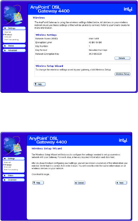
To set the Network Name and Encryption for the
gateway:
1Click the Settings menu to expand its selections.
Note Do not attempt to connect multiple computers to
form a network until you have configured the
gateway to work with a single computer. Refer to
your Installation Guide for instructions on
configuring the gateway to do this.
Chapter 3 – Setting up the Gateway with a Network
Copyright © 2002 Intel Corporation 33
2Click Wireless to view your current wireless settings.
The following appears.
3Click the Wireless Setup button to enter the
Wireless Setup Wizard.
The following appears.
4Click Next, then enter the Network Name.

Chapter 3 – Setting up the Gateway with a Network
Copyright © 2002 Intel Corporation
34
5Click Next, then select an encryption option.
Each of these steps is described in more detail on
subsequent pages.
Note If you change the Network Name (SSID) or the
Encryption Password and forget the values, you
must reset the gateway to the factory default
settings. The reset button is located on the back
of the gateway and is not labeled. This button is
recessed. Use a paper clip to depress the button
for at least 5 seconds. You may then reconfigure
the gateway with the settings given to you by
your ISP, and the 802.11b wireless adapters
with the default gateway settings.
Chapter 3 – Setting up the Gateway with a Network
Copyright © 2002 Intel Corporation 35
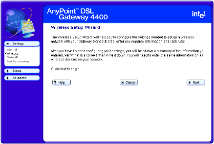
Using the Wireless Network Configuration Wizard
The Wireless Network Wizard guides you through the
steps necessary to configure a wireless network with
your Gateway.
Related topics •See Specifying a wireless network name (SSID) on
page 37.
•See Correcting for wireless interference on page 39.
•See Changing or disabling encryption settings on
page 42.
•See Specifying a wireless encryption key from text on
page 44.
•See Entering a key manually on page 46.
•See Disabling wireless encryption on page 49.
Step-by-step To use the Wireless Wizard:
1Click the Settings menu to expand its selections.
2Click Wireless to view your current wireless settings,
then click the Wireless Setup button to enter the
Wireless Setup Wizard.
The following appears.
3For each step, enter any required information then
click Next.
Chapter 3 – Setting up the Gateway with a Network
Copyright © 2002 Intel Corporation
36
4Click Help on any screen for more information.
5Click Back on any screen to move back to the
previous window.
6Click Next on any screen to move forward to the next
window.
7Click Cancel on any screen to exit the Wireless
Wizard, without applying changes.
More about To communicate with each other, all wireless devices on
the same network must use the same Network Name
(SSID) and Encryption Password (if encryption is
enabled). In the next several screens you will enter the
Network Name and specify encryption.
Chapter 3 – Setting up the Gateway with a Network
Copyright © 2002 Intel Corporation 37
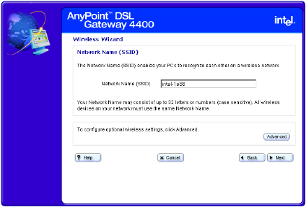
Specifying a wireless network name (SSID)
You specify a network name (SSID) using the Wireless
Settings – Network Name screen.
Related topics •See Correcting for wireless interference on page 39.
•See Changing or disabling encryption settings on
page 42.
•See Specifying a wireless encryption key from text on
page 44.
•See Entering a key manually on page 46.
•See Disabling wireless encryption on page 49.
Step-by-step To specify a network name (SSID):
1Click the Settings menu to expand its selections.
2Click Wireless to view your current wireless settings,
then click the Wireless Setup button to enter the
Wireless Setup Wizard.
3Click Next until you see the “Network Name” screen.
The following appears.
4Enter a string of up to 32 letters or numbers (case
sensitive) in the Network Name (SSID) field. (See

Chapter 3 – Setting up the Gateway with a Network
Copyright © 2002 Intel Corporation
38
“Default Network Name,” below, for more
information.)
5Click Next.
Default
Network Name
The factory default value for the Network Name, unique
for each gateway, is located on the bottom of the
gateway and is originally displayed in the Network Name
(SSID) field. You may want to change this value from the
default setting to something you can easily remember.
More about To communicate with each other, all wireless devices on
the same network must use the same Network Name
(SSID) and Encryption Password (if encryption is
enabled). In this screen you enter the Network Name. On
a subsequent screen you will specify an Encryption
Password.
Note Network Name is also referred to as SSID,
ESSID, BSSID, or network code.
Chapter 3 – Setting up the Gateway with a Network
Copyright © 2002 Intel Corporation 39
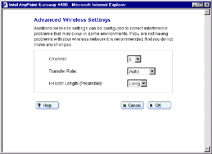
Correcting for wireless interference
If you are experiencing wireless interference you can
correct for it using the Advanced Wireless Settings,
accessible from the Wireless Settings – Network Name
screen.
Related topics •See Specifying a wireless network name (SSID) on
page 37.
•See Changing or disabling encryption settings on
page 42.
•See Specifying a wireless encryption key from text on
page 44.
•See Entering a key manually on page 46.
•See Disabling wireless encryption on page 49.
Step-by-step To correct for interference with your wireless connection:
1Click the Settings menu to expand its selections.
2Click Wireless to view your current wireless settings,
then click the Wireless Setup button to enter the
Wireless Setup Wizard.
3Click Next until you see the “Network Name” screen.
Chapter 3 – Setting up the Gateway with a Network
Copyright © 2002 Intel Corporation
40
4Click Advanced.
The following appears.
5Select an alternate channel using the Channel list
box.
6Select an alternate transfer rate using the Transfer
Rate box.
More about
Channel In areas where many networks are using the same
channel, throughput on all the networks may decline.
In addition, if there is interference on the channel,
signal quality is affected. If the performance of your
network declines, try selecting another channel. It is
recommended that you try channels 6 and 11 first as
alternative channels. The default channel is 6.
Chapter 3 – Setting up the Gateway with a Network
Copyright © 2002 Intel Corporation 41
Transfer Rate By default, the transfer rate between wireless
devices is automatically determined. Generally, you
will not need to change this value. However,
decreasing the transfer rate may enable you to
transmit across greater distances.
Header Length (Preamble) The Header length is the format for labeling the
information sent between devices. The only available
setting is Long. The short header length is not
supported because not all wireless devices support
this feature. You must set all your other wireless
devices, to which the gateway is connected, to Long
(typically the default setting).
Chapter 3 – Setting up the Gateway with a Network
Copyright © 2002 Intel Corporation
42
Changing or disabling encryption settings
In a Wireless Local Area Network (WLAN), you can use
encryption to implement security and protect your
information. The default encryption setting is 40/64-bit
hexadecimal. Network encryption does not provide
absolute protection for your data, but it does make it
more difficult for someone else to intercept that data. It is
recommended that you utilize the encryption feature of
this product.
Related topics •See Specifying a wireless network name (SSID) on
page 37.
•See Correcting for wireless interference on page 39.
•See Specifying a wireless encryption key from text on
page 44.
•See Entering a key manually on page 46.
•See Disabling wireless encryption on page 49.
Step-by-step To change or disable encryption:
1Click the Settings menu to expand its selections.
2Click Wireless to view your current wireless settings,
then click the Wireless Setup button to enter the
Wireless Setup Wizard.
Chapter 3 – Setting up the Gateway with a Network
Copyright © 2002 Intel Corporation 43
3Click Next until you see the “Encryption” screen.
(Your encryption screen may contain different
information, depending on how encryption was last set.
See the following encryption topics for more information.
4Select an encryption option then enter the required
information in the fields associated with that
selection. See the following topics for more
information.
More about The longer the encryption key is, the stronger the
encryption. The gateway uses either a 40(64)-bit key or a
104(128)-bit key. A 104(128)-bit key has several trillion
times more combinations than a 40(64)-bit key. For
added security, you should change your encryption key
often.
Important! The gateway and each adapter in the
network must have the same encryption
keys.
Chapter 3 – Setting up the Gateway with a Network
Copyright © 2002 Intel Corporation
44
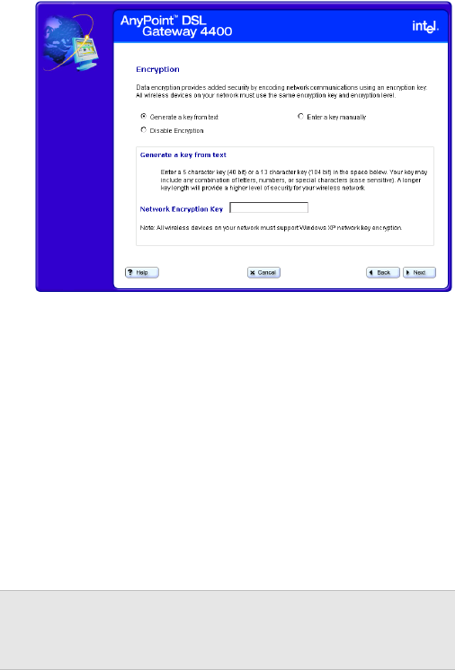
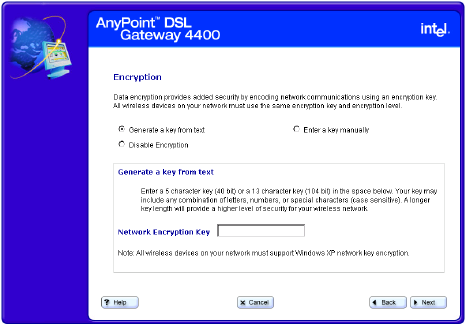
Specifying a wireless encryption key from text
If you have all Intel® AnyPoint® adapters, you can create
an encryption key from a 5 or 13 character string. A 5
character string provides 40-bit encryption, while a 13
character string provides 104-bit encryption. The string
you enter must be exactly 5 or 13 characters.
Related topics •See Specifying a wireless network name (SSID) on
page 37.
•See Correcting for wireless interference on page 39.
•See Changing or disabling encryption settings on
page 42.
•See Entering a key manually on page 46.
•See Disabling wireless encryption on page 49.
Step-by-step To specify a wireless encryption key from text:
1Click the Settings menu to expand its selections.
2Click Wireless to view your current wireless settings,
then click the Wireless Setup button to enter the
Wireless Setup Wizard.
3Click Next until you see the “Encryption” screen.
Chapter 3 – Setting up the Gateway with a Network
Copyright © 2002 Intel Corporation 45
4Click the Generate a key from text option.
The following appears.
5Enter a 5-character (40-bit) or a 13-character (104-
bit) string, in any combination of letters, numbers, or
special characters (case sensitive) in the Network
Encryption Key field.
Chapter 3 – Setting up the Gateway with a Network
Copyright © 2002 Intel Corporation
46
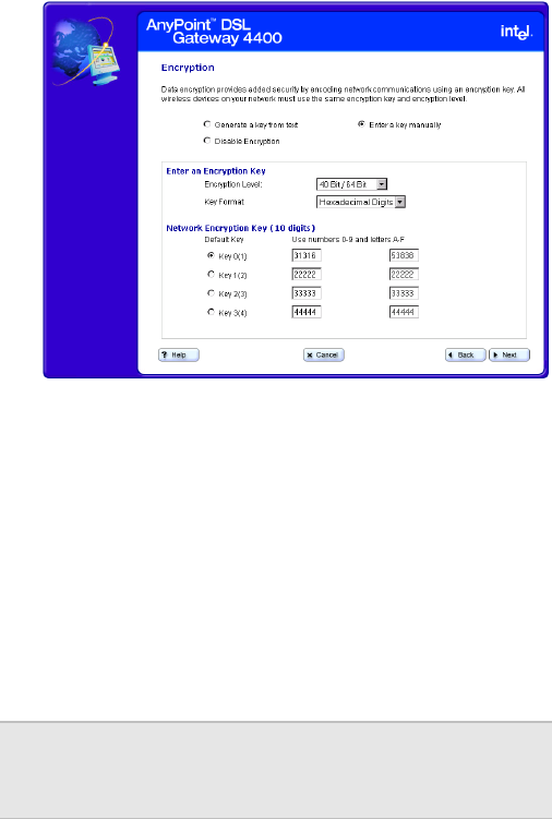
Entering a key manually
If you are not using Intel® AnyPoint® network adapters
you can manually enter a key, either as a series of 40/64
bit or 104/128-bit hexadecimal digits (characters 0
through 9 and A through E) or as 40/64 bit or 104/128-bit
ASCII characters (any character).
Related topics •See Specifying a wireless network name (SSID) on
page 37.
•See Correcting for wireless interference on page 39.
•See Changing or disabling encryption settings on
page 42.
•See Specifying a wireless encryption key from text on
page 44.
•See Disabling wireless encryption on page 49.
Step-by-step To enter a key manually:
1Click the Settings menu to expand its selections.
2Click Wireless to view your current wireless settings,
then click the Wireless Setup button to enter the
Wireless Setup Wizard.
3Click Next until you see the “Encryption” screen.
Chapter 3 – Setting up the Gateway with a Network
Copyright © 2002 Intel Corporation 47
4Click the Enter a key manually option.
Your screen will look similar to the following.
5Select either Hexadecimal digits or ASCII
Characters from the Key Format list box.
6Select either 40 Bit/64 Bit or 104 Bit/128 Bit from
the Encryption Level list box.
7Click a Key option, then enter a unique 10
hexadecimal digit (2 pairs of 5-digits) string in its
associated field. The four Key options allow you to
specify four different keys that you can select at any
time.
More about A 40/64-bit key can consist of 10 hexadecimal digits or 5
ASCII characters:
• Example Hex Key: 1AC78 24DE5
• Example ASCII Key: JimBo
Note You can only use one encryption key at a time.
Having four sets of keys allows you to quickly
change your encryption, if necessary.
Chapter 3 – Setting up the Gateway with a Network
Copyright © 2002 Intel Corporation
48
A 104/128-bit key can consist of 26 hexadecimal digits or
13 ASCII characters.
• Example Hex Key: 10111 2EF14 1510 2453 6543
9991
• Example ASCII Key: IntelWireless
Chapter 3 – Setting up the Gateway with a Network
Copyright © 2002 Intel Corporation 49
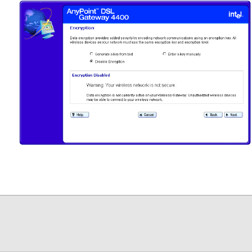
Disabling wireless encryption
You can disable encryption if you are not worried about
security and want to slightly improve data transmission.
Related topics •See Specifying a wireless network name (SSID) on
page 37.
•See Correcting for wireless interference on page 39.
•See Changing or disabling encryption settings on
page 42.
•See Specifying a wireless encryption key from text on
page 44.
•See Entering a key manually on page 46.
Step-by-step To disable the encryption settings:
1Click the Settings menu to expand its selections.
2Click Wireless to view your current wireless settings,
then click the Wireless Setup button to enter the
Wireless Setup Wizard.
3Click Next until you see the “Encryption” screen.
Chapter 3 – Setting up the Gateway with a Network
Copyright © 2002 Intel Corporation
50
4Click the Disable Encryption option.
The following appears.
5Click Next to apply the change.
More about In a Wireless Local Area Network (WLAN), you can use
encryption to implement security and protect your
information. The default encryption setting is 40/64-bit
hexadecimal. Network encryption does not provide
absolute protection for your data, but it does make it
more difficult for someone else to intercept that data. It is
recommended that you utilize the encryption feature of
this product.
Important! Be sure to also disable encryption for
each adapter in your wireless network.
Refer to the documentation for you
wireless adapter.
Chapter 3 – Setting up the Gateway with a Network
Copyright © 2002 Intel Corporation 51
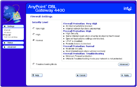
Configuring the gateway’s firewall
The gateway includes a built-in firewall set to a Normal
security level, by default. A “Normal” security level means
that internal processes or modules such as the Universal
Plug and Play Internet Gateway Device (UPnP IGD) have
permission to dynamically auto-configure port-forward
rules in their respective domains to provide ease of use.
It also means that HTTP UI smart port-forwarding is
enabled. As a result, Internet applications that require
user configured port-forwarding rules are available.
Related topics •See Specifying the firewall security level on page 53.
•See Specifying intrusion detection settings on page
55.
•See Specifying IP addresses to be excluded from
being blocked on page 57.
Step-by-step To configure the gateway’s firewall:
1Click the Settings menu to expand its selections.
2Click Firewall.
The following appears.
3Select a security level from the main screen, specify
intrusion detection settings or specify IP addresses to
Chapter 3 – Setting up the Gateway with a Network
Copyright © 2002 Intel Corporation
52
be excluded from the firewall detection system from
the Advanced screen. You can also allow your
service provider to troubleshoot your network directly
by clicking the Troubleshooting mode option.
More about Specific details about each of the firewall settings are
described in the next several topics.
Chapter 3 – Setting up the Gateway with a Network
Copyright © 2002 Intel Corporation 53
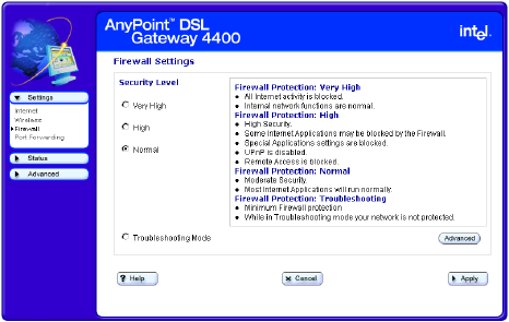
Specifying the firewall security level
You specify the firewall security level using the Firewall
Settings main screen.
Related topics •See Specifying intrusion detection settings on page
55.
•See Specifying IP addresses to be excluded from
being blocked on page 57.
Step-by-step To specify the firewall security level:
1Click the Settings menu to expand its selections.
2Click Firewall.
The following appears.
3Select one of the following options (see More About
for more information about the options):
•Very High
•High
•Normal (default)
4Select Troubleshooting Mode to allow your service
provider to troubleshoot your network by accessing it
directly.
Chapter 3 – Setting up the Gateway with a Network
Copyright © 2002 Intel Corporation
54
5[Optional] Click Advanced to specify intrusion
detection settings and/or to exclude specific IP
addresses from the firewall intrusion detection
system.
6Click Apply to save these new settings.
More about Following describes the three levels of firewall protection
available for the gateway:
•Very High – all incoming/outgoing traffic over the
WAN interface is blocked and the home network is
isolated from the Internet.
•High – all user configured port-forwarding rules are
disabled. No user or application can remove port-
forwarding rules. HTTP UI smart port-forwarding is
disabled. As a result, Internet applications that
require user configured port-forwarding rules will not
be available.
This mode is appropriate for home users who just
want to access the Internet from their client PCs and
do not plan to run any special server software in their
home network.
•Normal (default) – Internal processes or modules
such as the Universal Plug and Play Internet
Gateway Device (UPnP IGD) have permission to
dynamically auto-configure port-forward rules in their
respective domains to provide ease of use. HTTP UI
smart port-forwarding is enabled. As a result, Internet
applications that require user configured port-
forwarding rules are available.
Chapter 3 – Setting up the Gateway with a Network
Copyright © 2002 Intel Corporation 55
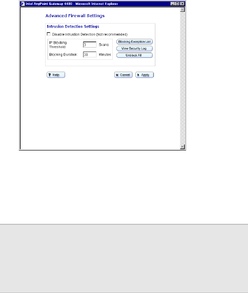
Specifying intrusion detection settings
You specify intrusion detection settings using the firewall
security settings Advanced screen.
Related topics •See Specifying the firewall security level on page 53.
•See Specifying IP addresses to be excluded from
being blocked on page 57.
Step-by-step To specify intrusion detection settings:
1Click the Settings menu to expand its selections.
2Click Firewall.
3Click Advanced.
The following appears.
4Do any of the following:
•Disable Intrusion Detection (Not
recommended) – Click this checkbox to disable
the firewall intrusion detection system.
Important! Disabling the intrusion detection system
opens your network to unsolicited Internet
traffic, thus making your network
susceptible to intrusion attacks, viruses,
and so on.
Chapter 3 – Setting up the Gateway with a Network
Copyright © 2002 Intel Corporation
56
•Set IP Blocking Threshold – Enter a number in
this text field. See More About for more
information.
•Set Blocking Duration – Enter a number in this
text field. See More About for more information.
•Blocking Exception List – Click this button to
access another screen in which you can specify
IP addresses to be excluded from being blocked.
•View the Security Log – Click this button to
view the Security Log.
•Unblock All – Click this button to exclude all IP
addresses from being blocked.
5Click Apply to save these new settings.
More about Following describes the IP Blocking Threshold and
Blocking Duration in more detail.
•Set IP Blocking Threshold – This sets the
maximum number of port scans that can occur by an
external IP address before that IP address is
blocked. Enter a number in this text field. The default
value is 3. Recommended range is 2-5.
•Set Blocking Duration – This sets the minimum
duration during which a detected intruding IP address
cannot access your network. Enter a number in this
text field. The default value is 30 (minutes).
Recommended blocking duration should not exceed
one day.
Chapter 3 – Setting up the Gateway with a Network
Copyright © 2002 Intel Corporation 57
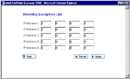
Specifying IP addresses to be excluded from being blocked
You specify IP addresses to be excluded from being
blocked by the firewall intrusion detection system using
the firewall security settings Advanced screen.
Related topics •See Specifying the firewall security level on page 53.
•See Specifying intrusion detection settings on page
55.
Step-by-step To specify IP addresses to be excluded from being
blocked:
1Click the Settings menu to expand its selection.
2Click Firewall.
3From the Firewall Settings screen, click Advanced.
4From the Intrusion Detection Settings screen, click
Blocking Exception List.
The following appears.

Chapter 3 – Setting up the Gateway with a Network
Copyright © 2002 Intel Corporation
58
5Enter each IP address to be blocked in the fields
provided.
6Click Apply to apply these settings.
Important! Allowing an external IP address complete
access to your network opens your
network to unsolicited Internet traffic from
that IP address, thus making your
network susceptible to intrusion attacks,
viruses, and so on.

Chapter 3 – Setting up the Gateway with a Network
Copyright © 2002 Intel Corporation 59
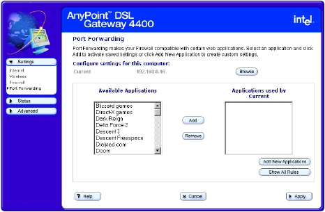
Using port forwarding
Port forwarding is useful if you have a web server running
on a computer on your local network. It allows you to
automatically direct traffic to a specific computer on your
network. You may also need port forwarding to host
some multi-player games, for video phone applications,
and for other interactive applications.
Related topics •See Enabling port forwarding on page 61.
•See Selecting a target computer by name on page
63.
•See Selecting a target computer by IP address on
page 65.
•See Creating a custom rule on page 67.
Step-by-step To enable port forwarding:
1Click the Settings menu to expand its selections.
2Click Port Forwarding.
The following appears.
Chapter 3 – Setting up the Gateway with a Network
Copyright © 2002 Intel Corporation
60
You can use this screen to:
• specify the computer on your network to which the
inbound traffic is to be directed.
• specify the service (or application) the inbound traffic
is intended for – for instance, POP3, FTP, HTTP, and
so on.
• Create a custom rule that defines a specific port and
protocol for unsolicited inbound traffic.
More about Specific details about using port forwarding are described
in the next several topics.
Chapter 3 – Setting up the Gateway with a Network
Copyright © 2002 Intel Corporation 61
Enabling port forwarding
You configure your port forwarding requirement using the
Port Forwarding screen.
• specify the computer on your network to which the
inbound traffic is to be directed.
• specify the service (or application) the inbound traffic
is intended for – for instance, POP3, FTP, HTTP, and
so on.
• Create a custom rule that defines a specific port and
protocol for unsolicited inbound traffic.
Related topics •See Selecting a target computer by name on page
63.
•See Selecting a target computer by IP address on
page 65.
•See Creating a custom rule on page 67.
Step-by-step To enable port forwarding:
1Click the Settings menu to expand its selections.
2Click Port Forwarding.
The following appears.

Chapter 3 – Setting up the Gateway with a Network
Copyright © 2002 Intel Corporation
62
3[Optional] Click Add New Applications to create a
custom rule.
4Click Browse to specify the computer on your
network to which the inbound traffic is to be directed.
(You can then select from a list of available
computers or enter an IP address manually.)
5Click Add to select a service (or application) the
inbound traffic is intended for on the target computer.
6[Optional] Click Show All Rules to see a summary of
how ports are being forwarded to the computers on
your network.
7Click Apply to apply your changes.
More about Your gateway supports up to 20 ports or ranges of ports.
Port forwarding only applies to unsolicited inbound traffic.
If you enter an address to access a web page on the
Internet, the Web page is displayed on your browser.
This is known as solicited traffic.
Depending on the application or game that requires port
forwarding, you may find configuration information in its
documentation or on the Web.
Note If you don’t use port forwarding, then all
unsolicited inbound traffic is blocked by the
gateway’s internal firewall.
Chapter 3 – Setting up the Gateway with a Network
Copyright © 2002 Intel Corporation 63
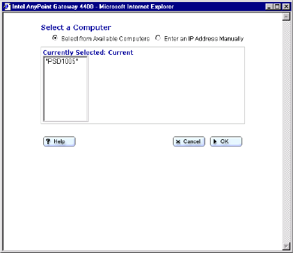
Selecting a target computer by name
You can select a target computer by name on your
network to which inbound traffic is to be directed using
the Select a Computer screen, accessible from the main
Port Forwarding screen.
Related topics •See Enabling port forwarding on page 61.
•See Selecting a target computer by IP address on
page 65.
•See Creating a custom rule on page 67.
Step-by-step To select a target computer by name:
1Click the Settings menu to expand its selections.
2Click Port Forwarding.
3From the Port Forwarding screen, click Browse.
4Click Select from available computers.
The following appears.
5Select a target computer from the list.
6Click OK.
Chapter 3 – Setting up the Gateway with a Network
Copyright © 2002 Intel Corporation
64
More about The Select from available computers option is selected
by default (the assumption is that your network assigns
IP addresses via DHCP). If you need to target a
computer that is not listed, and you know its IP address,
then select the Enter an IP address manually option
and read its online Help for more information.
Chapter 3 – Setting up the Gateway with a Network
Copyright © 2002 Intel Corporation 65
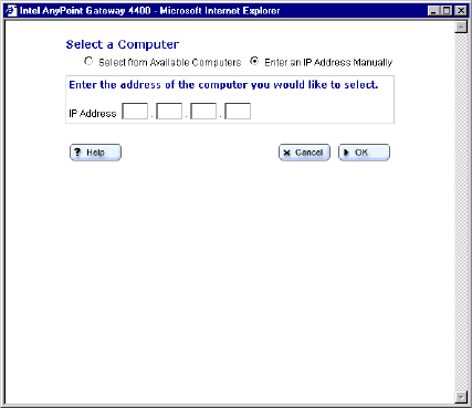
Selecting a target computer by IP address
You can select a target computer by IP address on your
network to which inbound traffic is to be directed using
the Select a Computer screen, accessible from the main
Port Forwarding screen.
Related topics •See Enabling port forwarding on page 61.
•See Selecting a target computer by name on page
63.
•See Creating a custom rule on page 67.
Step-by-step To select a target computer by IP address:
1Click the Settings menu to expand its selections.
2Click Port Forwarding.
3From the Port Forwarding screen, click Browse.
4Click Enter an IP address manually.
The following appears.
5Enter the IP address of the target computer in the IP
Address field.
6Click OK.
Chapter 3 – Setting up the Gateway with a Network
Copyright © 2002 Intel Corporation
66
More about The Select from available computers option is selected
by default (the assumption is that your network assigns
IP addresses via DHCP). Use the Enter an IP address
manually option, instead, if you need to target a
computer that is not listed, and you know its IP address.
Chapter 3 – Setting up the Gateway with a Network
Copyright © 2002 Intel Corporation 67
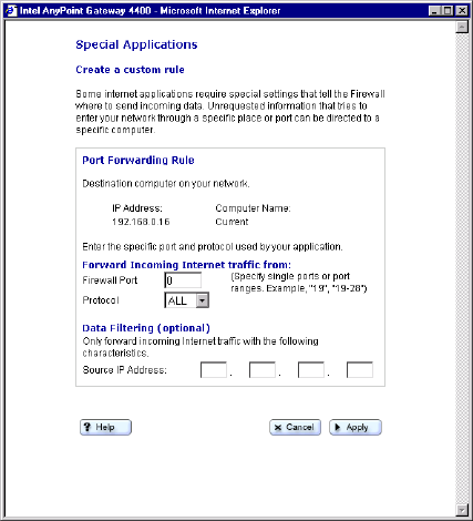
Creating a custom rule
You can create a custom rule that defines a specific port
and protocol for unsolicited inbound traffic using the Add
New Application screen, accessible from the main Port
Forwarding screen.
Related topics •See Enabling port forwarding on page 61.
•See Selecting a target computer by name on page
63.
•See Selecting a target computer by IP address on
page 65.
Step-by-step To create a custom rule:
1Click the Settings menu to expand its selections.
2Click Port Forwarding.
Chapter 3 – Setting up the Gateway with a Network
Copyright © 2002 Intel Corporation
68
3From the Port Forwarding screen, click Add New
Application.
The following appears.
4Enter a port number or range of ports in the Firewall
Port field.
5Select a transport layer protocol from the Protocol
list box.
6[Optional] For increased security purposes, enter a
Source IP Address to restrict incoming data from a
specific computer.
More about Ports can be forwarded individually or as a range
separated by a dash (for example, 23 or 24-1023).
The port numbers can be entered in the table in any
order.
A range may be specified and then individual numbers
within that range may be directed to a different IP
address. For example, you may enter a range of 1-1024
Chapter 3 – Setting up the Gateway with a Network
Copyright © 2002 Intel Corporation 69
in the Port field and an IP address of 192.168.0.251. You
may then designate Ports 23, 80, and 53 to IP address
192.168.0.252. Traffic destined for Ports 23, 80, and 53
only go to IP address 192.168.0.252.
Chapter 3 – Setting up the Gateway with a Network
Copyright © 2002 Intel Corporation
70

Copyright © 2002 Intel Corporation 71
Chapter 4
Using Advanced Configuration Options
This chapter describes the gateway’s advanced feature
set. It provides instructions for changing advanced
wireless settings, changing the gateway password,
resetting the gateway or reloading default settings,
enabling remote access, enabling Universal Plug and
Play, and so on.
■Accessing advanced configuration options
■Changing the gateway password
■Specifying wireless security settings
■Resetting the gateway or reloading default settings
■Exposing a computer outside the firewall
■Enabling remote access
■Specifying the Host and Domain names
■Specifying LAN and DHCP settings
■Disabling Universal Plug and Play (UPnP)
Chapter 4 – Using Advanced Configuration Options
Copyright © 2002 Intel Corporation
72
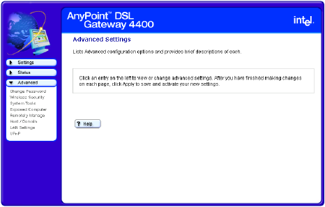
Accessing advanced configuration options
You use the Advanced Features to specify such things as
wireless security settings, LAN and DHCP settings, and
additional features as listed below.
Related topics •See Changing the gateway password on page 74.
•See Specifying wireless security settings on page 76.
•See Resetting the gateway or reloading default
settings on page 79.
•See Exposing a computer outside the firewall on
page 81.
•See Enabling remote access on page 83.
•See Specifying the Host and Domain names on page
85.
•See Specifying LAN and DHCP settings on page 87.
•See Disabling Universal Plug and Play (UPnP) on
page 90.
Step-by-step To use the advanced features:
1Click the Advanced menu to expand its selections.
The following appears.
Chapter 4 – Using Advanced Configuration Options
Copyright © 2002 Intel Corporation 73
2Select an Advanced menu option.
3Make the change on the Advanced feature screen
then click Apply.
More about Read the help pages associated with each Advanced
Settings screen for more information.
Chapter 4 – Using Advanced Configuration Options
Copyright © 2002 Intel Corporation
74
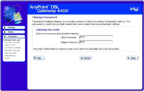
Changing the gateway password
The gateway is password protected to prevent network
users from gaining access and changing settings.
Related topics •See Accessing advanced configuration options on
page 72.
•See Specifying wireless security settings on page 76.
•See Resetting the gateway or reloading default
settings on page 79.
•See Exposing a computer outside the firewall on
page 81.
•See Enabling remote access on page 83.
•See Specifying the Host and Domain names on page
85.
•See Specifying LAN and DHCP settings on page 87.
•See Disabling Universal Plug and Play (UPnP) on
page 90.
Step-by-step To change the gateway password:
1Click the Advanced menu to expand its selections.
2Click Change Password.
The following appears.
Chapter 4 – Using Advanced Configuration Options
Copyright © 2002 Intel Corporation 75
3Type your new password, then retype it to verify.
4Click Apply to save your settings.
More about Use the following rules when creating a password.
• Five characters minimum
• At least two non-alpha characters
• No more than three identical characters
• The password should not appear in a dictionary
Chapter 4 – Using Advanced Configuration Options
Copyright © 2002 Intel Corporation
76
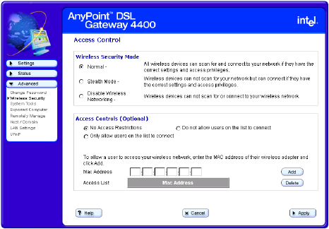
Specifying wireless security settings
You can specify scanning access to your wireless
network and create a list of users that allows or prevents
access to your network.
Related topics •See Accessing advanced configuration options on
page 72.
•See Changing the gateway password on page 74.
•See Resetting the gateway or reloading default
settings on page 79.
•See Exposing a computer outside the firewall on
page 81.
•See Enabling remote access on page 83.
•See Specifying the Host and Domain names on page
85.
•See Specifying LAN and DHCP settings on page 87.
•See Disabling Universal Plug and Play (UPnP) on
page 90.
Chapter 4 – Using Advanced Configuration Options
Copyright © 2002 Intel Corporation 77
Step-by-step To specify wireless security settings:
1Click the Advanced menu to expand its selections.
2Click Wireless Security.
The following appears.
3Use the Access Control fields, Add, and Delete
buttons to create a list of users you wish to either
provide access to or prevent access from your
wireless network. (You can only create one list that
you will then specify as “provide access to” or “do not
allow access to” your wireless network, using one of
two option buttons.)
4In the same Access Control List section of the
screen, select one of the following:
•No access restrictions – Click this to allow
unrestricted access to your wireless network.
•Only allow users on the list to connect – Click
this to allow only users listed on the Access
Control List to connect to your wireless network.
•Do not allow users on the list to connect –
Click this to prevent the users listed on the
Access Control List from connecting to your
wireless network.
Chapter 4 – Using Advanced Configuration Options
Copyright © 2002 Intel Corporation
78
5In the Wireless Security Mode section of the screen,
select one of the following:
•Normal – All wireless devices can scan for and
connect to your network if they have the correct
settings and access privileges.
•Stealth Mode – Wireless devices cannot scan
for your network but can connect if they have the
correct settings and access privileges.
•Disabled – Wireless devices cannot scan for or
connect to your wireless network.
6Click Apply to save your settings.
Chapter 4 – Using Advanced Configuration Options
Copyright © 2002 Intel Corporation 79
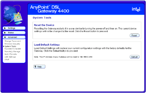
Resetting the gateway or reloading default settings
You can reset the gateway or reload the gateway default
settings using the System Tools screen, accessible from
the Advanced menu.
Related topics •See Accessing advanced configuration options on
page 72.
•See Changing the gateway password on page 74.
•See Specifying wireless security settings on page 76.
•See Exposing a computer outside the firewall on
page 81.
•See Enabling remote access on page 83.
•See Specifying the Host and Domain names on page
85.
•See Specifying LAN and DHCP settings on page 87.
•See Disabling Universal Plug and Play (UPnP) on
page 90.
Chapter 4 – Using Advanced Configuration Options
Copyright © 2002 Intel Corporation
80
Step-by-step To reset the gateway or reload its default settings:
1Click the Advanced menu to expand its selections.
2Click System Tools.
The following appears.
3Do one of the following:
•Click Reset. The gateway is restarted using your
previously saved configuration.
•Click Default. The gateway is restarted using the
factory default configuration and IP address.

Chapter 4 – Using Advanced Configuration Options
Copyright © 2002 Intel Corporation 81
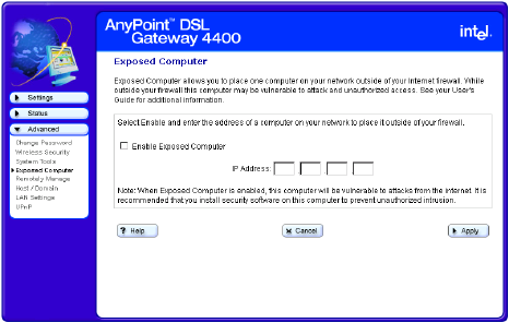
Exposing a computer outside the firewall
You can specify one computer on your network to be
placed outside the gateway’s built-in firewall using the
Exposed Computer screen, accessible from the
Advanced menu.
CAUTION Any computer you place outside the
gateway’s built-in firewall may be
vulnerable to attacks and unauthorized
access.
Related topics •See Accessing advanced configuration options on
page 72.
•See Changing the gateway password on page 74.
•See Specifying wireless security settings on page 76.
•See Resetting the gateway or reloading default
settings on page 79.
•See Enabling remote access on page 83.
•See Specifying the Host and Domain names on page
85.
•See Specifying LAN and DHCP settings on page 87.
•See Disabling Universal Plug and Play (UPnP) on
page 90.
Chapter 4 – Using Advanced Configuration Options
Copyright © 2002 Intel Corporation
82
Step-by-step To expose a computer on your network outside the
gateway’s firewall:
1Click the Advanced menu to expand its selections.
2Click Exposed Computer.
The following appears.
3Click (select) the Enable Exposed Computer
checkbox.
4Enter the IP address of the computer to be exposed
in the IP Address field.
5Click Apply.
Chapter 4 – Using Advanced Configuration Options
Copyright © 2002 Intel Corporation 83
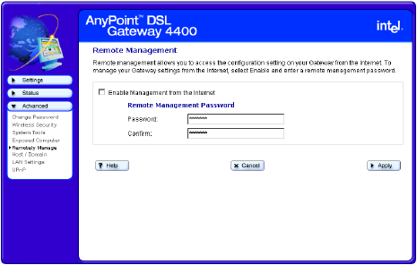
Enabling remote access
You can allow your ISP to access your gateway remotely
for troubleshooting using the Remote Management
screen, accessible from the Advanced menu.
Related topics •See Accessing advanced configuration options on
page 72.
•See Changing the gateway password on page 74.
•See Specifying wireless security settings on page 76.
•See Resetting the gateway or reloading default
settings on page 79.
•See Exposing a computer outside the firewall on
page 81.
•See Specifying the Host and Domain names on page
85.
•See Specifying LAN and DHCP settings on page 87.
•See Disabling Universal Plug and Play (UPnP) on
page 90.
Step-by-step To enable remote access:
1Click the Advanced menu to expand its selections.
2Click Remotely Manage.
The following appears.
Chapter 4 – Using Advanced Configuration Options
Copyright © 2002 Intel Corporation
84
3Select the Enable Remote Management from the
Internet checkbox.
4Enter the remote management password.
5Click Apply to save your settings.
More about Enabling remote access to your gateway can be a
security risk. Use extreme caution when enabling this
setting. Make sure that any request you receive to enable
remote access to your gateway is from someone
authorized to access or service your gateway.
Chapter 4 – Using Advanced Configuration Options
Copyright © 2002 Intel Corporation 85
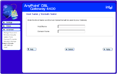
Specifying the Host and Domain names
You can specify the Host Name and Domain Name that
will be used by your gateway using the Host Name /
Domain Name screen, accessible from the Advanced
menu.
Related topics •See Accessing advanced configuration options on
page 72.
•See Changing the gateway password on page 74.
•See Specifying wireless security settings on page 76.
•See Resetting the gateway or reloading default
settings on page 79.
•See Exposing a computer outside the firewall on
page 81.
•See Enabling remote access on page 83.
•See Specifying LAN and DHCP settings on page 87.
•See Disabling Universal Plug and Play (UPnP) on
page 90.
Step-by-step To specify the Host Name and Domain Name:
1Click the Advanced menu to expand its selections.
2Click Host /Domain.
The following appears.
Chapter 4 – Using Advanced Configuration Options
Copyright © 2002 Intel Corporation
86
3Enter a host name in the Host Name field exactly as
it was given to you by your ISP.
4Enter a domain name in the Domain Name field
exactly as it was given to you by your ISP.
5Click OK.
Chapter 4 – Using Advanced Configuration Options
Copyright © 2002 Intel Corporation 87
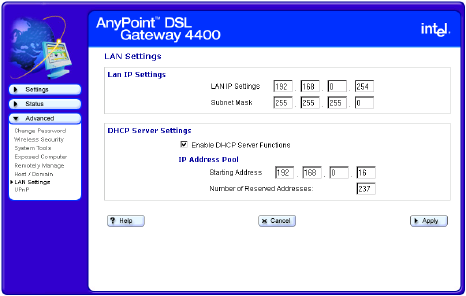
Specifying LAN and DHCP settings
You can specify or change the IP address of the gateway
or to enable/disable the gateway’s DHCP control using
the LAN Settings screen, accessible from the Advanced
menu.
Related topics •See Accessing advanced configuration options on
page 72.
•See Changing the gateway password on page 74.
•See Specifying wireless security settings on page 76.
•See Resetting the gateway or reloading default
settings on page 79.
•See Exposing a computer outside the firewall on
page 81.
•See Enabling remote access on page 83.
•See Specifying the Host and Domain names on page
85.
•See Disabling Universal Plug and Play (UPnP) on
page 90.
Chapter 4 – Using Advanced Configuration Options
Copyright © 2002 Intel Corporation
88
Step-by-step To specify or change the IP address of the gateway or to
enable/disable the gateway’s DHCP control:
1Click the Advanced menu to expand its selections.
2Click LAN Settings.
The following appears.
To specify or change the gateway’s IP address:
1Enter (or change) the LAN IP Address in the LAN IP
Settings field.
2Enter your Subnet Mask in the Subnet Mask field.
3Click Apply to save your settings.
To enable or disable the gateway’s DHCP control:
1Select the Enable DHCP Server Functions
checkbox if you are using the gateway to
automatically assign IP addresses to the computers
on your network (or deselect this checkbox to disable
the gateway’s DHCP control).
2Enter a starting address in the Starting Address
field.

Chapter 4 – Using Advanced Configuration Options
Copyright © 2002 Intel Corporation 89
3Enter a list of reserved addresses in the Number of
Reserved Addresses field.
4Click Apply to save your settings.
More about Following is an explanation of IP Address, Subnet Mask,
and DHCP Server.
Note Some computers on your network may need to
be restarted if DHCP is enabled on the gateway.
The DHCP Server then assigns each computer
an IP address.
IP Address The IP address of the gateway that the computers on your local
network use to communicate with the gateway and send traffic
to an external network or to another computer on your local
network.
Subnet Mask The Subnet Mask provides additional routing information for
traffic within your local network.
DHCP Server The DHCP server assigns IP addresses to each computer on
your local network. If the DHCP Server is enabled on the
gateway, then IP addresses are assigned automatically. If the
DHCP Server is not enabled, then each IP address for each
computer on your local network is entered individually and
remains static.
Chapter 4 – Using Advanced Configuration Options
Copyright © 2002 Intel Corporation
90
Disabling Universal Plug and Play (UPnP)
You can disable Universal Plug and Play (enabled, by
default) using the UPnP screen, accessible from the
Advanced menu. (Universal Plug and Play allows
supported operating systems and application software to
automatically configure a connection to the Internet.)
Related topics •See Accessing advanced configuration options on
page 72.
•See Changing the gateway password on page 74.
•See Specifying wireless security settings on page 76.
•See Resetting the gateway or reloading default
settings on page 79.
•See Exposing a computer outside the firewall on
page 81.
•See Enabling remote access on page 83.
•See Specifying the Host and Domain names on page
85.
•See Specifying LAN and DHCP settings on page 87.

Chapter 4 – Using Advanced Configuration Options
Copyright © 2002 Intel Corporation 91
Step-by-step To disable Universal Plug and Play (UPnP):
1Click the Advanced menu to expand its selections.
2Click UPnP.
The following appears.
3Unselect the Enable Universal Plug and Plan
(UPnP) checkbox to deselect this option.
4Click Apply to save your settings.
The Advanced Settings screen is displayed again,
showing the changes that were made.
Chapter 4 – Using Advanced Configuration Options
Copyright © 2002 Intel Corporation
92

Copyright © 2002 Intel Corporation 93
Chapter 5
Diagnostics and Troubleshooting
This chapter explains how to diagnose and troubleshoot
problems that may occur while using your gateway. It
explains how to get status information or system details,
how to run diagnostics, and how to troubleshoot
connection problems.
■Getting network status information
■Running Diagnostics
■Problems and solutions
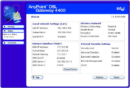
Chapter 5 – Diagnostics and Troubleshooting
Copyright © 2002 Intel Corporation
94
Getting network status information
You can view the LAN, WAN, Wireless Network, and
Firewall/Security settings of your gateway using the
Network Status screen, accessible from the Status menu.
Related topics •See Running Diagnostics on page 107.
•See Problems and solutions on page 108.
Step-by-step To view the network status information of your gateway:
1Click the Status menu to expand its selections.
2Click Network Status.
The following appears.
3Click Statistics to view detailed statistics on the
gateway.
4Click Details to view the interface configurations of
your gateway.

Chapter 5 – Diagnostics and Troubleshooting
Copyright © 2002 Intel Corporation 95
More about Following is an explanation of each setting.
Local Network Settings (LAN)
LAN IP address Description: The IP address is the
address of the gateway that the
computers on your local network use to
communicate with the gateway and send
traffic to an external network or to another
computer on your local network. To
specify or change the IP address of the
gateway, click Advanced > LAN
Settings. Click its Help button for more
information.
Default: 192.168.0.254
Subnet Mask Description: The Subnet Mask provides
additional routing information for traffic
within your local network. To specify or
change the subnet mask of the gateway,
click Advanced > LAN Settings. Click its
Help button for more information.
Default: 255.255.255.0
LAN DHCP Description: The DHCP Server assigns
IP addresses to each computer on your
local network. If the DHCP Server is
enabled on the gateway, then IP
addresses are assigned automatically. If
the DHCP Server is not enabled, then
each IP address for each computer on
your local network is entered individually
and remains static. To enable or disable
the gateway’s DHCP control, click
Advanced > LAN Settings. Click its
Help button for more information.
Default: Enabled
Internet Interface (WAN)

Chapter 5 – Diagnostics and Troubleshooting
Copyright © 2002 Intel Corporation
96
WAN IP address Description: The IP address is the
address of the Internet Interface. This is
the address that allows external traffic
(data) to reach your local network. This
information is provided to you by your
ISP.
Default: Provided by ISP.
Subnet Mask Description: The Subnet Mask
resembles an IP address and helps route
Internet traffic to your particular subnet or
local network. This information is
provided to you by your ISP.
Default: Provided by ISP
Default Gateway Description: The default gateway is the
IP address of the device on your ISP’s
network used to route traffic to the
Internet. The gateway sends all
messages that are not addressed to
devices on your local network to this
location. This information is provided to
you by your ISP.
Default: Provided by ISP
WAN DHCP Description: The WAN DHCP indicates
whether or not your ISP is generating IP
addresses.
Default: Disabled
DNS Servers 1 & 2 Description: The DNS Servers translate
a numeric IP address into a human-
readable address. For example,
192.168.0.254 is a numeric IP address,
and www.intel.com is a human-readable
address. These two fields show the IP
address of the DNS Servers at your ISP’s
site. This information is provided to you
by your ISP.
Default: Provided by ISP
Wireless Network

Chapter 5 – Diagnostics and Troubleshooting
Copyright © 2002 Intel Corporation 97
Wireless Networking Description: Indicates whether or not
Wireless Networking has been enabled.
To set up wireless networking, click
Settings > Wireless, then click the
Wireless Setup button to access the
Wireless Wizard. Click the Help button on
any of the Wireless Wizard’s screens for
more information.
Default: Enabled if configured.
Stealth Mode Description: Indicates whether or not
Stealth mode has been enabled. You
enable Stealth mode to prevent other
wireless devices from scanning for your
network (but does not prevent them from
connecting if they have the correct
settings and access privileges). To
enable Stealth mode, click Advanced >
Wireless Security, then select the
Stealth Mode option. Click its Help
button for more information.
Default: Normal.
Encryption Description: Specifies what type of
encryption has been selected. The
gateway and each adapter in the network
must have the same encryption keys. To
specify encryption, click Settings >
Wireless, then click the Wireless Setup
button to access the Wireless Wizard.
Click Next until you see the “Wireless
Settings – Encryption” screen. Click the
Help button on any of the Encryption
screens for more information.
Default: Depends on selection at setup.

Chapter 5 – Diagnostics and Troubleshooting
Copyright © 2002 Intel Corporation
98
Access Control List Description: Indicates whether or not an
Access Control List has been enabled.
The Access Control List, one of the
Advanced features, is used to create a
list of users that are either allowed
access to or prevented access from your
network. To create or enable an existing
Access Control List, click Advanced >
Wireless Security. Click its Help button
for more information.
Default: Disabled.
Firewall/Security Settings
Security Level Description: Specifies which one of the
three types of selectable security levels
has been selected. To specify a security
level, click Settings > Firewall. Click its
Help button for more information.
Default: Normal
Intrusion Detection Description: Indicates whether or not
intrusion detection has been enabled. To
specify intrusion detection settings, click
Settings > Firewall, then click the
Advanced button. Click its Help button
for more information.
Default: Enabled
Exposed Computer Description: Indicates whether or not a
computer on your network has been
selected to be exposed outside the
firewall. To expose a computer on your
network outside the gateway’s firewall,
click Advanced > Exposed Computer.
Click its Help button for more information.
Default: Disabled

Chapter 5 – Diagnostics and Troubleshooting
Copyright © 2002 Intel Corporation 99
Remote Management Description: Indicates whether or not
remote management of the gateway has
been enabled. To enable remote access,
click Advanced > Remotely Manage.
Click its Help button for more information.
Default: Disabled
UPnP Description: Indicates whether or not
Universal Plug and Play (UPnP) has
been enabled. To enable UPnP, click
Advanced > UPnP. Click its Help button
for more information.
Default: Enabled

Chapter 5 – Diagnostics and Troubleshooting
Copyright © 2002 Intel Corporation
100
Getting status details
You can view the interface configuration of your gateway
using the Details screen, accessible from the Network
Status screen.
Related topics •See Getting network status information on page 94.
Step-by-step To view the interface configuration of your gateway:
1Click the Status menu to expand it selections.
2Click Network Status.
The following appears.
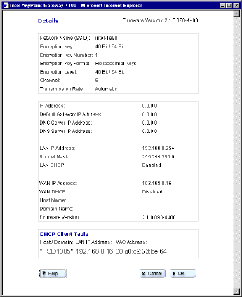
Chapter 5 – Diagnostics and Troubleshooting
Copyright © 2002 Intel Corporation 101
3Click Details.
The following appears.

Chapter 5 – Diagnostics and Troubleshooting
Copyright © 2002 Intel Corporation
102
More about Following is an explanation of each setting.
Network Name (SSID) Description: Indicates the Network
Name (also known as SSID, ESSID,
BSSID, or network code) currently in use.
The Network Name, used in conjunction
with the Encryption Key allows all
wireless devices on the same network to
communicate with each other. To specify
a Network Name, click
Settings>Wireless, click the Wireless
Setup button, then click Next until you
see the "Network Name" screen. Click its
Help button for more information.
Default: Intel-nnnn (where nnnn is a
hexadecimal value.)
Encryption Key Description: Indicates the Encryption
Key currently in use. An Encryption Key
is used to implement security and protect
your information in a wireless network.
The Encryption Key, used in conjunction
with the Network Name allows all
wireless devices on the same network to
communicate with each other. To specify
an Encryption Key, click
Settings>Wireless, click the Wireless
Setup button, then click Next until you
see the "Encryption" screen. Click its
Help button for more information.
Default: 40 Bit/64 Bit
Encryption Key Number Description: Indicates which of four
possible sets of encryption keys is
currently in use. To specify a Key
Number, click Settings>Wireless, click
the Wireless Setup button, then click
Next until you see the "Encryption"
screen. Click its Help button for more
information.
Default: 1

Chapter 5 – Diagnostics and Troubleshooting
Copyright © 2002 Intel Corporation 103
Encryption Key Format Description: Indicates which Encryption
Key format is currently in use. The
Encryption Key Format indicates how the
Encryption Key is generated (from text,
from Ascii, from Hexadecimal keys, and
so on). To specify a Key Format, click
Settings>Wireless, click the Wireless
Setup button, then click Next until you
see the "Encryption" screen. Click its
Help button for more information.
Default: Hexadecimal Keys
Encryption Level Description: Indicates which Encryption
Level is currently in use. The Encryption
Level indicates the bit size used to
generate the key. To specify an
Encryption Level, click
Settings>Wireless, click the Wireless
Setup button, then click Next until you
see the "Encryption" screen. Click its
Help button for more information.
Default: 40 Bit/64 Bit
Channel Description: Indicates which Channel is
currently in use. You can select a
different channel if you experience
interference. To select a different
channel, click Settings>Wireless, click
the Wireless Setup button, click Next
until you see the "Network Name" screen,
then click Advanced. Click its Help
button for more information.
Default: 6

Chapter 5 – Diagnostics and Troubleshooting
Copyright © 2002 Intel Corporation
104
Transmission Rate Description: Indicates the transmission
rate currently in use. You should never
need to change this value. However, it
may be possible for you to extend the
wireless communication distance by
decreasing this value. To do so, click
Settings>Wireless, click the Wireless
Setup button, click Next until you see the
"Network Name" screen, then click
Advanced. Click its Help button for more
information.
Default: Automatic
IP Address Description: The IP address is the
address of the Internet Interface. This is
the address that allows external traffic
(data) to reach your local network. This
information is provided to you by your
ISP.
Default: Provided by ISP
Default Gateway IP Address Description: Indicates the IP address of
the device on your ISP’s network used to
route traffic to the Internet. The gateway
sends all messages that are not
addressed to devices on your local
network to this location. This information
is provided to you by your ISP.
Default: Provided by ISP
DNS Server IP address Description: The DNS Servers translate
a numeric IP address into a human-
readable address. For example,
192.168.0.254 is a numeric IP address,
and www.intel.com is a human-readable
address. These two fields show the IP
address of the DNS Servers at your ISP's
site. This information is provided to you
by your ISP.
Default: Provided by ISP

Chapter 5 – Diagnostics and Troubleshooting
Copyright © 2002 Intel Corporation 105
LAN IP address Description: The IP address is the
address of the gateway that the
computers on your local network use to
communicate with the gateway and send
traffic to an external network or to another
computer on your local network. To
specify or change the IP address of the
gateway, click Advanced > LAN
Settings. Click its Help button for more
information.
Default: 192.168.0.254.
Subnet Mask Description: The Subnet Mask provides
additional routing information for traffic
within your local network. To specify or
change the subnet mask of the gateway,
click Advanced > LAN Settings. Click its
Help button for more information.
Default: 255.255.255.0.
LAN DHCP Description: The DHCP Server assigns
IP addresses to each computer on your
local network. If the DHCP Server is
enabled on the gateway, then IP
addresses are assigned automatically. If
the DHCP Server is not enabled, then
each IP address for each computer on
your local network is entered individually
and remains static. To enable or disable
the gateway's DHCP control, click
Advanced > LAN Settings. Click its
Help button for more information.
Default: Enabled
WAN IP Address Description: The IP address is the
address of the Internet Interface. This is
the address that allows external traffic
(data) to reach your local network. This
information is provided to you by your
ISP.
Default: Provided by ISP

Chapter 5 – Diagnostics and Troubleshooting
Copyright © 2002 Intel Corporation
106
WAN DHCP Description: The default gateway WAN
DHCP is the DNS name that represents
the IP address of the device on your
ISP's network used to route traffic to the
Internet. The gateway sends all
messages that are not addressed to
devices on your local network to this
location. This information is provided to
you by your ISP.
Default: Client
Host Name Description: The Host Name used by
your gateway. To change the Host Name,
click Advanced > Host/Domain. Click its
Help button for more information
Default: Blank
Domain Name Description: The Domain Name used by
your gateway. To change the Domain
Name, click Advanced > Host/Domain.
Click its Help button for more information
Default: Blank
Firmware Version Description: Lists the currently installed
firmware.
Default: Currently installed firmware
DHCP Client Table Description: List the Host/Domain, LAN
IP Address, and MAC Address of the PCs
connected on the LAN.
Default: N/A.
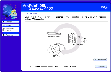
Chapter 5 – Diagnostics and Troubleshooting
Copyright © 2002 Intel Corporation 107
Running Diagnostics
You can run diagnostics at any time on your gateway and
associated network connections using the Diagnostics
screen, accessible from the Status menu.
Related topics •See Getting network status information on page 94.
•See Problems and solutions on page 108.
Step-by-step To run diagnostics:
1Click the Status menu to expand its selections.
2Click Diagnostics.
The following appears.
3Click Run Diagnostics – your gateway is tested first,
then the link to your DSL modem, then the link to
your ISP.
4[Optional] Click Troubleshoot, if any test fails.
Chapter 5 – Diagnostics and Troubleshooting
© 2002 Intel Corporation
108
Problems and solutions
Use this chapter to identify and troubleshoot connection
problems.
Problem I can’t connect to the gateway
Solution A Wired Network
• Verify that the gateway power is turned ON – the
gateway’s Power LED (far left LED – separate from
the bank of eight LEDs) should be illuminated.
• Verify that the System LED (far left in the bank of
eight LEDs) is blinking green, indicating the gateway
is operating correctly.
• Verify that the System LED is NOT blinking yellow.
The gateway’s System LED will blink yellow if the
gateway detects another DHCP server connected to
one of the four Ethernet connectors. Disconnect each
Ethernet cable, one at a time, until the system returns
to blinking green. Change the PC you’ve identified as
a DHCP server to a DHCP client.
• Check your connections – see the diagrams in the
Installation Guide. You may need to replace the
cable associated with the connection if the LED
differs from the description below:
• Verify that the Ethernet LED (one of 4 LEDs on
the right) is solid or blinking, green or yellow
(indicating link at 10 or 100 Mbps)
• Can you access the Gateway Internet Setup Wizard
screen? – From your Web browser, enter the Internet
address, http://192.168.0.254 (this is the default
value – assumes it has not been changed in the
Wireless Gateway configuration software). If the
welcome screen does not appear, then make sure
the “IP addressing” on the network adapter to which
the gateway is connected is set as follows:
Chapter 5 – Diagnostics and Troubleshooting
© 2002 Intel Corporation 109
This assumes that the Gateway DHCP is still on – which
it is on by default, when in gateway mode.
• The adapter is set to obtain an IP address
automatically
You can verify the PC adapter is set correctly by
going to a MSDOS or command prompt. At the
command prompt type:
ipconfig /all
(leave a space before /all)
• Verify the default Gateway address is
192.168.0.254. If the IP address is correct, but
the Welcome screen still doesn’t come up, then
restart your PC.
• In your Web browser, specify to not use a proxy
server when connecting to the Internet (refer to
your browser’s help pages for information).
• The adapter is set to obtain a DNS address
automatically for Windows 2000
• The adapter has DNS disabled for Windows 98,
Windows 98SE, or Windows ME.
Solution B Wireless Network
• Follow the above solutions for a wired network
• Verify that there is a wireless client connected – the
gateway’s Wireless Link LED (third from the right in
the bank of eight LEDs) will blink green when it
detects traffic.
• Verify that your wireless adapter is set to operate in
Infrastructure mode and uses the same Network ID
(SSID) code and encryption settings as the gateway.
Problem I can’t share files and printers among the PCs on my
network

Chapter 5 – Diagnostics and Troubleshooting
© 2002 Intel Corporation
110
Solution • Verify that each PC on the network can connect to
the gateway as described above.
• Verify that each PC can “see” every other PC on the
network. For instance, on Windows 2000 you would
click “My Network Places” to locate each PC by its
system name (on Windows 9x, click “Network
Neighborhood”).
• If you add a third-party firewall to a PC, you may be
required to configure it to allow internal network
communication. Refer to the firewall documentation
for assistance.
• Because the operating system network browser can
take up to 15 minutes to refresh using TCP/IP, make
sure that all PCs have the Microsoft IPX/SPX
protocol properly installed with “Frame type” set to
802.3 on the protocol’s Advanced tab.
• Also make sure that Client for Microsoft Networking
and File and Print sharing are properly installed, as
follows:
Windows 98 or ME
1Click Start > Settings > Control Panel > Network.
2To add file and print sharing, click File and Print
Sharing and then click OK.
3Follow the onscreen prompts to insert your Windows
CD and allow your PC to copy the needed files.
4To add a client such as Client for Microsoft Networks
or a network protocol, click Add.
5Choose from among the subsequent dialogs
according to what you wish to add and then click OK.
6Follow the screen prompts to insert your Windows
CD and allow your PC to copy the needed files.
Note If you are using AnyPoint® adapters, this is
all taken care of automatically.
Chapter 5 – Diagnostics and Troubleshooting
© 2002 Intel Corporation 111
Windows 2000
1Click Start > Settings > Control Panel > Network
and Dial-up Connections.
2To add file and print sharing or a client or protocol,
right-click the icon representing the network
connection your changes should apply to.
3Click Properties.
4Click the Install button and select either client,
service or protocol according to what you wish to
add.
5Choose from among the following dialogs then click
OK
6Follow the screen prompts to insert your CD and
allow your PC to copy the needed files.
Windows XP
1Click Start > Control Panel > Network
Connections.
2To add file and print sharing or a client or protocol,
right-click the icon representing the network
connection your changes should apply to.
3Click Properties.
4Click the Install button and select either client,
service or protocol according to what you wish to
add.
5Choose from among the following dialogs then click
OK
• Try again to see that each PC can “see” every other
PC on the network. For instance, on Windows 2000
you would click “My Network Places” to locate each
Chapter 5 – Diagnostics and Troubleshooting
© 2002 Intel Corporation
112
PC by its system name (on Windows 9x, you would
click “Network Neighborhood”).
• When other PCs become visible, use standard
procedures to share and map drives and printers.
Problem I can’t connect to the Internet through my gateway
The assumption for the solution below is that you were
able to connect to the Internet before you inserted the
gateway into your network.
Solution • Verify that each PC on the network can connect to
the gateway.
• Verify that the gateway Internet LED (second LED
from the left in the bank of eight LEDs) is either solid
or blinking green. If the Internet LED is red, verify that
you have a standard phone cable connected
between the DSL port on the gateway and your DSL
service outlet.
• Verify all your connections are securely attached.
• Unplug the power cord from the gateway.Reapply
power in the following order:
• Reapply power to the gateway. Confirm the
Internet LED is solid or blinking green.
• If the Internet LED on the gateway is off, unplug
power from the gateway, attach a new cable
between the gateway and your DSL service
outlet. Turn power back on to the gateway and
verify the Internet LED is solid green.
Problem I’ve made changes to the gateway, clicked Save and
Restart, and now can’t connect to the gateway.
Solution There are several possible solutions. See the following:
• You’ve changed a setting on the Gateway, such as
the Gateway IP address, disabled the DHCP server,
changed mode, or wireless settings. Restart your PC

Chapter 5 – Diagnostics and Troubleshooting
© 2002 Intel Corporation 113
and try connecting to the gateway again. If you still
cannot connect to the gateway, reset the gateway to
factory defaults. Locate the reset switch (next to the
antenna on the rear panel). Press the reset switch,
using a paper clip, for 5 seconds.
• Verify you can connect to the gateway from a wired
connection. If you changed wireless settings, you can
verify the settings you’ve changed from a wired PC.
See Getting network status information on page 94.
•See I can’t connect to the gateway on page 108
Consult the solution that applies to your network
(wired or wireless network).
Problem I’m experiencing intermittent connections
Solution You are likely experiencing interference from other
wireless devices (such your microwave oven or cordless
phone).
• Make sure the antenna on the gateway is extended
(and on your USB adapters, if applicable).
• Increase the distance between wireless devices (for
instance, don’t position your gateway or adapters
near your cordless phone’s base).
• If you live in a multi-level dwelling, change the
direction of the antenna on the Gateway to point
directly towards you (when facing the rear panel).
This will provide better coverage for multilevel floors.
• Switch to another channel on your cordless phone, if
possible.
• Change the channel on the gateway to channel 1, 6,
or 11 (these channels will not overlap each other).
Note If you change the channel on your gateway,
you will need to reboot all your wireless
connected PCs.
Chapter 5 – Diagnostics and Troubleshooting
© 2002 Intel Corporation
114
Problem I’m having trouble connecting to my Internet game
server
Solution Consult your documentation for your game to determine
the correct ports to open for your game to operate
correctly behind a firewall.
Problem I’m having trouble getting AOL working
Solution • Configure the AOL software connection setup for a
TCP/IP (direct) or LAN connection. Save your
settings then try again.
You may not be able to have more than one instance
of the AOL software open at the same time, for a
given account. That is, if you are currently accessing
the Internet on a PC using the AOL software, you
may need to use another browser or another AOL
account to access the Internet on another PC.
• If you still cannot connect, then verify that you can
access the Internet in general via another Web
browser (Netscape, Internet Explorer).
• If you are able to access the Internet, but cannot
access AOL then refer to your AOL documentation
for help and technical support information.
Problem I’m having trouble getting my e-mail working
Solution • Verify that you have entered the correct Domain
Name (DNS entry) from your Install Information
Worksheet. If it is correct, you should be able to
browse the Internet.
• Verify that each PC connected to the gateway can
access the Internet. See I can’t connect to the
Internet through my gateway on page 112

Chapter 5 – Diagnostics and Troubleshooting
© 2002 Intel Corporation 115
• Check the e-mail settings provided by your ISP on
each PC.
Problem I’m using a third-party adapter and I cannot access
the gateway or the Internet
Solution Use the following instructions to make sure the network
properties are set correctly for obtaining an IP address.
Setting or checking your IP address
Depending on your operating system, follow the
appropriate set of instructions.
Windows 98 and ME
1Click Start > Settings > Control Panel > Network.
2Select the TCP/IP --> [the name of the Network
Adapter]. For example, Intel® AnyPoint® Wireless II
Adapter.
3Click Properties.
4Click the IP Address tab.
5Make sure that the Obtain an IP address
automatically option is selected.
6On the DNS Configuration tab, make sure Disable
DNS is selected.
7If one or both are not selected, select them, and then
restart the PC.
Note If you can access the Internet, the problem is
NOT in the gateway.
Chapter 5 – Diagnostics and Troubleshooting
© 2002 Intel Corporation
116
Windows 2000
1Click Start > Settings > Network and Dial-up
Connections.
2Right-click [the name of the Network Adapter], for
example, Intel AnyPoint Wireless II Adapter and
select Properties.
3In the Local Area Connection Properties dialog box,
click Internet Protocol (TCP/IP).
4Click Properties.
5Make sure that the Obtain an IP address
automatically option is selected.
6Make sure that the Obtain DNS server address
automatically option is selected.
7If one or both are not selected, select them and
restart the PC after you make the change.
Windows XP
1Click Start > Control Panel > Network
Connections, and then click Network Connections.
2Right-click [the name of the Network Adapter], for
example, Intel AnyPoint Wireless II Adapter and
select Properties.
3In the Local Area Connection Properties dialog box,
click Internet Protocol (TCP/IP).
4Click Properties.
5Make sure that the Obtain an IP address
automatically option is selected.
6Make sure that the Obtain DNS server address
automatically option is selected.
7If one or both are not selected, select them and
restart the PC after you make the change.
Problem I’m using Internet Connection Sharing (ICS) and
don’t know how to remove it.
Chapter 5 – Diagnostics and Troubleshooting
© 2002 Intel Corporation 117
Solution Internet Connection Sharing is a software method for
sharing an Internet connection. The gateway provides
this method now. To manually remove ICS, use the
following instructions for your operating system:
Windows 98
1Click Start > Settings > Control Panel > Add/
Remove Programs.
2Click the Windows Setup tab.
3Click Internet Tools and then click Details.
4Select Internet Connection Sharing to remove the
check mark, and then click OK.
5Click Apply to save your changes.
Windows removes the components and prompts you
to restart your PC.
6Click Yes to restart.
Windows ME
1Click Start > Settings > Control Panel > Add/
Remove Programs.
2Click the Windows Setup tab, click
Communications, and then click Details.
3Select Internet Connection Sharing to remove the
check mark, and then click OK.
4Click OK.
Windows removes the components and prompts you
to restart your PC.
5Click Yes to restart.

Chapter 5 – Diagnostics and Troubleshooting
© 2002 Intel Corporation
118
Windows 2000
1Click Start > Control Panel > Network and Dial-Up
Connections.
2Right-click the dial-up, VPN, or incoming connection
you have shared, and then click Properties.
3On the Sharing tab, remove the Enable Internet
connection sharing for this connection check box,
and click OK
Windows XP
1Click Start > Control Panel > Network
Connections.
2Click the connection you have shared, and then
under Network Tasks, click Change settings of
this connection.
3On the Advanced tab, remove the Allow other
network users to connect through this
computer’s Internet connection check box, and
click OK
Problem My Internet game, that is Universal Plug and Play
aware, does not work.
Solution Enable Universal Plug and Play on the gateway.
You also may need to enable UPnP on your Windows
system. See the following problem and solution.
Problem I’m trying to use UPnP. How do I enable it?
Note Windows XP and Me editions support UPnP.
Other versions of Windows will require a 3rd
party product to use UPnP.
Chapter 5 – Diagnostics and Troubleshooting
© 2002 Intel Corporation 119
Solution Instructions for installing UPnP on Windows XP and
Windows ME follows. Other versions of Windows will
require a 3rd party product to use UPnP.
Windows ME
1Click Start > Settings > Control Panel > Add/
Remove Programs.
2Click the Windows Setup tab.
3In the Components list, select the Communications
check box, and then click Details.
4Make sure the Universal Plug and Play check box is
selected and then click OK.
5Click Apply to save your changes.
Windows installs the components. You are prompted
to restart your PC.
6Click Yes to restart.
Windows XP
1Click Start > Control Panel > Add or Remove
Programs, and then in the left channel, click Add/
Remove Windows Components.
2In the Components list, select the Networking
Services check box, and then click Details.
3Select Universal Plug and Play, and then click OK.
4Click Next and then Finish.
Problem My Internet game does not work
Solution You may need to enable a custom rule on the gateway.
Chapter 5 – Diagnostics and Troubleshooting
© 2002 Intel Corporation
120
If all else fails
If none of the previous problems and solutions seem to
match your situation, try the following:
• Unplug the power cord from the gateway, wait at
least 5 seconds, then plug the power cord back in.
• Reset the gateway.
• If you cannot get to the system tools screen to
perform this reset then unplug the power cord from
the gateway, wait at least 5 seconds, then plug the
power cord back in.
• Restore the gateway to its original factory defaults.
Reconfigure the gateway using the gateway configuration
software.
Reading the gateway indicator lights
As an initial operational check of your gateway, check the
indicator lights. The indicators are described in Chapter 1
of the User’s Guide.
Reading settings and device status
If you are having connection problems with your
broadband modem, or the wired or wireless network,
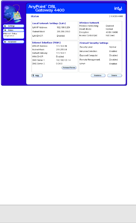
Chapter 5 – Diagnostics and Troubleshooting
© 2002 Intel Corporation 121
check the Status screen. From this screen, you can see if
your connections are active or not connected.
1Click the Status menu to expand its selections.
2Click Network Status.
The following appears.
3Click Statistics to view detailed statistics on the
gateway.
4Click Details to view the interface configurations of
your gateway.
Loading
default
settings
You can load default settings if you want to create a new
configuration or want to start from known settings.
1Click the Advanced menu to expand its selections.
2Click System tools.
3Click Default.
Your gateway now has the initial factory settings, but
any firmware upgrades will remain.
Note The device IP address will be reset to
192.168.0.254
Chapter 5 – Diagnostics and Troubleshooting
© 2002 Intel Corporation
122
Resetting the
gateway
When you click Reset, you will restart your gateway using
the current settings. The gateway will show the initial
Wireless Gateway screen. Clicking Reset from the
System Tools screen is useful if you have mounted the
unit on the wall or ceiling and cannot physically access
the Reset button.
1Click the Advanced menu to expand its selections.
2Click System tools.
3Click Reset.
You gateway will restart with your current settings.

Copyright © 2002 Intel 123
Chapter 6
Glossary
This section contains a list of network and computer
related terms with definitions.
Chapter 6 – Glossary
Copyright © 2002 Intel Corporation
124
Glossary
802.11b A specific networking standard created by IEEE that
defines engineering design parameters for high-speed
wireless data transmission. The 802.11b standard allows
different manufacturers to create wireless products that
are compatible with each other.
Ad Hoc Mode Peer-to-Peer
A software setting for 802.11b wireless adapters.
Adapter Also network adapter or NIC
A hardware device that allows your PC to connect to a
network.
Access Point
(AP)
A hardware device that serves as a communications
“hub” for 802.11b wireless PCs and can also provide a
connection to a wired network. An AP can double the
range of wireless client PCs and provide enhanced
security.
ASCII
characters
Any printable alpha-numeric character.
DHCP Dynamic Host Configuration Protocol. A TCP/IP protocol
that defines a way to automatically assign IP addresses
to computers on a network. IP addresses are managed
by a DHCP server on the network. When a computer
starts, it requests an IP address from the server. The
server leases an address for a set time. After that time,
the computer makes a new request. When a Windows
computer is configured to obtain an IP address
automatically, it attempts to get an address from a DHCP
server. Windows 2000 and Windows NT servers include
DHCP server software that can provide this service.
Network appliances that rely on TCP/IP often include a
DHCP server.
Chapter 6 – Glossary
Copyright © 2002 Intel Corporation 125
Driver (Device
Driver)
Special software programs required for any device to
install properly on a PC. Devices include network
adapters, printers, scanners, modems, audio cards, CD
drives, monitors etc. Drivers enable the device to
coordinate its activities with the PC to which it is
attached.
DNS Domain Name System. A naming service used to identify
servers connected to the Internet. Every domain name is
unique. DNS servers maintain a database of names and
associated IP addresses, so Web users can browse to a
domain name and reach the server at the associated IP
address.
Encryption A method of converting all of the information that is
transmitted over a wireless network into a form that
cannot be read by unauthorized persons. Encryption
provides additional data security in 802.11b wireless
networks.
Ethernet Ethernet is defined by the IEEE 802.3 standard. Ethernet
networks operate at speeds of 10Mbps and above using
CSMA/CD (Carrier-Sense Multiple Access) to run over
cables such as 10BaseT.
Ethernet
address (MAC
address)
Each computer on an Ethernet network has its own
unique, pre-programmed Media Access Control (MAC)
address. This 12-digit hexadecimal address is encoded
into the circuitry of the computer's network adapter when
it is manufactured. Other devices on the network use this
address to identify the computer. This address is not the
same as the IP address that is assigned to computers on
TCP/IP networks. On these networks, the IP address is
associated with the MAC address to enable network
communication.
Firewall Software on a network gateway that protects the
computers on a private network from the Internet. The
Chapter 6 – Glossary
Copyright © 2002 Intel Corporation
126
firewall can also control what Internet resources local
network computers can access.
Gateway A network device that provides an entrance to another
network.
Hexadecimal A base-16 number system. That is, a numbering system
that counts 16 base unit numbers before adding a new
digit. Hexadecimal numbers use 0-9 and then the letters
A-F. For example, the letter A in hexadecimal represents
10 in decimal, F is 15 in decimal, and the hexadecimal
number 10 is 16 in decimal.
Hub The central connection point for network cables that
connect to computers or other devices on a network. With
an 8-port hub, you can connect cables to 8 computers
Infrastructure
Mode
A software setting for 802.11b wireless adapters allowing
connectivity to a central device, either a gateway or an
access point. The gateway or access point handles the
communication between PCs and often manages the
Internet connection. See Ad Hoc and Access Point.
IEEE The Institute of Electrical and Electronics Engineers.
ISP Internet Service Provider
An organization that provides access to the Internet.
Users connect with the ISP using a conventional or
broadband modem.
LAN Local Area Network
A computer network that serves users within a defined
location. The benefits include the sharing of Internet
access, files and equipment like printers and storage
devices. LANs use Ethernet cabling, existing phone lines
or radio waves to transmit data between the PCs. LANs
include home and small-business networks.
Chapter 6 – Glossary
Copyright © 2002 Intel Corporation 127
Mbps Megabits per second, a measure of data transmission
speed.
NAT Network Address Translation. A service that translates
your local private IP addresses to a public Internet
address so your privately addressed network can
connect to the public Internet. NAT simplifies network
setup and adds a measure of security to your network
because your private network addresses are never seen
on the Internet.
Peer-to-Peer See Ad Hoc.
Profiles
(Network
Profiles)
A collection of software settings and network
identification information that is unique for each network.
Protocols
(Network
Protocols)
Define the rules for all aspects of data communication
just like a written language uses rules for spelling,
sentence structure, etc. Protocols describe the way data
is organized, transmitted and received. The TCP/IP
protocol is one of the most common.
Resources
(Network
resources)
Software or hardware shared by the users of a network.
Resources can include software applications,
documents, digital pictures and music, games, numeric
data, and devices such as printers, modems and disk
drives.
Roaming Moving seamlessly from one access point coverage area
to another with no loss in connectivity.
SSID Service Set Identifier. To communicate with each other,
all wireless devices on the same network must use the
same SSID. The SSID allows two or more wireless
networks to function in the same vicinity without
interfering with each other. The SSID can be a word or a
combination of letters and numbers.
Chapter 6 – Glossary
Copyright © 2002 Intel Corporation
128
Subnet A distinct separate part of a computer network. Often,
computers in one building or location form a subnet.
Dividing a large network into subnets isolates network
traffic, enhances network performance, and provides a
mechanism for organizing the network in a logical
manner. You divide a network into subnets by connecting
network segments with a router. On a TCP/IP network, IP
routers connect subnets together.
Subnet mask A mask used to determine the subnet for an IP address.
IP addresses have two parts: a subnet address and the
computer address. The subnet mask determines what
part of the IP address is the subnet address. For
example, if you have a subnet mask of 255.255.0.0, the
first two numbers in your IP address are the subnet
address. The last two numbers are your computer's
address on the local network. Your computer uses the
subnet mask to decide whether to send data to another
computer on the local network, or to send the data to the
address specified by your default gateway. If the subnet
part of the address you are sending data to matches your
IP address, then your computer tries to send the data on
the local network. If these do not match, then the
computer you are sending data to is on another subnet
(probably on the Internet), so your computer sends the
data to your default gateway, and the gateway forwards it
on to the Internet.
Switch Similar to a hub, a switch is a central connection point for
network cables that connect to computers or other
network devices. However, when two devices
communicate through a switch, it sends signals directly
from one port to the other port, instead of transmitting to
all ports, like a hub. You can connect a computer, a hub,
or a switch to each port on a switch.
TCP/IP Transmission Control Protocol/Internet Protocol. The
protocol that computers use to communicate over the
Internet. TCP determines how a computer breaks up data
Chapter 6 – Glossary
Copyright © 2002 Intel Corporation 129
into small units, called packets, to be sent to another
computer and how the receiving computer reassembles
the packets into a single file. IP determines how the
packets are routed across the Internet.
UPnP Universal Plug and Play (UPnP) is a standard that uses
Internet and Web protocols to enable devices such as
PCs, peripherals, and wireless devices to be plugged into
a network and automatically know about each other.
Chapter 6 – Glossary
Copyright © 2002 Intel Corporation
130

Copyright © 2002 Intel Corporation 131
Chapter 7
Regulatory Compliance Statements
This chapter contains the following agency notices:
■Safety compliance statements
■Emissions compliance statements
■RF exposure compliance statements
■Telecom compliance statements
■Canadian compliance statements
■European Union compliance statements
■Product Ecology Statements
132
Safety compliance statements
• This product complies with the safety requirements for
Information Technology Equipment and is Listed by
Underwriters Laboratories, Inc. to UL 60950 and CSA
C22.2 No. 950 for the U.S. and Canada.
• This modem is for use only with listed compatible
computers.
• CAUTION: To reduce the risk of fire, use only No. 26
AWG or larger telecommunication line cord.
•Français ATTENTION: Pour réduire le risque d'incendie,
utiliser uniquement des conducteurs de télé-
communications 26 AWG ou de section supérieure.
• NOTICE: This product does not provide primary
telephone circuit protection . This primary circuit
protection should be provided by the telephone company
at the building connection. In the U.S. and Canada, this
protection is provided by the telephone company under
federal regulations. However, for the European Union
and other geographies, we cannot confirm this protection
has been provided.
Emissions compliance statements
• This product has been tested and found to comply with
the limits for a Class B digital device pursuant to Part 15
of the FCC rules. These limits are designed to provide
reasonable protection against harmful interference when
the equipment is operated in a residential environment.
• This product generates, uses, and can radiate radio
frequency energy and, if not installed and used in
accordance with the instruction manual, may cause
harmful interference to radio communications. However,
there is no guarantee that interference will not occur in a
particular installation. If this equipment does cause
harmful interference to radio or television reception,
which can be determined by turning this equipment off
and on, the user is encouraged to try to correct the
Chapter 7 – Regulatory Compliance Statements
Copyright © 2002 Intel Corporation 133
interference by one or more of the following
measures:
• Change the direction of the radio or TV antenna.
• To the extent possible, relocate the radio, TV, or
other receiver away from the product.
• Plug the host computer into a different electrical
outlet so that the computer and the radio or TV
are on different electrical branch circuits.
• This device complies with Part 15 of the FCC Rules.
Operation is subject to the following two conditions:
(1) This device may not cause harmful interference,
and (2) this device must accept any interference
received, including interference that may cause
undesired operation.
• CAUTION: If you make any modification to the
equipment not expressly approved by Intel®, you
could void your authority to operate the equipment.
RF exposure compliance statements
Notice: Install or position the Intel AnyPoint® DSL
Gateway Model 4400 so that the antenna is at least 8
inches (20 cm.) from the user or other persons. Failure to
locate the antenna at this minimum distance may result in
exceeding the FCC limits for human exposure to RF
(radio frequency) energy. Also, do not operate in
conjunction with any other antenna or transmitters.
Telecom compliance statements
• This equipment complies with Part 68 of the FCC
Rules and the requirements adopted by ACTA. On
the bottom side of this equipment is a label that
contains, among other information, a product
identifier in the format US: EJMDLNANXXXX. If
Chapter 7 – Regulatory Compliance Statements
Copyright © 2002 Intel Corporation
134
requested, this number must be provided to the
telephone company.
• This equipment is provided with an RJ11C Universal
Service Order Codes (USOC) jack for connection to
the telephone network.
• A plug and jack used to connect this equipment to the
premises wiring and telephone network must comply
with the applicable FCC Part 68 rules and
requirements adopted by the ACTA. A compliant
telephone cord and modular plug is provided with this
product. It is designed to be connected to a
compatible modular jack that is also compliant. See
installation instructions for details.
• There is no Ringer Equivalence Number on this
equipment (Intel ADSL digital modem). For all ADSL
digital modems, the Ringer Equivalence Number
(REN) is not applicable.
• If this equipment (Intel ADSL digital modem) causes
harm to the telephone network, the telephone
company will notify you in advance that temporary
discontinuance of service may be required. But if
advance notice is not practical, the telephone
company will notify the customer as soon as
possible. Also, you will be advised of your right to file
a complaint with the FCC if you believe it is
necessary.
• The telephone company may make changes in its
facilities, equipment, operations or procedures that
could affect the proper functioning of the equipment.
If this happens, the telephone company will provide
advance notice in order for you to make necessary
modifications to maintain uninterrupted service.
• If trouble is experienced with this equipment (Intel
ADSL digital modem), for repair or warranty
information, please contact Intel Customer Support at
(916) 377-0283 (or http://www.intel.com/support/
9089.htm). If the equipment is causing harm to the
Chapter 7 – Regulatory Compliance Statements
Copyright © 2002 Intel Corporation 135
telephone network, the telephone company may
request that you disconnect the equipment until the
problem is resolved.
• There are no user serviceable parts contained in this
equipment.
• Connection to party line service is subject to state
tariffs. Contact the state public utility commission,
public service commission or corporation commission
for information.
• If your home has specially wired alarm equipment
connected to the telephone line, ensure the
installation of this equipment (Intel ADSL digital
modem) does not disable your alarm equipment. If
you have questions about what will disable alarm
equipment, consult your telephone company or a
qualified installer.
Canadian compliance statements
• This Class B digital apparatus complies with
Canadian ICES-003.
•Français Cet appereil numérique de la classe B est
conforme à la norme NMB-003 du Canada.
• NOTICE: This equipment meets the applicable
Industry Canada Terminal Equipment Technical
Specifications. This is confirmed by the registration
number. The abbreviation, IC, before the registration
number signifies that registration was performed
based on a Declaration of Conformity indicating that
Industry Canada technical specifications were met. It
does not imply that Industry Canada approved the
equipment.
• NOTICE: There is no Ringer Equivalence Number
on your Intel ADSL digital modem. For all ADSL
digital modems, the Ringer Equivalence Number
(REN) is not applicable. The REN assigned to other
terminal devices provides an indication of the

Chapter 7 – Regulatory Compliance Statements
Copyright © 2002 Intel Corporation
136
maximum number of terminals allowed to be
connected to a telephone interface. The termination
on an interface may consist of any combination of
devices subject only to the requirement that the sum
of the Ringer Equivalence Numbers of all the devices
does not exceed 5.
• This equipment complies with Canada 210.
Operation is subject to the following two conditions:
(1) this device may not cause interference, and (2)
this device must accept any interference, including
interference that may cause undesired operation of
the device. To prevent radio interference to the
licensed service, this device is intended to be
operated indoors and away from windows to provide
maximum shielding. Equipment (or its transmit
antenna) that is installed outdoors is subject to
licensing.
European Union compliance statements
We, Intel Corporation, declare under our sole
responsibility that the product:
Intel AnyPoint DSL Gateway Model 4400
is in conformity with all applicable essential requirements
necessary for CE marking, following the provisions of the
European Council Directive 1999/5/EC (Radio Equipment
and Telecommunications Terminal Equipment), including
Council Directive 89/336/EEC (EMC) and Council
Directive 73/23/EEC (Safety/Low Voltage Directive).
The product is properly CE marked demonstrating this
conformity and is for distribution within all member states
of the EU with the following restriction:
• France limited to 2446.5-2483.5 MHz indoor use.
Chapter 7 – Regulatory Compliance Statements
Copyright © 2002 Intel Corporation 137
The product is properly CE marked demonstrating this
conformity.
Dansk Dette produkt er i overensstemmelse med det
europæiske direktiv 1999/5/EC
Dutch Dit product is in navolging van de bepalingen van
Europees Directief 1999/5/EC.
Suomi Tämä tuote noudattaa EU-direktiivin 1999/5/EC
määräyksiä
Français Ce produit est conforme aux exigences de la
Directive Européenne 1999/5/EC.
Deutsch Dieses Produkt entspricht den Bestimmungen
der Europäischen Richtlinie 1999/5/EC
Icelandic Þessi vara stenst reglugerð Evrópska
Efnahags Bandalagsins númer 1999/5/EC
Italiano Questo prodotto è conforme alla Direttiva
Europea 1999/5/EC.
Norsk Dette produktet er i henhold til bestemmelsene i
det europeiske direktivet 1999/5/EC.
Portuguese Este produto cumpre com as normas da
Diretiva Européia 1999/5/EC.
Español Este producto cumple con las normas del
Directivo Europeo 1999/5/EC.
Svenska Denna produkt har tillverkats i enlighet med
EG-direktiv 1999/5/EC.
Product Ecology Statements
The following information is provided to address
worldwide product ecology concerns and regulations.
Disposal
Considera-
tions
This product contains the following materials that may be
regulated upon disposal: lead solder on the printed
wiring board assemblies.
Chapter 7 – Regulatory Compliance Statements
Copyright © 2002 Intel Corporation
138
Intel encourages its customers to recycle its products and
their components (e.g. batteries, circuit boards, plastic
enclosures, etc.) whenever possible. In the U.S., a list of
recyclers in your area can be found at: http://
www.eiae.org. In the absence of a viable recycling
option, products and their components must be disposed
of in accordance with all applicable local environmental
regulations.
Disassembly
Instructions
This section is provided to aid in the disassembly and
recycling of this Intel product. Only technically qualified
persons should disassemble this product. Notice, no
user serviceable parts inside.
Tools needed:
• small flathead screwdriver.
• small phillips head screwdriver.
Disassembly steps:
1Remove the label located at the bottom of the unit –
to access the single phillips head screw.
2Remove the single phillips head screw located at the
bottom of the unit.
3Locate two slots on the right-side of the unit.
4By inserting a small flathead screwdriver first into one
of the slots then the other, slowly pry the top cover off
the unit.
5Lift circuit boards and components from plastic
enclosure.
6You can now recycle the plastic case as well as the
internal circuit boards.
Chapter 7 – Regulatory Compliance Statements
Copyright © 2002 Intel Corporation 139

* Other names and brands are the property of their respective owners.
Copyright © 2002 Intel Corporation. All rights reserved.