Intelibs D01T4JX2 Dual Band Small Remote Unit (SRU) User Manual Product Manual RF Exposure Info
Intelibs, Inc. Dual Band Small Remote Unit (SRU) Product Manual RF Exposure Info
Intelibs >
Contents
- 1. Installation Intruction
- 2. Installation Instruction
- 3. Product Manual / User Manual / RF Exposure Info
Product Manual / User Manual / RF Exposure Info

Intelibs, Inc
Small Remote Unit
Product manual
DAS
Version : 1.7.1
09-12-2013

Intelibs, Inc Proprietary and Confidential Page 2
2
Contents
1 Introduction .......................................................................................................................................... 5
2 Product Description .............................................................................................................................. 7
2.1 External interface ports and Status Indicators ............................................................................. 7
2.2 Modules ........................................................................................................................................ 9
2.3 Mechanical Drawing ..................................................................................................................... 9
2.4 Technical Specifications .............................................................................................................. 10
2.4.1 General specifications ......................................................................................................... 10
2.4.2 Frequency allocation ........................................................................................................... 10
2.4.3 RF specifications .................................................................................................................. 12
2.4.4 Power Specifications ........................................................................................................... 12
2.5 Installation .................................................................................................................................. 13
2.5.1 Installation Requirements ................................................................................................... 13
2.5.2 Installation Tools ................................................................................................................. 13
2.5.3 Item Check List .................................................................................................................... 14
2.5.4 Wall Mounting .................................................................................................................... 15
2.5.5 Antenna ............................................................................................................................... 15
2.5.6 Power cable ......................................................................................................................... 16
2.5.7 Optic cable .......................................................................................................................... 16
2.6 SRU power setting ....................................................................................................................... 18
2.6.1 Down Link power setting .................................................................................................... 18
2.6.2 Up Link power setting ......................................................................................................... 19
2.7 Configuration and Maintenance ................................................................................................. 19
2.7.1 Bluetooth connection ......................................................................................................... 21
2.7.2 Web interface ..................................................................................................................... 29
3 Appendix I. Ancillary Devices – Antenna, Cable and other Passive Device ........................................ 35
4 Human RF Exposure – Maximum Permissible Exposure Evaluation ................................................... 37

Intelibs, Inc Proprietary and Confidential Page 3
3
FCC WARNING
This equipment generates or uses radio frequency energy. Changes or modifications to this equipment
may cause harmful interference unless the modifications are expressly approved in the instruction
manual. The user could lose the authority to operate this equipment if an unauthorized change or
modification is made.
This is NOT a CONSUMER device. It is designed for installation by FCC LICENSEES and QUALIFIED
INSTALLER. You MUST have an FCC LICENSE or express consent of an FCC Licensee to operate this device.
Unauthorized use may result in significant forfeiture penalties including penalties in excess of $100,000
for each continuing violation.
INFORMATION TO THE USER
This equipment has been tested and found to comply with the limits for a Class B digital device,
pursuant to Part 15 of the FCC Rules. These limits are designed to provide reasonable protection against
harmful interference in a residential installation.
This equipment generates, uses and can generate radio frequency energy and, if not installed and used
in accordance with the instructions, may cause harmful interference to radio communications. However,
there is no guarantee that the interference will not occur in a particular installation. If this equipment
does cause harmful interference to radio or television reception, which can be determined by turning the
equipment off and on, the user is encouraged to try to correct the interference by one or more of the
following measures:
· Reorient or relocate the receiving antenna.
· Increase the separation between the equipment and receiver.
· Connect the equipment to an outlet on a circuit different from that to which the receiver is connected.
· Consult the dealer for technical assistance.
Suitable for use in environmental air space in accordance with Section 300-22 (c) of the National
Electrical Code, and Sections 2-128, 12-010 (3), and 12-100 of the Canadian Electrical Code, Part 1, C22.1.

Intelibs, Inc Proprietary and Confidential Page 4
4
CAUTION Any changes or modifications not expressly approved by the manufacturer could void the
user's authority to operate the equipment. This equipment is intended for use only with Intelibs Hybrid
DAS systems.
Important health and safety precautions
When using this product, the safety precautions below must be taken to avoid possible legal liabilities
and damages. Retain and follow all product safety and operating instructions. Observe all warnings in
the operating instructions included with the device.
DANGER Only use antennas, transceivers and chargers approved by Intelibs. The use of any non-
approved antenna, transceiver and charger may be dangerous.
DANGER Allow only authorized personnel to service the DAS. Unauthorized service can invalidate the
warranty.
CAUTION Any modification of this product, including opening the unit, is prohibited and will void your
warranty. Any use of the product or its components for purposes not expressly authorized by this
document, including any use in an airplane or any other aviation application, is prohibited and will void
your warranty.
NOTE When using your device for prolonged periods of time, the device may become warm. In most
cases, this condition is normal and therefore should not be interpreted as a problem with the device.
Copyright information
© 2013 Intelibs, Inc. All rights reserved. The information contained herein is subject to change without
notice. Intelibs retains ownership of and all other rights to the material expressed in this document.
Any reproduction of the content of this document without prior written permission from Intelibs is
prohibited. Product names, logos, brands and other trademarks featured or referred to within this
document are the property of their respective owners.
The only warranties for Intelibs products and services are set forth in the express warranty statements
accompanying such products and services. Nothing herein should be construed as constituting an
additional warranty. Intelibs shall not be liable for technical or editorial errors or omissions contained
herein.

Intelibs, Inc Proprietary and Confidential Page 5
5
1 Introduction
Small Remote Unit (SRU) is part of the Hybrid Distributed Antenna Systems (HDAS) to provide remote
RF coverage solution from the Radio Hub Unit (RHU) fed by the RF source via wireline connection. SRU is
built on a small form factor with a single antenna port for dual band frequencies with the following
features:
• Multi-Technology support
• Low Power consumption fed by PoE or local AC adaptor
• 23 dBm + 23 dBm Tx Power per band
• Easy antenna installation
• SNMP based remote management support
• Single mode Fiber fed with 10 Km distance
• Auto Gain Control
• Band and Sub-channel filtering using DSP
Including SRU, Hybrid DAS is comprised of the following subsystems:
• RHU (Radio Hub Unit): Interface unit between RF source and Remote Units, Convert RF signal to
optical waves.
• FHU (Fiber Hub Unit): Fiber distribution and aggregation interface between RHU and multiple SRUs.
Each FHU supports up to 8 SRU and total up to 32 SRUs by two level FHU configurations
• SRU (Small Remote Unit): Small power (23 dBm per band, 26 dBm in dual band) remote unit
• RU (Remote Unit): High power (40 dBm per band) remote unit for outdoor/indoor
• MU (Master Unit): Element management server
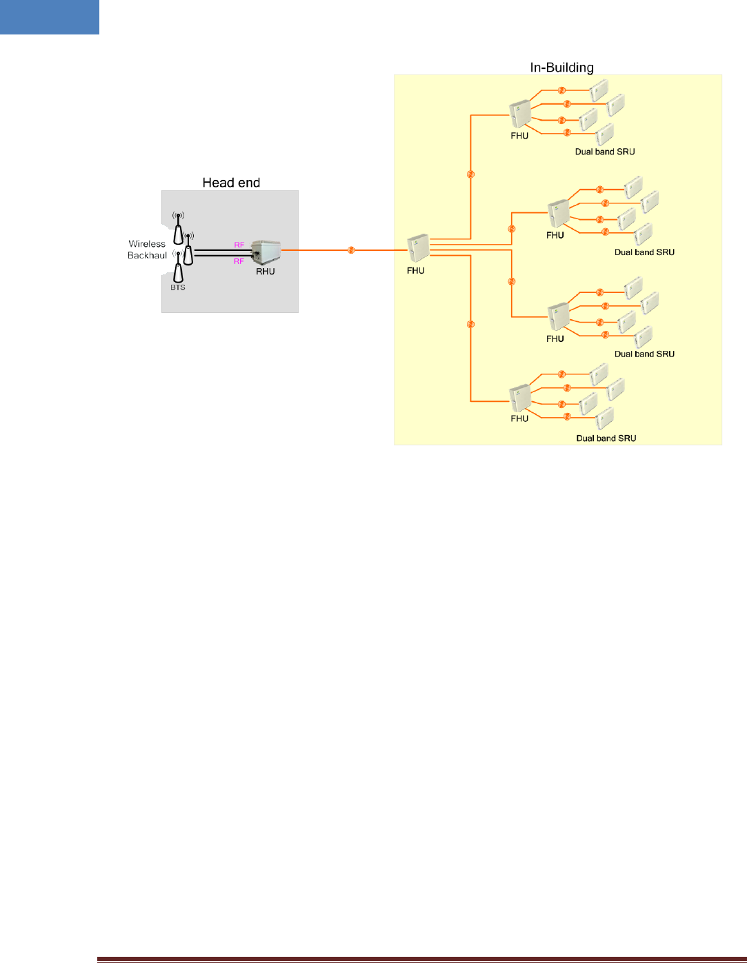
As illustrated in Figure 1-1, Hybrid DAS network is comprised of RHU, FHU and SRU. Each RHU can
support up to 16 pair of SRU’s that can cover up to 500Ksf2 indoor space.
Intelibs, Inc Proprietary and Confidential Page 6
6
Figure 1-1 RHU-FHU-SRU/RU network diagram
Intelibs, Inc Proprietary and Confidential Page 7
7
2 Product Description
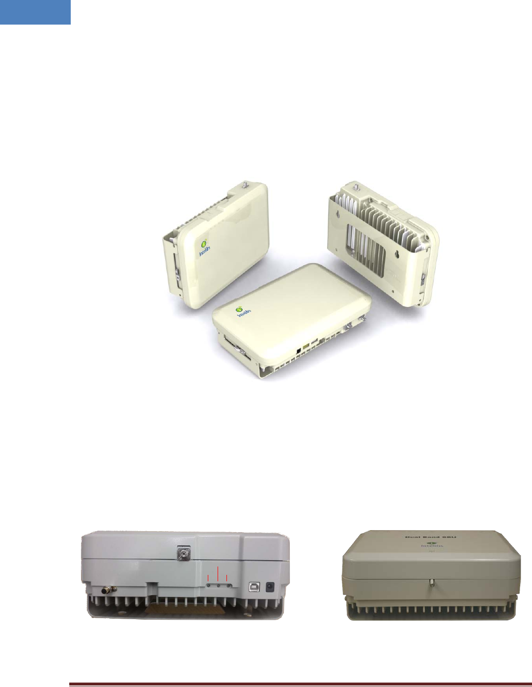
As shown in Figure 2-1, SRU is a compact platform with the natural heat convection. As unified form
factor, SRU services multiple technologies on a single platform with Dual band operating frequencies. It
can be mounted on the wall, ceiling or 19” rack. Variety of the service antenna can be used from short
monopole antenna (e.g. rubber ducky antenna) to indoor multi-band ceiling Omni antenna (or panel
antenna).
Figure 2-1 SRU system
2.1 External interface ports and Status Indicators
SRU has all interface connections at topside of the enclosure, which includes optic, antennas, power,
and maintenance port. Figure 2-2 shows the front panel of SRU.
Figure 2-2 Top and bottom side SRU
Power
Debug
Power
Run
Alarm
Optic
LTE
ANT

Intelibs, Inc Proprietary and Confidential Page 8
8
Table 2-1 Interface ports
Port
Connector type
Position
Description
Power DC Power Jack Top 12V DC inlet, AC/DC converter or PoE adapter
Debug USB Top Serial interface for GUI and debugging
Optic FC/APC Top Optic fiber connection with FHU
LTE SMA-Female Top LTE Uplink/Downlink RF signal interface
ANT SMA-Female Bottom Omni ANT connection
Table 2-2 Status indicator LEDs
Name
Normal state
Abnormal state
Description
Power
Green
Off
Power injection status
RUN
Green/Blinking
Off
CPU working status
Alarm
Green
RED
Major Alarm status
Intelibs, Inc Proprietary and Confidential Page 9
9
2.2 Modules
SRU is comprised of several internal modules as follows;
• Optic module Performs E/O (or O/E) conversion for FWD and RVS signals.
• MCU Board Monitors the status of modules in SRU and controls the configurable parameters of the
SRU modules.
• Quadruplexer cavity filter passes FWD and RVS path PCS/Cellular frequency bands.
• RF Transceiver controls the gain of FWD path of PCS/Cellular frequency bands.
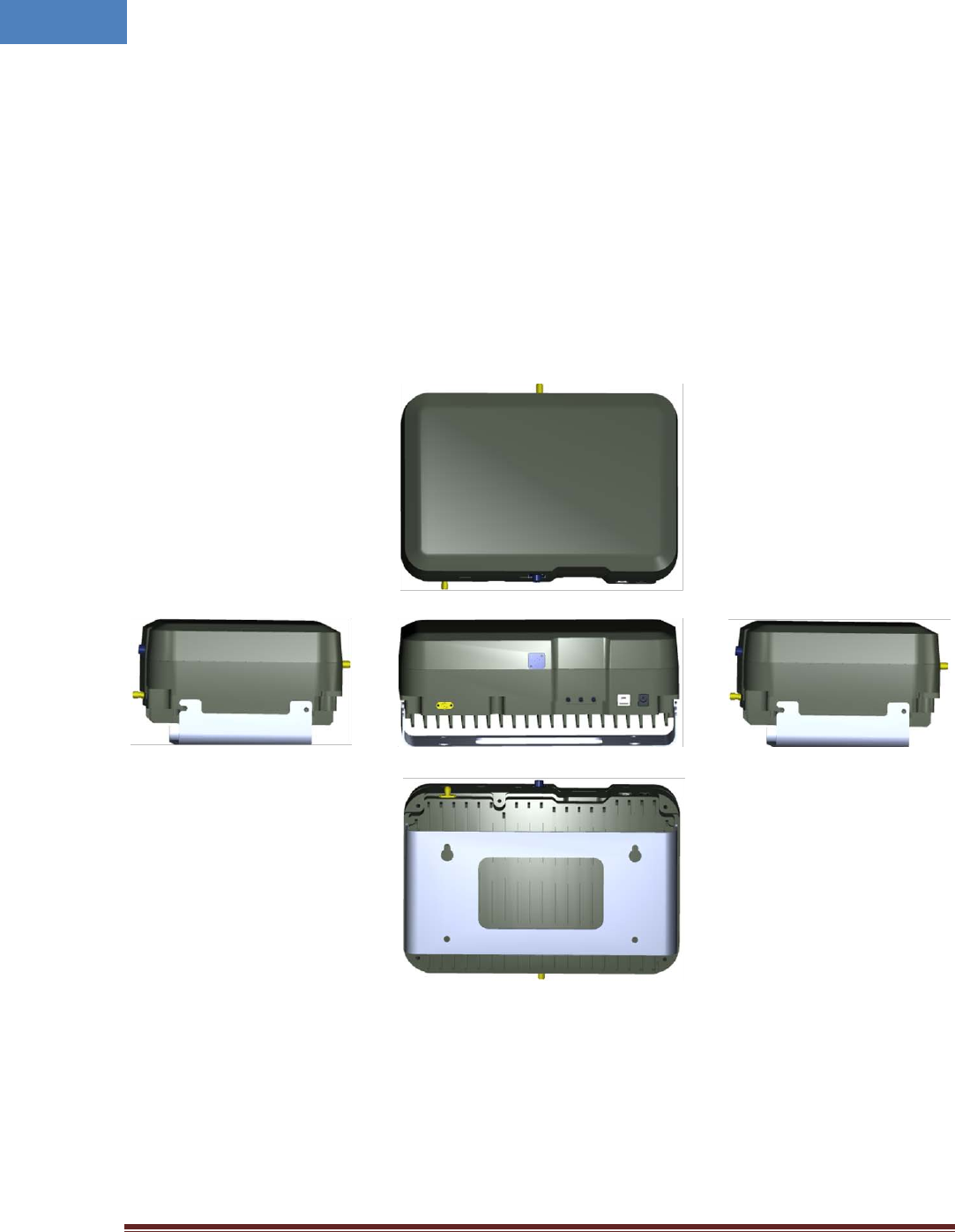
2.3 Mechanical Drawing
Figure 2-3 Exterior in 3-dimension
Intelibs, Inc Proprietary and Confidential Page 10
10
2.4 Technical Specifications
2.4.1 General specifications
Table 2-3 General Specifications
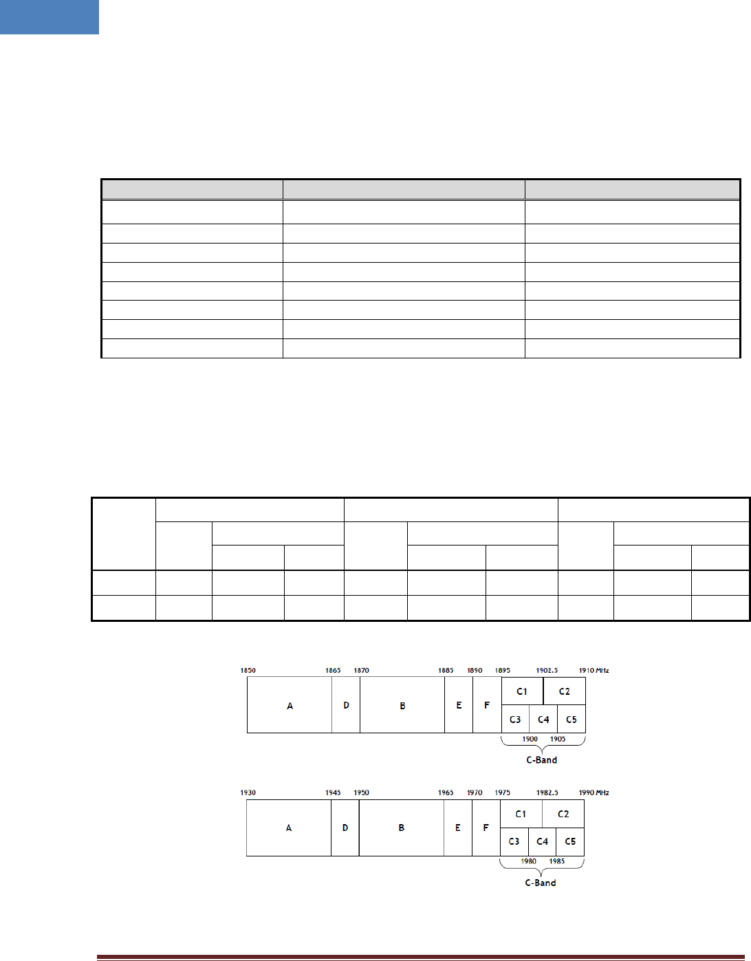
2.4.2 Frequency allocation
2.4.2.1 1900 MHz band
Table 2-4 First and last channel center frequency information of 1900MHz band
Band
Edge
GSM 1900 WCDMA 1900 CDMA 1900
CH No.
CH Center freq. (MHz)
CH No.
CH Center freq. (MHz)
CH No.
CH Center freq. (MHz)
Down Link Up Link Down Link Up Link Down Link Up Link
First CH 512 1930.2 1850.2 9662 1932.4 1852.4 25 1931.25 1851.25
Last CH 810 1989.8 1909.8 9938 1987.6 1907.6 1175 1988.75 1908.75
Figure 2-4 Frequency band allocation of 1900 MHz band
Specification
Values
Remarks
Dimensions 89(H) x 175.8(W) x 263.8(D) mm without holder bracket
Weight
4.6 Kg
ANT and RF connector
SMA-type Female
Optic port
FC/APC type
GUI port
USB B-type
Input Supply Voltage
12V DC
PoE adapter/splitter
Operating Temperature
-20 ~ +50 °C
Humidity
5 ~ 80% Relatively
Intelibs, Inc Proprietary and Confidential Page 11
11
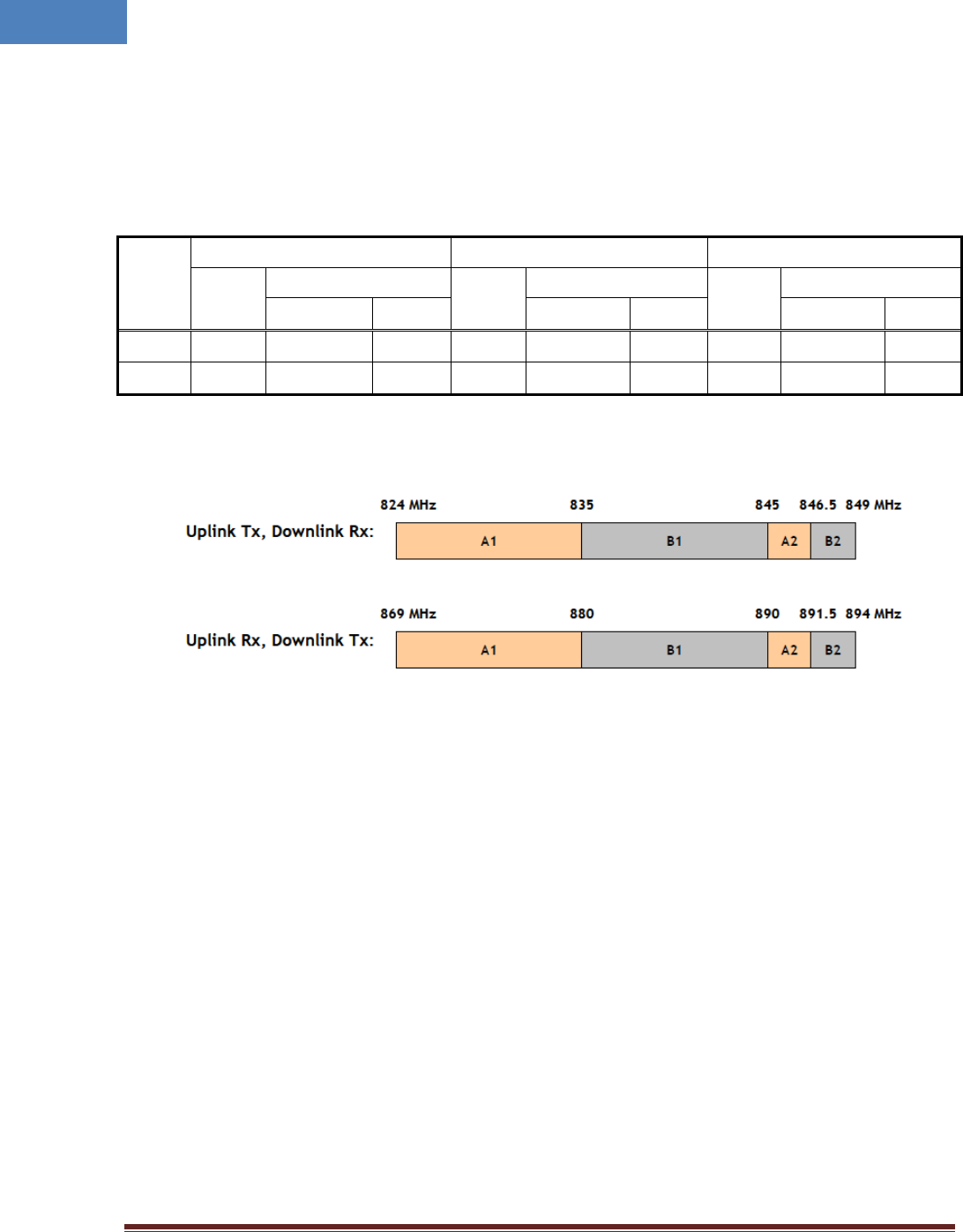
2.4.2.2 850 MHz band
Table 2-5 First and last channel center frequency information of 850MHz band
Band
Edge
GSM 850 WCDMA 850 CDMA 850
CH No.
CH Center freq. (MHz)
CH No.
CH Center freq. (MHz)
CH No.
CH Center freq. (MHz)
Down Link Up Link Down Link Up Link Down Link Up Link
First CH 128 869.2 824.2 139 871.4 826.4 1013 869.7 824.7
Last CH 251 893.8 848.8 240 891.6 846.6 777 893.31 848.31
Figure 2-5 Frequency allocation of 850 MHz band

Intelibs, Inc Proprietary and Confidential Page 12
12
2.4.3 RF specifications
Table 2-6 Dual band specifications
2.4.4 Power Specifications
Table 2-7 Power specifications
Item
Specification
Rated Input Voltage
12 V DC
Permissible range
Tolerance ±10%
Power consumption 30 W, maximum
27 W, typical
Item
Specification
Remarks
Downlink Frequency
869 ~ 894 MHz, 1930 ~ 1990 MHz
Uplink Frequency 824 ~ 849 MHz, 1850 ~ 1910 MHz
Operating Bandwidth Cellular: 25MHz BW
PCS: 60MHz BW
DL Output Power
+26dBm/composite @ANT Port
Dual Band Output Power
Optical wavelength
SRU: DL 1310/UL 1550nm
WDM included
Optic Module Gain
0dB w/ passive device loss
Optic Module Gain FHU ~ SRU
Available optical fiber loss 2dBo (2Km) max. Including connector loss.
Gain ripple over each band
2 dB Peak to Peak
Gain flatness over 25MHz BW
Gain flatness over Dual Band
+/- 2dB(4dBp-p)
Gain flatness of 850/1900MHz
Attenuator Control Range
0 ~ 30dB
Optic loss Compensation
Gain Control Step Size 1 dB ±0.7 dB tolerance at 0 ~ 25dB
Input VSWR 1.5: 1 Max. All of RF Port
Frequency Stability ±0.01 ppm
System Delay 500nsec max.
EVM 5% max.
Rho
0.998 min.
Spurious Emissions
Comply to 3GPP, 3GPP2 and FCC
Rx Noise Figure
5 dB @UL Gain 40dB
@ Room temperature
Rx max. input level
-40dBm
CW -30dBm can be receivable
System Gain
DL 45~47dB/UL 50~52dB
Gain ±2dB @-20~50°C

Intelibs, Inc Proprietary and Confidential Page 13
13
2.5 Installation
2.5.1 Installation Requirements
Before and during installation, the following should be carefully verified in order to avoid any
problem:
• Faulty Cabling/Connectors: Fiber cable and connectors must be verified prior to plugging
into the SRU
• Dirty Connectors and ports
• Faulty Small Remote Unite (SRU) components
• RF source equipment issue
• External RF Interface problem such as antenna port
• Wrong or Improper Ethernet cable for POE input
The following guidelines are required when the Headend unit is installed on the 19” rack:
• Locate the equipment with the space for the sufficient airflow to prevent build-up from
the overheating. Do not compromise the amount of airflow required for safe operation of
the equipment.
• Verify the power connection and Fiber cables prior to turning on the systems.
WARNING: Equipment loading must be verified prior to mounting the equipment on the wall or 19” rack.
2.5.1.1 General Safety Precautions
The following precautions apply to the SRU:
• The units have no user-serviceable parts. Faulty or failed units are fully replaceable through
Intelibs.
• When the Fiber cable is connected to the equipment, the connectors must be free from the dust
and connected according to the cable manufacturer’s instructions. (WARNING: For the safety,
DO NOT conduct eye-contact at the connector ends of the fibers or the port of the FHU and SRU
unless equipped with protection goggle. Invisible infrared radiation may be present at the front
panel of the RHU, FHU and SRU. Do not remove the fiber port dust caps unless the port is going
to be used. Do not stare directly into a fiber port.)
• When the service antenna is connected to the SRU, SMA connector must be firmly tightened.
(Caution: Do NOT over tighten the connector.)
• The PoE Ethernet cable should be run with the maximum no more than 300 feet distance. It is
only for in-building use only.
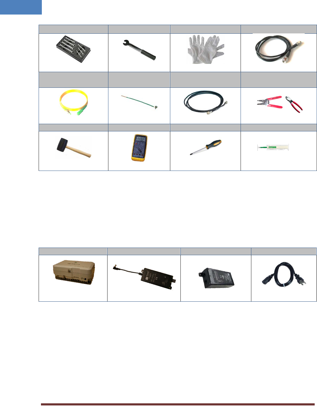
2.5.2 Installation Tools
Table 2-8 Installation tools
Intelibs, Inc Proprietary and Confidential Page 14
14
Torque Wrench Torque Wrench ESD Gloves 4ea of 5m SMA cable
FC/APC-SC/APC
Optic Fiber, 10m Ground wire line 2ea of ANT RF Cable Wire Stripper & Cutter
Rubber Mallet
Digital Multi-meter
Screw Driver
Optic connector cleaner
2.5.3 Item Check List
Check that all the following items have been included with the box delivered. If anything is missing,
please contact Intelibs.
Table 2-9 Item check list
SRU
PoE splitter
PoE adapter
AC power cable
SRU equipment with
bracket: 1 ea
PoE splitter: 1 ea
PoE adapter: 1 ea
AC power cable: 1 ea
Intelibs, Inc Proprietary and Confidential Page 15
15
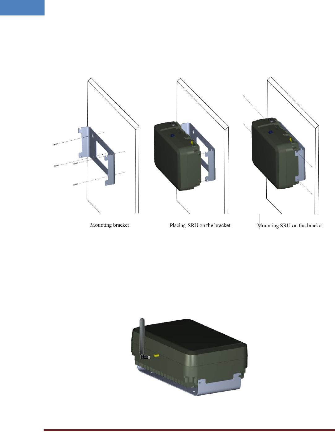
2.5.4 Wall Mounting
SRU supports wall mount. The following diagrams illustrate the methods for mounting SRU in a typical
wall. The brackets for wall mount are provided with SRU system.
Figure 2-6 Wall mounting
2.5.5 Antenna
SRU uses various antennas depends on its application and environment. SRU provides one antenna port
“ANT” at the rear side of the system. Figure 2-9 shows antenna connection with swivel blade antenna.
Figure 2-7 Antenna connection
Intelibs, Inc Proprietary and Confidential Page 16
16
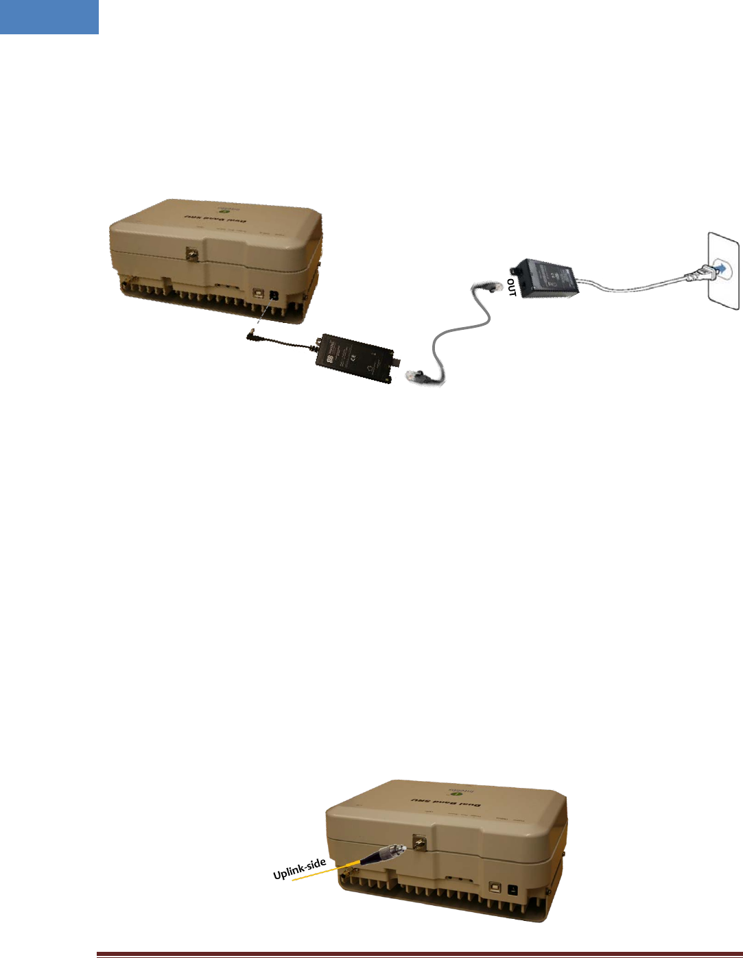
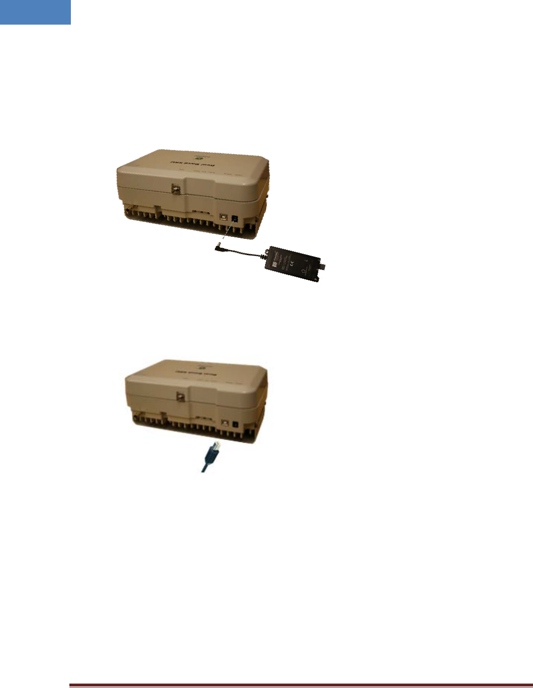
2.5.6 Power cable
SRU uses 12V DC power, and DC power adapter/splitter set using PoE (Power over Ethernet) technology
are provided with the system. The PoE adapter converts AC input to 48V DC, and delivers DC power via
UTP5 Ethernet cable up to 330 feet. The PoE splitter receives 48V DC power via UTP5 Ethernet cable,
and converts 48V to 12V DC. The power connection diagram is described in Figure 2-8.
Figure 2-8 Power connection
Power connection sequence is as follows:
① Connects UPT5 cable to “OUT” port of PoE adapter.
② Connects UTP5 cable to “IN” port of PoE splitter.
③ Connects one end of power cable to PoE adapter’s AC inlet, and the other side of power cable to
AC outlet.
④ Verify the LED status on PoE splitter and adapter
⑤ Connects DC output connector to “Power” port of SRU.
2.5.7 Optic cable
SRU provides one optic port for uplink, “Optic” port, and optic connector type is FC-APC (Angle Physical
Type). While connecting the optic cable, align the FC type connector at latch and hole position, then plug
in and rotate clockwise tightly.
PoE adapter
PoE splitter
UTP5 cable
(up to 330 feet)
Power
Intelibs, Inc Proprietary and Confidential Page 17
17
Figure 2-9 Optic cable connection
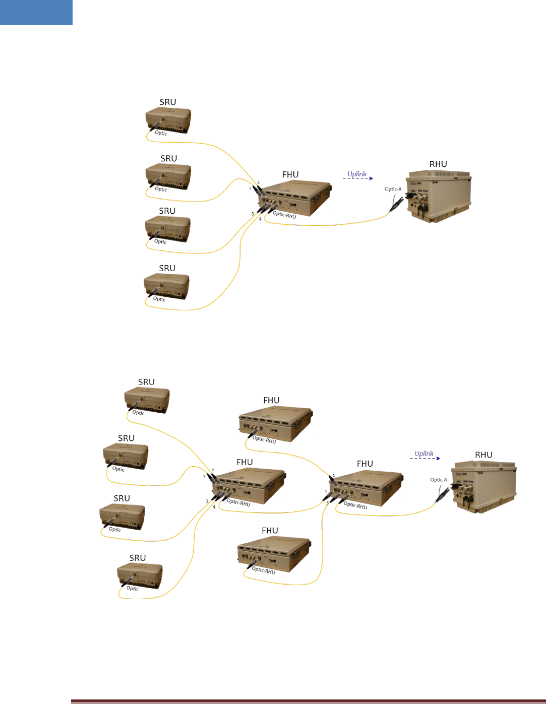
Figure 2-10 and 2-11 shows optic connection of RHU-FHU-SRU equipment.
Figure 2-10 Optic cabling when cascading DAS systems with one FHU
Figure 2-11 Optic cabling when cascading DAS systems with two-stage FHU
Please refer to the SRU Installation Guide for details.
Intelibs, Inc Proprietary and Confidential Page 18
18
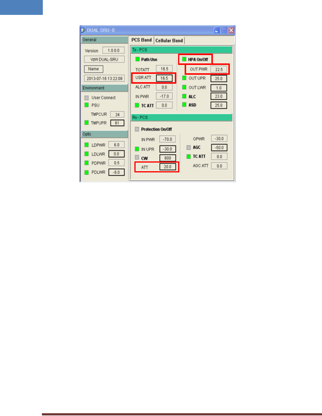
2.6 SRU power setting
2.6.1 Down Link power setting
1. Connect the power cable to SRU
2. Connect USB cable to manage SRU through Laptop.
3. Execute application program and open GUI screen of SRU
PoE splitter
Power
Intelibs, Inc Proprietary and Confidential Page 19
19
4. Decrease the DL “USER ATT(①)” to 30dB(Minimum gain) and verify that antenna is
connected at antenna port of SRU properly.
5. Press the “HPA On/Off(②)” button to turn HPA on
6. Monitor the output power level from “ OUT PWR(③)” parameter and tune up “USR ATT(①)”
to set the proper output power level of SRU.
2.6.2 Up Link power setting
1. Use the “ATT(④)” to control Uplink gain.
2. Uplink gain is very important parameter because uplink is connected to RF source of BTS. If
you have wrong uplink gain set BTS receiver sensitivity may be degraded by SRU uplink gain.
3. Try to minimize uplink gain with mobile Tx power.
2.7 Configuration and Maintenance
SRU can be configured in three ways via remote internet connection or local serial port connection.
• SNMPv3 interface through the internet
• Web interface through the internet
• Local management interface through the internet, serial connection, and Bluetooth
Master Unit is a remote management system that provides SNMP v3 and Web interface, and maintains
all functions of optical DAS system including configurations, monitoring, and real time alarm reporting.
③
①
②
④
Intelibs, Inc Proprietary and Confidential Page 20
20
LMT (Local Management Terminal) is local management interface through IP network, serial interface,
and Bluetooth.
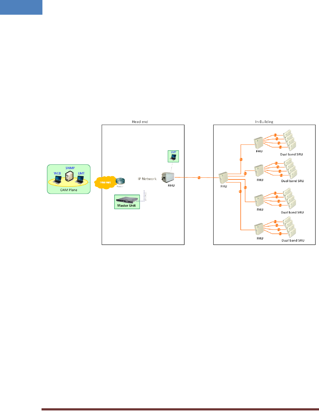
The configuration and maintenance for SRU is performed by accessing RHU system through any
interfaces provided by RHU.
Figure below describes a typical DAS management system network and the entities.
Figure 2-12 DAS management network and entities
Intelibs, Inc Proprietary and Confidential Page 21
21
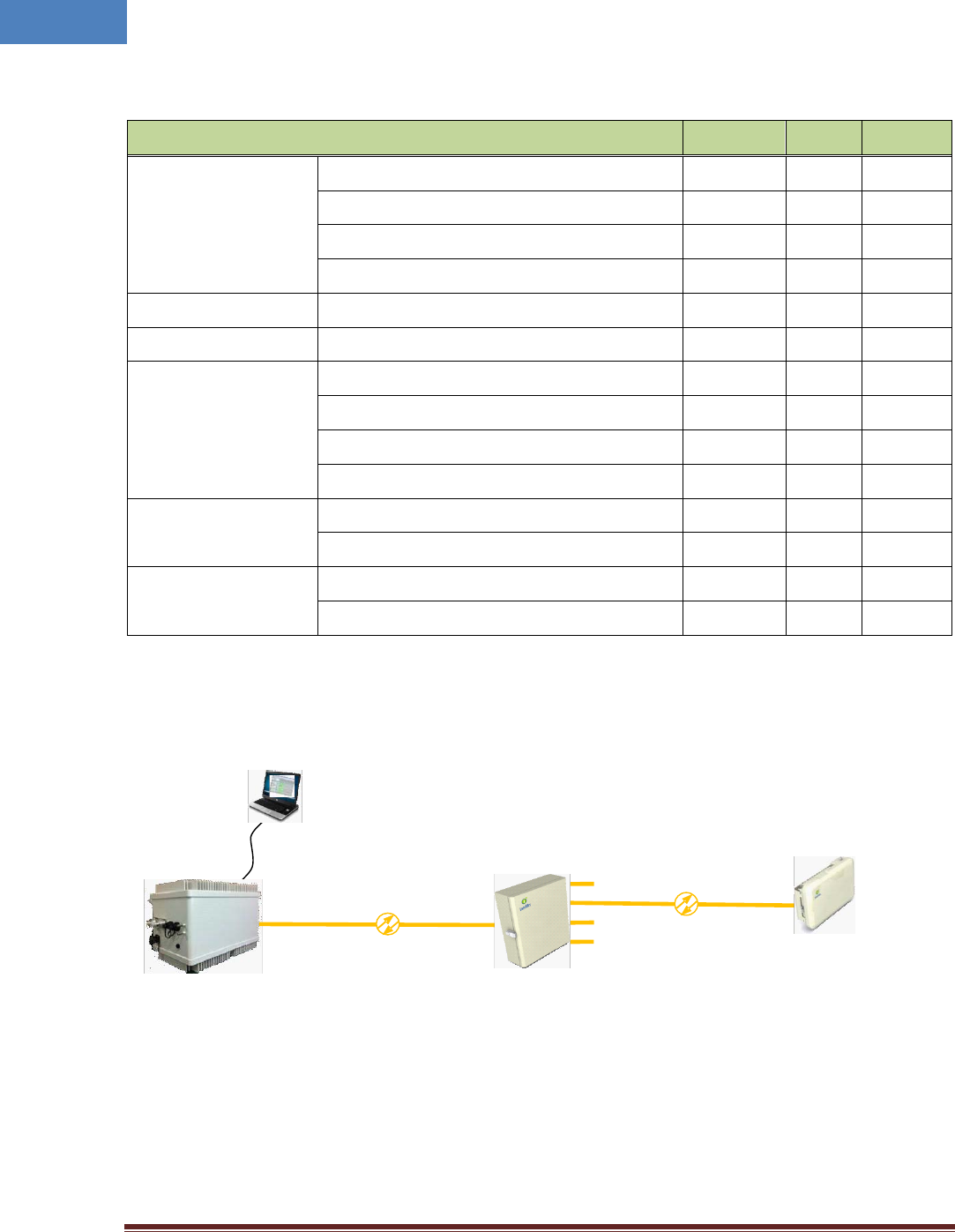
Table 2-10 DAS management entities and their functions
Functions SNMPv3 Web LMT
On-site Installation
Serial interface o
IP address assignment o
ID assignment (for Remote Unit) o
System Password o
System Registration System Registration/Unregister o
Site/Location setting DAS system’s site and location information o
Remote/Local
management
Capture and restore the configuration o
Parameters settings and retrieval o o o
F/W upgrade o o
Alarms o o o
Alarms
Alarm history o
Current Alarm o o o
User management
Creation & Deletion of users o o
Password management o o o
Figure 2-13 RHU/FHU/SRU network
Figure 2-13 is an example of DAS network using LMT to configure DAS system. Followings sections
describes how to configure and manage FHU system using LMT via Bluetooth connection or using Web
Interface via Internet.
Figure 2-14 Bluetooth connection
FHU
(ID=0)
RHU
RS
-
232/LAN
Dual Band SRU
(
ID=1)
LMT
1
2
3
4
Intelibs, Inc Proprietary and Confidential Page 22
22
2.7.1.1 Configuring FHU/SRU
If one of Bluetooth or Ethernet connection has been established, LMT is ready to start. Launch the Local
Management application by clicking the icon “Cherry” and follows the steps below.
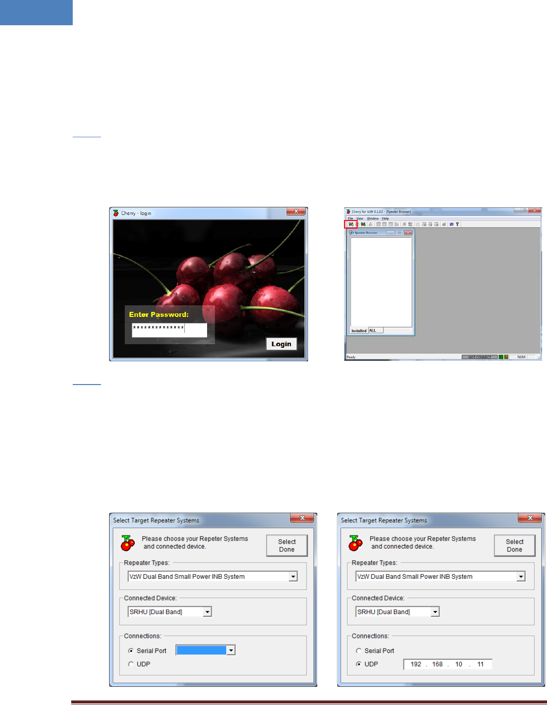
Step 1
• Launch the application “Cherry”.
• Enter the password, click “Login”.
• Click “Connect” icon on the left top corner of window.
Step 2
• Select the connection parameters as follows:
- Repeater Types: VzW Dual Band Small Power INB System
- Connected Device: SRHU [Dual Band]
- Connections
o Serial Port: The port number established via Bluetooth or
o UDP: IP address for the Ethernet interface
Intelibs, Inc Proprietary and Confidential Page 23
23
• Click “Select Done” button.
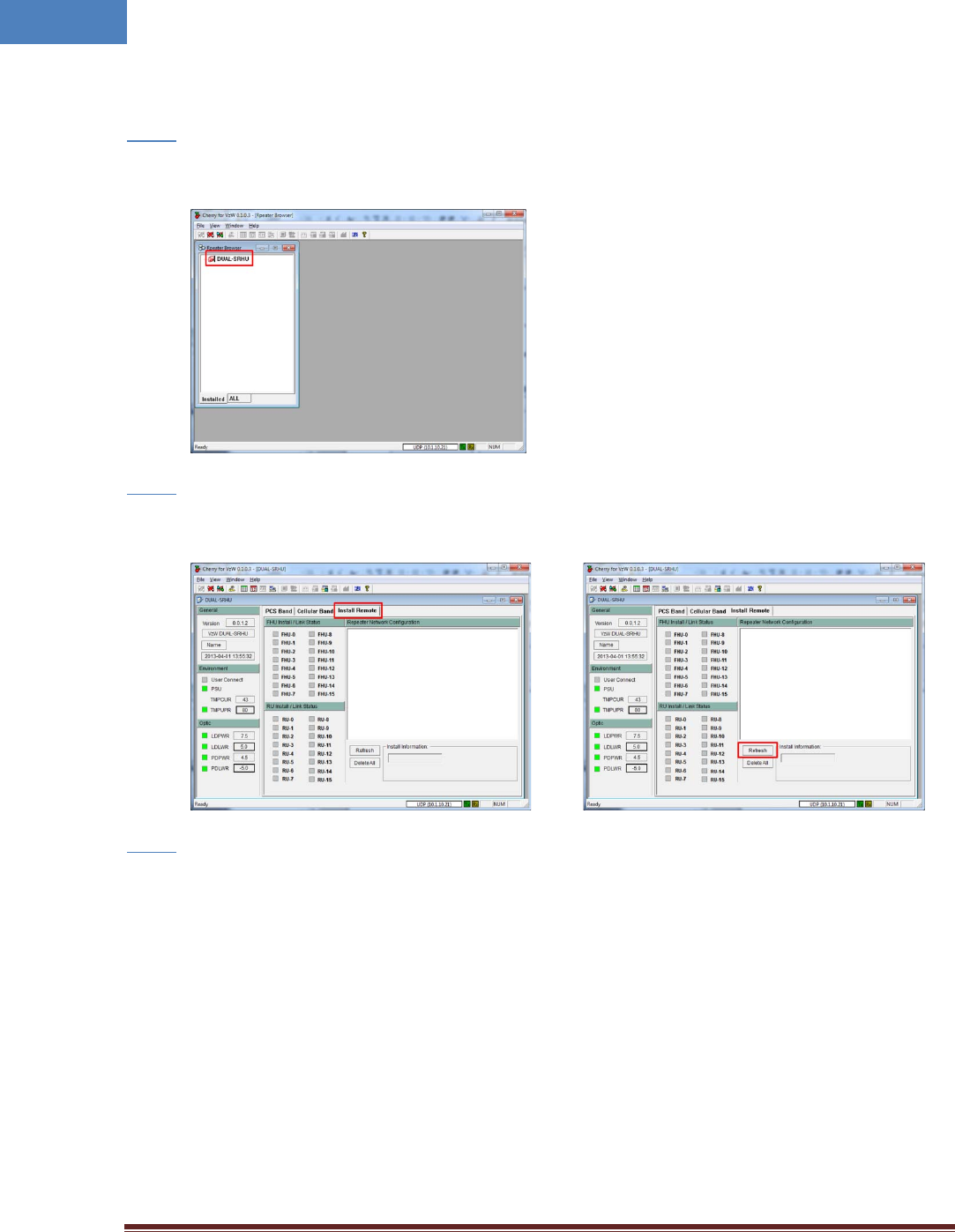
Step 3
• If “Repeater Browser” window appears, click DUAL-SRHU system.
Step 4
• Select “Install Remote” tab to install FHU and SRU, then click “Refresh” button.
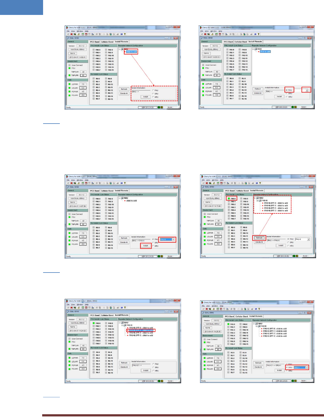
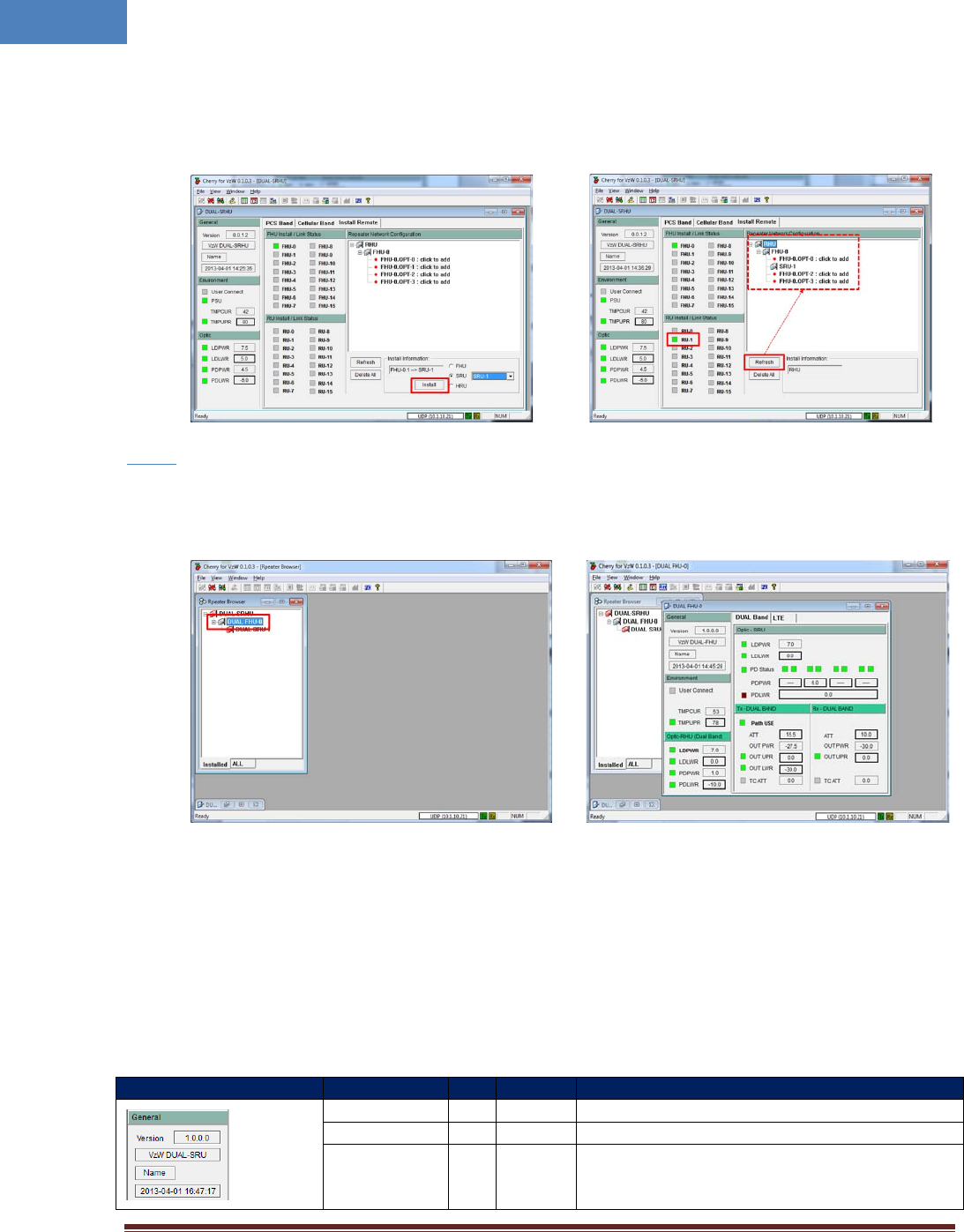
Step 5
• At “Repeater Network Configuration” window, click “click to add” text.
• In the “Install Information” select “FHU”.
• Select FHU ID from the FHU drop down list. FHU’s ID is provided by manufacturer.
Intelibs, Inc Proprietary and Confidential Page 24
24
Step 6
• If FHU’s ID is selected, click “Install” button at “Install Information”.
• After Install, click “Refresh” button to display installed equipment.
• If FHU is installed properly, at “FHU Install / Link Status“ panel a check box on the left side of
FHU’s ID turns to GREEN, otherwise it turns to RED.
Step 7
• Click “click to add” text on FHU’s port that SRU attached, then select “SRU” and click drop-down
box to select SRU’s ID. SRU’s ID is provided by manufacturer.
•
Step 8
Intelibs, Inc Proprietary and Confidential Page 25
25
• If SRU’s ID is chosen, then press “Install” button. After Install, press “Refresh”.
• If SRU is installed properly, a small box on the left side of SRU’s ID turns to GREEN, otherwise it
turns to RED.
Step 9
• At “Repeater Browser” window, click the DAS system to be managed, then the selected DAS
system’s control window will pop up.
If connection is established successfully, then all parameters of SRU can be set by LMT terminal, and all
status information can be reported to LMT. SRU’s status and parameters controllable by LMT are
described in Table 2-11, 2-12, and 2-13.
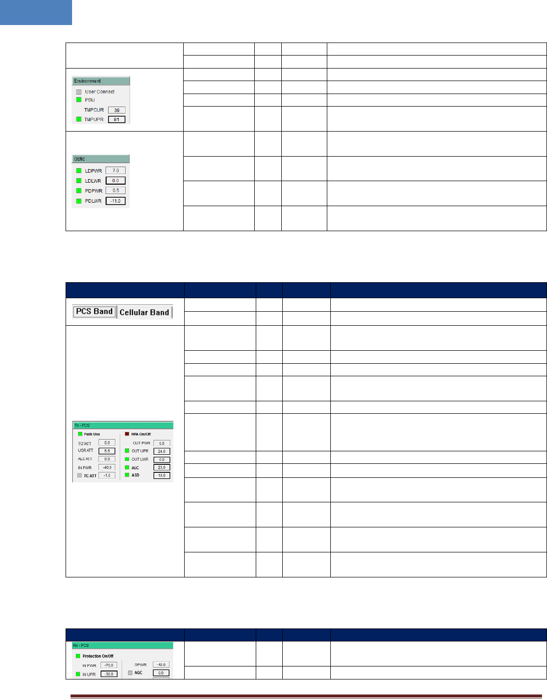
Table 2-11 General/Environment/Optic
Status group
Parameters
LED
Settable
Description
Version Firmware Version of the DAS system
DAS Type
The type of the DAS system
Name
√
Set following information of the DAS
- Name
- Model Number
Intelibs, Inc Proprietary and Confidential Page 26
26
- Serial Number
Time/UpTime Current time or Up-time
User Connect √ Connection status with the DAS
PSU
√
Status of Power Supply Unit
TMPCUR Current chassis temperature of the DAS system
TMPUPR √ √
Set temperature upper limit, and display its value
and alarm status.
LDPWR √ Current output power of LD (Laser Diode) of optic
module connected to SRU.
LDLWR √ √ Set the lower limit of output power of LD, and
display its value and alarm status.
PDPWR √ Current input power of PD (Photo Detector) of
optic module connected to SRU.
PDLWR √ √ Set the lower limit of input power of PD, and
display its value and alarm status.
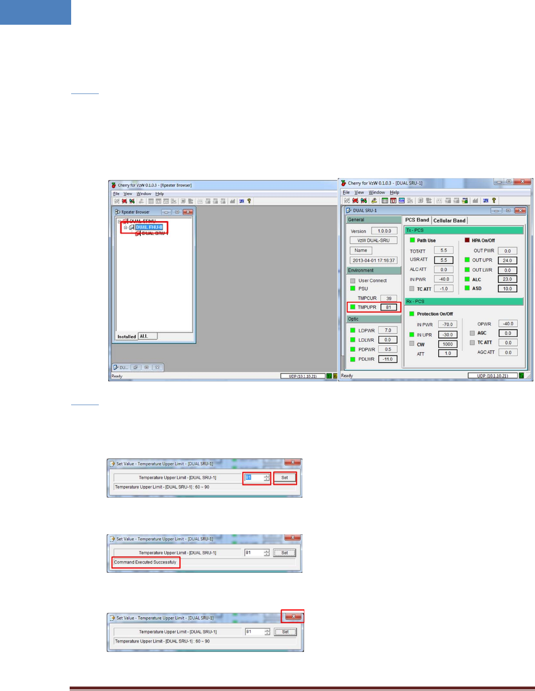
Table 2-12 Tx-PCS/Cellular
Status group Parameters
LED
Clickable Description
PCS Band
Selects PCS channel
Cellular Band
Selects Cellular channel
Path Use √ √ Turning On/Off of usage of the channel, and
display its status
TOTATT
Downlink total attenuation value
USR ATT
√
Set user configurable downlink attenuation value
ALC ATT Downlink ALC (Automatic Level Control)
attenuation value
IN PWR Downlink input power from RHU or FHU
TC ATT √
Displays downlink temperature compensation
attenuation value, and enable/disable downlink
temperature compensation.
HPA On/Off √ √ Enable/disable downlink HPA (High Power Amp).
OUT PWR Downlink output power
OUT UPR √ √ Set upper limit of downlink output power, and
displays its value and alarm status
OUT LWR √ √ Set lower limit of downlink output power, and
displays its value and alarm status
ALC √ √ Set ALC (Automatic Level Control) function’s
activation level, and enable/disable ALC.
ASD √ √ Set ASD (Automatic Shut Down) function’s
activation level, and enable/disable ASD.
Table 2-13 Rx-PCS/Cellular
Status group
Parameters
LED
Clickable
Description
Protection
On/Off √ √ Enable/disable uplink Protection function.
IN PWR
Uplink input power

Intelibs, Inc Proprietary and Confidential Page 27
27
IN UPR √ √ Set upper limit of uplink input power, and displays
its value and alarm status
CW √ √ Enable/disable uplink Pilot, and selects uplink CW
channel.
ATT √ Set uplink attenuation, and displays its value.
OPWR
Uplink output power
AGC √ √ Set AGC (Automatic Gain Control) function’s
activation level, and enable/disable AGC.
TC ATT √ √
Displays uplink temperature compensation
attenuation value, and enable/disable uplink
temperature compensation.
AGC ATT AGC (Automatic Gain Control) attenuation
Intelibs, Inc Proprietary and Confidential Page 28
28
2.7.1.2 Setting the Temperature Upper Limit
Following is one example of LMT operation which sets the upper limit of SRU chassis’ temperature.
Step 1
• At “Repeater Browser” window, click the DAS system to be managed, then the selected DAS
system’s control window will pop up.
• Click the temperature upper limit box which is on the right side of “TMPUPR”. A number in the
box represents current upper limit of chassis’ temperature.
Step 2
• Select TMPUPR value by clicking up/down button or enter temperature upper limit. Then click
“Set” button.
• The result of operation displays at the bottom of the window.
• Click close button on the upper right corner of the window to exit the command window.
Intelibs, Inc Proprietary and Confidential Page 29
29
The small color box on the left side of “TMPUPR” represents current status of upper limit of SRU
chassis’ temperature. If the box is GREEN, operating status is in normal condition. If the box is
RED, “TMPUPR” alarm occurred and remains.
2.7.2 Web interface
Master Unit provides comprehensive management of the Intelibs optical DAS systems via Web GUI.
Master Unit provides following functions for Web clients:
• Hierarchical view of the DAS systems
• Alarms histories
• Current Alarms
• SNMP agent settings
• Site and location information settings
• Web user settings
• Capture and restore the configuration of the DAS systems
• Parameter settings of the DAS systems
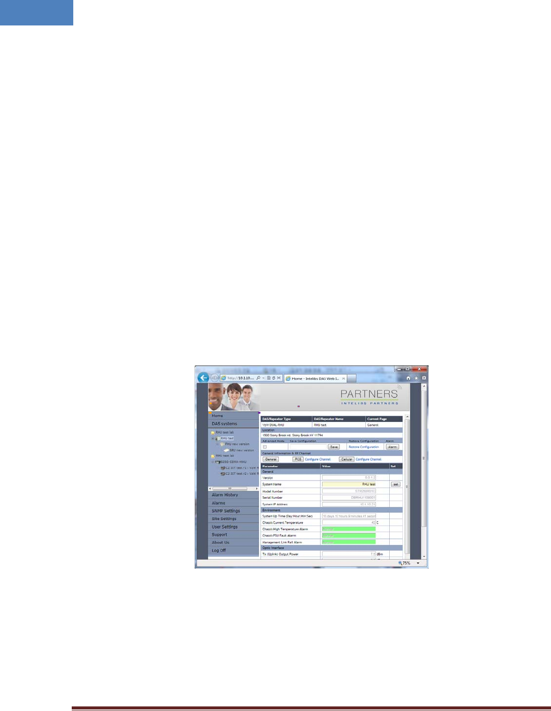
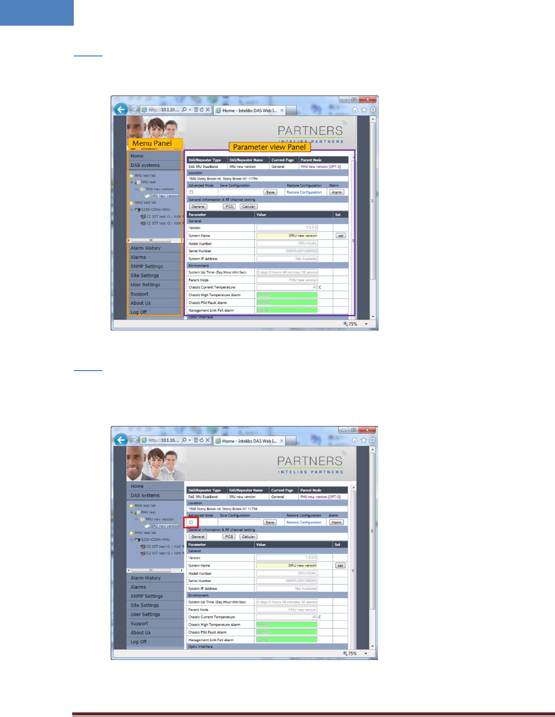
The web GUI is divided into two parts, a menu panel and a Parameter view panel. The menu panel is on
the left side of main window, and the other side is the parameter view panel as shown in Figure 2-15.
Figure 2-15 Web GUI
The menu panel contains following menu functions:
• Home: Introductions of Intelibs, Inc, and brief introduction of GUI usage.
• DAS systems: Hierarchical view of registered DAS systems.
• Alarm history: Alarm log of all registered DAS systems.
Menu Panel Parameter view Panel
Intelibs, Inc Proprietary and Confidential Page 30
30
• Alarms: Current alarms of all registered DAS systems.
• SNMP settings: SNMP environment settings such as trap IP, community, V3 user, etc.
• Site settings: Assign site and location information to each registered Das systems.
• User settings: Add/delete web user and change user’s password
• Support: Intelibs’ support information.
• About us: Redirect to Intelibs’ web page.
• Log Off: Logging off current user’s session.
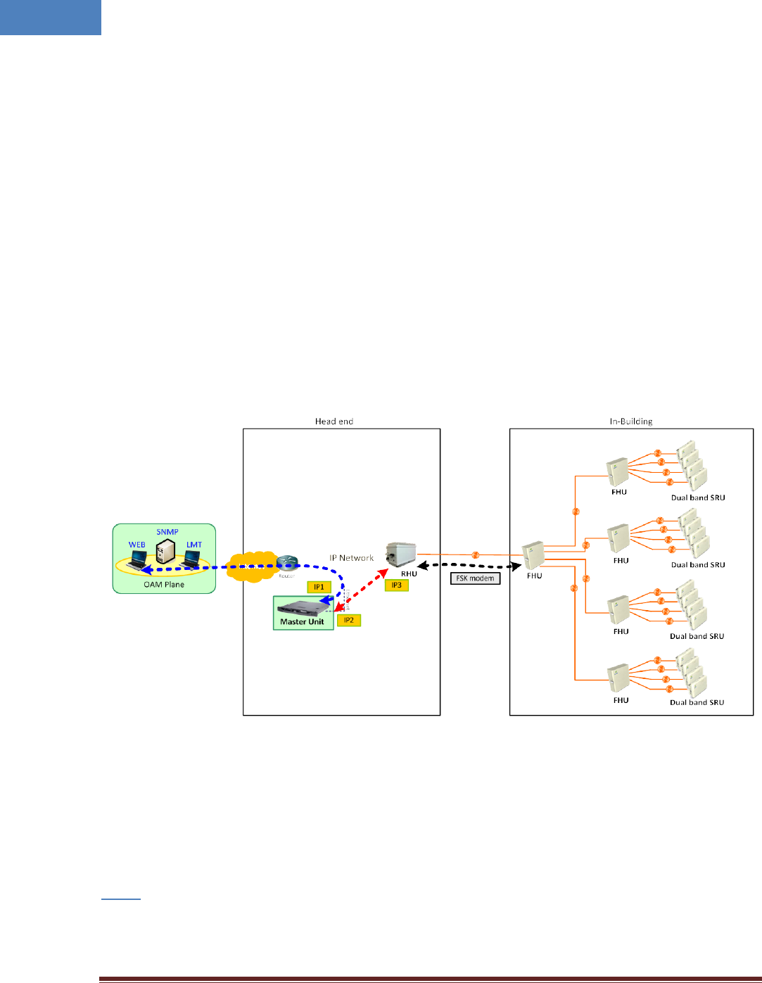
Before using web interface, followings should be assigned and set correctly:
• Master Unit’s IP address
• RHU system’s IP address
• Master Unit’s IP address on RHU system
Figure 2-16 shows web interface flow over IP network.
Figure 2-16 Web interface flow
`
If IP network connection is established successfully, then parameters of SRU can be set by Web browser,
and all status information can be reported to Web browser.
Following is one example of Web operation which sets the upper limit of SRU chassis’ temperature.
Step 1
• Open Web browser such as Internet Explorer or Chrome.
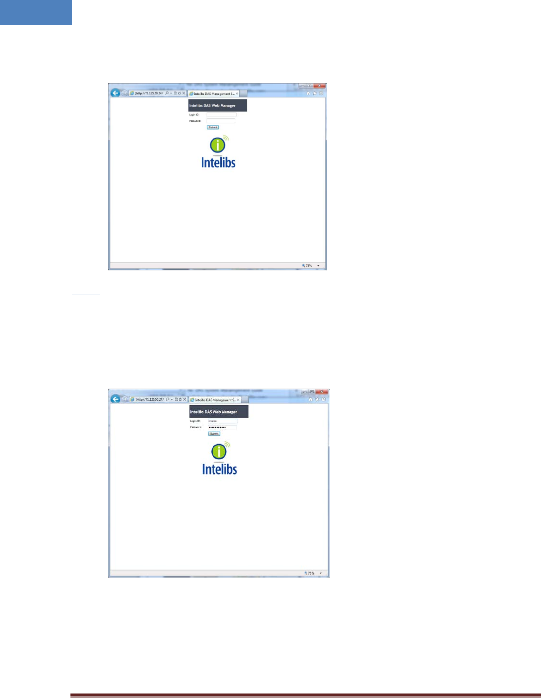
Intelibs, Inc Proprietary and Confidential Page 31
31
• Enter Master Unit’s IP address that is assigned for Web interface. Usually the IP address is global
IP or private IP if web client is on the same network where Master Unit is.
Step 2
• Enter Login ID and Password. (Please contact Intelibs for login ID and password)
The web interface provides two level user access, privileged or not. Privileged users can retrieve
and change the advanced parameters that control the DAS system. For example, “TMPUPR”
parameter is an advanced parameter that requires privileged user login.
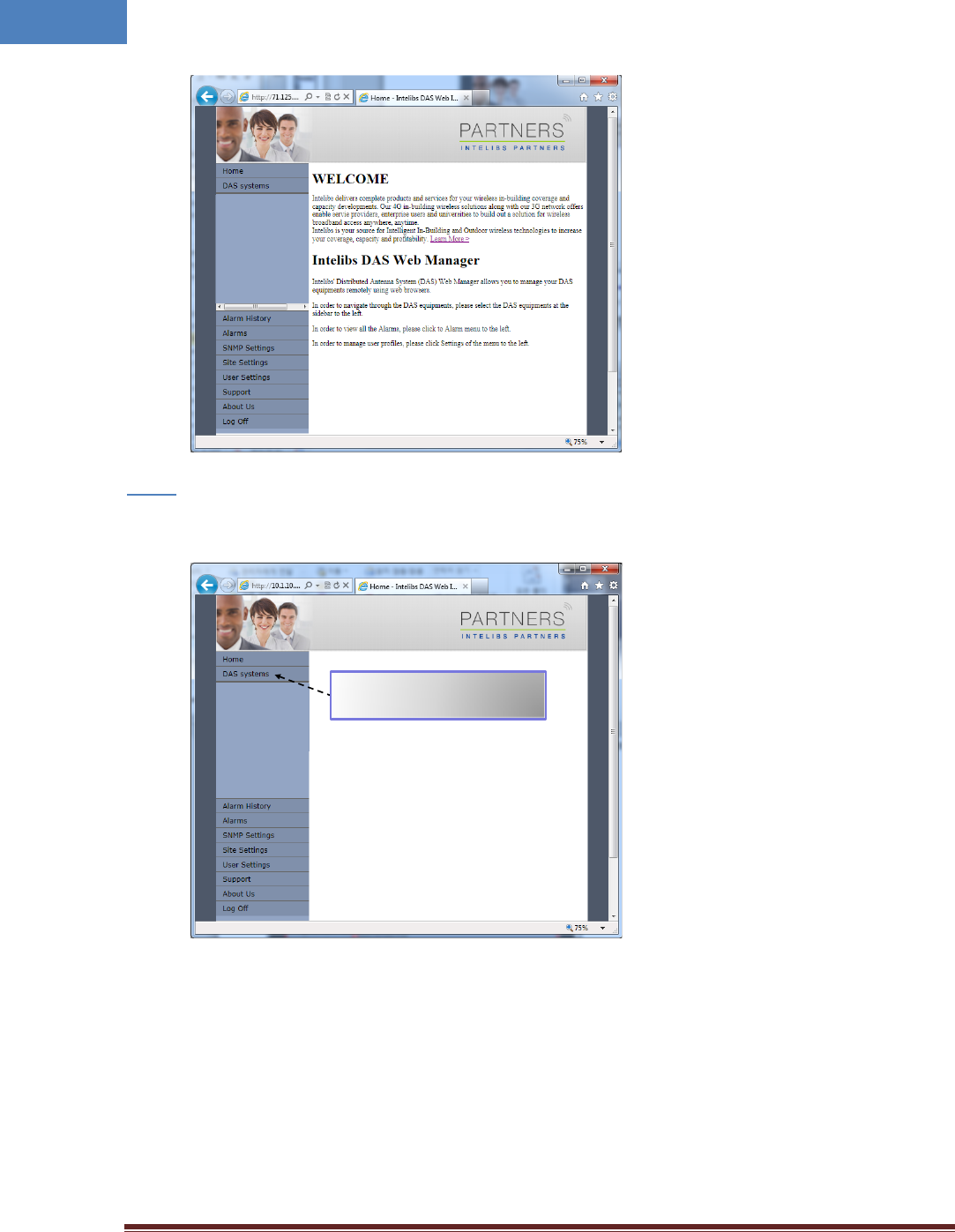
• If ID/PWD matches, Web interface goes to Home page.
Intelibs, Inc Proprietary and Confidential Page 32
32
Step 3
• Click “DAS systems” menu box to see the Hierarchy view of DAS systems.
Clicking this menu box expands
hierarchical tree view of the registered
DAS systems
Intelibs, Inc Proprietary and Confidential Page 33
33
Step 4
• Select a DAS system to control and monitor at the hierarchy view.
Step 5
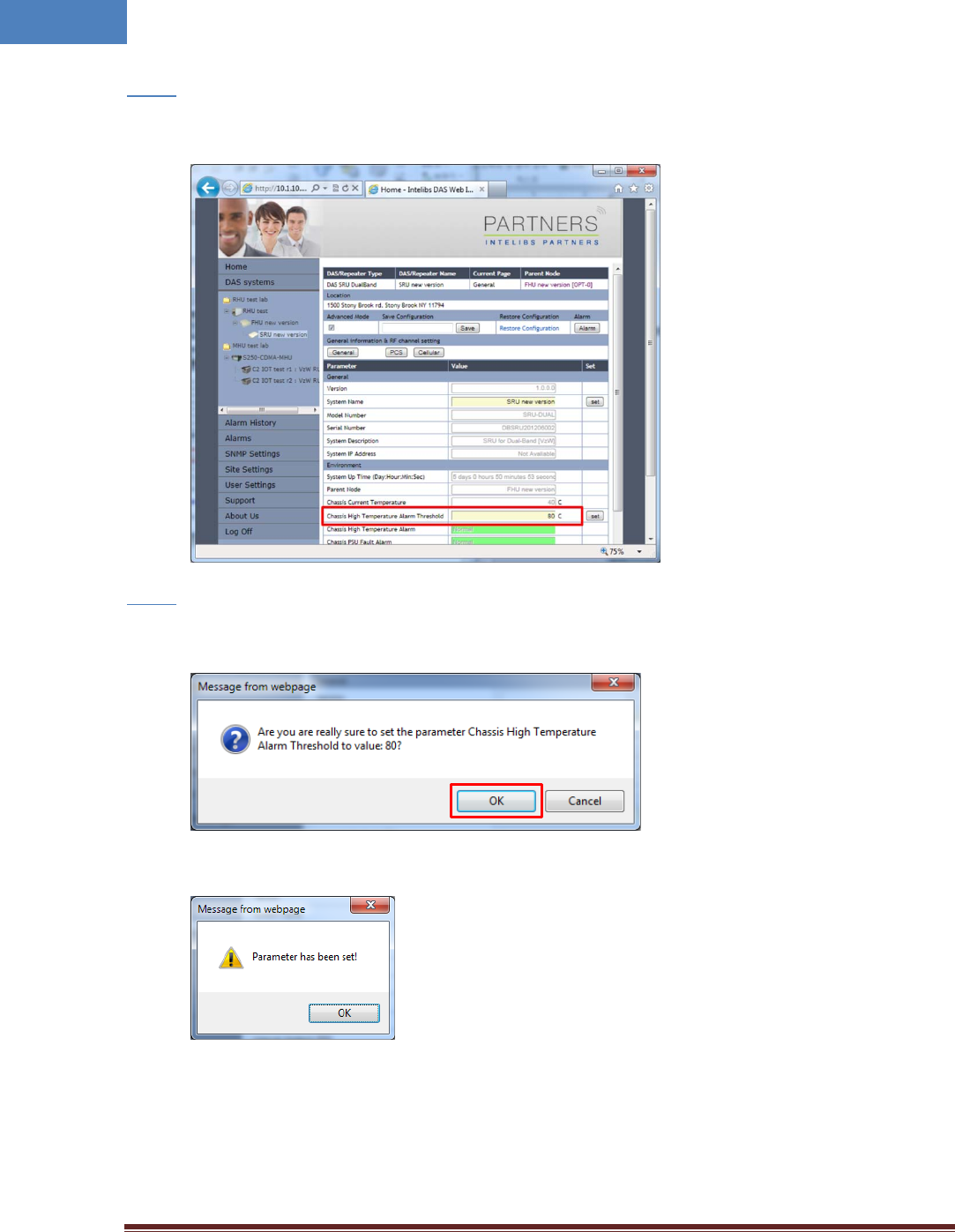
• Select “Advanced Mode” check box to display advanced parameters, for example “Chassis High
Temperature Alarm Threshold” in the parameter view panel.
Intelibs, Inc Proprietary and Confidential Page 34
34
Step 6
• Enter numbers for “Chassis High Temperature Alarm Threshold”. Then click “Set” button.
Step 7
• If confirmation window pops up, click “OK” button to confirm changing the parameter value.
• Then result window will pop up.
The column “Chassis High Temperature Alarm” represents upper limit of SRU chassis’
temperature. If the value box is GREEN, operating status is in normal condition. If the box is
ORANGE, this indicates “TMPUPR” alarm is turned on.
Intelibs, Inc Proprietary and Confidential Page 35
35
3 Appendix I. Ancillary Devices – Antenna, Cable and other Passive
Device
Intelibs does not provide the ancillary device, however the following or equivalent devices are
recommended:
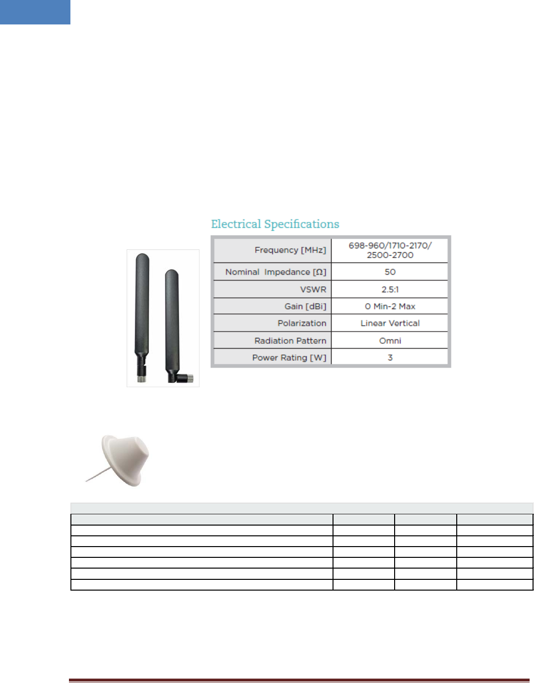
• Recommended Antenna:
o Larson Dipole Antenna
o Commscope
Electrical Specifications
Frequency Band, MHz
698–800
800–960
1710–2700
Gain, dBi
1.5
1.5
5.0
Beamwidth, Horizontal, degrees
360
360
360
VSWR | Return Loss, dB
1.8 | 10.9
1.5 | 14.0
1.5 | 14.0
Input Power per Port, maximum, watts
50
50
50
Polarization
Vertical
Vertical
Vertical
Impedance
50 ohm
50 ohm
50 ohm
• PoE Ethernet Cable and Adaptor:
o CAT6e or equivalent cable is recommended.
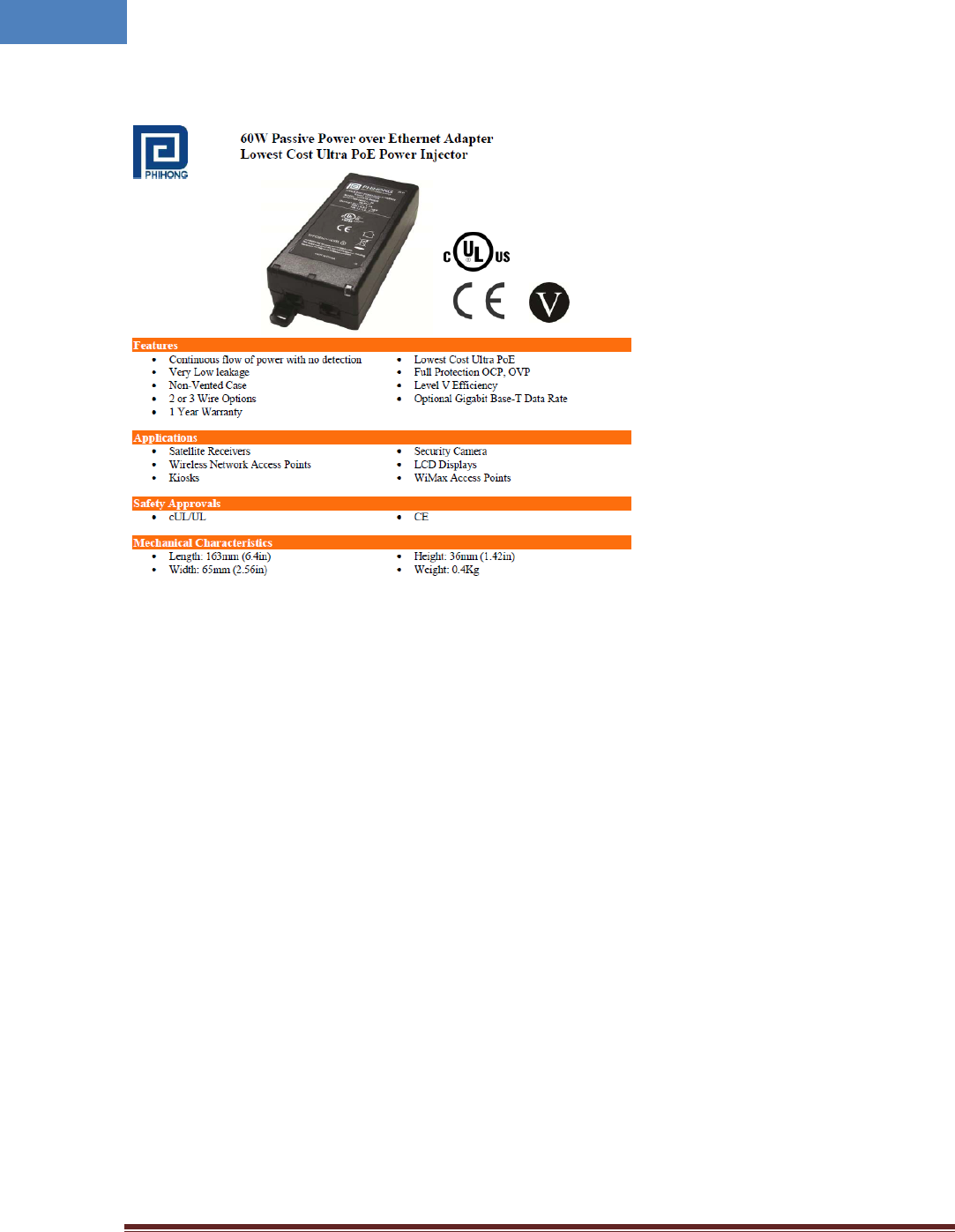
Intelibs, Inc Proprietary and Confidential Page 36
36
Phihong PoE Adaptor (POE61U-560DG-R) and Splitter (POE-45-120-R) or equivalent products
• Coaxial Cable:
o RG142 or equivalent coaxial cables
• Fiber Cable:
o FC/APC optical cable

Intelibs, Inc Proprietary and Confidential Page 37
37
4 Human RF Exposure – Maximum Permissible Exposure Evaluation
The recent FCC developed guideline for evaluation of the human exposure to the RF emissions. The
maximum permission Exposure (MPE) for power density of the transmitter operating RF ranges between
300 KHz and 100 GHz. As the Intelibs SRU belongs to the fixed equipment, Analysis has been conducted
to evaluate the MPE from the distance greater than 20 Cm as the fixed equipment required.
Antenna gain is restricted to 1.5W ERP (2.49 W EIRP) in order to satisfy RF exposure compliance
requirements. If higher than 1.5W ERP, routing MPE evaluation is needed. The antenna should be
installed to provide at least 20 cm from all persons to satisfy MPE requirements of FCC Part 2, 2, 1091.
SRU transmits far below that FCC power density restricts. FCC defines power output limits at 20 cm
distance for various frequency ranges:
• Over 300 MHz to 1.5 GHz the limit is determined by frequency /1500
• Above 1.5 GHz the limit is 1 mW/cm^2
The basic equation for determining power density is:
S = PG/4(pie)R^2
Were S is power density, which is mW/Cm^2
PG, the transmitted power from the antenna indentified as EIRP (Equivalent Isotropically Radiated
Power)
R is the distance of interest from the antenna.
Typical Installation Example:
As the typical height of a floor is assumed as 10 foot high, an average person is assumed 6 foot high, the
distance from antenna to body is 4 feet (112 cm).
For PCS 1900 band, the maximum power output per carrier is assumed 23 dBm. With the assumption of
5 dBi antenna is used, PG in the equation is equal to 28 dBm EIRP.
Using S = PG/4pieR^2
S = 0.63/(4*3.14)*112^2 = 4μW
Also worst case with the assumption of minimum distance of 20 cm according to FCC regulation:
S = 0.63/(4*3.14)*20^2 = 0.1mW

Intelibs, Inc Proprietary and Confidential Page 38
38
Limited Warranty
Intelibs, Inc (“Intelibs”) offers a standard two year warranty from defects in material and installation. INTELIBS may at any time
exclude from this Agreement any Hardware or Software which (1) has been modified, repaired or serviced by anyone other than
Intelibs’ service staff without the prior written approval of Intelibs, (2) has been subjected to unusual physical or electrical stress,
whether such stress results from accident, neglect, misuse, lightning, failure of electrical power, air conditioning, humidity control,
transportation, the making of specification or configuration changes requested by Customer, or any other cause other than ordinary
use, and whether or not such stress is the fault of the Customer, (3) has been purchased from another Vendor and is networked,
linked, attached or otherwise intended to work with the System or (4) has been moved from the place of installation. When the
system has been improperly modified, repaired, stressed, used or moved as described above, Intelibs may, at its option and subject
to the approval of the Customer, perform such corrective work, including any repairs, replacements and adjustments, as are in
Vendor’s opinion necessary to restore the System to the condition it would have been in if subjected only to normal wear and tear
at the Customer’s expense.

Intelibs, Inc Proprietary and Confidential Page 39
39
Index
AC Power specifications ................................... 12
Advanced Mode ............................................... 34
AGC .................................................................. 28
Alarm history .................................................... 30
Bluetooth ................................................... 19, 22
DAS management network .............................. 20
DAS Type .......................................................... 27
FC-APC .............................................................. 16
FHU ..................................................................... 5
Hierarchical view .............................................. 30
IN ATT ............................................................... 28
IN LWR .............................................................. 28
IN PWR ............................................................. 28
IN UPR .............................................................. 28
LDLWR .............................................................. 27
LDPWR.............................................................. 27
Link Antenna connection ................................. 15
LMT ................................................ 20, 21, 22, 27
Local management interface ........................... 19
Mounting methods .......................................... 15
MU ..................................................................... 5
Optic cable connection .................................... 17
OUT PWR ......................................................... 28
PDLWR ............................................................. 27
PDPWR ............................................................. 27
Power cable connection .................................. 16
PSU ................................................................... 27
Rated Input Voltage ......................................... 12
RHU .................................................................... 5
RU ...................................................................... 5
Site settings...................................................... 31
SNMP settings .................................................. 31
SNMPv3 ..................................................... 19, 21
SRU ..................................................................... 5
TMPCUR ........................................................... 27
TMPUPR ............................................... 27, 29, 32
User settings .................................................... 31
Version ............................................................. 27
Web interface .................................................. 19
Web interface flow .......................................... 31