Intelibs D01T4JX2 Dual Band Small Remote Unit (SRU) User Manual Product Manual RF Exposure Info
Intelibs, Inc. Dual Band Small Remote Unit (SRU) Product Manual RF Exposure Info
Intelibs >
Contents
- 1. Installation Intruction
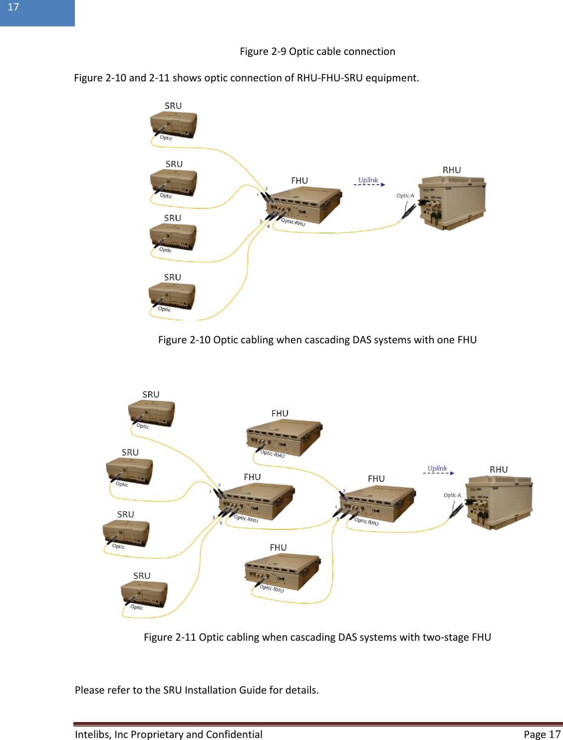
- 2. Installation Instruction
- 3. Product Manual / User Manual / RF Exposure Info
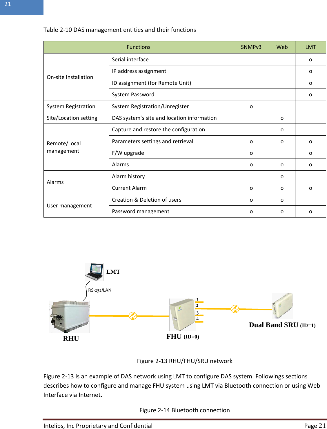
Product Manual / User Manual / RF Exposure Info
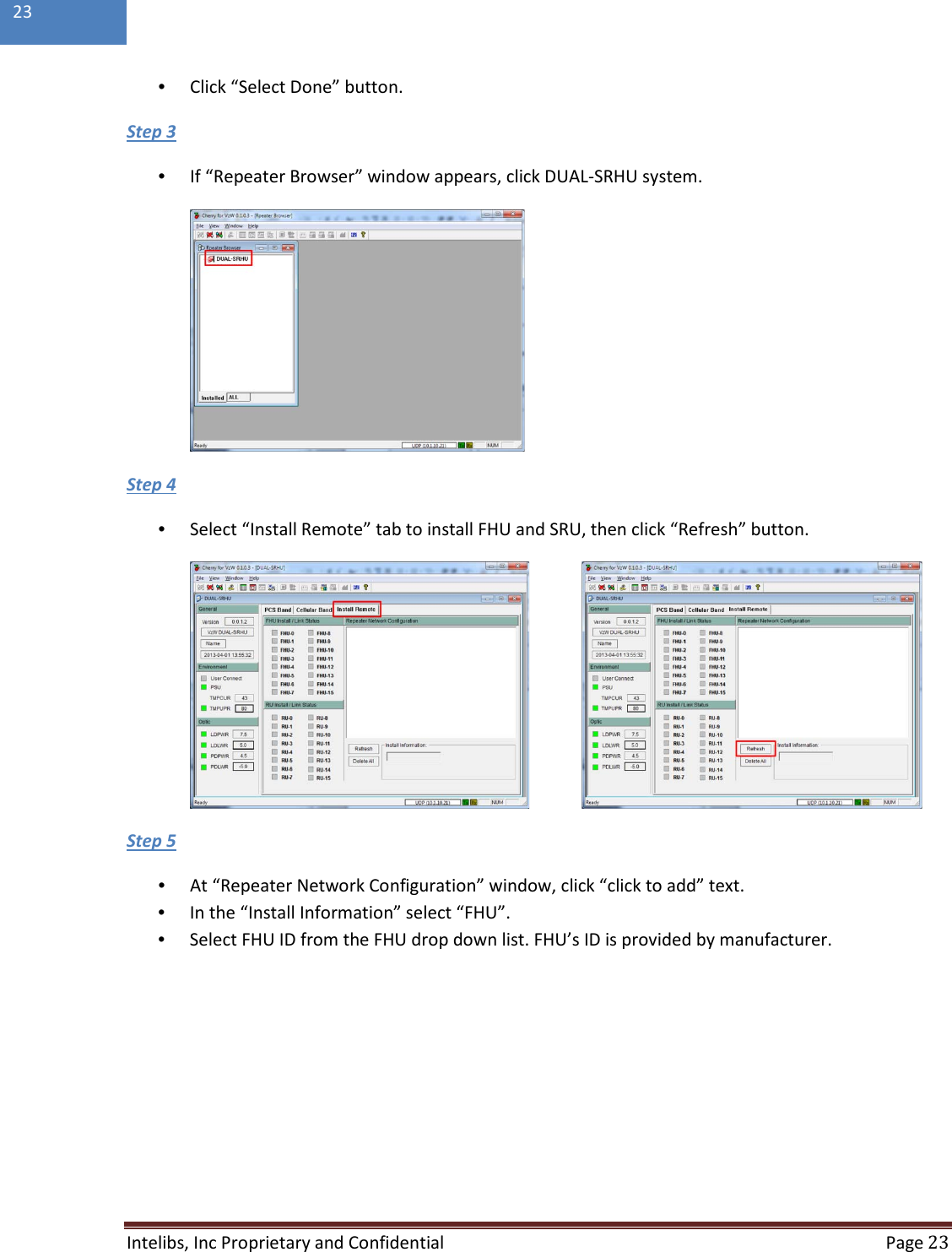
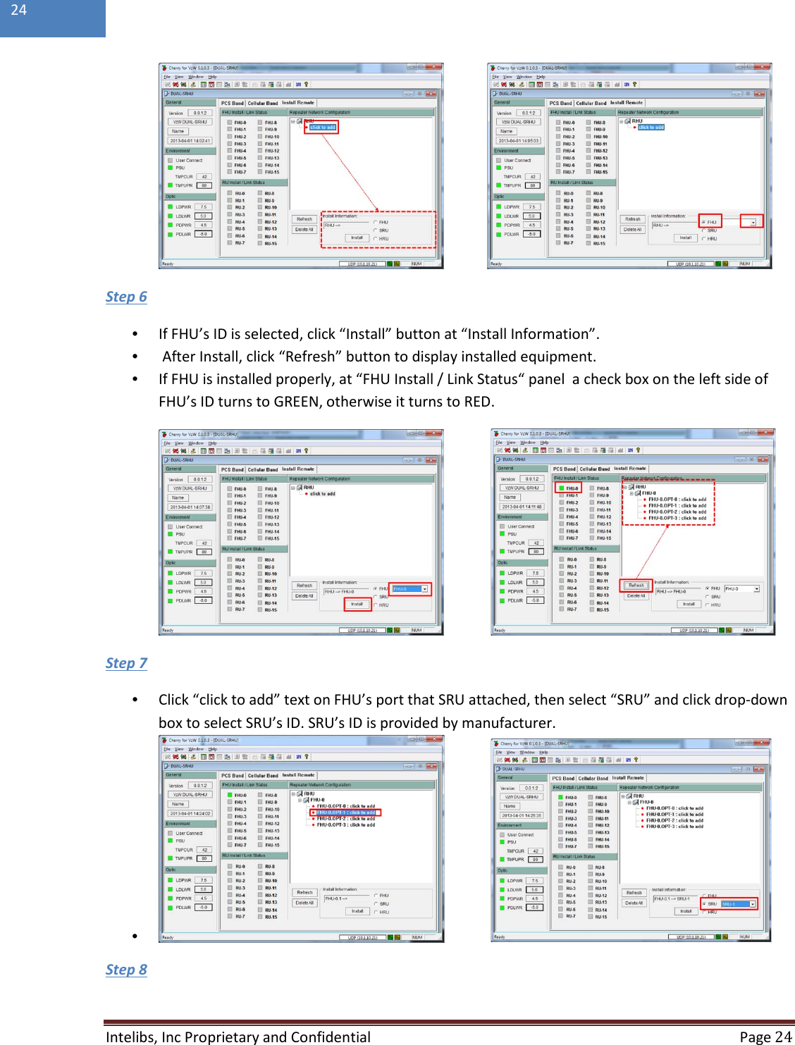
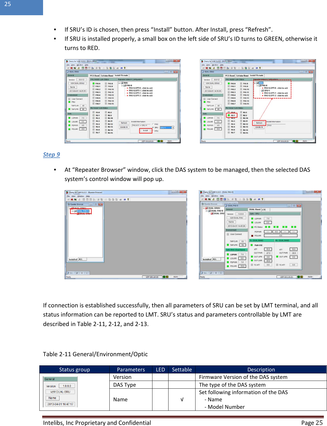
![Intelibs, Inc Proprietary and Confidential Page 22 22 2.7.1.1 Configuring FHU/SRU If one of Bluetooth or Ethernet connection has been established, LMT is ready to start. Launch the Local Management application by clicking the icon “Cherry” and follows the steps below. Step 1 • Launch the application “Cherry”. • Enter the password, click “Login”. • Click “Connect” icon on the left top corner of window. Step 2 • Select the connection parameters as follows: - Repeater Types: VzW Dual Band Small Power INB System - Connected Device: SRHU [Dual Band] - Connections o Serial Port: The port number established via Bluetooth or o UDP: IP address for the Ethernet interface](https://usermanual.wiki/Intelibs/D01T4JX2.Product-Manual-User-Manual-RF-Exposure-Info/User-Guide-2078308-Page-22.png)