User Manual

Intelibs, Inc.
RHU (Radio Hub Unit)
Product Manual
RHU Operational Manual for GPS-iDAS application
Version : 0.3
02-29-2016

Intelibs, Inc. Proprietary and Confidential Page 2
2
Contents
1 Introduction .......................................................................................................................................... 6
2 Product Description .............................................................................................................................. 8
2.1 Network configuration .................................................................................................................. 8
2.2 External interface ports ................................................................................................................ 9
2.3 Configuration of RHU inside........................................................................................................ 11
2.4 Mechanical Drawing ................................................................................................................... 13
2.5 RHU Block Diagram ..................................................................................................................... 14
2.6 RHU power and signal Distribution Diagram .............................................................................. 16
2.7 Technical Specifications .............................................................................................................. 17
2.7.1 General specifications ......................................................................................................... 17
2.7.2 Frequency allocation ........................................................................................................... 17
2.7.3 RHU RF specifications .......................................................................................................... 20
2.7.4 Power Specifications ........................................................................................................... 21
3 Installation .......................................................................................................................................... 22
3.1 Installation Requirements ........................................................................................................... 22
3.1.1 General Safety Precautions ................................................................................................. 22
3.2 Installation Tools ......................................................................................................................... 23
3.3 Item Check List ............................................................................................................................ 23
3.4 Mounting ..................................................................................................................................... 24
3.5 Link (Donor) Antenna .................................................................................................................. 25
3.6 Power cable ................................................................................................................................. 26
3.7 Optic cable .................................................................................................................................. 28
4 Configuration and Maintenance ......................................................................................................... 30
4.1 Configuring RHU using LMT ........................................................................................................ 32
4.1.1 LMT GUI (Graphic User Interface) Program ........................................................................ 32
4.1.2 System Requirement ........................................................................................................... 32
4.1.3 How to connect RHU using LMT GUI .................................................................................. 32
4.1.4 Main Window of LMT GUI ................................................................................................... 33
4.2 Detail description of Manu bar in GUI ........................................................................................ 35

Intelibs, Inc. Proprietary and Confidential Page 3
3
4.2.1 RHU window in GUI screen ................................................................................................. 35
4.2.2 Parameters details in RHU window .................................................................................... 35
4.2.3 SRU window in GUI screen .................................................................................................. 38
4.2.4 Parameters details in SRU window ..................................................................................... 38
4.3 Firmware download .................................................................................................................... 39
4.4 Additional function of RHU ......................................................................................................... 39
4.4.1 ASD (Auto Shutdown) Function .......................................................................................... 39
4.4.2 ALC (Auto Limit level Control) Function .............................................................................. 40
4.4.3 AGC (Auto Gain Control) Function ...................................................................................... 40
4.4.4 Sub-band selection Function ............................................................................................... 41
5 Appendix I. Ancillary Devices – Antenna, Cable and other Passive Device ........................................ 42
6 Human RF Exposure – Maximum Permissible Exposure Evaluation ................................................... 43

Intelibs, Inc. Proprietary and Confidential Page 4
4
FCC WARNING
This equipment generates or uses radio frequency energy. Changes or modifications to this equipment
may cause harmful interference unless the modifications are expressly approved in the instruction
manual. The user could lose the authority to operate this equipment if an unauthorized change or
modification is made.
This is NOT a CONSUMER device. It is designed for installation by FCC LICENSEES and QUALIFIED
INSTALLER. You MUST have an FCC LICENSE or express consent of an FCC Licensee to operate this device.
Unauthorized use may result in significant forfeiture penalties including penalties in excess of $100,000
for each continuing violation.
INFORMATION TO THE USER
This equipment has been tested and found to comply with the limits for a Class B digital device,
pursuant to Part 15 of the FCC Rules. These limits are designed to provide reasonable protection against
harmful interference in a residential installation.
This equipment generates, uses and can generate radio frequency energy and, if not installed and used
in accordance with the instructions, may cause harmful interference to radio communications. However,
there is no guarantee that the interference will not occur in a particular installation. If this equipment
does cause harmful interference to radio or television reception, which can be determined by turning the
equipment off and on, the user is encouraged to try to correct the interference by one or more of the
following measures:
· Reorient or relocate the receiving antenna.
· Increase the separation between the equipment and receiver.
· Connect the equipment to an outlet on a circuit different from that to which the receiver is connected.
· Consult the dealer for technical assistance.
Suitable for use in environmental air space in accordance with Section 300-22 (c) of the National
Electrical Code, and Sections 2-128, 12-010 (3), and 12-100 of the Canadian Electrical Code, Part 1,
C22.1.

Intelibs, Inc. Proprietary and Confidential Page 5
5
CAUTION Any changes or modifications not expressly approved by the manufacturer could void the
user's authority to operate the equipment. This equipment is intended for use only with Intelibs Hybrid
DAS systems.
Important health and safety precautions
When using this product, the safety precautions below must be taken to avoid possible legal liabilities
and damages. Retain and follow all product safety and operating instructions. Observe all warnings in
the operating instructions included with the device.
DANGER Only use antennas, transceivers and chargers approved by Intelibs. The use of any non-
approved antenna, transceiver and charger may be dangerous.
DANGER Allow only authorized personnel to service the DAS. Unauthorized service can invalidate the
warranty.
CAUTION Any modification of this product, including opening the unit, is prohibited and will void your
warranty. Any use of the product or its components for purposes not expressly authorized by this
document, including any use in an airplane or any other aviation application, is prohibited and will void
your warranty.
NOTE When using your device for prolonged periods of time, the device may become warm. In most
cases, this condition is normal and therefore should not be interpreted as a problem with the device.
Copyright information
© 2013 Intelibs, Inc. All rights reserved. The information contained herein is subject to change without
notice. Intelibs retains ownership of and all other rights to the material expressed in this document.
Any reproduction of the content of this document without prior written permission from Intelibs is
prohibited. Product names, logos, brands and other trademarks featured or referred to within this
document are the property of their respective owners.
The only warranties for Intelibs products and services are set forth in the express warranty statements
accompanying such products and services. Nothing herein should be construed as constituting an
additional warranty. Intelibs shall not be liable for technical or editorial errors or omissions contained
herein.

Intelibs, Inc. Proprietary and Confidential Page 6
6
1 Introduction
Radio Hub Unit (RHU) is a part of the Hybrid Distributed Antenna Systems (HDAS) to provide RF link
solution between RF Source and Remote Unit (RU). This RHU receives RF signal from antenna or wireline
and this unit filters, amplifies and converts RF signal into optic signal and transmits to RU through single
mode fiber. RHU is built on a small form factor with four antenna ports for 850MHz, 1900MHz and two
GPS antenna ports with the following features:
Support for a multi frequency band, multi-technology and multi-carrier
Wide band sub-channel selection by digital filter
Antenna isolation detection and oscillation protection function
Low Power consumption that can be operated by PoE or small AC/DC converter
20dBm Up Link composite power per band
SNMP based remote management support
Provide signal to remote unit (RU) site as far as 10Km distance via single mode fiber
Optic fiber sharing between different carriers
AGC (Auto Gain Control), ALC (Auto Level Limit Control) and ADS function
Compact and high capacity with scalable design
Ruggedized enclosure with more outdoor temperature compliance
GPS signal support and transmission with path redundancy function
Hybrid DAS RHU is comprised of the following subsystems:
FHU (Fiber Hub Unit): Interface unit between RHU and Remote Units, Convert O/E, compensate loss
and convert E/O. this unit has optic input port and optic output port.
SRU (Small power Remote Unit): Small power (23dBm per band) remote unit for indoor
HRU (High power Remote Unit): High power (30 ~ 43dBm per band) remote unit for outdoor
MU (Master Unit): Element management server
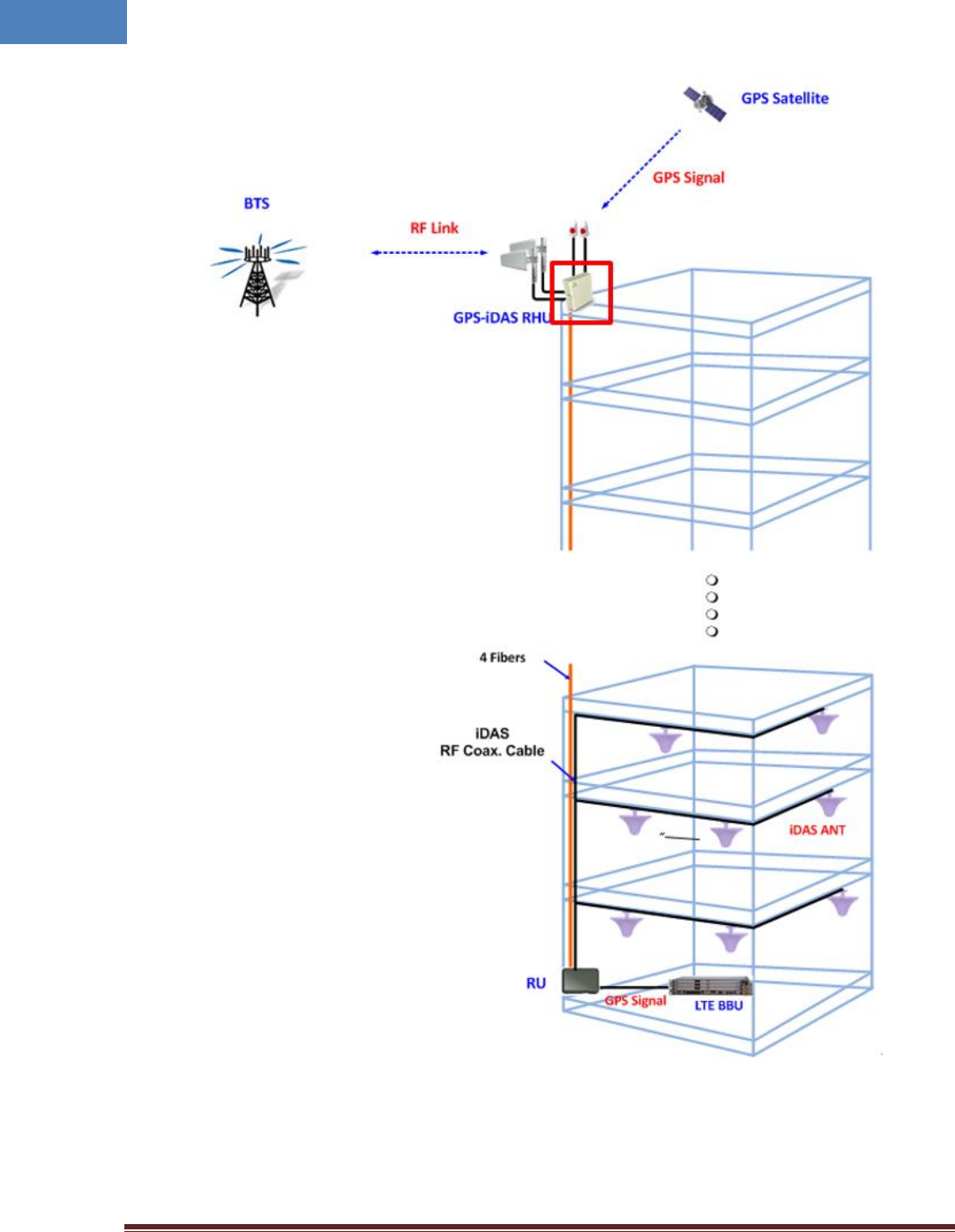
As illustrated in Figure 2-2, Hybrid DAS network is comprised of RHU, FHU and SRU/HRU. RHU provides
RUs can transmit signal to coverage area. An optic cable can be shared between different carriers and
different band.
Intelibs, Inc. Proprietary and Confidential Page 7
7
Figure 1-1 RHU-RU connection configuration
Intelibs, Inc. Proprietary and Confidential Page 8
8
2 Product Description
Radio Hub Unit (RHU) is a part of the Distributed Antenna System (DAS) to provide link between RF
Source and DAS RU, to fill coverage gaps and to enhance the quality of service of extending coverage of
mobile service.
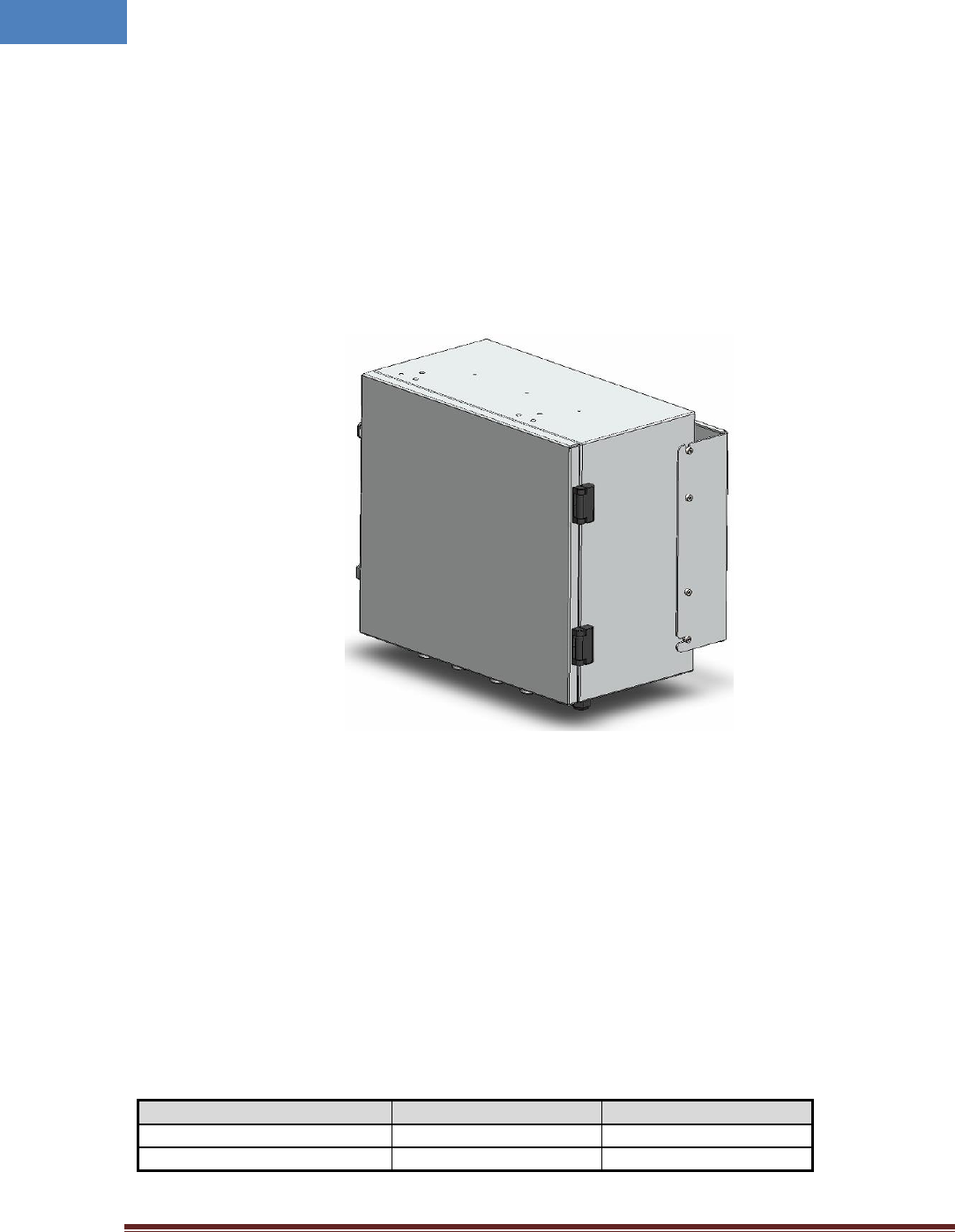
As shown in Figure 2-1, RHU is a compact platform with the natural heat convection. As unified form
factor, RHU services multiple technologies on a single platform with 850/1900MHz Dual-band and GPS
L1 band frequencies. It can be mounted on the wall or 19” rack. Variety of the donor antenna can be
used from Yagi directional antenna to high font-back-ratio directional antenna (or panel antenna).
Figure 2-1 RHU system
2.1 Network configuration
Three band RF signals such as 850/1900MHz and GPS L1 band from link and GPS antenna are fed to RHU
and RHU amplifies and converts into optical signal, and transmits this optical signals to remote RU
system. RHU can have up to 16 RUs and 5 FHU connections. RHU next release will support 700MHz,
2100MHz.
A fiber optic cable can be shared between different carriers or different band. Each frequency band
signals are combined to one wavelengths in a single fiber. Table 2-1 describes those wavelength
assignments. Maximum allowed optic loss between RHU and RU system is 10 dBo.
Table 2-1 Optic wavelength of each frequency band
Frequency band
Downlink Wavelength
Uplink Wavelength
850/1900MHz band
1,310 nm
1,550 nm
GPS L1 band
1,550 nm
1,310 nm
Intelibs, Inc. Proprietary and Confidential Page 9
9
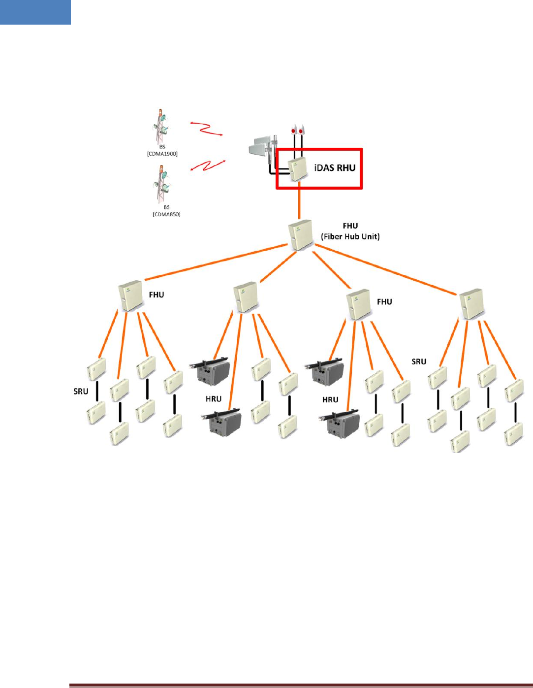
RHU systems with different operating frequency band can be interconnected via over-the-air. Typical
RHU-FHU-SRU/HRU network diagram is depicted in figure 2-2.
Figure 2-2 Typical iDAS RHU-FHU-RU network diagram
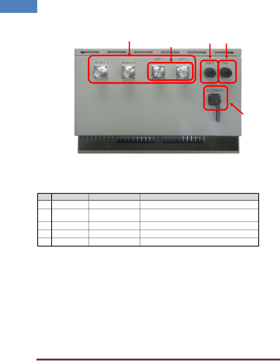
2.2 External interface ports
RHU has all interface connections at bottom side of an enclosure, which includes fiber, antennas and
power port. Figure 2-3 shows the bottom side of RHU system.
Intelibs, Inc. Proprietary and Confidential Page 10
10
Figure 2-3 Bottom view of RHU system
Table 2-2 Interface ports
No.
Port
Connector type
Description
1
MOBILE 1 ~ 4
DIN Female
Antenna RF cable connection port
2
GPS 1, 2
DIN Female
GPS Antenna cable connection port. These ports may
be used for Mobile or GPS antenna connection
3
FIBER
Cable gland
Fiber inlet port
4
PoE
Cable gland
Ethernet cable inlet port for PoE power supply
5
AC POWER
MS Female - 3PIN
110VAC Power cable connector
④
①
②
③
⑤
Intelibs, Inc. Proprietary and Confidential Page 11
11
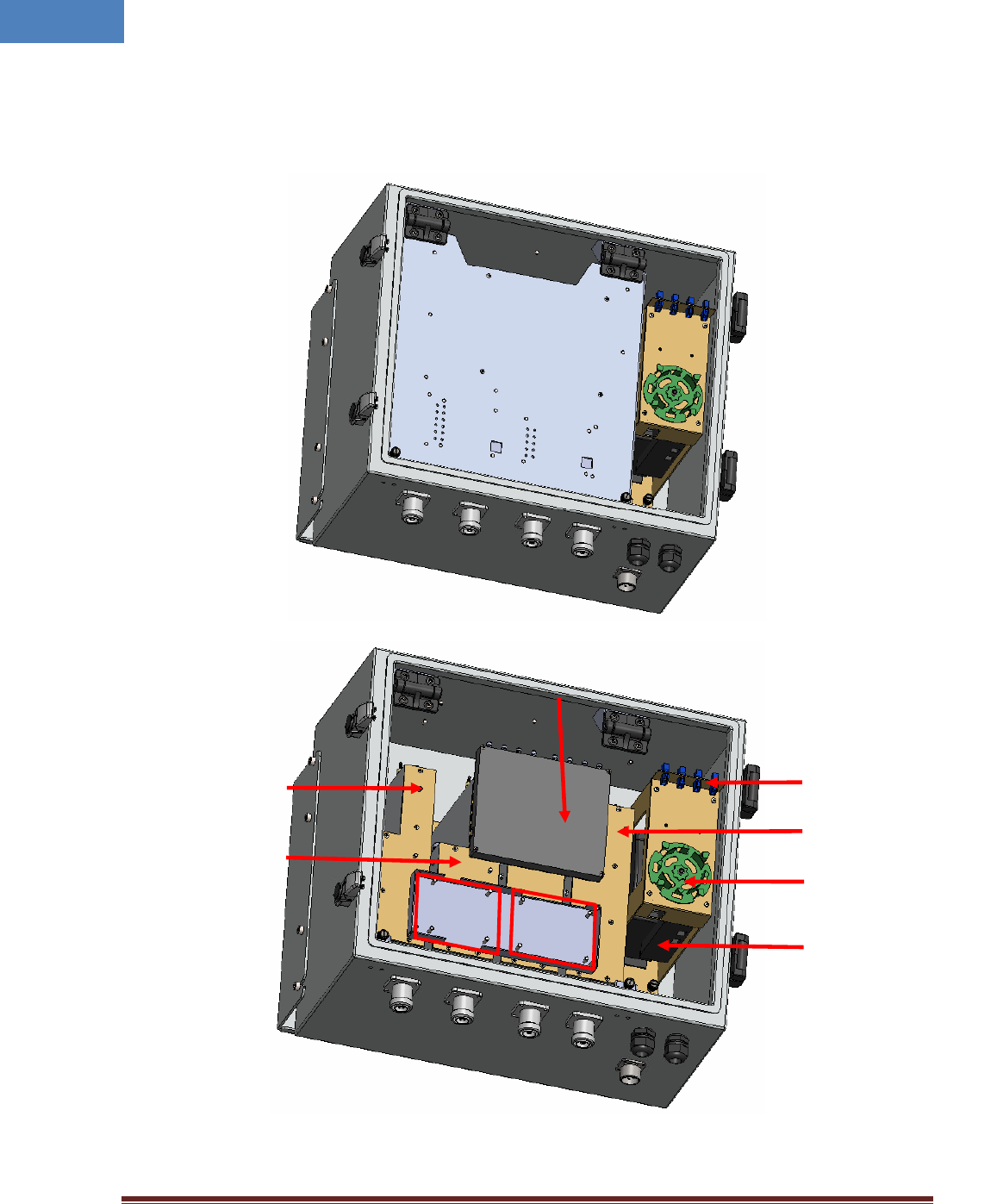
2.3 Configuration of RHU inside
RHU system is comprised of several internal modules such as RF band modules, GPS module, optic
module, and controller modules. Figure 2-4 shows inside of RHU system.
Figure 2-4 Module configuration of RHU inside
850RHM
1900RHM
RHOM
Optic Adapter
FEM
PoE Splitter or
ACDC converter
Optic tray
RFCU
GPSCU
Intelibs, Inc. Proprietary and Confidential Page 12
12
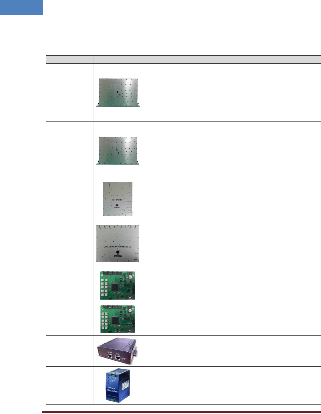
Table 2-3 RHU system’s modules
Module
Picture
Description
850 RHM
[Down Link]
This module filters 850 DL RF signal from link antenna, amplifies with
low noise, selects sub-channel by digital band pass filters and transmits
the selected 850 DL RF signal to optical module.
[Up Link]
This module filters 850 UL RF signal from optical module, selects sub-
channel by digital band pass filters, amplifies to get high power and
transmits 850 UL RF signal to antenna.
1900 RHM
[Down Link]
This module filters 1900 DL RF signal from link antenna, amplifies with
low noise, selects sub-channel by digital band pass filters and transmits
the selected 1900 DL RF signal to optical module.
[Up Link]
This module filters 1900 UL RF signal from optical module, selects sub-
channel by digital band pass filters, amplifies to get high power and
transmits 1900 UL RF signal to antenna.
FEM
This unit filters GPS L1 band signal, amplifies by low noise, converts
GPS signal into optical signal and transmits this optic signal to RU site
via fiber. This unit has two GPS ports to support path redundancy
function. If one GPS fails, second GPS port switch over automatically.
RHOM
[Down Link]
This module converts RF signal from 850/1900 RHM into optical signal
and transmits to RU site via fiber.
[Up Link]
This module converts optical signal coming from fiber into RF UL signals
and amplifies UL signals to compensate fiber loss and transmits to
850/1900 RHM.
RF Controller
(RFCU)
This module controls and monitors all parameters of 850RHM,
1900RHM and RHOM which related to 850/1900 DL/UL RF circuits.
GPS Controller
(GPSCU)
This module manages all parameters of RF circuits of two GPS path.
PoE Splitter
This module receives DC voltage through the Ethernet cable and
supplies DC voltage to each module. RHU uses one of PoE Splitter and
ACDC converter according to installation environment.
ACDC Converter
This module converts AC110V voltage to DC 24V and supply this DC
voltage to each active module. RHU uses one of PoE Splitter and ACDC
converter according to installation environment.
Intelibs, Inc. Proprietary and Confidential Page 13
13
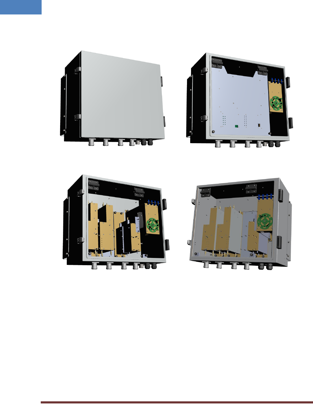
2.4 Mechanical Drawing
Figure 2-5 RHU Outside drawing
Figure 2-6 RHU Inside drawing
Intelibs, Inc. Proprietary and Confidential Page 14
14
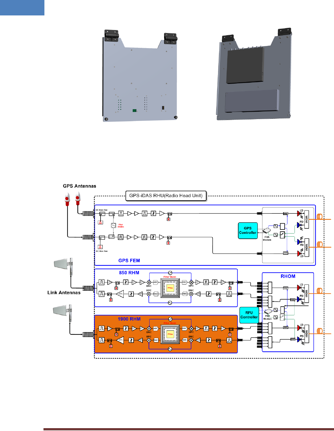
Figure 2-7 RHU Inner door drawing
2.5 RHU Block Diagram
Figure 2-8 RHU system RF Block Diagram
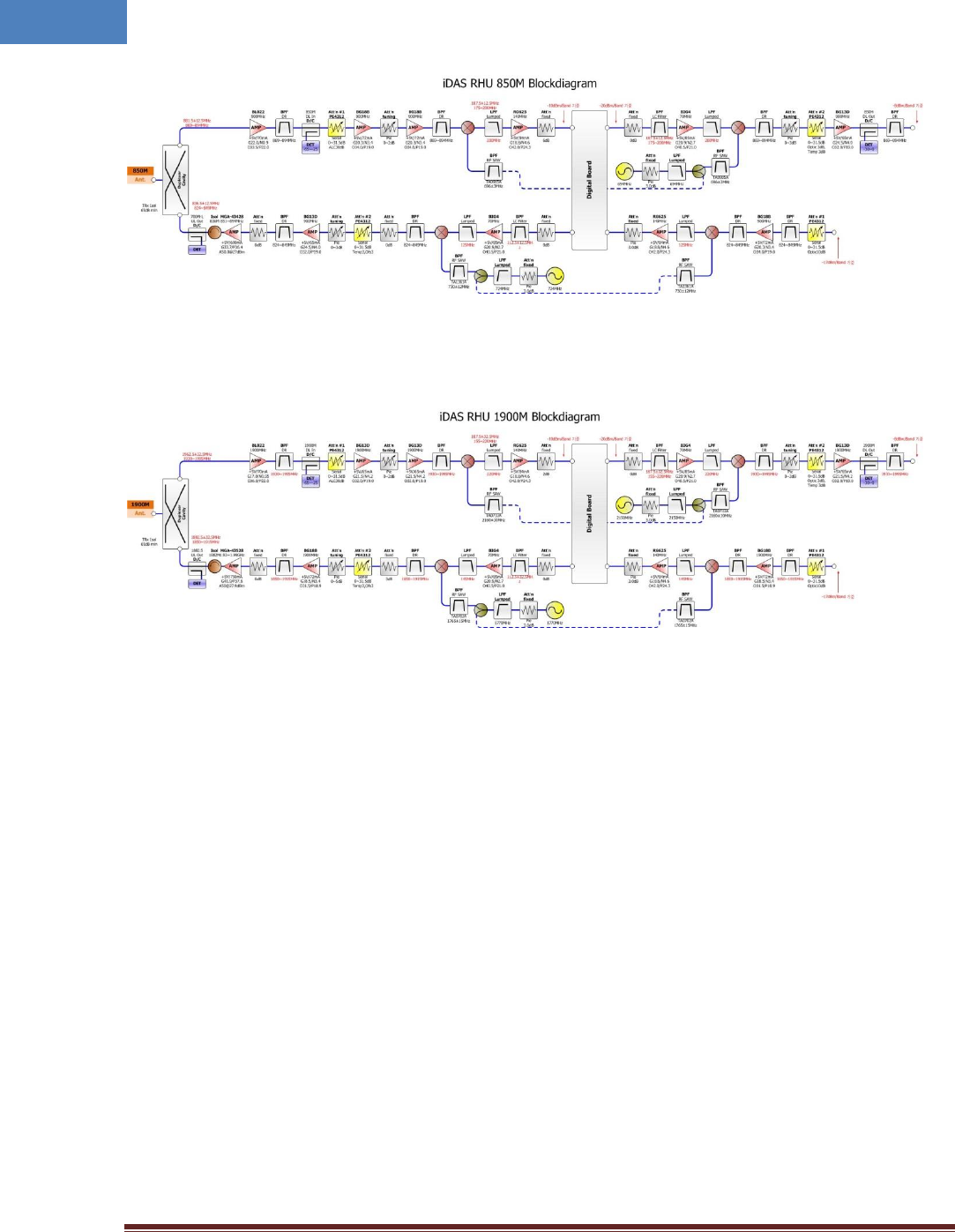
Intelibs, Inc. Proprietary and Confidential Page 15
15
Figure 2-9 850MHz RHU RF Block Diagram
Figure 2-10 1900MHz RHU RF Block Diagram
Intelibs, Inc. Proprietary and Confidential Page 16
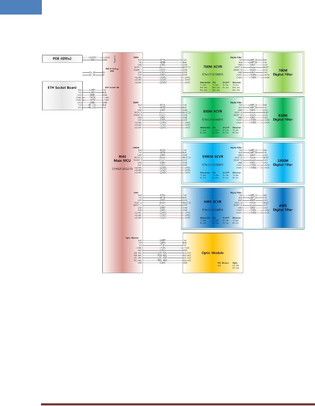
16
2.6 RHU power and signal Distribution Diagram
Intelibs, Inc. Proprietary and Confidential Page 17
17
2.7 Technical Specifications
2.7.1 General specifications
Table 2-4 General Specifications
Specification
Values
Enclosure Type
Cabinet
Dimension (mm)
17.5 (H) X 19.5 (W) X 11 (D) inch
Weight (Kg)
57lb (26 Kg)
Power Supply
110-120Vac (Tolerance ±10%), 60Hz
PoE Input (IEEE 802.3at)
Power Connector
MS Connecter
RF In/Out Port
DIN Type Female, bottom part
Optic Connector Type
LC/UPC inside
Optic Wavelength
DL: 1310nm / UL: 1550nm for 850/1900/GPS
DL: 1550nm / UL: 1550nm for GPS only
Operating Temperature
-30℃ ~ 55℃
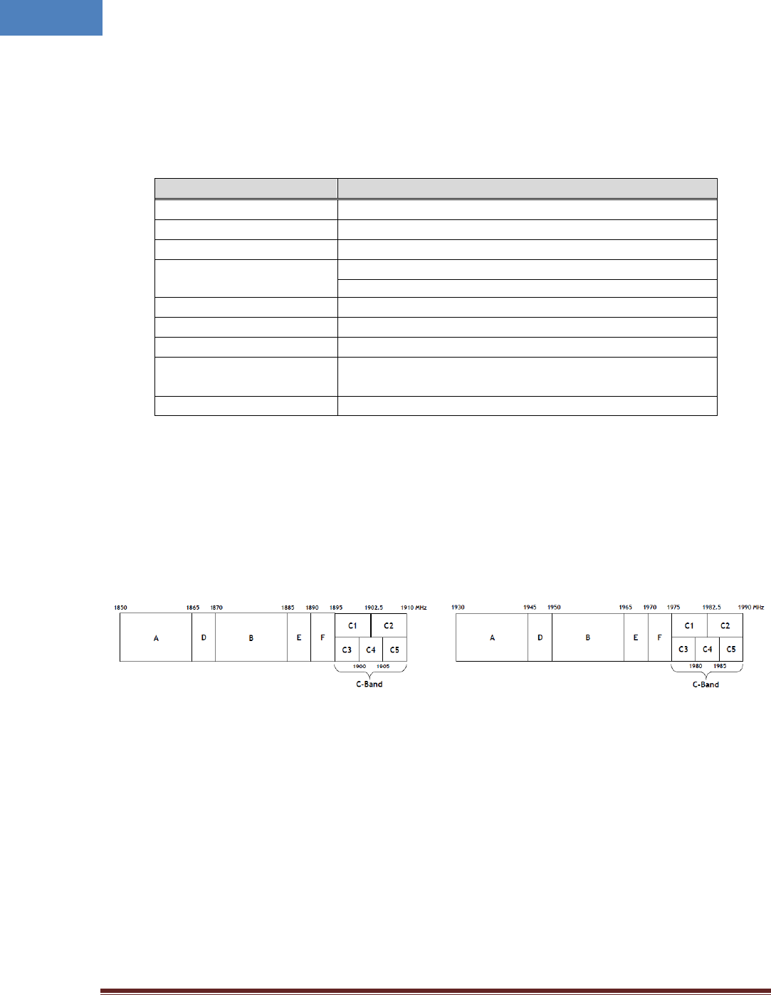
2.7.2 Frequency allocation
2.7.2.1 1900 MHz band
Figure 2-8 Frequency allocation of 1900 MHz band
Uplink Downlink

Intelibs, Inc. Proprietary and Confidential Page 18
18
Table 2-5 1900 MHz Frequency map
Sub-Band
Channel #
DL (MHz)
UL (MHz)
Remarks
A
25
1931.25
1851.25
DL : 1930.625~1944.375MHz
UL : 1850.625~1864.375MHz
75
1933.75
1853.75
100
1935.00
1855.00
125
1936.25
1856.25
150
1937.50
1857.50
175
1938.75
1858.75
200
1940.00
1860.00
225
1941.25
1861.25
250
1942.50
1862.50
275
1943.75
1863.75
D
325
1946.25
1866.25
DL : 1945.625~1949.375MHz
UL : 1865.625~1869.375MHz
350
1947.50
1867.50
375
1948.75
1868.75
B
425
1951.25
1871.25
DL : 1950.625~1964.375MHz
UL : 1870.625~1884.375MHz
450
1952.50
1872.50
475
1953.75
1873.75
500
1955.00
1875.00
525
1956.25
1876.25
550
1957.50
1877.50
575
1958.75
1878.75
600
1960.00
1880.00
625
1961.25
1881.25
650
1962.50
1882.50
675
1963.75
1883.75
E
725
1966.25
1886.25
DL : 1965.625~1969.375MHz
UL : 1885.625~1889.375MHz
750
1967.50
1887.50
775
1968.75
1888.75
F
825
1971.25
1891.25
DL : 1970.625~1974.375MHz
UL : 1890.625~1894.375MHz
850
1972.50
1892.50
875
1973.75
1893.75
C1
925
1976.25
1896.25
C3 Band
950
1977.50
1897.50
975
1978.75
1898.75
1000
1980.00
1900.00
1025
1981.25
1901.25
C4 Band
1050
1982.50
1902.50
C2
1075
1983.75
1903.75
1100
1985.00
1905.00
1125
1986.25
1906.25
C5 Band
1150
1987.50
1907.50
1175
1988.75
1908.75
Intelibs, Inc. Proprietary and Confidential Page 19
19
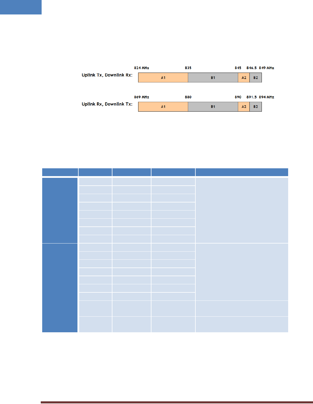
2.7.2.2 850 MHz band
Figure 2-9 Frequency allocation of 850 MHz band
Table 2-6 850 MHz Frequency map
Sub-Band
Channel #
DL (MHz)
UL (MHz)
Remarks
A1
1019
869.88
824.88
DL : 869.265~879.105MHz
UL : 824.265~834.105MHz
37
871.11
826.11
78
872.34
827.34
119
873.57
828.57
160
874.8
829.8
201
876.03
831.03
242
877.26
832.26
283
878.49
833.49
B1
384
881.52
836.52
DL : 880.905~889.515MHz
UL : 835.905~844.515MHz
425
882.75
837.75
466
883.98
838.98
507
885.21
840.21
548
886.44
841.44
589
887.67
842.67
630
888.9
843.9
A2
691
890.73
845.73
DL : 890.115~891.345MHz
UL : 845.115~846.345MHz
B2
777
893.31
848.31
DL : 892.695~893.925MHz
UL : 847.695~848.925MHz
2.7.2.3 GPS L1 Band
- 1575.42 +/- 10MHz band

Intelibs, Inc. Proprietary and Confidential Page 20
20
2.7.3 RHU RF specifications
Table 2-7 RF specifications
Item
Specification
Remarks
DL Frequency
Range
850MHz
Sub-band selection in 869 ~ 894MHz
1900MHz
Sub-band selection in 1930 ~ 1995MHz
700 LTE*
A/B/Upper C band selection in 728 ~ 757MHz
2100 AWS*
Sub-band selection in 2110 ~ 2155MHz
UL Frequency
Range
850MHz
Sub-band selection in 824 ~ 849MHz
1900MHz
Sub-band selection in 1850 ~ 1915MHz
700 LTE*
A/B/Upper C band selection in 698 ~ 787MHz
2100 AWS*
Sub-band selection in 1710 ~ 1755MHz
DL Input Power
-60 ~ -30dBm/total, the recommended input power is more than
-50dBm/total from donor antenna.
UL Output Power
850MHz
+20dBm /total for 850MHz RHU ANT Port
1900MHz
+20dBm/total for 1900MHz RHU ANT Port
700 LTE*
+20dBm/total for 700MHz RHU ANT Port
2100 AWS*
+20dBm/total for 1700MHz RHU ANT Port
RHU Gain
DL: 10dB ~ 40dB
UL:10dB ~ 40dB
FWD Spurious
Comply to 3GPP, 3GPP2 and FCC regulation
Gain Control
Range
FWD: 30dB by 1dB Step
RVS: 30dB by 1dB Step
RU OLC Gain
EVM degradation
Less than 2% compare with RF Source @ max. output power
Frequency Stability
0.02ppm max.
Pass-Band Ripple
850MHz
3dB max. in any sub-band BW
1900MHz
3dB max. in any sub-band BW
700 LTE*
2dB max. in Any A/B/C or upper C band
2100 AWS*
2dB max. Any sub-band
System Delay
Tx: 2us. Max
Rx: 2us. Max
Tx-Rx Isolation
100dB min. @Between RU Tx Output and RHU Rx Output
Impedance
50 Ohm
VSWR
1.5 : 1 max. @ All input/output ports
Optical
Wavelength
Mobile
DL: 1310nm
UL: 1550nm
GPS
DL: 1550nm
UL: 1310nm
RF Connector
DIN Female
*) 700 MHz and 2100 MHz support available in next release

Intelibs, Inc. Proprietary and Confidential Page 21
21
2.7.4 Power Specifications
Table 2-8 Power specifications
Item
Specification
Rated Input Voltage
1. PoE Input (IEEE 802.3at compatible) or 110-120V AC, 60 Hz Input
Permissible range
2. Tolerance ±10%
Power consumption
80W, maximum
70 W, typical
Power Connector
Gland type for PoE, MS Male type for AC

Intelibs, Inc. Proprietary and Confidential Page 22
22
3 Installation
3.1 Installation Requirements
Before and during installation, the following should be carefully verified in order to avoid any
problem:
Faulty Cabling/Connectors: Fiber cable and connectors must be verified prior to plugging
into the RHU
Dirty Connectors and ports
Faulty Radio Hub Unit (RHU) components
RF source equipment issue
External RF Interface problem such as antenna port
The following guidelines are required when the RHU is installed on the 19” rack of Headend room:
Locate the equipment with the space for the sufficient airflow to prevent build-up from
the overheating. Do not compromise the amount of airflow required for safe operation of
the equipment.
Verify the power connection and Fiber cables prior to turning on the systems.
WARNING: Equipment loading must be verified prior to mounting the equipment on the wall or 19”
rack.
3.1.1 General Safety Precautions
The following precautions apply to the RHU:
The units have no user-serviceable parts. Faulty or failed units are fully replaceable through
Intelibs.
When the Fiber cable is connected to the equipment, the connectors must be free from the dust
and connected according to the cable manufacturer’s instructions. (WARNING: For the safety,
DO NOT conduct eye-contact at the connector ends of the fibers or the port of the RHU and SRU
unless equipped with protection goggle. Invisible infrared radiation may be present at the front
panel of the RHU and SRU. Do not remove the fiber port dust caps unless the port is going to be
used. Do not stare directly into a fiber port.)
Intelibs, Inc. Proprietary and Confidential Page 23
23
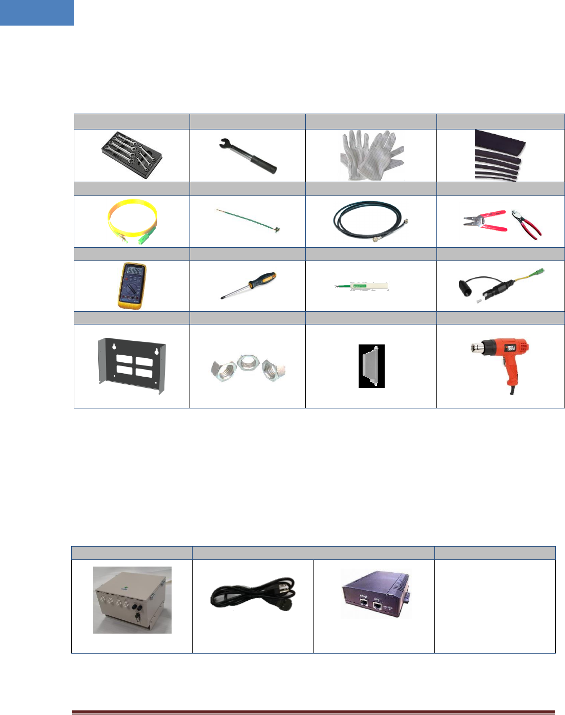
3.2 Installation Tools
Table 3-1 Installation tools
Torque Wrench
Torque Wrench
ESD Gloves
Shrink Tubes
LC/UPC Optic Fiber, 10m
Ground wire line
2ea of ANT RF Cable
Wire Stripper & Cutter
Digital Multi-meter
Screw Driver
Optic connector cleaner
Optic cable, 3m SC/APC
Mounting bracket
Fixing bolts and nuts
2 Wideband Link Antennas
Heat Gun
3.3 Item Check List
Check that all the following items have been included with the box delivered. If anything is missing,
please contact Intelibs.
Table 3-2 Item check list
RHU
AC power cable or PoE Injector
RHU 1set
AC power cable:
1.5m, 1 ea
PoE Injector 1 ea
Intelibs, Inc. Proprietary and Confidential Page 24
24
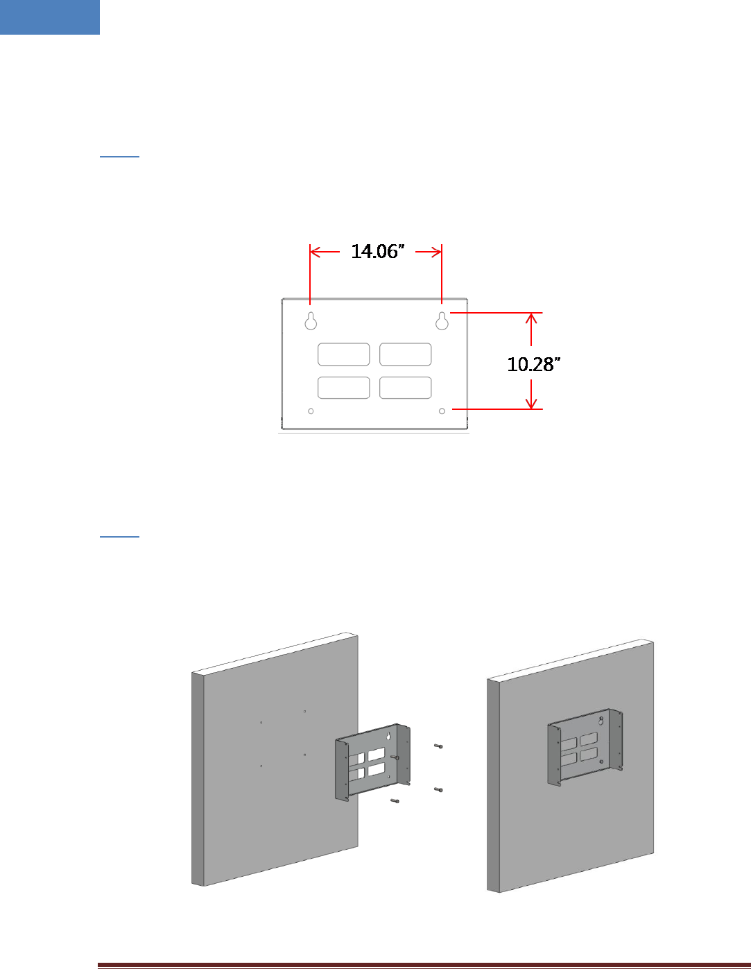
3.4 Mounting
RHU supports wall mount. The following diagrams illustrate the methods for mounting RHU on a typical
wall.
Step 1
• Mark the upper position by using the wall mount bracket drawing paper.
• Mark the lower position by using the wall mount bracket drawing paper.
Figure 3-1 Mark the installation position
Step 2
• Install wall mount bracket to the wall using 4 anchor bolts.
Figure 3-2 Install the wall mount bracket
Intelibs, Inc. Proprietary and Confidential Page 25
25
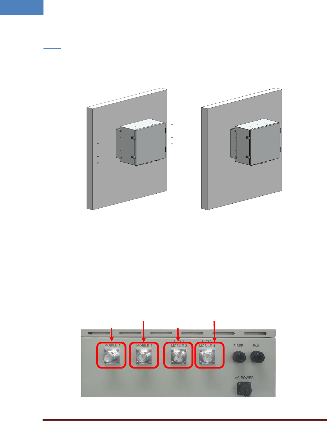
Step 3
• Install the RHU system as figure below.
Figure 3-3 Install the RHU to the installed wall mount bracket
3.5 Link (Donor) Antenna
RHU has four antenna ports. Two are the ports for 850MHz/1900MHz antennas and another two are the
ports for two GPS antennas. Connect each DIN-type male antenna cable to the desired antenna port, as
Figure below.
Figure 3-4 Link/GPS Antenna port
850MHz
1900MHz
GPS2
GPS1
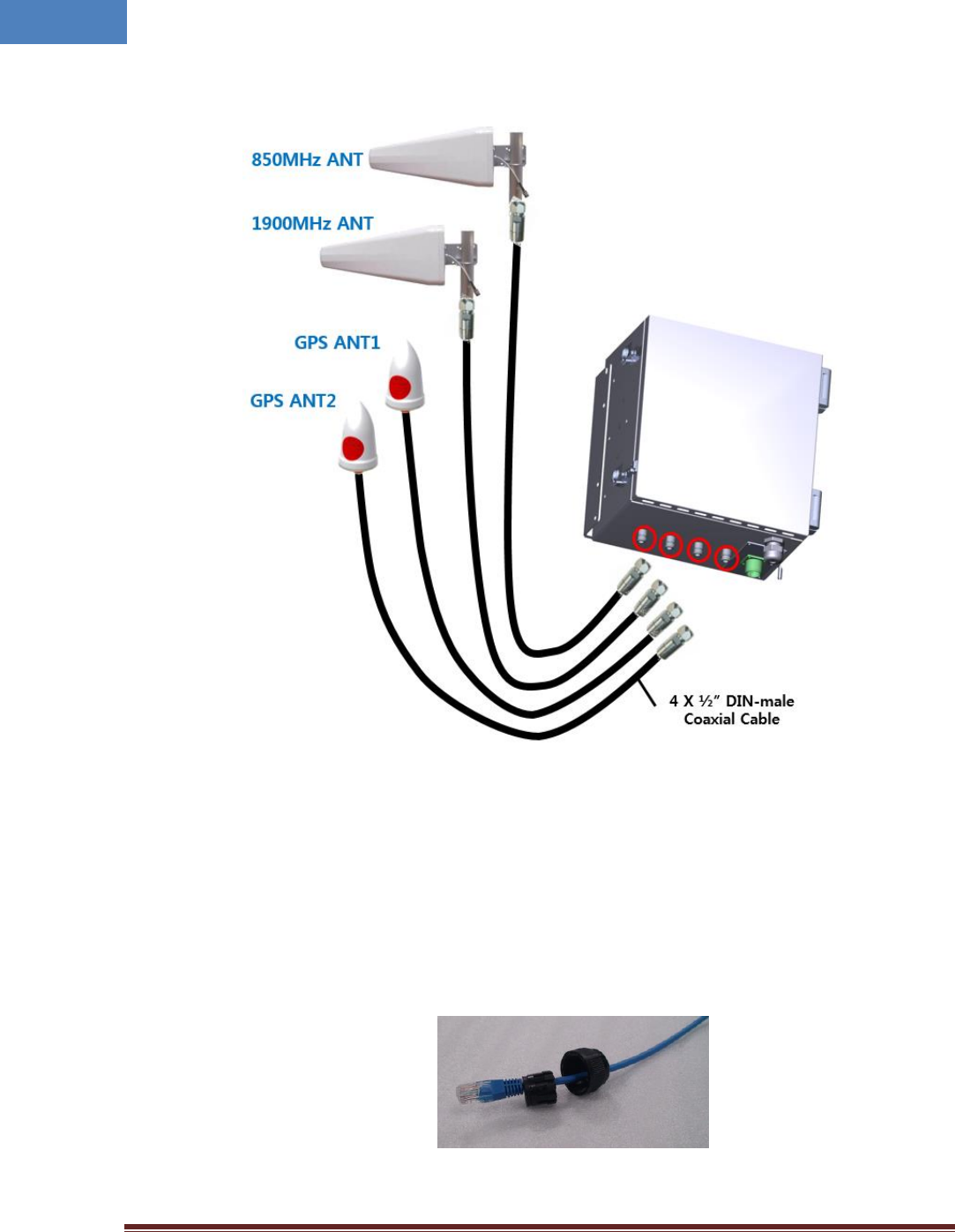
Intelibs, Inc. Proprietary and Confidential Page 26
26
Figure 3-5 Link/GPS Antenna connection diagram
3.6 Power cable
1. In case of PoE Input
1) Please release gland cap and put Ethernet cable into cap and water protection rubber ring
as following picture.
2) Reassemble cable gland to insert Ethernet cable into RHU enclosure as follows.
Intelibs, Inc. Proprietary and Confidential Page 27
27
3) Please connect Ethernet cable to RJ-45 connector of RHU inside as following picture. And
you can find LEDs are turned on if Ethernet cable has DC power.
Figure 3-6 Power cable connection (PoE type)
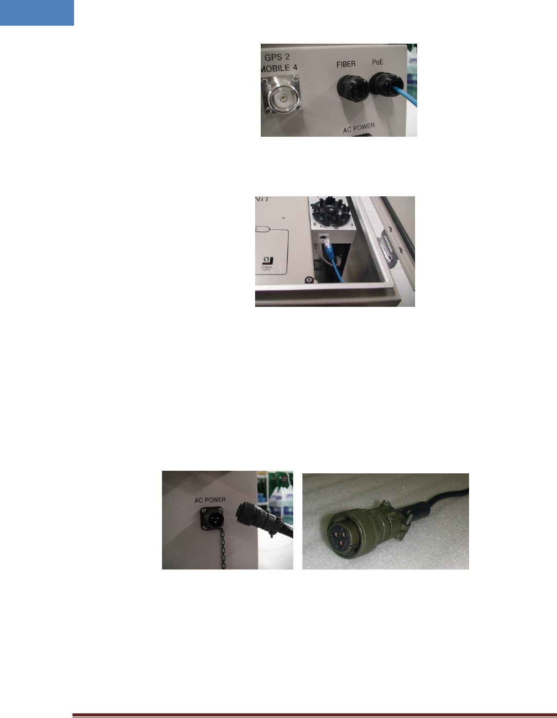
2. The case of AC Input
Connect MS connector-type power cable which is supplied with RHU to the “AC POWER” port.
When connecting the end terminal, align connector at latch and hole position as figure below.
Figure 3-7 Power cable connection (AC type)
Intelibs, Inc. Proprietary and Confidential Page 28
28
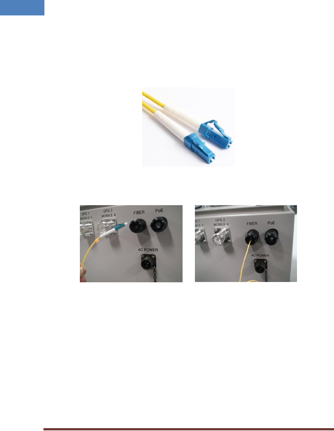
3.7 Optic cable
RHU provides four optic ports. Fiber_1 and Fiber_2 are the ports to connect with SRU, and Fiber_3 and
Fiber_4 are the ports to connect with GPS BEU. The type of fiber connector is all LC/UPC type connector
as figure below.
[LC/UPC type fiber connector]
Figure 3-8 LC/UPC fiber connector connection
Connect the fiber connector to the desired optic port in RHU. When connecting the optic connector,
align the connector at latch and hole position, then plug in deeply to get the right connection.
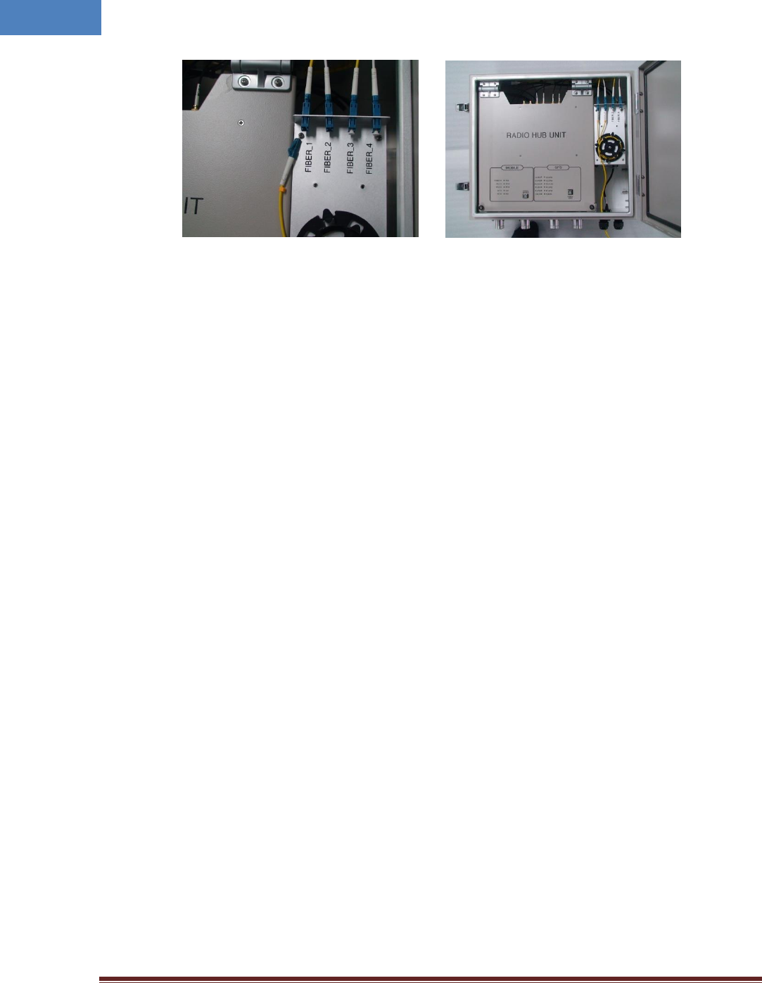
Intelibs, Inc. Proprietary and Confidential Page 29
29
Figure 3-9 Fiber cable connection on RHU
Intelibs, Inc. Proprietary and Confidential Page 30
30
4 Configuration and Maintenance
RHU can be configured in three ways via remote internet connection or local serial port connection.
SNMPv3 interface through the internet
Web interface through the internet
Local management interface through the internet and serial connection.
Master Unit is a remote management system that provides SNMP v3 and Web interface, and maintains
all functions of iDAS system including configurations, monitoring, and real time alarm reporting.
LMT (Local Management Terminal) is local management interface through serial interface.
The configuration and maintenance for RHU is performed by accessing RHU through any interfaces.
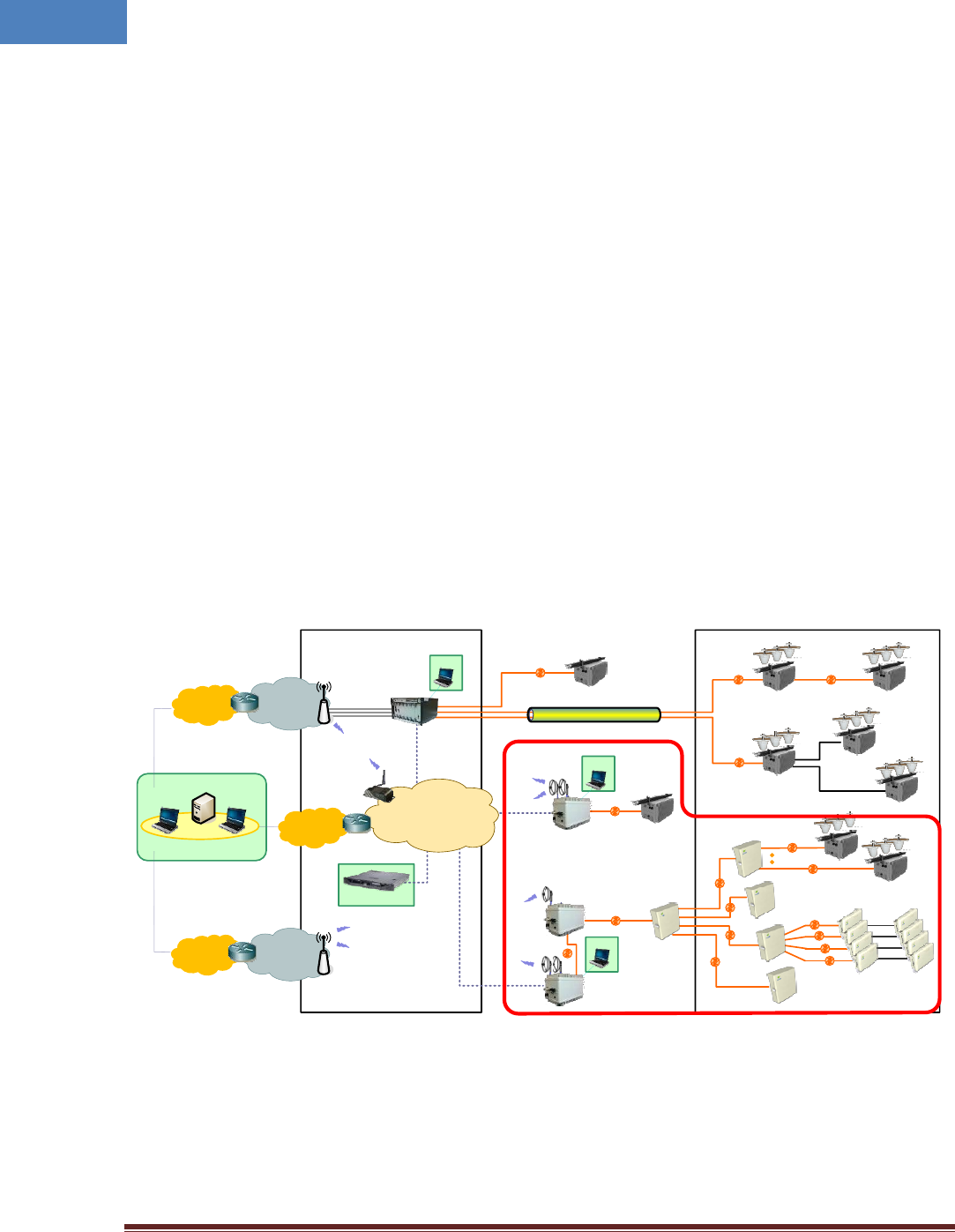
Figure below describes a typical iDAS management system network and the entities and management
system network of RHU-iDAS is a part of total DAS management. Red marked part is the management
network of RHU iDAS system.
In-Building
Wireless
network
RU-LTE
RF
BTS
RU-DUAL
RU-AWS
RU-DUAL
MHU
RHU-LTE
Wireless
network
BTS
FHU
SRU-DUAL SRU-LTE
RU-DUAL
Head end
Master Unit
IP Network
Ethernet
Ethernet
Modem
Internet
Internet
Internet
WEB
SNMP
LMT
OAM Plane
FHU
LMT
Ethernet
RHU-DUAL
Router
RF
RU-DUAL
Outdoor/In-Building
Optic
RHU-DUAL RU-DUAL
Ethernet
RF
RF
LMT
RF
LMT
RU-LTE
RF
Figure 4-1 DAS management network and entities
Intelibs, Inc. Proprietary and Confidential Page 31
31
Table 4-1 DAS management entities and their functions
Functions
SNMPv3
Web
LMT
On-site Installation
Serial interface
o
IP address assignment
o
ID assignment (for Remote Unit)
o
System Password
o
System Registration
System Registration/Unregister
o
Site/Location setting
DAS system’s site and location information
o
Remote/Local
management
Capture and restore the configuration
o
Parameters settings and retrieval
o
o
o
F/W upgrade
o
o
Alarms
o
o
o
Alarms
Alarm history
o
Current Alarm
o
o
o
User management
Creation & Deletion of users
o
o
Password management
o
o
o
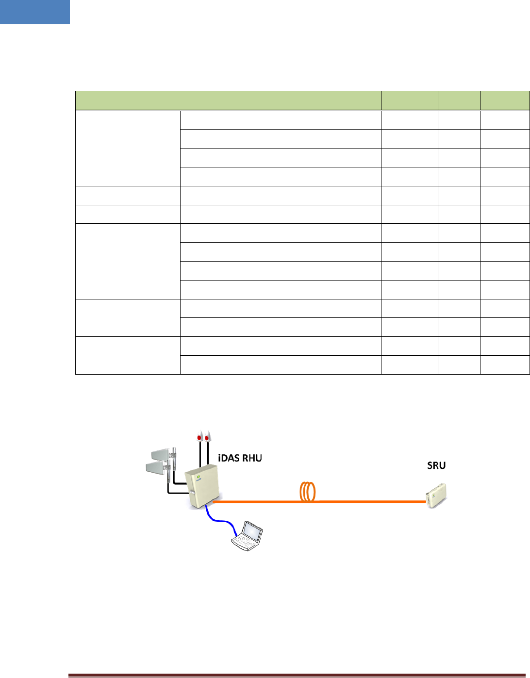
Figure 4-2 RHU-SRU network
Figure 4-2 is an example of DAS network using LMT to configure DAS system. Following sections
describes how to configure and manage RHU system using LMT via serial/LAN connection or using Web
Interface via Internet.
Intelibs, Inc. Proprietary and Confidential Page 32
32
4.1 Configuring RHU using LMT
If one of serial connection has been established, LMT is ready to start. Launch the Local Management
application by clicking the icon “iDAS” and refer to following information.
4.1.1 LMT GUI (Graphic User Interface) Program
This program is a iDAS management program and provides status of all DAS parameter and can
control each parameter you want to control.
4.1.2 System Requirement
System: Desktop or laptop PC
OS: Windows XP or later version. GUI developed under Windows 7.
Resolution: 1024 768 or more
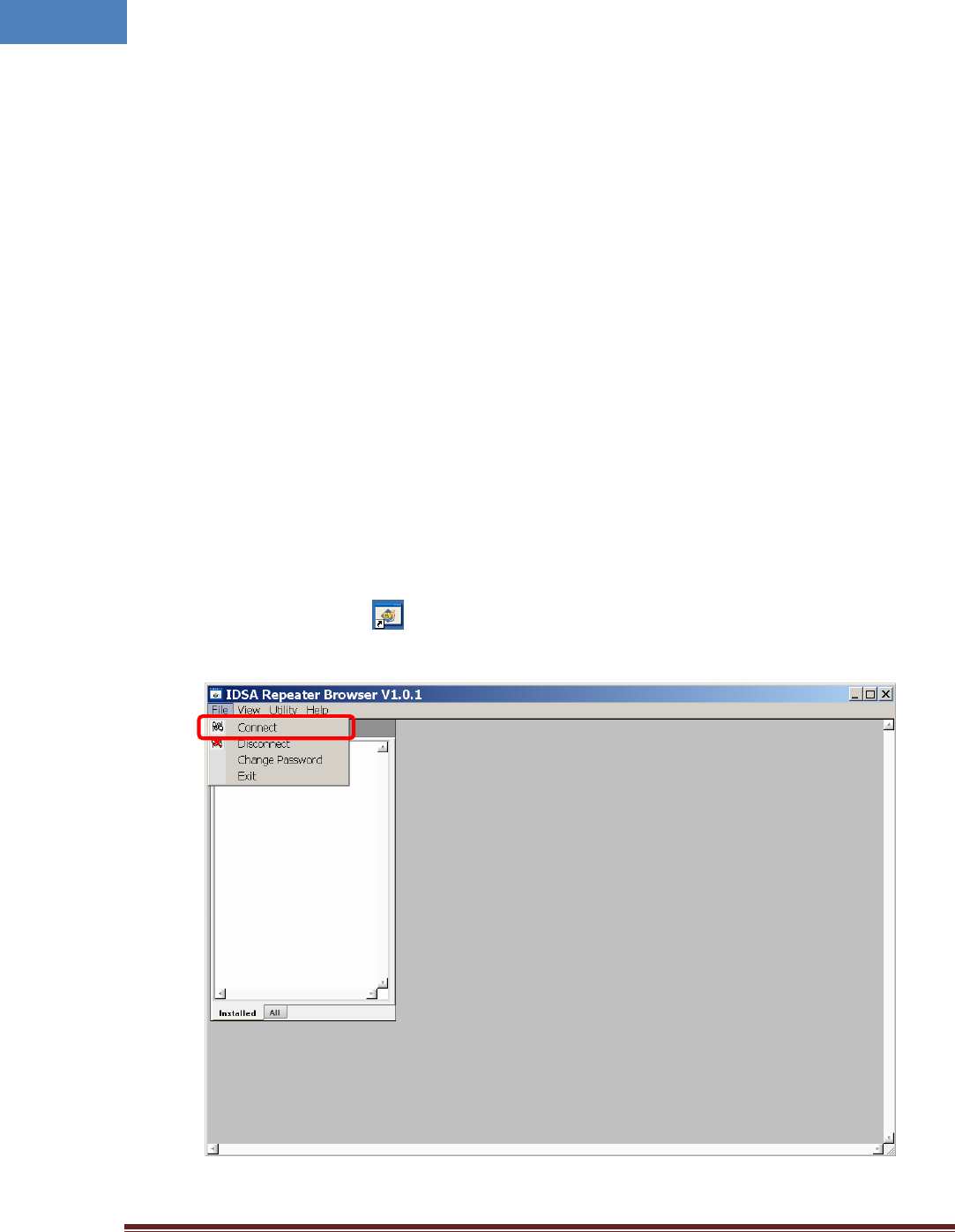
4.1.3 How to connect RHU using LMT GUI
1. Double click iDAS.exe ( ) icon to open LMT GUI of RHU. Then you can see following screen.
Press “Connect” button in drop down menu of File.
Intelibs, Inc. Proprietary and Confidential Page 33
33
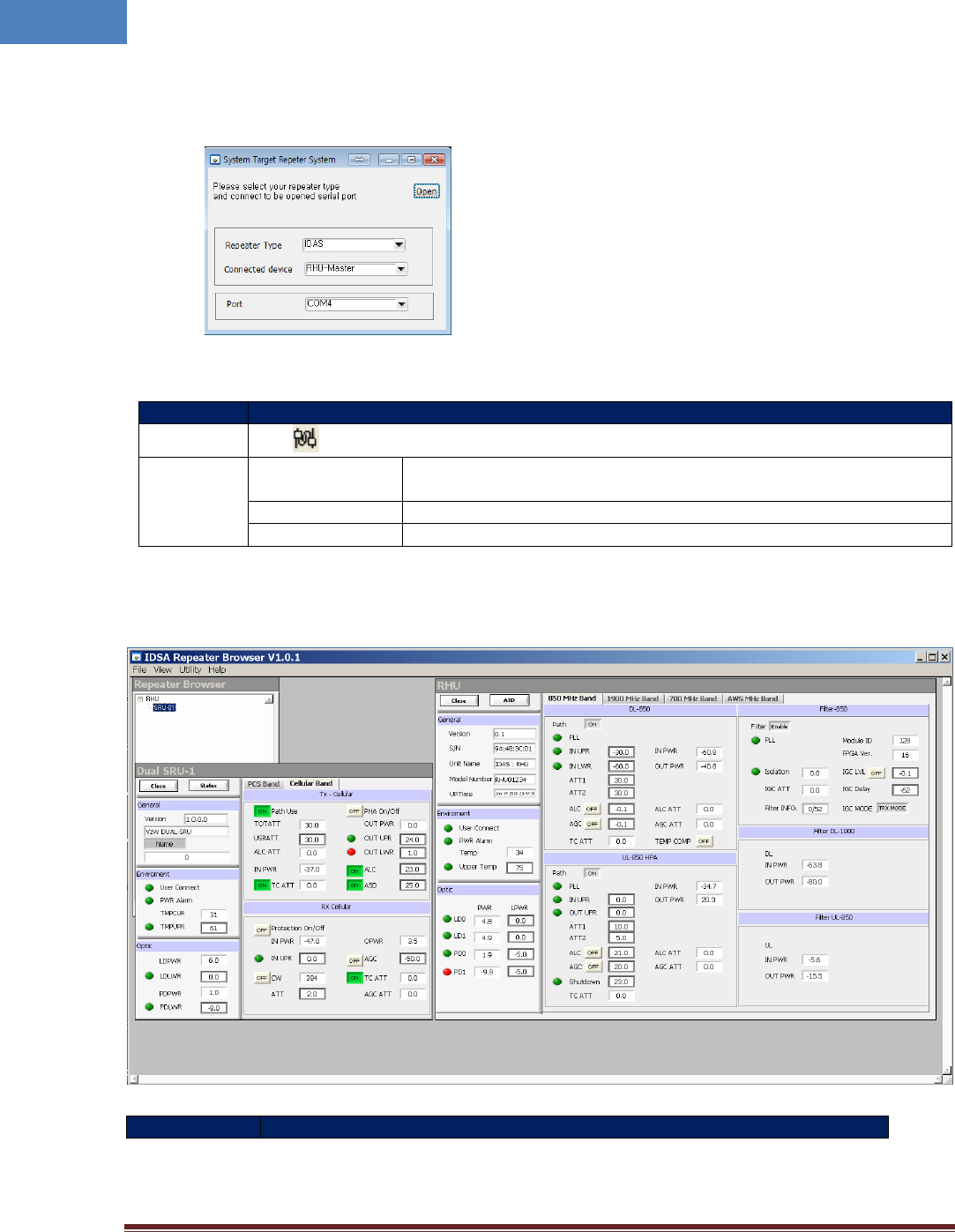
2. After following screen is appeared, please select parameters on this screen as refer to the table
below.
Function
Establishing communication between GUI and repeater
Method
Click button in Menu bar of GUI program
Description
Port
Combo box to select the com port (COM1, COM2, …) which serial port is
set up in Laptop
Repeater type
Select the “iDAS” system
Connected device
Select “RHU-Master” if you want to connect to RHU unit
4.1.4 Main Window of LMT GUI
Section
Description
Intelibs, Inc. Proprietary and Confidential Page 34
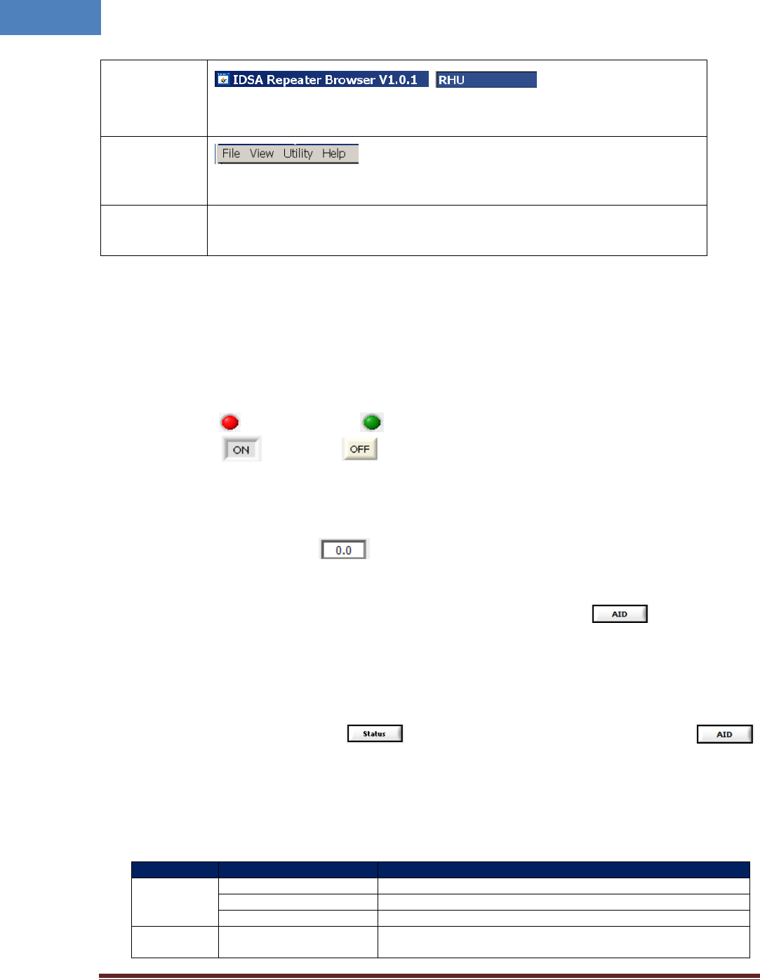
34
Window Title
,
Displays the name and version of management program (GUI)
Displays the type of equipment currently connected to the program (RHU or SRU).
Menu Bar
Presents the working menu for operation.
It is associated with tool icons which can activate the tool bar menus.
Work Space
Status information and control functions are provided with new window screen of
RHU and SRU.
4.1.4.1 Status Display of LMT GUI
Parameters status of each unit are displayed by color of LED’s and values.
LED
Alarm: indicates ALARM, indicates NORMAL
On/Off: means ON, means OFF
Value
Units are not displayed.
Value displayed in box ( )
Control
The texts of controllable LED or values are displayed in BOLD font.
4.1.4.2 Control Policy of LMT GUI
Basically, user can change one item at a time.
Click a controllable item (text, or button)
To go to Control Mode, press button. Then this button will be changed to .
Please “enter” key to confirm the control action after changing any parameter you want to change.
4.1.4.3 Description of Manu bar of LMT GUI
Menu
Sub Menu
Function
File
Connect
Establishes connection between PC (GUI) and DAS unit
Disconnect
Disconnects connection between PC (GUI) and DAS unit
Exit
Finishes the GUI program.
View
Packet Debug
Presents debug packets of communication between DAS unit and
GUI program
Intelibs, Inc. Proprietary and Confidential Page 35
35
Utility
Firmware Download
Downloads compressed firmware file to RHU equipment
Table
Presents RF/Optic power, temperature compensation, Attenuator
table
Help
About
Displays the version information of GUI
4.2 Detail description of Manu bar in GUI
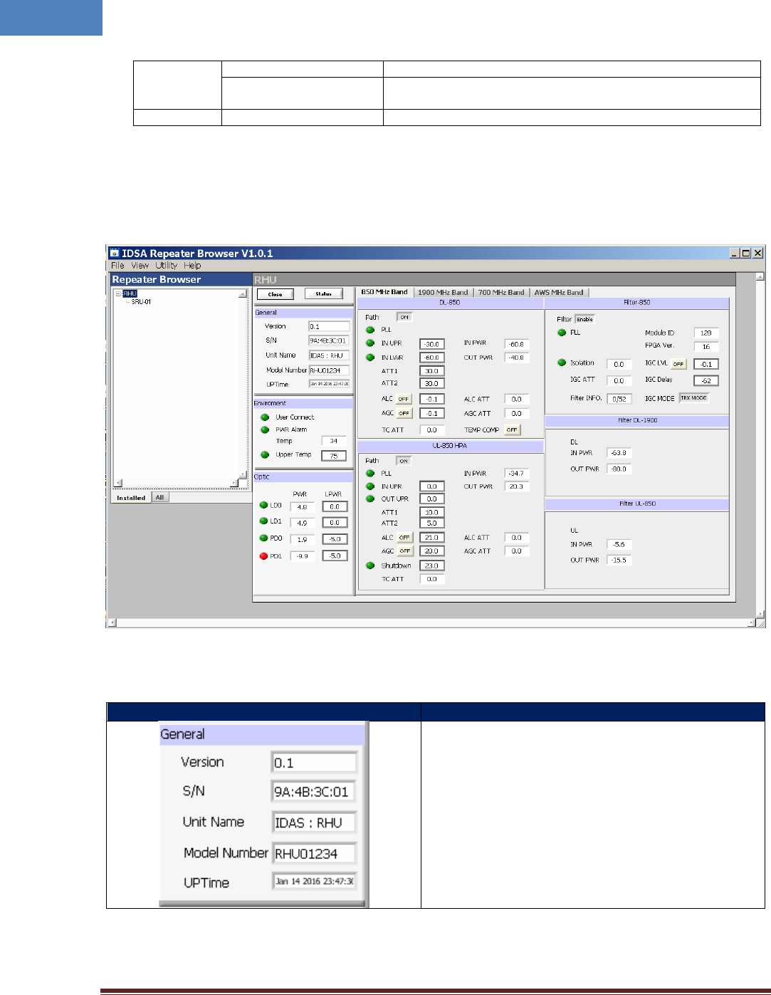
4.2.1 RHU window in GUI screen
4.2.2 Parameters details in RHU window
Group
Description
Version: Firmware Version
S/N: RHU Serial Number
Unit Name: RHU
Model Number: Model number of RHU
Up Time: operating time and date
Intelibs, Inc. Proprietary and Confidential Page 36
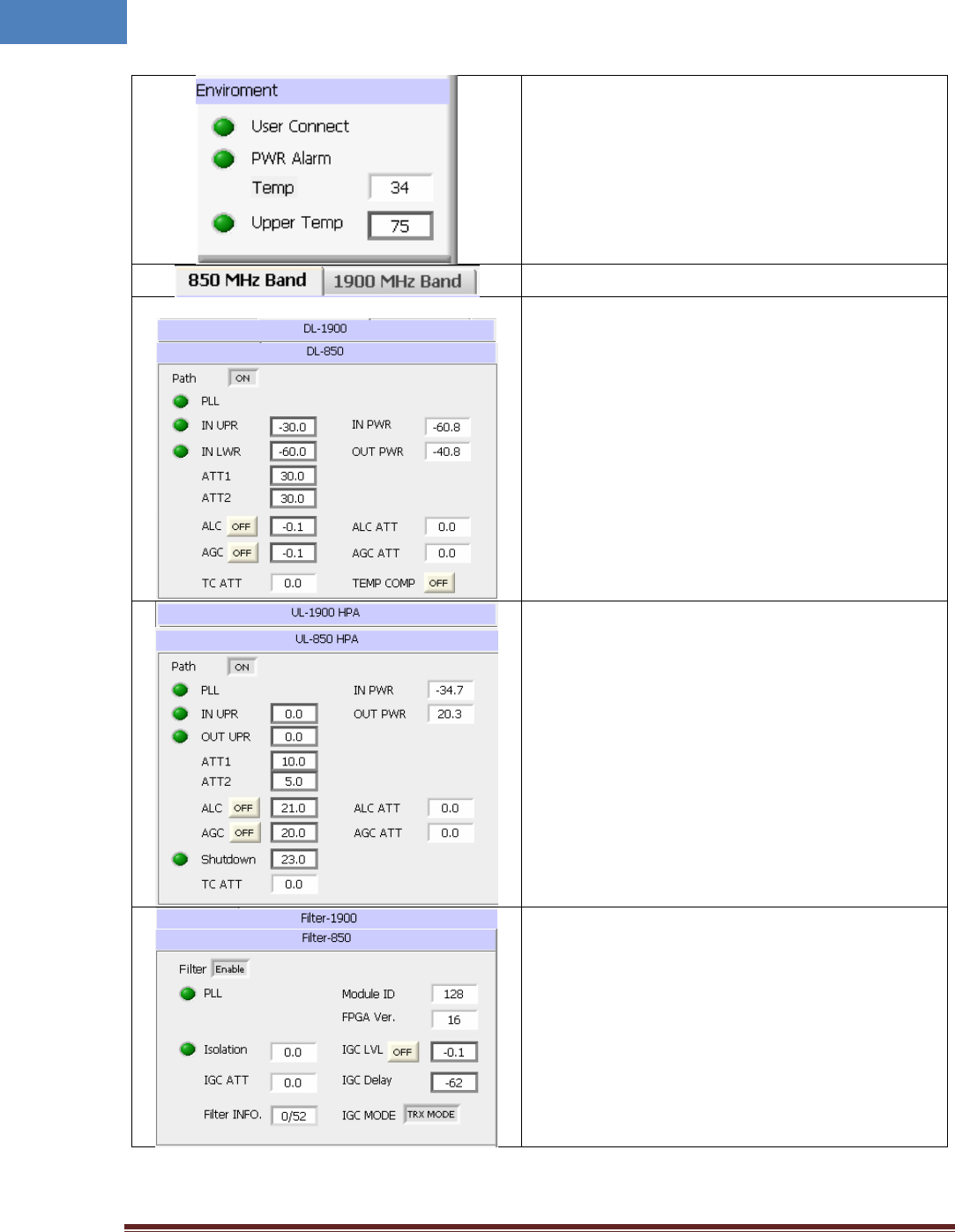
36
User Connect: Connection status between Laptop and
RHU
PWR Alarm: DC power alarm
Temp: Current temperature of unit inside
Upper Temp: set the upper threshold value of
temperature (Value) and alarm status (LED)
Band screen selection TAB.
Path ON/OFF: DL Path ON/OFF function
PLL: PLL lock alarm indicator
IN PWR: DL input power value
OUT PWR: DL Output power value
IN UPR: DL input upper limit value and alarm
IN LWR: DL input lower limit value and alarm
ATT 1 & 2: DL Attenuation value for the DL gain control
ALC: Auto level limit control value and on/off set
AGC : Auto gain control level and on/off set
TC ATT: Temperature compensation Attenuation and
On/Off button
Path ON/OFF: UL Path ON/OFF function
PLL: PLL lock alarm indicator
IN PWR: UL input power value
OUT PWR: UL Output power value
IN UPR: UL input upper limit value and alarm
IN LWR: UL input lower limit value and alarm
ATT 1 & 2: UL Attenuation value for the UL gain control
ALC: Auto level limit control value and on/off set
AGC : Auto gain control level and on/off set
Shutdown: Auto shutdown level value set
TC ATT: Temperature compensation Attenuation and
On/Off button
Filter Enable: Digital filter Enable set
PLL: FPGA PLL lock alarm
Module ID: Digital filter ID information of FPGA.
FPGA Ver: FPGA SW version
Isolation: Isolation margin between two antennas
IGC LVL: Isolation gain control target margin level set
and IGC protection function On / Off
IGC ATT: applied attenuation value by IGC function
IGC Delay: Delay set for IGC function
Filter Info: Digital filter setting information
IGC MODE: IGC control Tx only or Tx/Rx simultaneously
Intelibs, Inc. Proprietary and Confidential Page 37
37
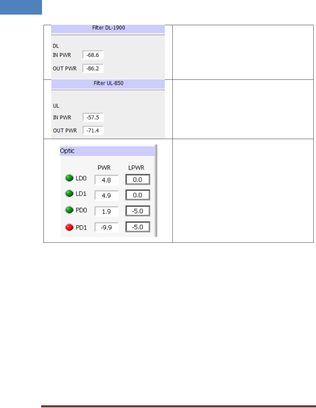
IN PWR: DL input level at digital filter input port
OUT PWR: DL output level at digital filter output port
IN PWR: UL input level at digital filter input port
OUT PWR: UL output level at digital filter output port
LD0: Transmitting LD power level value from Optic1
port
LPWR: Lower threshold value of LD0 power level and
lower alarm status of LD0
LD1: Transmitting LD power level value from Optic2
port
LPWR: Lower threshold value of LD1 power level and
lower alarm status of LD1
PD0: Receiving PD power level value from Optic1 port
LPWR: Lower threshold value of PD0 power level and
lower alarm status of PD0
PD1: Receiving PD power level value from Optic2 port
LPWR: Lower threshold value of PD1 power level and
lower alarm status of PD1
Intelibs, Inc. Proprietary and Confidential Page 38
38
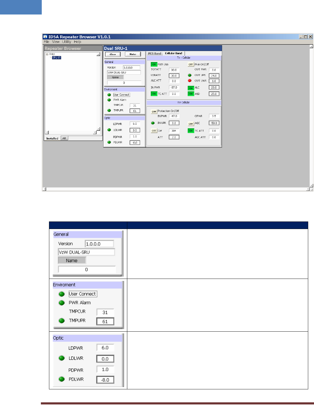
4.2.3 SRU window in GUI screen
4.2.4 Parameters details in SRU window
Group
Description
Version: Firmware version
Type: Type of RU unit
Name: Set the Name, ID, Serial No. of iDAS RU
User Connect: Connection status between Laptop and SRU
PSU: DC alarm status
TMPCUR: Current temperature of SRU inside
TMPUPR: Value/control of upper threshold of temperature (button) and
alarm status (LED)
LDPWR: Transmitted LD power level value
LDLWR: Lower threshold of LD power level and lower alarm status of LD
PDPWR: Received PD power level value
PDLWR: Lower threshold of PD power level and lower alarm status of PD
Intelibs, Inc. Proprietary and Confidential Page 39
39
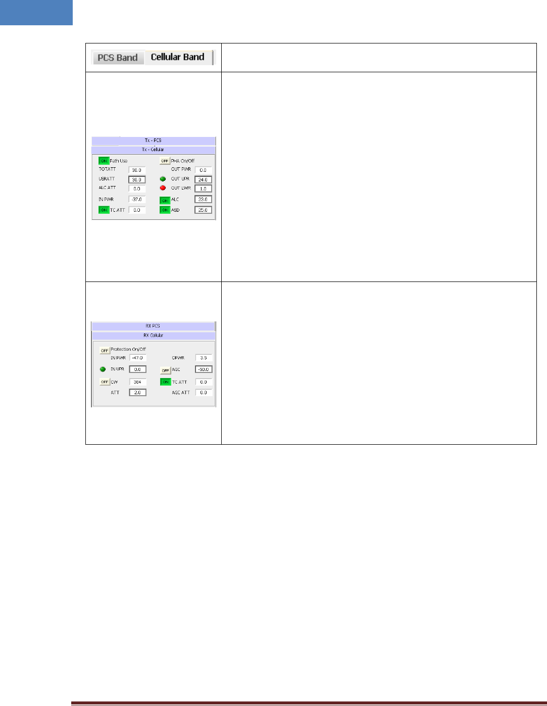
SRU parameter screen selection for PCS/Cellular band TAB.
Path Use: Path use/not use selection
TOTATT: Total attenuation value that is applied to DL path
[TOTATT= USRATT + ALCATT + TCATT]
USRATT: User attenuation set value for user gain set
ALCATT: Attenuation value that controls DL gain automatically to
maintain output level under ALC level when HPA output is higher than
ALC level.
INPWR: Input power level which input to SRU
TCATT: Temperature compensation attenuation value and temperature
compensation Function ON/OFF
HPA On/Off: HPA ON/OFF function
OUT PWR: Transmitting output power level from SRU antenna port
OUT UPR: Output upper threshold level value and alarm
OUT LWR: Output lower threshold level value and alarm
ALC: Auto level limit control threshold value and on/off set
ASD: Auto level shutdown threshold value and on/off set
Protection On/Off: Protection Function ON/OFF to protect SRU from
over input power
IN UPR: UL (Rx) input upper threshold level value and alarm
CW: CH number of pilot signal and ON/OFF function to check UL path
gain budget (Pilot signal power level is -60dBm)
IN PWR: RVS power value at the LNA output point
ATT: User attenuation set value to control UL (Rx) gain
OPWR: UL output power level of SRU
AGC: Auto gain control level value and Function ON/OFF
AGC ATT: Applied attenuation value by AGC function
TC ATT: Applied temperature compensation attenuation value and
function ON/OFF
4.3 Firmware download
Firmware download is performed when system needs to be updated.
Downloading improper images (executable file of repeater CPU) may cause harmful damages to
equipment.
4.4 Additional function of RHU
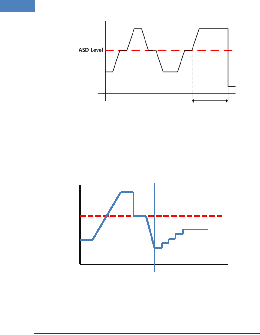
4.4.1 ASD (Auto Shutdown) Function
1. If UL output power level of RHU is above the shutdown level longer than 1 second, RHU
automatically turns off amplifier to protect undesirable transmission.
2. During shutdown state, monitor RU input power. If the level is below 5dB from shut down level,
turns on UL amplifier automatically.
Intelibs, Inc. Proprietary and Confidential Page 40
40
4.4.2 ALC (Auto Limit level Control) Function
1. If UL output power level of RHU reaches the ALC level, RHU decrease the output power to
maintain ALC level automatically.
2. When power level goes down under ALC level, RHU increase output power until ALC ATT is 0 by
500msec ~ 1sec speed.
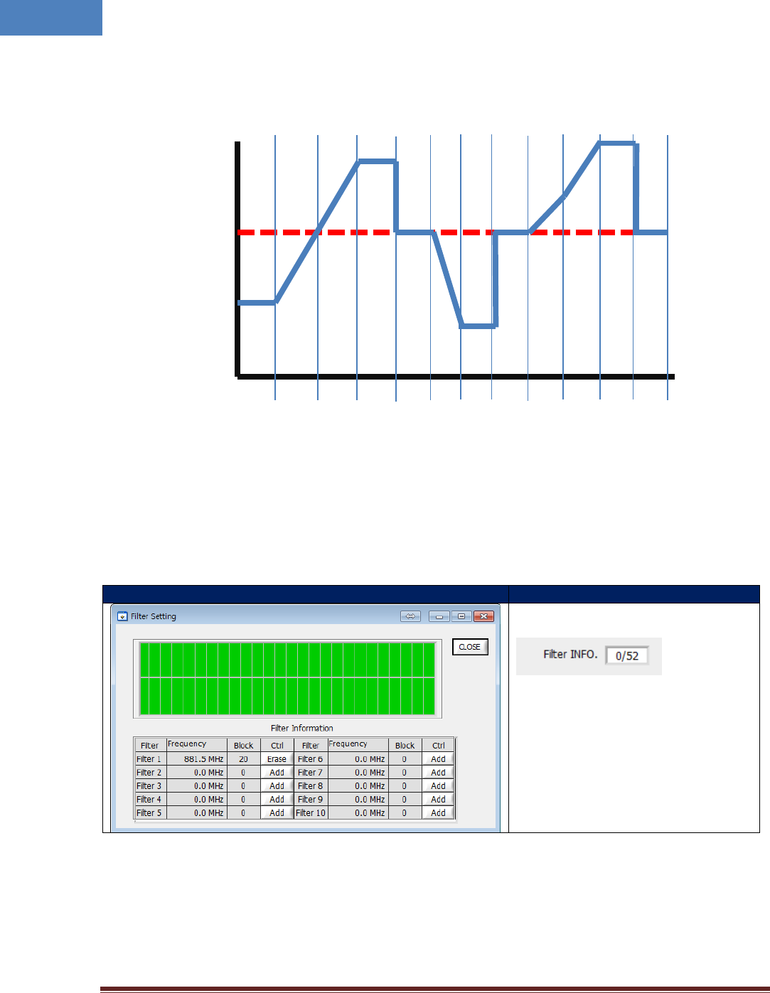
4.4.3 AGC (Auto Gain Control) Function
1. In order to have stable output power, RHU has AGC function that can maintain constant output
power with setting output level.
2. When input level is decreased RHU increase gain to maintain continuous output level, when
ALC
Level
Power
ALC ATT = 0
ALC ATT = δ
decrease
ALC ATT
ALC ATT = 0
Longer than 1 sec, HPA off
Intelibs, Inc. Proprietary and Confidential Page 41
41
input power is increase RHU decrease gain to have same output power automatically.
3. RHU works AGC function by 500msec ~ 1sec speed.
4.4.4 Sub-band selection Function
RHU can select sub-band up to 10 bands in 65MHz bandwidth using digital filter function. These sub-
band filters have very sharp cut-off characteristics and RHU can provide the signal of selected band of
65MHz BW to coverage area. This digital signal processing function also provide input signal information
and antenna isolation information between link and coverage antennas.
Step
Descriptions
If you click “Filter INFO” like following
picture
You can build up band pass filter up to
10 filters.
Input center frequency, number of block
for sub-band and click “Add” button,
sub-band filter is built up.
If you want to erase filter, click “Erase”
button.
ALC
Level
Power
AGC= 0
AGC=δ
AGC= δ
AGC=0
AGC=0
Intelibs, Inc. Proprietary and Confidential Page 42
42
5 Appendix I. Ancillary Devices – Antenna, Cable and other Passive
Device
Intelibs does not provide the ancillary device, however the following or equivalent devices are
recommended:
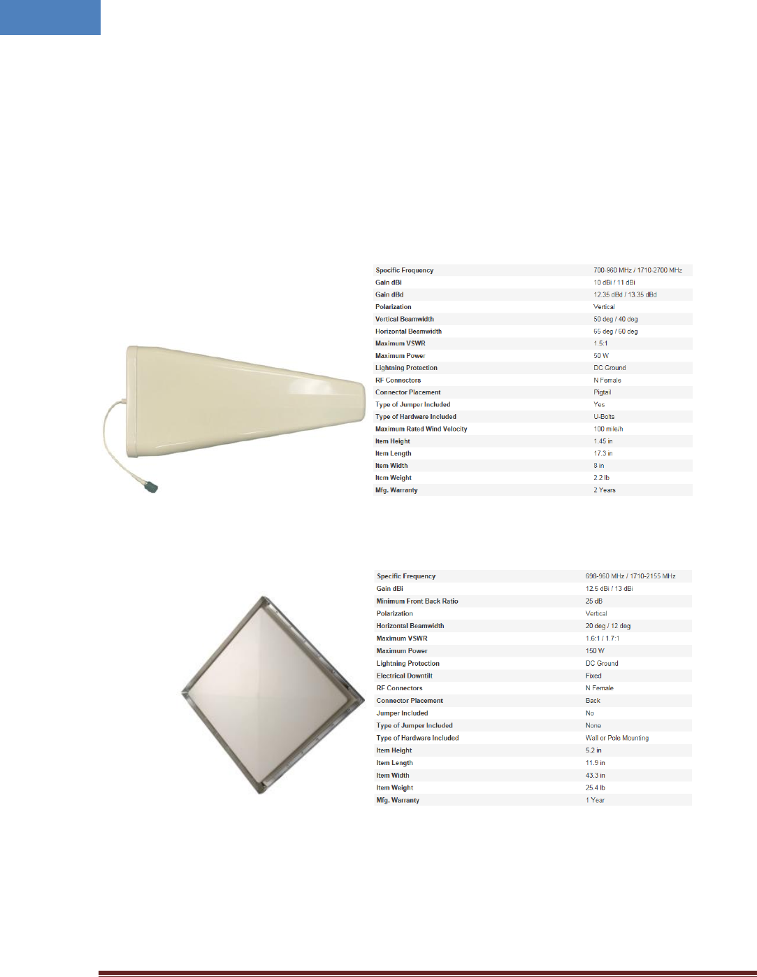
Recommended Antenna:
o Directional Yagi Antenna
o High isolation antenna
Coaxial Cable:
o LDF4, AL4RPV-50 1/2” Plenum Air Aluminum coaxial cable or equivalent coaxial cables
Fiber Cable:
o LC/UPC type signal mode optical cable

Intelibs, Inc. Proprietary and Confidential Page 43
43
6 Human RF Exposure – Maximum Permissible Exposure Evaluation
The recent FCC developed guideline for evaluation of the human exposure to the RF emissions. The
maximum permission Exposure (MPE) for power density of the transmitter operating RF ranges between
300 KHz and 100 GHz. As the Intelibs RHU belongs to the fixed equipment, Analysis has been conducted
to evaluate the MPE from the distance greater than 20 Cm as the fixed equipment required.
Antenna gain is restricted to 1.5W ERP (2.49 W EIRP) in order to satisfy RF exposure compliance
requirements. If higher than 1.5W ERP, routing MPE evaluation is needed. The antenna should be
installed to provide at least 20 cm from all persons to satisfy MPE requirements of FCC Part 2, 2, 1091.
RU transmits far below that FCC power density restricts. FCC defines power output limits at 20 cm
distance for various frequency ranges:
Over 300 MHz to 1.5 GHz the limit is determined by frequency /1500
Above 1.5 GHz the limit is 1 mW/cm^2
The basic equation for determining power density is:
S = PG/4(pie)R^2
Were S is power density , which is mW/Cm^2
PG, the transmitted power from the antenna identified as EIRP (Equivalent Isotropically Radiated Power)
R is the distance of interest from the antenna.
Typical Installation Example:
As the typical height of a floor is assumed as 10foot high, an average person is assumed 6foot high, the
distance from antenna to body is 4 feet (112 cm).
For PCS 1900 band, the maximum power output per carrier is assumed 20dBm. With the assumption of
13dBi antenna gain is used, PG in the equation is equal to 33dBm EIRP.
Using S = PG/4pieR^2
S = 2/(4*3.14)*112^2 = 12.7μW/cm^2
Also worst case with the assumption of minimum distance of 20 cm according to FCC regulation:
S = 2/(4*3.14)*20^2 = 0.4mW/cm^2

Intelibs, Inc. Proprietary and Confidential Page 44
44
Limited Warranty
Intelibs, Inc. (“Intelibs”) offers a standard two year warranty from defects in material and installation. INTELIBS may at any time
exclude from this Agreement any Hardware or Software which (1) has been modified, repaired or serviced by anyone other than
Intelibs’ service staff without the prior written approval of Intelibs, (2) has been subjected to unusual physical or electrical stress,
whether such stress results from accident, neglect, misuse, lightning, failure of electrical power, air conditioning, humidity control,
transportation, the making of specification or configuration changes requested by Customer, or any other cause other than ordinary
use, and whether or not such stress is the fault of the Customer, (3) has been purchased from another Vendor and is networked,
linked, attached or otherwise intended to work with the System or (4) has been moved from the place of installation. When the
system has been improperly modified, repaired, stressed, used or moved as described above, Intelibs may, at its option and subject
to the approval of the Customer, perform such corrective work, including any repairs, replacements and adjustments, as are in
Vendor’s opinion necessary to restore the System to the condition it would have been in if subjected only to normal wear and tear
at the Customer’s expense.

Intelibs, Inc. Proprietary and Confidential Page 45
45
Index
1900 MHz band ................................................ 17
1900 MHz Frequency map ............................... 18
850 MHz band .................................................. 19
850 MHz Frequency map ................................. 19
AC Power specifications ................................... 21
Bluetooth ......................................................... 30
DAS management network .............................. 30
Duplex .............................................................. 26
Link Antenna connection ........................... 25, 26
LMT ............................................................ 30, 31
Local management interface ........................... 30
MU ..................................................................... 6
Optic cable connection .................................... 29
OSP ................................................................... 28
Power cable connection .................................. 27
Rated Input Voltage ......................................... 21
RHU .................................................................... 6
RHU Modules ................................................... 11
RU ...................................................................... 6
SC/APC ............................................................. 28
SNMPv3 ..................................................... 30, 31
Web interface .................................................. 30