T80W Manual
2017-12-08
: Intellian T80W Manual t80W_Manual t80W d
Open the PDF directly: View PDF ![]() .
.
Page Count: 138 [warning: Documents this large are best viewed by clicking the View PDF Link!]

Marine Satellite Television Antenna System
t80W
Installation and Operation User Guide

Serial number of the product
This serial number will be required for the all troubleshooting or service inquiries.
© 2016 Intellian Technologies Inc. All rights reserved.
Intellian and the Intellian logo are trademarks of Intellian Technologies, Inc.,
registered in the U.S. and other countries. t80W, w-Series, and t-Series are
trademarks of Intellian Technologies, Inc. Intellian may have patents, patent
applications, trademarks, copyrights, or other intellectual property rights covering
subject matter in this document. Except as expressly provided in any written license
agreement from Intellian, the furnishing of this document does not give you any
license to these patents, trademarks, copyrights, or other intellectual property.
All other logos, trademarks, and registered trademarks are the property of their
respective owners. Information in this document is subject to change without
notice. Every effort has been made to ensure that the information in this manual
is accurate. Intellian is not responsible for printing or clerical errors.
Doc. No. 2016U1-UM0201-V2_3

INDEX

5
INDEX
INTRODUCTION 9
Intellian t80W Introduction 10
Intellian t80W Features 11
INSTALLING THE ANTENNA 13
System Package 14
Planning the Installation 18
Antenna Installation 22
INSTALLING THE ACU 33
Mounting the ACU 34
Connecting the System Cables 36
PC to ACU Commnunication Setup 40
Wi-Fi Connection 42
OPERATING THE ACU 45
Introduction 46
Normal mode 47
Setup mode 51
Installation Settings 52
Antenna Settings 55
Satellite Settings 66
System Settings 75
Aptus®81
Introduction to Aptus®82
Software Installation 83
PC to ACU Communication Setup 84
Toolbar Menus 87
System Property Status Dashboard 90
Work View Tabs 92
APTUS WEB 109
Introduction 110
Main Page 111
Antenna Settings 115
Firmware & Conguration 121
Administration 127
TECHNICAL SPECIFICATION 137
WARRANTY 138

t80W – Marine Satellite TV Antenna System
6
CERTIFICATIONS
Doc Number IT14-DC0821-02
Intellian Technologies, Inc.
EMEA & APAC Headquarters
348-5 Chungho-Ri, Jinwi-Myeon
Pyeongtaek-Si, Gyeonggi-Do, 451-862 Korea
Tel: + 82 31 379 1000
Intellian Technologies USA, Inc.
US Headquarters
9004 Research Drive
Irvine, CA 92618 USA
Tel: +1 949 727 4498
CE & FCC Declaration of Conformity (DoC)
We, Intellian Technologies, Inc. located at 2F Dongik Bldg., 98 Nonhyun-dong, Kangnam-gu, Seoul 135-080, Korea
declare under our sole responsibility that the product(s) described in the below to which this declaration relates is in
conformity with the requirements of the EU EMC Directive 89/336/EEC and FCC 47 CFR Part 15 Subpart B when the
methods, as described in EN 60945: 2002, ANSI 63.4: 2003 and EN 60950-1:2006+A11:2009+A1:2010+A12:2011,
respectively.
Product Information:
Product Name(s):
Intellian t80, 85cm Ku-band Maritime TVRO Antenna System
Intellian t100, 105cm Ku-band Maritime TVRO Antenna System
Intellian t110, 105cm Ku-band Maritime TVRO Antenna System
Intellian t130, 125cm Ku-band Maritime TVRO Antenna System
Model Number(s):
T3-9XXX, T3-10XXX, T3-11XXX, T3-13XXX
Supplementary Information:
Notified Body Involved:
(Testing Organization)
SK Tech Co., Ltd.
820-2, Wolmoon-Ri, Wabu-Up, Namyangju-Si, Kyunggi-Do, 473-905, Korea
Technical/Compliance
File Held by:
Intellian Technologies, Inc.
348-5 Chungho-Ri, Jinwi-Myeon, Pyeongtaek-Si, Gyeonggi-Do, 451-862 Korea
Authority: Kevin Eom Signature: __ __ ___________
/ CTO, R&D
Date: 21
st
August, 2014

7

t80W – Marine Satellite TV Antenna System
8

9
INTRODUCTION
Intellian t80W Introduction
Intellian t80W Features
INTRODUCTION

t80W – Marine Satellite TV Antenna System
10
Intellian t80W Introduction
The Intellian t80W antenna locks onto satellites quickly and provides seamless
operation in all regions, offering global coverage. The antenna delivers this
performance utilizing a fully stabilized 3-axis platform, as well as a fourth axis for
LNB auto-skew control. In addition, built-in as standard, the internal GPS combined
with Intellian's patented Wide Range Search (WRS®) provides the fastest satellite
acquisition possible. Multiple HD receivers can be connected to the system as
standard, providing a truly hands off global coverage for all regions visited.
The Intellian t80W incorporates the patented WorldView™ LNB (Low Noise Block-
Down Converter), which automatically switches frequency depending on the region
the antenna is operating in; all of the switching information is contained in the
Antenna Control Unit (ACU). As the satellite TV provider is selected electronically,
there is no requirement to purchase multiple LNB modules, recongure complex
systems and manually change the LNB unit inside the antenna dome each time the
vessel crosses into a different satellite service region.
The t80W antenna has a broad elevation range, from -15° to +110°, enabling
operation in all conditions and the cross level axis ensures uninterrupted viewing
even when the antenna is operating near the equator. The t80W dome is designed to
match the v80G VSAT antenna, providing customers with a compact dual antenna
solution for communications and entertainment.
All Intellian antenna systems are designed, manufactured and tested to withstand
the company's industry-leading standards for vibration and extreme shock in all sea
states and weather conditions.

11
INTRODUCTION
Intellian t80W Features
Global Satellite Services Compatibility
Intellian t80W provides boaters with seamless and uninterrupted satellite TV service
across multiple coverage areas and service providers offering cost-effective solutions
and straightforward, simple operation from the Americas (circular polarized), as well
as Europe, the Middle East and the Asia Pacic region (linear polarized) with one
LNB module.
Hands-Free WorldViewTM LNB Module
The WorldViewTM LNB module is built with precise pioneering technology of ±25
kHz (±2.5ppm) stability and is designed to receive multi-band and multi-polarization
satellite TV services around the globe. Therefore, boaters are no longer required to
manually switch out the LNB inside the antenna dome or re-wire the system when
the vessel travels from region to region.
DVB-S2 Digital TV Receptions
Some of the HD TV services have moved to DVB-S2 transmission formats and there
will be more in the future. Thanks to Intellian's groundbreaking DVB-S2 digital TV
technology, now boaters are able to enjoy their favorite Sat TV entertainment at sea,
just like home.
Wide Elevation Range
The wide elevation range from -15° to 110° enables the t80W to have seamless
signal reception while the vessel is traveling near the Equator or Polar Regions.
Global Satellite Library
The t80W includes the pre-programmed global satellite library which allows the
boaters to select the desired satellite while travelling from region to region. Once
the satellite is selected the WorldViewTM LNB module will automatically switch to the
corresponding local frequency to receive the signal.
Dedicated Management Ethernet Port
The Management Ethernet Port on the front of the ACU enables direct and simple
network connection between a PC and the ACU. The management Port supports
DHCP network connection by default, allowing automatic IP congurations and
quick access to Intellian's remote management solution, the Aptus Web software.
Wireless Connectivity and Intellian App
The built-in Wi-Fi enables the ACU to be wirelessly connected and can be turned
on or off. Any kind of wireless devices such as PCs, laptops and smartphones can
be used to connect to the ACU and monitor, control and change the settings of the
system wirelessly. An Intellian App is available for download to access to the ACU
via Wi-Fi and operate the antenna from iPhone, iPad or other network devices.
iPhone and iPad are registered trademarks of Apple Inc.
Intellian Network Devices
Intellian Aptus Web enables connection to the t80W to monitor the real time status
of the connected system. This function provides users with direct connection to
sibling devices allowing an integrated control solution for linking multiple devices.

t80W – Marine Satellite TV Antenna System
12

13
INTRODUCTION
INSTALLING THE ANTENNA
System Package
Antenna Unit
ACU (Antenna Control Unit)
Installation Kit
Planning the Installation
Selection of Antenna Installation Site
System Cables
Power Requirement
Tools Required for Installation
Antenna Installation
Unpacking the t80W Package Box
Antenna Dimensions
Antenna Mounting Templates
Installing the System Cables
Mounting the Radome
RF Cable Connections
Position the Radome
t80W – Marine Satellite TV Antenna System
14
System Package
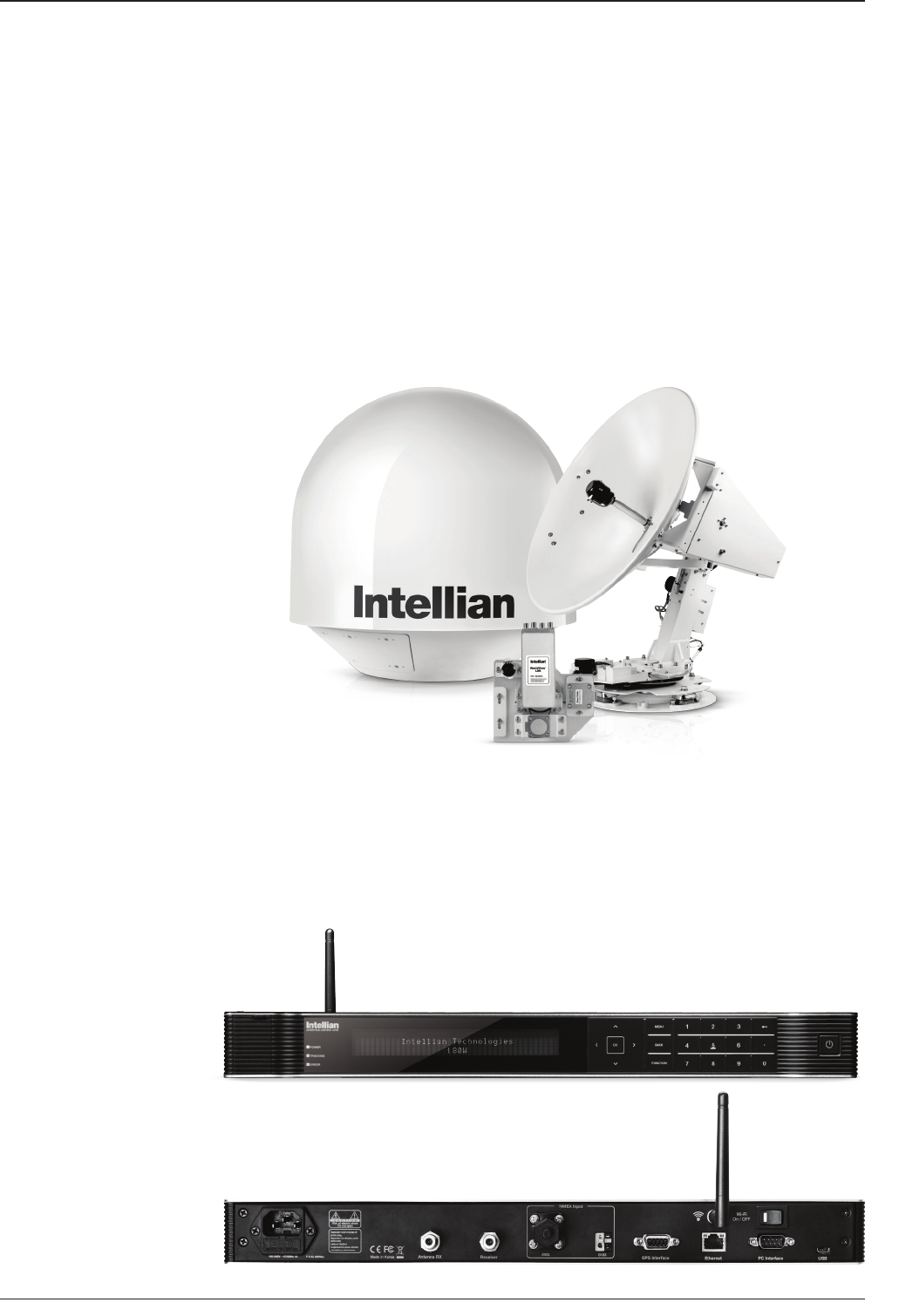
The Intellian t80W consists of two major units, an antenna unit and the antenna
control unit (ACU).
Antenna Unit
The antenna unit includes an antenna pedestal inside a radome assembly unit. The
pedestal consists of the satellite antenna main dish and sub-reector module with
a WorldViewTM LNB module mounted on a stabilized pedestal. The radome protects
the antenna pedestal assembly unit from the severe marine environment.
ACU (Antenna Control Unit)
Antenna Control Unit (ACU) provides the power to the antenna and controls the
various settings of the antenna. Additionally, VFD (Vacuum Fluorescent Display)
allows you to operate the ACU in the dark.
Front panel
Rear panel
15
INSTALLING THE ANTENNA
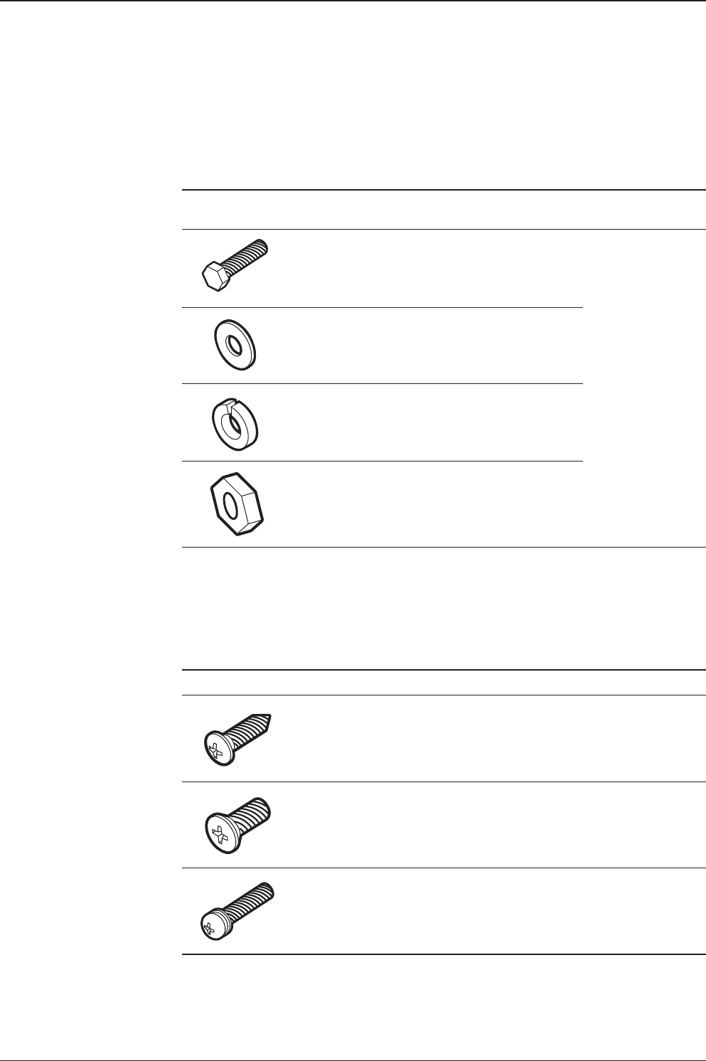
Installation Kit
Contains the items required for mounting the antenna unit and ACU to the vessel.
Antenna Q’ty Description Size Remark
5Hex. Bolt M12 x 80L
Antenna-Deck
5Flat Washer M12
5Spring Washer M12
10 Hex. Nut M12
ACU Q’ty Description Size Remark
5Self-Tapping
Screw ø 4 x 16 Table Mount
Bracket
10 Flat Head Screw M4 x 12L Rack Mount
Bracket ACU
5Sems Bolt M3 x 12L Table Mount
Bracket ACU

t80W – Marine Satellite TV Antenna System
16
Image Q’ty Description Size Remark
1
2
ACU
Bracket
Rack - ACU-19inch Rack
2 Table - ACU-Table
2 1 RG6 Cable
(Optional) 30m ANT - ACU RF Cable
3 1 RG6 Cable 3m ACU - IRD Cable
4 1 AC Power Cable
(CEE 7/7) 1.5m ACU Power
5 1 PC Serial Cable 1.8m ACU to PC
6 1 USB Cable
(A-A) 1.8m ACU to PC
7 2 Rubber Gland RG6 RG6 Cable-Antenna
8 5 Hex Socket
Head Cap M6 x 40L Radome (Top-Bottom)
9 5 Spring Washer M6 Radome (Top-Bottom)
10 5 Flat Washer M6 Radome (Top-Bottom)
11 1 Wi-Fi Antenna 110mm -
Other Components

17
INSTALLING THE ANTENNA
12 1 User Manual -
13 1 Mounting Template -
14 1 USB Flash Drive - -

t80W – Marine Satellite TV Antenna System
18
Planning the Installation
Selection of Antenna Installation Site
Install the antenna in accordance with the following procedures to insure maximum
performance of the antenna.
The antenna should be installed in a place where there is all round clear view of
the horizon. Please be sure there are no obstacles within 15 degrees above the
antenna. Any obstacles can prevent the antenna from tracking the satellite signal
(Refer to the drawing).
Do not install the antenna near by the radar especially on the same plane as the
microwave radar transmissions as these will overload the antenna front-end circuits.
It is recommended to position the antenna at least 4 feet (1.2m) above or below the
level of the radar and minimum of 15 feet (4.6m) away from any high power short
wave radars.
The mounting platform should be robust enough and not subject to excessive
vibration. The movement of the antenna can be minimized by installing at the center
of the vessel. For optimal performance of the antenna, it is not recommended to
install on any corner of the vessel, where the movement of the vessel is the greatest.
Install the bottom of the antenna parallel to the surface of the sea and x tightly to
the structure of the vessel.
Elevation Limit
of Obstacles
Antenna Unit Obstacle
15°

19
INSTALLING THE ANTENNA
System Cables
Before installing the system cables, you need to take the following points into
consideration.
1. All cables need to be well clamped and protected from physical damage and
exposure to heat and humidity.
2. Cable with a tight bend radius should be avoid.
3. Where a cable passes through an exposed bulkhead or deck head, a watertight
gland or swan neck tube should be used.
RF Cable (Customer supplied)
Due to the signal losses across the length of the RF coax on L-Band, Intellian
recommends the following 75 ohm coax cable types for standard system
installations. For cables that run longer than 100 meters, please consult Intellian
Technologies.
Power Requirement
Intellian t80W has been designed to work on a vessel’s power supply rated at 110-220 V AC.
Run Length Coax Type
Up to 35 meters RG6 or LMR-300-75
Up to 60 meters RG11 or LMR-400-75
Up to 100 meters LMR-600-75
Type Multi-conductor, Shielded
Number of wires 2 conductors for NMEA 0183,
5 conductors for NMEA 2000
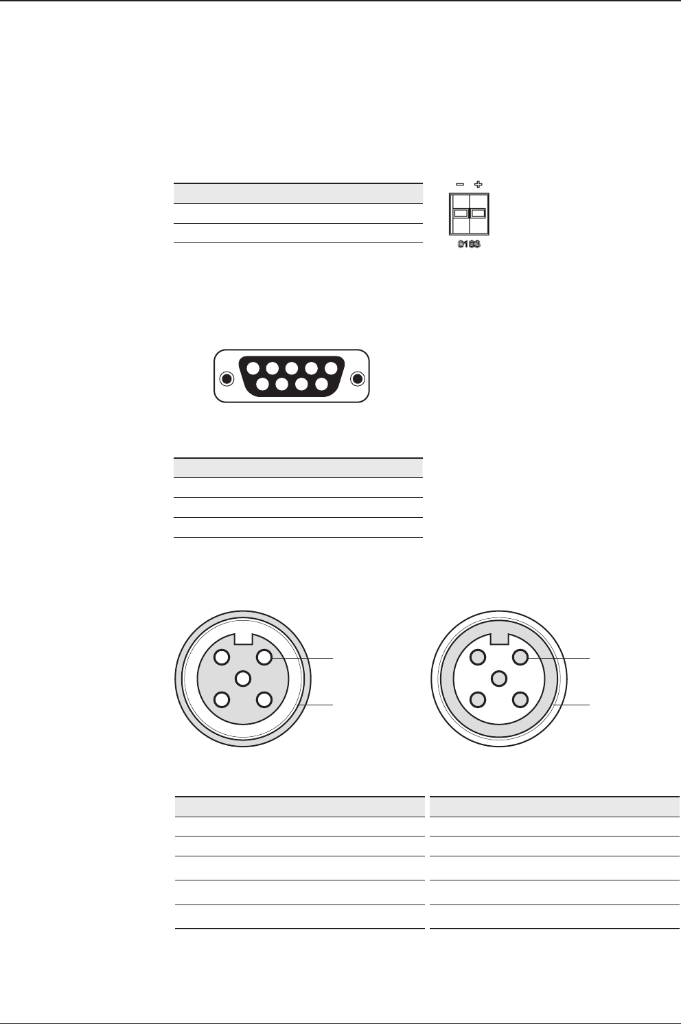
Gyrocompass / GPS Interface Cable (Customer supplied)
t80W – Marine Satellite TV Antenna System
20
5
4
3
21Pins
Connector Threads
5
3
4
12Sockets
Connector Threads
Pin Signal
1Shield
2NET-S, (power supply positive, +V)
3NET-C, (power supply common, -V)
4NET-H, (CAN-H)
5NET-L, (CAN-L)
Pin Signal
1Shield
2NET-S, (power supply positive, +V)
3NET-C, (power supply common, -V)
4NET-H, (CAN-H)
5NET-L, (CAN-L)
Male Connector Female Connector
• NMEA 2000 Connector
12345
6789
54321
9876
Pin Signal
1GND
2GPS OUT +
5GPS IN +
Pin Signal
-NMEA 0183 -
+NMEA 0183 +
ACU GPS In/Out Port
D-Sub 9 pin Female
• GPS Connector
• NMEA 0183 Connector

21
INSTALLING THE ANTENNA
Tools required for Installation
13 mm Spanner
11 mm Spanner
Phillips Head
Screwdriver
Flat Head
Screwdriver (Min. 5mm)
19 mm Spanner5 mm Allen/Hex key
t80W – Marine Satellite TV Antenna System
22
Antenna Installation
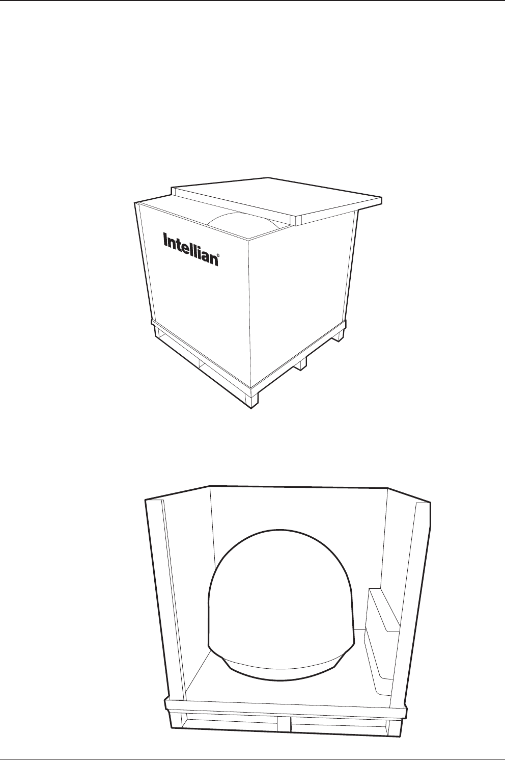
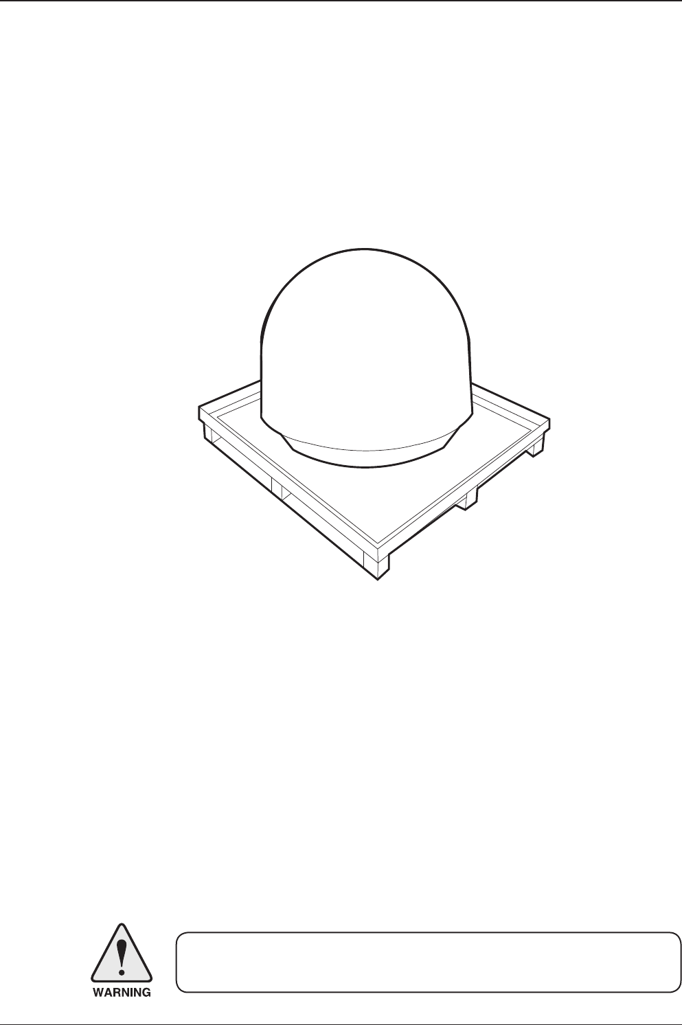
Unpacking the t80W Package Box
Step 1.
Remove the top panel.
Step 2.
Remove ACU box and installation kit box.
23
INSTALLING THE ANTENNA
Step 3.
Remove the 4 shipping bolts that mount the antenna to the pallet.
WARNING: When lifting the antenna by using the lifting strap, ensure to disassemble
the antenna and the pallet.

t80W – Marine Satellite TV Antenna System
24
Step 4.
Open the top radome and remove the red shipping restraints
(3 xing brackets mounted to the antenna pedestal and the azimuth axis).
M6 Flat Washer
M6 Spring Washer
M6 Hex Wrench Bolt

25
INSTALLING THE ANTENNA
Antenna Dimensions
The method of installation and mounting of antenna may vary with vessel design
but the following procedures are applicable in most situations, and will result in a
secure and effective installation. Conrm the height and diameter of the antenna
before installing it.
Radome Dimensions
113 cm (44.5")
12 1c m (47. 5 ” )
t80W – Marine Satellite TV Antenna System
26
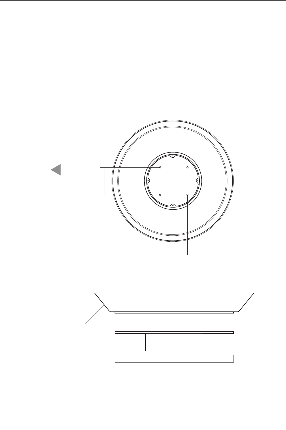
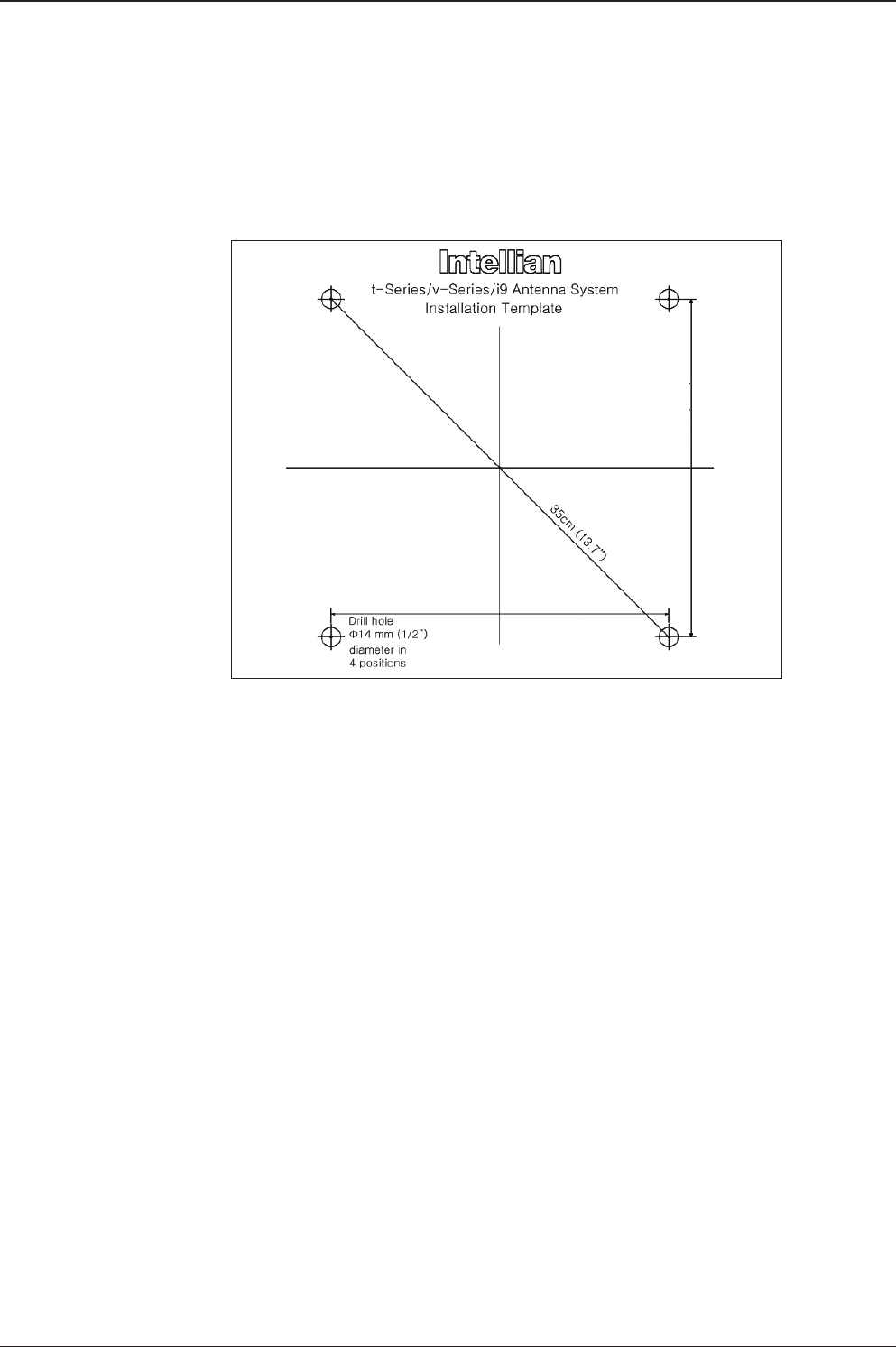
Antenna Mounting Templates
The mounting holes must be in the exact same place as shown in the diagram
below.
Bow direction
52 cm (20.5”)
Radome Bottom
30.4cm (12”)
30.4 cm (12")
24.75 cm (9.74")
24.75 cm (9.74")
27
INSTALLING THE ANTENNA
24.75cm(9.74")
24.75cm(9.74")
t80W – Marine Satellite TV Antenna System
28
Installing the System Cables
The cables must be routed from the antenna through the deck and through various
space on the ship to the antenna control unit. When pulling the cables in place,
avoid sharp bends, kinking, and the use of excessive force.
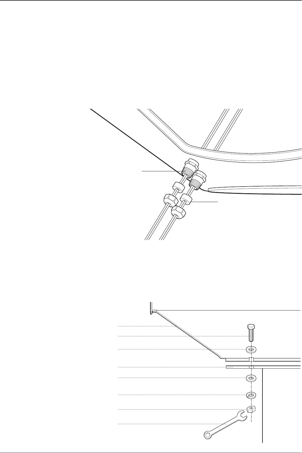
Mounting the Radome
Bolt the radome base directly to the support pedestal. Makesure to use the Intellian
supplied blots from the accessory box when you mount the radome.
Shrinkage Guide
Rubber Gland
M12 Hex. Bolt
Deck
Antenna Unit
M12 Flat Washer
M12 Spring Washer
M12 Hex Nut
M12 Flat Washer
19 mm Spanner
29
INSTALLING THE ANTENNA
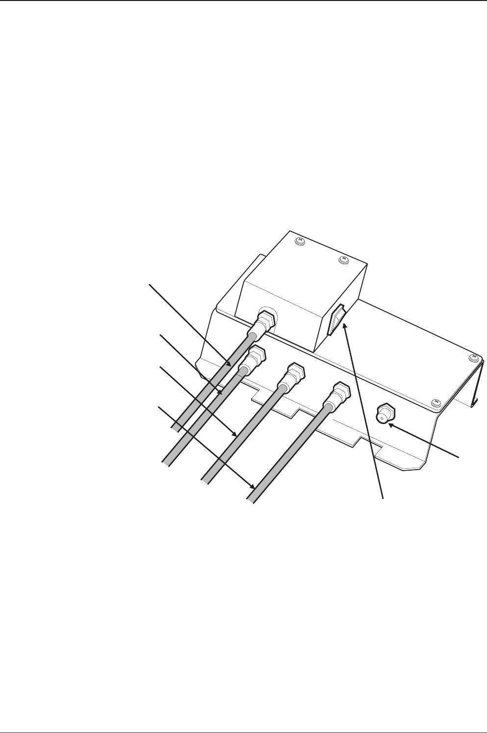
RF Cable Connections
Before installing the RF cable, ensure that the RF cable labeled with RF1 has to be
connected properly between the antenna control unit and the power switch box.
Connect the four RF cables to the RF connectors using an 11mm spanner. Ensure
that the power switch is off during the installation period. When all the hardware
and cables have been installed, turn on the power switch. Use RG11 rubber gland
if you’re using RG11 cable instead of RG6 cable.
RF 1 Cable
RF 2 Cable
RF 3 Cable
RF 4 Cable
Spare
Power Switch
t80W – Marine Satellite TV Antenna System
30
WARNING: Please ensure that your Intellian system is ALWAYS powered ON upon
leaving the dock. Failure to follow these instructions could result in damaging mechanical
parts in the antenna and/or possibly void your warranty. Intellian strongly recommends
to restrain the antenna pedestal properly while underway when power is removed from
the antenna. The normal operating condition for the t80W is to remain powered up at
all times.
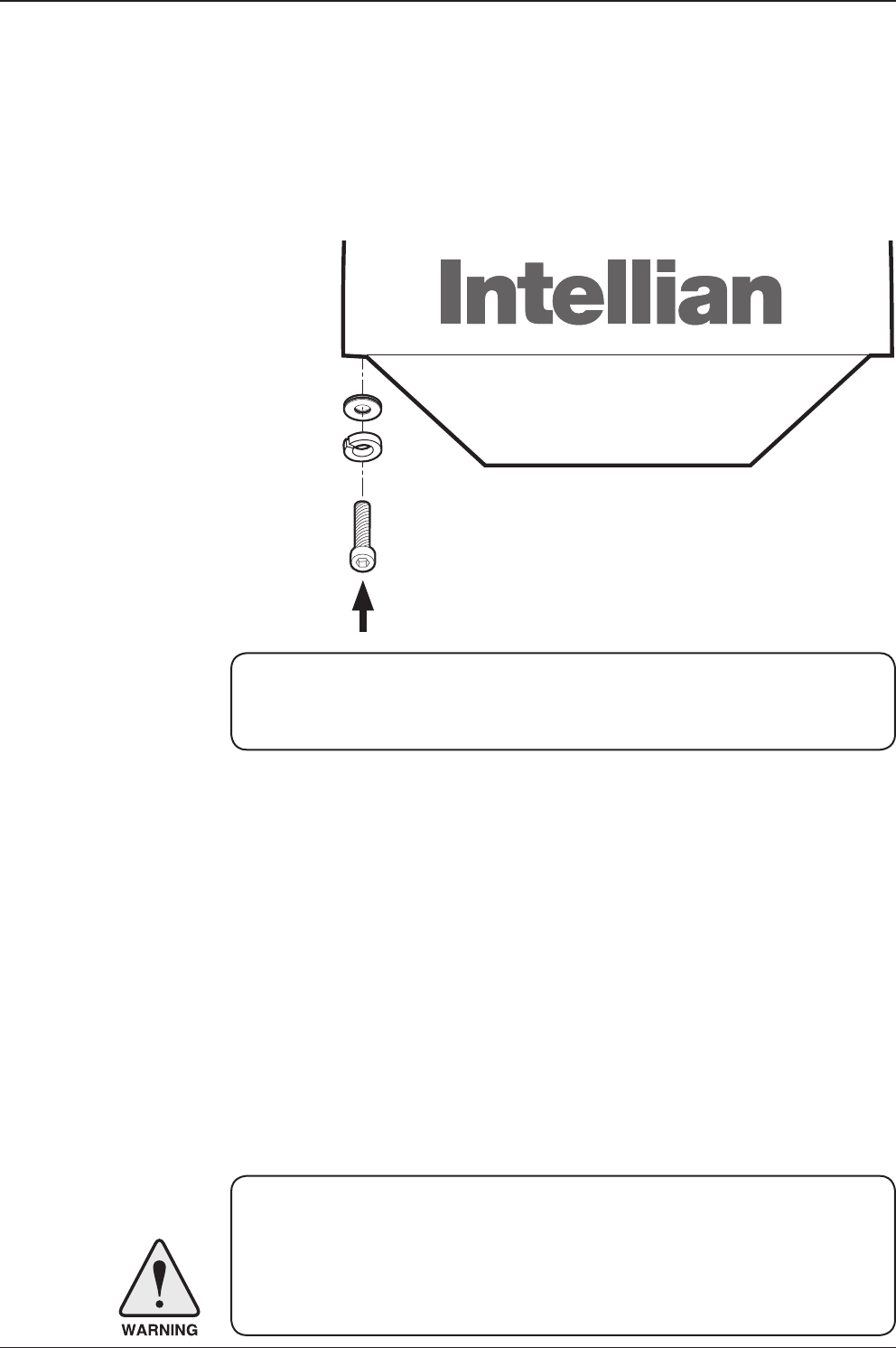
Note: Make sure to use the Intellian supplied bolts from the accessory box when
you reinstall the top radome. Apply Loctite #262 or equivalent to the bolt thread,
and fasten it to a torque setting of 3.5Nm.
Reinstall the top radome.
M6 Flat Washer
M6 Spring Washer
M6 Hex Wrench Bolt
31
INSTALLING THE ANTENNA
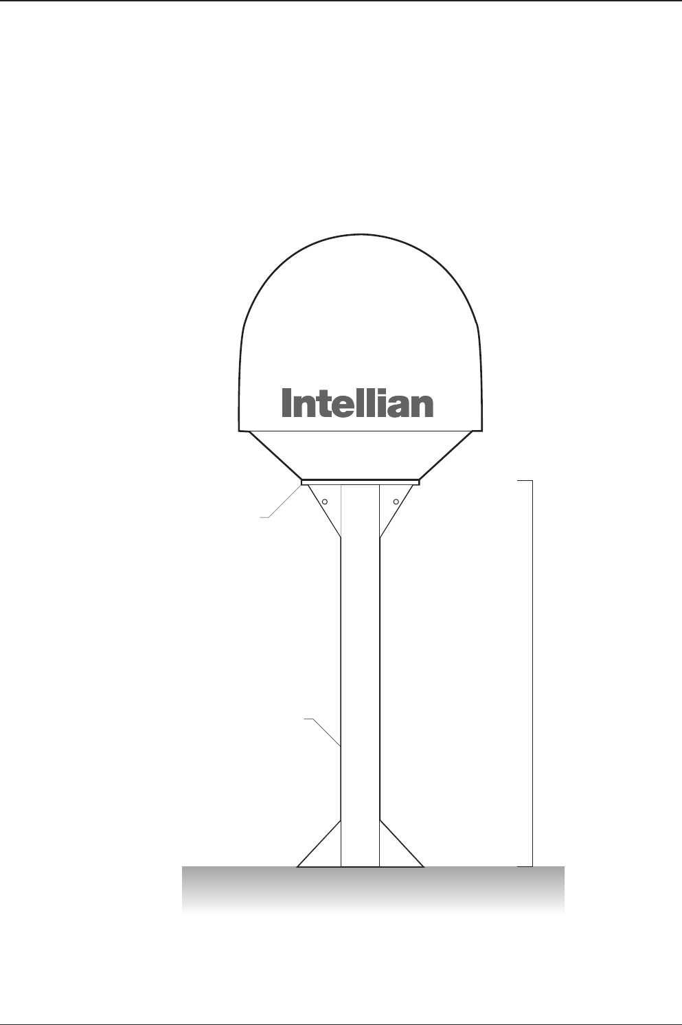
Position the Radome
The radome should be positioned with the BOW marker aligned as closely as
possible to the ship’s centerline.
Recommended size of the
support pedestal
Base Panel
Min 120cm(47”)
Base Panel
Min 0.8cm(0.3”)
Max 1.2cm(0.5”)
Supporting Pole
Appr Ø25.4cm(10”)

t80W – Marine Satellite TV Antenna System
32

INSTALLING THE ACU
Mounting the ACU
19” Rack Mount Type
Table Mount Type
ACU Dimensions
Selection of ACU Installation Site
Connecting the System Cables
Up to 4 Receivers Connection
Multi-Switch Connection
PC to ACU Commnunication Setup
Wi-Fi Connection
t80W – Marine Satellite TV Antenna System
34
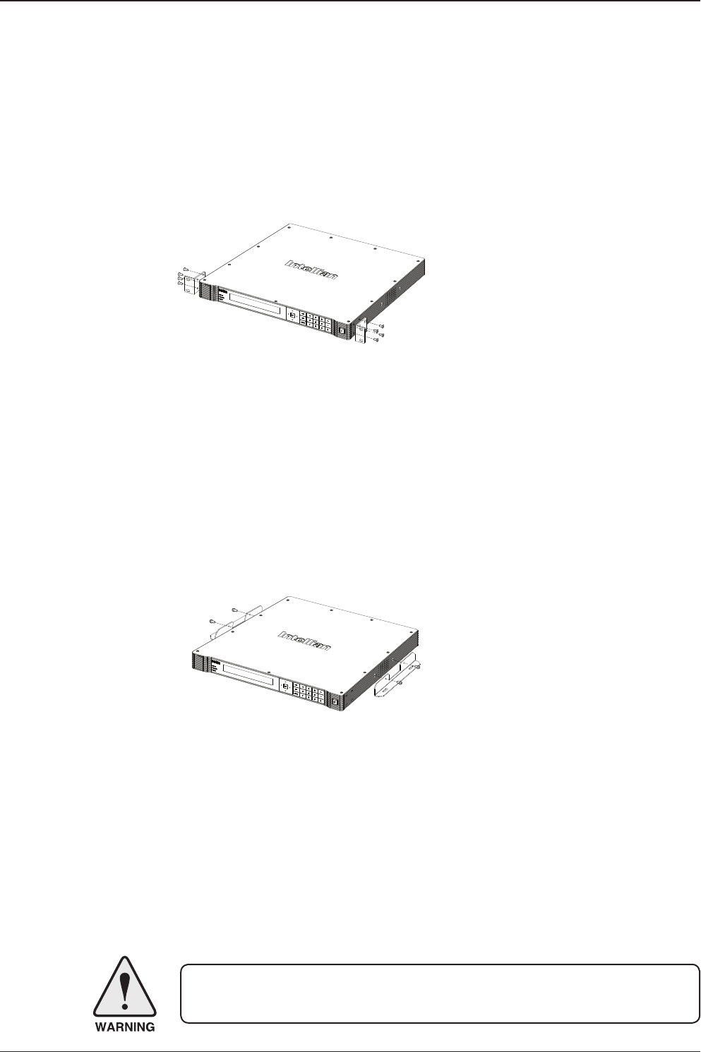
Mounting the ACU
Intellian supplies two types of mounting methods (a) 19” Rack Mount Type and (b)
Table Mount Type to mount your ACU.
(a) 19” Rack Mount Type
- The ACU should be installed using the two supplied Rack Mounting Brackets
which allow ACU to be installed in the 19” rack (Customer Supplied).
- Using the bolts supplied, attach the mounting brackets to the sides of the ACU.
- Place the ACU in the 19" rack.
- Connect the cables to the rear of the ACU.
(b) Table Mount Type
- The ACU should be installed using the two supplied Table Mounting Brackets
which allow for a top or bottom mounting conguration.
- Using the bolts supplied, attach the mounting brackets to the sides of the ACU.
- Place the ACU in the location where it is going to be installed.
- Using a pencil to mark the 4 hole positions (2 on each side), and x the ACU using
the self-tapping screws.
- Connect the cables to the rear of the ACU.
WARNING: Ensure that the cables connected to the ACU are long enough to prevent
damage when the ACU is pulled out from the rack.
Figure 01. 19" Rack Mount Type
Figure 02. Table Mount Type
35
INSTALLING THE ACU
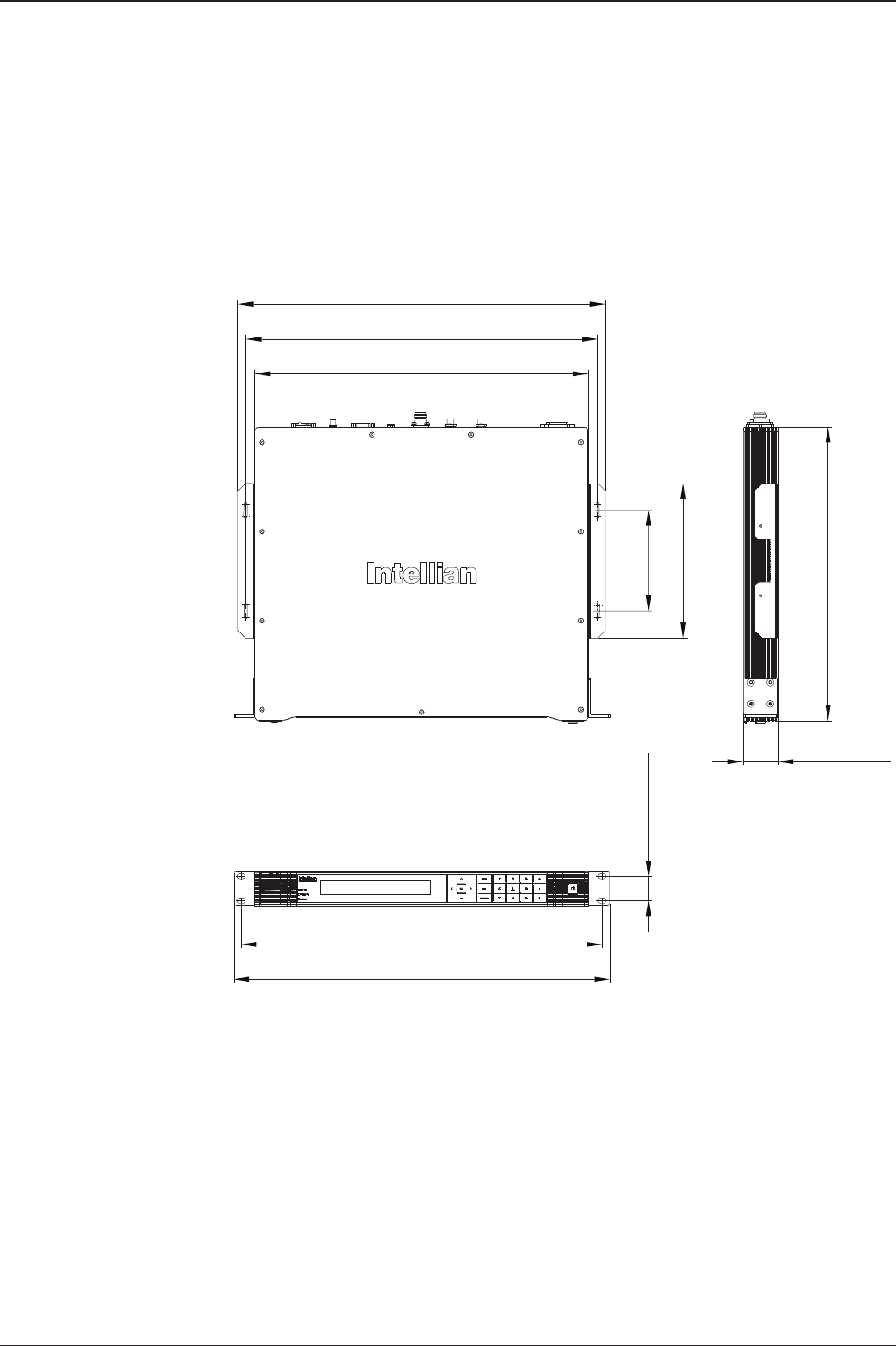
Figure 03. Dimension of ACU
Selection of ACU Installation Site
• The ACU should be installed below deck, in a location that is:
• Dry, cool, and ventilated.
• Easy accessible from your main TV viewing area.
ACU Dimensions
13.0 cm (5.1")
43.1 cm (17")
45.5 cm (17.9")
47.5 cm (18.7")
20.0 cm (7.9")
46.6 cm (18.4")
3.2 cm (1.3")
48.5 cm (19.1")
4.4 cm (1.7")
38.0 cm (15")
t80W – Marine Satellite TV Antenna System
36
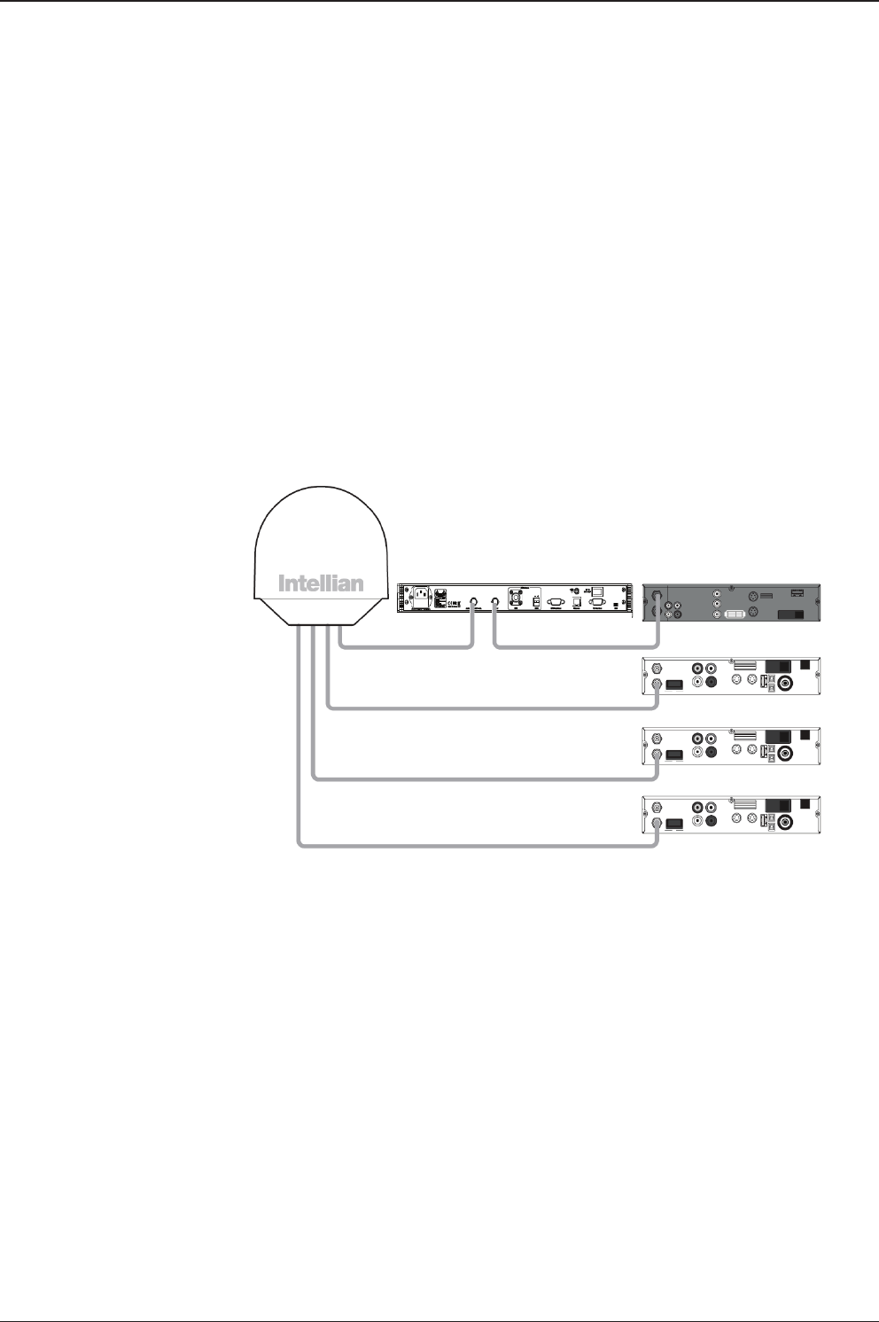
Connecting the System Cables
For your satellite TV system to work properly, the system will have to be properly
connected with all of the provided components, as shown in the gure below.
Separate purchase of a satellite receiver, multi-switch, and TV is required.
Up to 4 Receivers Connection
In Universal LNB mode, RF1, RF2, RF3 and RF4 can be connected, however,
when you switch and use the system from universal LNB mode (ex. Europe) to
single LNB mode (ex. US), RF3 and RF4 will not work and only RF1 and RF2 will
transfer the satellite's signal.
• Connect the RF cable from the ACU's RF1 connector on the power switch box
located inside of the radome to the ANT. RF1 connector on the ACU.
• Connect the RF cable from the RECEIVER connector on the ACU to the RF
connector on the IRD.
• Connect the ship’s gyro to the Gyrocompass Input on the ACU.
• Connect the power cable from the AC power connector on the ACU to a
power source at 110- 220 V AC.
• Press the POWER ON switch on the ACU to start the operation of the antenna
system.
Figure 04. t80W System Diagram
ACU
RF1
RF2 (Optional)
Receiver 1
Receiver 2
Receiver 3
Receiver 4
RF3 (Optional)
RF4 (Optional)
37
INSTALLING THE ACU
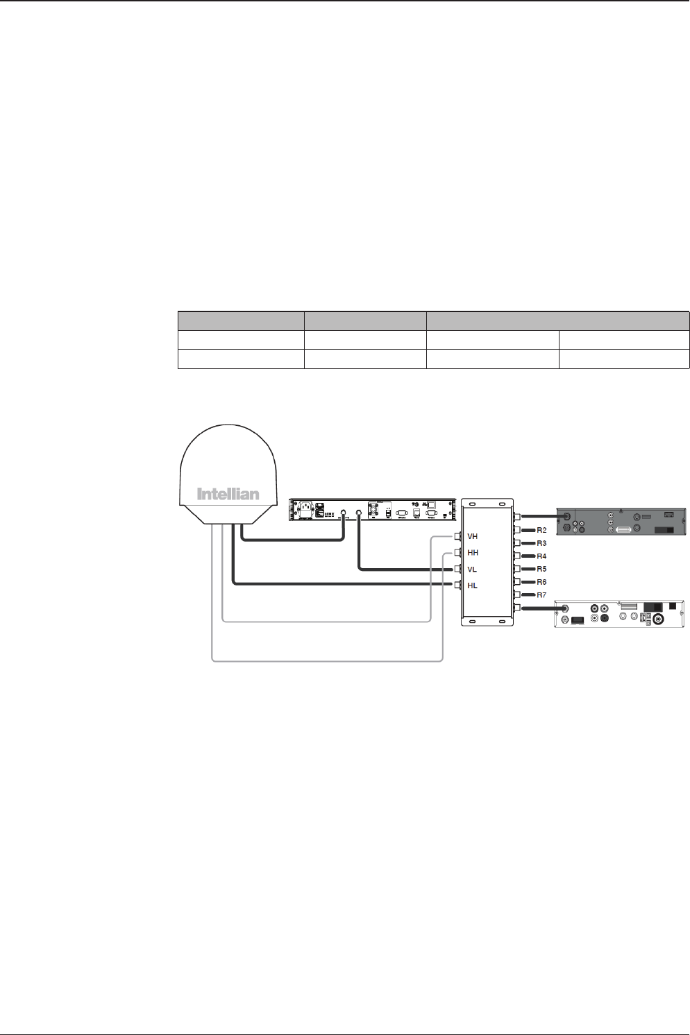
Multi-Switch Connection
When you use the multi-switch in single LNB mode, you need to connect RF1 and
RF2 to the low-band (Horizontal Low and Vertical Low) outputs of the 4x8 multi-
switch and disable DisEqC function while connecting to a receiver other than a
European receiver. In Universal LNB mode, RF1~ RF4 can be connected to any
4 outputs of 4x8 multi-switch. However when you use the system for single LNB
mode, RF3 and RF4 ports will not transfer the RF signal.
RF1 RF2 RF3/RF4
13V 18V 13V+22kHz 18V+22kHz
Vertical Low Horizontal Low Vertical High Horizontal High
RF1
ACU
RF2
RF3
RF4
4x8
Multi Switch
Receiver 8
Receiver 1
Figure 05. Multi-switch Conguration
t80W – Marine Satellite TV Antenna System
38
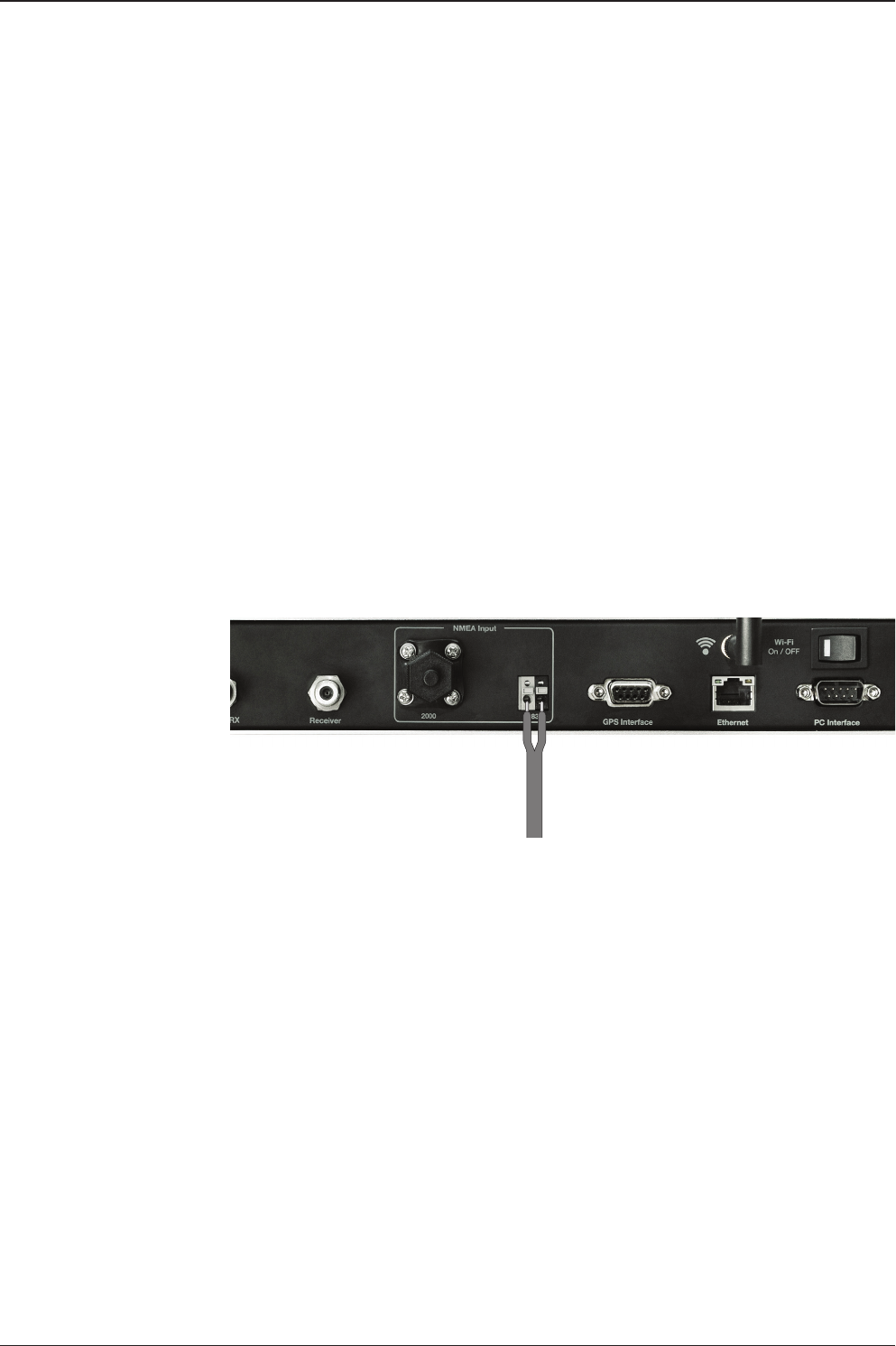
Gyrocompass Connection
For optimum satellite tracking, you must connect a Gyrocompass to the antenna
system through the gyrocompass interface on the rear of the ACU. If the ship’s gy-
rocompass output is other than NMEA 0183 and NMEA 2000 a separate purchase
of an NMEA converter is required.
Recommended Cable
• NMEA 0183 Gyrocompass Interface Cable (Customer supplied)
• Connector Type: 2 conductors for NMEA 0183, 5 conductors for
NMEA 2000
• NMEA heading sentence: xx HDT (4800 Baud, 8, N,1) If there is no HDT
sentence then use HDM sentence instead.
• NMEA 2000 heading PGN Number = 127250 (Vessel Heading)
Figure 06. Gyrocompass Connection
Strip the cable back 5mm (0.2")
Do not solder the cable

39
INSTALLING THE ACU
Connecting the System without a Ship’s Gyrocompass
For a vessel where the ship’s gyrocompass is not installed or is difcult to be
connected, the Intellian Gyro-Free satellite search function will be automatically
enabled to allow the antenna to lock onto the desired satellite without requiring an
external heading input.
The table below provides an example of the Gyro-Free satellite search algorithm.
The Search 1 or Search 3 satellite search pattern will be triggered according to the
existence of heading input and the setting of the heading device.
Search 1: This mode is entered from Search 1 or Search 3. The antenna will search
for the target satellite by turning its azimuth angle in CW(Clockwise) and
CCW(Counter Clockwise) direction in a turn rotation until the antenna
receives the lock signal from the receiver or the DVB(Digital Video
Broadcasting) transponder of the target satellite is decoded by the
antenna.
Search 2: The antenna will search for the target satellite by turning in a two-axis
pattern consisting of alternate movements in azimuth (AZ) and elevation,
until the antenna receives the lock signal from the receiver or the DVB
transponder of the target satellite is decoded by the antenna.
Search 3: The antenna will search for the target satellite by turning its azimuth angle
directly to the position calculated using the ship’s heading input and lock
onto the satellite.
* Search 1 and Search 2 will enter to Search 3 mode once the desired signal
is found.
Quick Setup Procedure
• Set the satellite with DVB transponder as the target satellite.
• Set “No Device” to the heading device.
• The antenna will search for the target satellite by turning its azimuth angle in CCW
direction and lock onto the satellite signal until the antenna receives a lock signal
from the receiver or the DVB transponder of the target satellite is decoded.
• Set the heading device as NMEA.
• Enter “Manual search” menu and touch “Function” key to save the current settings.
Intellian ACU will automatically calculate and save the bow offset.
• Upload the real TARGET satellite pre-congured from the library.
Setting of Heading Device
Existence of Heading Data No Device
NMEA / NMEA 2000
Ground Test
With Heading Data Search 1 Search 2 Search 2
Without Heading Data Search 1 Search 1 Search 2
t80W – Marine Satellite TV Antenna System
40
PC to ACU Communication Setup
You can establish data communication between a PC and the ACU using one
of the following methods.
TCP/IP Connection
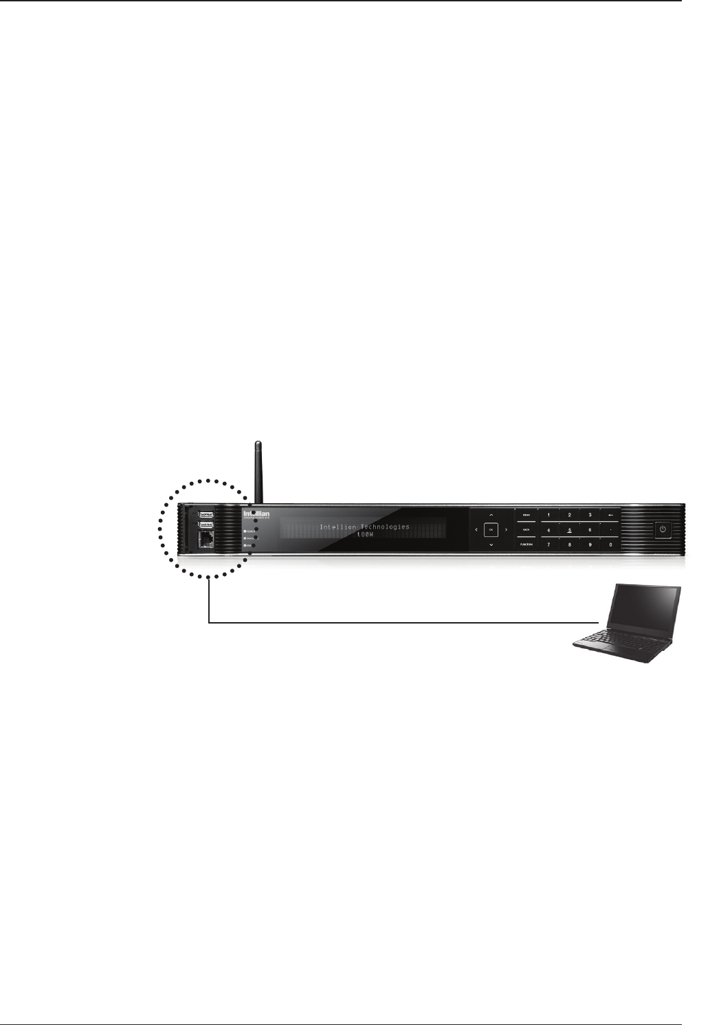
Connection through Front Panel Management Port
This method is most recommended. The network is automatically congured by
DHCP without the need of additional PC IP conguration.
1. Connect an Ethernet cable from a PC Ethernet port to the Management port
on the front of the ACU.
2. Network connection is established.
3. Use the following IP address to access Intellian Aptus® or Aptus Web page.
• 192.168.2.1 (Default)
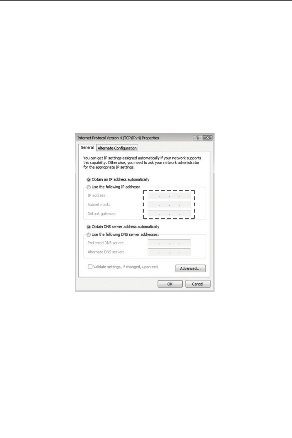
Connection through Rear Panel Ethernet Port
This method requires separate IP conguration on a PC.
1. Connect an Ethernet cable from a PC Ethernet port to an available LAN port
of a Switch/Hub.
2. Go to Control Panel > Network and Sharing Center > Change Adapter Settings
and right-click on the Local Area Connection then click Properties
3. Select TCP/IPv4, then click Properties.
4. Change the network settings on a PC;
• IP: 192.168. 0.222 (Secondary: 10.10.1.2)
• Subnet Mask: 255.255.255.0
• Gateway: 192.168.0.223 (Secondary: 10.10.1.1)
5. Use the following IP address to access Intellian Aptus® or Aptus Web page.
• Default: 192.168.0.223 (Secondary: 10.10.1.1)
PC
Management
Ethernet Port
Ethernet Port

41
INSTALLING THE ACU
Serial/USB Connection
Connection through Serial Port
1. Connect a 9-pin Serial cable from the PC INTERFACE connector on the
ACU to the 9-pin serial port on your PC.
2. If there is not a 9-pin serial port on the PC, use a USB-Serial adapter.
Connection through USB Port
There are two USB(USB-to-Serial) ports are available on the ACU. One is on the
front and the other is on the rear.
1. Connect a USB cable from a USB port on your PC to the USB port
on the ACU.
Serial Connection
USB Connection
Note: The t80W also supports Wi-Fi connection between a PC and the ACU.

t80W – Marine Satellite TV Antenna System
42
Wi-Fi Connection
1. Turning on the Wi-Fi switch
Turn on the switch on the back of the ACU, and 30 seconds after enabling the
power supply, conrm if a red light appears on the switch.
Setup Wi-Fi Connection
• Setting up the ACU in order to access Wi-Fi
• Setting up the PC (AP Mode) in order to access Wi-Fi
• Remote Aptus Web Conrmation
Setting up the ACU in order to access Wi-Fi
43
INSTALLING THE ACU
2. To manually change the network settings, click on "Use the following
IP address" and use the settings listed below.
Case #1
If iARM Module’s IP is known
The iARM module’s default IP is 192.168.1.223
PC IP : 192.168.1.222
Subnet Mask : 255.255.255.0
GateWay : 192.168.1.223
Case #2
iARM Module’s IP is unknown
The iARM module’s secondary IP is 10.10.10.1
PC IP : 10.10.10.2
Subnet Mask : 255.255.255.0
GateWay : 10.10.10.1
Setting up the PC in order to access Wi-Fi
1. Setting up my computer’s wireless IP address
- Control Panel> Network and Sharing Center > Change Adapter Settings >
Right click on the “Bluetooth Wireless Connection”> Click Properties
After selecting TCP/IPv4, click on the properties menu, then select "Obtain an IP
address automatically."
t80W – Marine Satellite TV Antenna System
44
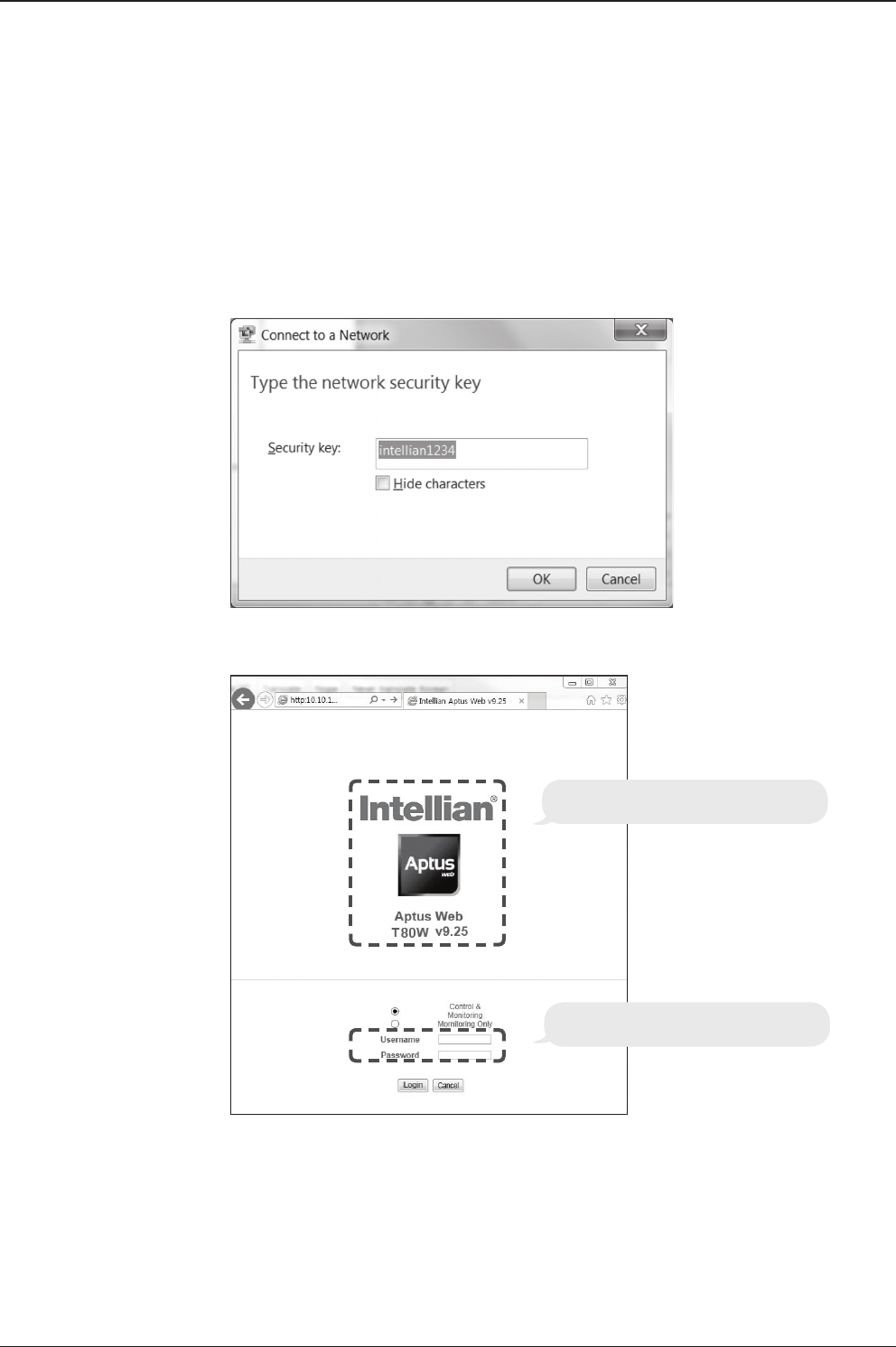
3. Connect Wi-Fi in AP mode.
After clicking on the Windows Wireless Connection icon, click on intellian-TVRO
(Default).
4. Enter the Network Security Key.
Key: intellian1234 (Default)
Login by entering the ID / Password listed below.
Username: intellian (Default)
Password: 12345678 (Default)
6. When you login, make sure that all the data within every page is being displayed
correctly.
5. You can conrm the logo and version data by accessing http://192.168.1.223
Aptus Web v X.XX
Login intellian / 12345678

OPERATING THE ACUOPERATING THE ACU
Introduction
Normal Mode
System Startup
Change of Target Satellite
Monitoring Current Status
Setup Mode
Installation Settings
Installation
Antenna Settings
Setting Antenna Manual Search
Setting Antenna POL. Angle
Setting Antenna Search Parameter
Setting Antenna Parameters
Executing Antenna Diagnosis
Satellite Settings
Setting the Satellite Pair
Edit Satellite Information
Setting the Region
Finding Transponders
System Settings
Setting Location
System Management
Key Lock
t80W – Marine Satellite TV Antenna System
46
This section of the handbook describes how to set up your Satellite TV System after
installation using the ACU.
Introduction
WARNING: Please ensure that your Intellian system is ALWAYS powered ON upon
leaving the dock. Failure to follow these instructions could result in damaging mechanical
parts in the antenna and/or possibly void your warranty. Intellian strongly recommends
to restrain the antenna pedestal properly while underway when power is removed from
the antenna. The normal operating condition for the t80W is to remain powered up at
all times.
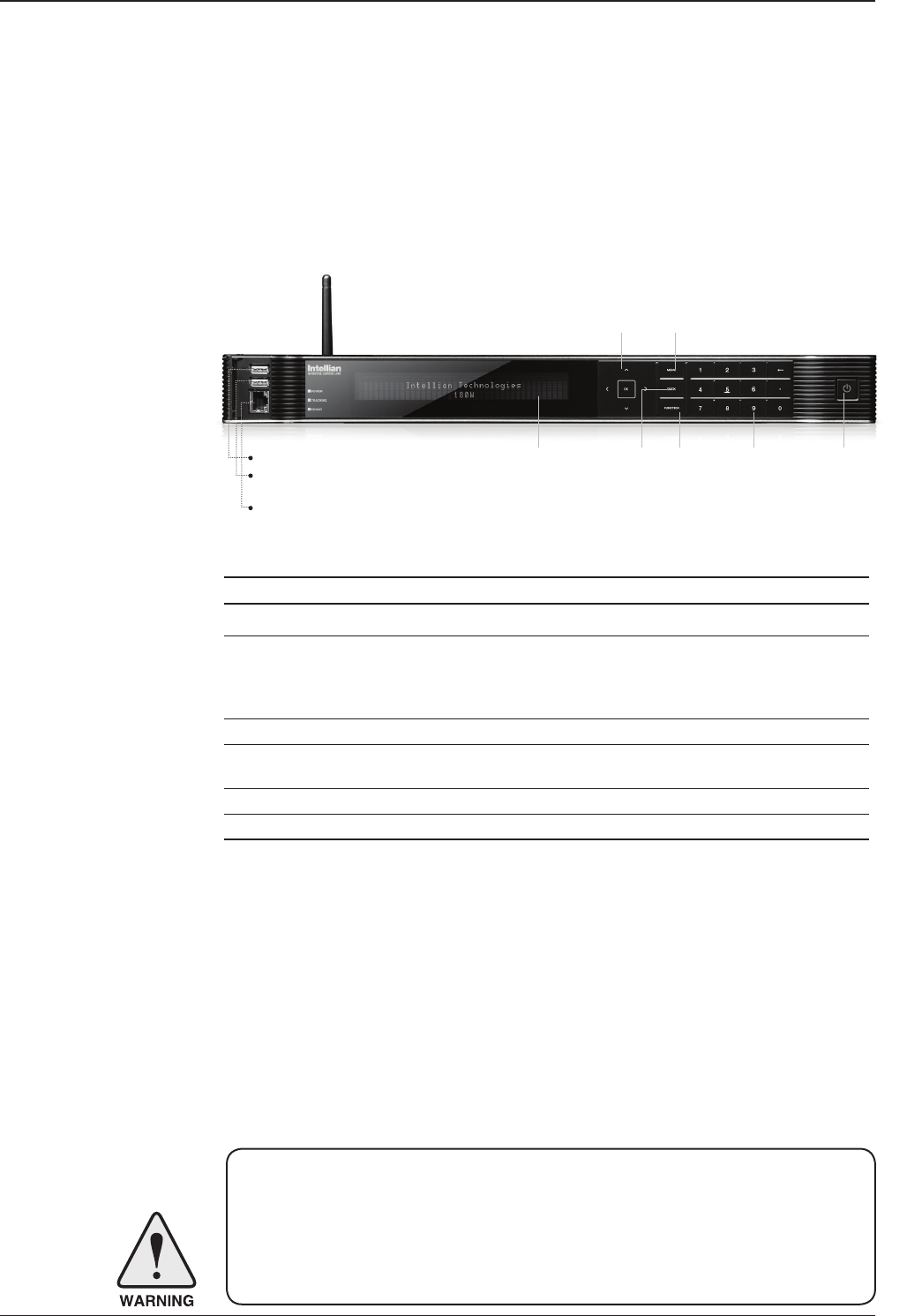
ACU Soft Keys
Soft key Function
MENU Enter SETUP mode
BACK
In SETUP mode: returns to the previous menu / option or save
the adjusted settings.
In normal mode: returns to the rst page of the antenna's current
status.
FUNCTION Save the adjusted settings.
ARROW KEYS Select from the alternative options to increse or decrese the
selected character to the desired value.
OK Enter the next step / menu
NUMBER KEYS Input the numbers
Soft Key Functions
Status VFD BACK FUNCTION Number Keys Power
MENUArrow Keys
PC : PC Cable (USB)
DN : Firmware upgrade or
Log data download (USB)
Management Ethernet port

47
OPERATING THE ACU
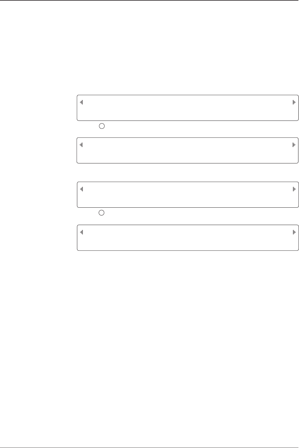
INTELLIAN TECHNOLOGIES INC.
INTELLIAN t80W
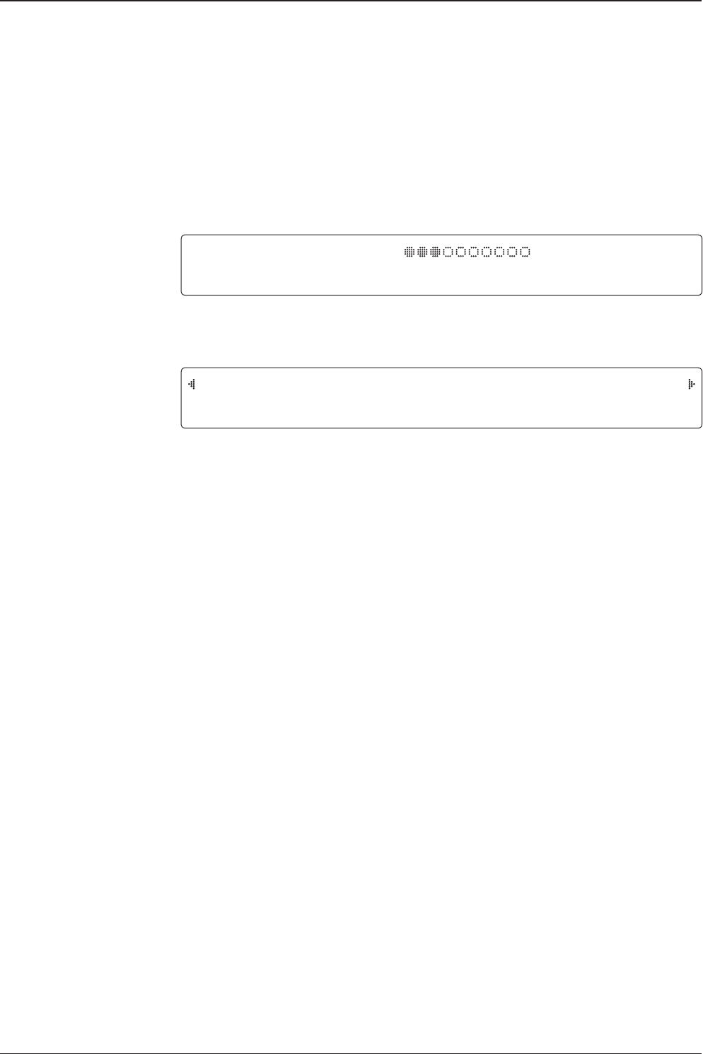
1. The data communication is being established between the antenna and the ACU.
INITIALIZE - ANTENNA INFO
INTELLIAN t80W
2. The ACU receives antenna information.
INITIALIZE - EL POSITION
INTELLIAN t80W
3. The elevation angle and cross level angle are initialized.
INITIALIZE - AZIMUTH POSITION
INTELLIAN t80W
4. The azimuth angle is initialized.
INITIALIZE - FIND NOISE LEVEL
INTELLIAN t80W
5. The antenna measures the noise levels of the default satellites.
INITIALIZE - SAT POSITION
INTELLIAN t80W
6. The antenna returns to the target satellite position.
7. The antenna is searching for the target satellite.
8. The antenna has locked onto the target satellite and is now tracking.
Startup
With the system installed and power applied, the ACU screen will show the following
sequence.
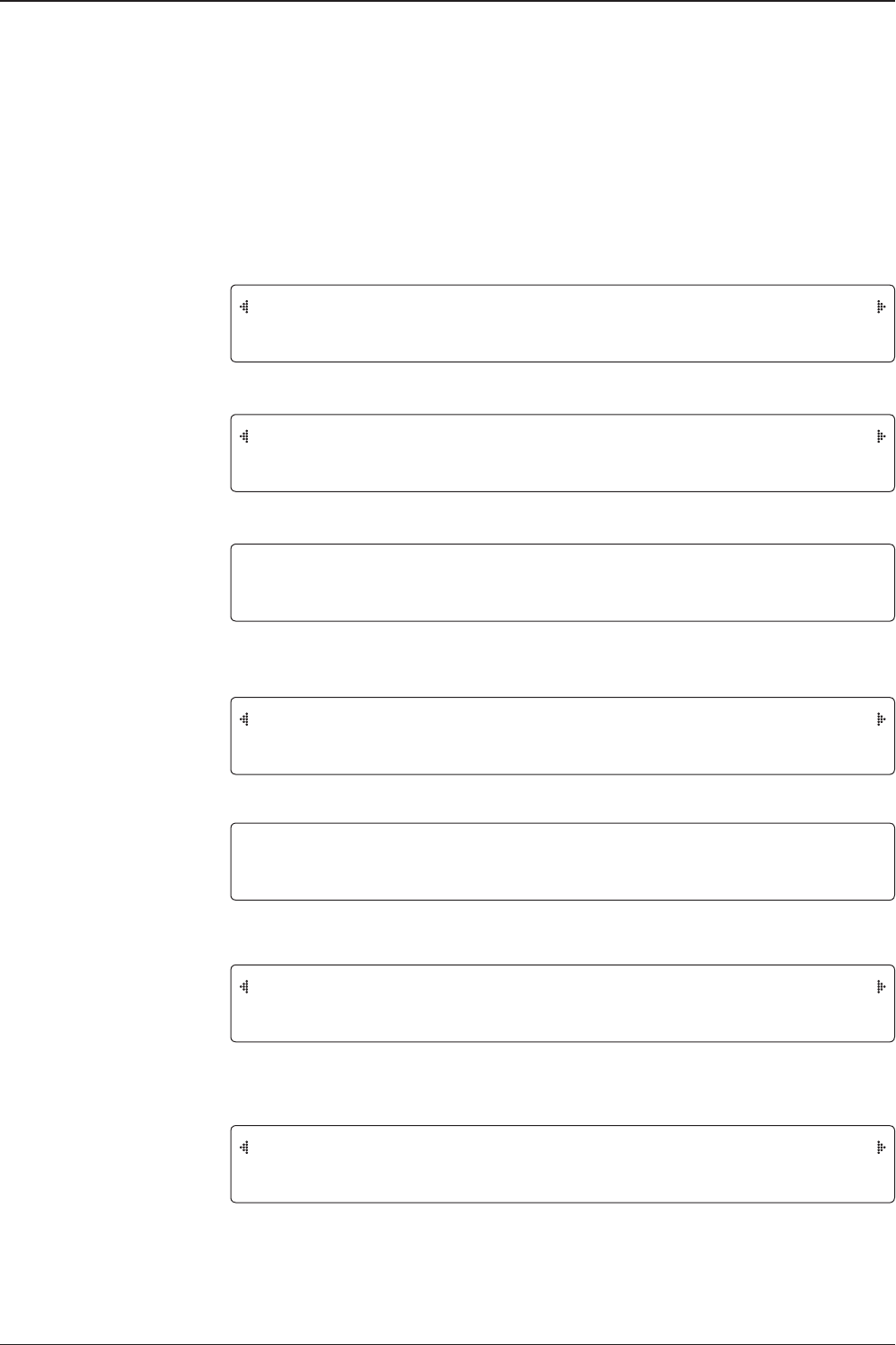
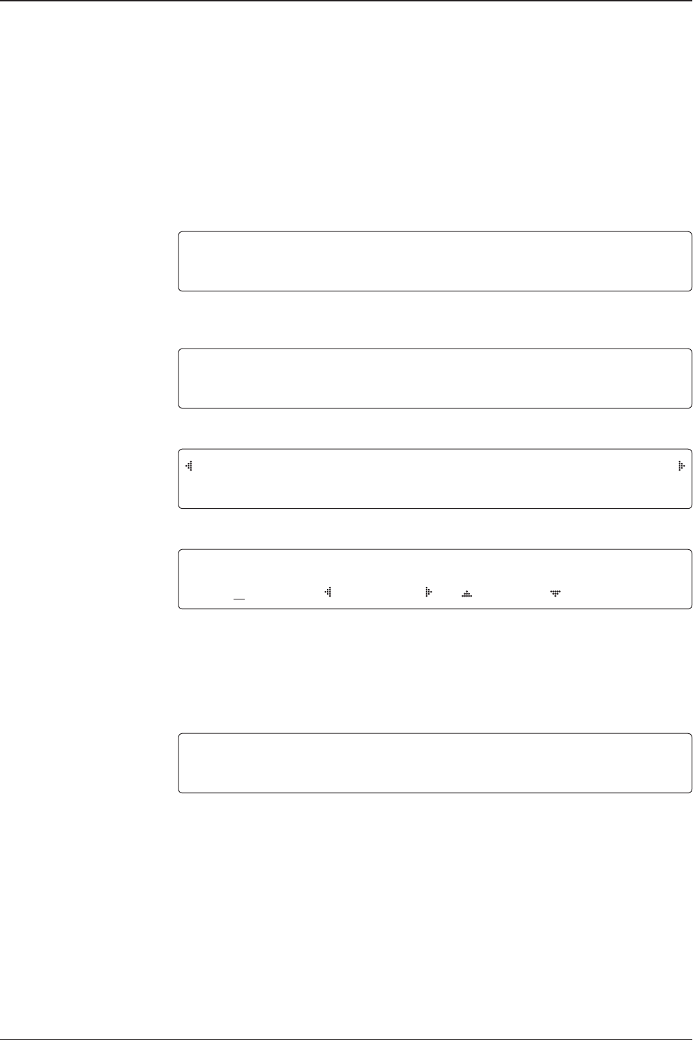
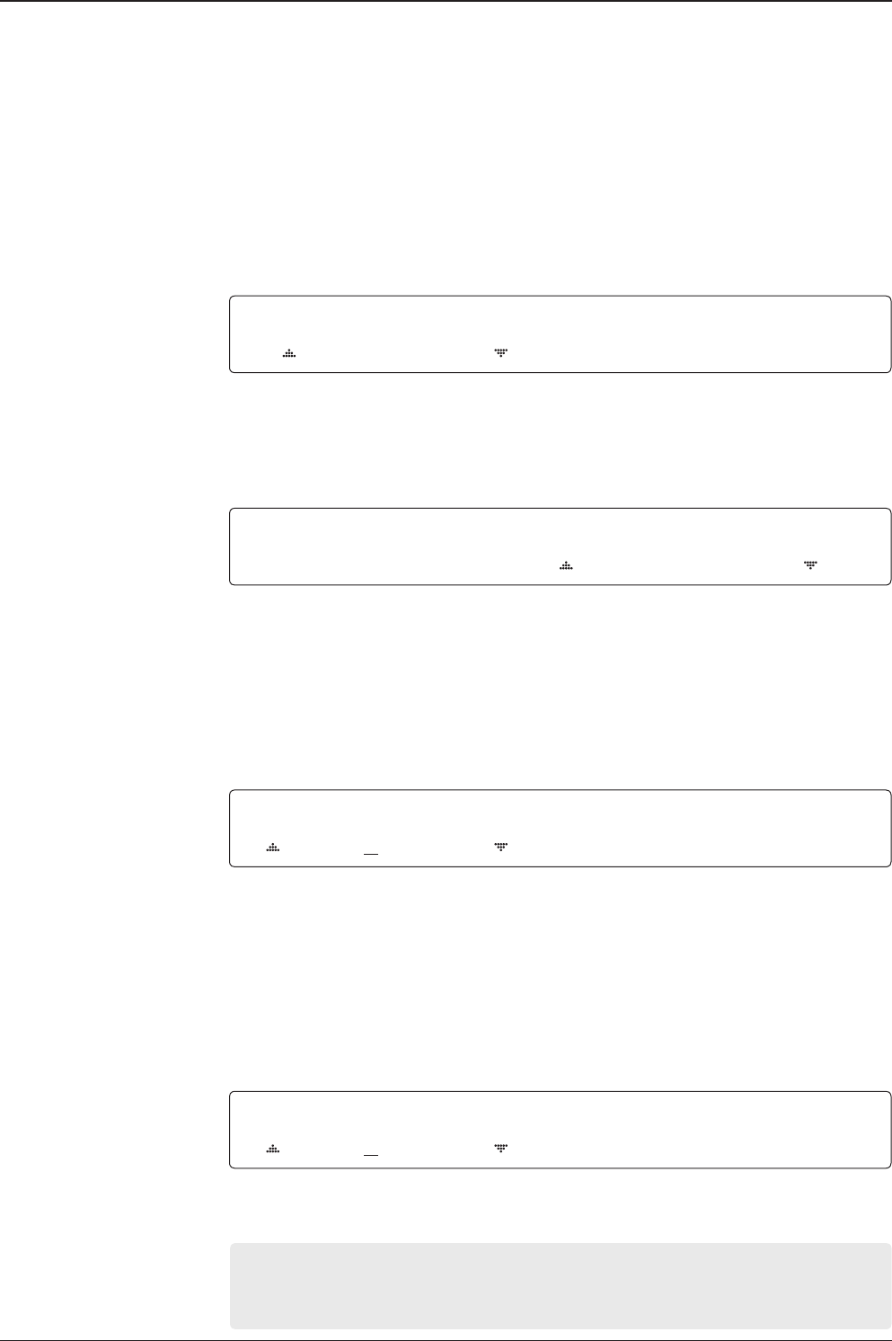
Normal Mode
SEARCH 19.2E ASTRA_1 AGC:301•VL
AZ:160.9(340.9) EL:29.0 SK:-21.1 Fn
TRACKING ASTRA_1 AGC:301•VL
AZ:160.9(340.9) EL:29.0 SK:-21.1 Fn
t80W – Marine Satellite TV Antenna System
48
TRACKING [4] ASTRA_1
[2] HOT_SPOT Fn
1. Press key for tracking satellite [2].
2. The antenna is tracking satellite [2].
3. Press key for tracking satellite [3] (when in Tri-sat mode).
4. The antenna is tracking satellite [3].
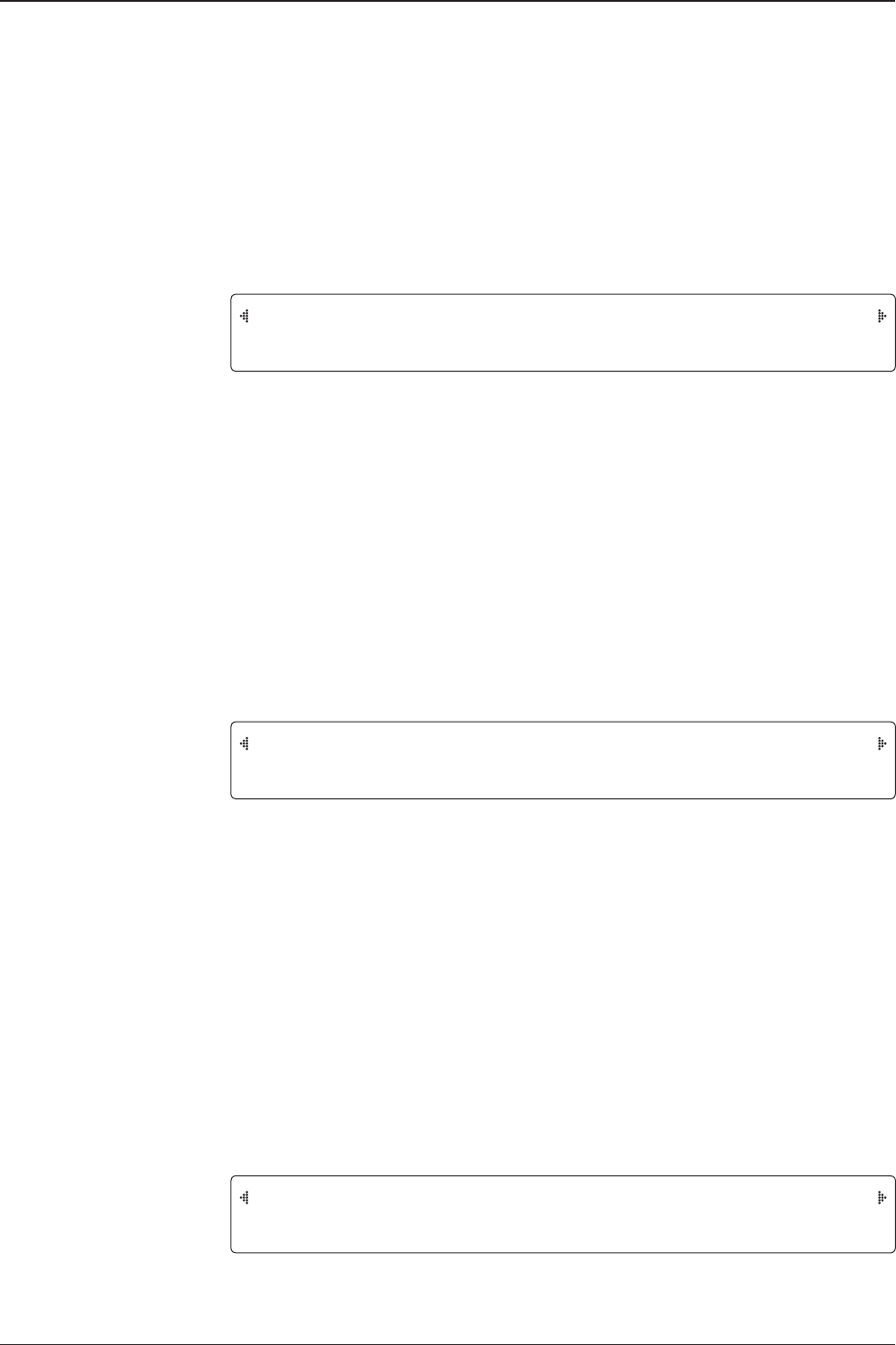
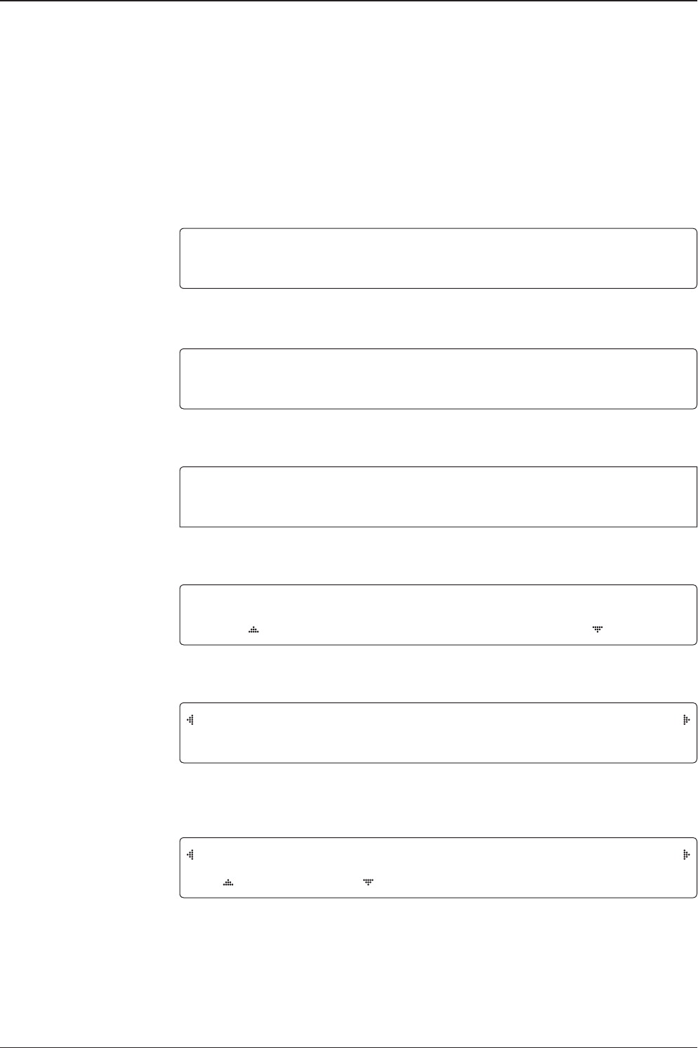
Change of Target Satellite
Your antenna is programmed with three selected target satellites as default.
To change the target satellite, press the LEFT soft key. The target satellite is
changed and is automatically tracked by the antenna.
TRACKING [4] HOT_S POT
[1] ASTRA_1 Fn
TRACKING [4] ASTRA_1
[2] HOT_SPOT [3] ASTRA_3 Fn
2
3
TRACKING [4] ASTRA_3
[1] ASTRA_1 [2] HOT_SPOT Fn
49
OPERATING THE ACU
1. The antenna is searching for satellite [ 1 ].
2. The antenna is tracking satellite [ 1 ].
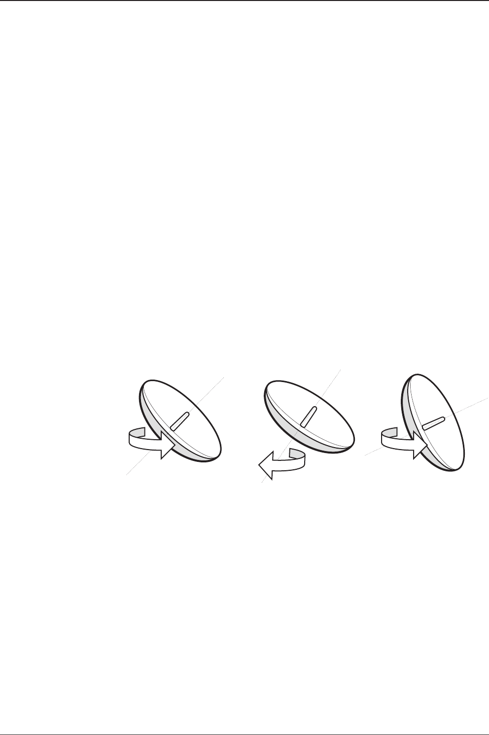
3. The antenna is winding /unwinding the cables in the antenna. The necessity of “unwrap”
is based on how far the ship has turned in one direction or the other.
4. The antenna is again tracking satellite [ 1 ].
5. Press the FUNCTION key to save current satellite information or abort and return to the
main display.
6. While the antenna is tracking satellite [ 1 ], press the RIGHT arrow key to display current
antenna information.
7. True azimuth [ 160.9] position of the antenna is the sum of ships heading 180.0
[ HDG ] and antenna relative [ 340.9 ]. Current IF signal level (AGC) is displayed .
• will be only displayed when signal is strong enough to lock. VL indicates vertical
low band. VH: vertical High, HL: horizontal low, HH: horizontal high. Press the UP and
DOWN arrow keys to increase and decrease the LNB skew angle .
If the Up and Down arrow keys are unseen, press the OK key three times.
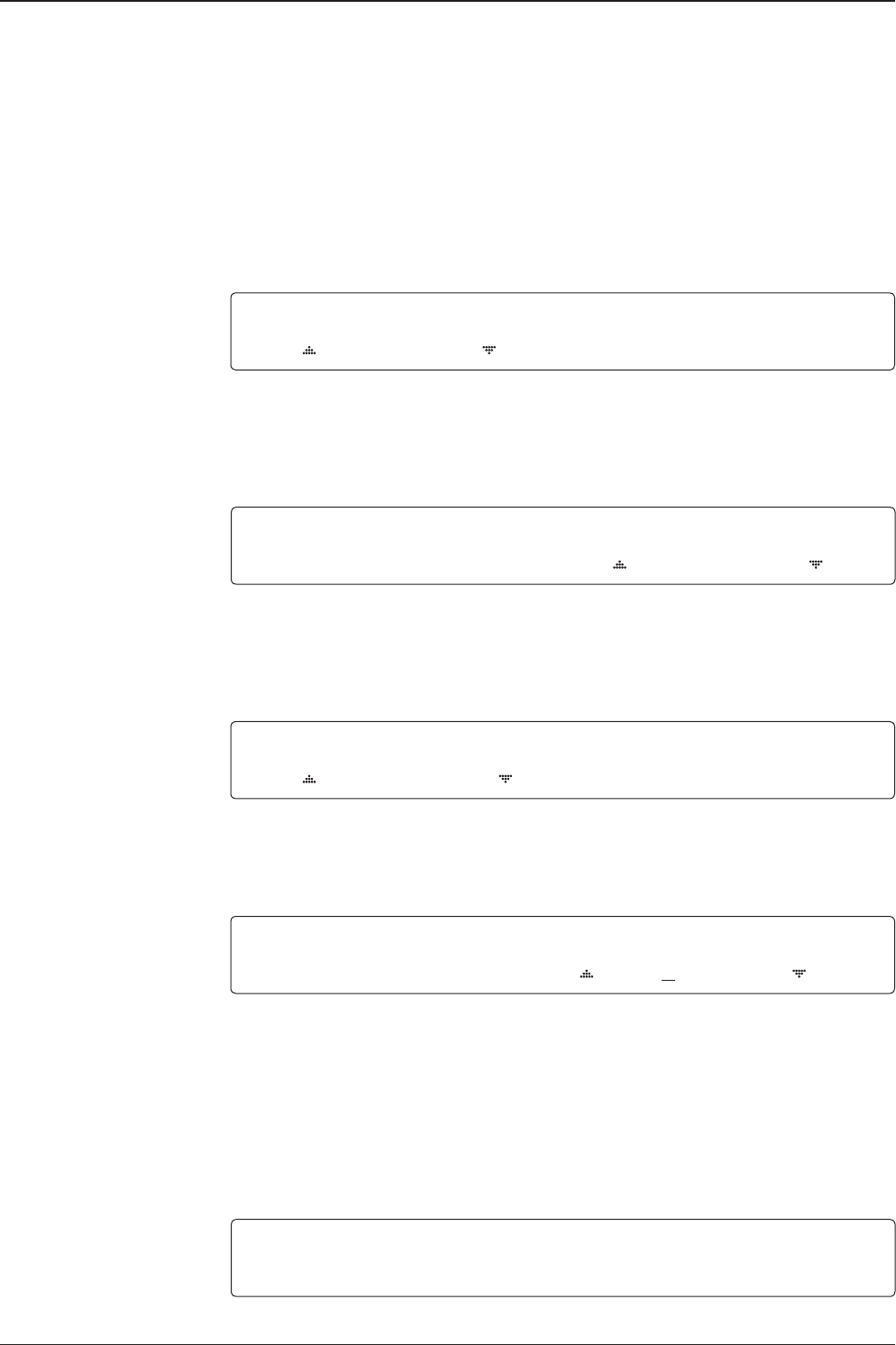
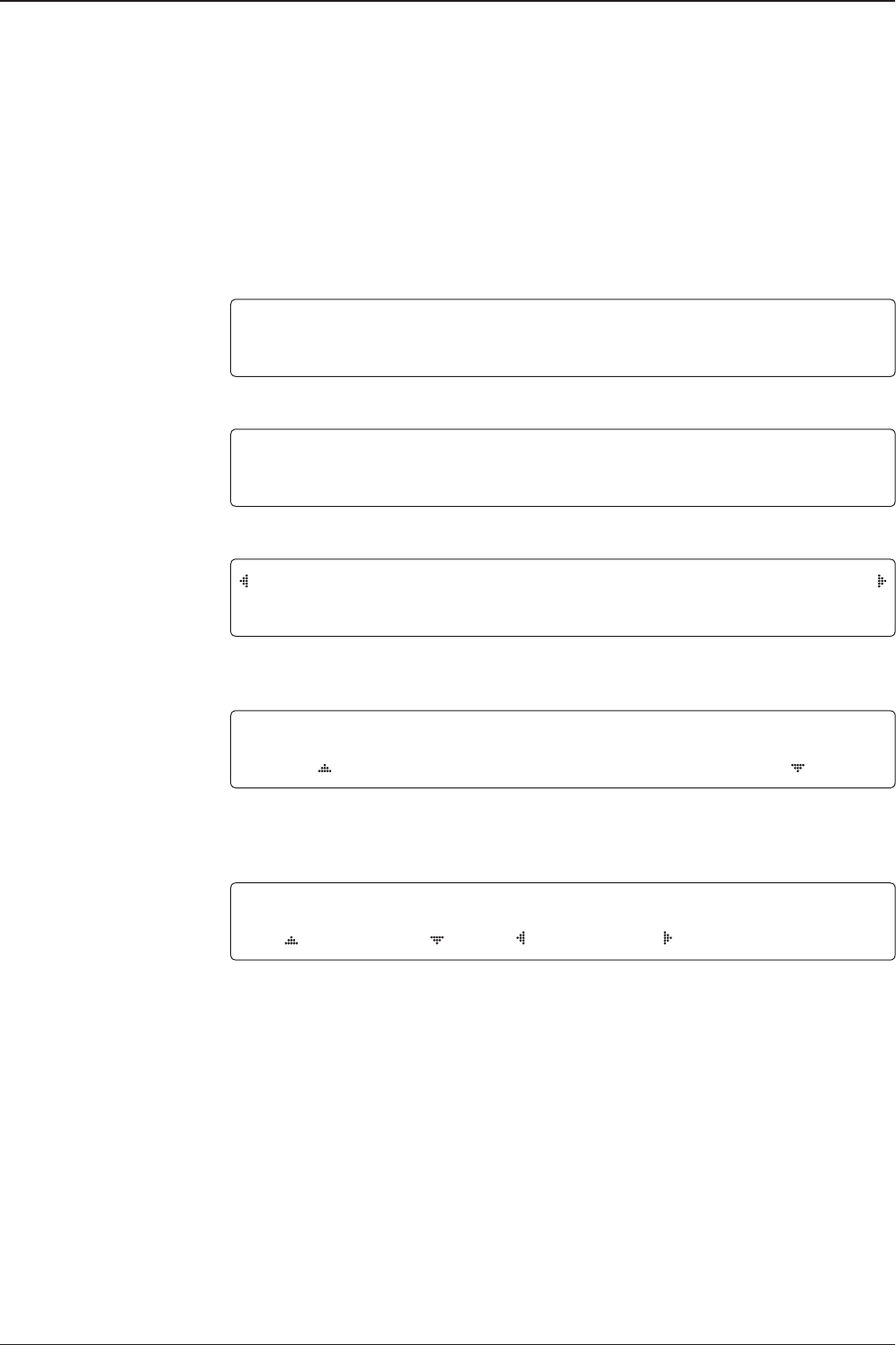
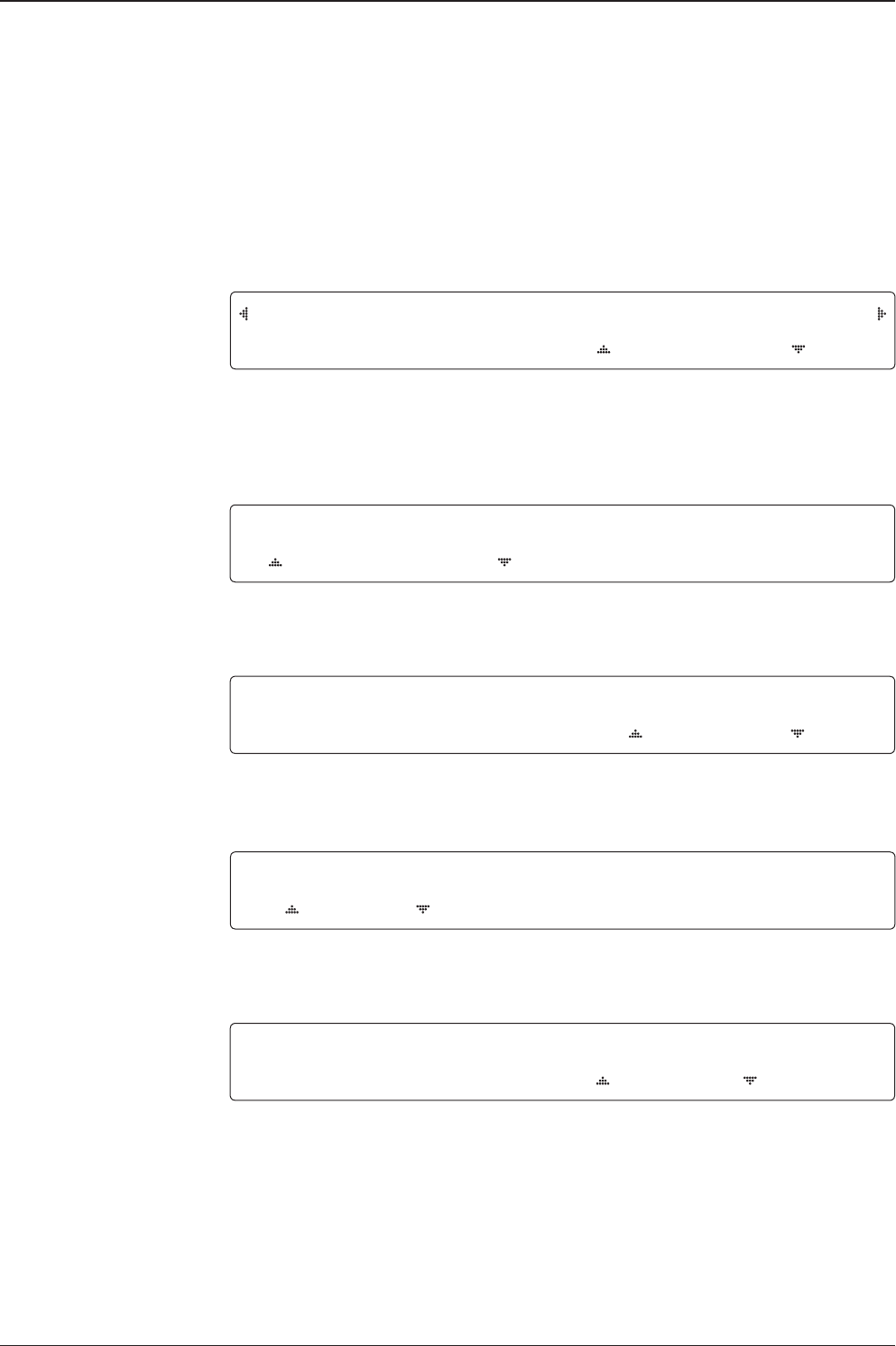
Monitoring Current Status
While POWER ON the Intellian t80W ACU displays the status of the antenna.
Various ACU displays may be shown according to the current status of the antenna.
SEARCH [4] ASTRA_1
[2] HOT_SPOT [3] ASTRA_3
TRACKING [4] ASTRA_1
[2] HOT_SPOT [3] ASTRA_3 Fn
TRACKING [4] ASTRA_1
[2] HOT_SPOT [3] ASTRA_3 Fn
TRACKING [4] ASTRA_1
[2] HOT_SPOT [3] ASTRA_3 Fn
TRACKING 19.2E ASTRA_1 AGC:301•VL
AZ:160.9( 340.9) EL:29.0 SK: -21.1 Fn
SAVE CURRENT SAT INFO?
4YES NO
ANTENNA IS UNWRAPPING
t80W – Marine Satellite TV Antenna System
50
8. Press the RIGHT arrow key to display current satellite, GPS and ship’s heading
[ HDG ] information.
Satellite Information :
Frequency : 11509 MHz
Symbol rate : 22000 kSps
Verication method : DVB_ Decode
LNB local frequency : 9750 MHz
GPS Information :
Longitude : West /East
Latitude : North/South
9. Press the RIGHT arrow key to display ACU and antenna ,LNB and IRD voltage informa-
tion.
Antenna and ACU Voltage :
Due to the voltage losses across the multi-conductor cables, ensure that the minimum
ACU operation voltage is within 27 ±1 V and minimum antenna operation voltage is above
16V.
LNB and IRD Voltage :
13 V + 0KHz (Vertical Low)
18V + 0KHz (Horizontal Low)
13V + DiSEqC 22 KHz tone (Vertical High)
18V + DiSEqC 22 KHz tone (Horizontal High)
10. Press the RIGHT arrow key to display Antenna, ACU and Library version.
Keep pressing the RIGHT arrow key to return to the main display.
DVB_D F:11509 S:22000 X0001 AGC:301
4.53E 52.22N HDG:000.0 L:9750 Fn
[PWR] ANT: 23.9V LNB:13V + 0KHz
ACU: 27.0V IRD:13V + 0KHz
W3-1117Q ANT.Serial 4.00/4.00
BP-TA01 ACU Serial 4.00(2.00)

51
OPERATING THE ACU
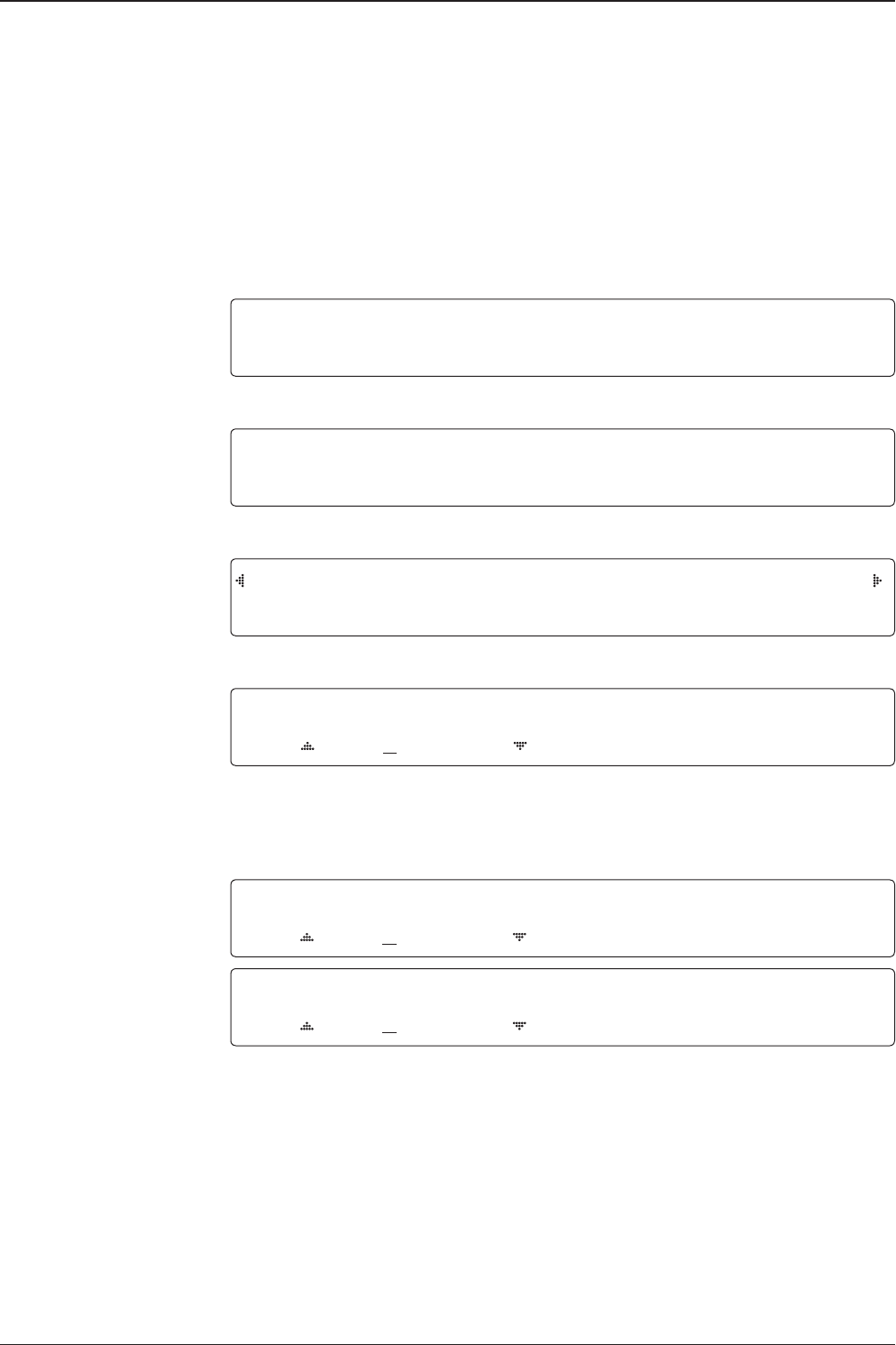
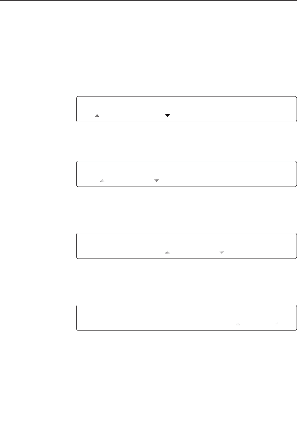
Setup Mode
To enter Setup Mode simply follow the instructions below:
1. While the antenna is tracking , press the MENU key for setup mode.
2. Press the LEFT key to move cursor to YES and press the OK key to enter setup mode
or press the RIGHT key to move cursor to NO and press the OK key to abort and return to
the main display.
TRACKING 19.2E ASTR_1 AGC:301•VL
AZ:160.9( 340.9) EL:29.0 SK: -21.1 Fn
SETUP MODE ?
4YES NO

t80W – Marine Satellite TV Antenna System
52
Installation Settings
SETUP MODE ?
4YES NO
1. Press the LEFT arrow key to move cursor to YES and press the OK key to enter setup
mode.
+ANTENNA +SATELLITE
+SYSTEM 4+INSTALLATION
2. Press the arrow keys to move cursor to INSTALLATION and press the OK key to enter
INSTALLATION menu.
4 SELECT CONTINENT SELECT REGION
EUROPE NETHERLANDS
3. Press the arrow keys to select parameter you wish to edit and press the OK key
to edit the selected parameter. Or press the BACK key to save or abort and return
to the main display.
SELECT CONTINENT SELECT REGION
EUROPE NETHERLANDS
4. Set the CONTINENT.
Press the UP and DOWN arrow keys to select the continent that you are in.
Press the OK key to set the CONTINENT.
SELECT CONTINENT SELECT REGION
EUROPE NETHERLANDS
5. Set the REGION.
Press the UP and DOWN arrow keys to select the region that you are in.
Press the OK key to set the REGION.
Installation
53
OPERATING THE ACU
6. Set the current LATITUDE .
Press the LEFT and RIGHT arrow keys until the desired character is underscored
(selected). Press the UP and DOWN arrow keys to increase or decrease the value.
Or press the NUMBER keys to set the desired value directly.
Press the OK key to set the LATITUDE.
7. Set the current LONGITUDE.
Press the LEFT and RIGHT arrow keys until the desired character is underscored (selected).
Press the UP and DOWN arrow keys to increase or decrease the value.
Or press the NUMBER keys to set the desired value directly.
Press the OK key to set the LONGITUDE.
8. Set the GYRO TYPE.
Determine the type of gyro compass that is used on the ship. Ensure that the Gyro
Type is set correctly. Press the UP and DOWN arrow keys to select the gyro type
and press the OK key to set the GYRO TYPE.
9. Set the BOW OFFSET
The radome should be positioned with the BOW marker aligned as close as possible to the
centerline of the ship. Small variations from actual alignment can be compensated with the
BOW OFFSET, so precise alignment is not required.
Press the LEFT and RIGHT arrow keys until the desired character is underscored
(selected). Press the UP and DOWN arrow keys to increase or decrease the value.
Or press the NUMBER keys to set the desired value directly.
Press the OK key to set the BOW OFFSET.
10. Press the BACK key to load the current setting or abort and return to the main display.
LATITUDE LONGITUDE
52.33N 4.53E
GYRO TYPE BOW OFFSET
NMEA 000
GYRO TYPE BOW OFFSET
NMEA 000
LOAD ?
4 YES NO
LATITUDE LONGITUDE
52.22N 4.53E
t80W – Marine Satellite TV Antenna System
54
10. Setting is being loaded to the system.
The ACU will restart the system automatically after uploading the setting.
DO NOT turn off ACU power while uploading is being processed.
11. Region information has been updated.
LOADING ...
DO NOT TURN OFF !
SEARCH [4] ASTRA_1
[2] HOT_SPOT [3]ASTRA_3
55
OPERATING THE ACU
Antenna Settings
Setting Antenna Manual Search
SETUP MODE ?
4 YES NO
1. Press the LEFT arrow key to move cursor to YES and press the OK key to enter SETUP
mode.
4+ANTENNA +SATELLITE
+SYSTEM +INSTALLATION
2. Press the OK key to enter ANTENNA menu.
4+MANUAL SEARCH +SET POL ANGLE
+SEARCH PARAM +SET PARAMETERS
3. Press the OK key to enter MANUAL SEARCH menu.
STEP SIZE AZIMUTH ELEVATION AGC
# 0.2 # 288.7 41.0 288 Fn
4. Current IF signal level (AGC) is displayed to assist you in manually peaking EL
for best signal level. Press the NUMBER key to change the step size(Range :
0.1~9.9). Press the LEFT and RIGHT arrow keys to move azimuth by step size
(Range : 0~360). Press the UP and DOWN arrow keys to move elevation by step
size(Range : 0~90). Press the FUNCTION key to save the bow offset when the antenna
locks onto the peak level of the AGC signal.
SAVE CURRENT SAT INFO?
4 YES NO
5. If the current settings are able to lock onto the satellite, press the LEFT key to
move cursor to YES and press the OK key to save the bow offset. It will shorten the
satellite acquisition time next time. Or you can press the RIGHT key to move
cursor to NO and press the OK key to abort and return to the previous view.
t80W – Marine Satellite TV Antenna System
56
Setting POL. Angle
SETUP MODE ?
4 YES NO
1. Press the LEFT key to move cursor to YES and press the OK key to enter setup mode.
4+ANTENNA +SATELLITE
+SYSTEM +INSTALLATION
2. Press the OK key to enter ANTENNA menu.
+MANUAL SEARCH 4 +SET POL ANGLE
+GO POSITION +SEARCH PARAMETERS
3. Press the RIGHT arrow key to move cursor to SET POL ANGLE and press OK key to enter
SET POL ANGLE menu.
SELECT LNB POL. ANGLE MENU
CALIBRATION
4. Press the UP and DOWN arrow keys to select the menu and press the OK key to run the
selected operation ‘ CALIBRATION ‘ or ‘ MANUAL ADJUST‘. When you replace the control
board, select CALIBRATION to calibrate LNB skew angle.
5. Press the UP and DOWN arrow keys to increase or decrease the LNB skew angle manually.
Press BACK key to return to the main display.
Press the LEFT and RIGHT arrow keys to select the polarization between Linear and Circular.
Press BACK key to return to the main displa
LNB POL ANGLE POLARITY SIGNAL :180
20.0 LINEAR
57
OPERATING THE ACU
Setting Antenna Search Parameter
SETUP MODE ?
4 YES NO
1.Press LEFT arrow key to move cursor to YES and press OK key to enter SETUP mode.
4+ANTENNA +SATELLITE
+SYSTEM +INSTALLATION
2. Press OK key to enter ANTENNA menu.
+MANUAL SEARCH +SET POL ANGLE
+SEARCH PARAM 4+SET PARAMETER
3. Press DOWN arrow keys to move cursor to SEARH PARAM and press OK key to it.
SEARCH WAIT TIME INCREMENT STEP
030 0.50
4. Set SEARCH WAIT TIME and INCREMENT STEP
Set the time-out for automatic initiation of a search after the signal level drops below the
predened threshold value (Range : 1 - 120 sec) and set increment step size (Range : 0.01
– 5.00 sec).
5.Set SEARCH 1 and 3 AZ(Azimuth) range and EL (Elevation) range.
SEARCH 2 is reserved for future use.
SEARCH1 AZ SEARCH1 EL
400 06
SEARCH3 AZ SEARCH3 EL
003 04
t80W – Marine Satellite TV Antenna System
58
A search pattern 1 or 3 will be initiated according to which GYRO TYPE is selected and
the existence of the gyro input.
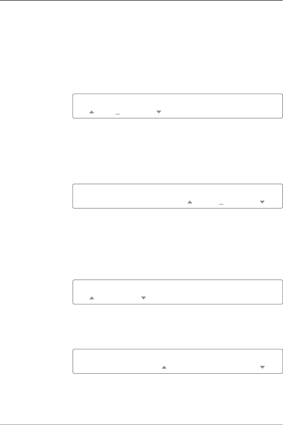
Search 1: a search pattern 1 will automatically be initiated when the ship’s heading
input does not exist / is failed .The antenna will go to the relative azimuth
position 0°at the calculated elevation and search in the azimuth CW and CCW direction
in a turn rotation and search up + 0.5° & down -0.5° with a total 6 (±3°) in elevation. The
search cycle will repeat until the antenna receives the lock signal from the receiver or the
DVB transponder of the target satellite is decoded by the antenna. If the desired signal is
found and above the predened detect level, the ACU will enter to Search 3. However,
the antenna will not initiate Search 3 pattern but go into TRACKING mode immediately if
the desired signal is above the predened tracking threshold level. If the detected signal
is below the predened tracking threshold level, the search 1 will repeat and start 3°
away from the current position.
Search 1 Antenna Motion
Target EL Angle
Turn 1
Target EL Angle + 0.5°
(or dened step size)
Turn 2
Target EL Angle -0.5°
(or dened step size)
Turn 3

59
OPERATING THE ACU
Search 3: a search pattern 3 will automatically be initiated when AGC falls below
the current tracking level threshold value. If the desired signal is found and above the
predened tracking level, the ACU will terminate Search 3 and go into TRACKING mode.
A search pattern will automatically be initiated when AGC falls below the current
threshold setting (indicates that satellite signal has been lost). Search is conducted
in a two-axis pattern consisting of alternate movements in azimuth (AZ) and elevation
(EL) as forming expanding square indicated as below diagram.
Elevation
(EL) Range
step size
Azimuth (AZ) Range
0.5˚
t80W – Marine Satellite TV Antenna System
60
Setting Antenna Parameters
SETUP MODE ?
4 YES NO
1. Press the LEFT key to move cursor to YES and press the OK key to enter setup mode.
4+ANTENNA +SATELLITE
+SYSTEM +INSTALLATION
2. Press the OK key to enter ANTENNA menu.
+MANUAL SEARCH +SET POL ANGLE
+SEARCH PARAM 4+SET PARAMETERS
3. Press the RIGHT arrow key to move cursor to SET PRAMETERS menu and press the OK
key to enter SET PARAMETERS menu.
ENTER PASSWORD
- - - -
4. Access to the password protected system. Setup parameters is only required after
installation or repairs of your antenna system. These parameters should only be changed
by an authorized service technician. Improper setting of these parameters will cause your
system to perform improperly.
Press 4-digit password to enter SET PRAMETERS menu. (1590).
DETECT LEVEL TRACKING LEVEL
060 030
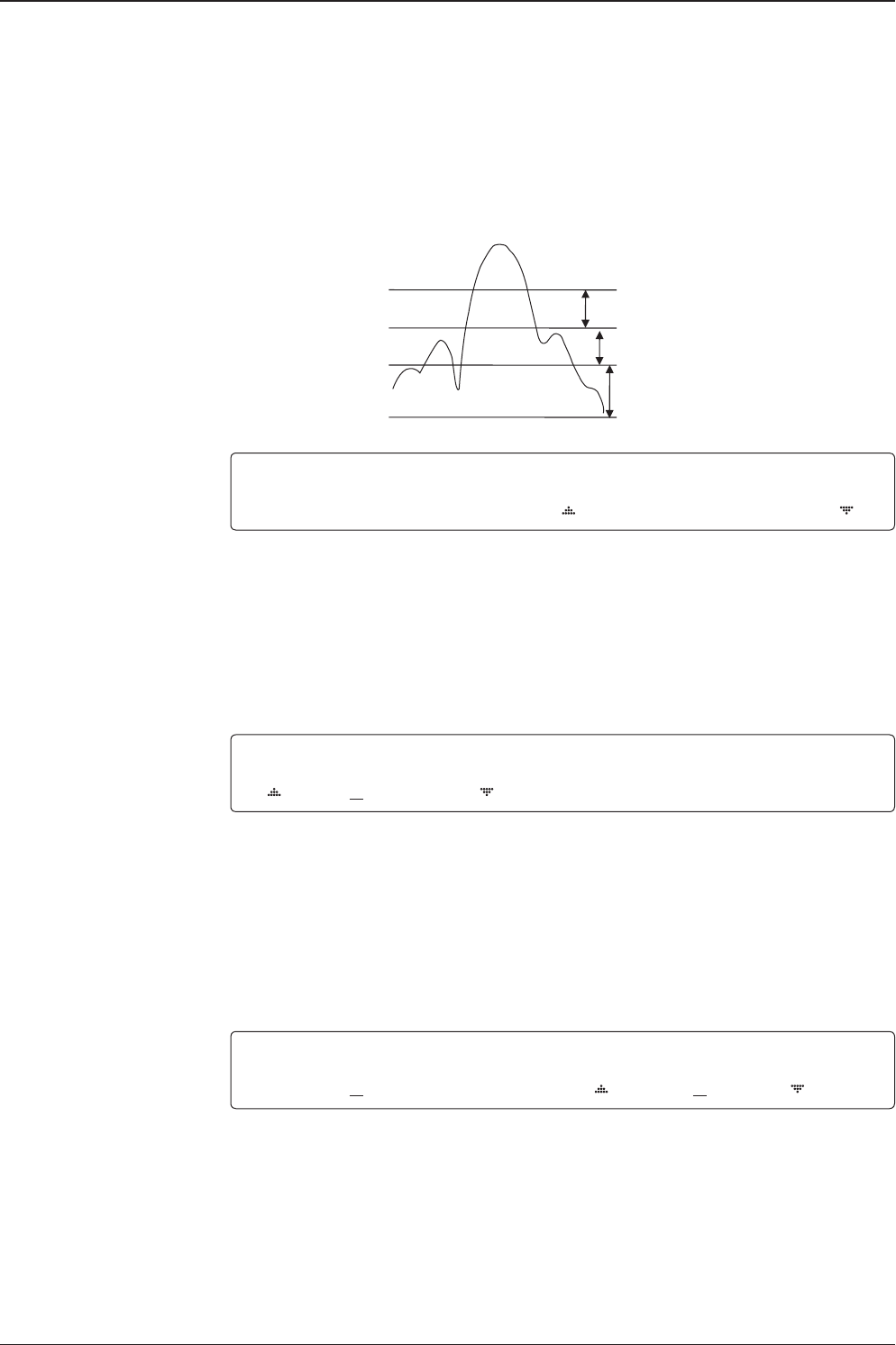
5. Set the DETECT LEVEL. (Range : 1-200)
The detect level is to set the satellite signal detection level.
Press the LEFT and RIGHT arrow keys until the desired character is underscored
(selected). Press the UP and DOWN arrow keys to increase and decrease the
selected character. Or press the NUMBER keys to set the desired value directly.
Press the OK key to set the new DETECT LEVEL.
61
OPERATING THE ACU
BOW OFFSET EL.ADJUST
000 +0.0
BOW OFFSET EL.ADJUST
000 +0.0
DETECT LEVEL TRACKING LEVEL
060 030
6. Set the TRACKING LEVEL. (Range : 1-200)
The tracking level is to set the satellite signal tracking level.
Press the LEFT and RIGHT arrow keys until the desired character is underscored
(selected). Press the UP and DOWN arrow keys to increase and decrease the
selected character. Or press the NUMBER keys to set the desired value directly.
Press the OK key to set the new TRACKING LEVEL.
7. Set the BOW OFFSET. (Range :0 – 360°)
The bow offset is to offset the angle difference between the antenna’s bow and the ship’s
bow.
Press the LEFT and RIGHT arrow keys until the desired character is underscored
(selected). Press the UP and DOWN arrow keys to increase and decrease the
selected character. Or press the NUMBER keys to set the desired value directly.
Press the OK key to set the new BOW OFFSET.
8. Set the EL ADJUST. (Range : ± 5°)
The elevation adjust is to offset the angle difference between the mechanical elevation
angle and actual elevation angle.
Press the LEFT and RIGHT arrow keys until the desired character is underscored
(selected). Press the UP and DOWN arrow keys to increase and decrease the
selected character. Or press the NUMBER keys to set the desired value directly.
Press the OK key to set the new EL ADJUST.
Noise Level
Detect Level
Tracking Level
Peak Level
t80W – Marine Satellite TV Antenna System
62
9. Set the VOLT THRES.
The voltage threshold is to distinguish the voltage between 13 V and 18V.
Press the LEFT and RIGHT arrow keys until the desired character is underscored
(selected). Press the UP and DOWN arrow keys to increase and decrease the
selected character. Or press the NUMBER keys to set the desired value directly.
Press the OK key to set the new VOLT THRES.
10. Set the SCAN OFFSET. (Range : 0 - 90)
The scan offset is to offset the angle difference between the black marker on the
sub-reector and the optical sensor.
Press the LEFT and RIGHT arrow keys until the desired character is underscored
(selected). Press the UP and DOWN arrow keys to increase and decrease the
selected character. Or press the NUMBER keys to set the desired value directly.
Press the OK key to set the new SCAN OFFSET.
11. Set the USE WRS.
USE WRS is to determine whether the system uses WRS LEVEL or not.
USE WRS and WRS LEVEL are pair functions.
Press the UP and DOWN arrow keys to select “YES” to USE WRS or “NO” to NOT USE
WRS and press the OK key to set the USE WRS.
12. Set the WRS DETECT LEVEL. (Range : 10 – 5,000)
The WRS level is to set the WRS detection level.
Press the LEFT and RIGHT arrow keys until the desired character is underscored
(selected). Press the UP and DOWN arrow keys to increase and decrease the selected
character. Or press the NUMBER keys to set the desired value directly.
Press the OK key to set the new WRS DETECT LEVEL.
VOLT THRES. SCAN OFFSET
0650 55
VOLT THRES. SCAN OFFSET
0650 55
USE WRS WRS DETECT LEVEL
YES 0400
USE WRS WRS DETECT LEVEL
YES 0400
63
OPERATING THE ACU
13. Set the USE OFFSET.
USE OFFSET is to determine whether the system uses OFFSET DIFF or not.
USE OFFSET and OFFSET DIFF are pair functions.
Press the UP and DOWN arrow keys to select “YES” to USE OFFSET or “NO” to
NOT USE OFFSET and press the OK key to set the USE OFFSET.
14. Set the OFFSET DIFF. (Range : ±100 )
The offset difference is to offset the signal difference between RHCP and LHCP.
Press the LEFT and RIGHT arrow keys until the desired character is underscored (selected).
Press the UP and DOWN arrow keys to increase and decrease the selected character. Or
press the NUMBER keys to set the desired value directly.
Press the OK key to set the new OFFSET DIFF.
15. Set the VERIFY TIME. (Range : 10 ~ 5000 )
The VERIFY TIME is to set the time of decoding to verify whether the signal detected is the
signal of the target satellite.
Press the LEFT and RIGHT arrow keys until the desired character is underscored (selected).
Press the UP and DOWN arrow keys to increase and decrease the selected character.
Or press the NUMBER keys to set the desired value directly.
Press the OK key to set the new VERIFY TIME.
16. Set OPERATION
Press UP and DOWN arrow keys to select OPERATION items.
USE OFFSET OFFSET DIFF.
YES -040
VERIFY TIME OPERATION
1500 SAVE
VERIFY TIME OPERATION
1500 SAVE
USE OFFSET OFFSET DIFF.
YES -040
OPERATION*
SAVE : Save and execute the current settings.
REBOOT : The antenna will restart automatically if REBOOT ANTENNA is ON.

t80W – Marine Satellite TV Antenna System
64
Executing Antenna Diagnosis
SETUP MODE ?
4 YES NO
1. Press the LEFT key to move cursor to YES and press the OK key to enter setup mode.
4+ANTENNA +SATELLITE
+SYSTEM +INSTALLATION
2. Press the OK key to enter ANTENNA menu.
4 +DIAGNOSTIC
3. Press the arrow keys to move cursor to DIAGNOSTIC and press the OK key to enter
DIAGNOSTIC menu.
DIAGNOSTIC FULL TEST
FULL TEST READY
4. Press the UP and DOWN arrow keys to select a full diagnosis or single diagnosis and press
the OK key to execute the selected diagnosis.
DIAGNOSTIC FULL TEST
FULL TEST - 5
5. A full diagnosis is completed.
DIAGNOSTIC COMMUNICATION
CODE 101 RESULT : PASSED
6. The diagnosis result is shown.

65
OPERATING THE ACU
Diagnosis Code :
CODE 101 : The data communication between the antenna and the ACU is tested.
CODE 102 : The azimuth motor is tested.
CODE 103 : The elevation motor is tested.
CODE 104 : The cross-level motor is tested.
CODE 105 : The azimuth encoder is tested.
CODE 106 : The cross-level encoder is tested.
CODE 107 : The gyro sensor is tested.
CODE 108 : The tilt sensor is tested.
CODE 109 : The sensor box motor is tested.
CODE 110 : The LNB is tested .
CODE 111 : The LNB skew motor is tested.
CODE 112 : The sub-reector is tested.
CODE 113 : The antenna power is tested.
CODE 114 : The ACU power is tested.
CODE 115 : The receiver power is tested.
Test result: •2••-••••••••••
• Test means passed. – Test means skipped. ? Test means under process.
Refer No. 2 to the diagnosis code 102 as shown above for occurred error explanation.

t80W – Marine Satellite TV Antenna System
66
Satellite Settings
Setting the Satellite Pair
SETUP MODE ?
4 YES NO
1. Press the LEFT arrow key to move cursor to YES and press the OK key to enter setup
mode.
+ANTENNA 4+SATELLITE
+SYSTEM +INSTALLATION
2. Press the RIGHT arrow key to move cursor to SATELLITE and press the OK key to enter
SATELLITE menu.
4+SET SAT.PAI R +EDIT SATELLITE
+SET REGION +FIND TRANSPONDER
3. Press the OK key to enter SET SAT. PAIR menu.
SET TRIPLE SAT ?
4 YES NO
4. Move cursor to YES and press the OK key to enter Tri-Sat mode or move cursor to NO
and press the OK key to enter Dual-Sat mode.
PRESET SLOT DEST.SATELLITE
PRESET 1 ASTRA_1
5. Press the UP and DOWN arrow keys to select PRESET SLOT 1, 2 and 3 in Tri-Sat mode
or 1 and 2 in Dual-Sat mode.
6. Press the UP and DOWN arrow keys to select the DESTINED SATELLITE from the library
(pre-programmed satellites). Press the OK key to set the DESTINED SATELLITE.
7. Press the BACK key to save the current settings or abort and return to the main display.
RESET SLOT DEST.SATELLITE
PRESET 1 ASTRA_1
SAVE ?
4 YES NO
67
OPERATING THE ACU
Edit Satellite Information
SETUP MODE ?
4 YES NO
1. Press the LEFT arrow key to move cursor to YES and press the OK key to enter setup
mode.
+ANTENNA 4+SATELLITE
+SYSTEM +INSTALLATION
2. Press the RIGHT arrow key to move cursor to SATELLITE and press the OK key to enter
SATELLITE menu.
+SET SAT.PAI R 4+EDIT SATELLITE
+SET REGION +FIND TRANSPONDER
3. Press the RIGHT arrow key to move cursor to EDIT SATELLITE and press the OK key to
enter EDIT SATELLITE menu.
SELECT SATELLITE TO EDIT
ASTRA_A 19.20E
4. Press the UP and DOWN arrow key to select the satellite that you whish to edit and press
the OK key to edit the selected satellite.
LONGITUDE EDIT NAME
19.20E ASTRA_1
5. Press the RIGHT and LEFT arrow keys to select parameter that you whish to edit.
Press the OK key to edit parameter.
Press the BACK key to save or abort and return to the main display.
LONGITUDE EDIT NAME
19.20E ASTRA_1
6. Set the SATELLITE LONGITUDE .
Press the LEFT and RIGHT arrow keys until the desired character is underscored(selected).
Press the UP and DOWN arrow keys to increase or decrease the value.
Or press the NUMBER keys to set the desired value directly.
Press the OK key to set the SATELLITE LONGITUDE.
t80W – Marine Satellite TV Antenna System
68
7. Set the SATELLITE NAME.
Press the LEFT and RIGHT arrow keys until the desired character is underscored(selected).
Press the UP and DOWN arrow keys to increase or decrease the value.
Or press the NUMBER keys to set the desired value directly.
Press the OK key to set the SATELLITE NAME.
8. Set the satellite VERIFICATION TYPE.
Press the UP and DOWN arrow keys to select the Verication Method 1) while antenna is
tracking the satellite signal and press the OK key to set the VERIFY TYPE.
9. Set the LNB VOLTAGE.
Press the UP and DOWN arrow keys to select the LNB Voltage Supply Method 2) and press
the OK key to set the VOLTAGE (“AUTO” is recommended ).
10. Set the DISEQC .
Press the UP and DOWN arrow keys to select the DiSEqC Method 3) and press the OK key
to set the DISEQC ( “AUTO” is recommended ).
11. Set the POL TYPE manually.
Press the UP and DOWN arrow keys to manually select LINEAR or CIRCULAR and press the
OK key to set the POL TYPE.
VERIFY TYPE VOLTAGE
DVB DECODE AUTO
VERIFY TYPE VOLTAGE
DVB DECODE AUTO
DISEQC POL.TYPE
AUTO LINEAR
DISEQC POL.TYPE
AUTO LINEAR
LONGITUDE EDIT NAME
19.20E ASTRA_1
69
OPERATING THE ACU
LOCAL FREQ.
10600
12. Set LOCAL FREQ.
Press the UP and DOWN arrow keys to select the LNB local frequency from the
installed LNB. Or press the NUMBER keys to set the desired value directly.
Press the OK key to set the parameter.
VL FREQ SYMBOL NID
115094MHZ 22000kSps 0X0001
13-1. Set the satellite FREQUENCY for VL( Vertical Low) band.
Press the LEFT and RIGHT arrow keys until the desired character is underscored
(selected). Press the UP and DOWN arrow keys to increase or decrease the value.
Or press the NUMBER keys to set the desired value directly.
Press the OK key to set the FREQUENCY.
VL FREQ SYMBOL NID
115094MH Z 22000kSps 0X0001
13-2. Set the frequency SYMBOL rate (Maximum: 45,000).
Press the LEFT and RIGHT arrow keys until the desired character is underscored
(selected). Press the UP and DOWN arrow keys to increase or decrease the value.
Or press the NUMBER keys to set the desired value directly.
Press the OK key to set the SYMBOL.
VL FREQ SYMBOL NID
115094MHZ 22000kSps 0X0001
13-3. Set the frequency NID (Network ID). Range is 0x0000 – 0xFFFF.
Press the LEFT and RIGHT arrow keys until the desired character is underscored
(selected). Press the UP and DOWN arrow keys to increase or decrease the value.
Or press the NUMBER keys to set the desired value directly.
Press the OK key to set the NID.
Continue to press the OK key to set the satellite frequency, symbol rate and NID
for HL(Horizontal/LHCP Low), VH (Vertical/RHCP High) and HH (Horizontal/LHCP High) in
sequence.

t80W – Marine Satellite TV Antenna System
70
1) Verication Method
AGC – use signal level for satellite tracking.
DVB LOCK – use DVB Lock for satellite tracking.
DVB DECODE – use DVB Decode for satellite tracking.
DSS DECODE – use DSS Decode for satellite tracking.
2) Voltage Supply Method
AUTO- supply 13V or 18V to LNB.
ONLY 13V – always supply 13V to LNB.
ONLY 18V – always supply 18V to LNB.
3) DISEQC Method
AUTO – supply 0kHz or 22kHz to LNB.
ONLY 0KHZ – always supply 0kHz to LNB.
ONLY 22KHZ - always supply 22kHz to LNB.
71
OPERATING THE ACU
SETUP MODE ?
4 YES NO
1. Press the LEFT arrow key to move cursor to YES and press the OK key to enter SETUP
mode.
+ANTENNA 4+SATELLITE
+SYSTEM +INSTALLATION
2. Press the LEFT arrow key to move cursor to SATELLITE and press the OK key to
enter SATELLITE menu.
+SET SAT.PAIR +EDIT SATELLITE
4+SET REGION +FIND TRANSPONDER
3. Press the DOWN arrow key and the OK key to enter SET REGION menu.
4SELECT CONTINENT SELECT REGION
EUROPE NETHERLANDS
4. Press the arrow keys to select parameter you wish to edit and press the OK key
to edit parameter. Press the BACK key to save or abort and return to the main display.
SELECT CONTINENT SELECT REGION
EUROPE NETHERLANDS
5. Set the CONTINENT.
Press the UP and DOWN arrow keys to select the continent that you are in.
Press the OK key to set the CONTINENT.
SELECT CONTINENT SELECT REGION
EUROPE NETHERLANDS
6. Press the BACK key to load the current setting or abort and return to the
previous view.
Setting the Region
t80W – Marine Satellite TV Antenna System
72
SEARCH [4] ASTRA_1
[2] HOT_SPOT [3] ASTRA_3
7. Press the BACK key to load the current setting or abort and return to the main display.
8. Setting is being loaded to the system.
The ACU will restart the system automatically after uploading the setting.
DO NOT turn off ACU power while uploading is being processed.
9. Region information has been updated.
LOADING ...
DO NOT TURN OFF !
LOAD ?
4 YES NO
73
OPERATING THE ACU
Finding Transponders
1. Press the LEFT arrow key to move cursor to YES and press the OK key to enter
setup mode.
2. Press the RIGHT arrow key to move cursor to SATELLITE and press the OK key to enter
SATELLITE menu.
+SET SAT.PAIR +EDIT SATELLITE
+SET REGION 4+FIND TRANSPONDER
3. Press the DOWN arrow key and the OK key to enter FIND TRANSPONDER menu.
4. Press the UP and DOWN arrow keys to select the frequency band you wish you edit.
Press the OK key to edit the selected frequency.
5. Set the satellite FREQUENCY.
Press the LEFT and RIGHT arrow keys until the desired character is underscored
(selected). Press the UP and DOWN arrow keys to increase or decrease the value.
Or press the NUMBER keys to set the desired value directly.
Press the OK key to set the FREQUENCY.
6. Set the frequency SYMBOL RATE.
Press the LEFT and RIGHT arrow keys until the desired character is underscored (selected).
Press the UP and DOWN arrow keys to increase or decrease the value.
Or press the NUMBER keys to set the desired value directly.
Press the OK key to set the SYMBOL.
BAND FREQ. SYMBOL
VER LOW 11509MHz 22000kSps
BAND FREQ. SYMBOL
VER LOW 11509MHz 22000kSps
BAND FREQ. SYMBOL
VER LOW 11509MHz 22000kSps
SETUP MODE ?
4 YES NO
+ANTENNA 4+SATELLITE
+SYSTEM +INSTALLATION

t80W – Marine Satellite TV Antenna System
74
[CHECK NID] F:11509 S:22000 0x0001
PRESS OK RECEIVED NID[0x0001]
7. CHECK NID is to verify the NID (Network ID) of the current tracking transponder.
Press OK key to verify the NID [0x0001] only when “ PRESS OK” function is activated.
“PRESS OK” function will only be activated when DVB Lock signal is conrmed by the
antenna. However, “NO LOCK” message will be displayed if DVB Lock signal can’t be
conrmed.

75
OPERATING THE ACU
Setting Location
1. Press the LEFT arrow key to move cursor to YES and press the OK key to enter setup
mode.
2. Press the DOWN arrow key to move cursor to SYSTEM and press the OK key to enter
SYSTEM menu.
4+SET LOCATION +MANAGEMENT
+KEY LOCK
3. Press the RIGHT arrow key to move cursor to SET LOCATION and press the OK key to
enter SET LOCATION menu.
GYRO TYPE BAUDRATE
NMEA 4800
4. Set the ship’s GYRO TYPE* and BAUD RATE
A search pattern 1 or 3 will be initiated according to which GYRO TYPE is selected and the
existence of the gyro input. Set the BAUD RATE as 4800,9600,19200 or 38400 according to
your device.
A search pattern 1 will be initiated automatically if the gyro input does not exist and the gyro
type is selected other than GROUND TEST.
Note: The bow offset will not be saved automatically if Search 1 pattern is initiated. In this
case, the antenna will need to retarget the desired satellite using Search 1 every time if the
antenna restarts.
Setting of Heading Device
Existence of Heading Data No Device
NMEA / NMEA 2000
Ground Test
With Heading Data Search 1 Search 2 Search 2
Without Heading Data Search 1 Search 1 Search 2
System Settings
SETUP MODE ?
4 YES NO
+ANTENNA +SATELLITE
4 +SYSTEM +INSTALLATION

t80W – Marine Satellite TV Antenna System
76
5. Set the current LATITUDE and LONGITUDE
Press LEFT and RIGHT arrow keys until the desired character is underscored
(selected). Press UP and DOWN arrow keys to increase or decrease the value.
Or press NUMBER keys to set the desired value directly. Press the OK key to set the
parameter.
6. Entry of ship’s heading is not required when your system is connected to a
NMEA(0813) or NMEA2000 Heading Gyrocompass output. Ensure that the supported Gyro
Type is set correctly.
7. Press LEFT arrow key to move cursor to YES and press OK key to save current settings.
Or move cursor to NO and press OK key to abort and return to the main display.
4LATITUDE LONGITUDE
52.22N 4.53E
HEADING
000.0
GYRO TYPE*
NO DEVICE
NMEA
NMEA2000
GROUND TEST
SAVE ?
4 YES NO
77
OPERATING THE ACU
System Management
1. Press the LEFT arrow key to move cursor to YES and press the OK key to enter setup
mode.
2. Press the DOWN arrow key to move cursor to SYSTEM and press the OK key to enter
SYSTEM menu.
+SET LOCATION 4+MANAGEMENT
+KEY LOCK
3. Press the ARROW key to move cursor to MANAGEMENT and press the OK key to enter
MANAGEMENT menu.
SELECT PROCESS TYPE
BACKUP USER DATA
4. Press the UP and DOWN arrow keys to select the PROCESS TYPE 1) and press the OK
key to set the PROCESS TYPE.
5. Processing message is displayed.
SETUP MODE ?
4 YES NO
+ANTENNA +SATELLITE
4 +SYSTEM +INSTALLATION
BACK UP ANT INFO
DO NOT TURN OFF !

t80W – Marine Satellite TV Antenna System
78
SELECT PROCESS TYPE*
BACKUP USER DATA: To backup the antenna settings set by user to the ACU.
RESTORE USER DATA: To restore the antenna by using the backup user data stored
from the ACU.
DEFAULT ACU-REMOTE P/W: to default ID and Password of the Web Server.
UPGRADE FROM USB: to upgrade the system by using the rmware les from
a specied folder in the USB ash drive.
COPY LOG TO USB: to copy the antenna log data from the system to the USB
ash drive.
BACKUP TO USB: To backup the antenna settings to a specied folder in the
USB ash drive.
RESTORE FROM USB: To restore the antenna by using the backup user data
from a specied folder in the USB ash drive.
UPGRADE ACU-REMOTE: To upgrade the system using the Aptus Web rmware
le from a specied folder in the USB ash drive.
NOTE: UPGRADE FROM USB, COPY LOG TO USB, BACKUP TO USB, RESTORE FROM USB and
UPGRADE ACU-REMOTE options are displayed only if the USB ash drive is plugged into the USB
port located in the front panel of the ACU.

79
OPERATING THE ACU
Key Lock
1. Press the LEFT arrow key to move cursor to YES and press the OK key to enter setup
mode.
2. Press DOWN arrow key to move cursor to SYSTEM and press OK key to enter it.
+SET LOCATION +MANAGEMENT
4 +KEY LOCK
3. Press arrow keys to move cursor to KEY LOCK and press OK key to enter it.
KEY LOCK UNLOCK P/W
ON 1590
4. Press UP and DOWN arrow keys to choose whether or not to use key pad lock
when entering the SETUP mode or saving the satellite information. Setup the
password for entering the key pad lock. The factory default is 1590.
SETUP MODE ?
4 YES NO
+ANTENNA +SATELLITE
4 +SYSTEM +INSTALLATION

t80W – Marine Satellite TV Antenna System
80

81
OPERATING THE ACU
Aptus®
Introduction to Aptus®
Requirements
Software Installation
PC to ACU Communication Setup
Starting Aptus®
Establishing a data communication
AutoUpdate
Toolbar Menus
System Property Status Dashboard
Work View Tabs
Antenna - Basic Info.
Antenna - Advanced Info.
Satellite (Satellite View)
Graph View
Monitor
Diagnostic / Network
GUI
Work View Functions

t80W – Marine Satellite TV Antenna System
82
Intellian’s Antenna PC Controller Software, Aptus® is a next-generation graphically
based antenna remote control software. The Aptus® allows users to easily and
conveniently set up the antenna by using a personal computer.
The minimum PC hardware and software requirements to install and run Aptus® are
as below.
Hardware
Hardware Requirements
CPU Intel® Pentium® 4 or higher
Memory 512MB or higher
Video Card
DirectX9.0 or higher supported
H/W acceleration supported
Video Memory 128MB or higher
HDD 1GB or higher
Operating System and Software
Software Requirements
Operating System Windows XP SP or higher
Framework Microsoft.Net Framework 3.5 Service Pack 1 or higher
Introduction to Aptus®
Requirements
83
Aptus®
Software Installation
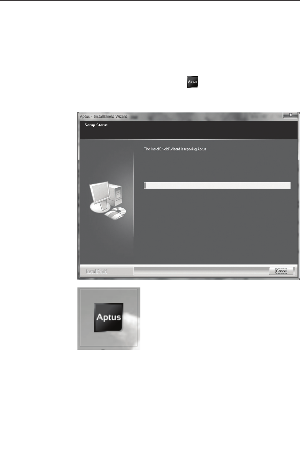
Double click the ‘Aptus Setup.exe’ icon to install Aptus® directly onto your
computer/ laptop. The InstallShield Wizard will guide you through the program
setup process. The installation routine provides an icon on the desktop.
Click the icon to start the software. In addition, Intellian also provides patch les
for software upgrade.
t80W – Marine Satellite TV Antenna System
84
PC to ACU Communication Setup
Starting Aptus®
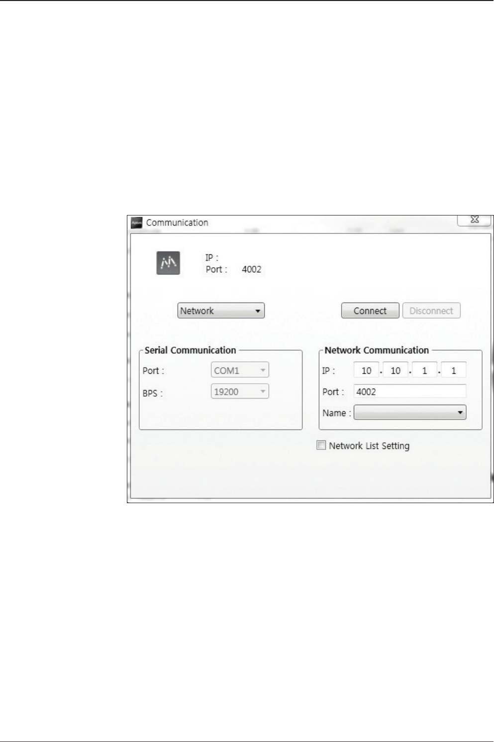
Double-click the Aptus® desktop icon, then Communication Window appears
to establish the data communication between your PC and the ACU. Select
options of connection method to access your ACU either through the Serial Port
Communication or the Network Communication (TCP/IP).
85
Aptus®
Establish a data
communication
Access ACU through Serial Communication
1. Connect a 9 pin Serial cable between the PC INTERFACE connector on
the ACU and the 9 pin Serial port on the PC. (Or you can use a USB cable
to setup Serial connection between a PC and the USB port on the ACU.)
2. Select Serial at communication type combo-box.
3. The baud rate of the ACU is 57600 for the t80W.
4. Select a COM port which is not occupied by other devices.
5. Click the Connect button.
Access ACU through Network Communication (TCP/IP)
1. Connect your PC to the Management Port.
2. Select Network at communication type combo-box.
3. Enter in the ACU’s IP address (Factory default : 192.168.2.1)
4. Enter in the ACU’s port number (Factory default : 4002)
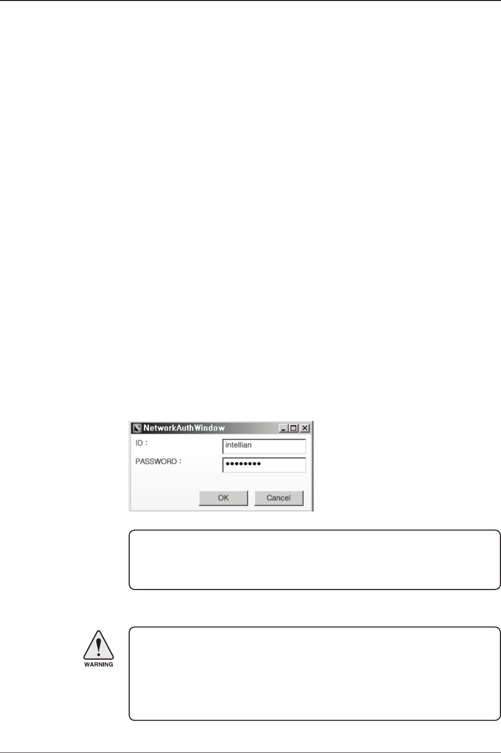
5. Click the Connect button then the Authentication window will appear.
6. Login by using the username and password below:
- Username: intellian (Factory default)
- Password: 12345678 (Factory default)
WARNING:
- Do not plug a USB to the ACU while TCP/IP communication is in use.
Doing so will disable current PC Software Control because the USB
connection has higher priority than TCP/IP connection.
- The amount of data will increase rapidly if Network Communication is in use.
Intellian recommends using Aptus Web to access the ACU.
NOTE: If the remote access PC is located in the same network group with the ACU,
the ACU can be accessed through the internal IP address. But, if the remote access
PC is located outside of the network group, the ACU’s IP address should be changed
to the IP address assigned by the network service provider.
t80W – Marine Satellite TV Antenna System
86
AutoUpdate
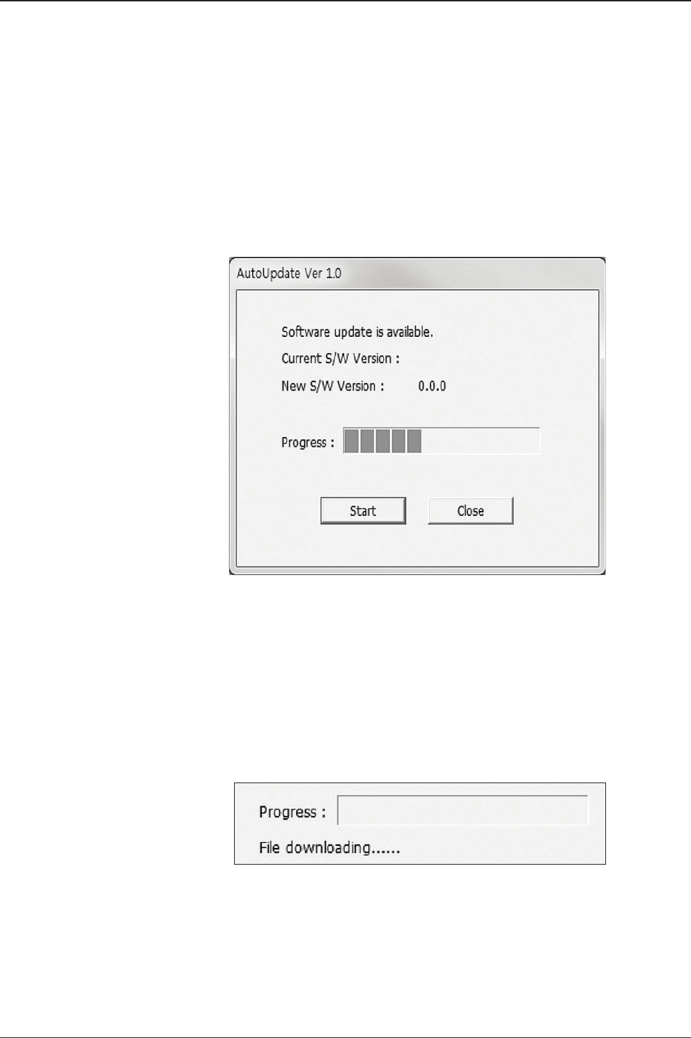
Intellian Aptus® checks and noties the latest version when it is started to maintain
up to date software version by AutoUpdate function.
1. When Aptus® is started, it automatically checks the latest software version from
the server and runs AutoUpdate if new version is available.
2. Current software version information is displayed.
3. It noties new software version information.
4. When you click the “start” button, “File downloading…” message is displayed
while downloading les from the server.
5. When le downloading is nished, “installing…” message is displayed and Aptus
patch runs and the installation starts by InstallShield.
6.Click the “Finish” button when InstallShield installation is nished, then “Run
the Aptus” message is displayed and Aptus runs and AutoUpdate is automatically
nished.
87
Aptus®
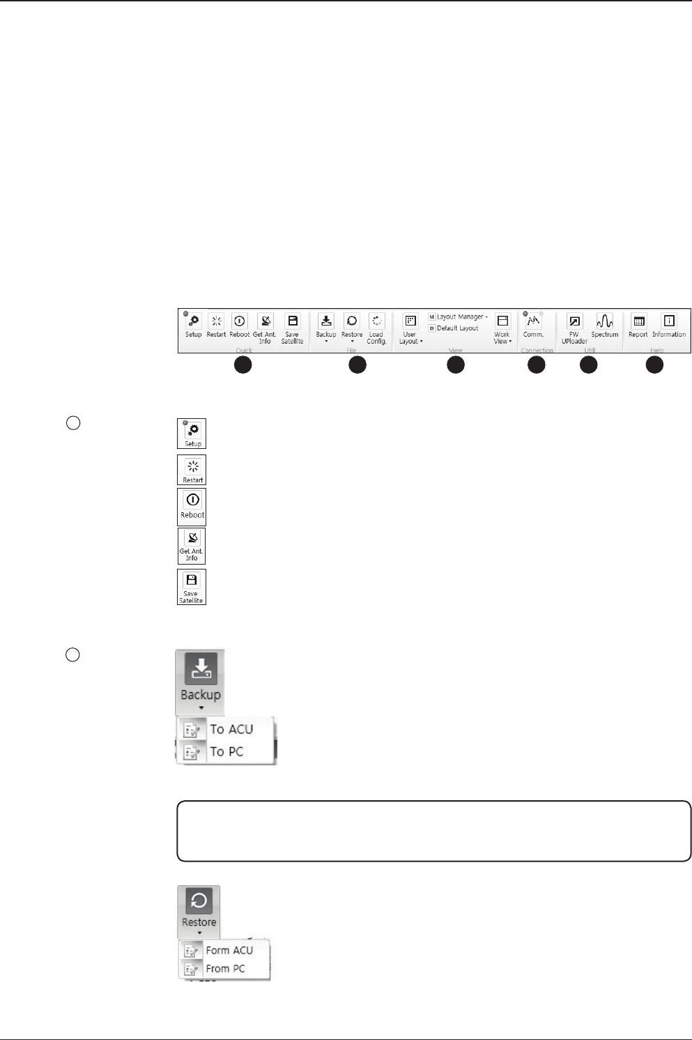
Toolbar Menus
The toolbar menus at the top of the screen display command buttons of the most
commonly used functions of the Aptus®. The toolbar menus consists of 6 main
menus; Quick (for quick launch of functions), File (for le backup, restoring and
loading), View(for user layout and work view), Connection(for communication),
Utill(for rmware uploading and spectrum view) and Help(for reporting problems
and information check) .
Setup: enters Setup mode.
Restart: exits Setup mode and restarts the antenna.
Reboot: reboots the antenna.
Get Ant. Info: obtains the information stored in the antenna
Save Satellite: saves the current bow offset only if the antenna is tracking
onto the satellite. The satellite acquisition time can be reduced signicantly
after the antenna is restarted.
Quick
1
File
2
123 4 5 6
Backup: backups the antenna information to ACU or PC.
- Select ‘To ACU’ to backup the antenna information to ACU.
The backup le (le format: *.ibf) will be stored on the ACU.
- Select ‘To PC’ to backup the antenna information to a PC.
The backup les (le format: *.rpt and *.ibf) will be generated
on the PC.
Restore: restores the antenna by using the stored information in
ACU or PC.
- Select ‘From ACU’ to restore the antenna by using the stored
information in ACU.
- Select ‘From PC’ to restore the antenna by using the stored
information in PC (le format: *.ibf).
NOTE: Both *.rpt and *.ibf les contain antenna information. However, while *.ibf le
can be used for restoring antenna information, *.rpt le is stored as plain-text for viewing
purpose only. Users can open the *.rpt using text editors such as notepad software.
t80W – Marine Satellite TV Antenna System
88
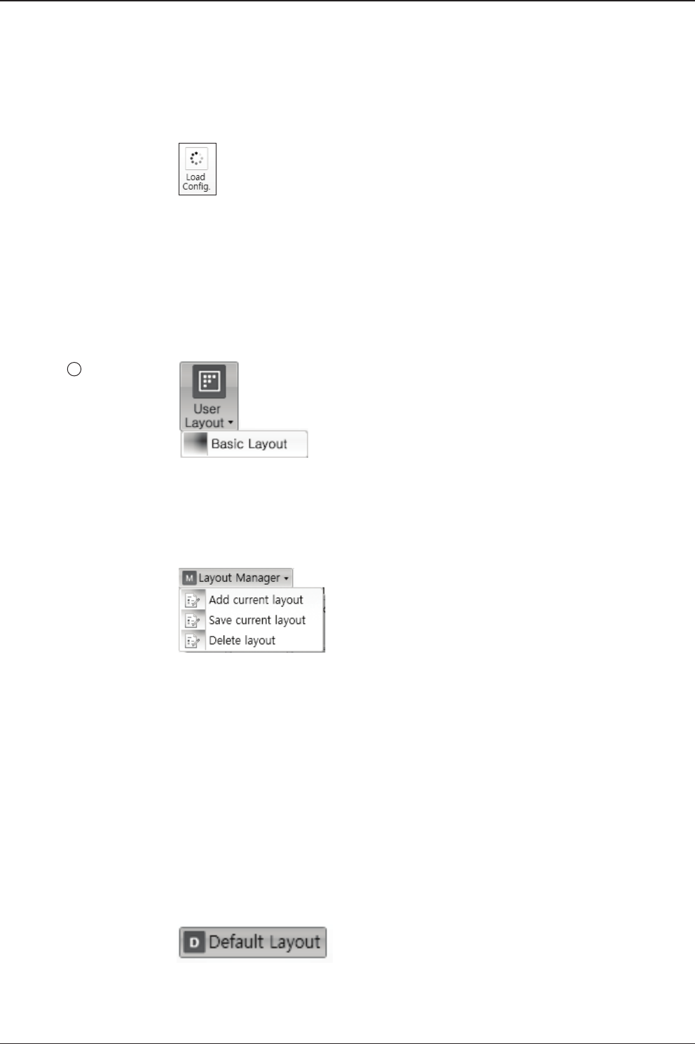
• User Layout: displays the layout list that the user has previously stored by using
Layout Manager. If you select a layout in this list, the selected layout will be
constructed in Work View screen. The ‘Basic layout’ is provided by default.
• Layout Manager: provides the user with add, delete, and save functionalities in
order to manage the user’s layouts.
- Selecting ‘Add current layout’ opens a pop up window. Type in a desired name
of current layout and click Add, then the new name of the current layout will be
saved to the list under User Layout menu.
- When changes are made to the current layout, select ‘Save current layout’ option.
The current layout will be saved with changes.
- To remove a layout, select ‘Delete layout’ option. Select a desired layout to remove
on the pop up window, then click ‘Delete’. Close the window by clicking on ‘Close’.
The selected layout is removed from the User Layout list.
• Default Layout: returns the current layout to the default layout.
View
3
Load Cong. : loads the antenna conguration le (le format: *.cfg).
The conguration le includes the antenna control parameters which are
pre-loaded at the factory and should only be changed by an authorized service
technician. Improper setting of these parameters will cause your system to
perform improperly.
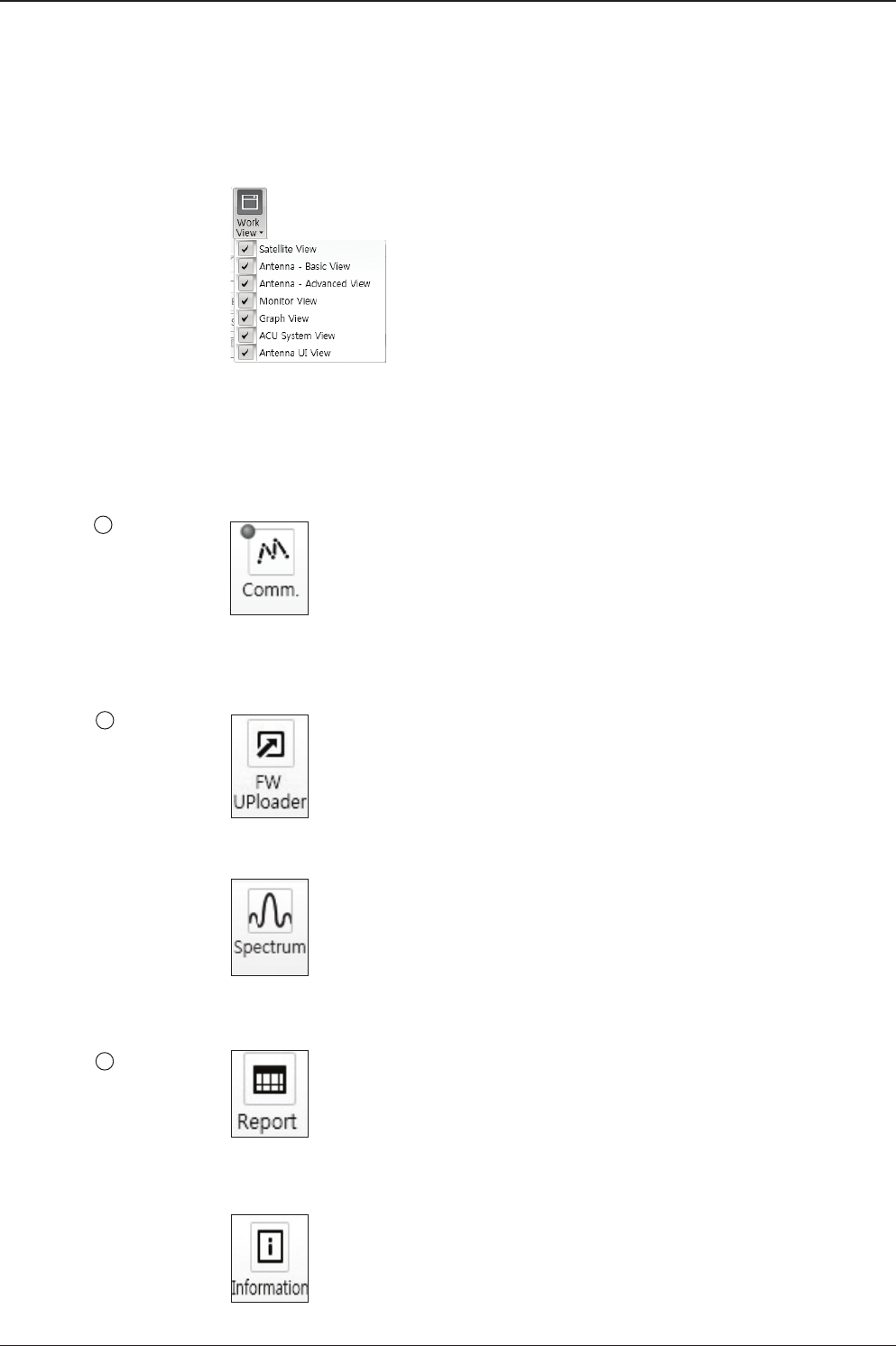
89
Aptus®
Connection
4
Utill
5
Help
6
• Work View: displays a list of seven pre-constructed Work View Tabs (Satellite
View, Antenna Basic View, Antenna Advanced View, Monitor View, Graph View,
ACU System View, and Antenna UI View) and also provides the Activate / Close
functionalities for each view tab. Activate the work view tab by ticking the
checkbox next to it.
At any time, data communication channel can be re-established between Serial
and Network connection. Selecting Comm. Button will display Communication W
indow to connect to the ACU via Serial or Network communication.
• Firmware Uploader: provides the user with the latest rmware version and
updates rmware by simple steps.
• Spectrum: displays current spectrum graph and allows to set spectrum data view
options.
• Report: provides e-mail contact to Intellian technical support team to let the user
report problems at any time.
• Information: displays the information of current Aptus® software version.
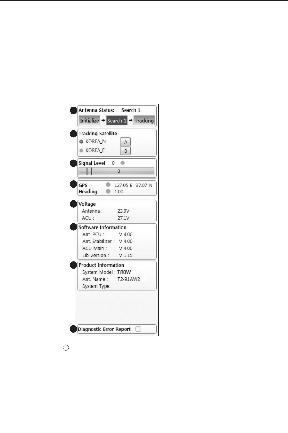
t80W – Marine Satellite TV Antenna System
90
System Property Status Dashboard
The property status dashboard on the left pane of the screen provides the antenna
status, signal level, GPS and heading status, software information, product
information and error status to be monitored quickly.
Antenna Status: Displays the status of the current mode of the antenna.
- Search 1: A Search 1 pattern will automatically be initiated when the ship’s
heading input does not exist or if it fails. The search cycle will repeat until the
antenna receives the lock signal from the receiver or until the DVB transponder
of the target satellite is decoded by the antenna.
- Search 2: A search 2 pattern will automatically be initiated when the AGC falls
below the current threshold setting (indicates that satellite signal has been lost).
Search is conducted in a two-axis pattern consisting of alternate movements in
azimuth (AZ) and elevation. The search cycle will repeat until the antenna
receives the lock signal from the satellite receiver or the DVB transponder of the
target satellite is decoded by the antenna.
1
1
2
3
4
5
6
7
8
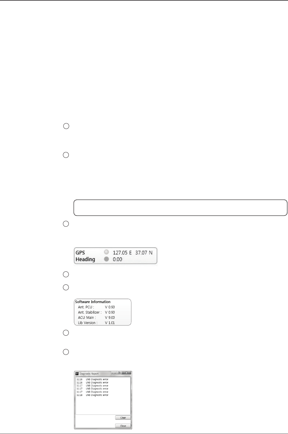
91
Aptus®
Tracking Satellite
Display or set current tracking satellite and tracking information. Up to three
satellites can be selected.
2
- Search 3: Search 3 pattern will automatically be initiated when AGC falls below
the current tracking level threshold value. Once the desired signal is found and
above the predened tracking threshold, the ACU will enter to tracking mode.
- Tracking: Antenna is tracking the target satellite.
- Initialize: Antenna or ACU is initializing.
- Setup: Antenna is in SETUP mode.
Signal Level
Shows “DVB” when DVB mode of tracking signal is in use. The “Red” line indicates
the signal “Detect Level Threshold” and the “Orange” line indicates the signal
“Tracking Level Threshold”. If the signal level is higher than the tracking level
threshold, the signal level bar will display “Blue” color. If the signal level is lower
than the tracking level threshold, the signal level bar will display “Orange” color and
the antenna will stay in searching mode.
NOTE: If the signal level is not higher than the tracking threshold, decrease the detect
and tracking level.
GPS and Heading
Displays the current GPS location from the Antenna and Ship’s heading information.
The status light ashes green if the system receives a correct input of the GPS and
Ship’s heading.
Voltage: Displays the antenna and the ACU voltage information.
Software Information: Displays the antenna and the ACU rmware versions, and the
library version.
Product Information: Displays the antenna and ACU serial numbers, antenna model
and ACU model.
Diagnostic Error Report
The square button next to the Diagnostic Error Report turns red when the system
receives an error. Click the button to see a Diagnostic Report.
3
4
6
5
7
8

t80W – Marine Satellite TV Antenna System
92
Work View Tabs
Aptus® provides seven Work View Tabs (Satellite View, Antenna Basic View,
Antenna Advanced View, Monitor View, Graph View, ACU System View, and
Satellite View) to manage the Antenna and the Satellite conguration.
How to modify the settings on Work View;
1. Enter the Setup mode by clicking Setup icon.
2. Tick the checkbox next to the “Set” button to modify the settings.
3. Enter the desired value then press the Set button to save the settings.
1. Antenna – Basic Info.
This view tab provides information on the Antenna’s Current GPS location, Head-
ing Device, Bow Information, Skew Information, and the Antenna’s Angle. This
view tab uses the Antenna’s AZ and EL information as well as the Ship’s Heading
information in order to provide a dynamic graphic user interface (UI).

93
Aptus®
- GPS: displays and sets current antenna’s GPS.
- Heading: displays and sets current ship’s heading information.
· Heading Device: None / NMEA/ NMEA 2000/Ground Test.
The baud rate (4800/ 9600/ 19200/ 38400) must be set if NMEA is selected.
- Bow Information: displays and sets current antenna’s bow.
- Skew Information: displays current antenna’s skew and skew offset for the
selected satellites.
· Pol Sensor Calibration: calibrates the sensor (potentiometer).
- Find Antenna Angle: displays and sets the current antenna angle. Select a desired
satellite from the drop-down menu, then longitude, azimuth, elevation and skew
information are displayed.
· Find Angles & Skew Antenna GPS: Finds the current antenna angles and
skew angle in relation to the longitude (orbit position) of the antenna's
current GPS.
- Antenna Angle: displays and sets current antenna’s absolute and relative AZ
(azimuth) position, EL (elevation) position and polarization (between Linear and
Circular). You can move antenna azimuth and elevation position and LNB Pol
angle by using the arrows or inputting a value to nd the desired satellite manually.
- Go to Position: The current position (angle) of the antenna is displayed.
Push the “Go to target Position” button after keying in the desired angle to move
the antenna to target position.
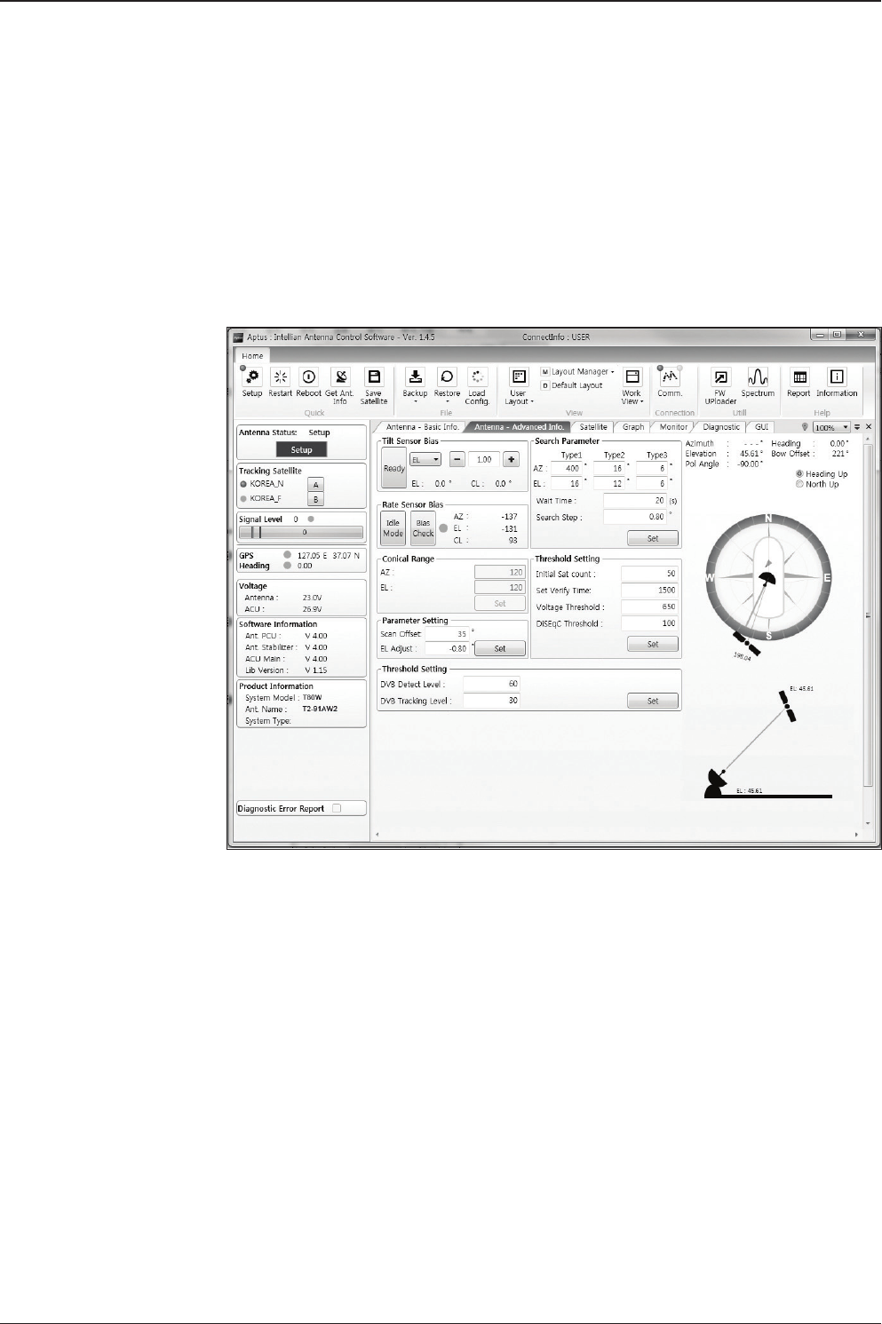
t80W – Marine Satellite TV Antenna System
94
2. Antenna – Advanced Info.
This view provides information on the Tilt Sensor Bias, Rate Sensor, Conical
Range, Parameter Setting, Threshold Setting, Search Parameter and Flag Setting.
-Tilt Sensor Bias: This maintains the elevation and the cross level axes
in order to keep the pedestal parallel to the horizon. Adjust the two solid-
state tilt sensors to provide absolute cross-level tilt of the antenna and el
evation feedback to eliminate long-term pointing drift (error). Tilt bias
must be adjusted when the antenna control board or sensor box is
replaced. If the bubble on the button level located on the sensor box is
not centered, follow the following steps to adjust the tilt sensor bias.
· Step 1. Enter Setup mode and press the “Ready” button to bring
the elevation and cross-level to 0.
· Step 2. Select “EL” from the drop down list and press Up and
Down arrow keys to adjust the bubble until it is located in the
center ring of the button level.
· Step 3. Select “CL” from the drop down list and press Up and
Down arrow keys to adjust the bubble until it is located in the
center ring of the button level.

95
Aptus®
· Step 4. Press the “Restart” icon to restart the antenna.
- Rate Sensor: is used to calibrate the DC voltage output from the three rate sen-
sors (azimuth, elevation, and cross-level). These are used to sense antenna motion
that corresponds to the ship’s motion (roll, pitch, and yaw) for stabilizing the ped-
estal. The DC voltage output from each of the rate sensors may vary by an amount
which is directly proportional to the direction and rate of motion induced on it.
Before calibrating the rate sensors located in the Sensor box, make sure that the
antenna is placed on a rigid and at platform. During the calibration process, any
motion of the antenna should be avoided as it can affect the antenna’s perfor-
mance. Proceed with the following steps to perform the calibration.
· Step 1. Enter Setup mode
· Step 2. Press the “Idle Mode” button to release the elevation and
cross level motor brakes while the antenna is in Setup mode.
· Step 3. Check whether or not the bubble is located at the center
of the button level. If not, move it to the center by following the
previous instruction of Tilt Sensor Bias adjustment.
· Step 4. Press the “Bias Check” button to calibrate the rate sensor.
A blue circle will be displayed next to the Bias Check button if the
calibration is completed. A red circle will be displayed if calibration
failed. A green circle will be displayed during the calibration
process.
- Parameter Setting: used to set the control parameter settings.
· Scan Offset: The scan offset is to offset the angle difference
between the black marker on the sub-reector and the optical
sensor
· EL Adjust: The elevation adjustment is to offset the angle
difference between the mechanical elevation angle and actual
elevation angle.

t80W – Marine Satellite TV Antenna System
96
- Threshold Setting: set the threshold level for detecting and tracking the satellite
signal.
· DVB Detect Level: displays and sets signal detection threshold
level when DVB tracking mode is in use.
· DVB Tracking Level: displays and sets signal tracking threshold
level when DVB tracking mode is in use.
- Search Parameter:
· Wait time: set the time-out for automatic initiation of a search after
the signal level drops below the pre-dened threshold value.
· Search Step: set increment step size.
· Type 1, Type 2 & Type 3 (Search 1, 2 & 3) Range: set Search 1, 2 & 3
search range. Search 2 and Search 3 are conducted in a two-axis
pattern consisting of alternate movements in azimuth and elevation as it
forms an expanding square.
- Threshold Settings
· Initial Sat Count: Set the threshold count for maintaining tracking.
· WRS Detect Level: Set the WRS detection level.
· Voltage Threshold: Set the voltage threshold. The voltage threshold is to
distinguish the voltage between 13V and 18V.
· DiSEqC Threshold: Set the DiSEqC threshold. The DiSEqC threshold is
to distinguish the 0KHz tone and 22KHz tone.
- Flag Settings
· Use WRS Method: Use WRS method is to determine whether the system
uses “WRS Detect Level” or not. Use WRS method and “WRS Detect
Level” are pair functions.
· Use Offset Difference: Use offset difference is to determine whether the
system uses “Offset Difference” or not. Use Offset Difference and “Offset
Difference” are pair functions.

97
Aptus®
3. Satellite (Satellite View)
The name, longitude, Skew Offset, Polarity, verication method of the satelite
and local frequency are displayed. Tick the “Edit Satellite” box to edit the satellite
information. After modifying the value.
- LNB Local Frequency: Displays or sets LNB local frequency and its corre-
sponding LNB voltage supplied. You may select pre-programmed LNB LO settings
from the drop down list. This procedure is same for both the Intellian Global VSAT
PLL LNB and any other LNB.
- Transponder Information
· Register for Sat A & Register for Sat B: register the selected satellite for
A or B.
· Transponder information consists of frequency, symbol and NID
(Network ID) of a transponder in tracking the satellite. There are four
groups of transponder information. ‘Vertical/RHCP’ is applied when the
IRD supplies 13V, and ‘Horizontal/LHCP’ is applied when the IRD
supplies 18V. ‘LOW’ is applied when DiSEqC signal is not detected from
IRD. ‘HIGH’ is applied when the DiSEqC signal is detected from the IRD.
After modifying information, press the ‘Edit Satellite Information’ button,
then new information is updated in the antenna.

t80W – Marine Satellite TV Antenna System
98
- Pol & Band Control: The “Pol” controls 13V (Vertical/RHCP band) or 18V
(Horizontal/ LHCP band). The “Band” controls DiSEqC 0KHz tone (Low band) and
22KHz tone (High band). After modifying information, press ‘Edit Satellite Informa-
tion’ button, then new information is updated in the antenna.
- Triple Satellite Mode: To select between Dual-Sat mode and Triple-Sat mode,
tick the 'Dual Satellite Mode' box or 'Triple Satellite Mode' box at the bottom of
the screen.
- Edit Satellite Information: push the “Edit Satellite Information” button to update
the information after modifying values.
- Load Default: Push the "Load Default" button to select a regional library le *.rif
according to your region.
- Update Default: After loading a regional library le *.rif, push the "Update De-
fault" button to update the system.
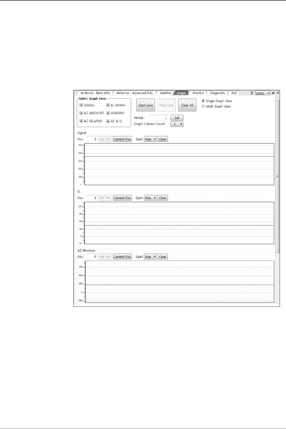
99
Aptus®
4. Graph View
This view provides information on Signal, Elevation (EL), Absolute AZ (Azimuth),
Relative AZ, Heading, AZ and EL in Single or Multi graph formats.
- Select Graph Item: shows the graphs of only the checked item(s) in a
Single or Multi Graph View.
- Single Graph View: shows Graph Views per each single Graph Item
selected in ‘Select Graph Item’.
- Multi Graph View: shows one large integrated Graph View of multiple
Graph Items selected in ‘Select Graph Item’.
- Start/Stop Save: the chosen item is saved within the data log. The data
log which stores the information displayed in the graphs can be later
used for a service technician to nd out a cause of any possible problem
to the antenna.
- Clear All: clears everything drawn on the Graph View window.
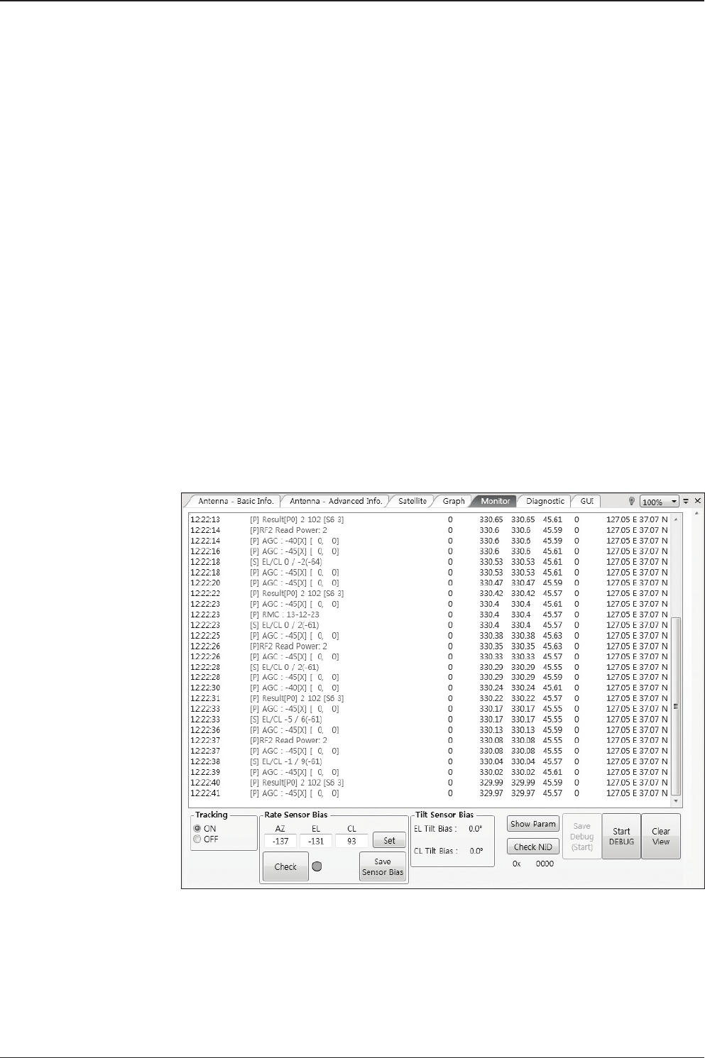
t80W – Marine Satellite TV Antenna System
100
5. Monitor
This view provides a UI which can monitor all data that has been received from the
ACU.
- Tracking: turns on or off the dish scan function. If the dish scan function
is disabled, the antenna will stop adjusting the antenna pointing angle in
order to optimize the receive signal level.
- Set Pos.: sets the current position as center value of each Graph Item.
- Current Pos.: moves to the location according to values of each Graph Item.
- Span: sets the Display Range(s) of each corresponding Graph Item.
- Period: displays and sets the signal sampling rate.
- Graph Column Count: makes all Graph Views show in either one or
two-column format.

101
Aptus®
- Rate Sensor Bias: is used to calibrate the DC voltage output from the
three rate sensors (azimuth, elevation, and cross-level). These are used
to sense antenna motion that corresponds to the ship’s motion ( roll,
pitch, and yaw) for stabilizing the pedestal. Push the "Check" button to check the
EL and CL Tilt Bias.
- Show Param: shows the current antenna parameters.
- Check NID: veries the NID (network ID) of the current tracking tran
sponder. Press the NID button to obtain the NID only if the antenna is
locked onto the desired satellite .
- Debug (Start): starts the debug log of the antenna. The debug message
will be displayed once the debug button is pressed.
- Stop Debug: stops debug logging of the antenna.
- Save Debug (Start/Stop): starts or stops saving the debug log. This button is
enabled once the Start Debug button is pressed.
- Clear View: clears the debug message or log data in monitoring window.
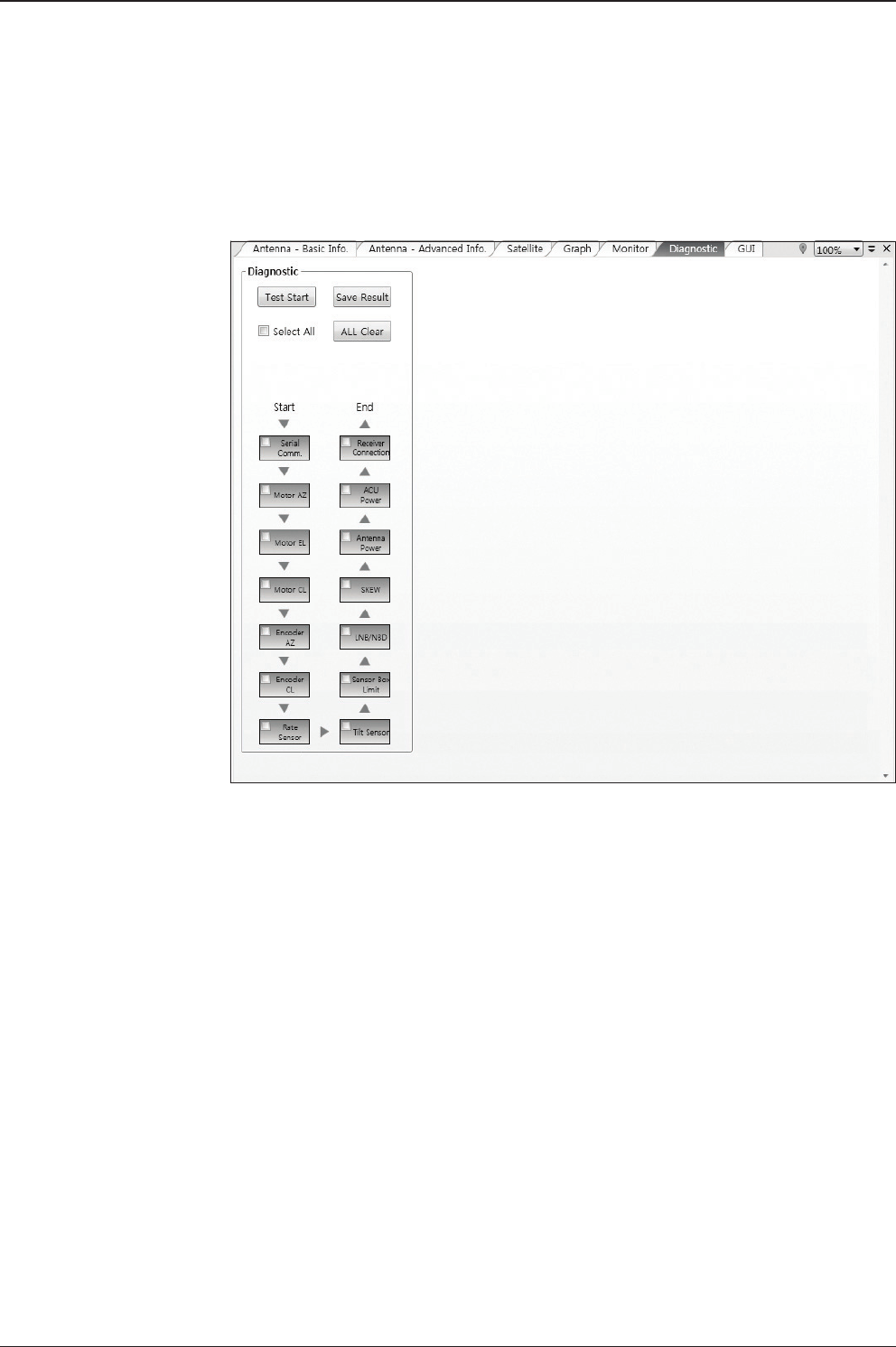
t80W – Marine Satellite TV Antenna System
102
6. ACU System
This view provides Antenna Diagnostic Testing.
- Diagnostic : select to run a full diagnostic test or single diagnostic test.
"Green" indicator is displayed for the test under progress. "Blue"
indicates the test result as Pass while "Red" indicates the result as Fail.
"Yellow" indicates the test has been skipped.
• Serial Comm.: tests the data communication between the antenna and
the ACU.
• Motor AZ: tests the azimuth motor.
• Motor EL: tests the elevation motor.
• Motor CL: tests the cross-level motor.
• Encoder AZ: tests the azimuth encoder.
• Encoder CL: tests the cross-level encoder.
• Rate sensor: tests the rate sensor.
• Tilt Sensor: tests the tilt sensor.
• Sensor Box Limit: tests the sensor box motor.
• LNB/ NBD: tests the LNB. (NBD is not available on this model.)
• Skew: tests the LNB skew motor.

103
Aptus®
• Antenna power: tests the antenna power to see whether or not it is
within the nominal operating range.
• ACU power: tests the ACU power to see whether or not it is within the
nominal operating range.
• Receiver Connection: tests the data communication between the
antenna and the receiver.
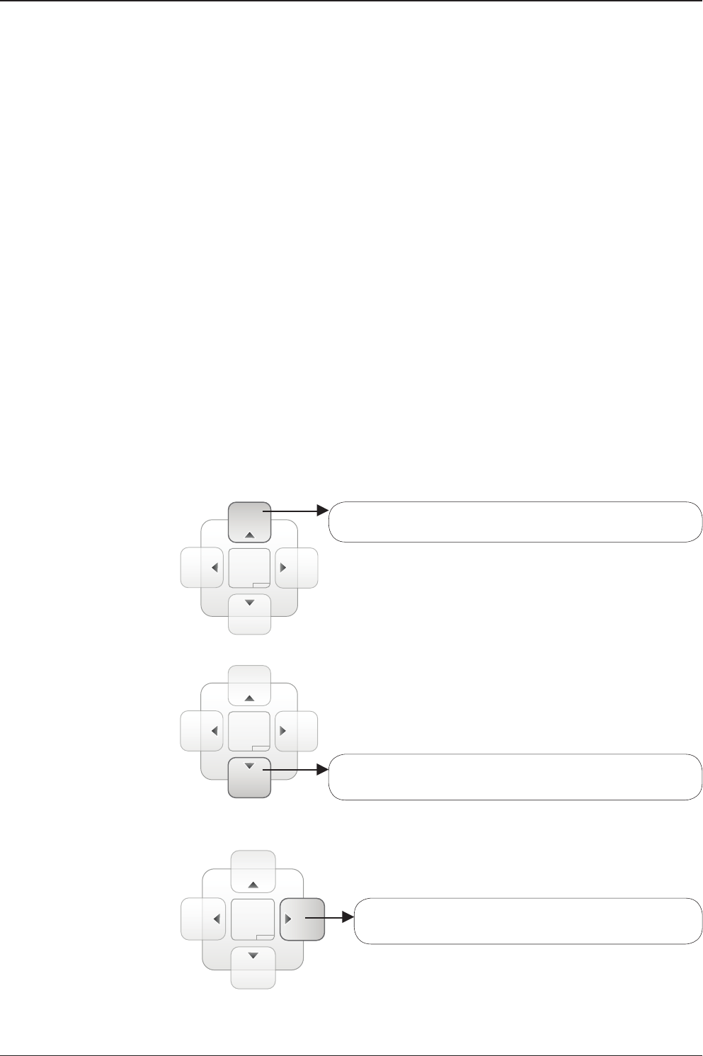
t80W – Marine Satellite TV Antenna System
104
7. Work View Functions
The seven Work View Tabs displayed in the Work View can be arranged in cus-
tomized layouts.
- Layout Formatting
· Each of the Work View Tab can be separated from the rest Tabs.
Click and hold the left mouse button on the Work View Tab’s
header and then drag a desired Tab out. When a Work View Tab
is separated from the rest of your Work View Tabs, again click
and hold the left mouse button on the Work View Tab’s header to
display a cross-shaped Navigator icon. While holding the mouse
button, bring the selected Work View Tab closer to the Navigator
icon and release the mouse button at your desired position (top,
left, right or bottom arrow). This time, the selected Tab will be
moved to the desired position.
Move the selected Work View Tab to the top position of the
Work View layout.
Move the selected Work View Tab to the right position of
the Work View layout.
Move the selected Work View Tab to the bottom position of
the Work View layout.
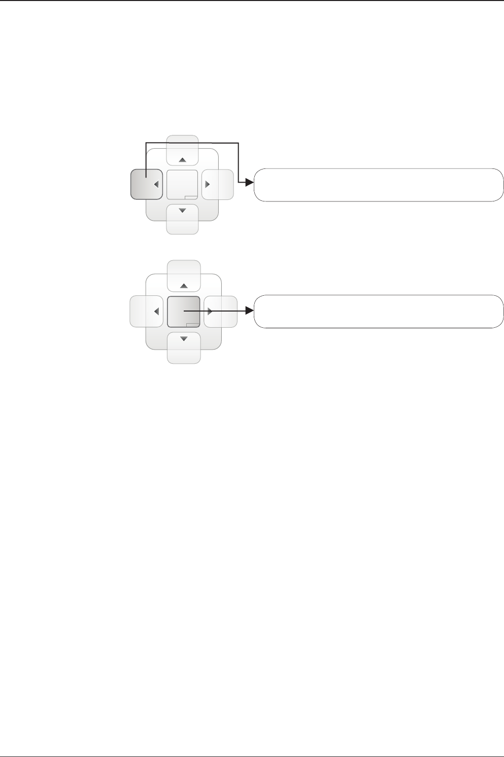
105
Aptus®
Move the selected Work View Tab to the left position of
the Work View layout.
Move the selected Work View Tab to the center position
of the Work View layout.
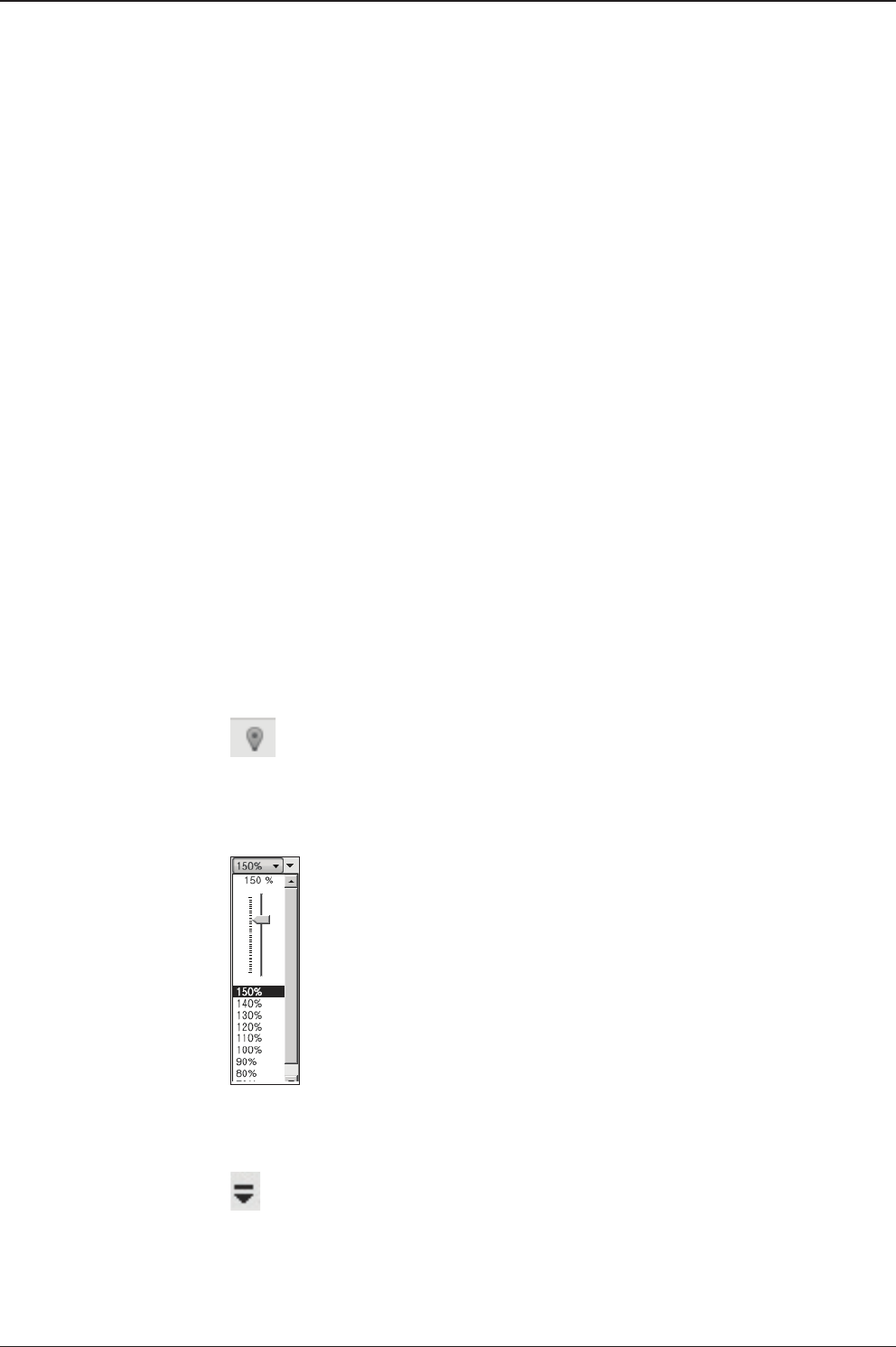
t80W – Marine Satellite TV Antenna System
106
- Horizontal or Vertical Tab Group
The Work View Tabs can be also aligned horizontally or vertically. Without
dragging them out, right-click the mouse button on a desired Tab header
and select ‘New Horizontal Tab Group’ or ‘New Vertical Tab Group’
option. Selecting ‘New Horizontal Tab Group’ will separate a selected Tab
from the rest of other Tabs then arrange it in a horizontal format. Likewise,
selecting ‘New Vertical Tab Group’ will separate a selected Tab from the
rest of other Tabs then arrange it in a vertical format.
- Closing the Work View Tab
To close the Work View Tab, right-click the mouse button on a desired
Tab header and select ‘Close’ option in the drop down list. To close all
Work View Tabs except the selected Tab, select ‘Close All But This’
option in the drop down list.
- Zoom Tool
Using the Zoom tool, you can easily select the magnication you want by
using Zoom In and Zoom Out bar, and Fit in Work View button.
Fit Work View Button: ts the current view to the Work View window size. The but-
ton toggles between the t view and the previous view.
Zoom In and Zoom Out Bar: zooms in and out to expand and reduce the View to
the desired size. (The zoom changes in 10% increments.)
View Switch Button: displays a list of the current views in a list. Choosing one of
these views will display the selected view in the Work View window.

107
Aptus®
View Name Button: displays the current Work View name.
Close View Button: closes the current view.

t80W – Marine Satellite TV Antenna System
108

109
APTUS WEB
APTUS WEB
Introduction
Main Page
Page Login
Top menus
Dash Board & Information
Antenna Settings
Ship setting
Antenna Position & Parameters
Tracking setting
Diagnostic
Firmware & Conguration
Antenna Firmware Upgrade
Antenna Log
Antenna Backup & Restore
Administration
Network Setting
SNMP Setting
User Management
iARM Upgrade
iARM Save & Reboot
Antenna Event Log
Intellian Network Devices
t80W – Marine Satellite TV Antenna System
110
Introduction
With embedded Aptus Web, the t80W can be monitored, controlled, and diagnosed
remotely from anywhere, anytime through the TCP/IP protocol. This not only can
save time but also save the cost generated from routine maintenance activities such
as operating rmware upgrades, tracking parameters resets, and system diagnostic.
How to access Aptus Web
1. Connect an Ethernet Cable between your PC and the Management Ethernet Port.
2. Enter the ACU's IP address (192.168.2.1) into your web browser's address bar to
login into the ACU’s internal HTML page, if this system has not been changed from
the ACU’s factory default.
NOTE: Aptus Web can be displayed in Internet Explorer 7 or later and is also compatible
with Firefox and Chrome web browsers.

111
APTUS WEB
Page Login
1. Choose either to Control & Monitor the ACU (Control & Monitoring) or Only
Monitor the ACU (Monitoring Only).
2. Log into the ACU by typing in User Name and Password information. If this
system has not been changed from the factory default:
• User Name: intellian
• Password: 12345678
WARNING: The Control & Monitoring Mode will be switched to the Monitoring
Only Mode in the following cases;
• If PC Software (Aptus) is connected using TCP/IP Communication while
APTUS WEB Control is in use.
• If APTUS WEB Control & Monitoring Mode is accessed while PC Software
is running via TCP/IP Communication. In this case, the web page
will display a pop-up message asking if you want to disconnect the PC
Software network connection. If you select ‘No’, the Control & Monitoring
Mode will be switched to the Monitoring Only Mode.
Main Page
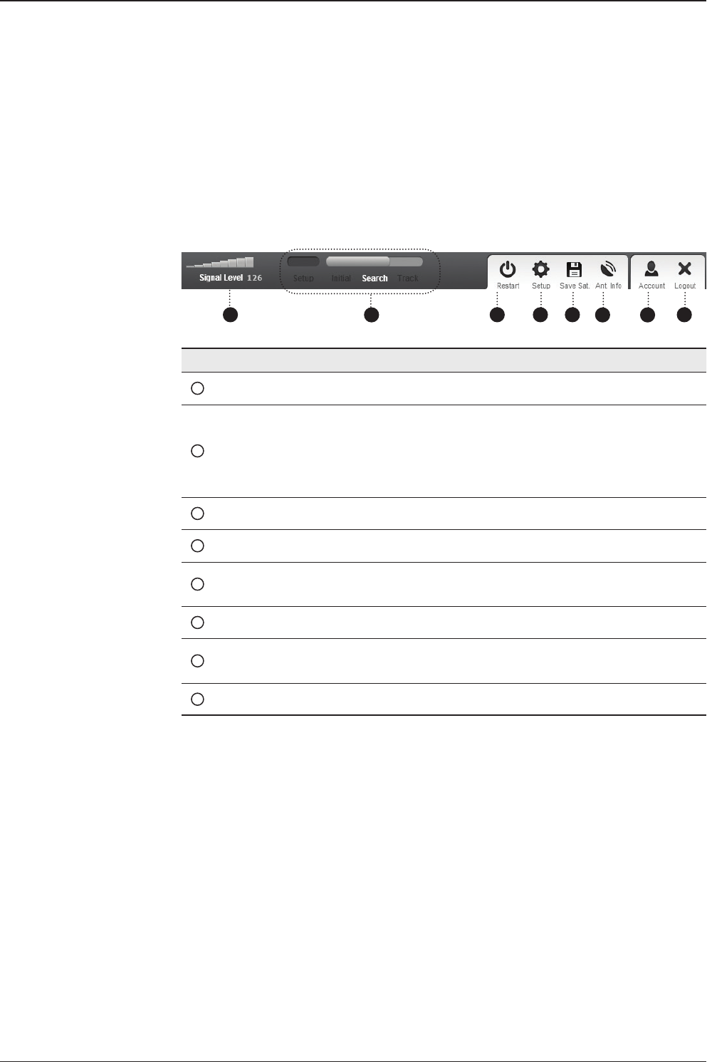
t80W – Marine Satellite TV Antenna System
112
No. Item Description
1Signal Level Display current signal level.
2Antenna
status
- Setup: Displays whether or not the antenna is in SETUP
mode. The indicator shows “Blue” in the SETUP mode.
- Initial: Antenna or ACU is initialized.
- Search: Antenna is searching a target satellite.
- Track: Antenna is tracking the target satellite.
3Restart Restart the antenna system.
4Setup Enter SETUP mode.
5Save Sat. Save current satellite settings.
Bow offset will be adjusted and saved automatically.
6Ant. Info Obtain current antenna information.
7Account Shortcut to User Management menu. Change login ID and
Password.
8Logout Logout the ACU's internal HTML page.
Top Menus
Once you log in, the following information and menus are displayed.
1 3 4 5 678
2
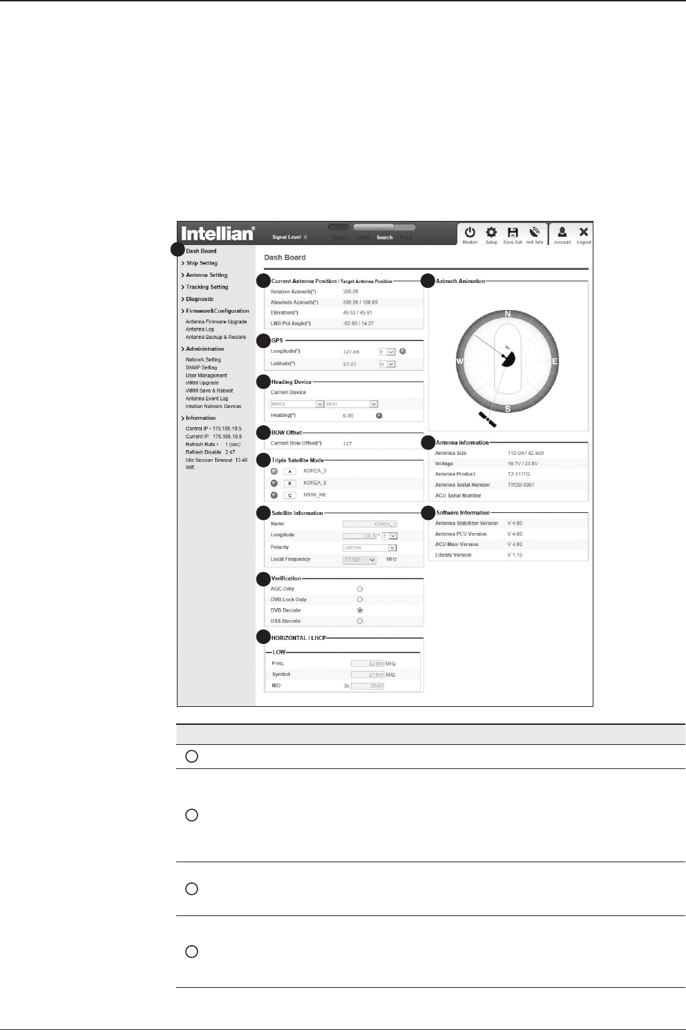
113
APTUS WEB
No. Item Description
1Dash Board Displays current antenna status to be quickly monitored.
2
Current Antenna
Position /
Target Antenna
Position
Displays current antenna position.
- Relative Azimuth: displays antenna relative AZ angle.
- Absolute Azimuth: displays antenna absolute AZ angle.
- Elevation: displays antenna elevation angle.
- LNB Pol Angle: displays LNB pol angle.
3GPS
Displays current GPS information.
- Longitude (East / West)
- Latitude (North / South)
4Heading
Device
Displays current Heading Device: NONE, NMEA, NMEA 2000,
Ground test If the ship’s gyrocompass input is other than NMEA
separate purchase of NMEA Converter is required.
- Heading: displays ship’s heading information.
Dash Board & Information
On the left side of the page, Dash Board and Information menus are displayed
as below to provide quick monitoring of the antenna status and settings. Other
menus are displayed only in the Control & Monitoring mode and their functions will
be described in the next sections.
1
3
4
5
6
7
8
9
10
11
12
2

t80W – Marine Satellite TV Antenna System
114
5BOW Offset Display current bow offset
6Triple Satellite
Mode Mode: Select between Dual-Sat mode and Triple Sat mode.
7Satellite
Information
Displays the satellite name, longitude, polarity and LNB local
frequency of the current satellite.
8Verication Displays current verication method for satellite tracking.
9
Tracking
Information
(Frequency band)
Displays current frequency band that consists of frequency, symbol
and NID (Network ID) of a transponder in tracking the satellite.
10 Azimuth
Animation
Shows a graphical representation of the current antenna position
to identify whether or not the antenna is aligned properly to the
target satellite or is in a block zone.
11 Antenna
Information Displays the product information
12 Software
Information
Displays current Antenna and ACU rmware versions and Satellite
Library version installed in the system.
- Antenna Stabilizer Version
- Antenna PCU Version
- ACU Main Version
- Library Version
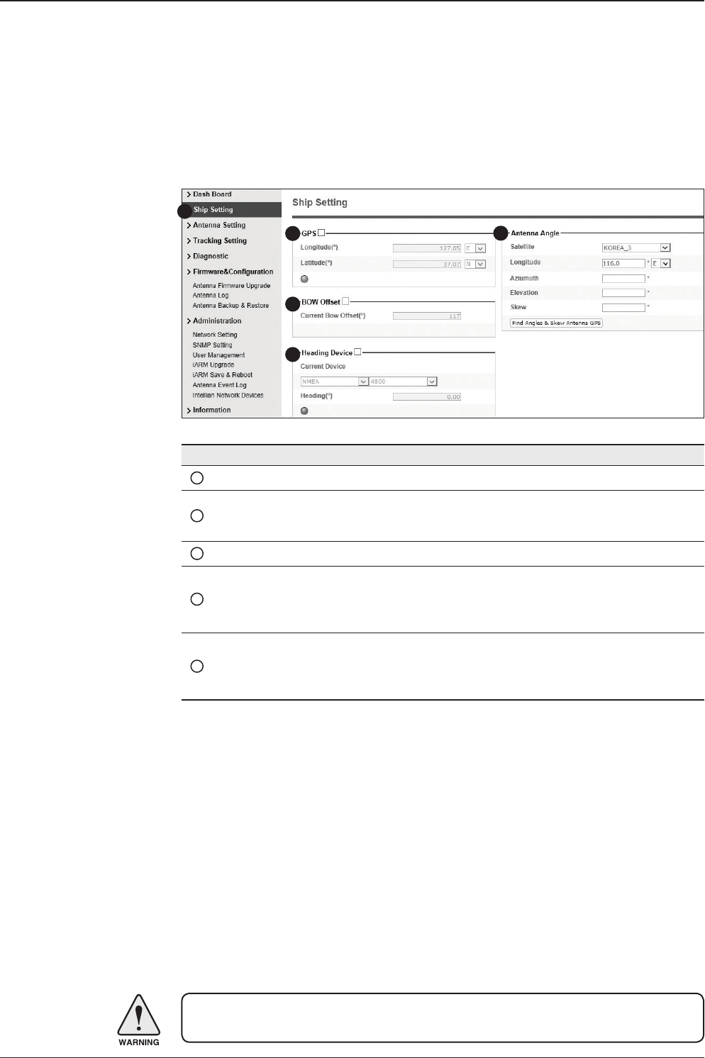
115
APTUS WEB
No. Item Description
1Ship Setting Set the ship information and nd antenna angle.
2GPS
Set GPS information.
- Longitude (East/West)
- Latitude (North/South)
3Bow Offset Set Bow Offset if needed.
4Heading Device Set ship’s heading device (NONE, NMEA, NMEA2000,
Ground Test) and ship’s heading information
5Antenna Angle
Find the current antenna angles and skew angle in relation to
the longitude (orbit position) of the antenna's current GPS.
Click 'Find Angles & Skew Antenna GPS' button.
WARNING: Enter the SETUP mode for conguration. Tick the checkbox before
modifying the settings. After conguration, click ‘Set ...’ button to submit the settings.
Ship Setting
Antenna Settings
1
3
4
52
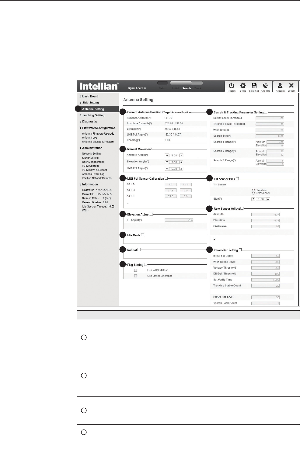
t80W – Marine Satellite TV Antenna System
116
Antenna Position & Parameters
No. Item Description
1Antenna Setting
Set current antenna position and Search and Track-
ing parameters. These parameters should only be
changed by an authorized service technician. Im-
proper setting of these parameters will render your
system inoperable.
2Current Antenna Position/
Target Antenna Position
Display current antenna position.
-
Relative Azimuth: display antenna relative AZ angle.
-
Absolute Azimuth: display antenna absolute AZ angle.
- Elevation: display antenna elevation angle.
- LNB Pol Angle: display LNB pol angle.
- Heading: display ship’s heading information.
3Manual Movement
Move antenna azimuth and elevation angles and
LNB pol angle to nd the desired satellite manually.
LNB Pol Angel can be adjusted at any time either in
SETUP Mode or Tracking Mode.
4LNB Pol Sensor Calibration Calibrate the LNB pol angle when the control board,
potentiometer or LNB Assembly is replaced.
1
3
4
5
6
7
8
9
10
11
12
2

117
APTUS WEB
5Elevation Adjust Adjust the elevation to offset the angle difference between
the mechanical elevation angle and actual elevation angle.
6Idle Mode
Release the elevation and cross level motor brakes while
the antenna is in SETUP mode. The antenna can be
moved manually during the mode.
7Reboot Reboot the system.
8Flag Setting
Set the ag settings. Select 'Use WRS Method' to use
'WRS(Wide Range Search) Detect Level'. Select 'Use
Offset Difference' to enable the system to offset the signal
difference between RHCP and LHCP.
9Search & Tracking
Parameter Setting
- Detect Level Threshold: display / set current detect level
threshold to set the satellite signal detection level.
- Tracking Level Threshold: display /set current tracking
level threshold to set the satellite signal tracking level.
- Wait Time: set the time-out for automatic initiation of a
search after the signal level drops below the pre-dened
threshold value.
- Search Step: set increment step size
- Search 2 Range: is reserved for future use
- Search 1 Range: set Search 1 search range. The antenna
is detecting the satellite signal which is above the current
detect level threshold. The search range corresponds to
Search Type 1. Once the signal is located, the antenna will
enter to “Search 3 mode”.
- Search 3 Range: set Search 3 search range. The antenna
is detecting the satellite signal which is
above current tracking level threshold. The search range
corresponds to Search Type 3. Once the signal is located,
the antenna will enter “Tracking mode”.
10 Tilt Sensor Bias
Adjust the two solid-state tilt sensors used to provide
absolute cross-level tilt of the antenna and elevation feed-
back to eliminate long-term pointing drift (error). Tilt bias
is required to be adjusted when the antenna control board
or sensor box is replaced. Check to see whether or not the
bubble is located at the center of the level vial.
11 Rate Sensor Adjust
Calibrate DC voltage output from the three rate sen-
sors used to sense antenna motion in azimuth, elevation
and cross-level axes. During the calibration process, the
antenna should avoid any motion as it can affect the an-
tenna’s performance.

t80W – Marine Satellite TV Antenna System
118
WARNING: Tick the checkbox before modifying the settings. After conguration, click
'set...' button to submit the settings.
12 Parameter Setting
- Initial Sat Count: Set the threshold count for maintaining
tracking.
- WRS Detect Level: Set the WRS detection level.
- Voltage Threshold: Set the voltage threshold. The voltage
threshold is to distinguish the voltage between 13 V and
18V.
- DiSEqC Threshold: Set the DiSEqC threshold.
The DiSEqC threshold is to distinguish the 0KHz tone
and 22 KHz tone.
- Sat Verify Time: Set the threshold count for the satellite
verication.
- Tracking Stable Count: Set the threshold count for
stabilizing the satellite before tracking.
- Offset Diff AZ-EL: Set the offset difference between
Azimuth and Elevation range.
- Search Lock Count: Set the threshold count for locking
on the satellite before tracking.
- Offset Diff RH-LH: Set the offset difference between
RHCP and LHCP signals.
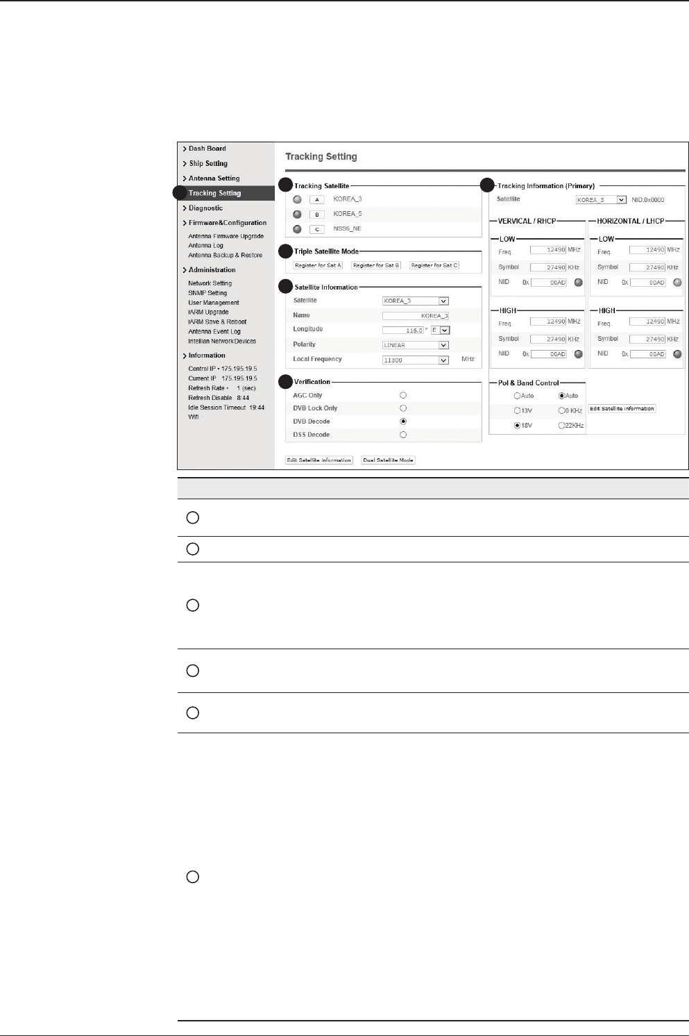
119
APTUS WEB
Tracking Setting
No. Item Description
1Tracking Setting Display or set current tracking satellite and tracking
information.
2Tracking Satellite Select the tracking satellite.
3Triple Satellite Mode
Register the selected satellite in Tracking Satel-
lite for Sat A, Sat B or Sat C. To select between
Dual-Sat mode and Triple-Sat mode, press the 'Dual
Satellite Mode' button or 'Triple Satellite Mode' but-
ton on the bottom of the screen.
4Satellite Information Set the satellite name, longitude, polarization and
local frequency of LNB to be used.
5Verication Set the verication type for satellite tracking (AGC
Only, DVB Lock Only, DVB Decode, DSS Decode)
6Tracking Information
Tracking information consists of frequency, symbol
and NID (Network ID) of a transponder in tracking
satellite. There are four groups of tracking informa-
tion. “Vertical/RHCP” is applied when IRD supply
13V, and “Horizontal/LHCP” is applied when IRD
supply 18V. “LOW” is applied when DiSEqC signal
(0 kHz tone) is not detected from IRD. “HIGH” is ap-
plied when DiSEqC signal (22 kHz tone) is detected
from IRD.
Pol & Band Control: The “Pol” controls 13V (Vertical/
RHCP band) or 18V (Horizontal/ LHCP band). The
“Band” controls DiSEqC 0KHz tone (Low band) and
22KHz tone (High band)
After modifying information, press ‘Edit Satellite In-
formation’ button, then new information is updated
in the antenna.
1
3
4
5
6
2
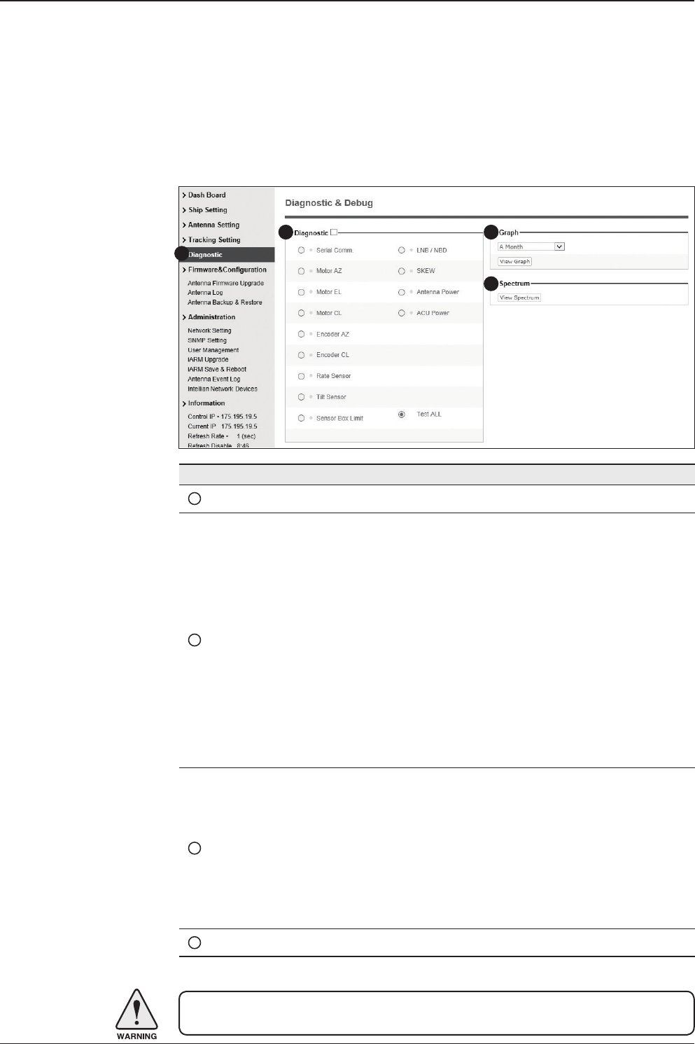
t80W – Marine Satellite TV Antenna System
120
Diagnostic
No. Item Description
1Diagnostic Execute antenna diagnostic test.
2Diagnostic
Select to run a full diagnostic test or single diagnostic test.
- Serial Comm.: test the data communication between the
antenna and the ACU.
- Motor AZ: test the azimuth motor.
- Motor EL: test the elevation motor.
- Motor CL: test the cross-level motor.
- Encoder AZ: test the azimuth encoder.
- Encoder CL: test the cross-level encoder.
- Rate Senor: test the rate sensor.
- Tilt Sensor: test the tilt sensor.
- Sensor Box Limit: test the sensor box motor.
- LNB/NBD: test the LNB.
- SKEW: test the LNB pol motor.
- Antenna Power: test the antenna power.
- ACU Power: test the ACU power.
3Graph
Select to view a graph of AZ Absolute, AZ Relative, EL and
Heading data of the antenna.
- A Month: display all data within a month
- A Week: display all data within a week
- A Day: display all data in a day
- Real-time: display data in real time. Press F5 button to refresh.
- Data Num: set the maximum number of graph data set to be displayed.
- View Graph: select to view the data graph.
4Spectrum Select to view a current spectrum graph and to set the spectrum.
WARNING: Tick the checkbox before modifying the settings. Click Diagnosis button to
execute diagnostic test. To clear previous diagnosis result, click Diagnosis Clear button.
1
2 3
4
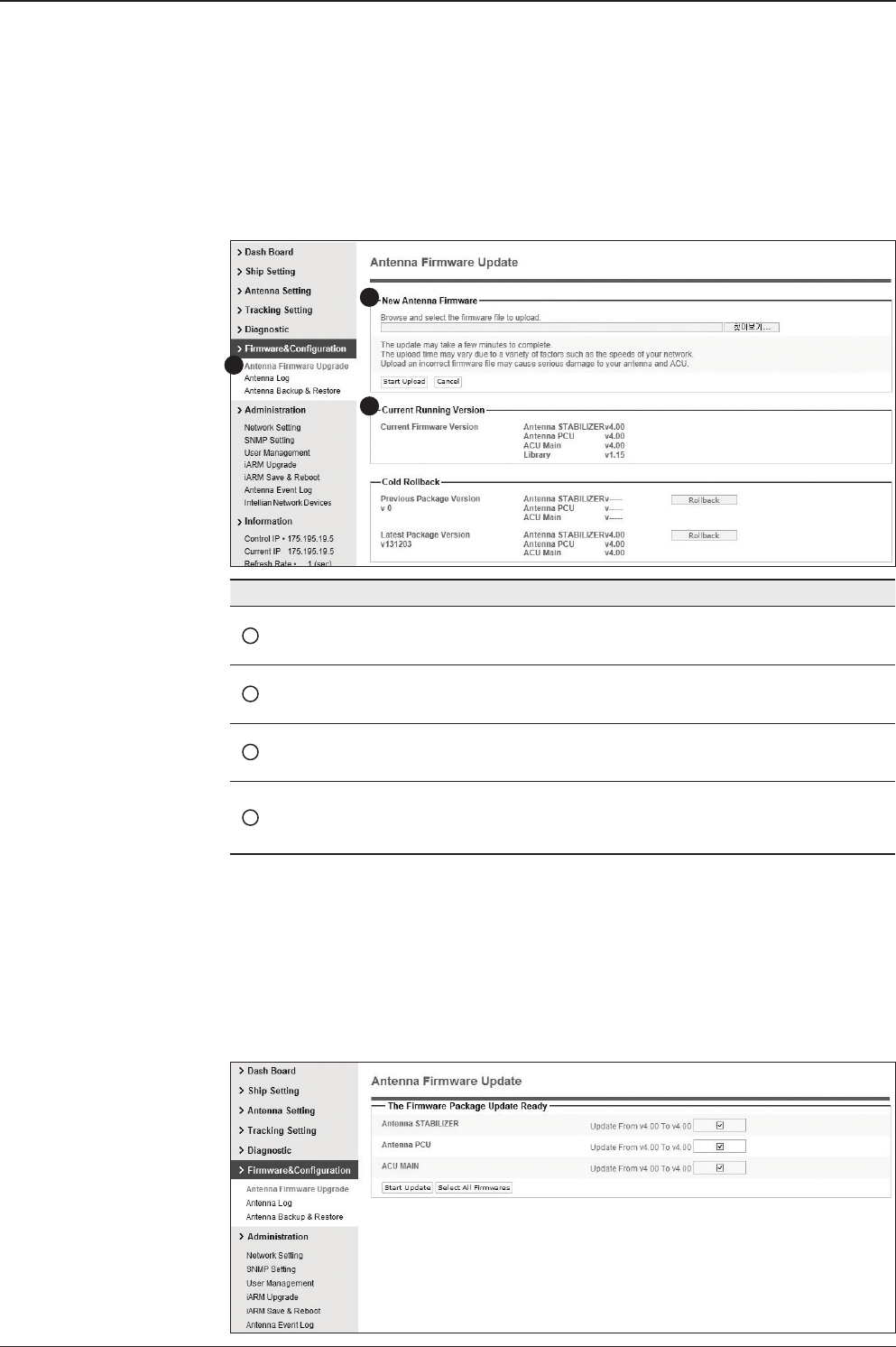
121
APTUS WEB
Antenna Firmware Upgrade
Firmware & Conguration
No. Item Description
1Antenna Firmware
Upgrade Upgrade antenna and ACU rmware version.
2New Antenna
Firmware
Browse and select the rmware package le to upload and
click Start Upload button.
3Current Running
Version
Display current rmware version (Antenna STABILIZER,
Antenna PCU, ACU main, Library)
4Cold Rollback
Display Previous/Latest Package version and rollback
rmware to Previous or Latest version (Can do nothing while
rollback is in progress)
Upgrade procedures:
1. Select the upgrade package le.
2. Click on “Start Upload” button to transfer the Firmware package le (“*.fwp”) to
iARM module.
3. After the package le is transferred, it’ll show “upgrade from vx.xx Version to vx.xx
Version”. Enable the check box to select the rmware le that you wish to upgrade.
To select all rmware les, click Select All Firmwares.
4. Click on “Start Upgrade” button.
1
3
2
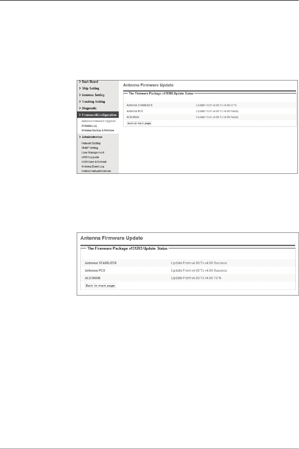
t80W – Marine Satellite TV Antenna System
122
Firmware upgrade
status page
Upgrade process
status page
5. It'll display information about the upgrade process status on full screen.
6. If the rmware is successfully upgraded, it'll display "The rmware update is
completed."
7. Click on "Back to main page" to go out of the screen.
To verify the upgraded rmware version, go to Dash Board > Software Information.
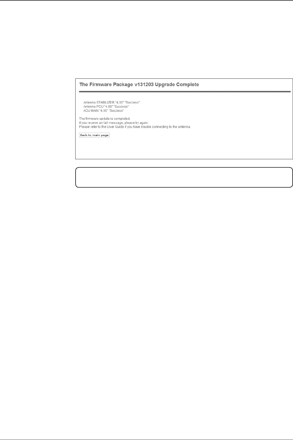
123
APTUS WEB
Upgrade complete
page
NOTE: To roll back to the previous rmware package version or latest package version,
select Rollback Upgrade menu on the Antenna Firmware Upgrade page.
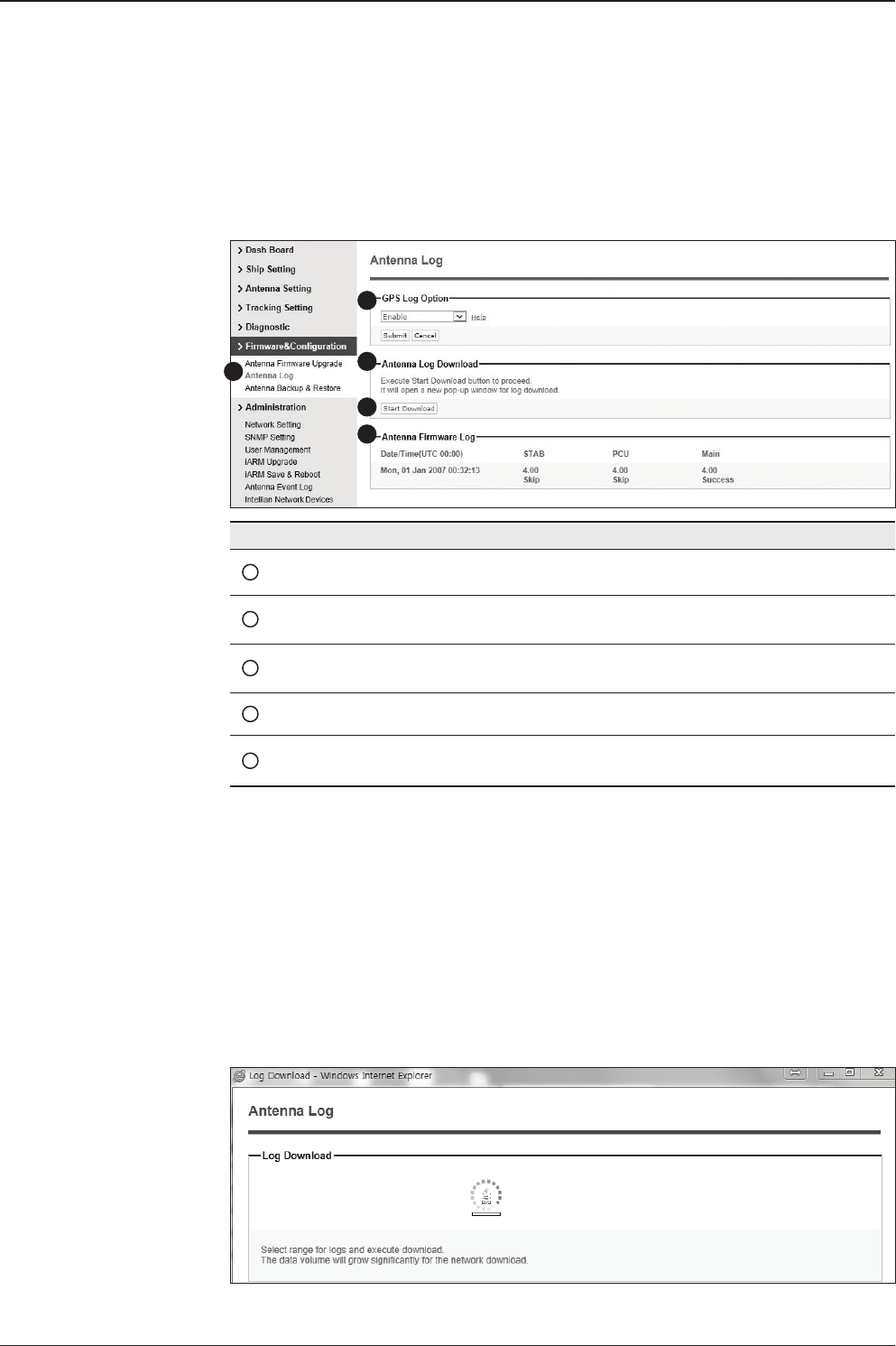
t80W – Marine Satellite TV Antenna System
124
Antenna Log
No. Item Description
1Antenna Log Displays antenna log data
2GPS Log Option Disable/Enable to save GPS information in the antenna log le.
3Antenna Log
Download Download the log le. Select start download button to proceed.
4Start Download Download the antenna log information.
5Antenna
Firmware Log Display log information of rmware upgrade.
Log Downloade procedures:
1. Select ‘Start Download’ button.
2. To run Java applications you must have Java Runtime Environment
JRE) version 6.0 and above installed in your PC/ laptop when you
access the antenna log page for rst time. Click “Run” button on
the popup message “The application’s digital signature cannot be
veried. Do you want to run the application? ” to install the Applet.
Refer to Appendix for Java Installation Instructions if the system
does not display the popup message.
13
4
5
2
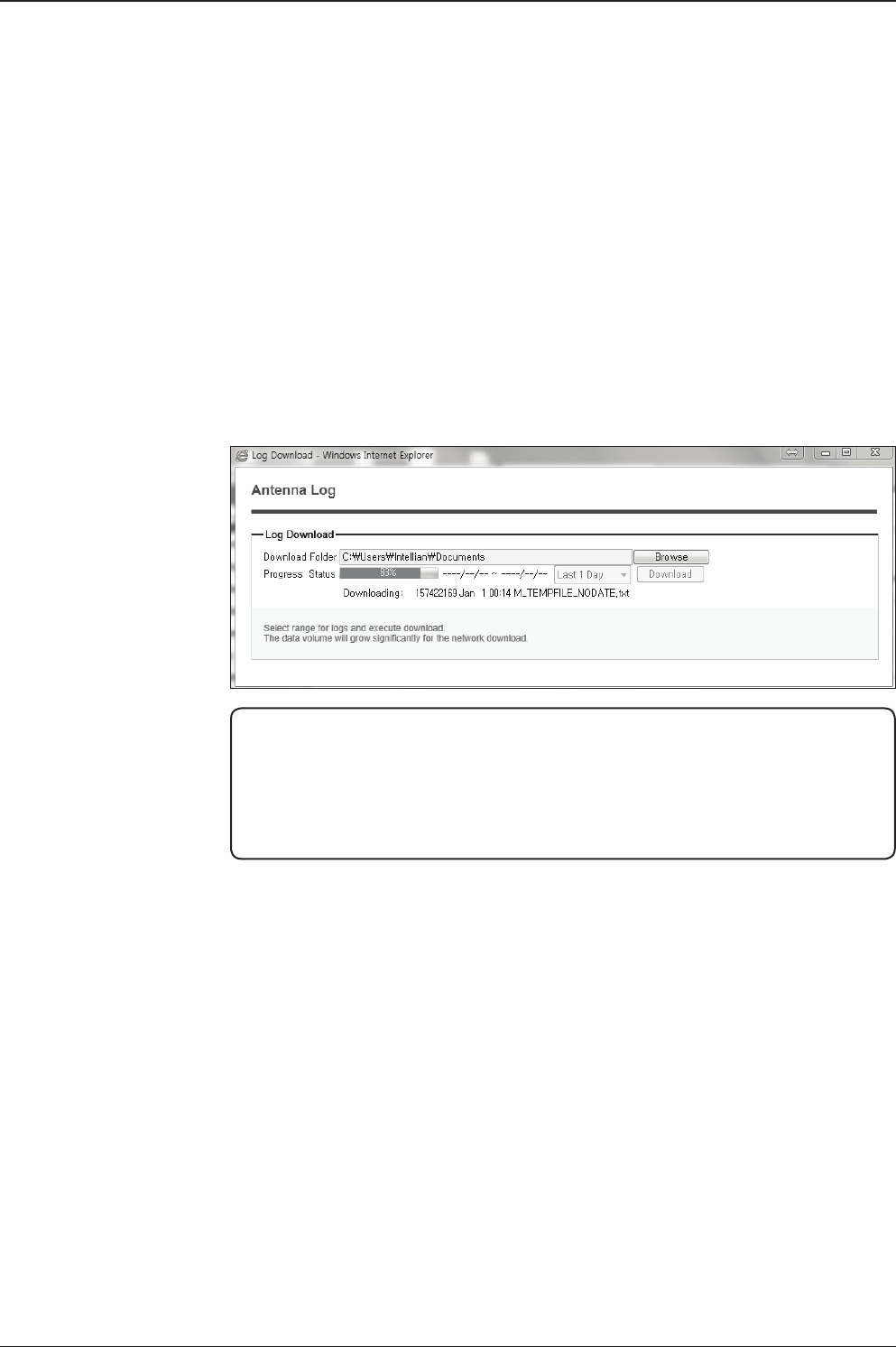
125
APTUS WEB
3. Select ‘Browse’ to browse the target directory of the antenna log le.
4. Select log period for le download.
- Last 3 Months: download the antenna log information for the past three
months.
- Last 1 Month: download the antenna log informaiton for the past one month.
- Last 1 week: download the antenna log information for the past one week.
- Last 1 Day: download the antenna log information for the past one day.
5. Select ‘Download’to download the log le to the target directory according to the
selected log period.
NOTE: In t80W system, users can choose to Enable or Disable the GPS tracking
function. Liability for information that is disclosed when GPS is enabled is solely the
operators responsibility and it is up to the operator on whether or not to provide their
GPS information to third parties. Any issues regarding safety and privacy when turning
on the GPS function is solely up to the user. Intellian is not responsible for information
that is disclosed when the GPS function is enabled.
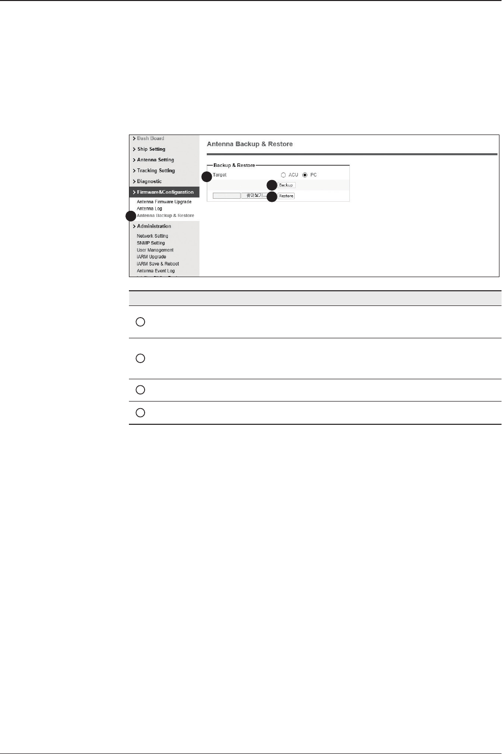
t80W – Marine Satellite TV Antenna System
126
Antenna Backup & Restore
No. Item Description
1Antenna Backup & Restore Enter Backup & Restore page. (Setup mode is
required)
2Target
Backup antenna information to ACU/PC or
restore antenna by using the saved information
from ACU/PC.
3Backup Backup antenna information.
4Restore Restore antenna information.
1
3
4
2
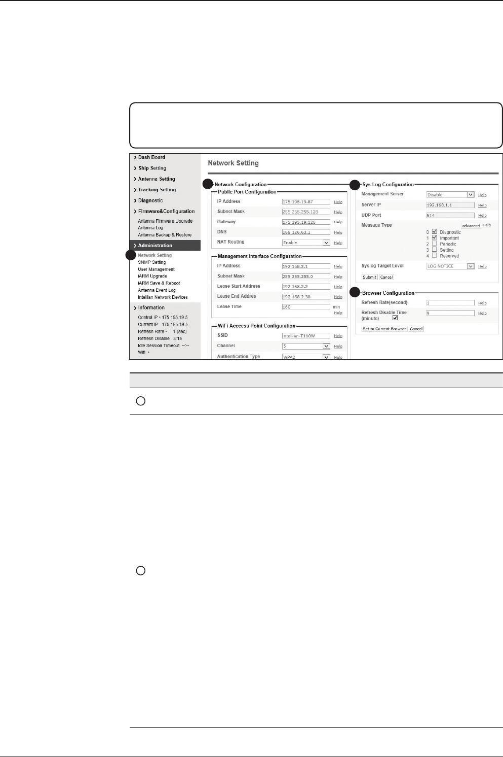
127
APTUS WEB
Administration
No. Item Description
1Networking Setting Enter network setting page.
2Network
Conguration
Modify ACU’s internal IP address and click the Submit
button. Go to the “Save & Reboot” page and click the
Save & Reboot button to validate the changes.
• Public Port Conguration
- IP Address : Factory default (Primary:192.168.0.223)/
(Secondary:10.10.1.1).
- Subnet Mask : Factory default(255.255.255.0).
- Gateway : Factory default(192.168.0.254).
- DNS : Current default DNS Address is assigned to.
- NAT Routing : Enable/Disable NAT routing.
• Management Interface Conguration.
- IP Address : ACU front network port /Factory
default(Primary:192.168.2.1)/(Secondary:10.10.10.1).
- Subnet Mask : Factory default(255.255.255.0).
- Lease Start Address : Lease IP address start range.
- Lease End Address : Lease IP address end range.
- Lease Time : Lease IP address update time.
WARNING: Ensure to enter the SETUP mode before starting conguration. After
completing the modication of settings, enter Save & Reboot page and click on “Save &
Reboot” button. Without doing so, the modied settings will be lost.
1
23
4

t80W – Marine Satellite TV Antenna System
128
• Wi-Fi Access Point Conguration.
- SSID : The SSID is the network name shared among
all devices in a wireless network. The SSID must be
identical for all devices in the wireless network. It is case-
sensitive and must not exceed 32 alphanumeric charac-
ters, which may be any keyboard character. Make sure
this setting is the same for all devices in your wireless
network.
- Channel : Select an appropriate channel from the list
provided to correspond with your network settings. All
devices in your wireless network must use the same
channel in order to function correctly. Try to avoid con-
icts with other wireless networks by choosing a channel
where the upper and lower three channels are not in use.
- Authentication Type : Module supports an authentication
mode that the 802.11 device uses when it authenticates
and associates with an access point or IBSS cell.
- Password : Wi-Fi access password.
- Max Stations : Setting max stations.
• Network Service Conguration.
- Telnet Service : Enable or disable telnet login support.
- HTTPS Port : HTTPS port number.
3Sys Log Conguration
Set the Syslog Conguration.
Antenna makes log messages according to emergency
level. When this function is enabled, your management
server receives the log messages.
• Management Server : Syslog function enable/disable.
• Server IP : Management server IP address.
• UDP Port : Management port.
• Message Type : Select message type(Intellian message
level) to send management server (The lower level is
more emergency).
• Syslog Target Level : If you select this target level, the
Server receives log message equal or less than this level.

129
APTUS WEB
4Browser
Conguration
Set the refresh rate and the refresh disable time.
• Refresh Rate : Set the browser refresh rate (Default 1
seconds. Range 1~99).
• Refresh Disable Time : Set the browser idle
timeout(Default:9 minutes. Range 0~9).
If you tick the checkbox, you can use this function.
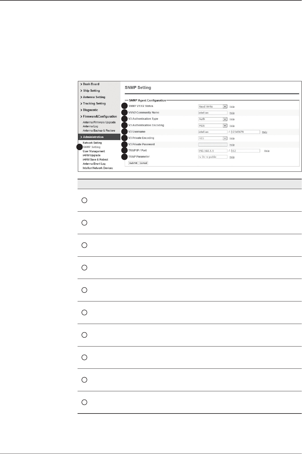
t80W – Marine Satellite TV Antenna System
130
SNMP Setting
No. Item Description
1SNMP Setting Display and Set SNMP conguration.
2SNMP V1/V2 Status Set SNMP mode(Use Attribution Disable, Read Only
or Read Write).
3V1/V2 Community Name Set SNMP V2 community name.
4V3 Authentication Type Set SNMP V3 authentication mode.
5V3 Authentication Encoding Set SNMP V3 authentication encoding.
6V3 Username Set the V3 username and password of the SNMP
Agent. The password is at least 8 character string.
7V3 Private Encoding Set SNMP V3 Private Encoding.
8V3 Private Password Set the V3 password of the SNMP Agent. The
Password is at least character string.
9TRAP IP/Port Set the V3 password of the SNMP Agent. The
Password is at least character string.
10 TRAP Parameter Set the SNMP trap specic parameter.
1
3
4
5
6
7
8
9
10
2

131
APTUS WEB
User Management
No. Item Description
1User
Management
Change login ID and Password to access the Web M&C. This set-
ting can be also accessed by ‘Account’ icon on the top menu.
2Change
ID & Password
Change your login ID (username) and password.
• Change ID : Enter your current login ID (username) and new
login ID. Click the Submit button to validate the changes that are
made to the login ID.
• Change Password : Enter your current login password and new
login password. Click the Submit button to validate the changes
that are made to the login password.
3Change
User Settings
Change User Password Expire in days and Idle session timeout.
• Password Expire Timeout : Set password expire in days.
• Idle Session Timeout : Set for Console and for Network Timeout.
1
3
2
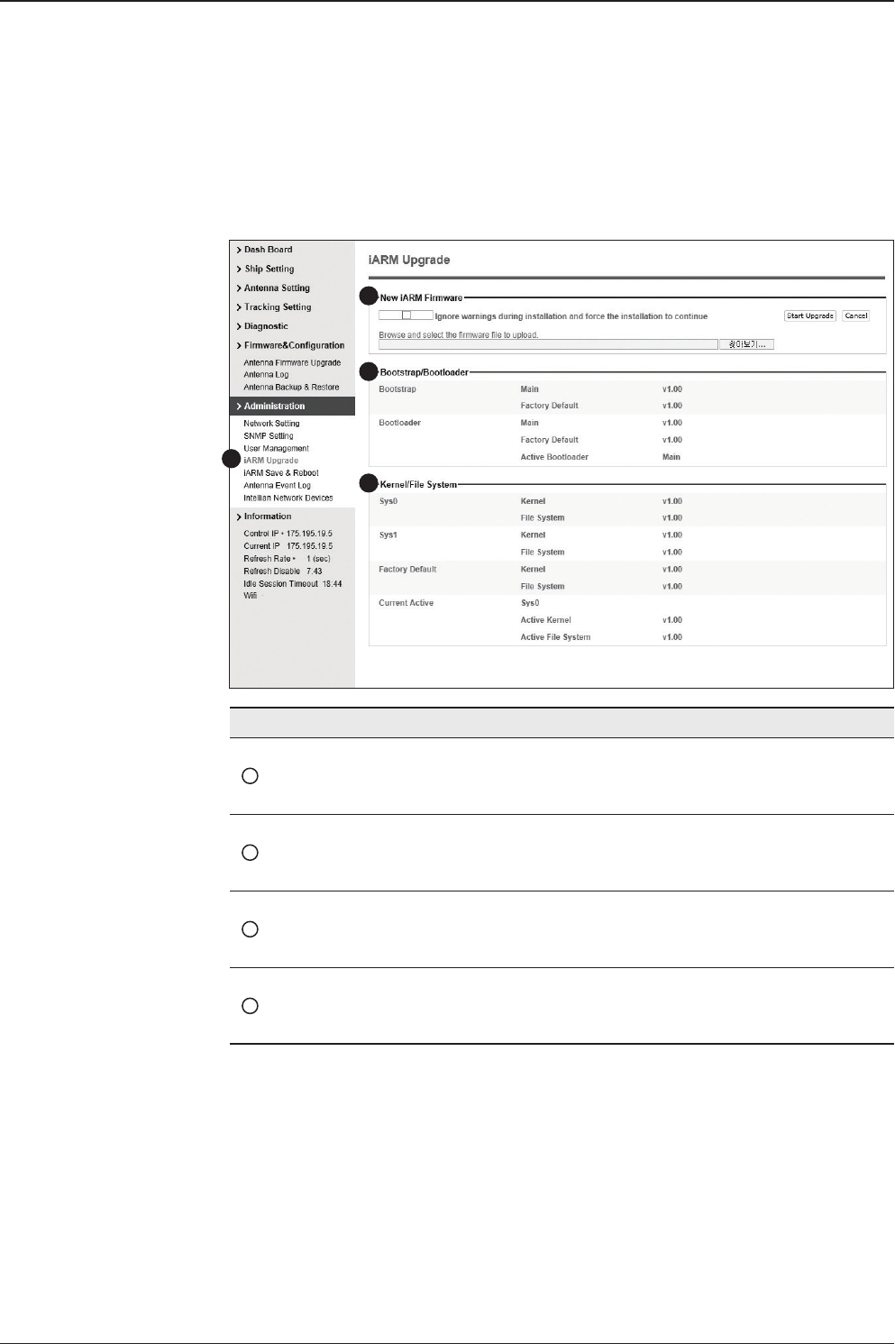
t80W – Marine Satellite TV Antenna System
132
iARM Upgrade
No. Item Description
1iARM Upgrade Upgrade the rmware of iARM module.
2New iARM
Firmware
Select a new rmware le and click Start Update button to
upgrade the rmware.
3Bootstrap
/Bootloader Displays current bootstrap and bootloader version.
4Kernel
/File System
ACU has 3 storage parts sys0, sys1, Factory Default
Display kernel and le system version and current activated
part Information.
iARM rmware upgrade procedures:
1. Click on “Browse” button to select the iARM rmware le (.tgz) that you
wish to upgrade.
2. Click on “Start Update” button to update the iARM rmware. Wait until
the page is loaded.
3. It’ll inform you that the rmware is being uploaded.
1
3
4
2
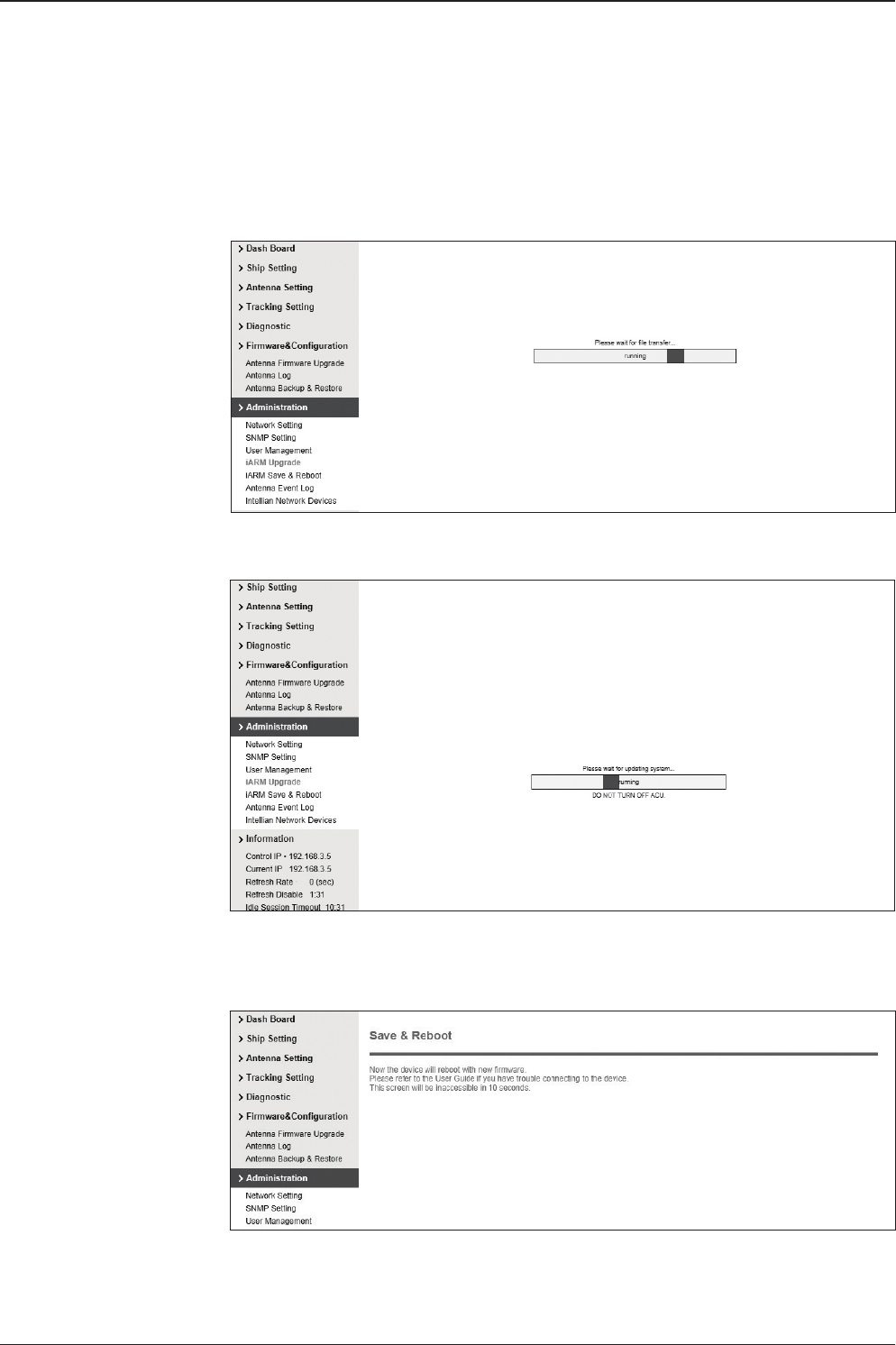
133
APTUS WEB
4. Do not turn off the ACU power if the rmware upgrade page is displayed.
5. It’ll take around 2 minutes to complete the rmware upgrade. Once the upgrade
is completed, the system will reboot automatically.
Firmware upload in
progress
Firmware upgrade in
progress
6. The connection will be disconnected during the reboot. It’ll take around
30 seconds to reboot the iARM module and get the connection back
again. (Disconnection message may vary depending on the web browsers.)
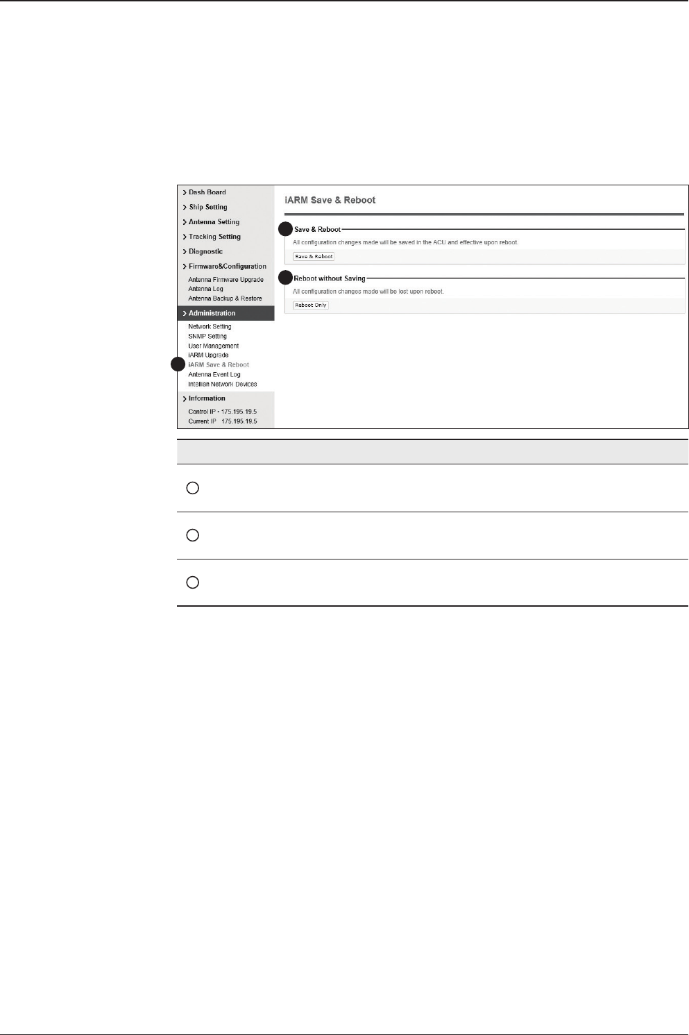
t80W – Marine Satellite TV Antenna System
134
iARM Save & Reboot
No. Item Description
1iARM
Save & Reboot
Save settings to the ACU and reboot or reboot the system
without saving.
2Save & Reboot Save the modied settings and reboot the system.
Click Save & Reboot button.
3Reboot without
Saving
Reboot the system without saving the modied settings.
Click Reboot Only button.
1
3
2
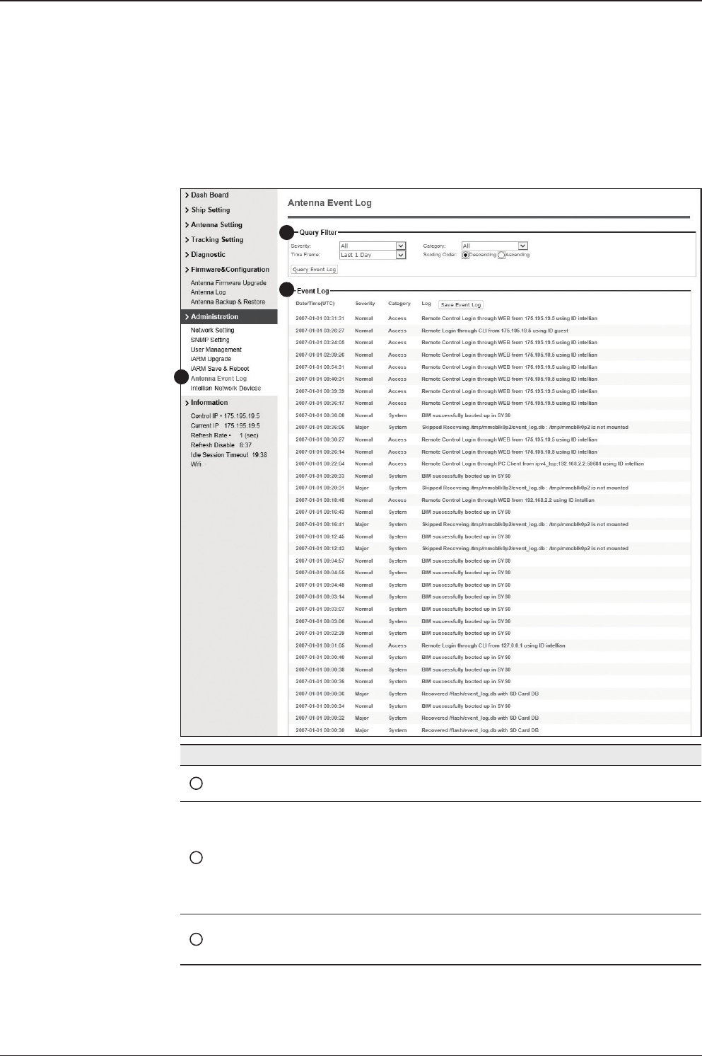
135
APTUS WEB
Antenna Event Log
No. Item Description
1Antenna
Event Log Displays user's log information (Data/Time, Login ID and IP)
2Query Filter
Set the Log message option.
• Severity : Set urgency level.
• Category : Set target that caused the message.
• Time Frame : Set time limit that you want to show.
• Sorting Order : Sorting based on date(descending or as-
cending).
3Event Log Displays log information (Date/Time, Severity, Category, Log).
• Save Event Log : Save log message to your PC
1
2
3
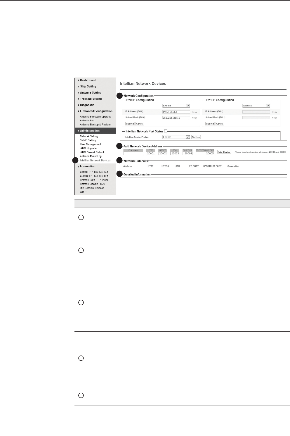
t80W – Marine Satellite TV Antenna System
136
Intellian Network Devices
1
3
4
5
2
No. Item Description
1Intellian Network
Devices
Add up to 8 network devices and enable to monitor real time
information of the connected device.
2Network
Conguration
• Eth0 IP Conguration : ACU network Eth0 IP and subnet
mask setting.
• Eth1 IP Conguration : ACU network Eth1 IP and subnet
mask setting.
• Intellian Network Port Status : not used on t-series.
3Add Network Device
Address
Add Intellian network devices, then you can browse the
various information of the device.
• IP Address : IP address of the device to be monitored.
• HTTP, HTTPS, SSH : Set port number(These port
numbers will be matched the http, https or SSH port
number of each device).
4Network Data View
Displays the setting information of the added device
(IP address, http, https, SSH port number, current
connection).
If you click the http/https port number of each device,
then you can connect to the device’s web page.
If you click Delete Device button, then you can’t see its
information.
5Detailed Information Displays the information of each device. (Updated every 3
second).

137
Technical Specication
Technical Specication
General
Approvals
CE – conforms to EU Directive 89/336/EEC
FCC – veried to CFR47: Part 15
Dimensions
Satellite antenna unit 113cm x 121cm (44.6" x 47.5")
Antenna dish diameter 85cm (33.5")
Antenna control unit 43.1cm x 38cm x 4.4cm (17" x 15" x 1.7")
Weight
Satellite antenna unit 82.2 kg (181.2 lbs)
Antenna control unit 3.5kg (7.7lbs)
Environmental
Operating temp. range -25°C to +55°C (-13°F to +131°F)
Storage temp. range -40°C to + 80°C (-40°F to + 176°F)
Humidity limit 95% R.H
Power requirements 110/220V AC
Power consumption Typ. 50W, Max. 100W
Antenna System Performance
Frequency Ku-band(10.7 to 12.75 GHz)
Minimum EIRP 44 dBW
Azimuth range 680°
Elevation range -15° ~ +110°
Cross-level range ±30°
Roll / Pitch / Yaw ±25° / ±15° / ±8° @ 6 sec period
Turn rate Up to 12° / sec and 15° / sec2

t80W – Marine Satellite TV Antenna System
138
Warranty
This product is warranted by Intellian Technologies Inc., to be free from defects in
materials and workmanship for a period of Three (3) YEARS on parts and ONE (1)
YEAR on labor performed at Intellian Technologies, Inc. service center from the
purchased date of the product.
Intellian Technologies, Inc. warranty does not apply to product that has been
damaged and subjected to accident, abuse, mis-use, non-authorized modication,
incorrect and/ or non-authorized service, or to a product on which the serial number
has been altered, mutilated or removed.
It is required to present a copy of the purchase receipt that indicates the date
of purchase for after-sales service under the warranty period. In case of failure
to present the purchase receipt, the warranty period will begin 30 days after the
manufacturing production date of the product purchased.
Any product which is proven to be defective in materials or workmanship, Intellian
Technologies, Inc. will (at its sole option) repair or replace during the warranty
period in accordance with this warranty. All products returned to Intellian
Technologies, Inc. under the warranty period must be accompanied by a return
material authorization (RMA) number issued by the dealer/distributor from Intellian
Technologies, Inc. and a copy of the purchase receipt as a proof of purchased
date, prior to shipment. Alternatively, you may bring the product to an authorized
Intellian Technologies, Inc. dealer/distributor for repair.
