V130G Manual
2017-12-08
: Intellian V130G Manual v130G_Manual v130 d
Open the PDF directly: View PDF ![]() .
.
Page Count: 146 [warning: Documents this large are best viewed by clicking the View PDF Link!]

Marine Satellite Communication Antenna System
v130
Installation and Operation Manual

Serial number of the product
This serial number will be required for the all troubleshooting or service inquiries.
© 2014 Intellian Technologies Inc. All rights reserved. Intellian and the Intellian
logo are trademarks of Intellian Technologies, Inc., registered in the U.S. and other
countries. The v-Series and the v130 are trademarks of Intellian Technologies,
Inc. Intellian may have patents, patent applications, trademarks, copyrights, or
other intellectual property rights covering the subject matter in this document.
Except as expressly provided in any written license agreement from Intellian,
the furnishing of this document does not give you any license to these patents,
trademarks, copyrights, or other intellectual property.
All other logos, trademarks, and registered trademarks are the property of their
respective owners. Information in this document is subject to change without
notice.
Every effort has been made to ensure that the information in this manual is
accurate. Intellian is not responsible for printing or clerical errors.
Doc. No. 2014PQ-UM0325-V1_2

INDEX

5
INDEX
CERTIFICATIONS 6
INTRODUCTION 8
Introduction to the Intellian v130 9
Features of the Intellian v130 10
System Conguration 11
INSTALLING THE ANTENNA 13
System Package 14
Planning the Installation 18
Antenna Installation 22
INSTALLING THE ACU 32
Mounting the ACU 32
Ship Gyrocompass Connection 35
PC to ACU Communication Setup 39
Wi-Fi Connection 41
OPERATING THE ACU 44
Introduction 45
Normal Mode 46
Setup Mode 50
Installation Settings 51
Antenna Settings 54
Satellite Settings 65
System Settings 72
ANTENNA CONTROL SOFTWARE 80
Introduction tp Aptus®81
Software Installation 82
PC to ACU Communication Setup 83
Toolbar Menus 86
System Property Status Dashboard 89
Work View Tabs 93
APTUS WEB 109
Introduction 110
Main Page 111
Antenna Settings 115
Firmware & Conguration 123
Administration 130
WARRANTY 139
APPENDIX 140
TECHNICAL SPECIFICATION 144
ENVIRONMENTAL SPECIFICATION 145
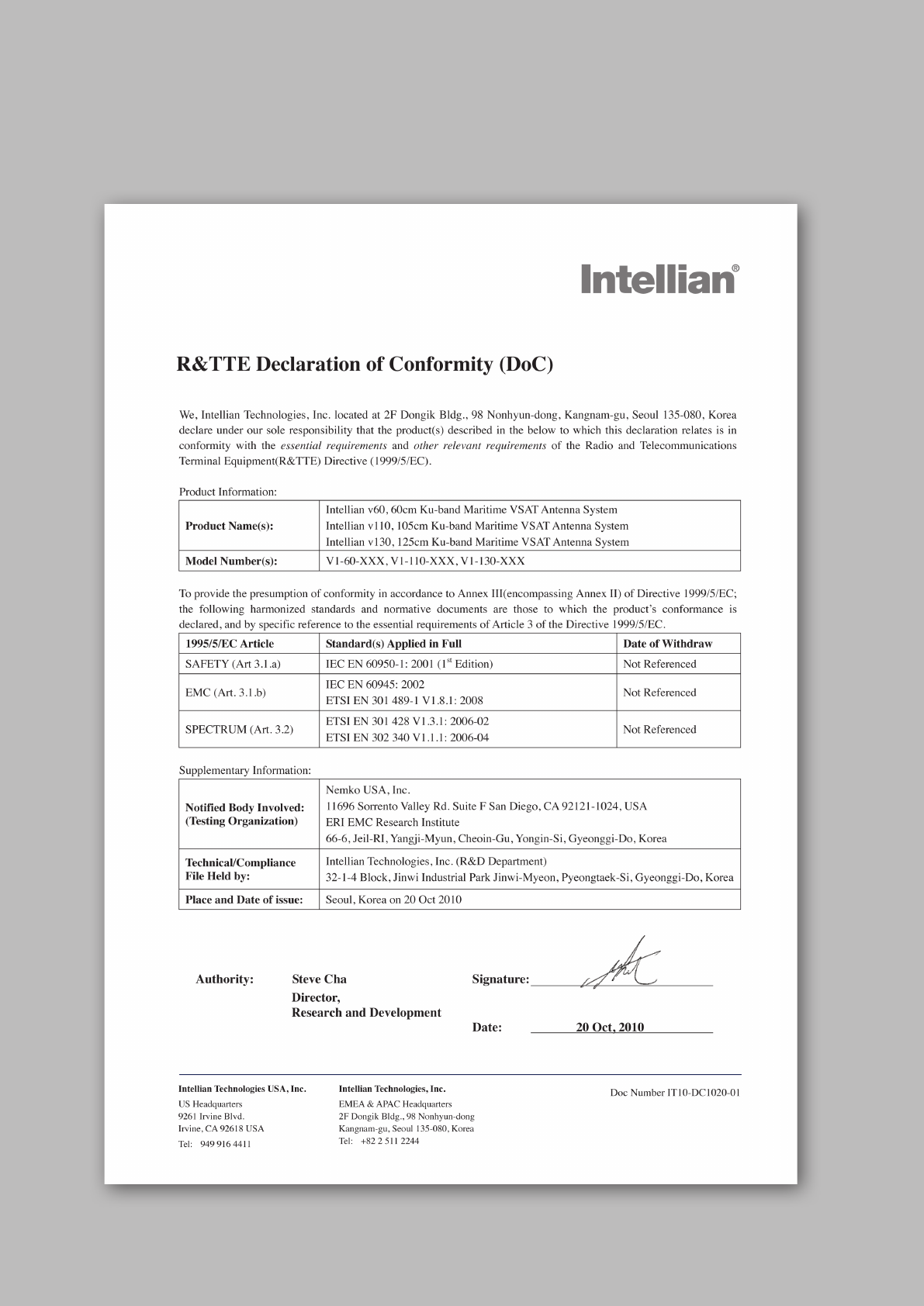
CERTIFICATIONS
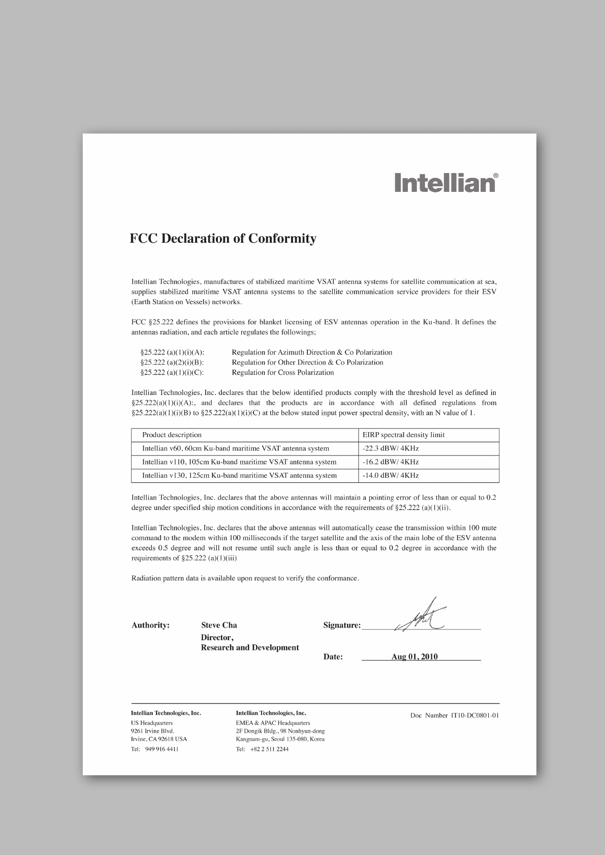

v130 – Marine Satellite Communication System
8
Introduction to the Intellian v130
Features of the Intellian v130
System Conguration
INTRODUCTION

9
INTRODUCTION
Introduction to Intellian v130
Intellian v130 (1.25m) is a ku-band VSAT maritime antenna system that supports
SCPC, TDMA, Spread Spectrum or Carrier-in-Carrier and is suitable for high-speed
internet, email, le transfer, video conference, VoIP, VPNs and database backup.
With its 3-axis stabilized platform and advanced shock-resistant and vibration
damping design, the v130 is capable of withstanding the most demanding sea
conditions to provide “always on” and “high-quality” broadband communications
on all types of vessels.
The v130 is built to meet or exceed the industry’s most stringent standards such as
FCC, ETSI, R&TT, and MIL-STD-167. The v130 offers superior RF performance with
its simple yet sophisticated design that reduces installation time and total cost of
ownership. Equipped with Remote IP access function, the v130 can be accessed,
monitored and controlled from anywhere and anytime to ensure cost-effective
technical supports without having an engineer come on board.
The v130 is fully integrated with ABS (Automatic Beam Switching) function with
leading service providers who use the embedded OpenAMIP protocol of the iDirect
platform and v130 is also compatible with various platforms such as Hughes,
Comtech, SatLink and more. The v130 is available in both cross-pol and co-pol
feeds and supports multi-band LNBs and the option of 4W-25W BUC.

v130 – Marine Satellite Communication System
10
Features of Intellian v130
Enjoy always-on broadband connection at sea
Intellian v130 is the most modern communication system that offers a high-
speed and always-on broadband connection at sea, where the atmospheric and
environmental conditions are very harsh.
Best solution for all kinds of vessels
The v130 is the best solution for all kinds of vessels that require the satellite
broadband connection around the globe. The major RF components are designed
and manufactured by Intellian’s solid in-house engineering to achieve superior
antenna gain and xpol isolation recognized among the best performances in the
industry.
Gyro-free satellite search capability
Intellian’s new generation gyro-free satellite search function enables the v130 to
acquire and lock onto the satellite without requiring a separate input from the ship’s
gyrocompass
Wide elevation range
The v130 have a wide elevation range from -15° to 120° and -20° to 120°,
respectively which offer seamless signal reception while the vessel is traveling near
the Equator or Polar Regions.
Dedicated Management Ethernet Port
The Management Ethernet Port on the front of the ACU enables direct and simple
network connection between a PC and the ACU. The Management Port supports
DHCP network connection by default, allowing automatic IP conguration and
quick access to Intellian's remote management solution, the Aptus Web software.
Wireless Connectivity and Aptus Mobile
The built-in Wi-Fi enables the ACU to be wirelessly connected and can be turned
on or off. Any kind of wireless devices such as PCs, laptops and smartphones can
be used to connect to the ACU and monitor, control and change the settings of the
system wirelessly. An Intellian Aptus Mobile App is available for download to access
to the ACU via Wi-Fi and operate the antenna from iPhone, iPad or other network
devices.
Intellian Network Device Monitoring
Connection between the Intellian LAN port on the ACU to other Intellian antenna
systems enables real time monitoring and control of the connected systems from
the v130. This function provides an integrated control of multiple devices by a single
log-in to the Intellian Aptus Web software.
11
INTRODUCTION
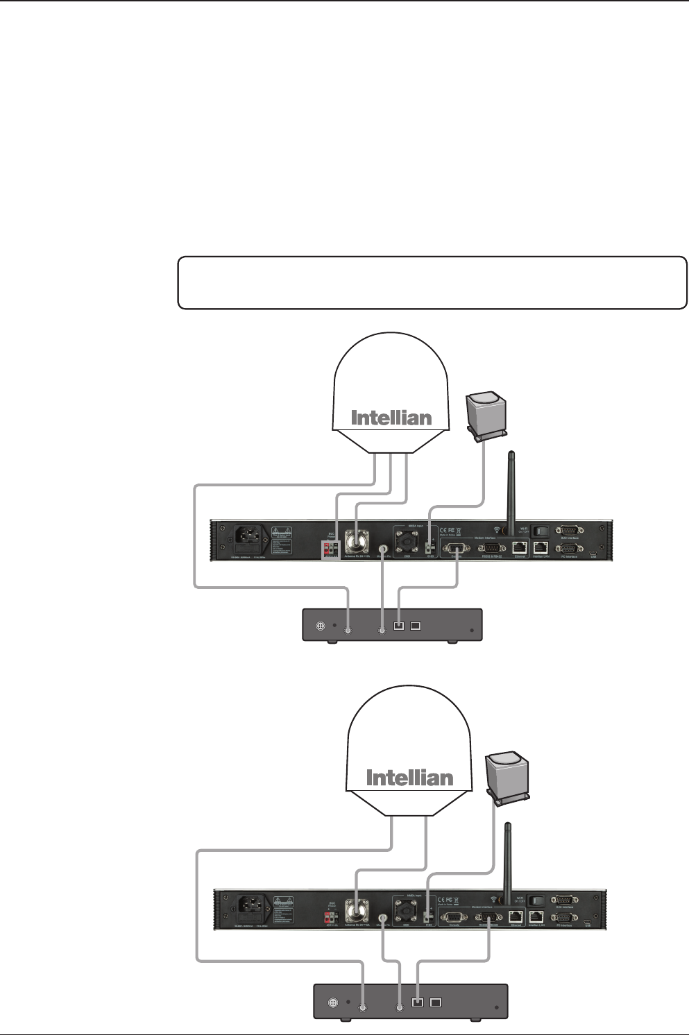
System Conguration
For your satellite communication system to work properly, the system will have to
be connected with all of the provided components properly, as shown in the gure
below. Separate purchase of a satellite modem, ship’s gyrocompass, and Intellian
Dual VSAT Mediator are required.
Basic System
Conguration
(8W BUC)
Basic System
Conguration
(4W BUC)
Satellite Modem
(Not supplied)
Antenna Control Unit
Modem InterfaceModem RX
Antenna TX Antenna RX
BUC
Power
AC 100 ~ 240 V
(50~60 Hz 4A)
Ship’s Gyrocompass
(Not supplied)
PC Interface Tx
ANT1RS232 USB ANT2 MODEM
Rx
ANT1 ANT2 MODEM
ACU Interface
ACU1RS232 & RS422Console ACU
Modem Interface
Ethernet
NMEA
Heading
+ -
BUC
Power
BUC
Power
RX1 TX1 TX2
Antenna
Unit 1
Antenna
Unit 2
RX2
AC 100 ~ 240V (50~60Hz)
Antenna
Control Unit 1
Satellite Modem
Antenna
Control Unit 2
Mediator
Ship’s
Gyrocompass
TX RX Interface
PC
Satellite Modem
(Not supplied)
Antenna Control Unit
Modem InterfaceModem RX
Antenna TX
Antenna RX
AC 100 ~ 240 V
(50~60 Hz 4A)
Ship’s Gyrocompass
(Not supplied)
PC Interface Tx
ANT1RS232 USB ANT2 MODEM
Rx
ANT1 ANT2 MODEM
ACU Interface
ACU1RS232 & RS422Console ACU
Modem Interface
Ethernet
NMEA
Heading
+ -
BUC
Power
BUC
Power
RX1 TX1 TX2
Antenna
Unit 1
Antenna
Unit 2
RX2
AC 100 ~ 240V (50~60Hz)
Antenna
Control Unit 1
Satellite Modem
Antenna
Control Unit 2
Mediator
Ship’s
Gyrocompass
TX RX Interface
PC
NOTE: BUC power should set to ON from the modem when you connect to a 4W
BUC. BUC power should set to OFF from the modem when you connect to an 8W
BUC.
v130 – Marine Satellite Communication System
12
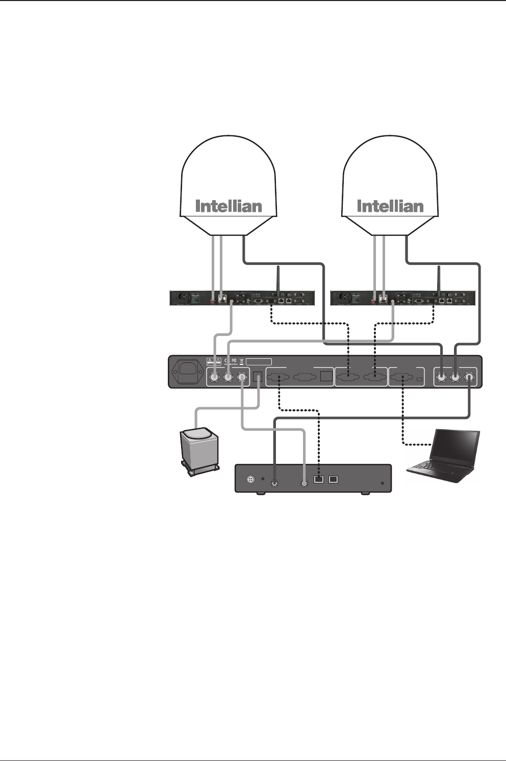
Dual System
Conguration
(8W BUC)
Satellite Modem
(Not supplied)
Antenna Control Unit
Modem InterfaceModem RX
Antenna TX Antenna RX
BUC
Power
AC 100 ~ 240 V
(50~60 Hz 4A)
Ship’s Gyrocompass
(Not supplied)
PC Interface Tx
ANT1RS232 USB ANT2 MODEM
Rx
ANT1 ANT2 MODEM
ACU Interface
ACU1RS232 & RS422Console ACU
Modem Interface
Ethernet
NMEA
Heading
+ -
BUC
Power
BUC
Power
RX1 TX1 TX2
Antenna
Unit 1
Antenna
Unit 2
RX2
AC 100 ~ 240V (50~60Hz)
Antenna
Control Unit 1
Satellite Modem
Antenna
Control Unit 2
Mediator
Ship’s
Gyrocompass
TX RX Interface
PC

13
INTRODUCTION
INSTALLING THE ANTENNA
System Package
Antenna Unit
ACU (Antenna Control Unit)
Installation Kit
Planning the Installation
Selection of Antenna Installation Site
Congure Radiation Hazard/Blockage Zones
System Cables
Power Requirement
Tools Required for Installation
Antenna Installation
Unpacking the Wooden Crate
Antenna Dimensions
Antenna Mounting Templates
Position the Radome
Mount the Radome
RF Cable Connections
Secure the RF Cables

v130 – Marine Satellite Communication System
14
System Package
The package of the Intellian v130 consists of antenna unit, ACU and installation kit
box.
Antenna unit
ACU
Installation kit box

15
INSTALLING THE ANTENNA
Antenna Unit
The antenna unit includes an antenna pedestal inside a radome assembly. The
pedestal consists of a satellite antenna main dish with RF components mounted on
a stabilized pedestal. The radome protects the antenna pedestal assembly from the
marine environment.
Antenna Unit
v130 – Marine Satellite Communication System
16
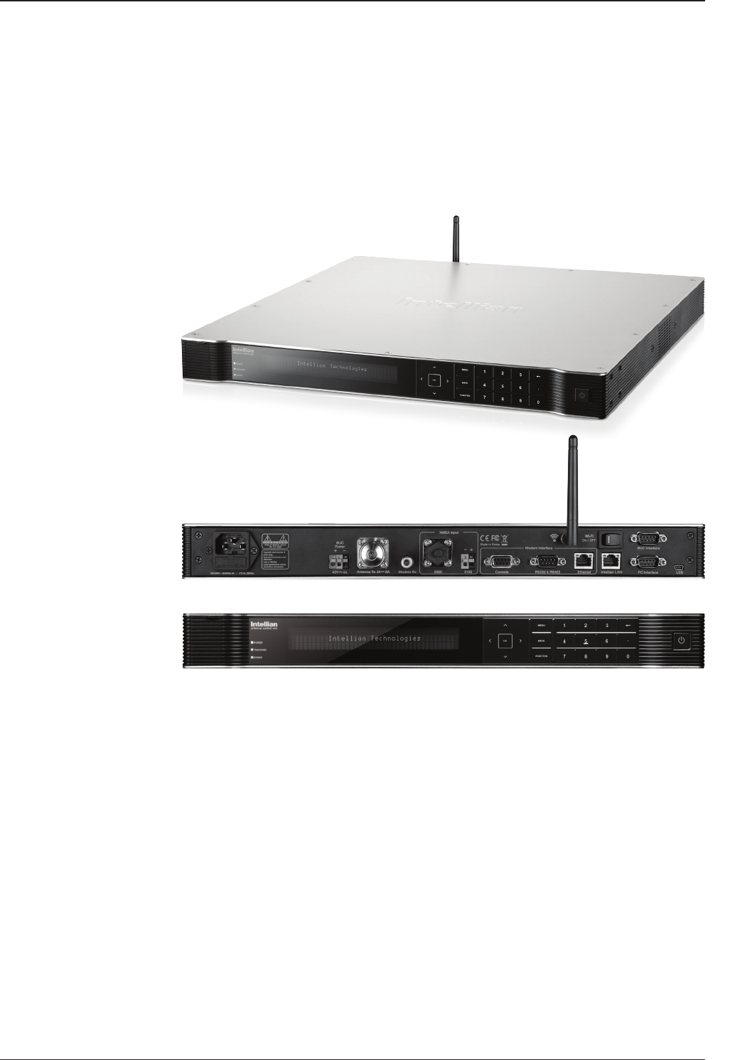
ACU (Antenna Control Unit)
ACU provides power to the antenna and Block Up Converter (BUC), The digital
Vacuum Fluorescent Display (VFD) allows for easy operation of the ACU, even in
the dark.
The functions of the ACU are as follows:
• System startup
• Setting the satellite
• Editing satellite information
• Setting the antenna parameter
• Setting the antenna manual search
• Setting the LNB local frequency
• Setting radiation hazard or blockage zone
• Setting modem connections
• Setting GPS and Gyrocompass
• Display power status
• Performing diagnostic tests
• Backup and restore the system settings
• Set up the interface with a PC
• Supports Wi-Fi ACU operation
• Recording antenna activities and rmware upgrade through USB
• Built-in web-based remote control management
• Front panel Management Ethernet port
Antenna Control Unit
Front panel
Rear panel

17
INSTALLING THE ANTENNA
Installation Kit
Contains the items required for securing the antenna unit and ACU to the vessel.
ACU box
Description Q'ty Size Remarks
Antenna Control Unit (ACU) 1 43.1 x 38 x 4.4cm Antenna Control Unit
User Manual 1
Mounting Tamplate 1
Aptus CD 1
Wi-Fi Antenna 1 110mm
USB Flash Drive 1
Components box
Description Q'ty Size Remarks
ACU Bracket (Rack) 2 ACU-19inch Rack
ACU Bracket (Table) 2 ACU-Table
RG6 Cable 1 3m ACU to Modem
BUC Power Cable 1 15m Antenna to ACU
AC Power Cord (CEE7/7) 1 1.5m ACU Power
AC Power Cord (USA) 1 1.8m ACU Power
PC Serial Cable 1 1.8m ACU to PC
USB Cable (A-A) 1 1.8m ACU to PC
Ethernet Cable (RJ45/LAN) 1 1.5m ACU to PC
iDirect Interface Cable 1 1.5m ACU to modem
D-sub 9 pin Male Connector 2 ACU
N to F Adaptor 1 N(Male) to F(Female) Adaptor
Hex. Bolt 5 M12 x 80L
Antenna mounting 4 Sets,
Spare 1 set
Flat Washer 5 M12
Spring Washer 5 M12
Hex Nut 10 M12
Hex Head Wrench Bolt 5 M6 x 35L
Radome (Spare Bolts)
Spring Washer and Flat Washer 5 M6
Self-Tapping Screw 5 Ø4 x 16 Table Mount Bracket
Flat Head Screw 10 M4 x 12L Rack Mount Bracket ACU
Sems Bolt 5 M3 x 12L Table Mount Bracket ACU

v130 – Marine Satellite Communication System
18
Planning the Installation
Selection of Antenna Installation Site
Install the antenna in accordance with the following procedures to ensure maximum
performance of the antenna. The ideal antenna site has a clear view of the horizon
or satellite all around. Please be sure there are no obstacles within 15º above the
center of the antenna. Any obstacles can prevent the antenna from transmitting and
receiving the satellite signal.
Do not install the antenna near the radar especially on the same plane as the
microwave radar transmissions as these will overload the antenna front-end circuits.
It is recommended to position the antenna at least 4 feet (1.2 m) above or below the
level of the radar and minimum of 15 feet (4.6 m) away from any high power short
wave radars.
The mounting platform should be robust enough and not subject to vibration.
The movement of the antenna can be minimized by installing at the center of the
vessel. If these conditions can be only partially satised, nd the best compromised
installation site between the various considerations.
Elevation Limit
of Obstacles
15°
Congure Radiation Hazard/Blockage Zones
It is important to setup the radiation hazard or blockage zones for Intellian VSAT
communication systems. The ACU can be programmed with relative azimuth and
elevation sectors to create up to ve zones where transmit power could endanger
personnel who are frequently in that area or blockage exists. Several indications are
providedwhen the antenna is within one of these zones.
1. “BLOCK” will be displayed on the ACU screen.
2. Tracking continues as long as the signal level is greater than the predened
threshold value. When the signal level drops below the threshold value the
antenna will wait “Search Wait Time” parameter amount of time and re-target the
satellite last targeted. The antenna will continue to re-target the satellite until the
satellite is re-acquired and tracking can be resumed.
3. A transmit inhibit output from the ACU will disable/mute the modem transmission.
Antenna Unit Obstacle

19
INSTALLING THE ANTENNA
System Cables
Before installing the system cables, you need to take the following points into
consideration.
1. All cables need to be well clamped and protected from physical damage and
exposure to heat and humidity.
2. Cables with an acute bend should be avoided.
3. Where a cable passes through an exposed bulkhead or deck head, a watertight
gland or swan neck tube should be used.
Power Requirement
Intellian v130 has been designed to work on a vessel’s power supply rated at 100-
240 V AC.
• BUC Power Cable
Cable Length mm2 per conductor
Up to 30 meters 1.25 mm2
Up to 50 meters 2.30 mm2
Up to 70 meters 3.00 mm2
Up to 120 meters 5.00 mm2
Recommended
BUC Power Cables
Type Multi-conductor, Shielded
Number of wires 2 conductors for NMEA 0183,
5 conductors for NMEA 2000
• Gyro Compass / GPS Interface Cable (Customer Supplied)
• RF Cable (Customer Supplied)
Due to the signal losses across the length of the RF coax on L-Band, Intellian
recommends the following 50-ohm coax cable types for standard system
installations. For cables that run longer than 150 meters, please consult Intellian
Technologies.
Recommended
RF Cables Coaxial Cable
Type
Attenuation in
dB/100M
Attenuation in
dB/M
Recommended
Cable Length
LMR300 30.3 0.303 35M
LMR400 19.6 0.196 60M
LMR500 15.9 0.159 80M
LMR600 12.8 0.128 100M
LMR900 8.6 0.086 150M
LMR1200 6.5 0.065 200M

v130 – Marine Satellite Communication System
20
Power Drill
Phillips-Head Screwdriver
Flat Head Screwdriver
(min 5mm)
Tools Required for Installation
11 mm Spanner
19 mm Spanner
5 mm Allen/Hex key
21
INSTALLING THE ANTENNA
Antenna Installation
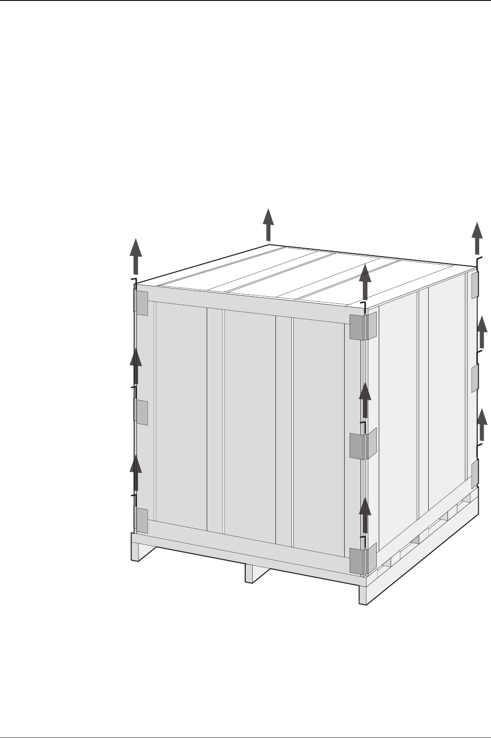
Unpacking the wooden crate of v130
Step 1.
Remove the top panel and 12 pins from the hinges of the wooden crate.
v130 – Marine Satellite Communication System
22
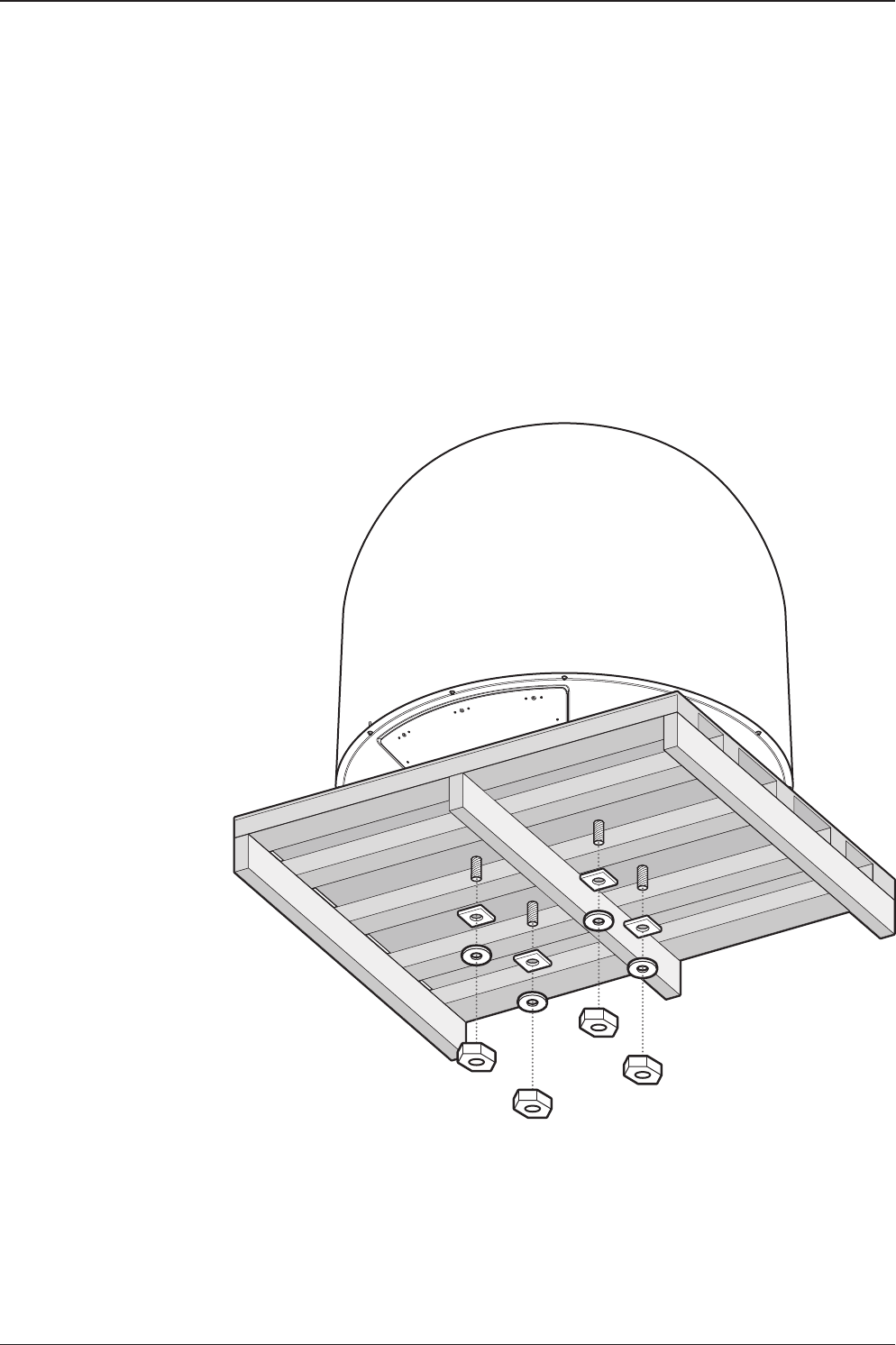
Step 2.
Remove 8 tapping screws that mount the ACU box and installation kit box to the pallet.
23
INSTALLING THE ANTENNA
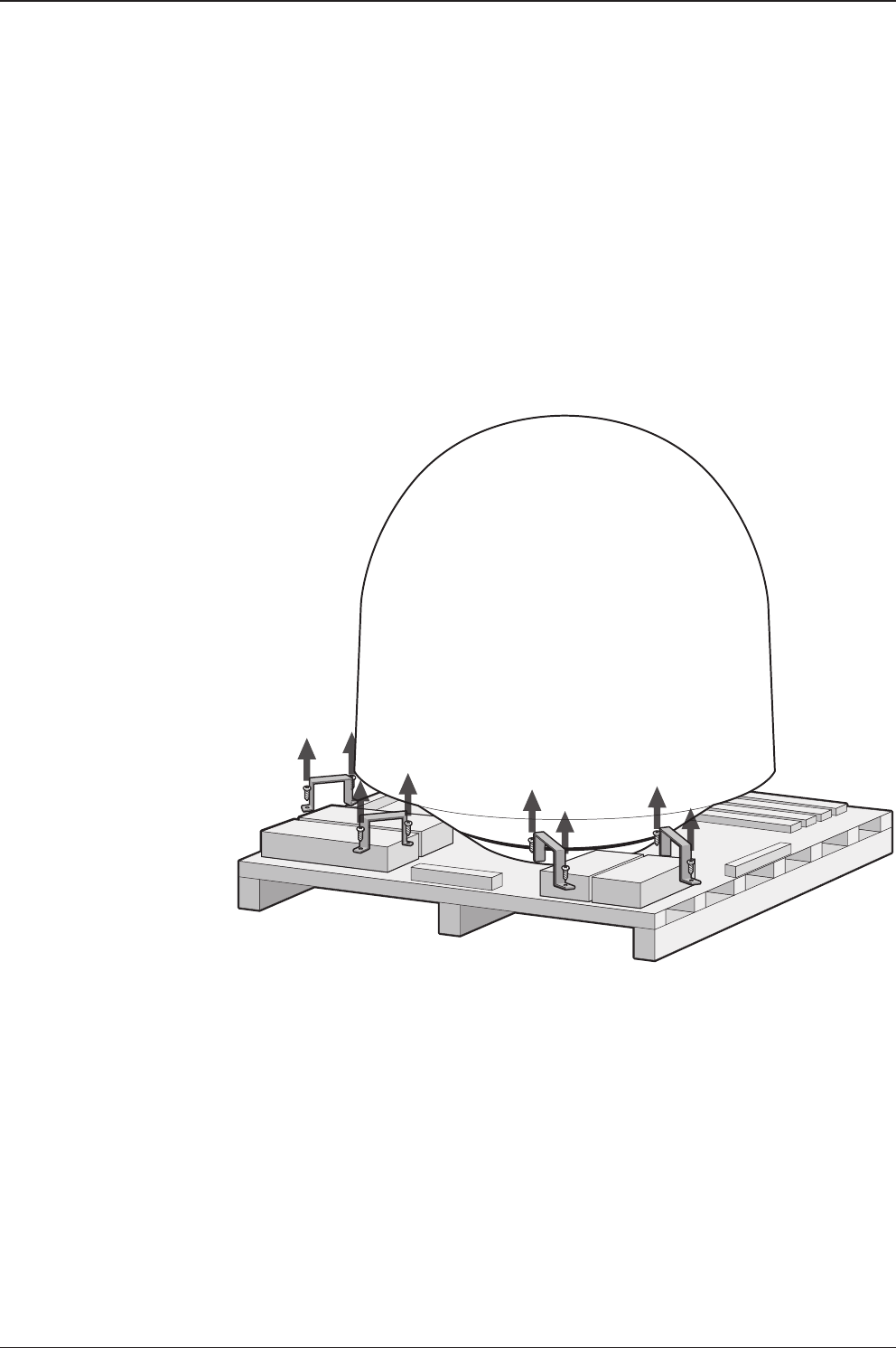
Step 3.
Lift the pallet by using a suitable size of lifting equipment.
Using a 19mm spanner, remove 4 shipping bolts that mount the antenna to the pallet.
v130 – Marine Satellite Communication System
24
Step 5.
Remove the ratchet strap.
* The photo with the opened radome is only for display purpose.
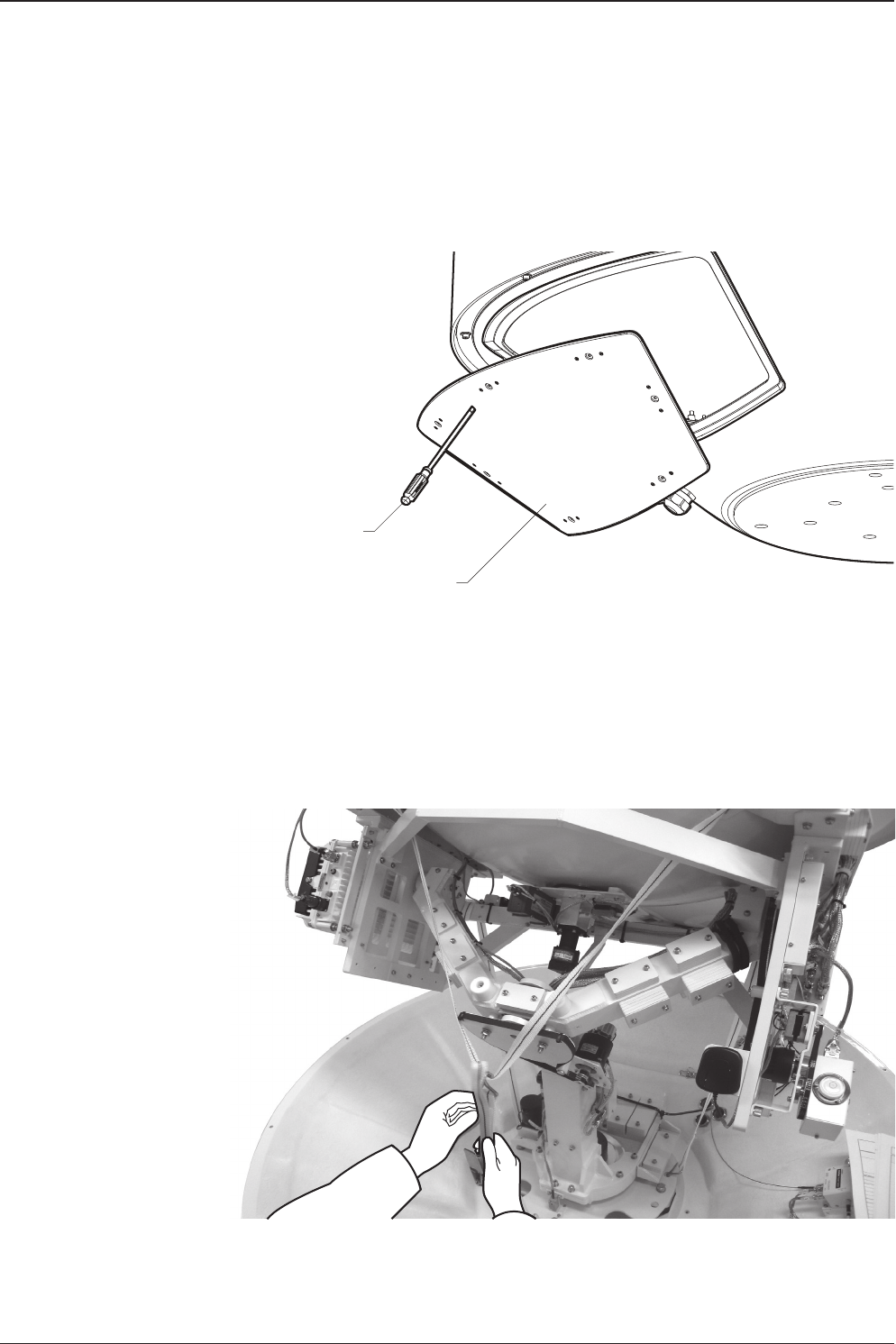
Step 4.
Open the radome hatch.
Radome Hatch
Flat Head Screwdriver
(min 5mm)
25
INSTALLING THE ANTENNA
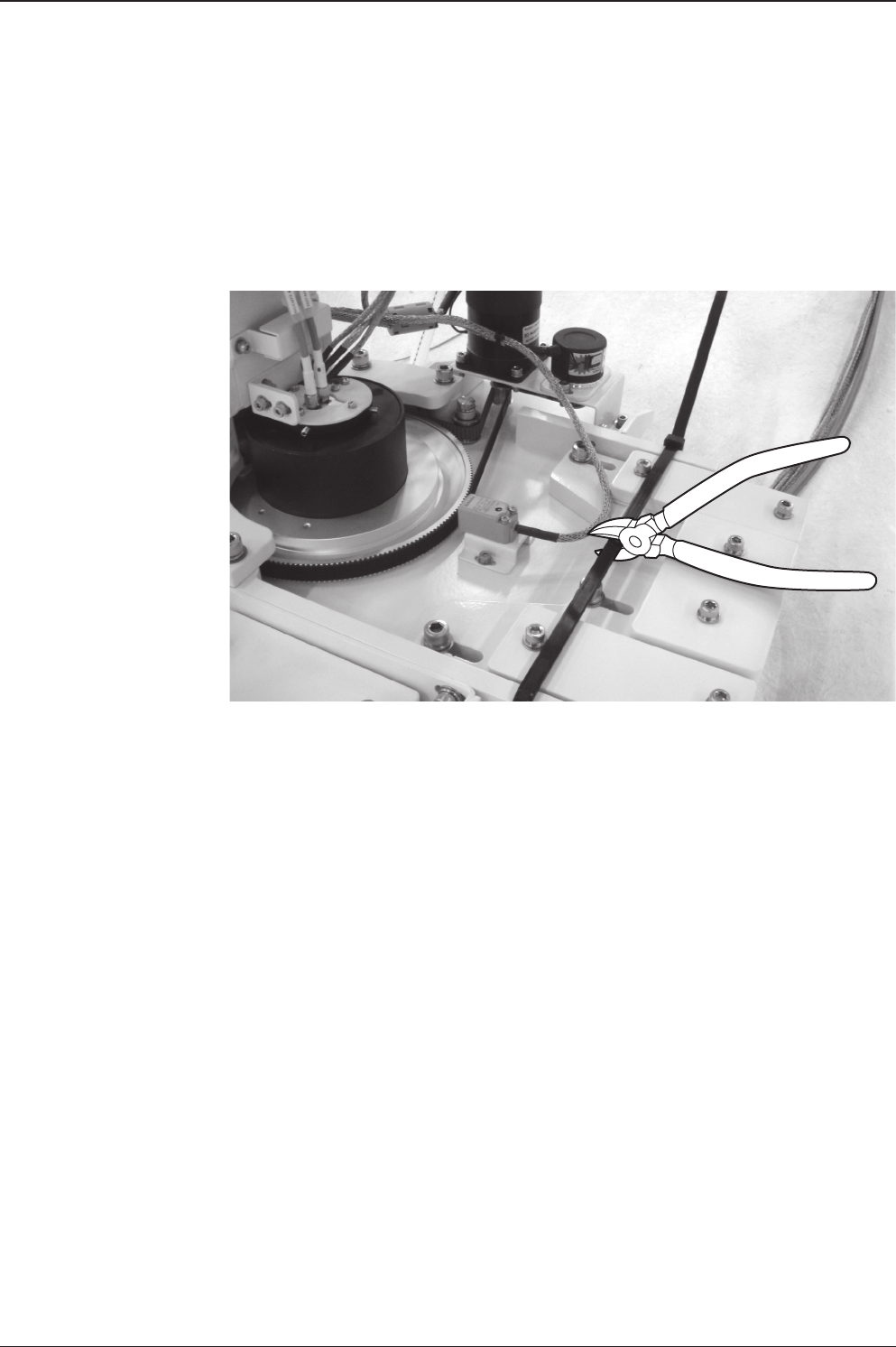
Step 6.
Remove the tie wrap from the pedestal. Do not turn on the antenna power if the shipping
restraints from the antenna pedestal have not been removed completely.

v130 – Marine Satellite Communication System
26
Antenna Dimensions
The method of installation and mounting of antenna may vary with vessel design
but the following procedures are applicable in most situations, and will result in a
secure and effective installation. Conrm the height and diameter of the antenna
before installing it.
147.4 cm (58")
152.2 cm (59.9")
168.9 cm (66.5")
165.2 cm (65")
Radome Dimensions
27
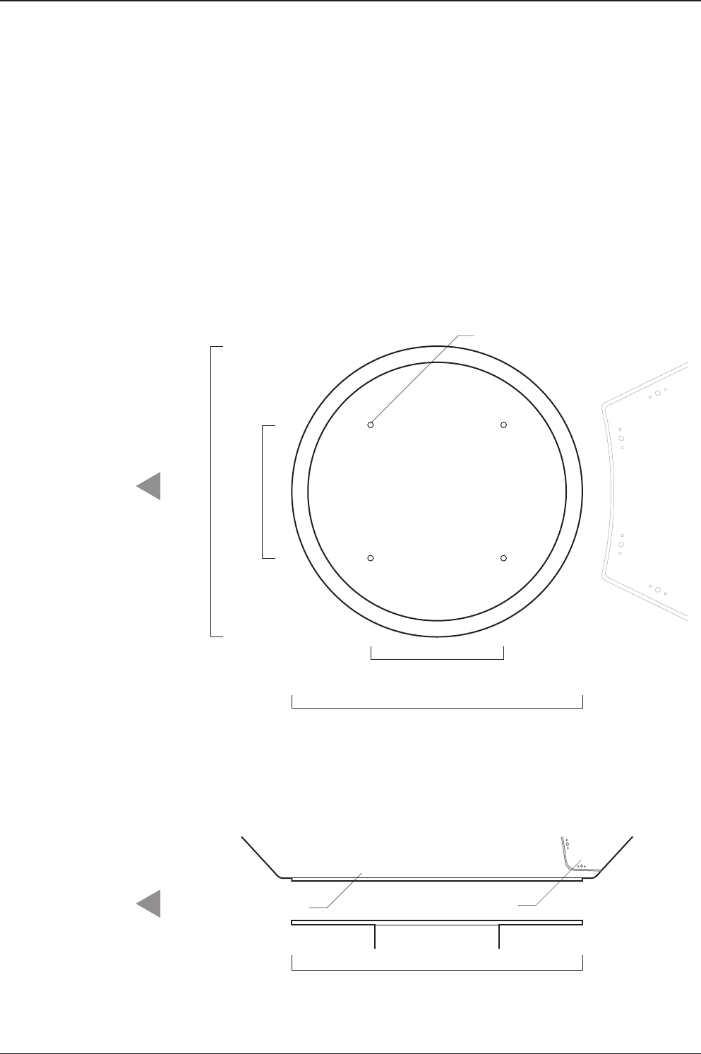
INSTALLING THE ANTENNA
24.75 cm (9.74")
Ø54 cm (21.3")
Ø54 cm (21.3")
Radome Hatch
Radome Bottom
4-Ø13 mm(0.5") Holes
Ø54 cm (21.3")
24.75 cm (9.74")
BOW direction
BOW direction
Antenna Mounting Templates
The mounting holes must be in the exact same place as shown in the diagram
below. The radome should be positioned with the Bow marker aligned as close
as possible to the centerline of the ship. Variation from actual alignment can be
compensated with the "BOW Adjust" settings in the ACU.

v130 – Marine Satellite Communication System
28
Position the Radome
The radome should be positioned with the BOW marker aligned as closely as
possible to the ship’s centerline.
Mim. 120 cm (47”)
Mounting Plate
Min. 1 cm (0.4”)
Max. 3 cm (1.2”)
Support Pedestal
Appr. Ø25.4 cm (10”)
Recommended size of the
support pedestal
29
INSTALLING THE ANTENNA
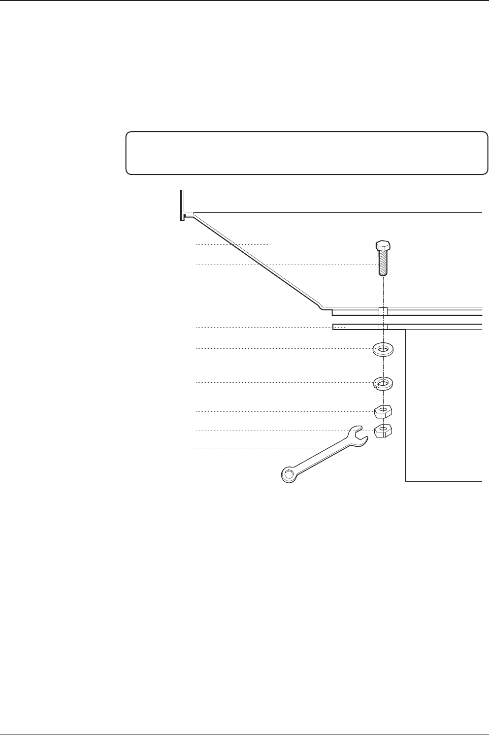
M12 Hex Bolt
Deck
Antenna Unit
M12 Flat Washer
M12 Spring Washer
M12 Hex Nut
M12 Hex Nut
19 mm Spanner
Mounting the Radome
Bolt the radome base directly to the support pedestal.
Note: Ensure to use the Intellian supplied blots from the accessory box when you
mount the radome. Apply Loctite #262 or equivalent to the bolt thread, and fasten it
with the tight torque of 110 N·m
v130 – Marine Satellite Communication System
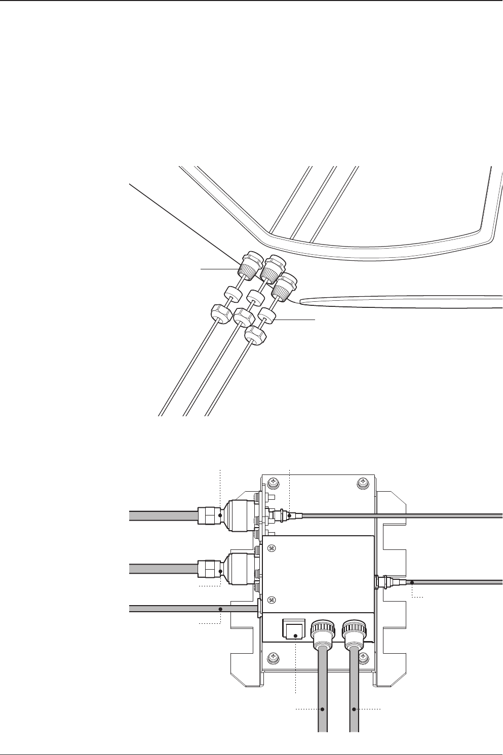
30
Modem Tx Cable
(from modem)
ACU Rx Cable
(from ACU)
On/Off Switch
BUC Power Cable
(from ACU)
Antenna Power Cable
(from antenna)
Rotary #2 Rx Cable
(from antenna)
BUC Power Cable
(from antenna)
Rotary #1 Tx Cable
(from antenna)
Power Switch Box
Shrinkage Guide
Rubber Gland
RF Cable Connections
Ensure that the switch on the power switch box is off during the installation period.
When all the cables have been installed, turn on the switch.

31
INSTALLING THE ANTENNA
Secure the RF Cables
Using tie wraps supplied with radome, secure the RF cables connected to the
power switch box. Reinstall the hatch to the radome after the cable connection is
established.
NOTE: Tightening torque
Connector Type Tightening Torque
F Type 1.0 N-m
SMA 0.6 N-m
N Type 1.5 N-m

INSTALLING THE ACU
Mounting the ACU
19” Rack Mount Type
Table Mount Type
ACU Dimensions
Selection of ACU Installation Site
Ship Gyrocompass Connection
Connecting the System with a Ship’s Gyrocompass
Connecting the System without a Ship’s Gyrocompass
ACU Connector Guide
PC to ACU Communication Setup
Wi-Fi Connection
33
INSTALLING THE ACU
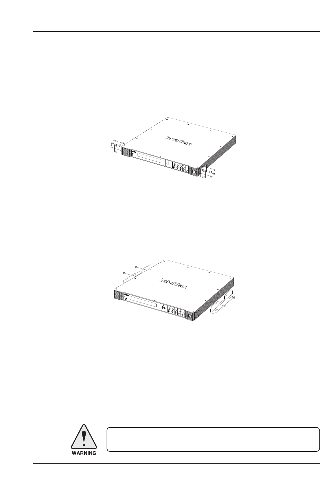
Mounting the ACU
Intellian supplies two types of mounting methods (a) 19” Rack Mount Type and (b)
Table Mount Type to mount your ACU.
19” Rack Mount Type
- The ACU should be installed using the two supplied rack mounting brackets which
allow for a side 19” rack mounting conguration.
- Using the self tapping screws supplied, attach the mounting brackets to the sides
of the ACU.
- Place the ACU in the location where it is going to be installed.
- Connect the cables to the rear of the ACU.
Table Mount Type
- The ACU should be installed using the two supplied table mounting brackets
which allow for a top or bottom mounting conguration.
- Using the self tapping screws supplied, attach the mounting brackets to the sides
of the ACU.
- Place the ACU in the location where it is going to be installed.
- Using a pencil to mark the 4 hole positions (2 each side), and use the appropriate
drill bit to mount the unit.
- Connect the cables to the rear of the ACU.
WARNING: Ensure that the cables connected to the ACU are long enough to prevent
damage when the ACU is pulled out from the rack.
19" Rack Mount Type
Table Mount Type
v130 – Marine Satellite Communication System
34
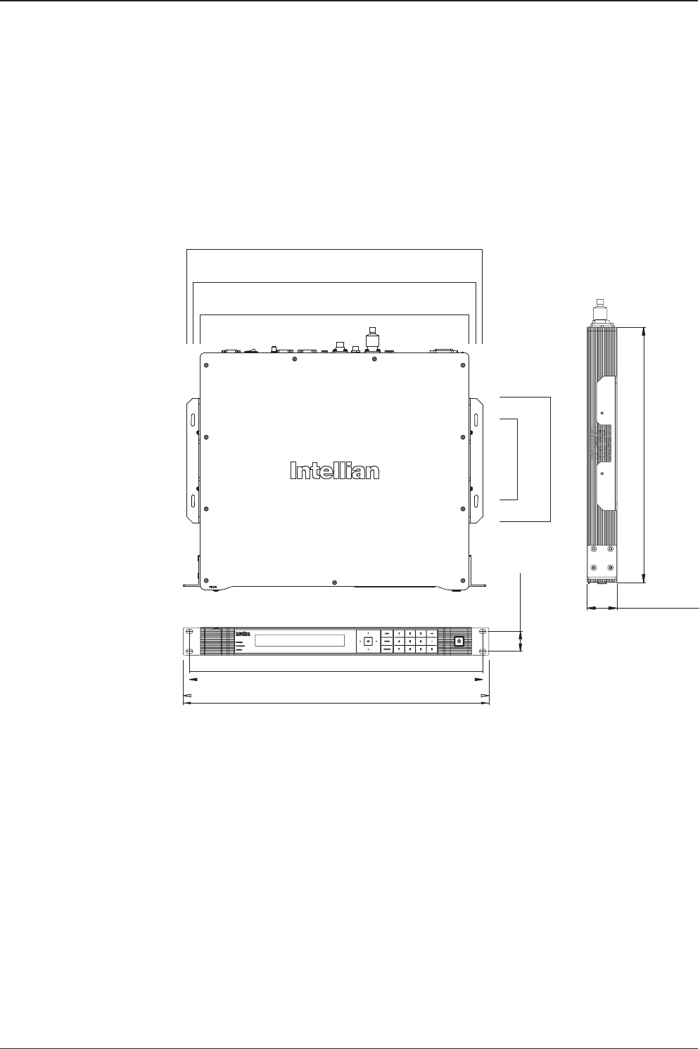
Selection of ACU Installation Site
The ACU should be installed below deck, in a location that is:
• Dry, cool, and ventilated.
• The front panel should be easy accessible to user.
13 cm (5.1")
20 cm (7.9")
43.1 cm (17")
45.4 cm (17.8")
47.4 cm (18.6")
4.4 cm (1.7")
38 cm (15")
48.5 cm (19.1")
46.6 cm (18.4")
3.2 cm (1.3")
ACU Dimensions
Dimension of ACU
35
INSTALLING THE ACU
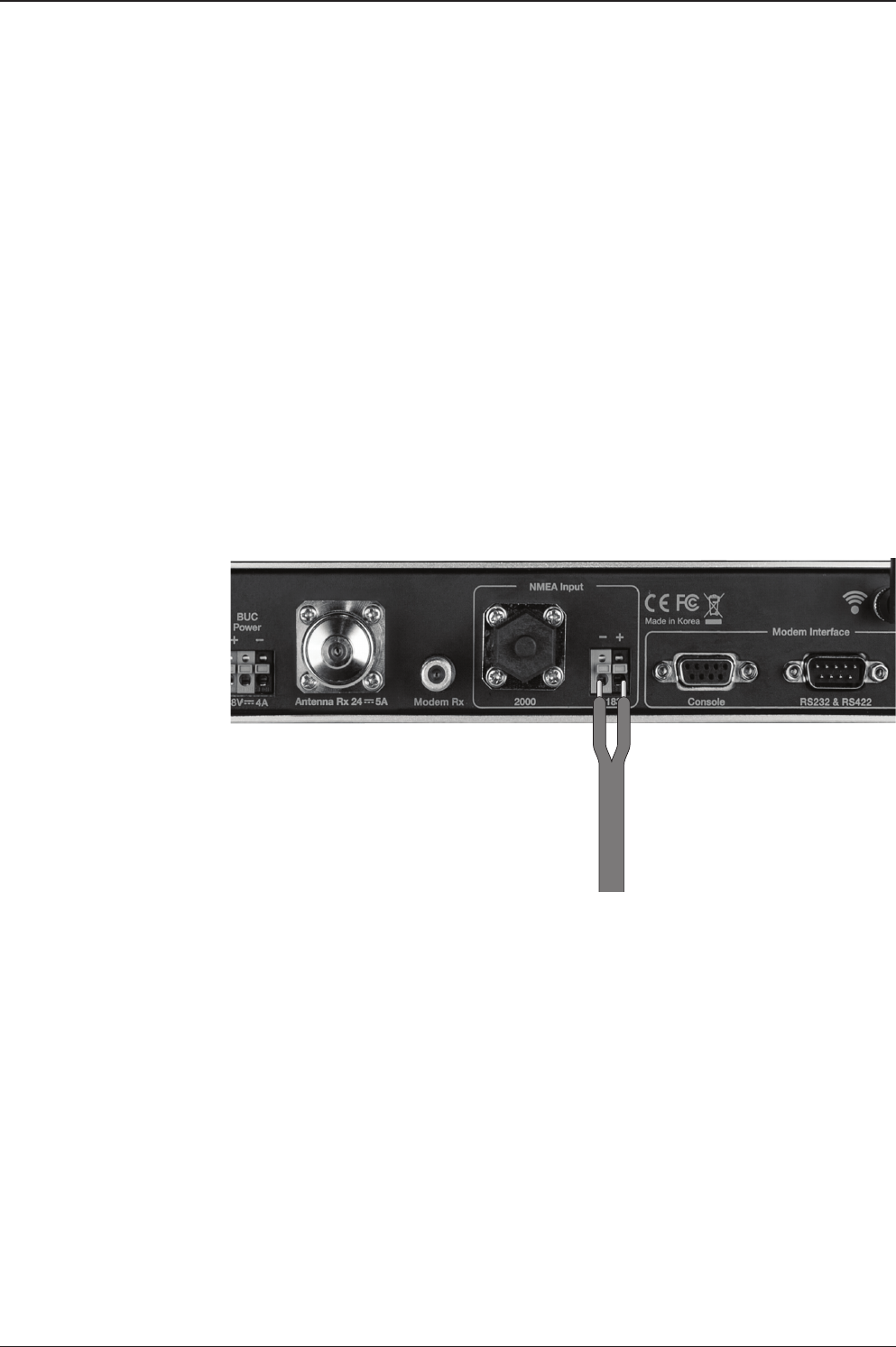
Ship Gyrocompass Connection
Connecting the System with a Ship’s Gyrocompass
The ship’s gyrocompass provides true heading input to the antenna which easily
allows the antenna to target and acquire the desired satellite. Therefore, Intellian
always recommend to connect a ship’s gyrocompass to the antenna through the
gyrocompass interface on the ACU. If the ship’s gyrocompass output is other than
NMEA 0183 and NMEA 2000, a purchase of an NMEA converter is required.
• NMEA 0183 Gyrocompass Interface Cable (Customer supplied)
• Connector Type: 2 conductors for NMEA 0183, 5 conductors for NMEA 2000
• NMEA heading sentence: xx HDT (4800 Baud, 8, N,1) If there is no HDT
sentence then use HDM sentence instead.
• NMEA 2000 heading PGN Number = 127250 (Vessel Heading)
Ship’s Gyrocompass
Connection
Strip the cable for 5 mm (0.2")
Do not solder the cable

v130 – Marine Satellite Communication System
36
Connecting the System without a Ship’s Gyro
For a vessel where the ship’s gyrocompass is not installed or is difcult to be
connected, the Intellian Gyro-Free satellite search function will be automatically
enabled to allow the antenna to lock onto the desired satellite without requiring an
external heading input.
The table below provides an example of the gyro-free satellite search algorithm.
The Search 1 or Search 3 satellite search pattern will be triggered according to the
existence of heading input and the setting of the heading device.
Search 1: The antenna will search for the target satellite by turning its azimuth
angle in CCW (Counter Clockwise) direction until the antenna receives
the lock signal from the modem or the DVB (Digital Video Broadcasting)
transponder of the target satellite is decoded by the antenna.
Search 3: The antenna will search for the target satellite by turning its azimuth angle
directly to the position calculated using the ship’s heading input and lock
onto the satellite.
Quick Setup Procedure
• Set the satellite with DVB transponder as the target satellite.
• Set “No Device” to the heading device.
• The antenna will search for the target satellite by turning its azimuth angle in CCW
direction and lock onto the satellite signal until the antenna receives a lock signal
from the modem or the DVB transponder of the target satellite is decoded.
• Set the heading device as NMEA/NMEA 2000
• Enter “Manual search” menu and press “Function” key to save the current settings.
Intellian ACU will automatically calculate and save the Bow offset.
• Upload the real TARGET satellite pre-congured from the library.
Setting of Heading Device
Existence of Heading Data No Device NMEA/
NMEA 2000
Ground Test
With Heading Data Search 1 Search 3 Search 3
Without Heading Data Search 1 Search 1 Search 3
37
INSTALLING THE ACU
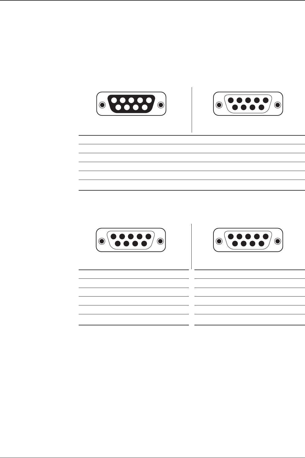
ACU Connector Guide
• Console Port
NOTE: NMEA GPS IN/OUT Sentence: GPGLL (4800 Baud, 8, N, 1)
12345
6789
54321
9876
12345
6789
54321
9876
12345
6789
54321
9876
Pin Signal Pin Signal
1GND 6GPS OUT -
2GPS OUT + 7MODEM_SIGNAL_IN
3MODEM_LOCK 8MODEM_CTRL2
4MODEM_CTRL1 (TX MUTE) 9GPS IN -
5GPS IN +
ACU Console Port
D-Sub 9 pin Female
D-Sub 9 pin Male connector
Supplied Component
Pin Signal Pin Signal
1-6-
2RXD 7-
3TXD 8-
4-9-
5GND
Pin Signal Pin Signal
1-6-
2RXD + 7RXD -
3TXD + 8TXD -
4-9-
5GND
D-Sub 9 pin RS232
Connector
D-Sub 9 pin connector
Supplied Component
• RS232/422 Connector (Modem & BUC Interface)

v130 – Marine Satellite Communication System
38
5
4
3
21Pins
Connector Threads
5
3
4
12Sockets
Connector Threads
Pin Signal
1Shield
2NET-S, (power supply positive, +V)
3NET-C, (power supply common, -V)
4NET-H, (CAN-H)
5NET-L, (CAN-L)
Pin Signal
1Shield
2NET-S, (power supply positive, +V)
3NET-C, (power supply common, -V)
4NET-H, (CAN-H)
5NET-L, (CAN-L)
Male Connector Female Connector
• NMEA 2000 Connector
39
INSTALLING THE ACU
PC to ACU Communication Setup
You can establish data communication between a PC and the ACU using one
of the following methods.
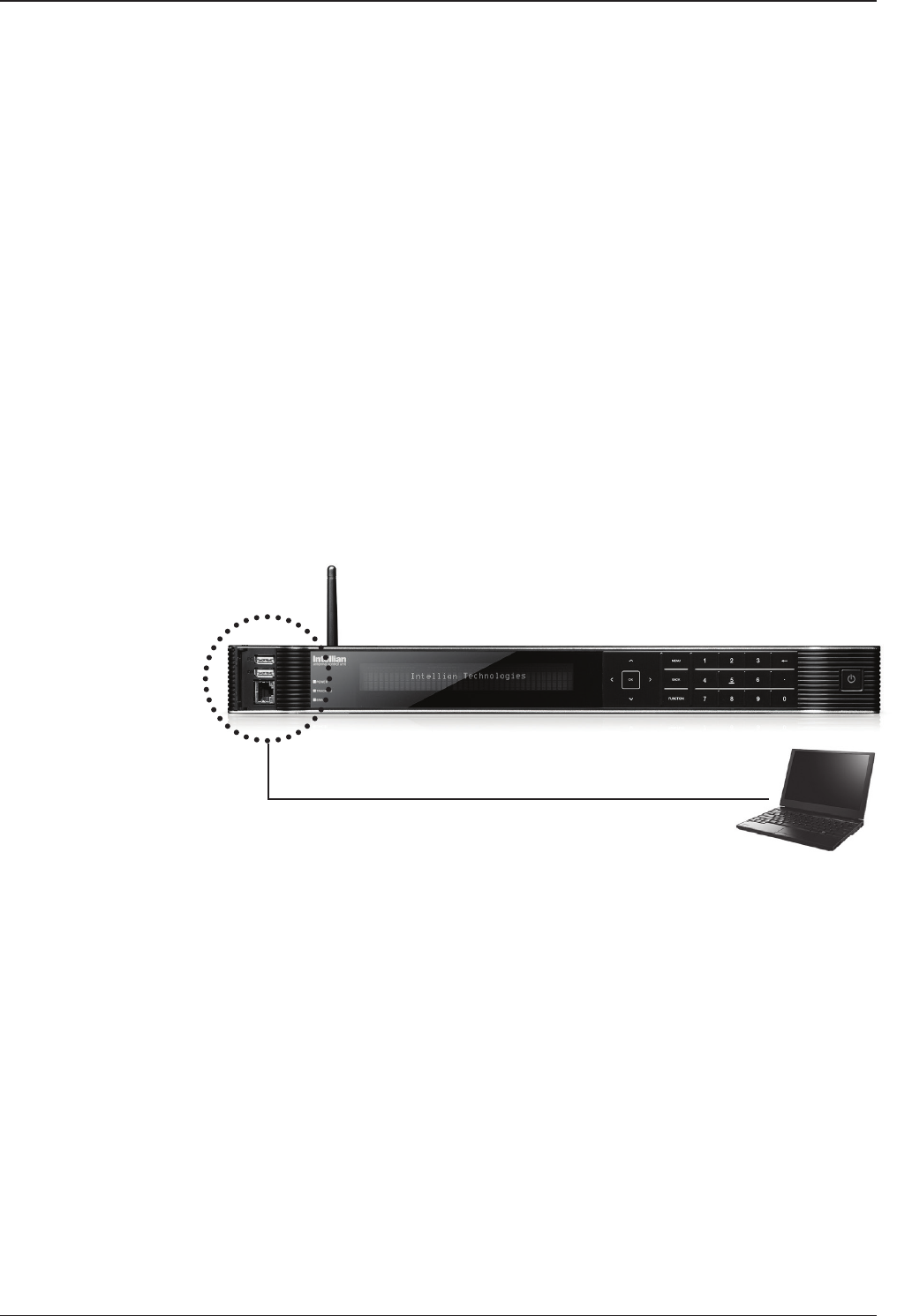
TCP/IP Connection
Connection through Front Panel Management Port
This method is most recommended. The network is automatically congured by
DHCP without the need of additional PC IP conguration.
1. Connect an Ethernet cable from a PC Ethernet port to the Management port
on the front of the ACU.
2. Network connection is established.
3. Use the following IP address to access Intellian Aptus® or Aptus Web page.
• 192.168.2.1 (Default)
Connection through Rear Panel Ethernet Port
This method requires separate IP conguration on a PC.
1. Connect an Ethernet cable from a PC Ethernet port to an available LAN port
of a Switch/Hub.
2. Go to Control Panel > Network and Sharing Center > Change Adapter Settings
and right-click on the Local Area Connection then click Properties
3. Select TCP/IPv4, then click Properties.
4. Change the network settings on a PC;
• IP: 192.168. 0.222 (Secondary: 10.10.1.2)
• Subnet Mask: 255.255.255.0
• Gateway: 192.168.0.223 (Secondary: 10.10.1.1)
5. Use the following IP address to access Intellian Aptus® or Aptus Web page.
• Default: 192.168.0.223 (Secondary: 10.10.1.1)
PC
Management
Ethernet Port
Ethernet Port

v130 – Marine Satellite Communication System
40
Serial/USB Connection
Connection through Serial Port
1. Connect a 9-pin Serial cable from the PC INTERFACE connector on the
ACU to the 9-pin serial port on your PC.
2. If there is not a 9-pin serial port on the PC, use a USB-Serial adapter.
Connection through USB Port
There are two USB(USB-to-Serial) ports are available on the ACU. One is on the
front and the other is on the rear.
1. Connect a USB cable from a USB port on your PC to the USB port
on the ACU.
Serial Connection
USB Connection
41
INSTALLING THE ACU
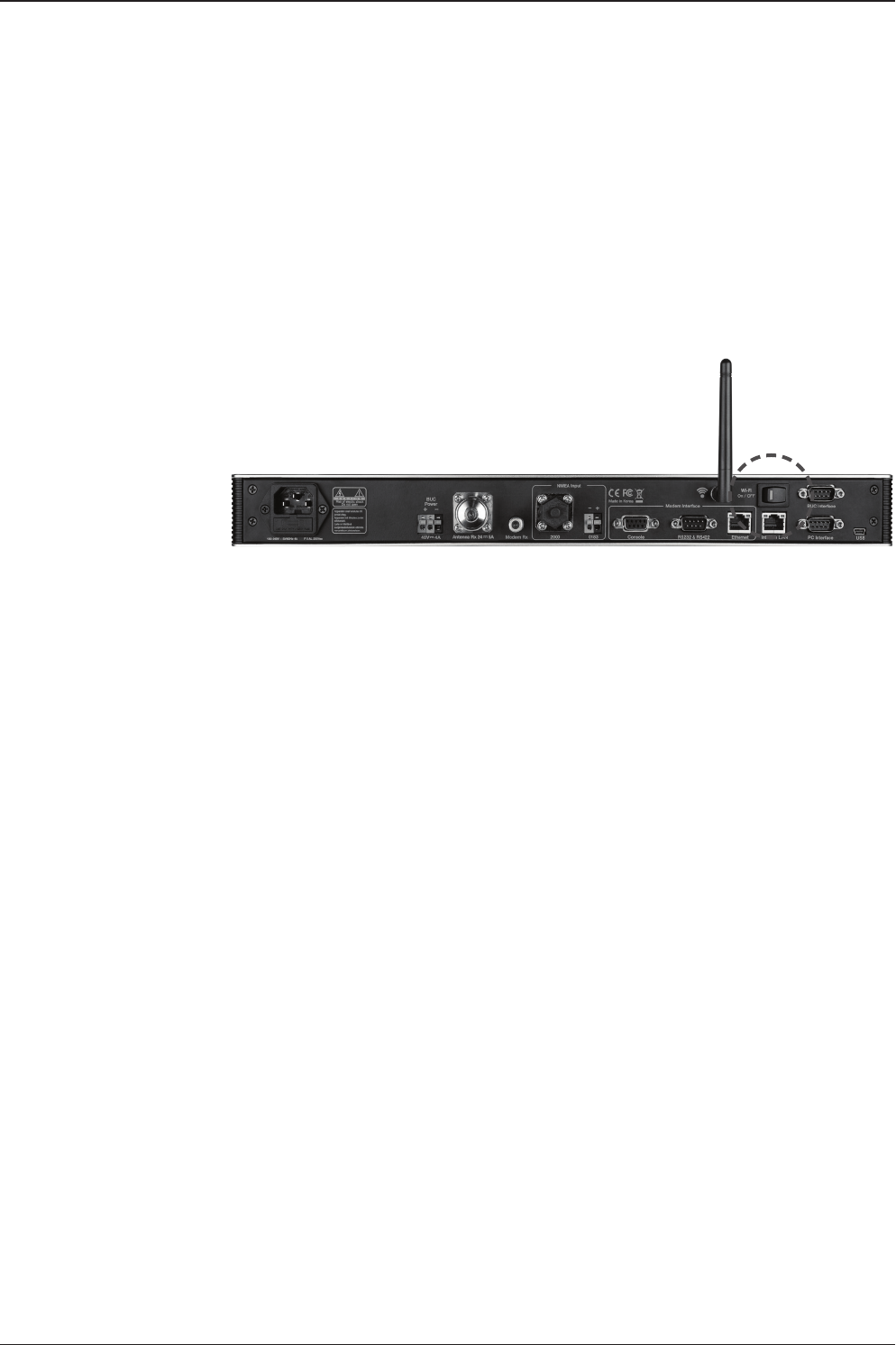
Wi-Fi Connection
1. Turning on the Wi-Fi switch
Turn on the switch on the back of the ACU, and 30 seconds after enabling the
power supply, conrm if a red light appears on the switch.
Setup Wi-Fi Connection
• Setting up the ACU in order to access Wi-Fi
• Setting up the PC (AP Mode) in order to access Wi-Fi
• Aptus Web Conrmation
Setting up the ACU in order to access Wi-Fi
v130 – Marine Satellite Communication System
42
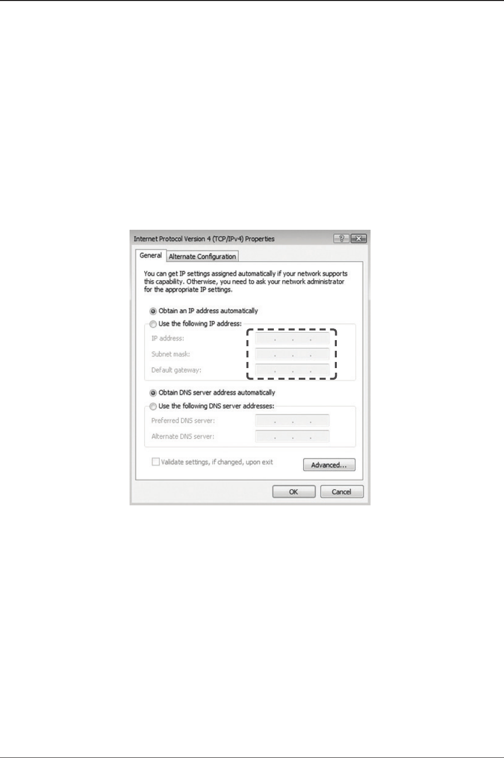
2. To manually change the network settings, click on "Use the following
IP address" and use the settings listed below.
Case #1
If iARM Module’s IP is known
The iARM module’s default IP is 192.168.1.223
PC IP : 192.168.1.222
Subnet Mask : 255.255.255.0
GateWay : 192.168.1.223
Case #2
iARM Module’s IP is unknown
The iARM module’s secondary IP is 10.10.10.1
PC IP : 10.10.10.2
Subnet Mask : 255.255.255.0
GateWay : 10.10.10.1
Setting up the PC in order to access Wi-Fi
1. Setting up my computer’s wireless IP address
- Control Panel> Network and Sharing Center > Change Adapter Settings >
Right click on the “Local Area Connection ”> Click Properties
After selecting TCP/IPv4, click on the properties menu, then select "Obtain an IP
address automatically."
43
INSTALLING THE ACU
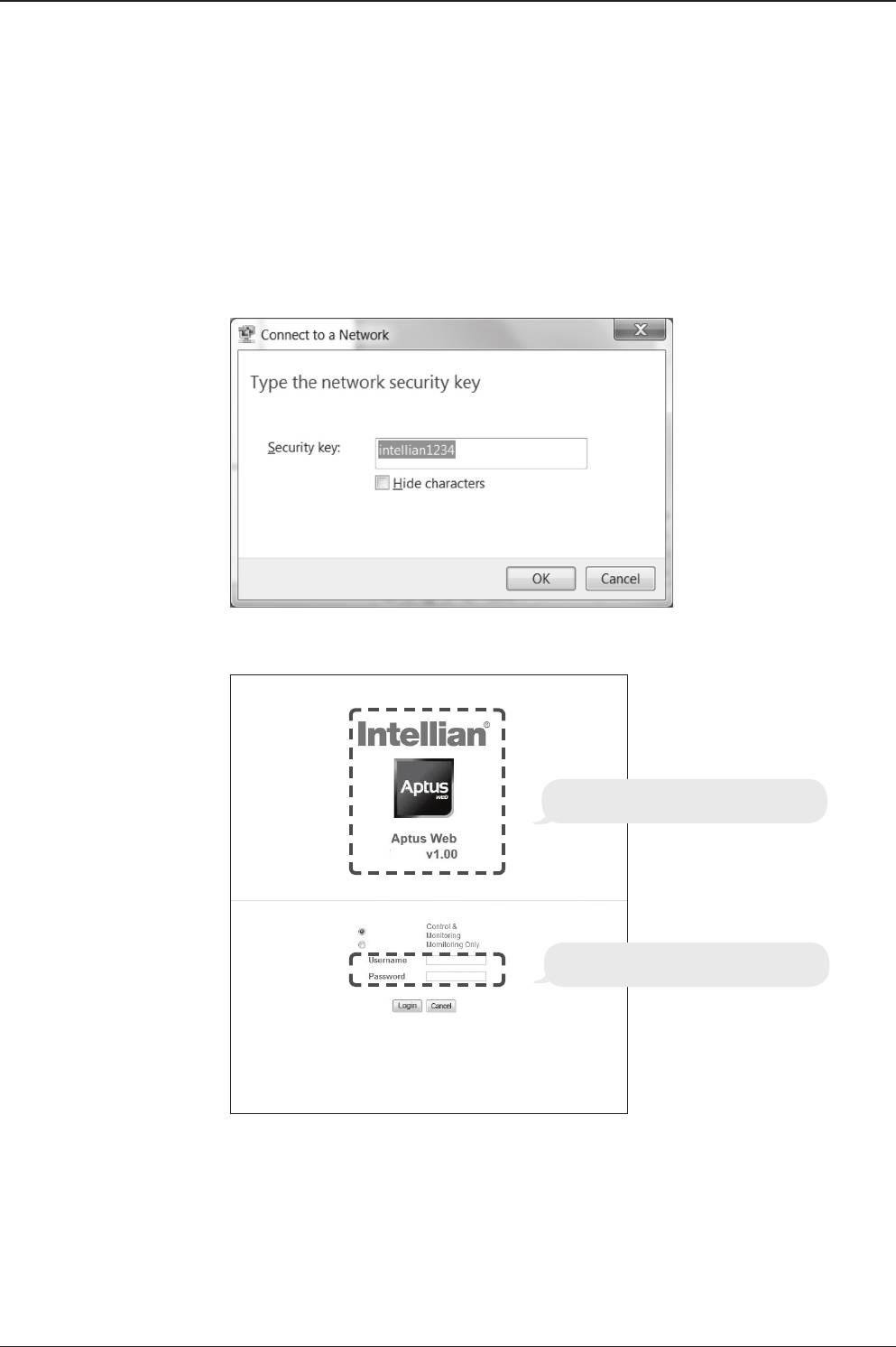
3. Connect Wi-Fi in AP mode.
After clicking on the Windows Wireless Connection icon, click on intellian-VSAT
(Default).
4. Enter the Network Security Key.
Key: intellian1234 (Default)
Login by entering the ID / Password listed below.
Username: intellian (Default)
Password: 12345678 (Default)
6. When you login, make sure that all the data within every page is being displayed
correctly.
5. You can conrm the logo and version data by accessing http://192.168.1.223
Aptus Web v X.XX
Login intellian / 12345678
v130

OPERATING THE ACUOPERATING THE ACU
Introduction
Normal Mode
Setup Mode
Installation Settings
Antenna Settings
Manual Search
Setup Antenna LNB pol Angle
Search Parameters
Setup Antenna Parameters
Setup Block Zone
Antenna Diagnostic Test
Satellite Settings
Load Satellite
Edit Satellite Information
Add Satellite Information
Check NID
System Settings
Set LNB Local Oscillator Frequency
Set Location
Set Modem Port
System Management
45
OPERATING THE ACU
This section of the handbook describes how to set up your system after installation
using the ACU.
Introduction
WARNING: Please ensure that your Intellian system is ALWAYS powered ON upon
leaving the dock. Failure to follow these instructions could result in damaging mechanical
parts in the antenna and/or possibly void your warranty. Intellian strongly recommends
to restrain the antenna pedestal properly while underway when power is removed from
the antenna. The normal operating condition is to remain powered up at all times.
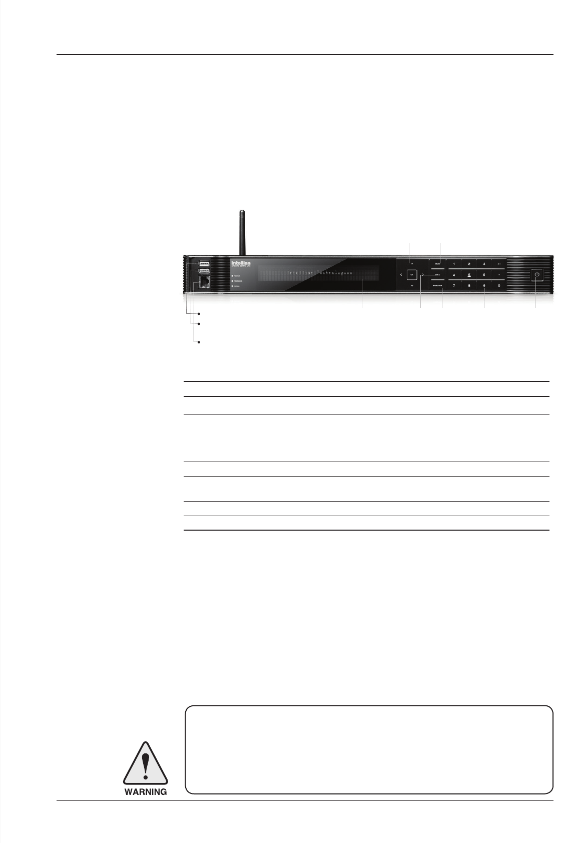
ACU Soft Keys
Soft key Function
MENU Enter SETUP mode
BACK
In SETUP mode: returns to the previous menu / option or save
the adjusted settings.
In normal mode: returns to the rst page of the antenna's current
status.
FUNCTION Save the adjusted settings.
ARROW KEYS Select from the alternative options to increse or decrese the
selected character to the desired value.
OK Enter the next step / menu
NUMBER KEYS Input the numbers
Soft Key Functions
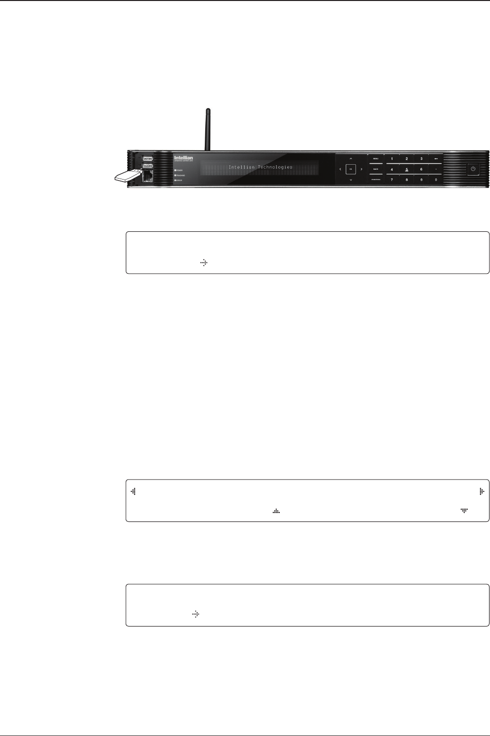
Status VFD BACK FUNCTION Number Keys Power
MENUArrow Keys
PC : PC Cable (USB)
DN : Firmware upgrade or
Log data download (USB)
Management Ethernet port

v130 – Marine Satellite Communication System
46
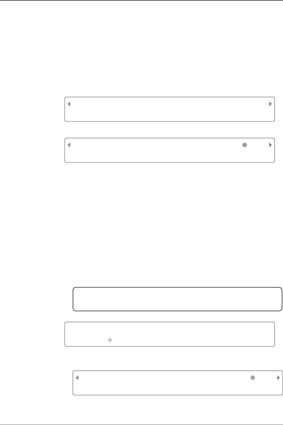
INTELLIAN TECHNOLOGIES INC.
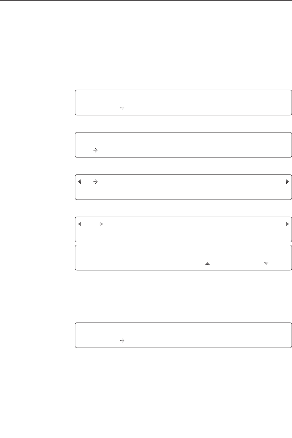
1. The data communication is being established between the antenna and the ACU.
INITIALIZE - ANTENNA INFO
INTELLIAN V130
2. The ACU receives antenna information.
INITIALIZE - EL POSITION
INTELLIAN V130
3. The elevation angle and cross level angle are initialized.
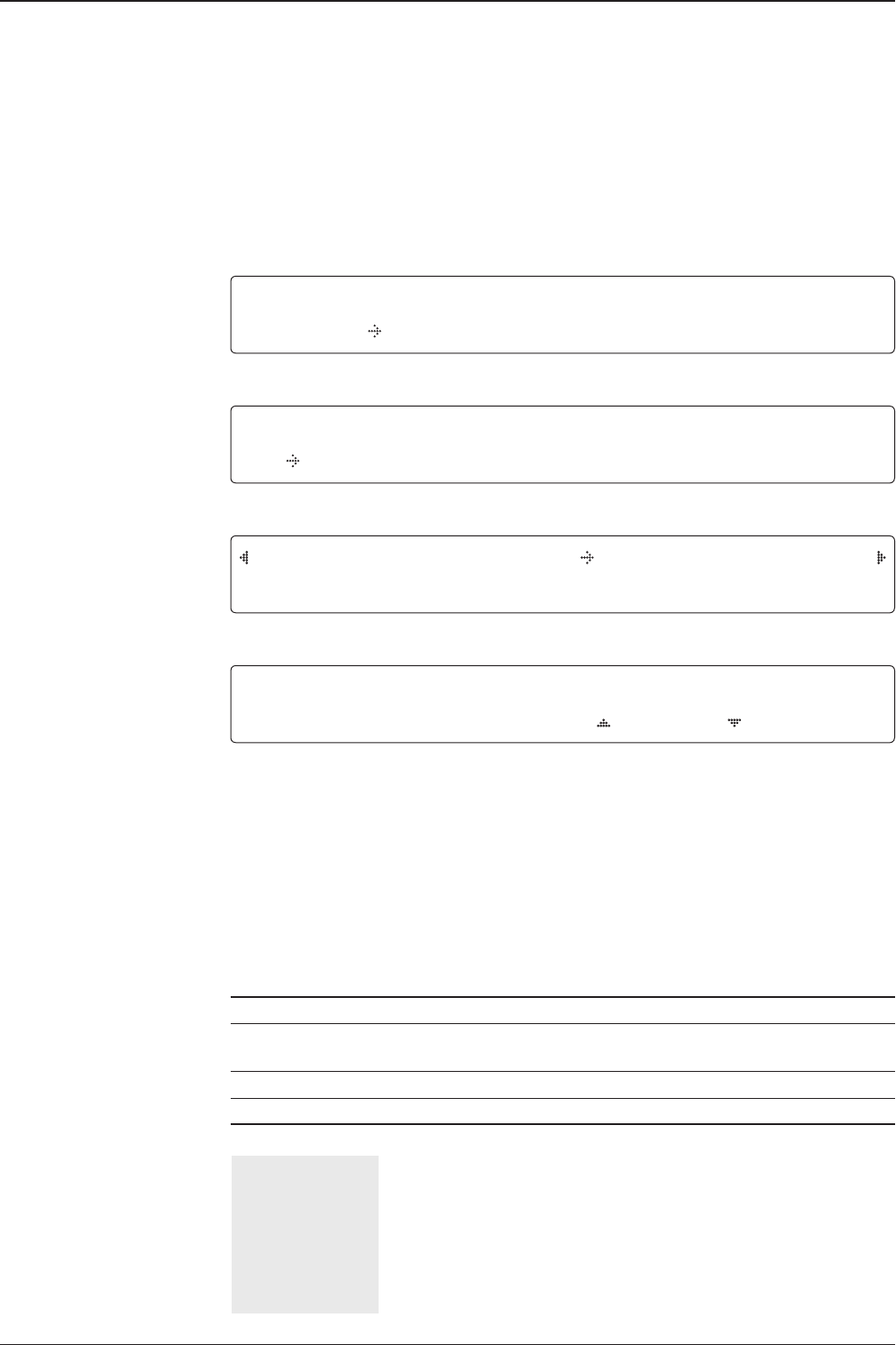
INITIALIZE - AZIMUTH POSITION
INTELLIAN V130
4. The azimuth angle is initialized.
INITIALIZE - SAT POSITION
INTELLIAN V130
5. The antenna returns to the target satellite position.
SEARCH1 138.0E TELST_18 SIG:301 VL
AZ:292.7( 202.7) EL: 48.3 SK: -72.0
6. The antenna is searching for the target satellite.
TRACKING 138.0E TELST_18 SIG:501 VL
AZ:292.7( 202.7) EL: 48.3 SK: -72.0 Fn
7. The antenna has locked onto the satellite.
Startup
With the system installed and power applied, the ACU screen will show the following
sequence.
Normal Mode
Start up
Initialize antenna info
Initialize elevation &
cross level angle
Initialize azimuth angle
Initialize target satellite
position
Search status
Tracking status
47
OPERATING THE ACU
SEARCH1 138.0E TELST_18 SIG:301 VL
AZ:292.7( 202.7) EL: 48.3 SK: -72.0
1. The antenna is searching for the target satellite.
TRACKING 138.0E TELST_18 SIG:301 VL
AZ:292.7( 202.7) EL: 48.3 SK: -72.0 Fn
2. The antenna has locked onto the target satellite.
Current IF signal level (SIG/AGC) is displayed. SIG will be displayed when NBD (Narrow band
detection) mode for TRACKING SIGNAL is chosen to be used and AGC will be displayed
when DVB mode of TRACKING SIGNAL is chosen to be used.
The symbol “•” will be only displayed when the satellite signal is strong enough to locked
onto. [VL] indicates the LNB's local frequency corresponding to 13V is in use for the signal
reception.
VL: 13V + 0 kHz, HL: 18V + 0 kHz, VH: 13V + 22 kHz, HH: 18V + 22 kHz
True azimuth [292.7] position of the antenna is the sum of ships heading 090.0 [HDG] and
antenna relative [202.7].
SAVE CURRENT SAT INFO ?
YES NO
3. Press FUNCTION key to save current satellite information or abort and return to the main
display. "Fn" will be displayed only if the antenna is in tracking mode.
4. Press RIGHT arrow key to display NBD, GPS and ship's heading information.
NOTE: However, if the "GYRO TYPE" is set to "NONE" or "NMEA" but without
receiving a proper input signal, "---.-" will be displayed at "True Azimuth"
Monitoring Antenna Current Status
When the ACU power is on, it displays the status of the antenna. The current status
of the antenna is displayed as shown below.
Current search status
Current tracking status
Save current satellite info
TRACKING 138.0E TELST_18 SIG:301 VL
AZ:---.-( 202.7) EL: 48.3 SK: -72.0 Fn
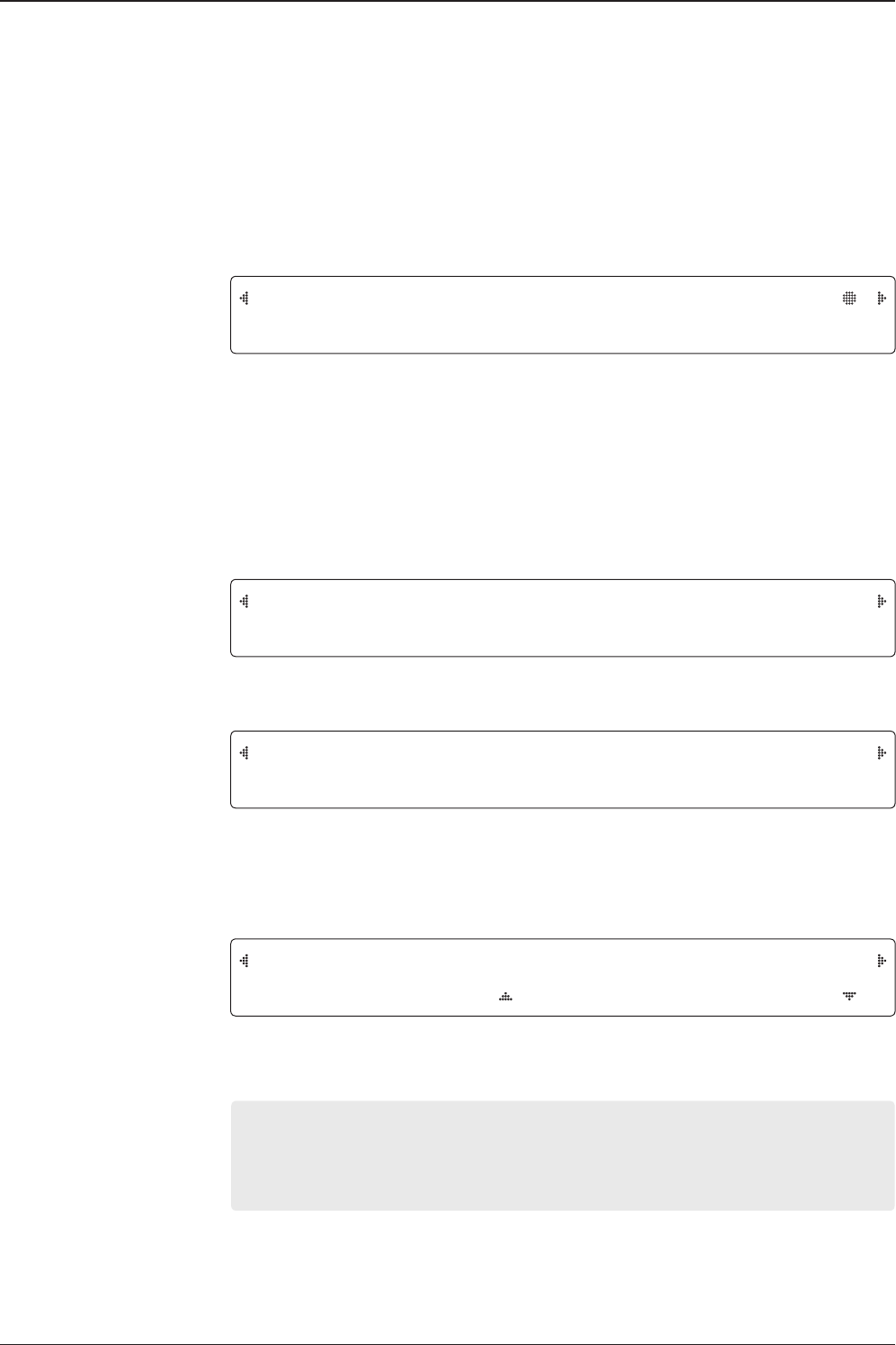
v130 – Marine Satellite Communication System
48
NBD F:1247000 BW:1000 SIG:301
004.53E 52.22N HDG:090.0 L:10000 Fn
5. NBD, GPS and ship’s heading information are shown.
- NBD (Narrow Band Detection) IF tracking frequency: 1247000 kHz
- Detected Band Width: 1000 kHz
- SIG (Signal Level ): 301 (When NBD mode for tracking signal is chosen)
- W (West)/E (East) Longitude: 4.53º E
- N (North)/S (South) Latitude: 52.22º N
- HDG (Ship’s Heading): 90º
- LNB local oscillator (LO) frequency: 10000 MHz
[PWR] ANT: 26.4V LNB: 13V + 0KHZ
ACU: 27.1V [POL] TX:V RX:H
6. Press RIGHT arrow key to display the current operation voltage for antenna, ACU and
LNB. POL indicates the TX polarity (VERTICAL) and RX polarity (HORIZONTAL).
V1-131-AFW ANT. SERIAL 1.00/1.00
VP-T506 ACU SERIAL 1.00
7. Press RIGHT arrow key to display the below information.
- Antenna part number, antenna serial number and PCU rmware version.
- ACU part number, ACU serial number, and ACU rmware version.
Press BACK Key to return to the rst page of the antenna current status.
Tracking & Heading
information
Power status
Antenna & ACU
versions
8.Touch RIGHT arrow key to display the USB FUNCTION*
This menu will be displayed automatically if a USB ash drive is plugged into the USB port
located in the front panel of the ACU.
USB FUNCTION*
• UPGRADE FIRMWARE: upgrade the system by using the rmware les
(les format: *.FWP) from the specied folder in the USB ash drive.
• COPY LOG DATA: Copy the up-to-date log data from the system to the USB ash drive.
Select
USB
functions
[USB FUNCTION] SELECT USB FUNCTION
UPGRADE FIRMWARE
49
OPERATING THE ACU
10. Press RIGHT arrow key to display the real-time diagnostic result.
The real-time diagnostic code will be displayed automatically if there is any error found
during the system operation. However, this page will not be displayed if there is no error
message.
11. Press FUNCTION key to erase diagnostic error message.
[DIAGNOSTIC] SENSOR BOX
CODE109 RESULTS : FAILED FN
ERASE DIAGNOSTIC ERROR LOG ?
YES NO
Erase
Error message
Real-time
diagnostic
result
USB
9. Touch OK key to upgrade rmware.
Refer to the error messages below if any errors occur.
UPGRADE FIRMWARE
- FIRMWARE FILE NOT FOUND: the system cannot nd the FWP le.
- INVALID FIRMWARE: the le is not in a recognizable FWP format.
- MORE THAN 1 FILE EXIST: there is more than 1 rmware le that exists from the
specied folder in the USB ash drive.
- CHECK USB CONNECTION: the USB ash drive is not connected.
COPY LOG DATA
- COPY LOG DATA TO USB [30%]: display the copy progress in percentages.
- NOT ENOUGH SPACE IN USB: USB occupies no memory space.
- CHECK USB CONNECTION: the USB ash drive is not connected.
Upgrade
the system UPGRADE ?
YES NO

v130 – Marine Satellite Communication System
50
Setup Mode
Enter the SETUP mode simply follow the instructions below.
Searching / Tracking mode
Enter password
Setup mode
Exit setup mode
TRACKING 138.0E TELST_18 SIG:301 VL
AZ:292.7( 202.7) EL: 48.3 SK: -72.0 Fn
1. While the antenna is in SEARCHING / TRACKING mode, press MODE key to enter SETUP
mode. * indicates the key pad lock function is on (Refer to KEY LOCK menu to setup the key
pad lock function). When key pad lock function is activated press MODE key or when “Fn”
menu is activated press FUNCTION key the ENTER PASSWORD menu will be displayed.
ENTER PASSWORD
- - - -
2. If the key pad lock function is on, enter the password before accessing to the SETUP
mode. If the key pad lock function is off, access to the SETUP mode directly as Step 3.
SETUP MODE ?
YES NO
3. Press LEFT arrow key to move cursor to YES and press OK key to enter SETUP mode or
press RIGHT arrow key to move cursor to NO and press OK key to abort and return to the
main display.
EXIT SETUP MODE ?
YES NO
4. While the antenna is in SETUP mode, press FUNCTION key as shortcut key to exit SETUP
mode.

51
OPERATING THE ACU
Installation Settings
During the rst time installation, it is required to setup the installation settings.
Installation
menu
Latitude & Longitude
Gyro type
Select satellite
Setup mode SETUP MODE ?
YES NO
1. Press LEFT arrow key to move cursor to YES and press OK key to enter SETUP mode
+ANTENNA +SATELLITE
+SYSTEM +INSTALLATION
2. Press arrow keys to move cursor to INSTALLATION menu and press OK key to enter it.
SELECT SATELLITE
[1] TELST_18 138.00E
3. Press UP and DOWN arrow keys to select the satellite that you wish to track and press OK
key to load the selected satellite.
LATITUDE LONGITUDE
37.00N 126.53E
4. Set the current LATITUDE and LONGITUDE
Press LEFT and RIGHT arrow keys until the desired character is underscored (selected).
Press UP and DOWN arrow keys to increase or decrease the value. Or press NUMBER keys
to set the desired value directly. Press OK key to set the parameter.
GYRO TYPE BOW OFFSET
NMEA 000
5. Set the ship’s GYRO TYPE* & BOW OFFFSET.
A search pattern 1 or 3 will be initiated according to which Gyro Type is selected and the
existence of the gyro input. Ensure that the supported Gyro Type is set correctly.If the ship's
gyrocompass output is other than NMEA0183 and NMEA2000, a separate purchase of an
NMEA converter is required.
A search pattern 1 will be initiated automatically if the gyro input does not exist and the gyro
type is selected other than GROUND TEST.
The BOW OFFSET is to offset the angle difference between the antenna’s bow and the ship’s
bow (Range: 0 – 360°).
NOTE: The bow offset will not be saved automatically if Search 1 pattern is initiated. In this case, the
antenna will need to retarget the desired satellite using Search 1 every time if the antenna restarts.

v130 – Marine Satellite Communication System
52
6. Set MODEM TYPE* and LNB LOCAL.
MODEM TYPE is to select a proper data communication port on the ACU to interface with
the satellite modem.
18V + 0kHZ 13V+22kHz
10750MHz 11300MHz
18V +22kHz
11300MHz
7. Set the LNB local oscillator frequency for each voltage power. (13V +0 kHz, 18V +0 kHz,
13V +22 kHz, 18V +22 kHz)
Press LEFT and RIGHT arrow keys until the desired character is underscored (selected).
Press UP and DOWN arrow keys to increase or decrease the value. Or press NUMBER keys
to set the desired value directly.
MODEM TYPE*
USER SETTING
IDIRECT-I/O
IDIRECT-AMIP
COMTECH-I/O
COMTECH-ROSS
HUGHES
SATLINK-SEIRAL
ELEKTRIKOM-AMIP
GILAT-SE-II
Modem Type & LNB Local
GYRO TYPE*
NO DEVICE
NMEA / NMEA 2000
GROUND TEST
Gyro search mode Setting of Heading Device
Existence of Heading Data No
Device
NMEA/
NMEA2000
Ground Test
With Heading Data Search 1 Search 3 Search 3
Without Heading Data Search 1 Search 1 Search 3
MODEM TYPE 13V + 0kHz
IDIRECT-I/O 10000MHz
53
OPERATING THE ACU
TRACKING 138.0E TELST_18 SIG:301 VL
AZ:292.7( 202.7) EL: 48.3 SK: -72.0 Fn
10. Antenna has locked onto the target satellite.
Tracking status
LOADING ...
DO NOT TURN OFF !
9. Setting is being loaded to the system.
The ACU will restart the system automatically after uploading the setting.
DO NOT TURN OFF ACU POWER while the data is being uploaded.
Loading settings
LOAD ?
YES NO
8. Press BACK key to load the current setting or abort and return to the main display.
Load

v130 – Marine Satellite Communication System
54
Antenna Settings
Manual Search
Search the desired satellite manually.
Antenna movement
Setup mode
Save
Manual search menu
Antenna menu
SETUP MODE ?
YES NO
1. Press LEFT arrow key to move cursor to YES and press OK key to enter SETUP mode.
+ANTENNA +SATELLITE
+SYSTEM +INSTALLATION
2. Press OK key to enter ANTENNA menu.
+MANUAL SEARCH +SET POL ANGLE
+SEARCH PARAM +SET PARAMETERS
3. Press OK key to enter MANUAL SEARCH menu.
STEP SIZE AZIMUTH ELEVATION AGC
# 00.2 # 231.7 48.3 301 Fn
4. Current IF tracking signal level (AGC) / (SIG) is displayed to assist you in manually peaking
AZIMUTH (0°-360°) and ELEVATION (0°-90°) angle for best signal level.
Press NUMBER key to change the STEP SIZE (Range: 0.1~99.9). Press LEFT and RIGHT
arrow keys to increase or decrease the azimuth angles. Press UP and DOWN arrow keys to
increase or decrease the elevation angles.
Press FUNCTION key to save current settings or abort and return to the main display.
SAVE CURRENT SAT INFO?
YES NO
5. If the current settings are able to locate the satellite, press FUNCTION key to save “current
satellite information”. This will help to reduce the satellite acquisition time after restarting
the system. Press LEFT arrow key to move cursor to YES and press the OK key to save the
settings.
NOTE: If the gyro type is not ground test or the gyro is not connected to the ACU, the information cannot
be saved.

55
OPERATING THE ACU
Setup Antenna LNB pol Angle
LNB pol angle type
Setup mode
Set pol angle menu
Antenna menu
LNB pol angle Signal
Mechanical Skew
Offset
SETUP MODE ?
YES NO
1. Press LEFT arrow key to move cursor to YES and press OK key to enter SETUP mode.
+ANTENNA +SATELLITE
+SYSTEM +INSTALLATION
2. Press OK key to enter ANTENNA menu.
+MANUAL SEARCH +SET POL ANGLE
+SEARCH PARAM +SET PARAMETERS
3. Press RIGHT arrow key to move cursor to SET POL ANGLE menu and press OK key to
enter it.
SELECT LNB POL. ANGLE ME NU
CALIBRATION
4. Press UP and DOWN arrow keys to select the LNB pol angle menu and press OK key to
run the selected operation'CALIBRATION', 'MANUAL ADJUST' or 'RESET MECHANICAL
OFFSET'.Select MANUAL ADJUST to control LNB pol angle manually. If the control board,
LNB pol potentiometer or belt is replaced, select CALIBRATION to calibrate LNB pol angle.
LNB POL ANGLE SIGNAL: 180
20.1
5. Press UP and DOWN arrow keys to increase or decrease the LNB pol angle manually and
the correspondent SIGNAL level will be displayed next to it. Press BACK key to return to the
main display.
NOTE: LNB POL ANGLE menu will be displayed only if MANUAL ADJUST is selected.
SELECT LNB POL.ANGLE MENU
RESET MECHANICAL OFFSET
6. Press OK keys to reset the mechanical skew offset.
v130 – Marine Satellite Communication System
56
Search Parameters
Setup mode
Manual search menu
Antenna menu
Search param
Search 1 range
Search 3 range
SETUP MODE ?
YES NO
1. Press LEFT arrow key to move cursor to YES and press OK key to enter SETUP mode.
+ANTENNA +SATELLITE
+SYSTEM +INSTALLATION
2. Press OK key to enter ANTENNA menu.
+MANUAL SEARCH +SET POL ANGLE
+SEARCH PARAM +SET PARAMETERS
3. Press arrow keys to move cursor to SEARCH PARAM menu and press OK key to enter it.
SEARCH WAIT TIME INCREMENT STEP
030 0.50
4. Set SEARCH WAIT TIME and INCREMENT STEP.
Set the time-out for automatic initiation of a search after the signal level drops below
the predened threshold value (Range : 1 - 120 sec) and set increment step size
(Range : 0.01 – 5.00 sec)
SEARCH1 AZ SEARCH1 EL
400 06
SEARCH3 AZ SEARCH3 EL
003 04
4. Set SEARCH 1 and 3 AZ (Azimuth) range and EL (Elevation) range. SEARCH 2 is reserved
for future use.
A search pattern 1 or 3 will be initiated according to which GYRO TYPE is selected and the
existence of the gyro input.
Search 1: a search pattern 1 will automatically be initiated when the ship’s heading input does
not exist / is failed. The antenna will go to the relative azimuth position 0º at the calculated
elevation and search in the azimuth CCW direction and search up +0.5º & down -0.5º with a
total 6º(±3º) in elevation. The search cycle will repeat until the antenna receives the lock signal
from the modem or the DVB transponder of the target satellite is decoded by the antenna.
If the desired signal is found and above the predened detect level, the ACU will enter to
Search 3. However, the antenna will not initiate Search 3 pattern but go into TRACKING
mode immediately if the desired signal is above the predened tracking threshold level. If the
detected signal is below the predened tracking threshold level, the search 1 will repeat and
start 3º away from the current position.
57
OPERATING THE ACU
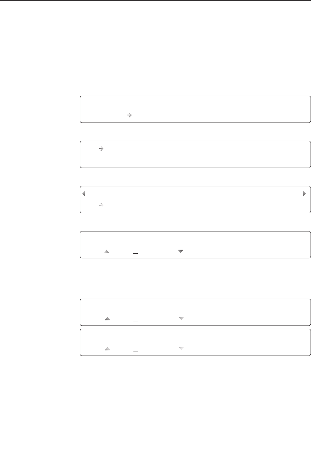
-3°
-2°
-1°
0°
1°
2°
3°
1 5 10 15 20 3025
Search 1 (Gyro Free) Search Pattern
Search 3 pattern
Elevation
(EL) Range
0.5˚
Azimuth (AZ) Range
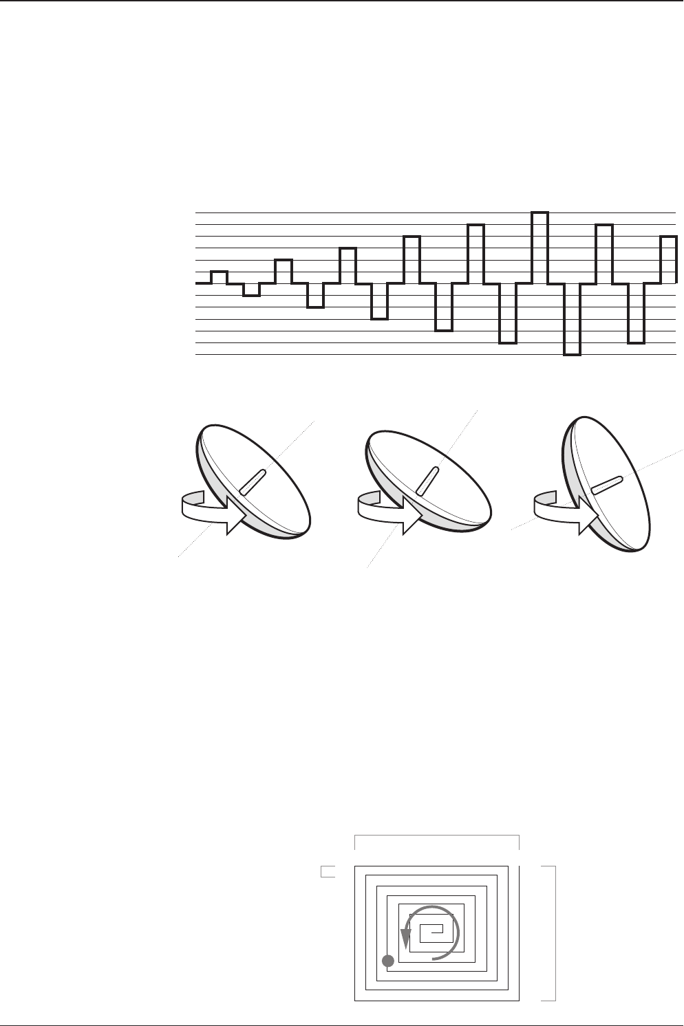
Search 3: a search pattern 3 will automatically be initiated when AGC / SIG falls
below the current tracking level threshold value. If the desired signal is found and
above the predened tracking level, the ACU will terminate Search 3 and go into
TRACKING mode. A search pattern will automatically be initiated when AGC / SIG
falls below the current threshold setting (indicates that satellite signal has been
lost). Search is conducted in a two-axis pattern consisting of alternate movements
in azimuth (AZ) and elevation (EL) as forming expanding square indicated as below
diagram.
Target Satellite EL Position
Revolution (AZ direction)
Target EL Angle
Turn 1
Target EL Angle + 0.5°
Turn 2
Target EL Angle - 0.5°
Turn 3
Search 1 antenna motion

v130 – Marine Satellite Communication System
58
Password
Antenna menu
Set parameters menu
Setup mode
Set detect & tracking DVB
Setup Antenna Parameters
These parameters should only be changed by an authorized service technician.
Improper setting of these parameters will cause your system to perform improperly.
SETUP MODE ?
YES NO
1. Press LEFT arrow key to move cursor to YES and press OK key to enter SETUP mode.
+ANTENNA +SATELLITE
+SYSTEM +INSTALLATION
2. Press OK key to enter ANTENNA menu.
+MANUAL SEARCH +SET POL ANGLE
+SEARCH PARAM +SET PARAMETERS
3. Press arrow keys to move cursor to SET PARAMETERS menu and press OK key to enter it.
ENTER PASSWORD
- - - -
4. Press 4 digit password to enter SET PARAMETERS menu (1590).
Setup parameters is only required after installation or repairs of your antenna system.
These parameters should only be changed by an authorized service technician.
Improper setting of these parameters will render your system inoperable.
DETECT DVB TRACKING DVB
040 020
5. Set DETECT DVB and TRACKING DVB when DVB mode of TRACKING SIGNAL is chosen
to be used (Range: 1-200).
DETECT DVB is to set the satellite signal detection level and TRACKING DVB is to set the
satellite signal tracking level.
Press LEFT and RIGHT arrow keys until the desired character is underscored (selected).
Press UP and DOWN arrow keys to increase and decrease the selected character.
Or press NUMBER keys to set the desired value directly. Press OK key to set the parameter.
Press BACK key to select the parameter you wish to edit and press BACK key again to save
or abort and return to the main display.
59
OPERATING THE ACU
Detect & tracking level
Set detect & tracking NBD
BOW & EL adjust
DETECT NBD TRACKING NBD
040 020
6. Set DETECT NBD and TRACKING NBD when NBD (Narrow band detection) mode of
TRACKING SIGNAL is chosen to be used (Range: 1-200).
DETECT NBD is to set the satellite signal detection level and TRACKING NBD is to set the
satellite signal tracking level.
Press LEFT and RIGHT arrow keys until the desired character is underscored (selected).
Press UP and DOWN arrow keys to increase and decrease the selected character.
Or press NUMBER keys to set the desired value directly. Press OK key to set the parameter.
Press BACK key to select the parameter you wish to edit and press BACK key again to save
or abort and return to the main display.
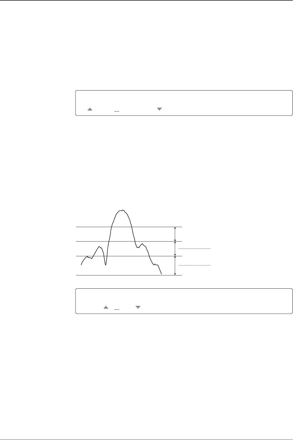
Noise Level
Detect Level
Tracking Level
TRACKING DVB/NDB
Peak Level
DETECT DVB/NDB
BOW OFFSET EL.ADJUST
000 +0.0
7. Set BOW OFFSET and EL. ADJUST
BOW OFFSET is to offset the angle difference between the antenna’s bow and the ship’s bow
(Range: 0 – 360°) and EL. ADJUST is to offset the angle difference between the mechanical
elevation angle and actual elevation angle (Range: ± 5°).
Press LEFT and RIGHT arrow keys until the desired character is underscored (selected).
Press UP and DOWN arrow keys to increase and decrease the selected character.
Or press NUMBER keys to set the desired value directly. Press OK key to set the parameter.
Press BACK key to select the parameter you wish to edit and press the BACK key again to
save or abort and return to the main display.

v130 – Marine Satellite Communication System
60
Select operation process OPERATION
SAVE
8. Set OPERATION.
Press UP and DOWN arrow keys to select OPERATION items.
SAVE: save and execute the current settings.
The antenna is balanced at factory. However, after disassembly for shipping, maintenance or
parts replacements, antenna balance adjustment may be required. The elevation and cross-
level motors have a brake mechanism integrated into them, therefore, antenna power and
IDLE MODE must be ON to release the motor brakes. Balancing is achieved by adding or
removing weight blocks at strategic locations to keep the antenna balanced.
IDLE MODE: Press UP and DOWN arrow keys to turn ON/ OFF IDLE MODE.
The motor brakes will be released while the IDLE MODE is ON. The antenna will restart
automatically if IDLE MODE is re-set from ON to OFF or BACK key is pressed to exit SETUP
mode.
REBOOT ANTENNA: The antenna will restart automatically if REBOOT ANTENNA is ON.
OPERATION*
SAVE
IDLE ON / OFF
REBOOT

61
OPERATING THE ACU
Setup Block Zone
Up to 5 block or radiation hazard zones can be programmed with relative azimuth
and elevation sectors.
Block zone menu
Block zone range
Block zone 1
Antenna menu
Setup mode SETUP MODE ?
YES NO
1. Press LEFT arrow key to move cursor to YES and press OK key to enter SETUP mode.
+ANTENNA +SATELLITE
+SYSTEM +INSTALLATION
2. Press OK key to enter ANTENNA menu
+BLOCK ZONE +DIAGNOSIS
3. Press RIGHT arrow key to move cursor to BLOCK ZONE menu and press OK key to enter
it. Up to 5 block zones is allowed to be programmed.
ZONE 1 BLOCK
ON
AZ.1 START AZ.1 END EL.1 LIMIT
000 000 90
4. Set ZONE 1 BLOCK
Press UP and DOWN arrow keys to select “ON” to setup the block zone for ZONE 1.
Press OK key to use ZONE 1 BLOCK and set zone 1 block range.
Press BACK key to select the parameter you wish to edit and press the BACK key again to
save or abort and return to the main display.
Set the AZ.1 START, AZ.1 END and EL.1 LIMIT while ZONE 1 BLOCK is ON.
This is the clockwise of the two points. AZ.1 START is where the relative azimuth starts
and AZ.1 END is where the relative azimuth ends (Range: 0- 360°). EL.1 Limit is where the
elevation starts (Range 0- 90°).
Press LEFT and RIGHT arrow keys until the desired character is underscored (selected).
Press UP and DOWN arrow keys to increase and decrease the selected character.
Or Press NUMBER keys to set the desired value directly. Press OK key to set the parameter.
Press BACK key to select the parameter you wish to edit and press BACK key again to save
or abort and return to the main display.

v130 – Marine Satellite Communication System
62
Block zone 2
Save
ZONE 2 BLOCK
OFF
5. ZONE 2 to ZONE 5 BLOCK setting is same as ZONE 1 BLOCK.
Press OK key to set ZONE 2 BLOCK and set next parameter.
SAVE ?
YES NO
6. Press LEFT arrow key to move cursor to YES and press OK key to save and execute the
current settings. Or press RIGHT arrow key to move cursor to NO and press OK key to abort
and return to the main display.
63
OPERATING THE ACU
Antenna Diagnostic Test
Refer to the diagnosis codes for the test results.
Single diagnostic
test result
Full diagnostic test
Full diagnostic
test result
Diagnosis menu
Antenna menu
Setup mode SETUP MODE ?
YES NO
1. Press LEFT arrow key to move cursor to YES and press OK key to enter SETUP mode.
+ANTENNA +SATELLITE
+SYSTEM +INSTALLATION
2. Press OK key to enter ANTENNA menu.
+BLOCK ZONE +DIAGNOSTIC
3. Press arrow keys to move cursor to DIAGNOSIS menu and press OK key to enter it.
DIAGNOSTIC COMMUNICATION
FULL TEST READY
4. Press UP and DOWN arrow keys to select a full diagnostic test or single diagnostic test
and press OK key to execute the selected diagnostic test.
Menus for DIAGNOSIS are FULL TEST and CODE 101 ~ CODE 116.
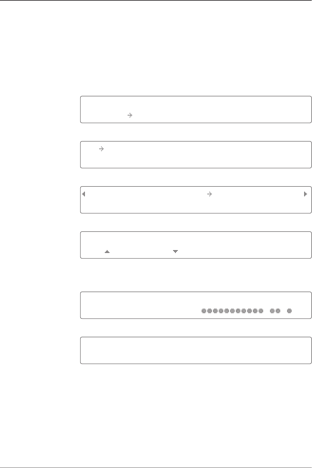
DIAGNOSTIC FULL TESTING
FULL TEST - -
5. A full diagnostic is successfully completed.
DIAGNOSTIC COMMUNICATION
CODE 101 RESULT : PASSED
6. A single diagnostic test is successfully completed.

v130 – Marine Satellite Communication System
64
Diagnosis Code:
CODE 101: The data communication between the antenna and the ACU is tested.
CODE 102: The azimuth motor is tested.
CODE 103: The elevation motor is tested.
CODE 104: The cross-level motor is tested.
CODE 105: The azimuth encoder is tested.
CODE 106: The cross-level encoder is tested.
CODE 107: The rate sensor is tested.
CODE 108: The tilt sensor is tested.
CODE 109: The sensor box motor is tested.
CODE 110: The LNB/NBD is tested.
CODE 111: The LNB pol motor is tested.
CODE 112: The sub-reector is tested. (Skip for v-Series communication products)
CODE 113: The antenna power is tested.
CODE 114: The ACU power is tested.
CODE 115: The receiver power is tested.
(Skip for v-Series communication products)
CODE 116: The home sensor is tested.
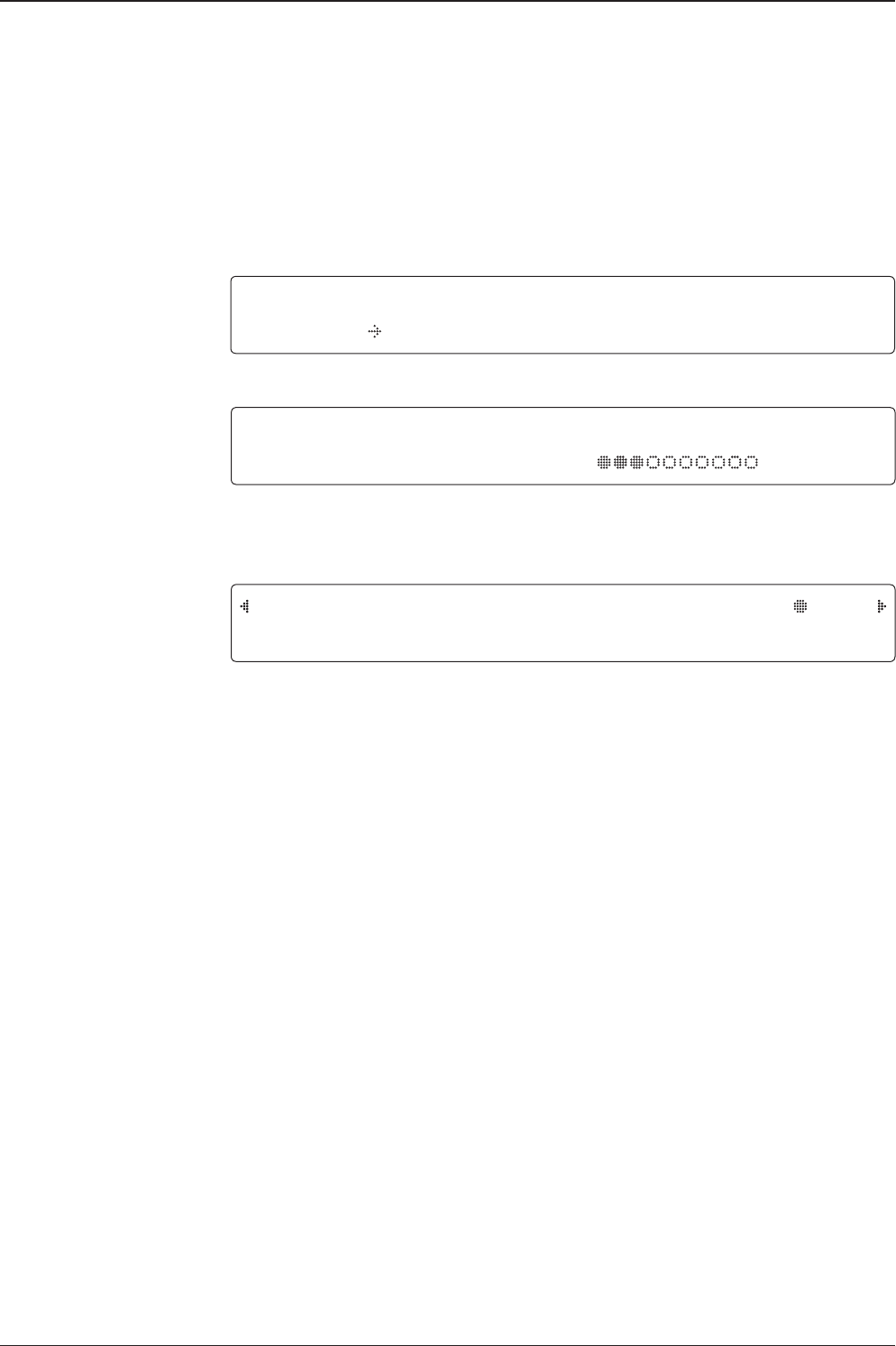
An example of test result: •2•••••••••-••-•
•: test is passed
2: test is failed (CODE102)
–: test is skipped (TVRO products only)
?: test is in process

65
OPERATING THE ACU
Satellite Settings
Load Satellite
Load
Load sat menu
Load satellite
Satellite menu
Setup mode SETUP MODE ?
YES NO
1. Press LEFT arrow key to move cursor to YES and press OK key to enter SETUP mode.
+ANTENNA +SATELLITE
+SYSTEM +INSTALLATION
2. Press RIGHT arrow key to move cursor to SATELLITE and press OK key to enter it.
+LOAD SAT. +EDIT SAT.
+ADD SAT. +CHECK NID
3. Press OK key to enter LOAD SAT. menu.
LOAD SATELLITE
[1] TELST_18 138.00E
4. Press UP and DOWN arrow keys to select satellite that you wish to track.
Press OK key to load the selected satellite.
LOAD ?
YES NO
5. Press LEFT arrow key to move cursor to YES and press OK key to load the selected
satellite and execute the current settings. Or press RIGHT arrow key to move cursor to NO
and press OK key to abort and return to the main display.

v130 – Marine Satellite Communication System
66
Edit Satellite Information
Edit satellite
Edit longitude & name
Edit sat menu
Satellite menu
Setup mode SETUP MODE ?
YES NO
1. Press LEFT arrow key to move cursor to YES and press OK key to enter SETUP mode.
+ANTENNA +SATELLITE
+SYSTEM +INSTALLATION
2. Press RIGHT arrow key to move cursor to SATELLITE and press OK key to enter it.
+LOAD SAT. +EDIT SAT.
+ADD SAT. +CHECK NID
3. Press RIGHT arrow key and OK key to enter EDIT SAT. menu.
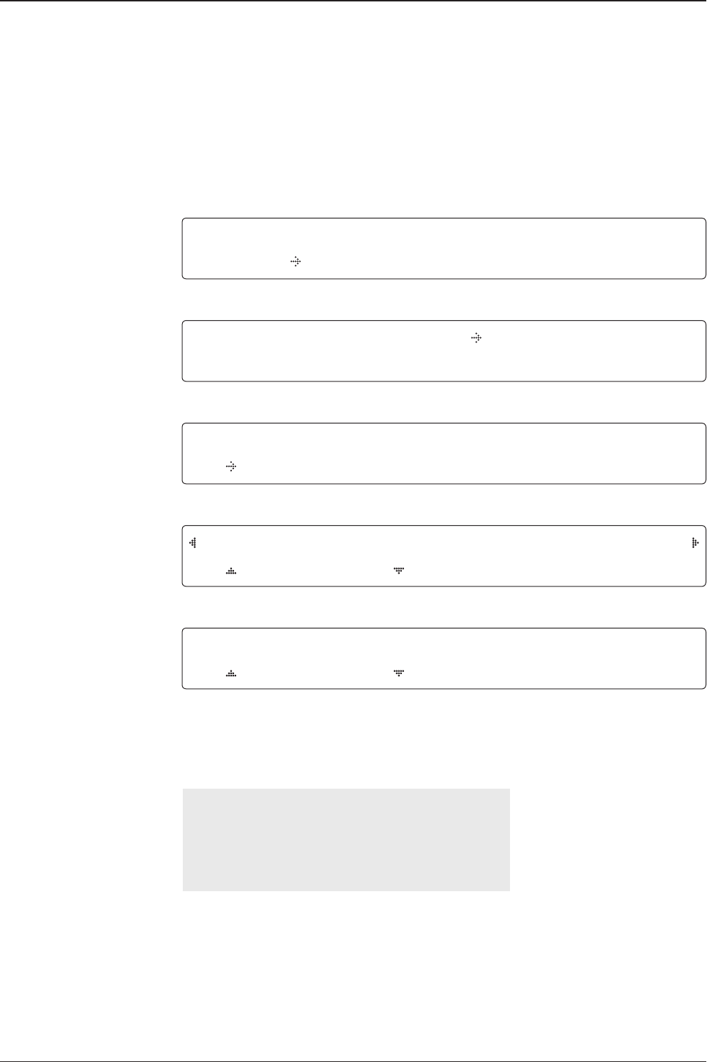
EDIT SATELLITE
[1] TELST_18 138.00E
4. Press UP and DOWN arrow keys to select the satellite that you wish to edit and press OK
key to edit the selected satellite.
LONGITUDE EDIT NAME
138.0E TELST_18
5. Edit satellite orbit position, LONGITUDE and satellite NAME.

67
OPERATING THE ACU
DVB VERIFY SKEW OFFSET
DVB DECODE +0.0
6. Edit satellite DVB VERIFY* method and SKEW OFFSET.
DVB VERIFY will be only activated and applied when DVB mode of TRACKING SIGNAL is
chosen to be used. Press UP and DOWN arrow keys to select DVB VERIFY and press OK
key to set the parameter.
DVB VERIFY*
AGC – use signal level for satellite tracking.
DVB Lock – use DVB Lock for satellite tracking.
DVB Decode – use DVB Decode for satellite tracking.
DSS Decode – use DSS Decode for satellite tracking.
SELECT LOCAL TRACKING SIGNAL
11300MHz NBD
7. Set SELECT LOCAL* frequency and TRACKING SIGNAL*.
Press LEFT and RIGHT arrow keys until the desired character is underscored (selected).
Press UP and DOWN arrow keys to increase or decrease the value.
Press OK key to set the parameter.
RX POL TX POL
VERT. HORI.
8. Set RX POL and TX POL
To select the polarity for both RX (receive ) and TX (transmit ).
Press UP and DOWN arrow keys to select VERTICAL or HORIZONTAL.
Press OK key to set the parameter.
DVB veriy method
Set polarity
Set LNB local frequency
TRACKING SIGNAL*
NBD
DVB
SELECT LOCAL*
The selectable LNB frequencies
are depended on the installed LNB
type.

v130 – Marine Satellite Communication System
68
Set NBD tracking
frequency
Save
Set DVB tracking
frequency DVB FREQ. SYMBOL NID
11747MHz 21300KSps 0X00AD
9. Set DVB FREQUENCY, SYMBOL RATE and NID when DVB mode of TRACKING SIGNAL
is chosen to be used.
45,000 is the maximum allowed symbol rate value. NID (network ID) range is from 0 x 0000
to 0 x FFFF (hexadecimal digit).
Press LEFT and RIGHT arrow keys until the desired character is underscored (selected).
Press UP and DOWN arrow keys to increase or decrease the value.
Or press NUMBER keys to set the desired value directly.
Press OK key to set the parameter.
NBD FREQ. BANDWIDTH
1070.000MHz 01.000MHz
10. Set NBD IF FREQUENCY and BANDWIDTH when NBD (Narrow Band Detection) mode of
TRACKING SIGNAL is chosen to be used.
Press LEFT and RIGHT arrow keys until the desired character is underscored (selected).
Press UP and DOWN arrow keys to increase or decrease the value.
Or press NUMBER keys to set the desired value directly. Press OK key to set the parameter.
SAVE ?
YES NO
11. Press LEFT arrow key to move cursor to YES and press OK key to save and execute the
current settings. Or press RIGHT arrow key to move cursor to NO and press OK key to abort
and return to the main display.
69
OPERATING THE ACU
Add Satellite Information
DVB verify method
Add sat menu
Set longitude & name
Setup mode
Satellite menu
SETUP MODE ?
YES NO
1. Press LEFT arrow key to move cursor to YES and press OK key to enter SETUP mode.
+ANTENNA +SATELLITE
+SYSTEM +INSTALLATION
2. Press RIGHT arrow key to move cursor to SATELLITE and press OK key to enter it.
+LOAD SAT. +EDIT SAT.
+ADD SAT. +CHECK NID
3. Press DOWN arrow key and OK key to enter ADD SAT. menu.
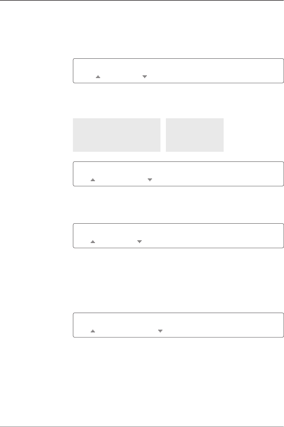
LONGITUDE EDIT NAME
000.00E SAT.00
4. Set satellite LONGITUDE and satellite NAME.
DVB VERIFY SKEW OFFSET
DVB DECODE +00.0
5. Edit the satellite DVB VERIFY* and SKEW OFFSET.
DVB VERIFY will be only activated and applied when DVB mode of TRACKING SIGNAL is
chosen to be used. Press UP and DOWN arrow keys to select DVB VERIFY and press OK
key to set the parameter.
DVB VERIFY*
AGC – use signal level for satellite tracking.
DVB Lock – use DVB Lock for satellite tracking.
DVB Decode – use DVB Decode for satellite tracking.
DSS Decode – use DSS Decode for satellite tracking.
v130 – Marine Satellite Communication System
70
Set LNB local frequency
Set polarity
Sat NBD tracking
frequency
Set DVB tracking
frequency
SELECT LOCAL TRACKING SIGNAL
10000MHz NBD
6. SELECT LOCAL* to set LNB local oscillator frequency and TRACKING SIGNAL*.
Press LEFT and RIGHT arrow keys until the desired character is underscored (selected).
Press UP and DOWN arrow keys to increase or decrease the value.
Press OK key to set the parameter.
TRACKING SIGNAL*
NBD
DVB
SELECT LOCAL*
The selectable LNB frequencies
are depended on the installed LNB
type.
RX POL TX POL
VERT. HORI.
7. Set RX POL and TX POL
To select the polarity for both RX (receive ) and TX (transmit ) pol.
Press UP and DOWN arrow keys to select VERTICAL or HORIZONTAL.
Press OK key to set the parameter.
DVB FREQ. SYMBOL NID
00000MHz 00000KSps 0X0000
8. Set DVB FREQUENCY, SYMBOL RATE and NID when DVB mode of TRACKING
SIGNAL is chosen to be used.
45,000 is the maximum allowed symbol rate value. NID (network ID) range is from 0 x 0000
to 0 x FFFF (hexadecimal digit).
Press LEFT and RIGHT arrow keys until the desired character is underscored (selected).
Press UP and DOWN arrow keys to increase or decrease the value.
Or press NUMBER keys to set the desired value directly.
Press OK key to set the parameter.
NBD FREQ. BANDWIDTH
0000.000MHz 01.000MHz
9. Set NBD IF FREQUENCY and detection BANDWIDTH when NBD (Narrow band detection)
mode of TRACKING SIGNAL is chosen to be used.
Press LEFT and RIGHT arrow keys until the desired character is underscored (selected).
Press UP and DOWN arrow keys to increase or decrease the value.
Or press NUMBER keys to set the desired value directly. Press OK key to set the parameter.

71
OPERATING THE ACU
Save
Check NID
NID verication
Check NID menu
Setup mode
Satellite menu
SETUP MODE ?
YES NO
1. Press LEFT arrow key to move cursor to YES and press OK key to enter SETUP mode.
+ANTENNA +SATELLITE
+SYSTEM +INSTALLATION
2. Press RIGHT arrow key to move cursor to SATELLITE menu and press OK key to enter it.
+LOAD SAT. +EDIT SAT.
+ADD SAT. +CHECK NID
3. Press DOWN arrow key and OK key to enter CHECK NID menu.
[CHECK NID] F:12490 S:27490 0X00AD
PRESS OK RECEIVED NID[0X0000]
4. CHECK NID is to verify the NID (Network ID) of the current tracking transponder.
Press OK key to verify the NID [0 x 0000] only when “ PRESS OK” function is activated.
“PRESS OK” function will only be activated when DVB Lock signal is conrmed by the
antenna. However, “NO LOCK” message will be displayed if DVB Lock signal can’t be
conrmed.
SAVE ?
YES NO
10. Press LEFT arrow key to move cursor to YES and press OK key to save and execute the
current settings. Or press RIGHT arrow key to move cursor to NO and press OK key to abort
and return to the main display.
v130 – Marine Satellite Communication System
72
Set LNB Local Oscillator Frequency
System Settings
System menu
Set local frequency menu
LNB info
Setup mode
Save
SETUP MODE ?
YES NO
1. Press LEFT arrow key to move cursor to YES and press OK key to enter SETUP mode.
+ANTENNA +SATELLITE
+SYSTEM +INSTALLATION
2. Press DOWN arrow key to move cursor to SYSTEM and press OK key to enter it.
+SET LOCAL +SET LOCATION
+MODEM PORT +MANAGEMENT
3. Press OK key to enter SET LOCAL menu to set the LNB local frequency.
13V + 0kHz 18V + 0kHz
10000MHz 11300MHz
13V + 22kHz 18V + 22kHz
10750MHz 09750MHz
4. Set LNB local oscillator frequency for each correspondent voltage power.
(13V +0 kHz, 18V +0 kHz, 13V +22 kHz, 18V +22 kHz)
Press BACK key and press LEFT and RIGHT arrow keys to select the parameter you wish to
edit. Press OK key to edit parameter. Or press BACK key again to return to the main display.
SAVE ?
YES NO
5. Press LEFT arrow key to move cursor to YES and press OK key to save current settings.
Or move cursor to NO and press OK key to abort and return to the main display.
73
OPERATING THE ACU
Set Location
System menu
Set location menu
Gyro type and
Baud rate
Setup mode SETUP MODE ?
YES NO
1. Press LEFT arrow key to move cursor to YES and press OK key to enter SETUP mode.
+ANTENNA +SATELLITE
+SYSTEM +INSTALLATION
2. Press DOWN arrow key to move cursor to SYSTEM and press OK key to enter it.
+SET LOCAL +SET LOCATION
+MODEM PORT +MANAGEMENT
3. Press RIGHT arrow key to move cursor to SET LOCATION and press OK key to enter it.
GYRO TYPE BAUD RATE
NMEA 4800
4. Set the ship’s GYRO TYPE* and BAUD RATE
A search pattern 1 or 3 will be initiated according to which GYRO TYPE is selected and the
existence of the gyro input. Set the BAUD RATE as 4800, 9600, 19200 or 38400 according
to your device.
A search pattern 1 will be initiated automatically if the gyro input does not exist and the gyro
type is selected other than GROUND TEST.
NOTE: The bow offset will not be saved automatically if Search 1 pattern is initiated. In this case, the
antenna will need to re target the desired satellite using Search 1 every time if the antenna restarts.
Gyro search type Setting of Heading Device
Existence of Heading Data No Device NMEA /
NMEA2000 Ground Test
With Heading Data Search 1 Search 3 Search 3
Without Heading Data Search 1 Search 1 Search 3
GYRO TYPE*
NO DEVICE
NMEA
NMEA2000
GROUND TEST

v130 – Marine Satellite Communication System
74
Heading
Latitude & longitude
Save
LATITUDE LONGITUDE
37.00N 126.50E
5. Set the current LATITUDE and LONGITUDE
Press LEFT and RIGHT arrow keys until the desired character is underscored (selected).
Press UP and DOWN arrow keys to increase or decrease the value.
Or press NUMBER keys to set the desired value directly.
Press the OK key to set the parameter.
HEADING
090.0
6. Entry of ship’s heading is not required when your system is connected to a NMEA(0813)
or NMEA2000.
Ensure that the supported Gyro Type is set correctly. If the ship's gyrocompass output is
other than NMEA0183 and NMEA2000, a purchase of an NMEA converter is required.
SAVE ?
YES NO
7. Press LEFT arrow key to move cursor to YES and press OK key to save current settings.
Or move cursor to NO and press OK key to abort and return to the main display.

75
OPERATING THE ACU
Set Modem Port
System menu
Modem port menu
Set Mediator &
modem type
Setup mode SETUP MODE ?
YES NO
1. Press LEFT arrow key to move cursor to YES and press OK key to enter SETUP mode.
+ANTENNA +SATELLITE
+SYSTEM +INSTALLATION
2. Press DOWN arrow key to move cursor to SYSTEM menu and press OK key to enter it.
+SET LOCAL +SET LOCATION
+MODEM PORT +MANAGEMENT
3. Press DOWN arrow keys to move cursor to COM. PORT menu and press OK key to enter
it.
USE MEDIATOR MODEM TYPE
YES I DIRECT-I/O
4. USE MEDIATOR is to enable the usage of MEDIATOR if the antenna is connected to the
Intellian Dual VSAT Mediator.
NOTE: USE MEDIATOR must be disabled if there is no MEDIATOR connected to the ACU. Improper
setting of this parameter will cause your ACU’s modem interface working incorrectly.
MODEM TYPE* is to select a proper data communication port and protocol on the ACU to
interface with the satellite modem. The settings related to the modem interface will be set
automatically once the modem type is selected. Select "USER SETTING" if a desired modem
type is not available in the option.
The options on the next page will be displayed and required to be set if "USER SETTING" is
selected.
MODEM TYPE*
• USER SETTING
• IDIRECT-I/O
• IDIRECT-AMIP
• COMTECH-I/O
• COMTECH-ROSS
• HUGHES
• SATLINK-SERIAL
• SATLINK-VACP
• ELEKTRIKOM-AMIP
• GILAT-SE-II

v130 – Marine Satellite Communication System
76
M ODEM PORT PROTOC OL
ETHERNET I /O CONSOLE
5. MODEM PORT* is to select a proper data communication port on the ACU to interface
with the modem.
PROTOCOL*
I/O CONSOLE: is a protocol for interchanging of information (GPS Out, TX mute, and
modem lock) between the ACU (through Console port) and a modem.
OPEN AMIP: is an ASCII based protocol developed by iDirect for interchanging of
information between the ACU and a modem. OpenAMIP is not intended for any purpose
except to allow the ACU and a modem to perform synchronized automatic beam
switching (ABS).
SERIAL GPS: is a protocol for sending GPS Out information from the ACU (through
RS232/422 port) to a modem.
ROSS: ROSS Open Antenna Management (ROAM) protocol is developed by Comtech
EF Data Cooperation to offer common management interface for Comtech EF Data's
Roaming Oceanic Satellite Server (ROSS) and ACU.
VACP: is the interface between the SatLink mobile VSAT IDU and the Intellian antenna
controllers for Intellian mobile antennas.
ELEKTRIKOM-AMIP: is the interface using extended OpenAmip including the console
port (modem lock) between the electrikom ROAM-PC and the Intellian controller.
GILAT-SE-II: is a protocol that generates between the Gilat SkyEdge modem and the
Intellian antenna controllers two-channel interfacing based on the NMEA 0183 data
protocol. The interfacing occurs via RS232 serial port at 9600-N-8-1 baud.
6. GPS OUT SENTENCE* is to select the GPS OUT SENTENCE type USE TX MUTE is
to select whether or not to USE TX MUTE function from the satellite modem. A transmit
inhibit output from the ACU will disable/mute the modem transmit via a voltage whenever the
antenna is blocked, searching, or is mis-pointed 0.5 degrees from the peak satellite position.
Set modem protocol
Use TX mute
G PS O UT SENTE NCE USE TX MUTE
GPGLL YES
GPS OUT SENTENCE*
GPGLL
GPGGA
SIMPLE GPGGA
MODEM PORT*
ETHERNET
RS422
RS232
PROTOCOL* is to select a proper communication protocol on the ACU to
interface with the modem.

77
OPERATING THE ACU
TX mute activation
Save
TX MUTE ACTIVE
LOW
7. TX MUTE ACTIVE is a transmit inhibit output from the ACU to disable/mute the modem
transmit through a 5 V (HIGH) or 0 V (LOW) current whenever the antenna is blocked,
searching, or is mis-pointed 0.5º from peak satellite position. TX MUTE ACTIVE item will only be
activated when PROTOCOL is set as I/O CONSOLE.
SAVE ?
YES NO
Use EXT.LOCK USE EXT.LOCK EXT. LOCK ACTIVE
YES LOW
6. USE EXT. LOCK is to select whether or not to use external lock signal from the satellite
modem. USE EXT. LOCK item will only be activated when PROTOCOL is set as I/O CONSOLE.
EXT. LOCK ACTIVE is referred that modem lock output from the modem provides a logic input
through a 5 V (HIGH) or 0 V (LOW). current to the ACU to identify when it is on the correct
satellite. EXT. LOCK ACTIVE item will only be activated when PROTOCOL is set as I/O CONSOLE.
8. Press LEFT arrow key to move cursor to YES and press OK key to save current settings.
Or move cursor to NO and press OK key to abort and return to the main display.
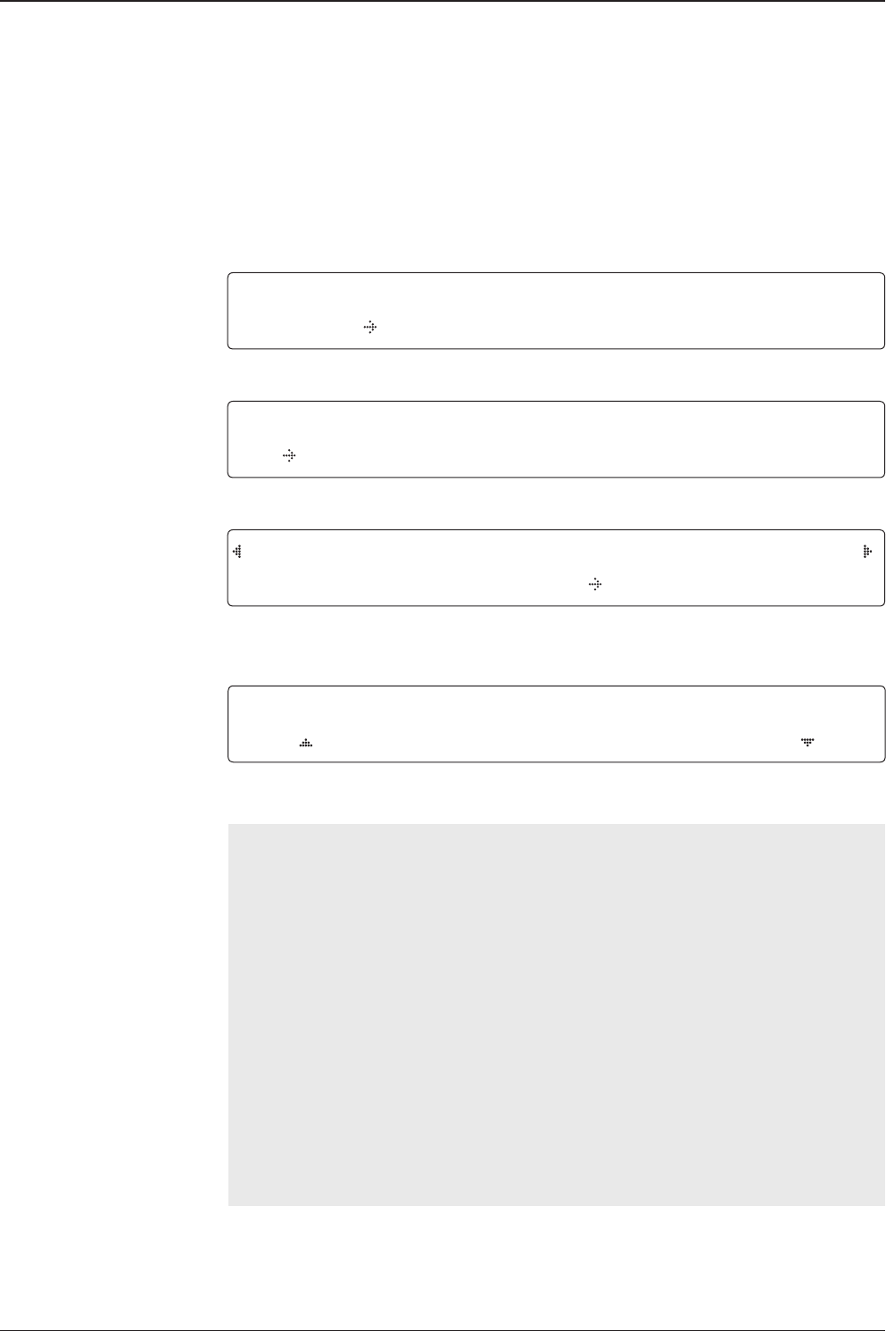
v130 – Marine Satellite Communication System
78
SELECT PROCESS TYPE
BACKUP USER DATA
4. Press UP and DOWN arrow keys to SELECT PROCESS TYPE*
Press OK key to set the parameter and the processing message will be displayed.
SELECT PROCESS TYPE*
BACKUP USER DATA: To backup the antenna settings set by user to the ACU.
RESTORE USER DATA: To restore the antenna by using the backup user data stored
from the ACU.
DEFAULT ACU-REMOTE P/W: To change the web server module's password to default.
UPGRADE FROM USB: To upgrade the system by using rmware les (FWP)
from a specied folder in a USB ash drive.
COPY LOG TO USB: to copy the antenna log data from the system to a USB ash drive.
BACKUP TO USB: To backup the antenna settings set by user to a USB ash drive.
RESTORE FROM USB: To restore the antenna by using the backup user data from a
USB ash drive.
UPGRADE ACU-REMOTE: To upgrade the system using rmware les (FWP) from a
specied folder in a USB ash drive.
NOTE: UPGRADE FROM USB, COPY LOG TO USB, BACKUP TO USB, RESTORE
FROM USB and UPGRADE ACU-REMOTE options are displayed only if the USB ash
drive is plugged into the USB port.
System Management
System menu
Backup and restore
menu
Setup mode SETUP MODE ?
YES NO
1. Press LEFT arrow key to move cursor to YES and press OK key to enter SETUP mode.
+ANTENNA +SATELLITE
+SYSTEM +INSTALLATION
2. Press DOWN arrow key to move cursor to SYSTEM menu and press OK key to enter it.
+SET LOCAL +SET LOCATION
+MODEM PORT +MANAGEMENT
3. Press arrow keys to move cursor to MANAGEMENT menu and press OK key to enter it.
Select process type
Processing
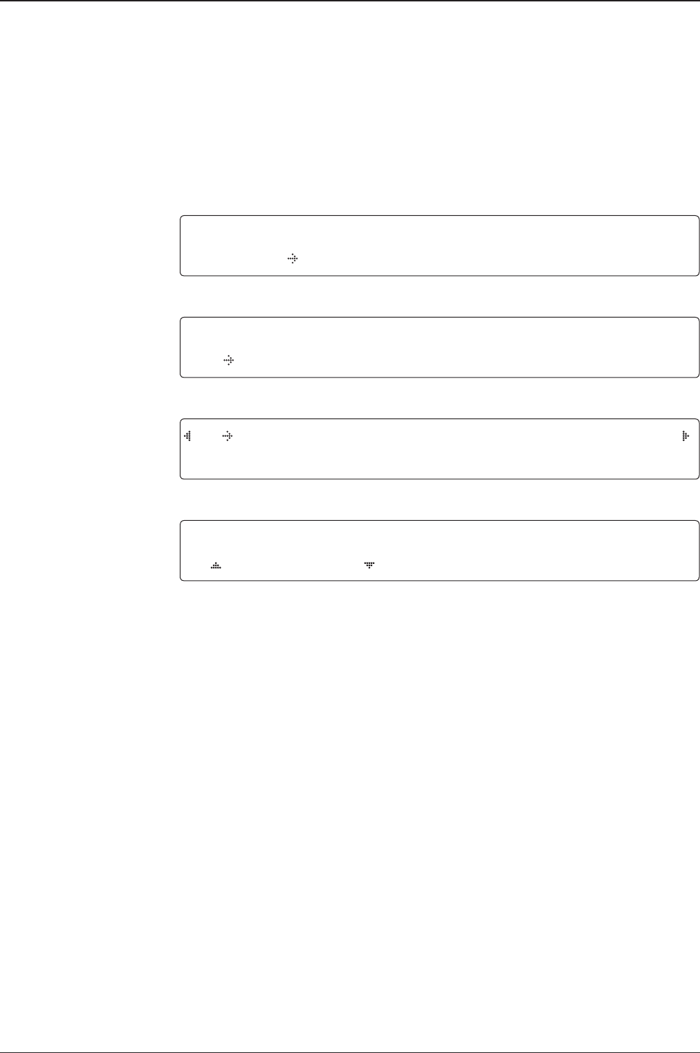
79
OPERATING THE ACU
System menu
Set key lock and
password
Key lock menu
Setup mode SETUP MODE ?
YES NO
1. Press LEFT arrow key to move cursor to YES and press OK key to enter SETUP mode.
+ANTENNA +SATELLITE
+SYSTEM +INSTALLATION
2. Press DOWN arrow key to move cursor to SYSTEM menu and press OK key to enter it.
+KEY LOCK +INTELLIAN DEVICE
3. Press arrow keys to move cursor to KEY LOCK menu and press OK key to enter it.
KEY LOCK UNLOCK P/W
ON 1590
4. Press UP and DOWN arrow keys to choose whether or not to use key pad lock when
entering the SETUP mode or saving the satellite information. Setup the password for entering
the key pad lock. The factory default is 1590.

v130 – Marine Satellite Communication System
80
ANTENNA CONTROL
SOFTWARE
Introduction to Aptus®
Requirements
Software Installation
PC to ACU Communication Setup
Starting Aptus®
Establishing a data communication
Toolbar Menus
System Property Status Dashboard
Work View Tabs
Antenna - Basic Info.
Antenna - Advanced Info.
Satellite
Graph View
Monitor
Diagnostic/Modem
GUI
Work View Functions

81
PC CONTROLLER SOFTWARE
Intellian’s Antenna PC Controller Software, Aptus® is a next-generation graphically
based antenna remote control software. The Aptus® allows users to easily and
conveniently set up the antenna by using a personal computer.
The minimum PC hardware and software requirements to install and run Aptus® are
as below.
Hardware
Hardware Requirements
CPU Intel® Pentium® 4 or higher
Memory 512MB or higher
Video Card
DirectX9.0 or higher supported
H/W acceleration supported
Video Memory 128MB or higher
HDD 1GB or higher
Operating System and Software
Software Requirements
Operating System Windows XP SP or higher
Framework Microsoft.Net Framework 3.5 Service Pack 1 or higher
Introduction to Aptus®
Requirements
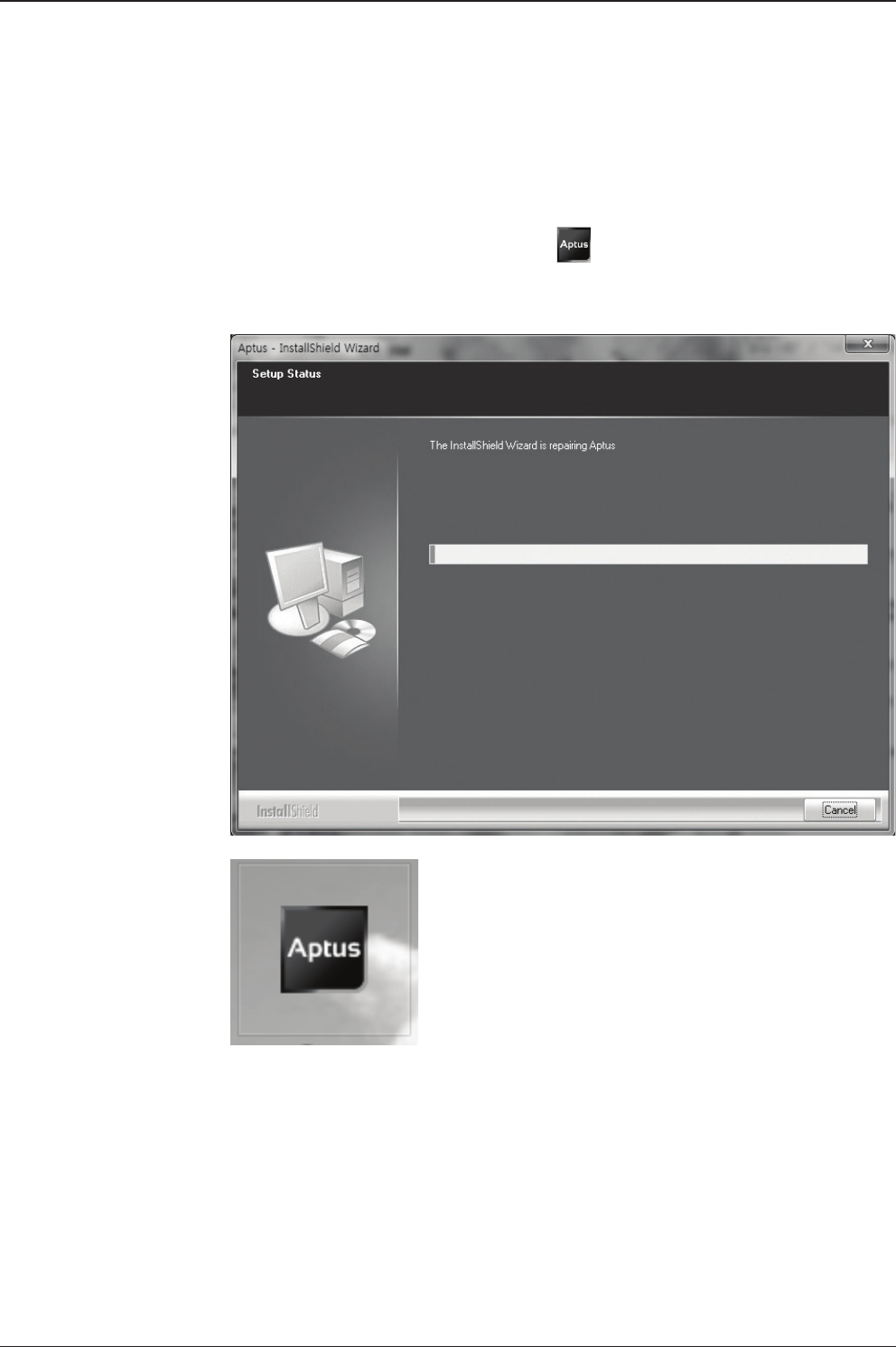
v130 – Marine Satellite Communication System
82
Software Installation
Double click the ‘Aptus Setup.exe’ icon to install Aptus® directly onto your
computer/ laptop. The InstallShield Wizard will guide you through the program
setup process. The installation routine provides an icon on the desktop.
Click the icon to start the software. In addition, Intellian also provides patch les
for software upgrade.
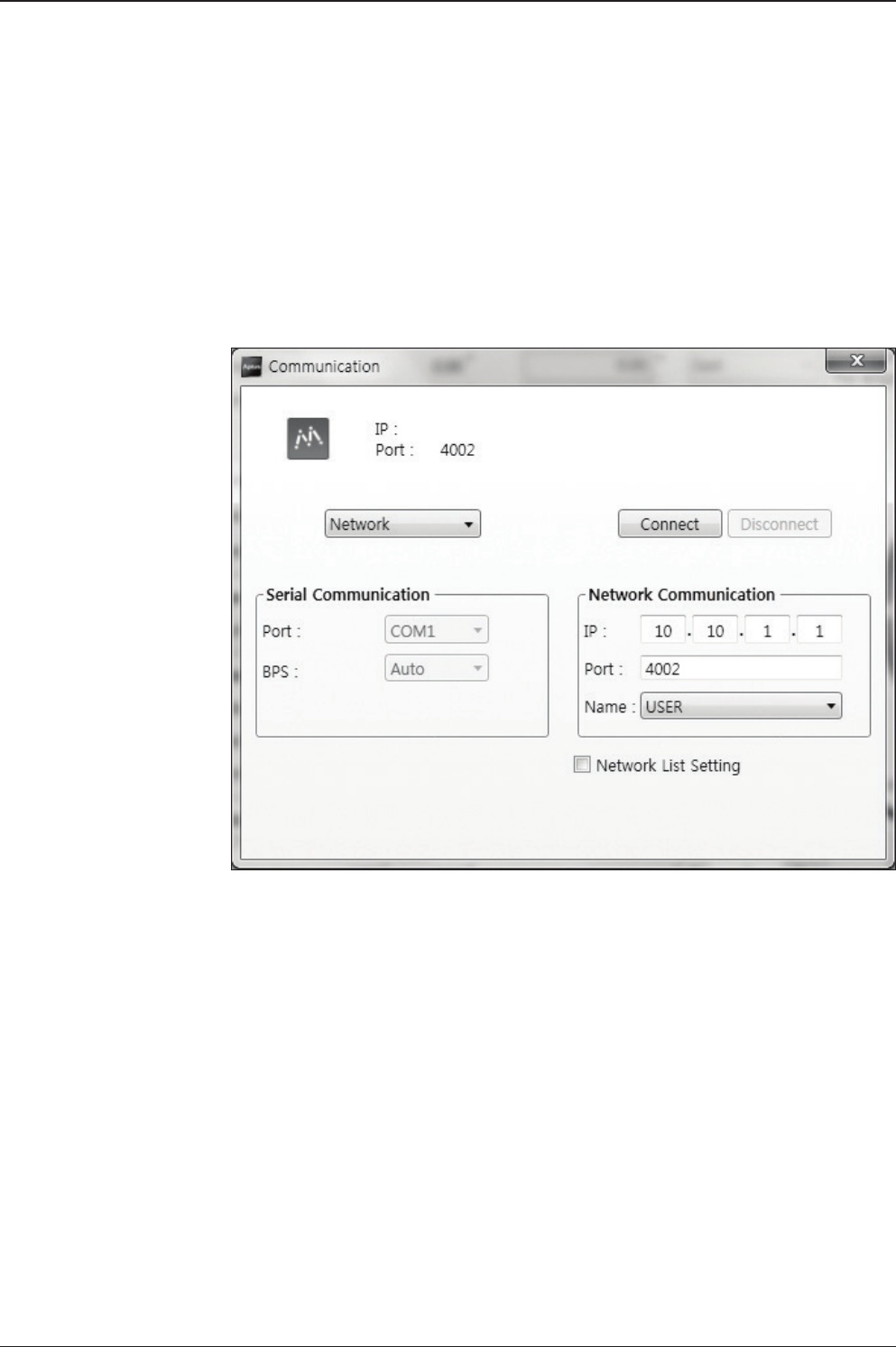
83
PC CONTROLLER SOFTWARE
PC to ACU Communication Setup
Starting Aptus®
Double-click the Aptus® desktop icon, then Communication Window appears
to establish the data communication between your PC and the ACU. Select
options of connection method to access your ACU either through the Serial Port
Communication or the Network Communication (TCP/IP).
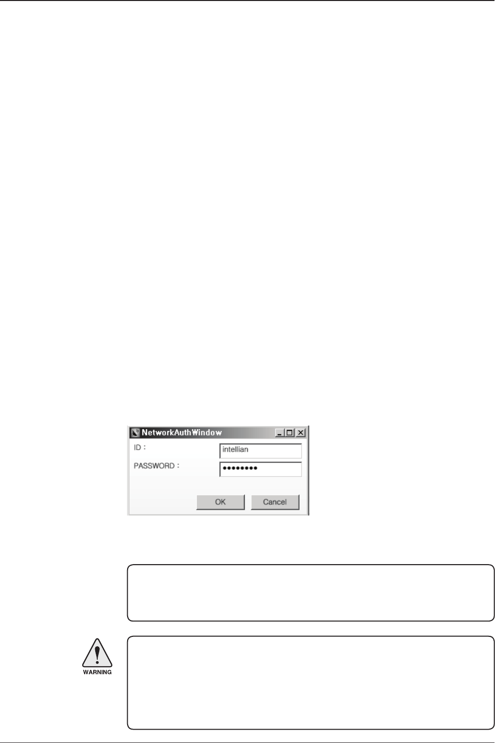
v130 – Marine Satellite Communication System
84
Establish a data
communication
Access ACU through Serial Communication
1. Connect a 9 pin Serial cable between the PC INTERFACE connector on
the ACU and the 9 pin Serial port on the PC. (Or you can use a USB cable
to setup Serial connection between a PC and the USB port on the ACU.)
2. Select Serial at communication type combo-box.
3. The baud rate of the ACU is 19200.
4. Select a COM port which is not occupied by other devices.
5. Click the Connect button.
Access ACU through Network Communication (TCP/IP)
1. Turn off the wireless connection while using this method.
2. Connect your PC to the Management Port.
3. Select Network at communication type combo-box.
4. Enter in the ACU’s IP address (Factory default : 192.168.2.1)
5. Enter in the ACU’s port number (Factory default : 4002)
- Enter 4003 for SSL Secure Connection.
6. Click the Connect button then the Authentication window will appear.
7. Login by using the username and password below:
- Username: intellian (Factory default)
- Password: 12345678 (Factory default)
WARNING:
- Do not plug a USB to the ACU while TCP/IP communication is in use.
Doing so will disable current PC Software Control because the USB
connection has higher priority than TCP/IP connection.
- The amount of data will increase rapidly if Network Communication is in use.
Intellian recommends using Aptus Web.
NOTE: If the remote access PC is located in the same network group with the ACU,
the ACU can be accessed through the internal IP address. But, if the remote access
PC is located outside of the network group, the ACU’s IP address should be changed
to the IP address assigned by the network service provider.
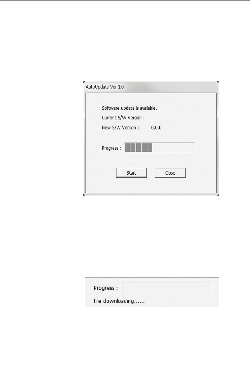
85
PC CONTROLLER SOFTWARE
AutoUpdate
Intellian Aptus® checks and noties the latest version when it is started to maintain
up to date software version by AutoUpdate function.
1. When Aptus® is started, it automatically checks the latest software version from
the server and runs AutoUpdate if new version is available.
2. Current software version information is displayed.
3. It noties new software version information.
4. When you click the “start” button, “File downloading…” message is displayed
while downloading les from the server.
5. When le downloading is nished, “installing…” message is displayed and Aptus
patch runs and the installation starts by InstallShield.
6.Click the “Finish” button when InstallShield installation is nished, then “Run
the Aptus” message is displayed and Aptus runs and AutoUpdate is automatically
nished.
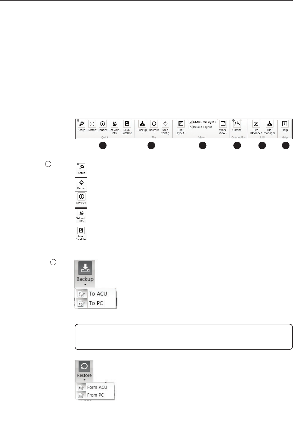
v130 – Marine Satellite Communication System
86
Quick
File
Toolbar Menus
The toolbar menus at the top of the screen display command buttons of the most
commonly used functions of the Aptus®. The toolbar menus consists of 4 main
menus; Quick (for quick launch of functions), File (for le backup, restoring and
loading), View and Connection.
Setup: enters Setup mode.
Restart: exits Setup mode and restarts the antenna.
Reboot: reboots the antenna.
Get Ant. Info: obtains the information stored in the antenna
Save Satellite: saves the current bow offset only if the antenna is tracking
onto the satellite. The satellite acquisition time can be reduced signicantly
after the antenna is restarted.
1
2Backup: backups the antenna information to ACU or PC.
- Select ‘To ACU’ to backup the antenna information to ACU.
The backup le (le format: *.ibf) will be stored on the ACU.
- Select ‘To PC’ to backup the antenna information to a PC.
The backup les (le format: *.rpt and *.ibf) will be generated
on the PC.
Restore: restores the antenna by using the stored information in
ACU or PC.
- Select ‘From ACU’ to restore the antenna by using the stored
information in ACU.
- Select ‘From PC’ to restore the antenna by using the stored
information in PC (le format: *.ibf).
NOTE: Both *.rpt and *.ibf les contain antenna information. However, while *.ibf le can
be used for restoring antenna information, *.rpt le is stored as plain-text for viewing
purpose only. Users can open the *.rpt using text editors such as notepad software.
123 4 5 6
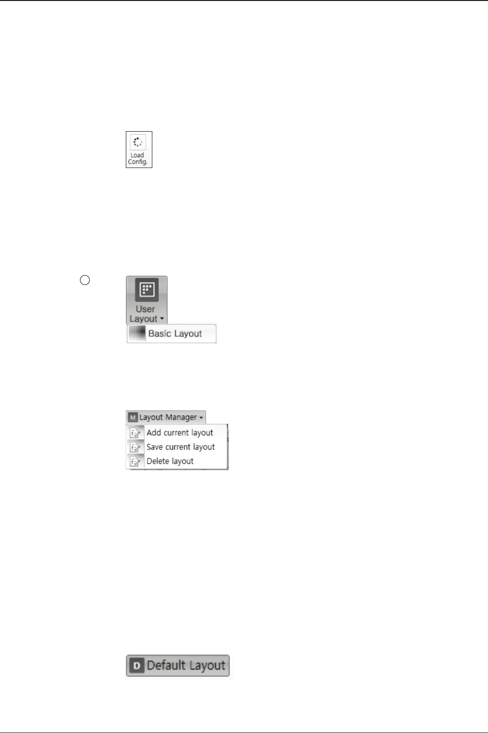
87
PC CONTROLLER SOFTWARE
NOTE: Both *.rpt and *.ibf les contain antenna information. However, while *.ibf le can
be used for restoring antenna information, *.rpt le is stored as plain-text for viewing
purpose only. Users can open the *.rpt using text editors such as notepad software.
View
3
• User Layout: displays the layout list that the user has previously stored by using
Layout Manager. If you select a layout in this list, the selected layout will be
constructed in Work View screen. The ‘Basic layout’ is provided by default.
• Layout Manager: provides the user with add, delete, and save functionalities in
order to manage the user’s layouts.
- Selecting ‘Add current layout’ opens a pop up window. Type in a desired name
of current layout and click Add, then the new name of the current layout will be
saved to the list under User Layout menu.
- When changes are made to the current layout, select ‘Save current layout’ option.
The current layout will be saved with changes.
- To remove a layout, select ‘Delete layout’ option. Select a desired layout to remove
on the pop up window, then click ‘Delete’. Close the window by clicking on ‘Close’.
The selected layout is removed from the User Layout list.
• Default Layout: returns the current layout to the default layout.
Load Cong. : loads the antenna conguration le (le format: *.cfg).
The conguration le includes the antenna control parameters which are
pre-loaded at the factory and should only be changed by an authorized service
technician. Improper setting of these parameters will cause your system to
perform improperly.
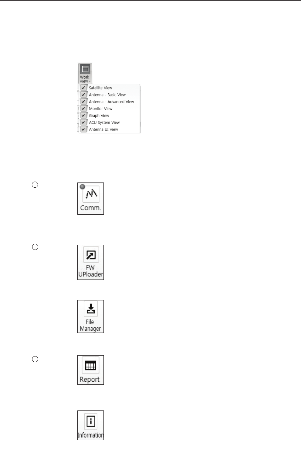
v130 – Marine Satellite Communication System
88
Connection
4
• Work View: displays a list of seven pre-constructed Work View Tabs (Satellite
View, Antenna Basic View, Antenna Advanced View, Monitor View, Graph View,
ACU System View, and Antenna UI View) and also provides the Activate / Close
functionalities for each view tab. Activate the work view tab by ticking the
checkbox next to it.
At any time, data communication channel can be re-established between Serial
and Network connection. Selecting Comm. Button will display Communication W
indow to connect to the ACU via Serial or Network communication.
Utill
5
Help
6
• Firmware Uploader: provides the user with the latest rmware version and
updates rmware by simple steps.
• File Manager: display the latest rmware and library le available on Aptus Server.
Select a desired rmware and download to the local PC.
• Report: provides e-mail contact to Intellian technical support team to let the user
report problems at any time.
• Information: displays the information of current Aptus® software version.
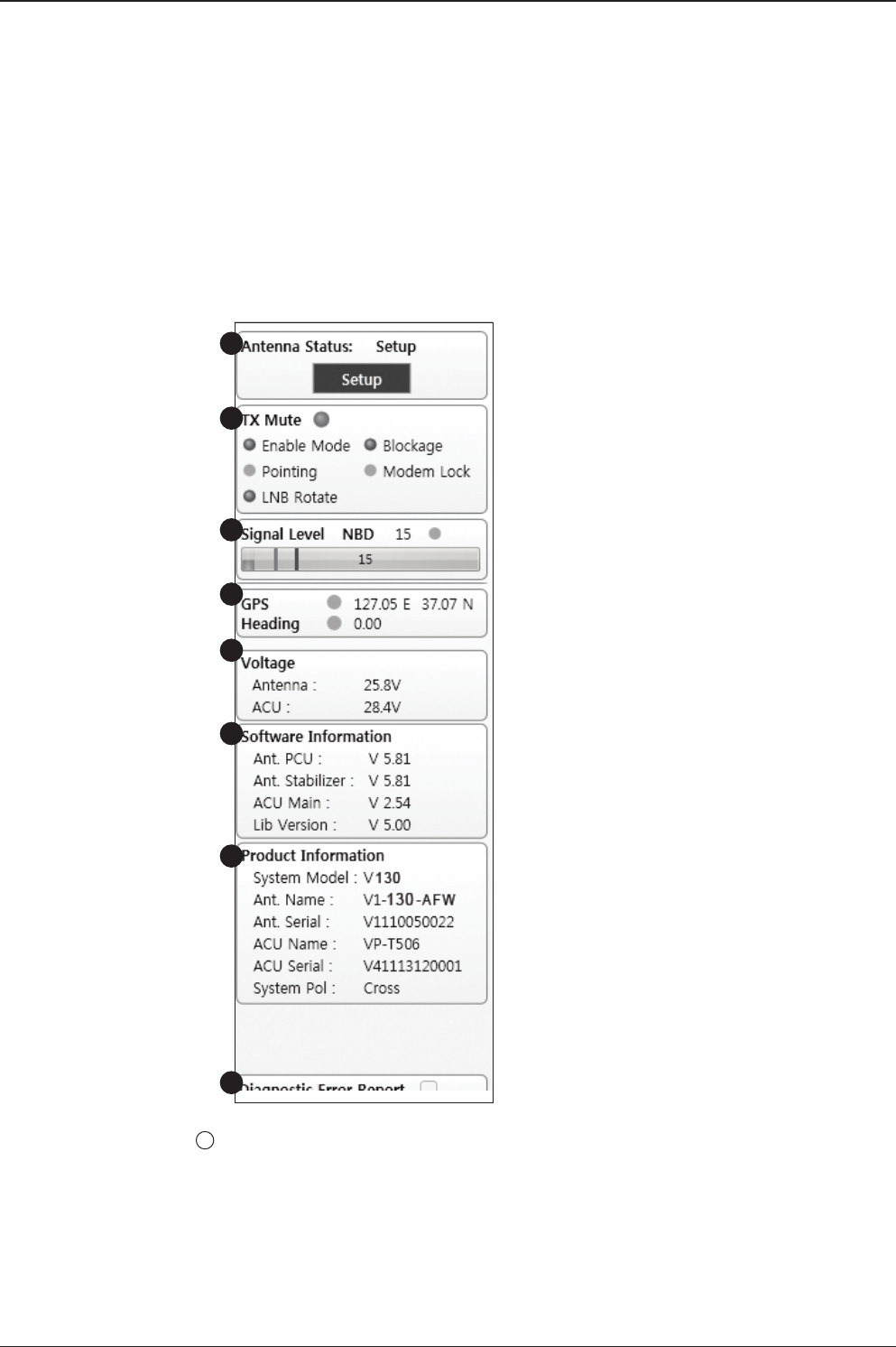
89
PC CONTROLLER SOFTWARE
System Property Status Dashboard
The property status dashboard on the left pane of the screen provides the antenna
status, the availability of TX transmission, signal level, GPS and heading status,
software information, product information and error status to be monitored quickly.
Antenna Status: Displays the status of the current mode of the antenna.
- Search 1: A Search 1 pattern will automatically be initiated when the ship’s
heading input does not exist or if it fails. The search cycle will repeat until the
antenna receives the lock signal from the modem or until the DVB transponder
of the target satellite is decoded by the antenna.
- Search 2: Search 2 is reserved for future use.
1
1
2
3
4
5
6
7
8

v130 – Marine Satellite Communication System
90
- Search 3: Search 3 pattern will automatically be initiated when AGC(DVB mode
is in use) or SIG/dB (NBD mode is in use) falls below the current tracking level
threshold value. Once the desired signal is found and above the predened
tracking threshold, the ACU will enter to tracking mode.
- Tracking: Antenna is tracking the target satellite.
- Initialize: Antenna or ACU is initializing.
- Setup: Antenna is in SETUP mode.
TX Mute
Displays the status of TX transmit. If the circle next to the TX Mute shows “Blue”,
it means the antenna TX function is enabled. If the circle shows “Red”, it means
the antenna TX function is disabled. The TX function will be enabled only if all ve
factors (Enable Mode, Blockage, Pointing, Modem Lock, and LNB Rotate) listed
below show a “Blue” circle. However, if the “Use TX Mute” function in the ‘ACU
System’ Work Tab is disabled, the TX function will be enabled regardless the above
factors.
- Enable Mode: displays whether or not the antenna is in SETUP mode. If the
antenna is in Setup mode, the circle next to the Enable Mode will show “Gray”.
- Blockage: displays whether or not the antenna is pointing in a predened block
zone(s). If the antenna is pointing in the block zone, the circle next to the Blockage
will show “Gray”. If the antenna pointed outside the block zone, the circle next to
the Blockage will show “Blue”.
- Pointing: displays whether or not the antenna is pointing to the target satellite. If
the antenna is mis-pointing to the target satellite, the circle next to the Pointing will
show “Gray”. If the antenna is pointing to the target satellite, the circle next to the
Pointing will show “Blue”.
- Modem Lock: displays whether or not the modem is locked by receiving a
conrmation signal from the satellite modem. If the modem is not locked, the circle
next to the Modem Lock will show “Gray”. If the modem is locked, the circle next to
the Modem Lock will show “Blue”.
NOTE: If the Modem Lock shows “Gray”, check the cable connection between
the antenna system and the satellite modem as well as settings on the modem.
- LNB Rotate: displays whether or not the LNB is rotating. If the LNB is rotating, the
circle next to the LNB Rotate will show “Gray”. If the LNB is not rotating, the circle
next to the LNB Rotate will show “Blue”.
2
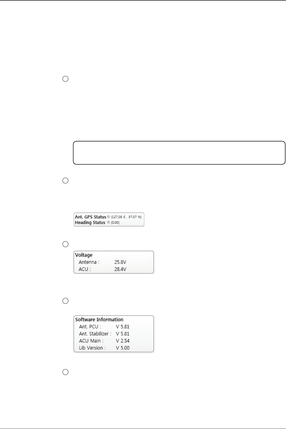
91
PC CONTROLLER SOFTWARE
Signal Level
Shows “DVB” when DVB mode of tracking signal is in use and “NBD” when NBD
mode of tracking signal is in use. The “Red” line indicates the signal “Detect Level
Threshold” and the “Orange” line indicates the signal “Tracking Level Threshold”.
If the signal level is higher than the tracking level threshold, the signal level bar will
display “Blue” color. If the signal level is lower than the tracking level threshold, the
signal level bar will display “Orange” color and the antenna will stay in searching
mode.
NOTE: If the signal level is not higher than the tracking threshold, decrease the detect
and tracking level.
GPS and Heading
Displays the current GPS location from the Antenna and Ship’s heading information.
The status light ashes green if the system receives a correct input of the GPS and
Ship’s heading.
Voltage: Displays the antenna and the ACU voltage information.
Software Information: Displays the antenna and the ACU rmware versions, and the
library version.
Product Information: Displays the antenna and ACU serial numbers, antenna model
and ACU model.
3
4
5
6
7
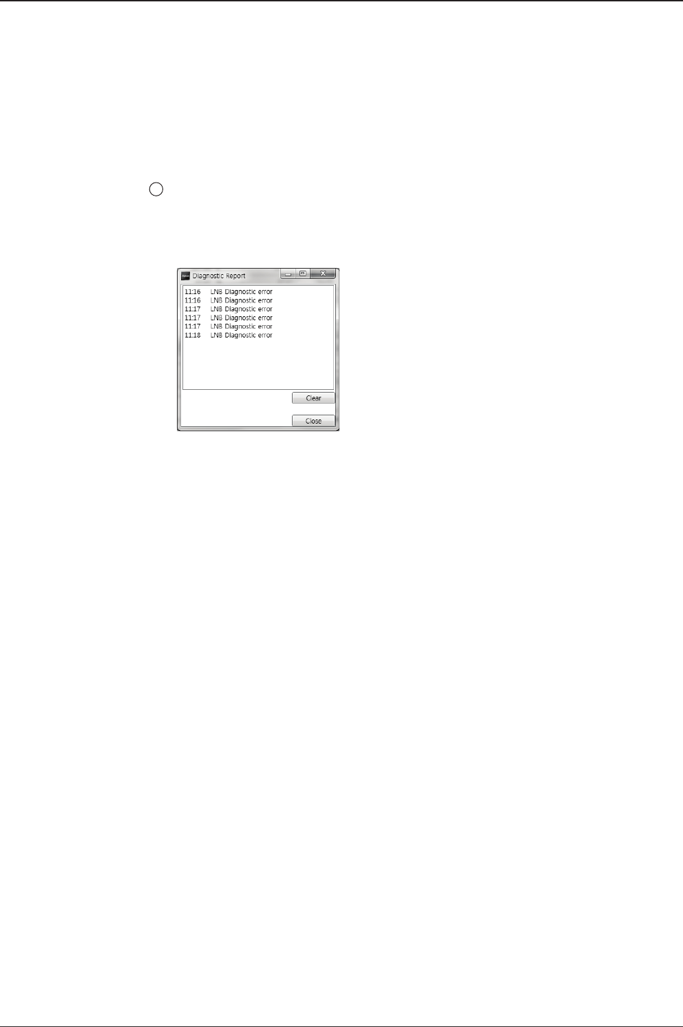
v130 – Marine Satellite Communication System
92
Diagnostic Error Report
The square button next to the Diagnostic Error Report turns red when the system
receives an error. Click the button to see a Diagnostic Report.
8
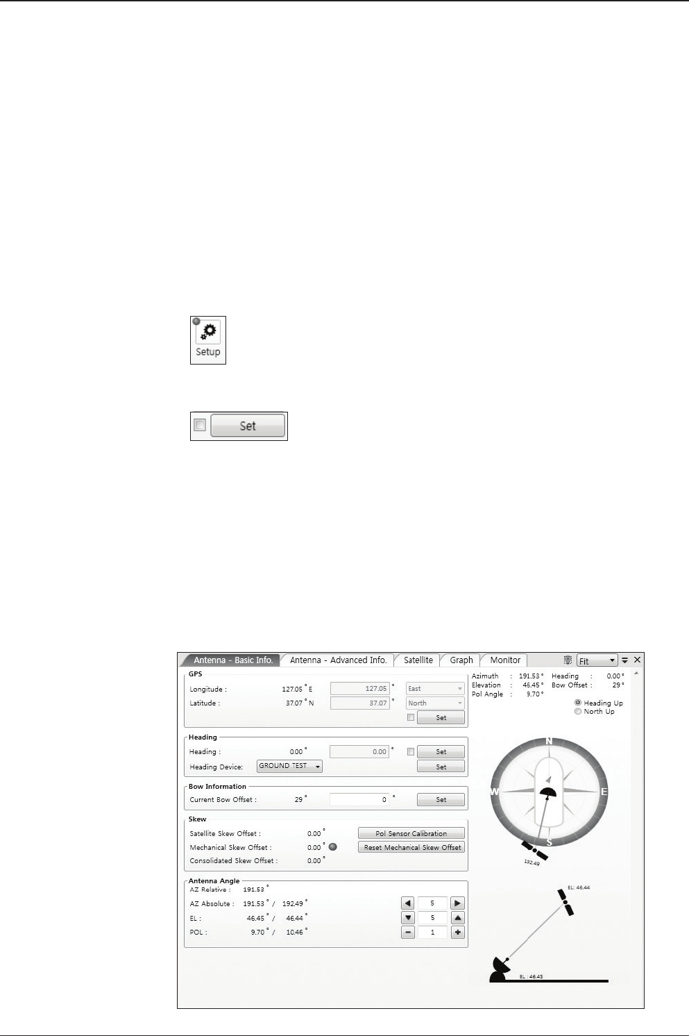
93
PC CONTROLLER SOFTWARE
Aptus® provides seven Work View Tabs (Satellite View, Antenna Basic View,
Antenna Advanced View, Monitor View, Graph View, ACU System View, and An-
tenna UI View) to manage the Antenna and the Satellite conguration.
How to modify the settings on Work View;
1. Enter the Setup mode by clicking Setup icon.
2. Tick the checkbox next to the “Set” button to modify the settings.
3. Enter the desired value then press the Set button to save the settings.
1. Antenna – Basic Info.
This view tab provides information on the Antenna’s Current GPS location, Head-
ing Device, Bow Information, Skew Information, and the Antenna’s Angle. This
view tab uses the Antenna’s AZ and EL information as well as the Ship’s Heading
information in order to provide a dynamic graphic user interface (UI).
Work View Tabs

v130 – Marine Satellite Communication System
94
- GPS: displays and sets current antenna’s GPS.
- Heading: displays and sets current ship’s heading information.
· Heading Device: None / NMEA/ NMEA 2000/Ground Test.
The baud rate (4800/ 9600/ 19200/ 38400) must be set if NMEA is selected.
- Bow Information: displays and sets current antenna’s bow.
- Skew: displays current antenna’s skew and skew offset.
· Pol Sensor Calibration: calibrates the sensor (potentiometer).
· Reset Mechanical Skew Offset: the mechanical skew offset is preset in the
factory with a default value (0, 1, or 2) depending on the assembly status.
Resetting of the mechanical skew offset may be required when the satellite
skew offset is unknown (Consolidated Skew Offset = satellite skew offset
+ mechanical skew offset). Due to each satellite has its own skew offset,
Intellian recommends you check with your service provider or satellite
operator to get the satellite skew offset value and input it in Satellite Work
Tab rather than resetting the mechanical skew offset directly.
- Antenna Angle: displays and sets current antenna’s absolute and relative AZ
(azimuth) position, EL (elevation) position and LNB Pol angle. You can move
antenna azimuth and elevation position and LNB Pol angle by using the arrows or
inputting a value to nd the desired satellite manually.
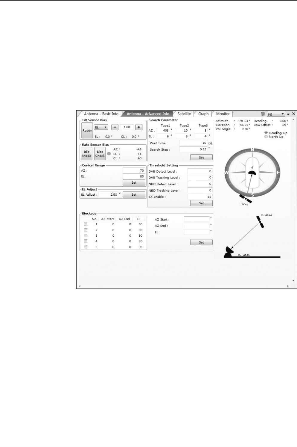
95
PC CONTROLLER SOFTWARE
2. Antenna – Advanced Info.
This view provides information on the Tilt Sensor Bias, Conical Range, EL Adjust,
Rate Sensor, Search Parameter and Block Zone.
-Tilt Sensor Bias: This maintains the elevation and the cross level axes
in order to keep the pedestal parallel to the horizon. Adjust the two solid-
state tilt sensors to provide absolute cross-level tilt of the antenna and el
evation feedback to eliminate long-term pointing drift (error). Tilt bias
must be adjusted when the antenna control board or sensor box is
replaced. If the bubble on the button level located on the sensor box is
not centered, follow the following steps to adjust the tilt sensor bias.
· Step 1. Enter Setup mode and press the “Ready” button to bring
the elevation and cross-level to 0.
· Step 2. Select “EL” from the drop down list and press Up and
Down arrow keys to adjust the bubble until it is located in the
center ring of the button level.
· Step 3. Select “CL” from the drop down list and press Up and
Down arrow keys to adjust the bubble until it is located in the
center ring of the button level.

v130 – Marine Satellite Communication System
96
· Step 4. Press the “Restart” icon to restart the antenna.
- Rate Sensor: is used to calibrate the DC voltage output from the three rate sen-
sors (azimuth, elevation, and cross-level). These are used to sense antenna motion
that corresponds to the ship’s motion (roll, pitch, and yaw) for stabilizing the ped-
estal. The DC voltage output from each of the rate sensors may vary by an amount
which is directly proportional to the direction and rate of motion induced on it.
Before calibrating the rate sensors located in the Sensor box, make sure that the
antenna is placed on a rigid and at platform. During the calibration process, any
motion of the antenna should be avoided as it can affect the antenna’s perfor-
mance. Proceed with the following steps to perform the calibration.
· Step 1. Enter Setup mode
· Step 2. Press the “Idle Mode” button to release the elevation and
cross level motor brakes while the antenna is in Setup mode.
· Step 3. Check whether or not the bubble is located at the center
of the button level. If not, move it to the center by following the
previous instruction of Tilt Sensor Bias adjus™ent.
· Step 4. Press the “Bias Check” button to calibrate the rate sensor.
A blue circle will be displayed next to the Bias Check button if the
calibration is completed. A red circle will be displayed if calibration
failed. A green circle will be displayed during the calibration
process.
- Conical Range: The relative force of the motors controlling azimuth and eleva-
tion. Set the conical range while the antenna is in tracking mode.
- EL Adjust: The elevation adjus™ent is to offset the angle difference between the
mechanical elevation angle and actual elevation angle. If this value is not properly
adjusted, the antenna may take longer time for satellite search or tracking.
- Search Parameter:
· Wait time: set the time-out for automatic initiation of a search after
the signal level drops below the pre-dened threshold value.

97
PC CONTROLLER SOFTWARE
· Search Step: set increment step size.
· Type 1 & Type 3 (Search 1 & 3) Range: set Search 1 & 3 search
range. Search 3 is conducted in a two-axis pattern consisting of
alternate movements in azimuth and elevation as it forms an
expanding square.
· Type 2 (Search 2) Range: is reserved for future use.
- Block Zone
Displays current block zones by azimuth and elevation sectors. Up to 5 block
zones can be programmed. Once the block zone is created, a blue shading area
will be displayed in the Antenna UI view on the right.
- Threshold Settings
· DVB Detect Level: displays and sets signal detection threshold
level when DVB tracking mode is in use.
· DVB Tracking Level: displays and sets signal tracking threshold
level when DVB tracking mode is in use.
· NBD Detect Level: displays and sets signal detection threshold
level when NBD tracking mode is in use.
· NBD Tracking Level: displays and sets signal tracking threshold
level when NBD tracking mode is in use.
· TX Enable Threshold: displays and sets TX enable threshold.

v130 – Marine Satellite Communication System
98
3. Satellite
This view provides information on the Satellite’s Information, Tracking Common
Information, DVB and NBD Tracking Transponder, LNB Local Frequency, and Sat-
ellite Library. This view shows a graphic UI of the current satellite that the antenna
is pointing at and the satellites that are located at a 180° arc on the horizon with
reference to the current position.
NOTE: Based on the satellite EIRP footprint and the size of the antenna, you may not
be able to track all the satellites visible in 180° arc.
- Tracking Information of Current Satellite: displays the current satellite’s name,
longitude position, and satellite skew of the satellite in the library.
- Tracking Common Information: displays the current LNB local oscillator fre-
quency that is in use and the corresponding voltage supplied. Selects the tracking
mode (DVB / NBD) to be used and sets polarization (Horizontal / Vertical) for the
RX pol and the TX pol.

99
PC CONTROLLER SOFTWARE
- DVB/NBD: sets tracking transponder
information for either DVB tracking mode (Verication Type, Frequency, Symbol
rate, and NID) or NBD tracking mode (Frequency and bandwidth).
NOTE: DVB and NBD parameter settings should only be changed by an authorized
service technician. Improper setting of these parameters will render your system
inoperable. Consult Intellian for changing antenna parameters.
- LNB Local Frequency: Displays or sets LNB local frequency and its corre-
sponding LNB voltage supplied. You may select pre-programmed LNB LO settings
from the drop down list. This procedure is same for both the Intellian Global VSAT
PLL LNB and any other LNB.
- Tracking Information of Library: Selecting this option enables “Add Satellite”,
“Edit Satellite” and “Delete Satellite” buttons.
· Eutelsat: Select 'ON' when the antenna is tracking an Eutelsat satellite.
With this option enabled, a dened skew angle for each Eutelsat satellite
is automatically applied without allowing a manual modication to the
skew offset value.
· Get Library From PC : opens the satellite library le (File format:*.ilf)
from the PC.
· Get Data From ACU: obtains the satellite information from the ACU.
· Load Satellite: uploads the satellite information to the ACU.
· Upload to ACU: uploads the satellite library to ACU.
· Edit Satellite: edits the satellite information of the selected satellite.
· Add Satellite: adds the satellite information as dened in the
current settings.
· Delete Satellite: deletes the selected satellite from the library.
· Save to PC: saves the current library settings to PC.
NOTE: It is required to click the "Save to PC" button after "Edit Satellite", “Add Satellite",
or "Delete Satellite" button is clicked.
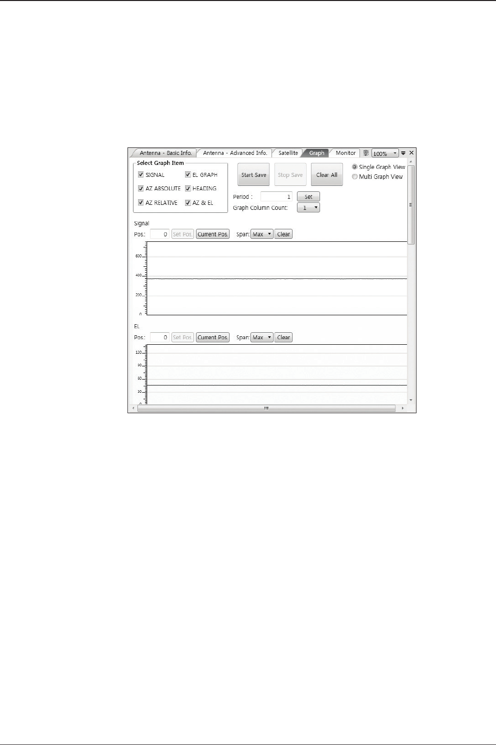
v130 – Marine Satellite Communication System
100
4. Graph View
This view provides information on Signal, Elevation (EL), Absolute AZ (Azimuth),
Relative AZ, Heading, AZ and EL in Single or Multi graph formats.
- Select Graph Item: shows the graphs of only the checked item(s) in a
Single or Multi Graph View.
- Single Graph View: shows Graph Views per each single Graph Item
selected in ‘Select Graph Item’.
- Multi Graph View: shows one large integrated Graph View of multiple
Graph Items selected in ‘Select Graph Item’.
- Start/Stop Save: the chosen item is saved within the data log. The data
log which stores the information displayed in the graphs can be later
used for a service technician to nd out a cause of any possible problem
to the antenna.
- Clear All: clears everything drawn on the Graph View window.
- Set Pos.: sets the current position as center value of each Graph Item.
- Current Pos.: moves to the location according to values of each Graph Item.
- Span: sets the Display Range(s) of each corresponding Graph Item.
- Period: displays and sets the signal sampling rate.
- Graph Column Count: makes all Graph Views show in either one or
two-column format.
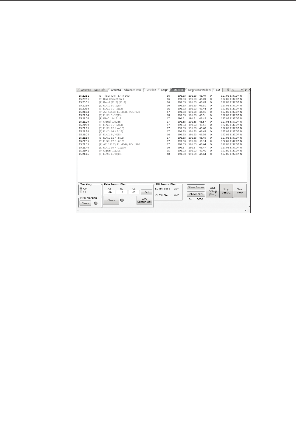
101
PC CONTROLLER SOFTWARE
5. Monitor
This view provides a UI which can monitor all data that has been received from the
ACU.
- Tracking: turns on or off the dish scan function. If the dish scan function
is disabled, the antenna will stop adjusting the antenna pointing angle in
order to optimize the receive signal level.
- Rate Sensor Bias: is used to calibrate the DC voltage output from the
three rate sensors (azimuth, elevation, and cross-level). These are used
to sense antenna motion that corresponds to the ship’s motion ( roll,
pitch, and yaw) for stabilizing the pedestal. You can nd the same
function in Antenna-Advanced View Tab.
- Show Param: shows the current antenna parameters.
- Check NID: veries the NID (network ID) of the current tracking tran
sponder. Press the NID button to obtain the NID only if the antenna is
locked onto the desired satellite .
- Debug (Start): starts the debug log of the antenna. The debug message
will be displayed once the debug button is pressed.
- Stop Debug: stops debug logging of the antenna.
- Save Debug (Start/Stop): starts or stops saving the debug log. This button is
enabled once the Start Debug button is pressed.
- Clear View: clears the debug message or log data in monitoring window.
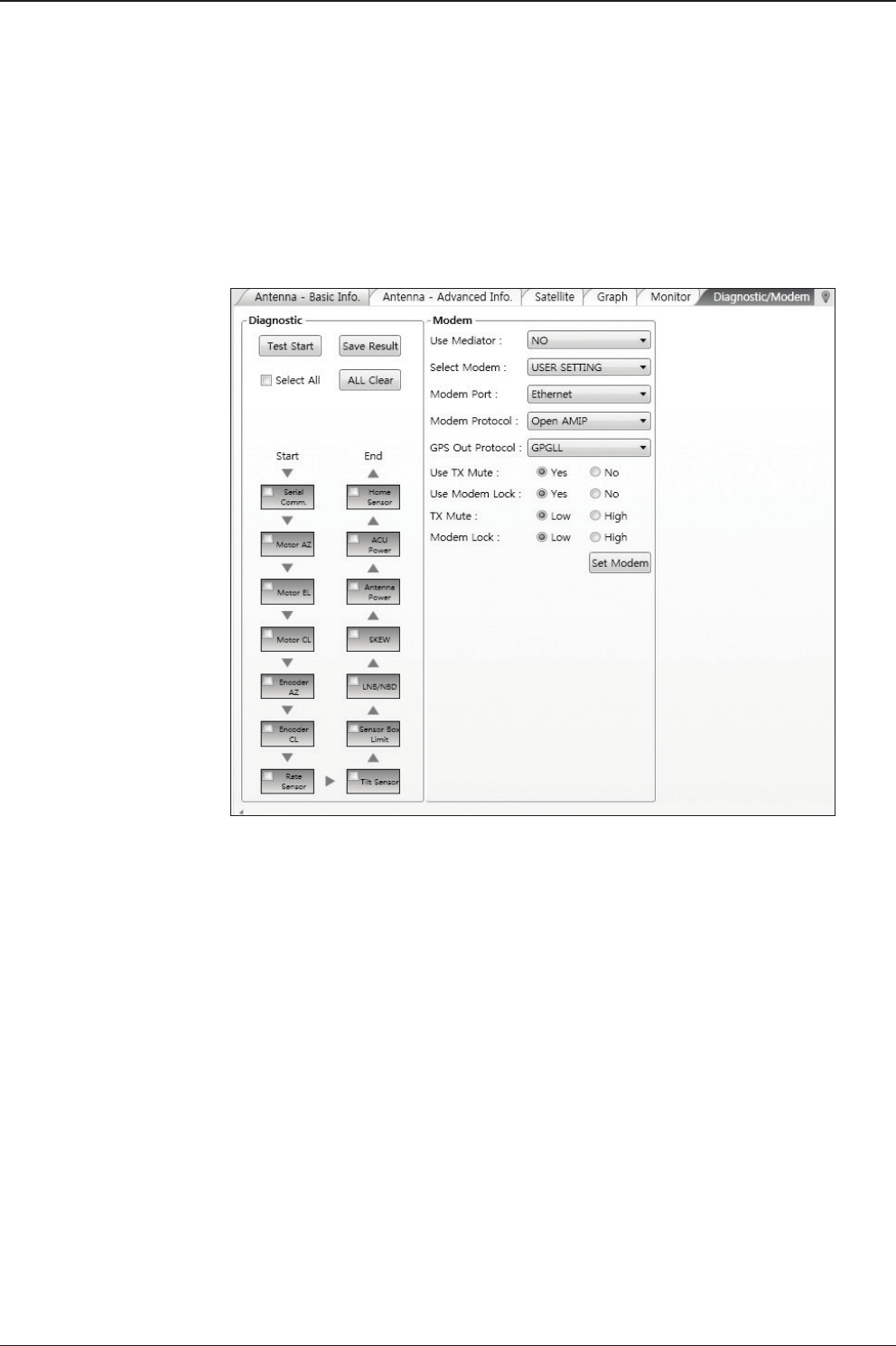
v130 – Marine Satellite Communication System
102
6. Diagnostic / Modem
This view provides Antenna Diagnostic Testing and also provides functions to set
up the interface between the ACU and the Intellian VSAT Mediator or the satellite
modem.
- Diagnostic : select to run a full diagnostic test or single diagnostic test.
"Green" indicator is displayed for the test under progress. "Blue" indi
cates the test result as Pass while "Red" indicates the result as Fail. "Yel
low" indicates the test has been skipped.
· Serial Comm.: tests the data communication between the antenna
and the ACU.
· Motor AZ: tests the azimuth motor.
· Motor EL: tests the elevation motor.
· Motor CL: tests the cross-level motor.
· Encoder AZ: tests the azimuth encoder.
· Encoder CL: tests the cross-level encoder.
· Rate sensor: tests the rate sensor.
· Tilt Sensor: tests the tilt sensor.
· Home sensor: tests the home sensor.
· ACU power: tests the ACU power to see whether or not it is
within the nominal operating range.

103
PC CONTROLLER SOFTWARE
· Antenna power: tests the antenna power to see whether or not it
is within the nominal operating range.
· Skew: tests the LNB skew motor.
· LNB/ NBD: tests the LNB and NBD (narrow band detector).
· Sensor Box Limit: tests the sensor box motor .
- Modem: sets the interface between the ACU and the Intellian Dual VSAT
Mediator or the satellite modem.
NOTE: Before setting this function, make sure connection of a RJ45 cable from the
Ethernet connector on the ACU to the modem or conect a 9 pin serial cable from
the RS232/422 connector on the ACU to the modem.
· Use Mediator: enables use of the Intellian Dual VSAT Mediator.
Use Mediator must be set to “NO” if there is no MEDIATOR
connected to the ACU. Improper setting of this parameter will
cause your ACU’s modem interface to work incorrectly.
· Select Modem: selects your modem type for loading pre-conguration
settings. If the ABS (auto beam switching) function is in use, select
either IDIRECT-AMIP or COMTECH-ROSS depending on which
type of modem is used.
· Modem Port: selects a proper data communications port (RS232/
422/ Ethernet) to interface with the modem.
· Modem Protocol: selects a proper communications protocol on
the ACU to interface with the modem (I/O Console/ Open AMIP/
Serial GPS/ ROSS/ VCAP/ ELEKTRIKOM AMIP/ GILAT-SE-II).
· GPS Out Sentence: selects GPS out sentence type (GPGLL/ GP
GGA/ Simple GPGGA).
· Use TX Mute: selects whether or not to use the “TX Mute”
function from the satellite modem. A transmit inhibit output from
the ACU will disable/ mute the modem transmit via a voltage
change whenever the antenna is blocked, searching, or is mis-
pointed 0.5 degrees from the peak satellite position.
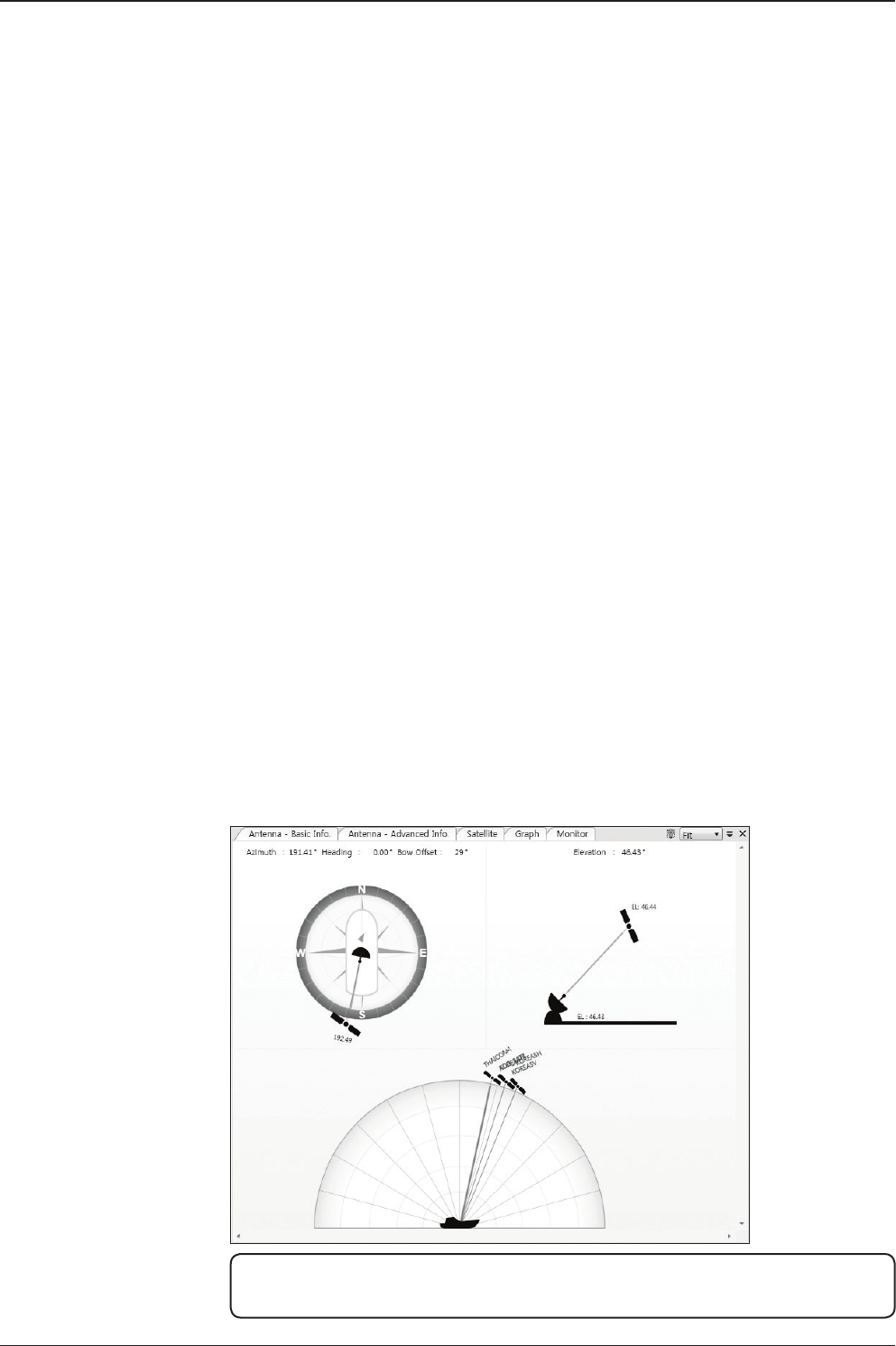
v130 – Marine Satellite Communication System
104
· Use Modem Lock: selects whether or not to use external lock
signal from the modem. “Use Modem Lock” will only be activated
when the modem protocol is set as I/O Console.
· TX Mute: TX Mute is a transmit inhibit output from the ACU to dis
able /mute the modem transmit through a 5 V (HIGH) or 0 V (LOW)
current whenever the antenna is blocked, searching, or is mis-
pointed 0.5 degrees from peak satellite position. TX Mute will only
be activated when modem protocol is set as I/O console.
· Modem Lock: is the modem lock output from the modem. It pro
vides a logic input through a 5V (HIGH) or 0 V (LOW) current to the
ACU to identify when the system is on the correct satellite.
“Modem Lock” will only be activated when modem protocol is set
as I/O Console.
7. GUI
This view shows a graphical representation of the current antenna position which
allows you to easily identify whether or not the antenna is aligned properly to the
target satellite or is in a block zone. In addition, this view shows the current satel-
lite that the antenna is pointed towards and the satellites that are located at a 180°
arc on the horizon, according to the current position.
NOTE: Based on the satellite EIRP footprint and the size of the antenna,
you may not be able to track all the satellites visible in 180° arc.
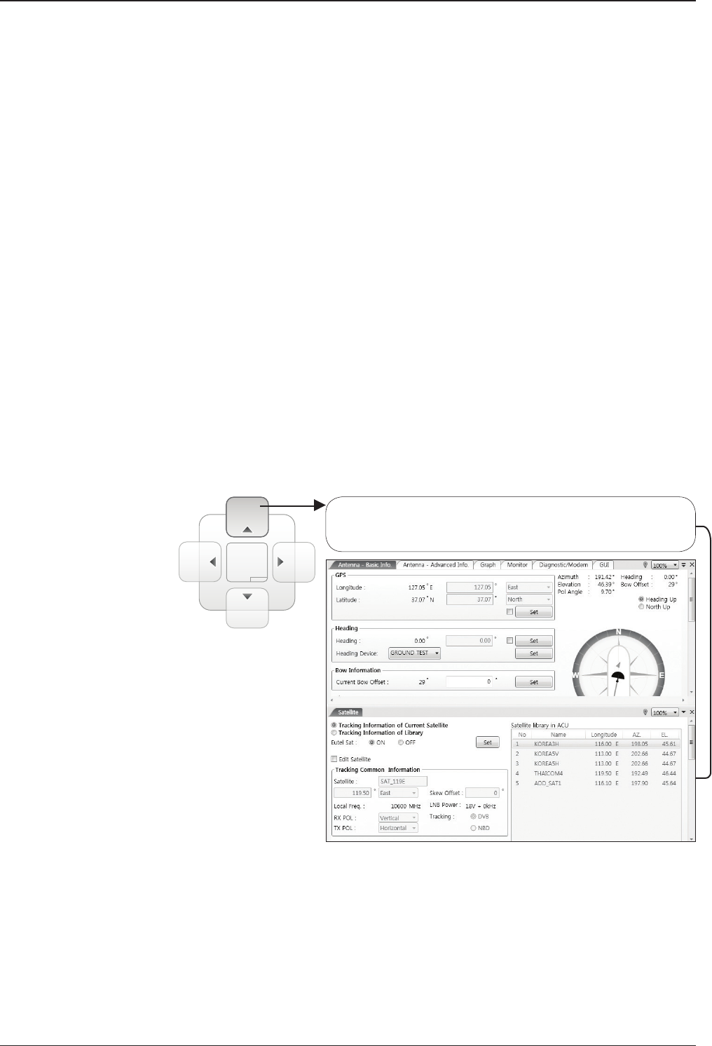
105
PC CONTROLLER SOFTWARE
8. Work View Functions
The seven Work View Tabs displayed in the Work View can be arranged in cus-
tomized layouts.
- Layout Formatting
· Each of the Work View Tab can be separated from the rest Tabs.
Click and hold the left mouse button on the Work View Tab’s
header and then drag a desired Tab out. When a Work View Tab
is separated from the rest of your Work View Tabs, again click
and hold the left mouse button on the Work View Tab’s header to
display a cross-shaped Navigator icon. While holding the mouse
button, bring the selected Work View Tab closer to the Navigator
icon and release the mouse button at your desired position (top,
left, right or bottom arrow). This time, the selected Tab will be
moved to the desired position.
Move the selected Work View Tab to the top position of the
Work View layout.
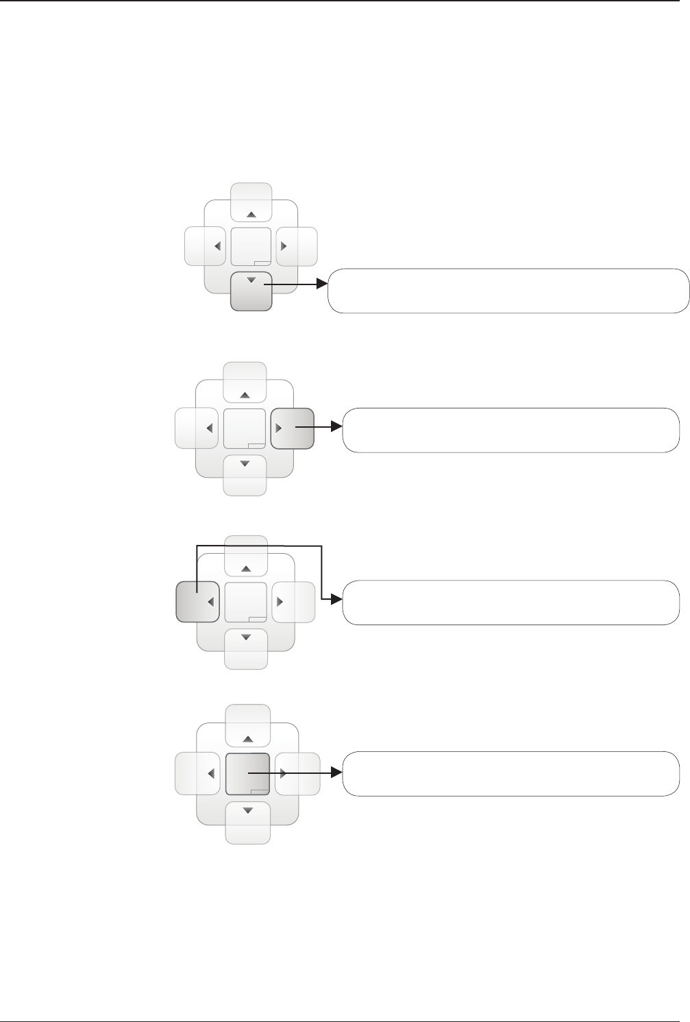
v130 – Marine Satellite Communication System
106
Move the selected Work View Tab to the right position of
the Work View layout.
Move the selected Work View Tab to the left position of
the Work View layout.
Move the selected Work View Tab to the center position
of the Work View layout.
Move the selected Work View Tab to the bottom position of
the Work View layout.
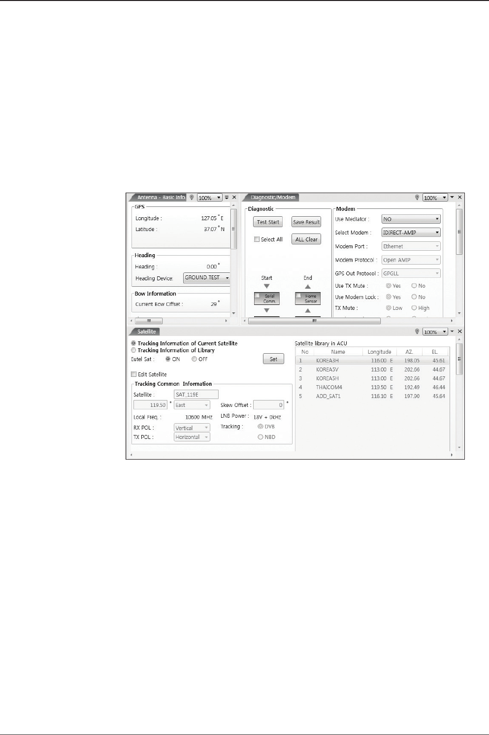
107
PC CONTROLLER SOFTWARE
You can also drag multiple Work View Tabs into a customized layout in the same
manner. Click and hold left mouse button on each Work View Tab’s header and
drag it onto a desired arrow on the Navigator icon. Then each Work View Tab can
be placed to the desired positions as shown in the gure below.
The Navigator will appear in each area your mouse pointer is located. To return to
the default layout, select the Default Layout toolbar menu.
- Horizontal or Vertical Tab Group
The Work View Tabs can be also aligned horizontally or vertically. Without
dragging them out, right-click the mouse button on a desired Tab header
and select ‘New Horizontal Tab Group’ or ‘New Vertical Tab Group’
option. Selecting ‘New Horizontal Tab Group’ will separate a selected Tab
from the rest of other Tabs then arrange it in a horizontal format. Likewise,
selecting ‘New Vertical Tab Group’ will separate a selected Tab from the
rest of other Tabs then arrange it in a vertical format.
- Closing the Work View Tab
To close the Work View Tab, right-click the mouse button on a desired
Tab header and select ‘Close’ option in the drop down list. To close all
Work View Tabs except the selected Tab, select ‘Close All But This’
option in the drop down list.
- Zoom Tool
Using the Zoom tool, you can easily select the magnication you want by
using Zoom In and Zoom Out bar, and Fit in Work View button.
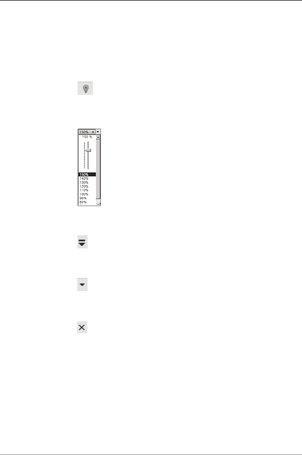
v130 – Marine Satellite Communication System
108
Fit Work View Button: ts the current view to the Work View window size. The but-
ton toggles between the t view and the previous view.
Zoom In and Zoom Out Bar: zooms in and out to expand and reduce the View to
the desired size. (The zoom changes in 10% increments.)
View Switch Button: displays a list of the current views in a list. Choosing one of
these views will display the selected view in the Work View window.
View Name Button: displays the current Work View name.
Close View Button: closes the current view.

109
APTUS WEB
APTUS WEB
Introduction
Main Page
Page Login
Top menus
Dash Board & Information
Antenna Settings
Ship setting
Antenna Position & Parameters
Tracking setting
Modem Setting
Diagnostic
Library Setting
Firmware & Conguration
Antenna Firmware Upgrade
Antenna Log
Antenna Backup & Restore
Administration
Network Setting
SNMP Setting
User Management
iARM Upgrade
iARM Save & Reboot
Antenna Event Log
Intellian Network Devices
v130 – Marine Satellite Communication System
110
Introduction
With embedded Aptus Web software, the v-Series can be monitored, controlled,
and diagnosed remotely from anywhere, anytime through the TCP/IP protocol.
This not only can save time but also save the cost generated from the hundreds
of routine maintenance activities such as operating rmware upgrades, tracking
parameters resets, and system diagnostic.
How to access Aptus Web:
1. Connect an Ethernet Cable between your PC and the Management Ethernet Port.
2. Enter the ACU's IP address (192.168.2.1) into your web browser's address bar to
login into the ACU’s internal HTML page, if this system has not been changed from
the ACU’s factory default.
NOTE: Aptus Web can be displayed in Internet Explorer 7 or later and is also compatible
with Firefox and Chrome web browsers.
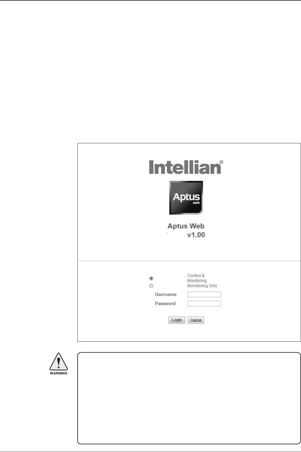
111
APTUS WEB
Page Login
1. Choose either to Control & Monitor the ACU (Control & Monitoring) or Only
Monitor the ACU (Monitoring Only).
2. Log into the ACU by typing in User Name and Password information. If this
system has not been changed from the factory default:
• User Name: intellian
• Password: 12345678
WARNING: The Control & Monitoring Mode will be switched to the Monitoring
Only Mode in the following cases;
• If PC Software (Aptus) is connected using TCP/IP Communication while
Aptus Web Control is in use.
• If Control & Monitoring Mode is accessed while PC Software is running via
TCP/IP Communication. In this case, the web page will display a pop-up
message asking if you want to disconnect the PC Software network
connection. If you select ‘No’, the Control & Monitoring Mode will be
switched to the Monitoring Only Mode.
Main Page
v130
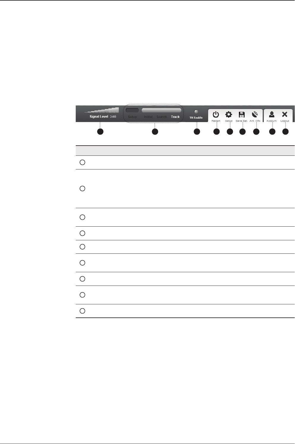
v130 – Marine Satellite Communication System
112
No. Item Description
1Signal Level Display current signal level.
2Antenna
status
- Setup: Displays whether or not the antenna is in SETUP
mode. The indicator shows “Blue” in the SETUP mode.
- Initial: Antenna or ACU is initialized.
- Search: Antenna is searching a target satellite.
- Track: Antenna is tracking the target satellite.
3TX Enable/
TX Disable
Displays whether or not the antenna is able to transmit the
data
4Restart Restart the antenna system.
5Setup Enter SETUP mode.
6Save Sat. Save current satellite settings.
Bow offset will be adjusted and saved automatically.
7Ant. Info Obtain current antenna information.
8Account Shortcut to User Management menu. Change login ID and
Password.
9Logout Logout the ACU's internal HTML page.
Top Menus
Once you log in, the following information and menus are displayed.
1 3 4 5 678 9
2
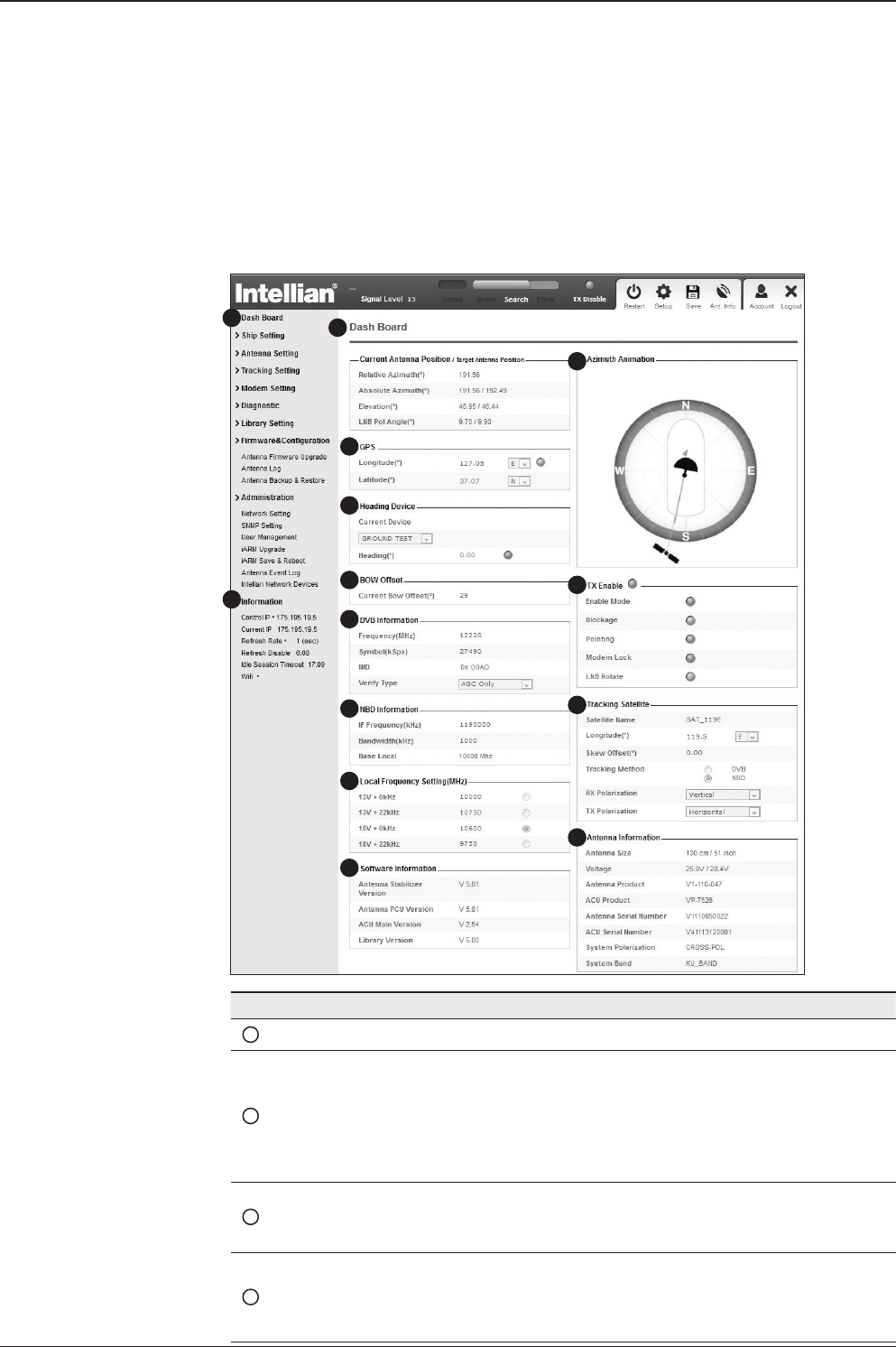
113
APTUS WEB
No. Item Description
1Dash Board Displays current antenna status to be quickly monitored.
2
Current Antenna
Position /
Target Antenna
Position
Displays current antenna position.
- Relative Azimuth: displays antenna relative AZ angle.
- Absolute Azimuth: displays antenna absolute AZ angle.
- Elevation: displays antenna elevation angle.
- LNB Pol Angle: displays LNB pol angle.
- Heading: displays ship’s heading information
3GPS
Displays current GPS information.
- Longitude (East / West)
- Latitude (North / South)
4Heading
Device
Displays current Heading Device: NONE, NMEA, NMEA 2000,
Ground test If the ship’s gyrocompass input is other than NMEA
separate purchase of NMEA Converter is required.
- Heading: displays ship’s heading information.
Dash Board & Information
On the left side of the page, Dash Board and Information menus are displayed
as below to provide quick monitoring of the antenna status and settings. Other
menus are displayed only in the Control & Monitoring mode and their functions will
be described in the next sections.
1
3
4
5
6
7
8
9
10
11
12
13
14
2

v130 – Marine Satellite Communication System
114
5BOW Offset Display current bow offset
6DVB Information
Displays DVB tracking mode’s current tracking information.
- Frequency: displays tracking frequency.
- Symbol rate: displays symbol rate.
- NID: displays network ID.
- Verify type: displays verication typ
(AGC, DVB, DVB Decode)
7NBD Information
Displays NBD tracking mode’s current tracking information.
- Frequency: displays tracking IF frequency.
- Bandwidth: displays detection bandwidth.
8Local Frequency
Setting (MHz) Displays current LNB’s local frequency and voltage
9Satellite
Information
Displays current Antenna and ACU rmware versions and Satellite
Library version installed in the system.
- Antenna POL Version
(It will display "v-----" if there is no Pol Control Board installed.)
- Antenna Stabilizer Version
- Antenna PCU Version
- ACU Main Version
- Library Version
10 Azimuth
Animation
Shows a graphical representation of the current antenna position
to identify whether or not the antenna is aligned properly to the
target satellite or is in a block zone.
11 TX Enable
Displays whether or not the antenna is able to transmit the data.
The TX function will only be enabled (shows BLUE dot ) only if all of
the factors listed below shows “BLUE” dot. Exception: If “Use TX
Mute” is set as “NO”, the TX function will be enabled regardless of
which factor listed below shows “gray” dot or “red” dot.
- Enable Mode: antenna is not in SETUP mode.
- Blockage: antenna is not facing the predened block zone(s). -
Pointing: antenna is pointing to the target satellite.
- Modem Lock: satellite modem is sending a logic input to the
ACU to identify when the antenna tracks on the correct satellite.
- LNB Rotate: LNB is not rotating.
12 Tracking
Satellite
Displays current tracking mode.
- Satellite: displays satellite name.
- Longitude: displays satellite orbit position.
- Skew Offset: displays Skew offset.
- Tracking Method: displays current tracking mode (DVB/ NBD).
- RX Polarization: displays current RX polarization.
- TX Polarization displays current TX polarization.
13 Antenna
Information Displays the product information
14 Information
- Control IP: Displays current IP that controls the ACU.
- Current IP: Displays current IP address.- Refresh Rate: Displays
screen refresh rate (default: 1 sec.) - Refresh Disable: Displays time
out.
The screen will not refresh once the time-out shows 0:00.
Exception: If the Refresh Disable Time is set to “OFF” in the Net-
work Setting page, then the clock will show “--:--“ and
system will keep monitoring all activities regardless of timeout.
- Wi : Displays Wi on/off switch
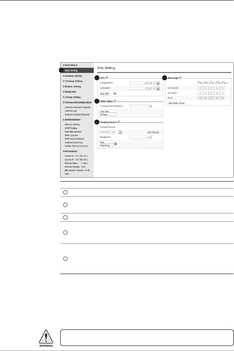
115
APTUS WEB
No. Item Description
1Ship Setting Set the ship information and block zone.
2GPS
Set GPS information.
- Longitude (East/West)
- Latitude (North/South)
3Bow Offset Set Bow Offset if needed.
4Heading Device Set ship’s heading device (NONE, NMEA, NMEA2000,
Ground Test) and ship’s heading information
5Blockage
Set the antenna’s block zones up to 5 by azimuth and eleva-
tion sectors. AZ. START is where the relative azimuth starts
and AZ. END is where the relative azimuth ends (Range: 0 -
360°). EL. Limit is where the elevation starts (Range 0 - 90°).
WARNING: Enter the SETUP mode for conguration. Tick the checkbox before
modifying the settings. After conguration, click ‘Set ...’ button to submit the settings.
Ship Setting
Antenna Settings
1
3
4
5
2
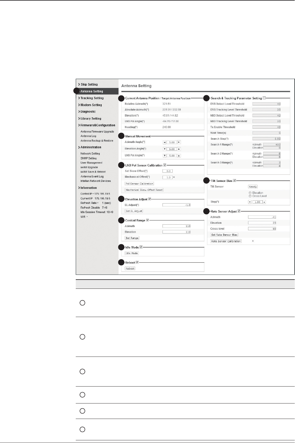
v130 – Marine Satellite Communication System
116
Antenna Position & Parameters
No. Item Description
1Antenna Setting
Set current antenna position and Search and Tracking
parameters. These parameters should only be changed by
an authorized service technician. Improper setting of these
parameters will render your system inoperable.
2Current Antenna Position/
Target Antenna Position
Display current antenna position.
-
Relative Azimuth: display antenna relative AZ angle.
-
Absolute Azimuth: display antenna absolute AZ angle.
- Elevation: display antenna elevation angle.
- LNB Pol Angle: display LNB pol angle.
- Heading: display ship’s heading information.
3Manual Movement
Move antenna azimuth and elevation angles and LNB pol
angle to nd the desired satellite manually. LNB Pol Angel
can be adjusted at any time either in SETUP Mode or
Tracking Mode.
4LNB Pol Sensor Calibration Calibrate the LNB pol angle when the control board, po-
tentiometer or belt is replaced.
5Elevation Adjust Adjust the elevation to offset the angle difference between
the mechanical elevation angle and actual elevation angle.
6Conical Range
The relative force of the motors controlling azimuth and
elevation. Set the conical range while the antenna is in
tracking mode.
1
3
4
5
6
7
8
9
10
11
2

117
APTUS WEB
WARNING: Tick the checkbox before modifying the settings. After conguration, click
'set...' button to submit the settings.
No. Item Description
7Idle Mode
Release the elevation and cross level motor brakes while
the antenna is in SETUP mode. The antenna can be
moved manually during the mode.
8Reboot Reboot the system.
9Search & Tracking
Parameter Setting
DVB Detect and Tracking Level Threshold: display / set
current detect level threshold and tracking level threshold
when DVB tracking mode is chosen to be used.
- NBD Detect and Tracking Level Threshold: display / set
current detect level threshold and tracking level threshold
when NBD tracking mode is chosen to be used. - TX En-
able Threshold: display / set TX enable threshold. - Wait
time: set the time-out for automatic initiation of a search
after the signal level drops below the pre-dened threshold
value.
- Search Step: set increment step size.
- Search 1 & 3 Range: set Search 1 & 3 search range.
Search is conducted in a two-axis pattern consisting of
alternate movements in azimuth and elevation as forming
expanding square.
- Search 2 Range: is reserved for future use.
10 Tilt Sensor Bias
Adjust the two solid-state tilt sensors used to provide
absolute cross-level tilt of the antenna and elevation feed-
back to eliminate long-term pointing drift (error). Tilt bias
is required to be adjusted when the antenna control board
or sensor box is replaced. Check to see whether or not the
bubble is located at the center of the level vial.
11 Rate Sensor Adjust
Calibrate DC voltage output from the three rate sen-
sors used to sense antenna motion in azimuth, elevation
and cross-level axes. During the calibration process,
the antenna should avoid any motion as it can affect the
antenna’s performance.
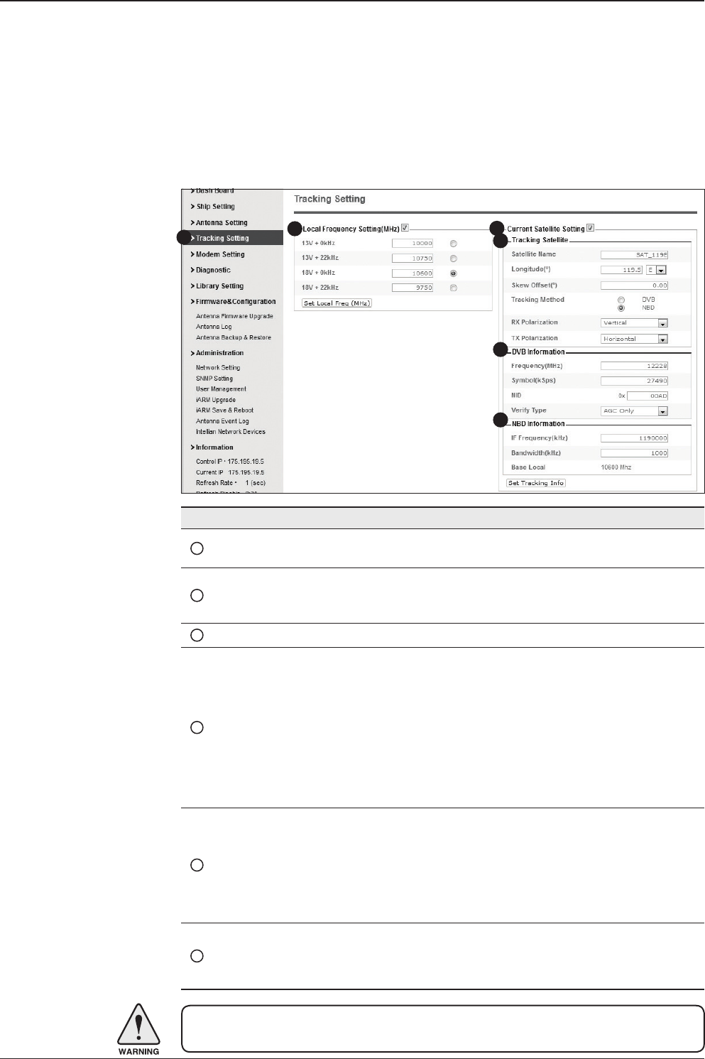
v130 – Marine Satellite Communication System
118
Tracking Setting
No. Item Description
1Tracking Setting Display or set current tracking mode and tracking
frequency of the target satellite.
2Local Frequency Setting
(MHz)
Display and set LNB’s local frequencies. Display
current LNB local frequency which is in use and
voltage.
3Current Satellite Setting Display and set current satellite setting.
4Tracking Satellite
Display and set current tracking mode.
- Satellite: display and set satellite name.
- Longitude: display and set satellite orbit position.
- Skew Offset: display and set Skew offset.
- Tracking Method: display and set current tracking
mode (DVB/ NBD).
- RX Polarization: display and set current RX
polarization.
- TX Polarization display and set current TX
polarization.
5DVB Information
Display and set DVB tracking mode’s tracking
information.
- Frequency: display and set tracking frequency.
- Symbol rate: display and set symbol rate.
- NID: display and set network ID.
- Verify type: display and set verication type (AGC,
DVB, DVB Decode)
6NBD Information
Display and set NBD tracking mode’s tracking
information.
- Frequency: display and set tracking IF frequency.
- Bandwidth: display and set detection bandwidth.
WARNING: Tick the checkbox before modifying the settings. After conguration, click
'set...' button to submit the settings.
13
4
5
6
2
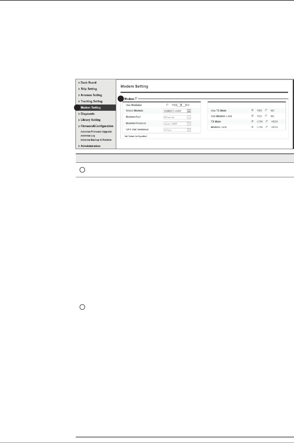
119
APTUS WEB
Modem Setting
1
2
No. Item Description
1Modem Setting Set the modem interface.
2Modem
- Use Mediator: enable the usage of Mediator if the antenna is
connected to the Intellian Dual VSAT Mediator. Use Mediator
must be set to “NO” if there is no MEDIATOR connected to the
ACU. Improper setting of this parameter will cause your ACU’s
modem interface to work incorrectly.
- Select Modem: is to select a proper data communication port
and protocol on the ACU to interface with the satellite modem.
The settings related to the modem interface will be set auto-
matically once the modem type is selected (USER SETTING,
IDIRECT-I/O, IDREICT-AMIP, COMTECH-I/O, COMTECH-
ROSS, HUGHES, SATLINK-SERIAL, SATLINK-VACP, ELEK-
TRIKOM-AMIP, GILAT-SE-II).
However, it is required to set the related settings separately if
USER SETTING is selected.
- Modem Port: is to select a proper data communication port
on the ACU to interface with the satellite modem (RS232/422/
Ethernet).
- Modem Protocol: is to select a proper communication protocol
on the ACU to interface with the modem (I/O Console, Ope-
nAMIP, Serial GPS, ROSS, VACP, ELEKTRIKOM AMIP, GILAT).
- GPS Out Sentence: is to select the GPS out sentence type
(GPGLL/GPGGA/SIMPLE GPGGA)
- USE TX Mute: is to select whether or not to use TX mute
function from the satellite modem.
- USE Modem Lock: is to select whether or not to use external
lock signal from the satellite modem.
- TX Mute: is a transmit inhibit output from the ACU to disable/
mute the modem transmit through a 5V (High) or 0V(LOW)
current whenever the antenna is blocked, searching, or is
mispointed 0.5° from peak satellite position.
- Modem Lock: is the modem lock output from the modem
which provides a logic input through a 5V (High) or 0V(LOW)
current to the ACU to identify when it is on the correct satellite.
Note: TX Mute and Modem Lock items will only be activated
when the modem protocol is set as I/O Console.
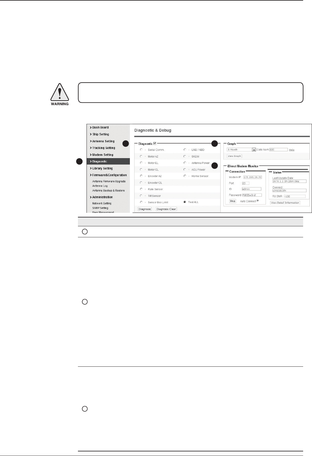
v130 – Marine Satellite Communication System
120
Diagnostic
No. Item Description
1Diagnostic Execute antenna diagnostic test.
2Diagnostic
Select to run a full diagnostic test or single diagnostic test.
- Serial Comm.: test the data communication between the
antenna and the ACU.
- Motor AZ: test the azimuth motor.
- Motor EL: test the elevation motor.
- Motor CL: test the cross-level motor.
- Encoder AZ: test the azimuth encoder.
- Encoder CL: test the cross-level encoder.
- Rate Senor: test the rate sensor.
- Tilt Sensor: test the tilt sensor.
- Sensor Box Limit: test the sensor box motor.
- LNB/NBD: test the LNB.
- SKEW: test the LNB pol motor.
- Antenna Power: test the antenna power.
- ACU Power: test the ACU power.
- Home Sensor: test the home sensor
- Test ALL: test all devices.
3Graph
Select to view a graph of AZ Absolute, AZ Relative, EL and
Heading data of the antenna.
- A Month: display all data within a month
- A Week: display all data within a week
- A Day: display all data in a day
- Real-time: display data in real time. Press F5 button to refresh.
- Data Num: set the maximum number of graph data set to be
displayed.
- View Graph: select to view the data graph.
WARNING: Ensure to tick the checkbox before modifying the settings. Select ‘Set
Modem Conguration’ to conrm the modem settings congured.
1
2 3
4

121
APTUS WEB
4
iDirect Modem
Monitor
(OpenAMIP only)
Displays iDirect Modem status and control connection. This
menu appears only when IDIRECT-AMIP protocol is selected at
Modem Setting page.
- Connection: control modem connection.
- Modem IP: iDirect modem IP
- Port: Connection ID for telnet
- Password: Connection password for telnet
- Start(Stop): Connect to telnet or disconnect
- Auto Connect: Enabling Auto Connect and rebooting the ACU
will save connection data and will auto connect once ACU is
powered on next time.
- Status: Displays iDirect modem status
- Last Update Date: Displays last updated data and time of the
iDirect modem data
- Connect:Displays connection status (INACTIVE, CONNECT-
ING, LOGGEDIN, Black data indicates being INACTIVE)
- RX SNR: Displays RX SNR data.
- View Detail Information: Select to view detail information
- Status: Displays last update date and connection status.
- Information : Displays rx snr, tx power, tx power min, rx power,
tx power max, tx power, ref, latlong.
- Option File Information: Displays information about VERSION,
MOBILE, LOCAL and ACU PORT
WARNING: Tick the checkbox before modifying the settings. Click Diagnosis button to
execute diagnostic test. To clear previous diagnosis result, click Diagnosis Clear button.

v130 – Marine Satellite Communication System
122
Library Setting
No. Item Description
1Library Setting Display and set the satellite library information.
2Library
- Get Library from ACU: Obtain satellite information installed in the
ACU.
- Open Library from PC: open the satellite library le from the
supplied Intellian CD or from the external hard drive/PC.
(File format: *.ilf)
- Upload Library to ACU: upload the satellite library le to ACU.
- Save as Library to PC: save the current library setting to the PC.
3Load Satellite
Select the satellite that you wish to track and press Load Satellite
button to load the selected satellite.
4Selected
Satellite Setting
Displays selected satellite information.
5Tracking
Satellite
- Satellite: displays satellite name.
- Longitude: displays satellite orbit position.
- Skew offset: displays Skew offset.
- Tracking method: displays current tracking mode (DVB/NBD)
- RX polarization: displays current RX polarization.
- TX polarization: displays current TX polarization.
6DVB Information
- Displays DVB tracking mode's tracking information.
- Frequency: displays tracking frequency.
- Symbol rate: displays symbol rate.
- NID: displays network ID.
- Verify type: displays verication type (AGC only, DVB lock, DVB
decode, DSS decode)
7NBD Information
Displays NBD tracking mode's tracking information.
- Frequency: displays tracking frequency.
- Bandwidth: displays detection bandwidth.
8Local Frequency
Setting (MHz)
Displays LNB local frequency (MHz) and voltage.
1
3
4
5
6
7
8
2

123
APTUS WEB
Antenna Firmware Upgrade
Firmware & Conguration
No. Item Description
1Antenna Firmware
Upgrade Upgrade antenna and ACU rmware version.
2New Antenna
Firmware
Browse and select the rmware package le to upload and
click Start Upload button.
3Current Running
Version
Display current rmware version (Antenna STABILIZER,
Antenna PCU, ACU main, Library)
4Cold Rollback
Display Previous/Latest Package version and rollback
rmware to Previous or Latest version. Other functions
cannot be operated while rollback is in progress.
13
4
2
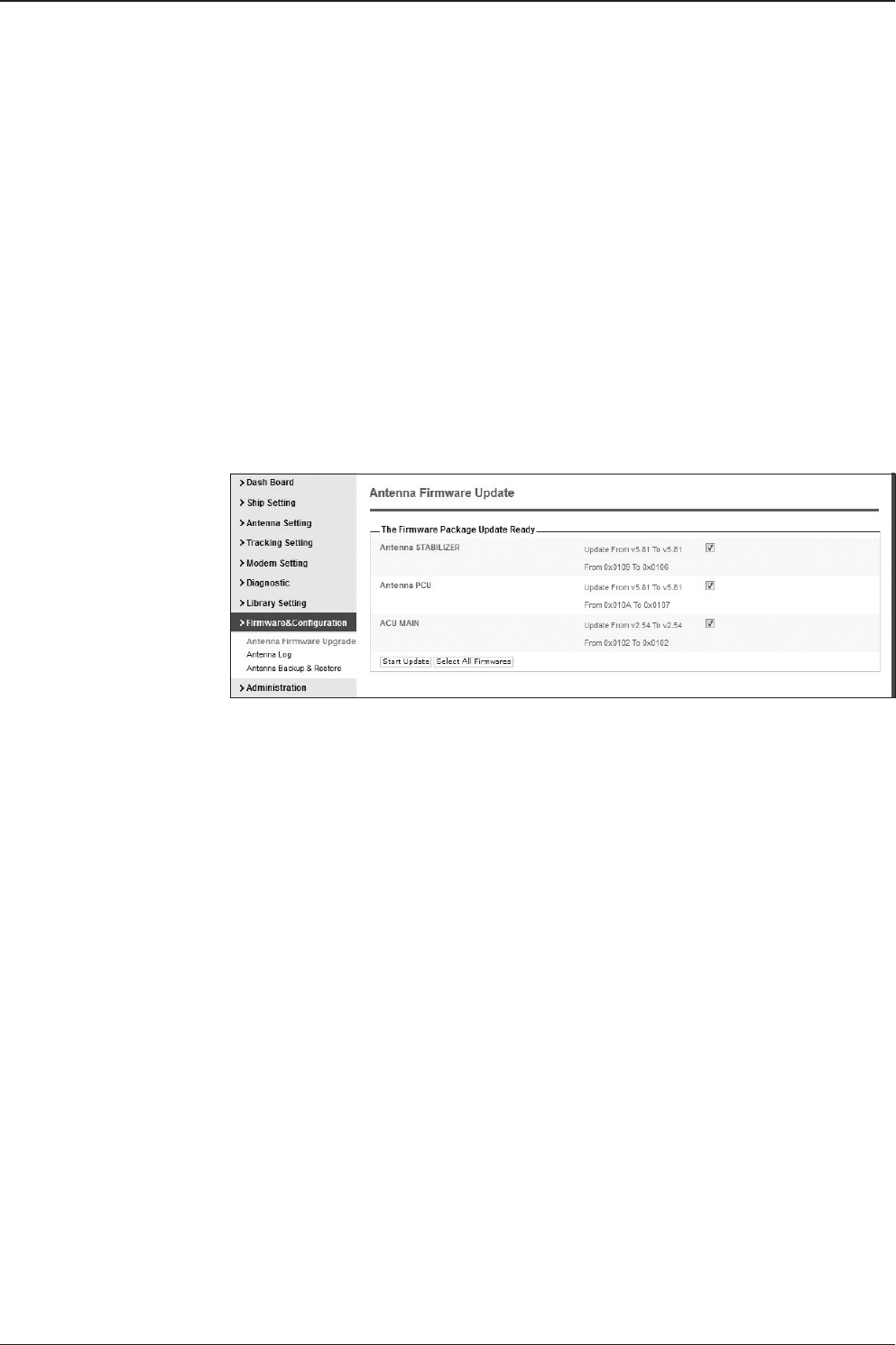
v130 – Marine Satellite Communication System
124
Upgrade procedures:
1. Select the upgrade package le.
2. Click on “Start Upload” button to transfer the Firmware package le (“*.fwp”) to iARM
module.
3. After the package le is transferred, it’ll show “upgrade from vx.xx Version to vx.xx
Version”. Enable the check box to select the rmware le that you wish to upgrade.
To select all rmware les, click Select All Firmwares.
4. Click on “Start Upgrade” button.
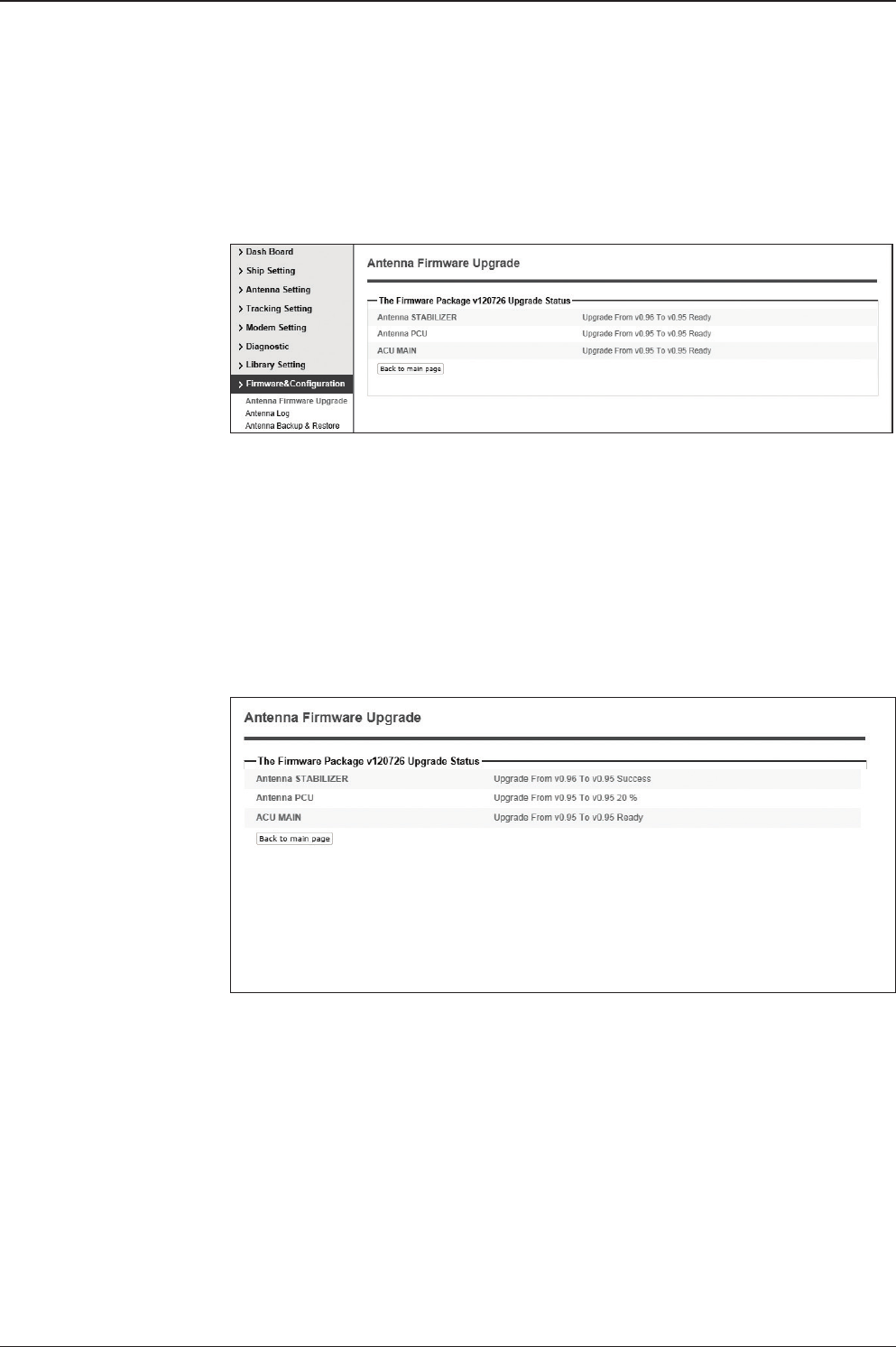
125
APTUS WEB
Firmware upgrade
status page
Upgrade process
status page
5. It'll display information about the upgrade process status on full screen.
6. If the rmware is successfully upgraded, it'll display "The rmware update is
completed."
7. Click on "Back to main page" to go out of the screen.
To verify the upgraded rmware version, go to Dash Board > Software Information.
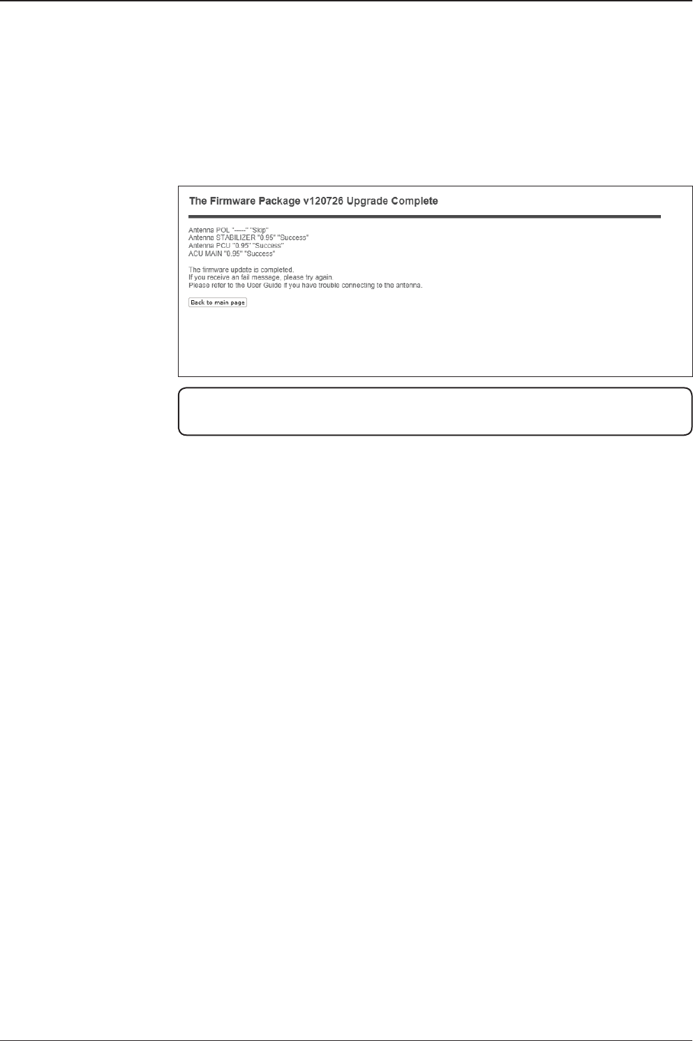
v130 – Marine Satellite Communication System
126
Upgrade complete
page
NOTE: To roll back to the previous rmware package version or latest package version,
select Rollback Upgrade menu on the Antenna Firmware Upgrade page.
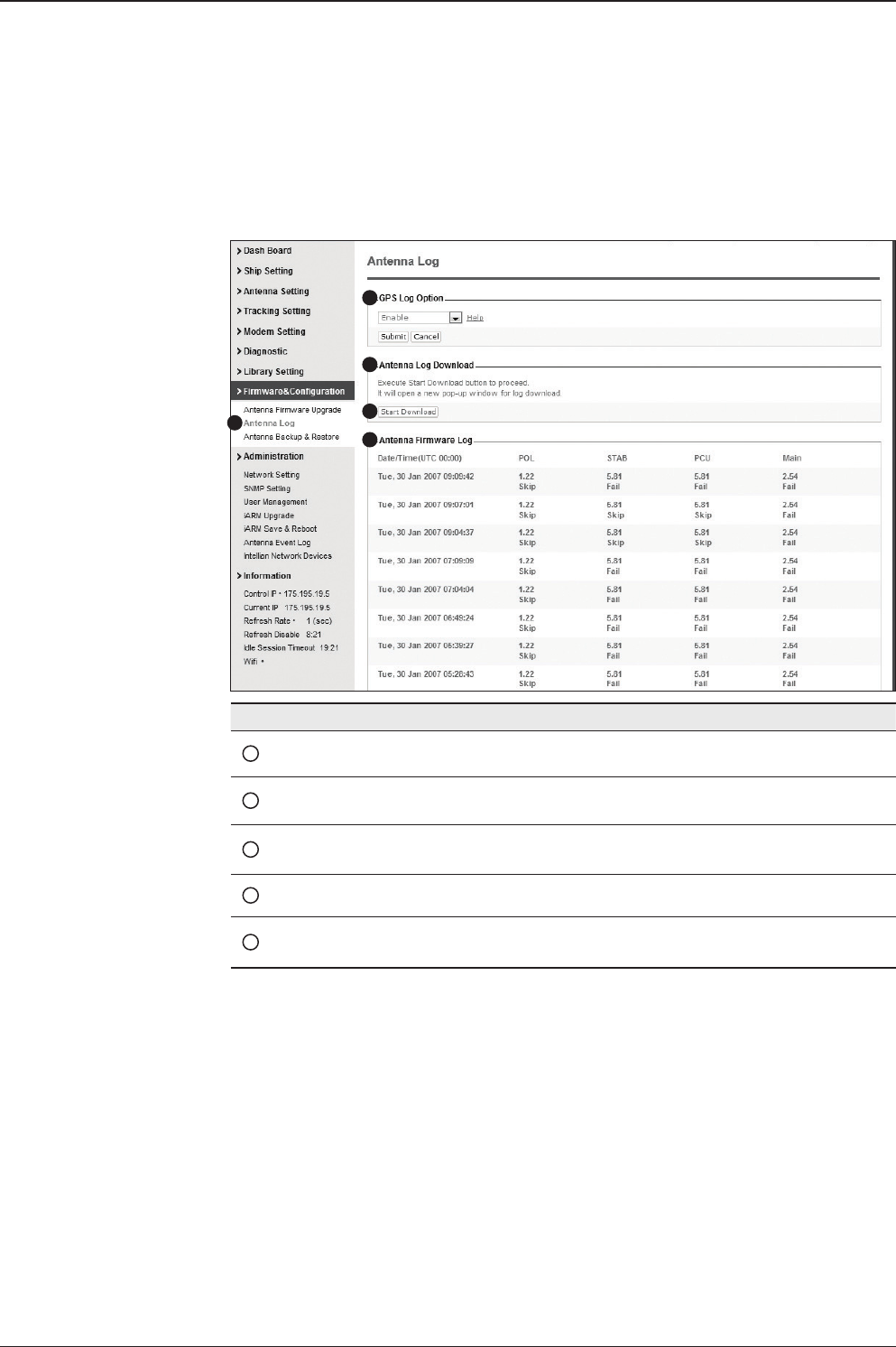
127
APTUS WEB
Antenna Log
No. Item Description
1Antenna Log Displays antenna log data
2GPS Log Option Disable/Enable to save GPS information in the antenna log le.
3Antenna Log
Download Download the log le. Select start download button to proceed.
4Start Download Download the antenna log information.
5Antenna
Firmware Log Display log information of rmware upgrade.
1
2
3
4
5
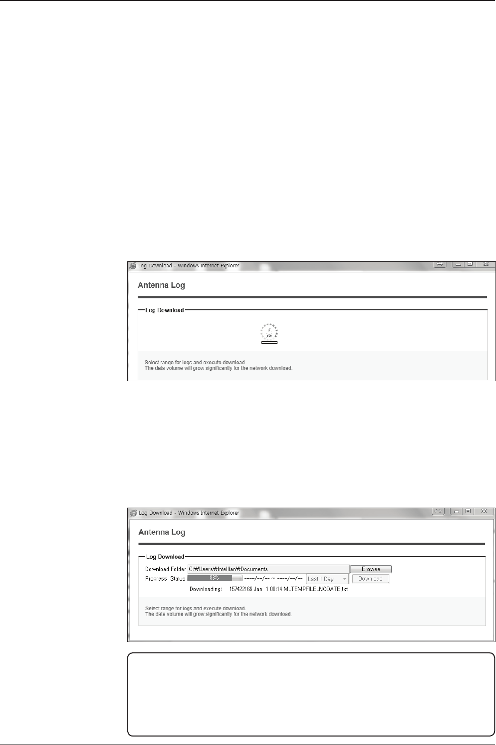
v130 – Marine Satellite Communication System
128
Log Downloade procedures:
1. Select ‘Start Download’ button.
2. To run Java applications you must have Java Runtime Environment
JRE) version 6.0 and above installed in your PC/ laptop when you
access the antenna log page for rst time. Click “Run” button on
the popup message “The application’s digital signature cannot be
veried. Do you want to run the application? ” to install the Applet.
Refer to Appendix for Java Installation Instructions if the system
does not display the popup message.
3. Select ‘Browse’ to browse the target directory of the antenna log le.
4. Select log period for le download.
- Last 3 Months: download the antenna log information for the past three
months.
- Last 1 Month: download the antenna log informaiton for the past one month.
- Last 1 week: download the antenna log information for the past one week.
- Last 1 Day: download the antenna log information for the past one day.
5. Select ‘Download’to download the log le to the target directory according to the
selected log period.
NOTE: You can choose to Enable or Disable the GPS tracking function. Liability for
information that is disclosed when GPS is enabled is solely the operators responsibility
and it is up to the operator on whether or not to provide their GPS information to third
parties. Any issues regarding safety and privacy when turning on the GPS function is
solely up to the user. Intellian is not responsible for information that is disclosed when
the GPS function is enabled.
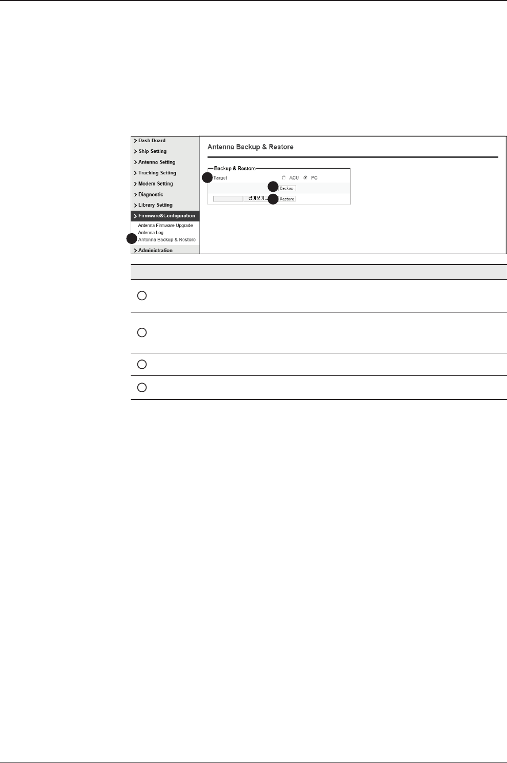
129
APTUS WEB
Antenna Backup & Restore
No. Item Description
1Antenna Backup & Restore Enter Backup & Restore page. (Setup mode is
required)
2Target
Backup antenna information to ACU/PC or
restore antenna by using the saved information
from ACU/PC.
3Backup Backup antenna information.
4Restore Restore antenna information.
1
3
4
2
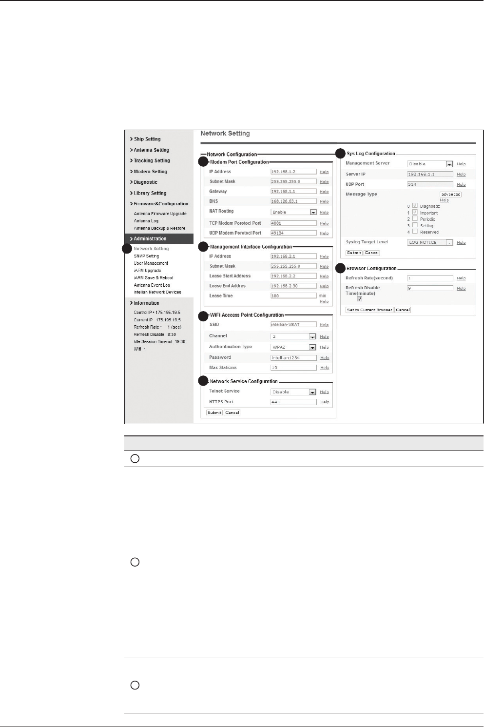
v130 – Marine Satellite Communication System
130
Administration
Network Setting
13
4
5
6
7
2
No. Item Description
1Network Setting Enter network setting page.
2Modem Port
Conguration
Modify ACU’s Internal IP address and press Submit button. Go
to “Save & Reboot” page and press Save & Reboot button to
validate the changes.
- IP Address : Factory default(Primary:192.168.0.223)/
(Secondary:10.10.1.1).
- Subnet Mask : Factory default(255.255.255.0).
- Gateway : Factory default(192.168.0.254).
- DNS : Current default DNS Address is assigned to.
- NAT Routing : Enable/Disable NAT routing.
- TCP Modem Protocol Port : TCP port number for modem
protocols using TCP as transport.
- UDP Modem Protocol Port : UDP port number for modem
protocols using UDP as transport.
3
Management
Interface
Conguration
Modify Management Port’s network conguration and press
Submit button. Go to “Save & Reboot” page and press Save &
Reboot button to validate the changes.

131
APTUS WEB
- IP Address : ACU front network port /Factory default(192.168.2.1).
- Subnet Mask : Factory default(255.255.255.0).
- Lease Start Address : Lease IP address start range.
- Lease End Address : Lease IP address end range.
- Lease Time : Lease IP address update time.
4
WiFi Access Point
Conguration
- SSID : The SSID is the network name shared among all
devices in a wireless network. The SSID must be identical
for all devices in the wireless network. It is case-sensitive
and must not exceed 32 alphanumeric characters, which
may be any keyboard character. Make sure this setting is
the same for all devices in your wireless network.
- Channel : Select an appropriate channel from the list
provided to correspond with your network settings. All
devices in your wireless network must use the same
channel in order to function correctly. Try to avoid conicts
with other wireless networks by choosing a channel where
the upper and lower three channels are not in use.
- Authentication Type : Module supports an authentication
mode that the 802.11 device uses when it authenticates and
associates with an access point or IBSS cell.
- Password : WiFi access password.
- Max Stations : Setting max stations.
5Network Service
Conguration
- Telnet Service : Enable or disable telnet login support.
- HTTPS Port : HTTPS port number.
6Sys Log
Conguration
Set the system log conguration.
Antenna sends log messages according to emergency level.
Enabling this function sends the message to your management
server.
- Management Server : Sys log function enable/disable
- Server IP : Management server IP address
- UDP Port : Management port
- Message Type : Select message type (Intellian message level)
to send to management server (Lower number indicates higher
emergency).
- Sys log Target Level : If you select this target level,
the management server receives log message equal to or less
than this level.
7Browser
Conguration
Setting refresh rate and refresh disable time.
- Refresh Rate : Set the browser refresh rate
(Default 1 seconds. Range 1~99).
- Refresh Disable Time : Set the browser idle timeout
(Default:9 minites. Range 0~9). To use this function, check the
checkbox.
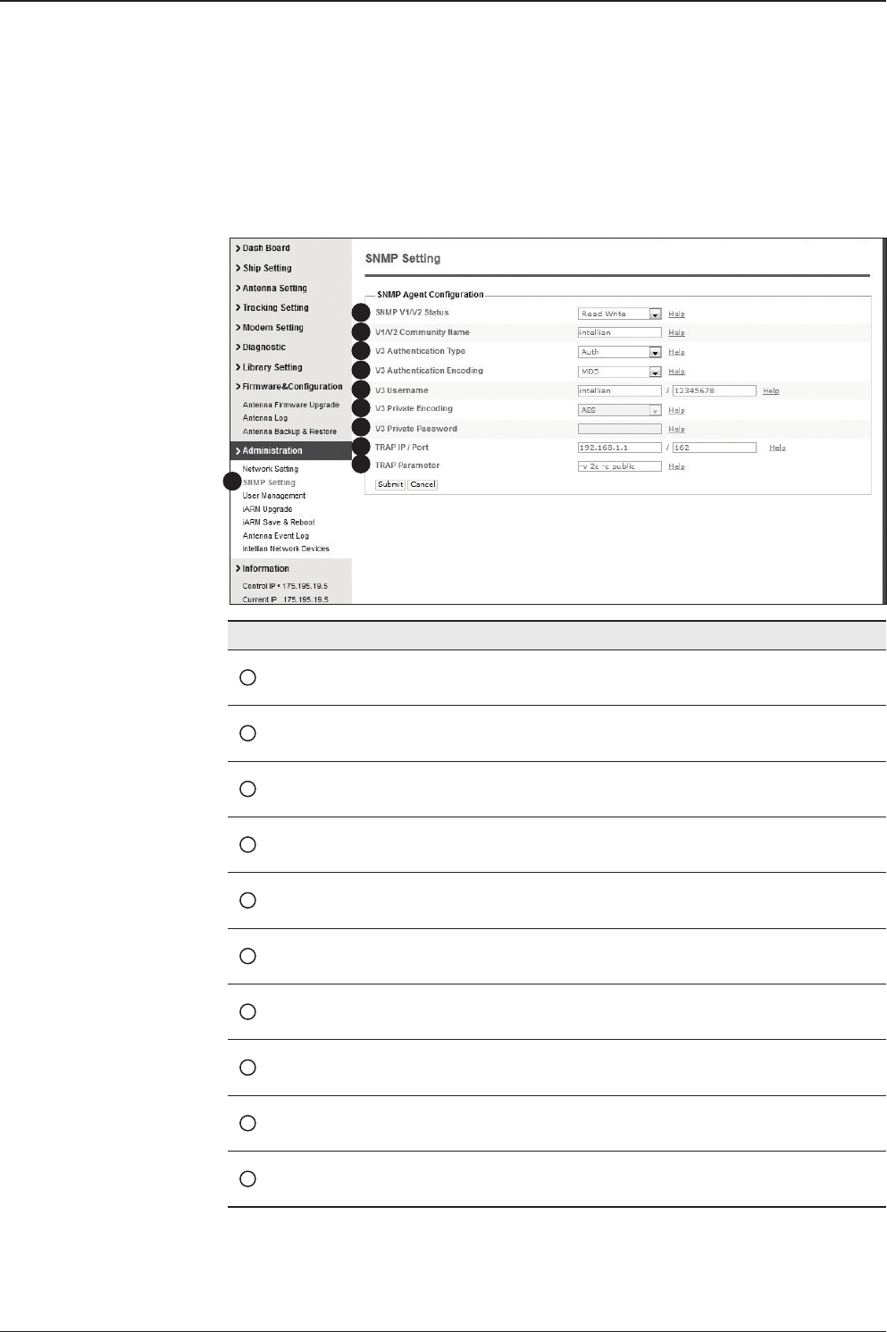
v130 – Marine Satellite Communication System
132
SNMP Setting
No. Item Description
1SNMP Setting Display and Set SNMP conguration.
2SNMP V1/V2 Status Set SNMP mode(Use Attribution Disable, Read Only
or Read Write).
3V1/V2 Community Name Set SNMP V2 community name.
4V3 Authentication Type Set SNMP V3 authentication mode.
5V3 Authentication
Encoding Set SNMP V3 authentication encoding.
6V3 Username Set the V3 username and password of the SNMP
Agent. The password is at least 8 character string.
7V3 Private Encoding Set SNMP V3 Private Encoding.
8V3 Private Password Set the V3 password of the SNMP Agent. The
Password is at least character string.
9TRAP IP/Port Set the V3 password of the SNMP Agent. The
Password is at least character string.
10 TRAP Parameter Set the SNMP trap specic parameter.
1
3
4
5
6
7
8
9
10
2
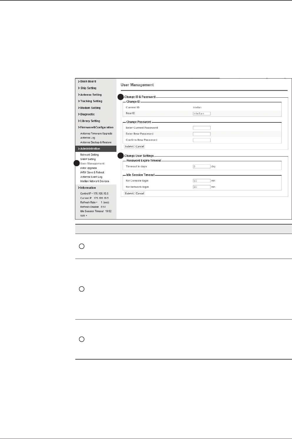
133
APTUS WEB
User Management
No. Item Description
1User Management
Change login ID and Password to access the Aptus Web.
This setting can be also accessed by ‘Account’ icon on the
top menu.
2Change ID
& Password
Change your login ID (user name) and password.
- Change ID : Enter your current login ID (user name) and
new login ID. Click the Submit button to validate the
changes that are made to the login ID.
- Change Password : Enter your current login password and
new login password. Click the Submit button to validate the
changes that are made to the login password.
3Change
User Settings
Change User Password Expire in days and Idle session timeout.
- Password Expire Timeout : Set password expire in days.
- Idle Session Timeout : Set for Console and for Network
Timeout.
1
3
2
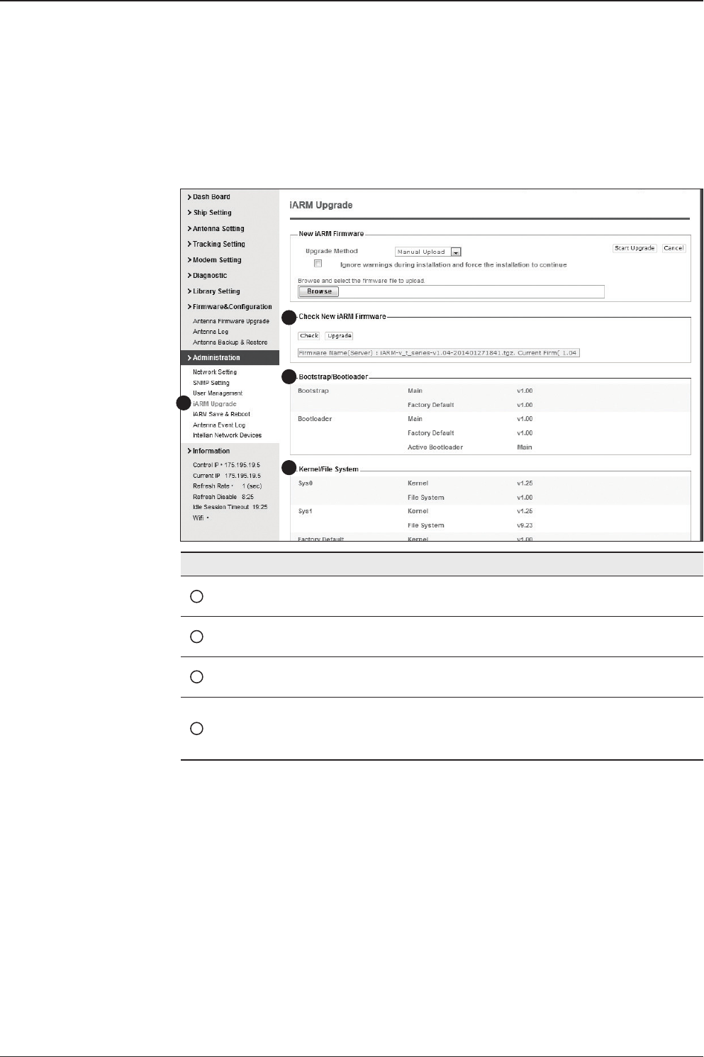
v130 – Marine Satellite Communication System
134
iARM Upgrade
No. Item Description
1iARM Upgrade Upgrade the rmware of iARM module.
2Check New
iARM Firmware Check new iARM rmware available on the server.
3Bootstrap
/Bootloader Displays current bootstrap and bootloader version.
4Kernel
/File System
ACU has 3 storage parts sys0, sys1, Factory Default.
Display kernel and le system version and current activated
part Information.
iARM rmware upgrade procedures:
1. Click on “Browse” button to select the iARM rmware le (.tgz) that you
wish to upgrade.
2. Click on “Start Update” button to update the iARM rmware. Wait until
the page is loaded.
3. It’ll inform you that the rmware is being uploaded.
1
3
4
2
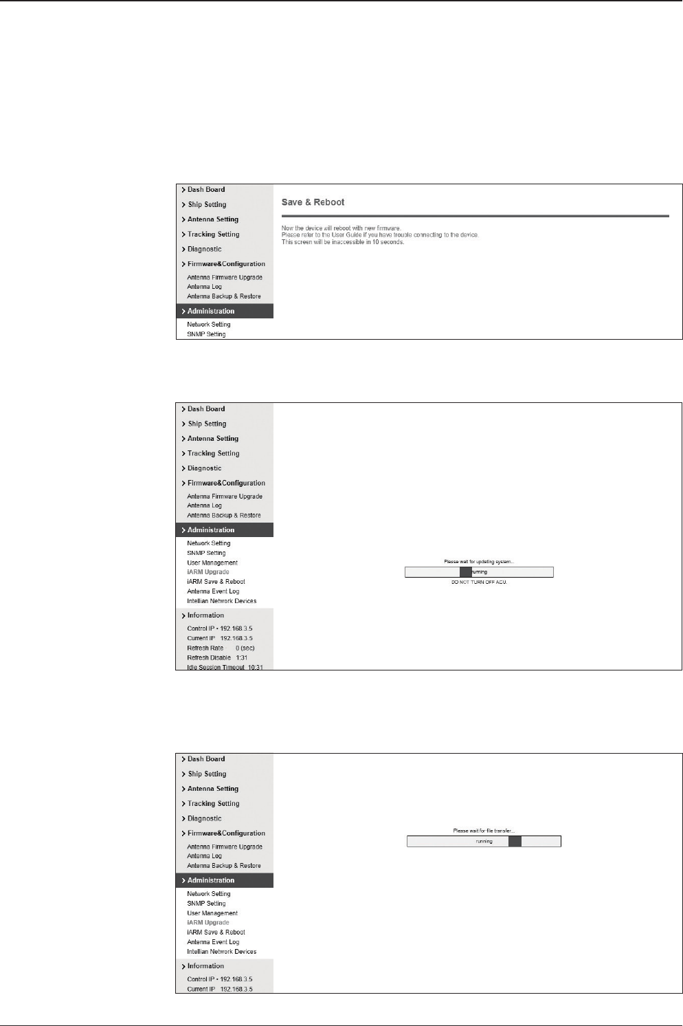
135
APTUS WEB
4. Do not turn off the ACU power if the rmware upgrade page is displayed.
5. It’ll take around 2 minutes to complete the rmware upgrade. Once the upgrade
is completed, the system will reboot automatically.
Firmware upload in
progress
Firmware upgrade in
progress
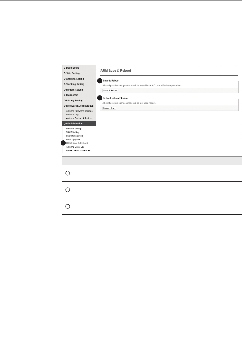
v130 – Marine Satellite Communication System
136
iARM Save & Reboot
No. Item Description
1iARM
Save & Reboot
Save settings to the ACU and reboot or reboot the system
without saving.
2Save & Reboot Save the modied settings and reboot the system.
Click Save & Reboot button.
3Reboot without
Saving
Reboot the system without saving the modied settings.
Click Reboot Only button.
1
3
2
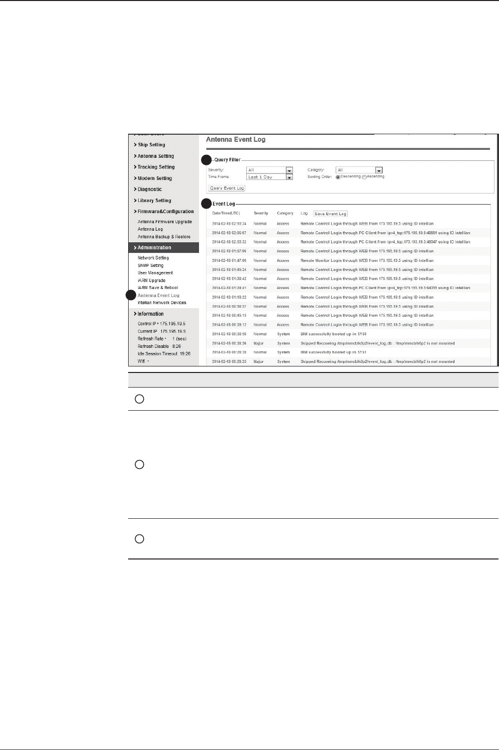
137
APTUS WEB
Antenna Event Log
No. Item Description
1Antenna Event Log Displays user's log information (Data/Time, Login ID and IP)
2Query Filter
Set the Log message option.
- Severity : Set urgency level.
- Category : Set target that caused the message.
- Time Frame : Set time limit that you want to show.
- Sorting Order : Sorting based on date
(descending or ascending).
3Event Log Displays log information (Date/Time, Severity, Category, Log).
- Save Event Log : Save log message to your PC.
1
2
3
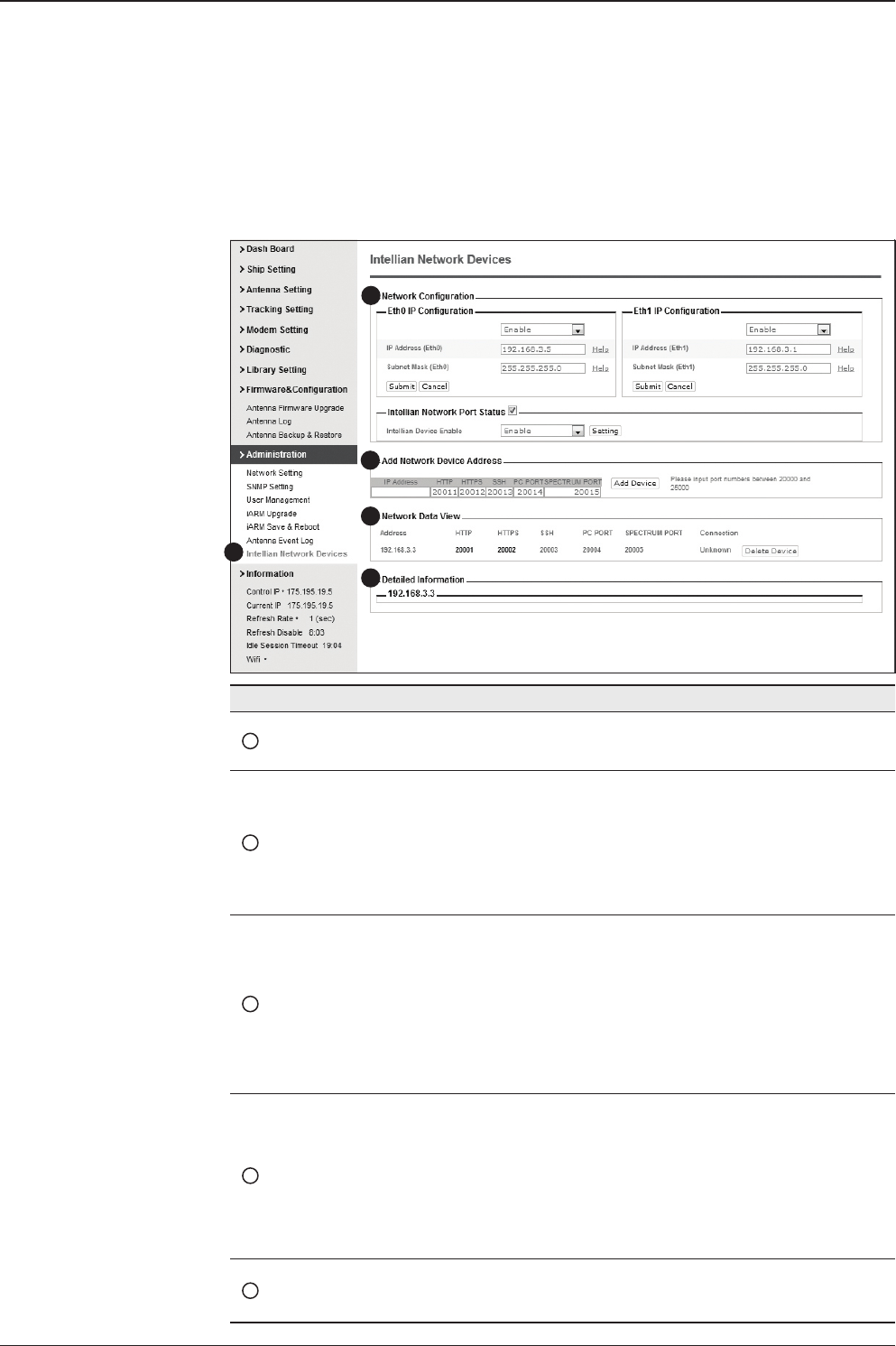
v130 – Marine Satellite Communication System
138
Intellian Network Devices
1
3
4
5
2
No. Item Description
1Intellian Network
Devices
Add up to 8 network devices and enable to monitor real time
information of the connected device.
2Network
Conguration
• Eth0 IP Conguration : ACU network Eth0 IP and subnet
mask setting.
• Eth1 IP Conguration : ACU network Eth1 IP and subnet
mask setting.
• Intellian Network Port Status : not used on t-series.
3Add Network Device
Address
Add Intellian network devices, then you can browse the
various information of the device.
• IP Address : IP address of the device to be monitored.
• HTTP, HTTPS, SSH : Set port number(These port
numbers will be matched the http, https or SSH port
number of each device).
4Network Data View
Displays the setting information of the added device
(IP address, http, https, SSH port number, current
connection).
If you click the http/https port number of each device,
then you can connect to the device’s web page.
If you click Delete Device button, then you can’t see its
information.
5Detailed Information Displays the information of each device. (Updated every 3
second).

139
This product is guaranteed by Intellian Technologies, Inc. against defect due to
faulty workmanship or materials and this guarantee covers for 3 year’s parts and 1
year workmanship guarantee from installation.
You are requested to present a copy of the purchase receipt that proves the date
of purchase for after sales service under warranty. In case of failure to present
the date of purchase, the warranty period is to be calculated to 30 days after the
manufacturing production date.
If you discover a defect, Intellian Technologies, Inc. will, at its option, repair, replace
or refund the purchase price of the product at no charge to you, provided you return
it during the warranty period, transportation charges prepaid, to the factory direct.
Please attach your name, address, telephone number, a description of the problem
and a copy of the bill of sale or sales receipt as proof of date of original purchase, to
each product returned to warranty service. Alternatively, you may bring the product
to an authorized Intellian Technologies, Inc. dealer/distributor for repair.
This Limited Warranty does not apply if the product has been damaged by accident,
abuse, misuse or misapplication or has been modied without the written permission
of Intellian Technologies, Inc.; if any Intellian Technologies, Inc. serial number has
been removed or defaced; or if any factory-sealed part of the system has been
opened without authorization.
Warranty
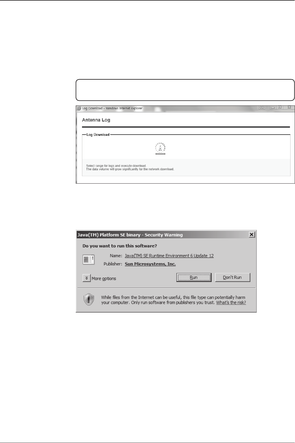
v130 – Marine Satellite Communication System
140
Appendix: Java Download and Install Guide
NOTE: To run Java applications you must have Java Runtime Environment (JRE)
version 6.0 and above installed in your PC/laptop.
If JRE has not been installed in your PC/laptop, you’ll get the below message box.
Click Run button to install it through online or ofine download and install methods.
After installing JRE, Java Applet will be executed automatically when you access
the Antenna Log page.
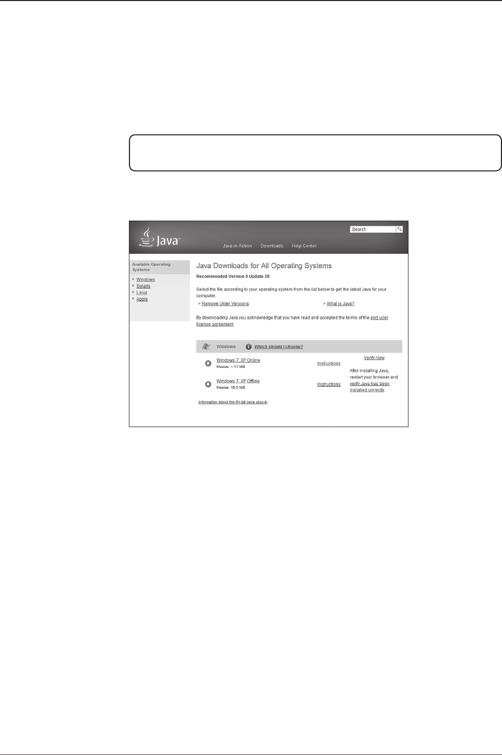
141
Appendix
NOTE: The JRE installation guide may vary depending on the operating system
installed in your PC/laptop.
Method 1. Online method for downloading and installing
http://www.java.com/en/download/manual.jsp

v130 – Marine Satellite Communication System
142
Method 2. Ofine method for downloading and installing
http://www.java.com/en/download/help/windows_ofine_download.xml
This process requires you to download an executable le that includes all the les
needed for the complete installation. You do not need to remain connected to the
Internet during the installation. The le can also be copied to a computer that is
not connected to the Internet.
1. Go to the Manual download page
2. Click on Windows Ofine.
3. The File Download dialog box appears prompting you to run or save the down-
load le. Click Save to download the le to your local system.
Tip: Save the le to a known location on your computer, for example, to your desktop.
4. Close all applications including the browser.
5. Double-click on the saved le to start the installation process.
6. The installation process starts. Click the Install button to accept the license
terms and to continue with the installation.
7. Oracle has partnered with companies that offer various products. The installer
may present you with option to install these programs when you install Java. After
ensuring that the desired programs are selected, click the Next button to continue
the installation.
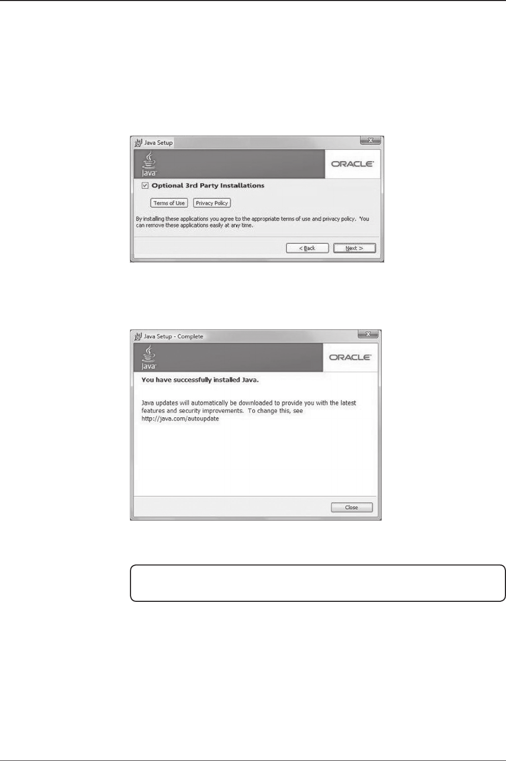
143
Appendix
8. A few brief dialogs conrm the last steps of the installation process: click Close
button on the last dialog.
9. This will complete Java installation process.
NOTE: You may need to restart (close and re-open) your browser to enable the java
installation in your browser.

v130 – Marine Satellite Communication System
144
Technical Specication
General
Approvals
CE – conforms to EU Directive 89/336/EEC
FCC – veried to CFR47: Part 15
Dimensions
Satellite Antenna Unit 165.2 x 168.9 cm
(65” x 66.5”)
Antenna Dish Diameter 125 cm (49.2”)
Antenna Control Unit 43.1 x 38.1 x 4.4 cm (17” x 15” x 1.7”)
Weight
Satellite Antenna Unit 149.7 kg (337 lbs)
Antenna Control Unit 3.5 kg (7.7 lbs)
Antenna System Performance
TX Frequency 14.0 ~ 14.5 GHz Ku-band
TX Gain 43.2 dBi
RX Frequency 10.95 ~ 12.75 GHz Ku-band
RX Gain 42.1 dBi
Polarized Feed Cross-pol or Co-pol
LNB pol Control Automatic LNB pol-angle Control
Azimuth Range Unlimited
Elevation Range -20° ~ +120°
Cross-level Range ± 37°
Stabilization Accuracy 0.2° peak mis-pointing @ max ship motion condition
Max Ship’s Motion ±25° roll, ±15° pitch, ±8° yaw @ 6 sec
Turning Rate Up to 12°/ sec & 5°/ sec2
BUC 4W, 8W (optional)
Rack Mount Antenna Control Unit
Display 2 Line 40 Character Graphic VFD Module
Serial Interface RS232C (19200 bps 8, N, 1) / USB
Modem Interface Ethernet port / RS232C / I/O ports
Remote Access RJ45, TCP/IP
Input Power 100~240 V AC, 50~60 Hz
(Max 350W including 8W BUC Power)
Gyrocompass Interface NMEA2000 / NMEA0183

145
Environment Specication
Specication Intellian Standards
1. Temperature Relative Humidity = Max. 55%
-40°C to 80°C
2. Damp Heat Humidity => 95%
25°C to 55°C
3. Vibration
1. DNV Resonance Search (X, Y, Z axis)
- 2 to 13.2Hz : Displacement 3mm
- 13.2 to 50Hz : Acceleration 2.1g
2. DNV Resonance Durability (X, Y, Z axis)
- 10Hz (Displacement 3mm)
: 90min (If no resonance fq)
- Highest resonance frequency
: 90 min (If Amp factor < 2)
- All each resonance frequencies
: 90 min (If Amp factor >= 2)
4. Shock
1. Operational Shock
- 15g at 11ms (half sine) on X, Y, Z axis
- 1,000 times per each +/- direction, total 6,000 times
2. Survival Shock
- 27g at 11ms (half sine) on X, Y, Z axis
- 10 times per each +/- direction, total 60 times
5. Water Ingress Resistant to water penetration sprayed from any direction
Standard: IPX6
6. Salt Mist Saline solution : 5 ±1 % NaCl
Storage period: 7 Days

v130 – Marine Satellite Communication System
146
www.intelliantech.com
info@intelliantech.com
APAC
Headquarters
Intellian Technologies, Inc.
348-5 Chungho-Ri, Jinwi-Myeon
Pyeongtaek-Si, Gyunggi-Do 451-862 Korea
T +82 31 379 1000 F +82 31 377 6185
Seoul Ofce
Intellian Technologies, Inc.
2F Dongik Building, 98 Nonhyun-Dong
Gangnam-Gu, Seoul 135-010 Korea
T +82 2 511 2244 F +82 2 511 2235
Maritime Technical Center
Busan Ofce
Intellian Technologies, Inc.
#1701,60, Centum buk-daero,
Haeundae-gu, Busan 612-050 Korea
T +82 51 746 9695 F +82 51 746 9440
Americas
Irvine Ofce
Intellian Technologies USA, Inc.
9004 Research Drive
Irvine, CA 92618 USA
T 949 727 4498 F 949 271 4183
EMEA
Rotterdam Ofce
Intellian B.V.
Bristolstraat 1, 3047AB
Rotterdam, The Netherlands
T +31 1 0820 8655 F +31 1 0820 8656
Tech Support: SupportAPAC@intelliantech.com
Tech Support: SupportAMERICAS@intelliantech.com
Tech Support: SupportEMEA@intelliantech.com
Southampton Ofce
Intellian Ltd.
Epsilon House, Enterprise Road, Southampton Science Park,
Southampton, Hampshire SO16 7NS, United Kingdom
T +44 2380 019 021 F +44 2380 767 092
Fort Lauderdale Ofce
Intellian Technologies USA, Inc.
2008 Marine Mile Blvd, Suite 108
Fort Lauderdale, FL 33312 USA
T 949 727 4498 F 949 271 4183
