V130 Manual
2017-12-08
: Intellian V130 Manual v130_Manual v130 d
Open the PDF directly: View PDF ![]() .
.
Page Count: 119 [warning: Documents this large are best viewed by clicking the View PDF Link!]

Marine Satellite Communication Antenna System
v130
Installation and Operation Manual

Serial number of the product
This serial number will be required for the all troubleshooting or service inquiries.
© 2013 Intellian Technologies Inc. All rights reserved. Intellian and the Intellian
logo are trademarks of Intellian Technologies, Inc., registered in the U.S. and other
countries. The v-Series and the v130 are trademarks of Intellian Technologies,
Inc. Intellian may have patents, patent applications, trademarks, copyrights,
or other intellectual property rights covering subject matter in this document.
Except as expressly provided in any written license agreement from Intellian,
the furnishing of this document does not give you any license to these patents,
trademarks, copyrights, or other intellectual property.
All other logos, trademarks, and registered trademarks are the property of their
respective owners. Information in this document is subject to change without
notice.
Every effort has been made to ensure that the information in this manual is
accurate. Intellian is not responsible for printing or clerical errors.
Doc. No. 2013PQ-UM0322-V1_1

INDEX

5
INDEX
CERTIFICATIONS
INTRODUCTION
Introduction to Intellian v130 9
Features of Intellian v130 10
System Congurations 11
INSTALLING THE ANTENNA
System Package 14
Planning the Installation 19
Antenna Installation 22
INSTALLING THE ACU
Mounting the ACU 34
Ship Gyro Connection 36
OPERATING THE ACU
Introduction 40
Normal Mode 41
Setup Mode 44
Installation Settings 45
Antenna Settings 48
Satellite Settings 59
System Settings 66
PC CONTROLLER SOFTWARE
Introduction 76
PC to ACU Communication Setup 77
Main Menu 79
Controller Menus 81
REMOTE WEB ACCESS
Introduction 88
Main Page 89
Antenna Settings 91
Antenna/ACU Firmware Upgrade 105
Ethernet to Serial Settings 109
WARRANTY 117
TECHNICAL SPECIFICATION 118

CERTIFICATIONS
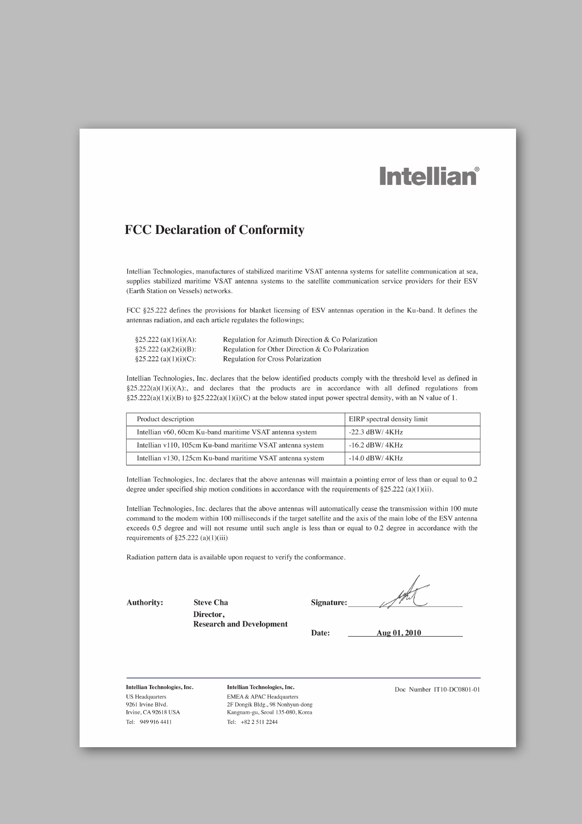

v130 – Marine Satellite Communication System
8
Introduction to Intellian v130
Features of Intellian v130
System Congurations
INTRODUCTION

9
INTRODUCTION
Introduction to Intellian v130
Intellian v130 (1.25m) is a ku-band VSAT maritime antenna system that supports
SCPC, TDMA, Spread Spectrum or Carrier-in-Carrier and is suitable for high-speed
internet, email, le transfer, video conference, VoIP, VPNs and database backup.
With its 3-axis stabilized platform and advanced shock-resistant and vibration
damping design, the v130 is capable of withstanding the most demanding sea
conditions to provide “always on” and “high-quality” broadband communications
on all types of vessels.
The v130 is built to meet or exceed the industry’s most stringent standards such as
FCC, ETSI, R&TT, and MIL-STD-167. The v130 offers superior RF performance with
its simple yet sophisticated design that reduces installation time and total cost of
ownership. Equipped with Remote IP access function, the v130 can be accessed,
monitored and controlled from anywhere and anytime to ensure cost-effective
technical supports without having an engineer come on board.
The v130 is fully integrated with ABS (Automatic Beam Switching) function with
leading service providers who use the embedded OpenAMIP protocol of the iDirect
platform and v130 is also compatible with various platforms such as Hughes,
Comtech, SatLink and more. The v130 is available in both cross-pol and co-pol
feeds and supports multi-band LNBs and the option of 4W-25W BUC.

v130 – Marine Satellite Communication System
10
Features of Intellian v130
Enjoy always-on broadband connection at sea
Intellian v130 is the most modern communication system that offers a high-
speed and always-on broadband connection at sea, where the atmospheric and
environmental conditions are very harsh.
Best solution for all kinds of vessels
The v130 is the best solution for all kinds of vessels that require the satellite
broadband connection around the globe. The major RF components are designed
and manufactured by Intellian’s solid in-house engineering to achieve superior
antenna gain and xpol isolation recognized among the best performances in the
industry.
Gyro-free satellite search capability
Intellian’s new generation gyro-free satellite search function enables the v130 to
acquire and lock onto the satellite without requiring a separate input from the ship’s
gyrocompass
Wide elevation range
The v130 have a wide elevation range from -15° to 120° and -20° to 120°,
respectively which offer seamless signal reception while the vessel is traveling near
the Equator or Polar Regions.
Remote management solution
The v130 can be accessed, monitored, and controlled from any location in the world
through the embedded web server, which can save tremendous time and cost from
the hundreds of routine maintenance activities. These solutions include operating
rmware upgrade, tracking parameters resets and system diagnostic.
Save installation and maintenance time
Simple design allows users to install and setup the system without the need for a
skilled engineer. The v130 provides the utmost in reliability resulting in time and cost
savings in maintenance.
Various platform compatibility
The v130 is fully integrated with Automatic Beam Switching (ABS) function with
leading service providers who use the embedded OpenAMIP protocol of the iDirect
platform and ROSS ROAM protocol of the Comtech platform. The v130 is also
compatible with various platforms such as Hughes, Comtech, SatLink and more.
11
INTRODUCTION
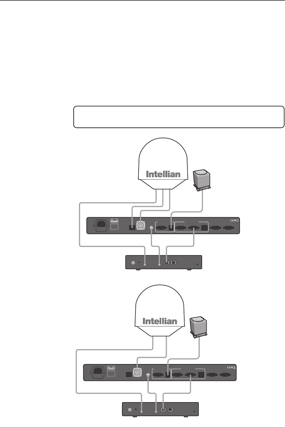
System Congurations
For your satellite communication system to work properly, the system will have to
be connected with all of the provided components properly, as shown in the gure
below. Separate purchase of a satellite modem, ship’s gyrocompass, and Intellian
Dual VSAT Mediator are required.
Basic System
Conguration
(8W BUC)
Basic System
Conguration
(4W BUC)
MODEM Interface
Gyro-Compass Input
RS-232/RS-422
Antenna Rx
24 V == 5 A
BUC
Power Modem Rx
Satellite Modem
(Not supplied)
Antenna Control Unit
Modem InterfaceModem RX
Antenna TX
Antenna RX
BUC
Power
AC 100 ~ 240 V
(50~60 Hz 4A)
Ship’s Gyrocompass
(Not supplied)
PC Interface Tx
ANT1RS232 USB ANT2 MODEM
Rx
ANT1 ANT2 MODEM
ACU Interface
ACU1RS232 & RS422Console ACU
Modem Interface
Ethernet
NMEA
Heading
+ -
MODEM Interface
Gyro-Compass Input
RS-232/RS-422
Antenna Rx
24 V == 5 A
BUC
Power Modem Rx
MODEM Interface
Gyro-Compass Input
RS-232/RS-422
Antenna Rx
24 V == 5 A
BUC
Power Modem Rx
BUC
Power
BUC
Power
RX1 TX1 TX2
Antenna
Unit 1
Antenna
Unit 2
RX2
AC 100 ~ 240V (50~60Hz)
Antenna Control Unit 1
Satellite Modem
Antenna Control Unit 2
Mediator
Ship’s
Gyrocompass
TX RX Interface
PC
NOTE: BUC power should set to ON from the modem when you connect to a 4W
BUC. BUC power should set to OFF from the modem when you connect to an 8W
BUC.
MODEM Interface
Gyro-Compass Input
RS-232/RS-422
Antenna Rx
24 V == 5 A
BUC
Power Modem Rx
Satellite Modem
(Not supplied)
Antenna Control Unit
Modem InterfaceModem RX
Antenna TX
Antenna RX
AC 100 ~ 240 V
(50~60 Hz 4A)
Ship’s Gyrocompass
(Not supplied)
PC Interface Tx
ANT1RS232 USB ANT2 MODEM
Rx
ANT1 ANT2 MODEM
ACU Interface
ACU1RS232 & RS422Console ACU
Modem Interface
Ethernet
NMEA
Heading
+ -
MODEM Interface
Gyro-Compass Input
RS-232/RS-422
Antenna Rx
24 V == 5 A
BUC
Power Modem Rx
MODEM Interface
Gyro-Compass Input
RS-232/RS-422
Antenna Rx
24 V == 5 A
BUC
Power Modem Rx
BUC
Power
BUC
Power
RX1 TX1 TX2
Antenna
Unit 1
Antenna
Unit 2
RX2
AC 100 ~ 240V (50~60Hz)
Antenna Control Unit 1
Satellite Modem
Antenna Control Unit 2
Mediator
Ship’s
Gyrocompass
TX RX Interface
PC
v130 – Marine Satellite Communication System
12
MODEM Interface
Gyro-Compass Input
RS-232/RS-422
Antenna Rx
24 V == 5 A
BUC
Power Modem Rx
Satellite Modem
(Not supplied)
Antenna Control Unit
Modem InterfaceModem RX
Antenna TX
Antenna RX
BUC
Power
AC 100 ~ 240 V
(50~60 Hz 4A)
Ship’s Gyrocompass
(Not supplied)
PC Interface Tx
ANT1RS232 USB ANT2 MODEM
Rx
ANT1 ANT2 MODEM
ACU Interface
ACU1RS232 & RS422Console ACU
Modem Interface
Ethernet
NMEA
Heading
+ -
MODEM Interface
Gyro-Compass Input
RS-232/RS-422
Antenna Rx
24 V == 5 A
BUC
Power Modem Rx
MODEM Interface
Gyro-Compass Input
RS-232/RS-422
Antenna Rx
24 V == 5 A
BUC
Power Modem Rx
BUC
Power
BUC
Power
RX1 TX1 TX2
Antenna
Unit 1
Antenna
Unit 2
RX2
AC 100 ~ 240V (50~60Hz)
Antenna Control Unit 1
Satellite Modem
Antenna Control Unit 2
Mediator
Ship’s
Gyrocompass
TX RX Interface
PC
Dual System
Conguration
(8W BUC)

13
INTRODUCTION
INSTALLING THE ANTENNA
System Package
Antenna Unit
ACU (Antenna Control Unit)
Installation Kit
Planning the Installation
Selection of Antenna Installation Site
Congure Radiation Hazard/Blockage Zones
System Cables
Power Requirement
Tools Required for Installation
Antenna Installation
Unpacking the Wooden Crate
Antenna Dimensions
Antenna Mounting Templates
Position the Radome
Mount the Radome
RF Cable Connections
Secure the RF Cables

v130 – Marine Satellite Communication System
14
System Package
The package of Intellian v130 consists of antenna unit, ACU and installation kit box.
Antenna unit
ACU
Installation kit box

15
INSTALLING THE ANTENNA
Antenna Unit
The antenna unit includes an antenna pedestal inside a radome assembly unit. The
pedestal consists of a satellite antenna main dish with RF components mounted
on a stabilized pedestal. The radome protects the antenna pedestal assembly unit
from the marine environment.
Antenna Unit
v130 – Marine Satellite Communication System
16
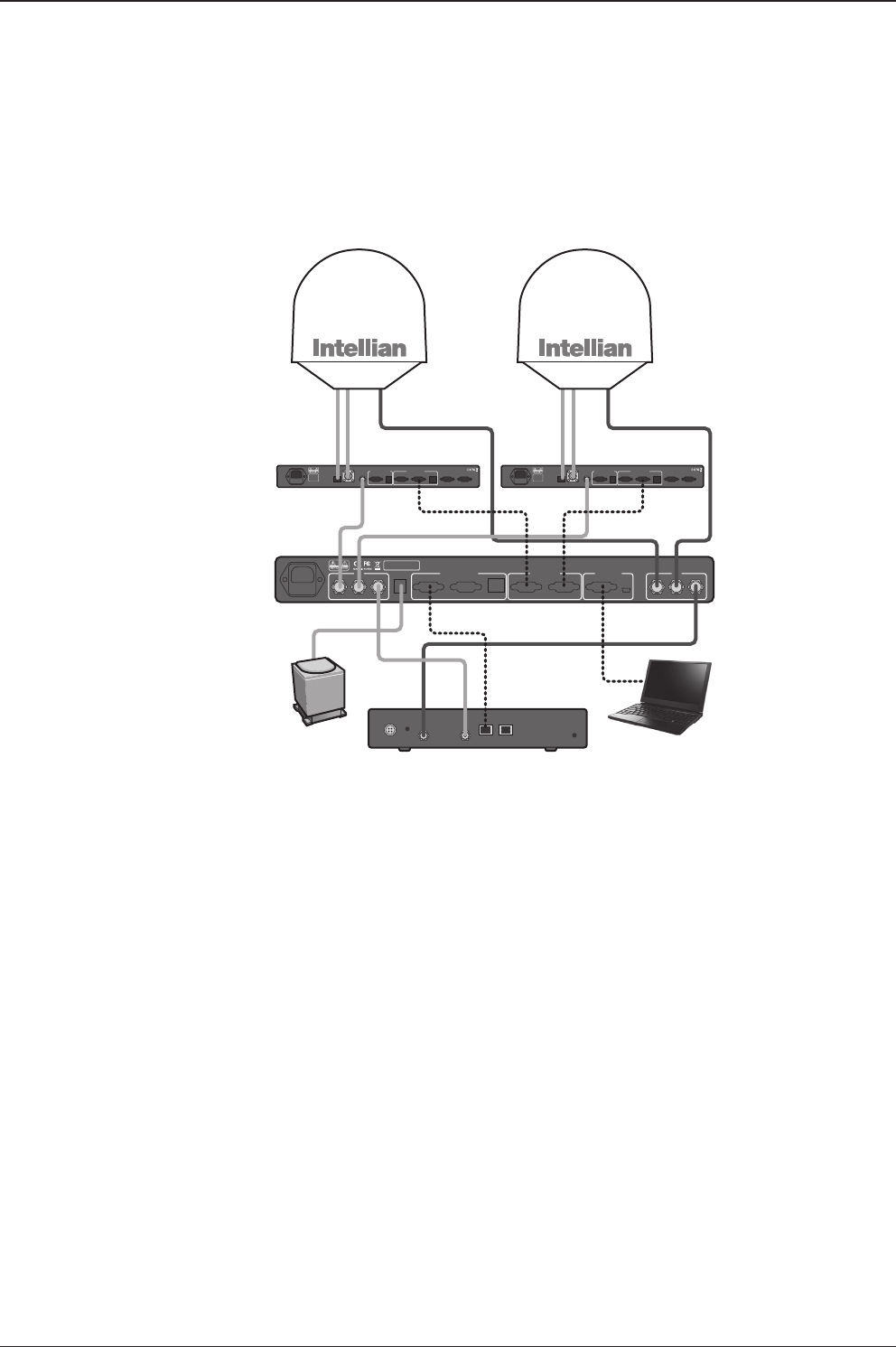
ACU (Antenna Control Unit)
ACU provides power to the antenna and Block Up Converter (BUC), The digital
Vacuum Fluorescent Display (VFD) allows for easy operation of the ACU, even in
the dark.
The functions of the ACU are as follows:
• System startup
• Setting the satellite
• Editing satellite information
• Setting the antenna parameter
• Setting the antenna manual search
• Setting the LNB local frequency
• Setting radiation hazard or blockage zone
• Setting modem connections
• Setting GPS and Gyrocompass
• Display versions
• Display power status
• Performing diagnostic tests
• Backup and restore the system settings
• Set up the interface with a PC
Antenna Control Unit
Front panel
Rear panel
17
INSTALLING THE ANTENNA
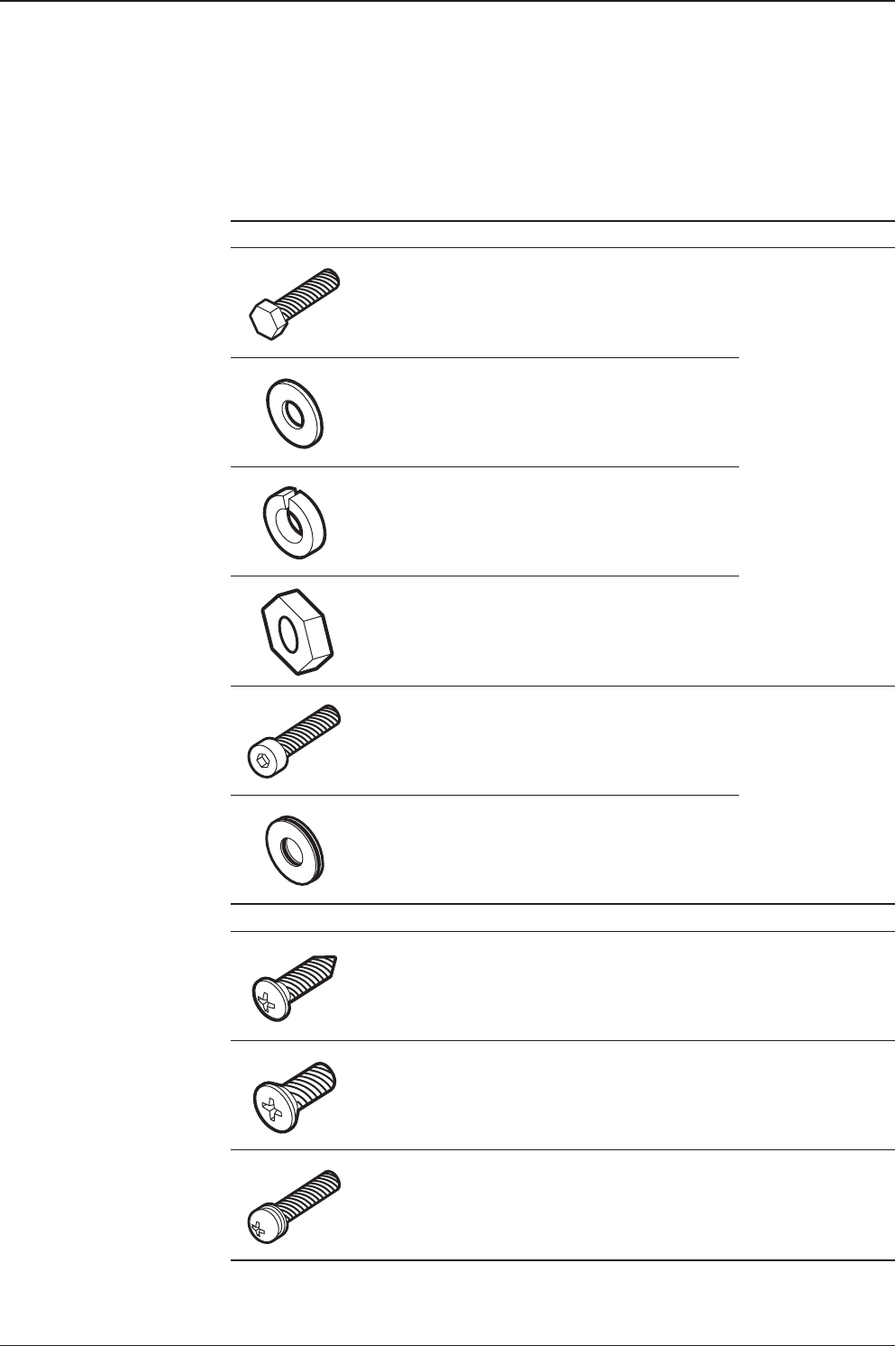
Antenna Q’ty Description Size Remark
5Hex. Bolt M12 x 80L
Antenna-Deck
4 Sets: Installation
1 Set: Spare
5Flat Washer M12
5Spring Washer M12
10 Hex. Nut M12
5Hex Head Wrench
Bolt M6 x 40L
Radome
(Spare Blots)
5Dome Washer M6
ACU Q’ty Description Size Remark
5Self-Tapping
Screw 4 x 16 Table Mount
Bracket
10 Flat Head Screw M3 x 8L Rack Mount
Bracket ACU
5Sems Bolt M3 x 12L Table Mount
Bracket ACU
Installation Kit
Contains the items required for securing the antenna unit and ACU to the vessel.
v130 – Marine Satellite Communication System
18
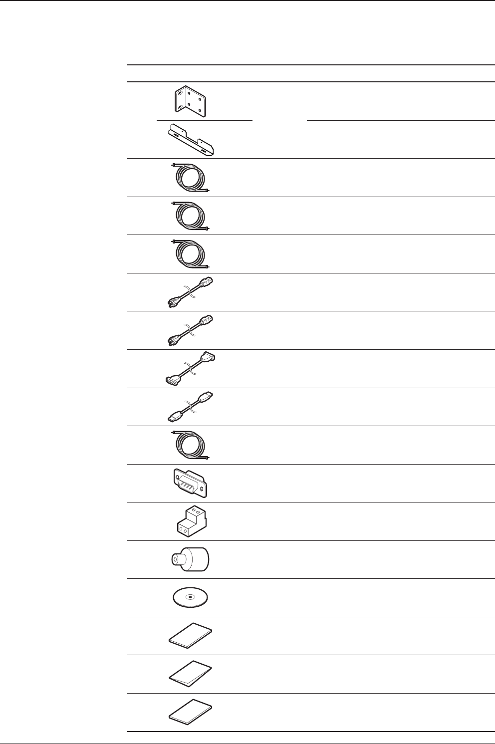
Other Components
Item Image Q’ty Description Size Remark
1
2
ACU
Bracket
Rack - ACU - 19 inch Rack
2Table - ACU-Table
2 1RG6 Cable 3 m ACU to Modem
3 2RG6 Cable
(Optional) 15 m Antenna to Modem &
Antenna to ACU
41BUC Power Cable 15 m Antenna to ACU
5 1AC Power Cord
(CEE7/7) 1.5 m ACU Power
6 1AC Power Cord
(USA) 1.8 m ACU Power
7 1PC Serial Cable 1.8 m ACU to PC
8 1USB Cable
(A-A / M-M) 1.8 m ACU to PC
9 1iDirect Interface Cable 1.5 m ACU to Modem
10 2D-Sub 9 Pin Male
Connector - ACU
11 1BUC Power Connector
(AK950-2) - Antenna (BUC In)
12 1N to F Adapter - N (Male) to F (Female)
Adapter
13 1Installation CD - -
14 1User Manual - -
15 1Mounting Template - -
16 1Wooden Crate
Unpacking Guide - -

19
INSTALLING THE ANTENNA
Planning the Installation
Selection of Antenna Installation Site
Install the antenna in accordance with the following procedures to insure maximum
performance of the antenna. The ideal antenna site has a clear view of the horizon
or satellite all around. Please be sure there are no obstacles within 15º above the
center of the antenna. Any obstacles can prevent the antenna from transmitting and
receiving the satellite signal.
Do not install the antenna near the radar especially on the same plane as its energy
levels may overload the antenna front-end circuits. It is recommended to position
the antenna at least 4 feet (1.2 m) above or below the level of the radar and minimum
of 15 feet (4.6 m) away from the high power short wave radars.
The mounting platform should be rigid enough and not subjected to excessive
vibration. The movement of the antenna can be minimized by installing at the
center of the vessel. If these conditions can be only partially satised, nd the best
compromised installation site between the various considerations.
Elevation Limit
of Obstacles
15°
Congure Radiation Hazard/Blockage Zones
It is important to setup the radiation hazard or blockage zones for Intellian VSAT
communication systems. The ACU can be programmed with relative azimuth and
elevation sectors to create up to ve zones where transmit power would endanger
personnel who are frequently in that area or blockage exists. Several things happen
when the antenna is within one of these zones.
1. “BLOCK” will be displayed on the ACU screen.
2. Tracking continues as long as the signal level is greater than the predened
threshold value. When the signal level drops below the threshold value the
antenna will wait “Search Wait Time” parameter amount of time and re-target the
satellite you targeted last. The antenna will continue to re-target the satellite until
the satellite is re-acquired and tracking can be resumed.
3. A transmit inhibit output from the ACU will disable/mute the modem transmission.
Antenna Unit Obstacle

v130 – Marine Satellite Communication System
20
System Cables
Before installing the system cables, you need to take the following points into
consideration.
1. All cables need to be well clamped and protected from physical damage and
exposure to heat and humidity.
2. Cable with an acute bend is not allowed.
3. Where a cable passes through an exposed bulkhead or deck head, a watertight
gland or swan neck tube should be used.
Power Requirement
Intellian v130 has been designed to work on a vessel’s power supply rated at 100-
240 V AC.
• BUC Power Cable
Cable Length mm2 per conductor
Up to 30 meters 1.25 mm2
Up to 50 meters 2.30 mm2
Up to 70 meters 3.00 mm2
Up to 120 meters 5.00 mm2
Recommended
BUC Power Cables
Type Multi-conductor, Shielded
Number of wires 5 conductors for Synchro
• Gyro Compass / GPS Interface Cable (Customer Furnished)
Recommended
Cables
• RF Cable (Customer Furnished)
Due to the voltage losses across the length of the RF coax on L-Band, Intellian
recommends the following 50 ohm coax cable types for standard system
installations. For cables that run longer than 150 meters, please consult Intellian
Technologies.
Recommended
RF Cables Coaxial Cable
Type
Attenuation in
dB/100M
Attenuation in
dB/M
Recommended
Cable Length
LMR300 30.3 0.303 35M
LMR400 19.6 0.196 60M
LMR500 15.9 0.159 80M
LMR600 12.8 0.128 100M
LMR900 8.6 0.086 150M
LMR1200 6.5 0.065 200M

21
INSTALLING THE ANTENNA
Power Drill
Phillips-Head Screwdriver
Flat Head Screwdriver
(min 5mm)
Tools Required for Installation
11 mm Spanner
19 mm Spanner
5 mm Allen/Hex key
v130 – Marine Satellite Communication System
22
Antenna Installation
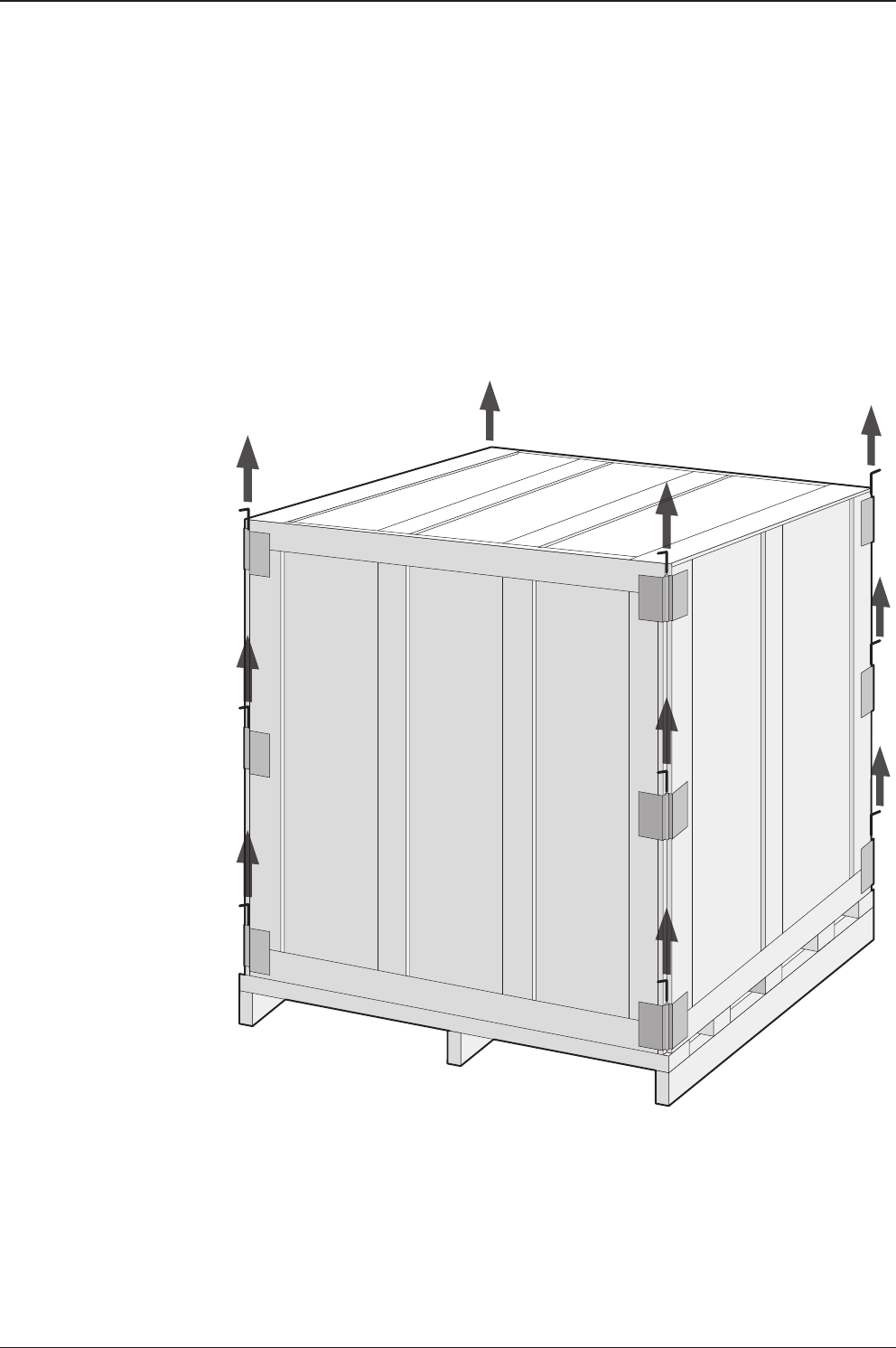
Unpacking the wooden crate of v130
Step 1.
Remove the top panel and 12 pins from the hinges of the wooden crate.
23
INSTALLING THE ANTENNA
Step 2.
Remove 8 tapping screws that mount the ACU box and installation kit box to the pallet.
v130 – Marine Satellite Communication System
24
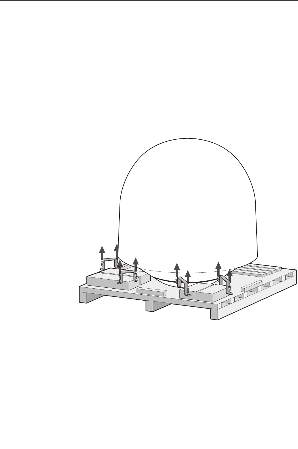
Step 3.
Lift the pallet by using a suitable size of lifting equipment.
Using a 19mm spanner, remove 4 shipping bolts that mount the antenna to the pallet.

25
INSTALLING THE ANTENNA
Step 5.
Remove the ratchet strap.
* The photo with the opened radome is only for display purpose.
Step 4.
Open the radome hatch.
Radome Hatch
Flat Head Screwdriver
(min 5mm)
v130 – Marine Satellite Communication System
26
Step 6.
Remove the tie wrap from the pedestal. Do not turn on the antenna power if the shipping
restraints from the antenna pedestal have not been removed completely.
27
INSTALLING THE ANTENNA
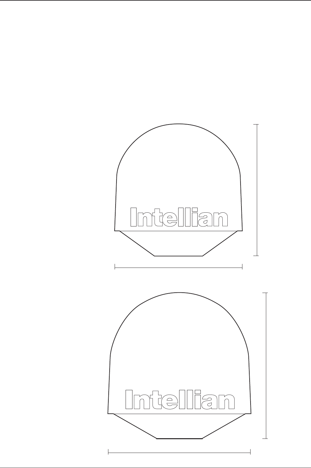
Antenna Dimensions
The method of installation and mounting of antenna may vary with vessel design
but the following procedures are applicable in most situations, and will result in a
secure and effective installation. Conrm the height and diameter of the antenna
before installing it.
147.4 cm (58")
152.2 cm (59.9")
168.9 cm (66.5")
165.2 cm (65")
v110
Radome Dimensions
v130
Radome Dimensions
v130 – Marine Satellite Communication System
28
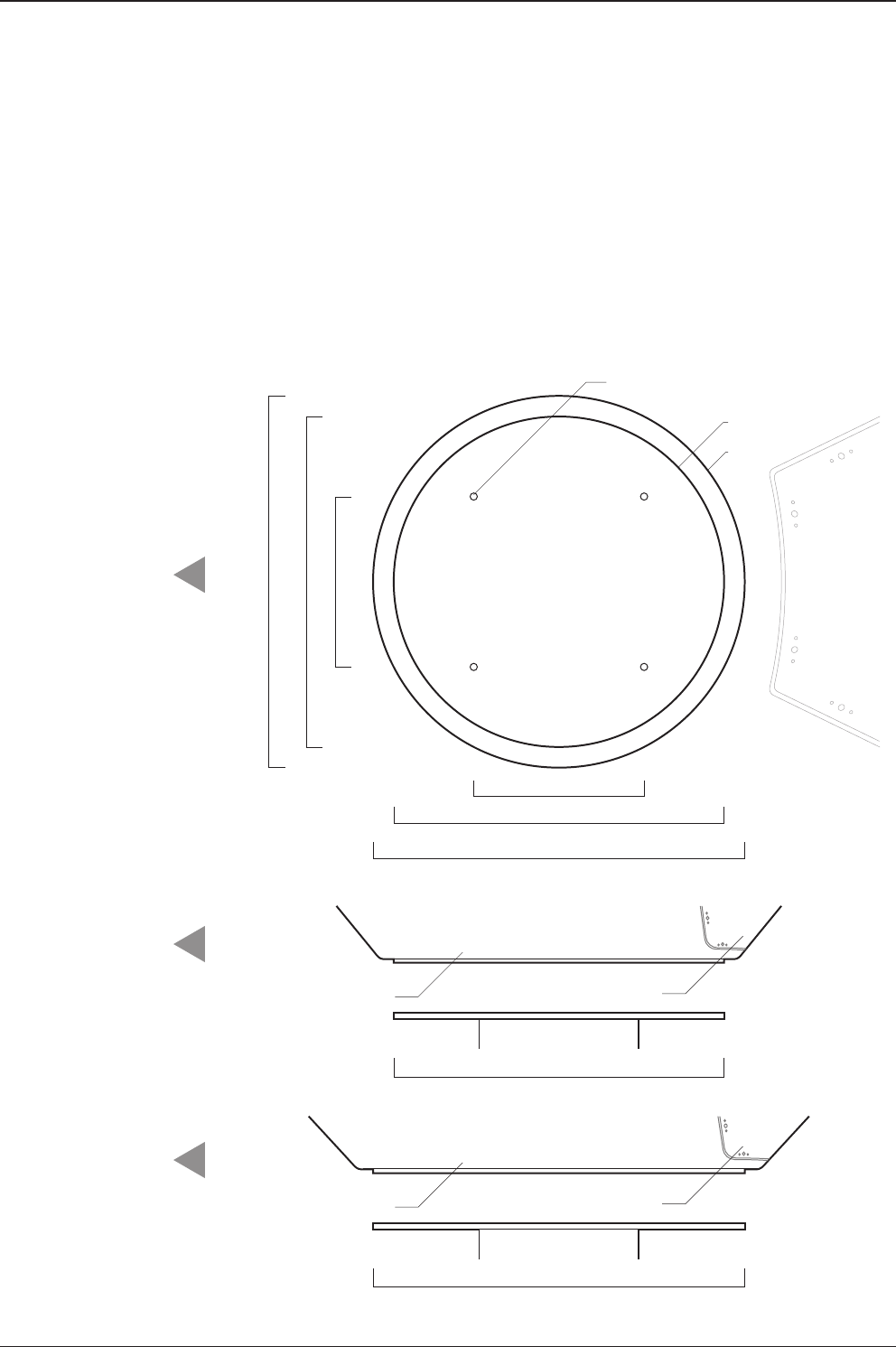
Ø48 cm (18.9")
Radome Hatch
24.75 cm (9.74")
v110 : Ø48 cm (18.9")
v130 : Ø54 cm (21.3")
v110 Radome Bottom
Ø54 cm (21.3")
Radome Hatch
v130 Radome Bottom
4-Ø13 mm(0.5") Holes
v110
v130
v110 : Ø48 cm (18.9")
v130 : Ø54 cm (21.3")
24.75 cm (9.74")
BOW direction
BOW direction
BOW direction
Antenna Mounting Templates
The mounting holes must be in the exact same place as shown in the diagram
below. The radome should be positioned with the Bow marker aligned as close
as possible to the centerline of the ship. Variation from actual alignment can be
compensated with the "BOW Adjust" settings in the ACU.

29
INSTALLING THE ANTENNA
Position the Radome
The radome should be positioned with the BOW marker aligned as closely as
possible to the ship’s centerline.
Mim. 120 cm (47”)
Mounting Plate
Min. 1 cm (0.4”)
Max. 3 cm (1.2”)
Support Pedestal
Appr. Ø25.4 cm (10”)
Recommended size of the
support pedestal
v130 – Marine Satellite Communication System
30
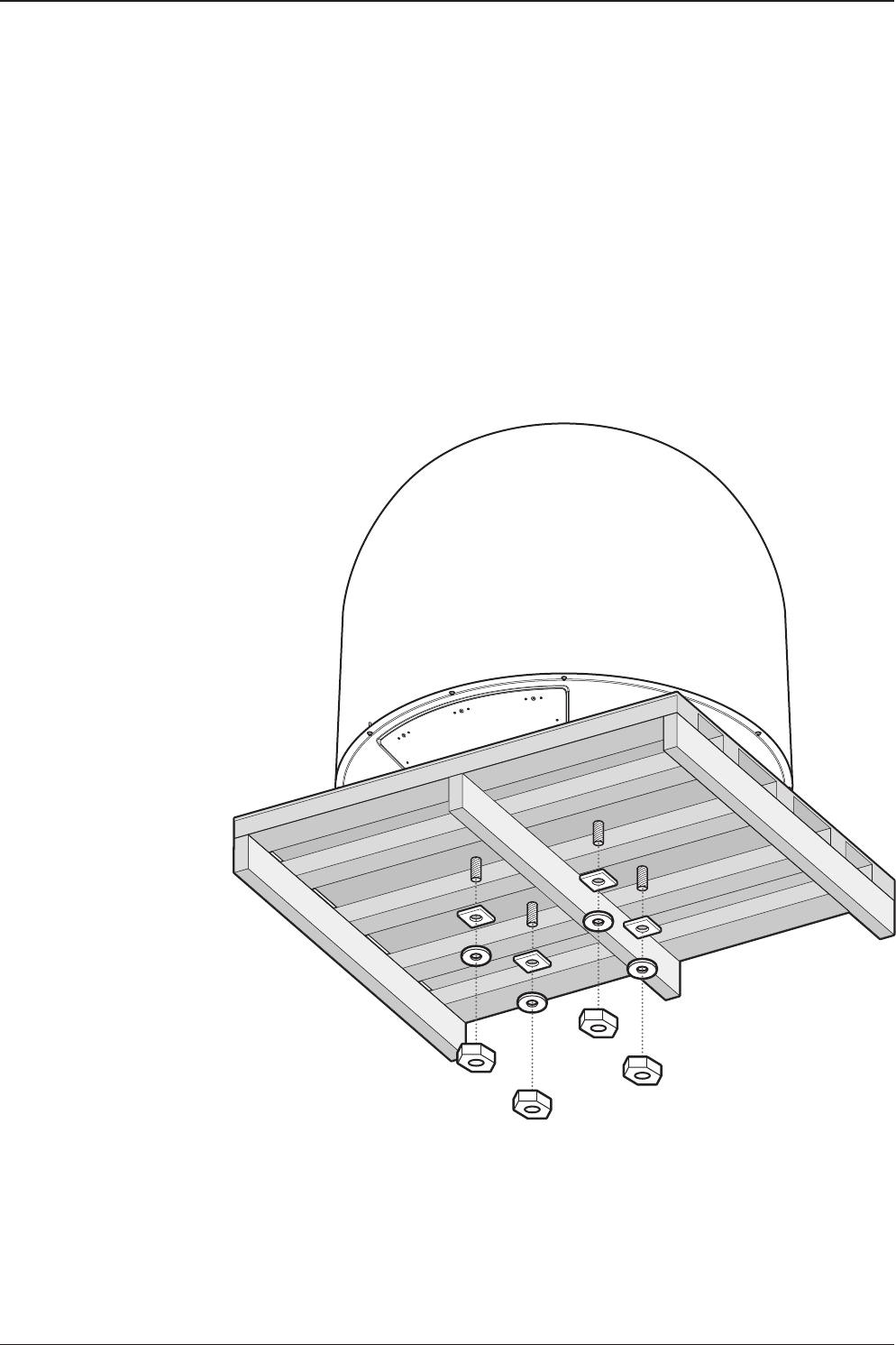
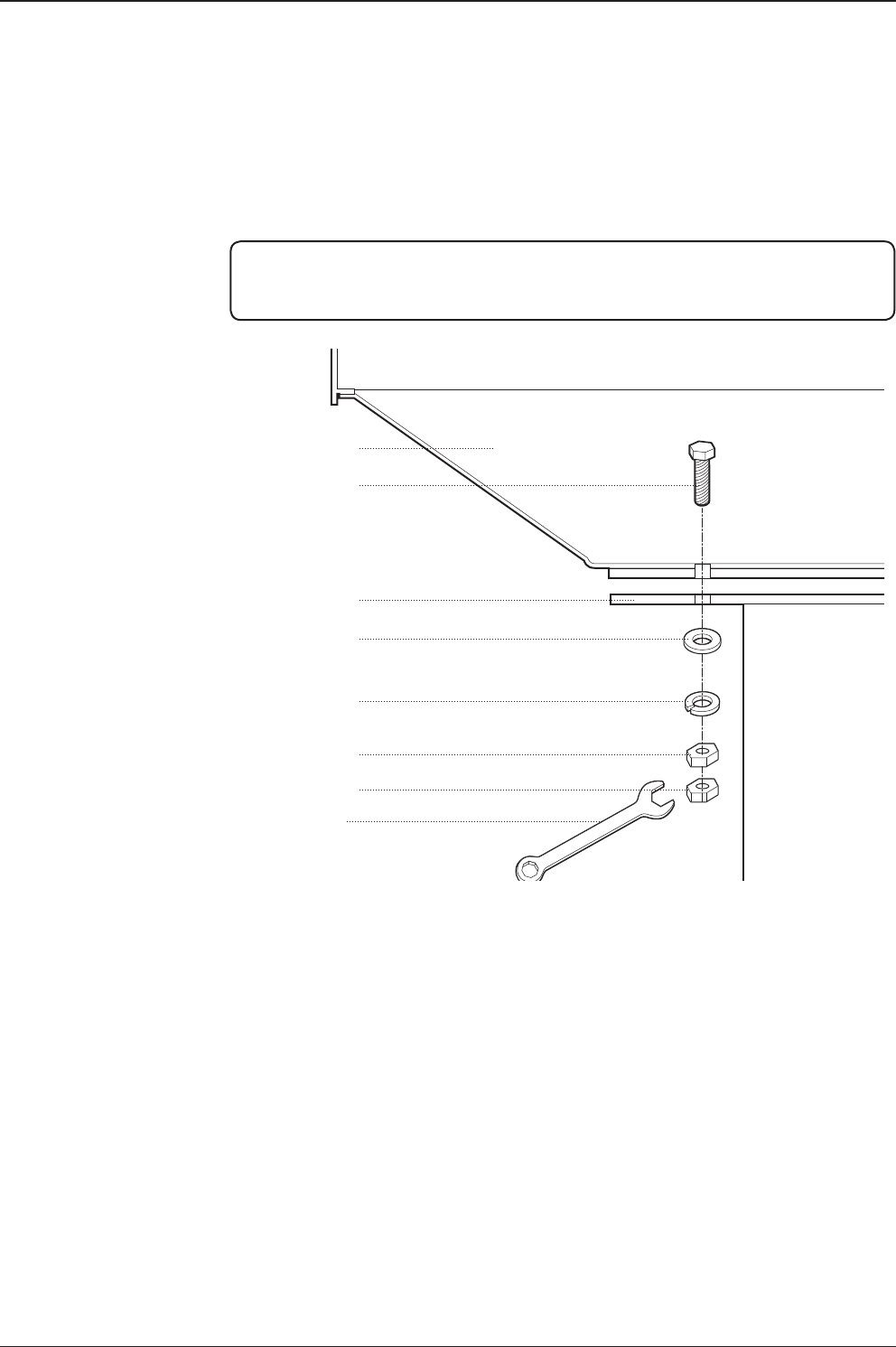
M12 Hex Bolt
Deck
Antenna Unit
M12 Flat Washer
M12 Spring Washer
M12 Hex Nut
M12 Hex Nut
19 mm Spanner
Mounting the Radome
Bolt the radome base directly to the support pedestal.
Note: Makesure to use the Intellian supplied blots from the accessory box when you
mount the radome. Apply Loctite #262 or equivalent to the bolt thread, and fasten it
with the tight torque of 110 N·m
31
INSTALLING THE ANTENNA
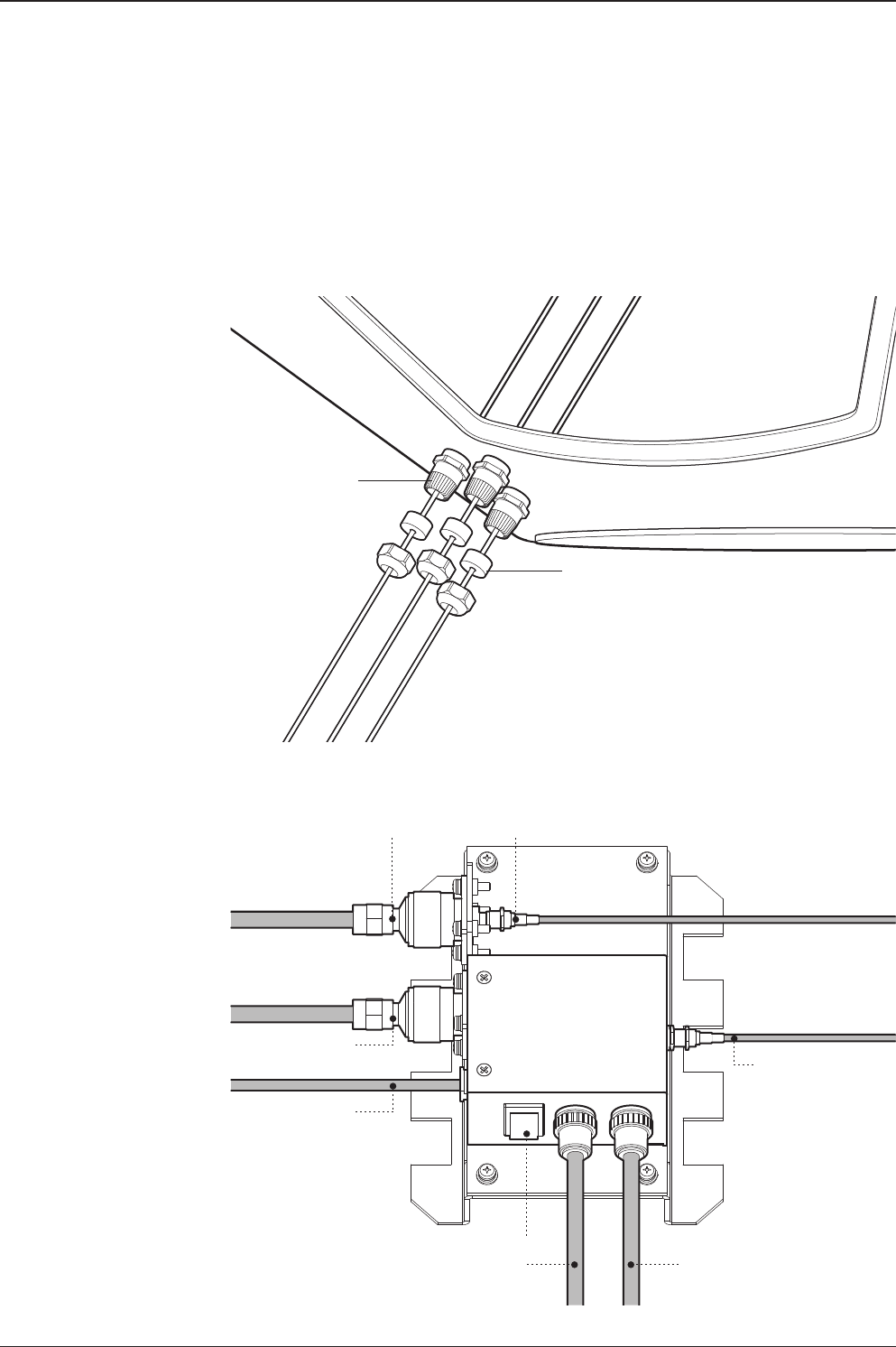
Modem Tx Cable
(from modem)
ACU Rx Cable
(from ACU)
On/Off Switch
BUC Power Cable
(from ACU)
Antenna Power Cable
(from antenna)
Rotary #2 Rx Cable
(from antenna)
BUC Power Cable
(from antenna)
Rotary #1 Tx Cable
(from antenna)
Power Switch Box
Shrinkage Guide
Rubber Gland
RF Cable Connections
Ensure that the switch on the power switch box is off during the installation period.
When all the cables have been installed, turn on the switch.

v130 – Marine Satellite Communication System
32
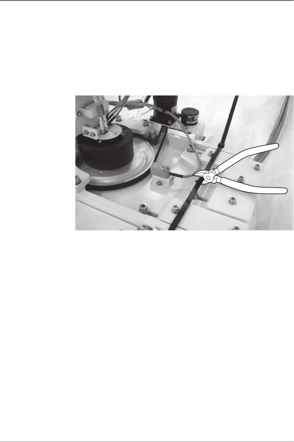
Secure the RF Cables
Using tie wraps supplied with radome, secure the RF cables connected to the
power switch box. Reinstall the hatch to the radome after the cable connection is
established.
NOTE: Tightening torque
Radome RF Cable Plate
Cable Tie Mount M4
Connector Type Tightening Torque
F Type 1.0 N-m
SMA 0.6 N-m
N Type 1.5 N-m

INSTALLING THE ACU
Mounting the ACU
19” Rack Mount Type
Table Mount Type
ACU Dimensions
Selection of ACU Installation Site
Ship Gyro Connection
Connecting the System with a Ship’s Gyro
Connecting the System without a Ship’s Gyro
ACU Connector Guide
v130 – Marine Satellite Communication System
34
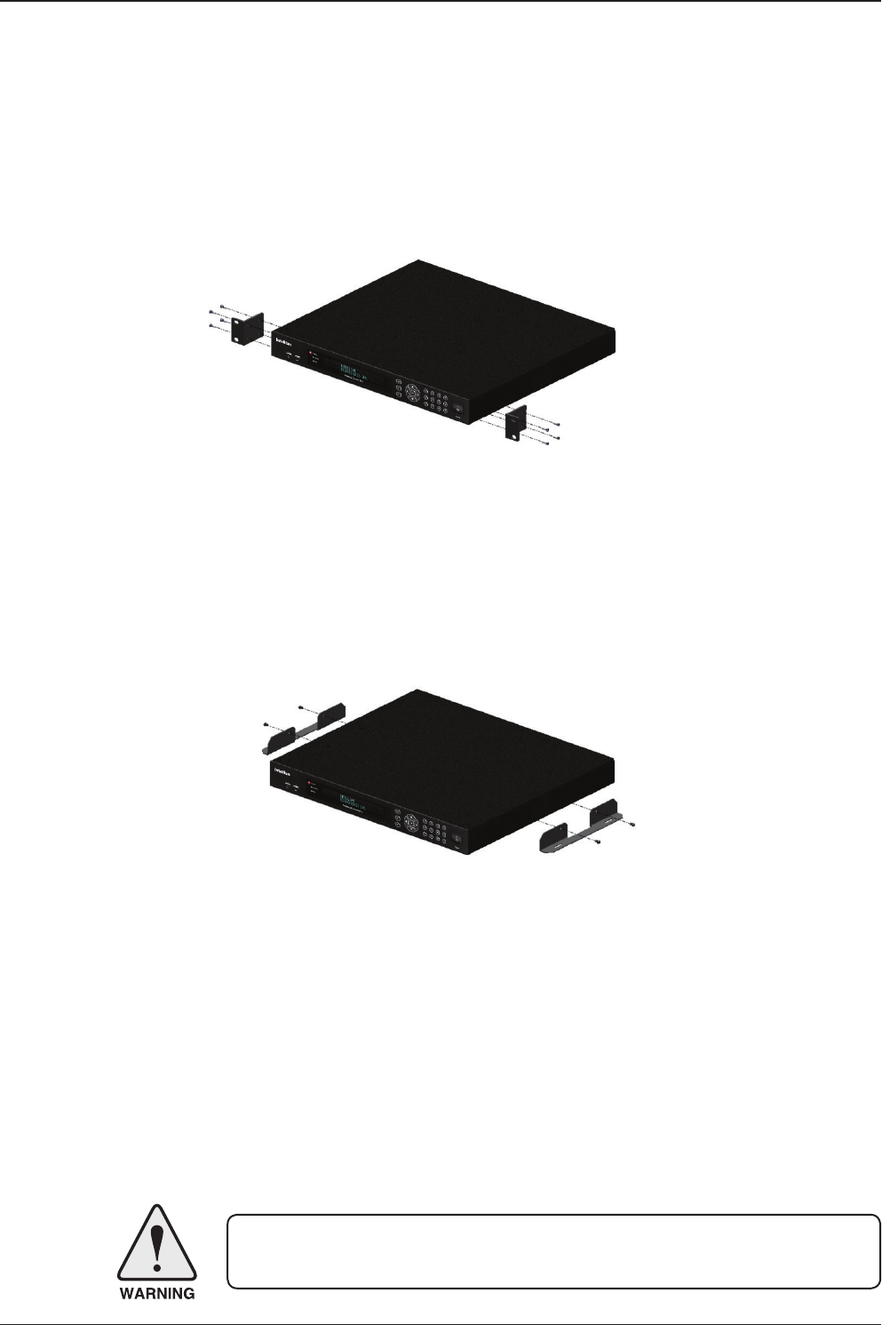
Mounting the ACU
Intellian supplies two types of mounting methods (a) 19” Rack Mount Type and (b)
Table Mount Type to mount your ACU.
19” Rack Mount Type
- The ACU should be installed using the two supplied rack mounting brackets which
allow for a side 19” rack mounting conguration.
- Using the self tapping screws supplied, attach the mounting brackets to the sides
of the ACU.
- Place the ACU in the location where it is going to be installed.
- Connect the cables to the rear of the ACU.
Table Mount Type
- The ACU should be installed using the two supplied table mounting brackets
which allow for a top or bottom mounting conguration.
- Using the self tapping screws supplied, attach the mounting brackets to the sides
of the ACU.
- Place the ACU in the location where it is going to be installed.
- Using a pencil to mark the 4 hole positions (2 each side), and use the appropriate
drill bit to mount the unit.
- Connect the cables to the rear of the ACU.
WARNING: Ensure that the cables connected to the ACU are long enough to prevent
damage when the ACU is pulled out from the rack.
19" Rack Mount Type
Table Mount Type
35
INSTALLING THE ACU
Selection of ACU Installation Site
The ACU should be installed below deck, in a location that is:
• Dry, cool, and ventilated.
• The front panel should be easy accessible to user.
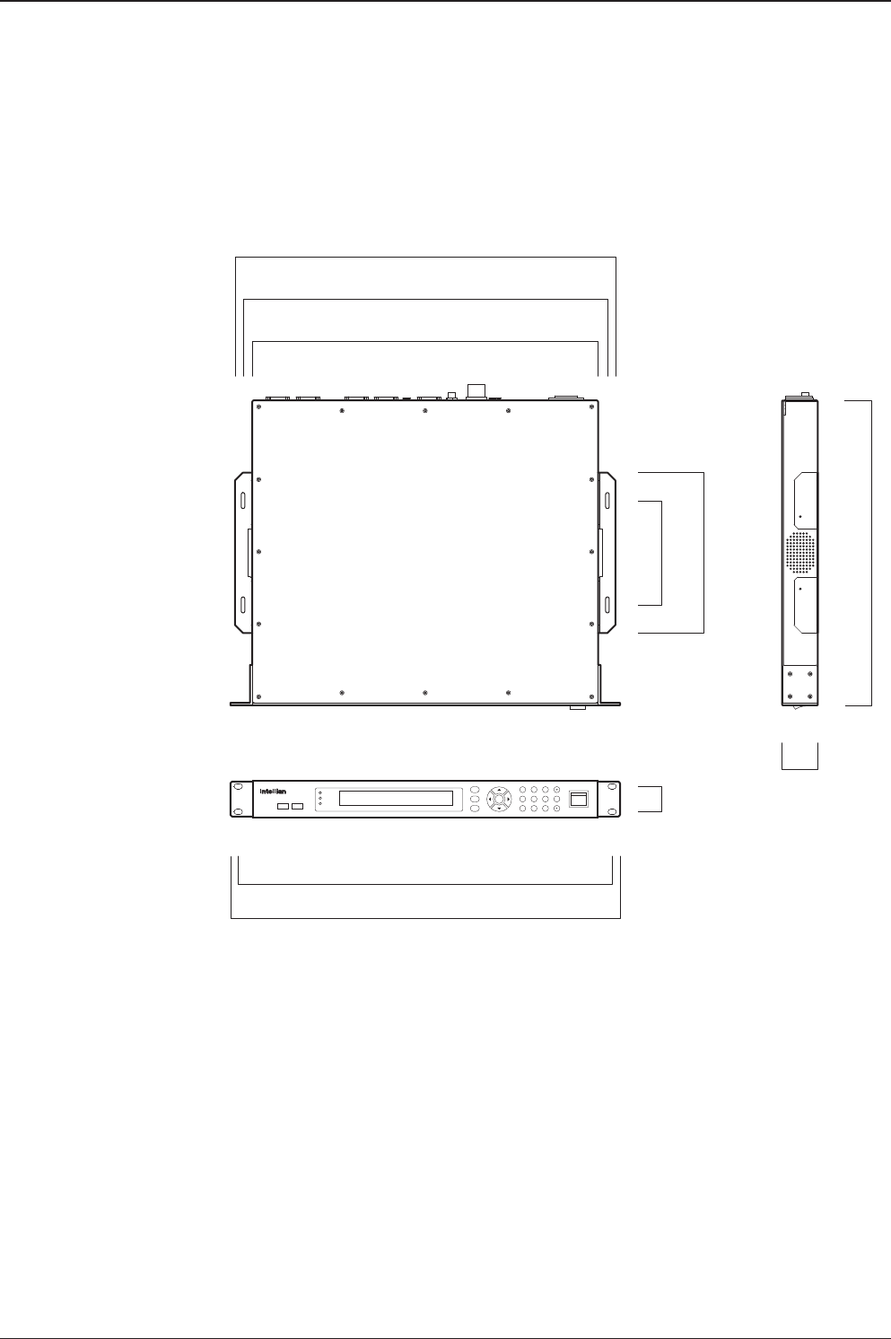
POWER
Antenna Control Unit
Power
M
R
123
4560
789
F
TRACKING
ERROR
DNPC
OK
3.2 cm (1.3")
46.5 cm (18.3")
48.5 cm (19.1")
13 cm (5.1")
20 cm (7.9")
43.1 cm (17")
45.4 cm (17.8")
47.4 cm (18.6")
4.4 cm (1.7")
38.1 cm (15")
ACU Dimensions
Dimension of ACU

v130 – Marine Satellite Communication System
36
Ship Gyro Connection
Connecting the System with a Ship’s Gyro
The ship’s gyrocompass provides true heading input to the antenna which easily
allows the antenna to target and acquire the desired satellite. Intellian always
recommend to connect a ship’s gyro to the antenna through the gyro interface on
the ACU. If the ship’s gyrocompass output is other than NMEA 0183 and Synchro
separate purchase of a gyro converter is required.
• NMEA 0183 Gyro Compass Interface Cable (Customer Supplied)
• Type: 2 conductors for NMEA 0183
• NMEA heading sentence: xx HDT (4800 Baud, 8, N,1)
If there is no HDT sentence then use HDM sentence instead.
WARNING: Determine the type of gyrocompass OUTPUT on the ship, assure that the
GYRO TYPE parameter is set correctly (refer to the operation section of this menu).
Heading in most cases will be 000.0 and you will have to enter the initial value of ships
current value whenever you turn on the ACU. The ship’s heading is not required to
input when your system is connected to NMEA or 1:1 synchro gyrocompass output.
Ship’s Gyro Connection
Strip the cable for 5 mm (0.2")
Do not solder the cable

37
INSTALLING THE ACU
Connecting the System without a Ship’s Gyro
For a vessel where the ship’s gyrocompass is not installed or is difcult to be
connected, the Intellian Gyro-Free satellite search function will be automatically
enabled to allow the antenna to lock onto the desired satellite without requiring an
external heading input.
The table below provides an example of the gyro-free satellite search algorithm.
The Search 1 or Search 3 satellite search pattern will be triggered according to the
existence of heading input and the setting of the heading device.
Search 1: The antenna will search for the target satellite by turning its azimuth
angle in CCW (Counter Clockwise) direction until the antenna receives
the lock signal from the modem or the DVB (Digital Video Broadcasting)
transponder of the target satellite is decoded by the antenna.
Search 3: The antenna will search for the target satellite by turning its azimuth angle
directly to the position calculated using the ship’s heading input and lock
onto the satellite.
Quick Setup Procedure
• Set the satellite with DVB transponder as the target satellite.
• Set “No Device” to the heading device.
• The antenna will search for the target satellite by turning its azimuth angle in CCW
direction and lock onto the satellite signal until the antenna receives a lock signal
from the modem or the DVB transponder of the target satellite is decoded.
• Set the heading device as NMEA/Synchro
• Enter “Manual search” menu and press “Function” key to save the current settings.
Intellian ACU will automatically calculate and save the Bow offset.
• Upload the real TARGET satellite pre-congured from the library.
Setting of Heading Device
Existence of Heading Data No Device NMEA/Synchro Ground Test
With Heading Data Search 1 Search 3 Search 3
Without Heading Data Search 1 Search 1 Search 3

v130 – Marine Satellite Communication System
38
ACU Connector Guide
• Console Port
NOTE: NMEA GPS IN/OUT Sentence: GPGLL (4800 Baud, 8, N, 1)
12345
6789
54321
9876
12345
6789
54321
9876
Pin Signal Pin Signal
1GND 6GPS OUT -
2GPS OUT + 7MODEM_SIGNAL_IN
3MODEM_LOCK 8MODEM_CTRL2
4MODEM_CTRL1 (TX MUTE) 9GPS IN -
5GPS IN +
ACU Console Port
D-Sub 9 pin Female
D-Sub 9 pin Male connector
Supplied Component
12345
6789
54321
9876
12345
6789
12345
6789
Pin Signal Pin Signal
1-6-
2-7-
3SYNCHRO_R2 8SYNCHRO_R1
4SYNCHRO_R3 9SYNCHRO_S2
5SYNCHRO_S1
Pin Signal Pin Signal
1-6-
2RXD 7-
3TXD 8-
4-9-
5GND
Pin Signal Pin Signal
1-6-
2RXD + 7RXD -
3TXD + 8TXD -
4-9-
5GND
ACU Synchro Port
D-Sub 9 pin Female
D-Sub 9 pin RS232
Connector
D-Sub 9 pin Male connector
Supplied Component
D-Sub 9 pin Male connector
Supplied Component
• Synchro Connector
• RS232/422 Connector (Modem & BUC Interface)

OPERATING THE ACU
Introduction
Normal Mode
Setup Mode
Installation Settings
Antenna Settings
Manual Search
Setup Antenna LNB Polarization Angle
Search Parameters
Setup Antenna Parameters
Setup Block Zone
Antenna Diagnostic Test
Satellite Settings
Load Satellite
Edit Satellite Information
Add Satellite Information
Check NID
System Settings
Set LNB Local Oscillator Frequency
Set Location
Set Modem Port
System Backup & Restore
Display Versions

v130 – Marine Satellite Communication System
40
This section of the handbook describes how to setup your system after installing
the ACU. It includes the following functions:
Introduction
ACU Soft Keys
Soft key Function
MODE Enter SETUP mode
RETURN
In SETUP mode: return to previous menu/option or save the
adjusted settings.
In normal mode: return to the rst page of antenna current status.
FUNCTION Save the adjusted settings.
ARROW KEYS Select from the alternative options to increse or decrese the
selected character to the desired value.
OK Enter next step/menu
NUMBER KEYS Input the numbers
Soft Key Functions
PC Cable (USB) Status LED Return Function Number Keys Power
Mode Arrow Keys

41
OPERATING THE ACU
INTELLIAN TECHNOLOGIES INC.
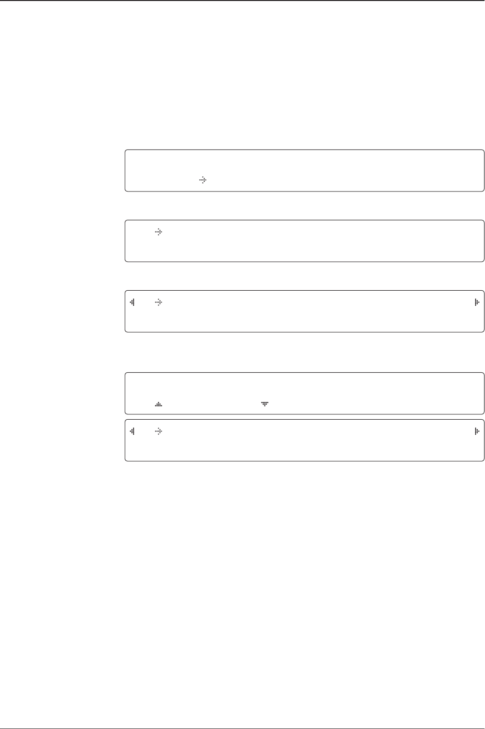
1. The data communication is being established between the antenna and the ACU.
INITIALIZE - ANTENNA INFO
INTELLIAN V110
2. The ACU receives antenna information.
INITIALIZE - EL POSITION
INTELLIAN V110
3. The elevation angle and cross level angle are initialized.
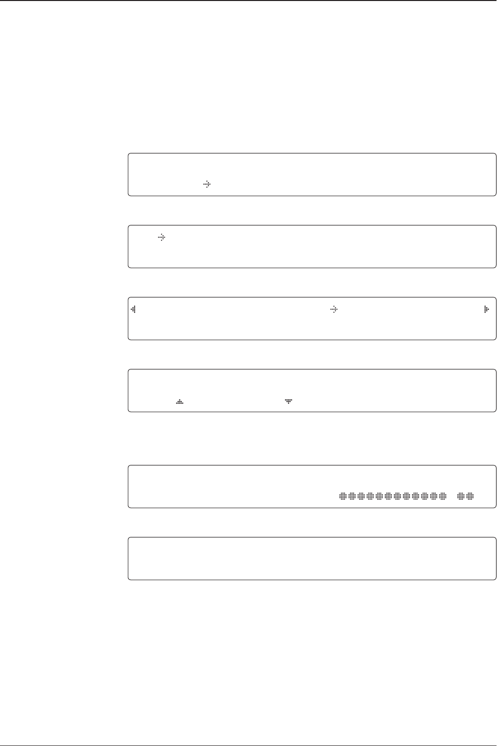
INITIALIZE - AZIMUTH POSITION
INTELLIAN V110
4. The azimuth angle is initialized.
INITIALIZE - SAT POSITION
INTELLIAN V110
5. The antenna returns to the target satellite position.
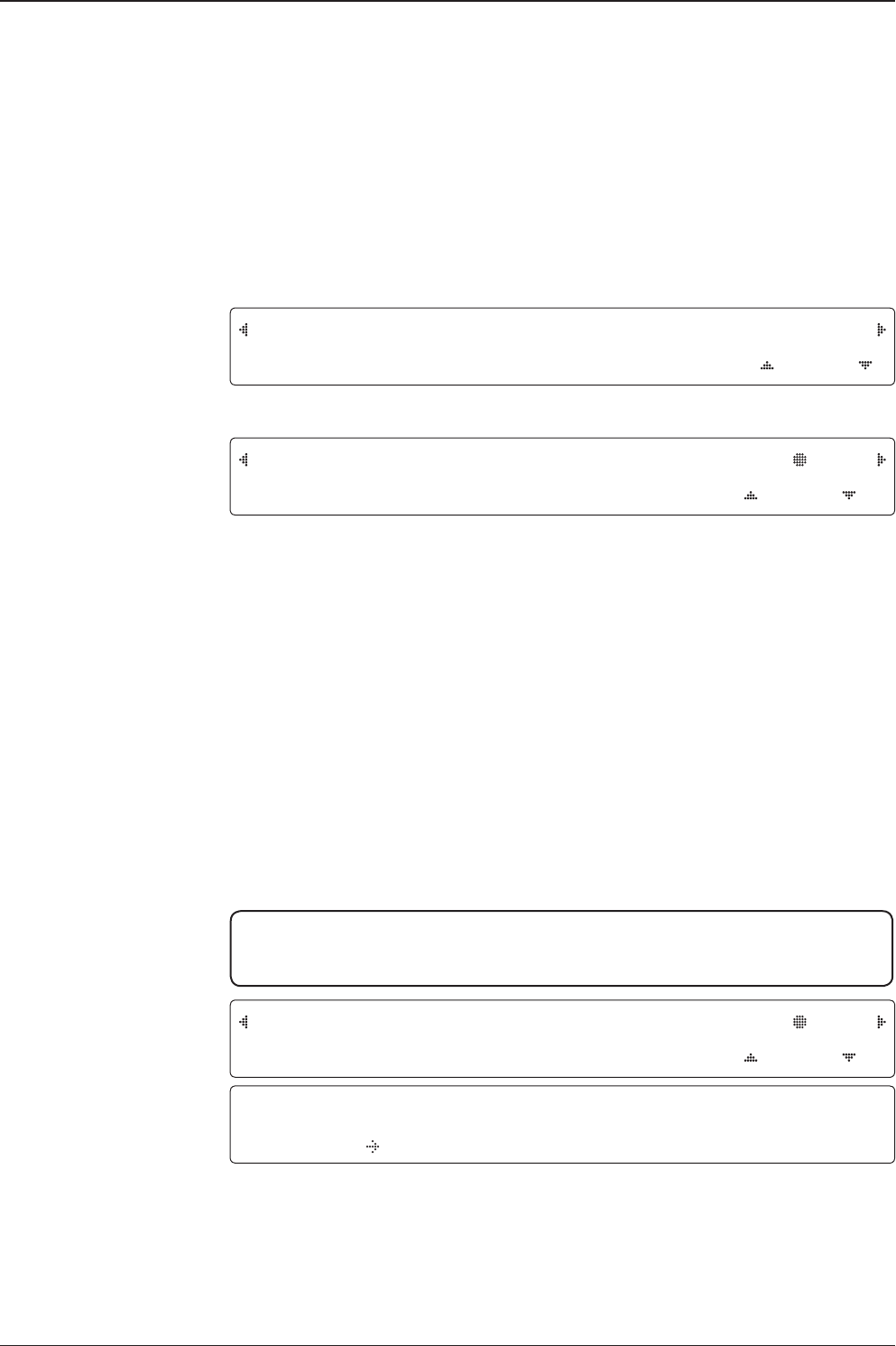
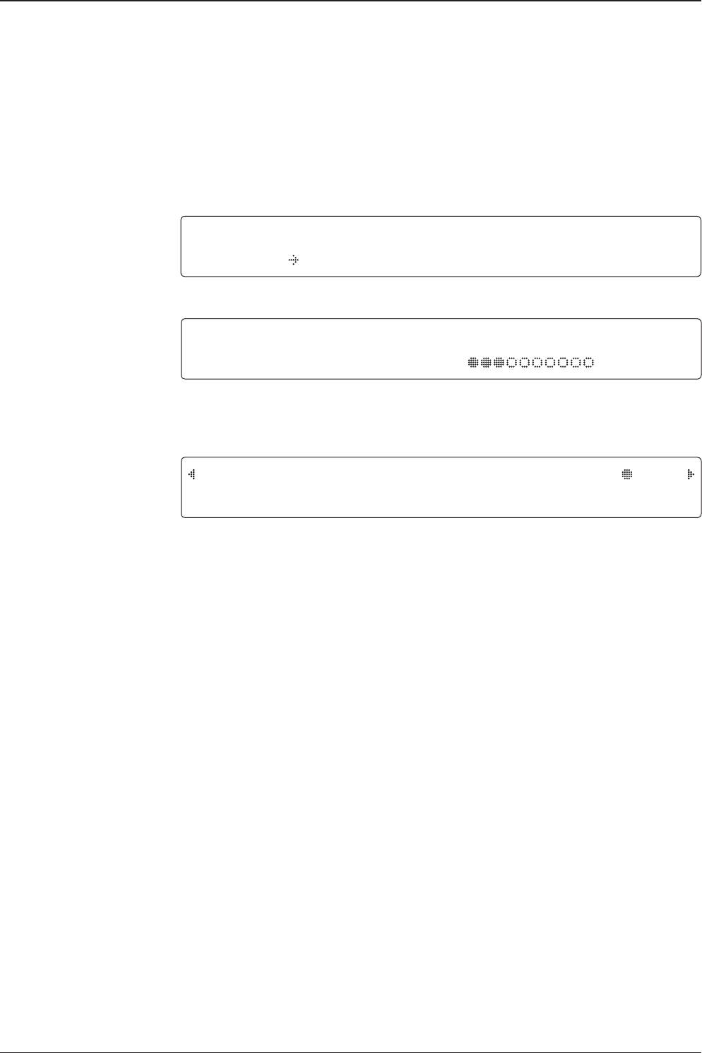
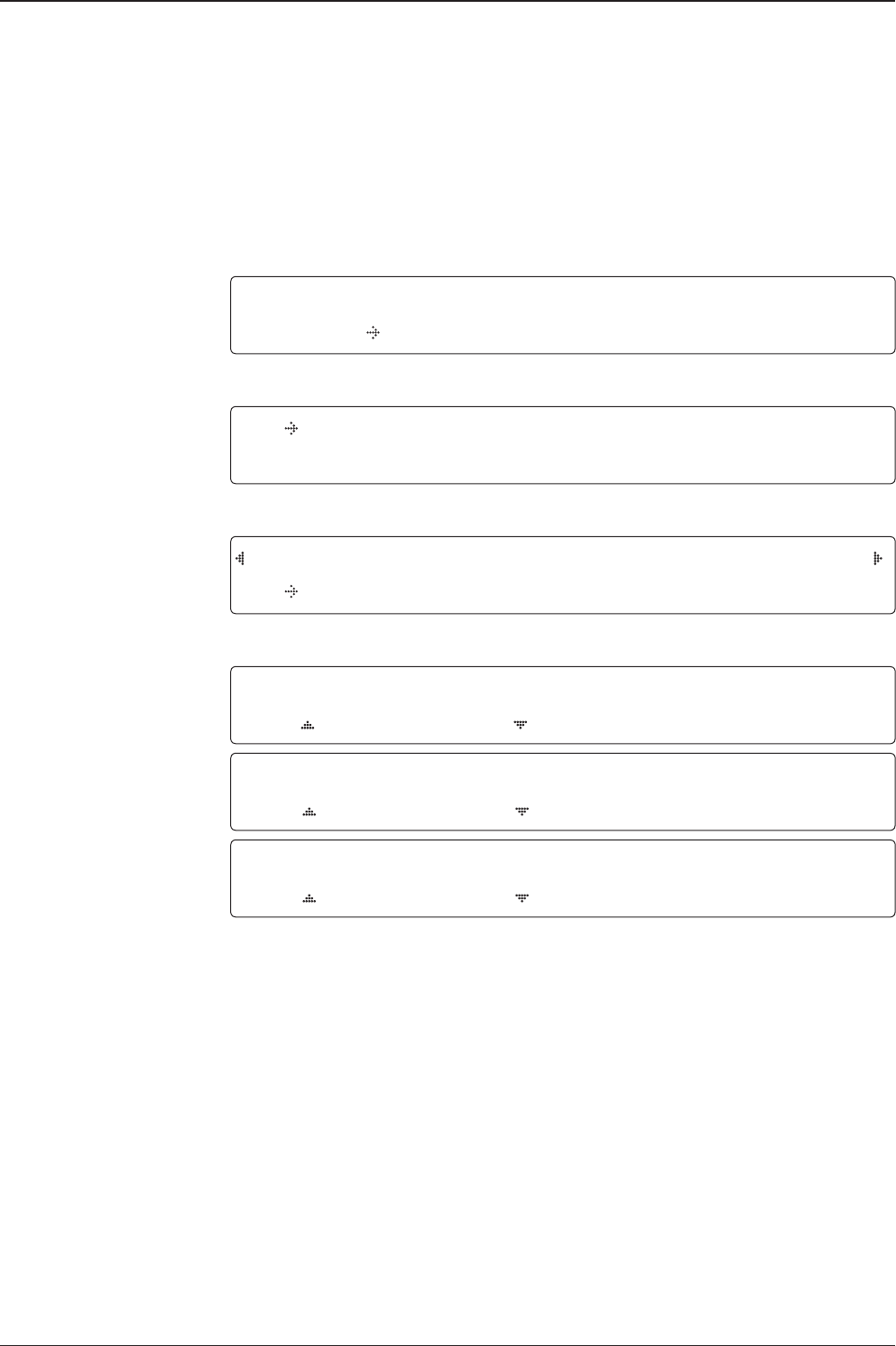
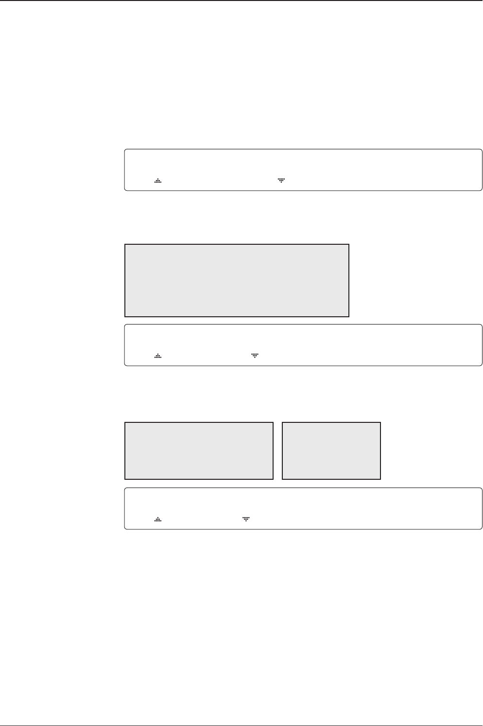
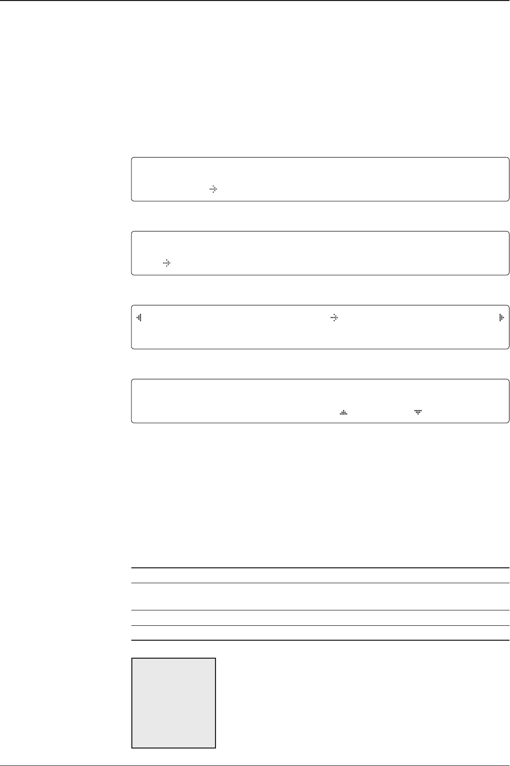
SEARCH1 138.0E TELST_18 SIG:301 VL
AZ:292.7( 202.7) EL: 48.3 SK: -72.0
6. The antenna is searching for the target satellite.
TRACKING 138.0E TELST_18 SIG:501 VL
AZ:292.7( 202.7) EL: 48.3 SK: -72.0 Fn
7. The antenna has locked onto the satellite.
Startup
With the system installed and power applied, the ACU screen will show the following
sequence.
Normal Mode
Start up
Initialize antenna info
Initialize elevation &
cross level angle
Initialize azimuth angle
Initialize target satellite
position
Search status
Tracking status
v130 – Marine Satellite Communication System
42
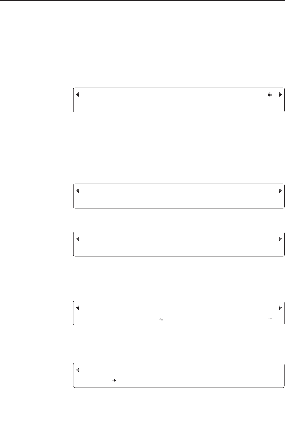
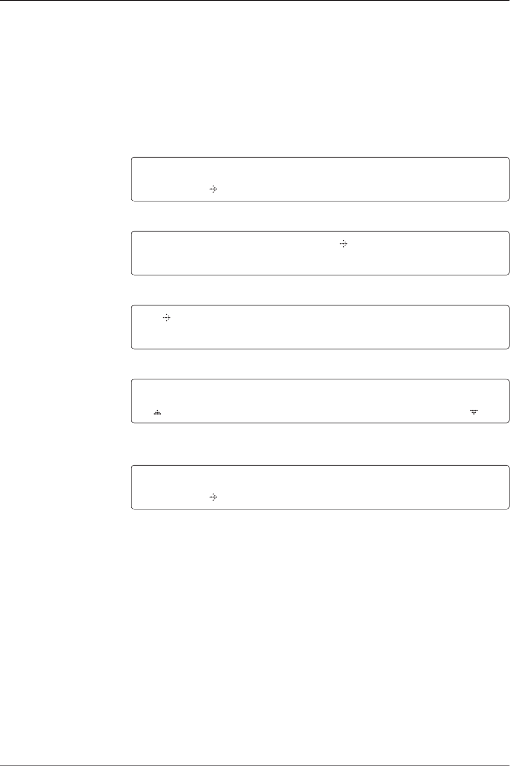
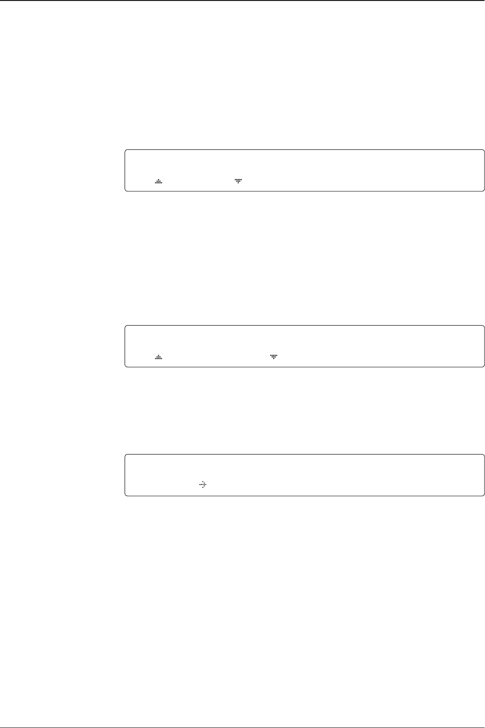
SEARCH1 138.0E TELST_18 SIG:301 VL
AZ:292.7( 202.7) EL: 48.3 SK: -72.0
1. The antenna is searching for the target satellite.
TRACKING 138.0E TELST_18 SIG:301 VL
AZ:292.7( 202.7) EL: 48.3 SK: -72.0 Fn
2. The antenna has locked onto the target satellite.
Current IF signal level (SIG/AGC) is displayed. SIG will be displayed when NBD (Narrow band
detection) mode for TRACKING SIGNAL is chosen to be used and AGC will be displayed
when DVB mode of TRACKING SIGNAL is chosen to be used.
The symbol “•” will be only displayed when the satellite signal is strong enough to locked
onto. [VL] indicates the LNB's local frequency corresponding to 13V is in use for the signal
reception.
VL: 13V + 0 kHz, HL: 18V + 0 kHz, VH: 13V + 22 kHz, HH: 18V + 22 kHz
Press the UP or DOWN arrow key to increase or decrease the LNB skew angle.
True azimuth [292.7] position of the antenna is the sum of ships heading 090.0 [HDG] and
antenna relative [202.7].
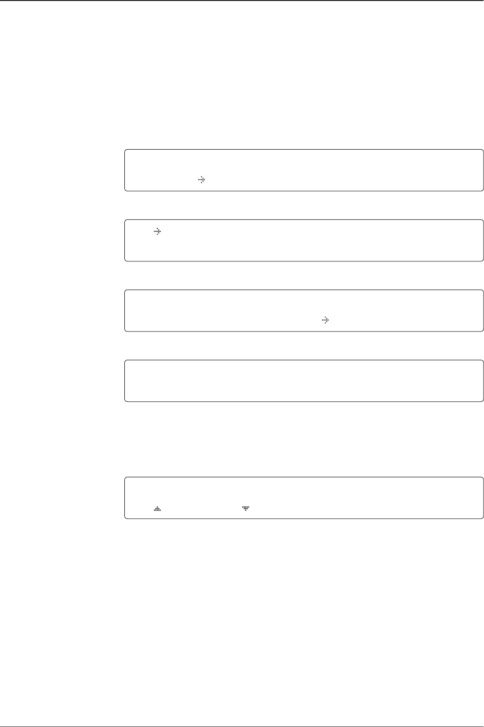
SAVE CURRENT SAT INFO ?
YES NO
3. Press FUNCTION key to save current satellite information or abort and return to the main
display. "Fn" will be displayed only if the antenna is in tracking mode.
NOTE: However, if the "GYRO TYPE" is set to "NONE" or "NMEA" but without
receiving a proper input signal, "---.-" will be displayed at "True Azimuth"
Monitoring Antenna Current Status
When the ACU power is on, it displays the status of the antenna. The current status
of the antenna is displayed as shown below.
Current search status
Current tracking status
Save current satellite info
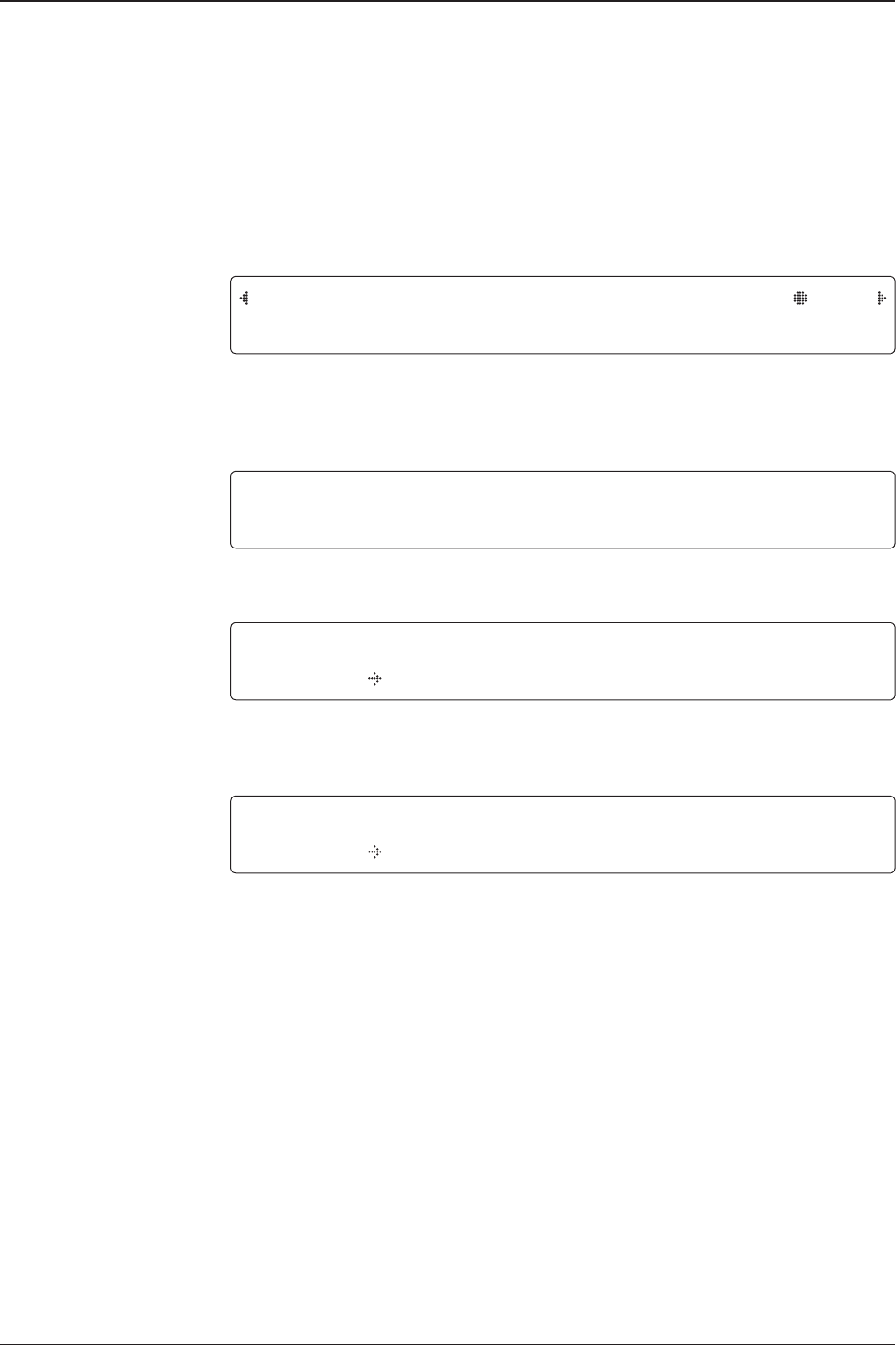
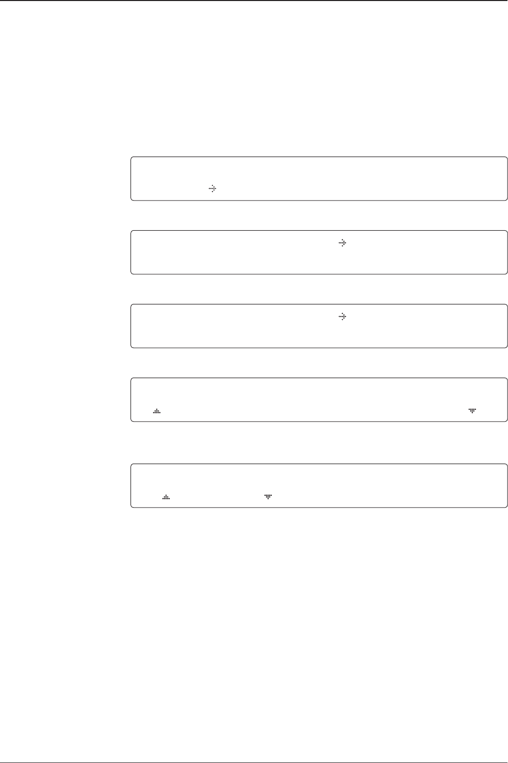
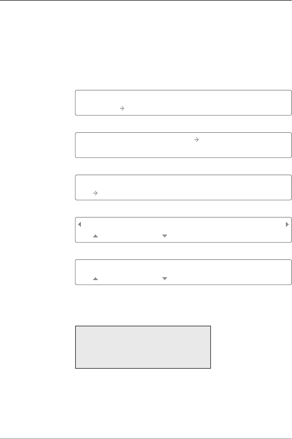
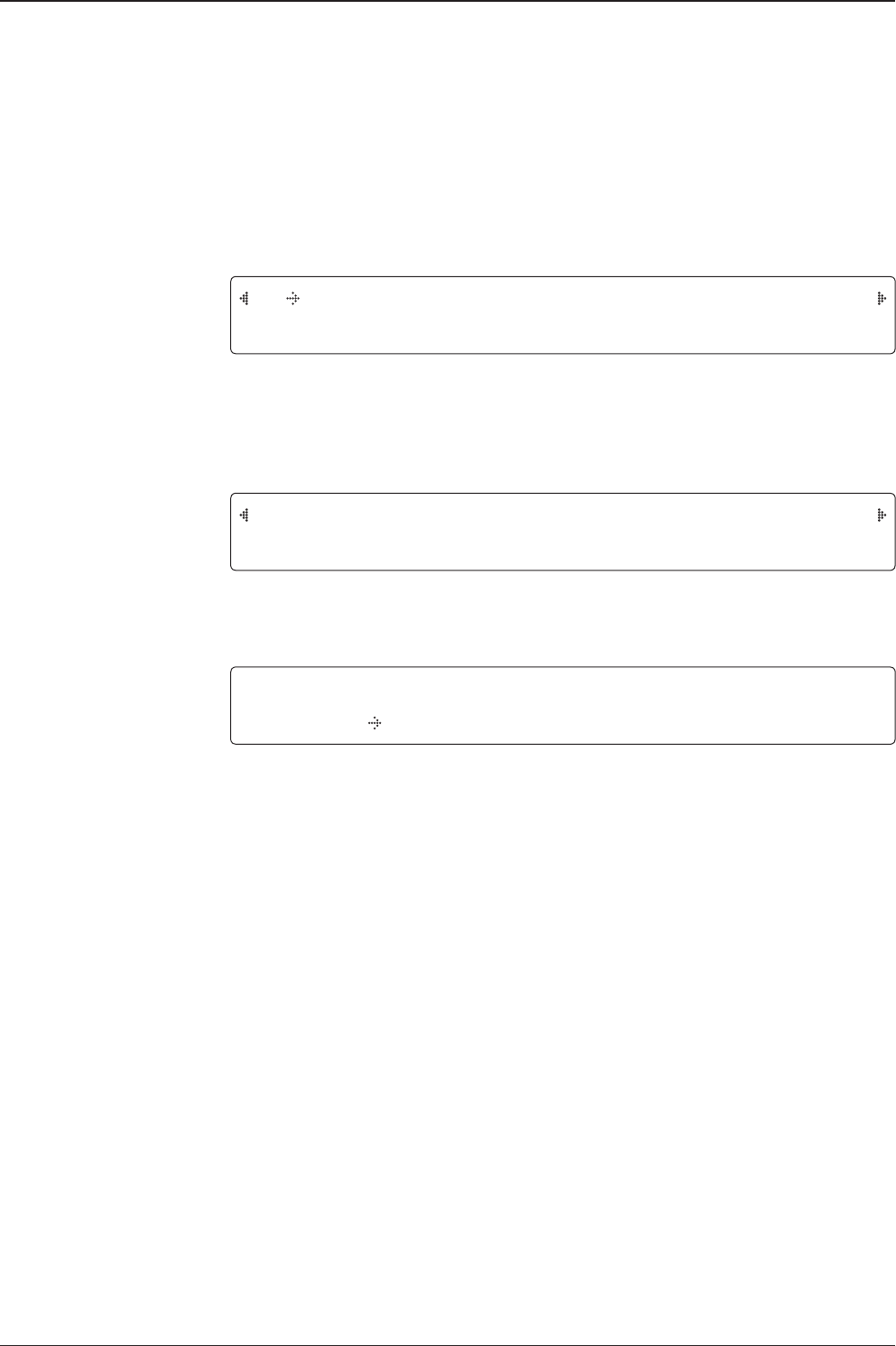
TRACKING 138.0E TELST_18 SIG:301 VL
AZ:---.-( 202.7) EL: 48.3 SK: -72.0 Fn
43
OPERATING THE ACU
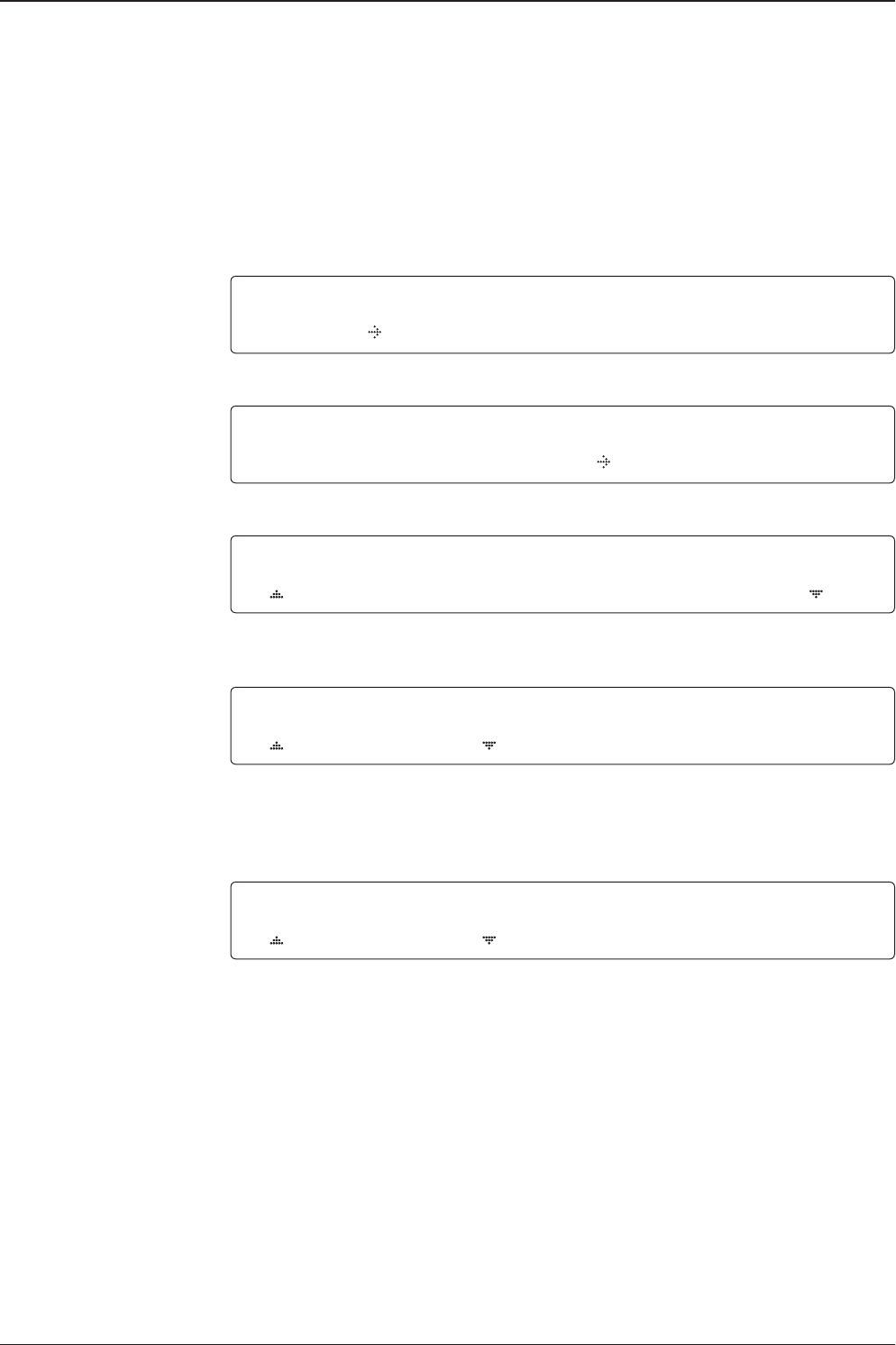
NBD F:1247000 BW:1000 SIG:301
004.53E 52.22N HDG:090.0 L:10000 Fn
5. NBD, GPS and ship’s heading information are shown.
- NBD (Narrow Band Detection) IF tracking frequency: 1247000 kHz
- Detected Band Width: 1000 kHz
- SIG (Signal Level ): 301 (When NBD mode for tracking signal is chosen)
- W (West)/E (East) Longitude: 4.53º E
- N (North)/S (South) Latitude: 52.22º N
- HDG (Ship’s Heading): 90º
- LNB local oscillator (LO) frequency: 10000 MHz
[PWR] ANT: 26.4V LNB: 13V + 0KHZ
ACU: 27.1V [POL] TX:V RX:H
6. Press RIGHT arrow key to display the current operation voltage for antenna, ACU and
LNB. POL indicates the TX polarity (VERTICAL) and RX polarity (HORIZONTAL).
V1-110-23H ANT. SERIAL 1.00
VP-T201 ACU SERIAL 1.00(1.00)
7. Press RIGHT arrow key to display the below information.
- Antenna part number, antenna serial number and PCU rmware version.
- ACU part number, ACU serial number, ACU rmware version and Library version.
Press RETURN Key to return to the rst page of the antenna current status.
8. Press RIGHT arrow key to display the real-time diagnostic result.
The real-time diagnostic code will be displayed automatically if there is any error found
during the system operation. However, this page will not be displayed if there is no error
message.
9. Press FUNCTION key to erase diagnostic error message.
Tracking & Heading
information
Power status
Antenna & ACU
versions
[DIAGNOSIS] SENSOR BOX
CODE109 RESULTS : FAILED FN
ERASE DIAGNOSIS ERROR LOG ?
YES NO
Real-time
diagnostic
result
Erase
Error message
v130 – Marine Satellite Communication System
44
Setup Mode
Enter the SETUP mode simply follow the instructions below.
Searching / Tracking mode
Enter password
Setup mode
Exit setup mode
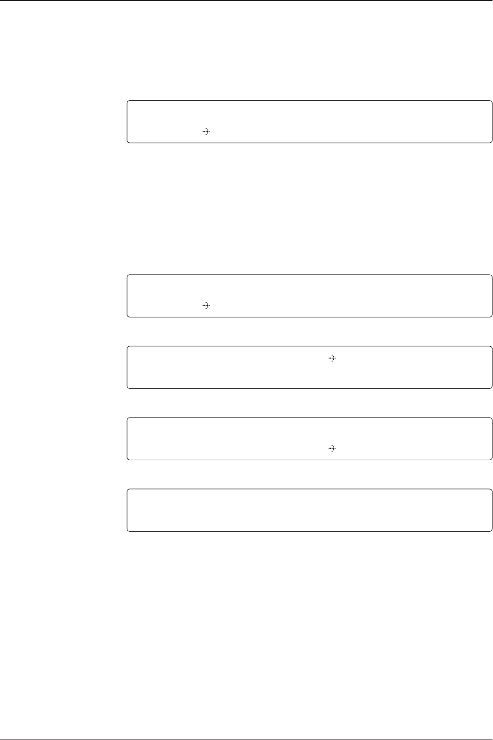
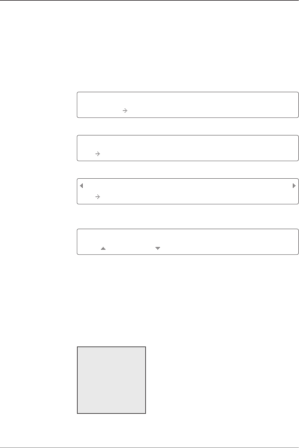
TRACKING 138.0E TELST_18 SIG:301 VL
* AZ:292.7( 202.7) EL: 48.3 SK: -72.0 Fn
1. While the antenna is in SEARCHING/TRACKING mode, press MODE key to enter SETUP
mode. * indicates the key pad lock function is on (Refer to KEY LOCK menu to setup the key
pad lock function). When key pad lock function is activated press MODE key or when “Fn”
menu is activated press FUNCTION key the ENTER PASSWORD menu will be displayed.
ENTER PASSWORD
- - - -
2. If the key pad lock function is on, enter the password before accessing to the SETUP
mode. If the key pad lock function is off, access to the SETUP mode directly as Step 3.
SETUP MODE ?
YES NO
3. Press LEFT arrow key to move cursor to YES and press OK key to enter SETUP mode or
press RIGHT arrow key to move cursor to NO and press OK key to abort and return to the
main display.
EXIT SETUP MODE ?
YES NO
4. While the antenna is in SETUP mode, press FUNCTION key as shortcut key to exit SETUP
mode.
45
OPERATING THE ACU
Installation Settings
During the rst time installation, it is required to setup the installation settings.
Installation
menu
Latitude & Longitude
Gyro type
Select satellite
Setup mode SETUP MODE ?
YES NO
1. Press LEFT arrow key to move cursor to YES and press OK key to enter SETUP mode
+ANTENNA +SATELLITE
+SYSTEM +INSTALLATION
2. Press arrow keys to move cursor to INSTALLATION menu and press OK key to enter it.
SELECT SATELLITE
[1] TELST_18 138.00E
3. Press UP and DOWN arrow keys to select the satellite that you wish to track and press OK
key to load the selected satellite.
LATITUDE LONGITUDE
37.00N 126.53E
4. Set the current LATITUDE and LONGITUDE
Press LEFT and RIGHT arrow keys until the desired character is underscored (selected).
Press UP and DOWN arrow keys to increase or decrease the value. Or press NUMBER keys
to set the desired value directly. Press OK key to set the parameter.
GYRO TYPE BOW ADJUST
NMEA 000
5. Set the ship’s GYRO TYPE* & BOW ADJUST
A search pattern 1 or 3 will be initiated according to which Gyro Type is selected and the
existence of the gyro input. Ensure that the supported Gyro Type is set correctly. For v130, if
the ship's gyrocompass output is Step-by-Step (SBS) or Synchro, a separate purchase of a
gyro converter is required. If the ship’s gyrocompass output is other than NMEA & Synchro,
a separate purchase of a gyro converter is required.
A search pattern 1 will be initiated automatically if the gyro input does not exist and the gyro
type is selected other than GROUND TEST.
The BOW ADJUST is to offset the angle difference between the antenna’s bow and the ship’s
bow (Range: 0 – 360°).
NOTE: The bow offset will not be saved automatically if Search 1 pattern is initiated. In this case, the
antenna will need to retarget the desired satellite using Search 1 every time if the antenna restarts.
v130 – Marine Satellite Communication System
46
6. Set MODEM PORT* and MODEM PROTOCOL*
MODEM PORT is to select a proper data communication port on the ACU to interface with
the satellite modem. MODEM PROTOCOL is to select a proper communication protocol on
the ACU to interface with the satellite modem.
13V + 0KHZ 18V+0KHZ
10000MHZ 11300MHZ
13V +22KHZ 18V+22KHZ
10000MHZ 09750MHZ
7. Set the LNB local oscillator frequency for each voltage power. (13V +0 kHz, 18V +0 kHz,
13V +22 kHz, 18V +22 kHz)
Press LEFT and RIGHT arrow keys until the desired character is underscored (selected).
Press UP and DOWN arrow keys to increase or decrease the value. Or press NUMBER keys
to set the desired value directly.
MODEM PORT*
RS232
RS422
ETHERNET
Modem port & Modem
protocol
LNB local frequency
GYRO TYPE*
NO DEVICE
NMEA / SYNCHRO
GROUND TEST
Gyro search mode
MODEM PROTOCOL*
I/O CONSOLE
OPEN AMIP
SERIAL GPS
ROSS
Setting of Heading Device
Existence of Heading Data No
Device
NMEA/
Synchro
Ground Test
With Heading Data Search 1 Search 3 Search 3
Without Heading Data Search 1 Search 1 Search 3
MODEM PORT MODEM PROTOCOL
RS232 SERIAL GPS
47
OPERATING THE ACU
TRACKING 138.0E TELST_18 SIG:301 VL
AZ:292.7( 202.7) EL: 48.3 SK: -72.0 Fn
10. Antenna has locked onto the target satellite.
Tracking status
LOADING ...
DO NOT TURN OFF !
9. Setting is being loaded to the system.
The ACU will restart the system automatically after uploading the setting.
DO NOT TURN OFF ACU POWER while the data is being uploaded.
Loading settings
LOAD ?
YES NO
8. Press RETURN key to load the current setting or abort and return to the main display.
Load
v130 – Marine Satellite Communication System
48
Antenna Settings
Manual Search
Search the desired satellite manually.
Antenna movement
Setup mode
Save
Manual search menu
Antenna menu
SETUP MODE ?
YES NO
1. Press LEFT arrow key to move cursor to YES and press OK key to enter SETUP mode.
+ANTENNA +SATELLITE
+SYSTEM +INSTALLATION
2. Press OK key to enter ANTENNA menu.
+MANUAL SEARCH +SET POL ANGLE
+SEARCH PARAM +SET PARAMETERS
3. Press OK key to enter MANUAL SEARCH menu.
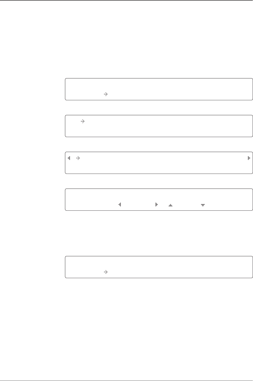
STEP SIZE AZIMUTH ELEVATION AGC
# 00.2 # 231.7 48.3 301 Fn
4. Current IF tracking signal level (AGC)/(SIG) is displayed to assist you in manually peaking
AZIMUTH (0°-360°) and ELEVATION (0°-90°) angle for best signal level.
Press NUMBER key to change the STEP SIZE (Range: 0.1~99.9). Press LEFT and RIGHT
arrow keys to increase or decrease the azimuth angles. Press UP and DOWN arrow keys to
increase or decrease the elevation angles.
Press FUNCTION key to save current settings or abort and return to the main display.
SAVE CURRENT SAT INFO?
YES NO
5. If the current settings are able to locate the satellite, press FUNCTION key to save “current
satellite information”. This will help to reduce the satellite acquisition time after restarting
the system. Press LEFT arrow key to move cursor to YES and press the OK key to save the
settings.
NOTE: If the gyro type is not NMEA or the gyro is not connected to the ACU, the information cannot be
saved.
49
OPERATING THE ACU
Setup Antenna LNB pol Angle
LNB pol angle type
Setup mode
Set pol angle menu
Antenna menu
LNB pol angle Signal
SETUP MODE ?
YES NO
1. Press LEFT arrow key to move cursor to YES and press OK key to enter SETUP mode.
+ANTENNA +SATELLITE
+SYSTEM +INSTALLATION
2. Press OK key to enter ANTENNA menu.
+MANUAL SEARCH +SET POL ANGLE
+SEARCH PARAM +SET PARAMETERS
3. Press RIGHT arrow key to move cursor to SET POL ANGLE menu and press OK key to
enter it.
SELECT POL ANGLE MENU
CALIBRATION
4. Press UP and DOWN arrow keys to select the LNB pol angle menu and press OK key to
run the selected operation 'CALIBRATION' or 'MANUAL ADJUST'. Select MANUAL ADJUST
to control LNB pol angle manually. If the control board, LNB pol potentiometer or belt is
replaced, select CALIBRATION to calibrate LNB pol angle.
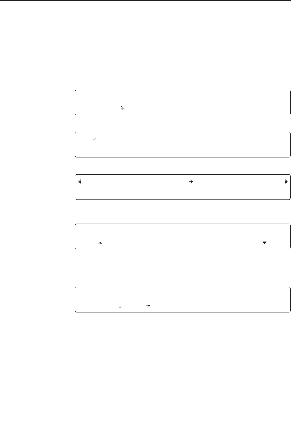
LNB POL ANGLE SIGNAL: 180
20
5. Press UP and DOWN arrow keys to increase or decrease the LNB pol angle manually and
the correspondent SIGNAL level will be displayed next to it. Press RETURN key to return to
the main display.
NOTE: LNB POL ANGLE menu will be displayed only if MANUAL ADJUST is selected.
v130 – Marine Satellite Communication System
50
Search 3 range
Search 1 range
Search Parameters
Setup mode
Manual search menu
Antenna menu
Search param
SETUP MODE ?
YES NO
1. Press LEFT arrow key to move cursor to YES and press OK key to enter SETUP mode.
+ANTENNA +SATELLITE
+SYSTEM +INSTALLATION
2. Press OK key to enter ANTENNA menu.
+MANUAL SEARCH +SET POL ANGLE
+SEARCH PARAM +SET PARAMETERS
3. Press arrow keys to move cursor to SEARCH PARAM menu and press OK key to enter it.
SEARCH WAIT TIME INCREMENT STEP
030 0.50
SEARCH1 AZ SEARCH1 EL
400 06
SEARCH3 AZ SEARCH3 EL
003 04
4. Set SEARCH 1 and 3 AZ (Azimuth) range and EL (Elevation) range. SEARCH 2 is reserved
for future use.
A search pattern 1 or 3 will be initiated according to which GYRO TYPE is selected
and the existence of the gyro input.
Search 1: A search pattern 1 will automatically be initiated when the ship’s heading
input does not exist/is failed. The antenna will go to the relative azimuth position 0º
at the calculated elevation and search in the azimuth CCW direction and search up
+0.5º & down -0.5º with a total 6º(±3º) in elevation. The search cycle will repeat until
the antenna receives the lock signal from the modem or the DVB transponder of the
target satellite is decoded by the antenna. If the desired signal is found and above
the predened detect level, the ACU will enter to Search 3. However, the antenna
will not initiate Search 3 pattern but go into TRACKING mode immediately if the
desired signal is above the predened tracking threshold level. If the detected signal
is below the predened tracking threshold level, the search 1 will repeat and start 3º
away from the current position.

51
OPERATING THE ACU
-3°
-2°
-1°
0°
1°
2°
3°
1 5 10 15 20 3025
Search 1 (Gyro Free) Search Pattern
Search 3 pattern
Elevation
(EL) Range
0.5˚
Azimuth (AZ) Range
Search 3: A search pattern 3 will automatically be initiated when AGC/SIG falls
below the current tracking level threshold value. If the desired signal is found and
above the predened tracking level, the ACU will terminate Search 3 and go into
TRACKING mode. A search pattern will automatically be initiated when AGC/SIG
falls below the current threshold setting (indicates that satellite signal has been
lost). Search is conducted in a two-axis pattern consisting of alternate movements
in azimuth (AZ) and elevation (EL) as forming expanding square indicated as below
diagram.
Target Satellite EL Position
Revolution (AZ direction)
Target EL Angle
Turn 1
Target EL Angle + 0.5°
Turn 2
Target EL Angle - 0.5°
Turn 3
Search 1 antenna motion
v130 – Marine Satellite Communication System
52
Password
Antenna menu
Set parameters menu
Setup mode
Set detect & tracking DVB
Setup Antenna Parameters
These parameters should only be changed by an authorized Intellian service
technician. Improper setting of these parameters will cause your system to perform
improperly.
SETUP MODE ?
YES NO
1. Press LEFT arrow key to move cursor to YES and press OK key to enter SETUP mode.
+ANTENNA +SATELLITE
+SYSTEM +INSTALLATION
2. Press OK key to enter ANTENNA menu.
+MANUAL SEARCH +SET POL ANGLE
+SEARCH PARAM +SET PARAMETERS
3. Press arrow keys to move cursor to SET PARAMETERS menu and press OK key to enter it.
ENTER PASSWORD
- - - -
4. Press 4 digit password to enter SET PARAMETERS menu (1590).
Setup parameters is only required after installation or repairs of your antenna system.
These parameters should only be changed by an authorized service technician.
Improper setting of these parameters will render your system inoperable.
DETECT DVB TRACKING DVB
040 020
5. Set DETECT DVB and TRACKING DVB when DVB mode of TRACKING SIGNAL is chosen
to be used (Range: 1-200).
DETECT DVB is to set the satellite signal detection level and TRACKING DVB is to set the
satellite signal tracking level.
Press LEFT and RIGHT arrow keys until the desired character is underscored (selected).
Press UP and DOWN arrow keys to increase and decrease the selected character.
Or press NUMBER keys to set the desired value directly. Press OK key to set the parameter.
Press RETURN key to select the parameter you wish to edit and press RETURN key again to
save or abort and return to the main display.
53
OPERATING THE ACU
Detect & tracking level
Set detect & tracking NBD
BOW & EL adjust
DETECT NBD TRACKING NBD
040 020
6. Set DETECT NBD and TRACKING NBD when NBD (Narrow Band Detection) mode of
TRACKING SIGNAL is chosen to be used (Range: 1-200).
DETECT NBD is to set the satellite signal detection level and TRACKING NBD is to set the
satellite signal tracking level.
Press LEFT and RIGHT arrow keys until the desired character is underscored (selected).
Press UP and DOWN arrow keys to increase and decrease the selected character.
Or press NUMBER keys to set the desired value directly. Press OK key to set the parameter.
Press RETURN key to select the parameter you wish to edit and press RETURN key again to
save or abort and return to the main display.
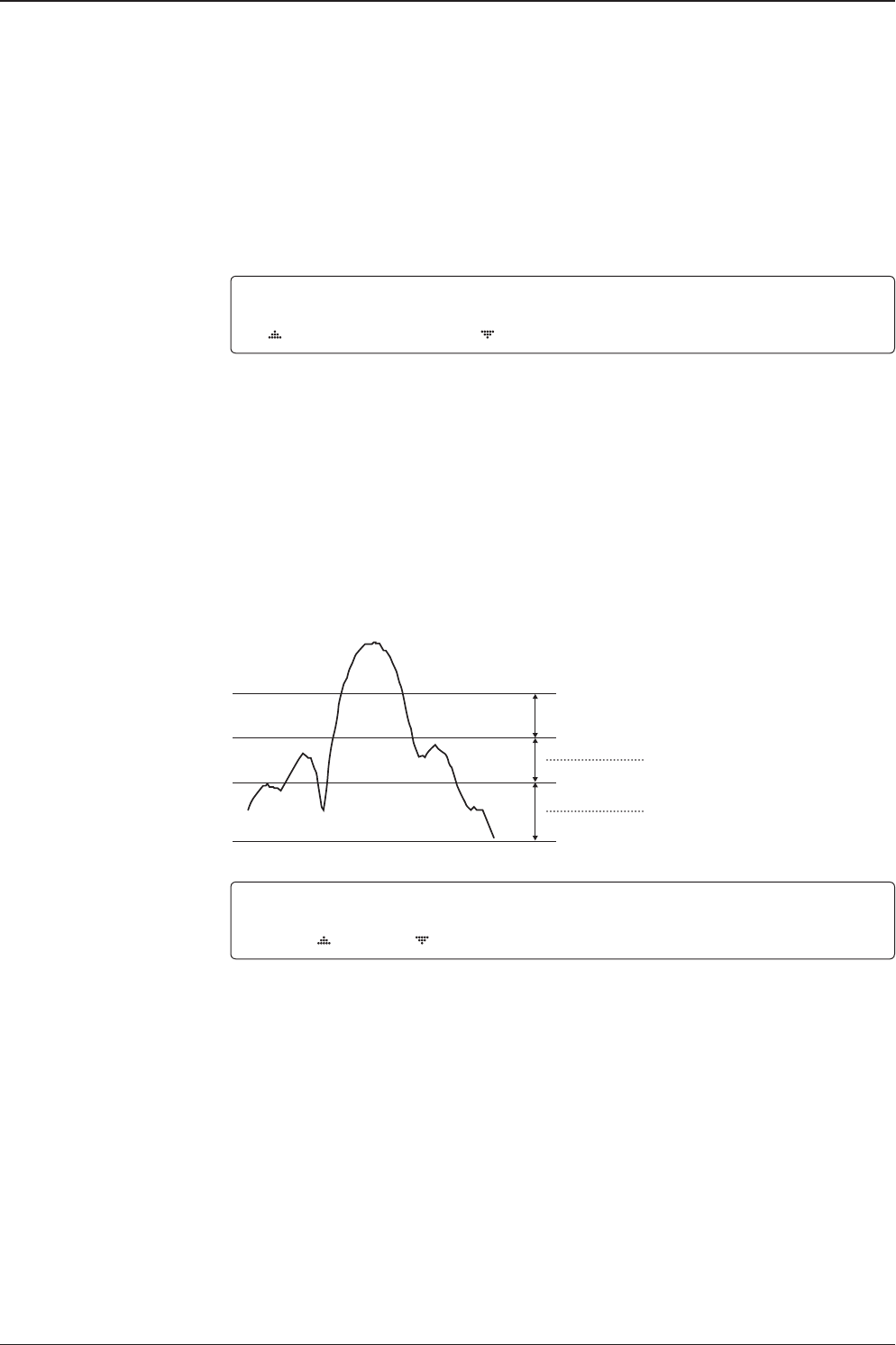
Noise Level
Detect Level
Tracking Level
TRACKING DVB/NDB
Peak Level
DETECT DVB/NDB
BOW ADJUST EL.ADJUST
000 +0.0
7. Set BOW ADJUST and EL. ADJUST
BOW ADJUST is to offset the angle difference between the antenna’s bow and the ship’s bow
(Range: 0 – 360°) and EL. ADJUST is to offset the angle difference between the mechanical
elevation angle and actual elevation angle (Range: ± 5°).
Press LEFT and RIGHT arrow keys until the desired character is underscored (selected).
Press UP and DOWN arrow keys to increase and decrease the selected character.
Or press NUMBER keys to set the desired value directly. Press OK key to set the parameter.
Press RETURN key to select the parameter you wish to edit and press the RETURN key again
to save or abort and return to the main display.
v130 – Marine Satellite Communication System
54
Level vial
Rate sensor bias
Tilt bias
Idle mode &
Reboot antenna IDLE MODE REBOOT ANTENNA
OFF NO
8. Set IDLE MODE and REBOOT ANTENNA
The antenna is balanced at factory. However, after disassembly for shipping, maintenance or
parts replacements, antenna balance adjustment may be required. The elevation and cross-
level motors have a brake mechanism integrated into them, therefore, antenna power and
IDLE MODE must be ON to release the motor brakes. Balancing is achieved by adding or
removing weight blocks at strategic locations to keep the antenna balanced.
IDLE MODE: Press UP and DOWN arrow keys to turn ON/ OFF IDLE MODE.
The motor brakes will be released while the IDLE MODE is ON. The antenna will restart
automatically if IDLE MODE is re-set from ON to OFF or RETURN key is pressed to exit
SETUP mode.
REBOOT ANTENNA: The antenna will restart automatically if REBOOT ANTENNA is ON.
+RATE SENSOR BIAS +TILT BIAS
9. Set RATE SENSOR BIAS
RATE SENSOR BIAS is to calibrate DC voltage output from the three rate sensors used to
sense antenna motion in azimuth, elevation and cross-level axes. The DC voltage output
from each of the rate sensors may be vary by an amount which is directly proportional to the
direction and rate of motion induced on it.
NOTE: The motion of the ship must be stable when the sensor box is replaced.
STEP SIZE ELEVATION CROSS LEVEL
# 0.2 # 00.0 01.0
10. Set TILT BIAS
TILT BIAS is to adjust the two solid-state tilt sensors used to provide absolute cross-level tilt
of the antenna and elevation feedback to eliminate long-term pointing drift (error). The TILT
BIAS is required to set when the system is newly installed, antenna control board or sensor
box is replaced. Check and see if the bubble is located at the center of the level vial. If not,
press OK key to enter TILT BIAS menu to adjust.
55
OPERATING THE ACU
Setup Block Zone
Up to 5 block or radiation hazard zones can be programmed with relative azimuth
and elevation sectors.
Block zone menu
Block zone range
Block zone 1
Antenna menu
Setup mode SETUP MODE ?
YES NO
1. Press LEFT arrow key to move cursor to YES and press OK key to enter SETUP mode.
+ANTENNA +SATELLITE
+SYSTEM +INSTALLATION
2. Press OK key to enter ANTENNA menu
+BLOCK ZONE +DIAGNOSIS
3. Press RIGHT arrow key to move cursor to BLOCK ZONE menu and press OK key to enter
it. Up to 5 block zones is allowed to be programmed.
ZONE 1 BLOCK
ON
AZ.1 START AZ.1 END EL.1 LIMIT
000 000 90
4. Set ZONE 1 BLOCK
Press UP and DOWN arrow keys to select “ON” to setup the block zone for ZONE 1.
Press OK key to use ZONE 1 BLOCK and set zone 1 block range.
Press RETURN key to select the parameter you wish to edit and press the RETURN key again
to save or abort and return to the main display.
Set the AZ.1 START, AZ.1 END and EL.1 LIMIT while ZONE 1 BLOCK is ON.
This is the clockwise of the two points. AZ.1 START is where the relative azimuth starts
and AZ.1 END is where the relative azimuth ends (Range: 0- 360°). EL.1 Limit is where the
elevation starts (Range 0- 90°).
Press LEFT and RIGHT arrow keys until the desired character is underscored (selected).
Press UP and DOWN arrow keys to increase and decrease the selected character.
Or Press NUMBER keys to set the desired value directly. Press OK key to set the parameter.
Press RETURN key to select the parameter you wish to edit and press RETURN key again to
save or abort and return to the main display.

v130 – Marine Satellite Communication System
56
Block zone 2
Save
ZONE 2 BLOCK
OFF
5. ZONE 2 to ZONE 5 BLOCK setting is same as ZONE 1 BLOCK.
Press OK key to set ZONE 2 BLOCK and set next parameter.
SAVE ?
YES NO
6. Press LEFT arrow key to move cursor to YES and press OK key to save and execute the
current settings. Or press RIGHT arrow key to move cursor to NO and press OK key to abort
and return to the main display.
57
OPERATING THE ACU
Antenna Diagnostic Test
Refer to the diagnosis codes for the test results.
Single diagnostic
test result
Full diagnostic test
Full diagnostic
test result
Diagnosis menu
Antenna menu
Setup mode SETUP MODE ?
YES NO
1. Press LEFT arrow key to move cursor to YES and press OK key to enter SETUP mode.
+ANTENNA +SATELLITE
+SYSTEM +INSTALLATION
2. Press OK key to enter ANTENNA menu.
+BLOCK ZONE +DIAGNOSIS
3. Press arrow keys to move cursor to DIAGNOSIS menu and press OK key to enter it.
DIAGNOSIS COMMUNICATION
FULL TEST READY
4. Press UP and DOWN arrow keys to select a full diagnostic test or single diagnostic test
and press OK key to execute the selected diagnostic test.
Menus for DIAGNOSIS are FULL TEST and CODE 101 ~ CODE 116.
DIAGNOSIS FULL TESTING
FULL TEST - -
5. A full diagnostic is successfully completed.
DIAGNOSIS COMMUNICATION
CODE 101 RESULT : PASSED
6. A single diagnostic test is successfully completed.

v130 – Marine Satellite Communication System
58
Diagnosis Code:
CODE 101: The data communication between the antenna and the ACU is tested.
CODE 102: The azimuth motor is tested.
CODE 103: The elevation motor is tested.
CODE 104: The cross-level motor is tested.
CODE 105: The azimuth encoder is tested.
CODE 106: The cross-level encoder is tested.
CODE 107: The rate sensor is tested.
CODE 108: The tilt sensor is tested.
CODE 109: The sensor box motor is tested.
CODE 110: The LNB/NBD is tested.
CODE 111: The LNB pol motor is tested.
CODE 112: The sub-reector is tested. (Skip for v-Series communication products)
CODE 113: The antenna power is tested.
CODE 114: The ACU power is tested.
CODE 115: The receiver power is tested.
(Skip for v-Series communication products)
CODE 116: The home sensor is tested.
An example of test result: •2••••••••••-••-
•: test is passed
2: test is failed (CODE102)
–: test is skipped (TVRO products only)
?: test is in process
59
OPERATING THE ACU
Satellite Settings
Load Satellite
Load
Load sat menu
Load satellite
Satellite menu
Setup mode SETUP MODE ?
YES NO
1. Press LEFT arrow key to move cursor to YES and press OK key to enter SETUP mode.
+ANTENNA +SATELLITE
+SYSTEM +INSTALLATION
2. Press RIGHT arrow key to move cursor to SATELLITE and press OK key to enter it.
+LOAD SAT. +EDIT SAT.
+ADD SAT. +CHECK NID
3. Press OK key to enter LOAD SAT. menu.
LOAD SATELLITE
[1] TELST_18 138.00E
4. Press UP and DOWN arrow keys to select satellite that you wish to track.
Press OK key to load the selected satellite.
LOAD ?
YES NO
5. Press LEFT arrow key to move cursor to YES and press OK key to load the selected
satellite and execute the current settings. Or press RIGHT arrow key to move cursor to NO
and press OK key to abort and return to the main display.
v130 – Marine Satellite Communication System
60
Edit Satellite Information
Edit satellite
Edit longitude & name
Edit sat menu
Satellite menu
Setup mode SETUP MODE ?
YES NO
1. Press LEFT arrow key to move cursor to YES and press OK key to enter SETUP mode.
+ANTENNA +SATELLITE
+SYSTEM +INSTALLATION
2. Press RIGHT arrow key to move cursor to SATELLITE and press OK key to enter it.
+LOAD SAT. +EDIT SAT.
+ADD SAT. +CHECK NID
3. Press RIGHT arrow key and OK key to enter EDIT SAT. menu.
EDIT SATELLITE
[1] TELST_18 138.00E
4. Press UP and DOWN arrow keys to select the satellite that you wish to edit and press OK
key to edit the selected satellite.
LONGITUDE EDIT NAME
138.0E TELST_18
5. Edit satellite orbit position, LONGITUDE and satellite NAME.
61
OPERATING THE ACU
DVB VERIFY SKEW OFFSET
DVB DECODE +0.0
6. Edit satellite DVB VERIFY* method and SKEW OFFSET.
DVB VERIFY will be only activated and applied when DVB mode of TRACKING SIGNAL is
chosen to be used. Press UP and DOWN arrow keys to select DVB VERIFY and press OK
key to set the parameter.
DVB VERIFY*
AGC – use signal level for satellite tracking.
DVB Lock – use DVB Lock for satellite tracking.
DVB Decode – use DVB Decode for satellite tracking.
DSS Decode – use DSS Decode for satellite tracking.
SELECT LOCAL TRACKING SIGNAL
11300MHZ NBD
7. Set SELECT LOCAL* frequency and TRACKING SIGNAL*.
Press LEFT and RIGHT arrow keys until the desired character is underscored (selected).
Press UP and DOWN arrow keys to select the LNB local frequency from the installed LNB.
Or press NUMBER keys to set the desired value directly. Press OK key to set the parameter.
RX POL TX POL
VERT. HORI.
8. Set RX POL and TX POL
To select the polarity for both RX (receive) and TX (transmit).
Press UP and DOWN arrow keys to select VERTICAL or HORIZONTAL.
Press OK key to set the parameter.
DVB veriy method
Set polarity
Set LNB local frequency
TRACKING SIGNAL*
NBD
DVB
SELECT LOCAL*
The selectable LNB frequencies
are depended on the installed LNB
type.
v130 – Marine Satellite Communication System
62
Set NBD tracking
frequency
Save
Set DVB tracking
frequency DVB FREQ. SYMBOL NID
11747MHZ 21300KHZ 0X00AD
9. Set DVB FREQUENCY, SYMBOL RATE and NID when DVB mode of TRACKING SIGNAL
is chosen to be used.
45,000 is the maximum allowed symbol rate value. NID (network ID) range is from 0 x 0000
to 0 x FFFF (hexadecimal digit).
Press LEFT and RIGHT arrow keys until the desired character is underscored (selected).
Press UP and DOWN arrow keys to increase or decrease the value.
Or press NUMBER keys to set the desired value directly.
Press OK key to set the parameter.
NBD FREQ. BANDWIDTH
1070.000MHZ 01000KHZ
10. Set NBD IF FREQUENCY and BANDWIDTH when NBD (Narrow Band Detection) mode of
TRACKING SIGNAL is chosen to be used.
Press LEFT and RIGHT arrow keys until the desired character is underscored (selected).
Press UP and DOWN arrow keys to increase or decrease the value.
Or press NUMBER keys to set the desired value directly. Press OK key to set the parameter.
SAVE ?
YES NO
11. Press LEFT arrow key to move cursor to YES and press OK key to save and execute the
current settings. Or press RIGHT arrow key to move cursor to NO and press OK key to abort
and return to the main display.
63
OPERATING THE ACU
Add Satellite Information
DVB verify method
Add sat menu
Set longitude & name
Setup mode
Satellite menu
SETUP MODE ?
YES NO
1. Press LEFT arrow key to move cursor to YES and press OK key to enter SETUP mode.
+ANTENNA +SATELLITE
+SYSTEM +INSTALLATION
2. Press RIGHT arrow key to move cursor to SATELLITE and press OK key to enter it.
+LOAD SAT. +EDIT SAT.
+ADD SAT. +CHECK NID
3. Press DOWN arrow key and OK key to enter ADD SAT. menu.
LONGITUDE EDIT NAME
000.00E SAT.00
4. Set satellite LONGITUDE and satellite NAME.
DVB VERIFY SKEW OFFSET
DVB DECODE +00.0
5. Edit the satellite DVB VERIFY* and SKEW OFFSET.
DVB VERIFY will be only activated and applied when DVB mode of TRACKING SIGNAL is
chosen to be used. Press UP and DOWN arrow keys to select DVB VERIFY and press OK
key to set the parameter.
DVB VERIFY*
AGC – use signal level for satellite tracking.
DVB Lock – use DVB Lock for satellite tracking.
DVB Decode – use DVB Decode for satellite tracking.
DSS Decode – use DSS Decode for satellite tracking.

v130 – Marine Satellite Communication System
64
Set LNB local frequency
Set polarity
Sat NBD tracking
frequency
Set DVB tracking
frequency
SELECT LOCAL TRACKING SIGNAL
10000MHZ NBD
6. SELECT LOCAL* to set LNB local oscillator frequency and TRACKING SIGNAL*.
The selectable LNB frequencies are depended on the installed LNB type.
Press LEFT and RIGHT arrow keys until the desired character is underscored (selected).
Press UP and DOWN arrow keys to increase or decrease the value.
Or press NUMBER keys to set the desired value directly.
Press OK key to set the parameter.
TRACKING SIGNAL*
NBD
DVB
SELECT LOCAL*
The selectable LNB frequencies
are depended on the installed LNB
type.
RX POL TX POL
VERT. HORI.
7. Set RX POL and TX POL
To select the polarity for both RX (receive) and TX (transmit) pol.
Press UP and DOWN arrow keys to select VERTICAL or HORIZONTAL.
Press OK key to set the parameter.
DVB FREQ. SYMBOL NID
00000MHZ 00000KHZ 0X0000
8. Set DVB FREQUENCY, SYMBOL RATE and NID when DVB mode of TRACKING
SIGNAL is chosen to be used.
45,000 is the maximum allowed symbol rate value. NID (network ID) range is from 0 x 0000
to 0 x FFFF (hexadecimal digit).
Press LEFT and RIGHT arrow keys until the desired character is underscored (selected).
Press UP and DOWN arrow keys to increase or decrease the value.
Or press NUMBER keys to set the desired value directly.
Press OK key to set the parameter.
NBD FREQ. BANDWIDTH
0000.000MHZ 00000KHZ
9. Set NBD IF FREQUENCY and detection BANDWIDTH when NBD (Narrow band detection)
mode of TRACKING SIGNAL is chosen to be used.
Press LEFT and RIGHT arrow keys until the desired character is underscored (selected).
Press UP and DOWN arrow keys to increase or decrease the value.
Or press NUMBER keys to set the desired value directly. Press OK key to set the parameter.
65
OPERATING THE ACU
Save
Check NID
NID verication
Check NID menu
Setup mode
Satellite menu
SETUP MODE ?
YES NO
1. Press LEFT arrow key to move cursor to YES and press OK key to enter SETUP mode.
+ANTENNA +SATELLITE
+SYSTEM +INSTALLATION
2. Press RIGHT arrow key to move cursor to SATELLITE menu and press OK key to enter it.
+LOAD SAT. +EDIT SAT.
+ADD SAT. +CHECK NID
3. Press DOWN arrow key and OK key to enter CHECK NID menu.
[CHECK NID] F:12490 S:27490 0X00AD
PRESS OK RECEIVED NID[0X0000]
4. CHECK NID is to verify the NID (Network ID) of the current tracking transponder.
Press OK key to verify the NID [0 x 0000] only when “ PRESS OK” function is activated.
“PRESS OK” function will only be activated when DVB Lock signal is conrmed by the
antenna. However, “NO LOCK” message will be displayed if DVB Lock signal can’t be
conrmed.
SAVE ?
YES NO
10. Press LEFT arrow key to move cursor to YES and press OK key to save and execute the
current settings. Or press RIGHT arrow key to move cursor to NO and press OK key to abort
and return to the main display.

v130 – Marine Satellite Communication System
66
Set LNB Local Oscillator Frequency
System Settings
System menu
Set local frequency menu
LNB info
Setup mode
Save
SETUP MODE ?
YES NO
1. Press LEFT arrow key to move cursor to YES and press OK key to enter SETUP mode.
+ANTENNA +SATELLITE
+SYSTEM +INSTALLATION
2. Press DOWN arrow key to move cursor to SYSTEM and press OK key to enter it.
+SET LOCAL +SET LOCATION
+MODEM PORT +BACKUP& RESTORE
3. Press OK key to enter SET LOCAL menu to set the LNB local frequency.
13V + 0KHZ 18V + 0KHZ
10000MHZ 11300MHZ
13V + 22KHZ 18V + 22KHZ
10750MHZ 09750MHZ
4. Set LNB local oscillator frequency for each correspondent voltage power.
(13V +0 kHz, 18V +0 kHz, 13V +22 kHz, 18V +22 kHz)
Press RETURN key and press LEFT and RIGHT arrow keys to select the parameter you wish
to edit. Press OK key to edit parameter. Or press RETURN key again to return to the main
display.
LNB LOCAL: The selectable LNB frequencies are depended on the installed LNB type.
SAVE ?
YES NO
5. Press LEFT arrow key to move cursor to YES and press OK key to save current settings.
Or move cursor to NO and press OK key to abort and return to the main display.
67
OPERATING THE ACU
Set Location
System menu
Set location menu
Gyro type and
Baud rate
Setup mode SETUP MODE ?
YES NO
1. Press LEFT arrow key to move cursor to YES and press OK key to enter SETUP mode.
+ANTENNA +SATELLITE
+SYSTEM +INSTALLATION
2. Press DOWN arrow key to move cursor to SYSTEM and press OK key to enter it.
+SET LOCAL +SET LOCATION
+MODEM PORT +BACKUP& RESTORE
3. Press RIGHT arrow key to move cursor to SET LOCATION and press OK key to enter it.
GYRO TYPE BAUD RATE
NMEA 4800
4. Set the ship’s GYRO TYPE* and BAUD RATE
A search pattern 1 or 3 will be initiated according to which GYRO TYPE is selected and the
existence of the gyro input. Set the BAUD RATE as 4800, 9600, 19200 or 38400 according
to your device.
A search pattern 1 will be initiated automatically if the gyro input does not exist and the gyro
type is selected other than GROUND TEST.
NOTE: The bow offset will not be saved automatically if Search 1 pattern is initiated. In this case, the
antenna will need to re target the desired satellite using Search 1 every time if the antenna restarts.
Gyro search type Setting of Heading Device
Existence of Heading Data No Device NMEA /
Synchro Ground Test
With Heading Data Search 1 Search 3 Search 3
Without Heading Data Search 1 Search 1 Search 3
GYRO TYPE*
NO DEVICE
NMEA
SYNCHRO
GROUND TEST
v130 – Marine Satellite Communication System
68
Heading
Latitude & longitude
Save
LATITUDE LONGITUDE
37.00N 126.50E
5. Set the current LATITUDE and LONGITUDE
Press LEFT and RIGHT arrow keys until the desired character is underscored (selected).
Press UP and DOWN arrow keys to increase or decrease the value.
Or press NUMBER keys to set the desired value directly.
Press the OK key to set the parameter.
HEADING
090.0
6. Entry of ships heading.
Ensure that the supported Gyro Type is set correctly. If the ship's gyrocompass output is
other than NMEA and Synchro, a purchase of a gyro converter is required.
SAVE ?
YES NO
7. Press LEFT arrow key to move cursor to YES and press OK key to save current settings.
Or move cursor to NO and press OK key to abort and return to the main display.
69
OPERATING THE ACU
Set Modem Port
System menu
Modem port menu
Set Mediator &
modem type
Setup mode SETUP MODE ?
YES NO
1. Press LEFT arrow key to move cursor to YES and press OK key to enter SETUP mode.
+ANTENNA +SATELLITE
+SYSTEM +INSTALLATION
2. Press DOWN arrow key to move cursor to SYSTEM menu and press OK key to enter it.
+SET LOCAL +SET LOCATION
+MODEM PORT +BACKUP& RESTORE
3. Press DOWN arrow keys to move cursor to COM. PORT menu and press OK key to enter
it.
USE MEDIATOR MODEM TYPE
YES I DIRECT-I/O
4. USE MEDIATOR is to enable the usage of MEDIATOR if the antenna is connected to the
Intellian Dual VSAT Mediator.
NOTE: USE MEDIATOR must be disabled if there is no MEDIATOR connected to the ACU. Improper
setting of this parameter will cause your ACU’s modem interface working incorrectly.
MODEM TYPE* is to select a proper data communication port and protocol on the ACU to
interface with the satellite modem. The settings related to the modem interface will be set
automatically once the modem type is selected.
The options on the next page will be displayed and required to be set if "USER SETTING" is
selected.
MODEM TYPE*
• USER SETTING
• IDIRECT-I/O
• IDIRECT-AMIP
• COMTECH-I/O
• COMTECH-ROSS
• SATLINK
• HUGHES

v130 – Marine Satellite Communication System
70
M ODEM PORT PROTOC OL
ETHERNET I /O CONSOLE
5. MODEM PORT* is to select a proper data communication port on the ACU to interface
with the modem.
PROTOCOL*
I/O CONSOLE: is a protocol for interchanging of information (GPS Out, TX mute, and
modem lock) between the ACU (through Console port) and a modem.
OPEN AMIP: is an ASCII based protocol developed by iDirect for interchanging of
information between the ACU and a modem. OpenAMIP is not intended for any purpose
except to allow the ACU and a modem to perform synchronized automatic beam
switching (ABS).
SERIAL GPS: is a protocol for sending GPS Out information from the ACU (through
RS232/422 port) to a modem.
ROSS: ROSS Open Antenna Management (ROAM) protocol is developed by Comtech
EF Data Cooperation to offer common management interface for Comtech EF Data's
Roaming Oceanic Satellite Server (ROSS) and ACU.
6. GPS OUT SENTENCE* is to select the GPS OUT SENTENCE type USE TX MUTE is
to select whether or not to USE TX MUTE function from the satellite modem. A transmit
inhibit output from the ACU will disable/mute the modem transmit via a voltage whenever the
antenna is blocked, searching, or is mis-pointed 0.5 degrees from the peak satellite position.
Set modem protocol
Use TX mute G PS O UT SENTE NCE USE TX MUTE
GPGLL YES
GPS OUT SENTENCE*
GPGLL
GPGGA
SIMPLE GPGGA
MODEM PORT*
ETHERNET
RS422
RS232
PROTOCOL* is to select a proper communication protocol on the ACU to
interface with the modem.

71
OPERATING THE ACU
TX mute activation
Save
TX MUTE ACTIVE
LOW
7. TX MUTE ACTIVE is a transmit inhibit output from the ACU to disable/mute the modem
transmit through a 5 V (HIGH) or 0 V (LOW) current whenever the antenna is blocked,
searching, or is mis-pointed 0.5º from peak satellite position. TX MUTE ACTIVE item will only be
activated when PROTOCOL is set as I/O CONSOLE.
SAVE ?
YES NO
Use EXT.LOCK USE EXT.LOCK EXT. LOCK ACTIVE
YES LOW
6. USE EXT. LOCK is to select whether or not to use external lock signal from the satellite
modem. USE EXT. LOCK item will only be activated when PROTOCOL is set as I/O CONSOLE.
EXT. LOCK ACTIVE is referred that modem lock output from the modem provides a logic input
through a 5 V (HIGH) or 0 V (LOW). current to the ACU to identify when it is on the correct
satellite. EXT. LOCK ACTIVE item will only be activated when PROTOCOL is set as I/O CONSOLE.
8. Press LEFT arrow key to move cursor to YES and press OK key to save current settings.
Or move cursor to NO and press OK key to abort and return to the main display.
v130 – Marine Satellite Communication System
72
SELECT PROCESS TYPE
BACKUP USER DATA
4. Press UP and DOWN arrow keys to SELECT PROCESS TYPE*
Press OK key to set the parameter and the processing message will be displayed.
SELECT PROCESS TYPE*
BACKUP USER DATA: To backup the antenna settings set by user.
RESTORE USER DATA: To restore the antenna by using the backup user data.
NOTE: When you perform a load default setting, you will lose all the data that is stored on the antenna.
Back up the antenna settings to an external hard drive before performing a reset.
BACK UP ANT INFO
DO NOT TURN OFF!
System Backup & Restore
System menu
Backup and restore
menu
Setup mode SETUP MODE ?
YES NO
1. Press LEFT arrow key to move cursor to YES and press OK key to enter SETUP mode.
+ANTENNA +SATELLITE
+SYSTEM +INSTALLATION
2. Press DOWN arrow key to move cursor to SYSTEM menu and press OK key to enter it.
+SET LOCAL +SET LOCATION
+MODEM PORT +BACKUP&RESTORE
3. Press arrow keys to move cursor to BACKUP & RESTORE menu and press OK key to
enter it.
Select process type
Processing
73
OPERATING THE ACU
Key Lock
System menu
Set key lock and
password
Key lock menu
Setup mode SETUP MODE ?
YES NO
1. Press LEFT arrow key to move cursor to YES and press OK key to enter SETUP mode.
+ANTENNA +SATELLITE
+SYSTEM +INSTALLATION
2. Press DOWN arrow key to move cursor to SYSTEM menu and press OK key to enter it.
+KEY LOCK +VIEW VERSION
3. Press arrow keys to move cursor to KEY LOCK menu and press OK key to enter it.
KEY LOCK UNLOCK P/W
ON 1590
4. Press UP and DOWN arrow keys to choose whether or not to use key pad lock when
entering the SETUP mode or saving the satellite information. Setup the password for entering
the key pad lock. The factory default is 1590.
v130 – Marine Satellite Communication System
74
Display Versions
System menu
View version menu
System versions
Setup mode SETUP MODE ?
YES NO
1. Press LEFT arrow key to move cursor to YES and press OK key to enter SETUP mode.
+ANTENNA +SATELLITE
+SYSTEM +INSTALLATION
2. Press DOWN arrow key to move cursor to SYSTEM menu and press OK key to enter it.
+KEY LOCK +VIEW VERSION
3. Press arrow key to move cursor to VIEW VERSION menu and press OK key to enter it.
[VER.] ANT: 1.02 - 1.03 LIB: 1.00
ACU: 1.01 - 2.02 - 2.01
4. System rmware versions are displayed.
ANT: PCU Firmware version, STABILIZER Firmware version, Library version
ACU: MAIN Firmware version, MODEM Firmware version, Gyro Firmware version

75
OPERATING THE ACU
PC CONTROLLER SOFTWARE
Introduction
PC to ACU Communication Setup
Main Menu
Controller Menus
Position & Manual Search
Tracking Information of Current Satellite
Tracking Information of Library
Version, Tracking Parameter & Block Zone
Diagnosis, Search Parameter & Sensor Adjust
v130 – Marine Satellite Communication System
76
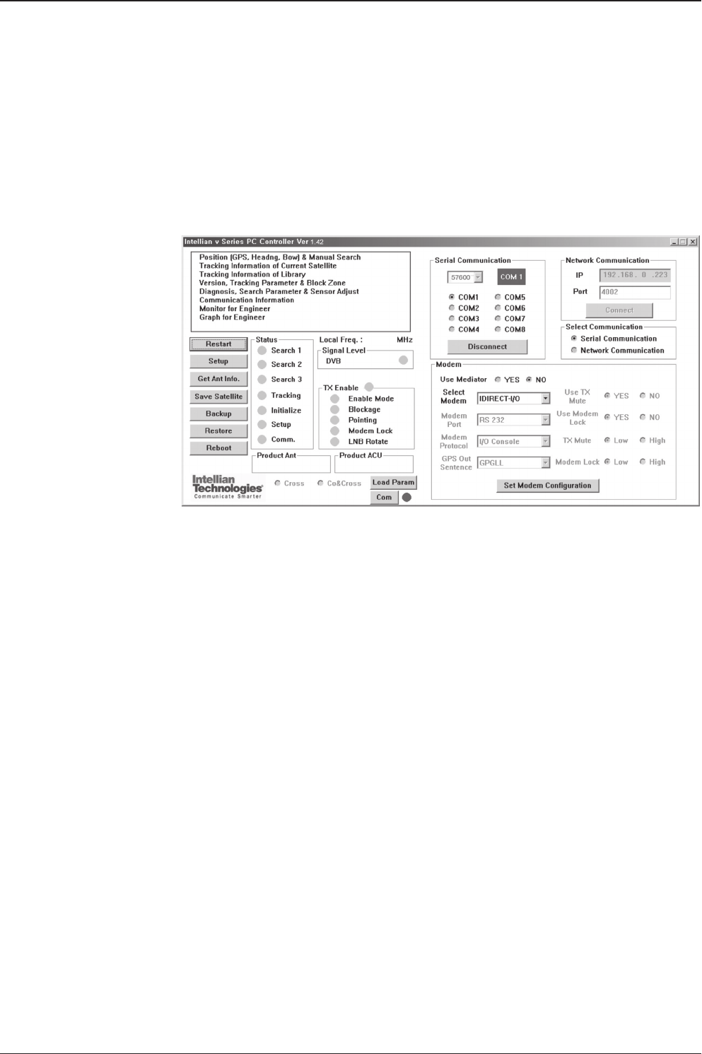
The PC Controller Software of Intellian v130 has been created for the user to easily
set up the antenna by using a personal computer.
Introduction
Antenna PC controller
77
PC CONTROLLER SOFTWARE
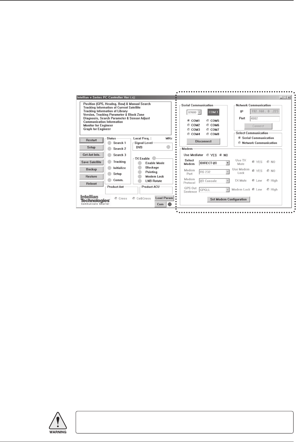
PC to ACU Communication Setup
Enter “Communication Information” menu to setup the data communication
between the PC and the ACU.
• Access ACU through Serial Communication
- Connect a 9 pin serial cable from the PC INTERFACE connector on the ACU to
the 9-pin serial port on the PC. Use USB-Serial Adapter if there is no 9-pin serial
port on the PC.
- Execute PC Controller Software by inserting the supplied CD-ROM into the CD-
ROM drive of the PC.
- The baud rate of the ACU is 19200.
- Select a COM port which is not occupied by other devices.
- Click Connect button
• Access ACU through Network Communication
- Turn off wireless connection while using this method.
- Execute PC Controller Software by inserting the supplied CD-ROM into the CD-
ROM drive of the PC.
- Enter the ACU’s IP address (Factory default IP: 192.168.0.223)
- Enter the ACU’s port number (Factory default port: 4002)
- Click Connect button
NOTE: If the remote access PC is located in the same network group with the ACU, the ACU can be
accessed through the internal IP address. But, if the remote access PC is located at the outside of
network group, the ACU’s IP address should be changed by the IP address assigned by the network
service provider. Refer to page 108 for changing the ACU’s IP address.
Establish a data
communication
WARNING: The data volume will grow very quickly if Network Communication is in use.
Intellian recommends to use Remote Web Access to access the ACU (refer to page 86).

v130 – Marine Satellite Communication System
78
• Enable the Usage of External Lock & TX Mute
- Connect a RJ45 cable from the Ethernet connector on the ACU to the modem or
connect a 9 pin serial cable from the RS232/422 connector on the ACU to the
modem.
- Select a proper data communication port (RS232/422/Ethernet) to interface with
a modem.
- Select a proper communication protocol (I/O Console/OpenAMIP/Serial GPS) to
interface with a modem.
- Enable / disable the usage of TX MUTE function.
- TX Mute is a transmit inhibit output from the ACU to disable/mute the modem
transmit through a 5 V (HIGH) or 0 V (LOW) current whenever the antenna is
blocked, searching, or is mis-pointed 0.5 degrees from peak satellite position.
This item will only be activated when the modem protocol is set as I/O Console.
- Enable/disable the usage of External Lock function. This function will only be
activated when the modem protocol is set as I/O Console.
- Modem Lock is referred that modem lock output from the modem provides a logic
input through a 5 V (HIGH) or 0 V (LOW). current to the ACU to identify when it is
on the correct satellite. This item will only be activated when the modem protocol
is set as I/O Console.
• Select GPS Out Sentence Type
- Select GPS OUT SENTENCE type (GPGLL/GPGGA/Simple GPGGA)
• Use Mediator
-Enable the usage of Mediator if the antenna is connected to the Intellian
Dual VSAT Mediator.
Disable this function if there is no Mediator connected to the ACU.
Improper setting of this parameter will cause your ACU’s modem inter
face working incorrectly.
• Select Modem
-Select a proper data communication port and protocol on the ACU to interface
with the satellite modem. The settings related to the modem interface will be set
automatically once the modem type is selected. If USER SETTING is selected, a
separate input of modem port and modem protocol is required.
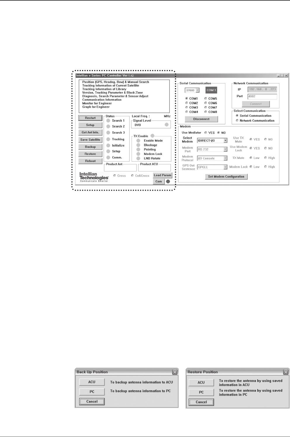
79
PC CONTROLLER SOFTWARE
Main Menu
Main menu
Restore Position Backup Position
• Controller Menus
- Position (GPS, Heading, Bow) & Manual search
- Tracking Information of Current Satellite
- Tracking Information of Library
- Version, Tracking Parameter & Block Zone
- Diagnosis, Search Parameter & Sensor Adjust
- Communication Information
• Command Buttons
- Restart: Exit SETUP mode and restart antenna.
- Setup: Enter SETUP mode.
- Get Antenna Information: Obtain the information stored in the antenna.
- Save Satellite: Save the current settings if they are able to locate the satellite (in
Tracking mode). It can reduce the satellite acquisition time after restarting the
system.
- Backup: Backup antenna information to ACU/PC.
- Restore: Restore the antenna by using saved information in ACU/PC.
- Reboot: Reboot the antenna.

v130 – Marine Satellite Communication System
80
In “SETUP” mode, “Back Up Position” or “Restore Position” message will pop up
if “Backup” or “Restore” button is pressed. Backup File (*.ibf) and Report File (*.rpt)
will be generated on the PC if “Back Up to PC” button is pressed. You can open a
report le using notepad software.
NOTE: These two functions are only available for ACU Version 1.07 or later.
• Status
- Search 1: A search pattern 1 will automatically be initiated when the ship’s heading
input does not exist or is failed. The search cycle will repeat until the antenna
receives the lock signal from the modem or the DVB transponder of the target
satellite is decoded by the antenna.
- Search 2: Search 2 is reserved for future use.
- Search 3: Search 3 is a search pattern 3 will automatically be initiated when
AGC/SIG falls below the current tracking level threshold value. Once the desired
signal is found and above the predened tracking threshold, the ACU will enter to
tracking mode.
- Tracking: Antenna is tracking the target satellite.
- Initialize: Antenna or ACU is initializing.
- Setup: Antenna is in SETUP mode.
- Comm: Antenna is able to be communicated.
• Local frequency
- Local freq: Display LNB local oscillator frequency.
- Signal level: Display signal level. It shows “DVB” when DVB mode of tracking
signal is chosen to be used and “NBD” when NBD mode of tracking signal is
chosen to be used.
• System versions
- Product ant: Display antenna model and “PCU” rmware version.
- Product ACU: Display ACU model and “ACU main” rmware version.
• TX enable:
- TX enable: TX function is enabled and ready to transmit.
- Enable mode: Not in SETUP mode.
- Blockage: Antenna is not facing the predened block zone(s).
- Pointing: Antenna is pointing to the target satellite.
- Modem lock: Satellite modem is sending a logic input to the ACU to identify when
the antenna tracks on the correct satellite.
- LNB rotate: LNB is not rotating.
NOTE: The TX function will be enabled (shows blue dot) only if all of the factors listed above shows “blue”
dot. If any of the factors listed above shows “gray” dot or "red" dot, the TX function will be disabled
(shows red dot).
Exception: If “Use TX Mute” is set as “NO”, the TX function will be enabled regardless of which factor
listed above shows “gray” dot or “red” dot.
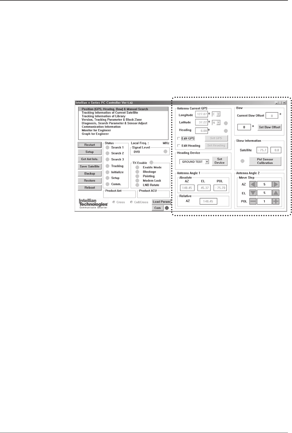
81
PC CONTROLLER SOFTWARE
Position & Manual Search
Set the GPS and ship’s heading information to acquire the satellite signal and use
move step function to nd the satellite signal manually.
Antenna angle, GPS and
ship’s heading information
Antenna Current GPS
- Antenna Current GPS: Display current antenna GPS and Ship’s heading
information. Enter SETUP mode and click check box in front of Edit GPS/Edit
Heading to set GPS / ship’s heading. After the desired value is entered press Set
GPS/Set Heading button to save the settings.
- Set GPS: Set antenna GPS information manually.
- Set Heading: Set ship’s heading information manually.
Heading Device
- Heading Device: Set ship’s heading device and its baudrate
(4800/9600/19200/38400).
Antenna Angle 1
- Antenna Angle 1: Display current antenna absolute and relative AZ (azimuth)
position, EL (elevation) position and LNB pol angle.
Bow
- Bow: Display and set bow offset if needed.
Skew Information
- LNB pol Information: Display LNB pol angle and satellite skew angle.
- Pol sensor calibration: Calibrate the sensor (potentiometer).
Antenna Angle 2
- Antenna Angle 2: Move antenna azimuth and elevation position and LNB pol angle
to nd the desired satellite manually.
Controller Menus
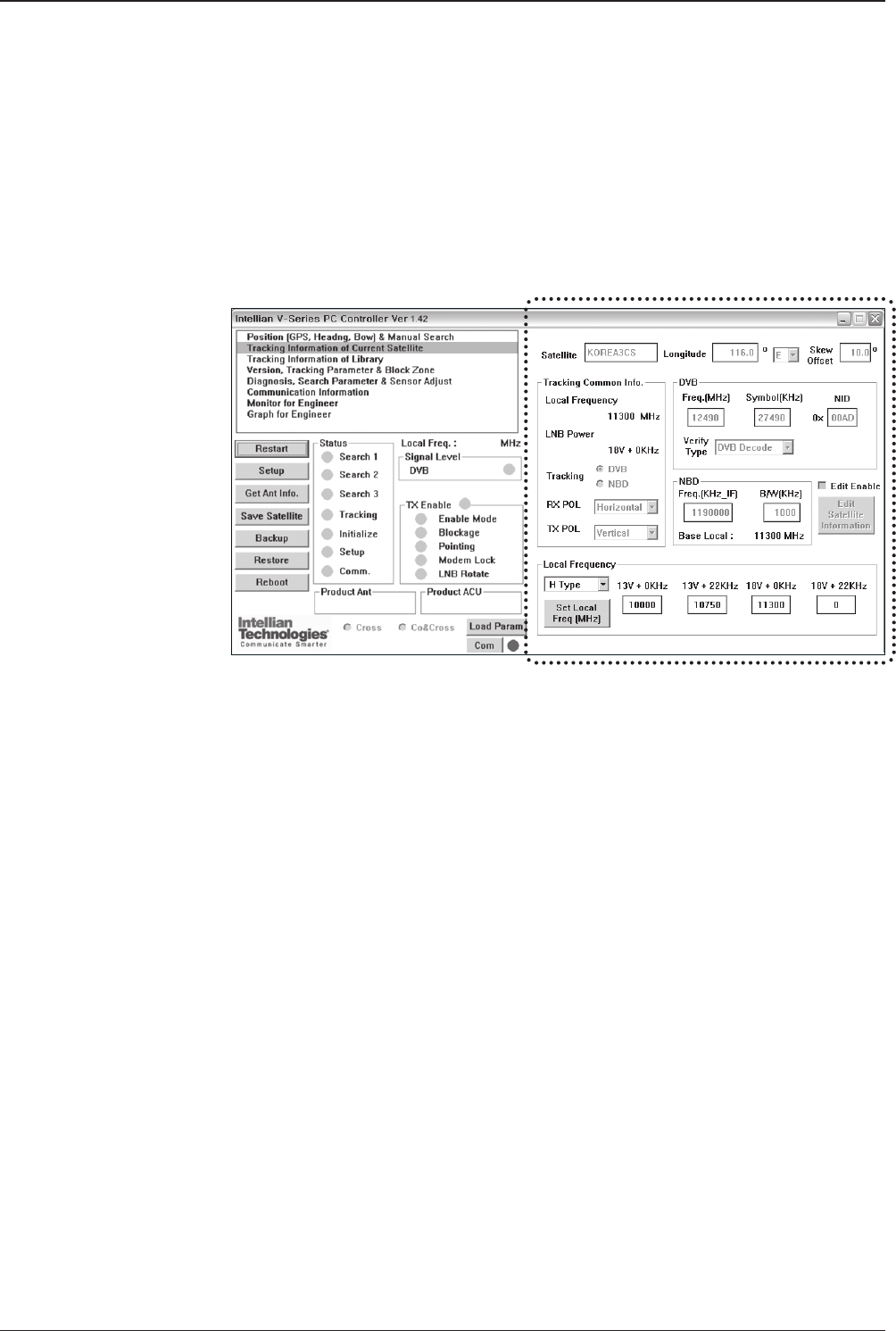
v130 – Marine Satellite Communication System
82
Tracking Information of Current Satellite
Set the tracking mode and tracking frequency of the current satellite.
Set the LNB local frequency to its corresponding voltage power supply.
Satellite Information
- Satellite information: Display the current satellite name, longitude position and
satellite skew.
Tracking Common Info
- Local Frequency & LNB Power: Display the current LNB frequency which is in use
and its corresponding voltage power supply.
- Tracking: Display/ set the current tracking mode (DVB/ NBD).
- RX POL and TX POL: Set RX and TX polarity (Vertical/Horizontal).
DVB
- DVB: Set satellite tracking information (frequency, symbol rate, NID and verify
type) for DVB tracking mode.
NBD
- NBD: Set satellite tracking information (frequency and bandwidth) for NBD tracking
mode.
Local Frequency
- Local frequency: Display or set LNB local frequency and its corresponding LNB
power supply.
NOTE: Select the Swedish Microwave (SMW) PLL LNB type from the Drop-Down List. If the LNB type is
other than SMW, manually input the LNB local frequency is required.
Set the current satellite
tracking information
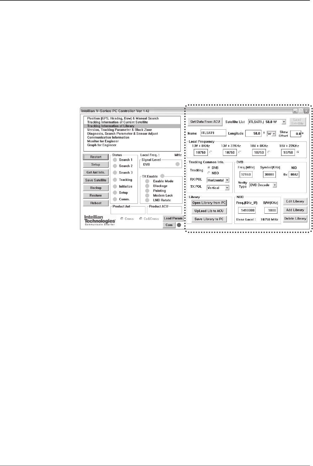
83
PC CONTROLLER SOFTWARE
Tracking Information of Library
Open the pre-programmed satellite library le and upload it to the ACU.
Build your own custom library and save it to an external hard drive/PC.
Get data from ACU
- Get data from ACU: Obtain the pre-programmed satellite library le from the ACU
while the antenna is in SETUP mode.
Load Satellite
- Load satellite: Upload the pre-programmed satellite information in the library.
Library
- Open library from PC: Open the satellite library le from the supplied Intellian CD
or from the external hard drive/PC. (File format: *.ilf)
- Upload library to ACU: Upload the satellite library le to ACU.
- Save library to PC: Save the current library setting to the PC.
- Edit Library: Edit the satellite information of the selected satellite.
- Add Library: Add the satellite information as dened in the current settings.
- Delete Library: Delete the selected satellite from the library settings.
NOTE: It is required to click the “Save Library to PC” button after “Edit Library”, “Add Library “, or “Delete
Library” button is clicked. These functions are only available for ACU Version 1.07 or later.
Library information

v130 – Marine Satellite Communication System
84
Version, Tracking Parameter & Block Zone
Display the antenna, ACU rmware versions and serial number.
Setup the antenna blockage zone(s).
Setup the antenna parameters.
Display antenna versions
and tracking parameters
Software Information
- Software information: Display antenna and ACU rmware versions and library
version.
Product Information
- Product information: Display antenna and ACU serial numbers.
Parameter Setting
- DVB: Display /setup current detect level threshold and tracking level threshold
when DVB tracking mode is chosen to be used.
- NBD: Display /setup current detect level threshold and tracking level threshold
when NBD tracking mode is chosen to be used.
- TX Enable Threshold: display/ setup TX enable threshold.
Block Zone
- Display current block zones by azimuth and elevation sectors. Up to 5 blockage
zones can be programmed.
NOTE: DVB and NBD parameter settings should only be changed by an authorized service technician.
Improper setting of these parameters will render your system inoperable. Consult Intellian for changing
antenna parameters.
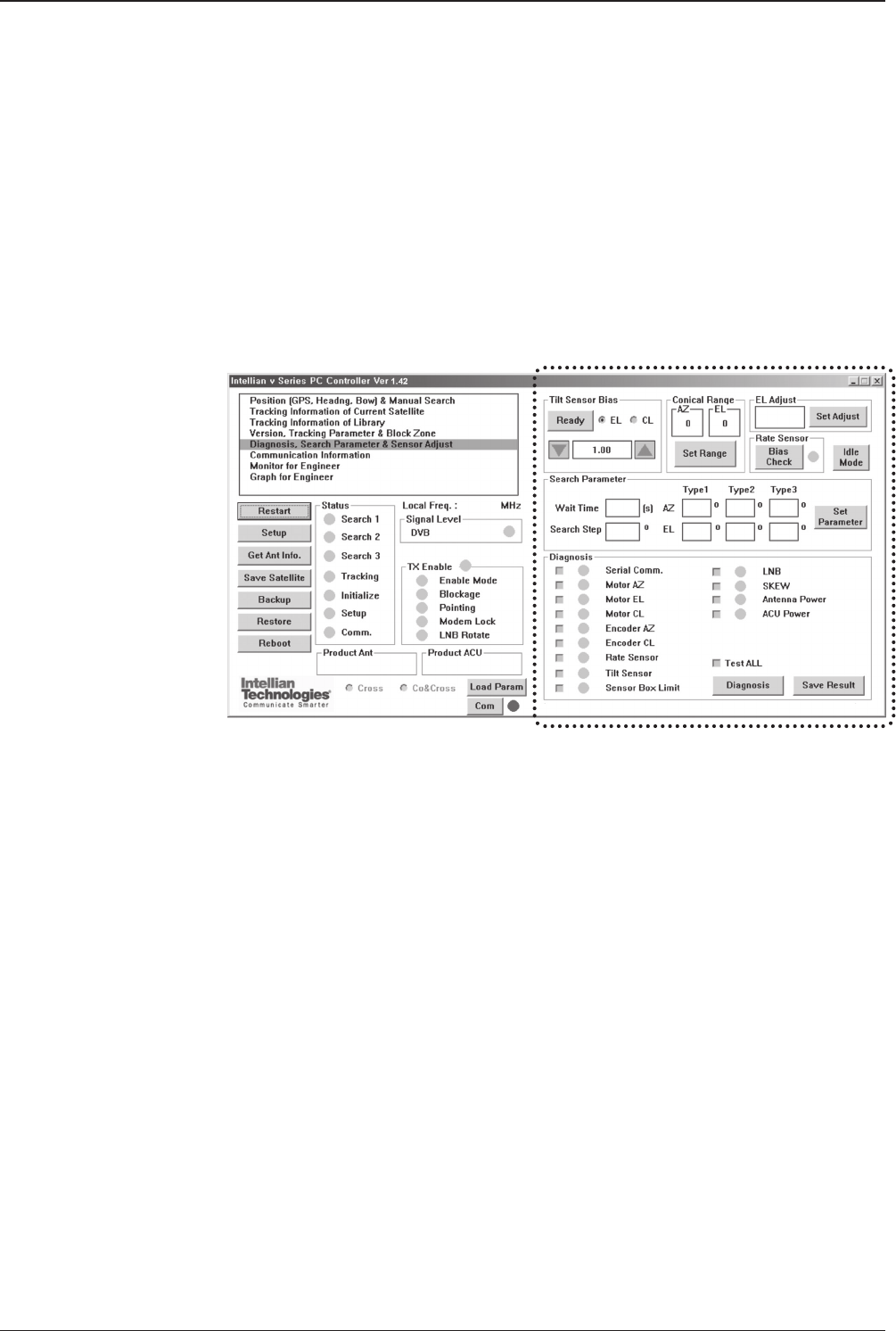
85
PC CONTROLLER SOFTWARE
Display antenna versions
and parameters
Tilt Sensor Bias
- Tilt sensor bias: Adjust the two solid-state tilt sensors used to provide absolute
cross-level tilt of the antenna and elevation feedback to eliminate long-term
pointing drift (error). Tilt bias is required to be adjusted when the antenna control
board or sensor box is replaced. Check and see if the bubble is located at the
center of the level vial.
- Ready: Make elevation angle go to 0º for tilt sensor bias adjustment.
Conical Range
- Conical rage: set conical range while the antenna is on tracking mode.
EL Adjust
- EL adjust: The elevation adjustment is to offset the angle difference between the
mechanical elevation angle and actual elevation angle.
Diagnosis, Search Parameter & Sensor Adjust
Set the tilt sensors and calibrate rate sensors.
Set the antenna search parameters.
Run an antenna diagnostic test.

v130 – Marine Satellite Communication System
86
Rate Sensor
- Rate sensor: Rate sensor is to calibrate DC voltage output from the three rate
sensors used to sense antenna motion in azimuth, elevation and cross-level axes.
The DC voltage output from each of the rate sensors may be vary by an amount
which is directly proportional to the direction and rate of motion induced on it..
Before calibrating the rate sensors located at the Sensor box, make sure that the
antenna is placed on a rigid and at platform. During the calibration process, the
antenna should avoid any motion as it can affect the antenna’s performance. After
clicking the “Rate Sensor Bias Check” button, the green dot will be displayed as
a ready signal to calibrate the gyro sensor. The red dot (fail) or blue dot (pass) will
be displayed once the calibration is completed.
Idle Mode
- Idle mode: Release the elevation and cross level motor brakes while the antenna
is in SETUP mode. The antenna can be moved manually during the idle mode.
Diagnosis
- Diagnosis: The system can carry out the selected full diagnostic test “Test All” or
single diagnostic test. The software will display the diagnostic results Blue dot
represents “normal”, red represents “abnormal”, yellow represents “skip test” and
green represents “the diagnostic test is under process”.

87
REMOTE WEB ACCESS
REMOTE WEB ACCESS
Introduction
Main Page
Antenna Settings
General Information
Current Status
Ship Information
Antenna Position
Tracking Information
Parameter Setting
Modem Setting
Block Zone Setting
Diagnosis
Satellite Information
Antenna/ACU Firmware Upgrade
Firmware Upgrade
Roll Back
Upgrade Log
Ethernet-to-Serial Settings
Network Setting
Serial Setting
SNMP Setting
Change Password
Upgrade E2S (Ethernet-to-Serial)
Save & Reboot
Access Log
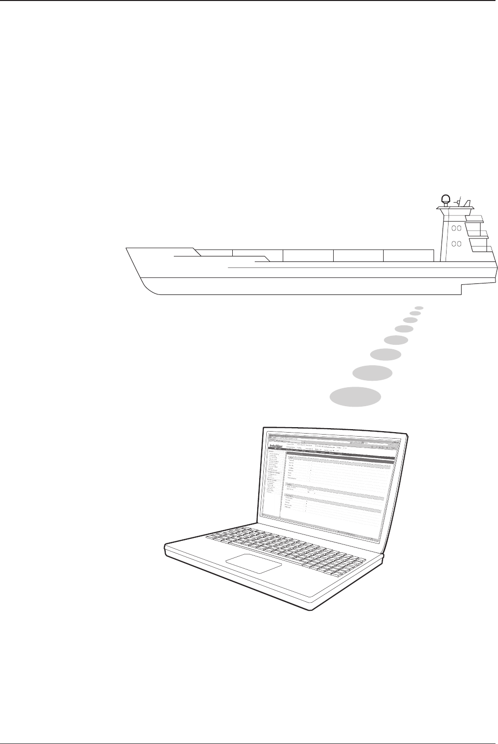
v130 – Marine Satellite Communication System
88
Introduction
With embedded remote access function, the v-Series can be monitored, controlled,
and diagnosed remotely from anywhere, anytime through the TCP/IP protocol.
This not only can save tremendous time but also save the cost generated from the
hundreds of routine maintenance activities such as operating rmware upgrades,
tracking parameters resets, and system diagnostic.

89
REMOTE WEB ACCESS
• Page Login
1. Enter the ACU's IP address into your web browser's address bar to login into
the ACU’s internal HTML page. If this system has not been changed from the
ACU’s factory default:
IP address: Primary: 192.168.0.223
Secondary: 10.10.1.1
2. Choose either to Control & Monitor the ACU or Only Monitor the ACU.
3. Log into the ACU by typing in User Name and Password information. If this
system has not been changed from the factory default:
User Name: intellian
Password: 12345678
Main Page
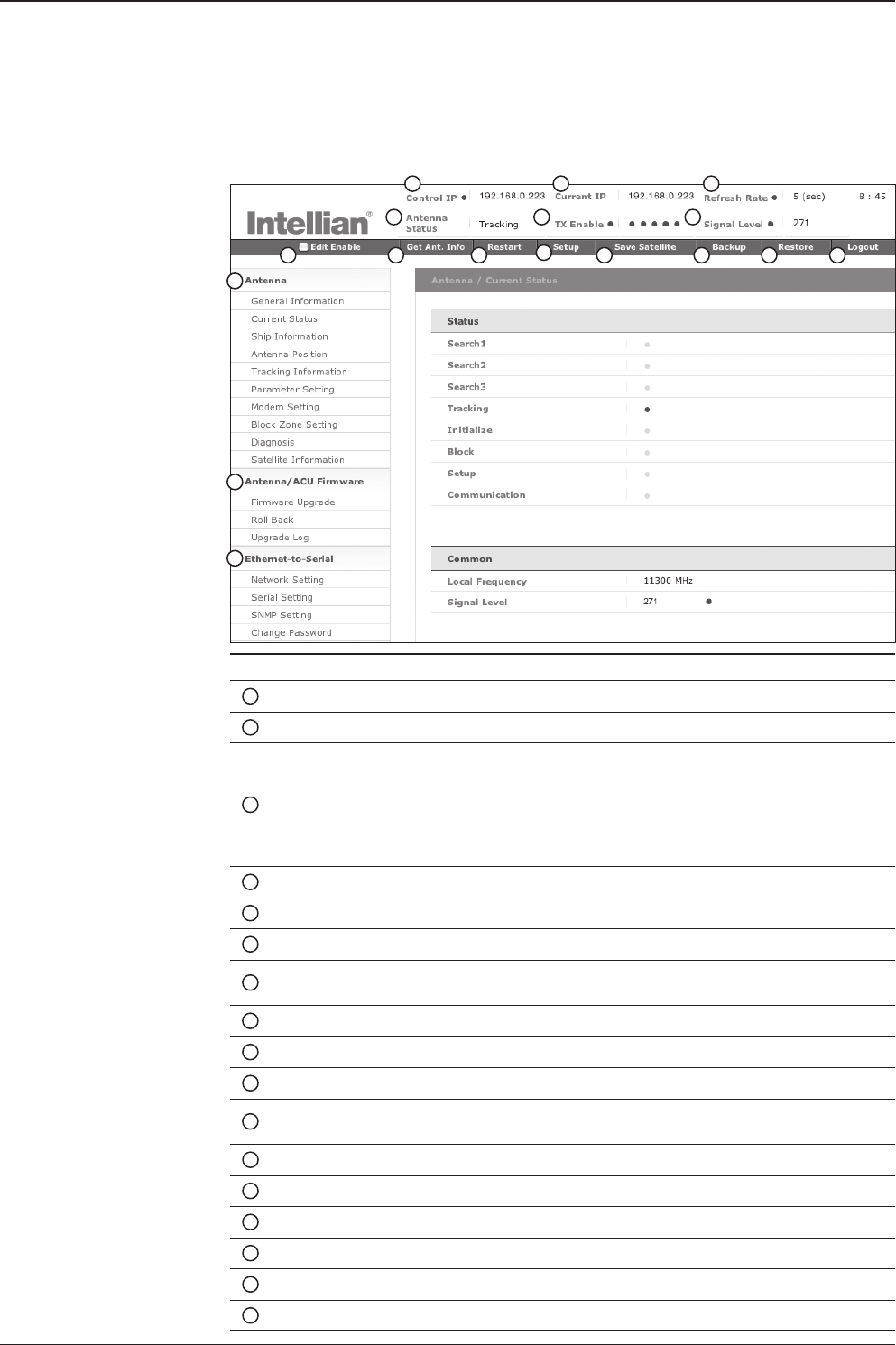
v130 – Marine Satellite Communication System
90
No. Item Description
1Control IP Display current IP that controls the ACU.
2Current IP Display current IP address.
3Refresh Rate
Display screen refresh rate and time out.
The screen will not refresh once the time-out shows 0:00.
Exception: If the Refresh Disable Time is set to “OFF” in the
Network Setting page, then the clock will show “--:--“ and
system will keep monitoring all activities regardless of time-
out.
4Antenna Status Display antenna status.
5TX Enable
Display whether or not the antenna is able to transmit the data.
6Signal Level Display current signal level.
7Edit Enable Enable to edit the ACU settings. Ensure the check box is
enabled before modifying the settings.
8Get Antenna Info Obtain current antenna information.
9Restart Restart antenna system.
10 Setup Enter SETUP mode.
11 Save Satellite Save current satellite settings.
Bow offset will be adjusted and saved automatically.
12 Backup Backup antenna information to ACU.
13 Restore Restore antenna information from ACU.
14 Logout Logout ACU’s internal HTML page.
15 Antenna Antenna setup menu.
16 Firmware Firmware upgrade menu.
17 Ethernet-to-Serial ACU’s IP address and serial communication setup menus.
1 2 3
45 6
7 8 9 10 11 12 13 14
15
16
17
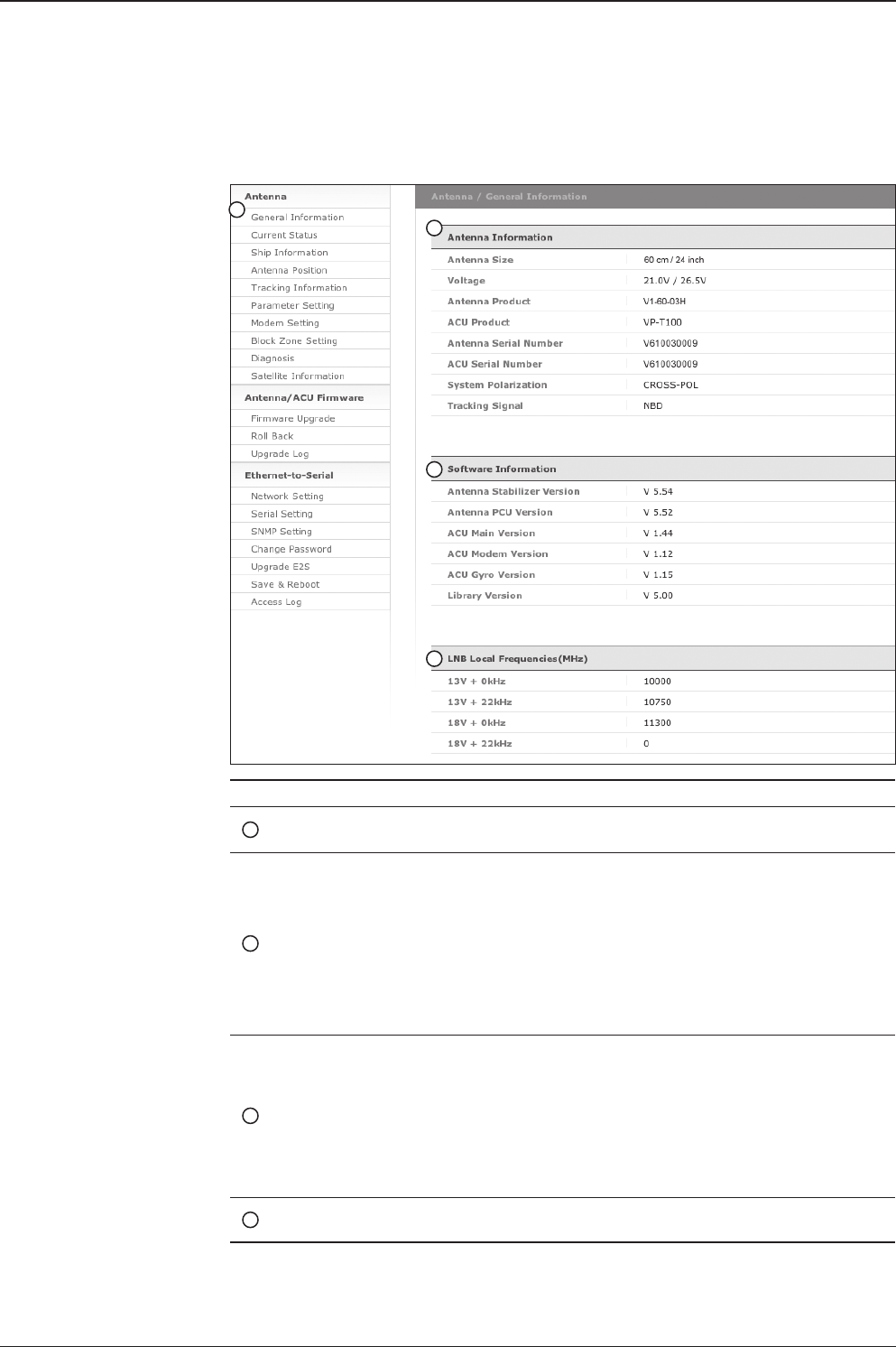
91
REMOTE WEB ACCESS
No. Item Description
1General
Information Display current antenna information.
2Antenna
Information
Display current antenna information.
- Antenna Size: antenna dish size.
- Voltage: operation voltage of antenna and ACU.
- Antenna Product: antenna model number.
- ACU Product: ACU model number.
- Antenna Serial Number: antenna serial number.
- ACU Serial Number: ACU serial number
-
System Polarization: antenna polarized feed (Crosspol/Copol).
- Tracking Signal: satellite tracking mode (DVB/NBD)
3Software
Information
Display current Antenna and ACU rmware versions and
Satellite Library version installed in the system.
- Antenna Stabilizer Version
- Antenna PCU Version
- ACU Main Version
- ACU Modem Version
- ACU Gyro Version
- Library Version
4LNB Local
Frequencies(MHz)
Display LNB local frequency and corresponding voltage.
Antenna Settings
General Information
1
2
3
4
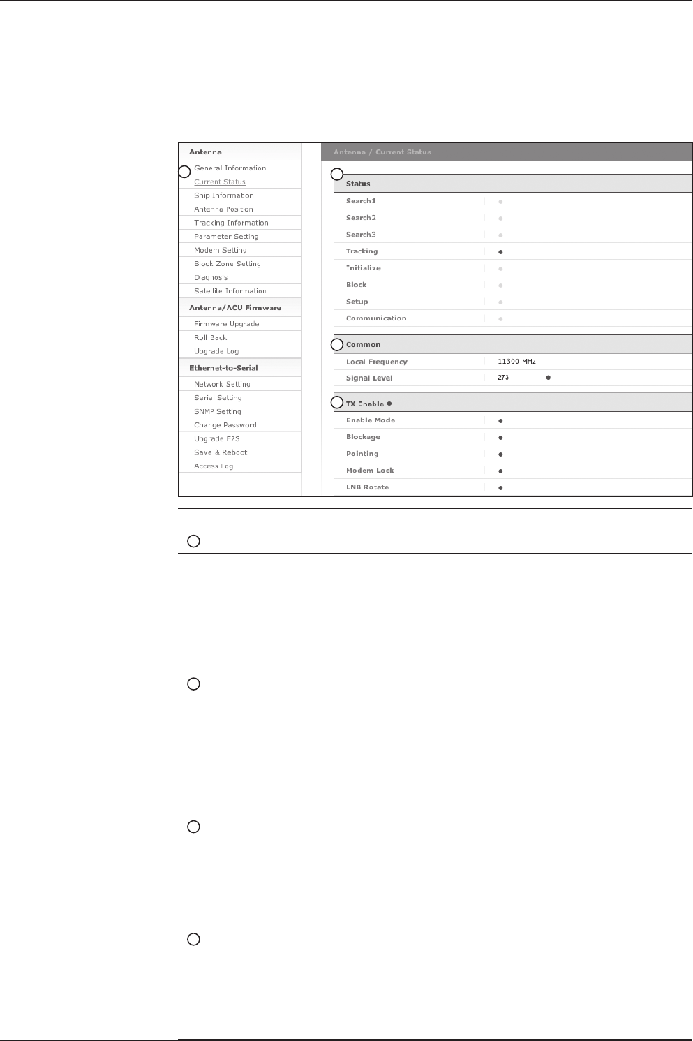
v130 – Marine Satellite Communication System
92
Current Status
No. Item Description
1Current Status Display current antenna status.
2Status
Display current antenna status.
- Search 1: a search pattern 1 will automatically be initiated
when the ship’s heading input does not exist / is failed. The
search cycle will repeat until the antenna receives the lock
signal from the modem or the DVB transponder of the target
satellite is decoded by the antenna.
- Search 2: is reserved for future use.
- Search 3: a search pattern 3 will automatically be initiated
when AGC/SIG falls below the current tracking level
threshold value. Once the desired signal is found and above
the predened tracking threshold, the ACU will enter to
tracking mode.
- Tracking: antenna is tracking the target satellite.
- Initialize: antenna or ACU is initializing.
- Block: satellite signal is being blocked.
- Setup: antenna is in SETUP mode.
- Communication: antenna is able to be communicated with ACU.
3Common Display current LNB local frequency and signal level.
4TX Enable
Display whether or not the antenna is able to transmit the
data. The TX function will only be enabled (shows BLUE dot)
only if all of the factors listed below shows “BLUE” dot.
Exception: If “Use TX Mute” is set as “NO”, the TX function
will be enabled regardless of which factor listed below shows
“gray” dot or “red” dot.
- Enable Mode: antenna is not in SETUP mode.
- Blockage: antenna is not facing the predened block zone(s).
- Pointing: antenna is pointing to the target satellite.
- Modem Lock: satellite modem is sending a logic input to
the ACU to identify when the antenna tracks on the correct
satellite.
- LNB Rotate: LNB is not rotating.
2
12
3
4

93
REMOTE WEB ACCESS
Ship Information
No. Item Description
1Ship Information Display GPS and ship’s gyro information.
2GPS
Display current GPS information.
- Longitude (East/West)
- Latitude (North/South)
3BOW Offset Display and set bow offset if needed.
4Heading Device
Current device: set ship’s heading device.
If the ship’s gyro input is Step-by-step (SBS) separate
purchase of GYRO Converter is required.
- Heading: set ship’s heading information.
1
2
3
4
WARNING: Ensure the Edit Enable check box is enabled before modifying the settings.
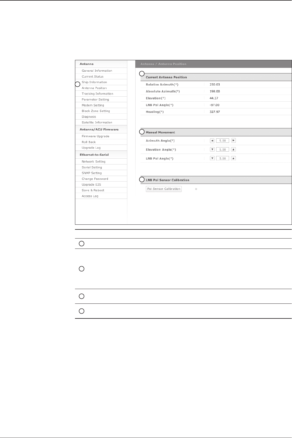
v130 – Marine Satellite Communication System
94
Antenna Position
No. Item Description
1Antenna Position Display current antenna position.
2Current Antenna Position
Display current antenna position.
-
Relative Azimuth: display antenna relative AZ angle.
-
Absolute Azimuth: display antenna absolute AZ angle.
- Elevation: display antenna elevation angle.
- LNB Pol Angle: display LNB pol angle.
- Heading: display ship’s heading information.
3Manual Movement Move antenna azimuth and elevation angles and
LNB pol angle to nd the desired satellite manually.
4LNB Pol Sensor Calibration Calibrate the LNB pol angle when the control board,
potentiometer or belt is replaced.
1
2
3
4
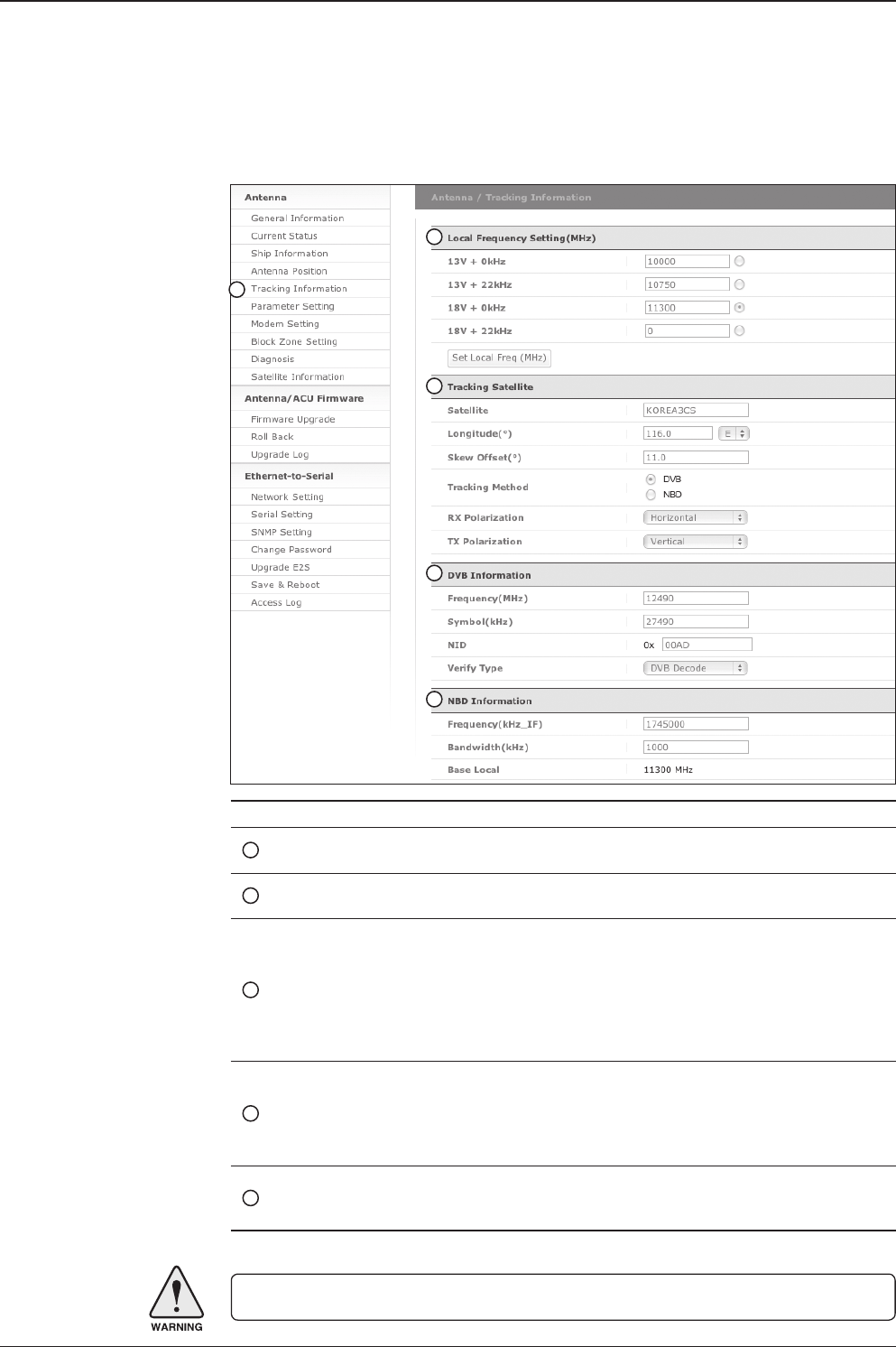
95
REMOTE WEB ACCESS
Tracking Information
No. Item Description
1
Tracking Information
Display or set current tracking mode and tracking frequency of
the target satellite.
2Local Frequency
Setting (MHz)
Display LNB’s local frequencies. Display current LNB local
frequency which is in use and voltage.
3Tracking Satellite
Display current tracking mode.
- Satellite: display satellite name.
- Longitude: display satellite orbit position.
- Skew Offset: display Skew offset.
-
Tracking Method: display current tracking mode (DVB/NBD).
- RX Polarization: display current RX polarization.
- TX Polarization display current TX polarization.
4DVB Information
Display DVB tracking mode’s tracking information.
- Frequency: display tracking frequency.
- Symbol rate: display symbol rate.
- NID: display network ID.
-
Verify type: display verication type (AGC, DVB, DVB Decode)
5NBD Information
Display NBD tracking mode’s tracking information.
- Frequency: display tracking IF frequency.
- Bandwidth: display detection bandwidth.
1
2
3
4
5
WARNING: Ensure the Edit Enable check box is enabled before modifying the settings.
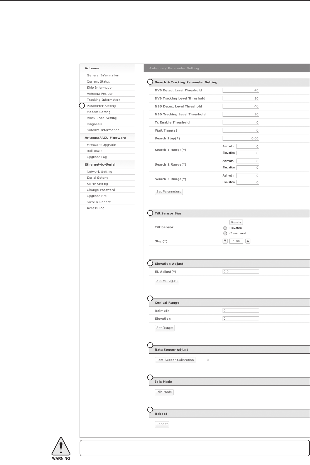
v130 – Marine Satellite Communication System
96
Parameter Setting
1
2
3
4
5
6
7
8
WARNING: Ensure the Edit Enable check box is enabled before modifying the settings.

97
REMOTE WEB ACCESS
No. Item Description
1Parameter Setting
Set antenna search & tracking parameters.
These parameters should only be changed by an authorized
service technician. Improper setting of these parameters will
render your system inoperable.
2Search & Tracking
Parameter Setting
DVB Detect and Tracking Level Threshold: display/set current
detect level threshold and tracking level threshold when DVB
tracking mode is chosen to be used.
- NBD Detect and Tracking Level Threshold: display/set
current detect level threshold and tracking level threshold
when NBD tracking mode is chosen to be used.
- Enable Threshold: display/set TX enable threshold.
- Wait time: set the time-out for automatic initiation of a search
after the signal level drops below the pre-dened threshold
value.
- Search Step: set increment step size.
- Search 1 & 3 Range: set Search 1 & 3 search range. Search
is conducted in a two-axis pattern consisting of alternate
movements in azimuth and elevation as forming expanding
square.
- Search 2 Range: is reserved for future use.
3Tilt Sensor Bias
Adjust the two solid-state tilt sensors used to provide absolute
cross-level tilt of the antenna and elevation feedback to
eliminate long-term pointing drift (error). Tilt bias is required to
be adjusted when the antenna control board or sensor box is
replaced. Check to see whether or not the bubble is located at
the center of the level vial.
4Elevation Adjust Adjust the angle difference between the mechanical elevation
angle and actual elevation angle.
5Conical Range Set conical range while the antenna is on tracking mode.
6Rate Sensor
Adjust
Calibrate DC voltage output from the three rate sensors used
to sense antenna motion in azimuth, elevation and cross-level
axes. During the calibration process, the antenna should avoid
any motion as it can affect the antenna’s performance.
7Idle Mode
Release the elevation and cross level motor brakes while
the antenna is in SETUP mode. The antenna can be moved
manually during the idle mode.
8Reboot Reboot the system.
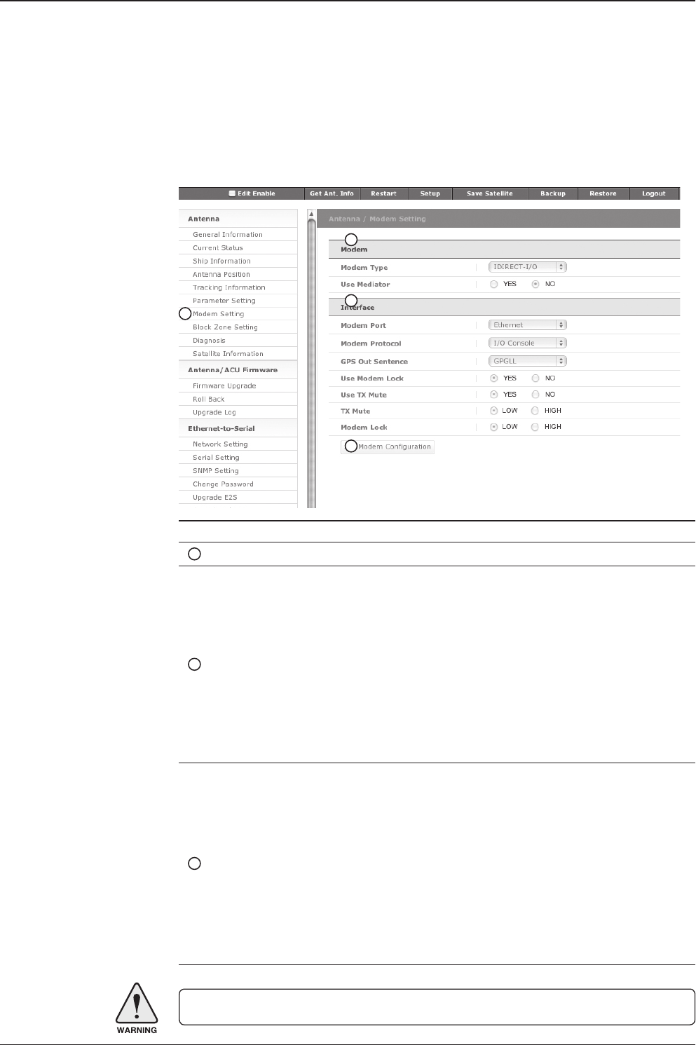
v130 – Marine Satellite Communication System
98
Modem Setting
No. Item Description
1Modem Setting Set the modem interface.
2Modem
- Modem Type: is to select a proper data communication port
and protocol on the ACU to interface with the satellite modem.
The settings related to the modem interface will be set auto-
matically once the modem type is selected (USER SETTING,
IDIRECT-I/O, IDREICT-AMIP, COMTECH-I/O, COMTECH-
ROSS, SATLINK). However, it is required to set Item “Inter-
face” separately if USER SETTING is selected.
- Use Mediator: enable the usage of Mediator if the antenna is
connected to the Intellian Dual VSAT Mediator. Use Mediator
must be set to “NO” if there is no MEDIATOR connected to the
ACU. Improper setting of this parameter will cause your ACU’s
modem interface working incorrectly.
3Interface
- Modem Port: is to select a proper data communication port
on the ACU to interface with the satellite modem (RS232/422/
Ethernet).
- Modem Protocol: is to select a proper communication protocol
on the ACU to interface with the modem (I/O Console,
OpenAMIP, Serial GPS, ROSS)
- GPS Out Sentence: is to select the GPS out sentence type
(GPGLL/GPGGA/SIMPLE GPGGA)
- USE Modem Lock: is to select whether or not to use external
lock signal from the satellite modem.
- USE TX Mute: is to select whether or not to use TX mute
function from the satellite modem.
WARNING: Ensure the Edit Enable check box is enabled before modifying the settings.
1
2
3
4

99
REMOTE WEB ACCESS
- TX Mute: is a transmit inhibit output from the ACU to disable/
mute the modem transmit through a 5V (High) or 0V(LOW)
current whenever the antenna is blocked, searching, or is mis-
pointed 0.5° from peak satellite position.
- Modem Lock: is the modem lock output from the modem
provides a logic input through a 5V (High) or 0V(LOW) current
to the ACU to identify when it is on the correct satellite.
Note: TX Mute and Modem Lock items will only be activated
when the modem protocol is set as I/O Console.
4Set Modem
Conguration -Conrm to congure your modem settings.
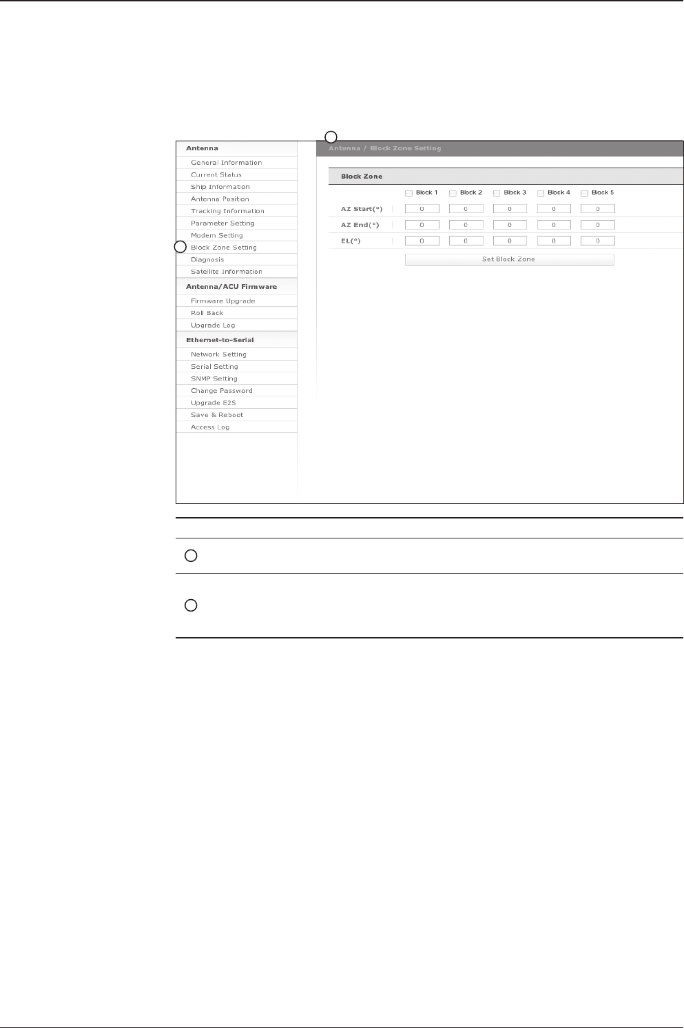
v130 – Marine Satellite Communication System
100
Block Zone Setting
No. Item Description
1Block Zone
Setting Up to 5 block zones are allowed to be programmed.
2Block Zone
This is the clockwise of the two points. AZ. START is where the rela-
tive azimuth starts and AZ. END is where the relative azimuth ends
(Range: 0 - 360°). EL. Limit is where the elevation starts (Range 0
- 90°).
1
2
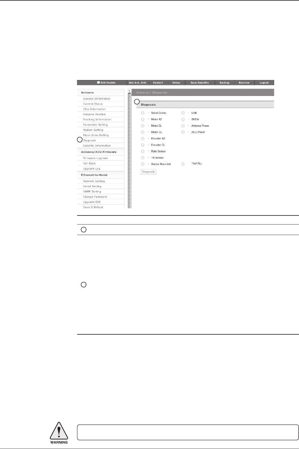
101
REMOTE WEB ACCESS
Diagnosis
No. Item Description
1Diagnosis Execute antenna diagnostic test.
2Diagnosis
Select to run a full diagnostic test or single diagnostic test.
- Serial Comm.: test the data communication between the
antenna and the ACU.
- Motor AZ: test the azimuth motor.
- Motor EL: test the elevation motor.
- Motor CL: test the cross-level motor.
- Encoder AZ: test the azimuth encoder.
- Encoder CL: test the cross-level encoder.
- Gyro Senor: test the gyro sensor.
- Tilt Sensor: test the tilt sensor.
- Sensor Box Limit: test the sensor box motor.
- LNB: test the LNB.
- LNB pol: test the LNB pol motor.
- Antenna Power: test the antenna power.
- ACU Power: test the ACU power.
WARNING: Ensure the Edit Enable check box is enabled before modifying the settings.
1
2

v130 – Marine Satellite Communication System
102
Satellite Information
1
2
3
4
5
6
7

103
REMOTE WEB ACCESS
No. Item Description
1Satellite
Information Display the satellite library information.
2Get Satellite Info
from ACU Obtain satellite information installed in the ACU.
3Library
- Open Library from PC: open the satellite library le from the
supplied Intellian CD or from the external hard drive/PC. (File
format: *.ilf)
- Upload Library to ACU: upload the satellite library le to ACU.
- Save as Library to PC: save the current library setting to the
PC.
4Load Satellite Select satellite that you wish to track and press Load button to
load the selected satellite.
5Tracking Satellite
- Satellite: display satellite name.
- Longitude: display satellite orbit position.
- Skew offset: display Skewoffset.
- Tracking method: display current tracking mode (DVB/NBD)
- RX polarization: display current RX polarization.
- TX polarization: display current TX polarization.
6DVB Information
- Display DVB tracking mode's tracking information.
- Frequency: display tracking frequency.
- Symbol rate: display symbol rate.
- NID: display network ID.
- Verify type: display verication type (AGC only, DVB lock,
DVB decode, DSS decode)
7NDB Information
Display NBD tracking mode's tracking information.
- Frequency: display tracking frequency.
- Bandwidth: display detection bandwidth.
8Local Frequency
Setting Display LNB local frequency (MHz) and voltage.
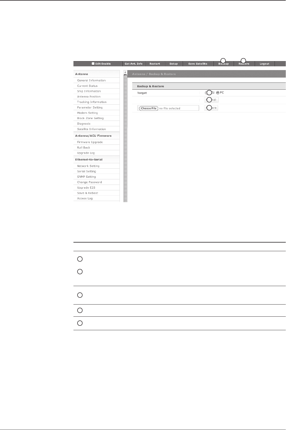
v130 – Marine Satellite Communication System
104
Backup & Restore
No. Item Description
1
2
Backup
Restore Enter Backup & Restore page. (Setup mode is required)
3Target Backup antenna information to ACU/PC or Restore antenna by
using the saved information ACU/PC.
4Backup Backup antenna information.
5Restore Restore antenna information.
1 2
3
4
5

105
REMOTE WEB ACCESS
Antenna/ ACU Firmware Upgrade
Firmware Upgrade
No. Item Description
1Firmware Upgrade Upgrade antenna and ACU rmware version.
Browse and select the rmware package le to upload.
Upgrade Steps
1. Select the upgrade package le.
2. Click on “Start Upload” button to transfer the Firmware package le (“*.fwp”) to
E2S (Ethernet to serial) module.
3. After the package le is transferred, it will show “upgrade from vx.xx Version to
vx.xx Version." Enable the check box to select the rmware le that you wish to
upgrade.
4. Click on “Start Upgrade” button.
1
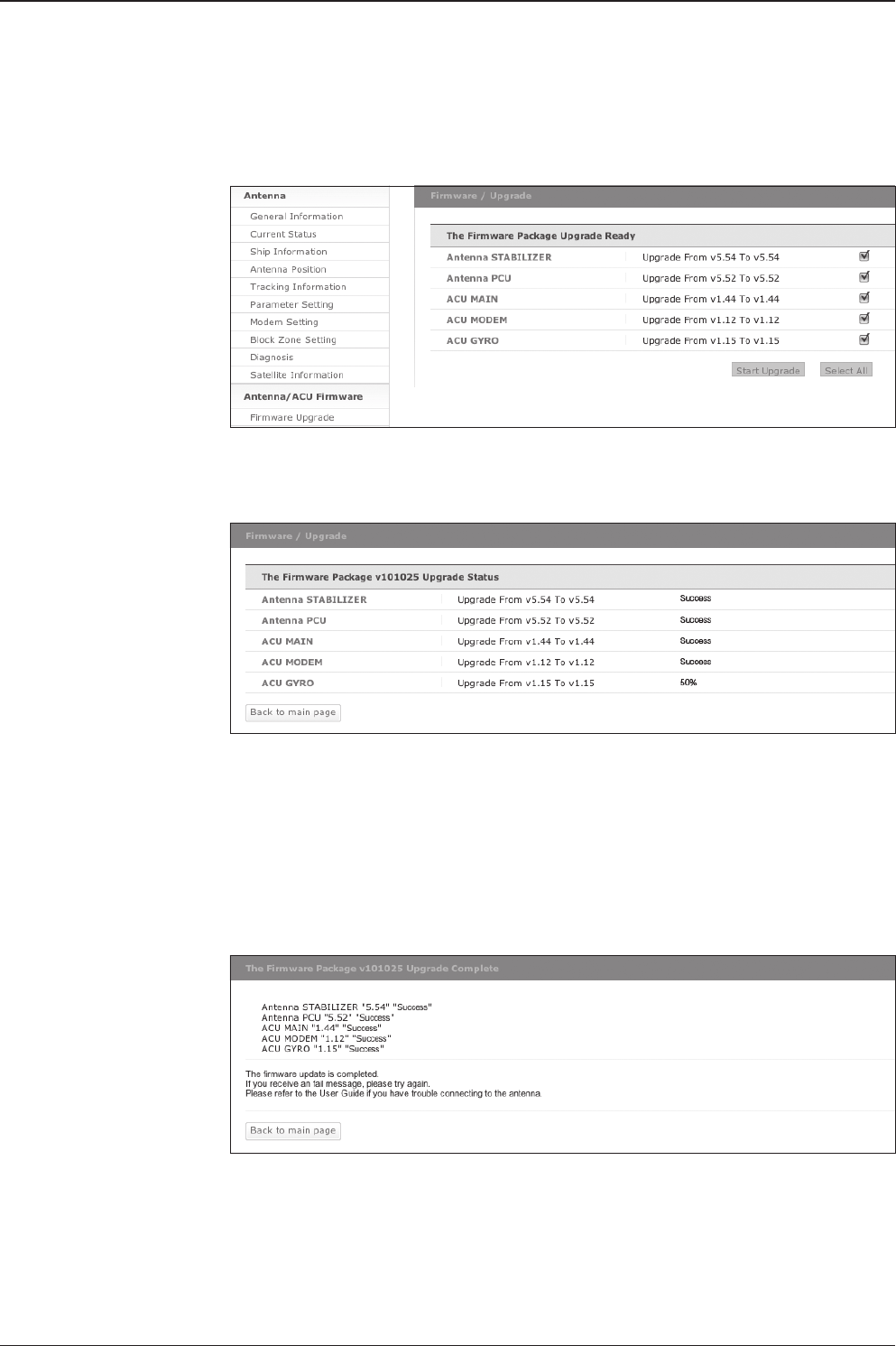
v130 – Marine Satellite Communication System
106
5. It will display information about the upgrade process status on full
screen.
Firmware upgrade
status page
Upgrade process
status page
6. If the rmware is successfully upgraded, it will display “The rmware update is
completed.”
7. Click on "Back to main page" to go out of the screen.
To verify the upgraded rmware version, go to the right-side menu of "General
information"
Upgrade
complete page

107
REMOTE WEB ACCESS
Roll Back
No. Item Description
1Roll Back Roll back antenna and ACU rmware to previous package version
or latest package version.
1
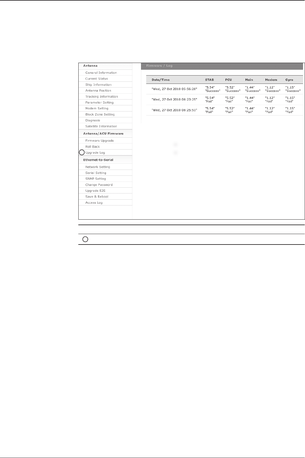
v130 – Marine Satellite Communication System
108
Upgrade Log
No. Item Description
1Upgrade Log Display log information of rmware upgrade.
1
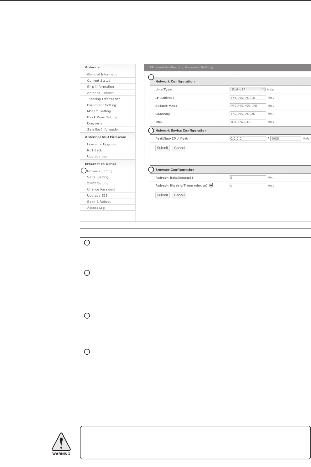
109
REMOTE WEB ACCESS
WARNING: Enter Save & Reboot page and click on “Save & Reboot” button after
completing the modication of Ethernet-to-Serial’s settings. Without doing so, the
modied settings will be lost.
Ethernet-to-Serial Settings
Network Setting
No. Item Description
1Network Setting Modify ACU’s Internal IP address.
2Network Conguration
Modify ACU’s Internal IP address and press Submit
button. Go to “Save & Reboot” page and press Save &
Reboot button to validate the changes.
- IP Address: Factory default
(Primary: 192.168.0.223)/(Secondary: 10.10.1.1)
- Subnet Mask: Factory default (255.255.255.0)
- Gateway (modem IP): Factory default (192.168.0.254)
3Network Service
Conguration
Install the PortView software to use this function.
Setup the IP address and socket number to the PC
installed with PortView software.
PortView function will not be activated if the IP address is
set to 0.0.0.0.
4Browser Conguration
Modify browser refresh rate and refresh disable time.
If the check box of Refresh Disable Time is enabled,
then Refresh Disable Time function will be activated and
system will keep monitoring all activities regardless of
time-out.
1
2
3
4
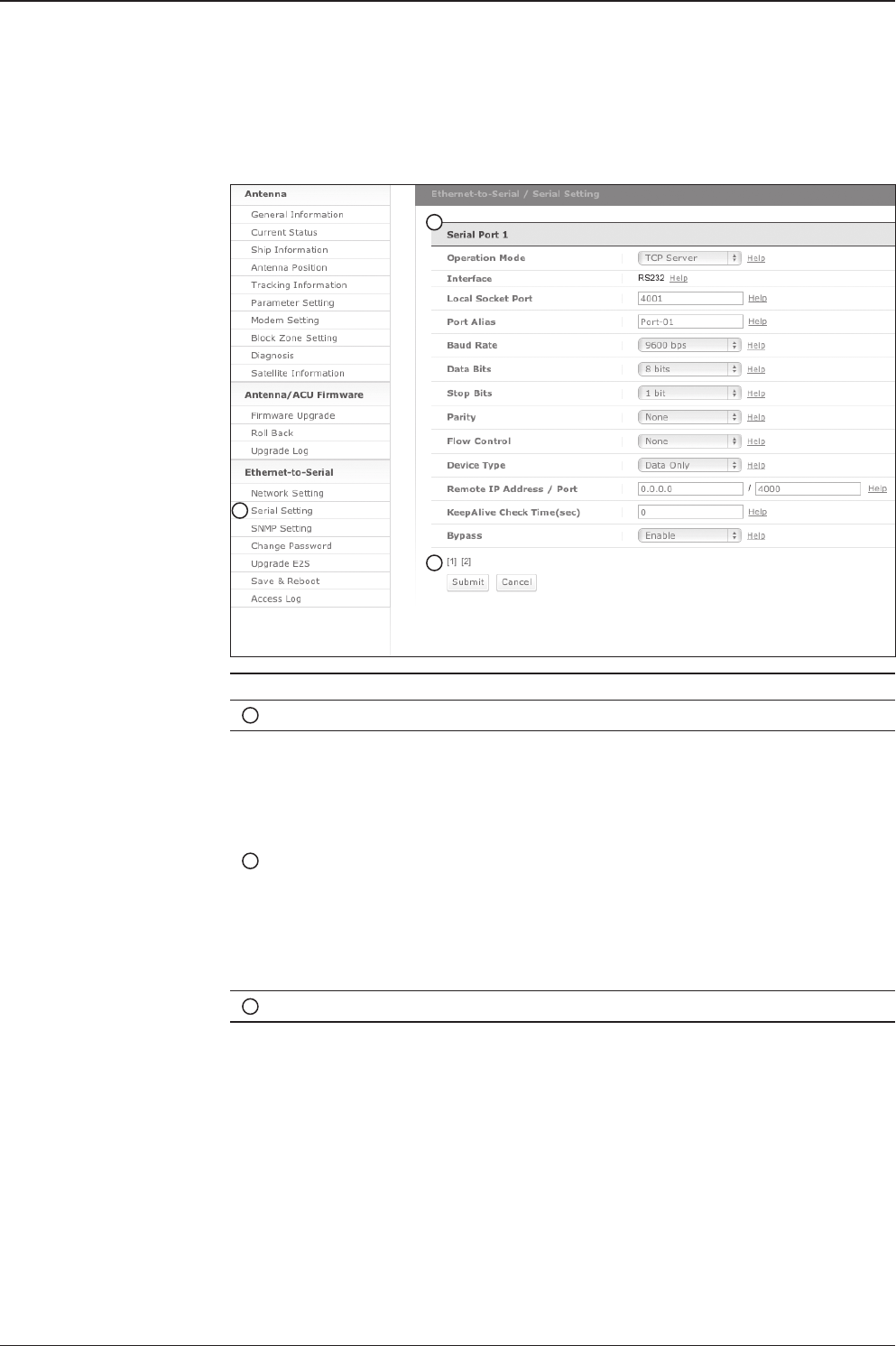
v130 – Marine Satellite Communication System
110
Serial Setting [1]
No. Item Description
1Serial Setting Congure Serial port [1] and Serial port [2]
2Serial Port [1]
Serial Port [1] is to communicate with an external modem via
Ethernet. Follow the instruction below to congure Serial port
[1] and press Submit button. Go to “Save & Reboot” page
and press Save & Reboot button to validate the changes.
- Operation mode: TCP Server
- Local socket port: 4001
- Baud Rate: 9600 bps
- Data Bit: 8 Bit
- Stop Bit: 1 Bit
- Parity: None
- Flow Control: None
The data communication between the modem and the PC
may disconnect while setting these parameters.
3[1][2] Select to congure Serial port [1] or Serial port [2]
1
2
3

111
REMOTE WEB ACCESS
Serial Setting [2]
Serial setting [2] page
No. Item Description
1Serial Setting Congure Serial port [1] and port [2]
2Serial Port [2]
Port [2] is to communicate with the PC Control via Ethernet.
Follow the instruction below to congure Serial port [2] and
press Submit button. Go to “Save & Reboot” page and press
Save & Reboot button to validate the changes.
- Operation mode: TCP Server
- Local socket port: 4002
- Baud Rate: 19200 bps
- Data Bit: 8 Bit
- Stop Bit: 1 Bit
- Parity: None
- Flow Control: None
The ACU control settings should be applied as same above.
3[1][2] Select to congure Serial port [1] or Serial port [2]
1
2
3
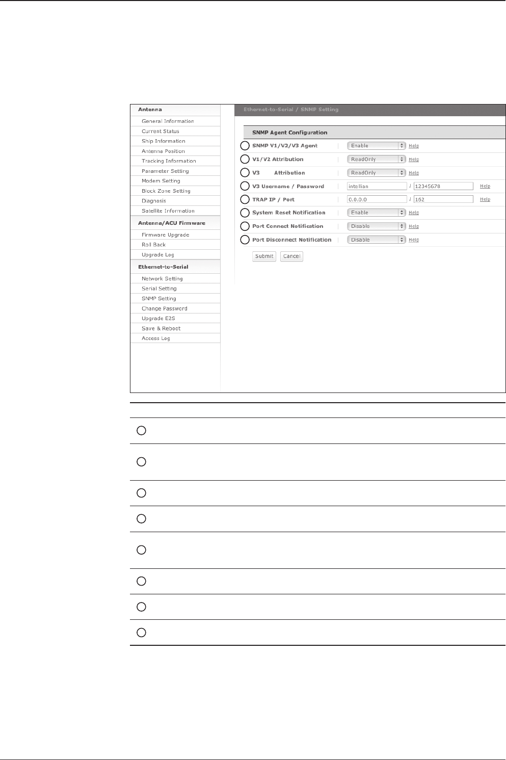
v130 – Marine Satellite Communication System
112
SNMP Setting
No. Item Description
1SNMP v1/v2/v3 Agent Enable or disable the SNMP (Simple Network
Management Protocol) agent.
2V1/2 Attribution
Congure the SNMP v1/v2 attributes (Read-Only, Read-
Write, Disable). The community name of SNMP v1/v2 is
“public”.
3V3 Attribution Congure the SNMP v3 attributes (Read-Only, Read-
Write).
4V3 Username /
Password
Set a v3 username & password of the SNMP agent.
5TRAP IP / Port
Set the trap IP address and socket number of the SNMP
trap server. Trap feature will be disabled if the trap IP is
set to 0.0.0.0.
6System Reset
Notication
Enable or disable the system reset SNMP trap
notication.
7Port Connect
Notication
Enable or disable the port connect SNMP trap
notication.
8Port Disconnect
Notication
Enable or disable the port disconnect SNMP trap
notication.
SNMP setting page
1
2
3
4
5
6
7
8
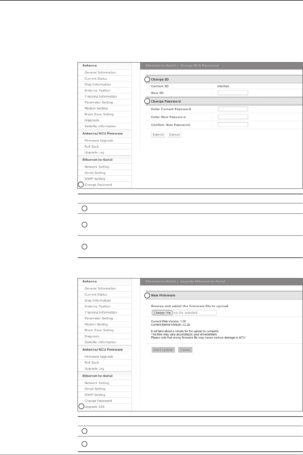
113
REMOTE WEB ACCESS
Change Password
No. Item Description
1Change Password Change your login ID (user name) and password.
2Change ID
Enter your current login ID (user name) and new login
ID. Press Submit button to validate the changes that are
made to the login ID
3Change Password
Enter your current login password and new login
password. Press Submit button to validate the changes
that are made to the login password.
Change password page
1
2
3
No. Item Description
1Upgrade E2S Upgrade the rmware of Ethernet-to-Serial module.
2New Firmware Select a new rmware le and press Start Update button to
upgrade the rmware of Ethernet-to-Serial module.
Upgrade E2S (Ethernet-to-Serial)
Upgrade E2S page
1
2
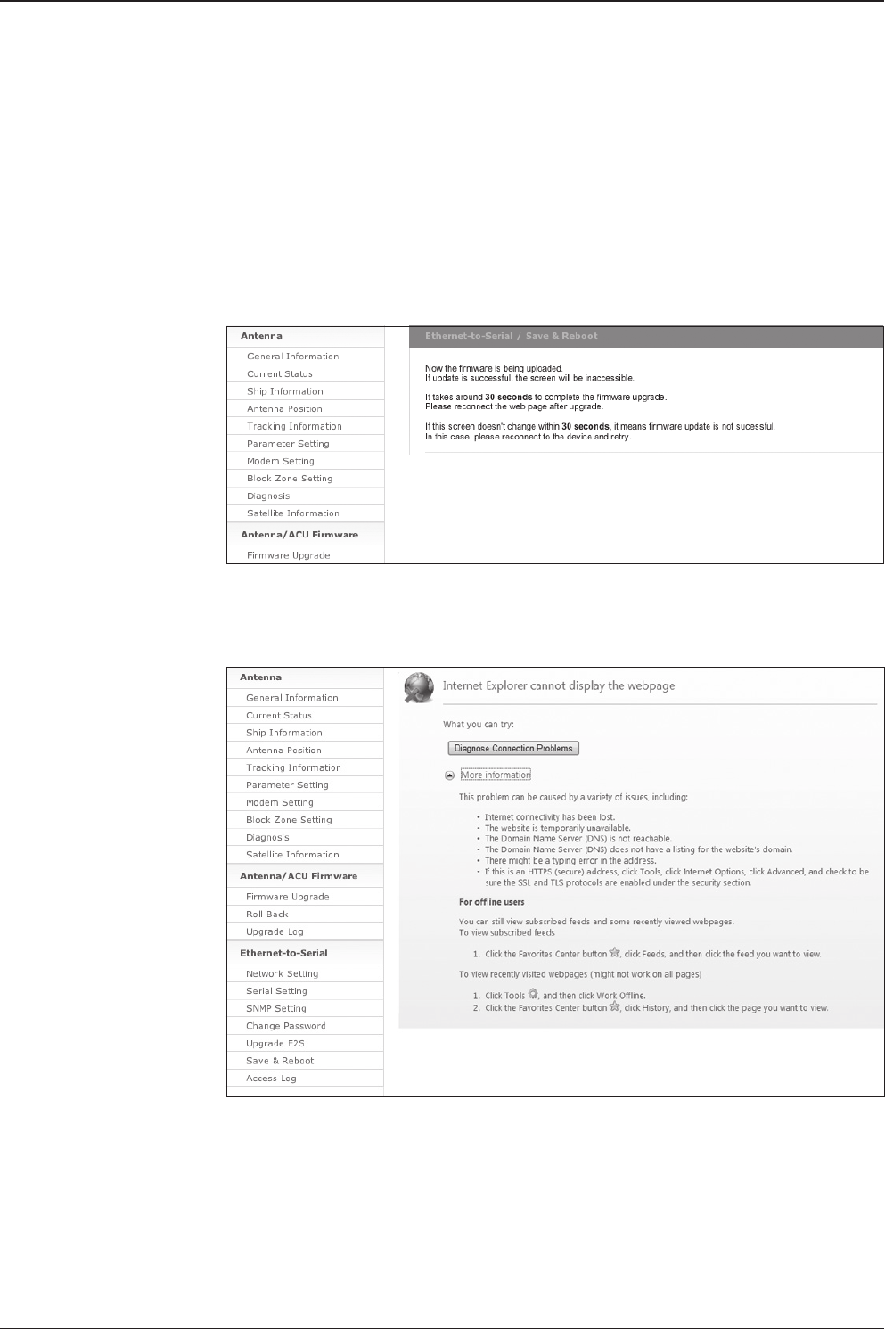
v130 – Marine Satellite Communication System
114
Upgrade Steps
1. Click on “Browse” button to select the E2S rmware le (.bin) that you wish to upgrade.
2. Click on “Start Update” button to update the E2S rmware. Wait until the page is loaded.
3. It’ll inform you that the rmware is being uploaded.
4. It takes around 30 seconds to complete the rmware upgrade. Please reconnect
the web page after upgrade.
Firmware
uploaded
message
System disconnection
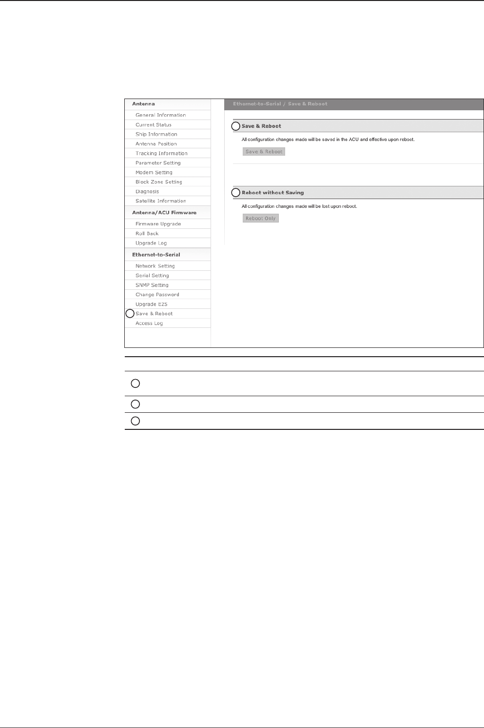
115
REMOTE WEB ACCESS
Save & Reboot
Save & reboot page
No. Item Description
1Save & Reboot Save settings to the ACU and reboot or reboot the
system without saving.
2Save & Reboot Save the modied settings and reboot the system.
3Reboot without Saving
Reboot the system without saving the modied settings.
1
2
3

v130 – Marine Satellite Communication System
116
Access Log
No. Item Description
1Access Log Display user’s log information (Date/Time, Login ID and IP)
Access log page
1

117
Technical Specication
Warranty
This product is warranted by Intellian Technologies Inc., to be free from defects in
materials and workmanship for a period of THREE (3) YEARS on parts and ONE
(1) YEAR on labor performed at Intellian Technologies, Inc. service center from the
purchased date of the product.
Intellian Technologies, Inc. warranty does not apply to product that has been
damaged and subjected to accident, abuse, mis-use, non-authorized modication,
incorrect and/ or non-authorized service, or to a product on which the serial number
has been altered, mutilated or removed.
It is required to present a copy of the purchase receipt issued by Intellian
Technologies,Inc. that indicates the date of purchase for after-sales service under
the warranty period. In case of failure to present the purchase receipt, the warranty
period will begin 30 days after the manufacturing production date of the product
purchased.
Any product which is proven to be defective in materials or workmanship, Intellian
Technologies, Inc. will (at its sole option) repair or replace during the warranty period
in accordance with this warranty. All products returned to Intellian Technologies, Inc.
under the warranty period must be accompanied by a return material authorization
(RMA) number issued by the dealer/distributor from Intellian Technologies,Inc. and
a copy of the purchase receipt as a proof of purchased date, prior to shipment.
Alternatively, you may bring the product to an authorized Intellian Technologies, Inc.
dealer/distributor for repair.

v130 – Marine Satellite Communication System
118
Technical Specication
v110 v130
Approvals
CE – conforms to EU Directive 89/336/EEC
FCC – veried to CFR47: Part 15
Dimensions
Satellite Antenna Unit 147.4 x 152.2 cm
(58” x 59.9”)
165.2 x 168.9 cm
(65” x 66.5”)
Antenna Dish Diameter 105 cm (41.3”) 125 cm (49.2”)
Antenna Control Unit 43.1 x 38.1 x 4.4 cm (17” x 15” x 1.7”)
Weight
Satellite Antenna Unit 139.5 kg (307.5 lbs) 149.7 kg (337 lbs)
Antenna Control Unit 5.2 kg (11.5 lbs)
Antenna System Performance
TX Frequency 14.0 ~ 14.5 GHz Ku-band
TX Gain 41.7 dBi 43.2 dBi
RX Frequency 10.95 ~ 12.75 GHz Ku-band
RX Gain 39.8 dBi 42.1 dBi
Polarized Feed Cross-pol or Co-pol
LNB pol Control Automatic LNB pol-angle Control
Azimuth Range Unlimited
Elevation Range -15° ~ +120° -20° ~ +120°
Cross-level Range ± 37°
Stabilization Accuracy 0.2° peak mis-pointing @ max ship motion condition
Max Ship’s Motion ±25° roll, ±15° pitch, ±8° yaw @ 6 sec
Turning Rate Up to 12°/ sec & 5°/ sec2
BUC 4W, 8W (optional)
Rack Mount Antenna Control Unit
Display 2 Line 40 Character Graphic VFD Module
Serial Interface RS232C (19200 bps 8, N, 1)
Modem Interface Ethernet port / RS232C / I/O ports
Remote Access TCP / IP
Input Power 100~240 V AC, 50~60 Hz
(Max 350W including 8W BUC Power)
Gyrocompass Interface NMEA / Synchro

119
www.intelliantech.com
info@intelliantech.com
APAC
Headquarters
Intellian Technologies, Inc.
348-5 Chungho-Ri, Jinwi-Myeon
Pyeongtaek-Si, Gyunggi-Do 451-862 Korea
T +82 31 379 1000 F +82 31 377 6185
Seoul Ofce
Intellian Technologies, Inc.
2F Dongik Building, 98 Nonhyun-Dong
Gangnam-Gu, Seoul 135-010 Korea
T +82 2 511 2244 F +82 2 511 2235
Maritime Technical Center
Busan Ofce
Intellian Technologies, Inc.
#1701,60, Centum buk-daero,
Haeundae-gu, Busan 612-050 Korea
T +82 51 746 9695 F +82 51 746 9440
Americas
Irvine Ofce
Intellian Technologies USA, Inc.
9004 Research Drive
Irvine, CA 92618 USA
T 949 727 4498 F 949 271 4183
EMEA
Rotterdam Ofce
Intellian B.V.
Bristolstraat 1, 3047AB
Rotterdam, The Netherlands
T +31 1 0820 8655 F +31 1 0820 8656
Tech Support: SupportAPAC@intelliantech.com
Tech Support: SupportAMERICAS@intelliantech.com
Tech Support: SupportEMEA@intelliantech.com
Southampton Ofce
Intellian Ltd.
Epsilon House, Enterprise Road, Southampton Science Park,
Southampton, Hampshire SO16 7NS, United Kingdom
T +44 2380 019 021 F +44 2380 767 092
