V240C Manual
2017-12-08
: Intellian V240C Manual v240C_Manual v240 d
Open the PDF directly: View PDF ![]() .
.
Page Count: 177 [warning: Documents this large are best viewed by clicking the View PDF Link!]

Marine Satellite Communication Antenna System
v240C
Installation and Operation Manual


Serial number of the product
This serial number will be required for the all troubleshooting or service inquiries.
© 2017 Intellian Technologies, Inc. All rights reserved. Intellian and the Intellian
logo are trademarks of Intellian Technologies, Inc., registered in the U.S. and other
countries. The v-Series and the v240C are trademarks of Intellian Technologies,
Inc. Intellian may have patents, patent applications, trademarks, copyrights,
or other intellectual property rights covering subject matter in this document.
Except as expressly provided in any written license agreement from Intellian,
the furnishing of this document does not give you any license to these patents,
trademarks, copyrights, or other intellectual property.
All other logos, trademarks, and registered trademarks are the property of their
respective owners. Information in this document is subject to change without
notice.
Every effort has been made to ensure that the information in this manual is
accurate. Intellian is not responsible for printing or clerical errors.
Doc. No. UM-R0-170323-V2.7
3572-13-8560
(01)
intellian v240c

INDEX

5
INDEX
INTRODUCTION 7
Introduction to Intellian v240C 8
Features of Intellian v240C 9
Basic System Congurations 10
INSTALLATION 11
System Components 12
Planning the Installation 18
Antenna Installation 21
INSTALLING THE ACU 55
Mounting the ACU 56
Ship Gyro Connection 58
Wi-Fi and Bluetooth Connection 60
ACU Connector Guide 63
OPERATING THE ACU 65
Introduction 66
Normal Menu 67
Setup Menu 71
Installation Settings 72
Antenna Settings 74
Satellite Settings 86
System Settings 93
Aptus®101
Introduction to Aptus®102
Software Installation 103
PC to ACU Communication Setup 104
Toolbar Menus 107
System Property Status Dashboard 114
Work View Tabs 118
Aptus® WEB 135
Introduction 136
Main Page 137
Antenna Settings 141
Firmware & Conguration 149
Administration 155
APPENDIX A: Java Download and Install Guide 164
APPENDIX B: Setup Bluetooth Connection 168
TECHNICAL SPECIFICATION 175
WARRANTY 177

v240C – Marine Satellite Communication System
6

7
INTRODUCTION
Introduction to Intellian v240C
Features of Intellian v240C
Basic System Congurations
INTRODUCTION

v240C – Marine Satellite Communication System
8
Introduction to Intellian v240C
The Intellian v240C is a 2.4 meter C-band marine VSAT communication antenna
system. With its 3-axis stabilized platform and enhanced vibration and shock
damping design, the v240C can perform extremely well on all types of ships that
require “always on” and “high speed” broadband communications no matter how
rough the weather and sea conditions are.
The v240C requires minimal involvement to commission . It is easy to operate and
also simple to upgrade and manage. Each unit comes preloaded with a ready-
to-use, client-customized library that can be conveniently tailored further via PC
software (also included with the unit), and rmware updates can be done entirely
through the Wi-Fi ACU. Wi-Fi router enables easy connection and control of ACU,
allowing operators to check the status of the VSAT.
The all new Antenna Control Unit (ACU) supports Wi-Fi connectivity for a simple
remote PC connection. If the ACU is installed at a great distance from the antenna,
then the built-in Bluetooth connection module can enable a PC connection right
alongside the dome.
Robust and versatile, the v240C marks an new era for VSAT connectivity on the
open water for deep sea vessels that require global coverage.

9
INTRODUCTION
Features of Intellian v240C
Automatic Polarization Switching
Intellian v240C antenna automatically changes between linear and circular
polarization while it does not require manual or physical change. When a polarization
is selected from ACU or PC Control Program, the Feed Horn is automatically
adjusted accordingly, which is patented technology developed by Intellian.
DVB/DVB-S2 and NBD detection capability
Intellian v240C is capable of detecting DVB-S/DVB-S2 signal, SCPC, and Narrow-
Band signal. Thanks to its integrated digital tuner and the narrow band detector
(NBD).
Wireless communication with the ACU
The ACU of the Intellian v240C offers upgraded functions. The built-in Wi-Fi
wireless network card enables the ACU to be wirelessly connected, and it can be
either turned on and off by a switch. After connecting with Wi-Fi wireless network
or setting up a network with ACU, it will be easy to monitor, control, and change the
settings of Intellian antenna system wirelessly using laptops, smartphones, or any
kind of wireless devices.
Antenna log data and rmware upgrade through USB
The ACU of v240C now automatically stores all action data of Intellian antennas
onto a built-in memory, and all existing logs are available to be transferred onto
USB drivers. Also just by plugging in the USB with rmware update les stored, the
rmware can be automatically updated and upgraded onto the ACU.
Bluetooth module support
When the Intellian supplied Bluetooth module is equipped on a main control unit of
Intellian antenna, users can access and control the antenna with a laptop that has
Bluetooth capability. This will lead to easier and more effective ways to setup and
maintain the system.
Maximized RF performance
The main reector, Feed-horn and other RF parts are newly designed to maximize
the antenna performance for maritime application. Not only the gain and Maximum
Allowed EIRP Density are the highest level amongst the similar-sized VSAT antenna,
Intellian v240C conforms to various ESV (Earth-Station-on Vessels) standards and
FCC requirements.
v240C – Marine Satellite Communication System
10
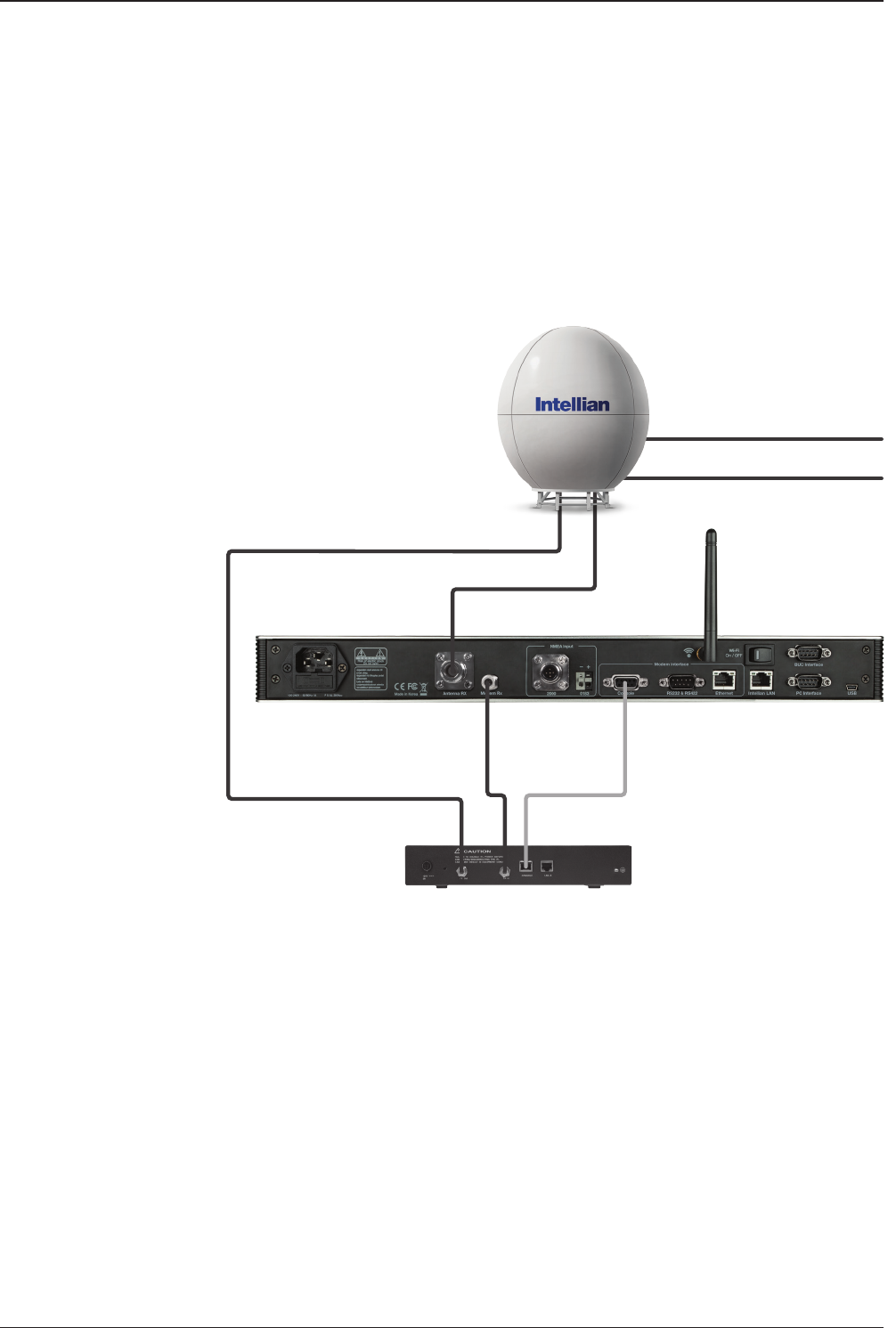
Basic System Congurations
For your satellite VSAT system to work properly, the system will have to be connected
with all of the provided components properly as shown in the gure below (Refer to
next chapter ‘Installation’ in this manual for more detailed connection instructions).
Basic System
Configuration
Air Conditioner Power
220V AC
90~260V AC
Antenna
Control Unit
Modem InterfaceModem RX
Modem TX
Antenna RX
Satellite
Modem
*Modem is not supplied

11
INTRODUCTION
INSTALLATION
System Components
Antenna Unit
ACU (Antenna Control Unit)
Installation Kit
Planning the Installation
Selection of Antenna Installation Site
Congure Radiation Hazard/Blockage Zones
System Cables
Power Requirement
Tools Required for Installation
Antenna Installation
Unpacking the Wooden Crate
Antenna Dimensions
Antenna Mounting Templates
Position the Radome
Open the Radome Hatch
Mount the Radome
RF Cable Connections
Secure the RF Cables

v240C – Marine Satellite Communication System
12
System Components
Antenna unit
Antenna Unit
The antenna of Intellian v240C is composed with the following components for the
optimum search and reception of satellite signal.
• Mechanical Unit – manipulates the antenna to receive the optimal satellite signal
regardless of the movement of the vessel.
• Control Unit – controls mechanical operation of the antenna.
• RF Unit – transmits the optimum satellite signal to the receiver.
• Radome – protects the antenna from the severe marine environment.

13
INSTALLING THE ANTENNA
ACU (Antenna Control Unit)
The Antenna Control Unit (ACU) provides the power to the antenna and
controls the various settings of the antenna.
Antenna Control Unit
The functions of the ACU are as follows:
• Monitor the antenna status
• Change the target satellite
• Set up the user environment
• Set the current GPS information
• Set satellite information
• Move antenna manually
• Built-in real-time diagnostics function and event log recorder
• Set up the interface with a PC
• Supports Wi-Fi operation
• Log data and rmware upgrade through USB
• Built-in web-based remote control management

v240C – Marine Satellite Communication System
14
Installation Kit
Contains the items required for securing the antenna unit and ACU to the vessel.
ACU box components
Description Q'ty Size Remarks
Antenna Control Unit (ACU) 1 43.1 x 38 x 4.4cm Antenna Control Unit
Wi-Fi Antenna 1
ACU Side Bracket (Rack) 2 ACU to 19inch Rack
ACU Side Bracket (Table) 2 ACU to Table
USB Cable (A-A) 1 1.8m ACU to PC
D-Sub 9 pin Male Connector 2 ACU
N to F Adaptor 1 N(Male) to F(Female) Adaptor
USB Flash Drive 1
User Manual 1
RF Hazard Sticker 1 Radiation Safety Distance Label
Self-Tapping Screw 5 M4 x 16L
Bolt Kit for Table Mount Bracket
Sems Bolt 5 M3 x 12L
Flat Head Screw 10 M4 x 12L Bolt Kit for Rack Mount Bracket
Cable kit components
Description Q'ty Size Remarks
RG6 Cable 1 3m ACU to Modem
AC Power Cable 1 1.5m ACU Power (220V)
AC Power Cable (110V Plug) 1 1.5m ACU Power (110V)
PC Serial Cable 1 1.8m ACU to PC
iDirect Interface Cable 1 1.5m ACU to Modem
Modem Cable Pin Connection
Manual 1

15
INSTALLING THE ANTENNA
Bolt Kit for Installation Box
Description Q'ty Size Remarks
Hex Bolt 4 M16x40L
Bolt Kit for Stable MountFlat Washer 4 M16
Spring Washer 4 M16
Hex Bolt (BUMAX) 9 M12x60L
Bolt Kit for PostLock Washer 17 M12
Nut (BUMAX) 9 M12
Hex Bolt 235 M6x35L Bolt for Radome Assembly
Hex Bolt 55 M6x35L Bolt for Radome Base Assembly
Flat Washer 580 M6(Ø18) Washer & Nut for Radome &
Radome Base Assembly
Spring Washer 290 M6
Hex Bolt 10 M6x35L
Bolt Kit for Upper Radome Lift
Bracket
Flat Washer 20 M6(Ø18)
Spring Washer 10 M6
Hex Bolt (BUMAX) 9 M12x60L
Bolt Kit for Antenna MountingLock Washer 17 M12
Nut (BUMAX) 9 M12
Stable Mount Jig 1
Silicon 4
Silicon Gun 1
Loctite 263 1
v240C – Marine Satellite Communication System
16
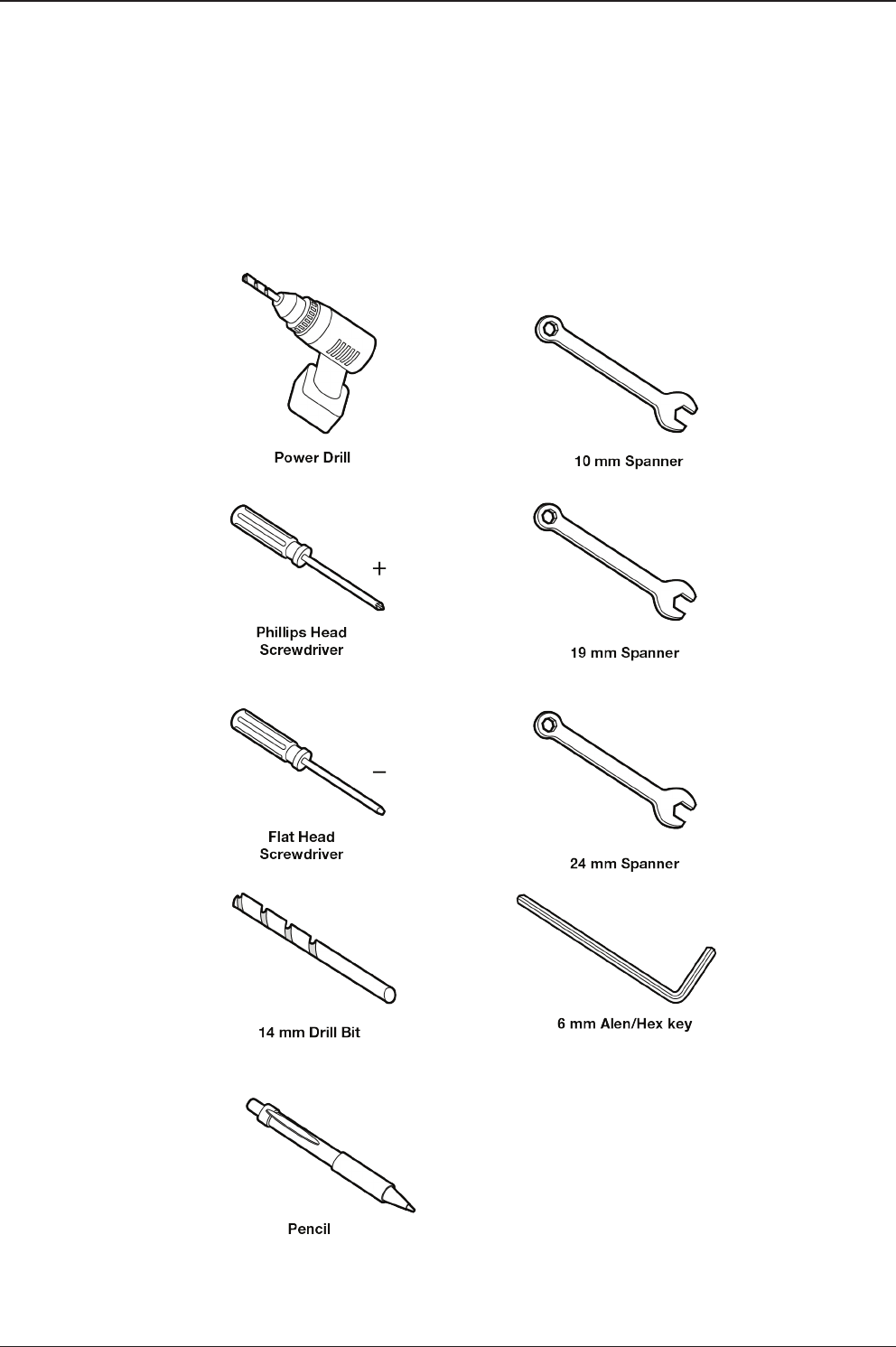
Tools required for Installation

17
INSTALLING THE ANTENNA
Box Adaptor
Sillicon Gun
Sillicon
10/19/24mm Box Socket
Monkey Wrench
Long Socket
Ratchet Handle
Impact Drill

v240C – Marine Satellite Communication System
18
Planning the Installation
Selection of Antenna Installation Site
The installation of v240C requires extreme precaution and safety measures given its
size and weight. Failure to follow the correct installation process may lead to injury
to the installer and/or cause damage to the system.
In order to maximize the performance of the system, a thorough review of this
installation guide is strongly recommended, as well as executing the installation
process as it is noted on this manual.
The system should be placed where there would be no blockage that would interfere
the signals. A safe mounting place should be selected for given its heavy weight
and size.
• System Cables
Before installing the system cables, you need to take the following points
into consideration.
1. All cables need to be well clamped and protected from physical damage and
exposure to heat and humidity.
2. Remember to observe the minimum bend radius of the selected cable.
3. Where a cable passes through an exposed bulkhead or deck-head, a watertight
gland or swan neck tube should be used.
• Power Requirements
You need to follow the power requirements to avoid damage the system.
Intellian v240C is designed to work on a power supply between 90-260V AC.
• Extending the Cables
The cables that have been supplied with your Intellian system should be of adequate
length to complete the installation on most boats.
• Power Cable
This cable supplied at a length of 10m.
• RF Cable
This cable is supplied at a length of 30m as an optional item. If a longer length
is required you should replace this cable with an extended RF cable supplied by
Intellian Technologies.
NOTE:
Exceeding the indicted cable lengths will result in reduced performance of
your system.

19
INSTALLING THE ANTENNA
Installation and mounting of antenna
The method of installation and mounting of antenna may vary with vessel design but
the following procedures are applicable in most situations, and will result in a secure
and effective installation.
Conrmation of size prior to installation
• Conrm the height and diameter of the bottom surface of the antenna before
installing it.
• The space must be sufcient for installing the antenna unit considering the height
and diameter of the antenna.
• The height and the diameter of the bottom surface of the antenna are as shown
in the following drawing. It is strongly suggested that the installation is conducted
using a crane.
Antenna
Dimensions
v240C – Marine Satellite Communication System
20
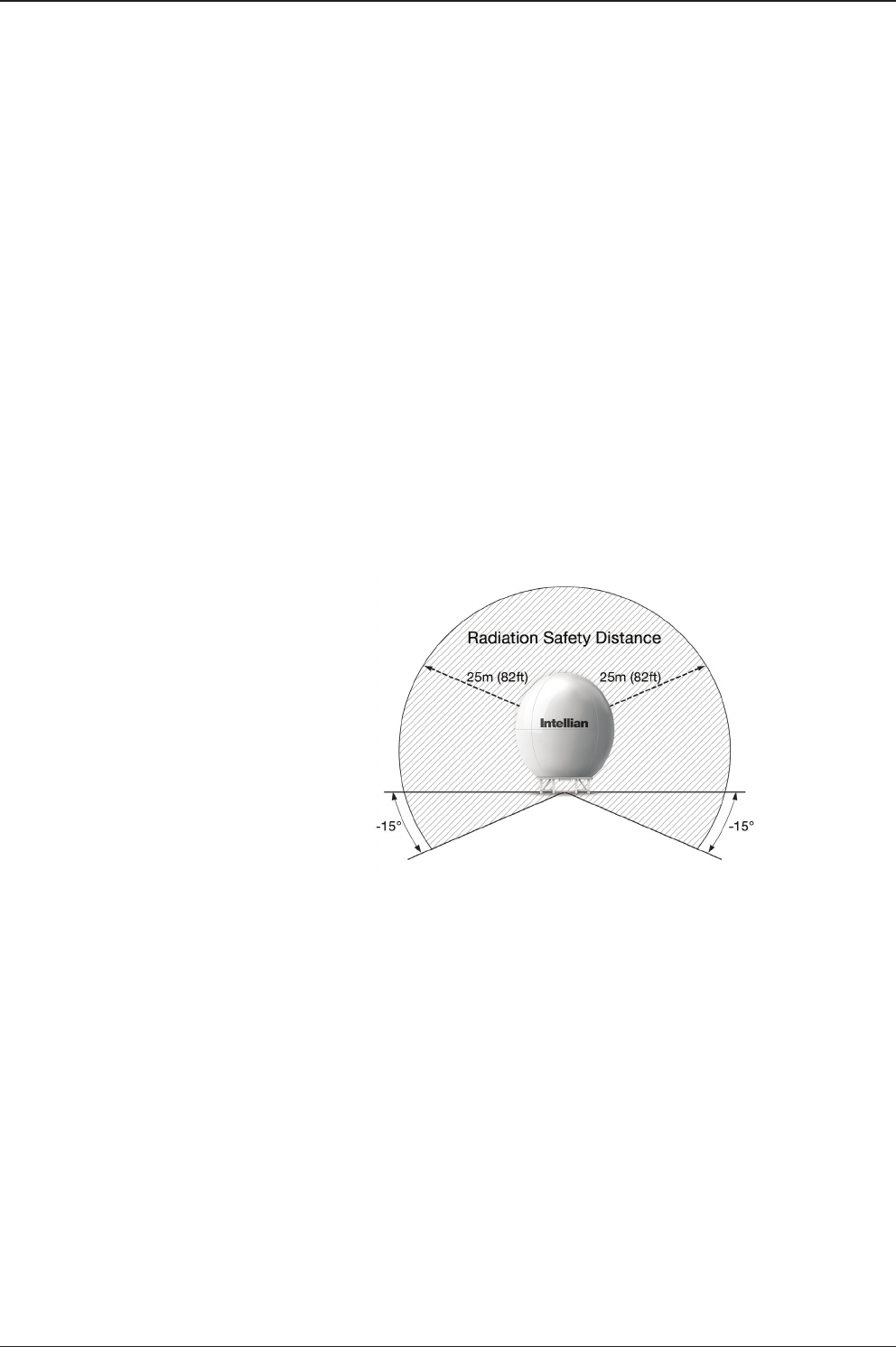
RF Hazard Precautions
The antenna is designed to be used with radiation transmit equipment manufactured
by others. Exposure to RF radiation, including exposure associated with an improper
use of the transmit equipment, may be hazardous to persons close to the above
deck unit. Ensure safety of personnel who work on the system.
During transmission, ensure to keep the minimum safety distance. The recommended
minimum safety distance to the reector on the focal line is about 25m, based on a
radiation level of 5mW/ cm2 that applies under occupational/controlled environment.
No hazard exists >15° below the antenna’s mounting plane.
Safe access from radiation hazard
21
INSTALLING THE ANTENNA
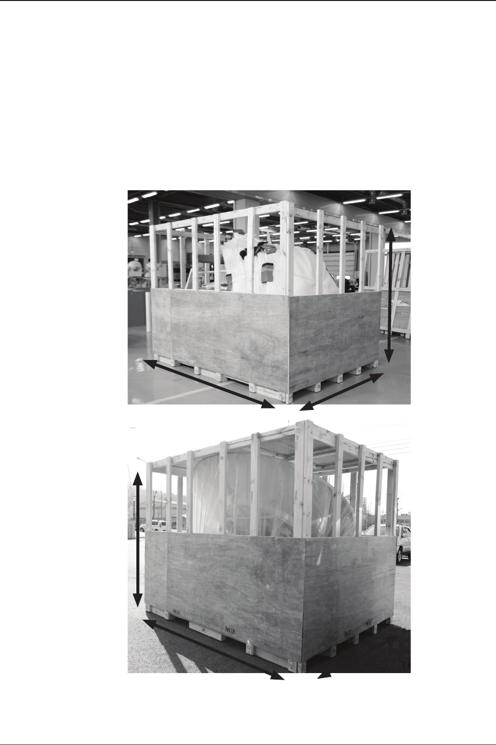
Antenna Installation
Dismantling the antenna packaging (Packing is subject to change)
Upon the arrival of the antenna package, the following instruction needs to be
followed in order to execute the proper removal of the system from its original
packaging.
To secure the safe installation process, please make sure to have enough space
(10m x 10m x 10m) around the unit
A: 2300mm, B:2220mm, C:2700mm, D:3000mm, E:2220mm, F: 2300mm
1. Secure enough space for un-packaging procedures
A
D
EF
B
C

v240C – Marine Satellite Communication System
22
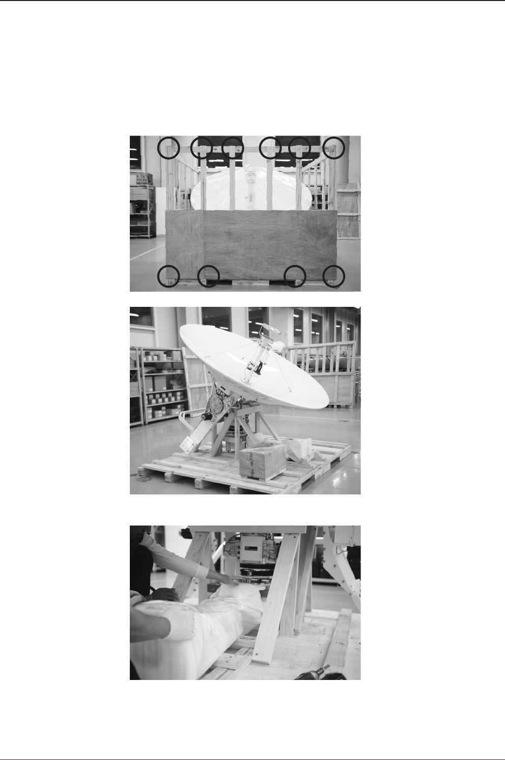
2. Dismantling the Radome Package
On the picture shown
on left, boxed-side of
wooden assembly needs
to be dismantled.
There are nails on the
circled parts of the
packaging.
The packaing will be
taken apart using an
Impact Drill.
The packaing will be
taken apart using an
Impact Drill.
A.
B.
C.

23
INSTALLING THE ANTENNA
Remove the wall as
shown left.
D.

v240C – Marine Satellite Communication System
24
3. Dismantling The Radome panels
Cut all the ties around the
radome panels.
Carefully remove the
radome panels.
After complete removal
of radome panels,
packaging should be as
shown right.
A.
B.
c.

25
INSTALLING THE ANTENNA
After complete removal
of the wooden bar in
section A directly above,
the packaging should be
seen as shown left.
Now prepare to remove
the Base frame by
removing bolts from
wooden crate oor and
base frame legs.
B.
C.
4. Removal of Radome Panel Supports and Base Frame
Remove the wooden bar
that supported radome
panels using an Impact
Drill.
A.

v240C – Marine Satellite Communication System
26
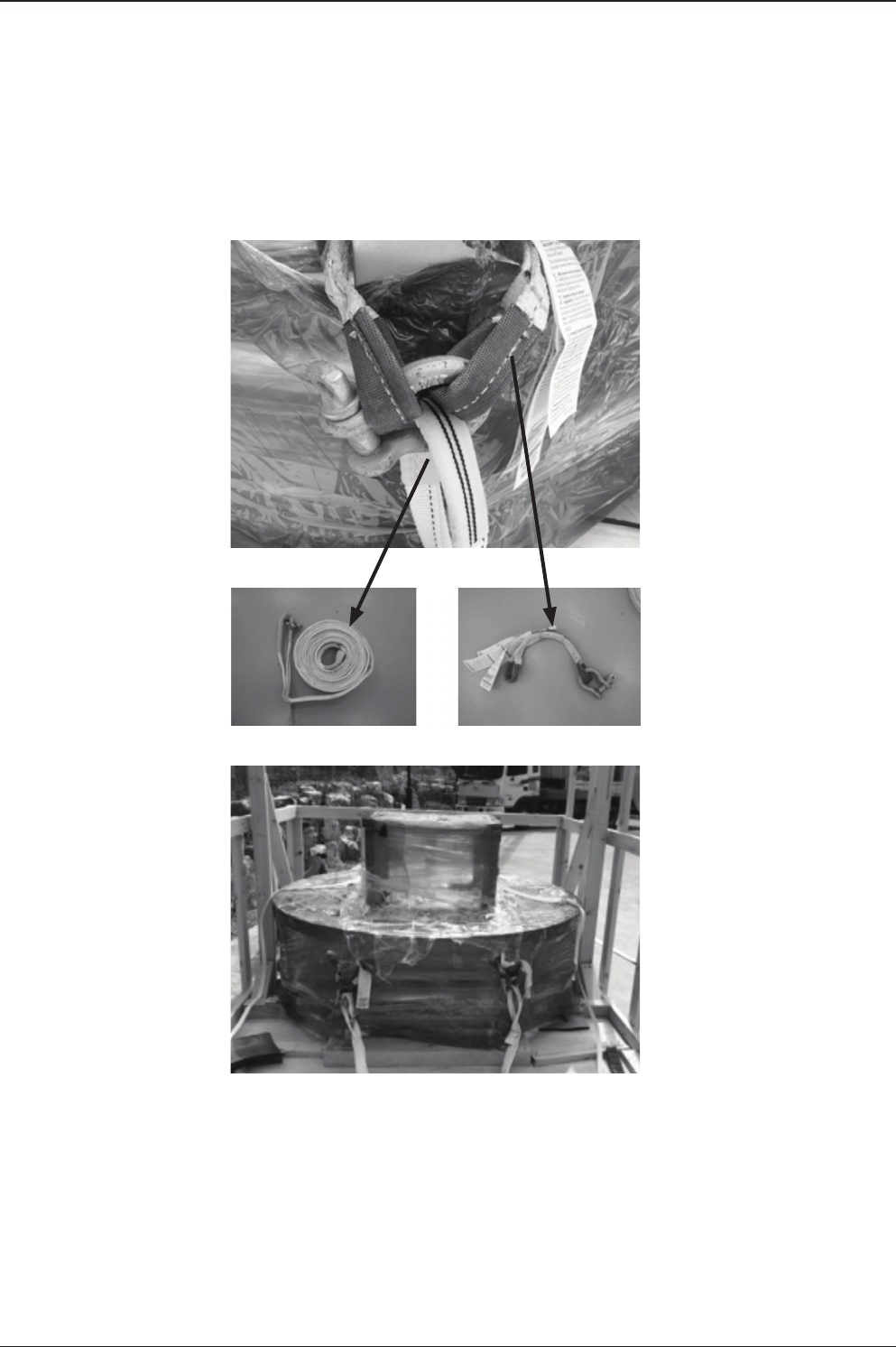
5. Attach buckles to the Base Frame
Now prepare to attach
buckles to base frame
in order to lift the base
frame from wooden crate.
As shown left, all buckle
ropes should be applied
to all 4 joints of base
frame.
After applying buckle
ropes to all 4 corners,
attach lifting strap to
buckle ropes.
A.
B.
C.
27
INSTALLING THE ANTENNA
Attachment of buckle
ropes and lifting ropes
should look as shown left.
A = 4000mm Lifting strap,
B = Buckle Rope
Base Frame ready to be
lifted up should be seen
as shown left.
D.
E.
F.
A B
v240C – Marine Satellite Communication System
28
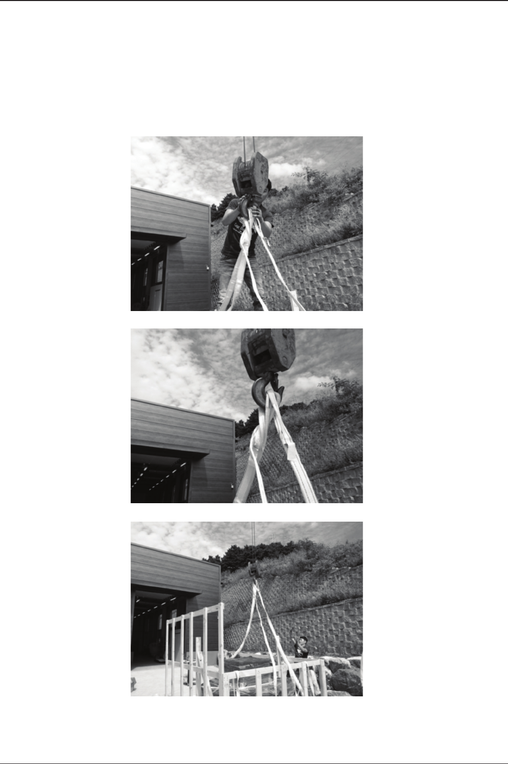
6. Dismantle Radome Base Frame
Now prepare to attach
buckles to base frame
in order to lift the base
frame from wooden crate.
Secure the strap tightly
as shown left for a safe
removal.
Make sure that the center
of Base Frame is located
right below of hook of
Crane to create a good
center of gravity and
perform safe removal of
base frame.
A.
B.
C.

29
INSTALLING THE ANTENNA
Very slowly lift up the
base frame and watch as
the base frame lifts up to
prevent big interference
with wooden crate.
Lower the base frame
onto the oor and remove
the lifting assembly.
D.
E.
v240C – Marine Satellite Communication System
30
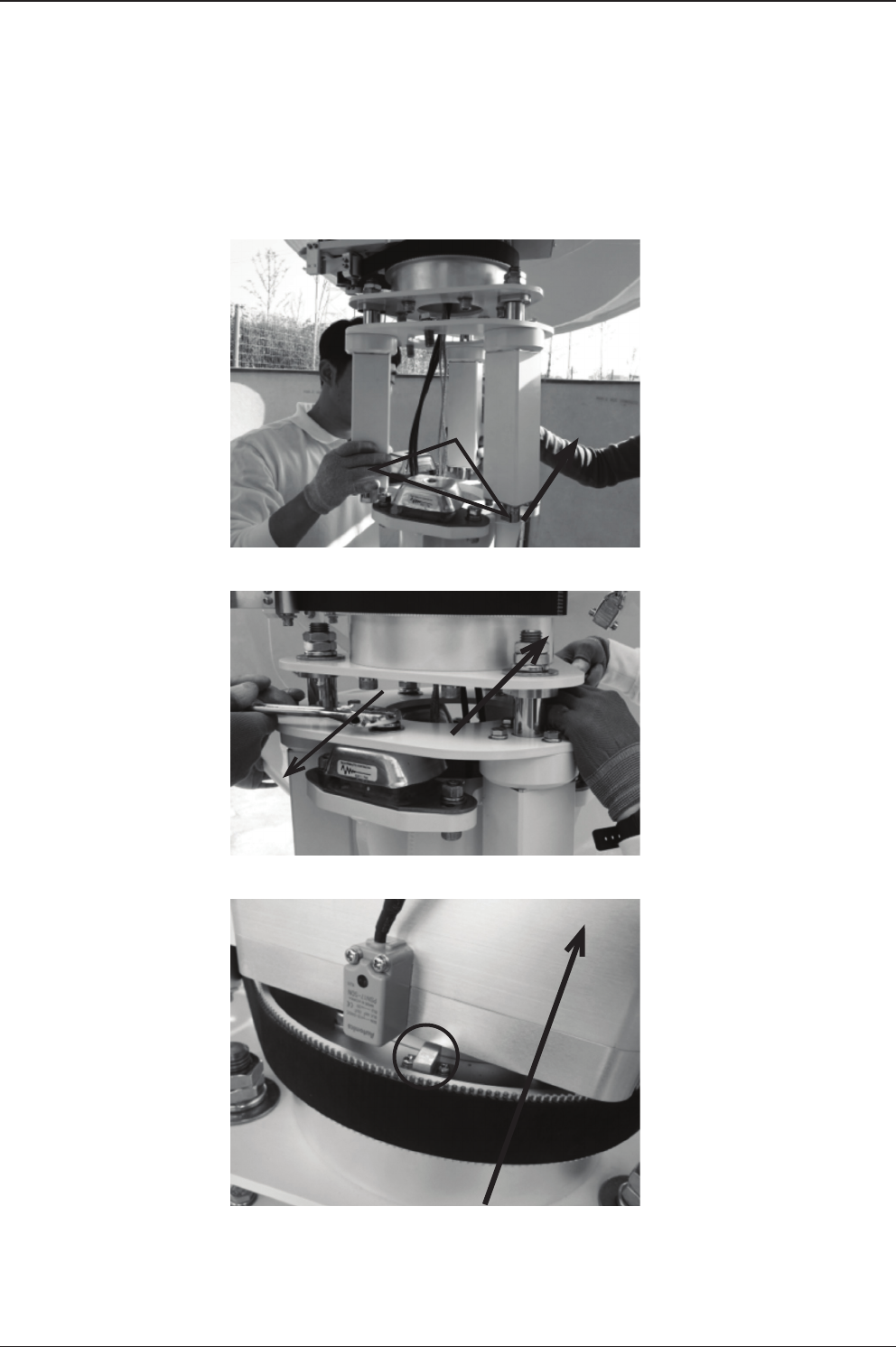
7. Dismantle the Antenna Package and Free the CL Arm
Dismantle the wooden
assembly of the antenna
package using an impact
drill.
Remove the vinyl layer
from the antenna.
Under the wooden
support, there is a post
laying. Remove the post
by sliding it out, then cut
the ties or tapes around
the post.
A.
B.
C.
31
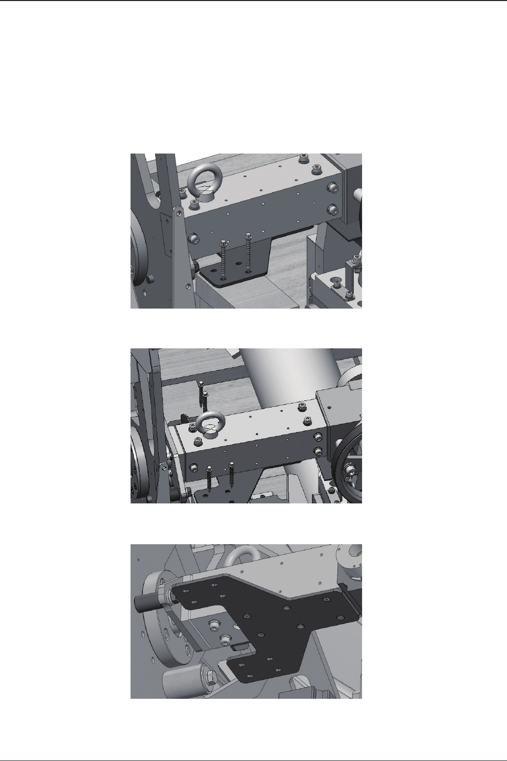
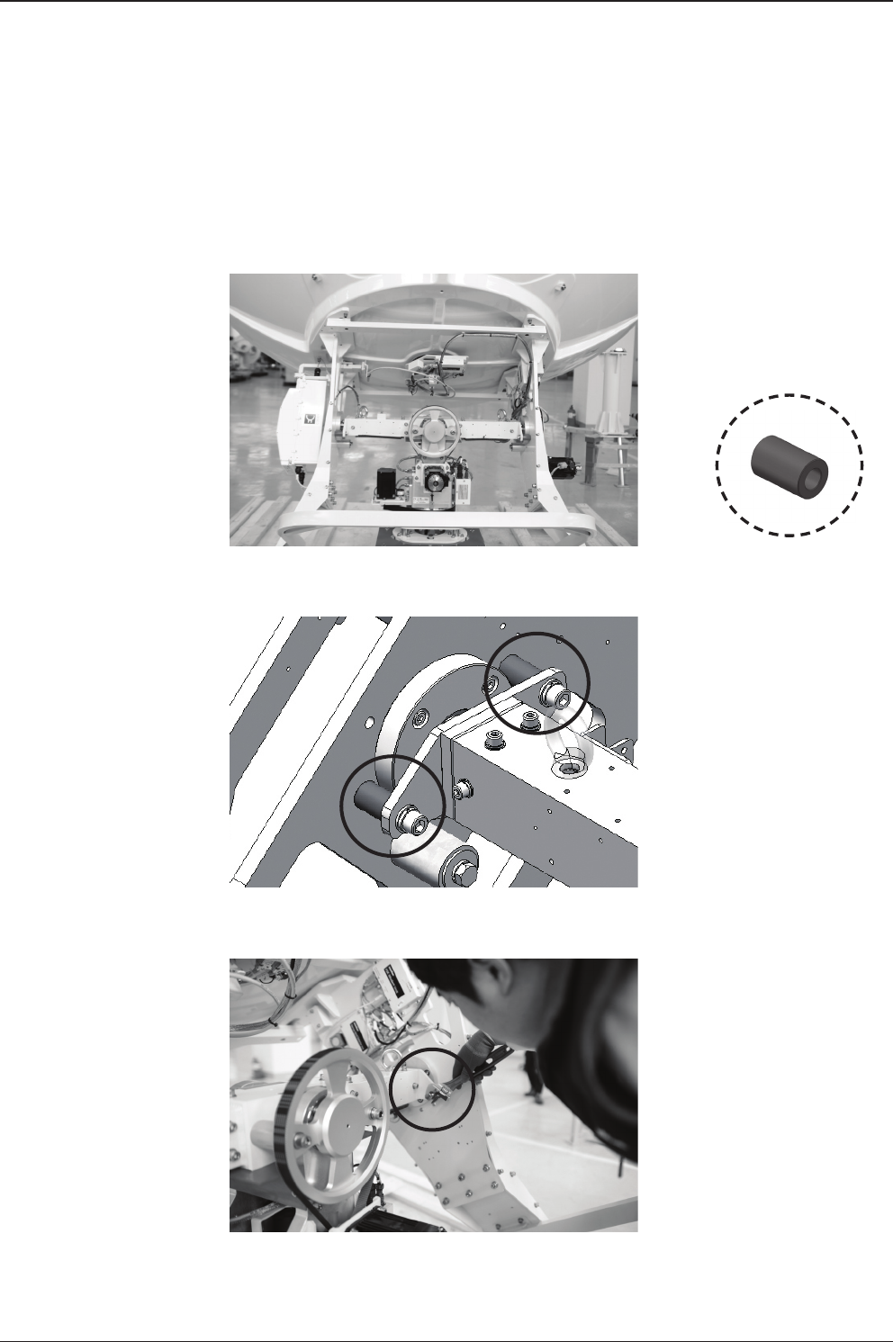
INSTALLING THE ANTENNA
Take out all brackets on
the rear of the CL ARM
by removing M5 at
head bolt (8EA) using an
impact drill.
F.
Locate the 2 brackets on
the rear of the CL Arm.
D.
Take out 8mm pieces
(8EA) securing the
brackets to the wooden
support bar.
E.
v240C – Marine Satellite Communication System
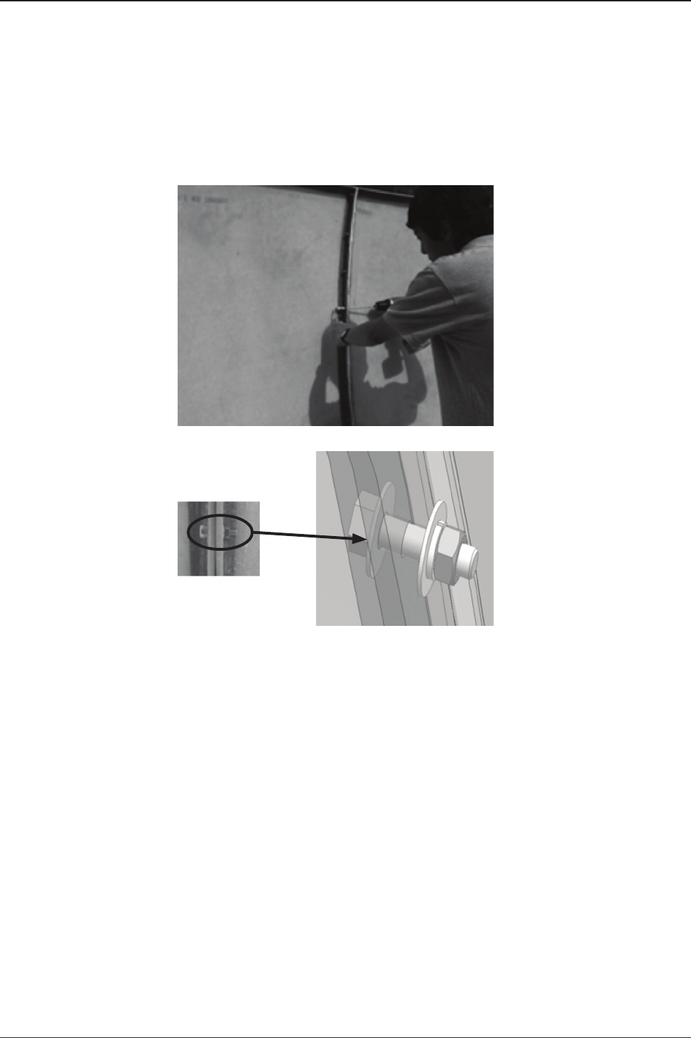
32
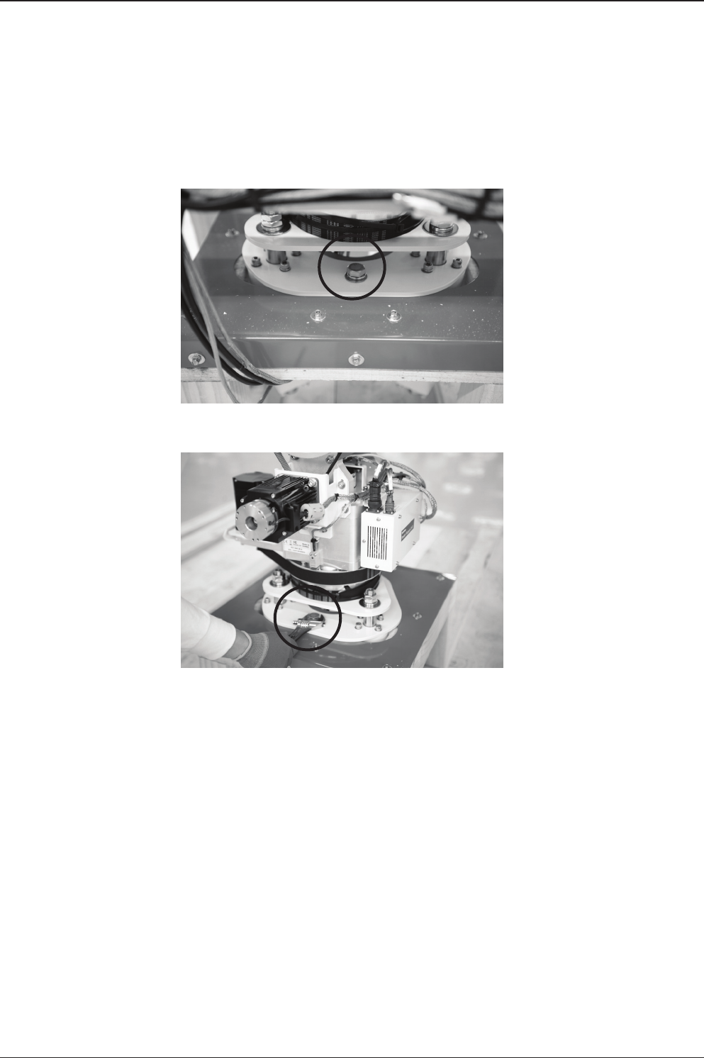
Locate the M12 Hex Bolts
(4EA) on both sides of the
EL Arm.
Remove the total 4 M12
Hex Bolts securing each
side of the EL Arm.
A.
B.
8. Remove Bolts on EL Arm
33
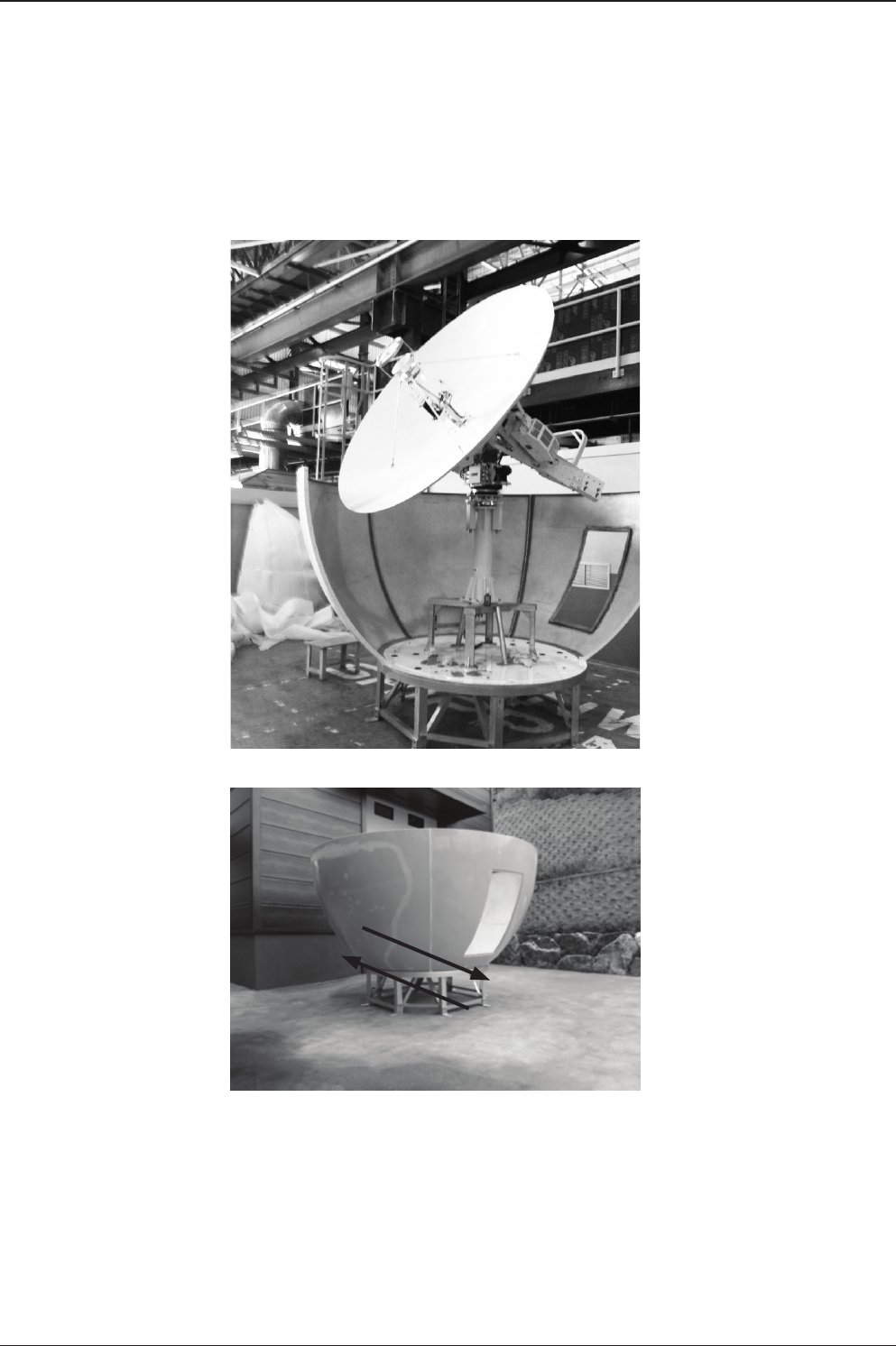
INSTALLING THE ANTENNA
Locate the M16 bolts
that secure the pedestal
assembly to the crate.
Remove the M16 Hex
Bolts and Nuts using a
wrench as shown left.
A.
B.
9. Free the Upper Antenna

v240C – Marine Satellite Communication System
34
10. Assembly of Base Frame and Post
With the direction of the
bow in mind, place the
post on the top of the
base frame.
Check to conrm
the orientation of the
pedestal support with
regards to the bow.

35
INSTALLING THE ANTENNA
Secure the lower pedestal
to the base frame with
the 8 M12 x 60 bolts
supplied. Lock the bolts
by installing double nuts
onto the bolts. Make
sure to apply Loctite 262
to the bolts to securely
tighten the assembly.
Now for the nal time,
please make sure that
the post is attached in
accordance with correct
bow direction. Power
switch unit mount plate
should be on the right
side when looking from
stern to bow of the base
assembly.
D.
E.
Please note the bow
direction as shown left.
C.
BOW Direction
Power Switch Unit
Mount Plate
v240C – Marine Satellite Communication System
36
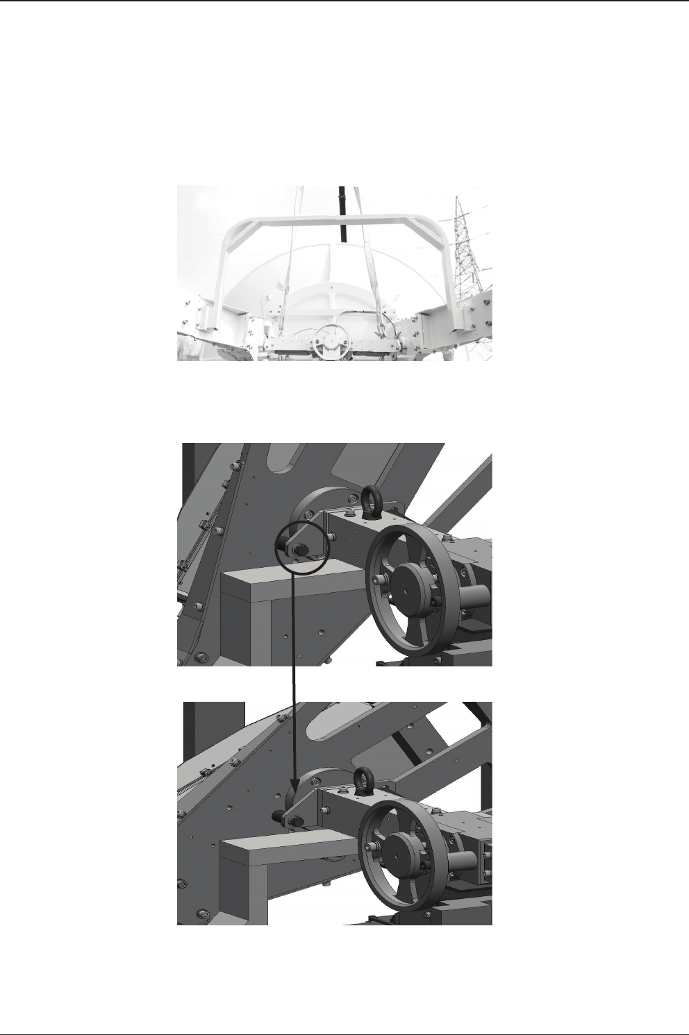
11. Detachment of the Upper Antenna
In order to attach lifting
straps, the following
steps must be performed.
This is the initial position
of the EL Arm xture bolt.
The initial position should
be moved to the middle
tap as indicated on left.
A.
B.
C.
37
INSTALLING THE ANTENNA
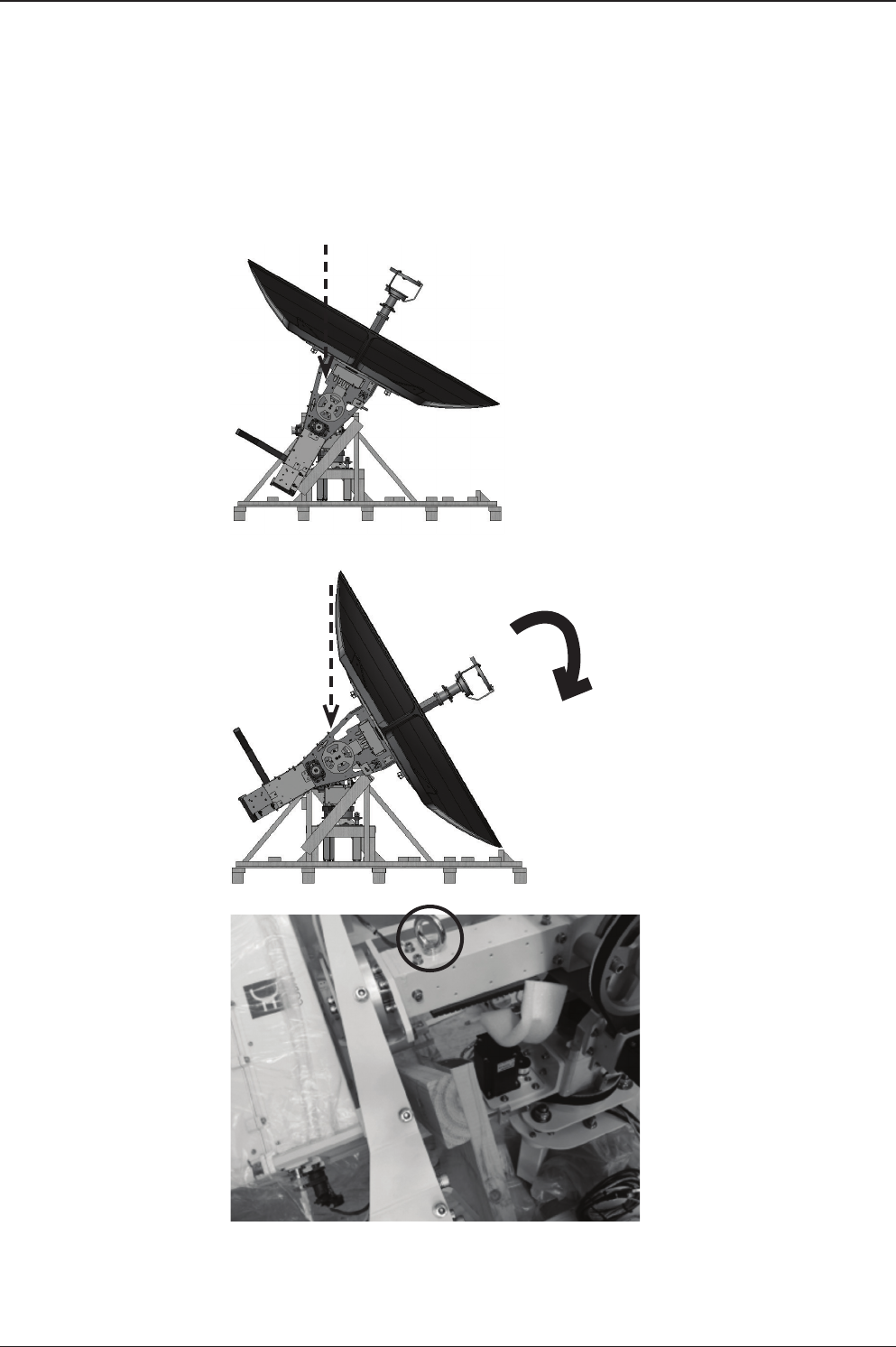
In a different view, this
is the original position
(as is in section B).
Lifting straps cannot be
attached the CL arm in
this position.
As shown in Section C,
when the tap is moved,
lifting strap can be
attached to the CL arm.
4000mm Lifting straps
should be hooked onto
the I-bolts as shown left.
There should be 2 hooks
located on CL arm.
D.
E.
F.
30° Turn

v240C – Marine Satellite Communication System
38
Securely hook the lifting
straps as shown. (On the
both side of the CL arm)
Securely hook the lifting
straps as shown. (On the
both side of the CL arm)
G.
H.

39
INSTALLING THE ANTENNA
Hook the straps to the
crane as slowly lift up the
system as shown.
Do not place the antenna
onto the post just yet.
Follow the next steps
in section 12, securing
Cables.
I.

v240C – Marine Satellite Communication System
40
Locate the power and RF
cables as shown.
Pull the cables through
the center of the pedestal
middle plate as shown on
left.
The cables need to be
inserted through the
center of the pedestal
support as indicated
A.
B.
C.
12. Securing Cables

41
INSTALLING THE ANTENNA
Place the cables through
the center hole of the
Post as shown in C.
Cables should come out
of the bottom of the post
as shown left.
D.
E.
v240C – Marine Satellite Communication System
42
13. Assembly of Upper Antenna and Post
Locate the power and RF
cables as shown.
Insert the 3 M16 x 40
bolts to secure the
antenna assembly to the
pedestal. Make sure
to apply Loctite 262
to securely tighten the
assembly.
The system should be
mounted so the AZ
sensor is on the stern
position of the base
assembly.
A.
B.
C.
BOW Direction
BOW Direction
BOW Direction

43
INSTALLING THE ANTENNA
NOTE: Bow Direction
should be the opposite of
Hatch.
Apply silicon
(Sikaex-291) to side of
radome panels before
applying bolts.
B.
C.
Now assemble the lower
radome panels. M6x35L
bolts are used for the
connection between
panels, and M6x30L bolts
are used for connection
between panels and base
frame.
M6x35L
M6x30L
A.
14. Assembly Lower Radome panels and Base Frame
v240C – Marine Satellite Communication System
44
Apply the bolts as shown
right with corresponding
sizes
Make sure to apply bolt
and nut as shown. It is
recommended that the
max torque be 15Nm.
D.
E.
45
INSTALLING THE ANTENNA
BOW
Hatch Direction
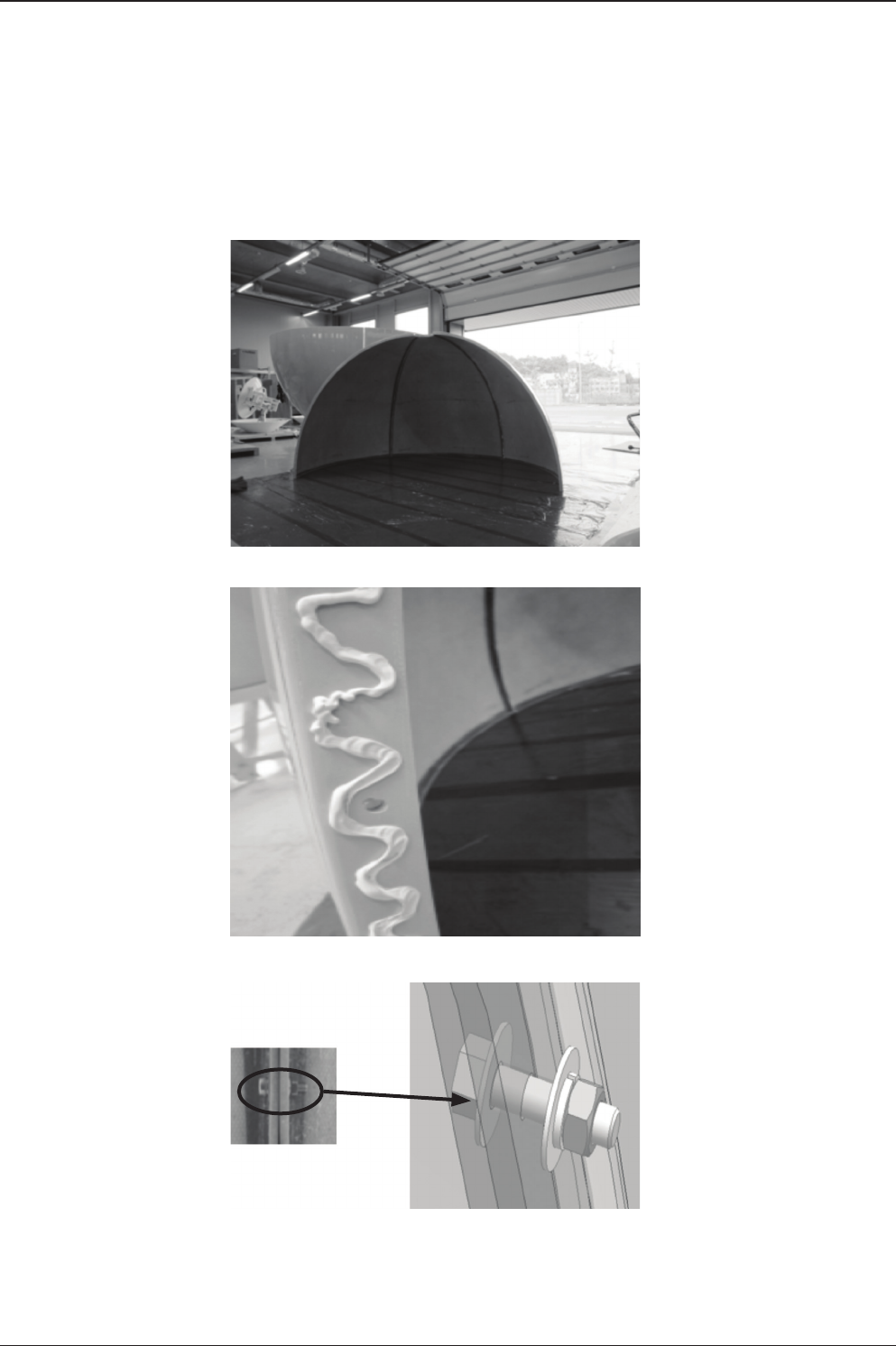
15. Assembly of Lower Radome
Make sure to tighten
all the joints before
proceeding to next step.
plus, make sure to clean
out the silicon mess to
give a smooth nish.
Direction of the hatch
should be the exactly
opposite of Bow direction.
B.
C.
Assemble 5 radome
panels as indicated in
previous section.
A.
v240C – Marine Satellite Communication System
46
Apply the silicon between
the radome panels from
the outside.
Make sure to clean out
the silicon for smooth
nish
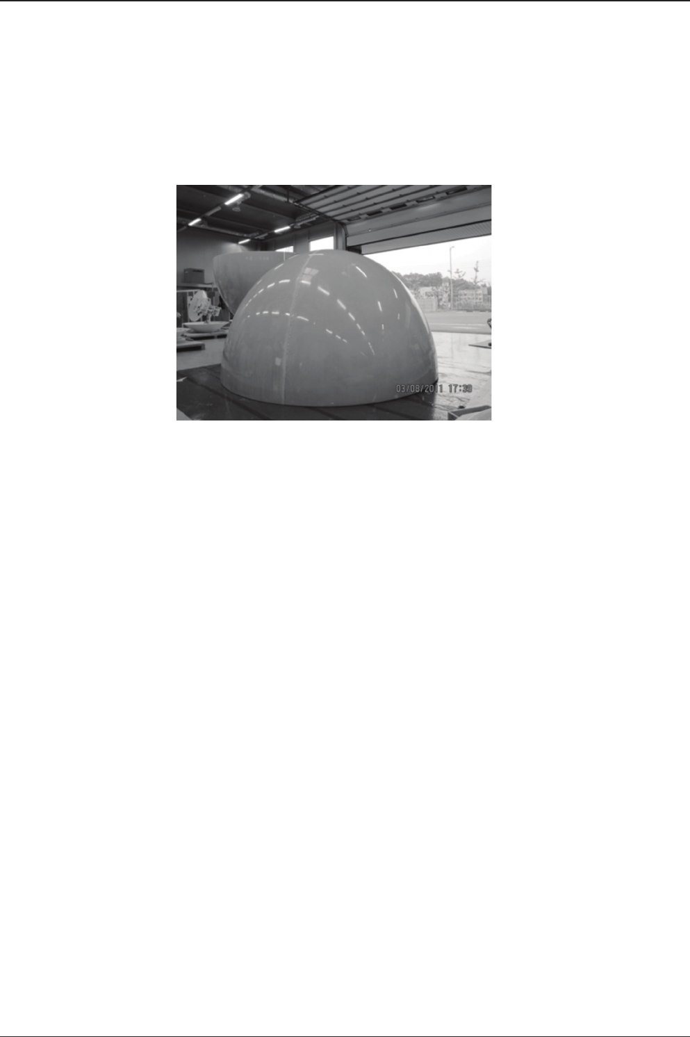
Finished lower radome
should look as shown.
A.
B.
C.
16. Applying Sillicon to Lower Radome Panels
47
INSTALLING THE ANTENNA
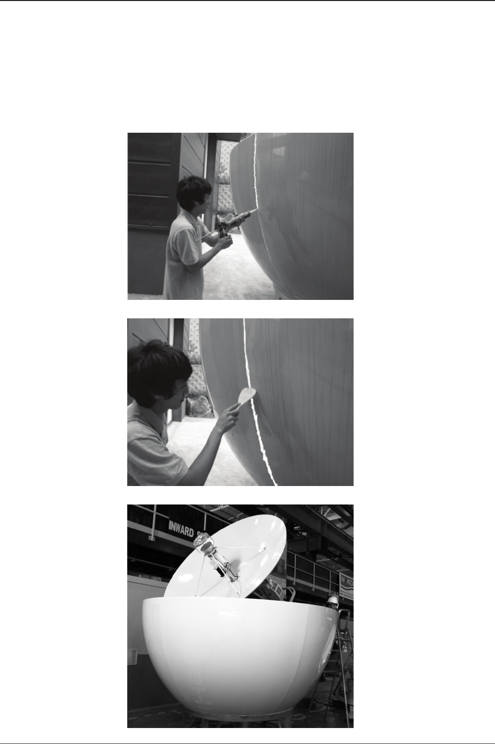
17. Assembly of Upper Radome Panels
The assembly of
the upper radome
panels should now be
completed, using the
M6 x 35 bolts supplied.
Apply silicon
(Sikaex-291) to side of
radome panels before
fastening bolts.
Make sure to apply bolt
and nut as shown. It is
recommended that the
max torque be 15Nm.
A.
B.
C.

v240C – Marine Satellite Communication System
48
18. Assembly of Upper Radome Cap and Finishing
Assemble 4 upper
radome panels as shown
left.
You are now ready to
install the radome cap.
Fix the cap in place with
a layer of silicon and
loosely fasten the M6
bolts but do not tighten
them at this time.
A.
B.
C.
49
INSTALLING THE ANTENNA
After the attachment of
the cap, the last panel
of the radome should
be installed to nish
the assembly. The nal
section is completed
with a person inside the
radome so a provision
needs to be made so they
can be released by lifting
the completed dome. At
this point all bolts should
be tightened.
Any excess silicon should
be removed to give a
clean nish.
D.

v240C – Marine Satellite Communication System
50
19. Applying Silicon to Upper Radome Panels
Apply the silicon from
the outside between the
radome panels.
Remove excess sealant
and smooth to complete
the radome top section.
A.
B.

51
INSTALLING THE ANTENNA
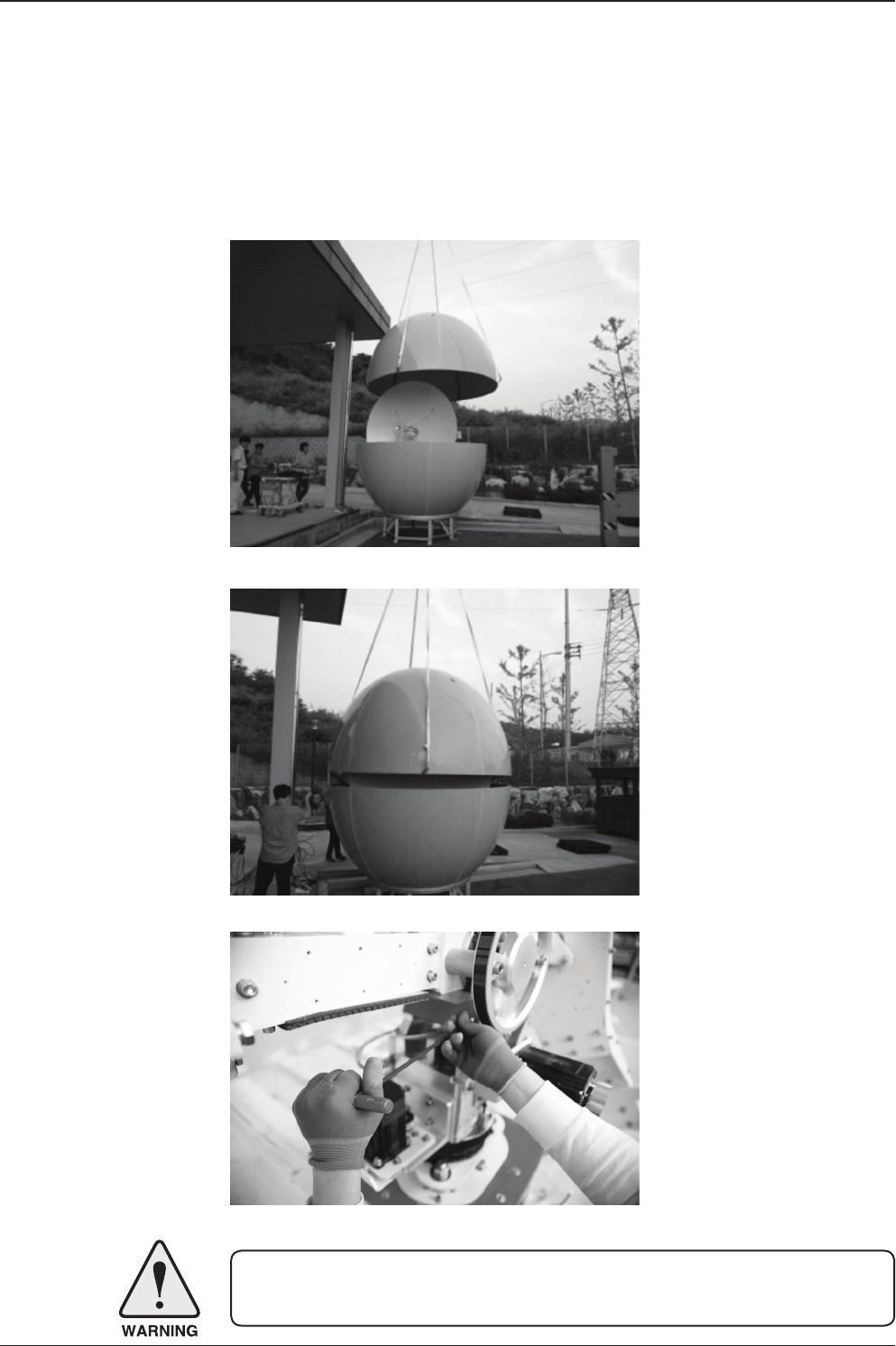
20. Final Assembly of Radome
There are 4 sets of M6x35
Hex Bolts and Nuts that
should be applied to 4
locations of the upper
radome. The assembly
shown on right should be
constructed on each of 4
locations.
Connect the lifting strap
to the radome.
Radome should be lifted
up slowly as shown by a
crane.
A.
B.
C.
v240C – Marine Satellite Communication System
52
Apply silicon to the top lip
of the lower section of the
radome then slowly place
the upper radome on to
the lower radome half.
Slowly place the upper
radome on top of the
lower radome assembly.
Once placed onto the
lower half fasten with the
supplied nuts and bolts.
Then clean off any excess
silicon.
Enter the radome hatch
and take out 2 brackets
under the CL Arm.
Remove the M6 Hex bolts
to free the CL Arm.
D.
E.
F.
WARNING: Never operate the antenna before installation is complete. Doing so may
damage the antenna system including motor control.
53
INSTALLING THE ANTENNA
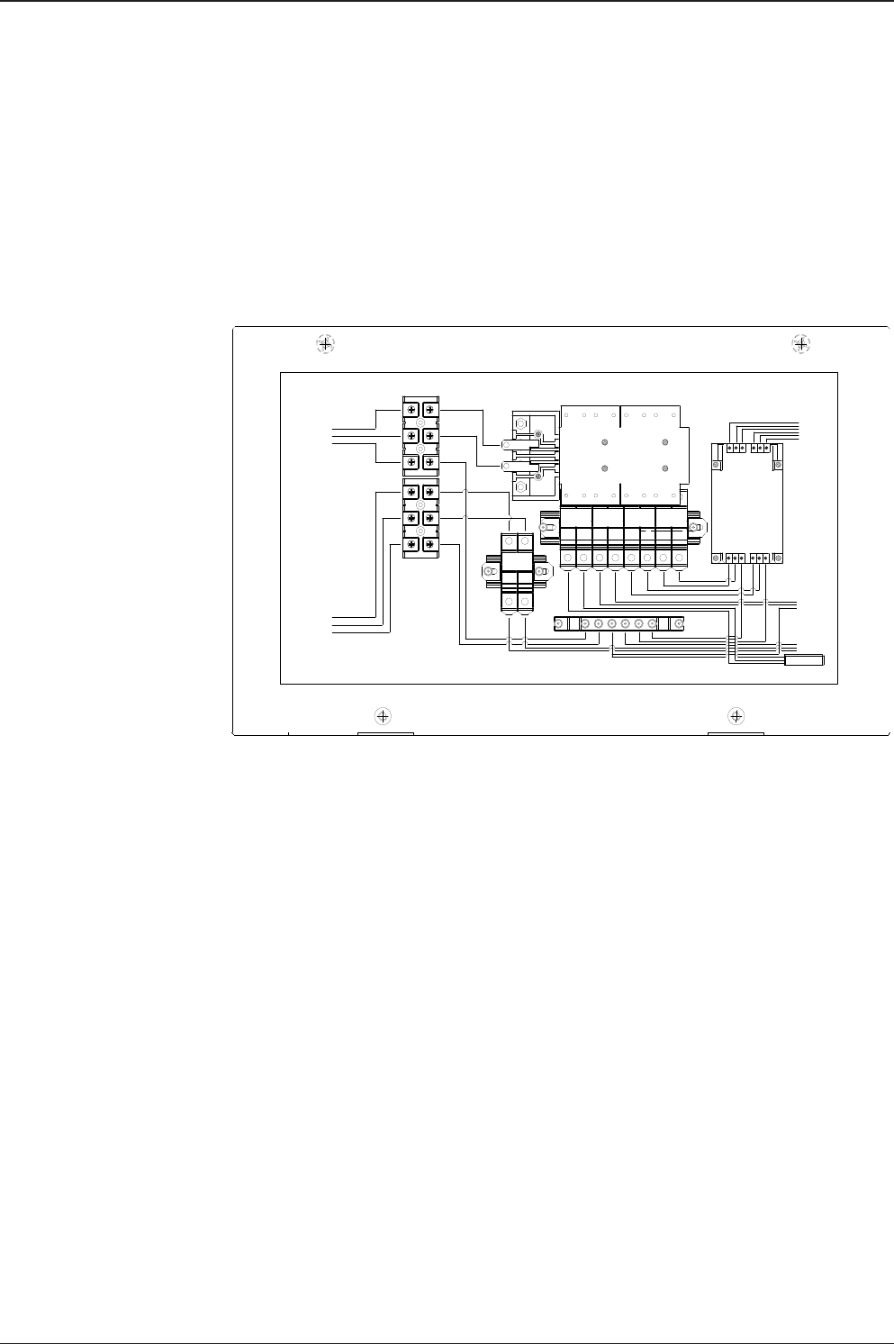
21. Power Box Connection
Connect the power cable to the power box and connect the other end into a power
supply rated at 100-240V.
Neutral
Live Live Live
Live
Light
(15A)
Extra
(10A)
BUC
(10A)
BUC
Antenna
(10A)
Live Live
F.G
F.G F. G
F.G F. G
F.G F. G F.G F.G
Green Green
Neutral
Neutral
Neutral
Neutral
Air Conditioner
(15A)
Neutral
Neutral Neutral Yellow Blue Blue
Air Conditioner
(100-240V ~ 50/60 Hz 15A)
SMPS (Light)
Yellow
Yellow
Green
Blue
Blue
Blue
Yellow
Green
Green
Yellow
Live Live
Live
F.G
Neutral
Neutral Live
Antenna
Antenna
Slip Ring
Extra
(100-240V ~ 50/60 Hz 10A)
Yellow
Green
Blue
Antenna: 100-240V ~
50/60 Hz 4A
BUC: 100-240V ~
50/60 Hz 7A
Input AC2
(100-240V ~ 50/60 Hz 15A)
Input AC1
(100-240V ~ 50/60 Hz 21A)

v240C – Marine Satellite Communication System
54

INSTALLING THE ACU
Mounting the ACU
19” Rack Mount Type
Table Mount Type
ACU Dimensions
Selection of ACU Installation Site
Ship Gyro Connection
Connecting the System with a Ship’s Gyro
Connecting the System without a Ship’s Gyro
WiFi & Bluetooth Connection
ACU Connector Guide
v240C – Marine Satellite Communication System
56
Mounting the ACU
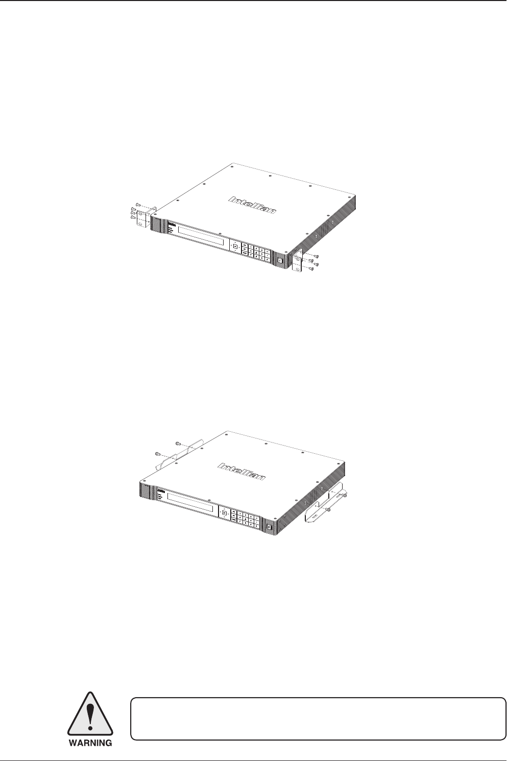
Intellian supplies two types of mounting methods (a) 19” Rack Mount Type and (b)
Table Mount Type to mount your ACU.
19” Rack Mount Type
- The ACU should be installed using the two supplied Rack Mounting Brackets
which allow for a side 19” rack mounting conguration.
- Using the Flat Head Screw supplied, attach the mounting brackets to the sides of
the ACU.
- Place the ACU in the location where it is going to be installed.
- Connect the cables to the rear of the ACU.
Table Mount Type
- The ACU should be installed using the two supplied Table Mounting Brackets
which allow for a top or bottom mounting conguration.
- Using the Sems Bolt supplied, attach the mounting brackets to the sides of the
ACU.
- Place the ACU in the location where it is going to be installed.
- Using a pencil to mark the 4 hole positions (2 on each side), and use the appropriate
drill bit to screw down the brackets.
- Connect the cables to the rear of the ACU.
WARNING: Ensure that the cables connected to the ACU are long enough to prevent
damage when the ACU is pulled out from the rack.
19" Rack Mount Type
Table Mount Type
57
INSTALLING THE ACU
Selection of ACU Installation Site
The ACU should be installed below deck, in a location that is:
• Dry, cool, and ventilated.
• The front panel should be easily accessible to the user.
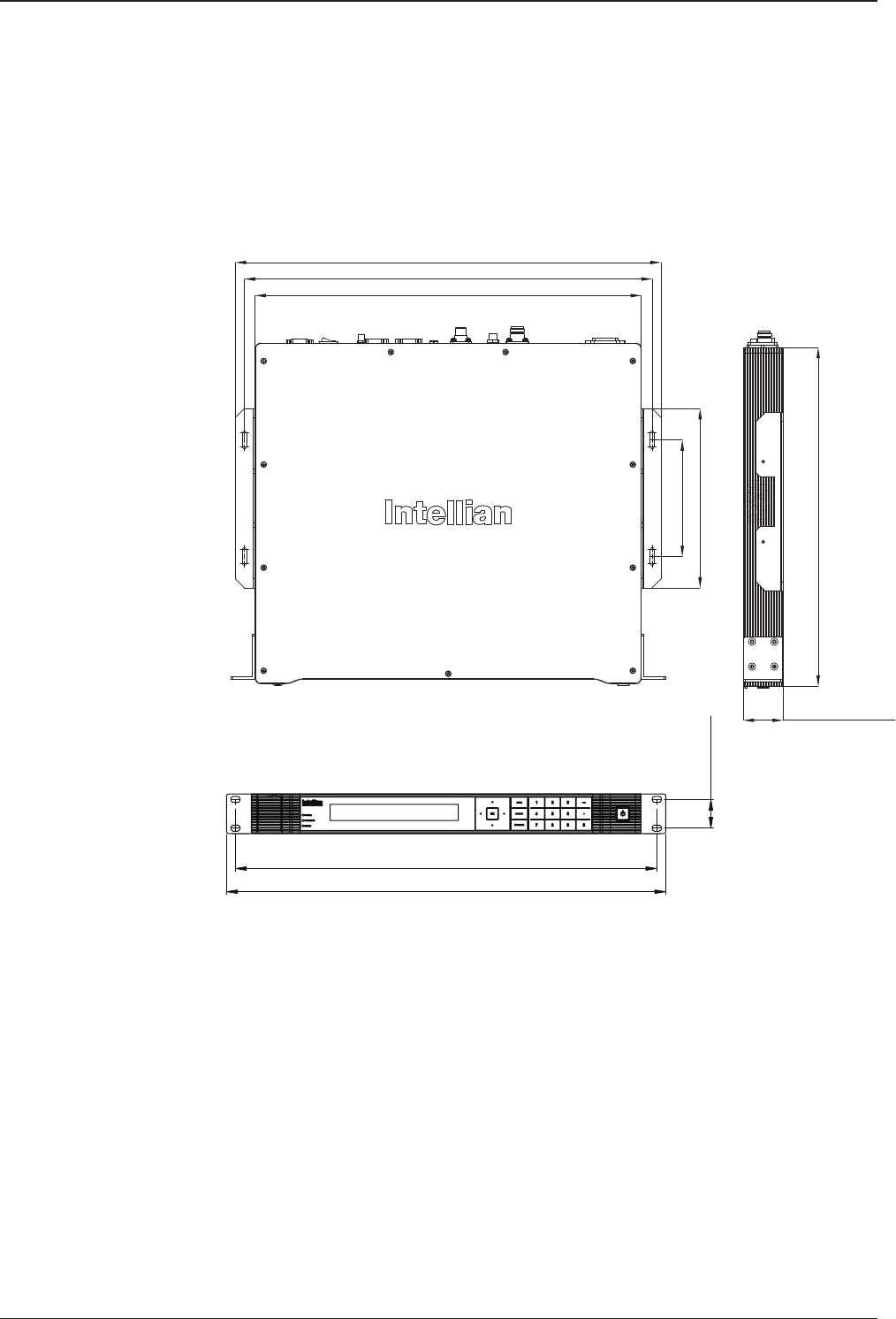
ACU Dimensions
Dimension of ACU
48.5 cm (19.1")
46.6 cm (18.4")
3.2 cm (1.3")
13.0 cm (5.1")
43.1 cm (17")
47.5 cm (18.7")
20.0 cm (7.9")
45.5 cm (17.9")
38 cm (15")
4.4 cm (1.7")
v240C – Marine Satellite Communication System
58
Ship Gyro Connection
Connecting the System with a Ship’s Gyrocompass
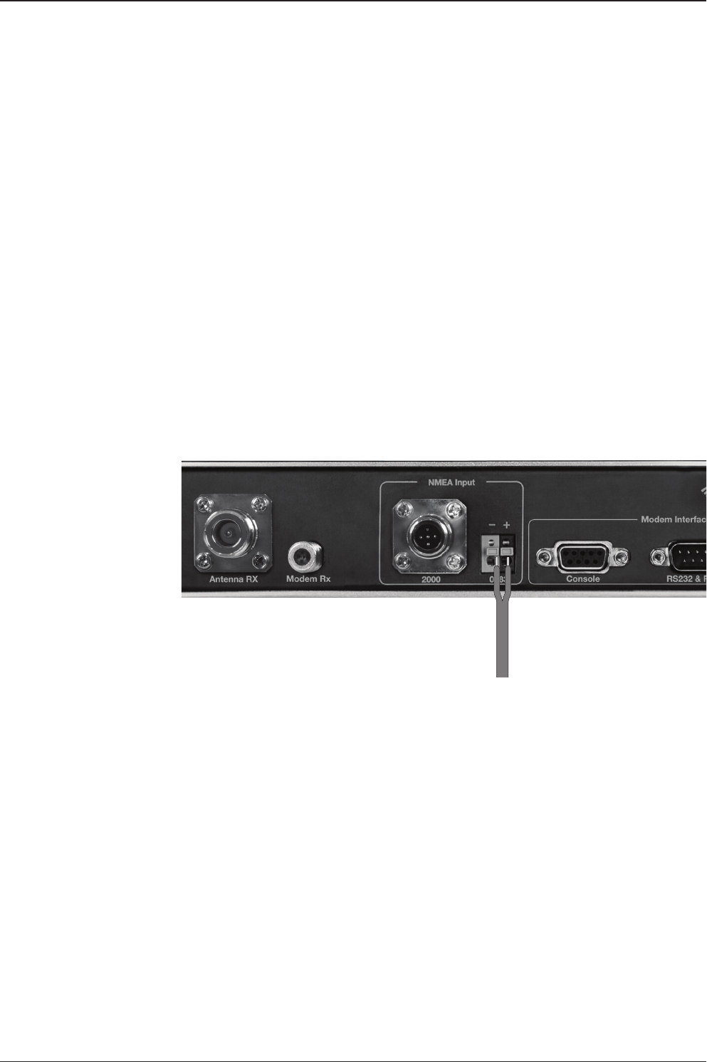
For satellite tracking, you must connect a ship’s Gyro to the antenna system through
the gyro interface on the rear of the ACU. Intellian’s ACU supports NMEA 0183 and
NMEA 2000 gyro types. If the ship’s gyrocompass output uses something different
than a NMEA 0183 or NMEA 2000, a separate purchase of a gyro converter is
required.
• NMEA 0183 Gyro Compass Interface Cable (Customer Supplied)
• Type: 2 conductors for NMEA 0183
• NMEA heading sentence: xx HDT (4800 Baud, 8, N,1)
If there is no HDT sentence then use HDM sentence instead.
• NMEA 2000 heading PGN Number = 127250 (Vessel Heading)
Strip the cable for 5 mm (0.2")
Do not solder the cable

59
INSTALLING THE ACU
Connecting the System without a Ship’s Gyrocompass
For a vessel where the ship’s gyrocompass is not installed or is difcult to connect,
the Intellian Gyro-Free satellite search function will be automatically
enabled to allow the antenna to lock onto the desired satellite without
requiring an external heading input.
The table below provides an example of the Gyro-Free satellite search algorithm. The
Search 1 or Search 3 satellite search pattern will be triggered according
to the existence of heading input and the setting of the heading device.
Search 1: The antenna will search for the target satellite by turning its azimuth
angle in a CCW(Counter Clockwise) direction until the antenna receives a
lock signal from the Modem or until the DVB(Digital Video Broadcasting)
transponder of the target satellite is decoded by the antenna.
Search 3: The antenna will search for the target satellite by turning its azimuth angle
directly to the position calculated using the ship’s heading input and lock
onto the satellite.
Quick Setup Procedure
• Set the satellite having DVB transponder as the target satellite.
• Set “No Device” to the heading device.
• The antenna will search for the target satellite by turning its azimuth angle in
a CCW direction and lock onto the satellite signal until the antenna receives a
lock signal from the Modem or until the DVB transponder of the target satellite is
decoded.
• Set the heading device as NMEA
- Enter the “Manual search” menu and press the “Function” key to save the current
settings. Intellian's ACU will automatically calculate and save the BOW offset.
- Upload the real TARGET satellite pre-congured from the library.
Setting of Heading Device
Existence of Heading Data No Device
NMEA / NMEA 2000
Ground Test
w/ Heading Data Search 1 Search 3 Search 3
w/out Heading Data Search 1 Search 1 Search 3
v240C – Marine Satellite Communication System
60
Wi-Fi and Bluetooth Connection
You can connect to the ACU via Wi-Fi and to the antenna via Bluetooth for com-
plete control and monitoring whenever you are on a vessel. For Bluetooth connec-
tion, see Appendix A: Setup Bluetooth Connection.
Set Up Wi-Fi Connection
Setting up the ACU to access Wi-Fi.
Setting up the PC (AP MENU) to access Wi-Fi.
Aptus Web Conrmation
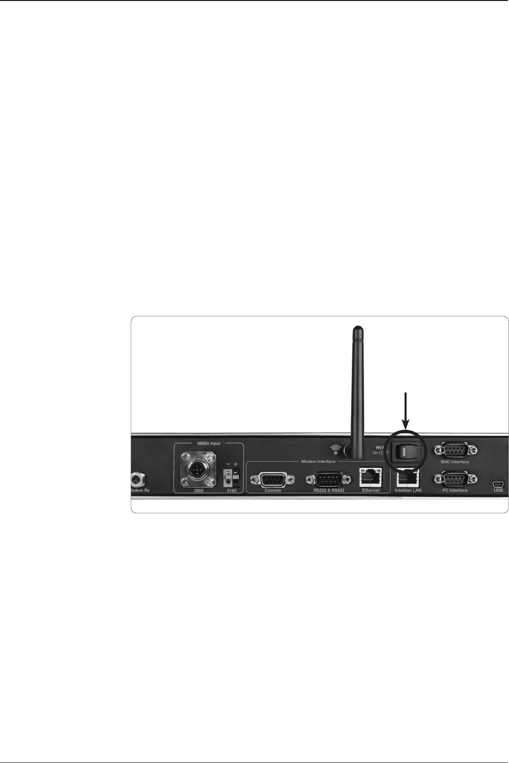
Set Up the ACU to access Wi-Fi
Turn on the switch on the back of the ACU, and 30 seconds after enabling the
power supply, conrm if a red light appears on the switch.
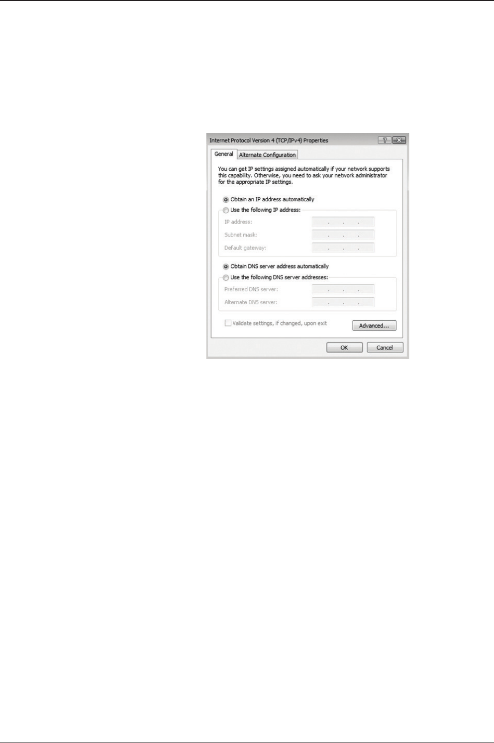
Set Up the PC to access Wi-Fi
Setting up my computer’s wireless IP address:
Control Panel > Network and Sharing Center > Change Adapter Settings >
Right click on the “Local Area Connection” > Click “Properties”
After selecting TCP/ IPv4, click on the properties menu, then select “Obtain an
IP address automatically”.
Wi-Fi On/Off
Switch
j
61
INSTALLING THE ACU
Manually change the network settings, click on “Use the following IP address”
and use the settings listed below.
Case #1
If iARM Module’s IP is known
The iARM module’s default IP is 192.168.1.223
PC IP: 192.168.1.222
Subnet Mask: 255.255.255.0
Gateway: 192.168.1.223
Case #2
If iARM Module’s IP is unknown
The iARM module’s secondary IP is 10.10.10.1
PC IP: 10.10.10.2
Subnet Mask: 255.255.255.0
Gateway: 10.10.10.1
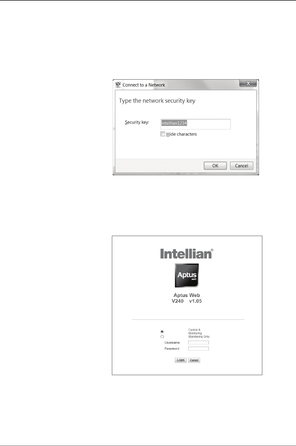
Connect Wi-Fi in AP MENU.
After clicking on the Windows Wireless Connection icon, click on
Intellian-VSAT (Default).
Enter the Network Security Key.
Key: intellian1234 (Default)
k
l
m
v240C – Marine Satellite Communication System
62
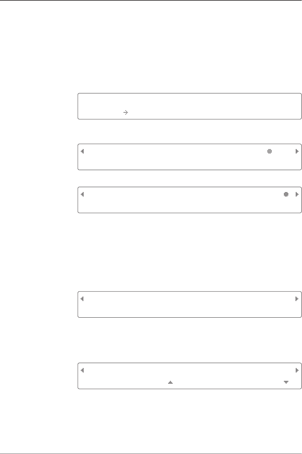
You can conrm the logo and version data by accessing http://192.168.1.223.
Login by entering the ID/ Password listed below.
Username: intellian (Default)
Password: 12345678 (Default)
When you login, make sure that all the data within every page is being displayed
correctly.
n
o

63
INSTALLING THE ACU
ACU Connector Guide
• Console Port
NOTE: NMEA GPS IN/OUT Sentence: GPGLL (4800 Baud, 8, N, 1)
12345
6789
54321
9876
12345
6789
54321
9876
12345
6789
54321
9876
Pin Signal Pin Signal
1GND 6GPS OUT -
2GPS OUT + 7Modem_SIGNAL_IN
3Modem_LOCK 8Modem_CTRL2
4Modem_CTRL1 (TX MUTE) 9GPS IN -
5GPS IN +
ACU Console Port
D-Sub 9 pin Female
D-Sub 9 pin Male connector
Supplied Component
Pin Signal Pin Signal
1-6-
2RXD 7-
3TXD 8-
4-9-
5GND
Pin Signal Pin Signal
1-6-
2RXD + 7RXD -
3TXD + 8TXD -
4-9-
5GND
D-Sub 9 pin RS232
Connector
D-Sub 9 pin RS422
Connector
• RS232/422 Connector (Modem & BUC Interface)

v240C – Marine Satellite Communication System
64
• NMEA 2000 Connector
5
4
3
21Pins
Connector Threads
5
3
4
12Sockets
Connector Threads
Pin Signal
1Shield
2NET-S, (power supply positive, +V)
3NET-C, (power supply common, -V)
4NET-H, (CAN-H)
5NET-L, (CAN-L)
Pin Signal
1Shield
2NET-S, (power supply positive, +V)
3NET-C, (power supply common, -V)
4NET-H, (CAN-H)
5NET-L, (CAN-L)
Male Connector Female Connector

OPERATING THE ACUOPERATING THE ACU
Introduction
Normal Menu
Setup Menu
Installation Settings
Antenna Settings
Manual Search
Setup Antenna LNB pol Angle
Search Parameters
Setting Antenna Parameters
Setup Block Zone
Diagnosis Procedures
Satellite Settings
Load Satellite
Edit Satellite Information
Add Satellite Information
Check NID
System Settings
Setting Local
Setting Location
Setting Modem Port
System Management
Key Lock

v240C – Marine Satellite Communication System
66
Introduction
ACU Soft Keys
Soft Key Functions
INITIALIZE - ANTENNA INFO
INTELLIAN v240
PC : PC Cable (USB)
DN : Firmware upgrade or Log data
download (USB)
Management port
Arrow
Keys
Function
OK
BACK
Number Keys
Power
Switch
MENU
Touch key Function
OK KEY Enter next step, or menu.
MENU Enter SETUP MENU
BACK
In SETUP MENU, returns to previous menu or option, or saves the
adjusted settings. In NORMAL MENU, returns to the rst page of
antenna current status.
ARROW KEYS Moves cursor to an alternative option to select, or increase and
decrease the selected character to a desired value.
FUNCTION Saves the adjusted settings.
NUMBER KEYS Inputs numbers.

67
OPERATING THE ACU
INTELLIAN TECHNOLOGIES INC.
1. The data communication is being established between the antenna and the ACU.
INITIALIZE - ANTENNA INFO
INTELLIAN v240
2. The ACU receives antenna information.
INITIALIZE - EL POSITION
INTELLIAN v240
3. The elevation angle and cross level angle are initialized.
INITIALIZE - AZIMUTH POSITION
INTELLIAN v240
4. The azimuth angle is initialized.
INITIALIZE - SAT POSITION
INTELLIAN v240
5. The antenna returns to the target satellite position.
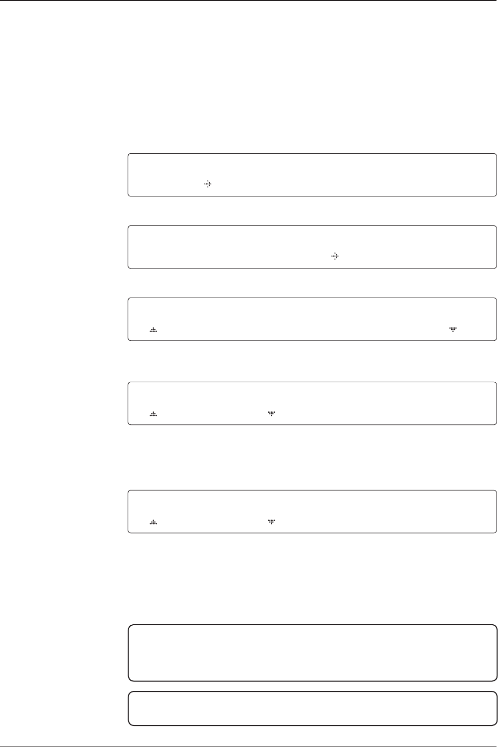
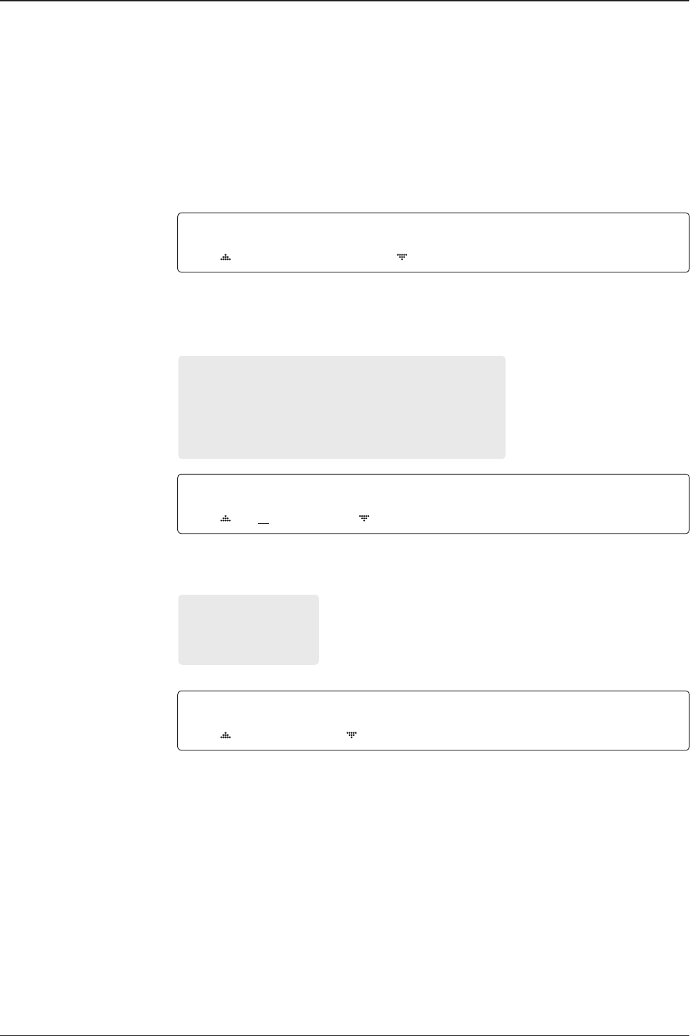
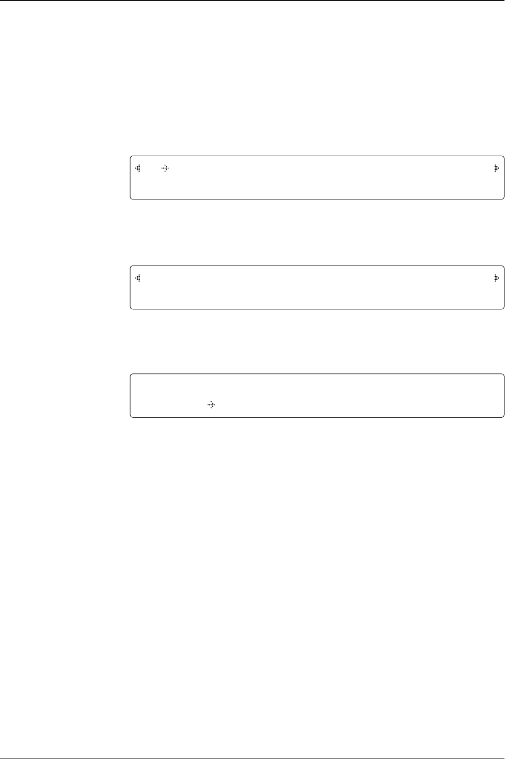
SEARCH1 125.0E ASIA6AH SIG:101
AZ:150.7( 150.7) EL: 45.3 SK: 02.0
6. The antenna is searching for the target satellite.
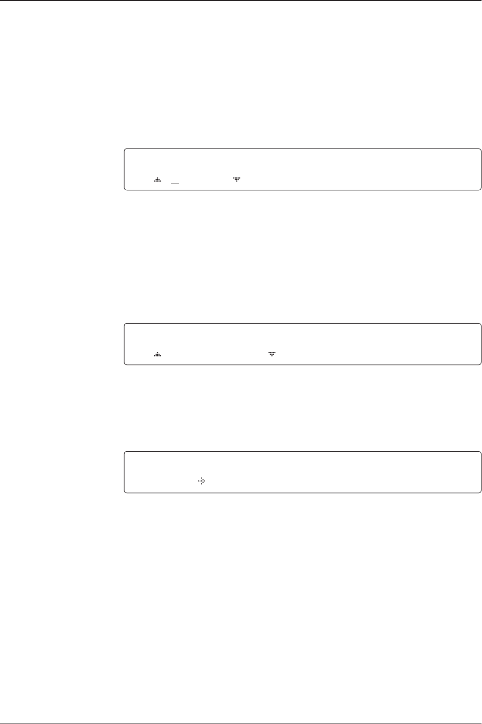
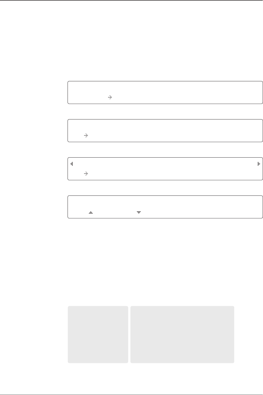
TRACKING 125.0E ASIA6H SIG:201
AZ:181.7( 181.7) EL: 47.3 SK: 02.0 Fn
7. The antenna has locked onto the satellite.
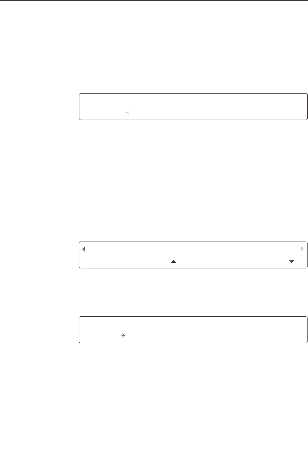
Startup
With the system installed and power applied, the ACU screen will show the following
sequence.
Normal Menu
Start up
Initialize antenna info
Initialize elevation &
cross level angle
Initialize azimuth angle
Initialize target satellite
position
Search status
Tracking status

v240C – Marine Satellite Communication System
68
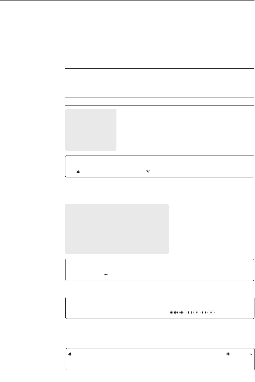
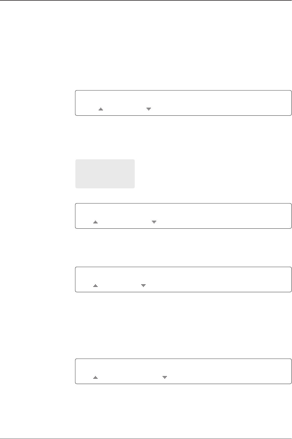
SEARCH1 125.0E ASIA6AH SIG:101
AZ:150.7( 150.7) EL: 45.3 SK: 02.0
1. The antenna is searching for the target satellite.
TRACKING 125.0E ASIA6H SIG:201
AZ:181.7( 181.7) EL: 47.3 SK: 02.0 Fn
2. The antenna has locked onto the target satellite.
Current IF signal level (SIG/ AGC) is displayed. SIG will be displayed when NBD (Narrow
band detection) mode for TRACKING SIGNAL is chosen to be used and AGC will be
displayed when DVB mode of TRACKING SIGNAL is chosen to be used.
The symbol “ ” will be only displayed when the satellite signal is strong enough to locked
onto.
True azimuth [181.7] position of the antenna is the sum of ships heading 000.0 [HDG] and
antenna relative [181.7].
Monitoring Antenna Current Status
When the ACU power is on, it displays the status of the antenna. The current status
of the antenna is displayed as shown below.
Current search status
Current tracking status
69
OPERATING THE ACU
3. Press FUNCTION key to save current BOW OFFSET information or abort and return to the
main display. "Fn" will be displayed only if the antenna is in tracking menu.
4. Press RIGHT arrow key to display NBD, GPS and ship’s heading information.
5. NBD, GPS and ship’s heading information are shown.
NBD (Narrow Band Detection) IF tracking frequency : 1070000 KHz
Detected Band Width : 1000KHz
SIG (Signal Level ): 201
W (West ) / E (East) Longitude: 4.53 ° E
N (North) / S (South) Latitude: 52.22° N
HDG (Ship’s Heading) : 000.0 degree
LNB local oscillator(LO) frequency: 5150 MHz
6. Press RIGHT arrow key to display the below information.
Antenna part number, Antenna serial number and PCU / Stabilizer rmware version.
ACU part number, ACU serial number, ACU / Pol. Controller rmware version.
Press BACK Key to return to the rst page of the antenna current status.
7. Press RIGHT arrow key to display the USB FUNCTION.
When USB Memory is connected to USB port, the above screen will be displayed
With stored FWP le in USB Memory folder, ACU can be upgraded
UPGRADE FIRMWARE: ACU is upgraded with a FWP le in designated folder of USB
Memory
COPY LOG DATA: Copies data logs to USB Memory
Tracking & Heading
information
Antenna & ACU
versions
SAVE CURRENT SAT INFO ?
YES NO
Current tracking status
Save current satellite info
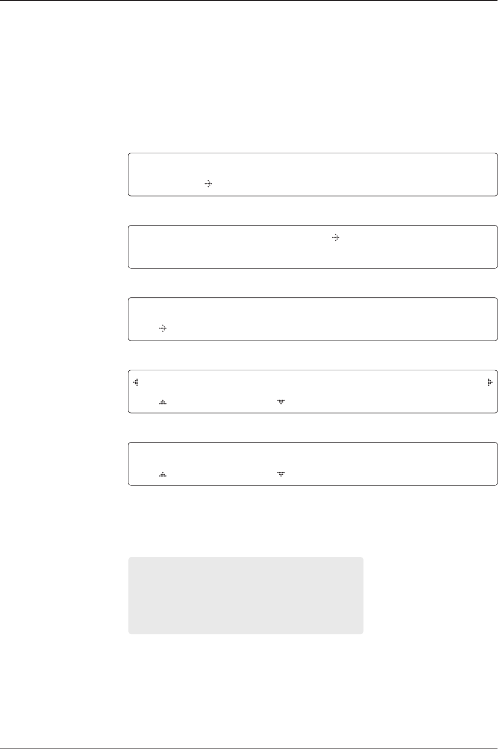
TRACKING 125.0E ASIA6H SIG:201
AZ:181.7( 181.7) EL: 47.3 SK: 02.0 Fn
NBD F:1070000 BW:1000 SIG:201
004.53E 52.22N HDG:000.0 L: 5150 Fn
V C1-241-P01 ANT. SERIAL 6.00/6.00
VP-T537 ACU SERIAL 3.00/1.00
[USB FUNCTION] SELECT USB FUNCTION
UPGRADE FIRMWARE
Select
USB
functions
v240C – Marine Satellite Communication System
70
8. Press OK key to upgrade rmware.
Refer to the error messages below if any errors occur.
UPGRADE FIRMWARE
- FIRMWARE FILE NOT FOUND: the system cannot nd the FWP le.
- INVALID FIRMWARE: the le is not in a recognizable FWP format.
- MORE THAN 1 FILE EXIST: there is more than 1 rmware le that exists from the speci
ed folder in the USB ash drive.
- CHECK USB CONNECTION: the USB ash drive is not connected.
COPY LOG DATA
- COPY LOG DATA TO USB [30%]: display the copy progress in percentages.
- NOT ENOUGH SPACE IN USB: USB occupies no memory space.
- CHECK USB CONNECTION: the USB ash drive is not connected.
9. Press RIGHT arrow key to display the real-time diagnostic result.
The real-time diagnostic code will be displayed automatically if there is any error found
during the system operation. However, this page will not be displayed if there is no error
message.
Real-time
diagnostic
result
Upgrade
the
system
[DIAGNOSTIC] SENSOR BOX
CODE109 RESULTS : FAILED FN
UPGRADE ?
YES NO
ERASE DIAGNOSTIC ERROR LOG ?
YES NO
Erase
Error message
10. Press FUNCTION key to erase diagnostic error message.

71
OPERATING THE ACU
Setup Mode
Enter the SETUP Mode simply follow the instructions below.
Searching / Tracking Menu
Enter password
Setup Menu
Exit setup Menu
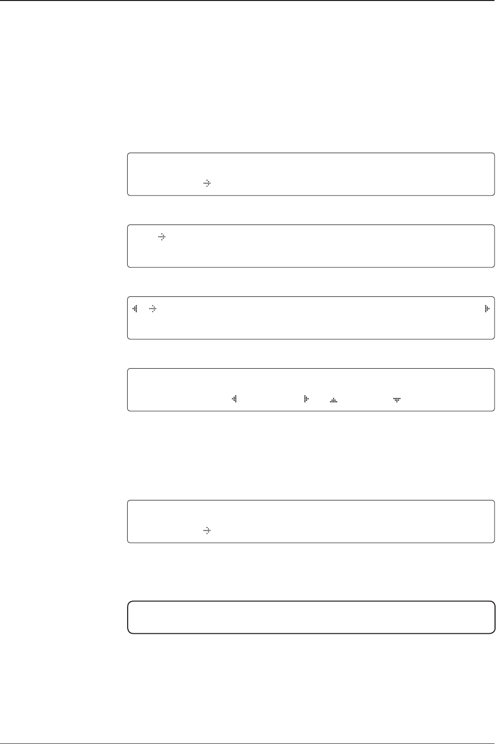
TRACKING 125.0E ASIA6AH SIG:201
AZ:183.7( 183.7) EL: 47.3 SK: 02.0 Fn
1. While the antenna is in SEARCHING / TRACKING MENU, press MENU key to enter SETUP
Mode. * indicates the key pad lock function is on (Refer to KEY LOCK Menu to setup the key
pad lock function). When key pad lock function is activated press MENU key or when “Fn”
Menu is activated press FUNCTION key the ENTER PASSWORD Menu will be displayed.
ENTER PASSWORD
- - - -
2. If the key pad lock function is on, enter the password before accessing SETUP Menu. If the
key pad lock function is off, access SETUP Menu directly by following Step 3.
SETUP MODE ?
YES NO
3. Press LEFT arrow key to move cursor to YES and press OK key to enter SETUP Menu or
press RIGHT arrow key to move cursor to NO and press OK key to abort and return to the
main display.
EXIT SETUP MODE ?
YES NO
4. While the antenna is in SETUP Menu, press FUNCTION key as a shortcut key to exit
SETUP Menu.
v240C – Marine Satellite Communication System
72
Installation Settings
During the rst time installation, it is required to setup the installation settings.
Installation Menu
Latitude & Longitude
Gyro type
Select satellite
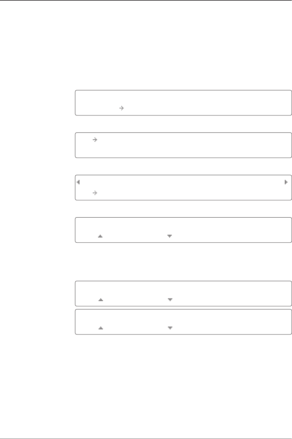
Setup Mode SETUP MODE ?
YES NO
1. Press LEFT arrow key to move cursor to YES and press OK key to enter SETUP Mode.
+ANTENNA +SATELLITE
+SYSTEM +INSTALLATION
2. Press arrow keys to move cursor to INSTALLATION menu and press OK key to enter it.
SELECT SATELLITE
[1] ASIA6AH 125.00E
3. Press UP and DOWN arrow keys to select the satellite that you wish to track and press OK
key to load the selected satellite.
LATITUDE LONGITUDE
37.00N 126.53E
4. Set the current LATITUDE and LONGITUDE
Press LEFT and RIGHT arrow keys until the desired character is underscored (selected).
Press UP and DOWN arrow keys to increase or decrease the value. Or press NUMBER keys
to set the desired value directly. Press OK key to set the parameter.
GYRO TYPE BOW OFFSET
NMEA 000
5. Set the ship’s GYRO TYPE* and BOW OFFSET.
A search pattern 1 or 3 will be initiated according to which Gyro Type is selected and the
existence of the gyro input. Ensure that the supported Gyro Type is set correctly.
For v240, if the ship’s gyrocompass output is
Step-by-Step (SBS) or Synchro, separate purchase of a gyro converter is required.
NOTE: A search pattern 1 will be initiated automatically if the gyro input does not exist and the gyro
type is selected other than GROUND test.
The BOW OFFSET is to offset the angle difference between the antenna’s bow and the ship’s bow
(Range: 0-360°)
NOTE: The bow offset will not be saved automatically if Search 1 pattern is initiated. In this case,
the antenna will need to retarget the desired satellite using Search 1 every time if the antenna restarts.
73
OPERATING THE ACU
6. Set MODEM TYPE * and LNB LOCAL.
MODEM TYPE is to select a proper data communication port on the ACU to interface with
the satellite Modem.
Set Modem type
and LNB local frequency
GYRO TYPE* (V240)
• NO DEVICE
• NMEA
• NMEA 2000
• GROUND TEST
Gyro search Mode Setting of Heading Device
Existence of Heading Data No
Device
NMEA
NMEA 2000
Ground Test
With Heading Data Search 1 Search 3 Search 3
Without Heading Data Search 1 Search 1 Search 3
MODEM TYPE LOCAL FREQ.
IDIRECT-I/O 0 5150MHz
LOADING ...
DO NOT TURN OFF !
8. Setting is being loaded to the system.
The ACU will restart the system automatically after uploading the setting.
DO NOT TURN OFF ACU POWER while data is being uploaded.
Loading settings
LOAD ?
YES NO
7. Press BACK key to load the current setting or abort and return to the main display.
Load
MODEM TYPE*
• USER SETTING
• IDIRECT-I/O
• IDIRECT-AMIP
• COMTECH-I/O
• COMTECH-ROSS
• HUGHES
• SATLINK-SERIAL
• SATLINK-VACP
• ELEKTRIKOM-AMIP
• GILAT-SERIAL
• IPSTAR-SOTM
TRACKING 125.0E ASIA6AH SIG:201
AZ:183.7( 183.7) EL: 47.3 SK: 03.0 Fn
9. Antenna has locked onto the target satellite.
Tracking status
v240C – Marine Satellite Communication System
74
Antenna Settings
Manual Search
Search the desired satellite manually.
Antenna movement
Setup Mode
Save
Manual search Menu
Antenna Menu
SETUP MODE ?
YES NO
1. Press LEFT arrow key to move cursor to YES and press OK key to enter SETUP Mode.
+ANTENNA +SATELLITE
+SYSTEM +INSTALLATION
2. Press OK key to enter ANTENNA Menu.
+MANUAL SEARCH +SET POL ANGLE
+SEARCH PARAM +SET PARAMETERS
3. Press OK key to enter MANUAL SEARCH Menu.
STEP SIZE AZIMUTH ELEVATION AGC
# 00.2 # 231.7 48.3 301 Fn
4. Current IF tracking signal level (AGC) / (SIG) is displayed to assist you in manually peaking
AZIMUTH (0°-360°) and ELEVATION (0°-90°) angle for best signal level.
Press NUMBER key to change the STEP SIZE (Range: 0.1~99.9). Press LEFT and RIGHT
arrow keys to increase or decrease the azimuth angles. Press UP and DOWN arrow keys to
increase or decrease the elevation angles.
Press FUNCTION key to save current settings or abort and return to the main display.
SAVE CURRENT SAT INFO?
YES NO
5. If the current settings are able to locate the satellite, press FUNCTION key to save “current
satellite information”. This will help to reduce the satellite acquisition time after restarting
the system. Press LEFT arrow key to move cursor to YES and press the OK key to save the
settings.
NOTE: If the gyro type is not NMEA or the gyro is not connected to the ACU, the information
cannot be saved.

75
OPERATING THE ACU
Setup Antenna LNB pol Angle
Setup Mode
Set pol angle Menu
Antenna Menu
LNB pol angle Signal
SETUP MODE ?
YES NO
1. Press LEFT arrow key to move cursor to YES and press OK key to enter SETUP Mode.
+ANTENNA +SATELLITE
+SYSTEM +INSTALLATION
2. Press OK key to enter ANTENNA Menu.
+MANUAL SEARCH +SET POL ANGLE
+SEARCH PARAM +SET PARAMETERS
3. Press RIGHT arrow key to move cursor to SET POL ANGLE Menu and press OK key to
enter it.
4. Press UP and DOWN arrow keys to select the LNB pol angle Menu and press OK key
to run the selected operation ‘ CALIBRATION ‘ or ‘ MANUAL ADJUST‘. Select MANUAL
ADJUST to control LNB pol angle manually. If the control board, skew potentiometer or belt
is replaced, select CALIBRATION to calibrate LNB pol angle.
5. Press UP and DOWN arrow keys to increase or decrease the LNB pol angle manually and
the correspondent SIGNAL level will be displayed next to it. If antenna has a circular & linear
polarization, POLARITY option will appear. Then with LEFT/RIGHT keys, Linear/RHCP/LHCP
can be selected.
Press BACK key to return to the main display.
NOTE: LNB POL ANGLE Menu will be displayed only if MANUAL ADJUST is selected.
SELECT L NB POL.ANGLE M ENU
CALIBRATION
LNB POL ANGLE POLARITY SIGNAL:180
20 LINEAR
v240C – Marine Satellite Communication System
76
Search 3 range
Search 1 range
Search Parameters
Setup Mode
Manual search Menu
Antenna Menu
Search param
SETUP MODE ?
YES NO
1. Press LEFT arrow key to move cursor to YES and press OK key to enter SETUP Mode.
+ANTENNA +SATELLITE
+SYSTEM +INSTALLATION
2. Press OK key to enter ANTENNA Menu.
+MANUAL SEARCH +SET POL ANGLE
+SEARCH PARAM +SET PARAMETERS
3. Press DOWN arrow keys to move cursor to SEARH PARAM and press OK key to it.
SEARCH WAIT TIME INCREMENT STEP
030 0.50
4. Set SEARCH WAIT TIME and INCREMENT STEP
Set the time-out for automatic initiation of a search after the signal level drops below the
predened threshold value (Range : 1 - 120 sec) and set increment step size (Range : 0.01
– 5.00 sec).
SEARCH1 AZ SEARCH1 EL
400 06
SEARCH3 AZ SEARCH3 EL
003 04
5. Set SEARCH 1 and 3 AZ (Azimuth) range and EL (Elevation) range. SEARCH 2 is reserved
for future use.
77
OPERATING THE ACU
-3°
-2°
-1°
0°
1°
2°
3°
1 5 10 15 20 3025
Search 1 (Gyro Free) Search Pattern
Target Satellite EL Position
Revolution (AZ direction)
REMARKS:
A search pattern 1 or 3 will be initiated according to which GYRO TYPE is selected
and the existence of the gyro input.
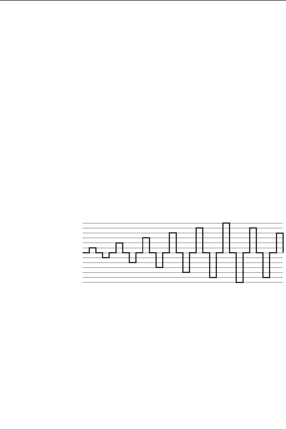
Search 1: a search pattern 1 will automatically be initiated when the ship’s heading
input does not exist / is failed. The antenna will go to the relative azimuth position 0º
at the calculated elevation and search in the azimuth CCW direction and search up
+0.5º & down -0.5º with a total of 6º(±3º) in elevation. The search cycle will repeat
until the antenna receives the lock signal from the Modem or the DVB transponder
of the target satellite is decoded by the antenna. If the desired signal is found and
above the predened detect level, the ACU will enter to Search 3. However, if the
desired signal is above the predened tracking threshold level, the antenna will
not initiate a Search 3 pattern but will go into TRACKING menu immediately. If the
detected signal is below the predened tracking threshold level, the search 1 will
repeat and start 3º away from the current position.

v240C – Marine Satellite Communication System
78
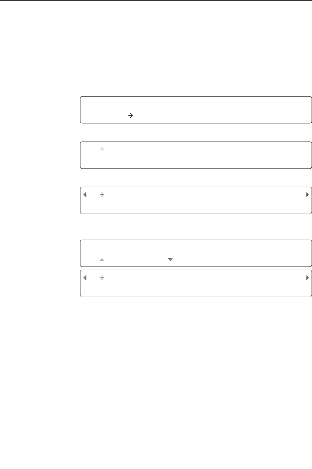
Search 3 pattern
Search 3: a search 3 pattern will automatically be initiated when AGC / SIG falls
below the current tracking level threshold value. If the desired signal is found and
above the predened tracking level, the ACU will terminate Search 3 and go into
TRACKING Menu. A search pattern will automatically be initiated when AGC / SIG
falls below the current threshold setting (this indicates that satellite signal has been
lost). The search patterns are conducted in a two-axis pattern consisting of alternate
movements in azimuth (AZ) and elevation (EL) (like its forming an expanding square
indicated within the diagram below).
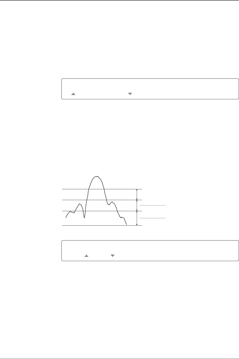
Search 1 antenna motion
Elevation
(EL) Range
0.5˚
Azimuth (AZ) Range
Target EL Angle 0°
Turn 1
Target EL Angle 0°
Turn 3
Target EL Angle + 0.5°
Turn 2
Target EL Angle - 0.5°
Turn 4
79
OPERATING THE ACU
Password
Antenna Menu
Set parameters Menu
Setup Mode
Set detect & tracking DVB
Setting Search Parameters
SETUP MODE ?
YES NO
1. Press LEFT arrow key to move cursor to YES and press OK key to enter SETUP Mode.
+ANTENNA +SATELLITE
+SYSTEM +INSTALLATION
2. Press OK key to enter ANTENNA MENU.
+MANUAL SEARCH +SET POL ANGLE
+SEARCH PARAM +SET PARAMETERS
3. Press arrow keys to move cursor to SET PARAMETERS Menu and press OK key to enter it.
ENTER PASSWORD
- - - -
4. Press 4 digit password to enter SET PARAMETERS MENU (1590).
Setup parameters is only required after installation or repairs of your antenna system.
These parameters should only be changed by an authorized service technician.
Improper setting of these parameters will render your system inoperable.
DETECT DVB TRACKING DVB
040 020
5. Set DETECT DVB and TRACKING DVB when DVB Menu of TRACKING SIGNAL is chosen
to be used (Range: 1-200).
DETECT DVB is to set the satellite signal detection level and TRACKING DVB is to set the
satellite signal tracking level.
Press LEFT and RIGHT arrow keys until the desired character is underscored (selected).
Press UP and DOWN arrow keys to increase and decrease the selected character.
Or press NUMBER keys to set the desired value directly. Press OK key to set the parameter.
Press BACK key to select the parameter you wish to edit and press BACK key again to save
or abort and return to the main display.
v240C – Marine Satellite Communication System
80
Detect & tracking level
Set detect & tracking NBD
BOW & EL adjust
DETECT NBD TRACKING NBD
040 020
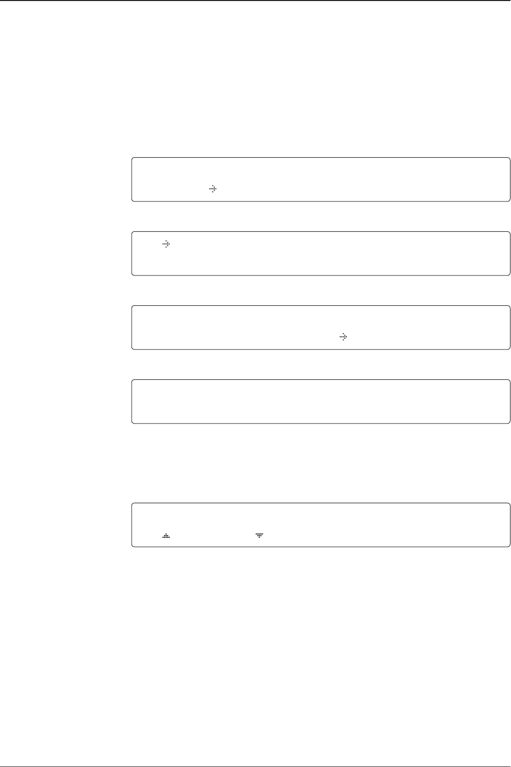
6. Set DETECT NBD and TRACKING NBD when NBD (Narrow band detection) MENU of
TRACKING SIGNAL is chosen to be used (Range: 1-200).
DETECT NBD is to set the satellite signal detection level and TRACKING NBD is to set the
satellite signal tracking level.
Press LEFT and RIGHT arrow keys until the desired character is underscored (selected).
Press UP and DOWN arrow keys to increase and decrease the selected character.
Or press NUMBER keys to set the desired value directly. Press OK key to set the parameter.
Press BACK key to select the parameter you wish to edit and press BACK key again to save
or abort and return to the main display.
Noise Level
Detect Level
Tracking Level
TRACKING DVB/NDB
Peak Level
DETECT DVB/NDB
BOW OFFSET EL.ADJUST
000 +0.0
7. Set BOW OFFSET and EL. ADJUST
BOW OFFSET is to offset the angle difference between the antenna’s bow and the ship’s bow
(Range: 0 – 360°) and EL. ADJUST is to offset the angle difference between the mechanical
elevation angle and actual elevation angle (Range: ± 5°).
Press LEFT and RIGHT arrow keys until the desired character is underscored (selected).
Press UP and DOWN arrow keys to increase and decrease the selected character.
Or press NUMBER keys to set the desired value directly. Press OK key to set the parameter.
Press BACK key to select the parameter you wish to edit and press the BACK key again to
save or abort and return to the main display.

81
OPERATING THE ACU
Select operation
process OPERATION
SAVE
8. Set OPERATION
Press UP and DOWN arrow keys to select OPERATION* items.
OPERATION*
• SAVE: save and execute the current settings.
• IDLE ON/OFF: the motor brakes will be released while IDLE Menu is ON. The
antenna will restart automatically if IDLE menu is re-set from ON to OFF touch BACK
key is pressed to exit SETUP Mode.
• REBOOT: the antenna will restart automatically if REBOOT ANTENNA is ON.
v240C – Marine Satellite Communication System
82
Setup Block Zone
Up to 5 block or radiation hazard zones can be programmed with relative azimuth
and elevation sectors.
Block zone Menut
Block zone range
Block zone 1
Antenna Menu
Setup Mode SETUP MODE ?
YES NO
1. Press LEFT arrow key to move cursor to YES and press OK key to enter SETUP Mode.
+ANTENNA +SATELLITE
+SYSTEM +INSTALLATION
2. Press OK key to enter ANTENNA Menu.
+BLOCK ZONE +DIAGNOSTIC
3. Press RIGHT arrow key to move cursor to BLOCK ZONE menu and press OK key to enter
it. Up to 5 block zones are allowed to be programmed.
ZONE 1 BLOCK
ON
AZ.1 START AZ.1 END EL.1 LIMIT
000 000 90
4. Set ZONE 1 BLOCK
Press UP and DOWN arrow keys to select “ON” to setup the block zone for ZONE 1.
Press OK key to use ZONE 1 BLOCK and set the zone 1 block range.
Press BACK key to select the parameter you wish to edit and press the BACK key again to
save or abort and return to the main display.
Set the AZ.1 START, AZ.1 END and EL.1 LIMIT while ZONE 1 BLOCK is ON.
This is the clockwise of the two points. AZ.1 START is where the relative azimuth starts
and AZ.1 END is where the relative azimuth ends (Range: 0- 360°). EL.1 Limit is where the
elevation starts (Range 0- 90°).
Press LEFT and RIGHT arrow keys until the desired character is underscored (selected).
Press UP and DOWN arrow keys to increase and decrease the selected character.
Or Press NUMBER keys to set the desired value directly. Press OK key to set the parameter.
Press BACK key to select the parameter you wish to edit and press BACK key again to save
or abort and return to the main display.

83
OPERATING THE ACU
Block zone 2
Save
ZONE 2 BLOCK
OFF
5. ZONE 2 to ZONE 5 BLOCK setting is same as ZONE 1 BLOCK.
Press OK key to set ZONE 2 BLOCK and set next parameter.
SAVE ?
YES NO
6. Press LEFT arrow key to move cursor to YES and press OK key to save and execute the
current settings. Or press RIGHT arrow key to move cursor to NO and press OK key to abort
and return to the main display.

v240C – Marine Satellite Communication System
84
Diagnossis Procedures
Refer to the diagnostic codes for the test results.
Single diagnostic
test result
Full diagnostic
test result
Diagnostic Menu
Antenna Menu
Setup Mode SETUP MODE ?
YES NO
1. Press LEFT arrow key to move cursor to YES and press OK key to enter SETUP mode.
+ANTENNA +SATELLITE
+SYSTEM +INSTALLATION
2. Press OK key to enter ANTENNA menu.
+BLOCK ZONE +DIAGNOSTIC
3. Press arrow keys to move cursor to DIAGNOSTIC menu and press OK key to enter it.
DIAGNOSTIC COMMUNICATION
FULL TEST READY
4. Press UP and DOWN arrow keys to select a full diagnostic test or single diagnostic test
and press OK key to execute the selected diagnostic test.
Menus for diagnostic are FULL TEST and CODE 101 ~ CODE 116.
DIAGNOSTIC FULL TESTING
FULL TEST - -
5. A full diagnostic is successfully completed.
DIAGNOSTIC COMMUNICATION
CODE 101 RESULT : PASSED
6. A single diagnostic test is successfully completed.

85
OPERATING THE ACU
Diagnosis Code:
CODE 101: The data communication between the antenna and the ACU is tested.
CODE 102: The azimuth motor is tested.
CODE 103: The elevation motor is tested.
CODE 104: The cross-level motor is tested.
CODE 105: The azimuth encoder is tested.
CODE 106: The cross-level encoder is tested.
CODE 107: The rate sensor is tested.
CODE 108: The tilt sensor is tested.
CODE 109: The sensor box motor is tested.
CODE 110: The LNB/NBD is tested.
CODE 111: The LNB pol motor is tested.
CODE 112: The sub-reector is tested. (Skip for v-Series communication products)
CODE 113: The antenna power is tested.
CODE 114: The ACU power is tested.
CODE 115: The receiver power is tested.
(Skip for v-Series communication products)
CODE 116: The home sensor is tested.
An example of test result: •2••••••••••-••-
•: test is passed
2: test is failed (CODE102)
–: test is skipped (TVRO products only)
?: test is in process

v240C – Marine Satellite Communication System
86
Satellite Settings
Load Satellite
Load
Load sat Menu
Load satellite
Satellite Menu
Setup Mode SETUP MODE ?
YES NO
1. Press LEFT arrow key to move cursor to YES and press OK key to enter SETUP Mode.
+ANTENNA +SATELLITE
+SYSTEM +INSTALLATION
2. Press RIGHT arrow key to move cursor to SATELLITE and press OK key to enter it.
+LOAD SAT. +EDIT SAT.
+ADD SAT. +CHECK NID
3. Press OK key to enter LOAD SAT. menu.
LOAD SATELLITE
[1] C ASIA6AH 125.0E
4. Press UP and DOWN arrow keys to select satellite that you wish to track.
Press OK key to load the selected satellite.
LOAD ?
YES NO
5. Press LEFT arrow key to move cursor to YES and press OK key to load the selected
satellite and execute the current settings. Or press RIGHT arrow key to move cursor to NO
and press OK key to abort and return to the main display.

87
OPERATING THE ACU
Edit Satellite Information
Edit satellite
Edit longitude & name
Edit sat Menu
Satellite Menu
Setup Mode SETUP MODE ?
YES NO
1. Press LEFT arrow key to move cursor to YES and press OK key to enter SETUP mode.
+ANTENNA +SATELLITE
+SYSTEM +INSTALLATION
2. Press RIGHT arrow key to move cursor to SATELLITE and press OK key to enter it.
+LOAD SAT. +EDIT SAT.
+ADD SAT. +CHECK NID
3. Press RIGHT arrow key and OK key to enter EDIT SAT. menu.
EDIT SATELLITE
[1] C ASIA6AH 125.0E
4. Press UP and DOWN arrow keys to select the satellite that you wish to edit and press OK
key to edit the selected satellite.
LONGITUDE EDIT NAME
125.00E ASIA6AH
5. Edit satellite orbit position, LONGITUDE and satellite NAME.
v240C – Marine Satellite Communication System
88
DVB VERIFY SKEW OFFSET
DVB DECODE +0.0
6. Edit satellite DVB VERIFY* method and SKEW OFFSET.
DVB VERIFY will be only activated and applied when DVB mode of TRACKING SIGNAL is
chosen to be used. Press UP and DOWN arrow keys to select DVB VERIFY and press OK
key to set the parameter.
DVB VERIFY*
• AGC – use signal level for satellite tracking.
• DVB Lock – use DVB Lock for satellite tracking.
• DVB Decode – use DVB Decode for satellite tracking.
• DSS Decode – use DSS Decode for satellite tracking.
SELECT LOCAL TRACK SIGNAL
05150MHZ NBD
7. Set SELECT LOCAL* frequency and TRACKING SIGNAL*.
Press LEFT and RIGHT arrow keys until the desired character is underscored (selected).
Press UP and DOWN arrow keys to select the LNB local frequency from the installed LNB.
RX POL TX POL
HORI. VERT.
8. Set RX POL and TX POL
To select the polarity for both RX (receive ) and TX (transmit ).
Press UP and DOWN arrow keys to select VERTICAL, HORIZONTAL, RHCP, or LHCP.
Press OK key to set the parameter.
DVB verifiy method
Set polarity
Set LNB local frequency
TRACKING SIGNAL*
• NBD
• DVB
89
OPERATING THE ACU
Set NBD tracking
frequency
Save
Set DVB tracking
frequency DVB FREQ. SYMBOL NID
04080MHz 27500KSps 0X0888
9. Set DVB FREQUENCY, SYMBOL RATE and NID when DVB MENU of TRACKING SIGNAL
is chosen to be used.
45,000 is the maximum allowed symbol rate value. NID (network ID) range is from 0 x 0000
to 0 x FFFF (hexadecimal digit).
Press LEFT and RIGHT arrow keys until the desired character is underscored (selected).
Press UP and DOWN arrow keys to increase or decrease the value.
Or press NUMBER keys to set the desired value directly.
Press OK key to set the parameter.
NBD FREQ. BANDWIDTH
1070.000MHz 01.000MHz
10. Set NBD IF FREQUENCY and BANDWIDTH when NBD (Narrow Band Detection) MENU
of TRACKING SIGNAL is chosen to be used.
Press LEFT and RIGHT arrow keys until the desired character is underscored (selected).
Press UP and DOWN arrow keys to increase or decrease the value.
Or press NUMBER keys to set the desired value directly. Press OK key to set the parameter.
SAVE ?
YES NO
11. Press LEFT arrow key to move cursor to YES and press OK key to save and execute the
current settings. Or press RIGHT arrow key to move cursor to NO and press OK key to abort
and return to the main display.
v240C – Marine Satellite Communication System
90
SETUP MODE ?
YES NO
1. Press LEFT arrow key to move cursor to YES and press OK key to enter SETUP mode.
+ANTENNA +SATELLITE
+SYSTEM +INSTALLATION
2. Press RIGHT arrow key to move cursor to SATELLITE and press OK key to enter it.
+LOAD SAT. +EDIT SAT.
+ADD SAT. +CHECK NID
3. Press DOWN arrow key and OK key to enter ADD SAT. menu.
LONGITUDE EDIT NAME
000.00E SAT.00
4. Set satellite LONGITUDE and satellite NAME.
DVB VERIFY SKEW OFFSET
DVB DECODE +00.0
5. Edit the satellite DVB VERIFY* and SKEW OFFSET.
DVB VERIFY will be only activated and applied when DVB mode of TRACKING SIGNAL is
chosen to be used. Press UP and DOWN arrow keys to select DVB VERIFY and press OK
key to set the parameter.
DVB VERIFY*
• AGC – use signal level for satellite tracking.
• DVB Lock – use DVB Lock for satellite tracking.
• DVB Decode – use DVB Decode for satellite tracking.
• DSS Decode – use DSS Decode for satellite tracking.
Addition of Satellite Information
DVB verify method
Add sat Menu
Set longitude & name
Setup Mode
Satellite Menu
91
OPERATING THE ACU
Set LNB local frequency
Set polarity
Sat NBD tracking
frequency
Set DVB tracking
frequency
SELECT LOCAL TRACK SIGNAL
05150MHz NBD
6. SELECT LOCAL* to set LNB local oscillator frequency and TRACKING SIGNAL*.
The selectable LNB frequencies are depended on the installed LNB type.
Press LEFT and RIGHT arrow keys until the desired character is underscored (selected).
Press UP and DOWN arrow keys to increase or decrease the value.
Press OK key to set the parameter.
RX POL TX POL
VERT. HORI.
7. Set RX POL and TX POL
To select the polarity for both RX (receive ) and TX (transmit ) pol.
Press UP and DOWN arrow keys to select VERTICAL or HORIZONTAL.
Press OK key to set the parameter.
DVB FREQ. SYMBOL NID
00000MHz 00000KSps 0X0000
8. Set DVB FREQUENCY, SYMBOL RATE and NID when DVB MENU of TRACKING
SIGNAL is chosen to be used.
45,000 is the maximum allowed symbol rate value. NID (network ID) range is from 0 x 0000
to 0 x FFFF (hexadecimal digit).
Press LEFT and RIGHT arrow keys until the desired character is underscored (selected).
Press UP and DOWN arrow keys to increase or decrease the value.
Or press NUMBER keys to set the desired value directly.
Press OK key to set the parameter.
NBD FREQ. BANDWIDTH
0000.000MHz 00000KHz
9. Set NBD IF FREQUENCY and detection BANDWIDTH when NBD (Narrow band detection)
MENU of TRACKING SIGNAL is chosen to be used.
Press LEFT and RIGHT arrow keys until the desired character is underscored (selected).
Press UP and DOWN arrow keys to increase or decrease the value.
Or press NUMBER keys to set the desired value directly. Press OK key to set the parameter.
TRACKING SIGNAL*
• NBD
• DVB
v240C – Marine Satellite Communication System
92
Save
Check NID
NID verification
Check NID Menu
Setup Mode
Satellite Menu
SETUP MODE ?
YES NO
1. Press LEFT arrow key to move cursor to YES and press OK key to enter SETUP mode.
+ANTENNA +SATELLITE
+SYSTEM +INSTALLATION
2. Press RIGHT arrow key to move cursor to SATELLITE Menu and press OK key to enter it.
+LOAD SAT. +EDIT SAT.
+ADD SAT. +CHECK NID
3. Press DOWN arrow key and OK key to enter CHECK NID Menu.
[CHECK NID] F:4080 S:27500 0X0888
PRESS OK RECEIVED NID[0X0000]
4. CHECK NID is to verify the NID (Network ID) of the current tracking transponder.
Press OK key to verify the NID [0 x 0000] only when “ PRESS OK” function is activated.
“PRESS OK” function will only be activated when DVB Lock signal is conrmed by the
antenna. However, “NO LOCK” message will be displayed if DVB Lock signal can’t be
conrmed.
SAVE ?
YES NO
10. Press LEFT arrow key to move cursor to YES and press OK key to save and execute the
current settings. Or press RIGHT arrow key to move cursor to NO and press OK key to abort
and return to the main display.

93
OPERATING THE ACU
Setting local
System Settings
System Menu
Set local frequency MENU
LNB info
Setup Mode
Save
SETUP MODE ?
YES NO
1. Press LEFT arrow key to move cursor to YES and press OK key to enter SETUP mode.
+ANTENNA +SATELLITE
+SYSTEM +INSTALLATION
2. Press DOWN arrow key to move cursor to SYSTEM and press OK key to enter it.
+SET LOCAL +SET LOCATION
+MODEM PORT +MANAGEMENT
3. Press OK key to enter SET LOCAL menu to set the LNB local frequency.
LOCAL FREQ.
05150MHz
SAVE ?
YES NO
5. Press LEFT arrow key to move cursor to YES and press OK key to save current settings.
Or move cursor to NO and press OK key to abort and return to the main display.
4. Set LNB local oscillator frequency .
Press BACK key and press LEFT and RIGHT arrow keys to select the parameter you wish to
edit. Press OK key to edit parameter. Or press BACK key again to return to the main display.
v240C – Marine Satellite Communication System
94
Setting Location
System Menu
Set location Menu
Gyro type and
Baud rate
Setup Mode SETUP MODE ?
YES NO
1. Press LEFT arrow key to move cursor to YES and press OK key to enter SETUP mode.
+ANTENNA +SATELLITE
+SYSTEM +INSTALLATION
2. Press DOWN arrow key to move cursor to SYSTEM menu and press OK key to enter it.
+SET LOCAL +SET LOCATION
+MODEM PORT +MANAGEMENT
3. Press RIGHT arrow key to move cursor to SET LOCATION and press OK key to enter it.
GYRO TYPE BAUD RATE
NMEA 4800
4. Set the ship’s GYRO TYPE* and BAUD RATE
A search pattern 1 or 3 will be initiated according to which GYRO TYPE is selected and the
existence of the gyro input. Set the BAUD RATE as 4800, 9600, 19200 or 38400 according
to your device.
A search pattern 1 will be initiated automatically if the gyro input does not exist and the gyro
type is selected other than GROUND TEST.
NOTE: The bow offset will not be saved automatically if Search 1 pattern is initiated. In this case,
the antenna will need to re target the desired satellite using Search 1 every time if the antenna restarts.
Gyro search type Setting of Heading Device
Existence of Heading Data No Device NMEA
NMEA 2000 Ground Test
With Heading Data Search 1 Search 3 Search 3
Without Heading Data Search 1 Search 1 Search 3
GYRO TYPE*
• NO DEVICE
• NMEA
• NMEA 2000
• GROUND TEST
95
OPERATING THE ACU
Heading
Latitude & longitude
Save
LATITUDE LONGITUDE
37.00N 126.50E
5. Set the current LATITUDE and LONGITUDE
Press LEFT and RIGHT arrow keys until the desired character is underscored (selected).
Press UP and DOWN arrow keys to increase or decrease the value. Or press NUMBER keys
to set the desired value directly. Press the OK key to set the parameter.
HEADING
000.0
6. Entry of ship’s heading is not required when your system is connected to a NMEA(0813)
or NMEA2000 Heading Gyrocompass output. Ensure that the supported Gyro Type is set
correctly. For v240, if the ship’s gyrocompass output is Step-by-Step (SBS) or Synchro, separate
purchase of a gyro converter is required.
SAVE ?
YES NO
7. Press LEFT arrow key to move cursor to YES and press OK key to save current settings.
Or move cursor to NO and press OK key to abort and return to the main display.
v240C – Marine Satellite Communication System
96
Setting Modem Port
System MENU
Modem port Menu
Set Mediator &
Modem type
Setup MENU SETUP MODE ?
YES NO
1. Press LEFT arrow key to move cursor to YES and press OK key to enter SETUP MENU.
+ANTENNA +SATELLITE
+SYSTEM +INSTALLATION
2. Press DOWN arrow key to move cursor to SYSTEM MENU and press OK key to enter it.
+SET LOCAL +SET LOCATION
+MODEM PORT +MANAGEMENT
3. Press DOWN arrow keys to move cursor to COM. PORT Menu and press OK key to enter it.
USE MEDIATOR MODEM TYPE
NO I DIRECT-I/O
4. USE MEDIATOR is to enable the usage of MEDIATOR if the antenna is connected to the
Intellian Dual VSAT Mediator.
NOTE: USE MEDIATOR must be disabled if there is no MEDIATOR connected to the ACU. Improper
setting of this parameter will cause your ACU’s Modem interface to work incorrectly.
Modem TYPE* is to select a proper data communication port and protocol on the ACU to
interface with the satellite Modem. The settings related to the Modem interface will be set
automatically once the Modem type is selected.
The options on the next page will be displayed and required to be set if "USER SETTING" is
selected.
USE MEDIATOR*
• NO
• MEDIATOR-ANT
• MEDIATOR-MODEM
• MEDIATOR-ALL
Modem TYPE*
• USER SETTING
• IDIRECT-I/O
• IDIRECT-AMIP
• COMTECH-I/O
• COMTECH-ROSS
• SATLINK-SERIAL
•SATLINK-VACP
• ELEKTRIKOM-AMIP
• GILAT-SERIAL
• IPSTAR-SOTM

97
OPERATING THE ACU
M ODEM PORT PROTOC OL
ETHERNET I /O CONSOLE
5. Modem PORT* is to select a proper data communication port on the ACU to interface
with the Modem.
PROTOCOL*
I/O CONSOLE: is a protocol for interchanging of information (GPS Out, TX mute, and
Modem lock) between the ACU (through Console port) and a Modem.
OPEN AMIP: is an ASCII based protocol developed by iDirect for interchanging of
information between the ACU and a Modem. OpenAMIP is not intended for any purpose
except to allow the ACU and a Modem to perform synchronized automatic beam
switching (ABS).
SERIAL GPS: is a protocol for sending GPS Out information from the ACU (through
RS232/422 port) to a Modem.
ROSS: ROSS Open Antenna Management (ROAM) protocol is developed by Comtech
EF Data Cooperation to offer common management interface for Comtech EF Data's
Roaming Oceanic Satellite Server (ROSS) and ACU.
VCAP: is the interface between the SatLink mobile VSAT IDU and the Intellian antenna
controllers for Intellian mobile antennas.
ELELKTRIKOM-AMIP: is a OPEN AMIP based protocol, and proceed the additional
protocol.
GILAT: is a NMEA0183 based protocol to monitor the status of the antenna and the
modem. It is passed through the Gilat SkyEdgeII modem RS232 serial port.
SOTM: is a protocol interface between the ACU and the IPSTAR modem's beam
switching controller to perform automatic beam switching (ABS).
Set Modem protocol
Modem PORT*
• ETHERNET
• RS422
• RS232
PROTOCOL* is to select a proper communication protocol on the ACU to
interface with the Modem.
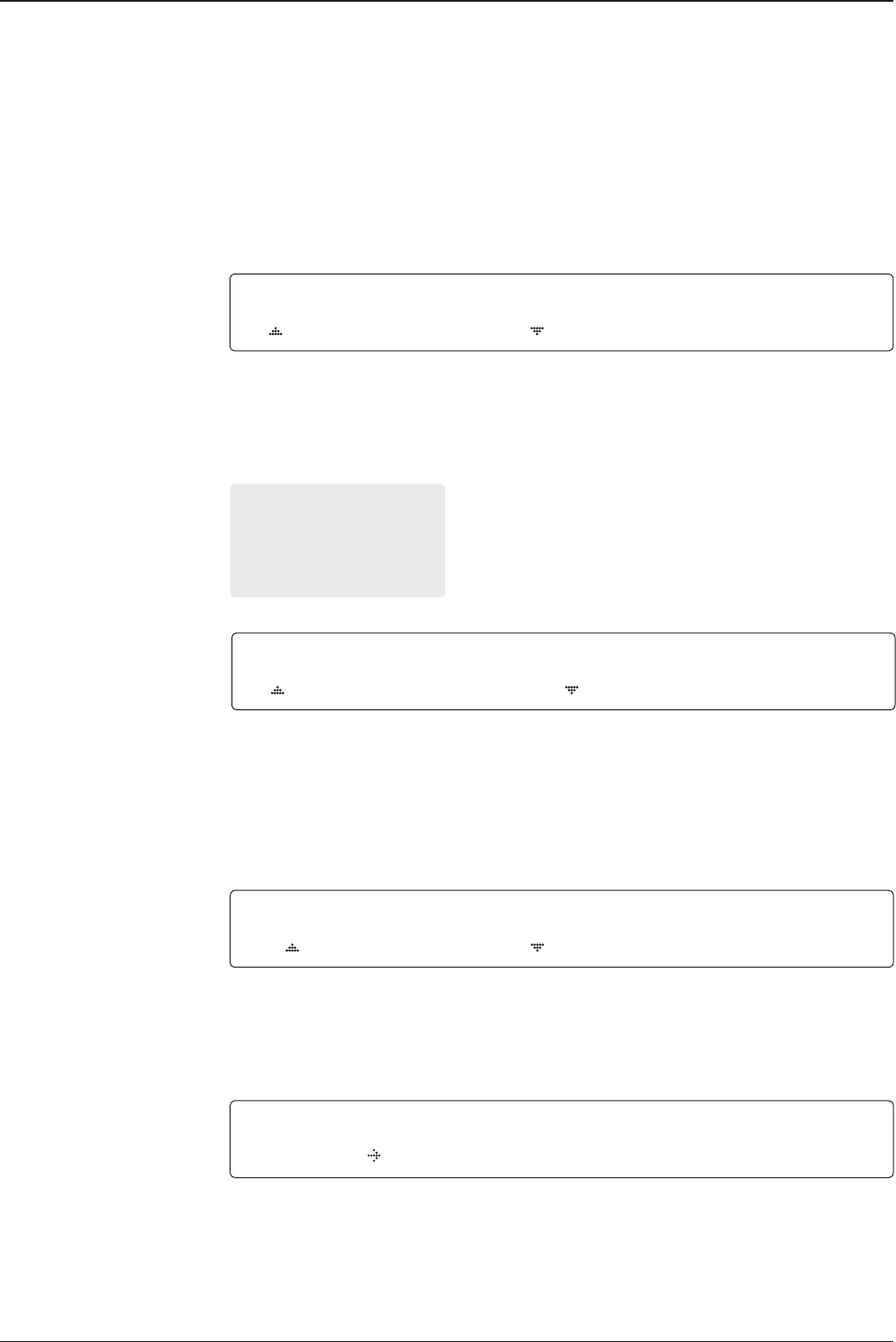
v240C – Marine Satellite Communication System
98
6. GPS OUT SENTENCE* is to select the GPS OUT SENTENCE type. USE TX MUTE is to
select whether or not to use the USE TX MUTE function from the satellite Modem. A transmit
inhibit output from the ACU will disable/mute the Modem transmit via a voltage whenever the
antenna is blocked, searching, or is mis-pointed 0.5 degrees from the peak satellite position.
Use TX mute
GPS OUT SENTENCE*
• GPGLL
• GPGGA
• SIMPLE GPGGA
TX mute activation
Save
TX MUTE ACTIVE
LOW
8. TX MUTE ACTIVE is a transmit inhibit output from the ACU to disable/mute the Modem
transmit through a 5 V (HIGH) or 0 V (LOW) current whenever the antenna is blocked,
searching, or is mis-pointed 0.5º from peak satellite position. TX MUTE ACTIVE item will only be
activated when PROTOCOL is set as I/O CONSOLE.
SAVE ?
YES NO
Use EXT.LOCK USE EXT.LOCK EXT. LOCK ACTIVE
YES LOW
7. USE EXT. LOCK is to select whether or not to use an external lock signal from the satellite
Modem. USE EXT. LOCK item will only be activated when PROTOCOL is set as I/O CONSOLE.
EXT. LOCK ACTIVE is referring that the Modem lock output from the Modem is providing a
logic input through a 5 V (HIGH) or 0 V (LOW). current to the ACU to identify when it is on
the correct satellite. EXT. LOCK ACTIVE item will only be activated when PROTOCOL is set as I/O
CONSOLE.
9. Press LEFT arrow key to move cursor to YES and press OK key to save current settings.
Or move cursor to NO and press OK key to abort and return to the main display.
G PS O UT SENTE NCE USE TX MUTE
GPGLL YES
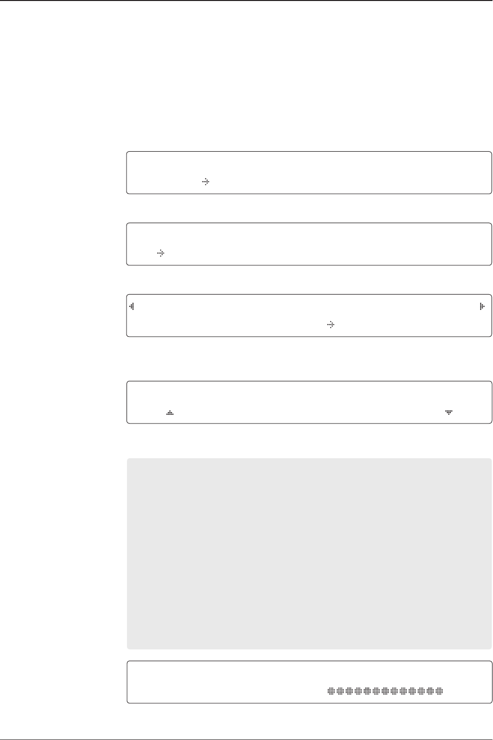
99
OPERATING THE ACU
System Management
System Menu
Management Menu
Setup Mode SETUP MODE ?
YES NO
1. Press LEFT arrow key to move cursor to YES and press OK key to enter SETUP Mode.
+ANTENNA +SATELLITE
+SYSTEM +INSTALLATION
2. Press DOWN arrow key to move cursor to SYSTEM menu and press OK key to enter it.
+SET LOCAL +SET LOCATION
+MODEM PORT +MANAGEMENT
3. Press arrow keys to move cursor to Management menu and press OK key to enter it.
Select process type SELECT PROCESS TYPE
BACKUP USER DATA
4. Press UP and DOWN arrow keys to SELECT PROCESS TYPE*
Press OK key to set the parameter and the processing message will be displayed.
SELECT PROCESS TYPE*
BACKUP USER DATA : To backup the antenna settings set by user.
RESTORE USER DATA: To restore the antenna by using the backup user data.
UPGRADE FROM USB : Upgrade the antenna by using FPW le stored at the USB.
COPY LOG TO USB : Copy log data from the antenna to the USB.
BACKUP TO USB : To backup the antenna settings set by user to USB.
RESTORE FROM USB : To restore the antenna by using the backup user data From USB.
UPGRADE ACU-REMOTE : Upgrade iARM by using TGZ le stored at the USB.
UPGRADE FROM USB / COPY LOG TO USB / BACKUP TO USB / RESTORE FROM USB /
UPGRADE ACU-REMOTE : These items are shown only when the USB memory stick is connected
at the ACU.
BACK UP ANT INFO
DO NOT TURN OFF!
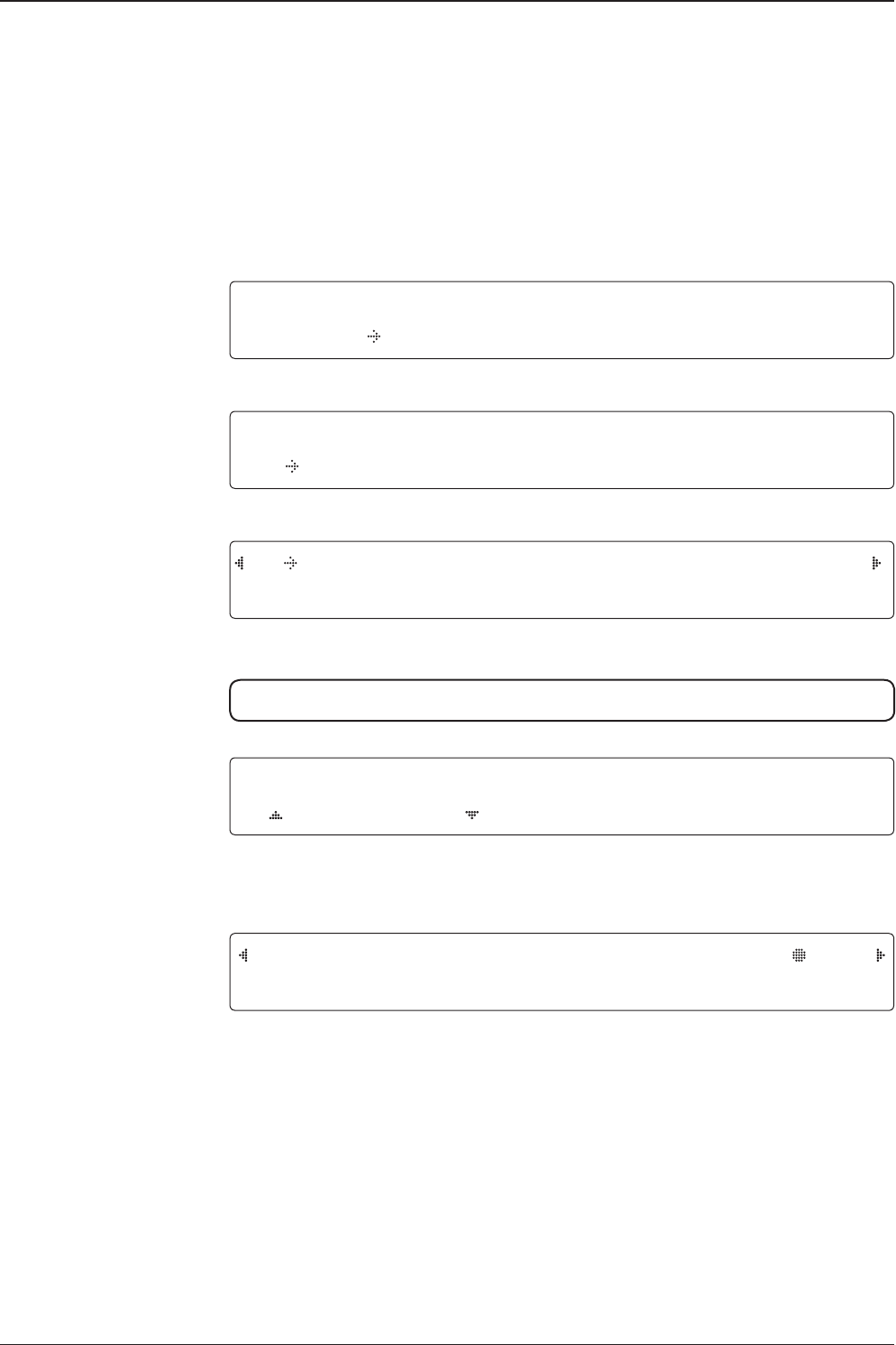
v240C – Marine Satellite Communication System
100
Key Lock
System Menu
Set key lock and
password
Key lock Menu
Setup Mode SETUP MODE ?
YES NO
1. Press LEFT arrow key to move cursor to YES and press OK key to enter SETUP Mode.
+ANTENNA +SATELLITE
+SYSTEM +INSTALLATION
2. Press DOWN arrow key to move cursor to SYSTEM Menu and press OK key to enter it.
+KEY LOCK + INTELLIAN DEVICE
3. Press arrow keys to move cursor to KEY LOCK menu and press OK key to enter it.
NOTE: INTELLIAN DEVICE menu is not operated in this ACU.
KEY LOCK UNLOCK P/W
ON 1590
4. Press UP and DOWN arrow keys to choose whether or not to use key pad lock when
entering the SETUP MENU or saving the satellite information. Setup the password for
entering the key pad lock. The factory default is 1590.
TRACKING 125.0E ASIA6H SIG:201
*AZ:181.7( 181.7) EL: 47.3 SK: 02.0 Fn
When KEY LOCK function is activated, the " * "mark is displayed.
Check key lock
activation

101
OPERATING THE ACU
Aptus®
Introduction to Aptus®
Requirements
Software Installation
PC to ACU Communication Setup
Starting Aptus®
Establishing a data communication
Toolbar Menus
System Property Status Dashboard
Work View Tabs
Antenna - Basic Info.
Antenna - Advanced Info.
Satellite
Graph View
Monitor
Diagnostic/Modem
GUI
Work View Functions

v240C – Marine Satellite Communication System
102
Intellian’s new VSAT Antenna PC Controller Software, Aptus® is a next-generation
graphically based antenna remote control software. The Aptus® allows users to
easily and conveniently set up the antenna by using a personal computer.
The minimum PC hardware and software requirements to install and run Aptus® are
as below.
Hardware
Hardware Requirements
CPU Intel® Pentium® 4 or higher
Memory 512MB or higher
Video Card
DirectX9.0 or higher supported
H/W acceleration supported
Video Memory 128MB or higher
HDD 1GB or higher
Operating System and Software
Software Requirements
Operating System Windows XP SP or higher
Framework Microsoft.Net Framework 3.5 Service Pack 1 or higher
Introduction to Aptus®
Requirements
103
Aptus®
Software Installation
Double click the ‘Aptus Setup.exe’ icon to install Aptus® directly onto your
computer/ laptop. The InstallShield Wizard will guide you through the program
setup process. The installation routine provides an icon on the desktop.
Click the icon to start the software. In addition, Intellian also provides patch les
for software upgrade.
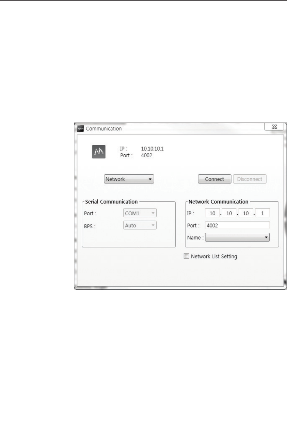
v240C – Marine Satellite Communication System
104
PC to ACU Communication Setup
Starting Aptus®
Double-click the Aptus® desktop icon, then Communication Window appears
to establish the data communication between your PC and the ACU. Select
options of connection method to access your ACU either through the Serial Port
Communication or the Network Communication (TCP/IP).
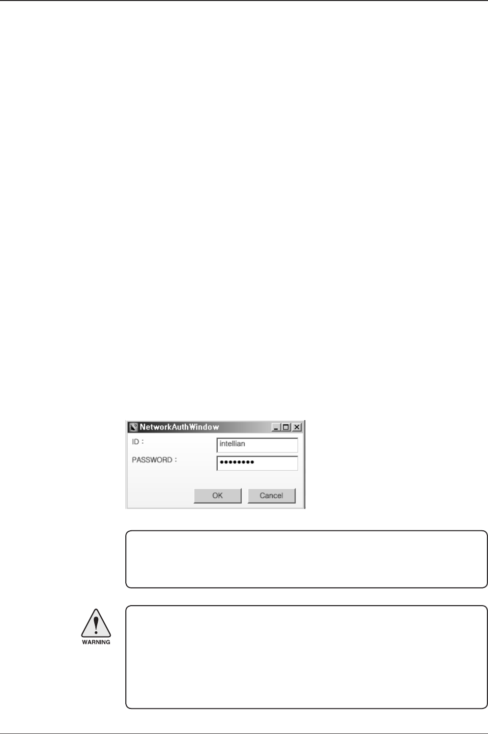
105
Aptus®
Establish a data
communication
Access ACU through Serial Communication
1. Connect a 9 pin Serial cable between the PC INTERFACE connector on
the ACU and the 9 pin Serial port on the PC. (Or you can use a USB cable
to setup Serial connection between a PC and the USB port on the ACU.)
2. Select Serial at communication type combo-box.
3. The baud rate of the ACU is 57600.
4. Select a COM port which is not occupied by other devices.
5. Click the Connect button.
Access ACU through Network Communication (TCP/IP)
1. Turn off the wireless connection while using this method.
2. Connect your PC to the Management Port.
3. Select Network at communication type combo-box.
4. Enter in the ACU’s IP address (Factory default : 192.168.2.1)
5. Enter in the ACU’s port number (Factory default : 4002)
6. Click the Connect button then the Authentication window will appear.
7. Login by using the username and password below:
- Username: intellian (Factory default)
- Password: 12345678 (Factory default)
WARNING:
- Do not plug a USB to the ACU while TCP/IP communication is in use.
Doing so will disable current PC Software Control because the USB
connection has higher priority than TCP/IP connection.
- The amount of data will increase rapidly if Network Communication is in use.
Intellian recommends using Aptus Web.
NOTE: If the remote access PC is located in the same network group with the ACU,
the ACU can be accessed through the internal IP address. But, if the remote access
PC is located outside of the network group, the ACU’s IP address should be changed
to the IP address assigned by the network service provider.
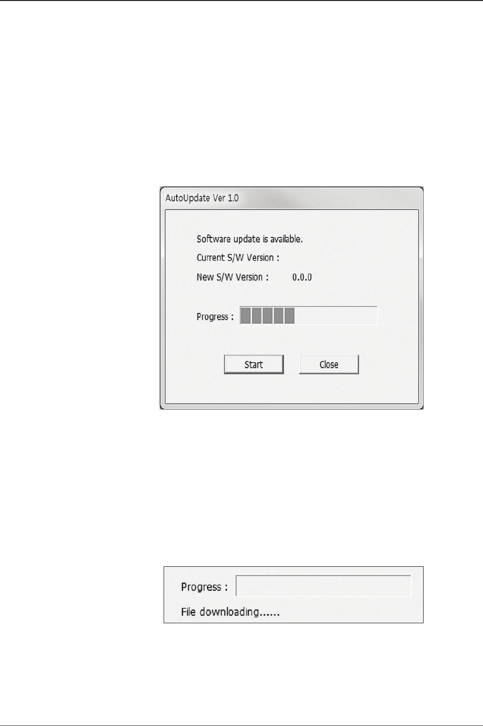
v240C – Marine Satellite Communication System
106
AutoUpdate
Intellian Aptus® checks and noties the latest version when it is started to maintain
up to date software version by AutoUpdate function.
1. When Aptus® is started, it automatically checks the latest software version from
the server and runs AutoUpdate if new version is available.
2. Current software version information is displayed.
3. It noties new software version information.
4. When you click the “start” button, “File downloading…” message is displayed
while downloading les from the server.
5. When le downloading is nished, “installing…” message is displayed and Aptus
patch runs and the installation starts by InstallShield.
6.Click the “Finish” button when InstallShield installation is nished, then “Run
the Aptus” message is displayed and Aptus runs and AutoUpdate is automatically
nished.
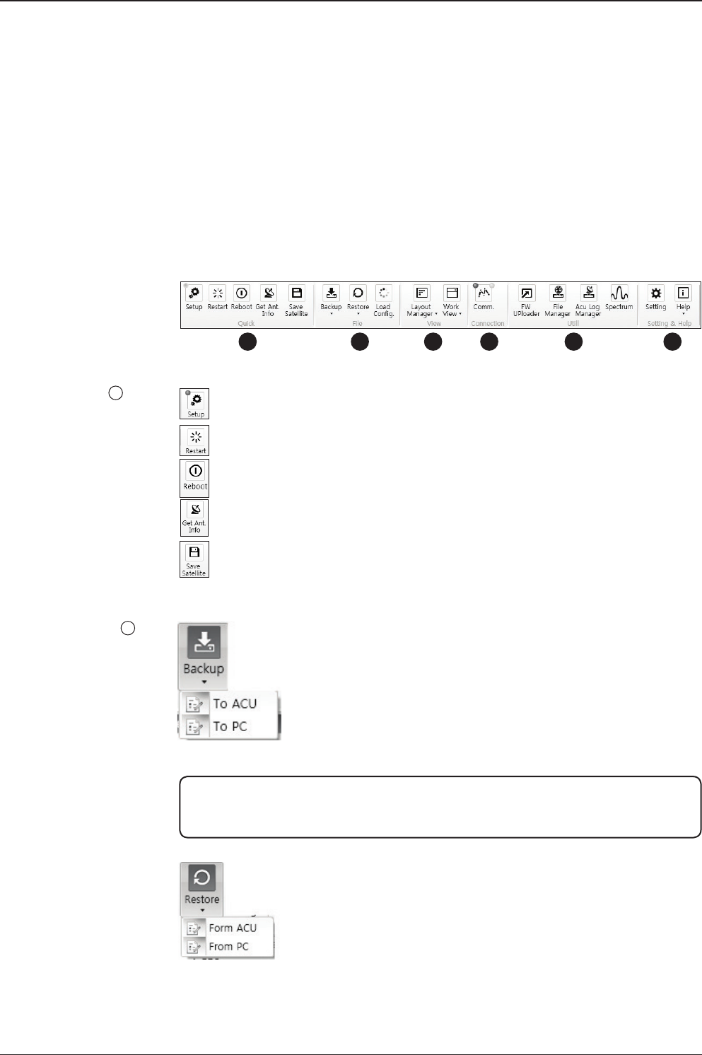
107
Aptus®
Quick
File
Toolbar Menus
The toolbar menus at the top of the screen display command buttons of the most
commonly used functions of the Aptus®. The toolbar menus consists of 4 main
menus; Quick (for quick launch of functions), File (for le backup, restoring and
loading), View and Connection.
Setup: enters Setup MENU.
Restart: exits Setup MENU and restarts the antenna.
Reboot: reboots the antenna.
Get Ant. Info: obtains the information stored in the antenna
Save Satellite: saves the current bow offset only if the antenna is tracking
onto the satellite. The satellite acquisition time can be reduced signicantly
after the antenna is restarted.
1
1
2
23 4 5 6
Backup: Backups the antenna information to ACU or PC.
- Select ‘To ACU’ to backup the antenna information to ACU.
The backup le (le format: *.ibf) will be stored on the ACU.
- Select ‘To PC’ to backup the antenna information to a PC.
The backup les (le format: *.rpt and *.ibf) will be generated
on the PC.
Restore: restores the antenna by using the stored information in
ACU or PC.
- Select ‘From ACU’ to restore the antenna by using the stored
information in ACU.
- Select ‘From PC’ to restore the antenna by using the stored
information in PC (le format: *.ibf).
NOTE: Both *.rpt and *.ibf les contain antenna information. However, while *.ibf le can
be used for restoring antenna information, *.rpt le is stored as plain-text for viewing
purpose only. Users can open the *.rpt using text editors such as notepad software.
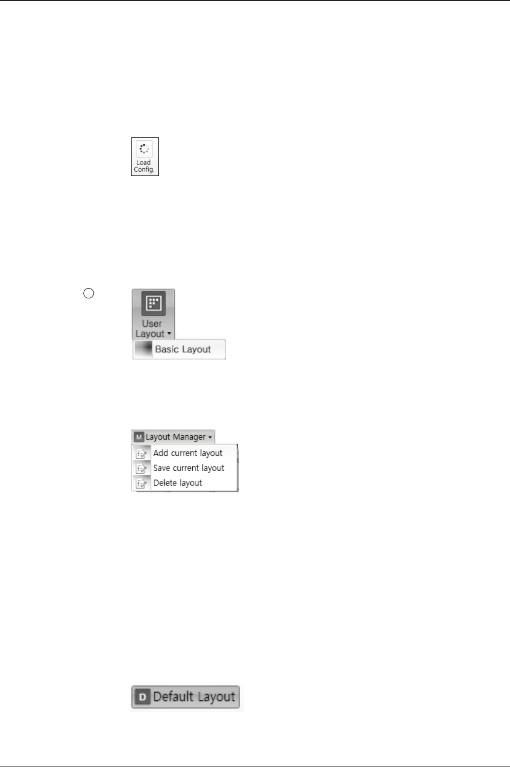
v240C – Marine Satellite Communication System
108
View
3
• User Layout: displays the layout list that the user has previously stored by using
Layout Manager. If you select a layout in this list, the selected layout will be
constructed in Work View screen. The ‘Basic layout’ is provided by default.
• Layout Manager: provides the user with add, delete, and save functionalities in
order to manage the user’s layouts.
- Selecting ‘Add current layout’ opens a pop up window. Type in a desired name
of current layout and click Add, then the new name of the current layout will be
saved to the list under User Layout menu.
- When changes are made to the current layout, select ‘Save current layout’ option.
The current layout will be saved with changes.
- To remove a layout, select ‘Delete layout’ option. Select a desired layout to remove
on the pop up window, then click ‘Delete’. Close the window by clicking on ‘Close’.
The selected layout is removed from the User Layout list.
• Default Layout: returns the current layout to the default layout.
Load Cong. : loads the antenna conguration le (le format: *.cfg).
The conguration le includes the antenna control parameters which are
pre-loaded at the factory and should only be changed by an authorized service
technician. Improper setting of these parameters will cause your system to
perform improperly.
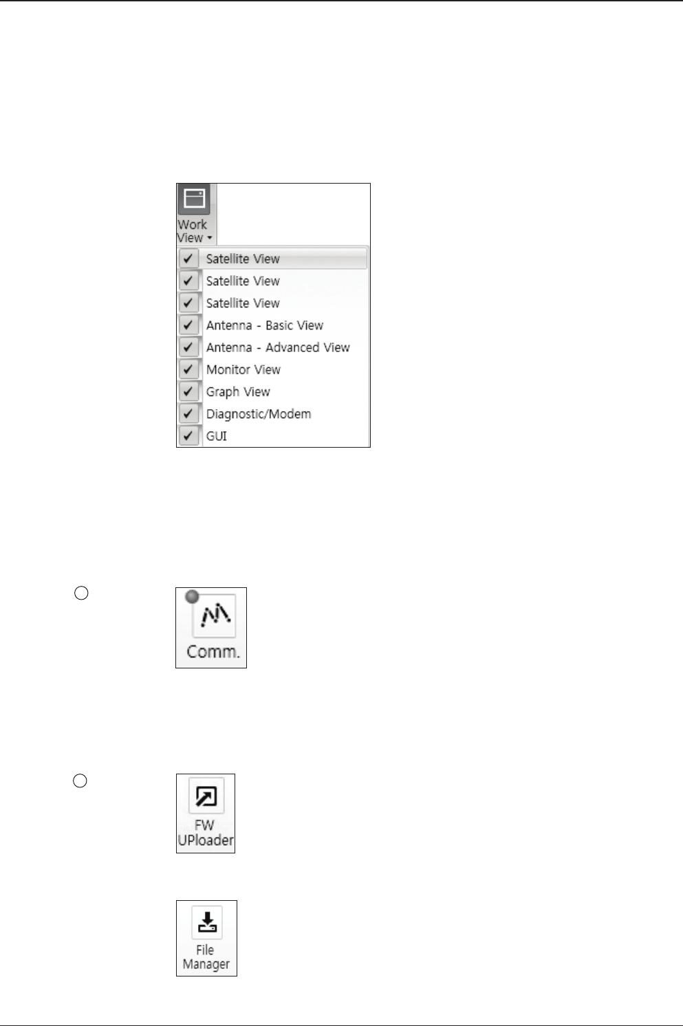
109
Aptus®
Connection
4
• Work View: displays a list of seven pre-constructed Work View Tabs (Satellite
View, Antenna Basic View, Antenna Advanced View, Monitor View, Graph View,
Diagnostic/Modem View and GUI View and also provides the Activate / Close
functionalities for each view tab. Activate the work view tab by ticking the
checkbox next to it.
At any time, data communication channel can be re-established between Serial
and Network connection. Selecting Comm. Button will display Communication
Window to connect to the ACU via Serial or Network communication.
Utill
5
• Firmware Uploader: provides the user with the latest rmware version and
updates rmware by simple steps.
• File Manager: display the latest rmware and library le available on Aptus Server.
Select a desired rmware and download to the local PC.
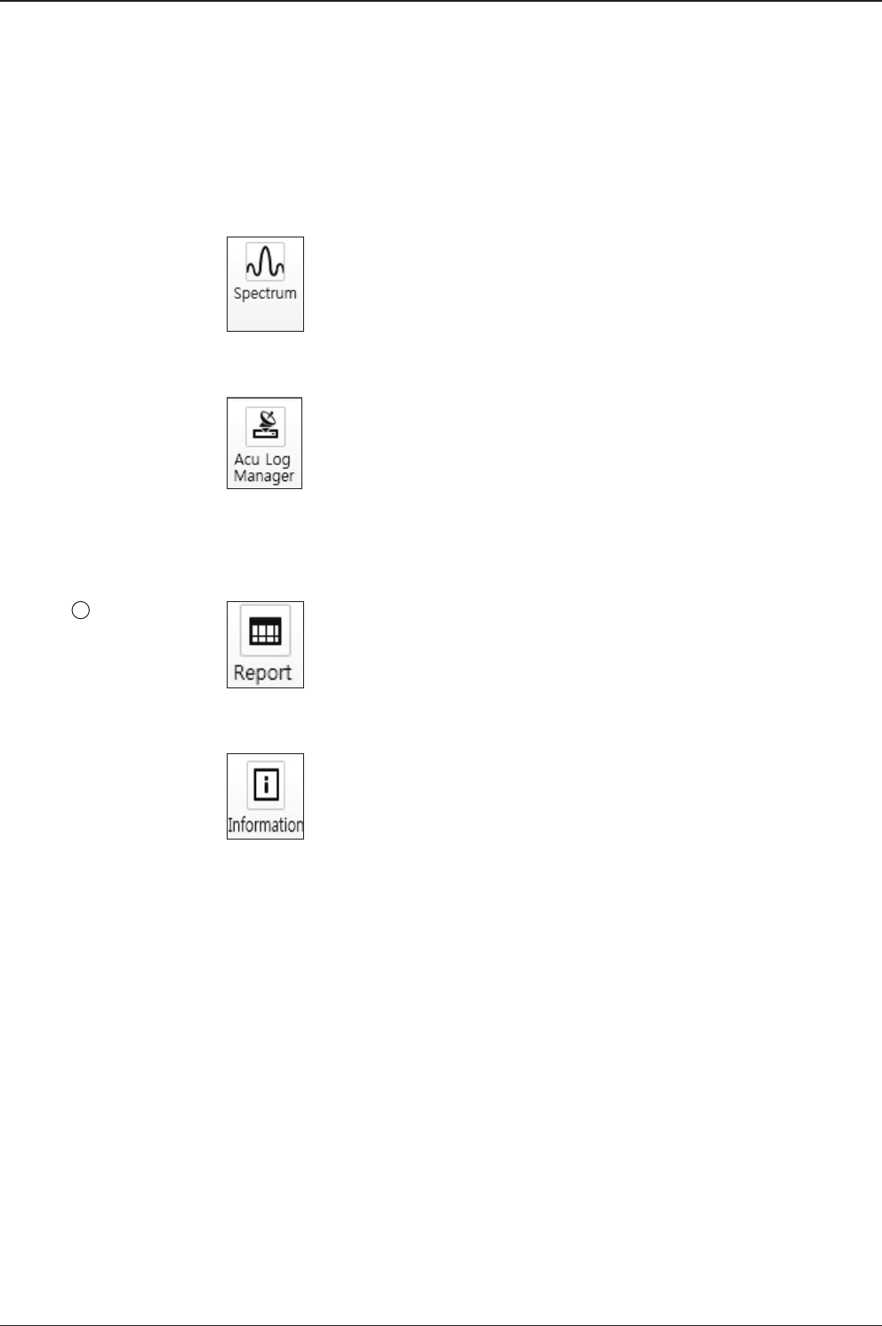
v240C – Marine Satellite Communication System
110
• Spectrum: displays current spectrum graph and allows to set spectrum data view
options.
• ACU Log Manager: displays the antenna log data in calendar view which is
downloadable directly to a desired path.
Setting & Help
6
• Report: provides e-mail contact to Intellian technical support team to let the user
report problems at any time.
• Information: displays the information of current Aptus® software version.
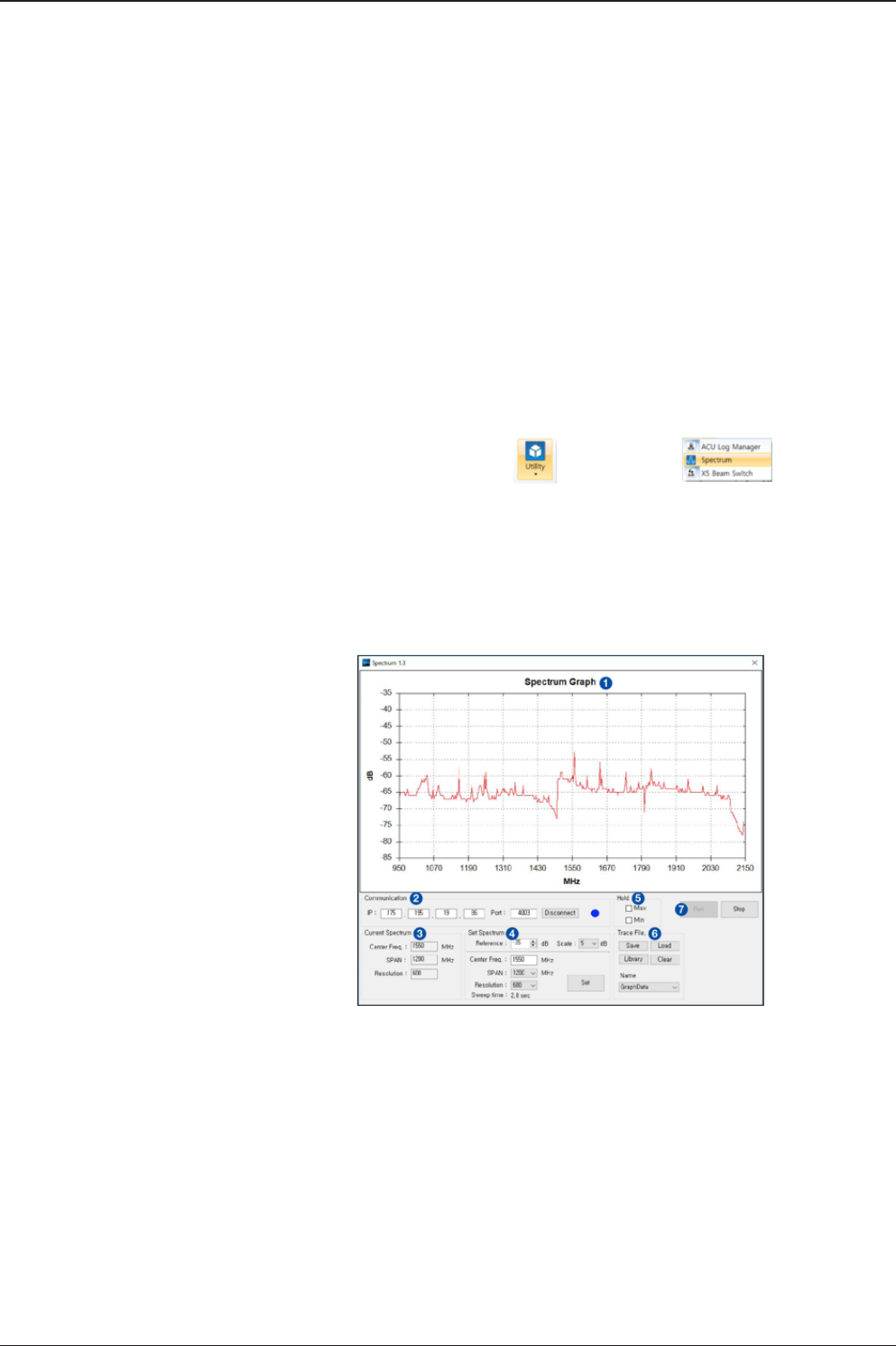
111
Aptus®
Spectrum Analyzer Main Menu
1) Graph
Displays measurement results. The display of a spectrum analyzer has the
frequency on the horizontal axis and the amplitude displayed on the vertical
axis.
2) Communication
Access the Spectrum Analyzer entering the ACU’s IP address and Port
number. Then click the Connect button. When Aptus has connected Ethernet,
Spectrum Analyzer will connect automatically.
The connection status is displayed on the right LEDs. The blue is in connection
status and the gray is disconnection status.
How to set up Spectrum Analyzer
1. Spectrum Analyzer Function
• Display that a spectrum analyzer measures an input Rx signal frequency within
the full frequency range and sets spectrum data view.
• The disconnect fault can be checked and solved through spectrum analyzer
results.
2. Access Spectrum Analyzer
On the Aptus PC, select “Utility ( ) è Spectrum ( )”on the toolbar
menus to display current spectrum graph and allow to set spectrum data view
options.
3. Spectrum Graph / Data View
After clicking the Spectrum menu button, the spectrum analyzer will be popped
up. To perform the Spectrum Analyzer function, check the following information.

v240C – Marine Satellite Communication System
112
3) Current Spectrum
Display the current Spectrum settings.
4) Set Spectrum
• Reference/Scale: Set Amplitude Reference Level and Scale. Press the
Reference Level submenu key and use the arrow keys, or the keypad to
change the reference level (2000 to -2000). Select the Scale number (1, 2, 5,
or 10 dB) in the drop down list to enter the desired scale.
• Center Freq.: Enter the desired center frequency using the keypad then click
the Set button to apply the adjusted value. The adjusted value is shown at
the Current Spectrum part.
• Span: To quickly move the span value up or down, select the span number
(6, 60, 300, or 1200 MHz) in drop down list. These numbers facilitate a
zoom-in, zoom-out feature. Then click the Set button to apply the adjusted
value. The adjusted value is shown at the Current Spectrum part.
• Resolution: To quickly adjust the resolution value up or down, select the
resolution number (100, 200, 300, or 600) in drop down list. These numbers
facilitate a zoom-in, zoom-out feature. Then click the Set button to apply the
adjusted value. The adjusted value is shown at the Current Spectrum part.
• Sweep Time: Display the elapsed time all data received during the start to
sop testing interval.
5) Hold
• Max: Set the desired maximum display range value by clicking the check
button. Then click the Set button to change the max level.
• Min: Set the desired minimum display range value by clicking the check
button. Then click the Set button to change the min level.
6) Trace File
• Save: Save current Spectrum setting values and data.
• Load: Load the Trace le and display the data on the spectrum graph.
• Library: Create the new Trace le. After saving the le, it will show in the
Name list.
• Clear: Remove the spectrum data displayed on the graph.
• Name: Show the Trace le which it was created at Library in the drop down
list.
7) Run/Stop
• Run: Request the spectrum data to antenna continuously and update graph
data in real time.
• Stop: Stop requesting the spectrum data. (The graph cannot be updated.)

113
Aptus®
4. Change Zoom in Spectrum Graph (Example)
For example, 1550 MHz is the default frequency in the spectrum graph. If you
wish to base the spectrum graph on 1824 MHz, follow these steps:
1. Adjust Center Freq. to the desired value. (e.g. 1824 MHz)
2. Adjust Span value to the desired value. (e.g. 300 MHz)
3. Adjust Resolution to the desired value. (e.g. 300)
4. Click the Set button to apply the adjusted values. Verify the spectrum graph is
now displayed using the desired values.
Spectrum Analyzer Graph using defaults
Zoom in Spectrum Analyzer Graph
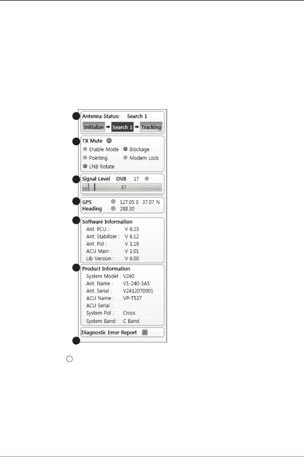
v240C – Marine Satellite Communication System
114
System Property Status Dashboard
The property status dashboard on the left pane of the screen provides the antenna
status, the availability of TX transmission, signal level, GPS and heading status,
software information, product information and error status to be monitored quickly.
Antenna Status: Displays the status of the current MENU of the antenna.
- Search 1: A Search 1 pattern will automatically be initiated when the ship’s
heading input does not exist or if it fails. The search cycle will repeat until the
antenna receives the lock signal from the Modem or until the DVB transponder
of the target satellite is decoded by the antenna.
- Search 2: Search 2 is reserved for future use.
- Search 3: Search 3 pattern will automatically be initiated when AGC(NBD menu
is in use) or SIG(DVB menu is in use) falls below the current tracking level
threshold value. Once the desired signal is found and above the predened
tracking threshold, the ACU will enter to tracking menu.
1
1
2
3
4
5
6
7

115
Aptus®
- Tracking: Antenna is tracking the target satellite.
- Initialize: Antenna or ACU is initializing.
- Setup: Antenna is in SETUP mode.
TX Enable
Displays the status of TX transmit. If the circle next to the TX Enable shows “Blue”,
it means the antenna TX function is enabled. If the circle shows “Red”, it means
the antenna TX function is disabled. The TX function will be enabled only if all ve
factors (Enable Mode, Blockage, Pointing, Modem Lock, and LNB Rotate) listed
below show a “Blue” circle. However, if the “Use TX Mute” function in the ‘ACU
System’ Work Tab is disabled, the TX function will be enabled regardless the above
factors.
- Enable Mode: displays whether or not the antenna istransmitting.
- Blockage: displays whether or not the antenna is pointing in a predened
blockage zone(s). If the antenna is pointing in the blockage zone, the circle next to
the Blockage will show “Gray”. If the antenna pointed outside the blockage zone,
the circle next to the Blockage will show “Blue”.
- Pointing: displays whether or not the antenna is pointing to the target satellite. If
the antenna is mis-pointing to the target satellite, the circle next to the Pointing will
show “Gray”. If the antenna is pointing to the target satellite, the circle next to the
Pointing will show “Blue”.
- Modem Lock: displays whether or not the modem is locked by receiving a
conrmation signal from the satellite modem. If the modem is not locked, the circle
next to the Modem Lock will show “Gray”. If the modem is locked, the circle next to
the Modem Lock will show “Blue”.
NOTE: If the Modem Lock shows “Gray”, check the cable connection between
the antenna system and the satellite modem as well as settings on the modem.
- LNB Rotate: displays whether or not the LNB is rotating. If the LNB is rotating, the
circle next to the LNB Rotate will show “Gray”. If the LNB is not rotating, the circle
next to the LNB Rotate will show “Blue”.
2
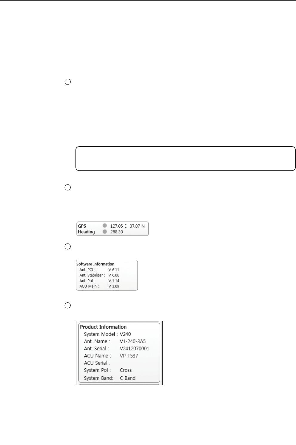
v240C – Marine Satellite Communication System
116
Signal Level
Shows “DVB” when DVB MENU of tracking signal is in use and “NBD” when NBD
mode of tracking signal is in use. The “Red” line indicates the signal “Detect Level
Threshold” and the “Orange” line indicates the signal “Tracking Level Threshold”.
If the signal level is higher than the tracking level threshold, the signal level bar will
display “Blue” color. If the signal level is lower than the tracking level threshold, the
signal level bar will display “Orange” color and the antenna will stay in searching
mode.
NOTE: If the signal level is not higher than the tracking threshold, decrease the detect
and tracking level.
GPS and Heading
Displays the current GPS location from the Antenna and Ship’s heading information.
The status light ashes green if the system receives a correct input of the GPS and
Ship’s heading.
Software Information: Displays the antenna and the ACU rmware versions, and the
library version.
Product Information: Displays the antenna and ACU serial numbers, antenna MENUl
and ACU model.
3
4
5
6
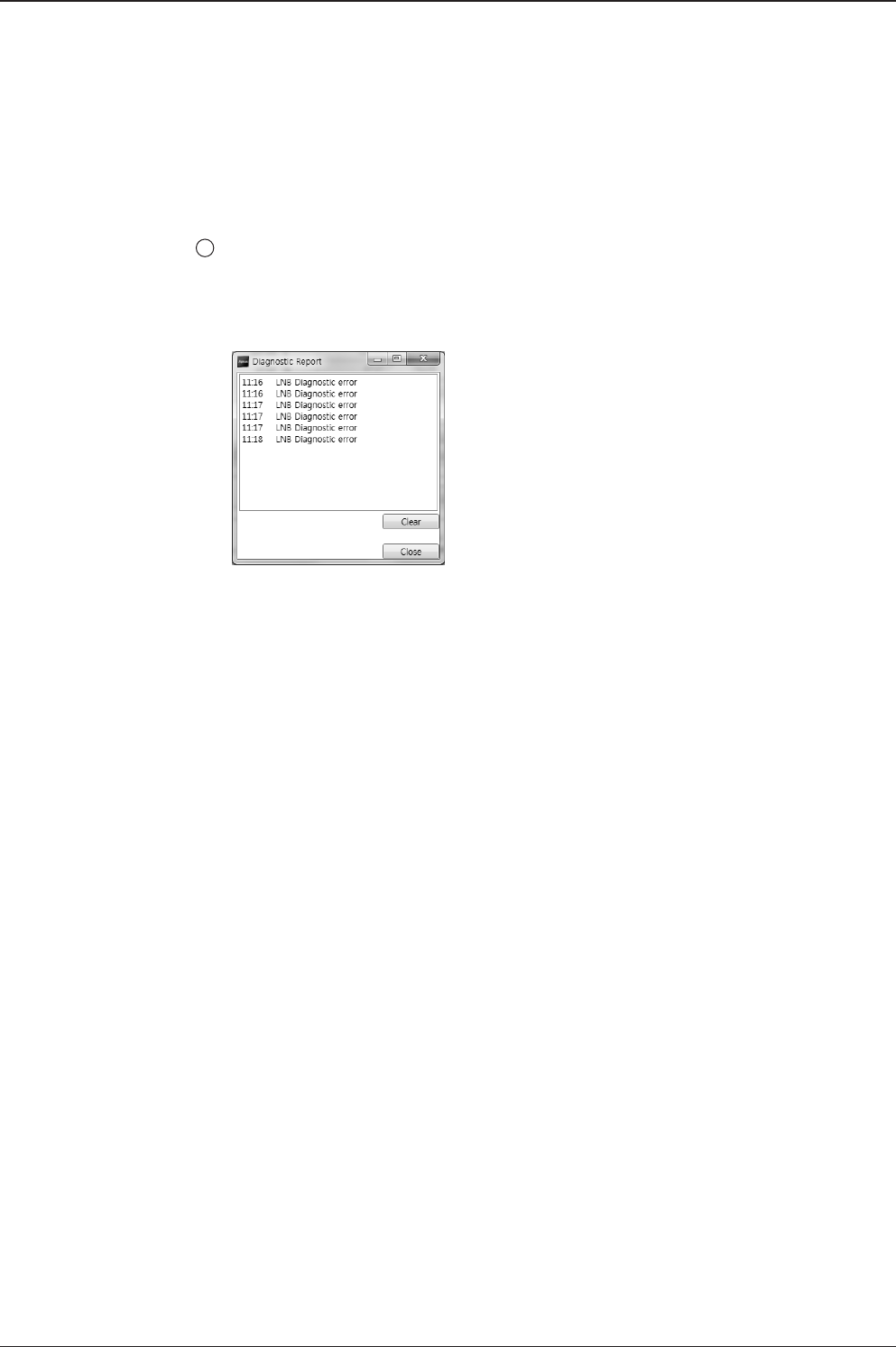
117
OPERATING THE ACU
Diagnostic Error Report
The square button next to the Diagnostic Error Report turns red when the system
receives an error. Click the button to see a Diagnostic Report.
7
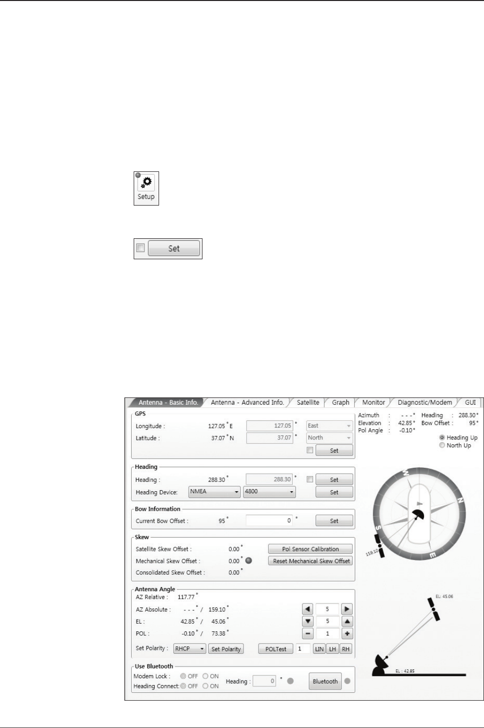
v240C – Marine Satellite Communication System
118
Work View Tabs
Aptus® provides seven Work View Tabs (Satellite View, Antenna Basic View,
Antenna Advanced View, Monitor View, Graph View, Diagnostic/Modem and GUI)
to manage the Antenna and the Satellite conguration.
How to modify the settings on Work View;
1. Enter the Setup MENU by clicking Setup icon.
2. Tick the checkbox next to the “Set” button to modify the settings.
3. Enter the desired value then press the Set button to save the settings.
1. Antenna – Basic Info.
This view tab provides information on the Antenna’s Current GPS location, Head-
ing Device, Bow Information, Skew Information, and the Antenna’s Angle. This
view tab uses the Antenna’s AZ and EL information as well as the Ship’s Heading
information in order to provide a dynamic graphic user interface (UI).

119
Aptus®
- GPS: displays and sets current antenna’s GPS.
- Heading: displays and sets current ship’s heading information.
· Heading Device: None / NMEA/ NMEA 2000/Ground Test.
The baud rate (4800/ 9600/ 19200/ 38400) must be set if NMEA is selected.
- Bow Information: displays and sets current antenna’s bow.
- Skew: displays current antenna’s skew and skew offset.
· Pol Sensor Calibration: calibrates the sensor (potentiometer).
· Reset Mechanical Skew Offset: the mechanical skew offset is preset in
the factory with a default value (0, 1, or 2) depending on the assembly
status. Resetting of the mechanical skew offset may be required when
the satellite skew offset is unknown Consolidated Skew Offset=
satellite skew offset + mechanical skew offset). Due to each satellite has
its own skew offset, Intellian recommends you check with your service
provider or satellite operator to get the satellite skew offset value and
input it in Satellite Work Tab rather than resetting the mechanical skew
offset directly.
- Antenna Angle: displays and sets current antenna’s absolute and relative AZ
(azimuth) position, EL (elevation) position and LNB Pol angle. You can move
antenna azimuth and elevation position and LNB Pol angle by using the arrows or
inputting a value to nd the desired satellite manually.
- Use Bluetooth: The data communication between the ACU and the antenna will
be terminated once the Bluetooth function is activated. The built-in Bluetooth
connection module inside of the antenna dome can enable a PC connection right
alongside the dome.
· Modem Lock: turns on/off the Modem lock signal sent from your PC/
laptop to the antenna while Bluetooth is in use.
· Heading Connect: turns on/off the heading signal sent from your PC/
laptop to the antenna while Bluetooth is in use.
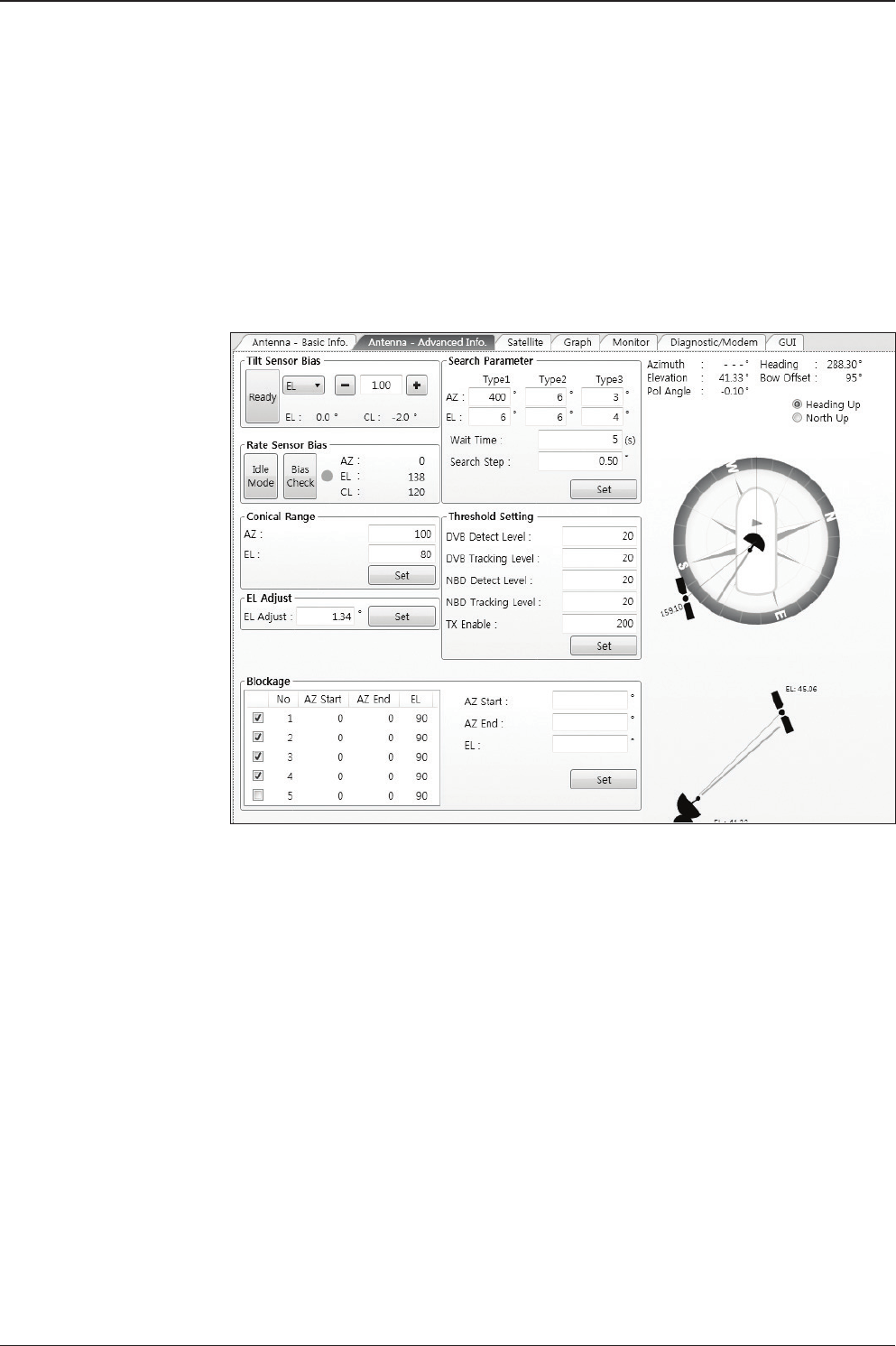
v240C – Marine Satellite Communication System
120
2. Antenna – Advanced Info.
This view provides information on the Tilt Sensor Bias, Conical Range, EL Adjust,
Rate Sensor, Search Parameter and Blockage Zone.
-Tilt Sensor Bias: This maintains the elevation and the cross level axes
in order to keep the pedestal parallel to the horizon. Adjust the two solid-
state tilt sensors to provide absolute cross-level tilt of the antenna and el
evation feedback to eliminate long-term pointing drift (error). Tilt bias
must be adjusted when the antenna control board or sensor box is
replaced. If the bubble on the button level located on the sensor box is
not centered, follow the following steps to adjust the tilt sensor bias.
· Step 1. Enter Setup MENU and press the “Ready” button to bring
the elevation and cross-level to 0.
· Step 2. Select “EL” from the drop down list and press Up and
Down arrow keys to adjust the bubble until it is located in the
center ring of the button level.
· Step 3. Select “CL” from the drop down list and press Up and
Down arrow keys to adjust the bubble until it is located in the
center ring of the button level.

121
Aptus®
· Step 4. Press the “Restart” icon to restart the antenna.
- Rate Sensor: is used to calibrate the DC voltage output from the three rate sen-
sors (azimuth, elevation, and cross-level). These are used to sense antenna motion
that corresponds to the ship’s motion (roll, pitch, and yaw) for stabilizing the ped-
estal. The DC voltage output from each of the rate sensors may vary by an amount
which is directly proportional to the direction and rate of motion induced on it.
Before calibrating the rate sensors located in the Sensor box, make sure that the
antenna is placed on a rigid and at platform. During the calibration process, any
motion of the antenna should be avoided as it can affect the antenna’s perfor-
mance. Proceed with the following steps to perform the calibration.
· Step 1. Enter Setup MENU
· Step 2. Press the “Idle MENU” button to release the elevation and
cross level motor brakes while the antenna is in Setup MENU.
· Step 3. Check whether or not the bubble is located at the center
of the button level. If not, move it to the center by following the
previous instruction of Tilt Sensor Bias adjustment.
· Step 4. Press the “Bias Check” button to calibrate the rate sensor.
A blue circle will be displayed next to the Bias Check button if the
calibration is completed. A red circle will be displayed if calibration
failed. A green circle will be displayed during the calibration
process.
- Conical Range: The relative force of the motors controlling azimuth and eleva-
tion. Set the conical range while the antenna is in tracking MENU.
- EL Adjust: The elevation adjustment is to offset the angle difference between the
mechanical elevation angle and actual elevation angle. If this value is not properly
adjusted, the antenna may take longer time for satellite search or tracking.
- Search Parameter:
· Wait time: set the time-out for automatic initiation of a search after
the signal level drops below the pre-dened threshold value.

v240C – Marine Satellite Communication System
122
· Search Step: set increment step size.
· Type 1 & Type 3 (Search 1 & 3) Range: set Search 1 & 3 search
range. Search 3 is conducted in a two-axis pattern consisting of
alternate movements in azimuth and elevation as it forms an
expanding square.
· Type 2 (Search 2) Range: is reserved for future use.
- Blockage Zone
Displays current blockage zones by azimuth and elevation sectors. Up to 5 block-
age zones can be programmed. Once the blockage zone is created, a blue shad-
ing area will be displayed in the Antenna UI view on the right.
- Threshold Settings
· DVB Detect Level: displays and sets signal detection threshold
level when DVB tracking MENU is in use.
· DVB Tracking Level: displays and sets signal tracking threshold
level when DVB tracking MENU is in use.
· NBD Detect Level: displays and sets signal detection threshold
level when NBD tracking MENU is in use.
· NBD Tracking Level: displays and sets signal tracking threshold
level when NBD tracking MENU is in use.
· TX Enable Threshold: displays and sets TX enable threshold.
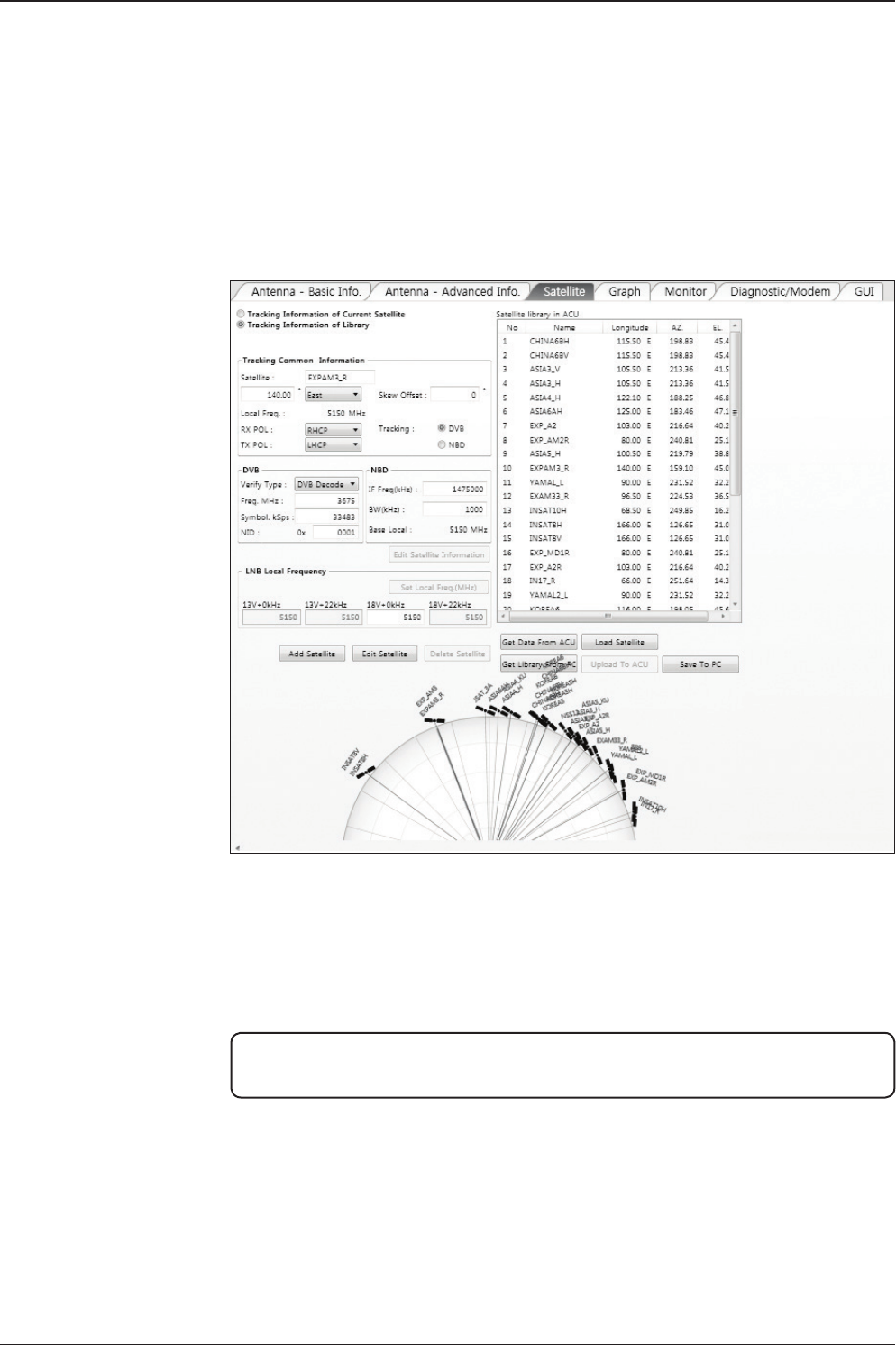
123
Aptus®
3. Satellite
This view provides information on the Satellite’s Information, Tracking Common
Information, DVB and NBD Tracking Transponder, LNB Local Frequency, and Sat-
ellite Library. This view shows a graphic UI of the current satellite that the antenna
is pointing at and the satellites that are located at a 180° arc on the horizon with
reference to the current position.
NOTE: Based on the satellite EIRP footprint and the size of the antenna, you may not
be able to track all the satellites visible in 180° arc.
- Tracking Information of Current Satellite: displays the current satellite’s name,
longitude position, and satellite skew of the satellite in the library.
- Tracking Common Information: displays the current LNB local oscillator fre
quency that is in use and the corresponding voltage supplied. Selects the
tracking MENU (DVB / NBD) to be used and sets polarization (Horizontal / Verti
cal) for the RX pol and the TX pol.

v240C – Marine Satellite Communication System
124
- DVB / NBD: sets tracking transponder
information for either DVB tracking MENU (Verication Type, Frequency, Symbol
rate, and NID) or NBD tracking MENU (Frequency and bandwidth).
NOTE: DVB and NBD parameter settings should only be changed by an authorized
service technician. Improper setting of these parameters will render your system
inoperable. Consult Intellian for changing antenna parameters.
- LNB Local Frequency: Displays or sets LNB local frequency and its corre-
sponding LNB voltage supplied. You may select pre-programmed LNB LO settings
from the drop down list. This procedure is same for both the Intellian Global VSAT
PLL LNB and any other LNB.
- Tracking Information of Library: Selecting this option enables “Add Satellite”,
“Edit Satellite” and “Delete Satellite” buttons.
· Eutelsat: Select 'ON' when the antenna is tracking an Eutelsat satellite.
With this option enabled, a dened skew angle for each Eutelsat satellite
is automatically applied without allowing a manual modication to the
skew offset value.
· Get Library From PC : opens the satellite library le (File format:*.ilf)
from the PC.
· Get Data From ACU: obtains the satellite information from the ACU.
· Load Satellite: uploads the satellite information to the ACU.
· Upload to ACU: uploads the satellite library to ACU.
· Edit Satellite: edits the satellite information of the selected satellite.
· Add Satellite: adds the satellite information as dened in the current
settings.
· Delete Satellite: deletes the selected satellite from the library.
· Save to PC: saves the current library settings to PC.
NOTE: It is required to click the "Save to PC" button after "Edit Satellite", “Add Satellite",
or "Delete Satellite" button is clicked.
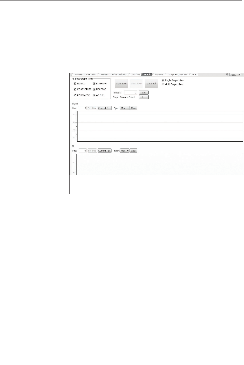
125
Aptus®
4. Graph View
This view provides information on Signal, Elevation (EL), Absolute AZ (Azimuth),
Relative AZ, Heading, AZ and EL in Single or Multi graph formats.
- Select Graph Item: shows the graphs of only the checked item(s) in a
Single or Multi Graph View.
- Single Graph View: shows Graph Views per each single Graph Item
selected in ‘Select Graph Item’.
- Multi Graph View: shows one large integrated Graph View of multiple
Graph Items selected in ‘Select Graph Item’.
- Start/Stop Save: the chosen item is saved within the data log. The data
log which stores the information displayed in the graphs can be later
used for a service technician to nd out a cause of any possible problem
to the antenna.
- Clear All: clears everything drawn on the Graph View window.
- Set Pos.: sets the current position as center value of each Graph Item.
- Current Pos.: moves to the location according to values of each Graph Item.
- Span: sets the Display Range(s) of each corresponding Graph Item.
- Period: displays and sets the signal sampling rate.
- Graph Column Count: makes all Graph Views show in either one or
two-column format.
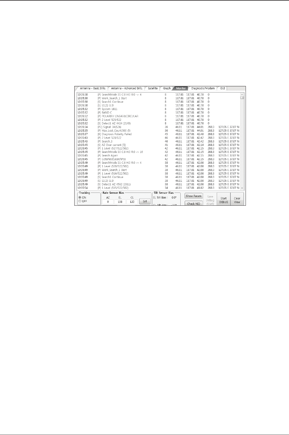
v240C – Marine Satellite Communication System
126
5. Monitor
This view provides a UI which can monitor all data that has been received from the
ACU.
- Tracking: turns on or off the dish scan function. If the dish scan function
is disabled, the antenna will stop adjusting the antenna pointing angle in
order to optimize the receive signal level.
- Rate Sensor Bias: is used to calibrate the DC voltage output from the
three rate sensors (azimuth, elevation, and cross-level). These are used
to sense antenna motion that corresponds to the ship’s motion ( roll,
pitch, and yaw) for stabilizing the pedestal. You can nd the same
function in Antenna-Advanced View Tab.
- Show Param: shows the current antenna parameters.
- Check NID: veries the NID (network ID) of the current tracking tran
sponder. Press the NID button to obtain the NID only if the antenna is
locked onto the desired satellite .
- Debug (Start): starts the debug log of the antenna. The debug message
will be displayed once the debug button is pressed.
- Stop Debug: stops debug logging of the antenna.
- Save Log (Start/Stop): starts or stops the logs of the antenna. This
button will be enabled while viewing the debug log. The log message
will be stopped or be saved into a *.txt le once the log button is pressed.
(V_Date.txt.)
- Save Debug (Start/Stop): starts or stops saving the debug log. This button is
enabled once the Start Debug button is pressed.
- Clear View: clears the debug message or log data in monitoring window.

127
Aptus®
6. Diagnostic / Modem
This view provides Antenna Diagnostic Testing and also provides functions to set
up the interface between the ACU and Intellian VSAT Mediator, Intellian Modem
Mediator or the satellite Modem.
- Diagnostic : select to run a full diagnostic test or single diagnostic test.
"Green" indicator is displayed for the test under progress. "Blue" indicates the
test result as Pass while "Red" indicates the result as Fail. "Yellow" indicates the
test has been skipped.
· Serial Comm.: tests the data communication between the antenna
and the ACU.
· Motor AZ: tests the azimuth motor.
· Motor EL: tests the elevation motor.
· Motor CL: tests the cross-level motor.
· Encoder AZ: tests the azimuth encoder.
· Encoder CL: tests the cross-level encoder.
· Rate sensor: tests the rate sensor.
· Tilt Sensor: tests the tilt sensor.
· Home sensor: tests the home sensor.
· ACU power: tests the ACU power to see whether or not it is
within the nominal operating range.

v240C – Marine Satellite Communication System
128
· Antenna power: tests the antenna power to see whether or not it
is within the nominal operating range.
· Skew: tests the LNB skew motor.
· LNB/ NBD: tests the LNB and NBD (narrow band detector).
· Sensor Box Limit: tests the sensor box motor .
- Modem: sets the interface between the ACU and Intellian VSAT Mediator,
Intellian Modem Mediator or the satellite modem.
NOTE: Before setting this function, make sure connection of a RJ45 cable from the
Ethernet connector on the ACU to the Modem or conect a 9 pin serial cable from
the RS232/422 connector on the ACU to the Modem.
· Use Mediator: enables use of the Intellian Dual VSAT Mediator.
Use Mediator must be set to “NO” if there is no MEDIATOR
connected to the ACU. Improper setting of this parameter will
cause your ACU’s Modem interface to work incorrectly.
· Select Modem: selects your Modem type for loading pre-conguration
settings. If the ABS (auto beam switching) function is in use, select
either IDIRECT-AMIP or COMTECH-ROSS depending on which
type of Modem is used.
· Modem Port: selects a proper data communications port (RS232/
422/ Ethernet) to interface with the Modem.
· Modem Protocol: selects a proper communications protocol on
the ACU to interface with the Modem (I/O Console/ Open AMIP/
Serial GPS/ ROSS/ VCAP).
· GPS Out Sentence: selects GPS out sentence type (GPGLL/ GP
GGA/ Simple GPGGA).
· Use TX Mute: selects whether or not to use the “TX Mute”
function from the satellite Modem. A transmit inhibit output from
the ACU will disable/ mute the Modem transmit via a voltage
change whenever the antenna is blocked, searching, or is mis-
pointed 0.5 degrees from the peak satellite position.
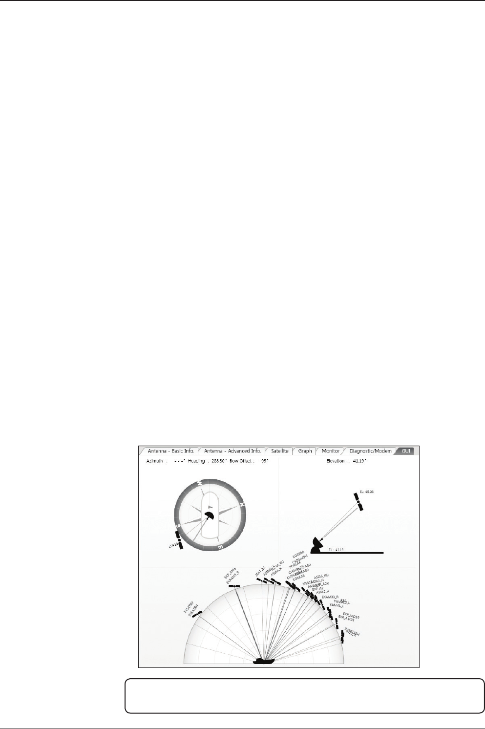
129
Aptus®
· Use Modem Lock: selects whether or not to use external lock
signal from the Modem. “Use Modem Lock” will only be activated
when the Modem protocol is set as I/O Console.
· TX Mute: TX Mute is a transmit inhibit output from the ACU to dis
able /mute the Modem transmit through a 5 V (HIGH) or 0 V (LOW)
current whenever the antenna is blocked, searching, or is mis-
pointed 0.5 degrees from peak satellite position. TX Mute will only
be activated when Modem protocol is set as I/O console.
· Modem Lock: is the Modem lock output from the Modem. It pro
vides a logic input through a 5V (HIGH) or 0 V (LOW) current to the
ACU to identify when the system is on the correct satellite.
“Modem Lock” will only be activated when Modem protocol is set
as I/O Console.
7. GUI
This view shows a graphical representation of the current antenna position which
allows you to easily identify whether or not the antenna is aligned properly to the
target satellite or is in a blockage zone. In addition, this view shows the current
satellite that the antenna is pointed towards and the satellites that are located at a
180° arc on the horizon, according to the current position.
NOTE: Based on the satellite EIRP footprint and the size of the antenna,
you may not be able to track all the satellites visible in 180° arc.
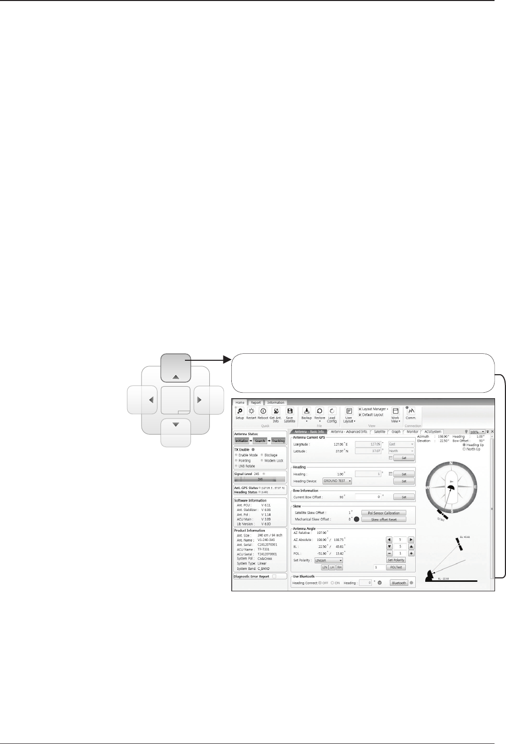
v240C – Marine Satellite Communication System
130
8. Work View Functions
The seven Work View Tabs displayed in the Work View can be arranged in cus-
tomized layouts.
- Layout Formatting
· Each of the Work View Tab can be separated from the rest Tabs.
Click and hold the left mouse button on the Work View Tab’s
header and then drag a desired Tab out. When a Work View Tab
is separated from the rest of your Work View Tabs, again click
and hold the left mouse button on the Work View Tab’s header to
display a cross-shaped Navigator icon. While holding the mouse
button, bring the selected Work View Tab closer to the Navigator
icon and release the mouse button at your desired position (top,
left, right or bottom arrow). This time, the selected Tab will be
moved to the desired position.
Move the selected Work View Tab to the top position of the
Work View layout. (See example gure below where Antenna –
Basic Info Tab is moved to the top)
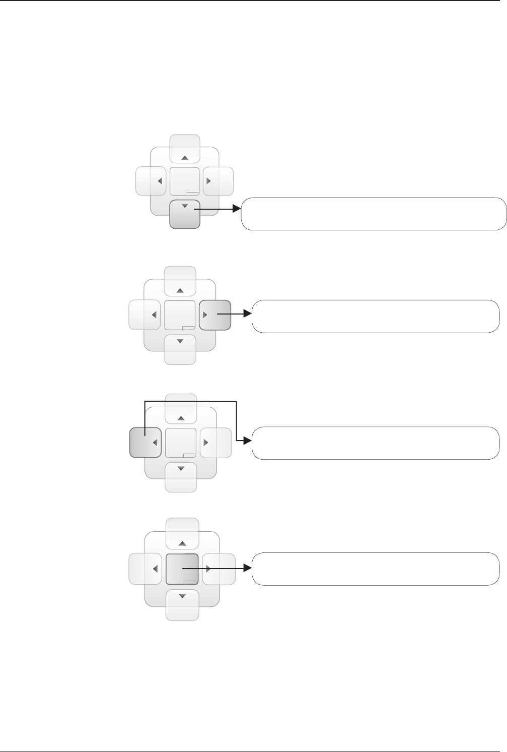
131
Aptus®
Move the selected Work View Tab to the right position of
the Work View layout.
Move the selected Work View Tab to the left position of
the Work View layout.
Move the selected Work View Tab to the center position
of the Work View layout.
Move the selected Work View Tab to the bottom position of
the Work View layout.
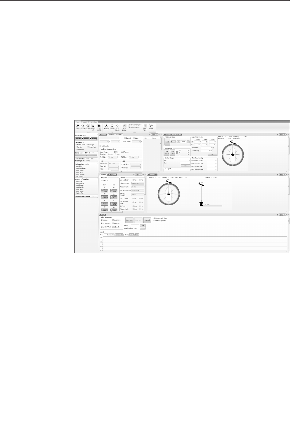
v240C – Marine Satellite Communication System
132
You can also drag multiple Work View Tabs into a customized layout in the same
manner. Click and hold left mouse button on each Work View Tab’s header and
drag it onto a desired arrow on the Navigator icon. Then each Work View Tab can
be placed to the desired positions as shown in the gure below.
The Navigator will appear in each area your mouse pointer is located. To return to
the default layout, select the Default Layout toolbar menu.
- Horizontal or Vertical Tab Group
The Work View Tabs can be also aligned horizontally or vertically. Without
dragging them out, right-click the mouse button on a desired Tab header
and select ‘New Horizontal Tab Group’ or ‘New Vertical Tab Group’
option. Selecting ‘New Horizontal Tab Group’ will separate a selected Tab
from the rest of other Tabs then arrange it in a horizontal format. Likewise,
selecting ‘New Vertical Tab Group’ will separate a selected Tab from the
rest of other Tabs then arrange it in a vertical format.
- Closing the Work View Tab
To close the Work View Tab, right-click the mouse button on a desired
Tab header and select ‘Close’ option in the drop down list. To close all
Work View Tabs except the selected Tab, select ‘Close All But This’
option in the drop down list.
- Zoom Tool
Using the Zoom tool, you can easily select the magnication you want by
using Zoom In and Zoom Out bar, and Fit in Work View button.
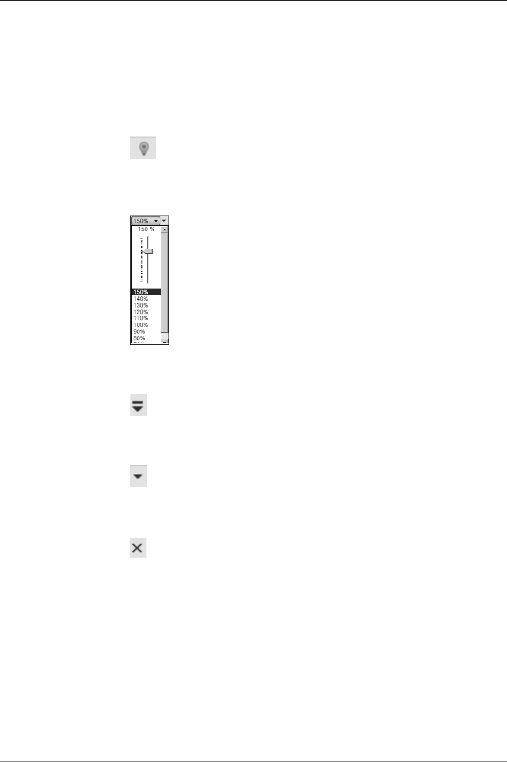
133
Aptus®
Fit Work View Button: ts the current view to the Work View window size. The but-
ton toggles between the t view and the previous view.
Zoom In and Zoom Out Bar: zooms in and out to expand and reduce the View to
the desired size. (The zoom changes in 10% increments.)
View Switch Button: displays a list of the current views in a list. Choosing one of
these views will display the selected view in the Work View window.
View Name Button: displays the current Work View name.
Close View Button: closes the current view.

v240C – Marine Satellite Communication System
134

135
Aptus® WEB
Aptus® WEB
Introduction
Main Page
Page Login
Top Menus
Dash Board & Information
Antenna Settings
Ship setting
Antenna Position & Parameters
Tracking setting
Modem Setting
Diagnostic
Library Setting
Firmware & Conguration
Antenna Firmware Upgrade
Antenna Log
Antenna Backup & Restore
Administration
Network Setting
SNMP Setting
User Management
iARM Upgrade
iARM Save & Reboot
Antenna Event Log
Intellian Network Devices
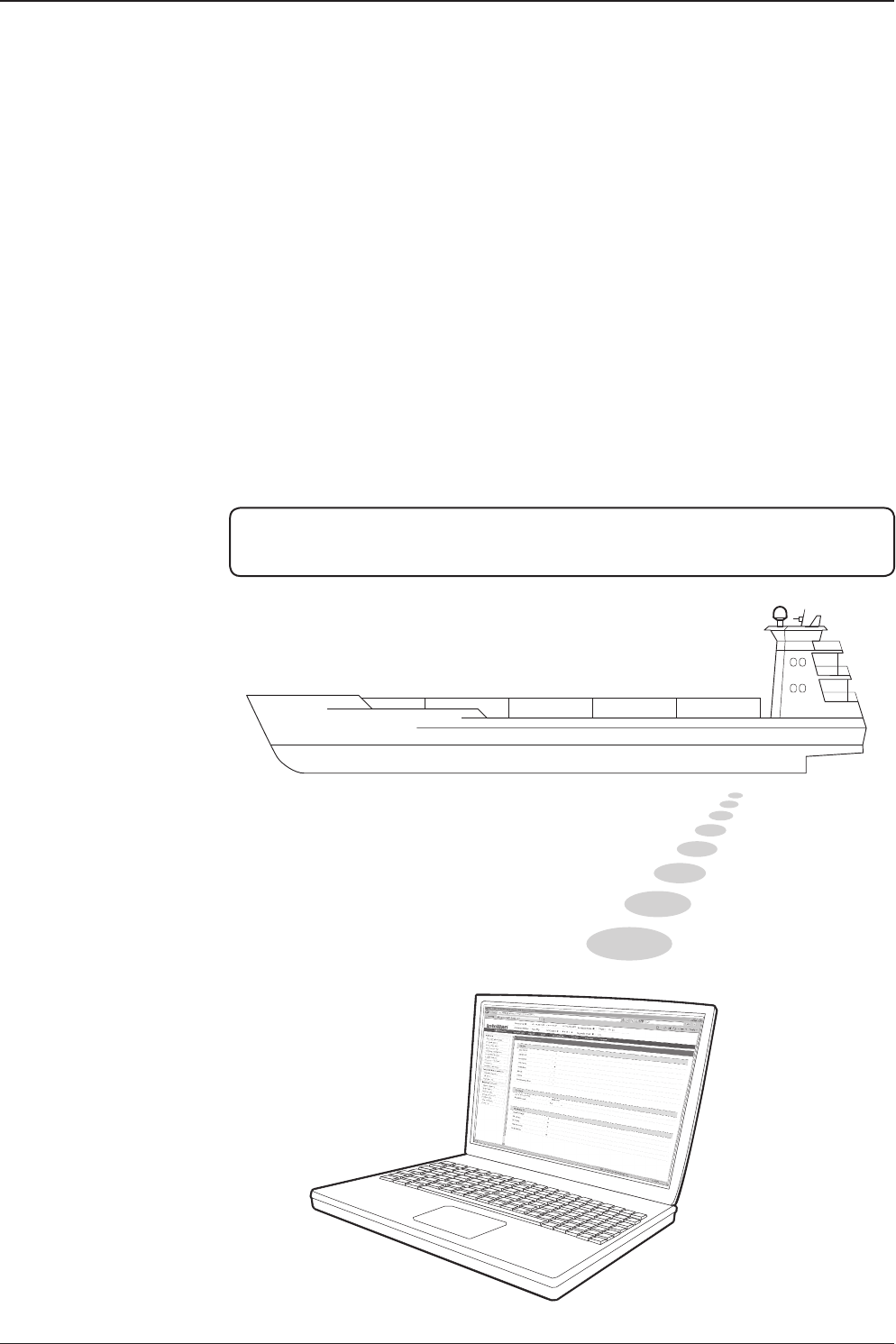
v240C – Marine Satellite Communication System
136
Introduction
With embedded Aptus Web function, the v-Series can be monitored, controlled, and
diagnosed remotely from anywhere, anytime through the TCP/IP protocol. This not
only can save time but also save the cost generated from the hundreds of routine
maintenance activities such as operating rmware upgrades, tracking parameters
resets, and system diagnostic.
How to access Aptus Web :
1. Connect an Ethernet Cable between your PC and the Management Ethernet Port.
2. Enter the ACU's IP address (192.168.2.1) into your web browser's address bar to
login into the ACU’s internal HTML page, if this system has not been changed from
the ACU’s factory default.
NOTE: Aptus Web can be displayed in Internet Explorer 7 or later and is also compatible
with Firefox and Chrome web browser.
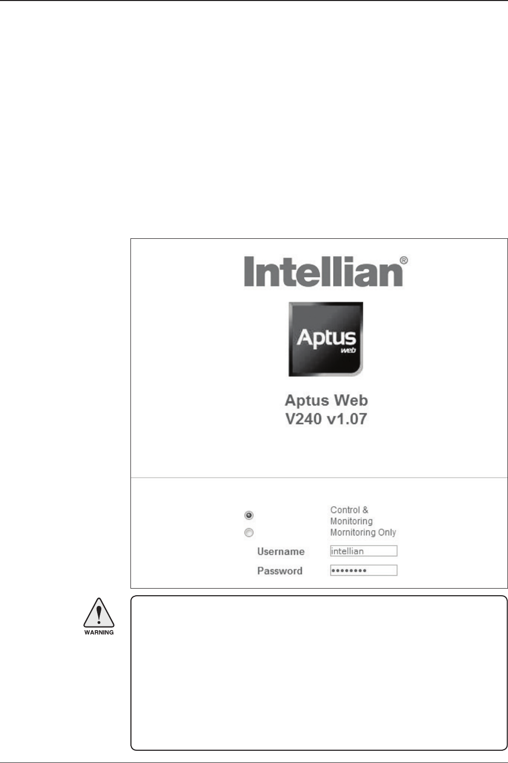
137
Aptus® WEB
Page Login
1. Choose either to Control & Monitor the ACU (Control & Monitoring) or Only
Monitor the ACU (Monitoring Only).
2. Log into the ACU by typing in User Name and Password information. If this
system has not been changed from the factory default:
• User Name: intellian
• Password: 12345678
WARNING: The Control & Monitoring menu will be switched to the Monitoring
Only menu in the following cases;
• If Aptus is connected using TCP/IP Communication while Aptus Web Control
is in use.
• If Control & Monitoring menu is accessed while PC Software
is running via TCP/IP Communication. In this case, the web page
will display a pop-up message asking if you want to disconnect the PC
Software network connection. If you select ‘No’, the Control & Monitoring
menu will be switched to the Monitoring Only menu.
Main Page
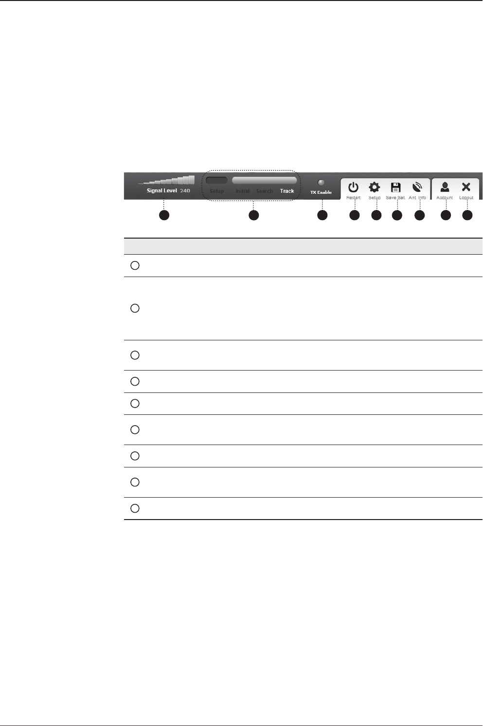
v240C – Marine Satellite Communication System
138
No. Item Description
1Signal Level Display current signal level.
2Antenna
status
- Setup: Displays whether or not the antenna is in SETUP
MENU. The indicator shows “Blue” in the SETUP MENU.
- Initial: Antenna or ACU is initialized.
- Search: Antenna is searching a target satellite.
- Track: Antenna is tracking the target satellite.
3TX Enable/
TX Disable
Displays whether or not the antenna is able to transmit the
data
4Restart Restart the antenna system.
5Setup Enter SETUP MENU.
6Save Sat. Save current satellite settings.
Bow offset will be adjusted and saved automatically.
7Ant. Info Obtain current antenna information.
8Account Shortcut to User Management menu. Change login ID and
Password.
9Logout Logout the ACU's internal HTML page.
Top Menus
Once you log in, the following information and menus are displayed.
1 3 4 5 678 9
2
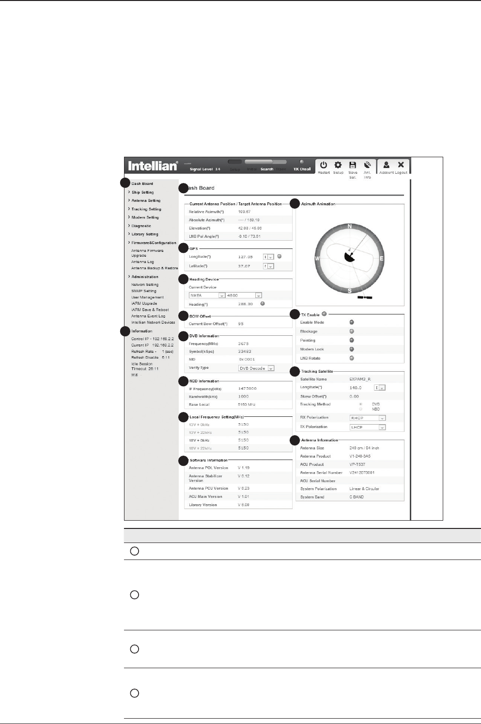
139
Aptus® WEB
No. Item Description
1Dash Board Displays current antenna status to be quickly monitored.
2
Current Antenna
Position /
Target Antenna
Position
Displays current antenna position.
- Relative Azimuth: displays antenna relative AZ angle.
- Absolute Azimuth: displays antenna absolute AZ angle.
- Elevation: displays antenna elevation angle.
- LNB Pol Angle: displays LNB pol angle.
- Heading: displays ship’s heading information
3GPS
Displays current GPS information.
- Longitude (East / West)
- Latitude (North / South)
4Heading
Device
Displays current Heading Device: NONE, NMEA, NMEA 2000,
Ground test If the ship’s gyro input is other than NMEA sepa-
rate purchase of GYRO Converter is required.
- Heading: displays ship’s heading information.
Dash Board & Information
On the left side of the page, Dash Board and Information menus are displayed
as below to provide quick monitoring of the antenna status and settings. Other
menus are displayed only in the Control & Monitoring MENU and their functions
will be described in the next sections.
1
3
4
5
6
7
8
9
10
11
12
13
14
2

v240C – Marine Satellite Communication System
140
5BOW Offset Display current bow offset
6DVB Information
Displays DVB tracking MENU’s current tracking information.
- Frequency: displays tracking frequency.
- Symbol rate: displays symbol rate.
- NID: displays network ID.
- Verify type: displays verication typ
(AGC, DVB, DVB Decode)
7NBD Information
Displays NBD tracking MENU’s current tracking information.
- Frequency: displays tracking IF frequency.
- Bandwidth: displays detection bandwidth.
8Local Frequency
Setting (MHz) Displays current LNB’s local frequency and voltage
9Satellite
Information
Displays current Antenna and ACU rmware versions and Satellite
Library version installed in the system.
- Antenna POL Version
(It will display "v-----" if there is no Pol Control Board installed.)
- Antenna Stabilizer Version
- Antenna PCU Version
- ACU Main Version
- Library Version
10 Azimuth
Animation
Shows a graphical representation of the current antenna position
to identify whether or not the antenna is aligned properly to the
target satellite or is in a blockage zone.
11 TX Enable
Displays whether or not the antenna is able to transmit the data.
The TX function will only be enabled (shows BLUE dot ) only if all of
the factors listed below shows “BLUE” dot. Exception: If “Use TX
Mute” is set as “NO”, the TX function will be enabled regardless of
which factor listed below shows “gray” dot or “red” dot.
- Enable MENU: antenna is not in SETUP MENU.
- Blockage: antenna is not facing the predened block zone(s). -
Pointing: antenna is pointing to the target satellite.
- Modem Lock: satellite Modem is sending a logic input to the
ACU to identify when the antenna tracks on the correct satellite.
- LNB Rotate: LNB is not rotating.
12 Tracking
Satellite
Displays current tracking MENU.
- Satellite: displays satellite name.
- Longitude: displays satellite orbit position.
- Skew Offset: displays Skew offset.
- Tracking Method: displays current tracking MENU (DVB/ NBD).
- RX Polarization: displays current RX polarization.
- TX Polarization displays current TX polarization.
13 Antenna
Information Displays the product information
14 Information
- Control IP: Displays current IP that controls the ACU.
- Current IP: Displays current IP address.
- Refresh Rate: Displays screen refresh rate (default: 1 sec.)
- Refresh Disable: Displays time out.
The screen will not refresh once the time-out shows 0:00.
Exception: If the Refresh Disable Time is set to “OFF” in the
Network Setting page, then the clock will show “--:--“ and
system will keep monitoring all activities regardless of timeout.
- Wi : Displays Wi on/off switch
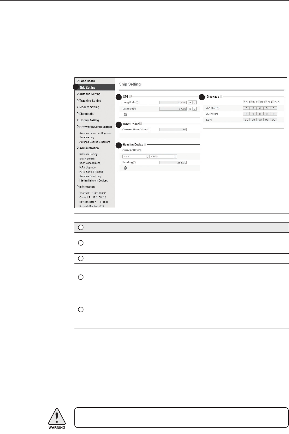
141
Aptus® WEB
No. Item Description
1Ship Setting Set the ship information and blockage zone.
2GPS
Set GPS information.
- Longitude (East/West)
- Latitude (North/South)
3Bow Offset Set Bow Offset if needed.
4Heading Device Set ship’s heading device (NONE, NMEA, NMEA2000,
Ground Test) and ship’s heading information
5Blockage
Set the antenna’s blockage zones up to 5 by azimuth and
elevation sectors. AZ. START is where the relative azimuth
starts and AZ. END is where the relative azimuth ends
(Range: 0 - 360°). EL. Limit is where the elevation starts
(Range 0 - 90°).
WARNING: Enter the SETUP MENU for conguration. Tick the checkbox before
modifying the settings. After conguration, click ‘Set ...’ button to submit the settings.
Ship Setting
Antenna Settings
1
3
4
5
2

v240C – Marine Satellite Communication System
142
Antenna Position & Parameters
No. Item Description
1Antenna Setting
Set current antenna position and Search and Track-
ing parameters. These parameters should only be
changed by an authorized service technician. Im-
proper setting of these parameters will render your
system inoperable.
2Current Antenna Position/
Target Antenna Position
Display current antenna position.
-
Relative Azimuth: display antenna relative AZ angle.
-
Absolute Azimuth: display antenna absolute AZ angle.
- Elevation: display antenna elevation angle.
- LNB Pol Angle: display LNB pol angle.
- Heading: display ship’s heading information.
3Manual Movement
Move antenna azimuth and elevation angles and
LNB pol angle to nd the desired satellite manually.
LNB Pol Angel can be adjusted at any time either in
SETUP MENU or Tracking MENU.
4LNB Pol Sensor Calibration Calibrate the LNB pol angle when the control board,
potentiometer or belt is replaced.
1
3
4
5
6
7
8
9
10
11
2
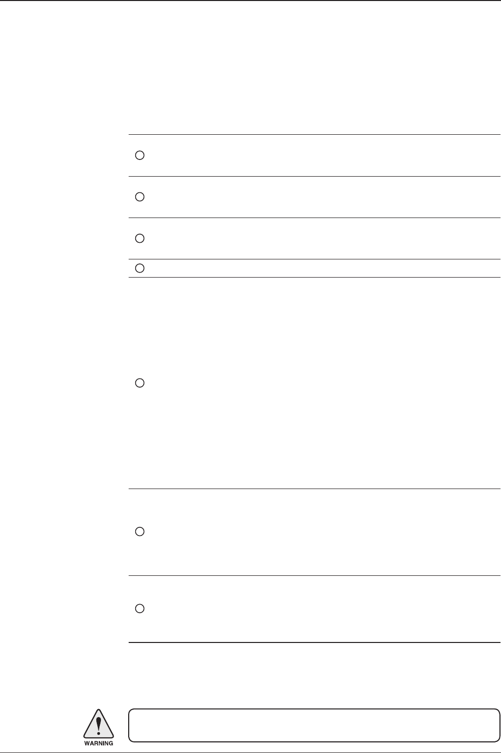
143
Aptus® WEB
WARNING: Tick the checkbox before modifying the settings. After conguration, click
'set...' button to submit the settings.
5Elevation Adjust
Adjust the elevation to offset the angle difference
between the mechanical elevation angle and actual
elevation angle.
6Conical Range
The relative force of the motors controlling azimuth
and elevation. Set the conical range while the an-
tenna is in tracking MENU.
7Idle MENU
Release the elevation and cross level motor brakes
while the antenna is in SETUP MENU. The antenna
can be moved manually during the MENU.
8Reboot Reboot the system.
9Search & Tracking
Parameter Setting
DVB Detect and Tracking Level Threshold: display /
set current detect level threshold and tracking level
threshold when DVB tracking MENU is chosen to be
used.
- NBD Detect and Tracking Level Threshold: display
/ set current detect level threshold and tracking level
threshold
when NBD tracking MENU is chosen to be used.
- TX Enable Threshold: display / set TX enable
threshold. - Wait time: set the time-out for automat-
ic initiation of a search after the signal level drops
below the pre-dened threshold value.
- Search Step: set increment step size.
- Search 1 & 3 Range: set Search 1 & 3 search
range. Search is conducted in a two-axis pattern
consisting of alternate movements in azimuth and
elevation as forming expanding square.
- Search 2 Range: is reserved for future use.
10 Tilt Sensor Bias
Adjust the two solid-state tilt sensors used to
provide absolute cross-level tilt of the antenna and
elevation feedback to eliminate long-term point-
ing drift (error). Tilt bias is required to be adjusted
when the antenna control board or sensor box is
replaced. Check to see whether or not the bubble is
located at the center of the level vial.
11 Rate Sensor Adjust
Calibrate DC voltage output from the three rate
sensors used to sense antenna motion in azimuth,
elevation and cross-level axes. During the calibra-
tion process, the antenna should avoid any motion
as it can affect the antenna’s performance.
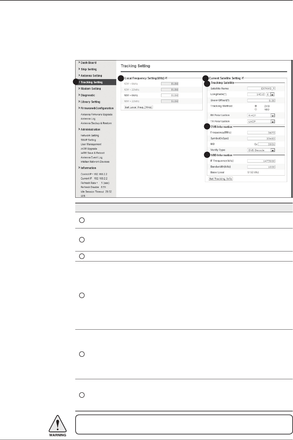
v240C – Marine Satellite Communication System
144
Tracking Setting
No. Item Description
1Tracking Setting Display or set current tracking MENU and tracking
frequency of the target satellite.
2Local Frequency Setting
(MHz)
Display and set LNB’s local frequencies. Display
current LNB local frequency which is in use and
voltage.
3Current Satellite Setting Display and set current satellite setting.
4Tracking Satellite
Display and set current tracking MENU.
- Satellite: display and set satellite name.
- Longitude: display and set satellite orbit position.
- Skew Offset: display and set Skew offset.
- Tracking Method: display and set current tracking
MENU (DVB/ NBD).
- RX Polarization: display and set current RX
polarization.
- TX Polarization display and set current TX
polarization.
5DVB Information
Display and set DVB tracking MENU’s tracking
information.
- Frequency: display and set tracking frequency.
- Symbol rate: display and set symbol rate.
- NID: display and set network ID.
- Verify type: display and set verication type (AGC,
DVB, DVB Decode)
6NBD Information
Display and set NBD tracking MENU’s tracking
information.
- Frequency: display and set tracking IF frequency.
- Bandwidth: display and set detection bandwidth.
WARNING: Tick the checkbox before modifying the settings. After conguration, click
'set...' button to submit the settings.
13
4
5
6
2
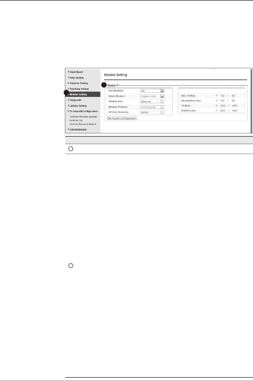
145
Aptus® WEB
Modem Setting
1
2
No. Item Description
1Modem Setting Set the Modem interface.
2Modem
- Use Mediator: enable the usage of Mediator if the antenna is
connected to the Intellian Dual VSAT Mediator. Use Mediator
must be set to “NO” if there is no MEDIATOR connected to the
ACU. Improper setting of this parameter will cause your ACU’s
Modem interface to work incorrectly.
- Select Modem: is to select a proper data communication port
and protocol on the ACU to interface with the satellite Modem.
The settings related to the Modem interface will be set auto-
matically once the Modem type is selected (USER SETTING,
IDIRECT-I/O, IDREICT-AMIP, COMTECH-I/O, COMTECH-
ROSS, HUGHES, SATLINK-SERIAL, SATLINK-VACP, ELEK-
TRIKOM-AMIP, GILAT-SE-II, IPSTAR-SOTM).
However, it is required to set the related settings separately if
USER SETTING is selected.
- Modem Port: is to select a proper data communication port
on the ACU to interface with the satellite Modem (RS232/422/
Ethernet).
- Modem Protocol: is to select a proper communication pro-
tocol on the ACU to interface with the Modem (I/O Console,
OpenAMIP, Serial GPS, ROSS, VCAP).
- GPS Out Sentence: is to select the GPS out sentence type
(GPGLL/GPGGA/SIMPLE GPGGA)
- USE TX Mute: is to select whether or not to use TX mute
function from the satellite Modem.
- USE Modem Lock: is to select whether or not to use external
lock signal from the satellite Modem.
- TX Mute: is a transmit inhibit output from the ACU to disable/
mute the Modem transmit through a 5V (High) or 0V(LOW)
current whenever the antenna is blocked, searching, or is
mispointed 0.5° from peak satellite position.
- Modem Lock: is the Modem lock output from the Modem
which provides a logic input through a 5V (High) or 0V(LOW)
current to the ACU to identify when it is on the correct satellite.
Note: TX Mute and Modem Lock items will only be activated
when the Modem protocol is set as I/O Console.
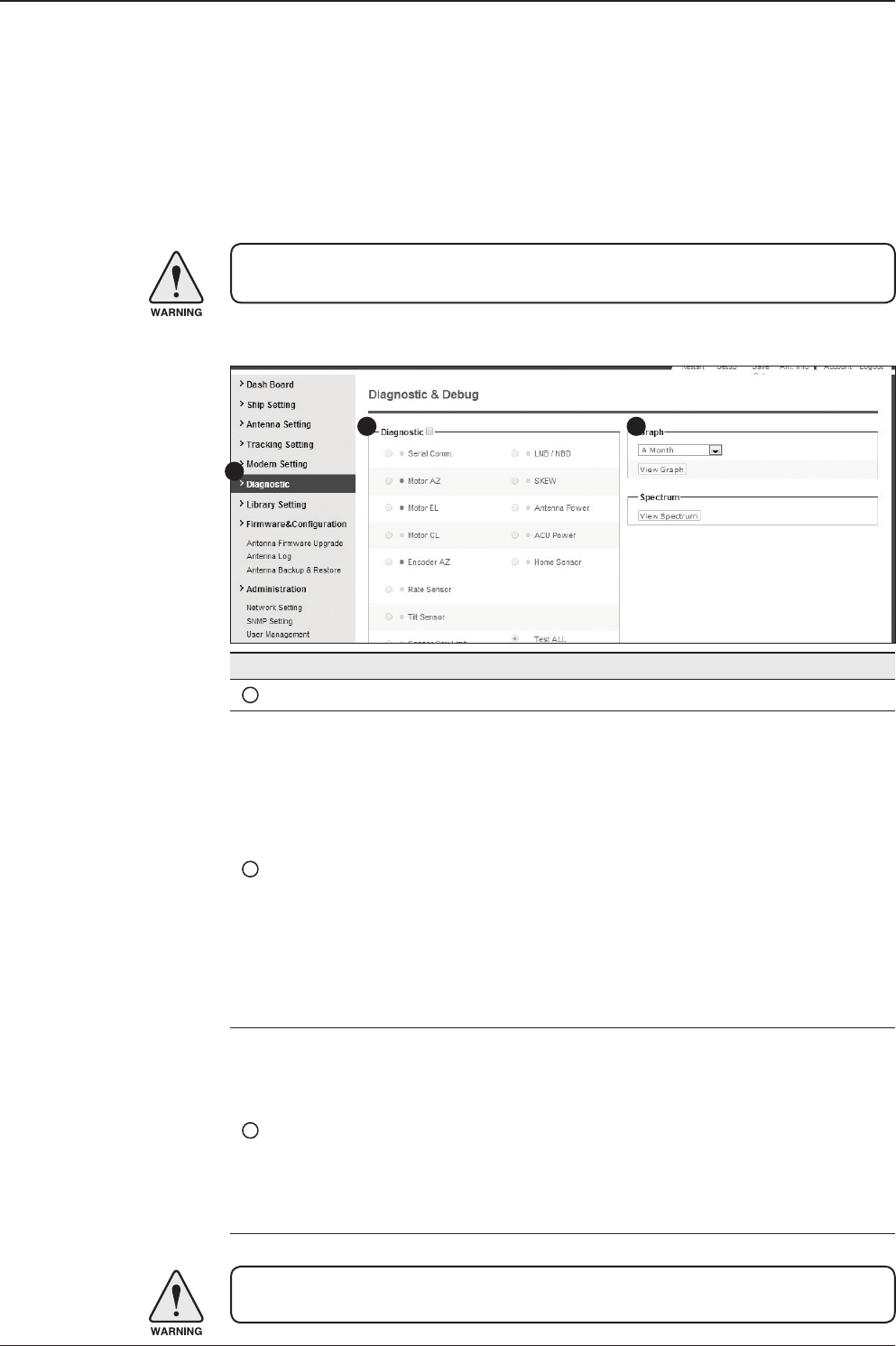
v240C – Marine Satellite Communication System
146
Diagnostic
No. Item Description
1Diagnostic Execute antenna diagnostic test.
2Diagnostic
Select to run a full diagnostic test or single diagnostic test.
- Serial Comm.: test the data communication between the
antenna and the ACU.
- Motor AZ: test the azimuth motor.
- Motor EL: test the elevation motor.
- Motor CL: test the cross-level motor.
- Encoder AZ: test the azimuth encoder.
- Rate Sensor: test the gyro sensor.
- Tilt Sensor: test the tilt sensor.
- Sensor Box Limit: test the sensor box motor.
- Home Sensor: test the home sensor.
- LNB/NBD: test the LNB.
- SKEW: test the LNB pol motor.
- Antenna Power: test the antenna power.
- ACU Power: test the ACU power.
3Graph
Select to view a graph of AZ Absolute, AZ Relative, EL and
Heading data of the antenna.
- A Month: display all data within a month
- A Week: display all data within a week
- A Day: display all data in a day
- Real-time: display data in real time. Press F5 button to refresh.
- Data Num: set the maximum number of graph data set to be
displayed.
- View Graph: select to view the data graph.
WARNING: Tick the checkbox before modifying the settings. Click Diagnosis button to
execute diagnostic test. To clear previous diagnosis result, click Diagnosis Clear button.
WARNING: Ensure to tick the checkbox before modifying the settings. Select ‘Set
Modem Conguration’ to conrm the Modem settings congured.
1
2 3

147
Aptus® WEB
4Spectrum Select to view a current spectrum graph and to set the spec-
trum display options.
5
iDirect Modem
Monitor
(OpenAMIP only)
Displays iDirect Modem status and control connection. This
menu appears only when IDIRECT-AMIP protocol is selected at
Modem Setting page.
- Connection: control modem connection.
- Modem IP: iDirect modem IP
- Port: Connection ID for telnet
- Password: Connection password for telnet
- Start(Stop): Connect to telnet or disconnect
- Auto Connect: Enabling Auto Connect and rebooting the ACU
will save connection data and will auto connect once ACU is
powered on next time.
- Status: Displays iDirect modem status
- Last Update Date: Displays last updated data and time of the
iDirect modem data
- Connect:Displays connection status (INACTIVE, CONNECT-
ING, LOGGEDIN, Black data indicates being INACTIVE)
- RX SNR: Displays RX SNR data.
- View Detail Information: Select to view detail information
- Status: Displays last update date and connection status.
- Information : Displays rx snr, tx power, tx power min, rx power,
tx power max, tx power, ref, latlong.
- Option File Information: Displays information about VERSION,
MOBILE, LOCAL and ACU PORT
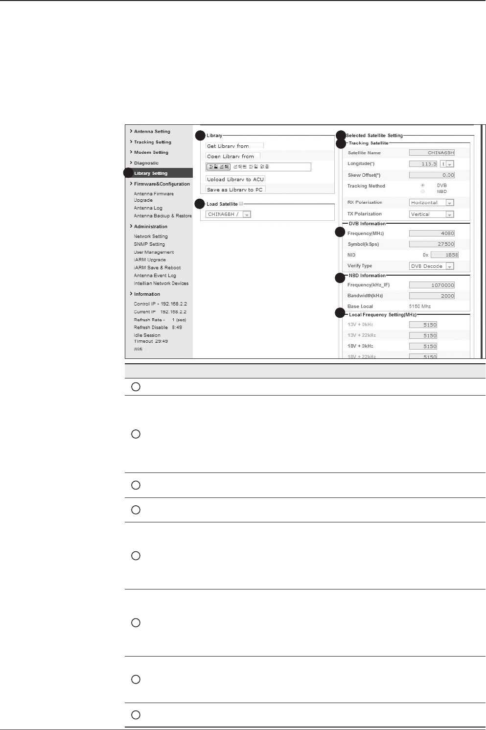
v240C – Marine Satellite Communication System
148
Library Setting
No. Item Description
1Library Setting Display and set the satellite library information.
2Library
- Get Library from ACU: Obtain satellite information installed in the
ACU.
- Open Library from PC: open the satellite library le from the
supplied Intellian CD or from the external hard drive/PC.
(File format: *.ilf)
- Upload Library to ACU: upload the satellite library le to ACU.
- Save as Library to PC: save the current library setting to the PC.
3Load Satellite
Select the satellite that you wish to track and press Load Satellite
button to load the selected satellite.
4Selected
Satellite Setting
Displays selected satellite information.
5Tracking
Satellite
- Satellite: displays satellite name.
- Longitude: displays satellite orbit position.
- Skew offset: displays Skew offset.
- Tracking method: displays current tracking MENU (DVB/NBD)
- RX polarization: displays current RX polarization.
- TX polarization: displays current TX polarization.
6DVB Information
- Displays DVB tracking MENU's tracking information.
- Frequency: displays tracking frequency.
- Symbol rate: displays symbol rate.
- NID: displays network ID.
- Verify type: displays verication type (AGC only, DVB lock, DVB
decode, DSS decode)
7NBD Information
Displays NBD tracking MENU's tracking information.
- Frequency: displays tracking frequency.
- Bandwidth: displays detection bandwidth.
8Local Frequency
Setting (MHz)
Displays LNB local frequency (MHz) and voltage.
1
3
4
5
6
7
8
2
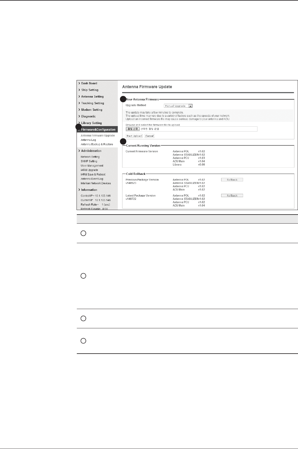
149
Aptus® WEB
Antenna Firmware Upgrade
Firmware & Conguration
No. Item Description
1Antenna Firmware
Upgrade Upgrade antenna and ACU rmware version.
2New Antenna
Firmware
Select Upgrade Method between Manual Upgrade or Auto
Upgrade. With Manual Upgrade option selected, browse and
select the rmware package le to upload and click Start
Upload button. With Auto Upgrade option selected, click
Check button to check automatically if there is new rmware
available from the server.
Note: Auto Upgrade is available only when the ACU is con-
nected to the Internet.
3Current Running
Version
Display current rmware version (Antenna STABILIZER,
Antenna PCU, ACU main, Library)
4Cold Rollback
Display Previous/Latest Package version and rollback
rmware to Previous or Latest version. Other functions
cannot be operated while rollback is in progress.
1
3
2
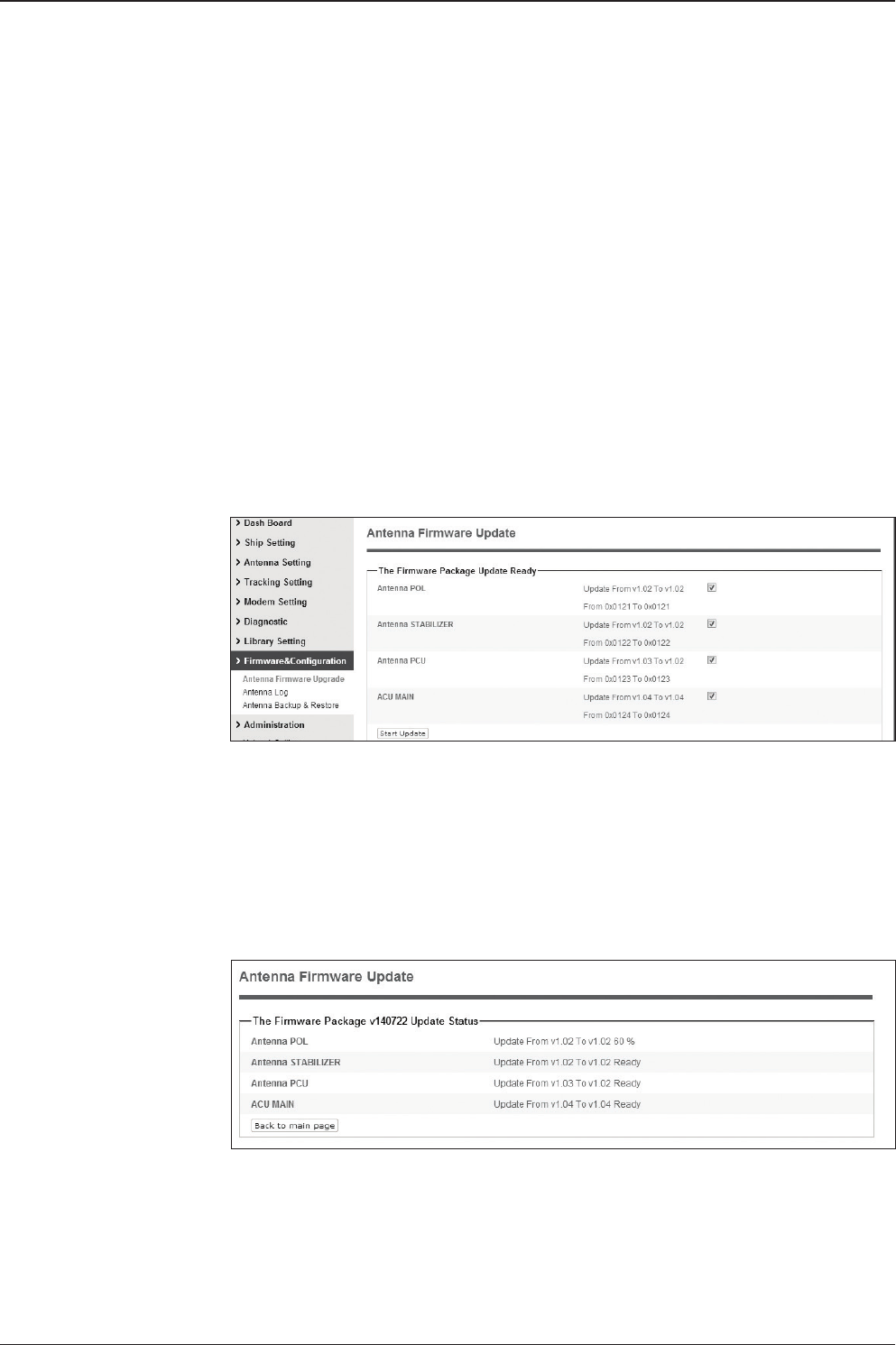
v240C – Marine Satellite Communication System
150
Firmware upgrade
status page
5. It'll display information about the upgrade process status on full screen.
Upgrade procedures:
1. Select the upgrade package le. In Auto Upgrade mode, check new rmware le
automatically by clicking Check button.
2. Click on “Start Upload” button to transfer the Firmware package le (“*.fwp”) to E2S
(Ethernet to serial) module. In Auto Upgrade mode, click "Upgrade" button once new
rmware le is detected.
3. After the package le is transferred, it’ll show “upgrade from vx.xx Version to vx.xx
Version”. Enable the check box to select the rmware le that you wish to upgrade.
To select all rmware les, click Select All Firmwares.
4. Click on “Start Upgrade” button.
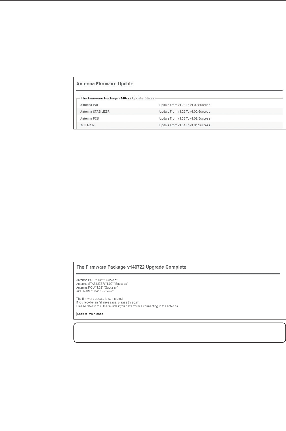
151
Aptus® WEB
Upgrade process
status page
6. If the rmware is successfully upgraded, it'll display "The rmware update is
completed."
7. Click on "Back to main page" to go out of the screen.
To verify the upgraded rmware version, go to Dash Board > Software Information.
Upgrade complete
page
NOTE: To roll back to the previous rmware package version or latest package version,
select Rollback Upgrade menu on the Antenna Firmware Upgrade page.
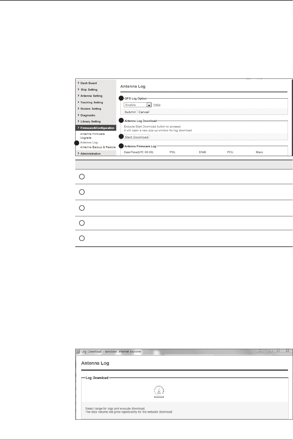
v240C – Marine Satellite Communication System
152
Antenna Log
No. Item Description
1Antenna Log Displays antenna log data
2GPS Log Option Disable/Enable to save GPS information in the antenna log le.
3Antenna Log
Download Download the log le. Select start download button to proceed.
4Start Download Download the antenna log information.
5Antenna
Firmware Log Display log information of rmware upgrade.
1
2
3
4
5
Log Downloade procedures:
1. Select ‘Start Download’ button.
2. To run Java applications you must have Java Runtime Environment
JRE) version 6.0 and above installed in your PC/ laptop when you
access the antenna log page for rst time. Click “Run” button on
the popup message “The application’s digital signature cannot be
veried. Do you want to run the application? ” to install the Applet.
Refer to Appendix for Java Installation Instructions if the system
does not display the popup message.
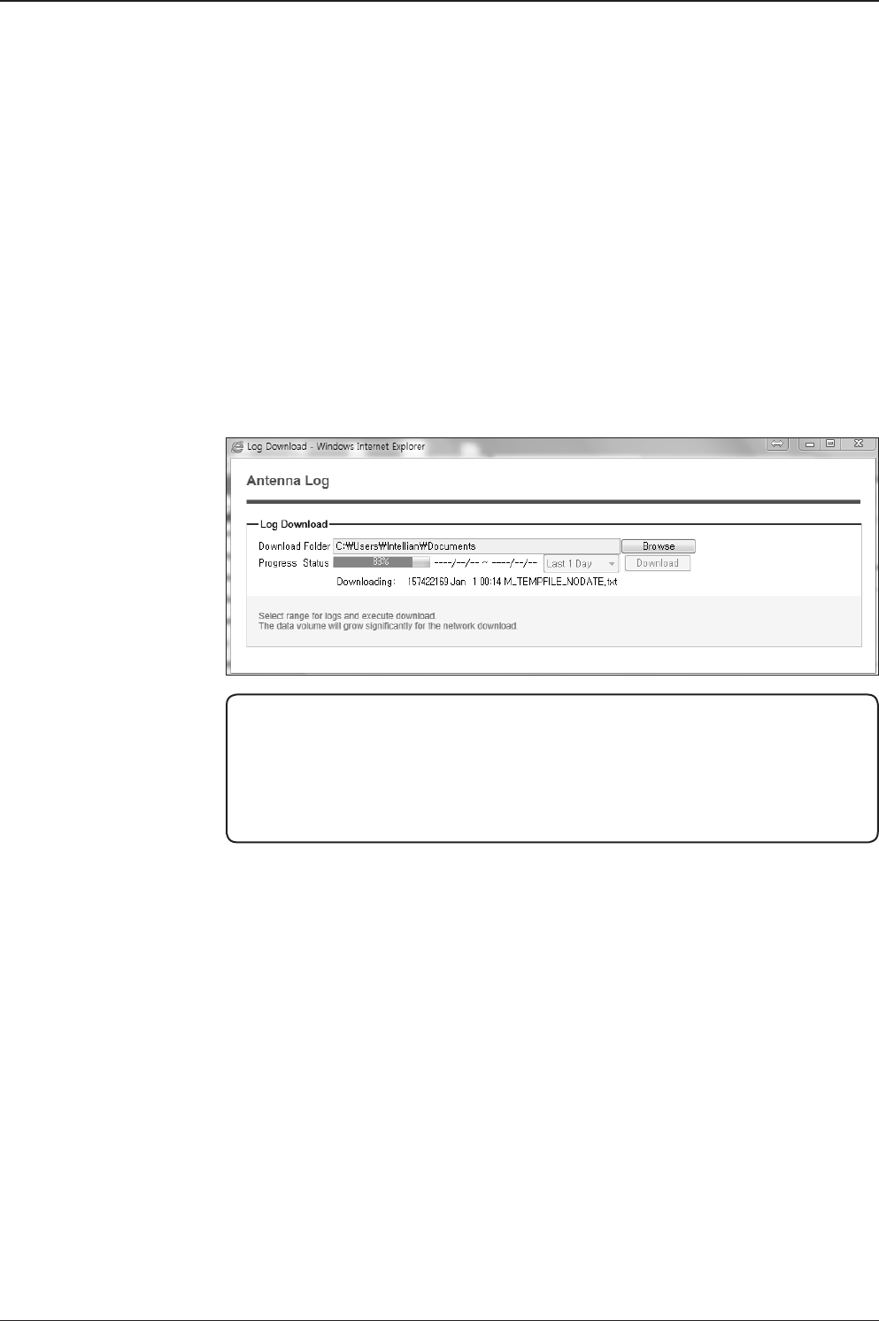
153
Aptus® WEB
3. Select ‘Browse’ to browse the target directory of the antenna log le.
4. Select log period for le download.
- Last 3 Months: download the antenna log information for the past three
months.
- Last 1 Month: download the antenna log informaiton for the past one month.
- Last 1 week: download the antenna log information for the past one week.
- Last 1 Day: download the antenna log information for the past one day.
5. Select ‘Download’to download the log le to the target directory according to the
selected log period.
NOTE: You can choose to Enable or Disable the GPS tracking function. Liability for
information that is disclosed when GPS is enabled is solely the operators responsibility
and it is up to the operator on whether or not to provide their GPS information to third
parties. Any issues regarding safety and privacy when turning on the GPS function is
solely up to the user. Intellian is not responsible for information that is disclosed when
the GPS function is enabled.
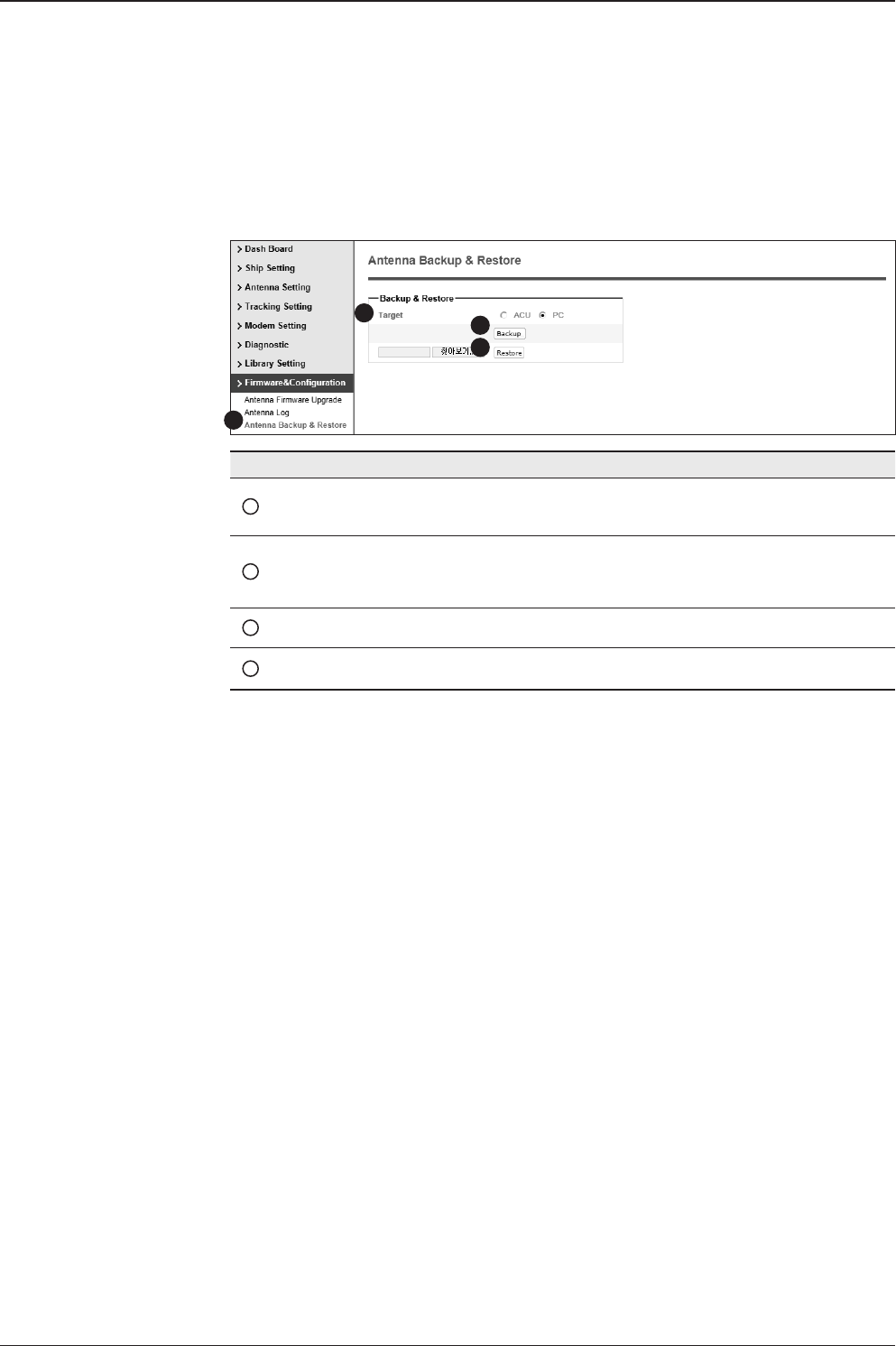
v240C – Marine Satellite Communication System
154
Antenna Backup & Restore
No. Item Description
1Antenna Backup & Restore Enter backup & Restore page. (Setup MENU is
required)
2Target
Backup antenna information to ACU/PC or
restore antenna by using the saved information
from ACU/PC.
3Backup Backup antenna information.
4Restore Restore antenna information.
1
3
4
2
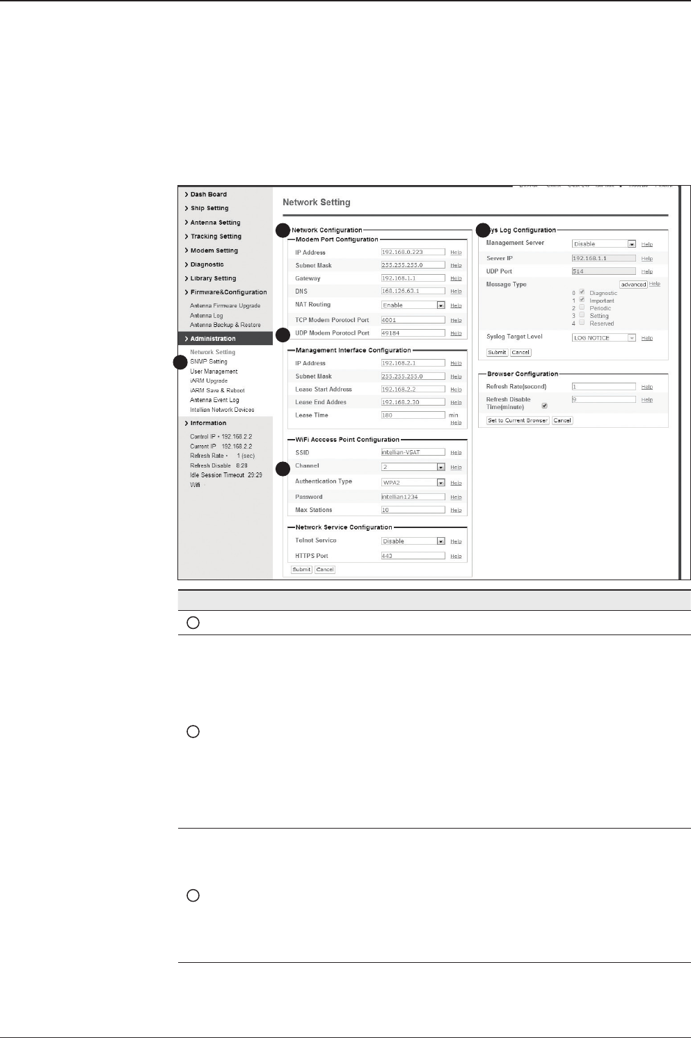
155
Aptus® WEB
Network Setting
1
3
4
5
2
No. Item Description
1Network Setting Enter network setting page.
2Modem Port
Conguration
Modify ACU’s Internal IP address and press Submit button. Go
to “Save & Reboot” page and press Save & Reboot button to
validate the changes.
- IP Address : Factory default(Primary:192.168.0.223)/
(Secondary:10.10.1.1).
- Subnet Mask : Factory default(255.255.255.0).
- Gateway : Factory default(192.168.0.254).
- DNS : Current default DNS Address is assigned to.
- NAT Routing : Enable/Disable NAT routing.
- TCP Modem Protocol Port : TCP port number for modem
protocols using TCP as transport.
- UDP Modem Protocol Port : UDP port number for modem
protocols using UDP as transport.
3
Management
Interface
Conguration
Modify Management Port’s network conguration and press
Submit button. Go to “Save & Reboot” page and press Save &
Reboot button to validate the changes.
- IP Address : ACU front network port /Factory default(192.168.2.1).
- Subnet Mask : Factory default(255.255.255.0).
- Lease Start Address : Lease IP address start range.
- Lease End Address : Lease IP address end range.
- Lease Time : Lease IP address update time.
Administration

v240C – Marine Satellite Communication System
156
4
Wi-Fi Access Point
Conguration
- SSID : The SSID is the network name shared among all
devices in a wireless network. The SSID must be identical
for all devices in the wireless network. It is case-sensitive
and must not exceed 32 alphanumeric characters, which
may be any keyboard character. Make sure this setting is
the same for all devices in your wireless network.
- Channel : Select an appropriate channel from the list
provided to correspond with your network settings. All
devices in your wireless network must use the same
channel in order to function correctly. Try to avoid conicts
with other wireless networks by choosing a channel where
the upper and lower three channels are not in use.
- Authentication Type : Module supports an authentication
mode that the 802.11 device uses when it authenticates and
associates with an access point or IBSS cell.
- Password : WiFi access password.
- Max Stations : Setting max stations.
5Network Service
Conguration
- Telnet Service : Enable or disable telnet login support.
- HTTPS Port : HTTPS port number.
6Sys Log
Conguration
Set the system log conguration.
Antenna sends log messages according to emergency level.
Enabling this function sends the message to your management
server.
- Management Server : Sys log function enable/disable
- Server IP : Management server IP address
- UDP Port : Management port
- Message Type : Select message type (Intellian message level)
to send to management server (Lower number indicates higher
emergency).
- Sys log Target Level : If you select this target level,
the management server receives log message equal to or less
than this level.
7Browser
Conguration
Setting refresh rate and refresh disable time.
- Refresh Rate : Set the browser refresh rate
(Default 1 seconds. Range 1~99).
- Refresh Disable Time : Set the browser idle time-out
(Default:9 minutes. Range 0~9). To use this function, check the
check box.
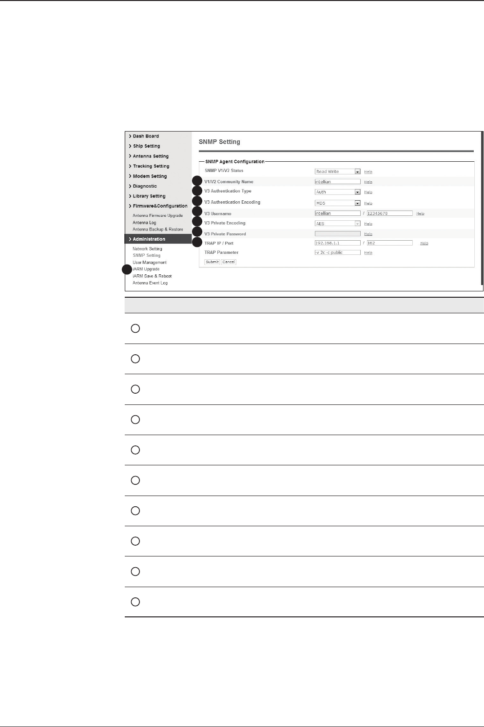
157
Aptus® WEB
SNMP Setting
1
3
4
5
6
7
8
2
No. Item Description
1SNMP Setting Congure SNMP settings.
2SNMP V1/V2 Status Set SNMP mode(Use Attribution Disable, Read Only
or Read Write).
3V1/V2 Community Name Set SNMP V2 community name.
4V3 Authentication Type Set SNMP V3 authentication mode.
5V3 Authentication
Encoding Set SNMP V3 authentication encoding.
6V3 Username Set the V3 username and password of the SNMP
Agent. The password is at least 8 character string.
7V3 Private Encoding Set SNMP V3 Private Encoding.
8V3 Private Password Set the V3 password of the SNMP Agent. The
Password is at least character string.
9TRAP IP/Port Set the V3 password of the SNMP Agent. The
Password is at least character string.
10 TRAP Parameter Set the SNMP trap specic parameter.
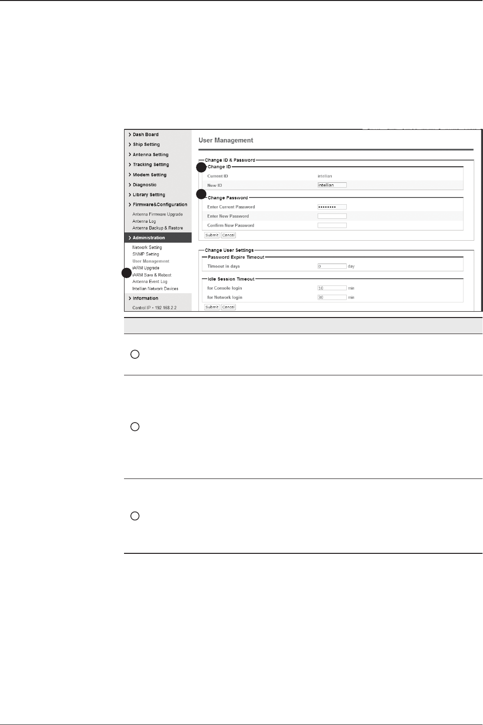
v240C – Marine Satellite Communication System
158
User Management
No. Item Description
1User Management
Change login ID and Password to access the Aptus Web.
This setting can be also accessed by ‘Account’ icon on the
top menu.
2Change ID
& Password
Change your login ID (user name) and password.
- Change ID : Enter your current login ID (user name) and
new login ID. Click the Submit button to validate the changes
that are made to the login ID.
- Change Password : Enter your current login password and
new login password. Click the Submit button to validate the
changes that are made to the login password.
3Change
User Settings
Change User Password Expire in days and Idle session time-out.
- Password Expire Time-out : Set password expire in days.
- Idle Session Time-out : Set for Console and for Network
time-out.
1
3
2
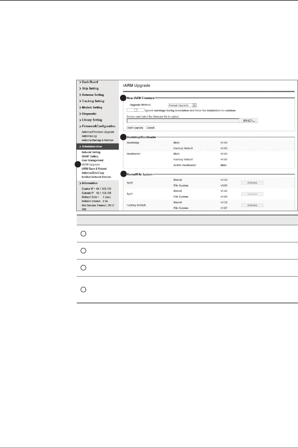
159
Aptus® WEB
iARM Upgrade
iARM rmware upgrade procedures:
1. Click on “Browse” button to select the iARM rmware le (.tgz) that you
wish to upgrade. In Auto Upgrade mode, check new rmware le automatically
by clicking Check button
2. Click on “Start Update” button to update the iARM rmware. Wait until
the page is loaded. In Auto Upgrade mode, click "Upgrade" button once new
rmware le is detected.
3. It’ll inform you that the rmware is being uploaded.
1
3
4
2
No. Item Description
1iARM Upgrade Upgrade the rmware of iARM module.
2Check New
iARM Firmware Check new iARM rmware available on the server.
3Bootstrap
/Bootloader Displays current bootstrap and bootloader version.
4Kernel
/File System
ACU has 3 storage parts sys0, sys1, Factory Default.
Display kernel and le system version and current activated
part Information.
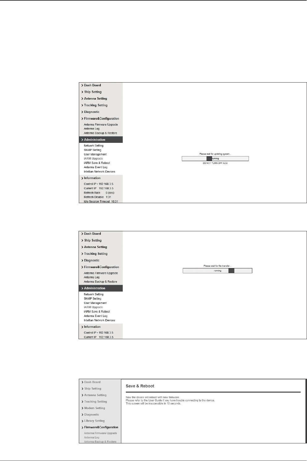
v240C – Marine Satellite Communication System
160
4. Do not turn off the ACU power if the rmware upgrade page is displayed.
5. It’ll take around 2 minutes to complete the rmware upgrade. Once the upgrade
is completed, the system will reboot automatically.
Firmware upload in
progress
Firmware upgrade in
progress
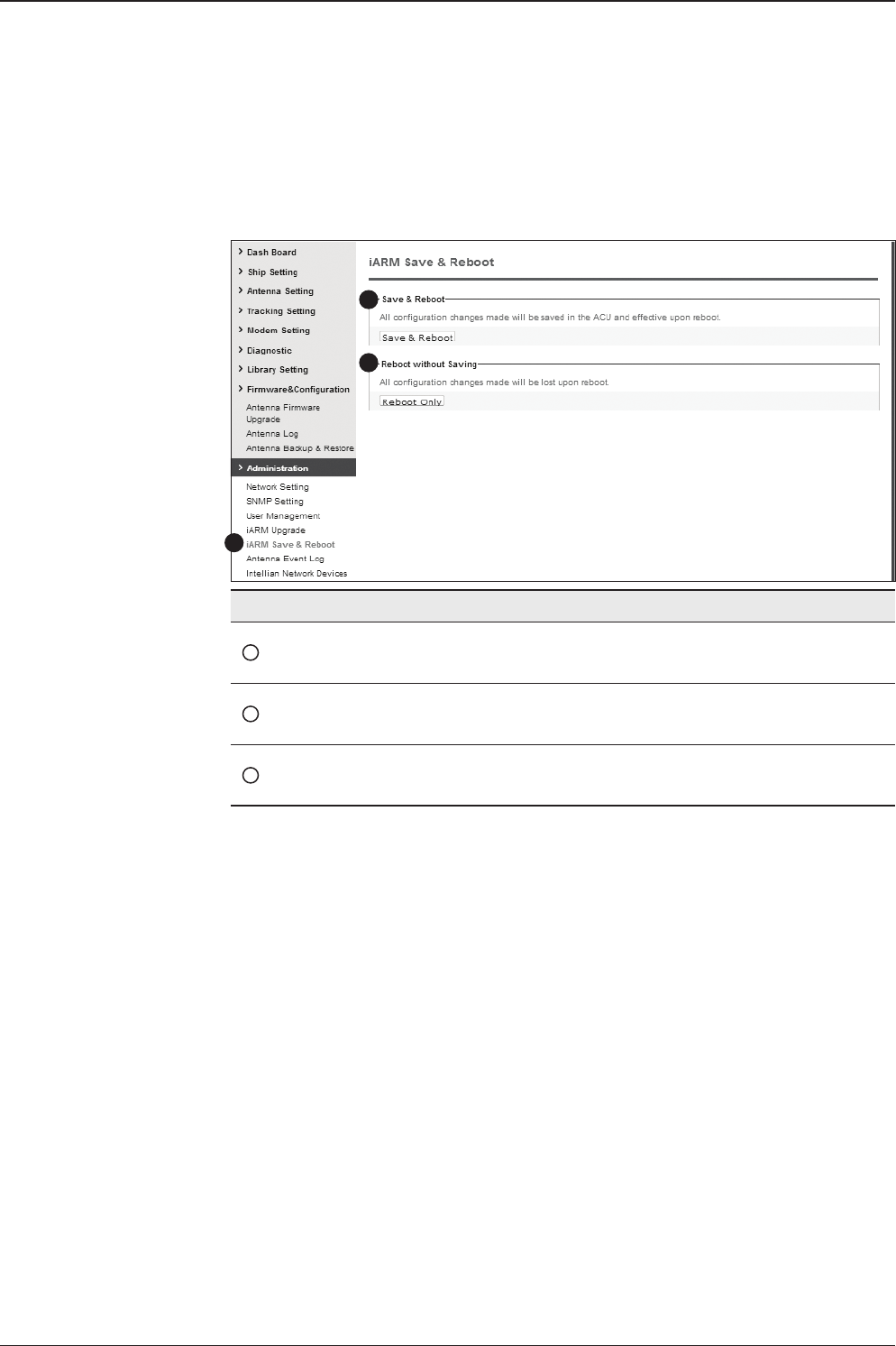
161
Aptus® WEB
iARM Save & Reboot
No. Item Description
1iARM
Save & Reboot
Save settings to the ACU and reboot or reboot the system
without saving.
2Save & Reboot Save the modied settings and reboot the system.
Click Save & Reboot button.
3Reboot without
Saving
Reboot the system without saving the modied settings.
Click Reboot Only button.
1
3
2
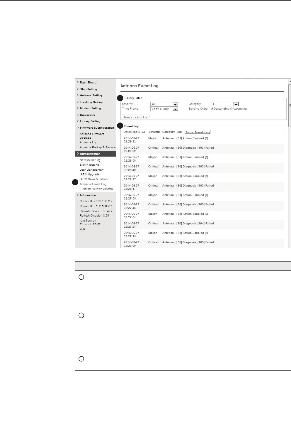
v240C – Marine Satellite Communication System
162
Antenna Event Log
1
2
3
No. Item Description
1Antenna Event Log Displays user's log information (Data/Time, Login ID and IP)
2Query Filter
Set the Log message option.
- Severity : Set urgency level.
- Category : Set target that caused the message.
- Time Frame : Set time limit that you want to show.
- Sorting Order : Sorting based on date
(descending or ascending).
3Event Log Displays log information (Date/Time, Severity, Category, Log).
- Save Event Log : Save log message to your PC.
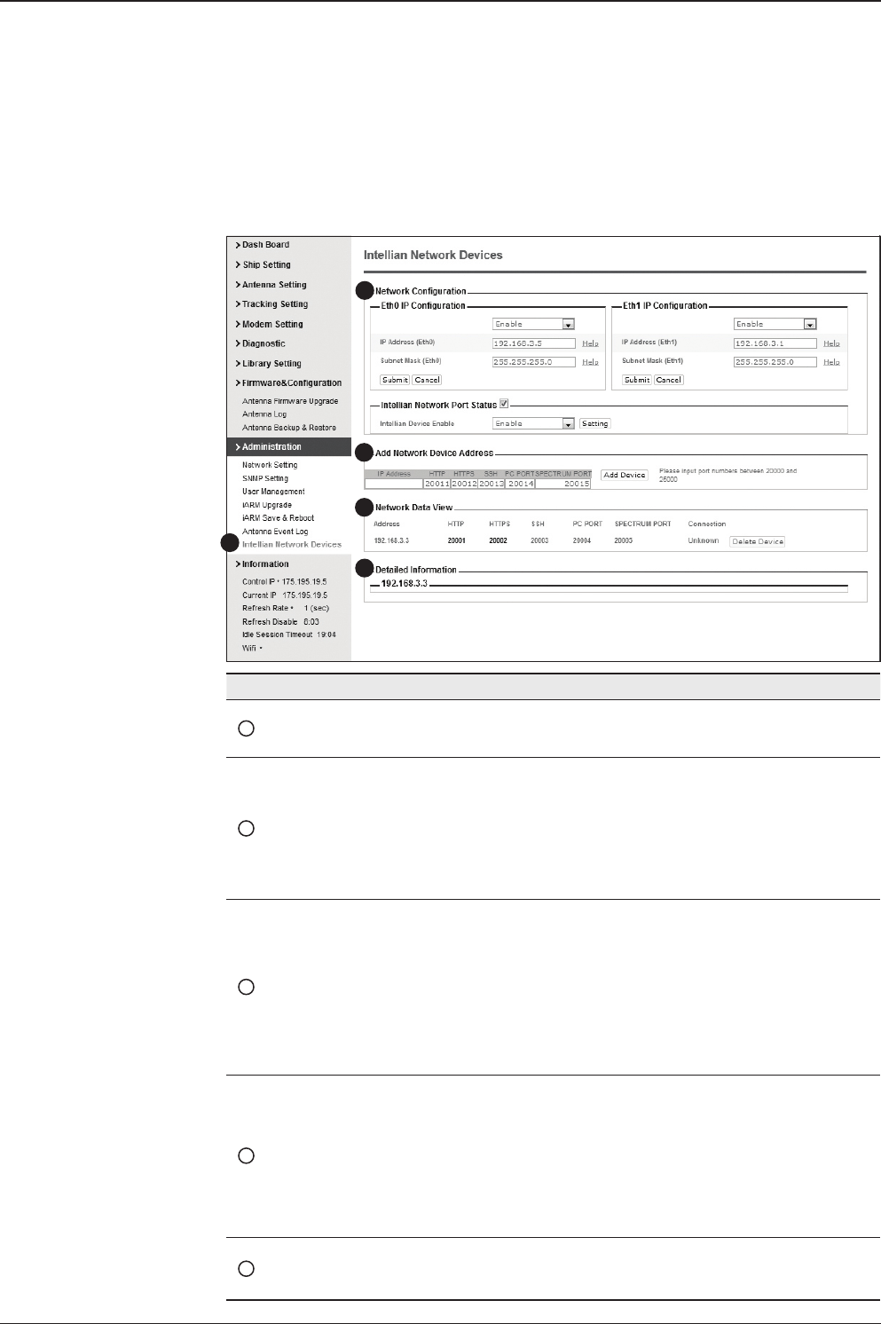
163
Aptus® WEB
Intellian Network Devices
1
3
4
5
2
No. Item Description
1Intellian Network
Devices
Add up to 8 network devices and enable to monitor real time
information of the connected device.
2Network
Conguration
• Eth0 IP Conguration : ACU network Eth0 IP and subnet
mask setting.
• Eth1 IP Conguration : ACU network Eth1 IP and subnet
mask setting.
• Intellian Network Port Status : not used on t-series.
3Add Network Device
Address
Add Intellian network devices, then you can browse the
various information of the device.
• IP Address : IP address of the device to be monitored.
• HTTP, HTTPS, SSH : Set port number(These port
numbers will be matched the http, https or SSH port
number of each device).
4Network Data View
Displays the setting information of the added device
(IP address, http, https, SSH port number, current
connection).
If you click the http/https port number of each device,
then you can connect to the device’s web page.
If you click Delete Device button, then you can’t see its
information.
5Detailed Information Displays the information of each device. (Updated every 3
second).
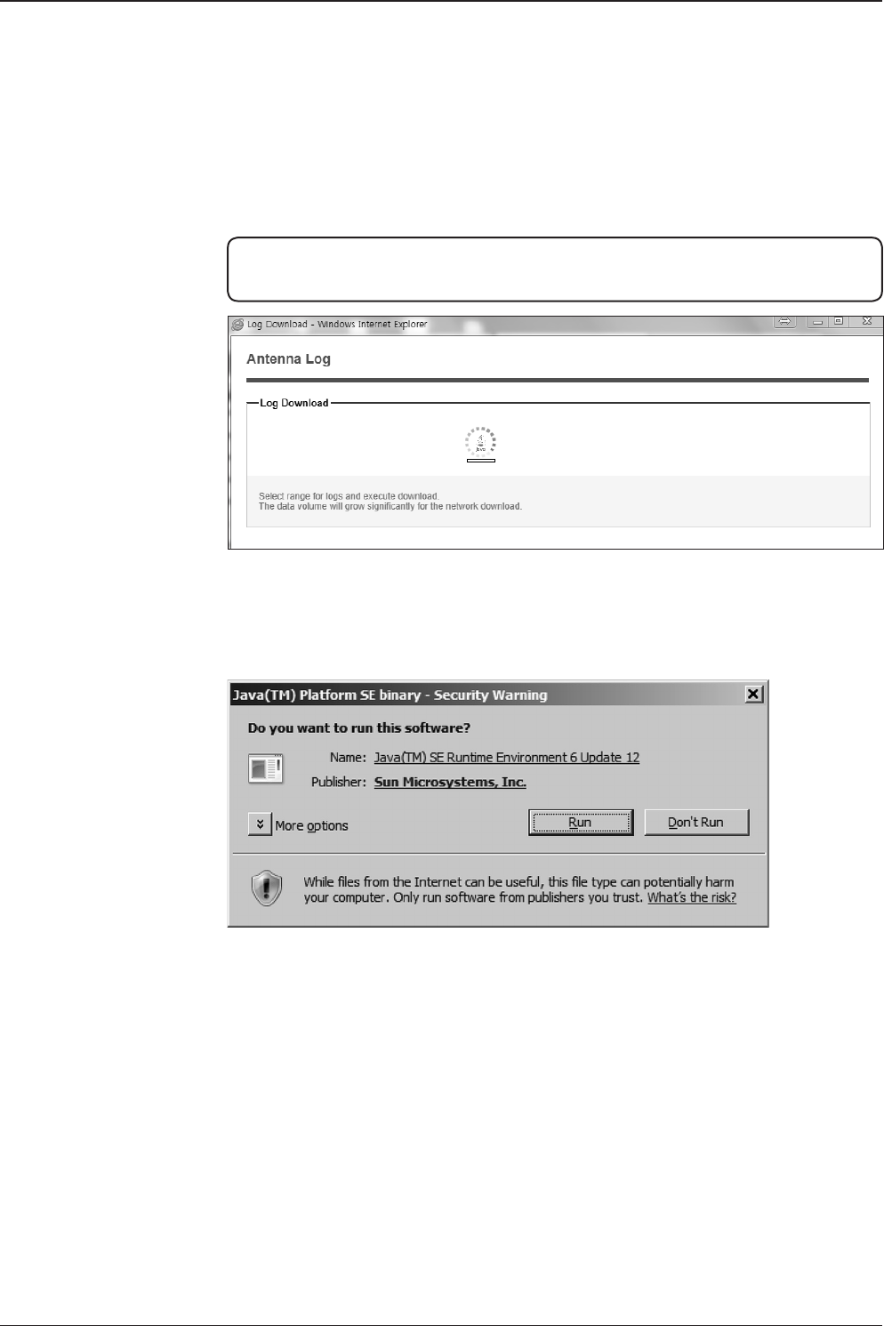
v240C – Marine Satellite Communication System
164
Appendix A: Java Download and Install Guide
NOTE: To run Java applications you must have Java Runtime Environment (JRE)
version 6.0 and above installed in your PC/laptop.
If JRE has not been installed in your PC/laptop, you’ll get the below message box.
Click Run button to install it through online or ofine download and install methods.
After installing JRE, Java Applet will be executed automatically when you access
the Antenna Log page.
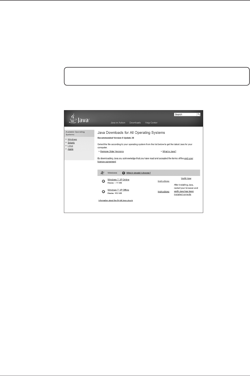
165
APPENDIX
NOTE: The JRE installation guide may vary depending on the operating system
installed in your PC/laptop.
Method 1. Online method for downloading and installing
http://www.java.com/en/download/manual.jsp
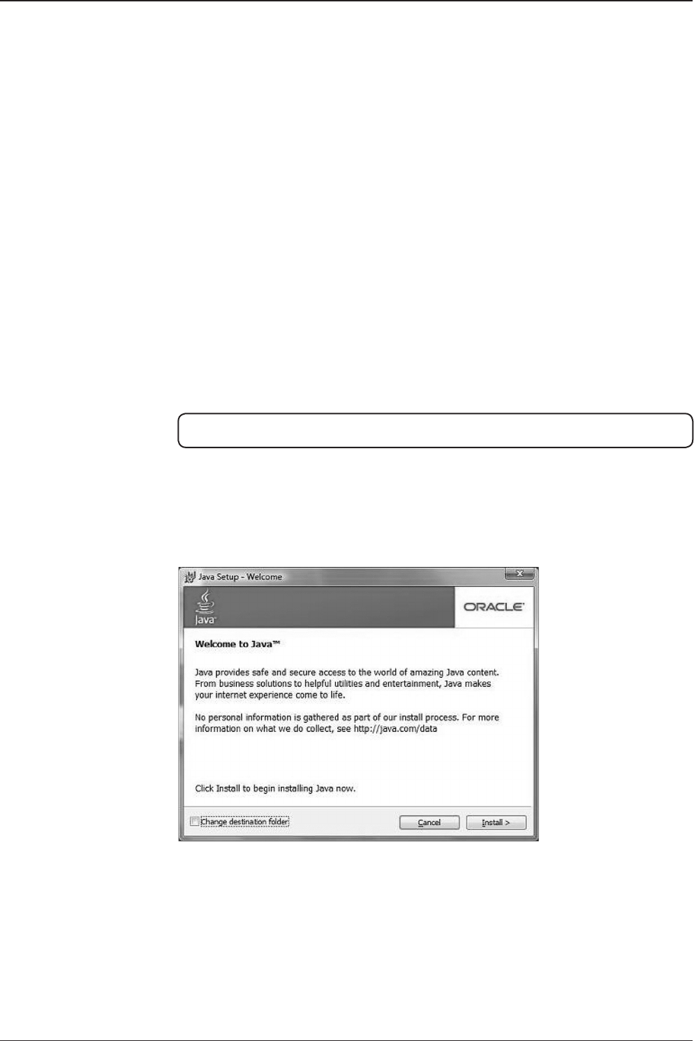
v240C – Marine Satellite Communication System
166
Method 2. Ofine method for downloading and installing
http://www.java.com/en/download/help/windows_ofine_download.xml
This process requires you to download an executable le that includes all the les
needed for the complete installation. You do not need to remain connected to the
Internet during the installation. The le can also be copied to a computer that is
not connected to the Internet.
1. Go to the Manual download page
2. Click on Windows Ofine.
3. The File Download dialog box appears prompting you to run or save the down-
load le. Click Save to download the le to your local system.
Tip: Save the le to a known location on your computer, for example, to your desktop.
4. Close all applications including the browser.
5. Double-click on the saved le to start the installation process.
6. The installation process starts. Click the Install button to accept the license
terms and to continue with the installation.
7. Oracle has partnered with companies that offer various products. The installer
may present you with option to install these programs when you install Java. After
ensuring that the desired programs are selected, click the Next button to continue
the installation.
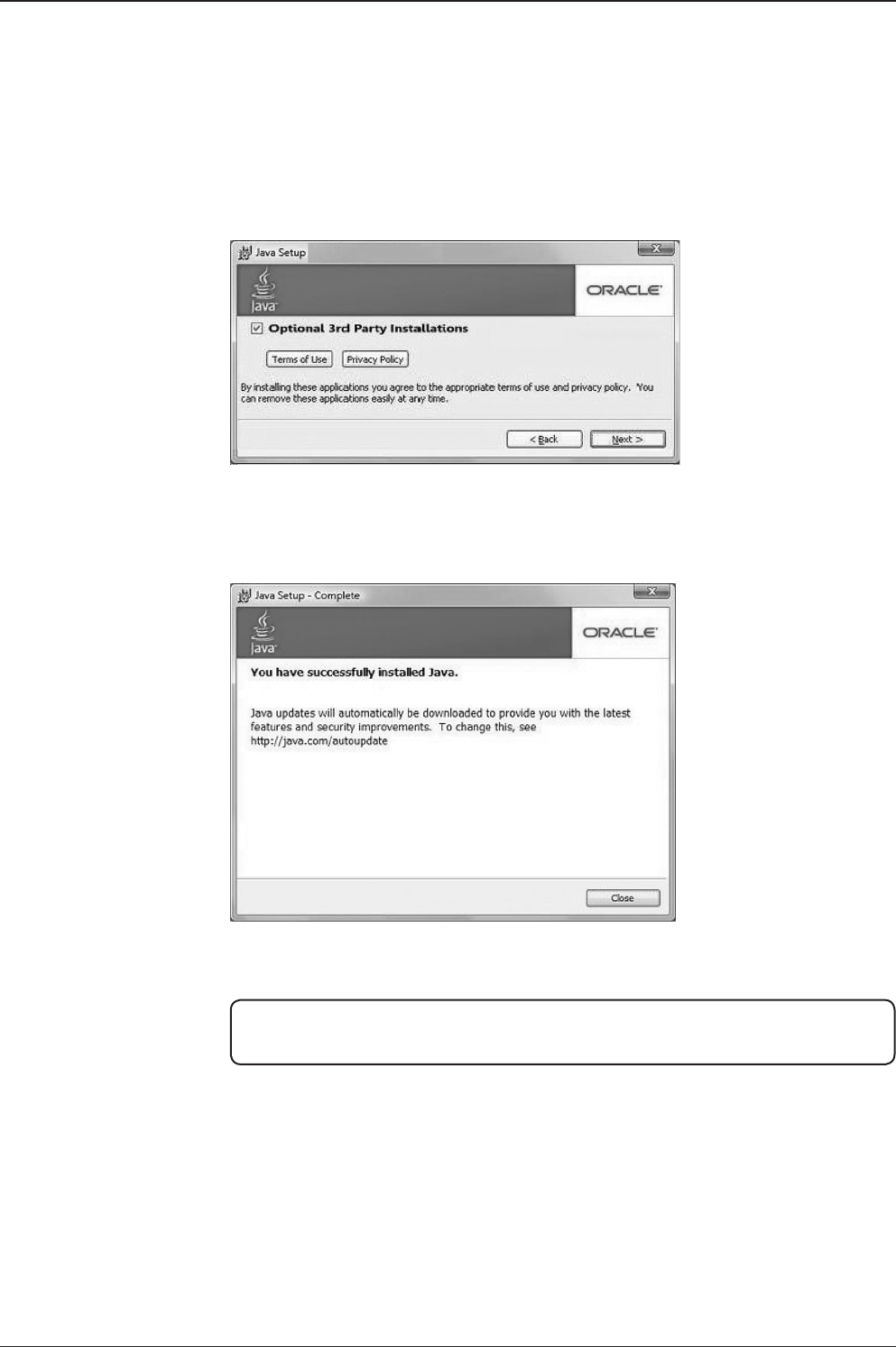
167
APPENDIX
8. A few brief dialogs conrm the last steps of the installation process: click Close
button on the last dialog.
9. This will complete Java installation process.
NOTE: You may need to restart (close and re-open) your browser to enable the java
installation in your browser.

v240C – Marine Satellite Communication System
168
1. After setting up the v240C that contains bluetooth functions and after authoriz-
ing the power supply, the antenna will conrm if it is operating normally.
2. In order to utilize the antenna's Bluetooth function,access to Aptus and click
"Use Bluetooth" button in the Antenna Basic Info section. The bluetooth module
will be enabled.
Appendix B: Setup Bluetooth Connection
TRACKING 116.0E KOREA3HN AGC:224 HL
AZ:201.4(201.4)EL:45.0 SK: -75.4 Fn

169
APPENDIX
3. Prepare a notebook that has a Bluetooth device included within it. While the
Bluetooth device is getting ready to be used you can choose to add a bluetooth
device if you right click on the Bluetooth icon.
*Methods of setting up Bluetooth within your notebook can differ by the
manufacturers software and Operating System being used within your notebook.
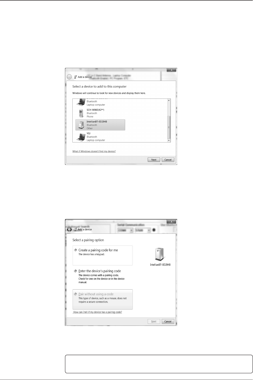
v240C – Marine Satellite Communication System
170
4. On the left is a window in order to run the setup wizard where you can add a
Bluetooth device. Find the IntellianBT-0D294B Bluetooth Device (0D294B may
be a different number depending on each user) and if you click next, then the
wizard will search for a Bluetooth device. The window for adding a bluetooth
device may differ by the type of Operating System being used.
5. Pair the device without using a code. Select "Pair without using a code" and
press Next.
NOTE: Some OS systems may not have an option to Pair the bluetooth device without
using a code therefore, go to the next step to enter a Pairing Code.
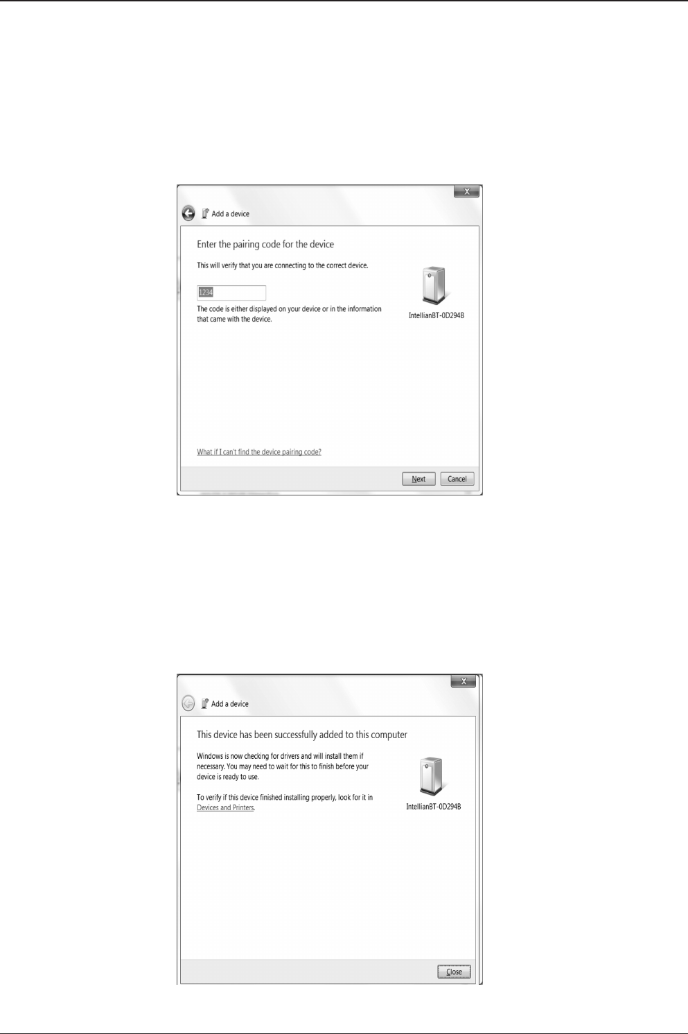
171
APPENDIX
6. The picture shown on the left is a Pairing Connection page. Enter the security
code in order to go to the next page. Do this by entering "1234" within the Secu-
rity Code box.
*In a case where the OS or the Bluetooth program has a Skip button available then instead of
entering a pairing code, press the Skip button to go onto the next page.
The Pairing Window may differ by different OS systems used. The picture on the left is in
Windows 7 format.
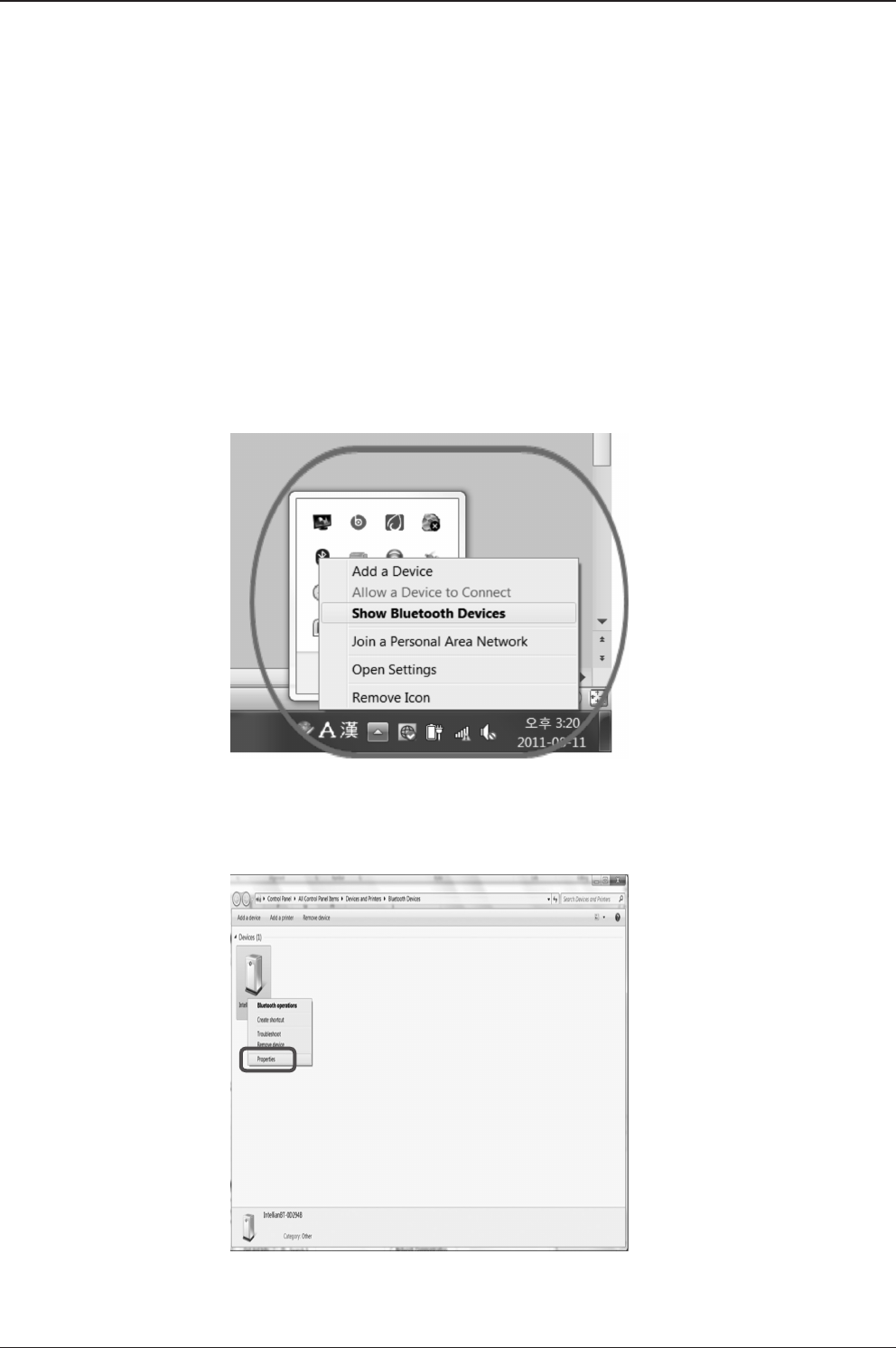
v240C – Marine Satellite Communication System
172
7. Pairing completed, the bluetooth device has been added to the computer.
Generic Serial Setup for OS systems that are different than Windows 7 If
instead you go to a Generic Serial Service page (which applies to some OS Sys-
tems), select the Generic Serial Service and click Next.
Click Finish to complete Bluetooth setup tasks.
8. Go to your toolbar and right click on your WiFi logo. Click on "Show Bluetooth
Devices" as shown in the picture on the left.
9. Right click on your bluetooth device called "IntellianBT-0D294B"
(name may differ by user) and click on "Properties".
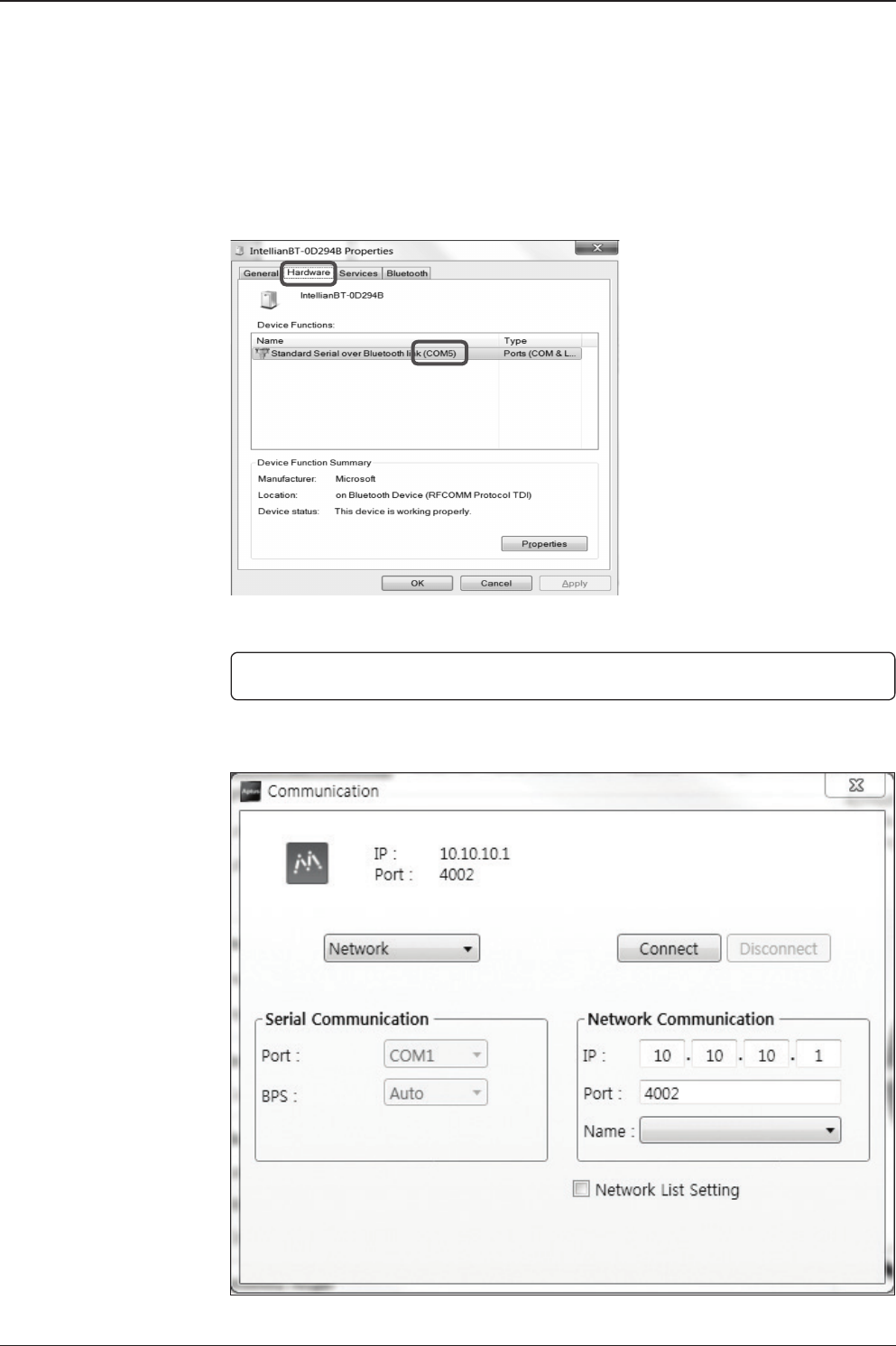
173
APPENDIX
10. Go to the Hardware tab and check your COM Port Number.
11. Excute the PC Program.
NOTE: Remember the COM Port Number for step 12.
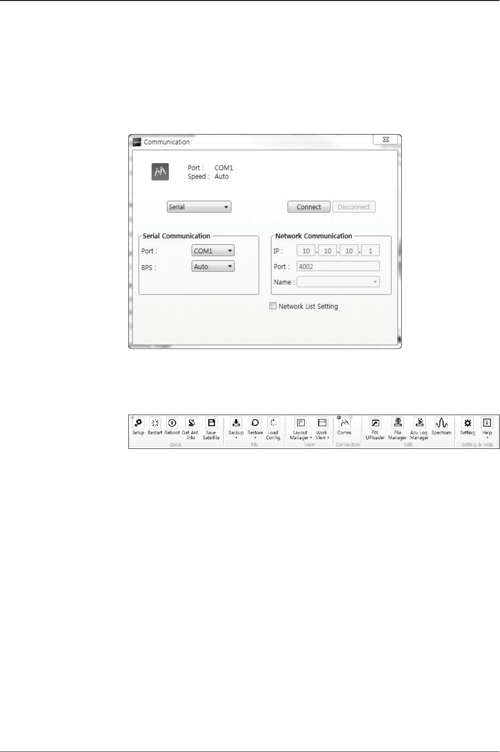
v240C – Marine Satellite Communication System
174
12. Assign the correct COM Port (step 10) and check the "Connect" box.
13. Press the "Get Ant. Info" button to conrm if the antenna's data within the PC
Program is functioning normally.
End of Bluetooth Setup (To Disconnect your Bluetooth, click the "Bluetooth"
button).

175
Technical Specication
Radome & Antenna Specication
Size Height 4.1m (161.4") (including base frame)
Diameter Ø3.3m (130")
Weight 670kg / 1477 lbs (Radome + Antenna + Base frame)
Radome Specication
Radome Material / Method FRP / Hand Layout
No. of Pieces
15EA
(Bottom 5, Top 5, Cap 1, Side Hatch 1, Botoom Hatch 2,
Base FRP 1)
Weight 120kg / 265 Ibs
RF Attenaution
0.5 dB Max. @ Tx Band
2.5 dB Max. @ Rx Band
* In Tx band Optimal condition. TBD
Radome Base Frame Specication
Size Height 30cm (11.8")
Diameter 185cm (72.8")
Base Frame Material / Method Steel / Welding
Weight 245kg / 551 Ibs
Antenna Assembly Specication
Diameter 2.4m (94.5")
Weight 305kg / 672 Ibs
Rx Frequency Standard : 3.625 GHz ~ 4.2 GHz
Gain 37.7 dBi @ 3.91GHz (with Radome)
Tx Frequency Standard : 5.85 GHz ~ 6.425 GHz
Gain 41.7 dBi @ 6.14GHz (with Radome)
Cross-pol isolation Minimum 35 dB
G / T 20.0 dB/K (Clear Sky, 20° Elevation)
Pedestal
Motion
Range
Azimuth Unlimited
Elevation -15° to +120°
Cross-level ±30°
Pointing Stabilization
Accuracy 0.2° peak mis-pointing @ max ship motion condition
Approvals
CE: conforms to EU Directive 89/336/EEC
FCC: veried to CFR47:Part 15
R&TTE
Power Consumption 100 ~ 240 V AC, 50 ~ 60Hz, 11A
Technical Specication

v240C – Marine Satellite Communication System
176
Rack Mount Antenna Control Unit
Display 2 Line 40 Character Graphic VFD Module
PC Interface RS232C (57600 bps 8, N, 1) / USB
Modem Interface Ethernet port / RS232C / I/O ports
RF Interface Antenna RX: N-Type, Modem RX: F-Type
Gyrocompass Interface NMEA 2000 / NMEA 0183
GPS Interface NMEA In / NMEA Out
Remote Access RJ45, TCP / IP
Power Consumption 100 ~ 240 V AC, 50 ~ 60Hz, 1A

177
Technical Specication
Warranty
This product is warranted by Intellian Technologies Inc., to be free from defects in
materials and workmanship for a period of THREE (3) YEARS on parts and TWO (2)
YEARS on labor performed at Intellian Technologies, Inc. service center from the
purchased date of the product.
Intellian Technologies, Inc. warranty does not apply to product that has been
damaged and subjected to accident, abuse, misuse, non-authorized modication,
incorrect and/ or non-authorized service, or to a product on which the serial number
has been altered, mutilated or removed.
It is required to present a copy of the purchase receipt issued by Intellian
Technologies, Inc. that indicates the date of purchase for after-sales service under
the warranty period. In case of failure to present the purchase receipt, the warranty
period will begin 30 days after the manufacturing production date of the product
purchased.
Any product which is proven to be defective in materials or workmanship, Intellian
Technologies, Inc. will (at its sole option) repair or replace during the warranty period
in accordance with this warranty. All products returned to Intellian Technologies, Inc.
under the warranty period must be accompanied by a return material authorization
(RMA) number issued by the dealer/distributor from Intellian Technologies, Inc. and
a copy of the purchase receipt as a proof of purchased date, prior to shipment.
Alternatively, you may bring the product to an authorized Intellian Technologies, Inc.
dealer/distributor for repair.
Additional Terms and Conditions;
The warranty(THREE (3) YEARS on parts and TWO (2) YEARS on labor) is effective only for products
purchased since January 1st, 2017.
