Intellifi SMRTSPT Smartspot User Manual PowerPoint Presentation
Intellifi BV Smartspot PowerPoint Presentation
Contents
- 1. Manual End User
- 2. Manual Installer
Manual Installer

5-3-2017 - Confidential 1
Intellifi Smartspot Professional Installation
Guide
Version 1.2
5-3-2017 - Confidential 2
Precautions
•Installation of this product must be performed by a
qualified installation partner
•This manual should not be distributed to end users
•When connecting an external antenna to your Smartspot,
take notice of the Approved Antennas section, see
appendices
•Do not expose the products to rain or moisture
•There are no user serviceable parts inside, refer all
servicing to qualified service personnel
Before you start
Note: before operation please take notice of the regulatory compliance statement and
the approved antennas section in order to make sure to comply to local regulations.

5-3-2017 - Confidential 3
Mounting
•A Smartspot Tile can easily be mounted in a dropped
ceiling, if it has a standard dimension of 595 mm.
•The Smartspots have a VESA mount hole pattern (100
mm), so standard VESA compatible mounting solutions
can be used.
•A Tile can also be suspended with cables. It is safe to drill
holes in the aluminium plate as long as you stay away
from the antennas. Please contact Intellifi first to discuss
your application.
•Do not expose the products to rain or moisture.
•For outdoor use, the Smartspot can be placed in a large
plastic box with an IP67 or better protection class. Please
contact Intellifi first to discuss your application.
1. Mounting antennas and Smartspots
In case you need support: contact your distributor or
Intellifi.
support@intellifi.nl
5-3-2017 - Confidential 4
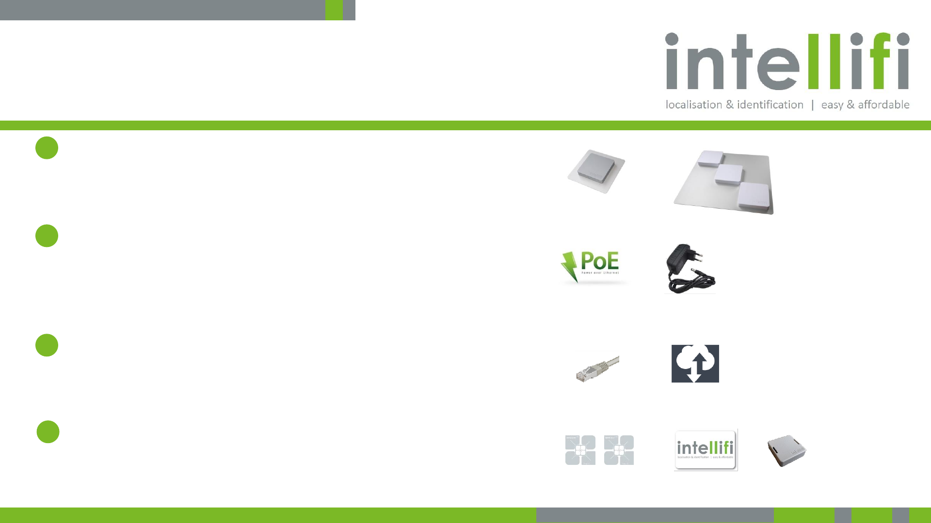
To get your Smartspot connected, you need power, Internet
connectivity and some tags
Intellifi Smartspot
•You may have a regular Smartspot, a Smartspot Tile, a
Smartspot multi-8 or a Smartspot BLE.
Power
•All Smartspots support Power over Ethernet (this is the
preferred way of powering) and come with an external
110V/230V power supply for convenience.
Internet connectivity
•Spots need Internet connectivity to connect to the cloud
Brain
Tags
•You’ll need a couple RFID tags or BLE tags to check that
things are running well.
2. Connecting | what you need
1
2
3
4
5-3-2017 - Confidential 5
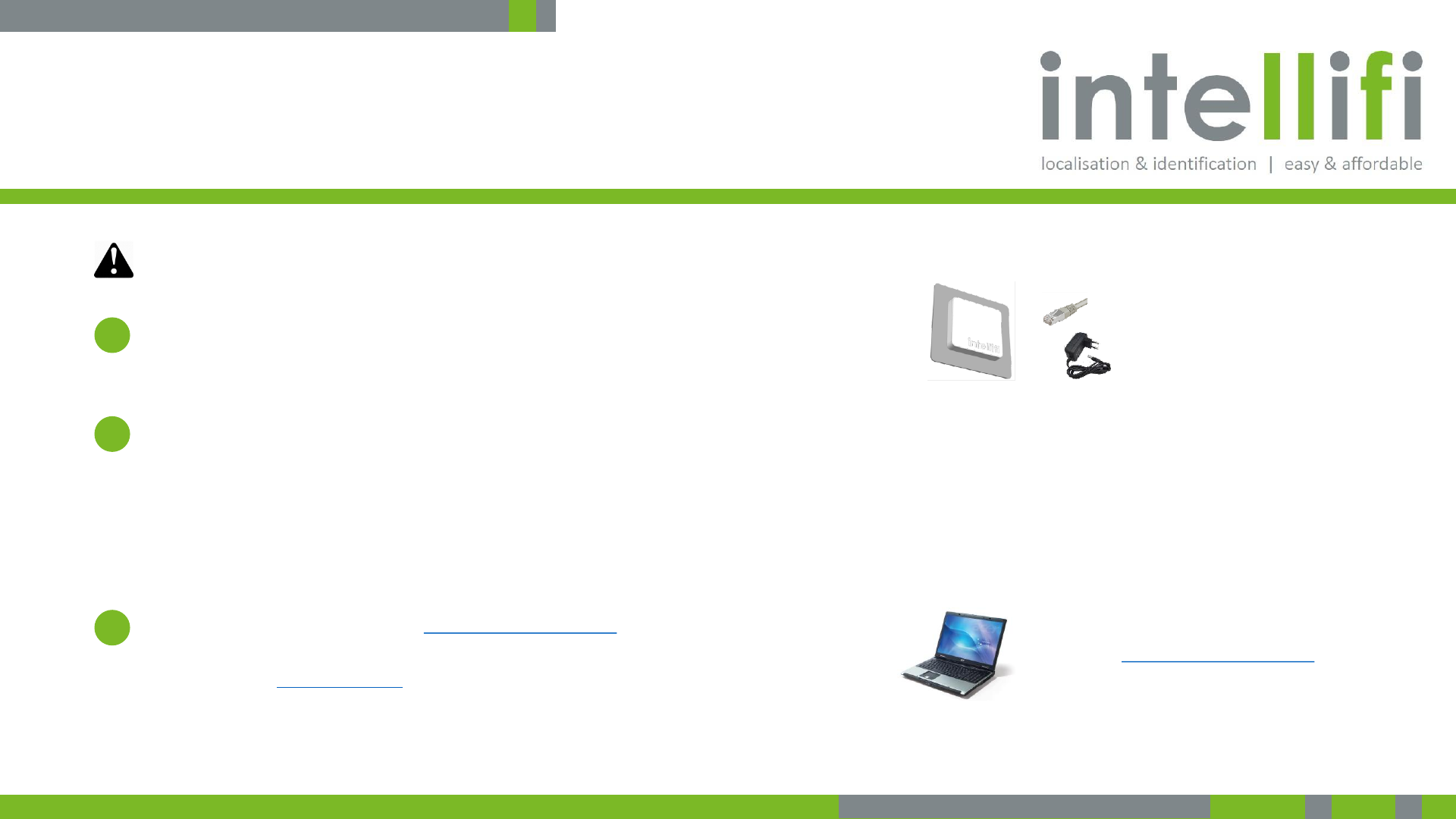
Connect and power the Smartspot according to the steps
below.
1. Connect the Ethernet port of the Intellifi Smartspot to an
Ethernet cable with Internet connectivity
2. Connect power to the smart spot using the power supply
•You may also provide power using Power over Ethernet (PoE) if
available.
•The Smartspots provide a short 3-tone beep during startup.
•Most likely a spot will immediately download the latest firmware and
restart again and there will be another 3-tone beep as confirmation.
3. Browse with a PC or tablet to https://brain.intellifi.nl
•Login with the demo account:
•Username: demo@Intellifi.nl
•Password: demo
2. Connecting | how to connect
Smartspot Ethernet to Internet
Access to information via
https://brain.intellifi.nl
Smartspot power (110-230AC)
1
2
3
Smartspot are plug and play
•Automatic IP configuration (DHCP)
•Automatic antenna detection at startup
•Automatic connect to the Cloud Brain
Note: before operation please take notice of the regulatory compliance statement and
the approved antennas section in order to make sure to comply to local regulations.
Consult the Smartsport User Quickstart Manual for more
information how to use the Smartspot and the web API

5-3-2017 - Confidential 6
FCC Compliance Statement
FCC compliance
This device complies with Part 15 of the FCC Rules. Operation is subject to the following two
conditions:
1. This device may not cause harmful interference, and
2. This device must accept any interference received, including interference that may
cause undesired operation.
This equipment has been tested and found to comply with the limits for a Class B digital device,
pursuant to Part 15 of the FCC Rules. These limits are designed to provide reasonable protection
against harmful interference in a residential installation. This equipment generates uses and can
radiate radio frequency energy and, if not installed and used in accordance with the instructions,
may cause harmful interference to radio communications. However, there is no guarantee that
interference will not occur in a particular installation. If this equipment does cause harmful
interference to radio or television reception, which can be determined by turning the equipment
off and on, the user is encouraged to try to correct the interference by one of the following
measures:
•Reorient or relocate the receiving antenna.
•Increase the separation between the equipment and receiver.
•Connect the equipment into an outlet on a circuit different from that to which the receiver is
connected.
•Consult the dealer or an experienced radio/TV technician for help.
Changes or modifications not expressly approved by the party responsible for compliance could
void the user’s authority to operate the equipment.
To comply with FCC RF radiation exposure limits for general population, the antenna(s) used for
this transmitter must be installed such that a minimum separation distance of 23 cm is
maintained between the radiator (antenna) and all persons at all times and must not be co-
located or operating in conjunction with any other antenna or transmitter.
3. Regulatory Compliance

5-3-2017 - Confidential 7
Industry Canada Compliance Statement
Industry Canada compliance
This Device complies with Industry Canada License-exempt RSS standard(s).
Operation is subject to the following two conditions:
1) this device may not cause interference, and
2) this device must accept any interference, including interference that may
cause undesired operation of the device.
Under Industry Canada regulations, this radio transmitter may only operate using
an antenna of a type and maximum (or lesser) gain approved for the transmitter
by Industry Canada. To reduce potential radio interference to other users, the
antenna type and its gain should be so chosen that the equivalent isotropically
radiated power (e.i.r.p.) is not more than that necessary for successful
communication.
This radio transmitter 22367-SMRTSPT has been approved by Industry Canada to
operate with the antenna types listed below with the maximum permissible gain
and required antenna impedance for each antenna type indicated. Antenna types
not included in this list, having a gain greater than 8.5 dBi, are strictly prohibited
for use with this device. The required antenna impedance is 50 ohms.
To comply with Industry Canada RF radiation exposure limits for general
population, the antenna(s) used for this transmitter must be installed such that a
minimum separation distance of 35 cm is maintained between the radiator
(antenna) and all persons at all times and must not be co-located or operating in
conjunction with any other antenna or transmitter.
Industrie Canada Conformité
Le présent appareil est conforme aux CNR d’Industrie Canada applicables aux
appareils radio exempts de licence. L’exploitation est autorisée aux deux
conditions suivantes :
1) l’appareil ne doit pas produire de brouillage;
2) l’appareil doit accepter tout brouillage radioélectrique subi, même si le
brouillage est susceptible d’en compromettre le fonctionnement.
Afin de réduire le risque d’interférence avec d’autres utilisateurs, le type
d’antenne et son gain doivent être choisis de telle sorte que la puissance isotrope
rayonnée équivalente (PIRE) ne soit pas supérieure à celle permise pour une
communication réussie.
Cet appareil a été conçu pour fonctionner avec l’antenne (s) énumérées à la
section suivante qui ont un gain maximum de 8.5 dB. Antennes pas inclus dans
cette liste ou présentant un gain supérieur à 8.5 dB sont strictement interdits
pour utilisation avec cet appareil. L’impédance d’antenne requise est de 50 ohms.
La ou les antennes doivent être installées de telle façon qu’une distance de
séparation minimum de 35 cm soit maintenue entre le radiateur (antenne) et
toute personne à tout moment. Cet appareil et son antenne (s) ne doit pas être
co-localisés ou fonctionnement en association avec une autre antenne ou
transmetteur.
3. Regulatory Compliance

5-3-2017 - Confidential 8
Approved Antennas
The Smartspots are certified with these 3 antennas. For the use of other
antennas see next page.
Connected antennas are detected automatically, no software settings needed.
Note: the API has a possibility to disable connected antennas, please consult the
web API documentation.
Option 1:
Model Spot Antenna (A14)
Manufacturer Intellifi
Antenna Description Patch Antenna
Polarization dual linear
Frequency range 860 – 930 MHz
Impedance 50 Ohm
Return Loss > 10 dB
Gain 8.5 dBi
Option 2/FCC:
Model Micro Antenna 915 MHz (A75)
Manufacturer Intellifi
Antenna Description Ceramic Patch Antenna
Polarization RHCP
Frequency range 902 – 928 MHz
Impedance 50 Ohm
Gain 4 dBic
Option 2/ETSI:
Model Micro Antenna 866 MHz (A74)
Manufacturer Intellifi
Antenna Description Ceramic Patch Antenna
Polarization RHCP
Frequency range 864 – 868 MHz
Impedance 50 Ohm
Gain 4 dBic
Option 3:
Model Shelf Antenna (A84)
Manufacturer Intellifi
Antenna Description Patch Antenna (2 pcs)
Polarization dual linear
Frequency range 860 – 930 MHz
Impedance 50 Ohm
Gain 7 dBi
4. Approved Antennas

5-3-2017 - Confidential 9
Other Antennas
When connecting other antennas, make sure the
effective radiated power PEIRP is within regulatory
limits. This may require reduction of the output
power.
•For the USA and Canada it is PEIRP = 36 dBm
•For the ETSI region it is PEIRP = 35.15 dBm
•PEIRP = Reader power – multiplexer loss – cable loss + antenna gain
Note:
•Multiplexer loss = 1 dB, except for the Multi-16 where it is 2 dB
•Intellifi supplied coax cable LMR195 has a loss of 0.37 dB per meter
•Intellifi supplied coax cable LMR240 has a loss of 0.25 dB per meter
•LMR240 cable is less flexible than LMR195.
If you need assistance in calculating cable losses or
maximum power settings, please contact your
distributor or support@intellifi.nl
Example 1:
You have a 6 dBic antenna. You want to connect it to a Smartspot Multi-8 using a
with 4 meter of LMR195 cable.
When you set the output power to 27 dBm (the recommended value for best
performance), the PEIRP = 27 – 1 – 4*0.37 + 6 = 30.52 dBm
This leaves you with enough margin to satisfy the ETSI, FCC and IC regulations.
Example 2:
You have a high gain antenna with a gain of 12 dBi and you use a cable of 1 meter
LMR195.
Now PEIRP = 27 – 1 – 0.37 + 12 = 37.63 dBm. This exceeds the legal limits and the
power must be reduced in order to comply with the regulations.
For FCC/IC, the power setting must be reduced by 2 dB (whole steps only),
for ETSI it must be reduced by 3 dB.
4. Other Antennas