Intelligent Automation orporated GUARDIAN ARGUS Guardian is a fence-mounted, RF-based perimeter intrusion detection system. This system uses a network of unattended wireless sensors to create a wireless trip wire along a perimeter to provide early warnings against intrusions. User Manual
Intelligent Automation, Incorporated ARGUS Guardian is a fence-mounted, RF-based perimeter intrusion detection system. This system uses a network of unattended wireless sensors to create a wireless trip wire along a perimeter to provide early warnings against intrusions.
User Manual

Protected under U.S. patent number 8,232,878
© 2018 Intelligent Automation, Inc. | 15400 Calhoun Drive, Suite 190, Rockville, MD 20855 | Phone: 301 294 5200 | Fax: 301 294 5201
Revision A August 2018
ARGUS GUARDIAN

Page | 1
© 2018 Intelligent Automation, Inc.
Table of Contents
1 Notes ..................................................................................................................................................... 2
2 Quick Start Guide .................................................................................................................................. 2
3 Hardware Overview .............................................................................................................................. 7
3.1 Hardware Kit Description .............................................................................................................. 7
3.2 Node Description .......................................................................................................................... 8
3.3 Node Mounts ................................................................................................................................ 8
3.4 Battery Replacement .................................................................................................................... 8
4 Software Overview .............................................................................................................................. 10
4.1 Initial Setup Wizard ..................................................................................................................... 10
4.2 User Interface Overview ............................................................................................................. 11
4.2.1 Main Toolbar ....................................................................................................................... 11
4.2.2 GUI Panels ........................................................................................................................... 11
4.3 Configuration Wizard .................................................................................................................. 13
4.4 Configuration and Active Modes ................................................................................................ 14
4.5 Node Positioning ......................................................................................................................... 15
4.5.1 Drag-and-Drop Node Positioning ........................................................................................ 15
4.5.2 Manual Lat/Long Node Positioning ..................................................................................... 15
4.5.3 GPS Node Positioning .......................................................................................................... 15
4.6 Link Configuration ....................................................................................................................... 16
4.6.1 Link Configuration Window ................................................................................................ 16
4.6.2 Link Configuration Toolbar .................................................................................................. 17
4.7 Link Metrics Mode ...................................................................................................................... 20
4.7.1 Link Metrics Guidelines ....................................................................................................... 20
4.8 Alerts ........................................................................................................................................... 20
4.8.1 Alert Log Files ...................................................................................................................... 21
4.9 Plug-in Configuration .................................................................................................................. 22
4.9.1 Camera Plug-in .................................................................................................................... 22
4.9.2 Text Message Plug-in .......................................................................................................... 23
5 System Shutdown ............................................................................................................................... 26
6 Node Deployment Guide .................................................................................................................... 27
7 Troubleshooting .................................................................................................................................. 29
Page | 2
© 2018 Intelligent Automation, Inc.
1 Notes
“Changes or modifications not expressly approved by the manufacturer could void the user’s authority
to operate the equipment”
2 Quick Start Guide
This Quick Start section of the user manual presents the basics of getting an ARGUS Guardian
deployment up and running. For more details on each topic, refer to the later sections in this manual.
Step 1: Turn on the laptop PC
Note that if the laptop is locked, the default username is ‘ARGUS’ and the password is ‘iai’
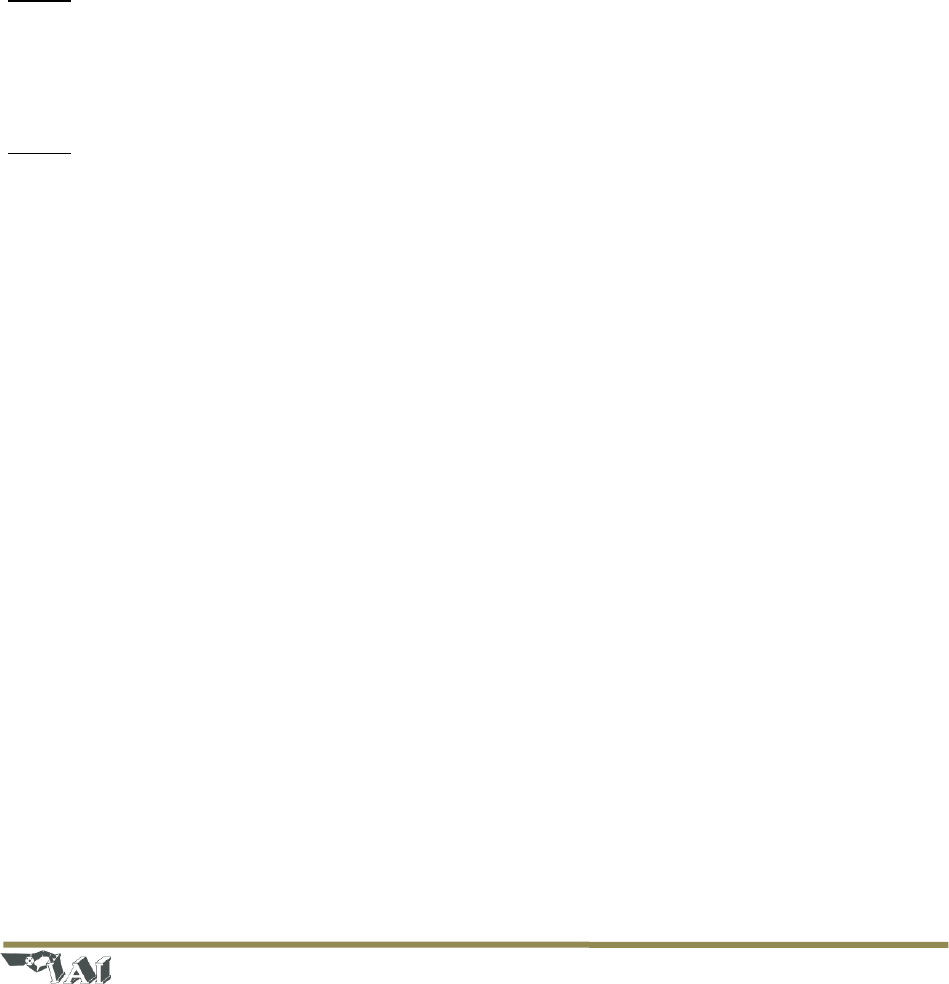
Step 2: Connect the Gateway node and turn it on
The ‘Gateway Node’ enables communication between the ARGUS GUARDIAN nodes and the laptop PC.
The Gateway node connects to the PC via a short USB cable, and uses a 2.4GHz antenna with a standard
RP-TNC connector) to communicate with the ARGUS GUARDIAN network.
- Attach an antenna to the port on the top of the Gateway node.
- Connect the included USB cable to the rugged connector on Gateway Node and plug the other
end into one of the USB ports on the right side of the laptop (see Figure 1). Be sure to use the
same USB port each time you connect the Gateway Node, as the software is configured to look
for it on the same port each time. The gateway will power on as soon as it is connected to the
USB port.
- Attach the external 2.4GHz antenna to the Gateway Node. Optional: Connect an RF extension
cable and outdoor rated antenna to position the antenna outside of a building or on a rooftop.
For antenna coax cable runs greater than 10ft, use an RF amplifier (contact IAI for details).
Page | 3
© 2018 Intelligent Automation, Inc.
Figure 1: ARGUS GUARDIAN Gateway connection to PC
Step 3: Start the ARGUS GUARDIAN software
To start the ARGUS GUARDIAN software, click the ‘ARGUS GUARDIAN’ software icon on the desktop. The
splash screen for the ARGUS GUARDIAN View application should appear, then after a few seconds, the
main graphical user interface (GUI) should appear. For a full description of the GUI, modes, buttons, etc.
see Section 0.
Figure 2: GUI software (right)
Step 4: Create a new ARGUS GUARDIAN configuration
Prior to operating the ARGUS GUARDIAN system, it must be configured by defining the node locations
and active fence links to monitor.
- Press the ‘Configure’ button in the upper left corner of the screen.
- Select ‘New’ as the Configuration Type and click ‘Next’.
Page | 4
© 2018 Intelligent Automation, Inc.
- Specify a configuration description (optional) and select a Map Type: None, Satellite, or User
Defined (see Section 4.3 for descriptions). Click ‘Next’.
- Click ‘Next’ to leave Camera Monitoring disabled (see Section 4.9.1 for details).
- Click ‘Finish’ to leave SMS/MMS Notifications disabled (see Section 4.9.2 for details).
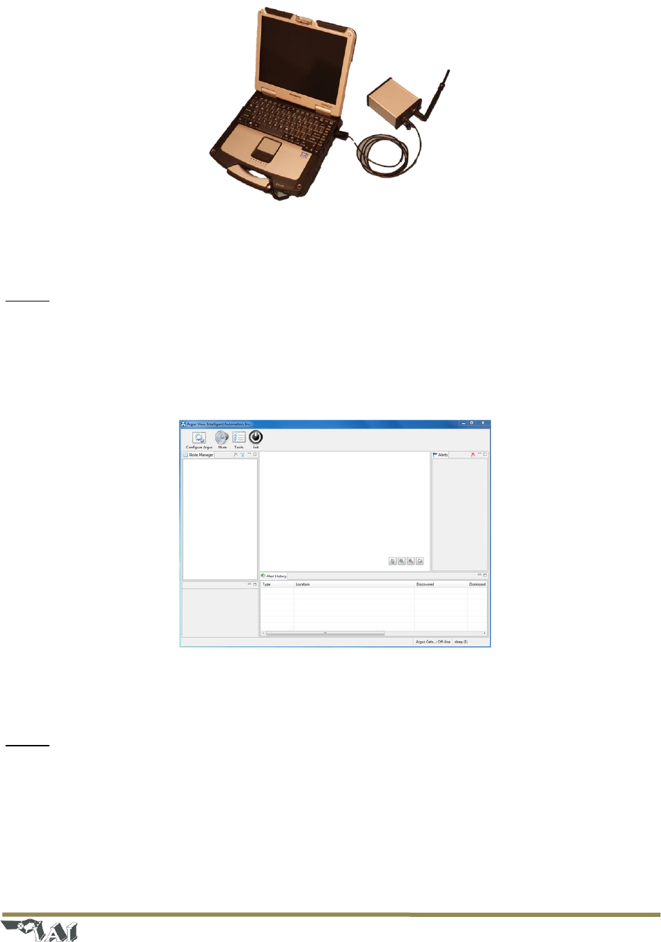
- The new configuration has been created, and you are now in Configuration Mode. The main GUI
should again be displayed (see Figure 3).
Figure 3: Initial Configuration Mode view (with satellite map type selected)
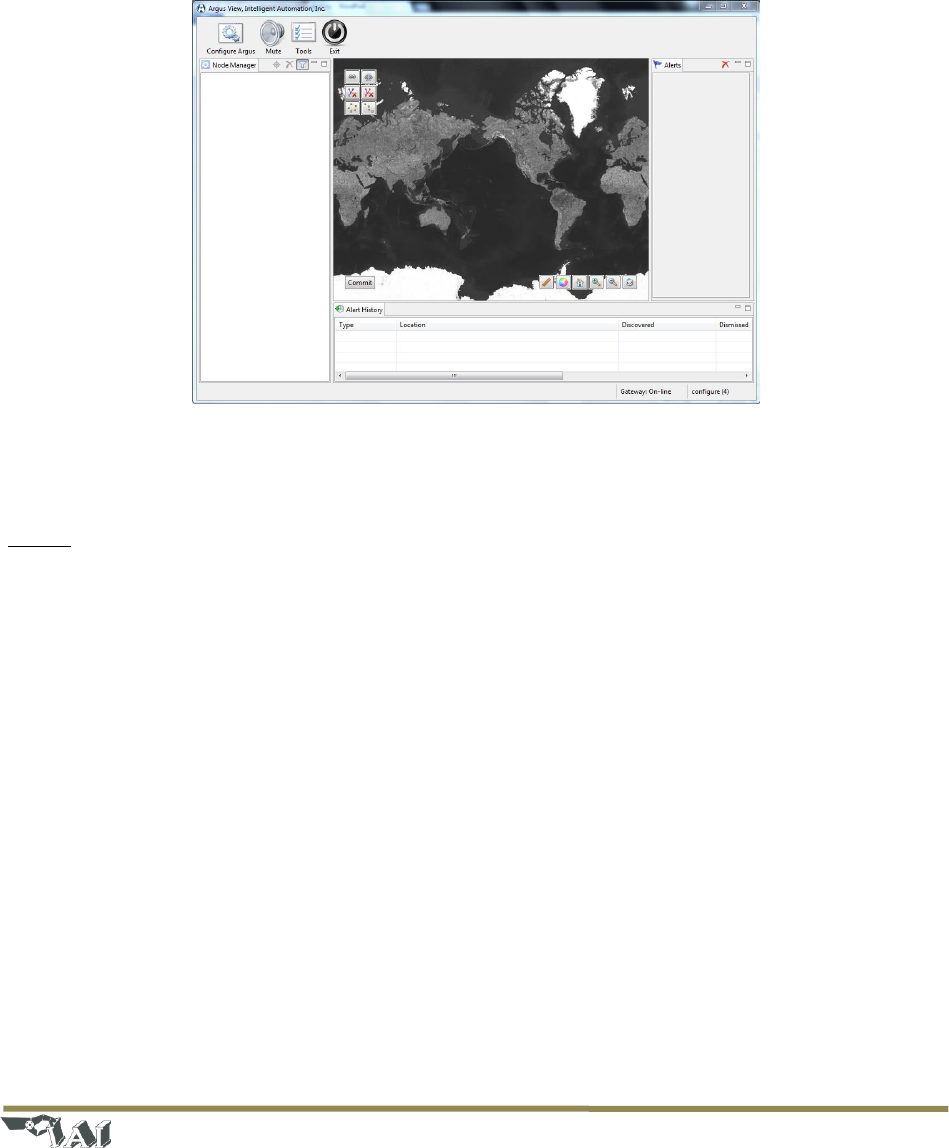
Step 5: Turn on fence nodes
Attach antennas to and turn on at least two ARGUS GUARDIAN fence nodes. They will automatically
register with the system and appear in the ‘Node Manager’ list on the left side of the screen. The nodes
will appear on the screen with the identification number corresponding to the node ID number on the
back of each ARGUS GUARDIAN unit. See Section 4.2.2 for detailed descriptions of the icons that are
shown in the Node Manager.
Page | 5
© 2018 Intelligent Automation, Inc.
Figure 4: Configuration Mode with two ARGUS GUARDIAN nodes turned on
Step 6: Position nodes on the on-screen map
Pan and zoom to the desired area of the on-screen map. Drag the nodes from the Node Manager list
directly onto the map or click-and-drag the nodes around on the map as desired. See Section 4.5 for full
details regarding placement on nodes on the map.
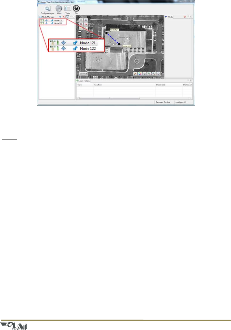
Step 7: Enable fence links
Click on a link to display the link details window, in which you may specify a link description (optional)
and set the link as either ‘Active’ (actively monitored by the software) or ‘Inactive’ (ignored by the
monitoring software). Active links are indicated in the Map View by solid yellow lines and Inactive links
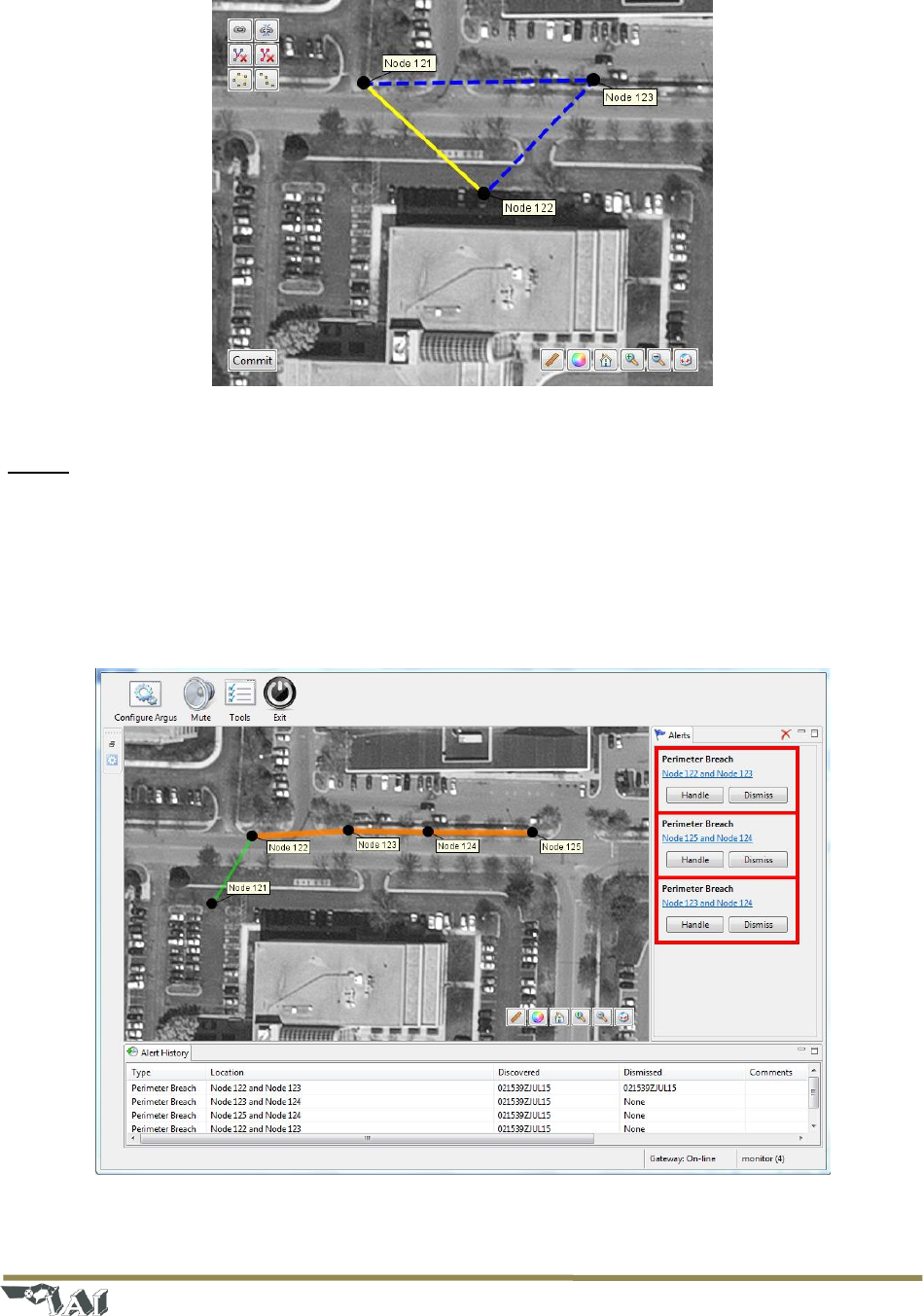
are indicated by dotted blue lines. See Figure 5 for an example configuration with three nodes, one
active link, and two inactive links. See Section 4.6 for full details regarding link configuration.
Page | 6
© 2018 Intelligent Automation, Inc.
Figure 5: Map view of three node configuration with one Active link (yellow line) and two Inactive links (blue dotted lines)
Step 8: ‘Commit’ the configuration
Press the ‘Commit’ button in the lower left corner of the Map View to save the ARGUS GUARDIAN
configuration and place the system into Active Mode. The system will now be continuously monitoring
and logging any fence link triggers, displaying alerts both within the Map View and in the Alerts panel on
the right side of the GUI. See sample screenshot in Figure 6, and refer to Section 4.8 for more details
regarding the alerts.
Figure 6: ARGUS GUARDIAN GUI in Active Mode. Alerts are shown in the right panel; Alert History is shown in the bottom
panel, and current status is shown in the center Map View.

Page | 7
© 2018 Intelligent Automation, Inc.
3 Hardware Overview
3.1 Hardware Kit Description
The ARGUS GUARDIAN Hardware Kit includes everything required for a deployment of the ARGUS
GUARDIAN system, all contained within a single portable case (~50lb weight). The typical kit includes:
- 9 ARGUS GUARDIAN sensor nodes and 1 Gateway node and antennas
- Rugged laptop with ARGUS GUARDIAN software installed
- User manual
Page | 8
© 2018 Intelligent Automation, Inc.
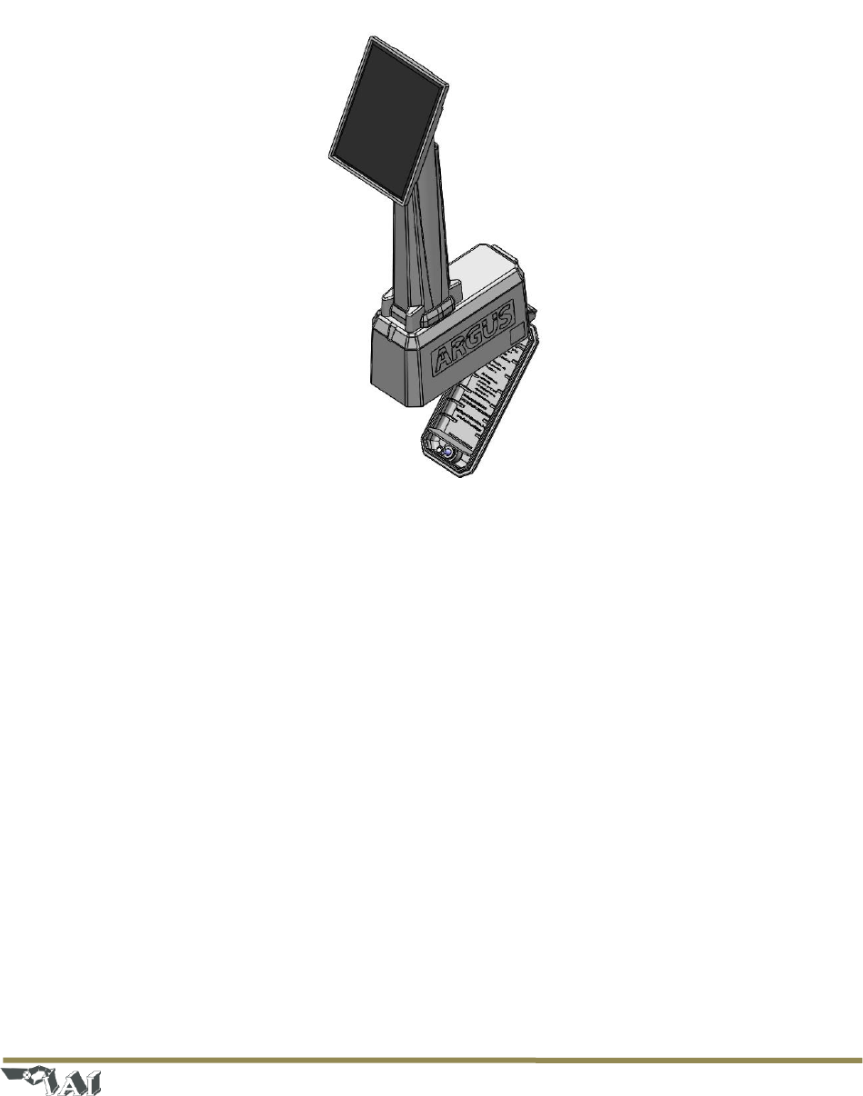
3.2 Node Description
The ARGUS GUARDIAN node is a small, rugged device intended for long-term unattended outdoor use. It
is solar cell powered with a backup battery.The Guardian is intended to be fence mounted. The node’s
interface is intentionally very simple (see Figure 7).
Figure 7: Front side of the ARGUS GUARDIAN node
The node interface includes:
- .
- Tripod Mount – Each node includes a standard ¼”-20 threaded insert in the bottom for
mounting the node. See Section 3.3 for details on mounting methods.
- Battery Door – The bottom of the node includes a battery door with a tamper-proof hex nut for
accessing the battery. See Section 3.4 for details on battery replacement.
3.3 Node Mounts
The ARGUS GUARDIAN nodes include a custom metal bracket, so they will mount on Ameristar fences.
3.4 Battery Replacement
Each ARGUS GUARDIAN Node uses 1x UB4.5-4k universal battery. To change the battery, simply remove
the battery cover on the bottom of the unit by rotating the fastener 90 degrees counter-clockwise.

Page | 9
© 2018 Intelligent Automation, Inc.
Replace the battery (observing the correct polarity), close the cover, and secure the fastener (note that
you may need to firmly press the back cover to enable the fastener to latch).
Page | 10
© 2018 Intelligent Automation, Inc.
4 Software Overview
The proper install location for ARGUS GUARDIAN is C:\ARGUS GUARDIAN, where you can find the
application, logs, and configuration files.
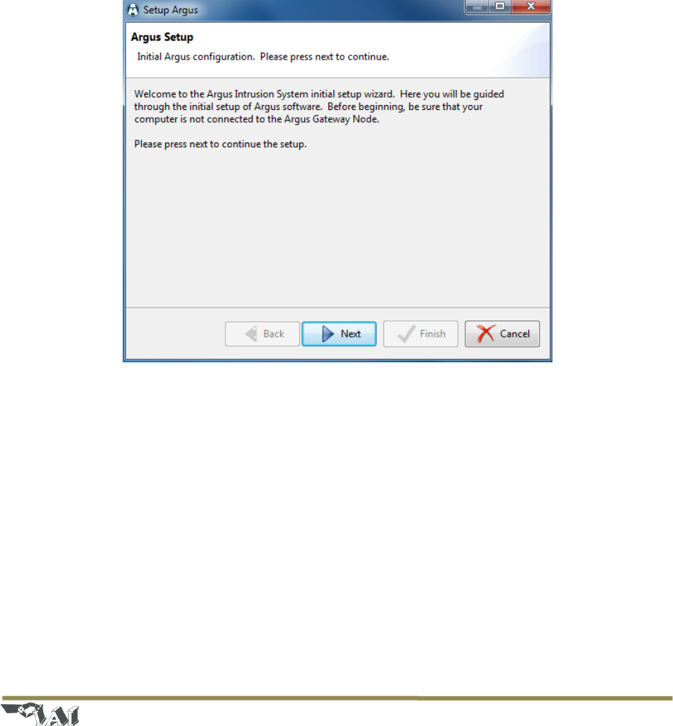
4.1 Initial Setup Wizard
When the software is run for the first time on a new machine, it will automatically start the Initial Setup
Wizard upon startup (see Figure 8). Once the Initial Setup Wizard has been completed for a particular
Gateway node, it will not need to run again. The primary purpose of the Initial Setup Wizard is to
establish which serial port is used to communicate with the Gateway node. Carefully follow the on-
screen instructions to enable the software to automatically identify the correct port.
Figure 8: ARGUS GUARDIAN software Initial Setup Wizard
If the Gateway node is changed for some reason, the Initial Setup Wizard will need to be run again so
that the software can be configured to use the correct serial port. To trigger the Initial Setup Wizard to
run again, close the ARGUS GUARDIAN software and run the ‘reset-settings’ script in the installation
directory. Restart the ARGUS GUARDIAN software, and the Initial Setup Wizard should run again.
Page | 11
© 2018 Intelligent Automation, Inc.
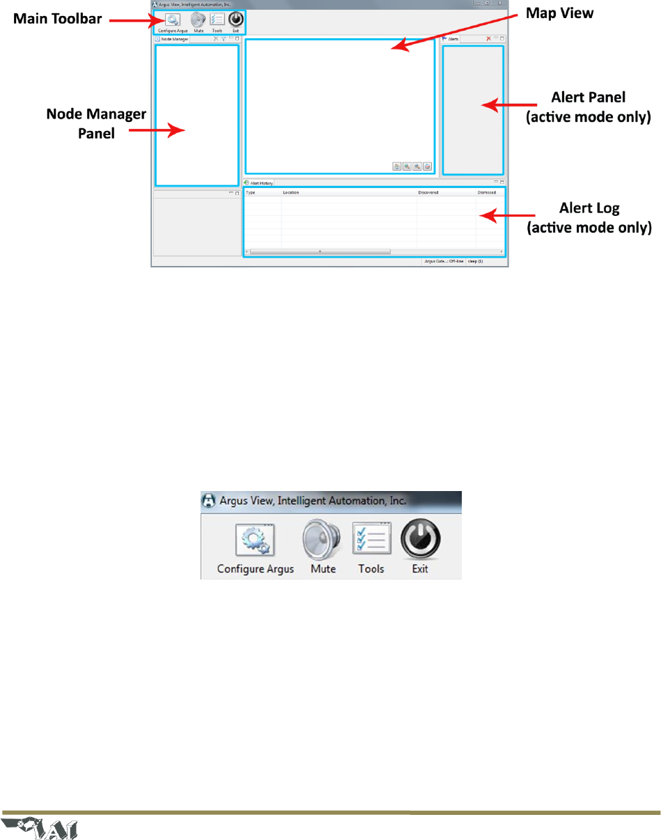
4.2 User Interface Overview
Upon starting the ARGUS GUARDIAN software, the user will be presented with the main Graphical User
Interface (see Figure 9). This section presents an overview of the interface before diving into the
operational details in subsequent sections.
Figure 9: Main Graphical User Interface (GUI) layout
4.2.1 Main Toolbar
The main toolbar is located at the top left corner of the GUI. The toolbar includes five buttons:
- Configure – Launch the Configuration Wizard (see Section 4.3)
- Mute – Enable/disable the audible alarm when an alert is received from the ARGUS GUARDIAN
hardware
- Tools – Enter the admin utility (not described in this manual)
- Exit – Close the ARGUS GUARDIAN View software
Figure 10: Main Toolbar
4.2.2 GUI Panels
The GUI consists of several panels with various functions:
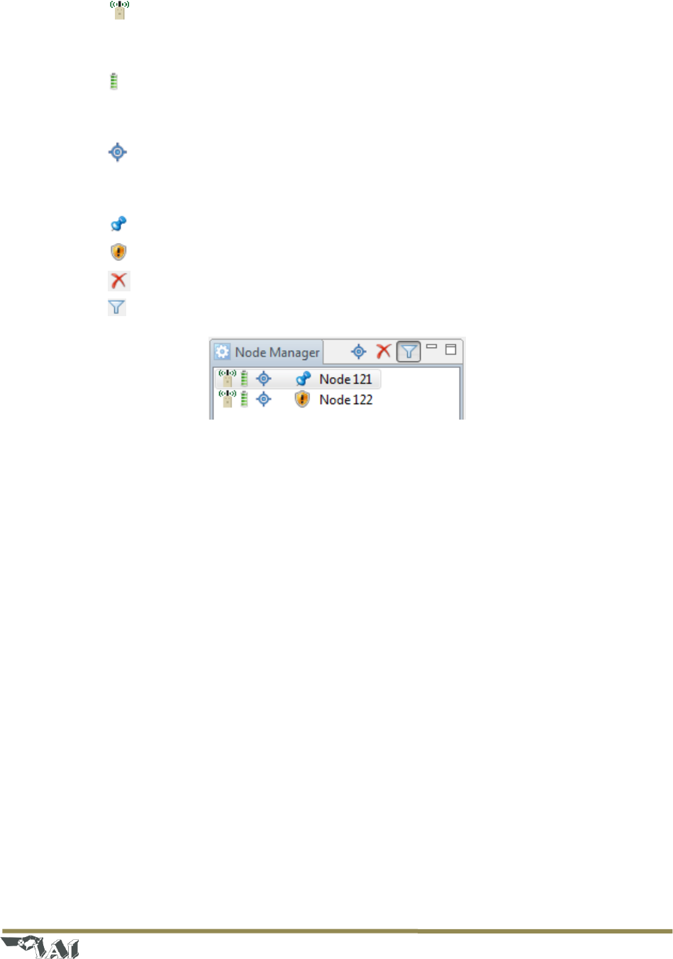
- Node Manager Panel – This panel includes a list of ARGUS GUARDIAN nodes and their status
(see Figure 11). Each row in the list indicates the state of one node in the system, including
battery status and GPS status.
Page | 12
© 2018 Intelligent Automation, Inc.
o The radio icon indicates an active ARGUS GUARDIAN fence node – future versions of
the system may have different types of nodes, which will be indicated by different icons
in the leftmost location.
o The battery icon indicates the battery status of the node. If the icon has a small red ‘x’
on it, this indicates that the node is ‘dead’ (i.e., it has not checked in for some time, or it
is turned off).
o The presence of the third icon (a small satellite) indicates that a valid GPS fix has
been received from the node. See Section 4.5.3 for more information regarding GPS
node positions.
o The pin indicates that the node has been placed on the map.
o The shield icon indicates that a node is unpinned.
o The delete icon hides a node from the Node Manager view.
o Clicking on the filter icon makes hidden nodes reappear.
Figure 11: Node Manager Panel
- Map View – This is the central panel in the GUI, and shows the location and status of all of the
nodes and the links between the nodes. This area may use satellite imagery or a user-supplied
image as the background for the view. Depending on the current mode (Configuration or Active)
some buttons may or may not be displayed within the Map View.
o In Configuration Mode, the Link Configuration Toolbar is shown in the upper left corner
(see Section 4.6.2 for details regarding this toolbar) and the ‘Commit’ button is shown in
the lower left corner.
o In both modes, the View Control Toolbar is displayed in the lower right corner of the
Map View (see Figure 12). This toolbar includes several buttons for manipulating the
Map View.
Measure – In satellite view, measure between two points by clicking to select a
starting point and moving the mouse to the second point. Right click to reset the
starting point.
Color/grayscale – Switch the satellite view between color and grayscale
Home – Pan/zoom the view to put all nodes within the view window
Zoom in/Zoom out
Link metrics– Displays received signal strength indicator (RSSI) and packet
reception rate (PRR) for the active fence links. See section 3.7 for details.
Page | 13
© 2018 Intelligent Automation, Inc.
Figure 12: View Control Toolbar
- Alert Panel – This is the panel in which alert messages are displayed when in Active Mode (see
Section 4.8).
- Alert Log – This panel shows a log of all past alerts.
4.3 Configuration Wizard
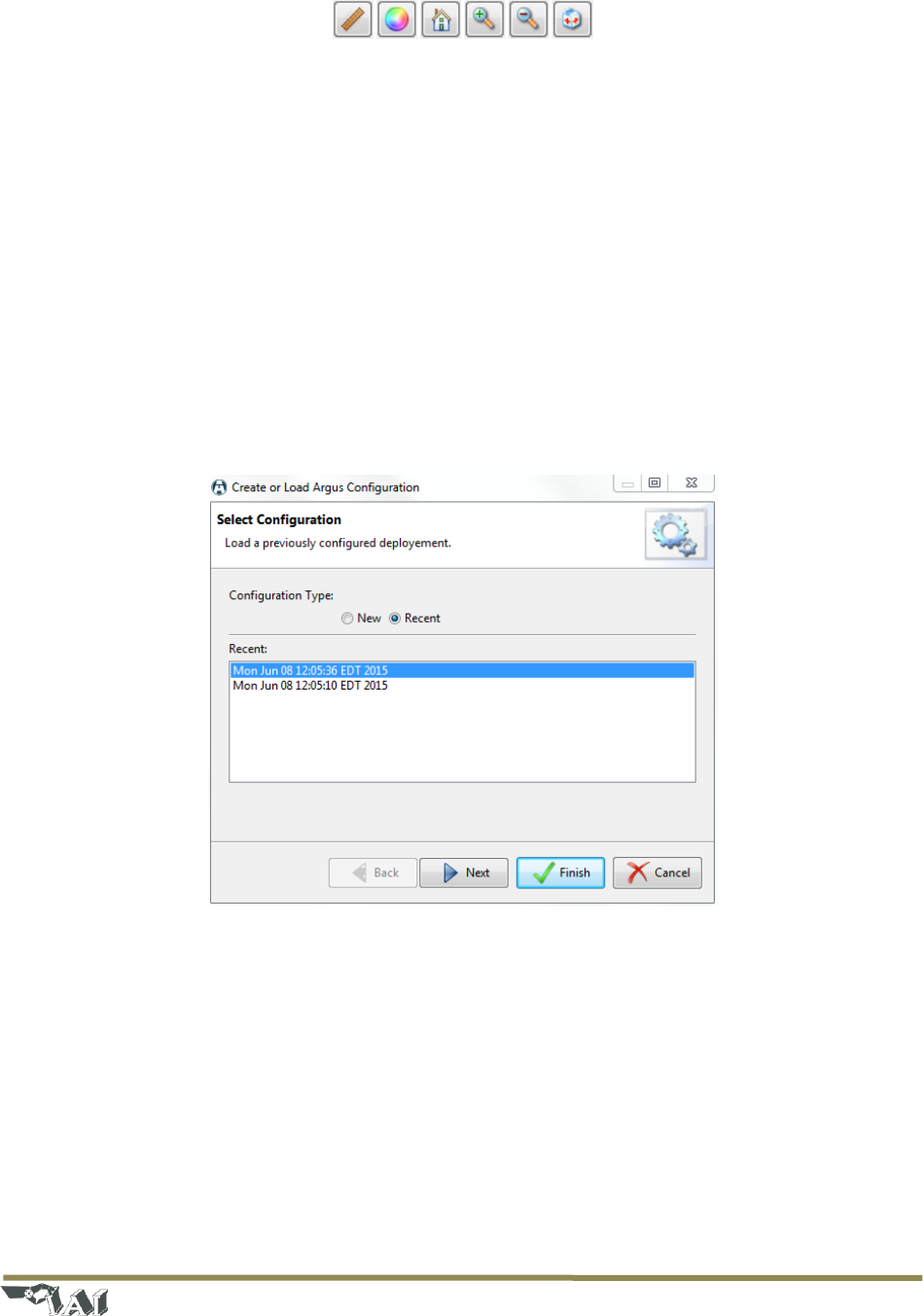
After starting the ARGUS GUARDIAN software, a configuration will need to be loaded into the system. To
start the configuration process, press the ‘Configure’ button in the upper left corner of the GUI. This will
launch the Configuration Wizard (see Figure 13). Either a new configuration can be created, or an
existing configuration can be loaded. To start a new configuration, select the ‘New’ radio button and
press ‘Next’. To reload an existing configuration, select the ‘Recent’ radio button, select the desired
configuration by date/time/description, and press ‘Finish’ (in which case the wizard will exit, the existing
configuration will be loaded, and Configuration Mode will be entered immediately).
Figure 13: Configuration Wizard – Initial page
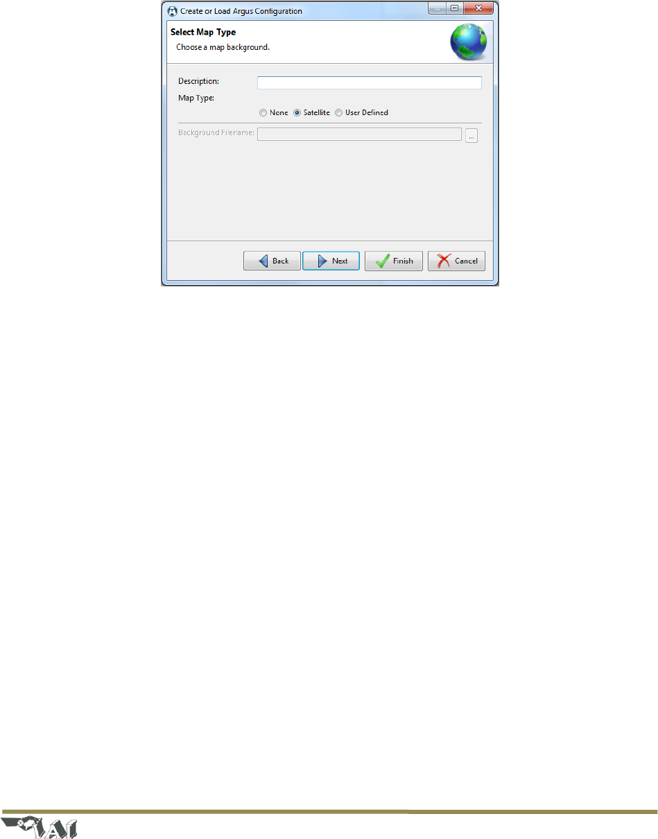
If a new configuration was selected, then the next page in the Configuration Wizard is the ‘Select Map
Type’ page (see Figure 14). A description may be entered for the configuration (optional) and the map
type can be specified. There are three different map types that may be selected:
- None – No map is used (white background)
- Satellite – Satellite imagery from an online resource is used. To view map locations and/or zoom
levels that have not been previously viewed, an active Internet connection will be required to
download map tiles. Map tiles are cached locally, so if a particular area and zoom level have
already been viewed, then the connection to the Internet is not required.
Page | 14
© 2018 Intelligent Automation, Inc.
- User Defined – A user provided image can be used as the background for the configuration. This
may be useful if, for example, the area of interest is around an object such as a helicopter.
Referencing the deployment to an image of a helicopter may be more intuitive than referencing
it to a map.
Figure 14: Configuration Wizard – Map Type selection
After clicking ‘Next’, other wizard pages may be presented, depending on the plug-ins included with the
particular distribution of the ARGUS GUARDIAN software being run. See Section 4.9 for information on
configuring each of the available plug-ins.
4.4 Configuration and Active Modes
There are two main modes of operation for the ARGUS GUARDIAN control software: Configuration
Mode and Active Mode.
Configuration Mode is the initial state that is entered when creating a new configuration or reloading a
preexisting configuration. In this mode, nodes can be repositioned (see Section 4.5) and links can be
made active/inactive (see Section 4.6). Alerts are not issued in Configuration Mode. Pressing the
‘Commit’ button in the lower left corner of the Map View saves the configuration and transitions to
Active Mode.
In Active Mode, nodes cannot be repositioned and the active/inactive state of links cannot be changed.
Alerts may be generated in this mode (see Section 4.8). To transition back to Configuration Mode, click
the ‘Configure’ button in the upper-left corner of the GUI and select ‘Recent’ to reload an existing
configuration.
Page | 15
© 2018 Intelligent Automation, Inc.
4.5 Node Positioning
The process of Node Positioning involves specifying the locations of each ARGUS GUARDIAN node within
the configuration. There are multiple methods for accomplishing this.
4.5.1 Drag-and-Drop Node Positioning
Any node may be manually positioned at any time (in Configuration Mode) by dragging the node to a
new position on the Map View. The node may be dragged from the Node Manager list on the left side of
the GUI onto the Map View, or from another location on the Map View.
4.5.2 Manual Lat/Long Node Positioning
If a specific latitude/longitude position for a node is known, it can be manually typed into the Node
Configuration Window (see Figure 15). This window is displayed by clicking on a node in the Map View,
or by right clicking on a node in the Node Manager panel and selecting ‘Properties’. Note that the
latitude/longitude values must be entered as an MGRS 10 digit grid, and that only the WGS84 map
datum is currently supported.
Figure 15: Node Configuration Window with Lat/Long boxes highlighted
4.5.3 GPS Node Positioning
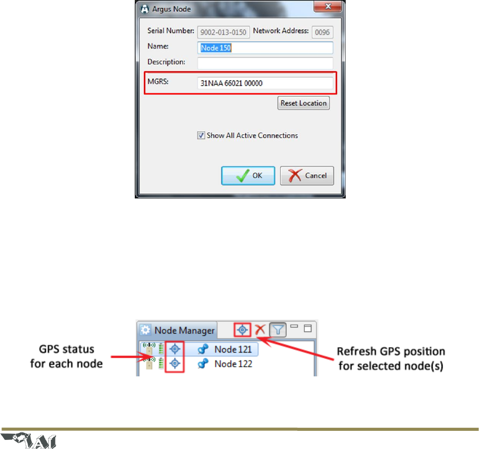
If an ARGUS GUARDIAN node has an enabled GPS module and is positioned outdoors, the GPS fix
information may be used to position the node on the map. The GPS status of each node is indicated in
the Node Manager panel by presence of a small satellite icon immediately to the left of the node name
(see Figure 16). If the icon is present, this indicates that a valid GPS fix has been obtained for the node.
Figure 16: Node Manager panel with GPS indicator icons highlighted
Page | 16
© 2018 Intelligent Automation, Inc.
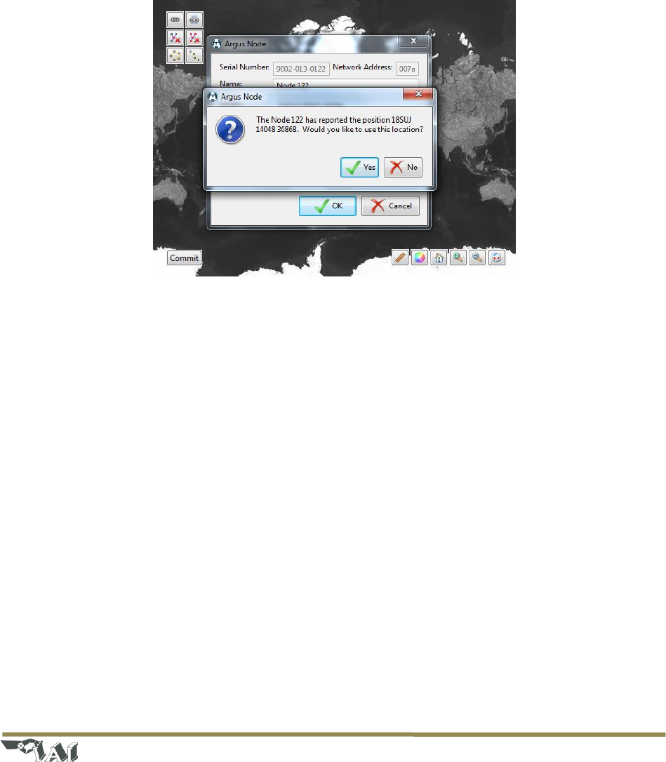
If a particular node does have a valid GPS fix, the on-screen location of the node can be updated
according to the latest fix provided by the GPS. To do so, first bring up the Node Configuration Window,
either by clicking the node in the Map View or by right clicking the node in the Node Manager panel and
selecting ‘Properties’. Then click the ‘Reset Location’ button. A prompt will be displayed to confirm that
the user wishes to update the node’s position to the latest GPS fix (see Figure 17). If no GPS fix is
available, an error message will be displayed to the user. Alternately, the GPS positions of one or more
nodes may be refreshed by selecting the desired nodes in the Node Manager panel and then clicking the
satellite icon near the top of the Node Manager panel (see Figure 16).
Figure 17: Node Configuration Window - 'Reset Location' result
4.6 Link Configuration
The process of Link Configuration involves specifying which links the user wishes to monitor. Since the
hardware may ‘see’ several viable links per node and cannot automatically determine which links may
be of interest to the user, the user must manually configure the active links. There are multiple methods
available for configure the links.
4.6.1 Link Configuration Window
For relatively simple deployments (a handful of nodes), the most straightforward method for configuring
links is to click on each link to make them active/inactive as desired. Within the Map View, simply click
on a link between two nodes to pop up the Link Configuration Window (see Figure 20). Within this
window, the link can be set to Active or Inactive by selecting the appropriate radio button. Also, this
window gives the option for the user to provide a textual link description (e.g., ‘North link’) that, if
provided, will be used in any alert indications.
Page | 17
© 2018 Intelligent Automation, Inc.
Figure 18: Link Configuration Window
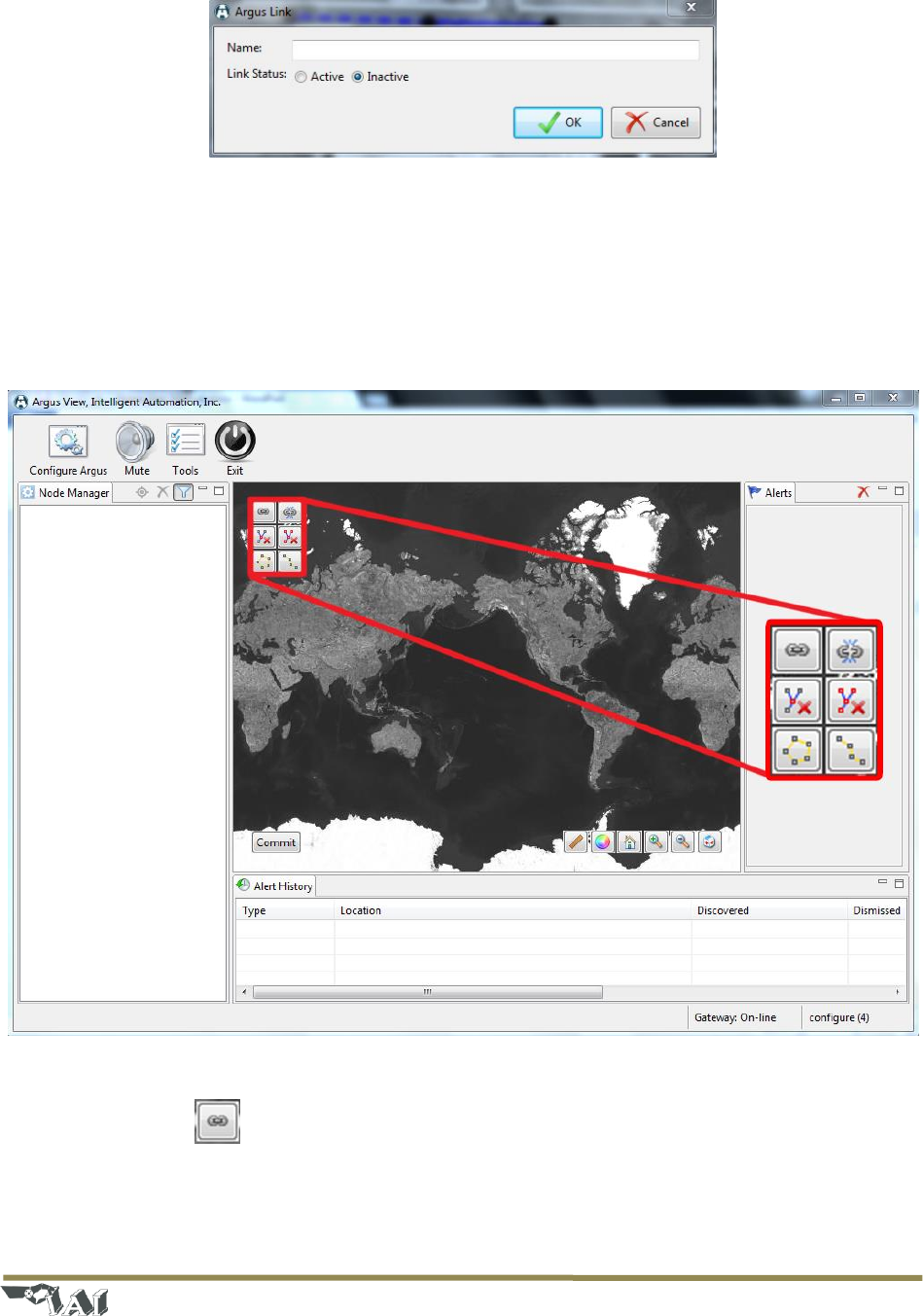
4.6.2 Link Configuration Toolbar
As an alternative to manually clicking on each individual link to enable/disable them, a Link
Configuration Toolbar is provided in the upper left corner of the Map View (see Figure 19). This toolbar
includes six buttons that enable rapid configuration of the Active/Inactive status of links, which is
particularly useful in larger ARGUS GUARDIAN deployments.
Figure 19: Link Configuration Toolbar (upper left corner of the Map View in Configuration Mode)
Link Mode 4.6.2.1
Link Mode enables the user to rapidly activate links by sequentially selecting the nodes within the Map
View. This mode is enabled by clicking the upper left icon in the Link Configuration Toolbar, and will
remain enabled until the icon is clicked again. When the Link Mode is enabled, any node clicked in the
Page | 18
© 2018 Intelligent Automation, Inc.
Map View will have the link to the next most recently clicked node made active (if a viable link exists
between the two nodes). This process can continue to enable any number of links.
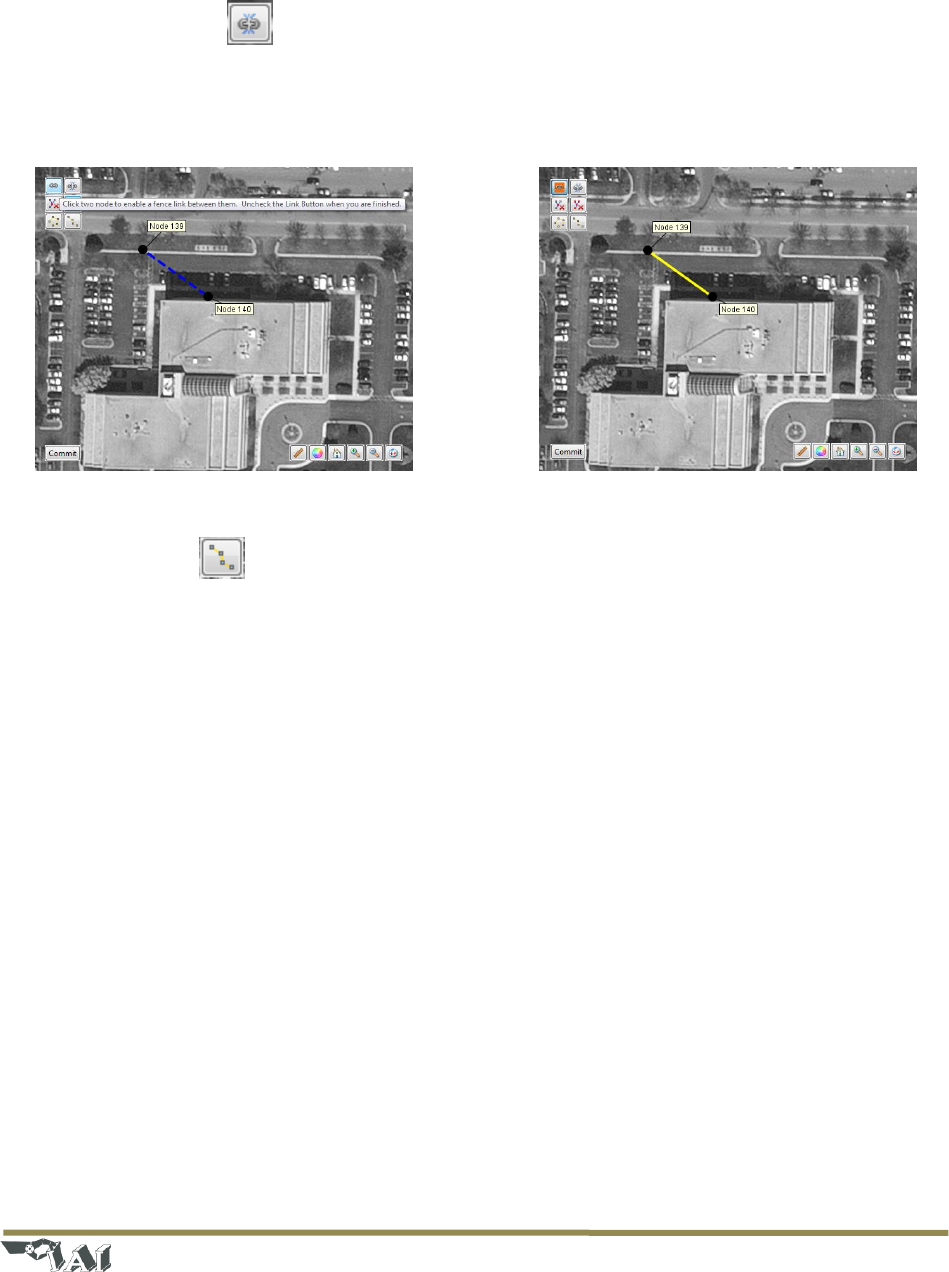
Unlink Mode 4.6.2.2
Unlink Mode is the opposite of Link Mode – any node clicked in the Map View will in the Map View will
have the link to the next most recently clicked node made inactive. This mode is enabled by clicking the
upper right icon in the Link Configuration Toolbar, and will remain enabled until the icon is clicked again.
Figure 20: A single fence link before (left) and after (right) enabling the link
Line Mode 4.6.2.3
Line Mode enables the user to rapidly activate an entire sequence of links that are in a roughly linear
configuration. This mode is enabled by clicking the lower right button in the Link Configuration Toolbar,
and remains active only until the set of nodes has been selected. After clicking the Line Mode icon, the
user can click and drag to box-select a set of nodes for which to configure as a line. Once the nodes have
been selected, the software will attempt to automatically configure the set of nodes in a roughly linear
topology. See Figure 21 for an example of the Line Mode tool in operation.
Note that this tool can be used to select all nodes in the configuration, or just a subset of the nodes.
Also, the tool will not modify links that are to/from nodes outside of the set of selected nodes. Thus, this
tool can be used to configure a part of the deployment that happens to be linear, and then use the other
methods to configure other links as desired.
Page | 19
© 2018 Intelligent Automation, Inc.
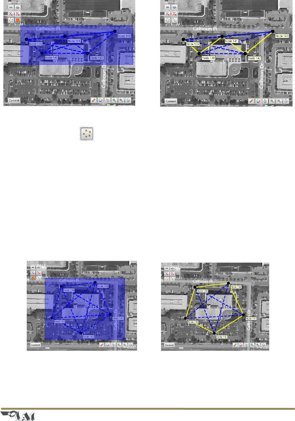
Figure 21: A set of links configured with Line Mode from the toolbar
Perimeter Mode 4.6.2.4
Perimeter Mode enables the user to rapidly activate an entire sequence of links that are in a roughly
circular configuration. This mode is enabled by clicking the lower left button in the Link Configuration
Toolbar, and remains active only until the set of nodes has been selected. After clicking the Perimeter
Mode icon, the user can click and drag to box-select a set of nodes for which to configure as a
perimeter. Once the nodes have been selected, the software will attempt to automatically configure the
set of nodes in a roughly circular topology. See Figure 22 for an example of the Perimeter Mode tool in
operation.
Note that this tool can be used to select all nodes in the configuration, or just a subset of the nodes.
Also, the tool will not modify links that are to/from nodes outside of the set of selected nodes. Thus, this
tool can be used to configure a part of the deployment that happens to be a perimeter, and then use the
other methods to configure other links as desired.
Figure 22: A set of links configured with Perimeter Mode from the toolbar
Page | 20
© 2018 Intelligent Automation, Inc.
Remove Node Links Mode 4.6.2.5
Remove Node Links Mode enables the user to rapidly deactivate all links connected to a particular node
simply by clicking on the node. This mode is enabled by clicking on the center right icon in the Link
Configuration Toolbar, and will remain enabled until the icon is clicked again.
Remove All Links 4.6.2.6
The Remove All Links button is the center left icon in the Link Configuration Toolbar. Clicking this button
will deactivate all links from all nodes in the configuration.
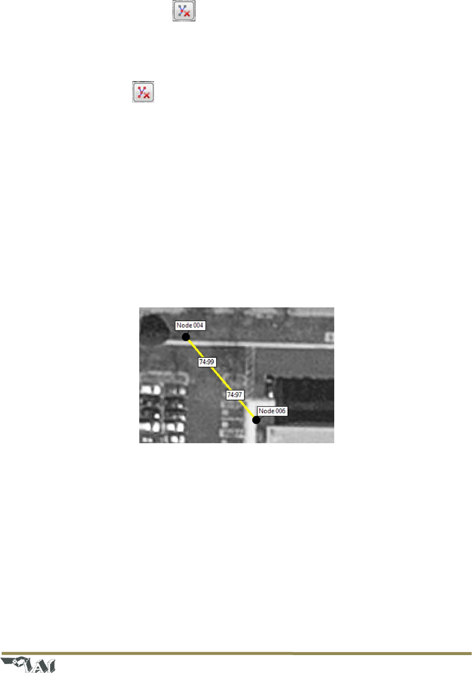
4.7 Link Metrics Mode
In either Configuration Mode or Active Mode, clicking the ‘Link Metrics’ button on the View Control
Toolbar (see Figure 12) activates the Link Metrics Mode. This mode enables the display of real-time link
metrics for each active link in the configuration (see Figure 23), including received signal strength
indicator (RSSI) and packet reception rate (PRR).The numbers are presented as a pair in the form
RSSI:PRR, and there are two pairs displayed for each link (one set of link measurements reported by
each node). The value for RSSI is bound in the range of 0-255, although values in the range of 30-100 are
generally seen. The value for PRR is bound in the range of 0-100.
Figure 23: Link Metrics Mode activated for fence link
4.7.1 Link Metrics Guidelines
The link metrics are useful as an indication of the ‘quality’ of a particular link. In general, links with
higher RSSI and PRR metrics perform better than links with lower metrics. The recommended minimum
RSSI metric for a quality link is 50, and the recommended minimum PRR is 90.
4.8 Alerts
Once in Active Mode, the ARGUS GUARDIAN software can present several types of alerts to the user.
- Perimeter Breach – This is the primary type of alert that the software will display, and indicates
that something or someone has passed through a link that is configured to be active. This alert
Page | 21
© 2018 Intelligent Automation, Inc.
will display in the Alerts panel on the right side of the GUI and will have a corresponding
graphical indication in the Map View – the link will flash red and then pulse orange until the
alert has been ‘handled’ or ‘dismissed’.
- Low Battery – This alert indicates that the node is reporting a low battery voltage, and the
batteries should be replaced or recharged soon.
- Node Failure – This alert indicates that the node has stopped reporting updates to the ARGUS
GUARDIAN control software for some period of time. This alert generally means that the node
has failed for some reason (dead battery, turned off or destroyed, disconnected antenna, etc.),
but could also be caused by a jammer preventing one or more nodes from transmitting. When
node failure occurs, links connected to that node turn purple.
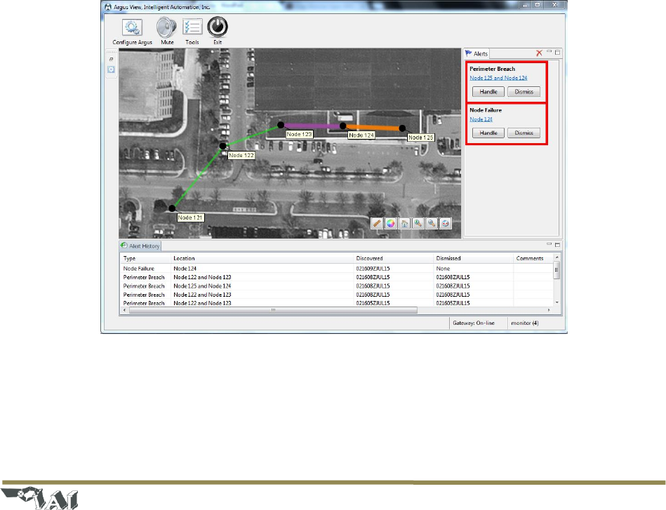
For all types of alert, an alert indication will be displayed in the Alerts panel on the right side of the GUI
(see Figure 24), and an alert entry will be added to the Alerts log at the bottom of the GUI. The user is
expected to ‘handle’ or ‘dismiss’ each alert in the Alerts panel. Pressing the ‘Handle’ button for the
particular alert will allow the user to enter some text to explain the cause and/or resolution of the alert
(e.g., ‘dog crossed’, ‘changed battery’, etc.). Pressing the ‘Dismiss’ button for an alert will allow the user
to clear the alert without entering any information. The red ‘X’ at the top of the Alerts panel will dismiss
all currently active alerts.
Figure 24: Screenshot showing a 'perimeter breach' alert and a ‘node failure’ alert
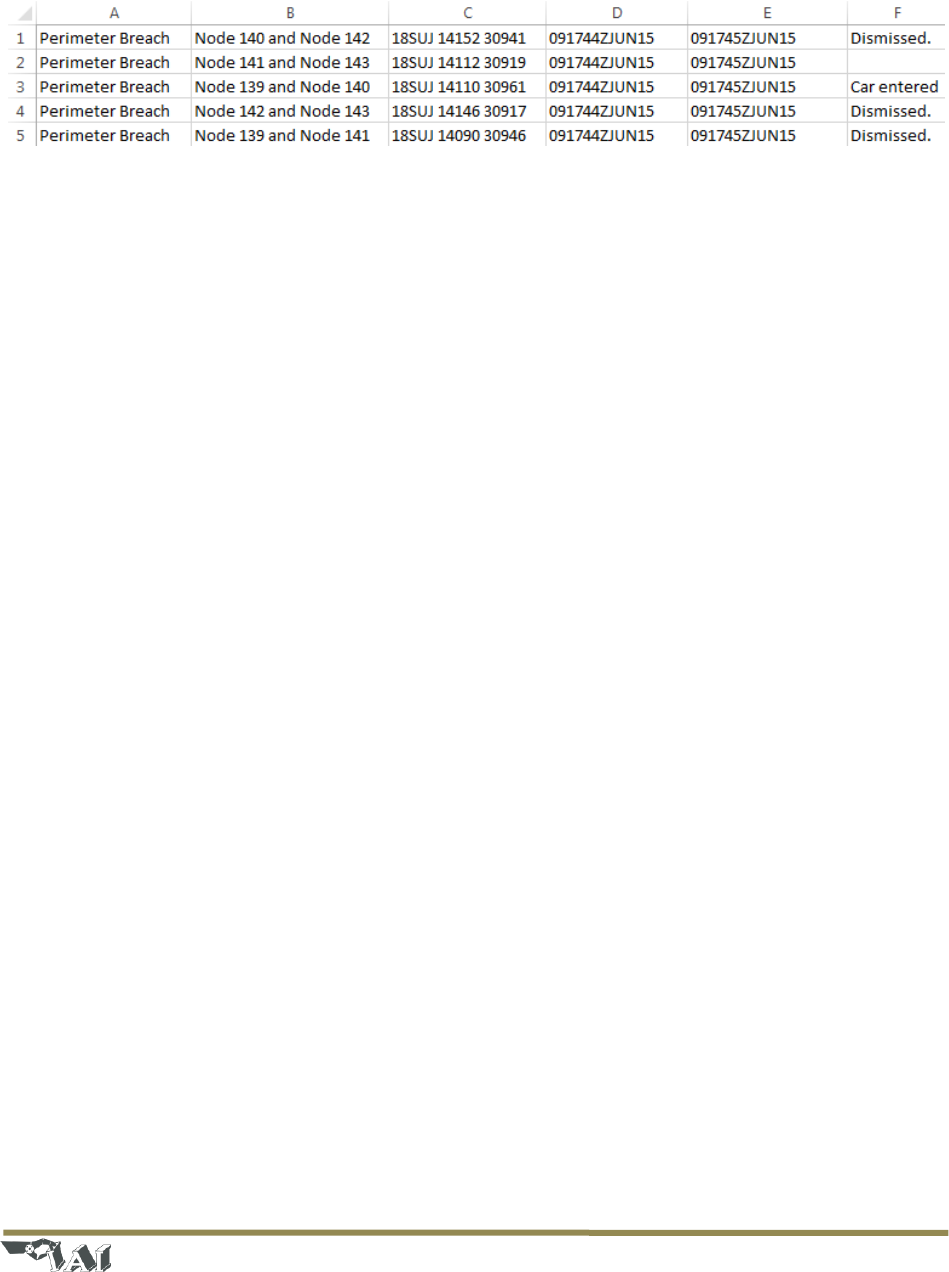
4.8.1 Alert Log Files
Alert logs are stored in the logs folder of the ARGUS GUARDIAN application directory, C:\ARGUS
GUARDIAN\logs, as a .csv file. Alert log filenames contain the date, time, and end with “alerts.” The
Page | 22
© 2018 Intelligent Automation, Inc.
file contains information about the alert type, nodes involved, location, discovery and dismissal time,
and comments.
Figure 25: Alert log file contents
4.9 Plug-in Configuration
Some versions of the RF Fence installation may have optional plug-ins installed, such as camera
monitoring or SMS/MMS notifications. If these are available, additional configuration windows will
appear during the Configuration Wizard and additional options may be available within the system.
4.9.1 Camera Plug-in
The Camera Plug-in allows ARGUS GUARDIAN operators to integrate existing camera systems within the
ARGUS GUARDIAN system. This is configurable with the Configuration Wizard and during Configuration
Mode.
1) Enable cameras for your deployment
a. Press the Configure tool bar button to launch the Configuration Wizard.
b. Navigate to the Camera Monitoring page in the wizard.
c. Set Camera Monitoring to Enabled.
d. (Optional) Scan the network for available cameras. Press the Scan button and all of the
available cameras will be displayed in the list below.
e. (Optional) Test the video stream from the Camera. Press the Show button to open a
stream to the camera. Streams may take up to 5 seconds to initialize.
Page | 23
© 2018 Intelligent Automation, Inc.
Figure 26: Camera Monitoring Configuration Window
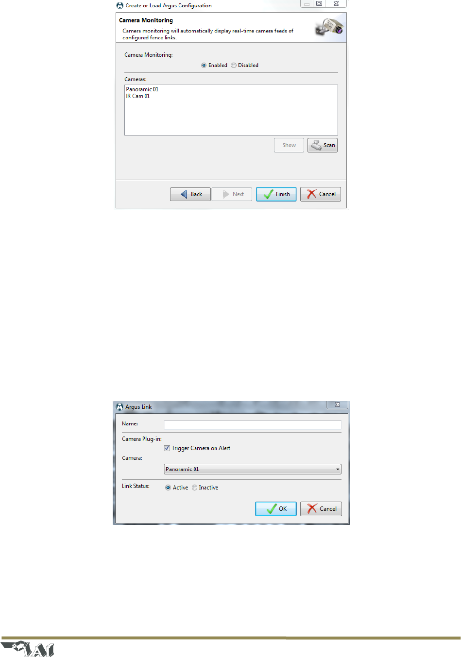
2) Configuring cameras for use in the ARGUS GUARDIAN system
a. Camera nodes will appear in the Node Manager view on the left. Camera nodes can be
positioned, just like ARGUS GUARDIAN nodes, by dragging from the Node Manager view
to their desired location on the Map Editor.
b. After the ARGUS GUARDIAN deployment has been configured, click a link in the Map
Editor that should be mapped to a particular camera. This will bring up the Link
Configuration dialog.
c. With the Link Configuration dialog, check the option Trigger Camera on Alert. By default
the option is displayed. When checked, the ARGUS GUARDIAN system will automatically
display the video feed from the selected camera.
Figure 27: Link Configuration Dialog with Camera Plug-in
4.9.2 Text Message Plug-in
The Text Message Plug-in allows ARGUS GUARDIAN operators to forward alerts to mobile phone via Text
or Multimedia Messages. This is fully configurable within the Configuration Wizard. Note that an active
Internet connection is required for this feature to operate.
Page | 24
© 2018 Intelligent Automation, Inc.
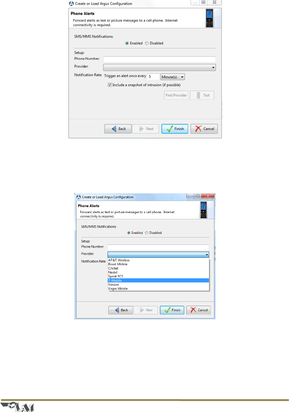
Figure 28: Phone Alerts Configuration Window
1) Navigate to the Phone Alerts page in the wizard.
2) Set SMS/MMS Notifications to Enabled.
3) Enter the phone number, area code first, of the recipient.
Figure 29: Phone Alerts Provider Selection
4) Select the cell phone provider. (This information is used to properly route the message). If you
are unsure of the provider of the cell phone you are using, press the Find Provider button and
the system will attempt detect it.
Page | 25
© 2018 Intelligent Automation, Inc.
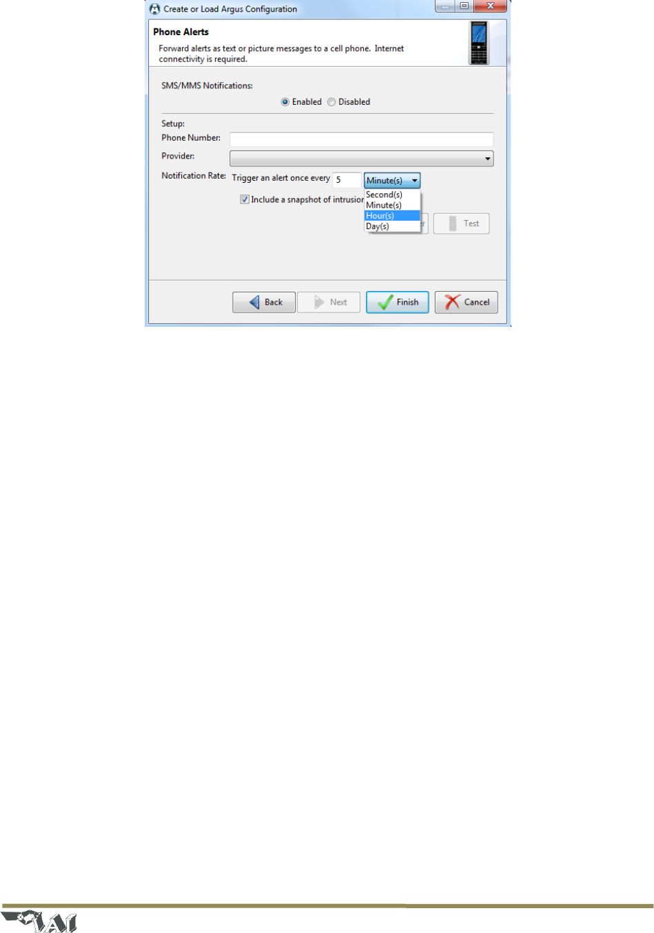
Figure 30: Phone Alerts Notification Rate Selection
5) Enter the notification rate. The default value is a maximum of one alert every 5 minutes.
6) (Optional) Check the Include a snapshot of the intruder (if possible) button to enable
Multimedia Messages. This option is only available to ARGUS GUARDIAN installations
supporting the Camera Plug-in.
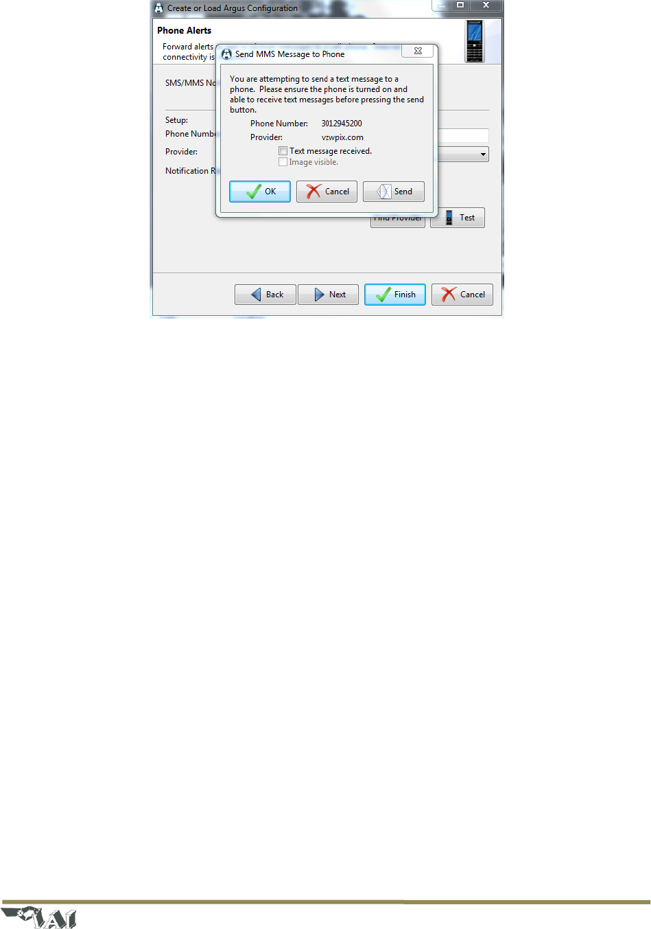
7) (Optional) Test that the ARGUS GUARDIAN system can send alerts to your phone.
a. Press the Test button.
b. Press the Send button, and wait for the alert to be received on your phone. This can
take up to 30 seconds.
c. (Optional) For Multimedia Messages, be sure that an image was present in the received
message.
Page | 26
© 2018 Intelligent Automation, Inc.
Figure 31: Phone Alerts Test Message
5 System Shutdown
Use the Exit button on the main toolbar (see Figure 10) to shut down the system. Once the user
interface is closed, turn off all nodes to complete the shutdown. To turn off each node, press and hold
the power button for at least 5 seconds. The node will flash the LED red three times and shut itself off.
Page | 27
© 2018 Intelligent Automation, Inc.
6 Node Deployment Guide
This section presents many tips and pointers regarding the physical deployment of the ARGUS
GUARDIAN nodes. As the system is based on RF propagation, it is sometimes difficult to always
determine if and how well a given link will work prior to deployment. The following guidelines will help
installers to effectively deploy the ARGUS GUARDIAN system. With a little experience, installers will
develop an intuitive sense of what deployment strategy will be effective in a given situation.
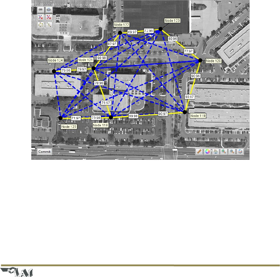
1) We recommend that you give a little thought to deployment strategy prior to beginning placing
nodes. Try to position each node so that it will have the best exposure to adjacent nodes in the
fence. When it makes sense for the deployment, try to also have single nodes monitor several
links simultaneously – there is no performance penalty for doing this. For example, see figure
38, which shows 2 nodes participating in three links each (the blue dotted lines represent all
possible links, whereas the yellow links represent the active links).
Figure 32: Example deployment with nodes 118 and 121 participating in 3 links each
2) The best link performance will be achieved when two nodes have line-of-sight (LOS) and are at a
maximum distance of 200 feet in fairly open areas, or 100 feet with nearby buildings. If
deploying the system indoors, the maximum node-to-node distance is reduced further, perhaps
down to 10 or 20 feet (this depends very much on the composition of the structure and nearby
reflective materials).
3) For detecting walking humans, the nodes should be mounted such that the antennas are vertical
and are located at about hip/waist height (~3-4 ft). If detecting crawling humans is required,
position the nodes slightly lower (~2-3 ft) and spaced no farther apart than 100 ft.

Page | 28
© 2018 Intelligent Automation, Inc.
4) The fence signal cannot penetrate tree trunks, light posts, cars, etc. If one of these obstacles is in
the direct path between two nodes, the link may still work, but the region of sensitivity will be
along a reflected path around the obstacle, rather than through the obstacle. Thin “RF
transparent” obstacles (many plastics, thin wood signs, light foliage, camouflage netting, fabric,
etc.) can usually be penetrated directly.
5) The installation terrain should also be taken into consideration when deploying the system. The
fence signals cannot penetrate the ground, nor will they go down into deep dips and gullies
between two nodes. Thus, the nodes should generally be placed in such a way that the terrain
between adjacent nodes is more or less even.
6) The system can be used with various antenna types. The connection on the top of the node is a
TNC female jack, so the mating connector (generally part of the antenna itself) must be a TNC
male plug. In general, longer antennas will have higher gain patterns, and may offer slightly
longer operating ranges. Note that the antenna must be rated to operate in both the 2.4GHz
and 900MHz bands.
7) In the event that a working node suddenly begins reporting low RSSI and/or PRR measurements
and possibly begins false triggering frequently, check to make sure that the installation method
has not failed (e.g., the tripod fell over).
8) In general, avoid placing links parallel to a nearby building or other strong reflector. Part of the
RF signal energy will travel along the reflected path, so you may inadvertently have a sensitive
region along that reflected path (although in some circumstances this may be acceptable or
even desired).
9) In general, avoid placing links parallel to a high traffic road. The RF signal energy will bounce off
of vehicles driving along the road and may sometimes trigger the fence (although in some
circumstances this may be acceptable or even desired).
10) Avoid placing links running in between two strong reflectors, such as running down a long
alleyway. The RF signal energy will travel along many reflected pathways simultaneously, such
that the link becomes completely insensitive to an intruder passing through. Running across
such an alleyway is fine, just not along the alleyway lengthwise.

Page | 29
© 2018 Intelligent Automation, Inc.
7 Troubleshooting
Problem: A link is generating too many false alarms (i.e., false positives)
Possible Solutions:
Do not position either end of a link close to human activity that should not trigger the fence.
Moving close to either node may trigger the link, even if not physically in between the two
nodes. Try adjusting the location of one or both of the nodes.
Make sure the link does not try to pass through any highly RF reflective/absorptive materials
(metal, cinder block, etc.). If so, move one or both ends of the link to avoid the obstruction.
Note that RF signals will bounce off of nearby hard surfaces (metal, sides of buildings, etc.), so
the region of sensitivity may be larger than simply the straight line between two nodes.
Similarly, nearby moving metallic objects (moving cars, opening doors, etc.) may trigger the link.
If this is not desired, try slightly repositioning one or both ends of the link.
Problem: A link is not triggering when it should (i.e., false negatives)
Possible Solutions:
Just as nearby reflective objects may cause false alarms (see above), it is also possible that these
objects could prevent some actual triggers by spreading the RF energy over too wide an area.
Try slightly repositioning one or both ends of the link.
Problem: The system is non-responsive (i.e., no triggers)
Possible Solutions:
Make sure all of the deployed ARGUS GUARDIAN nodes are powered on. If node is
unresponsive, its battery are probably discharged – replace with fully charged battery.
Make sure the Gateway node is plugged in. If you unplug and replug the gateway, it may take
several minutes for the nodes to rejoin the network.
If the USB cable was jostled during operation, the serial connection to the Gateway Node may
have been lost. Try shutting down the ARGUS GUARDIAN software, unplug and re-plug the USB
cable, and then restart the ARGUS GUARDIAN software.
Click on the link health button to view status of links. If link status labels displays 0 (zero), reset
all nodes and the user interface.

Page | 30
© 2018 Intelligent Automation, Inc.
Notes

Page | 31
© 2018 Intelligent Automation, Inc.

Page | 32
© 2018 Intelligent Automation, Inc.
FCC ID: 2AI6Y-GUARDIAN
This device complies with part 15 of the FCC Rules.
The Argus Guardian radiated output power is far below the FCC radio frequency exposure limits. Argus
The Argus Guardian complies with FCC radiation exposure limits set forth for an uncontrolled
environment. When nearby persons has to be kept to ensure RF exposure compliance, in order to
comply with RF exposure limits established in the ANSI C95.1 standards, the distance between the
antennas and the user should not be less than 20 cm (8 inches). The Argus Guardian shall not be co-
located with any other transmitter within 20 cm; otherwise further transmitter testing may be required.
Changes or modifications not expressly approved by the party responsible for compliance could void the
user’s authority to operate the equipment.
NOTE: This equipment has been tested and found to comply with the limits for a Class A digital device,
pursuant to part 15 of the FCC Rules. These limits are designed to pro-vide reasonable protection
against harmful interference when the equipment is operated in a commercial environment. This
equipment generates, uses, and can radiate radio frequency energy and, if not installed and used in
accordance with the instruction manual, may cause harmful interference to radio communications.
Operation of this equipment in a residential area is likely to cause harmful interference in which case the
user will be required to correct the interference at his own expense.
IC: 24338 - GUARDIAN
Operation is subject to the following two conditions: (1) this device may not cause interference, and (2)
this device must accept any interference, including interference that may cause undesired operation of
the device.
L’exploitation est autorisée aux deux conditions suivantes: (1) l’appareil ne doit pas produire de
brouillage, et (2) l’utilisateur de l’appareil doit accepter tout brouillage radioélectrique subi, même si le
brouillage est susceptible d’en compromettre le fonctionnement.

Page | 33
© 2018 Intelligent Automation, Inc.
For more information contact:
Intelligent Automation, Inc.
15400 Calhoun Drive, Suite 190
Rockville, MD 20855
301-294-5200
www.i-a-i.com