Intelyt orporated ICHIMEV20 Wireless radio module using 802.15.4 User Manual iCHIMEQuickStartManual Rev2
iControl Incorporated Wireless radio module using 802.15.4 iCHIMEQuickStartManual Rev2
Users Manual
iControlIncorporated
http://www.iControl‐Inc.com
iCHIMEModule
iTAGRepeaterfor
iCHIMEmodules
iCHIMEReaderutilizingan
InternaliCHIMEModule
iCHIMEModule
OperatingManual
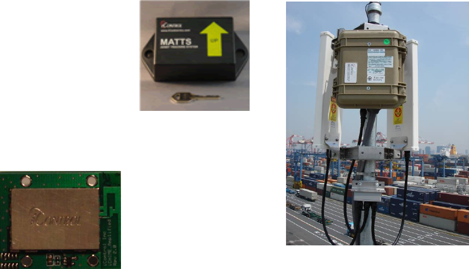
Background.
TheiCHIMEis2.4GHzbi‐directionalradiotransceiver.AUsermayconfigurethedevicetooperateasa
RadioFrequencyIdentificationDevice(RFID)tosupporttrackingshippingcontainersinaworldwide
supplychainusingtheMarineAssetTagTrackingSystem(MATTS)communicationprotocol.AniCHIME
moduleutilizesalowpower,wireless,radiooperatinginthe2.4GHzbandasitsprimarymodeof
communication.ThewirelessradiooperatesincompliancewithIEEEStandard802.15.4‐2006.The
iCHIMEutilizesthesameradio,processor,andUserinterfacesoftwareasiControl’siTAGmodule.The
iCHIMEalsosupportsthesamecommandlistasiControl’siTAGmodule.TheiCHIMEisUser
configurabletoperiodicallytransmittheiCHIME’sstatususingadatainterfaceavailableviatheUser
connector.Themodulemayoperateasstandalonedeviceormaybeusedasaradiotransceiverfor
devicesthatcommunicatedataasapartofalargersystem.
TheUserinterfaceforthemoduleisatwenty(20)pinconnectoronthebottomofthemodule.
Figure1iCHIMEandRelatedDevices
iControlIncorporated
http://www.iControl‐Inc.com
iCHIMERadioOperation.
TheiCHIMEiscontrolledviaaserialportinterface(RS232UART)forinitialconfigurationandcheckout.
AllcommandsforcontrollingtheiCHIMEradioareidentifiedintheiTAGCommandList.OnceaUseras
completedtheinitialiCHIMEconfiguration,completecontrolandoperationoftheiCHIMEcanbe
accomplishedthroughtheradiointerfaceusingthesamecommandsavailableintheiTAGCommand
List.
TheradiointheiCHIMEisnormallyoperatedinapowersavingmodewiththereceiverperiodically
enabledand“listening”forcommandsordatarequests.Akeyelementtothepowersavingmodeis
theprincipleof“tag‐talks‐last”.Inthismode,batterypowerisconservedbyonlyrespondingto
messagesthataresentdirectlytothespecificiCHIMEMACaddressormutualbroadcastaddress.Fora
majorityofiCHIMEoperation,theiCHIMEisinadeeppowersavingmode(~98%ofthetime).The
iCHIMEwillonlytransmitwhenitreceivesaproperlyencryptedmessagewhileitsreceiverisactive.
TheencryptedmessagedirectedtotheiCHIMEmayincludeinformationaboutwhichchannelthe
iCHIMEusesforfurthertransmissions.Once,thecommunicationparametersareexchanged,therewill
typicallybeaperiodaseveralsecondsofactiveradiotransmissionastheiCHIMErelaysdata.Thedata
transmittedmayeitherbesecuritydatadestinedforgovernmentservers,and/orcommercialdata
destinedfortheendcustomer.Thisdatamayoriginatefrominternalflashstorageoritmaybereceived
andrelayedfromanothercompatibledevice.
OtherFeatures.
Inadditiontothewirelessradio,theiCHIMEprovidesotherfeaturesforsystemintegration.
1. TwoRS‐232serialUARTsareavailablefortheUsertocommunicatetothemodulefrom
secondarysystemstotransmitdataviatheradiotransceiver.TheUserhascompletecontrolfor
settingthebaudrate,dataintervalandpacketformatfordatatransmission.
2. TheiCHIMEhostseightchannelsof13bitresolutionAnalogtoDigitalconversion.Theseinputs
canbeusedtomonitorexternalsensorsattachedtotheiCHIME(temperature,pressure,
vibration,etc.).TheiCHIMEuserinterfaceincludescommandanddatahandlingsupportto
issuealarmsorautomatebehaviorbasedonthresholdsfortheseinput.
3. ThereisanonboardtemperaturesensorintegratedwithiCHIME.ThedefaultiCHIMEdata
packetincludesthetemperaturedata.
iControlIncorporated
http://www.iControl‐Inc.com
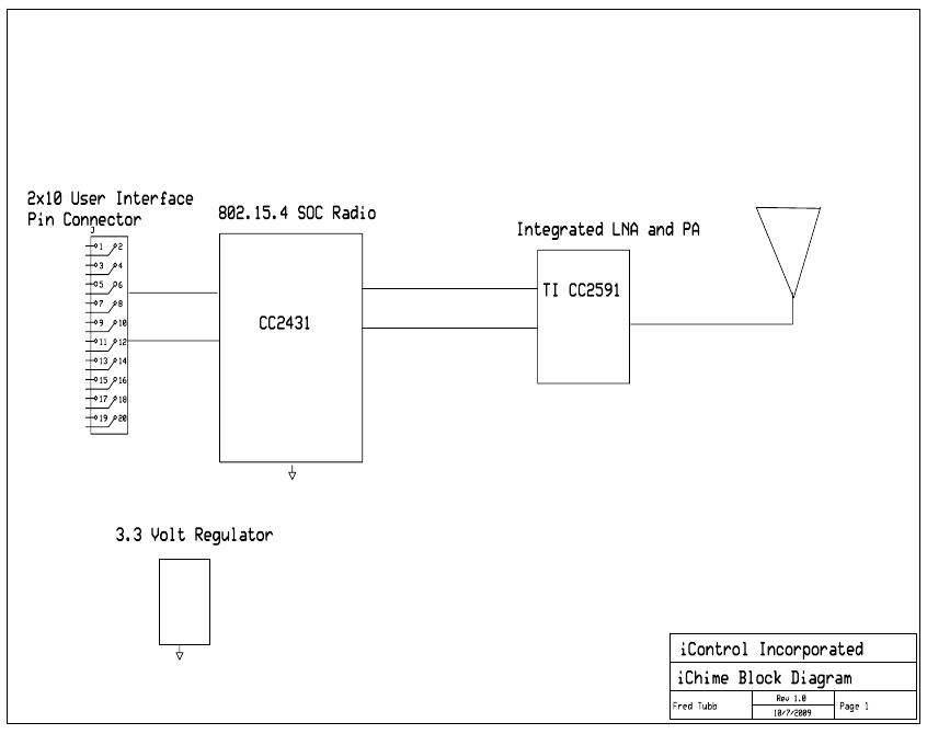
FunctionalBlockDiagram.
TheiCHIMEmoduleintegratesalowpowermicroprocessoranda2.4Ghzradio.TheiCHIMEmodule
alsoincludesasoftwareUserinterfaceforradiocontrolanddatatransmission.Additionally,the
iCHIMEcanretrieveUserdataviathetwoserialUARTsorprovideupto8channelsofanalogtodigital
data.
Note:PleasenotethattheiCHIMEusesthesamecommandlistastheiTAGcommandlist.ForiCHIME
commandandcontrol,pleaserefertotheiTAGCommandListforacompletedescriptionofcommands
thatcontroltheiCHIMEmodule.
TheiCHIMEmoduleisequippedwithanintegratedtraceantennaratedat3.0dBi.Mostembedded
mobileapplicationswillutilizetheintegralantennaprovidedwiththeiCHIMEmodule.
Optionally,amicrocoaxconnectormaybeutilizedtoconnectexternalantennatotheiCHIMEmodule.
iControlcanprovideiCHIMEmoduleswithexternalantennaconnectorsthatarecertifiedandlicensed
forexternalantennaoperations.
NOTE:Usersmaynotmodifytheantennaorit’sconnectioninanywayorriskviolatingradiolaw.
Figure2iCHIMEBlockDiagram
iControlIncorporated
http://www.iControl‐Inc.com
AbsoluteMaximumRatings.
Undernocircumstancesmusttheabsolutemaximumratingsgivinginthistablebeviolated.Stress
exceedingoneormoreofthelimitingvaluesmaycausepermanentdamagetothedevice.
Parameter Min Max Units Condition
Supply Voltage -0.3 6.0 V All supply pins must have same voltage
Voltage on any digital pin -0.3 3.6 V
Input RF level 10 dBm
Storage temperature range -50 150 C
Operating ambient temperature -40 85 C
Figure3MaximumRatings
iControlIncorporated
http://www.iControl‐Inc.com
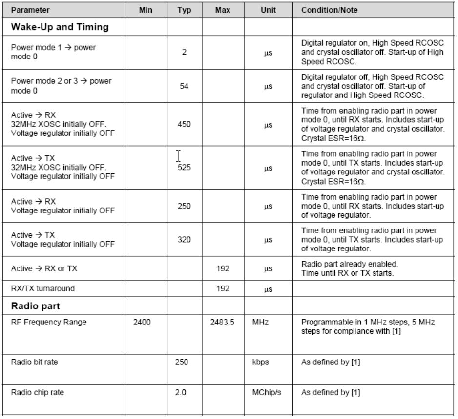
GeneralCharacteristics.
iControlIncorporated
http://www.iControl‐Inc.com
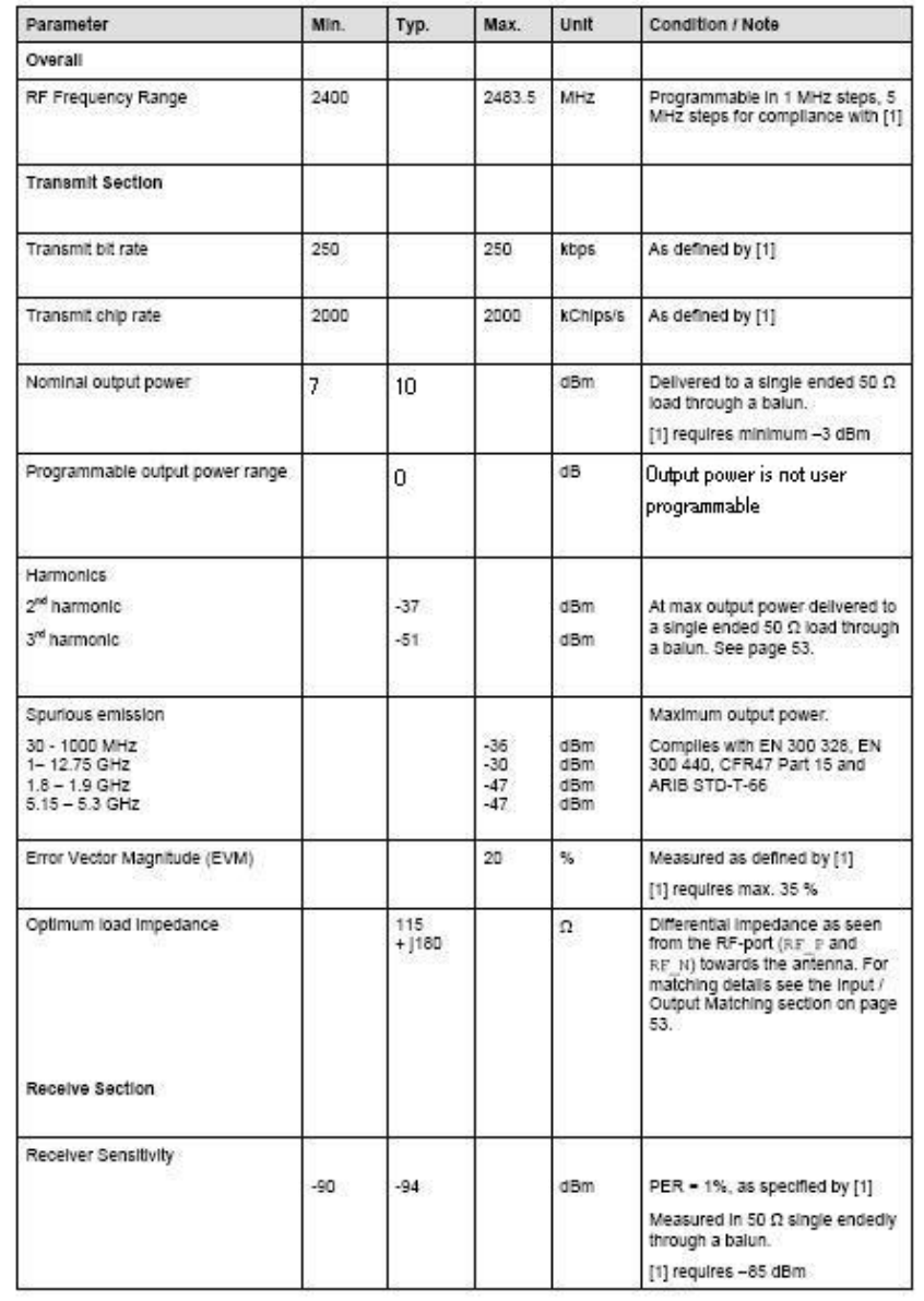
iCHIMERadioSpecification(Transmit).
iControlIncorporated
http://www.iControl‐Inc.com
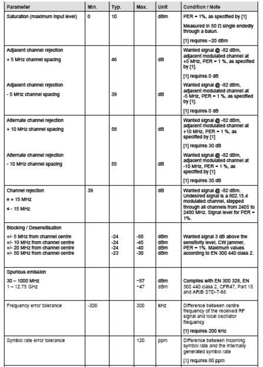
iCHIMERadioSpecification(Receive).

iControlIncorporated
http://www.iControl‐Inc.com
OEMInstallationInstruction:
AnOEMintegratorutilizesthe2x10x2mmpinheaderconnectoronthebottomoftheiCHIME.To
applypower,utilizeserialdata,andconnecttoanaloginterfaces,theOEMmustprovidea2x10x
2mmpinsocketontheirintegratingelectronics.
InterfaceSpecification.
TheinterfacediagramnotedbelowisforthematingconnectorontheUser’selectronics.Allinterfaces
totheradioarebufferedtopreventUserinterfaceelectronicsfrominterferingwiththeoperationofthe
radio.
PIN Name Type Description
1 GND PWR Ground
2 Analog 7 I Analog Channel 7 (0-3.3 V input)
3 Analog 4 I Analog Channel 4 (0-3.3 V input)
4 Analog 6 I Analog Channel 6 (0-3.3 V input)
5 Analog 5 I Analog Channel 5 (0-3.3 V input)
6 VIN PWR 3.3-6.0 V input
7 TXDB Output Serial Port B transmit output (0-3.3V)
8 RXDB Input Serial Port B receive input (0-3.3V)
9 TXDA Output Serial Port A transmit output (0-3.3V)
10 RXDA Input Serial Port A receive input (0-3.3V)
11 P1_1 I/O General Purpose I/O (0-3.3 V input)
12 P1_0 I/O General Purpose I/O (0-3.3 V input)
13 P2_0 I/O General Purpose I/O (0-3.3 V input)
14 PBReset Input Reset Pin, Active low, if not used keep float
15 P2_2 I/O General Purpose I/O (0-3.3 V input)
16 P2_1 I/O General Purpose I/O (0-3.3 V input)
17 Analog 3 I Analog Channel 3 (0-3.3 V input)
18 Analog 0 I Analog Channel 0 (0-3.3 V input)
19 Analog 2 I Analog Channel 2 (0-3.3 V input)
20 Analog 1 I Analog Channel 2 (0-3.3 V input)
(TopView)UsersMatingConnectorfor
iCHIMEModule

iControlIncorporated
http://www.iControl‐Inc.com
ModuleMechanicalSpecification.
TheiCHIMEmoduleismanufacturedona0.062”thickFR4PCBsubstrate.Therearefour0.10”
mountingholeswhichmaybeusedtosecurethemoduleinanenclosureortomountonahost
motherboard.Allradiocomponentsareintegratedunderamechanicallysecure,tamperproofRF
shield.
iCHIMEModuleMechanicalDimensions(ininches)

iControlIncorporated
http://www.iControl‐Inc.com
ModuleUniqueAddressIdentification.
EachiCHIMEmoduleisassignedaunique8byteMACaddressbyiControlIncorporated.TheMAC
addressisusedforradionetworkaddressidentification.TheMACaddresscannotbemodifiedbythe
Userandislocatedinprotectedflashmemory.Figure5depictsthecommunicationprotocolbetween
iControliCHIMEandtheiGATEreader.Thecommunicationprotocolutilizesaunique8byteMAC
addressdefinedbytheIEEE802.15.4standard.
InFigure5,
TheiCHIMEaddressis(0x0035A923000000002).
TheiGATEaddressis(0x0035A9230A010203)
Figure10
iControlIncorporated
http://www.iControl‐Inc.com
FCCCompliance:
This equipment has been tested and found to comply with the limits for a Class B digital device, pursuant
to Part 15 of the FCC rules. These limits are designed to provide reasonable protection against harmful
interference in a residential installation. This equipment generates, uses and can radiate radio frequency
energy and, if not installed and used in accordance with the instructions, may cause harmful interference
to radio communications. However, there is no guarantee that interference will not occur in a particular
installation.
Troubleshooting:
If this equipment does cause harmful interference to radio or television reception, which can be
determined by turning the equipment off and on, the user is encouraged to try to correct the interference
by one or more of the following measures:
1. Reorient or relocate the receiving antenna.
2. Increase the separation between the equipment and receiver.
3. Connect the equipment to an outlet on a circuit different from that to which the receiver is connected.
4. Consult the dealer or an experienced radio/TV technician.
Conditions:
Operation is subject to the following two conditions:
1. This device may not cause harmful interference
2. This device must accept any interference received, including interference that may cause undesired
operation.
Markings:
TosatisfyFCCexteriorlabelingrequirementsthefollowingtextmustbeplacedontheexteriorofthe
product.
ContainsModuleFCCID:FCCID:W2E‐ICHIMEV20
iControlIncorporated
http://www.iControl‐Inc.com
FCCWarnings:
Modifications: Modifications not expressly approved by the manufacturer could void the user’s
authority to operate the equipment under FCC Rules.
RadioFrequencyExposure:
Notes:
1)Formobileorfixedlocationtransmitterstheminimumseparationdistanceis20cm,evenifcalculators
indicatetheMPEdistanceisless.
2)ThisequipmenthasbeenevaluatedinaccordancewiththeFCCbulletin56“Hazardsofradio
frequencyandelectromagneticfields”andbulletin65“Humanexposuretoradiofrequencyand
electromagneticfields.
3)Safeoperationinanuncontrolledenvironmentwillresultifthefollowingdistancesfromthedevice
aremaintainedasaminimum.