InterLogix 1072575 R00.05 Ns2503 24P 2C Quick Installation Guide IFS 24P/2C User Manual
2015-08-27
User Manual: InterLogix 1072575 R00.05 Ns2503-24P 2C Quick Installation Guide
Open the PDF directly: View PDF ![]() .
.
Page Count: 11

P/N 1072575 • REV 00.05 • ISS 30JAN13
IFS NS2503-24P/2C
Quick Installation Guide
Copyright © 2013 UTC Fire & Security Americas Corporation, Inc.
Interlogix is part of UTC Climate Controls & Security, a unit of United
Technologies Corporation. All rights reserved.
Trademarks and patents The IFS NS2503-24P/2C Quick Installation Guide and logo are
trademarks of United Technologies.
Other trade names used in this document may be trademarks or
registered trademarks of the manufacturers or vendors of the respective
products.
Intended use Use this product only for the purpose it was designed for; refer to the
data sheet and user documentation for details. For the latest product
information, contact your local supplier or visit us online at
www.interlogix.com.
Manufacturer UTC Fire & Security Americas Corporation, Inc.
2955 Red Hill Avenue
Costa Mesa, CA 92626-5923, USA
EU authorized manufacturing representative:
UTC Fire & Security B.V., Kelvinstraat 7,
6003 DH Weert, The Netherlands
Certification N4131
FCC compliance This equipment has been tested and found to comply with the limits for a
Class A digital device, pursuant to part 15 of the FCC Rules. These limits
are designed to provide reasonable protection against harmful
interference when the equipment is operated in a commercial
environment. This equipment generates, uses, and can radiate radio
frequency energy and, if not installed and used in accordance with the
instruction manual, may cause harmful interference to radio
communications.
You are cautioned that any changes or modifications not expressly
approved by the party responsible for compliance could void the user's
authority to operate the equipment.
ACMA compliance Notice! This is a Class A product. In a domestic environment this
product may cause radio interference in which case the user may be
required to take adequate measures.
Canada This Class A digital apparatus complies with Canadian ICES-003.
Cet appareil numérique de la classe A est conforme á la norme
NMB-003du Canada.
European Union directives 2004/108/EC (EMC Directive): Hereby, UTC Fire & Security Americas
Corporation, Inc. declares that this device is in compliance with the
essential requirements and other relevant provisions of Directive
2004/108/EC.
2002/96/EC (WEEE directive): Products marked with this symbol
cannot be disposed of as unsorted municipal waste in the European
Union. For proper recycling, return this product to your local supplier
upon the purchase of equivalent new equipment, or dispose of it at
designated collection points. For more information see:
www.recyclethis.info.
Contact information For contact information see our Web site: www.interlogix.com.
Contact support www.interlogix.com/customer support
IFS NS2503-24P/2C Quick Guide
3
TABLE OF CONTENTS
IFS NS2503-24P/2C QUICK INSTALLATION GUIDE...................................................1
INTRODUCTION ..............................................................................................................4
Package Contents......................................................................................................................................4
Requirements .............................................................................................................................................4
Terminal Setup ...........................................................................................................................................4
Login in the Console Interface..................................................................................................................6
Configure IP address.................................................................................................................................6
Start Web-based Management..................................................................................................................8
Logging on the Managed Switch .......................................................................................................... 9
Resetting the IP address and Admin Password .................................................................................. 10
CONTACTING TECHNICAL SUPPORT ........................................................................11

IFS NS2503-24P/2C Quick Guide
4
Introduction
The IFS Layer 2 Managed Switch NS2503-24P/2C has 24 10/100Mbps 802.3at compliant PoE ports, with two Gigabit TP/SFP
fiber optical combo ports and robust layer 2 features. The NS2503-24P/2C also provides IEEE 802.3af / IEEE 802.3at Power
over Ethernet standards to meet requirements for various PoE applications.
Package Contents
Open the box of the Managed Switch and carefully unpack it. The box should contain the following items:
Check the contents of your package for following parts:
The Managed Switch x1
Quick Installation Guide
User’s Manual CD x1
x1
19” Rack mount Accessory Kit x1
Power Cord x1
Rubber Feet X4
RS-232 DB9 Male Console Cable x1
If any of these are missing or damaged, please contact your distributor or IFS sales rep immediately, if possible, retain the
original carton and packaging material in case you need to return the product for repair/replacement.
Requirements
The operating system of the workstation running Windows XP/2003, Vista, Windows 7, MAC OS X , Linux, Fedora,
Ubuntu or other platform compatible with TCP/IP protocols.
Workstation installed with Ethernet NIC (Network Interface Card)
Ethernet Port connection
Network cables - Use standard network (UTP) cables with RJ45 connectors.
Above Workstation installed with WEB Browser and JAVA runtime environment Plug-in
Serial Port connection
Above PC with COM Port (DB-9 / RS-232) or USB-to-RS-232 converter
It is recommended to use Internet Explore 6.0 or above to access Managed Switch.
Terminal Setup
To configure the system via terminal connection, connect a serial cable to a COM port on a PC or notebook computer and to
serial (console) port of the Managed Switch. The console port of the Managed Switch is DCE already, so that you can connect
the console port directly through PC without the need of Null Modem.
IFS NS2503-24P/2C Quick Guide
5
Figure 1: Console Management Diagram
A terminal program is required to make the software connection to the Managed Switch. Windows' Hyper Terminal program
may be a good choice. The Hyper Terminal can be accessed from the Start menu.
1. Click START, then Programs, Accessories and then Hyper Terminal.
2. When the following screen appears, make sure that the COM port should be configured as:
57600 bps
8 data bits
No parity
1 stop bit
Figure 2: Terminal Parameter Settings
You can change these settings, if desired, after you log on. This management method is often preferred because you can
remain connected and monitor the system during system reboots. Also, certain error messages are sent to the serial port,
regardless of the interface through which the associated action was initiated. A Macintosh or PC attachment can use any
terminal-emulation program for connecting to the terminal serial port. A workstation attachment under UNIX can use an
emulator such as TIP.
IFS NS2503-24P/2C Quick Guide
6
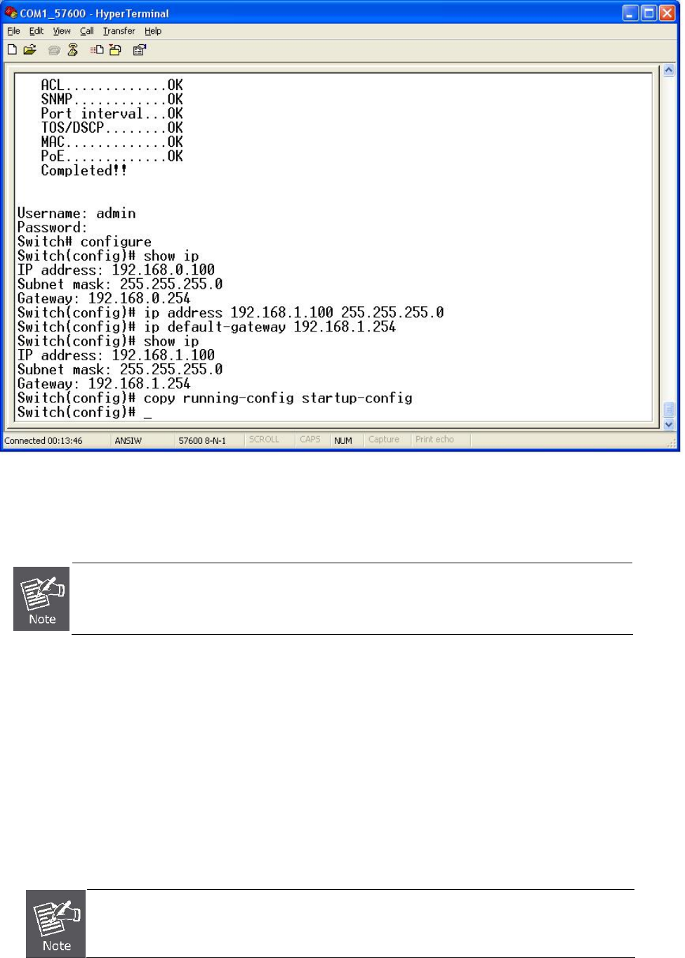
Login in the Console Interface
Once the terminal has connected to the device, turn on the Managed Switch, and the terminal will display the status of testing
being performed.
Then, the following message asks the login user name and password. The factory default user name / password as following
and the login screen in Figure 3 appears.
Username: admin
Password: admin
Figure 3: Managed Switch Console Login Screenshot
1. For security reasons, please change and memorize the new username and password after
this first setup.
Username Max: 6, Min: 1 characters.
Password Max: 6, Min: 1 characters.
2. Only accept command in lowercase letter under console interface.
Configure IP address
The Managed Switch is shipped with the following default IP address.
IP Address : 192.168.0.100
Subnet Mask : 255.255.255.0
To check the current IP address or modify a new IP address for the Switch, please use the following procedures:
Show the current IP address
1. On ”Switch# ” prompt, enter “configure”.
2. On ”Switch(config)# ” prompt, enter “show ip”.
IFS NS2503-24P/2C Quick Guide
7
3. The screen displays the current IP address, Subnet Mask and Gateway. As show in Figure 4.
Figure 4: Show IP information Screenshot
Configure IP address
1. On “Switch(config)# ” prompt, enter the following command and press <Enter>. As show in Figure 5.
Switch(config)# ip address 192.168.1.100 255.255.255.0
Switch(config)# ip default-gateway 192.168.1.254
The previous command would apply the follow settings for the Switch.
IP: 192.168.1.100
Subnet Mask: 255.255.255.0
Gateway: 192.168.1.254
IFS NS2503-24P/2C Quick Guide
8
Figure 5: Set IP address Screenshot
2. Repeat Step 1 to check if the IP address is changed.
If the IP is successfully configured, the Managed Switch will apply the new IP address settings immediately. You can access the
Web interface of this Managed Switch through the new IP address.
If you are not familiar with console command or the related parameter, enter “help” anytime in
console to get the help description.
You can change these settings, if desired, after you log on. This management method is often preferred because you can
remain connected and monitor the system during system reboots. Also, certain error messages are sent to the serial port,
regardless of the interface through which the associated action was initiated. A Macintosh or PC attachment can use any
terminal-emulation program for connecting to the terminal serial port. A workstation attachment under UNIX can use an
emulator such as TIP.
Start Web-based Management
The Managed Switch offers management features that allow users to manage the Managed Switch from anywhere on the
network through a standard browser such as Microsoft Internet Explorer.
The Web-Based Management supports Internet Explorer 6.0. It is based on Java Applets with an aim to reduce network
bandwidth consumption, enhance access speed and present an easy viewing screen.
By default, IE6.0 or later version does not allow Java Applets to open sockets. The user has to
explicitly modify the browser setting to enable Java Applets to use network ports.
IFS NS2503-24P/2C Quick Guide
9
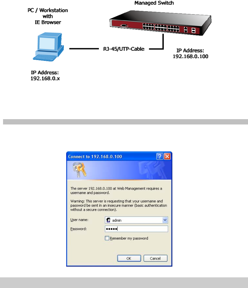
The Managed Switch can be configured through an Ethernet connection, make sure the manager PC must be set on same the
IP subnet address with the Managed Switch.
For example, the default IP address of the Managed Switch is 192.168.0.100, then the manager PC should be set at
192.168.0.x (where x is a number between 1 and 254, except 100), and the default subnet mask is 255.255.255.0.
If you have changed the default IP address of the Managed Switch to 192.168.1.1 with subnet mask 255.255.255.0 via console,
then the manager PC should be set at 192.168.1.x (where x is a number between 2 and 254) to do the relative configuration on
manager PC.
Logging on the Managed Switch
1. Use Internet Explorer 6.0 or above Web browser. Enter the factory-default IP address to access the Web interface. The
factory-default IP Address as following:
http://192.168.0.100
2. When the following login screen appears, please enter the default username “admin” with password “admin” (or the
username/password you have changed via console) to login the main screen of Managed Switch. The login screen in
Figure 6 appears.
Figure 6: Login Screen
Default User name: admin
Default Password: admin
3. After entering the username and password, the main screen appears as Figure 7.
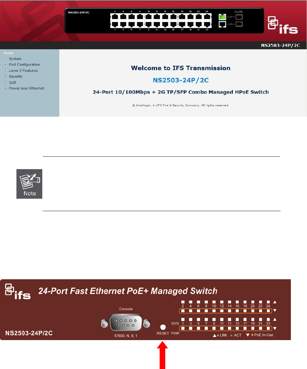
IFS NS2503-24P/2C Quick Guide
10
Figure 7: Web Main Page Screenshot
4. The Switch Menu on the left of the Web page let you access all the commands and statistics the Switch provides.
1. We recommend using Internet Explore 6.0 or above to access Managed Switch.
2. If the IP address of the switch is changed, the change will take effect immediately after you
have clicked on the Apply button, therefore you need to use the new IP address to access
the Web interface.
3. For security reasons, please change and memorize the new password after the first setup.
4. The Switch accepts commands in lowercase letters on the web interface.
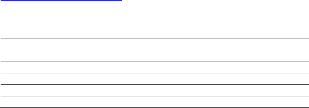
Resetting the IP address and Admin Password
To reset the IP address to the default IP Address “192.168.0.100” or reset the password to default value press the hardware
reset button at the front panel about 10 seconds. After the device is rebooted, you can login the management WEB interface
within the same subnet of 192.168.0.xx.
Reset
IFS NS2503-24P/2C Quick Guide
11
Contacting Technical Support
Contact technical support if you encounter any difficulties during this installation. Please make
sure you have the requested diagnostic or log files ready before you contact us by phone or go to
www.interlogix.com/customer-support.
Technical Support
Europe, Middle East and Africa
W Select Contact Us at www.utcfssecurityproducts.eu
North America
T +1 855.286.8889
E techsupport@interlogix.com
Australia
E techsupport@interlogix.au
