21 3602Erev1.5 XL Adv Instn24.05.12 X L
2015-08-27
: InterLogix 21-3602Erev1.5 Xl Adv Instn24.05.12 21-3602Erev1.5 xL Adv Instn24.05.12 library
Open the PDF directly: View PDF ![]() .
.
Page Count: 76

Advanced Installation Guide rev1.5
Also Supports
Upgrades
™

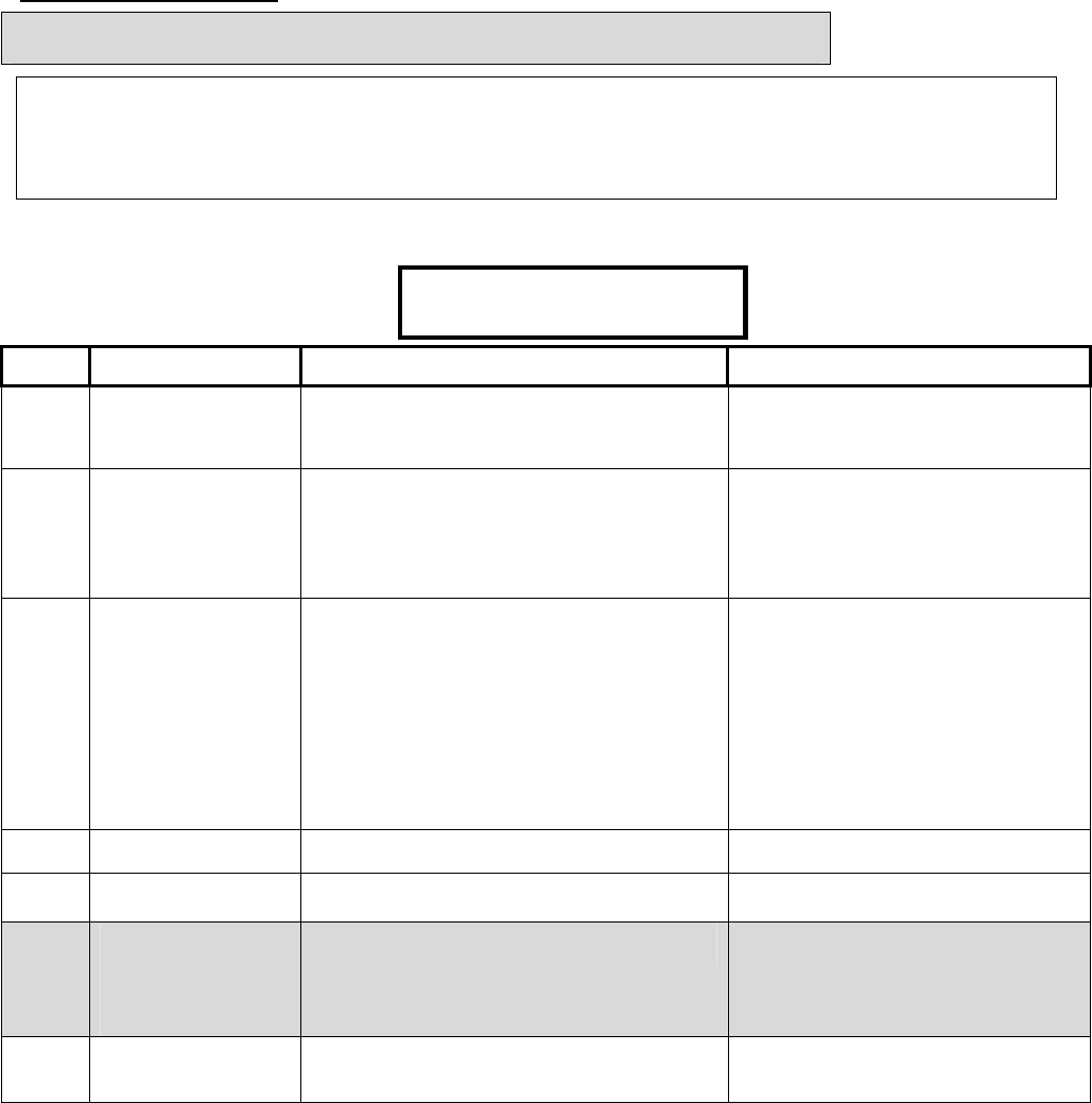
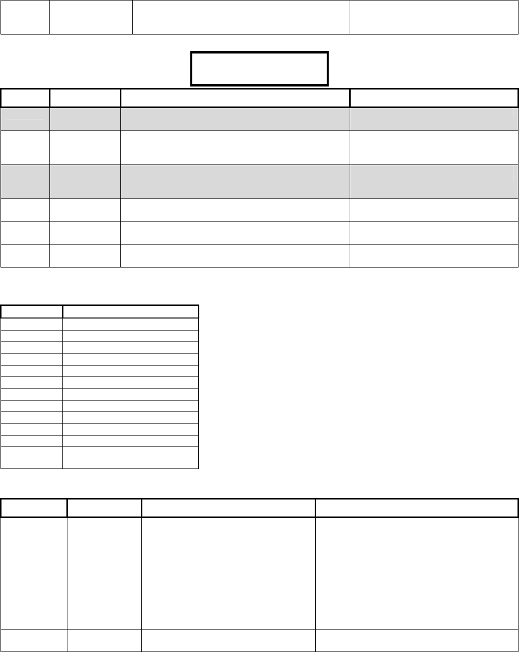
Monitor xL Feature Enhancements

Features Monitor ISM v4.3 Monito
r
xL v4.4
A
reas 16 16
Area Groups No Yes
Area Arm/Disarm Priority No Yes
Common Area Arm/Disarm No Yes
Input points (on board - expansion) 8 - 128 12 - 256
Output points (on board - expansion) 4 - 128 2 – 128
Users 20 – 64000 20 – 64000
Doors 32 32 (Feature Expansion board)
Readers per door 2 2
Floors (per account) 124 124
Modules 24 24
LCD Keypad Yes Yes
LCD Keypad with Gprox II No Yes
LCD Keypad with Wiegand Interface No Yes
Keypad inputs 1 4
8 Point Expansion Yes Yes
16 Point Expansion Yes Yes
319.5Khz Wireless Yes Yes
868/900 Mhz Wireless Yes Yes
Map Module Yes Yes
Door Controller Yes Yes
Fire Module Yes Yes
Elevator Controller Yes Yes
8 zone suite Yes Yes
2 zone suite Yes Yes
Authority levels 30 -1000 30-1000
Profiles 4 50-1000
Schedules 50 50-250
Floor Schedules (Elevator control) 3 common 124 individual + previous 3
Holidays 30 50
Event Buffer 1000 – 65K 1000 – 65K
Video Integration Yes Yes
Dynamic Mapping Yes Yes
Photo badging Yes Yes
Arming levels On/Stay/Off On/Stay/Off
Point types 16 16
Custom Point types 20 20
Customized EOL Circuit Supervision No Yes
Communication Port RS485,RS232 RS485
VBUS (additional equipment BUS) No Yes (future use)
8 parallel output interface No Yes
Bell 103 modem (300 Baud, North America) Yes Yes
World Wide Modem (2400 Baud) No Yes
Battery Capacity (max) 7AH 17AH
Local & Remote Diagnostics EN50131
AC brownout detection with status display No Yes
Main panel voltage & current consumption No Yes
Battery charge current No Yes
Resistance being seen at inputs No Yes
Alarm reporting SIA, CID, SIP 1 SIA, CID, SIP 1
TCP/IP Yes Yes
System Configuration LCD Keypad, Software LCD Keypad, Software
System Control LCD Keypad, Software, Arming
station
LCD Keypad, Software,
Arming station

21-3602E rev1.5 (24.05.2012) © 2012 UTC CCS i
Contents
WARNING: Access Control, Suite Security and Elevator selections are only available with the addition of the “Feature
Expansion Board” to the system.
Advanced Configurations .............................................................................................................................. 1
Advanced Program Sections, Sub Program Sections and Selections .................................................... 2
System Global Timer Delay Codes .................................................................................................. 2
Program Section: S001 (System Wide Selections) .............................................................................. 2
Program Section: A001 (Areas) .......................................................................................................... 19
Program Section: G001 (Group Area) for use with corresponding areas G001 – G016................... 25
Program Section: M001 (Modules) ..................................................................................................... 25
Program Section: P001 (Inputs) ......................................................................................................... 31
Input Point-Type Reference ........................................................................................................... 31
Program Section: E001 (Equipment Trouble Types) ......................................................................... 32
Program Section: B001 (Programmable Outputs) ............................................................................. 34
General Signalling/Switching Functions ............................................................................................. 34
Keypad Function Keys ........................................................................................................................ 34
The Paging Feature ........................................................................................................................ 34
Output Examples ................................................................................................................................ 36
Program Section: L001 (Authority Levels) ......................................................................................... 42
Program Section: Q001 (Floor Maps) ................................................................................................ 43
Program Section: W001 (User Edit W) ............................................................................................... 43
Program Section: I001 (Profile I) ........................................................................................................ 44
Default Authority Settings ............................................................................................................... 46
Program Section: U001 (Users) ......................................................................................................... 47
Program Section: H001 (Holidays) ..................................................................................................... 48
Program Section: D001 (Schedules) .................................................................................................. 48
Program Section: T080 (Custom Inputs) ............................................................................................ 49
Custom Input Characteristic Types ................................................................................................ 49
Program Section: R001 (Doors) ......................................................................................................... 50
C001 - C060 (Suite Security LED Keypads) ..................................................................................... 57
V001 - V032 (Elevators/Lifts) .............................................................................................................. 57
F001 - F124 (Floors) ........................................................................................................................... 57
Z001 - Z003 (Shared User Data) ....................................................................................................... 58
Premises IP Module HSC-IP Receiver Communications Programming Sections ................................ 58
Transmitted Messages (SIA & Contact-ID) ................................................................................................ 59
European and ACPO Installations ...................................................................................................... 63
ACPO Installation Requirements ........................................................................................................ 63
Index ............................................................................................................................................................... 66
NOTE: For equipment and simplified keypad configurations programming, see the Simplified Programming
Guide 21-3601E.
Programming selections whose boxes are grey are not available for this version.

ii Monitor xL™ Advanced Installation Guide 21-3602E rev1.5
Disclaimer
This document contains proprietary information of
UTC CCS Systems, and may not be reproduced in
any form or disclosed to any third party without written
approval of a duly authorized representative of UTC
CCS Systems.
All products are warranted against defects in
workmanship or materials (details available upon
request). Installers are responsible for knowing and
complying with any local regulatory fire and building
codes. In the interests of improving quality and
design, the right to amend specifications without given
prior notice is reserved.
Do Not Alter Components: Altering units, or removing
components without written consent by the manufacturer may
void warranties and/or cause the specific device to no longer meet
local regulatory requirements.
Copyrights and Trademarks
™ Monitor xL is a trademark of
UTC CCS Systems
®™ All other trademarks are acknowledged as the
property of their respective owners.
© Copyright 1999-2012
UTC CCS Systems. All rights reserved.

21-3602E rev1.5 Monitor xL™ Advanced Installation Guide 1
Entering and Understanding
Advanced Configurations
Logon to the system as a service user. E.g. Default
ID: “000”, service user PIN: “2482” or “7378” if the
panel has communicated with the Director
Software.
NOTE: If the system Feature Set (S00200) is 5 or
greater, keypad programming can not be done.
Programming can only be done with the Director
Software.
NOTE: Default MASTER (end) USER code is ID 01
or 001, PIN 7793.
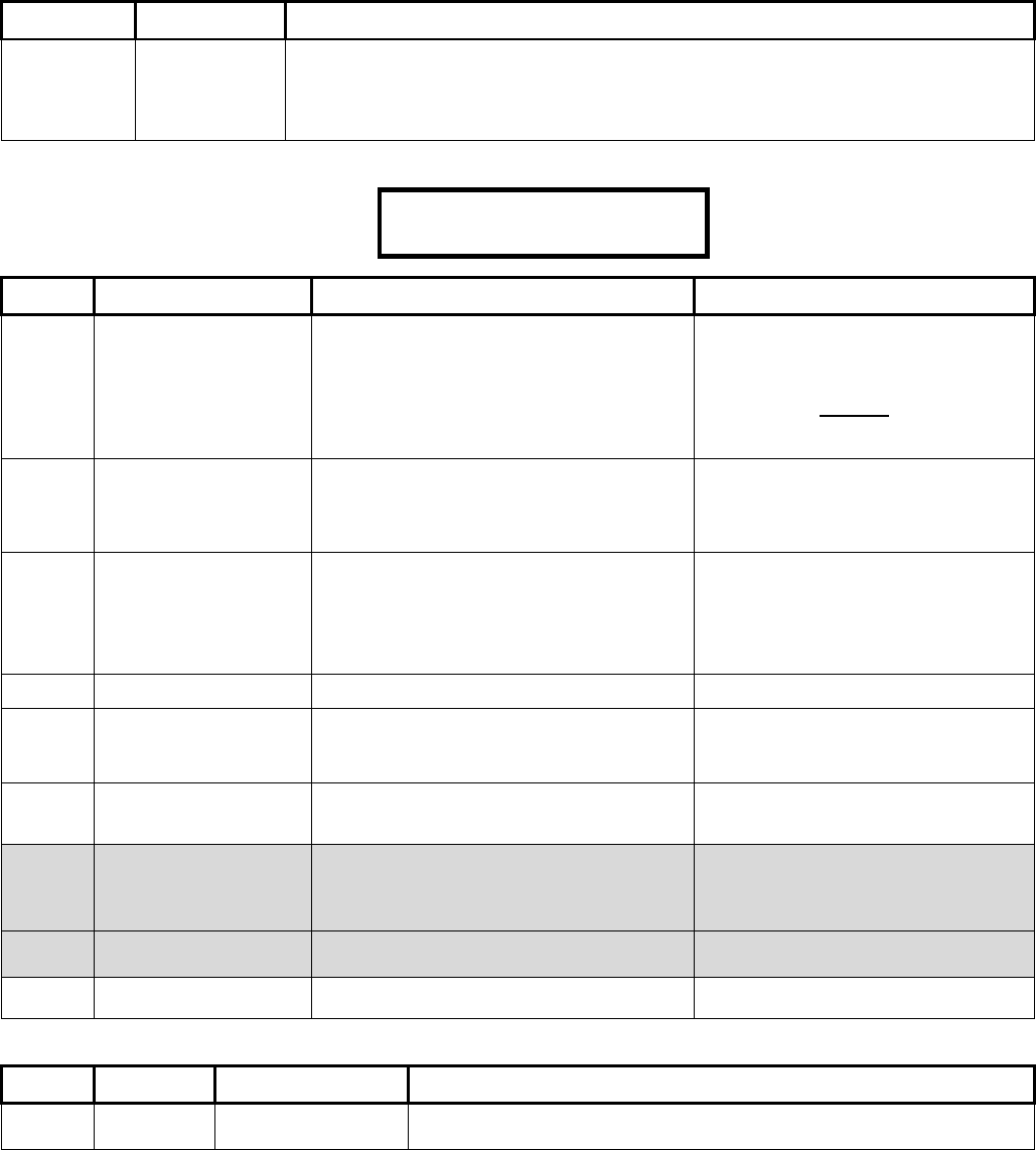
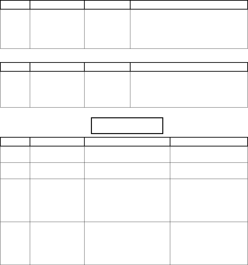
LCD Keypad Screen
When the control box
tamper is activated, a
service user has
Service
Enter PIN: _ _ _ _
the authority to access system programming.
Using the left and right
arrow screen scrolling
keys on the keypad
Menu Options
◄ Config ► Ok
scroll the menus until Config is displayed. Press
Ok. “Config method” will display. Select “Advanced” with
the arrow keys and press Ok.
The screen that begins
Advanced programming
will display.
S001:00 E-05Q34
OK +Group-
S001:00: this is the start of the System program section.
Each of the program sections begin with a letter. The
next 3 digits (e.g. “001”) represent the first program
section for System programming. The next 2 digits (e.g.
“00” after the colon) represent a sub programming
section of this main system program section.
The letters for each of the programming sections are: S:
System; A: Areas; M: Modules; P: Input Points; E:
Equipment/Pseudo points; B: Programmable Outputs;
L: Authority Levels; I: ProfIle; W: User Edit; U: Users;
H: Holidays; D: Schedules; T: Custom Pt Type; R:
DooRs; G: Area Group; Z: Shared Data Groups (Users
and Holidays).
E-05Q34: the version of the main controller firmware.
+Group- : Using the middle or right down arrow keys
this term’s arrows are pointing to will scroll forward or
backward through the various program sections
(Groups). It will change the program section letter &
display that section’s program selections for the same
programming and sub programming section.
OK: Pressing the button below OK will enter the
programming section displayed.
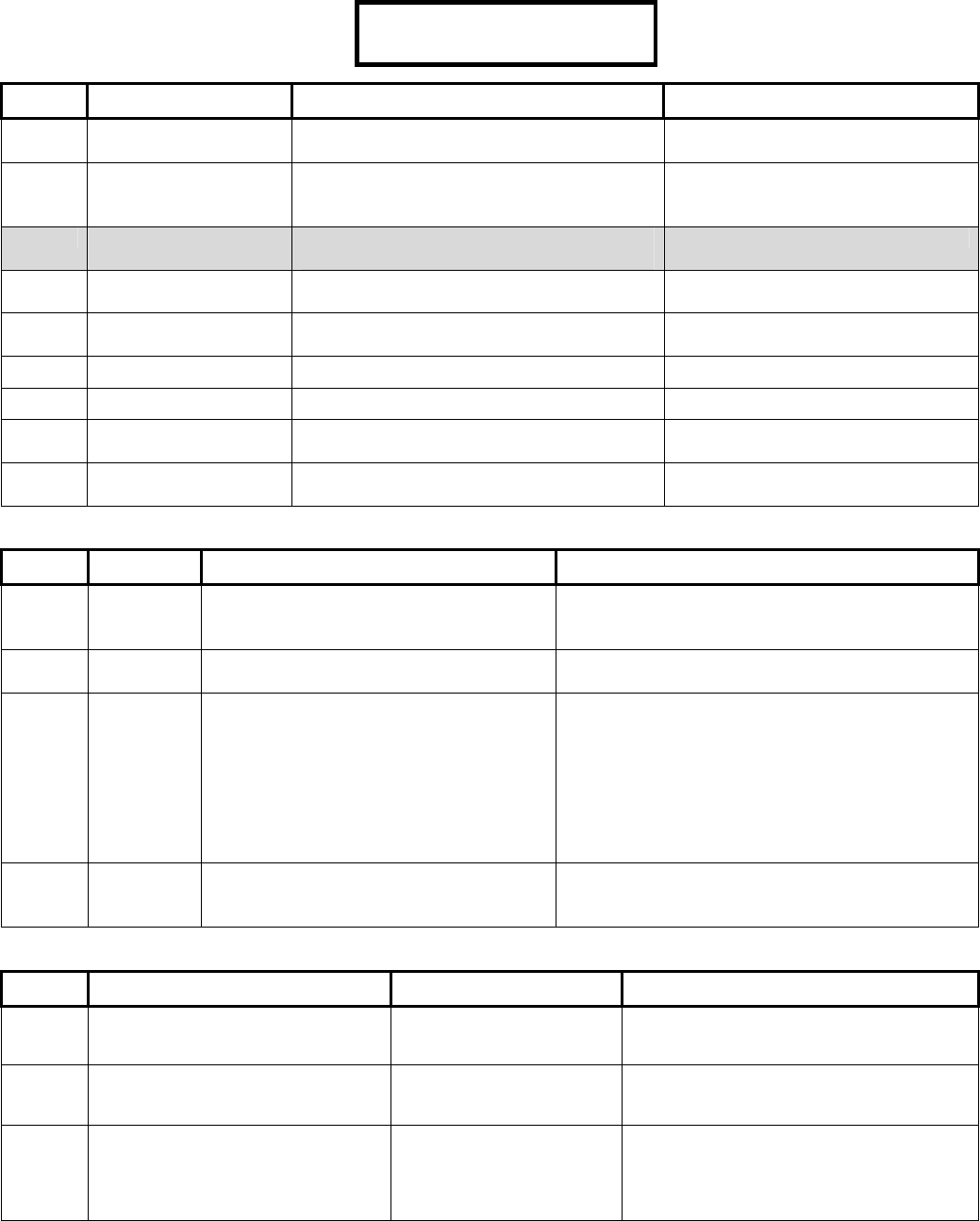
A sub programming
section can display
several defaulted
□.□.0.□.1.□ □
Save S002:1
selections that will affect the way the system operates.
These selections can be changed to customize the
system operation. A box “ □ ” represents that a
programming selection has been disabled. A check mark
“ “ means that it is enabled. With the cursor flashing
under a specific selection, the selection can be toggled
back and forth from a box to a check mark by pressing
any key on the keypad.
Other entries are numerical and with the cursor flashing
under them they can be changed by pressing the
desired number entry on the keypad from available
selections. When entering a sub programming section
and all its various selections, the section displayer (e.g.
S002:1) appears in the lower right corner of the
screen.
When a selection has bee changed, always press the
button below Save to retain the change.
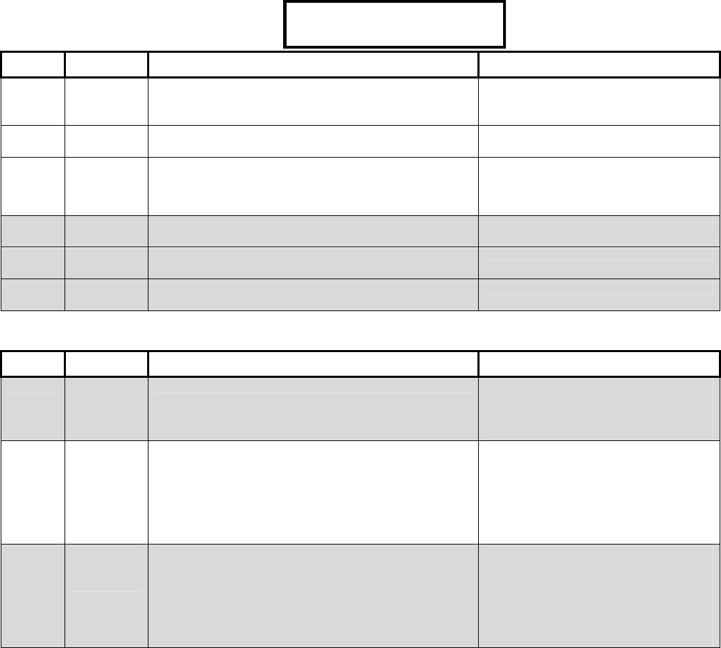
A program section with a
down arrow in its section
displayer means if the
201.01.01. . . .
Save ? P0010
down arrow button beneath it is pressed, the screen will
change to the next input, output etc. and the same
program selections for it.
Pressing the keypad button below “ ? “ when it
displays in a screen, will cause a momentary
screen to display related information. E.g. an input
or output number associated with a module will
display the module’s number (i.e. module # XX),
what type it is (e.g. Point Expander module), the
module’s serial number and its input or output
number range. Pressing the button below ““ will
display information about a specialized module
such as RF wireless or a printer module.
2 Monitor xL™ Advanced Installation Guide 21-3602E rev1.5
Advanced Program Sections, Sub Program Sections and Selections
NOTE: For quick reference to locate Advanced Programming Section Selections, consult the Index at the back of this
manual.
WARNING: Access, Elevator and Suite Security selections are only available with the addition of the
“Feature Expansion Board” to the System.
Programming selections whose boxes are grey are not available for this version.
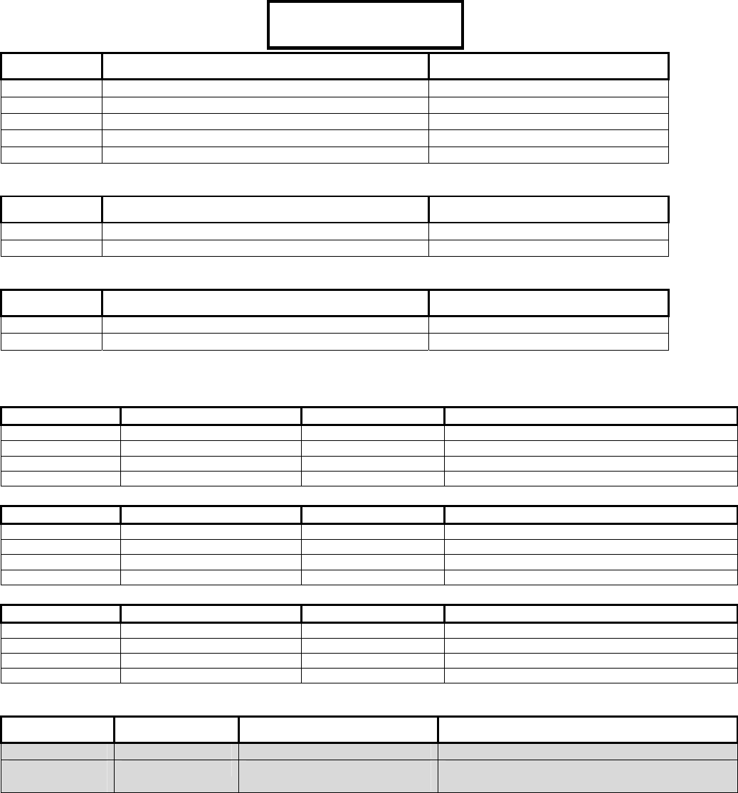
System Global Timer Delay Codes
00: undefined;
01: 1 sec;
02: 2 sec;
03: 3 sec;
04: 5 sec;
05: 10 sec;
06: 15 sec;
07: 20 sec;
08: 30 sec;
09: 45 sec;
10: 60 sec;
11: 90 sec;
12: 2 min;
13: 3 min;
14: 5 min;
15: 10 min;
16: 15 min;
17: 20 min;
18: 30 min;
19: 45 min;
20: 60 min;
21: 90 min;
22: 2 hr;
23: 4 hr;
24: 6 hr;
25: 8 hr;
26: 10 hr;
27: 12 hr;
28: 16 hr;
29: 20 hr;
30: 1 day;
31: 1 week
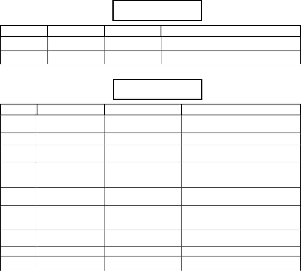
Program Section: S001 (System Wide Selections)
S00100 Keypad Selections
(left to right on keypad screen) Example:
Default Name Selections Description
14
(5 min)
Burglary Siren Time Siren Time: See Timer Delay Codes Chart 00 =
disabled to 22 = 2 hrs max.
How long a siren in the system will
sound.
(UK ACPO = 16: 15 min)
(European = 17: 20 min)
03 Number of panel
inputs
Multiply entries by four (4)
E.g. 4 X 1 = 4. Enter “1” for 4 inputs.
4 X 2 = 8. Enter “2” for 8 inputs.
4 X 3 = 12. Enter “3” for 12 inputs.
4 X 4 = 16. Enter “4” for 16 inputs.
4 X 5 = 20. Enter “5” for 20 inputs.
MONITOR Panel default = 2
For VBUS input boards connected to the
main controller VBUS port. 20 inputs
maximum. 12 on main board and 1
VBUS input boards possible.
01 Number of panel
outputs
Multiply entries by four (4)
E.g. 4 X 1 = 4. Enter “1” for 4 outputs.
4 X 2 = 8. Enter “2” for 8 outputs.
4 X 3 = 12. Enter “3” for 12 outputs.
4 X 4 = 16. Enter “4” for 16 inputs.
4 X 5 = 20. Enter “5” for 20 inputs.
4 X 6 = 24. Enter “6” for 24 inputs.
4 X 7 = 28. Enter “7” for 28 inputs.
MONITOR Panel default = 2
(UK ACPO = 3: 12 outputs)
For VBUS output boards or modem
output boards connected to the main
controller VBUS port. 26 outputs
maximum. Program for 28 outputs and
skip outputs 27 – 28. 2 relays on main
board and 2 VBUS output boards
possible or 1 VBUS output board and
one 8 output modem board. Also see
S001:06 -07.
0 Panel Type 0 = Monitor xL, 1 = MONITOR ISM, 2 = Future, 3
= Future.
1 Module Bus (SNAPP)
Baud Rate
0 = Auto Minimum (19K2), 1 = Auto Maximum
38K4
The communications speed between the
main panel and the expansion modules.
1 Suite Security
(Condo) Baud Rate
NOTE: This feature is only
available with the addition of
the Director Software and
Feature Expansion Board.
0 = Auto Minimum (19K2), 1 = Auto Maximum
(38K4) 2 = 9600 (Auto Minimum), 3 = future.
The communications speed between the
main panel and the Suite Security
modules.
0 Fallback Users 0: No access; 1: All readable tokens; 2: All with
valid site code; 3: 10 fallback users
Specific Cards granted access if door
controller is unable to access the panel
database. (UK ACPO = 3)
14 ·
0
3 ·
0
1 ·
0
·
1
·
1
·
0
Save S00100
21-3602E rev1.5 Monitor xL™ Advanced Installation Guide 3
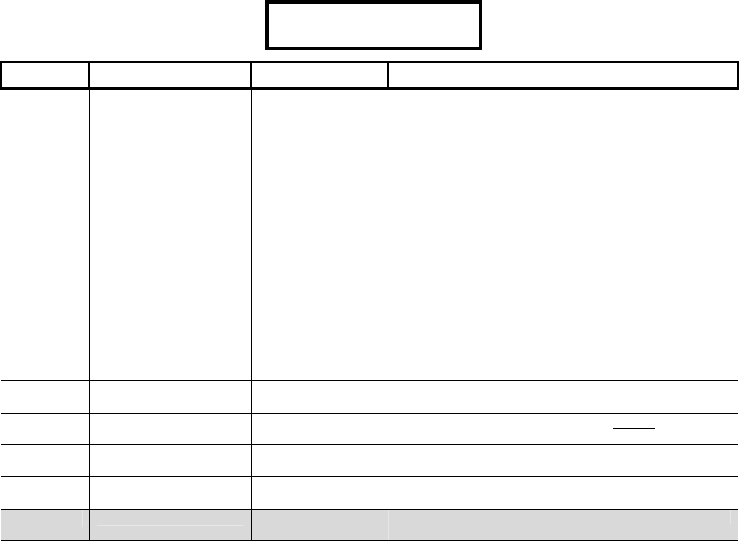
S00101 Keypad Selections (left to right on keypad screen)
Default Name Selections
WELCOME
(16 available
characters)
Main screen
message
A greeting message that rotates with any other main screen messages. It can be customized
with the cursor under a letter or in a blank space and pressing the desired keypad button to
enter a particular letter/number. Use the left and right arrow keys to maneuver back and forth.
Use the underscore key “ _ “ on the keypad to insert a space or clear a character.
(UK ACPO = CHUBB SECURITY)
S00102 Keypad Selections
(left to right on keypad screen) Example:
Default Name Selections Description
000000 Panel Unique ID
(Panel Code, System ID)
– A (non-zero) number to identify the
panel, site, or account to the Director
software. For an existing system to be
synchronized with the Director software,
this must be a non-zero value set here
to match the "Panel Code" in the
software.
(no) Unlock Doors on Fire
Alarm
NOTE: This feature is only
available with the addition of the
Feature Expansion Board.
= Global Unlock □(no) Will a fire alarm unlock all controlled
doors in the facility?
(no) Auto Update Card
Version
NOTE: This feature is only
available with the addition of the
Feature Expansion Board.
Allow automatic version update.
□ Disable update
Whether or not replacement cards are to
be granted entry, and the system is to
be updated with the higher version
number automatically. (This setting
refers to fixed-ID cards with a version
number).
(no) Delay Screen (yes) □(no) (UK ACPO = yes)
(no) Fast Restore (yes) □(no) If a point restore is to be sent within 1
min. (as opposed to siren time-out).
UK ver. is 12 sec.
(UK ACPO = yes)
(no) Ring Back Required (yes) □(no) If monitoring station will cause keypad
tone & siren to confirm area arming (for
UL).
(no) Suite Secuirty System
NOTE: This feature is only
available with the addition of the
Director Software and Feature
Expansion Board.
0 = Normal, 1 = Different users per area.
(no) Single Panel (yes) □(no) Yes = Single Panel
No = Multi Panel connection.
(no) Enable Wall Tamper (yes) □(no) Main control box back tamper.
(UK ACPO = yes)
S00103 Keypad Selections (left to right on keypad screen)
Default Name Selections Description
000000 3r
d
Party
Password
– This is a security ‘key’ that blocks an unauthorized connection to this panel
i.e., by a PC running another copy of the Director software.
000000 ·
Save S00102
4 Monitor xL™ Advanced Installation Guide 21-3602E rev1.5
S00104 Keypad Selections
(left to right on keypad screen) Example:
Default Name Selections Description
00 Confirmed Alarm Time
Out
Time table codes. (UK ACPO = 18)
0 Maximum Number of
Alarms per Point
Arming State
0 = All, 1 = 1, 2 = 2, 3 = 3 Primarily for
European Users.
(UK ACPO = 3)
0 Menu Navigation 0 = Standard, 1 = Ok-SOFT-3, 2 = Ok-
SOFT-1, 3 = future.
0 LCD Menu Style 0 = Standard, 1 = Ok-SOFT-3, 2 = Ok-
SOFT-1, 3 = future.
0 Unconfirmed Reset
Mode
0 = None, 1 = Follow Confirm Alarm, 2 =
Include Master, 3 = future.
(no) Confirm Reset Service (yes) □ (no) (UK ACPO = yes)
(no) Confirm Reset Master (yes) □ (no)
(no) Confirm Reset
Challenged PIN.
(yes) □ (no)
(no) Confirm Reset using
Remote
(yes) □ (no)
S00105 Keypad Selections (left to right on keypad screen)
Default Name Selections Description
01100 AC
Reference
Voltage
– Main panel electrical mains operation.
E.g. 01100 = 110.0 Decivolts
(UK ACPO = 02200)
070 Battery
Size
Amp hours X 10
E.g. display as 7.0
(UK ACPO = 17.0)
0 AC Sync 0=60 Hz, 1=50 Hz, 2=No sync required,
3=DC supply
Synchronization with AC line to maximize internal clock
accuracy. With an unstable AC source, select "2: AC-
No Sync" ('AC failure' will be reported if the frequency
drops below 12.5 Hz). With a DC source, be sure to
disable E003 (AC Trouble) under "Equipment
Settings".
DC supply option will not detect power failure condition
and will not have a time base sync
(UK ACPO = 1)
0 AC
Brownout
Mode
0=None, 1=Local alarm, 2=Alarm+report,
3=Report only
S00106 Keypad Selections (left to right on keypad screen)
Default Name Selections Description
001 VBUS Panel Output Base See: Main Panel Output
Examples: next
What number the outputs that will be used on
the main controller’s VBUS connection will
start at.
001 Paging Output Base See: Main Panel Output
Examples: next
What number the outputs that will be used on
the paging system will start at.
Also see S005:08, 09
001 Output Base for:
World Wide Modem with 8 output STU
REDCARE interface or 8 output STU
REDCARE interface
STU = Subscriber Terminal Unit
See: Main Panel Output
Examples: next
What number the outputs that will be used
with the main control board output plug in
boards will start at.
(UK ACPO = 003)
00·
0
·
0
·
0
·
0
· ·
Save S00104
21-3602E rev1.5 Monitor xL™ Advanced Installation Guide 5
Main Panel Output Examples: If the main panel’s 2 relay outputs have a base of 1; this is the base number they
start at. Assigning outputs to them would require the minimum amount of 4. Outputs 3 and 4 are not used. The next
set of outputs could be the World Wide Modem with 8 output STU plugged in to the main controller modem port. Its
base number would then be 5. 8 outputs assigned to it would make its output range 5 to 12. Next would be if an 8
output VBUS board was connected to the main controller VBUS port. Its base number would be 13 and assigned 8
outputs making its range 13 – 20. Instead of modem outputs and one VBUS output board, 2 VBUS output boards
could be used in the same way. More outputs can follow through module programming after the main controller or
pager outputs can be added next. The pager output’s base number would then be 21 and could be assigned 4
outputs that would be 21 – 24 (maximum 16 pager outputs). Then output ranges for regular modules after the ones
assigned to the main control unit can be done.
S00107 Keypad Selections
(left to right on keypad screen) Example:
Default Name Selections Description
00 VBUS
Panel #
Outputs
0=0, 1=2, 2=4, 3=6, 4=8, 5=10, 6=12, 7=14,
8=16,
00 Paging #
Outputs
0=0, 1=2, 2=4, 3=6, 4=8, 5=10, 6=12, 7=14,
8=16
Also see S005:08, 09
0 Main Panel
Plug In
Board
Outputs
0=0, 1=2, 2=4, 3=6, 4=8 (UK ACPO = 4)
0 VBUS
Mode
0 – 3 future
0 VBUS
Speed
0 – 3 future
Allow Port
Expanders
(yes) □ (no)
S00108 Keypad Selections (left to right on keypad screen)
Default Name Selections Description
000 Delinquent
Arming
Threshold
0 – 127 days Delinquent Account Protection.
Tracks panels that have not been
operated for the number of days
selected.
0 Area
Group
Mode
0=By area arming only
1=User Groups Only: users can turn on protection to all
groups of areas they are authorized for.
2=Manual + User Groups: users can turn on protection
to all groups of areas they are authorized for, individual
area groups or areas.
3=Remote Group or Area or Local Group
Used in association with the Group Area
program section G00100, the Arm/Disarm
Map, M00103, Authority Profiles and
Authority Levels for a user to have control over
multiple areas.
Report
Delinquent
Arming
(yes) □ (no) Delinquent Account Protection.
Reports panels that have not been
operated for the number of days
selected in Delinquent Arming
Threshold.
(Will not apply if Delinquent Arming Threshold
= 000)
0
0
·
0
0·
0
·
0
·
0
· ······
Save S00107

6 Monitor xL™ Advanced Installation Guide 21-3602E rev1.5
S00200 Keypad Selections (left to right on keypad screen)
Default Name Selections Description
0 Operation Mode Enter from right to left.
0 - Standard version
1- European with modem support
2- UK (DD243) (ACPO)
3-7 – for future extension
(UK ACPO = 2)
03 Feature Set 1-14 from the following table. This setting determines the system
capacity.
Feature Set Levels and Panel Capacities:
Feature 01 02 03 04 05 06 07 08 09 10 11 12 13 14
Users 20 20 100 100 300 1,000 1,000 1,000 2,000 4,000 10,000 10,000 20,000 20,000 20,000 64,000 64,000
Doors 0 16 0 16 4 16 16 32 32 32 32 32 32 32 32 32 32
Schedule 50 50 50 50 50 50 100 100 100 100 250 250 250 250 250 250 250
A
uthority 30 30 30 30 30 30 100 100 100 100 500 500 500 1,000 1,000 1,000 1,000
Profile 60 60 60 60 60 60 200 200 200 200 750 750 1,000 1,000 1,000 1,000 1,000
User Edit 10 10 10 10 10 10 50 50 50 50 750 750 1,000 1,000 1,000 1,000 1,000
Floor
A
uthority 0 0 0 0 0 0 0 50 50 50 100 100 100 100 100 100 100
Point 256 256 256 256 256 256 256 256 256 256 256 256 256 256 256 256 256
Outputs 128 128 128 128 128 128 128 128 128 128 128 128 128 128 128 128 128
A
rea 16 16 16 16 16 16 16 16 16 16 16 16 16 16 16 16 16
Log 1,024 1,024 1,024 1,024 1,024 1,024 2,048 2,048 2,048 2,048 8,192 8,192 8,192 16,364 16,364 65,536
32,768
(ISM),
16,364
(xL)
Module* 24 24 24 24 24 24 24 24 24 24 24 24 24 24 24 24 24
Custom
Point 20 20 20 20 20 20 20 20 20 20 20 20 20 20 20 20 20
Pseudo
Point 16 16 16 16 16 16 16 16 16 16 16 16 16 16 16 16 16
Holiday 50 50 50 50 50 50 50 50 50 50 50 50 50 50 50 50 50
Suite
Security 0 0 0 0 0 0 0 60 60 60 60 60 60 60 60 60 60
Floor 0 0 0 0 0 0 0 124 124 124 124 124 124 124 124 124 124
* Plus capacity for one temporary service LCD keypad for connecting to the module bus at the main controller.
Additional RAM must be added with Feature Set 4 and greater. The “Feature Expansion Board” must be added to the
system.

21-3602E rev1.5 Monitor xL™ Advanced Installation Guide 7
S00201 Keypad Selections
(left to right on keypad screen) Example:
Default Name Selections Description
0 User Logon
Mode
0 = Standard user ID logon or Card Number logon:
1 = 4 digit, 2 = 5 digit, 3 = 6 digit, 4 = 7 digit, 5 = 8
digit
6 = 9 digit, 7 = 10 digit
Users can enter their card # at LCD
keypad & keypad readers.
0 Service Pin Mode 0: Permanent
1: Temporary
2 = 6 Digit Pin of the day
“6 digit pin of the day” service PIN mode
related to: “Dealer ID” S002:04. Contact
the Central Monitoring facility and provide
them with this number to obtain the required
PIN for the current day. While in this mode,
any manually configured service PIN will be
ignored.
0 Escort Required
Mode
0 = escorted by users with Escort authority.
1 = escorted by Permanent Users.
2 = escorted by a Permanent or Temporary user.
Escort type a Visitor is accompanied by.
(no) 5 Digit PIN (yes) □ (no) Whether or not user PIN entry will
require 5 digits.
(yes) PIN Duress (yes) □ (no) Refers to users reversing the last 2
digits when entering their PIN at a
keypad to indicate they are being forced
to enter (or forced to login at a keypad).
Note: Applicable reader(s) must be set
for "Card and/or PIN" entry.
(UK ACPO = no)
(no) Access Panic
Tokens
NOTE: This feature is
only available with the
addition of the Feature
Expansion Board.
(yes) □ (no)
(no) Blind Card
Re-enrollment
NOTE: This feature is
only available with the
addition of the Feature
Expansion Board.
(yes) □ (no) Meaningful only if using card enabling
feature
(yes) Supports
Intrusion
(yes) □ (no) System Type. Viewing only.
Dependent on setting in Director
Software.
(yes) Supports Access
NOTE: This feature is
only available with the
addition of the Feature
Expansion Board.
(yes) □ (no) System Type. Viewing only.
Dependent on setting in Director
Software.
(yes) Supports Central
Station
(yes) □ (no) System Type. Viewing only.
Dependent on setting in Director
Software.
(no) Supports: Suite
Security Modules
NOTE: This feature is
only available with the
addition of the Director
Software and Feature
Expansion Board.
(yes) □ (no) System Type. Viewing only.
Dependent on setting in Director
Software.
(no) Supports:
Elevators
NOTE: This feature is
only available with the
addition of the Director
Software and Feature
Expansion Board.
(yes) □ (no) System Type. Viewing only.
Dependent on setting in Director
Software.
0·0·0· ·
Save S00201

8 Monitor xL™ Advanced Installation Guide 21-3602E rev1.5
S00202 Invalid Cards and PINs Detection Selections
Keypad Selections
(left to right on keypad screen) Example:
Default Name Selections Description
12 Reset
Timeout
NOTE: The card
feature is only
available with the
addition of the
Feature Expansion
Board.
1 – 31 (Delay Table), 12 = 2min
(0 is meaningless and is not used)
The period of time required before there
are no further invalid PIN/cards and a
“Invalid PIN/Card Condition” resets.
12 Lockout Time
NOTE: This feature
is only available
with the addition of
the Feature
Expansion Board.
1 – 31 (Delay Table), 12 = 2min
(0 is meaningless and is not used)
The length of time a user is locked out of
the system after X number of invalid
PIN/Card tries are made, even if a valid
try is made.
09 Maximum
number of
invalid cards
NOTE: This feature
is only available
with the addition of
the Feature
Expansion Board.
00 = 1 invalid card, 01 = 2, 02 = 3, etc to 63 = 64 The amount of invalid cards used before
an “Invalid card Condition” occurs.
5 Maximum
number of
invalid PINs
0 = 1 invalid PIN, 1 = 2, 2 = 3, 3 = 4, 5 = 6, 7 = 8 The amount of invalid PINs used before
an “Invalid PIN Condition” occurs.
(European = 02)
0 Invalid card
detection type
NOTE: This feature
is only available
with the addition of
the Feature
Expansion Board.
0 = invalid card detection is turned off, 1 = detect invalid
cards, 2 = 1 + “high risk denied” cards, 3 = 1 & 2 + lower
risk denied cards (all denied).
Invalid Card Examples: wrong
version number, wrong site code,
card not in database. High Risk
Denied card examples: time expired,
interlock violation, reader locked out,
no area authority. Low Risk Denied
card examples: no area disarming
authority, wrong class, timeouts,
anti-passback violations.
3 Number of
different
users for
global lockout
NOTE: The Card
feature is only
available with the
addition of the
Feature Expansion
Board.
0 =4 different invalid users, 1 = 6, 2 = 8, 3 = 10. Defines how many different users have
to be individually in an invalid PIN or
unauthorized card lockout condition
before a global lockout will occur for all
users.
(no) Transmit
global lockout
alarm
NOTE: This feature
is only available
with the addition of
the Feature
Expansion Board.
(yes) □ (no) = invalid card and/or PIN causes local
warning only.
= local warning & reports to the
monitoring station.
12·
1
2·
0
9
·
5
·
0
·
3
·
Save S00202
21-3602E rev1.5 Monitor xL™ Advanced Installation Guide 9
S00203 Keypad Selections (left to right on keypad screen)
Default Name Selections Description
10
(60sec)
Point Reset
Time
Delay table. Delay time.
(UK ACPO = 02) (European = 04)
0 Language Set 0=Eng,Fre,Dut,Spa, 1=Eng,Slk,Slk,Slk, 2=Future,
3=Future
0 Remote FW
Down/Up
Load
0 = Allowed, 1= Must be authorized
0 Arming Rules 0 = Normal operation. Entry/Exit keypad standard
tone.
1 = Disarm to off by token. Entry/Exit keypad
standard tone.
2 = Constant keypad Entry/Exit tone
3 = Disarm to off by token. Constant keypad
Entry/Exit tone.
Standard Tone = intermittent
Entry/Exit tone, constant alarm tone.
Constant Tone = constant Entry/Exit
tone, intermittent alarm tone.
Standard keypad tones are
reversed.
S00204 Keypad Selections (left to right on keypad screen)
Default Name Selections Description
_ _ _ _ _ Keypad Lock Code Equivalent of RF reader lock code for
new RF keypads only.
S00205 Keypad Selections (left to right on keypad screen)
Default Name Selections Description
_ _ _ _ _ Dealer ID 0 – 65535 This setting is used with the “6 digit pin of the day” service PIN mode. Contact the
monitoring station and provide them with this number to obtain the required PIN
for the current day. While in this mode, any manually configured service PIN will
be ignored. Related: “Service PIN Mode” is the 2nd field under S002:1.
S00300 Primary Card Format—Site Code Checking
WARNING: S00300 – S00305 Access Control related selections are only available with the addition of
the “Feature Expansion Board”.
Keypad Selections (left to right on keypad screen) Example:
Default Name Selections Description
(no) Check for Site Code (yes) □ (no) Whether or not primary-format tokens must have a
specific site code to be granted entry.
06 Site Code Position 1 – 40 The position of the 1st digit for the site/system code on
these access tokens.
Position value changes depending on site code length.
10 Site Code Length 1 – 16 The length of the site code for primary-format tokens
(number of digits).
Site code when represented as a digital #. Can not
exceed 4 digits.
S00301 Primary Card Format—Site Codes
Keypad Selections (left to right on keypad screen)
Default Name Selections Description
0000 1st Site Code Value 0000 – 9999 The 1st of up to three site/system codes that can be encoded within
access tokens to be used at the site.
0000 2nd Site Code Value 0000 – 9999 The 2nd of up to three site/system codes that can be encoded
within the access tokens to be used at the site.
0000 3rd Site Code Value 0000 – 9999 The 3rd of up to three site/system codes that can be encoded
within the access tokens to be used at the site.
If site code checking is enabled for the primary card/token format cards encoded with any one of up to three site code values can be used at the
site. (All other cards will be globally denied access.)
·
0
6·
1
0···········
Save S00300

10 Monitor xL™ Advanced Installation Guide 21-3602E rev1.5
S00302 Primary Card Format—Version Number
Keypad Selections (left to right on keypad screen)
Default Name Selections Description
(no) Check for
Version No. (yes) □ (no) Whether or not primary-format
tokens will be checked for a current
version number.
02 Version No.
Position
1 – 40 The position of the 1st digit for the
version number on these access
tokens.
04 Version No.
Length
1 – 8 The length of the version number for
primary-format tokens (number of
digits).
This feature requires V1.5 door/elevator controller firmware.
S00303 Primary Card Format—Basic Settings
Keypad Selections
(left to right on keypad screen) Example:
Default Name Selections Description
16 ID Number
Position
01 – 40 The position of the 1st digit for the
ID number on primary-format access
tokens.
20 ID Number
Length
01 – 32 The length of the card ID-number for
primary-format tokens.
36 No. of Bits /
Chars
01 – 40 The total number of bits (Wiegand)
or characters (Magstripe) in the card
data.
8 Bits per
Character
01 – 08 The number of bits used to
represent each character (for
magnetic stripe cards).
2 Card/Token
Format
0=none, 1=future (dallas), 2=Weigand, 3=Magstripe The basic type of card or token
associated with the primary card
format settings.
32-Bit / 9-Digit Card IDs: This requires V1.5 door/elevator controller firmware.
S00304 Odd Parity Information (Primary)
Keypad Selections (left to right on keypad screen)
Default Name Selections Description
36 Odd Parity Position 1 – 40 The position of the odd-parity 'checksum'.
18 Odd Parity Start 1 – 40 This is the position of the first data-bit to be included for odd-parity checking.
18 Odd Parity Length 0 – 40 If either the odd parity length = 0 or even parity length = 0, then parity will not
be checked.
Odd/Even Parity checking: This feature (which applies only to Wiegand-format cards) helps prevent card misreads.
To disable parity checking: Set the ‘Parity Length’ to 0 (zero).
S00305 Primary Card Format—Even-Parity Checking
Keypad Selections (left to right on keypad screen)
Default Name Selections Description
01 Even Parity Position 1 – 40 The position of the even-parity 'checksum'.
02 Even Parity Start 1 – 40 This is the position of the first data-bit to be included for even-parity
checking.
18 Even Parity Length 0 – 40 This is the number of bits to be included for even-parity checking. If either
the odd parity length = 0 or even parity length = 0, then parity will not be
checked.
Odd/Even Parity checking: This feature (which applies only to Wiegand-format cards) helps prevent card misreads.
To disable parity checking: Set the 'Parity Length' to 0 (zero).
16·
2
0·
3
6·
8
·
2
·······
Save S00303

21-3602E rev1.5 Monitor xL™ Advanced Installation Guide 11
S00400 Secondary Card Format—Site Code Checking
WARNING: S00400 – S00405 Access Control related selections are only available with the addition of
the “Feature Expansion Board”.
Keypad Selections
(left to right on keypad screen) Example:
Default Name Selections Description
(no) Check for Site
Code (yes) □ (no) Whether or not secondary-format tokens must have a specific
site code to be granted entry.
02 Site Code
Position
1 – 40 The position of the 1st digit for the site/system code on these
access tokens.
Position value changes depending on site code length.
08 Site Code
Length
1 – 16 The length of the site code for secondary-format tokens (number
of digits).Site code when represented as a digital #. Can
not exceed 4 digits.
S00401 Secondary Card Format—Site Codes
Keypad Selections (left to right on keypad screen)
Default Name Selections Description
0000 1st Site Code
Value
0000 – 9999 The 1st of up to three site/system
codes that can be encoded within
access tokens to be used at the site.
0000 2nd Site Code
Value
0000 – 9999 The 2nd of up to three site/system
codes that can be encoded within
access tokens to be used at the site.
0000 3rd Site Code
Value
0000 – 9999 The 3rd of up to three site/system
codes that can be encoded within
access tokens to be used at the site.
If site code checking is enabled for a secondary card/token format, cards encoded with any one of up to three site code values can be used at the
site. (All other cards will be globally denied access.)
S00402 Card Version-Information (Secondary)
Keypad Selections (left to right on keypad screen)
Default Name Selections Description
(no) Check for
Version No. (yes) □ (no) Whether or not secondary-format
tokens will be checked for a current
version number.
02 Version No.
Position
1 – 40 The position of the 1st digit for the
version number on these access
tokens.
04 Version No.
Length
1 – 8 The length of the version number for
secondary-format tokens (number of
digits).
This feature requires V1.5 door/elevator controller firmware.
·
0
2
·
0
8···········
Save S00400

12 Monitor xL™ Advanced Installation Guide 21-3602E rev1.5
S00403 Secondary Card Format—Basic Settings
Keypad Selections
(left to right on keypad screen) Example:
Default Name Selections Description
10 ID Number
Position
1 – 40 The position of the 1st digit for the
ID number on secondary-format
access tokens.
16 ID Number
Length
1 – 32 The length of the card ID-number for
secondary-format tokens.
26 No. of Bits /
Chars
1 – 40 The total number of bits (Wiegand)
or characters (Magstripe) in the card
data.
8 Bits per
Character
1 – 8 The number of bits used to
represent each character (for
magnetic stripe cards).
2 Card/Token
Format
0=none, 1=future (dallas), 2=weigand, 3=mag The basic type of card or token
associated with the secondary card
format settings.
32-Bit / 9-Digit Card IDs: This requires V1.5 door/elevator controller firmware.
S00404 Secondary Card Format—Odd-Parity Checking
Keypad Selections (left to right on keypad screen)
Default Name Selections Description
26 Odd Parity Position 1 – 40 The position of the odd-parity 'checksum'.
14 Odd Parity Start 1 – 40 This is the position of the first data-bit to be included for odd-parity
checking.
12 Odd Parity Length 0 – 40 If either the odd parity length = 0 or even parity length = 0, then parity will
not be checked.
Odd/Even Parity checking: This feature (which applies only to Wiegand-format cards) helps prevent card misreads.
To disable parity checking: Set the 'Parity Length' to 0 (zero).
S00405 Secondary Card Format—Even-Parity Checking
Keypad Selections (left to right on keypad screen)
Default Name Selections Description
01 Even Parity Position 1 – 40 The position of the even-parity 'checksum'.
02 Even Parity Start 1 – 40 This is the position of the first data-bit to be included for even-parity
checking.
12 Even Parity Length 0 – 40 This is the number of bits to be included for even-parity checking.
Odd/Even Parity checking: This feature (which applies only to Wiegand-format cards) helps prevent card misreads.
To disable parity checking: Set the 'Parity Length' to 0 (zero).
10·
1
6·
2
6·
8
·
2
····
Save S00403

21-3602E rev1.5 Monitor xL™ Advanced Installation Guide 13
S00500 Dialer Selections
Keypad Selections
(left to right on keypad screen) Example:
Default Name Selections Description
000000 Dialer
Account
Number
(Primary)
The system’s monitoring station receiver
number that will identify the premises.
1 Telco Modem
Type
1 = Bell 103, 2 = 8OP STU, 3 = WWMODEM
4 = WWMODEM 8OP STU
STU = Subscriber Terminal Unit
WW = World Wide
(UK ACPO = 2)
(European = 3)
0 Telco Alarm
Report Mode
0 = not used, 1 = primary, 2 = backup, 3 = dual
4 = future NOTE: “0” turns dialer off and clears all
the messages in the buffer
0 Telco Format 0 = SIA Level 2, 1 = CID, 2 = SIA Level 3
(future), 3 = Future
0 Telco
Sequence
0: ULC
1: UL compatible
2: Long
3: MONITOR Standard
(in Canada use 0 or 3)
Call Sequence Details: (P = Primary phone
# attempt; B = Backup phone # attempt)
0 (ULC): PPBBPPBB / delay 60 min /
PPBBPPBB / delay 60 min / PPBBPPBB /
delay 60 min / PPBBPPBB.
1 (UL): PPBBPPBBPB / delay 10 min.
2 (Long): PPPPBBBB / delay 10 min /
PPPPBBBB / delay 30 min / PPPPBBBB /
delay 60 min / PPPPBBBB /
delay 2 hours / PPPPBBBB.
3 (MONITOR Standard): PPBP / delay 5
min / PPBP / delay 10 min / PPBP / delay
30 min / PPBP / delay 60 min / PPBP /
delay 2 hours / PPBP.
(no) Telco –
prioritized
reporting
(yes) □ (no)
(yes) Telco – never
allow blind
dialing
(yes) □ (no) Dials regardless of detecting a dial
tone.
(UK ACPO = yes)
Telco = Telephone Company
S00501 Keypad Selections (left to right on keypad screen)
Default Name Selections Description
Blank
(16 characters)
Primary Phone Number – First Monitoring Station phone number the system will
dial to transmit reports.
The phone number can be preceded with P =pulse dialing (default), or T
=Tone dialing, and can include D =2 sec Delay, A =Star key (tone
dialing), # = Pound Sign (tone dialing), and/or W = Wait for second dial
tone. For Tone dialing, ensure the phone line supports this.
S00502 Keypad Selections (left to right on keypad screen)
Default Name Selections Description
Blank
(16 characters)
Secondary Phone
Number
– Second Monitoring Station phone number the system will
dial to transmit reports, if dialing the primary phone
number is unsuccessful.
The phone number can be preceded with P =pulse dialing (default), or T
=Tone dialing, and can include D =2 sec Delay, A =Star key (tone
dialing), # = Pound Sign (tone dialing), and/or W = Wait for second dial
tone. For Tone dialing, ensure the phone line supports this.
000000·1·0·0·0
Save S00500
14 Monitor xL™ Advanced Installation Guide 21-3602E rev1.5
S00503 Keypad Selections
(left to right on keypad screen) Example:
Default Name Selections Description
010 Telco Country Code 001 = Argentina …
088 = Yemen.
(UK ACPO = 085)
Country Codes
Argentina
Aamenia
Australia
Austria
Bahrain
Belgium
Brazil
Brunei
Bulgaria
Canada
Chile
China
Columbia
Croatia
Cyprus
1
2
3
4
5
6
7
8
9
10
11
12
13
14
15
Czech Republic
Denmark
Dubai
Egypt
El Savador
Equador
Estonia
European Union
Finland
France
Georgia
Germany
Great Britain
Greece
Guadalope
16
17
18
19
20
21
22
23
24
25
26
27
28
29
30
Guam
Hong Kong
Hungary
Iceland
India
Indonesia
Ireland
Isreal
Italy
Japan
Jordan
Kazahstan
Korea
Krgyzstan
Kuwait
31
32
33
34
35
36
37
38
39
40
41
42
43
44
45
Latvia
Lebanon
Liechtenstein
Luxembourg
Malaysia
Maldova
Malta
Martinique
Mexico
Moroco
Netherlands
New Zealand
Nigeria
Norway
Oman
46
47
48
49
50
51
52
53
54
55
56
57
58
59
60
Pakistan
Peru
Phillippines
Poland
Polynesia French
Portugal
Qatar
Reunion
Romania
Russia
Saudi Arabia
Singapore
Slovakia
South Africa
61
62
63
64
65
66
67
68
69
70
71
72
73
74
Spain
Sweden
Switzerland
Syria
Taiwan
Thailand
Tunisia
Turkey
Uae
Ukraine
United Kingdom
USA
Venezuela
Yemen
75
76
77
78
79
80
81
82
83
84
85
86
87
88
(no) Parallel STU 8OP
Supports Line Fail
(yes) □(no) World Wide Modem with 8 outputs for Redcare
connection monitors Redcare communication failure.
(UK ACPO = yes)
(no) Parallel STU 8OP Line
Fail Negative or
Positive Polarity
STU (Subscriber Terminal
Unit)
(yes) □(no) World Wide Modem with 8 outputs for Redcare
connection monitors Redcare positive or negative
communication failure.
□ (no) = Positive, (yes) = Negative
S00504 Keypad Selections (left to right on keypad screen)
Default Name Selections Description
000000 Dialer Account Number
(Daytime)
000 Dialer Daytime
Schedule
0 Dialer Daytime Mode 0=Not used, 1=Primary out of schedule
Daytime Schedule, 2/3=future
S00505 Keypad Selections (left to right on keypad screen)
Default Name Selections Description
Blank
(16 characters)
Daytime Phone Number – Daytime phone number the system will dial to transmit
reports.
The phone number can be preceded with P =pulse dialing (default), or T
=Tone dialing, and can include D =2 sec Delay, A =Star key (tone
dialing), # = Pound Sign (tone dialing), and/or W = Wait for second dial
tone. For Tone dialing, ensure the phone line supports this.
S00506 Keypad Selections (left to right on keypad screen)
Default Name Selections Description
Blank
(16 characters)
Telco Modem Init String –
Telco = Telephone Company
010········
Save S00503
21-3602E rev1.5 Monitor xL™ Advanced Installation Guide 15
S00507 Keypad Selections (left to right on keypad screen)
Default Name Selections Description
000000 SIP Account SIP = Security IP Receiver
0 HSC Mode 0= NotUsed, 1=SIP1, 2=SIP2, 3=HSC
POD (module)
HSC POD (High Security Communications) is
a proprietary communications of CSG
Security Inc. and not used in all markets.
0 HSC Timeout 0=90sec, 1=3min, 2=5min, 3=10min
0 HSC Full Report By
Area
0=full reporting always, 1=use area
emergency/full setting
0 SIP Baud Rate 0=150, 1=600, 2/3=future
0 HSC SIP Auto Set 0=manual settings, 1=SIP receiver sets all
variables
S00508 Keypad Selections (left to right on keypad screen)
Default Name Selections Description
0 Paging Mode 0 = None, 1 = Numeric SemaDigit w/ HS, 2 = Blind
SemaDigit, 3 = SemaPhone,future
Also see S001:06, 07
(no) Paging
Output Data
(yes) □ (no) Also see S001:06, 07
S00509 Keypad Selections (left to right on keypad screen)
Default Name Selections Description
Blank
(16 characters)
Paging Phone
Number
– Also see S001:06, 07
Paging phone number the system will dial to transmit reports.
The phone number can be preceded with P =pulse dialing (default), or T =Tone
dialing, and can include D =2 sec Delay, A =Star key (tone dialing), # = Pound Sign
(tone dialing), and/or W = Wait for second dial tone. For Tone dialing, ensure the
phone line supports this.
S00510 Keypad Selections
(left to right on keypad screen) Example:
Default Name Selections Description
00000 Main Control Board
Address
(Panel Serial Number)
Up to 5 digits, 0 = Undefined, 1 – 65534 =
Director software connection, 65535 = Special
Debug Mode
This is the serial number of the main
control board that is automatically
assigned.
0 Main Control Board
Connection Type
For viewing only. These selections are only done
at the Director software and not entered here.
They appear automatically in this selection when
the software first communicates with the main
controller board.
0: Direct-Cable
1: External Modem
2: Internal Modem – Bell 103
3: IP
4: Future
5: Internal Modem – World Wide
This specifies the type of connection
to a Director software PC.
0 Main Control Board
Reporting Mode
0: No Main Control Board reporting;
1: Blocks of 256 events;
2: Alarms (indiv. / small blocks)
Whether or not alarms or blocks of
events will be auto-transmitted to the
Director software.
Available with Monitor ISM using an
external modem or IP or with Monitor
xL using IP.
0 Main Control Board
Shared phone line
mode
0= Not shared, 1= Preemptive always, 2= User
intervention required w/ time, 3= Timed
0 Main Control Board
BaudRate
0=AutoMin(38K), 1= AutoMax (115K),
2=AutoMin (56K), 3=future
0
0
0
0
0·
0
·
0
·
0
·
0
·
0
·
Save S00510
16 Monitor xL™ Advanced Installation Guide 21-3602E rev1.5
0 Main Control Board
Config Dial Out
0 = No config dial out, 1= internal config dial
out, 2 = external config dial out, 3 = IP Configurations dial out from main
control board to Director software
PC.
Internal: main control board plug in
modem.
External: external modem
S00511 Keypad Selections (left to right on keypad screen)
Default Name Selections Description
Blank
(16 characters)
Director Software
Configurations Phone
Number
– Configurations phone number the system will dial to
contact the Director software PC and transmit system
programming.
The phone number can be preceded with P =pulse dialing (default), or T
=Tone dialing, and can include D =2 sec Delay, A =Star key (tone
dialing), # = Pound Sign (tone dialing), and/or W = Wait for second dial
tone. For Tone dialing, ensure the phone line supports this.
S00512 Keypad Selections (left to right on keypad screen)
Default Name Selections Description
Blank
(16 characters)
Main Control Board
Phone Number
– The phone number can be preceded with P =pulse dialing (default), or T
=Tone dialing, and can include D =2 sec Delay, A =Star key (tone
dialing), # = Pound Sign (tone dialing), and/or W = Wait for second dial
tone. For Tone dialing, ensure the phone line supports this.
S00513 Keypad Selections (left to right on keypad screen)
Default Name Selections Description
Blank
(16 characters)
Main Control Board
Modem Init String
–
S00514 Keypad Selections
(left to right on keypad screen) Example:
Default Name Selections Description
04 Main Control
Board Number
of Rings to
Answer
01 – 15 Used with North American or World
Wide Modems.
(UK ACPO = 02)
0 Suite Security
Telco Mode
NOTE: This feature is
only available with the
addition of the Director
Software and Feature
Expansion Board.
0 = report by area, 1 = report by DigitalAccountID
+ offset
0 Suite Security
Telco Reporting
NOTE: This feature is
only available with the
addition of the Director
Software and Feature
Expansion Board.
0=None, 1=Condos report alarms etc. over telco
dialer
(yes) Main Control
Board
Answering
Machine Defeat
(yes) □ (no) Used with North American or World
Wide Modems.
04·0·0········
Save S00514
21-3602E rev1.5 Monitor xL™ Advanced Installation Guide 17
(no) Main Control
Board Config
Callback Only
(yes) □ (no)
Telco = Telephone Company
S00515 Keypad Selections
(left to right on keypad screen) Example:
Default Name Selections Description
0 Telco Comms
Test Mode
0=fixed, 1=variable based on backup, 2=variable
based on any area out, 3=Daytime Schedule
00 Telco Normal
Comms Test
Delay
Delay table
00 Telco Backup
Comms Test
Delay
Delay table
00 Telco Comms
Test Hour
00 = midnight The time (hour) for communications
tests to occur.
00 Telco Comms
Test Minute
0-59 The time (min.) for comms tests to
occur.
0 Telco Comms
Test Day
0=Sun … The day for weekly comms tests to
occur.
Telco = Telephone Company
S0060-9 Ten FallBack Users Keypad Selections (left to right on keypad screen)
10 Fallback Users maximum.
Fallback User #1-10
0-9 00000
0 (UK ACPO) 00001
1 (UK ACPO) 00002
2 (UK ACPO) 00003
3 (UK ACPO) 00004
4 (UK ACPO) 00005
5 (UK ACPO) 00006
6 (UK ACPO) 00007
7 (UK ACPO) 00008
8 (UK ACPO) 00009
9 (UK ACPO) 00010
Up to 5 digits.
0= None, 001-64000.
Custom Circuit Types S00700, 04, 08, 12 Circuit Name
Keypad Selections (left to right on keypad screen)
Default Name Selections Description
0 Circuit Type 0 =Custom Type
1 = Normally Closed
2 = Normally Open
3 = Normally Closed Single Series EOL
4 = Normally Closed Single Parallel EOL
5 = Normally Open Single Series EOL
6 = Normally Open Single Parallel EOL
7 = Normally Closed Dual Type 1 EOL
8 = Normally Closed Dual Type 2 EOL
9 = Normally Open Dual Type 1 EOL
10 = Normally Open Dual Type 2 EOL
(16
characters)
Circuit Band
Name
0·
0
0
·
0
0
·
0
0
·
0
0
·
0
·
Save S00515
18 Monitor xL™ Advanced Installation Guide 21-3602E rev1.5
S00701, 05, 09,13 Circuit Band Definitions (Custom Resistor Values)
Keypad Selections
(left to right on keypad screen) Example:
Name Selections Description
Band 1 0=Normal, 1=Alarm, 2=Tamper, 3=unused
Band 2 0=Normal, 1=Alarm, 2=Tamper, 3=unused
Band 3 0=Normal, 1=Alarm, 2=Tamper, 3=unused
Band 4 0=Normal, 1=Alarm, 2=Tamper, 3=unused
Band 5 0=Normal, 1=Alarm, 2=Tamper, 3=unused
S00702, 06, 10, 14 Circuit Band Thresholds-1
Name Selections Description
Threshold 1 Split between band 1 and 2
Threshold 2 Split between band 2 and 3
S00703, 07, 11, 15 Circuit Band Thresholds-2
Name Selections Description
Threshold 3 Split between band 3 and 4
Threshold 4 Split between band 4 and 5
Default Circuit Values
Monitor xL
Type Name Bands Thresholds
S00700: 01 S00700: NC S00701: 0 1 1 1 1 S00702: 0132 1013 S00703: 1013 1013
S00704: 03 S00704: NC SERIES2K2 S00705: 2 0 1 1 1 S00706: 0298 0457 S00707: 1013 1013
S00708: 06 S00708: NO PARALL2K2 S00709: 1 0 2 2 2 S00710: 0298 0457 S00711: 1013 1013
S00712: 08 S00712: DUAL 2K2 EOL S00713: 2 0 1 2 2 S00714: 0132 0322 S00715: 0457 1013
Monitor ISM IMPORTANT: Custom circuit types only applies to Monitor ISM using Monitor xL version Input Modules.
Type Name Bands Thresholds
S00700: 01 S00700: NC S00701: 0 1 1 1 1 S00702: 0132 1013 S00703: 1013 1013
S00704: 04 S00704: NC PARALL2K2 S00705: 0 1 2 2 2 S00706: 0132 0457 S00707: 1013 1013
S00708: 06 S00708: NO PARALL2K2 S00709: 1 0 2 2 2 S00710: 0298 0457 S00711: 1013 1013
S00712: 07 S00712: DUAL 2K2 EOL S00713: 2 0 1 2 2 S00714: 0298 0457 S00715: 0638 1013
UK ACPO-European
Type Name Bands Thresholds
S00700: 02 S00700: N0 S00701: 1 0 0 0 0 S00702: 0839 1013 S00703: 1013 1013
S00704: 08 S00704: 2K-ALM 1K-OK S00705: 2 0 1 2 2 S00706: 0133 0307 S00707: 0436 1013
S00708: 08 S00708: TYPE2 2K2EOL S00709: 2 0 1 2 2 S00710: 0132 0322 S00711: 0457 1013
S00712: 08 S00712: TYPE2 8K2EOL S00713: 2 0 1 2 2 S00714: 0508 0619 S00715: 0815 1013
S00800 – 19 Custom Dialer Message (left to right on keypad screen)
Default Name Selections Description
00 Message Type –
Blank
(16 characters)
Custom Message SIA uses 1st 5 characters, CID
uses last 7 characters
0·1·
1
·
1
·
1
········
Save S00701
21-3602E rev1.5 Monitor xL™ Advanced Installation Guide 19
Program Section: A001 (Areas)
A0xx00 Keypad Selections Note: “xx” represents the area number.
(left to right on keypad screen) Example:
Default Name Selections Description
(yes) Enable this Area (yes) □(no) Whether or not this Area is defined. Area 1 is
enabled by default, and cannot be deleted.
“ OFFICE “
(12 characters)
Area Name – Customize the same as the “Welcome” message.
(UK ACPO = “AREA DESCRIP”)
A0xx01 Keypad Selections Note: “xx” represents the area number.
(left to right on keypad screen) Example:
Default Name Selections Description
09 (45 sec)
Entry Delay See below. The time permitted to disarm the area after an
entry door has been opened.
(UK ACPO=8: 30 sec)
10 (60 sec) Exit Delay See below. The time permitted to arm the area and exit.
(European=09: 45 sec)
13 (3 min) Garage Delay See below. An additional delay to arm or disarm a main area
and have adequate time to enter or exit a
protected garage.
0
Fail to Exit Mode 0=Door close, 1=Push
button, 2 = Door or push,
button, 3 = None
(UK ACPO, European=1)
(no) Stay on Fail to Exit (yes) □(no) The area will automatically switch to 'Stay' mode
if the user fails to exit after arming the area (i.e.,
if a door is not opened).
(no) Alarm on Fail to Exit (yes) □(no) An alarm will be transmitted if the user fails to
exit after arming the area (i.e., if a door is not
opened).
(UK ACPO, European = yes)
(yes)
Terminate Exit Delay
(Confirm Exit Delay)
(yes) □(no) The 'exit delay' will be reduced when the door
closes after the user arms the area and exits.
(UK ACPO= no)
(no) Transmit Fail to Exit (yes) □(no)
(no)
Extend Exit-delay on
Fail to Exit
(yes) □(no) (UK ACPO = yes)
Entry/Exit/Garage Delay Times: 00 = none; 01 = 1 sec; 02 = 2 sec; 3 = 3 sec; 04 = 5 sec; 05= 10 sec; 06 = 15
sec; 07 = 20 sec; 08 = 30 sec; 09 = 45 sec; 10 = 60 sec; 11 = 90 sec; 12 = 2 min; 13 = 3 min; 14 = 5 min.
· OFFICE
Save A00100
09·10·13·0·
Save A00101
20 Monitor xL™ Advanced Installation Guide 21-3602E rev1.5
A0xx02 Keypad Selections
Note: “xx” represents the area number.
(left to right on keypad screen) Example:
Default Name Selections Description
0 Exit Delay Warning
Type
0 = Normal, 1=
Warning tone during
Exit Delay, 2=
Warning continuous
3= Warning
continuous + Block
arming
(UK ACPO, European =3)
2 Pre-Alarm Delay 0=20sec; 1=30s;
2=60s; 3=5min;
4=10m; 5=30m;
6=1hr; 7=1.5hrs
During the delay, keypad sonalert(s) will be sounded, giving
an authorized user time to "Silence" the alarm at a keypad.
(Selecting "Verify User" will cancel the alarm transmission.)
Note: This setting works only with sensors (input-points)
that support "Pre-Alarm Warning". For details, refer to
"T080 – T099 (Custom Input-Point Types)".
0 Report Mode 0 = Emergency
1= Full Reporting
System signals transmitted by system dialer to monitoring
station.
0
Siren Squawk on
Arming 0 = Normal, 1=On
Arming, 2 = Fail to
Arm, 3 = On Arming
Or Fail to Arm
The 'siren' outputs for this area will be pulsed briefly when
the area is armed to indicate arming was successful.
(UK ACPO, European =2)
(no) Function Key PIN
Required (yes) □ (no) Whether a user with "Function Key" authority will need
to log in to use programmable function-keys 6 – 9 & 0.
(no) Dual Custody (yes) □ (no) Two valid user ID / PINs needed to disarm this area.
(no) Open Inter-lock Area (yes) □ (no) For all areas set to Yes, only one area can be
disarmed at a time.
(no) Auto Arm on Door
Close (yes) □ (no) Area will arm when any door closes (used with a bank
vault door).
(no) Suite Security Area (yes) □ (no)
0·2·
0
·
0
· ···
Save A00102

21-3602E rev1.5 Monitor xL™ Advanced Installation Guide 21
A0xx03 Area Schedule Selections Note: “xx” represents the area number.
Keypad Selections
(left to right on keypad screen) Example:
Default Name Selections Description
000 Area Schedule 00 = none,
01-250 = schedule #
The schedule used to automate this area and enable
all scheduling features (if applicable).
0 Out of Schedule Open 0=30min, 1= 2-hours
2 = Unlimited
Allowed duration for Disarming outside of schedule.
0 In Schedule Open 0=30min, 1= 2-
hours, 2 = Unlimited
Allowed duration for Disarming within the schedule.
0 Work Late Time
Extension
0=30 min, 1=1hr,
2=1.5hr, 3=2hr,
4=3hr, 5=4hr, 6=6hr,
7=8hr
The duration that the scheduled closing time will be
extended when a work-late button is pressed at an
e.g. area’s keypad.
(no) Limit to Midnight (yes) □(no) Limit 'work-late' to not extend beyond midnight.
(no) Transmit Fail to Close (yes) □(no) If an area is not armed at the end of its schedule, a fail to
close is transmitted to the monitoring station.
(no) Auto Arm on Fail to
Close
(yes) □(no) ‘Stay-on-fail-to-exit’ and ‘AutoArm-on-fail-to-close’ cannot be
(yes) simultaneously.
(no) Allow Un-authorized
Open
(yes) □(no) Authority needed to disarm after-hours. Whether or
not users without '24-hr' authority will be able to
disarm this area outside of its open/close schedule,
and/or adjust the area closing time (i.e., 'worklate')
after their schedule has expired. (For a non-
scheduled area, this feature does not apply, since only
'Disarm' authority would be required.)
(no) Auto Disarm to Off
Always
(yes) □(no)
A0xx04 Automation
Keypad Selections (left to right on keypad screen)
Note: “xx” represents the area number.
Default Name Selections Description
000 Automatic Stay-Mode
Schedule # 00 = none,
01-250 = schedule #
0 Automatic Stay-Mode 0 = None
1 = Standard ‘Auto Stay Mode’ (Non-
secure)
2 = Secure ‘Auto Stay Mode’
(Requires Area On before next
automatic Stay To Off)
0 Auto Disarm on Valid
Token In Area
Schedule
NOTE: This feature is only
available with the addition of the
Feature Expansion Board.
0 = None, 1= Follow user authority
2 = Force to Stay 3 = Force to Off The area will automatically disarm
when a user/entrant is granted access
in the area schedule.
0 Auto Disarm on Valid
Token Out of Area
Schedule NOTE: This feature
is only available with the addition
of the Feature Expansion Board.
0 = None, 1= Follow user authority
2 = Force to Stay, 3 = Force to Off The area will automatically disarm
when a user/entrant is granted access
out of the area schedule.
000·
0
·
0
·
0
··
Save A00103

22 Monitor xL™ Advanced Installation Guide 21-3602E rev1.5
A0xx05 Keypad Selections “xx” represents the area number.
WARNING: These Access Control features are only available with the addition of the “Feature Expansion Board”.
(left to right on keypad screen) Example:
Default Name Selections Description
0 Anti-Pass Back Auto
Reset
0:don’t autoreset
1:10Mins, 2:20Mins,
3:30Mins, 4:1Hr,
5:4Hrs, 6:8Hrs
7:12Hrs
Timed lock out condition for a card holder resets after
they failed to read their card to enter/leave previously.
(no) Strict Anti-Pass Back
Entry/Exit Enforcement
(yes) □(no) Whether users will be able to enter other areas without
having been recorded as leaving the present one.
(no) No Anti-Pass Back
Outside Check (yes) □ (no) Allows users who didn't 'badge' out of the facility to re-
enter through an APB controlled area. With this
setting, cards being used to enter from 'outside' of the
facility will not be checked for being previously used to
exit (although other APB rules will still apply). Note:
Cannot be their last known area (to allow this, set APB
auto-reset to e.g. 8 hrs).
(no) Lockout all Users on
Invalid Card
(yes) □(no) (yes) Lockout all users, even when access is granted (in
case of global lockout)
(no) Generate Tones on
Invalid Card
(yes) □(no) Keypads sound when an invalid card is detected.
A0xx06 Area User Counters
Keypad Selections “xx” represents the area number.
WARNING: These Access Control features are only available with the addition of the “Feature Expansion Board”.
(left to right on keypad screen)
Default Name Selections Description
00000 Maximum Area Counter 0 – 16383 Maximum number of users
counted in an area before an
“area full” condition occurs.
00 Minimum Area Counter 0 – 15 Minimum number of users
counted in an area before an
“area empty” condition occurs.
0 Reset Before Schedule
in Effect
1 – 7
0=Not used,
1=1hr prior...
2=2hr prior..
3=3hr prior.
4=4hr prior.
5=5hr prior.
6=6hr prior.
7=7 hrs prior to In Schedule Time
User count resets to “0” at the
time selected before the area’s
schedule starts.
NOTE: there must be a schedule
assigned to the area.
0 “Users in Area” Counts
Increase or Decrease
(Count Mode)
0 = “Normal”: the user count for the area
being entered will increase and the area
being exited will be decreased.
1 = “User Area Based”: the user count for
the area being entered will increase and the
last known area the user was in will be
decreased.
2= Blind mode
Selection “1” NOTE: If “Timed
Anti-pass Back” is selected and
the timer expires, information
about the area the user was last
in will not exist. The user count
for the area they just came from
will be decreased.
(no) Reset On Disarm To
Off
(yes) □(no) User count resets to “0” when
the area is turned off.
(no) Reset On Arm To On (yes) □(no) User count resets to “0” when
the area is turned on.
0· ···········
Save A00105

21-3602E rev1.5 Monitor xL™ Advanced Installation Guide 23
A0xx07 Automatic Arming Note: “xx” represents the area number.
Keypad Selections
(left to right on keypad screen) Example:
Default Name Selections Description
01
(Immediate)
Extended Automatic
Arming Delay
1 – 31
(Delay Table)
Safety margin delay before auto
arming begins.
0 Extended Automatic
Arming Mode
0 – 7
0=Disable
1=Arm if Count <= Min, 2=Arm if
Inactive, 3=When Count<=Min OR
Inactive,
4=When Count <= Min AND Inactive,
5,6,7 spare
Automatically arms an area based on
counting users and/or “area activity
monitoring”.
0 Extended Automatic
Arming Warning Level
(Warning level when arming)
0 – 3
0=Ignore,
1=Warn if users possibly left in area at
time of arming,
2=Block manually arming warn for auto
arming, if
usesr left in.
3=Block all types of arming (manu or
auto)
1 = e.g. user count was not least # at
arming.
2 = e.g. by schedules or other automated
arming.
1 Extended Automatic
Arming Level 0 = (Arm to Stay)
1 = (Arm to On)
Effective if “Extended Auto Arm Mode”
has an active setting.
(no) Extended Automatic
Arming Only if
Schedule Not in Effect
□ (no)
Both in and out of schedule.
(yes)
Extended automatic arming when out
of schedule.
NOTE: These selections apply if
“Extended Auto Arm Mode” is enabled
and there is an area schedule.
A0xx08 Keypad Selections (left to right on keypad screen)
Note: “xx” represents the area number.
Default Name Selections Description
00 Activity Timeout 1 – 31
(Delay Table)
0 = Undefined
Time permitted after specific sensors in an area do not
detect any activity and area is e.g. auto armed. Delay re-
starts if activity is detected. Sensor Activity Detection Types:
Entry/Exit, FAP motion sensors, door contacts, “Activity”
Custom Point Types – see Custom Point programming
section, Command Point – see Custom Point programming
section.
(no) Include E/E Route FAP (yes) □(no) Whether Entry/Exit Route & Entry/Exit Route FAP sensors
are used to detect area activity.
FAP – False Alarm Preventer point type.
(no) Include Doors (yes) □(no) Doors are used to detect area activity.
(no) Alarm On No Activity (yes) □(no)
01·
0
·
0
·
1
··········
Save A00107
24 Monitor xL™ Advanced Installation Guide 21-3602E rev1.5
A0xx09 “Common to Area” Map
Keypad Selections (left to right on keypad screen). Note: “xx” represents the area number.
Default Name Selections Description
(no)
All Areas
Area 1 to Area 16 (yes) □(no) Auto arm /disarm shared areas.
E.g. Office area and warehouse area with adjoining lunch
room area.
– Lunch room is auto armed when BOTH office and
warehouse are armed.
– Lunch room is auto disarmed when EITHER office or
warehouse is disarmed.
Cannot select current area.
A0xx10 “Area Priority” Map
Keypad Selections (left to right on keypad screen). Note: “xx” represents the area number.
Default Name Selections Description
(no)
All Areas
Area 1 to Area 16 (yes) □(no) Determines the sequence that areas must follow when
being armed / disarmed.
E.g. bank premises area with vault area.
– When arming – the premises can not be armed
UNLESS the vault area is armed first.
– When disarming – the vault area can not be disarmed
unless the premises area is disarmed first.
A0xx11 Keypad Selections Note: “xx” represents the area number.
(left to right on keypad screen) Example:
Default Name Selections Description
00 Arming Priority 0 = No priority checking
1 = 1st to arm, 15 = last to arm
Areas are armed in order of 1s
t
, 2n
d
and 3rd etc. according to their
priority.
00 Disarming Priority 0 = No priority checking
1 = 1st to disarm, 15 = last to disarm
Areas are disarmed in order of 1s
t
,
2nd and 3rd etc. according to their
priority.
0 Arming Rules 0 = Common area never auto armed,
manual only
1 = Common area auto armed if all
shared areas armed,
2 = Common area auto armed if any
shared area armed,
3=All Shared areas Auto armed if
common area armed
0 Disarming Rules 0 = Common area never auto
disarmed, manual only
1 = Common area auto disarmed if any
shared area disarmed
2 = Common area auto disarmed if all
shared areas disarmed
3=All shared areas auto disarmed if
common area disarmed
00·
0
0·
0
·
0
·········
Save A00111

21-3602E rev1.5 Monitor xL™ Advanced Installation Guide 25
Program Section: G001 (Group Area) for use with corresponding areas G001 – G016.
G0xx00 Keypad Selections Note: “xx” represents the area number.
(left to right on keypad screen)
Default Name Selections Description
(no) Enable Group Area (yes) □(no) For use with Area Group Mode S00108
Blank
(12 characters)
Area Group Name –
G0xx01 Keypad Selections (left to right on keypad screen)
Note: “xx” represents the area number.
Default Name Selections Description
(no)
All Areas
Area 1 to Area 16 (yes) □(no) Select the areas that will apply to Area Group Mode.
Program Section: M001 (Modules)
M0xx00 Keypad Selections Note: “xx” represents the module number: 01 – 24.
(left to right on keypad screen) Example:
Pressing the keypad button under ? will display the type of module and the module’s input and output ranges.
Default Name Selections Description
00000 Serial Number 00000 - 65535 5 digit # on sticker on module circuit board.
01 Area 01 – 16 Module assigned to which area?
2 Digits 01 – 16 = Area #
2 Inputs 0 = 00, 1 = 04, 2 = 08,
3 = 12, 4 = 16, 5 = 20,
6 = 24, 7 = 32
The number of input points (sensors) supported by the
module.
Default for Area 1: 4, Default for Area 2: 1
1 Outputs 0 = 00, 1 = 04, 2 = 08,
3 = 12, 4 = 16, 5 =
20, 6 = 24, 7 = 32
The number of programmable outputs supported by the
module.
Default for Area 1: 1, Default for Area 2: 1
1 Exit Delay 0 = Never.
1 = When arming to
Stay or On
*2 = Not used
3 = When arming to
On
If the keypad has the Exit delay set to 1, this means that the
keypad would be protected when the area goes into Stay 1,
2 or On. An exit delay occurs and, if Alarm on Fail to Exit is
set in the area configuration, the system must see a door
transition otherwise a Fail to Exit will result. Of course this
would be an internal door whose level is set to 1 or 2 or 3.
If the keypad is outside the protected area, the Exit delay is
set to 0. When arming the area, the UI would not be
affected.
(yes) Entry/Exit Tones in
Stay
(yes) □(no) Are E/E tones to sound at this (keypad) if a door opened
with area armed to 'Stay'.
(yes) Monitor Tamper (yes) □(no) Note: (yes) if module requires tamper, comms,
substitution detection
(Definitions): Stay: Perimeter sensors monitored (plus any 24 hr sensors); On: All sensors monitored.
Keypad NOTES
If the keypad module has the Exit delay set to 1, this means that the keypad would be protected when the area goes into Stay
or On. An exit delay occurs and, if Alarm on Fail to Exit is enabled in the Area Program Section: A0xx01, the system must
see a door transition otherwise a Fail to Exit Alarm will result. This would be an Entry/Exit door whose protection level is set to
Stay or On.
If the keypad module is outside the protected area, the Exit delay is set to 0. When arming the area, Alarm on Fail to Exit would
not apply.
00000·01·2·1·1·
Save ?M00100

26 Monitor xL™ Advanced Installation Guide 21-3602E rev1.5
M0xx01 Keypad Selections
Note: “xx” represents the module number.
(left to right on keypad screen) Example:
Default Name Selections Description
24
(LCD G-ProxII
Keypad)
Module Type
(number)
See Module Selection Numbers below.
0 LCD Keypad Default
Display Mode
0=Rolling time, date/Message
1=Date only
2=future
3=future
0 LCD Keypad Armed
LED Display
0=Arming state always shown
1=Timed
2=future
3=never
(UK ACPO = 1)
0 LCD Keypad Arming
Tone Mode
0=All E/E tones
1=No Exit tone
2=No Entry
3=No E/E Tones
0 LCD Keypad Auto
Disarm All On Silence
0=None
1=silence all User Areas
2=Disarm
3=Silence and disarm
(UK ACPO = 1)
2 LCD Keypad Verify
User Mode
0=None
1=Auto Verify on Silence
2=Manual Verify
3=future
(UK ACPO = 0)
(yes) LCD Keypad Multi-
Badge Mode
(yes) □(no) For keypad modules with external
readers only.
Yes = triple badge mode
No = double badge mode
Module Selection Numbers
1 = Map Pod, 2 = Fx LCD, 3 = Other, 4 = V1 Access, 5 = V1 Wireless, 7 = ISM LCD, 8 = ISM Input/Output, 9 = PDC,
10 = *HSC, 11 = Suite Security 8 zone, 12 = TDC, 14 = V2 Access, 15 = Elevator, 16 = Suite Security 2 zone, 17 = V2
Wireless (FA400), 18 = MF-FA Wireless, 19 = ITI SuperBus Wireless, 20 = IPlus, 21 = C2000, 22 = Inova PointMux,
23 = standard Monitor xL LCD, 24 = Monitor xL LCD GProxII (keypad reader), 25 = Monitor xL LCD (external reader),
29 = Monitor xL Input/Output, 32 = Monitor xL Power Supply, 33 = Wireless 868+900, 34 = Smart/Vigil, 35 = Wireless
868+900+(Australia), 36 = 2050 MIL250 9600 baud only, 37 = 2050 DC, 38 = 2050 IO16, 39 = 2050 I32, 40 = 2050
O32.
*HSC (High Security Communications) is a proprietary communications of CSG Security Inc. and not used in all markets.
24 · 0
· 0
· 0
· 0
· 2
·
Save ? M00101
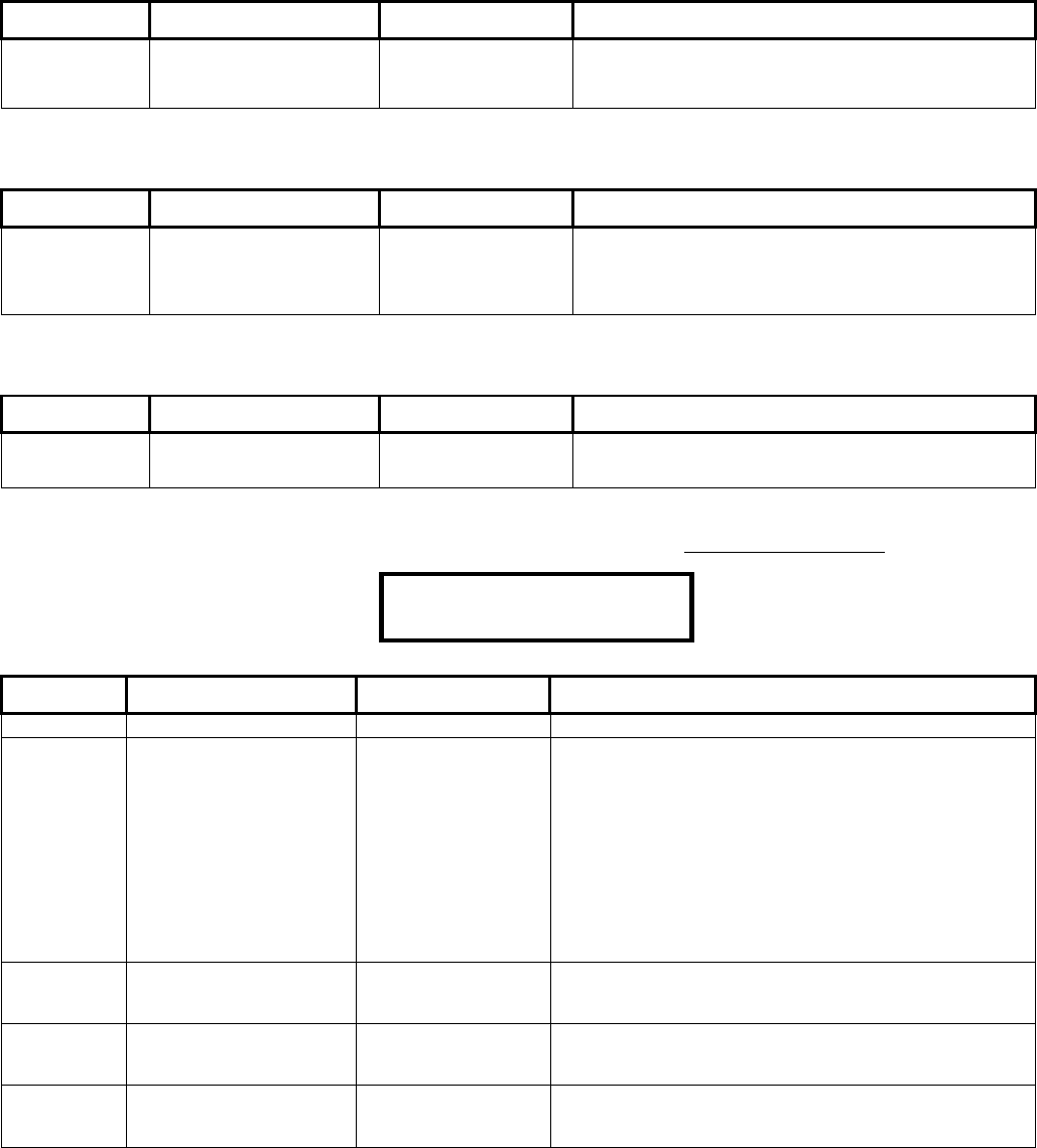
21-3602E rev1.5 Monitor xL™ Advanced Installation Guide 27
M0xx02 Annunciation Map
Keypad Selections (left to right on keypad screen)
Note: “xx” represents the module number.
Default Name Selections Description
Area 1 – 16:
(yes)
Area 1 to Area 16 (yes) □(no) AnnuAreaMap defines which areas the module
can alert sirens, sonalerts and other sound
notifications from.
M0xx03 Arm/Disarm Map
Keypad Selections (left to right on keypad screen)
Note: “xx” represents the module number.
Default Name Selections Description
Area 1 – 16:
(yes)
Area 1 to Area 16 (yes) □(no) Defines which areas can be armed /disarmed from
this e.g. keypad.
Required for Area Group Mode assignments
S00108
M0xx04 Exit Delay Map
Keypad Selections (left to right on keypad screen)
Note: “xx” represents the module number.
Default Name Selections Description
Area 1 – 16:
(yes)
Area 1 to Area 16 (yes) □(no) Defines which areas also have an exit delay when
the area this keypad is assigned to is armed
M0xx05 Keypad Selections Note: “xx” represents the module number.
WARNING: These Access Control features are only available with the addition of the “Feature Expansion Board”.
(left to right on keypad screen) Example:
Pressing the keypad button under ? will display the type of module and the module’s point and output ranges.
Default Name Selections Description
000 Schedule 0-250
01 Single Badge In-
Schedule Mode
0=None, 1=Auto
logon, 2=Auto arm
ON, 3=Auto Arm
STAY, 4=Auto
Disarm STAY,
5=Auto Disarm OFF,
6=Toggle OFF-STAY,
7=Toggle OFF-ON,
8=Toggle STAY-ON,
9=Extend Exit Delay,
10=Auto Work Late.
(UK ACPO=05)
01 Single Badge Out of
Schedule Mode
Same selections as
“Single Badge In
Schedule Mode”.
(UK ACPO=05)
07 Hold Badge In
Schedule Mode
Same selections as
“Single Badge In
Schedule Mode”.
(UK ACPO=02)
07 Hold Badge Out of
Schedule Mode
Same selections as
“Single Badge In
Schedule Mode”.
(UK ACPO=02)
000
·
0
1
·
0
1·
0
7·
0
7·
Save ? M00105

28 Monitor xL™ Advanced Installation Guide 21-3602E rev1.5
M0xx06 Keypad Selections Note: “xx” represents the module number.
WARNING: These Access Control features are only available with the addition of the “Feature Expansion Board”.
(left to right on keypad screen)
Default Name Selections Description
01 Door Number Whether it is the first door or second door on the door
module.
03 Hold time (or Multi-
Badge time)
00-07 Length of time (Delay Table) to present a card to invoke
Hold Badge features (see M0xx:05 above)
If module is Keypad with internal reader, this number is
used by the Delay Table.
If module is Keypad with external reader, this number is
used to time the double or triple card swipes:
00=0.0 sec 04=2.0 sec
01=.75 sec 05=2.5 sec
02=1.0 sec 06=3.0 sec
03=1.5 sec 07=5.0 sec
(no) In or Out Reader (yes) □(no) Assigned to:
A reader mounted outside an area door to track users that
have entered an area.
A reader mounted on the inside of the door to track users
that have left the area.
(no) In or Out Station (yes) □(no) A reader that tracks a user’s location e.g. used like a time
clock.
(no) Badge Access Control (yes) □(no)
(no) Hold PIN Prompt (yes) □(no) Personal access device (card, fob) must be held at e.g.
keypad reader for a response.
(no) Disable Single on
Badge-Hold
(yes) □(no) This determines whether or not the action defined
under 'single' (in or out of schedule) will also occur on
a badge-hold action.
Not selected: Badge-hold produces action defined
under 'single' is included.
Selected: Badge-hold action occurs by itself.
(no) Disarm Card + PIN (yes) □(no) Must also use PIN to turn protection off after using
access device (card, fob) at keypad with internal
reader.

21-3602E rev1.5 Monitor xL™ Advanced Installation Guide 29
M0xx07 Keypad Selections Note: “xx” represents the module number.
WARNING: These Access Control features are only available with the addition of the “Feature Expansion Board”.
(left to right on keypad screen) Example:
Pressing the keypad button under ? will display the type of module and the module’s input and output ranges.
Default Name Selections Description
(no) Reader Defined (yes) □(no)
000 Card Lockout Schedule 00 = No scheduled
lockout
01 – 250 Schedule
A schedule to specify when card access will be blocked
0 Enable or Disable
Cards of Type
0 = None
1=Escort Req’d
2 =non-permanent
users. 3 =all users
0 Enable or Disable
Mode
If enabling reader,
see Note *1 .
If disabling reader,
see Note *2 .
Note *1: If enabling reader, 0=enable for 4 hrs, 1=enable for
8hrs, 2=enable for 12 hrs, 3=enable for 24 hrs, 4=enable for
1 week, 5=enable until midnight tonight, 6=enable
permanently, 7=enable until out of schedule according to
schedule 50.
Note *2: If disabling reader, 0=disable card permanently,
1=disable card but set it so that it can be re-enabled later at
an enabling station, 2= disable card permanently and trigger
auxiliary output , 3= disable card enable re-enroll and trigger
auxiliary output, 4 to 7 = not used, same as 1 (room for
future expansion)
(no) Arming Station or
Keypad Reader
connected to Reader
LCD Keypad
(yes) □(no) NOTE: Bi-colour LED must be enabled for command station
R0017.
(no) Lockout In Schedule (yes) □(no) Toggles the lockout between inside of the chosen schedule (
), compared to outside of the schedule ( □ ).
(no) Enabling Reader (yes) □(no)
·
0
00·
0
·
0
· ···
Save ? M00107
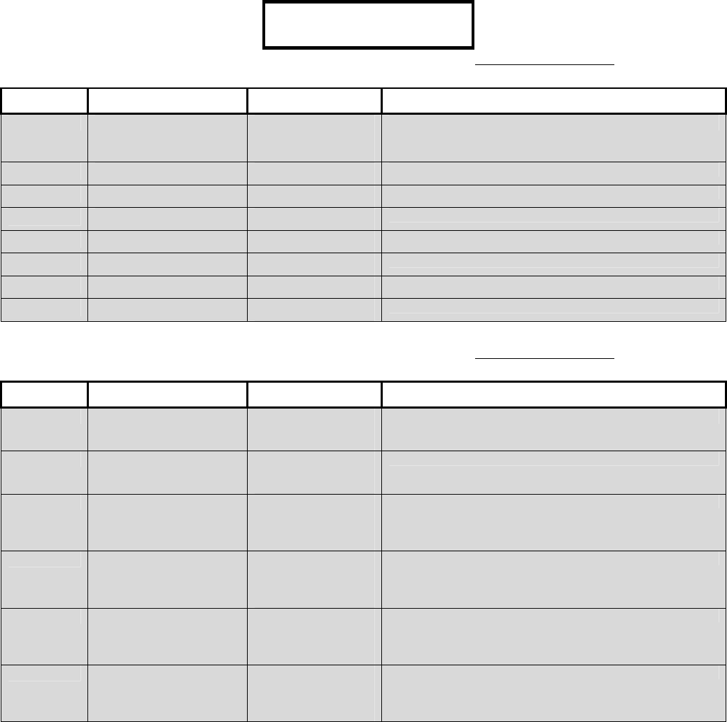
30 Monitor xL™ Advanced Installation Guide 21-3602E rev1.5
M0xx08 Keypad Selections Note: “xx” represents the module number.
(left to right on keypad screen) Example:
WARNING: These Access Control features are only available with the addition of the “Feature Expansion Board”.
(left to right on keypad screen)
Default Name Selections Description
000 Class Map Schedule 00 = Treat as In
Schedule
01 – 250 Schedule
(no) In Schedule A (yes) □(no)
(no) In Schedule B (yes) □(no)
(no) In Schedule C (yes) □(no)
(no) Out of Schedule A (yes) □(no)
(no) Out of Schedule B (yes) □(no)
(no) Out of Schedule C (yes) □(no)
(no) Enable Class Checking (yes) □(no)
M0xx09 Keypad Selections Note: “xx” represents the module number.
WARNING: These Access Control features are only available with the addition of the “Feature Expansion Board”.
(left to right on keypad screen)
Default Name Selections Description
000 Card Mode Schedule 00 = Treat as In
Schedule setting
01 – 250 (Schedule)
000 Reader Mode Schedule 00 = Treat as In
Schedule setting
01 – 250 (Schedule)
0 Card Mode In Schedule 0=Card only
1= Card + PIN
2= Card or UID/ PIN
3= UID/ PIN only
0 Card Mode Out of
Schedule
0=Card only
1= Card + PIN
2= Card or UID/ PIN
3= UID/ PIN only
0 Reader Mode In
Schedule
0=Normal
1= Dual Custody
2= Escort
3= Future
0 Reader Mode Out of
Schedule
0=Normal
1= Dual Custody
2= Escort
3= Future
000······
Save ? M00108
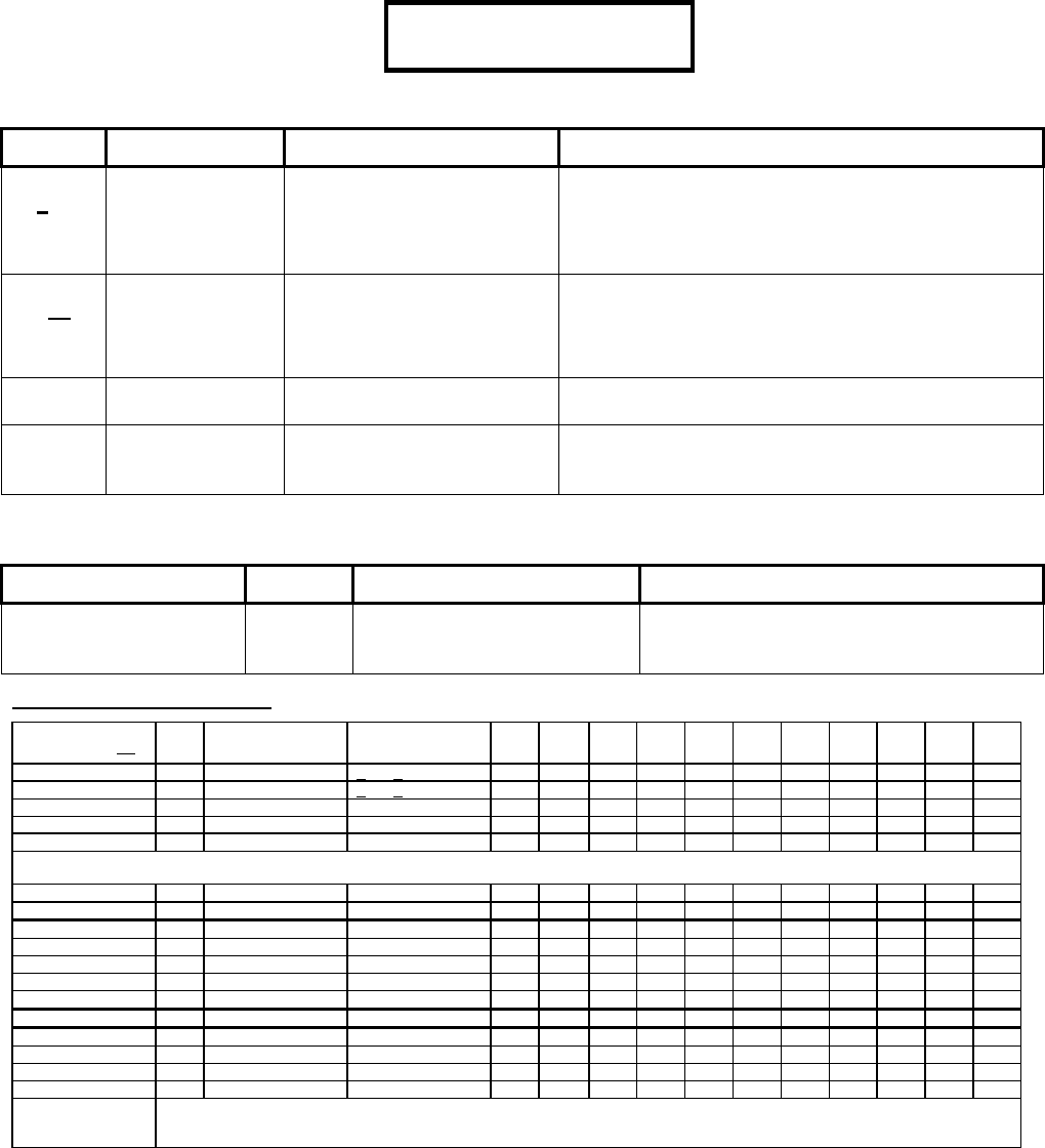
21-3602E rev1.5 Monitor xL™ Advanced Installation Guide 31
Program Section: P001 (Inputs)
Pxx100 Keypad Selections Note: “xx1” represents the input number.
(left to right on keypad screen) Example:
Pressing the keypad button under ? will display the module the point is associated with and the module’s point
range.
Default Name Selections Description
Example:
201
Circuit Type 0: N/C (no EOL)
1: N/C with 2.2k EOL
2: Form “C” single resistor
EOL & N/O with 2.2k EOL
3: Form C—dual 2.2k
First digit of the input’s first 3 digit code for standard types
only. Refer to S007:00 for Custom Circuit Types.
A “000” 3 digit code is an undefined input.
Example:
201
Point Type 01 - 33: See the Input Point
Type Reference table.
80 - 99: Custom types
programmed in section: T080 -
T099.
Second 2 digits of the input’s first, 3 digit code
A “000” 3 digit code is an undefined input.
01 Area this input is
assigned to.
– –
01 Buffer Area – A secondary area that shares Entry/Exit doors with
the above first area. If not a Buffer Area, enter the
same area number as above, again here.
Pxx11 Keypad Selections (left to right on keypad screen)
Note: “xx1” represents the input number.
Default Name Selections Description
Example:
“ FRONT DOOR “
(16 available characters)
Input # 1
Label
– The input name that will appear in input
Status, Alarm menus, etc. Edit the same
as the Greeting Message, S001:04
Input Point-Type Reference
Point Type (###) Class Monitored for these
Area Arming Level(s)
Monitoring Style By-
pass Chime Tx Off Tx
Stay Tx On Sonlrt
Off
Sonlrt
Stay
Sonlrt
On
Siren
Off
Siren
Stay
Siren
On
01 (Entry Door) Burg Stay & On Entry/Exit Door
–
–
–
–
02 (Entry Route) Burg ON Only Entry/Exit Route
–
–
–
–
–
–
03 (Perimeter) Burg Stay & On Immediate
–
–
–
04 (Interior Motion) Burg ON only Immediate
–
–
–
–
–
–
05 (Motion–FAP) Burg ON only FAP
–
–
–
–
–
–
FAP: (False Alarm Preventor) If a FAP input is not OK longer than 10 seconds, an alarm condition occurs. If a FAP input is triggered and immediately resets, a 20
minute timer begins. If the same device is tripped or a different FAP device trips in the same 20 minutes, an alarm occurs.
06 (Day Warning) Burg 24hr Immediate
–
–
–
–
–
07 (24hr Burglary) Burg 24hr Immediate
–
10 (Fire - A) Fire-A 24hr Immediate
–
–
11 (Fire - Delayed) Fire 24hr 15s delay
–
–
12 (Fire - Immed) Fire 24hr Immediate
–
–
13 (Hold-up) holdup 24hr Immediate
–
–
–
–
–
–
–
–
14 (Aux Alert) Emerg 24hr Immediate
–
–
20 (Supervisory) Spvsr 24hr Immediate
–
–
–
–
30 (Local - 24hr) Burg 24hr Immediate
–
–
–
–
31 (Local-Stay&On) Burg Stay & On Immediate
–
–
–
–
–
32 (Future Use) Burg Future Use Future Use
–
–
–
–
–
–
–
33 (Local - ON only) Burg ON only Immediate
–
–
–
–
–
–
–
80 - 99 (Custom) Custom point types as defined in T080 - T099. Custom point types provide full control over input point characteristics, plus additional
features including arm/disarm keyswitch operation, and setting up garage door sensors, Vault/Safe class input points, plus guard-tour
points, and work-late buttons.
2
0
1
·
0
1
·
0
1
·········
Save ? P00100
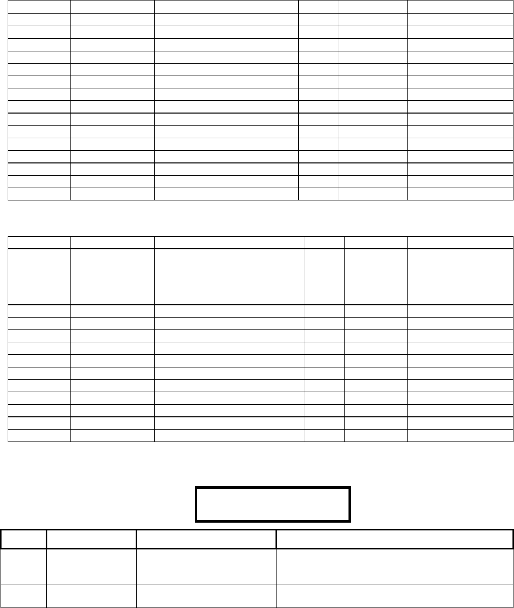
32 Monitor xL™ Advanced Installation Guide 21-3602E rev1.5
Default North American Input Settings (Pxx1:00 and Pxx1:01)
Input Pt. Circuit/Pt. Type Typically Used with
A
rea *Buffer Area Name (Pxxx:01)
P001 201 Entry/Exit Door (w/o access ctrl) 01 01 FRONT DOOR
P002 202 Entry Route - ON Only 01 01 LOBBY MOTION
P003 204 Interior - ON Only 01 01 OFFCE MOTION
P004 204 Interior - ON Only 01 01 INTR MOTION
P005 204 Interior - ON Only 01 01 REAR MOTION
P006 203 Perimeter - Stay & On 01 01 PERIMETER DR
P007 203 Perimeter - Stay & On 01 01 OHD (over head door)
P008 201 Entry/Exit Door (w/o access ctrl) 01 01 REAR DOOR
P009 203 Perimeter - Stay & On 01 01 PERIMETER DR
P010 203 Perimeter - Stay & On 01 01 PERIMETER DR
P011 203 Perimeter - Stay & On 01 01 PERIMETER DR
P012 203 Perimeter - Stay & On 01 01 PERIMETER DR
P013 112 Fire Immediate 01 01 KEYPAD FIRE
P014 013 Hold-up 01 01 KEYPAD PANIC
P015 114 Auxiliary Alert 01 01 KEYPAD EMERG
* A Buffer Area is a secondary area number that the point may also share. Example: a single door that between 2 areas.
Default UK ACPO Input Settings (Pxx1:00 and Pxx1:01)
Input Pt. Circuit/Pt. Type Area Buffer Area
Name (Pxxx:01)
P001 080 Custom # 80
(Command Point,
Class: Supervisory.
See Custom Point Programming and
ACPO)
01 01 LCLCMDATEALL
P002 201 01 01 CCT DESCRIP
P003 202 01 01 CCT DESCRIP
P004 204 01 01 CCT DESCRIP
P005 204 01 01 CCT DESCRIP
P006 204 01 01 CCT DESCRIP
P007 204 01 01 CCT DESCRIP
P008 204 01 01 CCT DESCRIP
P009 204 01 01 CCT DESCRIP
P010 204 01 01 CCT DESCRIP
P011 204 01 01 CCT DESCRIP
P012 206 Day Warning 01 01 SIREN TAMPER
Program Section: E001 (Equipment Trouble Types)
E0xx00 Keypad Selections Note: “xx” represents the equipment trouble type number: 01 – 16.
(left to right on keypad screen) Example:
Default Name Selections Description
## Time Delay. Enter time delay code from
global time delay table.
00 = undefined
System Tamper can not be edited.
Trouble Type
Name
From Equipment Trouble
Type Name Table
01··
S
y
stem Tmpr
Save E00100

21-3602E rev1.5 Monitor xL™ Advanced Installation Guide 33
E0xx01 Keypad Selections (left to right on keypad screen)
Note: “xx” represents the module number.
Default Name Selections Description
Transmit Off (yes) □(no)
Transmit Stay (yes) □(no)
Transmit On (yes) □(no)
Alert Off (yes) □(no)
Alert Stay (yes) □(no)
Alert On (yes) □(no)
Siren Off (yes) □(no)
Siren Stay (yes) □(no)
Siren On (yes) □(no)
Equipment Trouble Type Name Table and Defaults (left to right on keypad screen)
Trouble Type # Name Time Delay Table Transmit, Alert, Siren
O = OFF, S = STAY, O = ON
E001 System Tamper 01 (immediate)
OSO OSO O SO
E002 Low / No Battery 01 (immediate)
E003 AC Mains Failure 23 (4 hours)
E004 No Phone Line
14 (5 min)
(UK ACPO: 00,
disabled)
E005 Report Delay 15 (10 min)
E006 Time Lost 00 (disabled)
E007 Time Change 00 (disabled)
E008 Program Change 00 (disabled)
E009 Program Error 00 (disabled)
E010 Fuse Fail 01 (immediate)
E011 Module (Pod) Trouble 01 (immediate)
E012 Module (Pod) Battery Low 01 (immediate)
E013 Module (Pod) Program Edit 00 (disabled)
E014 Module (Pod) Program Error 00 (disabled)
E015 Output Trouble 00 (disabled)
E016 HSC, Security IP, Trouble 00 (disabled)
(01 immediate)
34 Monitor xL™ Advanced Installation Guide 21-3602E rev1.5
Program Section: B001 (Programmable Outputs)
(left to right on keypad screen) Example:
Pressing the keypad button under ? will
display the location (main panel, module)
of the output and the location’s output range.
Outputs are programmable electronic switches that can be used to signal alarms or control items such as lights,
garage doors, etc. The keypad Programmable Outputs screens allow viewing or changing (to Feature Set 4 only)
the characteristics for each of these outputs.
This system uses a programmable output format referred to as a “Query Condition”. A Query Condition is the
equivalent of the previous output-programming format (bCAPL) with enhancements. It is basically testing if a condition
is valid or not, true or false (e.g. “Is Area 5 On?”). Entering simple output types can be done at an LCD keypad in the
configuration programming output “B” section using output code selections. Advanced, Equation, Logic style outputs
can only be set up using the Director software and sending this output information to the panel using a direct
connection, IP etc.
General Signalling/Switching Functions
Outputs can be set to activate whenever a certain
type of input is triggered or a specific event occurs.
This can be for the entire system, a single area, a
specific door, or for a specific input point.
Door Controller Outputs: These units include dedicated outputs
that are configured along with other reader/door settings (via
R0xx). For details, refer to the "R" (Door) programming section.
Keypad Function Keys
Outputs can be set to respond when a user presses
the “F” function key and a number-key at an 'LCD
keypad'. F1-F5 are available to all users, while F6-F9
and F0 can be set (on an area-by-area basis) to work
only when a user with “Function Key” authority is
logged in.
For details, see the "Function Key PIN Required" selection in
A0xx02.
Function key F5 is pre-set to toggle the keypad chime feature on
and off. It can be programmed for other actions, but is generally
not—since the keypad chime feature would be toggled too.
Suite Security LED Keypads: Function keys on these
units perform a fixed operation (they are not
programmable here).
The Paging Feature
Outputs 001 – 002 should be used for the main
controller’s 2 relay outputs. Outputs 003 – 032
maximum should be considered for assigning to the
main controller for possible STU (subscriber terminal
unit for modem Redcare output connections). Any
outputs 001 – 128 can be set to signal a numeric
pager when triggered by their associated alarm
condition. The specific alarm/event to be associated
with each of the outputs is defined in the System
Program Section S001:06 where the base or
beginning output number is entered and then the
related output numbers are programmed sequentially.
Other settings for the paging feature are set through
screens S005:08 and S005:09. The message sent to
the pager will be the Panel Unique ID: S001:02, and
the associated output number.
Tip: It is very useful to print out a small alarm/output reference
(wallet or pager-size), for each system that has paging set-up.
For details on the "Panel Code" (also known as "Unique ID"),
refer to S001:02.
General Notes:
Programmable output numbers are assigned by the system
when a module that supports outputs is set up. The assigned
numbers will be based on the order the modules are added, and
the number of outputs that are 'reserved' by each module.
Monitor xL Panels---VBUS Outputs and Parallel STU outputs
The Monitor xL panel supports one 8-output modem/STU
(w/configurable base value), plus one 8-ouput VBUS board (with
sequential output numbers starting at a single programmable
base value). A total of 2 VBUS boards are supported if a
Parallel STU is not present. In addition to the settings relating to
VBUS and STU outputs, the "Panel onboard outputs" value must
include the number of STU and VBUS outputs--plus the two on
the panel itself for a grand total. This is selectable as multiples of
4 only (4, 8, 12, etc), so select the next higher value if
necessary. VBUS and STU outputs will NOT be recognized if the
panel onboard outputs value does not account for all of these
outputs.
Location in Software: Configuration ->System (General) ->I/O
Mapping (tab):
Location via Keypad: S001:00, S001:06, and S001:07.
Outputs on a graphic map annunciator module refer to the LEDs
on the front of the module. Outputs 1 and 2 are obtainable as
hard wire connections on the map module’s circuit board.
As an aid when setting up the programmable outputs, it is
extremely useful to create and fill-in a 3-column table to track:
module/connection compared to system input/output reference
#, compared to location/desired operation.
? S
0
0
0
.
0
5 Query
Save ? B00100
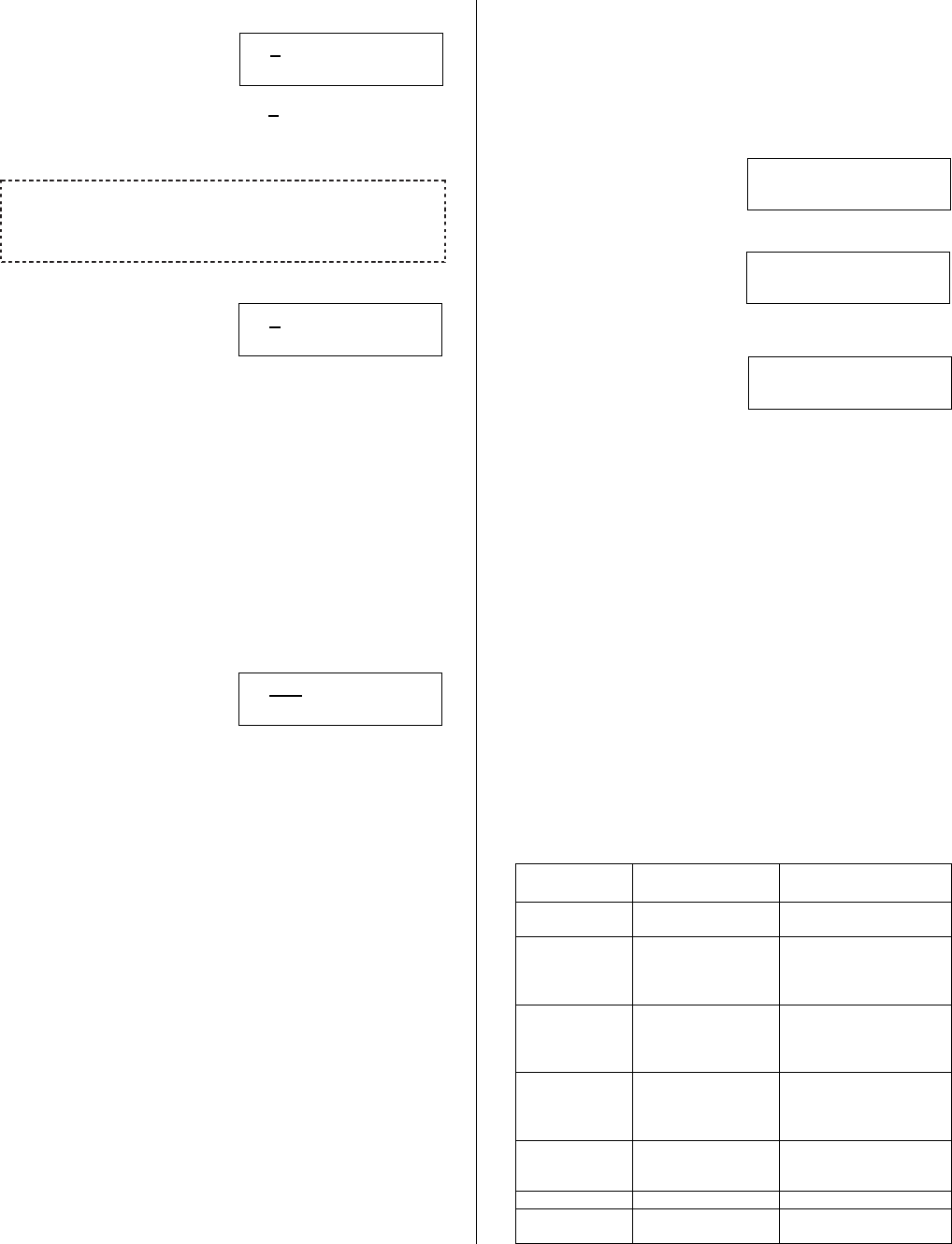
21-3602E rev1.5 Monitor xL™ Advanced Installation Guide 35
Undefined Output LCD Screen
An Undefined Output is
turned off. It can be
changed to any “Query
? 0000.00 Undef
Save ? Bxxx:0
Condition” by changing the first 0 to the letter of any
programming section i.e. “S” for System, “A” for Area
etc. (see page 1 for a full list).
Pressing the keypad button below “ ? “ when the output number
is associated with a module will display the module’s number (i.e.
module # XX), what type it is (e.g. Input/Output module), the
module’s serial number and its output number range.
Query Condition
“q” will represent the first
letter of a programming
section.
? qnnn.cc Query
Save ? Bxxx:0
“nnn” is the number in the programming section
range that the output is assigned to. E.g. 001 – 016
for Areas, 001 – 050 for Schedules. However,
“System” is 000 – 000 because there are no specific
numbers of anything contained in it. ‘000’ would be
entered for “System”.
“cc” is the condition code number for the Query
from the Output Selections tables.
A Query can always be changed from one type to
another and can be set as undefined. E.g. a system
siren (S000.07) can be changed to Area 5 is OFF
(A005:14).
Output type
In the next keypad screen
after pressing Save, any
basic output assignment
T itt
T
imer
Save ? Bxxx:1
can be timed or just follow what the output is
supposed to do.
“i” represents entering a “0” for the output to be a
non-inverted output (e.g. output turns positive) or “1”
for an inverted output (e.g. output turns negative).
“tt” mainly assigns a time delay to the output
from the Timer Delay Codes Table, page 37. If
“00” is entered here it follows a “normal” output
action e.g. “When the system is in alarm”. The
timer delay table begins with entering from 01
being a 1 second timer to 31 being a 1-week
timer. Special entries here are “98” which will
make the output a toggle type. Meaning e.g.
associated keypad command keys when
pressed will turn the output on and the same key
sequence pressed again will turn it off. Entering
“99” is an additional way to turn the output off so
it will never activate.
These previous screens are the only ones that will
permit programming simple outputs using the
following Output Selections tables. The next
output programming screens will only appear
when an advanced output has been programmed
using the Director Software and sent to the panel
with a communications method e.g. direct
connection, IP module. After an advanced
equation output has been sent to the panel,
viewing the related output in the “B” output’s
programming section on an LCD keypad will
display additional screens for it like the following:
A Logic equation output
where “ff” is a following
condition code.
L ff Logic
Save ? Bxxx:2
A logic equation that is
very complicated and can
only be viewed in the
Complex-Director
Save ? Bxxx:0
Director software program.
An output in the outputs
section has been e.g.
improperly programmed.
Error! Bxxx,eee
Save Bxxx:2
This condition will only display in the output’s “B”
programming section on an LCD keypad and not
in Status.
Warning: Ordinarily, this type of error will
display as a result of a complicated equation
output done in the Director software and sent to
the panel. This will make it necessary to correct
the error in the Director software and re-send
the information to the panel.
“xxx” is the output number, 001 – 128, where
the error first occurred. It may not be the same
as the output you are currently viewing. All
outputs after the one affected will display “Error”
and not display any of their settings on the LCD
screen. Outputs after the one in fault will also
cease to operate. All outputs before the one
affected will display their settings and operate
normally.
“eee” will tell you the type of error. Refer to the
following error list.
Error
Code
Description Possible
Solution
000 Not
applicable.
Notify dealer if
persistent.
001 Program
section
unknown.
Check program
section letter i.e.
“A” for Area, “M”
for module etc.
002 Logic equation
condition is
unknown.
Panel firmware
version may be
incompatible with
Director ver.
003 Program
section range
number
invalid.
Check the range #
e.g. Input # 001 –
128.
004 Incompatible
Feature Set #
Panel’s Feature
Set needs
upgrading.
005 - 019 Future use.
020 - 029 Critical Error Notify dealer if
persistent.
36 Monitor xL™ Advanced Installation Guide 21-3602E rev1.5
Output Examples
Examples 1 to 5 are configurable in LCD keypad output programming. Examples 6 to 9 must be configured with the
Director software and Sent to Panel.
Example 1: Simple Single Equation with Follow Output
Bxxx:0 “? D025.00 Query ” - Schedule 25 is in schedule
Bxxx:1 “T 000 Timer ” - Follow (Normal)
Output Bxxx will be ON whenever schedule #25 is in effect.
Example 2: Simple Single Equation with Inverting Output
Bxxx:0 “? D025.00 Query ” - Schedule 25 is in schedule
Bxxx:1 “T 100 Timer ” - Inverting Follow Output
Output Bxxx will be OFF whenever schedule #25 is in effect. Whenever schedule #25 is not in effect, output xxx will
be ON.
Example 3: Simple Single Equation with Timed Output
Bxxx:0 “? D025.00 Query ” - Schedule 25 is in schedule
Bxxx:1 “T 010 Timer ” - Timed positive output, 60 seconds
Output Bxxx will turn on for 60 seconds when schedule 25 first goes into effect.
E.g. schedule 25 is defined as 9am to 5pm, Monday to Friday. Output xxx will turn on for 60 seconds at 9am on
Monday and then will turn off etc. for the rest of the days of the week assigned.
Example 4: Simple Single Equation with Inverting Timed Output
Bxxx:0 “? D025.00 Query ” - Schedule 25 is in schedule
Bxxx:1 “T 110 Timer ” - Timed negative output, 60 seconds
Output Bxxx will turn off for 60 seconds when schedule 25 first goes into effect and will be on otherwise.
E.g. schedule 25 is defined as 9am to 5pm, Monday to Friday. Output xxx will normally be ON and will turn off for
60 seconds at 9am on Monday and then will turn back on etc. for the rest of the days of the week assigned.
Example 5: Toggle Output on function Key
Bxxx:0 “? A001.01 Query ” - Function Key 1 in area 1
Bxxx:1 “T 098 Timer ” - Toggle output.
The key term is Timer “Toggle Output” (T098).
Note that T198 could be entered but this has the same function as T098.
Pressing Function key 1 in area 1 turns the output ON. Repeating this procedure turns it off.
Example 6: Simple Two Term AND Equation with Normal Output
Configurable only with Director software and Sent to Panel
Bxxx:0 “? D025.00 Query ” - Schedule 25 is in schedule
Bxxx:1 “? A002.14 Query ” - Area 2 is OFF
Bxxx:2 “L 01 Logic ” - Logical AND operator – additional screen generated with Director software.
Bxxx:3 “T 000 Timer ” - Follow (Normal) – additional screen generated with Director software.
Output Bxxx will turn on when schedule 25 is in effect AND area 2 is off. Otherwise, output xxx will be off.
*** This equation can not be created directly at the LCD Keypad – it would have to be created in the Director
software. After the logical operation and timer value conditions have been made in the Director software and sent to
the panel, modifying them can be done at the keypad but not any other changes.
*** This equation can not be deleted from the LCD keypad directly. Values for the first term (Bxxx:0) can not be
undefined. This type of editing can only be done using the Director software.
21-3602E rev1.5 Monitor xL™ Advanced Installation Guide 37
Example 7: Simple Two Term OR Equation with Timed Output
Configurable only with Director software and Sent to Panel
Bxxx:0 “? A001.15 Query ” - Area 1 is not ON
Bxxx:1 “? A002.14 Query ” - Area 2 is OFF
Bxxx:2 “L 00 Logic ” - Logical OR operator – additional screen generated with Director software.
Bxxx:3 “T 012 Timer ” - Timed output, 2 minutes – additional screen generated with Director software.
1. Output Bxxx will turn on for 2 minutes when area 1 changes from on or when area 2 goes off from some other
state.
2. The output will not turn back on again after the 2 minutes expire until area 1 goes On and Area 2 is either STAY or
ON.
3. After these two conditions are met, the output will turn back on as noted in point 1.
Example 8: Flash a LED when a Condition is True
Configurable only with Director software and Sent to Panel using “System – Special Outputs”
Bxxx:0 “? A016.24 Query ” - A point is bypassed in Area 16
Bxxx:1 “? S001.00 Query ” - Turns 1 sec On, 1 sec Off
Bxxx:2 “L 01 Logic ” - Logical AND operator
Bxxx:3 “T 000 Timer ” - Follow (Normal)
When a point is bypassed in area 16, the output will flash 1 second on, 1 second off.
This is achieved by the logical AND of the area condition query and the special On /Off effect available in System –
Special Outputs programming.
Example 9: (Complicated) Flash a LED for 45 Minutes after a Panic Token is Detected in an
Area
Configurable only with Director software and Sent to Panel using “System – Special Outputs”
B001:0 “? A001.47 Query ” - Panic Token used in Area 1
B001:1 “T 019 Timer ” - Timed Output, 45 minutes
B002:0 “? S001.00 Query ” - Turns 1 sec On, 1 sec Off
B002:1 “? B001.00 Query ” - Output 1 is ON
B002:3 “L 01 Logic ” - Logical AND operator
B002:4 “T 000 Timer ” - Follow (Normal)
2 separate outputs are used to perform this procedure.
A 45 minute timer is applied to panic tokens detected in area 1 in e.g. output # “B001”.
The output state of B001 (timed output based on panic token in area 1) is used to logically “AND” additional output #
e.g. B002 with the Special System 1 second On/Off selection. The important detail is that we use Follow (Normal)
for output B002, in order for the timer not to re-trigger.

38 Monitor xL™ Advanced Installation Guide 21-3602E rev1.5
Default System Programmable Outputs
North America
Output # / Location Default Codes / Setting Meaning / Operation
B001:0 (motherboard)
B001:1
“? S000.07 Query ”
“T 000 Timer ”
- Follows Alarm Siren
- Follow (Normal)
B002:0 (motherboard)
B002:1
“? S000.05 Query ”
“T 000 Timer ”
- When system is IN ALARM.
- Follow (Normal)
B003:0 (keypad)
B003:1
“? A001.01 Query ”
“T 005 Timer ”
- Function Key 1 on Area 1 1st keypad.
- Positive trigger, 10 sec delay.
B004 - B128
“? 0000.00 Undef ”
“T 000 Timer ”
- Undefined output
- Follow (Normal)
UK
Output # / Location Default Codes / Setting Meaning / Operation
B001:0 (motherboard)
B001:1
“? S000.66 Query ”
“T 100 Timer ”
- ACPO Siren
B002:0 (motherboard)
B002:1
“? S000.67 Query ”
“T 100 Timer ”
- Confirmed Alarm (ACPO strobe)
B003:0 (keypad)
B003:1
“? A001.33 Query ”
“T 000 Timer ”
- When area Entry / Exit delay is in progress – provides a steady
output (STAY & ON).
B004:0 (WW STU)
“? S000.60 Query ”
“T 100 Timer ”
- Personal ACPO Attack
B005:0 (WW STU) “? S000.61 Query ”
“T 100 Timer ”
ACPO Unconfirmed Alarm
B006:0 (WW STU) “? S000.62 Query ”
“T 100 Timer ”
ACPO Area Set / Unset
B007:0 (WW STU) “? S000.64 Query ”
“T 100 Timer ”
Bypass in Effect
B008:0 (WW STU) “? S000.54 Query ”
“T 100 Timer ”
Local AC (mains) failure.
B009:0 (WW STU) “? S000.65 Query ”
“T 100 Timer ”
ACPO Confirmed Alarm
B010:0 (WW STU) “? A001.32 Query ”
“T 100 Timer ”
Area is in ‘Walk’ or ‘Hold-up’ test.
Timer Delay Codes (Bxxx:1)
00: output
default;
01: 1 sec;
02: 2 sec;
03: 3 sec;
04: 5 sec;
05: 10 sec;
06: 15 sec;
07: 20 sec;
08: 30 sec;
09: 45 sec;
10: 60 sec;
11: 90 sec;
12: 2 min;
13: 3 min;
14: 5 min;
15: 10 min;
16: 15 min;
17: 20 min;
18: 30 min;
19: 45 min;
20: 60 min;
21: 90 min;
22: 2 hr;
23: 4 hr;
24: 6 hr;
25: 8 hr;
26: 10 hr;
27: 12 hr;
28: 16 hr;
29: 20 hr;
30: 1 day;
31: 1 week
Specialty
Entries:
98 = toggle
99 = output off
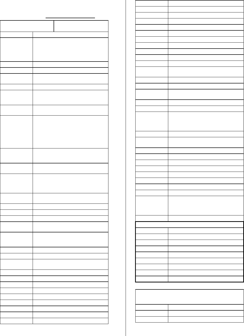
21-3602E rev1.5 Monitor xL™ Advanced Installation Guide 39
Output Selections Table
WARNING: Access Control related outputs can only be used
with the addition of the “Feature Expansion Board”.
Program Section (“q”)
“S”ystem
Section Range (“nnn”)
000 – 000
Code “cc” Description
00 Fallback sonalert (at control panel) if
Module Bus fails. Provides 1 sec. Output
every 8 sec. And activates if there is no
operational keypad in an area with
programmed keypads.
01 Not Used
02 When system is FULLY ON
03 PARTIALLY ON. One or more areas
ON.
04 When system is FULLY OFF
05 When system is IN ALARM - resets
when point(s) restore
(includes pseudos & tampers)
06 Follows ALARM (BURG / EMERG) &
FIRE siren steady.
07 Follows ALARM siren - steady for BURG
/ EMERG. Keypad tone & siren is 1 sec
on/off for FIRE.
For UL: When using this output type,
fire siren is ½ sec on/off three times, 1.5
sec pause, and repeats. Keypad tone is
1 sec on/off.
08 Follows ALARM siren - steady for BURG
/ EMERG and provides 2 sec on/off for
FIRE
09 Digital PHONE LINE trouble (follows
report delay or line failure)
10 System WAS IN ALARM. This is only for
input points in alarm e.g. NOT for
system trouble (clears when alarmed
areas are turned off then back on again)
11 When there is a point BYPASSED
somewhere in the system
12 When any ‘FIRE’ point is in alarm
13 When any ‘HOLD UP’ point is in alarm
14 When any ‘Aux Alert' point is in alarm
15 When any ‘VAULT / SAFE’ type point is
in alarm
16 When any ‘'Burglary' point is in alarm.
Delayed burglary for European
Version.
17 When any ‘Supervisory' point is in alarm.
18 When any 'Pseudo' is in alarm
19 Pseudo 1 – System Trouble / All type
tamper for European Version.
20 Pseudo 2 – Battery Trouble
21 Pseudo 3 – AC (Mains) Trouble
22 Pseudo 4 – Phone Trouble
23 Pseudo 5 – Report Delay
24 Pseudo 6 – Time Lost
25 Pseudo 7 – Time Change
26 Pseudo 8 – Program Change
27 Pseudo 9 – Program Error
28 Pseudo 10 – Fuse Failure
29 Pseudo 11 – Module Trouble
30 Pseudo 12 – Module Battery Low
31 Pseudo 13 – Module Program Edit
32 Pseudo 14 – Module Program Error
33 Pseudo 15 – Misc. Trouble
34 Pseudo 16 – SIP Trouble
35 Duress Pin
36 Doors Unlocked.
37 Doors Locked Out
38 Doors Held Open
39 Doors Forced
40 Doors Tamper (door contact condition:
no EOL resistor etc.)
41 Doors Open
42 Doors Secure
43 Doors Sensor Trouble (magnetic bond
sensor not ok)
44 Global Invalid PIN and / orCard lockout.
45 Host (Director) computer is On-Line.
46 Host (Director ) computer is Off-Line.
Response time for IP, external modem,
direct connection is 2 min. Bell 103 is 1
min.
47 SIP On-Line.
48 SIP Off-Line. Response time is 3
minutes.
49 Any point in tamper.
50 Any point in Alarm.
51 Any area is Force Arming
52 Any area Failed to Close
53 Phone Line Failure
54 Local AC (mains) failure.
55 System Tamper – European Version.
56 System Fault – European Version.
57 System WAS IN ALARM. This is only for
input points in alarm e.g. NOT for
system trouble (clears when alarmed
areas are turned off)
58 Bypass is in effect in any armed area.
European Version (System)
59 Fire
60 Personal Attack
61 Unconfirmed Alarm
62 Area Set / Unset
63 Freezer / Fire Fault
64 Bypass in Effect
65 Confirmed Alarm
66 Siren
67 Confirmed Alarm (Strobe)
System Special Outputs. Section Range: 001 – 001. See
examples 8 & 9 in Output Examples. NOTE: Only
configurable through the Director Software.
00 1 sec on, 1 sec off
01 2 seconds on every minute
02 10 seconds on every minute

40 Monitor xL™ Advanced Installation Guide 21-3602E rev1.5
Program Section (“q”)
“D” Schedule
Section Range (“nnn”)
Enter 001 – 050
Code “cc” Description
00 Schedule in Schedule
01 15 minutes prior to In Schedule
(opening)
02 15 minutes prior to Out of Schedule
(closing)
03 Holiday in Effect (Whether Type 1,2,3 or
No Access)
04 No Access, Holiday in effect.
Program Section (“q”)
“H”oliday
Section Range (“nnn”)
Enter 001 – 032
Code “cc” Description
00 Holiday in Effect (Whether type 1,2, 3 or
No Access)
Program Section (“q”)
“A”rea
Section Range (“nnn”)
Enter 001 – 016
Code “cc” Description
00 Function Key 0
01 Function Key 1
02 Function Key 2
03 Function Key 3
04 Function Key 4
05 Function Key 5
06 Function Key 6
07 Function Key 7
08 Function Key 8
09 Function Key 9
10 When area is ON
11 When Area WAS IN ALARM. This is
only for input points in alarm e.g. NOT
for system trouble (clears when alarmed
areas are turned off)
12 When area is in STAY 1
13 When area is in STAY 1 or (2 future)
14 When area is OFF
15 When area is Not ON
16 When area is Not OFF
17 When area is in ALARM. Resets when
point(s) restore or follows siren timeout
(includes pseudo's & tampers)
18 When area WAS IN ALARM. This is only
for input points in alarm e.g. NOT for
system trouble (clears when alarmed
areas are turned off then back on again)
19 Follows ALARM siren - steady for BURG
/ EMERG and provides 1 sec ON/OFF
for FIRE
20 Follows ALARM siren - steady for BURG
/ EMERG and provides 2 sec ON/OFF
for FIRE
21 Follows sonalert, chime & provides
Entry/Exit tones when armed to STAY &
ON (UK ACPO = Fail to Arm)
22 Follows sonalert, chime & does not
provide Entry/Exit tones when armed to
STAY but provides Entry/Exit tones in
ON (UK ACPO = Fail to Arm)
23 Follows Garage Entry Tones
24 When any point in this area is
BYPASSED
25 When any ‘FIRE’ type point in this area
is in alarm
26 When any ‘HOLD UP’ type point in this
area is in alarm
27 When any ‘AUXILIARY ALERT’ type
point in this area is in alarm.
28 When any ‘VAULT / SAFE’ type point is
in alarm.
29 When any ‘BURGLARY’ type point in
this area is in alarm.
30 When any ‘Supervisory' point is in alarm.
31 When any 'Pseudo' is in alarm.
32 Area is in ‘Walk’ or ‘Hold-up’ test.
33 When area Entry / Exit delay is in
progress – provides a steady output
(STAY & ON).
34 When area Entry delay is in progress -
provides a steady output (STAY & ON).
35 When area Exit delay is in progress -
provides a steady output (STAY & ON).
36 When the area is ‘Ready To Arm’ - i.e.
all points are secure.
37 When the area’s active schedule is in
effect.
38 When the area schedule is CLOSING in
15 minutes.
39 Doors Unlocked.
40 Doors Locked Out.
41 Doors Held Open.
42 Doors Forced.
43 Door Tampers (door contact condition:
no EOL resistor etc.)
44 Doors Open.
45 Doors Secure.
46 Door Sensor Troubles (magnetic bond
sensor not ok)
47 Panic Token Detected.
48 Area “Empty” (User count <= minimum).
49 Area ”Full” (User Count >=Maximum).
50 No Detected Activity in Area.
51 Activity Detected in Area.
52 15 minutes prior to Scheduled “Arm to
ON” Level.
53 15 minutes prior to Scheduled “Arm to
STAY” Level.
54 15 minutes prior to Scheduled “Arm to
OFF” Level.
55 Area schedule is active.
56 Auto-command schedule is active.
57 Failed to close.
58 Any point in tamper in area.
59 Area armed with points bypassed.
60 Area Force Armed.
61 Invalid Card / PIN Lockout present.
62 Wandering Patient detected.
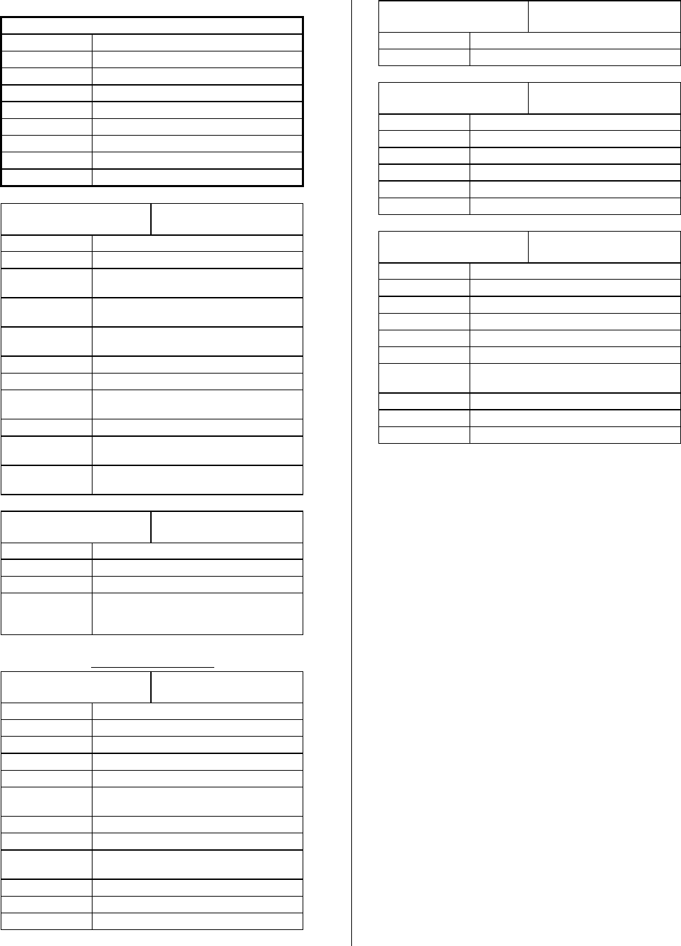
21-3602E rev1.5 Monitor xL™ Advanced Installation Guide 41
European Version (Area)
63 Siren
64 Confirmed Alarm Strobe
65 Fire
66 Personal Attack
67 Unconfirmed Alarm
68 Set / Unset
69 Freezer / Fire Fault
70 Bypass in Effect
71 Confirmed Alarm
Program Section (“q”)
“P”oint (Inputs)
Section Range (“nnn”)
Enter 001 – 128
Code “cc” Description
00 When point is NORMAL.
01 Any time the point is NOT NORMAL
(open, tamper, alarm)
02 When point is NOT NORMAL in OFF or
STAY (open, tamper, alarm)
03 When point is NOT NORMAL in ON
(open, tamper, alarm)
04 When point is in ALARM
05 When point is BYPASSED
06 When the time delay is active (Pre-alarm
Warning).
07 Point is in Tamper.
08 Point is in Delay. Follows a Custom Pt
Type that has a time delay.
09 Positive confirmation of Command Point
activation.
Program Section (“q”)
“B” Output State
Section Range (“nnn”)
Enter 001 – 128
Code “cc” Description
00 An actual output is on.
01 Equation Output is TRUE
02 Manual Command is in effect from the
Director software Outputs Section,
Control & Status.
WARNING: Access Control related outputs can only be used with
the addition of the “Feature Expansion Board”.
Program Section (“q”)
“R” Doors
Section Range (“nnn”)
Enter 001 – 032
Code “cc” Description
00 Door Unlocked
01 Door Locked Out
02 Door Held Open
03 Door Forced
04 Door Tamper (door contact condition: no
EOL resistor etc.)
05 Door Open
06 Door Secure
07 Door Sensor Trouble (magnetic bond
sensor not ok)
08 Door Blocked by Interlock Condition
09 Wandering Patient Detected
10 Door entry Delay in Effect
Program Section (“q”)
“F” loors
Section Range (“nnn”)
Enter 001 – 124
Code “cc” Description
00 Floor Desecure
Program Section (“q”)
“M” odule
Section Range (“nnn”)
Enter 01 – 24
Code “cc” Description
00 On Line
01 Tamper
02 Comms Trouble (Substitution & Comms)
03 Battery Trouble (Module)
04 User logged on to e.g. LCD keypads
Program Section (“q”)
“C” Suite
Section Range (“nnn”)
Enter 01 – 24
Code “cc” Description
00 Alarm
01 Fire
02 Tamper
03 Siren / Sonalert
04 Module Communications Trouble
05 Suite Normal (No Alarm, Fire, Tamper,
Siren / Sonalert, Comms Trouble)
06 Suite in STAY level.
07 Suite in ON level.
08 Suite in STAY or ON level.

42 Monitor xL™ Advanced Installation Guide 21-3602E rev1.5
Program Section: L001 (Authority Levels)
L00100 Keypad Selections
(left to right on keypad screen) Example:
Default Name Selections Description
(yes) First Authority
Level Defined?
(yes) □ (no)
MASTER First Authority
Level Name
Edit the same as the
Greeting Message, S001:04
Alphanumeric name for authority level - 12 characters
(A blank name field means level is undefined.)
L00101 Keypad Selections (left to right on keypad screen)
Default Name Selections Description
001 User Edit Group
000 Floor Group
(yes) Accept Duress
Pin
(yes) □ (no) If “yes” then accept global duress functionality for this
Authority.
L00102 – 17 Keypad Selections (left to right on keypad screen)
Default Name Selections Description
001 Profile Number 0 = none,
1-100 = profile #
From Program Section “I” Authority Level Profiles.
PROFILE MSTR Profile name 12 Characters (if available, not editable)
NOTES:
Profiles created in I00100 are applied to areas L00102 – 17 to permit authority of a user’s abilities in that area.
L00102 for area 1, L00103 for area 2 to L001017 for area 16.
Authority levels applied in areas here will permit authority for Area Group Mode S00108.
·MASTER ··
Save L00100

21-3602E rev1.5 Monitor xL™ Advanced Installation Guide 43
Program Section: Q001 (Floor Maps)
Q00100 Keypad Selections
(left to right on keypad screen) Example:
Default Name Selections Description
000 Schedule 0 = none,
01-250 = schedule #
Q00101 – 08 Floor Map
Keypad Selections (left to right on keypad screen)
Default Name Selections Description
(no)
All Floors
Floor 1 to 16 (yes) □ (no) 1-16 up to 124
Program Section: W001 (User Edit W)
W00100 Keypad Selections
(left to right on keypad screen) Example:
Default Name Selections Description
MASTER User Edit Name 12 characters
W00101,03,05,07,09,11,13,15 Keypad Selections (left to right on keypad screen)
Default Name Selections Description
00001 User Start User Start Range, 0 to end of
users.
00020 User End User End Range, to end of
users.
W00102,04,06,08,10,12,14,16 Keypad Selections (left to right on keypad screen)
Default Name Selections Description
0001 Authority Start Authority Start Range, 0 to
end of authorities.
0030 Authority End Authority End Range, to end
of authorities.
MASTE
R
····
Save W00100
000················
Save Q00100
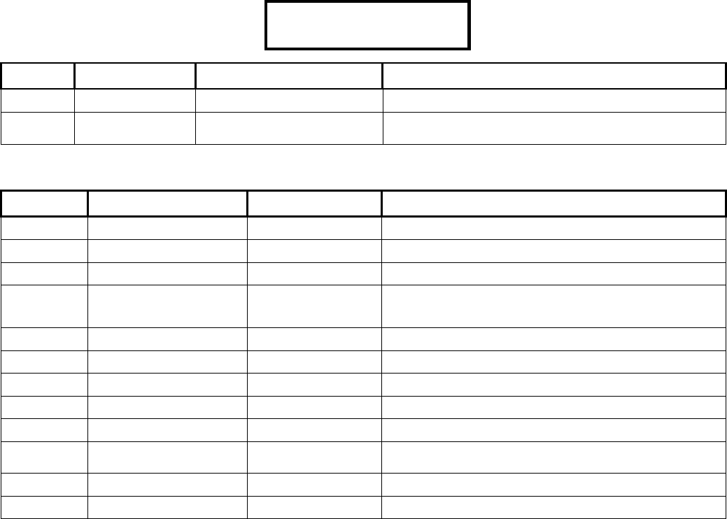
44 Monitor xL™ Advanced Installation Guide 21-3602E rev1.5
Program Section: I001 (Profile I)
I00100 Keypad Selections
(left to right on keypad screen) Example:
Default Name Selections Description
(yes) Profile Defined? (yes) □ (no)
PROFILE
MSTR
Profile Name Edit the same as the
Greeting Message, S001:04
Alphanumeric name for authority level - 12 characters
(A blank name field means level is undefined.)
I00101 Unscheduled Intrusion Related Authority
Keypad Selections (left to right on keypad screen)
Default Name Selections Description
(yes) Emergency Off (yes) □(no)
(yes) Isolate a trouble point (yes) □(no)
(yes) Bypass (yes) □(no)
(yes) Auto-Remove Bypass (yes) □(no) A bypass put on a protection point from the previous armed
period is automatically removed when the user turns the
area to OFF.
(yes) Test (yes) □(no)
(yes) Service Test (yes) □(no)
(yes) Silence Alarm (yes) □(no)
(yes) Status (yes) □(no)
(yes) History (yes) □(no)
(yes) Function-Key
Authorization
(yes) □(no)
(yes) Work Late (yes) □(no)
(yes) Suspend Schedule (yes) □(no)
·PROFILE MSTR··
Save I00100

21-3602E rev1.5 Monitor xL™ Advanced Installation Guide 45
I00102 Unscheduled Access Related Authority
Keypad Selections
(left to right on keypad screen) Example:
Default Name Selections Description
00 Group Number 0 = No Group Authority Group Number
1...62,63 = All Group Authority
0 Group Mode 0 = “is equal to”
1 = “greater than or equal to”
(yes) Access Off (yes) □(no)
(yes) Access Stay (yes) □(no)
(yes) Access On (yes) □(no)
(yes) Escort (yes) □(no)
(no) Visitor (yes) □(no)
(yes) Master Override (yes) □(no)
(no) Wandering patient (yes) □(no)
(yes) Reset door alarm (yes) □(no)
(no) Panic Token (yes) □(no)
I00103 Keypad Selections (left to right on keypad screen)
Default Name Selections Description
000 Schedule A 0=undefined,
1 - 250 schedule #
000 Schedule B 0=undefined,
1 - 250 schedule #
000 Schedule C 0=undefined,
1 - 250 schedule #
I00104 Scheduled Intrusion Related Authority
Keypad Selections (left to right on keypad screen)
NOTE: The necessary Authority Level is required to affect the following area protection changes in and out of
schedule. NOTE: 3 schedules maximum can be mixed and matched.
Default Name Selections Description
1 On 0=None, 1=Always, 2=Schedule A in effect, 3=Schedule A not in effect,
4=Schedule B in effect, 5=Schedule B not in effect, 6=Schedule C in effect,
7=Schedule C not in effect
1 Off
1 Stay
1 Auto
Disarm to
OFF
0= Stay, 1= Off, 2= Schedule A in effect turn Off /not in effect, turn to STAY, 3=
Schedule A in effect, turn to STAY / not in effect, turn Off 4= Schedule B in
effect, turn Off /not in effect, turn to STAY, 5= Schedule B in effect turn to STAY
/not in effect, turn Off, 6= Schedule C in effect, turn Off /not in effect, turn to
STAY, 7= Schedule C in effect turn to STAY /not in effect, turn Off.
1 Auto
Disarm
all Areas
0= single 1= All, 2= Schedule A in effect all areas off /out of schedule, area
entering off, 3= Schedule A in effect, area entering off /not in effect, all areas off.
4= Schedule B in effect all areas off /out of schedule, area entering off, 5=
Schedule B in effect, area entering off /out of schedule, all areas off, 6=
Schedule C in effect all areas off /not in effect area entering off , 7= Schedule C
in effect area entering off /out of schedule, all areas off.
00·0· ··
Save I00102
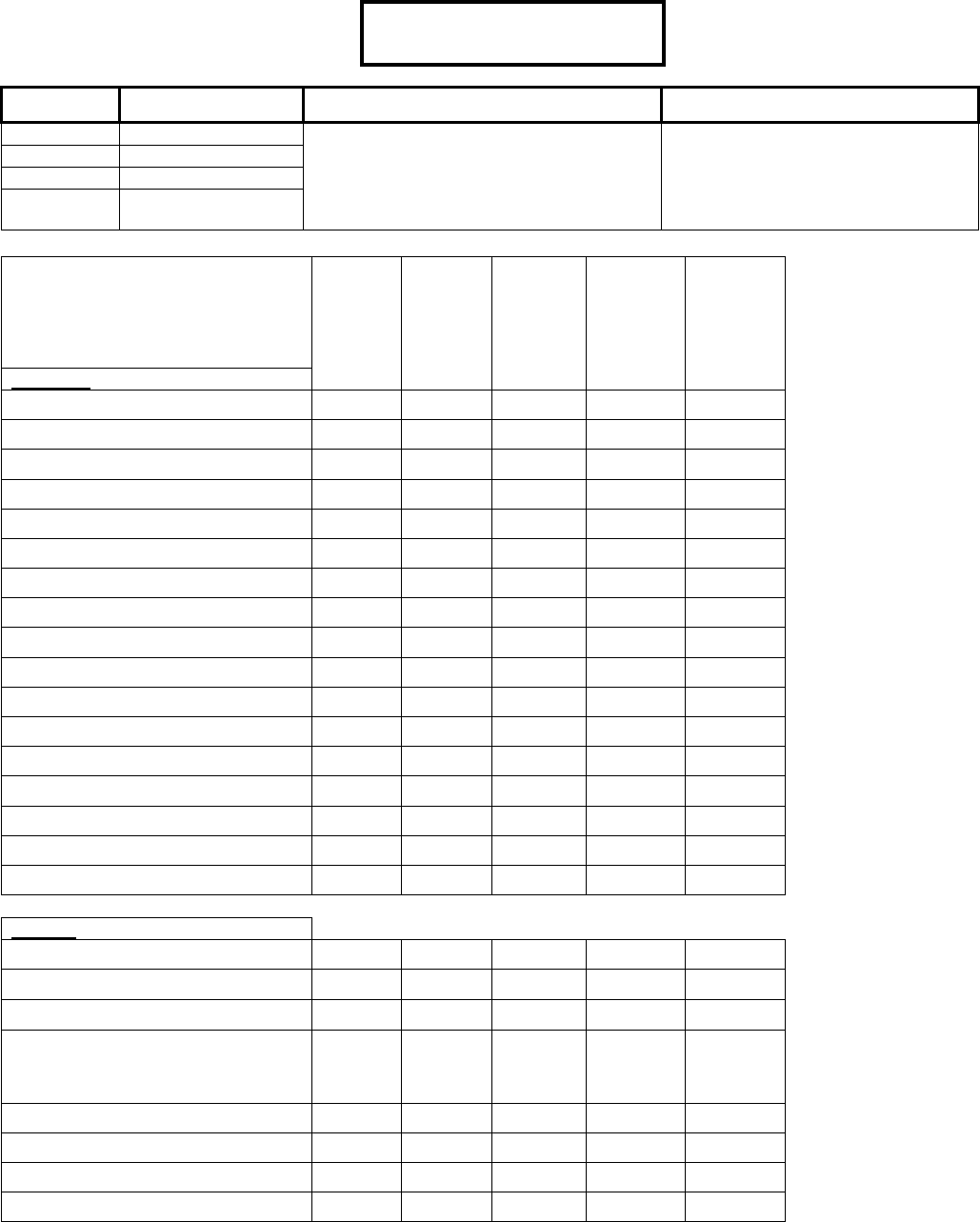
46 Monitor xL™ Advanced Installation Guide 21-3602E rev1.5
I00105 Scheduled Intrusion Related Authority
Keypad Selections
(left to right on keypad screen) Example:
Default Name Selections Description
1 Door Command 0=None, 1=Always, 2=Schedule A in
effect, 3=Schedule A not in effect
4=Schedule B in effect, 5=Schedule B
not in effect 6=Schedule C in effect
7=Schedule C not in effect
1 Class A
1 Class B
1 Class C
Default Authority Settings
Maste
r
I001.00 – 005
Superviso
r
I002.00 – 005
Employee
I003.00 – 005
Worke
r
I004.00 – 005
Cleane
r
I005.00 – 005
Intrusion
Emergency Off
Isolate
Bypass
Auto-lift Bypass
Test
Service Test
Silence Alarm
Status
History
Function Key Authorization
Work Late
Suspend Schedule
On
Off
Stay
Auto Disarm to Off
Auto Disarm all Areas
Access
Access when Area is Off/On/Stay
Escort
Master Override
Reset Door Alarm
At system readers with a user card. Not at
an Arming Station where 9 is used to
silence.
Door Command
Class A
Class B
Class C
1·1·
1
·
1
·············
Save I00105
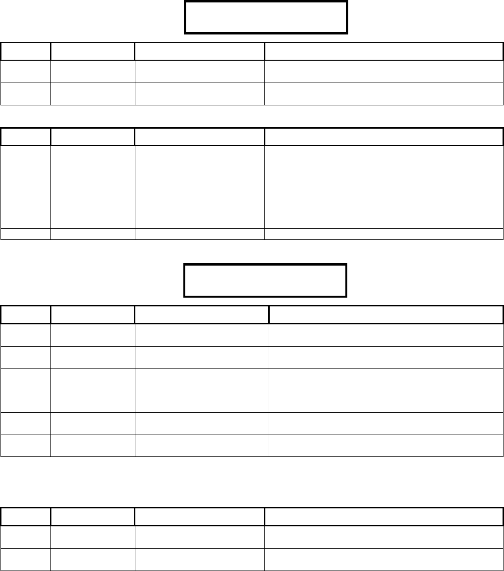
21-3602E rev1.5 Monitor xL™ Advanced Installation Guide 47
Program Section: U001 (Users)
U00100 Keypad Selections
(left to right on keypad screen) Example:
Default Name Selections Description
MASTER
USER
User Name Edit the same as the
Greeting Message, S001:04
Alphanumeric name for authority level - 12 characters
(A blank name field means user is undefined.)
001 Authority Level 00 = undefined user
01…30 = authority level
Assign an existing Authority Level number.
U00101 Keypad Selections (left to right on keypad screen)
Default Name Selections Description
blank Card Number 7 Digits Numeric for Old 24
bit Card Version:
0000000-9999999
9 Digits Numeric for
Expanded 32 bit Card
Version.
0000000000-9999999999
A card numbered 9898 is entered from the right e.g.
0000009898 for both 7 and 9 digit cards.
00 Card Version 0-15
U00102 Keypad Selections
(left to right on keypad screen) Example:
Default Name Selections Description
000 Suite Security
Floor Number
0-124 Not applicable for feature sets less than 5. Greater
then 5 are Director Software/Elevator, display only.
(no) Addition Floor (yes) □ (no) Not applicable for feature sets less than 5. Greater
then 5 are Director Software/Elevator, display only.
0 Suite Security
Authority
0-7
0 Not Assigned by system
1 Undefined on the condo
2-7 Condo Authorities
0 Language 0 = English, 1 = French, 2 =
Dutch, 3 = Spanish
(no) Physically
Challenged
(yes) □ (no)
Note = Condo Floor Number is “000” and Addition Floor is “No” for a Feature Set less than five. Both will indicate active values
through the Director Software if the Feature Set is greater then five and with elevator selections. Both are only for display purposes
in this screen.
U0013 Keypad Selections (left to right on keypad screen)
Default Name Selections Description
_ _ _ _ User’s PIN
number.
– Default MASTER User 001’s ID is 001, PIN 7793 (PSWD)
_ _ _ _ Re-enter User’s
PIN number.
– To avoid incorrect fist entry.
MASTER USER
0
0
1·
Save U00100
000··
0
·
0
··········
Save U00102
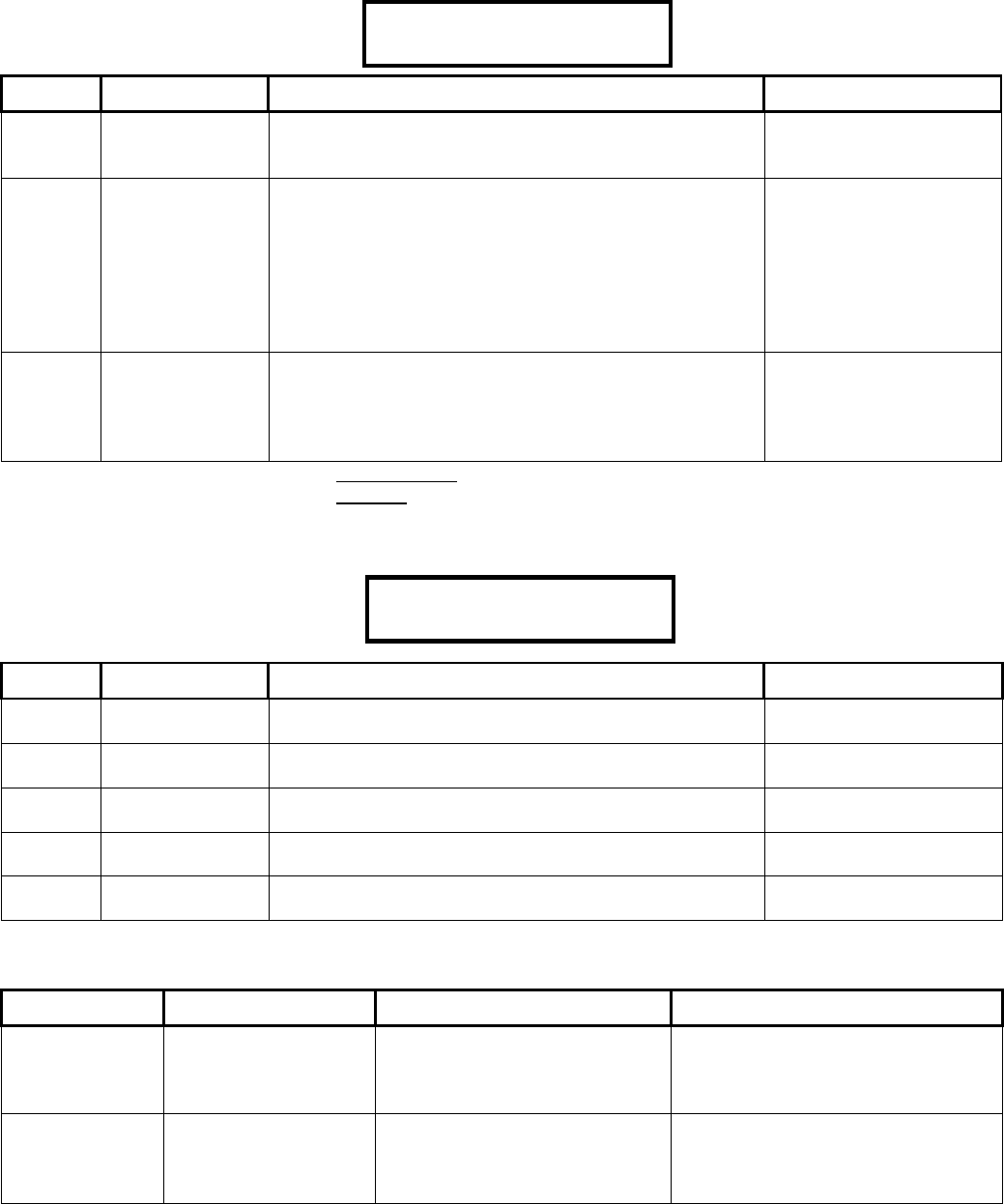
48 Monitor xL™ Advanced Installation Guide 21-3602E rev1.5
Program Section: H001 (Holidays)
H00100 Keypad Selections
(left to right on keypad screen) Example:
Default Name Selections Description
00 Month Up to 2 digits:
01 – 12
13 = Reserved (for future e.g. Easter, Yom Kippur, etc)
00 Day Up to 2 digits:
01 - 31: Day of month
32 - 38: 1st Sun–Sat of month
39 - 45: Last Sun–Sat of month
46 – 52: 2nd Sun–Sat of month
53 – 59: 2nd last Sun–Sat of month
60 – 66: 3rd Sun–Sat of month
67 – 73: 3rd last Sun–Sat of month
0 Type One digit
0: No access holiday
1: Holiday Type One
2: Holiday Type Two
3: Holiday Type Three
H001:0 always programs the seasonal spring-forward (daylight savings time) date.
H002:0 always programs the seasonal fall-back (standard time) date.
Program Section: D001 (Schedules)
D00100 Keypad Selections
(left to right on keypad screen) Example:
Default Name Selections Description
(no) Schedule
Defined
(yes) □ (no)
000 Holiday
Schedule*
000- 252 = Schedule Number
000 Holiday
Schedule*
000- 252 = Schedule Number
000 Holiday
Schedule*
000- 252 = Schedule Number
0 Midnight Holiday
Mode
0=Holiday takes effect only after current scheduled ends.
1=Holiday always takes effect at midnight.
000 – No access; 251– Normal holiday access schedule; 252 – Always access holiday.
D00101 – 06 Keypad Selections (left to right on keypad screen)
Default Name Selections Description
99:90 99:90
(00:00) (00:00)
(Start) (Stop)
Schedule starting time
and stopping time.
Time Values: 00:00 = Midnight
up to 23:50 = 11:50 p.m.
Entering 99:90 in Start and Stop
will disable the schedule.
–
(no)
7 days of the
week starting
with Sunday
Weekdays that
schedule applies.
(yes) □(no)
Sun – Sat in which a schedule is in
effect.
Assign the schedule number to an area in A0xx03.
·
0
0
0 ·
0
0
0 ·
0
0
0 ·
0
Save D00100
00 ·
0
0
·
0
mm·
d
d···
Save H00100
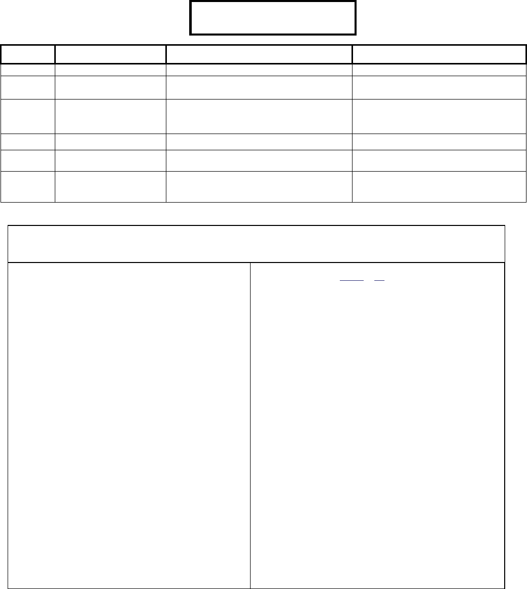
21-3602E rev1.5 Monitor xL™ Advanced Installation Guide 49
Program Section: T080 (Custom Inputs)
T08000 Keypad Selections
(left to right on keypad screen) Example:
Default Name Selections Description
0 Level 0: 24 hr, 1: Stay & On, 3: On Only When the input will be monitored.
00 Characteristics See Custom Input Characteristic Types
list.
What the special input will do.
(UK ACPO custom point # 1 = 40, # 2 = 10)
0 Class 0: Fire Class A (Double Loop); 1: Fire;
2: Hold Up; 3: Aux. Alert; 4: Vault /
Safe; 5: Burglary; 6: Supervisory
How the input will report to the Monitoring
Station.
(UK ACPO custom point # 1 = 6, # 2 = 5)
(no) Bypassable (yes) □(no) Can this input be bypassed?
(no) Chime (yes) □(no) Will this input cause keypads to sound
when it is opened? (E.g. entry door)
(no) Pre-Alarm Warning (yes) □(no) Will this input supply a warning alert
delay (keypad sounds), so it can be reset
before reporting to the Monitoring Station
Custom Input Characteristic Types
Characteristic Types: 00: Entry/Exit Door; 01: 1 sec(s); 02: 2s; 03: 3s; 04: 5s; 05: 10s; 06: 15s; 07: 20s; 08: 30s; 09: 45s;
10: 60s; 11: 90s; 12: 2 min(m); 13: 3m; 14: 5m; 15: 10m; 16: 15m; 17: 20m; 18: 30m; 19: 45m; 20: 60m; 21: 90m; 22: 2 hr(h); 23:
4h; 24: 6h; 25: 8h; 26: 10h; 27: 12h; 28: 16h; 29: 20h; 30: 1 day; 31: 1 week; 32: garage; 33: E/E route; 35: FAP (6sec/20min); 37:
E/E route FAP; 39: Activity Monitor; 40: Command Point; 41: Arming Keyswitch; 42: Guard Tour Point; 43: Work Late Function.
Entry/Exit Doors: The 'Entry/Exit Door' selection (characteristic
type = 00) is normally used with doors that are monitored, but not
electronically controlled for personnel access. For access-
controlled doors, a dedicated 'Door Contact' input is provided on
the door-control module (which does not need to be set up as an
input point). Readers & doors are set up via R001 - R032.
Also, an E/E door type-of-point cannot be set for a 24-hr
monitoring level (this will 'undefine' the custom point type). As
well, with E/E doors, the custom bypass selection can be applied
to a custom E/E door type to make it bypassable.
Garage Points: The 'garage' selection (type = 32) refers to
garage door sensors. With these inputs, the 'garage' delay setting
will apply (see A0xx:01), and the area can be armed while the
point is tripped (the garage sensor will be armed after the door is
closed).
FAP: (False Alarm Preventor) If a FAP input is not OK longer than
10 seconds, an alarm condition occurs. If a FAP input is triggered
and immediately resets, a 20 minute timer begins. If the same
device is tripped or a different FAP device trips in the same 20
minutes, an alarm occurs.
Activity Monitor: activation informs the system that the area this
point is connected to is still occupied. Used in conjunction with
A0xx:07.
Activity Monitor and Custom Point Type “Level” selections: 0:
24hr: – 24 hr Activity Monitor – activity point always active (ON,
STAY and OFF). 1: Stay & On – Activity Monitor when area OFF,
standard alarm when in STAY and ON. 3: On Only – Activity
Monitor when area OFF & STAY, standard alarm when ON.
Command Point: Command Points are only configurable through
the Director software. WARNING: Never attempt to edit a
Command point name at a keypad or it may fail to operate.
Keyswitch Operation: If the type is set to 41 (Keyswitch), the
'level' setting specifies whether the switch will arm (1), or disarm
(0) the area associated with the specific input point. Furthermore,
if the custom-type is set to "Chime ()", and the area is set for
"Stay on Fail to Exit", the area will be armed to 'Stay' if no users exit
after turning the switch (not-Ok to Ok).
Conversely, if the custom-type is set to NOT chime (), the "Stay on
Fail to exit" setting will be ignored (the area will fully arm to 'On').
Note: With an arming keyswitch, disarming is typically done through
an LCD keypad.
Guard Tour Points: For an input point to be used in a guard tour, it
requires a custom point type with the 'type' set as 42 (Guard Tour
Point). For this application, the 'class' should be set as "Supervisory",
and the 'level' will typically be set as "24 hr". Also note that, in this
case, any "TX" selections will be ignored (guard-tour point activity is
referenced only by the Director software during the guard tour).
Work Late Function: This custom type can be assigned to e.g. a
motion detector in an area that is off but is in its LCD keypad, closing
time warning, at the last 15 min of its schedule. If this motion detector
is tripped because area occupants are working late, it will delay the
scheduled closing time. To set the Worklate Time Extension for 'work
late' points in an area, refer to A0xx:01 under "A001 - A016 (Areas
and Related Settings)". NOTE: The Custom Type “Level” can only be
set to “Stay & On” or “On” for this point. Setting it for 24hr will result in
repeated alarms. When the area is armed, this pt type converts to a
standard burg point.
Chime: This setting is often used with Entry points/routes (so
persons know that someone has entered the area).
Pre-Alarm Warning: For associated input-points, alarm
transmission (to the central station) will be delayed as per the "Pre-
Alarm Delay" setting (for the specific 'area'). During the delay,
keypad sonalert(s) will be sounded, giving an authorized user time to
"Silence" the alarm at a keypad. (Selecting "Verify User" will cancel
the alarm transmission.)
To set the "Pre-alarm Delay" time for a specific area, refer to A0xx:01
under "A001 - A016 (Areas and Related Settings)". To set the areas
to be monitored by a specific keypad, refer to M0xx:01 under "M001 -
M024 (Modules and Related Settings)".
0·
0
0·
0
· ······
Save T08000
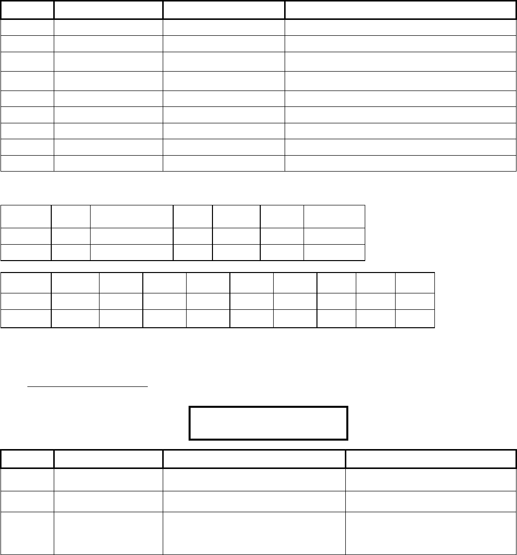
50 Monitor xL™ Advanced Installation Guide 21-3602E rev1.5
T08001 How the input will behave when it is active.
Keypad Selections (left to right on keypad screen)
Default Name Selections Description
(no) Transmit in OFF (yes) □(no) Reporting to the Monitoring Station
(no) Transmit in STAY (yes) □(no) Reporting to the Monitoring Station
(no) Transmit in ON (yes) □(no) Reporting to the Monitoring Station
(UK ACPO custom point # 2 = yes)
(no) Sonalert in OFF (yes) □(no) Keypad sounder active.
(UK ACPO custom point # 2 = yes)
(no) Sonalert in STAY (yes) □(no) Keypad sounder active.
(no) Sonalert in ON (yes) □(no) Keypad sounder active.
(no) Siren in OFF (yes) □(no) System siren active.
(no) Siren in STAY (yes) □(no) System siren active.
(no) Siren in ON (yes) □(no) System siren active.
Default UK ACPO Custom Input Settings (T08000 and T08101)
Custom
Input Pt.
Level Characteristic
Type
Class Bypass Chime Pre-Alarm
T080 0 40 6
□(no) □(no) □(no)
T081 0 10 5
□(no) □(no) □(no)
Custom
Input Pt.
Transmit
OFF
Transmit
STAY
Transmit
ON
Sonalert
OFF
Sonalert
STAY
Sonalert
ON
Siren
OFF
Siren
STAY
Siren
ON
T080 □ (no) □ (no) □ (no) □ (no) □(no) □(no) □(no) □(no) □ (no)
T081 □ (no) □ (no) (yes) (yes) □(no) □(no) □(no) □(no) □ (no)
Program Section: R001 (Doors)
WARNING: R00100 – R00114 Access Control related selections are only available with the addition of
the “Feature Expansion Board”.
R00100 Keypad Selections
(left to right on keypad screen) Example:
Default Name Selections Description
00 Access Module
Number
00 = Door undefined
01-24=Access Pod Module #
The door controller module associated
with this reader/door.
blank Door Name 12 alpha-numeric characters A suitable name/description for this
reader/door.
1 Module Door
Port Number
1 or 2 The 1st or 2nd door on the door controller
module. This is indicated on the PCB.
Tip: This is 1 for odd-numbered doors,
and 2 for even-numbered doors.
Note: The second door on each door controller module is configured separately (typically R002, R004, etc.).
00· Door Name
1
Save R00100

21-3602E rev1.5 Monitor xL™ Advanced Installation Guide 51
R00101,04 Keypad Selections
(left to right on keypad screen) Example:
Default Name Selections Description
(yes) 1s
t
Reader Defined (yes) □(no)
01 Reader Area 2 Digits
01 – 16
00 – outside area
This is the area being entered by this
reader.
000 Card Lockout
Schedule
00 = No scheduled lockout
01 – 250 Schedule
A schedule to specify when card
access will be blocked.
0 Enable / Disable Card
Type (Card Action)
00 = None, 01=Escort Req’d, 02 =non-
permanent users, 03 =all users.
Escort e.g. guard to take visitors around
0 Enable / Disable
Reader Type (Card
Action)
If enabling reader, see *1 Note below.
If disabling reader, see *2 Note below.
Reader enrolls or deletes cards.
(yes) Arming Station (yes) □(no) (UK ACPO = yes)
(no) Lockout In Schedule (yes) □(no)
(no) Enable / Disable
Reader (Card Action)
(yes) □(no) See Notes 1 & 2 below.
(no) Unlock on Enable /
Disable (Card Action)
(yes) □(no) The reader door will unlock when a
card is enabled or disabled at the
reader.
Note *1: If enabling reader, 0=enable for 4 hrs, 1=enable for 8hrs, 2=enable for 12 hrs, 3=enable for 24 hrs, 4=enable
for 1 week, 5=enable until midnight tonight, 6=enable permanently, 7=enable until out of window according to
schedule 50.
Note *2: If disabling reader, 0=disable card permanently, 1=disable card but set it so that it can be re-enabled later at
an enabling station, 2= disable card permanently and trigger auxiliary output , 3= disable card enable re-enroll
and trigger auxiliary output, 4 to 7 = not used, same as 1 (room for future expansion)
·01·000·0·0·
Save R00101

52 Monitor xL™ Advanced Installation Guide 21-3602E rev1.5
R00102, 05 Keypad Selections (left to right on keypad screen)
Default Name Selections Description
000 Reader Class Map
Schedule
00 = Treat as In Schedule
01 – 250 Schedule
Enter a schedule for reader-class
restriction.
00 Group Number 00 = none, 1 – 63, Reader Group
Number.
(yes) In Schedule A (yes) □(no) Whether Class A users can enter during
schedule
(yes) In Schedule B (yes) □(no) Whether Class B users can enter
during schedule
(yes) In Schedule C (yes) □(no) Whether Class C users can enter
during schedule
(yes) Out of Schedule A (yes) □(no) Whether Class A users can enter
outside of the sched.
(yes) Out of Schedule B (yes) □(no) Whether Class B users can enter
outside of the sched.
(yes) Out of Schedule C (yes) □(no) Whether Class C users can enter
outside of the sched.
(no) Anti-pass Back (yes) □(no) Whether cards are to be blocked
against re-entry before exiting first.
(no) Log APB Violation
Only
(yes) □(no) Whether 'Anti-pass Back violators'
will be granted entry.
(yes) Enable Class
Checking
(yes) □(no) Door class (A,B,C) checking, on or
off.
R00103,06 Keypad Selections
(left to right on keypad screen) Example:
Default Name Selections Description
000 Card Mode Schedule 00 = Use as In Schedule setting
01 – 250 (Schedule)
Enter a schedule to allow cycling
between different 'card' modes during the
daytime, vs. after-hours.
000 Reader Mode
Schedule
00 = Use as In Schedule setting
01 – 250 (Schedule)
Enter a schedule to allow cycling
between different reader modes during
the daytime, compared with after-hours.
2 Card Mode In
Schedule
0=Card only,1= Card + PIN, 2= Card or
UID/ PIN,3= UID/ PIN only
The basic method that entrants will have
to use to gain entry at this door—i.e., via
access token and/or by keying-in a PIN.
2 Card Mode Out of
Schedule
0=Card only,1= Card + PIN, 2= Card or
UID/ PIN, 3 = UID/ PIN only
Same as ‘Card Mode In Schedule’
0 Reader Mode In
Schedule
0=Normal,1= Dual Custody, 2= Escort,
3= Toggle Lock all user, 4= Toggle lock
authorized. 5–7=Future
Sets whether a second user, or initial
escort will be required to gain entry (while
the schedule is active).
0 Reader Mode Out of
Schedule
0=Normal,1= Dual Custody, 2= Escort,
3= Toggle Lock all user, 4= Toggle lock
authorized. 5–7=Future
Sets whether a second user, or initial
escort will be required to gain entry
(outside of the schedule).
(Schedules): Select "00" to have the "During Schedule" selection apply all of the time.
To set up schedules or view related settings, refer to "D001 - (Schedules for Area/Access/Door Automation)".
Card Mode: For "ID/PIN only", an access token is NOT required, and the entrant must enter either their PIN or ID+PIN. For an armed area that is
NOT set to 'Auto Disarm on Valid Token', the user will also have to access the alarm system and disarm the area. For details on ‘Auto Disarm on
Valid Token’, refer to A0xx:04 (Areas and Related Settings)".
Reader Mode: For access to be granted when dual custody is in effect, two users who have the authority to enter the specific door at the present
time must present their card and/or PIN at the reader. With escort mode, the second user must have "Escort" authority. (A valid 'escort' can also
enter on their own by presenting their card/PIN twice.) To assign escort authority to a block of users (i.e., those assigned to a specific authority
level), refer to I00102 (Authority Levels for Users/Entrants)". Tip: "Dual Custody" is also supported referring to disarming an area. For details,
refer to A0xx02 (Areas and Related Settings)".
000
·
0
00
·
2
·
2
·
0
·
0
·
Save R00103

21-3602E rev1.5 Monitor xL™ Advanced Installation Guide 53
R00107 Keypad Selections
(left to right on keypad screen) Example:
Default Name Selections Description
04 Unlock Time 00-31 (Delay Table)
04 = 5 Sec
The unlock duration when a user is
granted entry.
06 Challenged Unlock
Time
00-31 (Delay Table)
06 = 15 Sec
The unlock duration when access is
granted for a physically challenged user.
Whether or not the 'Challenged' unlock
time applies is based on the 'Challenged'
setting for the user. For details, refer to
U00102 (User Name and Basic
Settings)
0 Door Alarm
Monitoring
0=None
1=Door Held Open Processing, 2=Door
Forced processing,
3=Door Held
Open and Door Forced
Processing
Whether or not this door is to be
monitored for forced entry and/or being
held open too long.
(yes) Reader LED Mode = BiColor = Normal
Set this as yes for arming stations,
and for any readers with a bicolour LED.
(no) RTE Required
(request to Exit)
(yes) □(no) Whether or not the RTE input will be
used / monitored.
(no) Panel Process RTE (yes) □(no) Sets the main panel to control RTE pro-
cessing instead of the door controller
(no) Do Not Unlock Door
On Process RTE
(yes) □(no) This setting is used with "Interlocked"
doors that are equipped with an RTE
button e.g. PIR RTE. For details on the
'interlock' feature, refer to R00111
(no) Log RTE (yes) □(no) Whether 'RTE presses' are to be
recorded.
(no) Turn Style (yes) □(no) Escort can use card 2n
d
time to enter
after using once to validate at Anti-Pass
Back door.
(no) Entry Detection (yes) □(no) Second try at Anti-Pass Back door if first
unlock missed. I.e. door was not opened
at 1st unlock.
RTE = “Request to Exit”
04· 06· 0·
·
Save R00107

54 Monitor xL™ Advanced Installation Guide 21-3602E rev1.5
R00108 Keypad Selections
(left to right on keypad screen) Example:
Default Name Selections Description
06 Door Held Open Time 00-31 (Delay Table)
06 =15 Sec
How long the door can be held open after
access is granted without causing an alarm.
10 Challenged Door Held
Open Time
00-31 (Delay Table)
10=1 Min
How long the door can be held open without
causing an alarm after a physically-
challenged user enters. Whether or not the
'Challenged' door held open time applies is
based on the 'Challenged' setting for the
user. For details, refer to U00102
(“Physically Challenged“ Setting).
14 Auxiliary Relay Output
Time
00-31 (Delay Table)
14=5Mins
How long the door can be held open after
access is granted without causing an alarm.
0 Auxiliary Input Mode 0=None, 1=Mag Lock Bond Sense,
2=Challenged RTE,
3= (future) Panel Control
This specifies how the auxiliary input on this
door-controller module is to be used.
0 Auxiliary Relay Output
Mode
0=None, 1=Door Held Open / Door
Forced **, 2=Door Opener *,
3=future
Operation of the alarm relay on the door-
controller module
(no) Reader Tamper
Required
(yes) □(no) Whether or not this reader tamper input is to
be monitored.
(no) Reader tamper as
Panel Input
(yes) □(no)
* Will fire output in this mode when auxiliary input mode is set to challenged RTE and auxiliary input is activated.
** Will fire output in this mode when the condition specified in Door Processing Mode is detected.
R00109 Keypad Selections (left to right on keypad screen)
Default Name Selections Description
00 Door Forced / Held
Time
00-31, Global Delay Table
0 Door Circuit 0=NC
1=NC/EOL
2=NO/EOL & Form-C SEOL
3=Form-C DEOL
The type of circuit/wiring being used with
the door contact.
0 RTE Circuit
(request to exit)
0=NC
1=NC/EOL
2=NO/EOL & Form-C SEOL
3=Form-C DEOL
The type of circuit/wiring being used with
the RTE input.
0 Reader Tamper Circuit 0=NC
1=NC/EOL
2=NO/EOL & Form-C SEOL
3=Form-C DEOL
The type of circuit/wiring being used with
the reader tamper.
0 Auxiliary Circuit 0=NC
1=NC/EOL
2=NO/EOL & Form-C SEOL
3=Form-C DEOL
The type of circuit/wiring being used with
the aux. input.
(no) Do Not Lock on Door
Closure
(yes) □(no)
(no) Insertion Reader (yes) □(no)
(no) Force Door Buzzer
stops on Closure
(yes) □(no)
Legend: 0 = NC: Circuit type 0 (Normally Closed), 1 = NC/EOL: Circuit type 1 (Normally Close with EOL), 2 = NO/EOL:
Circuit type 2 (Normally Open with EOL and Form C Single EOL), 3 = Circuit type 3 (Form C Dual EOL).
06·
1
0·
1
4·
0
·
0
· ····
Save R00108

21-3602E rev1.5 Monitor xL™ Advanced Installation Guide 55
R00110 Keypad Selections
(left to right on keypad screen) Example:
Default Name Selections Description
000 Unlock Mode
Schedule
000 = Treat as In Window setting
001 – 050 (Schedule)
Enter a schedule for automated door
unlocking.
0 Unlock In Schedule 0=Lock, 1=Unlock, 2=Pending First
User, 3=Area is OFF, 4=Area Stay/OFF
The unlock mode for while the schedule
is active (or 24 hrs).
0 Unlock Out of
Schedule
0=Lock, 1=Unlock, 2=Pending First
User, 3=Area is OFF, 4=Area Stay/OFF
The unlock mode for after-hours (outside
of the sched.)
1 Arming Level 0=Not legal, 1= Stay/On 2= Future 3= On
only
Select the area arming levels for this
door to be monitored.
2 Token Format 0=none, 1=future (dallas), 2=weigand
3=mag
This is the type of tokens and
readers assoc. with this door.
(no) Detect Wandering
Patient
(yes) □(no) Enable wandering patient(s)
detection.
(no) Lock On Wandering
Patient
(yes) □(no) This allows having the door lock when a
wandering patient is detected.
(no) In/Out Station (yes) □(no) For a reader used to log personnel
entries & exits only. This refers to a 'time-
clock' or 'In/Out Status' application for a
reader that is typically NOT wired to a
door lock.
R00111 Keypad Selections (left to right on keypad screen)
Default Name Selections Description
(no) Interlock Required (yes) □(no) A second interlock door can not be
opened until the interlock door that
was first opened is closed.
01 Interlocked Door 1 2 Digits 00 – 32 00 - No interlock 1-32
(Door Number)
01 Interlocked Door 2 2 Digits 00 – 32 00 - No interlock 1-32
(Door Number)
01 Interlocked Door 3 2 Digits 00 – 32 00 - No interlock 1-32
(Door Number)
06 Interlock Delay 00-31 (Delay Table) 06 = 15 Sec
R00112 Keypad Selections Held Open Door Processing (left to right on keypad screen)
Default Name Selections Description
(no) Held Open Processing
Transmit Off (yes) □(no)
(no) Held Open Processing
Transmit Stay (yes) □(no)
(no) Held Open Processing
Transmit On (yes) □(no)
(no) Held Open Processing
Siren Off (yes) □(no)
(no) Held Open Processing
Siren Stay (yes) □(no)
(no) Held Open Processing
Siren On (yes) □(no)
(yes) Held Open Processing
Alert Off (yes) □(no)
(yes) Held Open Processing
Alert Stay (yes) □(no)
(yes) Held Open Processing
Alert On (yes) □(no)
000
·
0
·
0
·
1
·
2
· ·
Save R00110

56 Monitor xL™ Advanced Installation Guide 21-3602E rev1.5
R00113 Keypad Selections Forced Open Door Processing
(left to right on keypad screen) Example:
Default Name Selections Description
(no) Forced Open Processing
Transmit Off (yes) □(no)
(no) Forced Open Processing
Transmit Stay (yes) □(no)
(no) Forced Open Processing
Transmit On (yes) □(no)
(no) Forced Open Processing
Siren Off (yes) □(no)
(no) Forced Open Processing
Siren Stay (yes) □(no)
(no) Forced Open Processing
Siren On (yes) □(no)
(yes) Forced Open Processing
Alert Off (yes) □(no)
(yes) Forced Open Processing
Alert Stay (yes) □(no)
(yes) Forced Open Processing
Alert On (yes) □(no)
R00114 Keypad Selections Magnetic Lock Alarm Processing (left to right on keypad screen)
Default Name Selections Description
(no) Mag Lock Processing
Transmit Off (yes) □(no)
(no) Mag Lock Processing
Transmit Stay (yes) □(no)
(no) Mag Lock Processing
Transmit On (yes) □(no)
(no) Mag Lock Processing
Siren Off (yes) □(no)
(no) Mag Lock Processing
Siren Stay (yes) □(no)
(no) Mag Lock Processing
Siren On (yes) □(no)
(yes) Mag Lock Processing
Alert Off (yes) □(no)
(yes) Mag Lock Processing
Alert Stay (yes) □(no)
(yes) Mag Lock Processing
Alert On (yes) □(no)
· · ·····
Save R00113

21-3602E rev1.5 Monitor xL™ Advanced Installation Guide 57
The following program sections are only applied using the Director Software and Feature
Expansion Board. Displays in these keypad programming screens are for viewing only.
C001 - C060 (Suite Security LED Keypads)
Suite Security LED keypad modules provide security and monitoring features for up to 60 individual suite units
associated with a specific main panel. 8 Zone suite security LED keypads support 8 monitored sensors/inputs,
2 programmable outputs, and 3 'panic keys'. '2 Zone' LED units support 2 monitored sensors/inputs, one panic
key, and one programmable output.
These "Suite Security" keypads can be set up only through the Director Software (subject to your software
version and licensing agreement). For details, refer to the on-line help or User's Guide for your Director
Software.
Each panel supports all 8 zone or 2 zone or a mixture of both at a maximum of 60 Suite Security LED keypads (with no other
modules). If suite security LED keypads are to be mixed with other modules, the suite security capacity will be reduced by 5 for
each system LCD keypad, and each other expansion / application module that is added. (For example, with 2 system keypads,
3 door controllers, and one point expansion module, a full-capacity "Enterprise" system could still support 30 suite security units).
Suite Security units are not associated with any system 'Areas' or related schedules or settings. All settings that affect suite
security-keypad operation are defined through the "Suite Security" screen of the Director Software. Suite Security LED keypads
are NOT associated with the "Module" screens in any way.
UL / ULC Listed Installations: UL and ULC testing is pending on suite security LED keypads and related features.
V001 - V032 (Elevators/Lifts)
Elevator controller modules provide security and monitoring features for elevator (lift) cabs and associated
floors. These units can be set up only through the Director Software (subject to your software version and
licensing agreement). For details, refer to the on-line help or User's Guide for your Director Software.
Each system can include up to 32 elevators, and a total of up to 124 access-controlled floors. Exception: The elevator capacity
is shared with doors (max. 32 combined). Doors also share the elevator numbering (and panel memory space). Numbers
already defined as doors will not be available for elevators.
With access-controlled elevators, floor call-buttons are disabled until an authorized person presents their access card. When the
card is presented, the specific floors for that person will become available.
UL / ULC Listed Installations: As of this writing, UL and ULC testing is pending on elevator (lift) controllers and related features.
F001 - F124 (Floors)
Systems with elevator controllers can include up to 124 access-controlled floors. These can be in a single
building, or the combined total for multiple buildings. Elevator controllers and floors can be set up only through
the Director Software (subject to your software version and licensing agreement). For details, refer to the on-line
help or User's Guide for your Director Software.
Floors can be set to allow free access during certain times based on a chosen schedule. As well, the status & control feature of
the Director Software allows manually setting floors to allow free access, or apply controlled-access, as desired.
UL / ULC Listed Installations: As of this writing, UL and ULC testing is pending on elevator (lift) controllers and related features.
Condominium

58 Monitor xL™ Advanced Installation Guide 21-3602E rev1.5
Z001 - Z003 (Shared User Data)
Allows Users, Authority Levels and Holidays to be shared across multiple accounts using Director version 4.2.
With Director V4.2, this feature is limited to panel feature-set 2, 3, and 4 (1 panel per account, max. 1000 users,
etc.). Information for this type of system set-up is available in the v4.2 Director’s User Guide.
Shared Users, Authority Levels and Holidays are considered to be under Director control and not panel control.
Programming for this selection is not done in the LCD keypad configuration screens. Programming is only done
for these selections with the use of the Director software and sent to the panel.
Initiating a “Get from Panel” from the Director software cannot be done for the following reasons:
Shared Users and Holidays
If changes for these selections have been made at the panel using an LCD keypad and a Get from Panel is done
at the Director software, the new information in the panel will be ignored and overwritten with the server’s old
information.
Shared Authority Levels
Shared Authority Levels that are not in the panel, will have any new information that has been entered into the
server data base for their Areas and Schedules cleared.
Panels with Firmware Earlier than v4.2 and a Get from Panel is Done:
1. If a Shared User has been edited at the panel, only their PIN will be updated. The server will replace any of the
other user’s data with the server’s old information.
2. If a Shared Authority Level is deleted at the panel, any new and valid information for the Authority Level’s Areas
and Schedules will be cleared at the server and the panel.
Keypad Operations at Panels with v4.2 Firmware
1. Only a Shared User’s PIN can be edited at the panel and only by that Shared User.
Shared Authority Levels cannot be deleted at the panel.
Premises IP Module HSC-IP Receiver Communications
Programming Sections
Program Section: N001 (Network)
Program Section: J001 (HSC-IP Communications)
Program Section: K001 (HSC-IP Communications with MONITOR ISM/xL)
Refer to Installation Instructions 21-3691E for these programming selections.
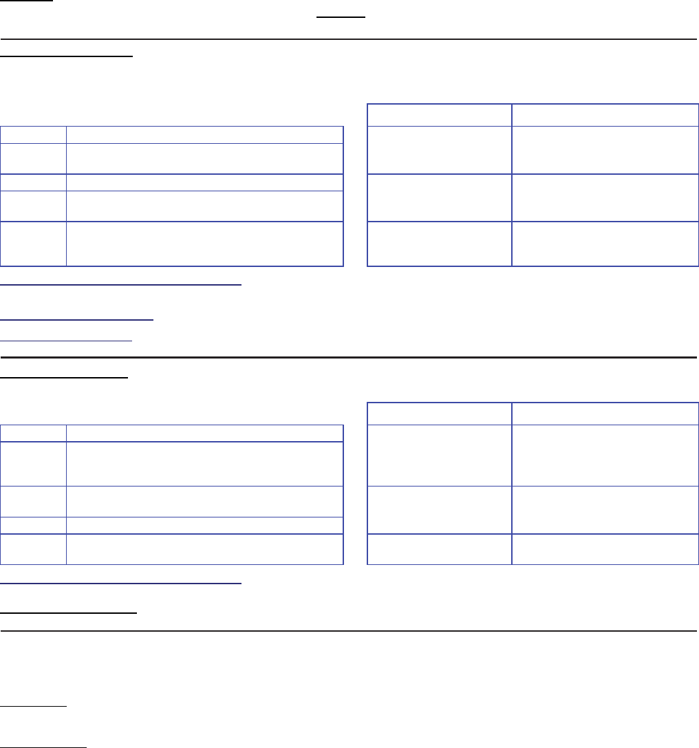
21-3602E rev1.5 Monitor xL™ Advanced Installation Guide 59
Transmitted Messages (SIA & Contact-ID)
General Message Format
Messages are transmitted to the monitoring station using either the "SIA Level II" or "Contact ID" format.
NOTICE: The message formats described here are NOT to be confused with messages provided by the
receiver software. (Those messages will typically include the information discussed here, along with date/time
information and proprietary formatting.)
SIA Level II Format
Messages that reference an area: N riSSSS / XX PPP
System Messages (no area reference): N XX PPP
Where: Sample Messages Meaning
N This indicates a "new event". N ri2 / BA 227 Burg. alarm associated with
area 2; door 27. (Also see
"Door Activity", to follow.)
Ri This indicates "area" (i.e., the next number is
an area reference).
SSSS This is the area number/ID. N ri4 / BA 73 Burg. alarm associated with
area 4; input-point 73.
XX This is a two-character SIA alarm code (refer to
the SIA message list).
PPP This is the number/ID for the input point or user
associated with the event, or optional
information (depending on the type of event).
N UX2 Digital dialer communications
test signal.
When creating an account message template: Enter only the two-digit SIA code.
(The "N" is processed automatically by the receiver.)
Account Number Information: This is sent in another message-type, and is automatically understood by the receiver software.
User IDs 998 and Higher: The SIA format supports unique user numbers up to 997 only (998 and above will appear as "998").
User ID "999" is considered to be the "automatic user"--which means an event that was triggered by the system.
Contact ID Format
All CID-Format Messages: CCCC QEEE GG ZZZ
Where: Sample Messages Meaning
CCCC The account number 1234 1110 02 003 Account 1234, Fire Alarm
detected in area 02 by
input-point 003.
Q An event qualifier: "1" is a new event (shown
as "E" in the contact-ID message list), and "3"
means a restoral (shown as "R" in the list).
EEE This is a three character CID alarm code (refer
to the Contact-ID message list).
1234 1301 01 000 Account 1234, AC trouble
(reported as Area 1 by default)
GG This is the "area" number/ID.
ZZZ This is the number/ID for the input point (zone)
or the user associated with the event.
1234 3301 01 000 Account 1234, AC restoral
(reported as Area 1 by default)
When creating an account message template: Enter only the three-digit CID code.
(The leading event qualifier is processed automatically by the receiver.)
User IDs 998 and Higher: The CID format supports unique user numbers up to 997 only (998 and above will appear as "998").
User ID "999" is considered to be the "automatic user"--which means an event that was triggered by the system.
Door Activity
Access-controlled doors report burglar or tamper alarms as regular access door input numbers 201 through 232 for Monitor ISM
systems and 501 through 532 for Monitor xL systems when an area is armed. The leading digit “2” defines the activity as a
burglary type alarm. The secondary two digits identify the door ID/numbers 1 to 32.
Door Forced alarms report as “burgs” but are identified by the leading digit: 3. If "door forced" is configured, it reports as "3" when
the area is disarmed. It will report as a "2" followed by a "3" ("door forced" if configured) when an area is armed. 301 to 332 are
door-forced alarms for doors: 1 - 32.
Door Held Open alarms report as “burgs” but are identified by the leading digit: 4. If "door held open" is configured, it reports as "4"
when the area is disarmed. Like "door forced", it is possible to receive a "2" (burg) followed by a "4" ("door held", if configured)
when an area is armed. 401 to 432 are door held open alarms for doors: 1 - 32.
However, when an area is armed, it is not possible to receive a 2, 3 and a 4. If a door is forced, a 2 and a 3 are received. If a door
is opened by an access device and held open, a 2 and a 4 are received. Similarly, restores for these alarms report as “burg
restore” for door point alarms: 201 - 232, door forced alarms: 301 - 332 and door held open alarms 401 - 432.

60 Monitor xL™ Advanced Installation Guide 21-3602E rev1.5
Event Message Reference: Sorted by SIA Code
SIA CID equiv. Description / Meaning Level
AR R301 AC Trouble (E003--Restore) Emergency
AT E301 AC Trouble (E003) Emergency
BA E130 Burglary Emergency
BR R130 Burglary --Restore Emergency
BS E155 Point-Test Fail Emergency
BT E383 Burglary --Tamper Emergency
CA R403 Automatic Area On (Sched. auto-arm on fail to close) Full
CE E405 Work late (Closing extended) Emergency
CF R402 Turn Area On (Bypass or Forced) Full
CI E453 Fail to Turn Area On (Fail to Close) Emergency
CL R401 Turn Area On (Normal) Full
DG E422 Second User Authority Granted for Dual Custody Full
DU E458 Verify User Emergency
EE E134 Fail to Exit Area Emergency
ER R143 Module tamper/comms/subst'n (E011--Restore) Emergency
ET E143 Module Trouble--tamper/comms/subst'n (E011) Emergency
FA E110 Fire or Fire-Class A Emergency
FR R110 Fire or Fire-Class A--Restore Emergency
FT E380 Fire or Fire-Class A--Tamper Emergency
HA E121 Duress Pin Emergency
JR E404 Schedule resumed (Stay opened resume) Emergency
JS E459 Schedule suspended (Stay opened suspended) Emergency
JT E625 Time Changed (E007) Emergency
LB E306 Main panel Config Changed (E008) Emergency
LR R351 Phone Trouble (E004--Restore) Emergency
LS R330 Main panel Program Error (E009--Restore) Emergency
LT E351 Phone Trouble (E004) Emergency
LU E330 Main panel Program Error (E009) Emergency
LX R306 Main panel Config Changed (E008--Restore) Emergency
MA E100 Aux. Alert Emergency
MR R100 Aux. Alert--Restore Emergency
MT E380 Aux. Alert--Tamper Emergency
NF R456 Turn Area to Stay (Bypass or Forced) Full
NK+ R407 Emergency Stay Out of Schedule Emergency
NL R408 Turn Area to Stay (Normal) Full
NR+ R457 Unauthorized Stay If No Emergency Off Emergency
OA E409 Automatic Area Off (SDC5 type points) Full
OG R441 Turn Area to Stay from On Full
OK E451 Emergency Off (schedules) Emergency
OP E401 Turn Area Off Full
OR E450 Unauthorized Off (schedules) Emergency
PA E120 Holdup Emergency
PA or E120 with event
code “199” for Monitor ISM
and “299” for Monitor xL
Global Lockout Alarm caused by invalid card/PIN use in Area. Emergency
PR R120 Holdup--Restore Emergency
PA or E120 with event code
“199” for Monitor ISM and
“299” for Monitor xL
Global Lockout Alarm Restore in Area. Emergency
PT E380 Holdup--Tamper Emergency
QA E140 Vault/Safe Emergency
QR R140 Vault/Safe--Restore Emergency
QT E380 Vault/Safe--Tamper Emergency

21-3602E rev1.5 Monitor xL™ Advanced Installation Guide 61
(SIA codes--continued from preceding page)
RB E380 Module Program Changed (E013) Emergency
RC R354 Misc Trouble (E015--Restore) Emergency
ri n/a Area-number reference Emergency
RN R380 Module Program Changed (E013--Restore) Emergency
RO E354 Misc Trouble (E015) Emergency
RR E305 Time Lost (E006) Emergency
RS R145 Module Program Error (E014--Restore) Emergency
RU E145 Module Program Error (E014) Emergency
TA E300 Main panel Tamper (E001) Emergency
TR R300 Main panel Tamper (E001--Restore) Emergency
TS E607 Walk or Holdup Test Started (no msg at end of test) Emergency
UA E150 Misc/No Type Emergency
UR R150 Misc/No Type--Restore Emergency
UT E380 Misc/No Type--Tamper Emergency
UX0 E354 Digital Dialer Comms Failure (Messages Lost) Emergency
UX1 E356 Security IP Comms Failure (Messages Lost, Sync Lost, Reset) Emergency
UX2 E602 Digital Dialer Comms Test Emergency
XR R384 Module Battery Low--e.g. wireless xmitr (E012--Restore) Emergency
XT E384 Module Battery Low--e.g. wireless transmitter (E012) Emergency
YC E333 Security IP Comms Trouble (E016) Emergency
YK R333 Security IP Comms Trouble (E016--Restore) Emergency
YM E309 No battery (E002) Emergency
YP E320 Main panel Fuse Failure (E010) Emergency
YQ R320 Main panel Fuse Failure (E010--Restore) Emergency
YR R309 No or low battery (E002--Restore) Emergency
YS E350 Report Delayed, dialer comms trouble (E005) Emergency
YT E302 Low Battery (E002) Emergency
Event Message Reference: Sorted by CID Code
CID SIA equiv. Description / Meaning Level
E100 MA Aux. Alert Emergency
E110 FA Fire or Fire Class A Emergency
E120 PA Holdup Emergency
E120 or PA with event
code “199” for Monitor ISM
and “299” for Monitor xL
Global Lockout Alarm caused by invalid card/PIN use in Area. Emergency
E121 HA Duress Pin Emergency
E130 BA Burglary Emergency
E134 EE Fail to Exit Area Emergency
E140 QA Vault/Safe Emergency
E143 ET Module Trouble--tamper/comms/subst'n (E011) Emergency
E145 RU Module Program Error (E014) Emergency
E150 UA Misc/No Type Emergency
E155 BS Point-Test Fail Emergency
E300 TA Main panel Tamper (E001) Emergency
E301 AT AC Trouble (E003) Emergency
E302 YT Low Battery (E002) Emergency
E305 RR Time Lost (E006) Emergency
E306 LB Main panel Config Changed (E008) Emergency
E309 YM No battery (E002) Emergency
E320 YP Main panel Fuse Failure (E010) Emergency
E330 LU Main panel Program Error (E009) Emergency
E333 YC Security IP Comms Trouble (E016) Emergency
E350 YS Report Delayed, dialer comms trouble (E005) Emergency
E351 LT Phone Trouble (E004) Emergency

62 Monitor xL™ Advanced Installation Guide 21-3602E rev1.5
(CID codes--continued from preceding page)
E354 UX0 Digital Dialer Comms Failure (Messages Lost), or; Emergency
RO Misc Trouble (E015) Emergency
E356 UX1 Security IP Comms Failure (Messages Lost, Sync Lost, Reset) Emergency
E380
FT Fire Class A--Tamper, or; Emergency
FT Fire--Tamper, or; Emergency
PT Holdup--Tamper, or; Emergency
MT Aux. Alert--Tamper, or; Emergency
QT Vault/Safe--Tamper, or; Emergency
UT Misc/No Type--Tamper, or; Emergency
RB Module Program Changed (E013), or; Emergency
E383 BT Burglary --Tamper Emergency
E384 XT Module Battery Low--e.g. wireless transmitter (E012) Emergency
E401 OP Turn Area Off Full
E404 JR Schedule resumed (Stay opened resume) Emergency
E405 CE Work late (Closing extended) Emergency
E409 OA Automatic Area Off (SDC5 type points) Full
E422 DG Second User Authority Granted for Dual Custody Full
E450 OR Unauthorized Off (schedules) Emergency
E451 OK Emergency Off (schedules) Emergency
E453 CI Fail to Turn Area On (Fail to Close) Emergency
E458 DU Verify User Emergency
E459 JS Schedule suspended (Stay opened suspended) Emergency
E602 UX2 Digital Dialer Comms Test Emergency
E607 TS Walk or Holdup Test Started (no msg at end of test) Emergency
E625 JT Time Changed (E007) Emergency
R100 MR Aux. Alert--Restore Emergency
R110 FR Fire or Fire-Class A--Restore Emergency
R120 PR Holdup--Restore Emergency
R120 or PR with event code
“199” for Monitor ISM and
“299” for Monitor xL
Global Lockout Alarm Restore (caused by invalid card/PIN use in Area). Emergency
R130 BR Burglary --Restore Emergency
R140 QR Vault/Safe--Restore Emergency
R143 ER Module tamper/comms/subst'n (E011--Restore) Emergency
R145 RS Module Program Error (E014--Restore) Emergency
R150 UR Misc/No Type--Restore Emergency
R300 TR Main panel Tamper (E001--Restore) Emergency
R301 AR AC Trouble (E003--Restore) Emergency
R306 LX Main panel Config Changed (E008--Restore) Emergency
R309 YR No/Low battery (E002--Restore) Emergency
R320 YQ Main panel Fuse Failure (E010--Restore) Emergency
R330 LS Main panel Program Error (E009--Restore) Emergency
R333 YK Security IP Comms Trouble (E016--Restore) Emergency
R351 LR Phone Trouble (E004--Restore) Emergency
R354 RC Misc Trouble (E015--Restore) Emergency
R380 RN Module Program Changed (E013--Restore) Emergency
R384 XR Module Battery Low--e.g. wireless transmitter (E012--Restore) Emergency
R401 CL Turn Area On (Normal) Full
R402 CF Turn Area On (Bypass or Forced) Full
R403 CA Automatic Area On (Sched. auto-arm on fail to close) Full
R407 NK+ Emergency Stay Out of Schedule Emergency
R408 NL Turn Area to Stay (Normal) Full
R441 OG Turn Area to Stay from On Full
R456 NF Turn Area to Stay (Bypass or Forced) Full
R457 NR+ Unauthorized Stay If No Emergency Off Emergency

21-3602E rev1.5 Monitor xL™ Advanced Installation Guide 63
European and ACPO Installations
Restoring Tampers
Once a tamper condition occurs it will be logged within
the system’s history log. Tampers can be silenced by
any authorized users however, a system message will
scroll on the LCD display to indicate that a tamper
condition had occurred: “Was in Tamper”.
This message can only be cleared during a service call
in the following manner:
i) The main panel cabinet must be opened to activate
the ‘tamper sensor’
ii) The system will generate a tamper alarm; this must
be first silenced by the authorized user.
iii) Next, the Service user ID and Pin must be entered
followed by the ID and Pin of the authorized user.
iv) Close the main panel cabinet to secure the tamper
sensor.
System Conditions that will Block Arming
The system will block arming when the following
conditions are active:
System Tamper
Module Tamper
Module Communications Failure
Prime Power Fault
Battery Fault
Communicator Fault
Detector in active / fault condition
The following conditions that block the arming can be
overridden by the user:
Detector in active / fault condition
Prime power fault
All other blocking conditions must be either corrected or
overridden by a Service Engineer.
ACPO Installation Requirements
The following is required in the UK to ensure
conformity with the DD243:2004 Standard. LCD
Keypad configuration screen numbers are referenced
through out.
Programming:
System
When powering up a new panel, activate the U.K.
functionality. Refer to System Programming
S002:00, “Panel Operation Mode” and select option
“2”.
To allow disarming using ACE as described in the
DD243 standard, the system must be configured for
‘Supports Access + Intrusion’ (Screen S002:01).
This is necessary to generate a Confirmed
Alarm.
Pin Duress must be enabled to signal Personal
Attacks and Holdups. Refer to System Programming
S002:01. Select “ Yes” for “Allow Duress PINS”.
Authority
Auto – Remove Bypass should be set for all user
authority levels to ensure that any automatic
bypasses made as a result of a DD243 are lifted
when the system is disarmed. Refer to Profile
Programming I0XX:01. Select “ Yes” for selection
4: “Auto-Remove Bypass”.
To enable user authorities to Test the siren and
strobe, ensure the “ Yes” is selected for the Test
option in Profile Programming I0XX:0I, selection 5:
“Test”.
Area
‘Stay on Fail to Exit’ must be disabled so that the
system will only arm if the external exit button is
pushed. Refer to Area Programming A0XX:01 and
ensure selection 5 is set as “ No”.
‘Terminate Exit Delay’ must be disabled so that
opening and closing the exit door will not terminate
the exit delay, this should be done by pushing the
exit button to terminate the exit delay. Refer to Area
Group A0XX:01 selection 7 and set as “ No”.
‘Alarm on Fail to Exit’ must be enabled to ensure
that the system will indicate locally if the exit button
has not been pushed. This will disarm the area to off
on failure to exit properly due to not pushing the exit
button. Refer to Area Group A0XX:01 selection 6
and set as “ Yes”.
‘Siren Squawk on Arming’ must be enabled to locally
annunciate arming. Refer to Area Group A0XX:02
selection 4 and set as “ Yes”.
Exit Button
To setup the exit button as required in DD243 a
custom point type must be first created.
Create a custom point type in the Custom Point
Programming T0XX:00 to, Level = 0 (24 hr, Always),
Characteristic Type = 40 (Command Point) and
Class = 6 (Supervisory).
Assign the newly created custom point type to an
appropriate input point. See Input Programming
PXXX:00.
Switched Communicator Line Faults
This system provides capabilities to Enable Line
Failure from switched communicators. This feature is
provided on the World Wide Modem. For details
please refer to Installation Instructions 21-3611.
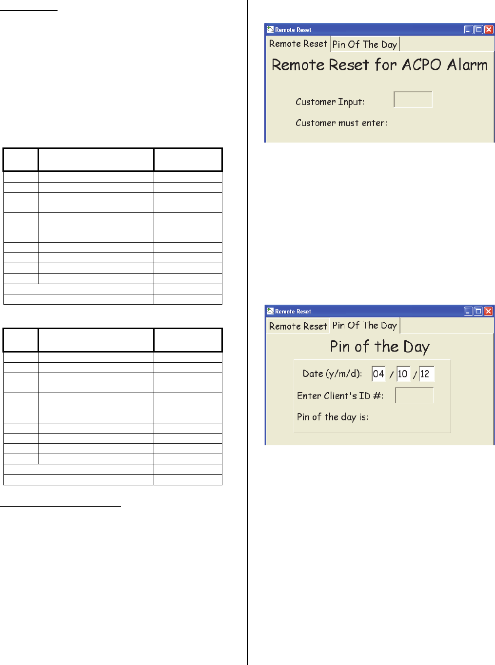
64 Monitor xL™ Advanced Installation Guide 21-3602E rev1.5
Output Points
When using a switched reporting unit such as the ‘BT
Redcare’ the following is recommended:
a) Use the 8 output STU (subscriber terminal unit)
REDCARE Interface on the World Wide Modem to
provide the switched outputs.
b) The switched outputs can be configured to monitor
the system as a whole or monitor just a single area.
The following is the recommended configuration.
See “B001 – B128 Programmable Outputs” section
for output programming instructions.
System Wide
Unit
Input:
Alarm Type: System
Output Code:
1 Fire 59
2 Personal Attack 60
3 Unconfirmed Alarm
(Intruder)
61
4 Set / Unset
Open / Close (Intruder)
– System Setting
62
5 Freezer or Fire Fault 63
6 Circuit Bypassed (Intruder) 64
7 Confirmation (Intruder) 65
8 Spare
System Siren 66
Confirmed Alarm Strobe 67
Area Monitoring
Unit
Input:
Alarm Type: Area Output
Code:
1 Fire 65
2 Personal Attack 66
3 Unconfirmed Alarm
(Intruder)
67
4 Set / Unset
Open / Close (Intruder)
– System Setting
68
5 Freezer or Fire Fault 69
6 Circuit Bypassed (Intruder) 70
7 Confirmation (Intruder) 71
8 Spare
System Siren 63
Confirmed Alarm Strobe 64
Resetting Confirmed Alarms.
Once a confirmed alarm occurs at a site, the user will
be able to disarm and silence the system; the
confirmed alarm strobe output will also turn off.
However, arming will be blocked until reset by an
Engineer during a service call in the following manner:
i) The main panel cabinet must be opened to activate
the ‘tamper sensor’
ii) The system will generate a tamper alarm; this must
be first silenced by the authorized user.
iii) Next, the Service user ID and Pin must be entered
followed by the ID and Pin of the authorized user.
iv) Select “Reset Confirmed Alarm”.
v) Close the main panel cabinet to secure the tamper
sensor.
Remote Reset
For customers who would rather reset the ACPO
alarm themselves, instead of a service/engineer
person attending and doing it.
When the ACPO alarm occurs, the LCD keypad
screen will display a 6 digit code.
The customer notifies the monitoring station with
this number.
The monitoring station enters the number in this
program’s “Customer Input:” box and generates a
response 6 digit number.
The monitoring station gives this response number
to the customer who enters it into the keypad and
can reset the ACPO alarm.
Pin of the Day
For Dealers to protect their sites.
“Pin of the Day” is selected in S00201. A Dealer
ID is entered in program section S00204.
The Dealer notifies the monitoring station for a Pin
of the Day to access the control unit box.
The monitoring station enters the Dealer’s ID
number in this program’s “Enter Client’s ID#:” box
and presses Enter on the computer keyboard. This
will generate a response 6 digit number next to “Pin
of the day is:”.
The monitoring station gives this response number
to the Dealer.
The Dealer tampers the control box by opening its
door.
The Dealer enters the 6 digit Pin of the Day at the
keypad to silence the tamper alarm and can then
begin his work.
This Pin of the Day will last 24 hours from the time it
is initiated at the site.

21-3602E rev1.5 Monitor xL™ Advanced Installation Guide 65
The Date of the Pin of the Day program and the
site’s system date on its keypad must be the same.
UK ACPO Pin of the Day
When a UK system is started up for the first time
and the new system initialization (explained in
Simplified Installation Guide: “Powering On the
System for the First Time”) is done selecting UK as
the region, the service and master user will need to
log on to silence the system.
After which, the date and time will display on the
keypad for entering.
After the date and time are entered and e.g. a
service user has to log on to do programming at the
keypad, as soon as they enter their ID, Pin of the
Day will be requested.
The service user will call the Pin of the Day
program operator who can enter default “24822” as
the new system’s default Dealer ID until a unique
one can be entered at the keypad or downloaded
from the Director software later.
The service user enters random, 6 digit Pin of the
Day number given to them by the operator at the
keypad and can then access the system menus
and configurations.

66 Monitor xL™ Advanced Installation Guide 21-3602E rev1.5
Index
WARNING: Access Control, Elevator and Suite Security selections are only available with the addition of the “Feature Expansion
Board” to the System.
1st Reader Defined ............................................................ 51
3rd Party Password for Main Panel ...................................... 3
5 Digit PIN ............................................................................ 7
AC Brownout Mode .............................................................. 4
AC Reference Voltage .......................................................... 4
AC Sync ............................................................................... 4
Access Auxiliary Circuit ...................................................... 54
Access Door Circuit ............................................................ 54
Access Enable Class Checking .......................................... 52
Access In/Out Station ......................................................... 55
Access Module Door Name ................................................ 50
Access Module Door Port Number ..................................... 50
Access Module Number ..................................................... 50
Access Panic Tokens ........................................................... 7
Access-controlled floors ..................................................... 57
Activity Monitor ................................................................... 49
Activity Timeout .................................................................. 23
Addition Floor ..................................................................... 47
Advanced Program Sections ................................................ 2
Advanced Program Selections ............................................. 2
Advanced Sub Program Sections ......................................... 2
Advanced System Selections ............................................... 2
Alarm On No Activity .......................................................... 23
Allow Port Expanders ........................................................... 5
Allow Un-authorized Open .................................................. 21
Annunciation Map ............................................................... 27
Anti-pass Back ................................................................... 52
Anti-Pass Back Auto Reset ................................................ 22
APB Log Violation Only ...................................................... 52
Area Group Enable ............................................................. 25
Area Group Mode ................................................................. 5
Area Group Mode reference ............................................... 25
Area Group Mode reference ............................................... 42
Area Group Name .............................................................. 25
Area Group Selection ......................................................... 25
Area Input is in ................................................................... 31
Area Name ......................................................................... 19
Area Priority Map ................................................................ 24
Area Schedule .................................................................... 21
Arm/Disarm Map ................................................................ 27
Arming Level ...................................................................... 55
Arming Priority .................................................................... 24
Arming Rules .................................................................. 9, 24
Arming Station .................................................................... 29
Arming Station .................................................................... 51
Authority End ...................................................................... 43
Authority Level .................................................................... 47
Authority Profile Defined? ................................................... 44
Authority Profile Name........................................................ 44
Authority Start ..................................................................... 43
Auto Arm on Door Close..................................................... 20
Auto Arm on Fail to Close ................................................... 21
Auto Disarm on Valid Token In Area Schedule .................. 21
Auto Disarm on Valid Token Out of Area Schedule ............ 21
Auto Disarm to Off Always .................................................. 21
Auto Update Card Version .................................................... 3
Automatic Stay-Mode ......................................................... 21
Automatic Stay-Mode Schedule # ...................................... 21
Auxiliary Input Mode ........................................................... 54
Auxiliary Relay Output Mode .............................................. 54
Auxiliary Relay Output Time ............................................... 54
Badge Access Control ........................................................ 28
Battery Size .......................................................................... 4
Blind Card Re-enrollment ..................................................... 7
Buffer Area? ....................................................................... 31
Burglary Siren Time .............................................................. 2
Card Lockout Schedule ...................................................... 29
Card Lockout Schedule ...................................................... 51
Card Mode In Schedule ...................................................... 30
Card Mode In Schedule ...................................................... 52
Card Mode Out of Schedule ......................................... 30, 52
Card Mode Schedule .......................................................... 30
Card Mode Schedule .......................................................... 52
Card Number ...................................................................... 47
Card Version ....................................................................... 47
Challenged Door Held Open Time ...................................... 54
Challenged Unlock .............................................................. 53
Chime ................................................................................. 49
CID message-format reference........................................... 66
Circuit Band Definitions ...................................................... 18
Circuit Band Name .............................................................. 17
Circuit Band Threshold ....................................................... 18
Circuit Type .................................................................. 17, 31
Class Checking Enable ....................................................... 30
Class Map Schedule ........................................................... 30
Command Point .................................................................. 49
Common to Area Map ......................................................... 24
Communications protocol, SIA and Contact-ID .................. 64
Condo (Suite Security) Baud Rate ........................................ 2
Condominium LED Keypads ............................................... 57
Configurations Phone Number ........................................... 16
Confirm Reset Challenged PIN ............................................. 4
Confirm Reset Master ........................................................... 4
Confirm Reset Service .......................................................... 4
Confirm Reset using Remote ................................................ 4
Confirmed Alarm Time Out ................................................... 4
Contact-ID message-format reference ................................ 66
Custom Dialer Message ..................................................... 18
Custom Input Characteristic Types ..................................... 49
Daytime Phone Number ..................................................... 14
Dealer ID .............................................................................. 9
Default Authority Settings ................................................... 46
Default North American Input Point-Types ......................... 32
Default UK ACPO Custom Input Point-Types ..................... 50
Default UK ACPO Input Point-Types .................................. 32
Delay Screen ........................................................................ 3
Delinquent Arming Threshold ............................................... 5
Dialer Account Number (Daytime) ...................................... 14
Dialer Account Number (Primary) ....................................... 13
Director Service Code 7378 .................................................. 1
Disable Single on Badge-Hold ............................................ 28
Disarm Card + PIN ............................................................. 28
Disarming Priority ............................................................... 24
Disarming Rules ................................................................. 24
Door Alarm Monitoring ....................................................... 53
Door Closure – no locking .................................................. 54
Door Forced / Held Time .................................................... 54
Door Held Open Time ......................................................... 54
Door Number ...................................................................... 28
Dual Custody ...................................................................... 20
Elevators/Lifts ..................................................................... 57
Enable / Disable Card Type ................................................ 51

21-3602E rev1.5 Monitor xL™ Advanced Installation Guide 67
Enable / Disable Reader Type ........................................... 51
Enable / Disable Setting ..................................................... 51
Enable or Disable Cards of Type ....................................... 29
Enable or Disable Mode ..................................................... 29
Enable this Area ................................................................. 19
Enable Wall Tamper ............................................................. 3
Enabling Reader ................................................................ 29
Entry Delay ......................................................................... 19
Entry Detection ................................................................... 53
Escort Required Mode .......................................................... 7
Exit Delay ........................................................................... 19
Exit Delay Map ................................................................... 27
Exit Delay Terminate .......................................................... 19
Exit Delay Warning Type .................................................... 20
Extended Automatic Arming Delay ..................................... 23
Extended Automatic Arming Level ..................................... 23
Extended Automatic Arming Mode ..................................... 23
Extended Automatic Arming Only if Schedule Not in Effect 23
Extended Automatic Arming Warning Level ....................... 23
Fail to Close - Transmit ...................................................... 21
Fail to Exit - Extend Exit-Delay ........................................... 19
Fail to Exit - Stay ................................................................ 19
Fail to Exit - Transmit ......................................................... 19
Fail to Exit Alarm ................................................................ 19
Fail to Exit Mode ................................................................ 19
Fallback User Mode ............................................................. 2
Fallback Users ................................................................... 17
FAP .................................................................................... 49
Fast Restore ......................................................................... 3
Feature Set .......................................................................... 6
Fire Alarm Unlock Doors ...................................................... 3
First Authority Level Defined? ............................................ 42
First Authority Level Name ................................................. 42
Floor Group ........................................................................ 42
Floors ................................................................................. 57
Forced Door buzz stops if door closed ............................... 54
Forced Open Door Processing ........................................... 56
Function Key PIN Required ................................................ 20
Garage Delay ..................................................................... 19
Generate Tones on Invalid Card ........................................ 22
Group Area Enable ............................................................ 25
Group Area Selection ......................................................... 25
Group Number ................................................................... 52
Guard Tour Points .............................................................. 49
Held Open Door Processing ............................................... 55
Hold Badge In Schedule Mode ........................................... 27
Hold Badge Out of Schedule Mode .................................... 27
Hold PIN Prompt ................................................................ 28
Hold time ............................................................................ 28
Holiday Schedule ............................................................... 48
HSC Full Report By Area ................................................... 15
HSC Mode .......................................................................... 15
HSC SIP Auto Set .............................................................. 15
HSC Timeout ...................................................................... 15
ID number, PIN number ....................................................... 1
In or Out Reader ................................................................ 28
In or Out Station ................................................................. 28
In Schedule A ..................................................................... 30
In Schedule A ..................................................................... 52
In Schedule B ..................................................................... 30
In Schedule B ..................................................................... 52
In Schedule C ..................................................................... 30
In Schedule C ..................................................................... 52
In Schedule Open .............................................................. 21
Include Doors ..................................................................... 23
Include E/E Route FAP ...................................................... 23
Init String Phone Number ................................................... 14
Input Name ......................................................................... 31
Input Point-Types ............................................................... 31
Interlock Required .............................................................. 55
Invalid card detection type .................................................... 8
Inverted Output ................................................................... 35
Keypad Function Keys ........................................................ 34
Keypad Lock Code ............................................................... 9
Keypad tones reversed ......................................................... 9
Keyswitch ........................................................................... 49
Language ........................................................................... 47
Language Set ....................................................................... 9
LCD Keypad Armed LED Display ....................................... 26
LCD Keypad Arming Tone Mode ........................................ 26
LCD Keypad Auto Disarm All On Silence ........................... 26
LCD Keypad Default Display Mode .................................... 26
LCD Keypad Multi-Badge Mode ......................................... 26
LCD Keypad Verify User Mode ........................................... 26
LCD Menu Style ................................................................... 4
Lifts and associated readers ............................................... 57
Limit to Midnight ................................................................. 21
Local Area Arm ..................................................................... 3
Lockout all Users on Invalid Card ....................................... 22
Lockout in Schedule ........................................................... 29
Lockout In Schedule ........................................................... 51
Lockout Time ........................................................................ 8
Magnetic Lock Alarm Processing ....................................... 56
Main Control Board Address (Panel Serial Number) .......... 15
Main Control Board Answering Machine Defeat ................. 16
Main Control Board Baud Rate ........................................... 15
Main Control Board Config Callback Only .......................... 16
Main Control Board Config Dial Out ................................... 15
Main Control Board Connection Type ................................. 15
Main Control Board Modem Init String ................................ 16
Main Control Board Number of Rings to Answer ................ 16
Main Control Board Phone Number .................................... 16
Main Control Board Reporting Mode .................................. 15
Main Control Board Shared phone line ............................... 15
Main Keypad Screen Message ............................................. 2
Main Panel Plug In Board Outputs ....................................... 5
Maximum Area Counter ...................................................... 22
Maximum number of invalid cards ........................................ 8
Maximum number of invalid PINs ......................................... 8
Menu Navigation ................................................................... 4
Message format, SIA and Contact-ID ................................. 64
Midnight Holiday Mode ....................................................... 48
Minimum Area Counter ....................................................... 22
Module Bus (SNAPP) Baud Rate ......................................... 2
Module Entry/Exit Tones in Stay ......................................... 25
Module Exit Delay ............................................................... 25
Module Inputs ..................................................................... 25
Module Number .................................................................. 26
Module Outputs .................................................................. 25
Module Serial Number ........................................................ 25
Module Tamper .................................................................. 25
Module Type ....................................................................... 26
Module’s Area ..................................................................... 25
No Anti-Pass Back Outside Check ..................................... 22
North America Default Outputs ........................................... 38
Number of Alarms / Point Maximum ..................................... 4
Number of different users for global lockout ......................... 8
Number of panel inputs ........................................................ 2
Number of panel outputs ...................................................... 2
Open Inter-lock Area .......................................................... 20
Operation Mode .................................................................... 6
Out of Schedule A .............................................................. 30
Out of Schedule A .............................................................. 52
Out of Schedule B .............................................................. 30

68 Monitor xL™ Advanced Installation Guide 21-3602E rev1.5
Out of Schedule B .............................................................. 52
Out of Schedule C .............................................................. 30
Out of Schedule C .............................................................. 52
Out of Schedule Open ........................................................ 21
Output Examples ................................................................ 36
Output Inverted ................................................................... 35
Output Selections ............................................................... 39
Output Specialty Entries ..................................................... 38
Paging # Outputs .................................................................. 5
Paging Feature ................................................................... 34
Paging Mode ...................................................................... 15
Paging Output Base ............................................................. 4
Paging Output Data ............................................................ 15
Paging Phone Number ....................................................... 15
Panel Feature Set Levels and Capacities............................. 6
Panel Process RTE ............................................................ 53
Panel Type ........................................................................... 2
Panel Unique ID ................................................................... 3
Physically Challenged ........................................................ 47
PIN Duress ........................................................................... 7
PIN number, ID number........................................................ 1
Pin of the Day ..................................................................... 69
Point Reset Time .................................................................. 9
Point Type .......................................................................... 31
Pre-Alarm Delay ................................................................. 20
Pre-Alarm Warning ............................................................. 49
Primary Card Format ............................................................ 9
Primary Phone Number ...................................................... 13
Profile Authority Defined? ................................................... 44
Profile Authority Name ....................................................... 44
Profile name ....................................................................... 42
Profile Number ................................................................... 42
Protocols, SIA and Contact-ID ............................................ 64
Query Condition ................................................................. 35
Reader – insertion .............................................................. 54
Reader Access Class Map Schedule ................................. 52
Reader Area ....................................................................... 51
Reader Defined .................................................................. 29
Reader LED Mode .............................................................. 53
Reader Mode In Schedule ............................................ 30, 52
Reader Mode Out of Schedule ........................................... 30
Reader Mode Out of Schedule ........................................... 52
Reader Mode Schedule ................................................ 30, 52
Reader tamper as Panel Input ............................................ 54
Reader Tamper Circuit ....................................................... 54
Reader Tamper Required ................................................... 54
Readers in elevator/lift cabs ............................................... 57
RedCare Reporting Output Codes ..................................... 68
Remote FW Down/Up load ................................................... 9
Remote Reset .................................................................... 69
Report Delinquent Arming .................................................... 5
Report Mode ....................................................................... 20
Reset Before Schedule in Effect ......................................... 22
Reset On Arm To On .......................................................... 22
Reset On Disarm To Off ..................................................... 22
Reset Timeout ...................................................................... 8
Resistor ACPO Custom Defaults ........................................ 18
Resistor Custom Defaults ................................................... 18
Reverse keypad tones .......................................................... 9
Ring Back Required ............................................................. 3
RTE Circuit ......................................................................... 54
RTE Do Not Unlock Door On Process ................................ 53
RTE Log ............................................................................. 53
RTE Required ..................................................................... 53
Schedule ............................................................................ 27
Schedule Days ................................................................... 48
Schedule Defined ............................................................... 48
Schedule starting time and stopping time ........................... 48
Secondary Card Format ..................................................... 11
Secondary Phone Number ................................................. 13
Service Pin Mode.................................................................. 7
Shared User Data Notes ..................................................... 58
SIA Code message-format reference ................................. 65
SIA message-format reference ........................................... 64
Single Badge In-Schedule Mode ........................................ 27
Single Badge Out of Schedule Mode .................................. 27
Single, Multi-Panel Connection ............................................. 3
SIP Account Password ....................................................... 15
SIP Baud Rate .................................................................... 15
Siren Squawk on Arming .................................................... 20
Strict Anti-Pass Back Entry/Exit Enforcement ..................... 22
STU 8OP Line Fail Polarity ................................................. 14
STU 8OP Output Base ......................................................... 4
STU 8OP Supports Line Fail .............................................. 14
Suite Security Area ............................................................. 20
Suite Security Authority ...................................................... 47
Suite Security Floor Number ............................................... 47
Suite Security LED Keypads ............................................... 57
Suite Security System ........................................................... 3
Suite Security Telco Mode .................................................. 16
Suite Security Telco Reporting ........................................... 16
Supports Access ................................................................... 7
Supports Central Station ....................................................... 7
Supports Elevators ............................................................... 7
Supports Intrusion ................................................................. 7
Supports Suite Security Modules .......................................... 7
Telco – never allow blind dialing ......................................... 13
Telco – prioritized reporting ................................................ 13
Telco Alarm Report Mode ................................................... 13
Telco Backup Comms Test Delay ....................................... 17
Telco Comms Test Day ...................................................... 17
Telco Comms Test Hour ..................................................... 17
Telco Comms Test Minute .................................................. 17
Telco Comms Test Mode .................................................... 17
Telco Country ..................................................................... 14
Telco Daytime Mode ........................................................... 14
Telco Daytime Schedule ..................................................... 14
Telco Format ...................................................................... 13
Telco Modem Type ............................................................. 13
Telco Normal Comms Test Delay ....................................... 17
Telco Sequence .................................................................. 13
Token Format ..................................................................... 55
Tones reversed at keypad .................................................... 9
Transmit global lockout alarm ............................................... 8
Turn Style ........................................................................... 53
UK Default Outputs ............................................................. 38
Unconfirmed Reset Mode ..................................................... 4
Unlock In Schedule ............................................................. 55
Unlock Mode Schedule ....................................................... 55
Unlock on Enable / Disable ................................................. 51
Unlock Out of Schedule ...................................................... 55
Unlock Time ........................................................................ 53
User Edit Group .................................................................. 42
User Edit Name .................................................................. 43
User End ............................................................................. 43
User Logon Mode ................................................................. 7
User Name ......................................................................... 47
User Start ........................................................................... 43
User’s PIN number. ............................................................ 47
Users in Area ...................................................................... 22
VBUS Mode .......................................................................... 5
VBUS Panel # Outputs ......................................................... 5
VBUS Panel Output Base ..................................................... 4
VBUS Speed ........................................................................ 5
21-3602E rev1.5 Monitor xL™ Advanced Installation Guide 69
Wandering Patient Detect .................................................. 55
Wandering Patient- Lock Doors ......................................... 55
Work Late Time Extension ................................................. 21

N3459
