Topaz 1.5 460932001F
2015-08-27
: InterLogix 460932001F 460932001F library
Open the PDF directly: View PDF ![]() .
.
Page Count: 420 [warning: Documents this large are best viewed by clicking the View PDF Link!]
- Topaz
- Chapter 1 Getting Started
- Chapter 2 Using Topaz
- Chapter 3 Events
- Chapter 4 Cards
- Chapter 5 Control
- Chapter 6 Status
- Chapter 7 Reports
- Overview
- Cardholder Database Reports Page
- System Setup Report Page
- Field Panel Setup Report
- Reader Setup Report
- Alarm Point Setup Report
- Relay Setup Report
- Serial Port Setup Report
- Security Area Setup Report
- Access Groups Setup Report
- Time Schedule Setup Report
- Holiday Setup Report
- Instruction Message Setup Report
- Access Event Reporting Options Setup Report
- Elevator Control Setup Report
- Operator Type Report
- Capabilities Report
- Recall Event Reports Page
- Alarm History Reports Page
- Employee Reports Page
- Chapter 8 Setup
- Chapter 9 Hardware
- Overview
- Serial Port
- LAN Communication
- Workstation Page
- Field Panel Page
- Field Panel Setup Page
- Dial-up Page
- Elevator Control
- Elevator Cab Setup
- Elevator Floor Definition Page
- Elevator Public Access
- Readers
- Reader Setup Page
- Reader Options Page
- Alarm Point
- Alarm Point Setup
- Alarm Point Options Page
- Relay Page
- Auto Configuration Setup Page
- Device Tree
- Video Recorder
- Video Camera
- Chapter 10 Badge Design
- Chapter 11 Color Graphics Maps
- Chapter 12 Troubleshooting, Maintenance, Support
- Appendix A Access Code Definitions
- Appendix B Card Fields
- Appendix C Anti-Passback
- Appendix D Alarm Input and Relay Numbers
- Appendix E Operator Type Functions
- Appendix F Database DMS1 Definitions

Topaz
User Manual
P/N 460932001F • ISS 04MAR11

Copyright Copyright © 2011, UTC Fire & Security. All rights reserved.
This document may not be copied in whole or in part or otherwise reproduced without prior
written consent from UTC Fire & Security, except where specifically permitted under US and
international copyright law.
Disclaimer The information in this document is subject to change without notice. UTC Fire & Security
assumes no responsibility for inaccuracies or omissions and specifically disclaims any liabilities,
losses, or risks, personal or otherwise, incurred as a consequence, directly or indirectly, of the
use or application of any of the contents of this document. For the latest documentation,
contact your local supplier or visit us online at www.utcfireandsecurity.com.
This publication may contain examples of screen captures and reports used in daily operations.
Examples may include fictitious names of individuals and companies. Any similarity to names
and addresses of actual businesses or persons is entirely coincidental.
Trademarks and patents Topaz product and logo are trademarks of UTC Fire & Security.
GE and the GE monogram are trademarks of the General Electric Company and are under
license to UTC Fire & Security, 9 Farm Springs Road, Farmington, CT 06034-4065, USA.
Other trade names used in this document may be trademarks or registered trademarks of the
manufacturers or vendors of the respective products.
Intended use Use this product only for the purpose it was designed for; refer to the data sheet and user docu-
mentation for details. For the latest product information, contact your local supplier or visit us
online at www.utcfireandsecurity.com.
Software license agreement The EULA is included on the product DVD.
FCC compliance This equipment has been tested and found to comply with the limits for a Class A digital device,
pursuant to part 15 of the FCC Rules. These limits are designed to provide reasonable protection
against harmful interference when the equipment is operated in a commercial environment.
This equipment generates, uses, and can radiate radio frequency energy and, if not installed
and used in accordance with the instruction manual, may cause harmful interference to radio
communications.
You are cautioned that any changes or modifications not expressly approved by the party
responsible for compliance could void the user's authority to operate the equipment.
Certification and compliance
2002/96/EC (WEEE directive): Products marked with this symbol cannot be disposed of as
unsorted municipal waste in the European Union. For proper recycling, return this product to
your local supplier upon the purchase of equivalent new equipment, or dispose of it at desig-
nated collection points. For more information see: www.recyclethis.info.
Manufacturer UTC Fire & Security Americas Corporation, Inc.
791 Park of Commerce Blvd, Suite 100, Boca Raton, FL 33487 3630, USA
Contact information For contact information see our Web site: www.utcfireandsecurity.com

iii
Contents
Figures . . . . . . . . . . . . . . . . . . . . . . . . . . . . . . . . . . . . . . . . . . . . . . . . . . . . . . . . . . . . . . . . . . . . . . . . . . xii
Preface . . . . . . . . . . . . . . . . . . . . . . . . . . . . . . . . . . . . . . . . . . . . . . . . . . . . . . . . . . . . . . . . . . . . . . . . . xvii
Important notice about computer viruses . . . . . . . . . . . . . . . . . . . . . . . . . . . . . . . . . . . . . . . . . . . . xvii
Modems . . . . . . . . . . . . . . . . . . . . . . . . . . . . . . . . . . . . . . . . . . . . . . . . . . . . . . . . . . . . . . . . . . . . . . . . xvii
Type of service . . . . . . . . . . . . . . . . . . . . . . . . . . . . . . . . . . . . . . . . . . . . . . . . . . . . . . . . . . . . . . . xvii
Telephone company procedures . . . . . . . . . . . . . . . . . . . . . . . . . . . . . . . . . . . . . . . . . . . . . . . . . . xvii
Radio frequency. . . . . . . . . . . . . . . . . . . . . . . . . . . . . . . . . . . . . . . . . . . . . . . . . . . . . . . . . . . . . . . xviii
If problems arise . . . . . . . . . . . . . . . . . . . . . . . . . . . . . . . . . . . . . . . . . . . . . . . . . . . . . . . . . . . . . . xviii
Conventions used in this document . . . . . . . . . . . . . . . . . . . . . . . . . . . . . . . . . . . . . . . . . . . . . . . . .xviii
Safety terms and symbols . . . . . . . . . . . . . . . . . . . . . . . . . . . . . . . . . . . . . . . . . . . . . . . . . . . . . . . xviii
Chapter 1. Getting Started. . . . . . . . . . . . . . . . . . . . . . . . . . . . . . . . . . . . . . . . . . . . . . . . 1
About the Topaz System . . . . . . . . . . . . . . . . . . . . . . . . . . . . . . . . . . . . . . . . . . . . . . . . . . . . . . . . . . . . 2
System Requirements . . . . . . . . . . . . . . . . . . . . . . . . . . . . . . . . . . . . . . . . . . . . . . . . . . . . . . . . . . . . . . 3
System Options. . . . . . . . . . . . . . . . . . . . . . . . . . . . . . . . . . . . . . . . . . . . . . . . . . . . . . . . . . . . . . . . . . . . 3
Upgrading Existing Topaz Software . . . . . . . . . . . . . . . . . . . . . . . . . . . . . . . . . . . . . . . . . . . . . . . . . . . 4
Upgrading from Version 1.4.6 . . . . . . . . . . . . . . . . . . . . . . . . . . . . . . . . . . . . . . . . . . . . . . . . . . . . . . 4
Upgrading from Version 1.4.5 or earlier. . . . . . . . . . . . . . . . . . . . . . . . . . . . . . . . . . . . . . . . . . . . . . . 5
Software Installation. . . . . . . . . . . . . . . . . . . . . . . . . . . . . . . . . . . . . . . . . . . . . . . . . . . . . . . . . . . . . . . . 8
Setup for Internet Explorer. . . . . . . . . . . . . . . . . . . . . . . . . . . . . . . . . . . . . . . . . . . . . . . . . . . . . . . . . 8
Installing Virtual Machine . . . . . . . . . . . . . . . . . . . . . . . . . . . . . . . . . . . . . . . . . . . . . . . . . . . . . . . . . . 8
Setting XP sp2 Firewall . . . . . . . . . . . . . . . . . . . . . . . . . . . . . . . . . . . . . . . . . . . . . . . . . . . . . . . . . . 10
Installing a Host PC Server . . . . . . . . . . . . . . . . . . . . . . . . . . . . . . . . . . . . . . . . . . . . . . . . . . . . . . . 13
Chapter 2. Using Topaz . . . . . . . . . . . . . . . . . . . . . . . . . . . . . . . . . . . . . . . . . . . . . . . . . 25
Start Up . . . . . . . . . . . . . . . . . . . . . . . . . . . . . . . . . . . . . . . . . . . . . . . . . . . . . . . . . . . . . . . . . . . . . . . . . 26
Help . . . . . . . . . . . . . . . . . . . . . . . . . . . . . . . . . . . . . . . . . . . . . . . . . . . . . . . . . . . . . . . . . . . . . . . . . . . . 26
Navigating the Help Table of Contents . . . . . . . . . . . . . . . . . . . . . . . . . . . . . . . . . . . . . . . . . . . . . . 26
Startup, Log-on, & Navigating . . . . . . . . . . . . . . . . . . . . . . . . . . . . . . . . . . . . . . . . . . . . . . . . . . . . . . . 28
Startup . . . . . . . . . . . . . . . . . . . . . . . . . . . . . . . . . . . . . . . . . . . . . . . . . . . . . . . . . . . . . . . . . . . . . . . 28
Log-on Window . . . . . . . . . . . . . . . . . . . . . . . . . . . . . . . . . . . . . . . . . . . . . . . . . . . . . . . . . . . . . . . . 28
Starting Topaz the First Time Topaz is Started . . . . . . . . . . . . . . . . . . . . . . . . . . . . . . . . . . . . . . . . 29
Topaz Quick Start . . . . . . . . . . . . . . . . . . . . . . . . . . . . . . . . . . . . . . . . . . . . . . . . . . . . . . . . . . . . . . 30
Auto Configuration . . . . . . . . . . . . . . . . . . . . . . . . . . . . . . . . . . . . . . . . . . . . . . . . . . . . . . . . . . . . . . 31
Server/Workstation Display . . . . . . . . . . . . . . . . . . . . . . . . . . . . . . . . . . . . . . . . . . . . . . . . . . . . . . . 35
Navigating Sections of the System . . . . . . . . . . . . . . . . . . . . . . . . . . . . . . . . . . . . . . . . . . . . . . . . . 45
Shutting Down the Software . . . . . . . . . . . . . . . . . . . . . . . . . . . . . . . . . . . . . . . . . . . . . . . . . . . . . . 46
Chapter 3. Events. . . . . . . . . . . . . . . . . . . . . . . . . . . . . . . . . . . . . . . . . . . . . . . . . . . . . . 47
Events Page. . . . . . . . . . . . . . . . . . . . . . . . . . . . . . . . . . . . . . . . . . . . . . . . . . . . . . . . . . . . . . . . . . . . . . 48
Video Option . . . . . . . . . . . . . . . . . . . . . . . . . . . . . . . . . . . . . . . . . . . . . . . . . . . . . . . . . . . . . . . . . . 49

Topa z
User Manual
iv
Chapter 4. Cards . . . . . . . . . . . . . . . . . . . . . . . . . . . . . . . . . . . . . . . . . . . . . . . . . . . . . . .51
Cards. . . . . . . . . . . . . . . . . . . . . . . . . . . . . . . . . . . . . . . . . . . . . . . . . . . . . . . . . . . . . . . . . . . . . . . . . . . .52
Card Setup Page . . . . . . . . . . . . . . . . . . . . . . . . . . . . . . . . . . . . . . . . . . . . . . . . . . . . . . . . . . . . . . . . . .53
How to add a new cardholder. . . . . . . . . . . . . . . . . . . . . . . . . . . . . . . . . . . . . . . . . . . . . . . . . . . . . .54
How to recall a cardholder . . . . . . . . . . . . . . . . . . . . . . . . . . . . . . . . . . . . . . . . . . . . . . . . . . . . . . . .54
How to modify a cardholder . . . . . . . . . . . . . . . . . . . . . . . . . . . . . . . . . . . . . . . . . . . . . . . . . . . . . . .56
How to delete a cardholder . . . . . . . . . . . . . . . . . . . . . . . . . . . . . . . . . . . . . . . . . . . . . . . . . . . . . . .56
Access Page. . . . . . . . . . . . . . . . . . . . . . . . . . . . . . . . . . . . . . . . . . . . . . . . . . . . . . . . . . . . . . . . . . . . . .57
Photo ID Page . . . . . . . . . . . . . . . . . . . . . . . . . . . . . . . . . . . . . . . . . . . . . . . . . . . . . . . . . . . . . . . . . . . .60
Introduction to Photo Badging . . . . . . . . . . . . . . . . . . . . . . . . . . . . . . . . . . . . . . . . . . . . . . . . . . . . .60
Enabling Photo Badging . . . . . . . . . . . . . . . . . . . . . . . . . . . . . . . . . . . . . . . . . . . . . . . . . . . . . . . . . .60
How to take a photo . . . . . . . . . . . . . . . . . . . . . . . . . . . . . . . . . . . . . . . . . . . . . . . . . . . . . . . . . . . . .62
How to import a photo . . . . . . . . . . . . . . . . . . . . . . . . . . . . . . . . . . . . . . . . . . . . . . . . . . . . . . . . . . .63
How to print a badge . . . . . . . . . . . . . . . . . . . . . . . . . . . . . . . . . . . . . . . . . . . . . . . . . . . . . . . . . . . .64
Masking Page. . . . . . . . . . . . . . . . . . . . . . . . . . . . . . . . . . . . . . . . . . . . . . . . . . . . . . . . . . . . . . . . . . . . .65
Configuring a Security Area for Masking . . . . . . . . . . . . . . . . . . . . . . . . . . . . . . . . . . . . . . . . . . . . .65
How to add an area for masking. . . . . . . . . . . . . . . . . . . . . . . . . . . . . . . . . . . . . . . . . . . . . . . . . . . . 66
How to use keypad masking. . . . . . . . . . . . . . . . . . . . . . . . . . . . . . . . . . . . . . . . . . . . . . . . . . . . . . .67
Information Page . . . . . . . . . . . . . . . . . . . . . . . . . . . . . . . . . . . . . . . . . . . . . . . . . . . . . . . . . . . . . . . . . .68
Custom Fields Page . . . . . . . . . . . . . . . . . . . . . . . . . . . . . . . . . . . . . . . . . . . . . . . . . . . . . . . . . . . . . . .69
Batch Add Page . . . . . . . . . . . . . . . . . . . . . . . . . . . . . . . . . . . . . . . . . . . . . . . . . . . . . . . . . . . . . . . . . . .70
How to enter the card number range using a reader . . . . . . . . . . . . . . . . . . . . . . . . . . . . . . . . . . . .72
How to set up a Security Area time schedule. . . . . . . . . . . . . . . . . . . . . . . . . . . . . . . . . . . . . . . . . .72
Batch Delete Page . . . . . . . . . . . . . . . . . . . . . . . . . . . . . . . . . . . . . . . . . . . . . . . . . . . . . . . . . . . . . . . . .73

v
Chapter 5. Control . . . . . . . . . . . . . . . . . . . . . . . . . . . . . . . . . . . . . . . . . . . . . . . . . . . . . 75
Overview . . . . . . . . . . . . . . . . . . . . . . . . . . . . . . . . . . . . . . . . . . . . . . . . . . . . . . . . . . . . . . . . . . . . . . . . 76
Reader Control Page . . . . . . . . . . . . . . . . . . . . . . . . . . . . . . . . . . . . . . . . . . . . . . . . . . . . . . . . . . . . . . 77
How to control a Reader . . . . . . . . . . . . . . . . . . . . . . . . . . . . . . . . . . . . . . . . . . . . . . . . . . . . . . . . . 78
Alarm Point Control Page . . . . . . . . . . . . . . . . . . . . . . . . . . . . . . . . . . . . . . . . . . . . . . . . . . . . . . . . . . 79
How to Mask/Unmask a Security Area or Alarm Input Point . . . . . . . . . . . . . . . . . . . . . . . . . . . . . . 80
Relay Control Page . . . . . . . . . . . . . . . . . . . . . . . . . . . . . . . . . . . . . . . . . . . . . . . . . . . . . . . . . . . . . . . . 81
How to control or change the status of a Relay Point . . . . . . . . . . . . . . . . . . . . . . . . . . . . . . . . . . . 82
Access Trace Page . . . . . . . . . . . . . . . . . . . . . . . . . . . . . . . . . . . . . . . . . . . . . . . . . . . . . . . . . . . . . . . . 83
How to start a Trace . . . . . . . . . . . . . . . . . . . . . . . . . . . . . . . . . . . . . . . . . . . . . . . . . . . . . . . . . . . . 84
How to stop a Trace. . . . . . . . . . . . . . . . . . . . . . . . . . . . . . . . . . . . . . . . . . . . . . . . . . . . . . . . . . . . . 84
Reset APB Page (Anti-Passback) . . . . . . . . . . . . . . . . . . . . . . . . . . . . . . . . . . . . . . . . . . . . . . . . . . . . 85
How to reset all cardholders . . . . . . . . . . . . . . . . . . . . . . . . . . . . . . . . . . . . . . . . . . . . . . . . . . . . . . 86
How to reset selected cardholders . . . . . . . . . . . . . . . . . . . . . . . . . . . . . . . . . . . . . . . . . . . . . . . . . 86
Service . . . . . . . . . . . . . . . . . . . . . . . . . . . . . . . . . . . . . . . . . . . . . . . . . . . . . . . . . . . . . . . . . . . . . . . . . . 87
Panel Page. . . . . . . . . . . . . . . . . . . . . . . . . . . . . . . . . . . . . . . . . . . . . . . . . . . . . . . . . . . . . . . . . . . . . . . 87
How to download data to a selected panel . . . . . . . . . . . . . . . . . . . . . . . . . . . . . . . . . . . . . . . . . . . 88
How to download data to a selected panel using a dial-up connection . . . . . . . . . . . . . . . . . . . . . . 89
How to load panel program (firmware updates). . . . . . . . . . . . . . . . . . . . . . . . . . . . . . . . . . . . . . . . 89
Database Page . . . . . . . . . . . . . . . . . . . . . . . . . . . . . . . . . . . . . . . . . . . . . . . . . . . . . . . . . . . . . . . . . . . 90
How to execute one of the repair programs. . . . . . . . . . . . . . . . . . . . . . . . . . . . . . . . . . . . . . . . . . . 91
Back Up\Restore Database Page. . . . . . . . . . . . . . . . . . . . . . . . . . . . . . . . . . . . . . . . . . . . . . . . . . . . . 93
How to back up your database . . . . . . . . . . . . . . . . . . . . . . . . . . . . . . . . . . . . . . . . . . . . . . . . . . . . 93
How to restore your database . . . . . . . . . . . . . . . . . . . . . . . . . . . . . . . . . . . . . . . . . . . . . . . . . . . . . 94
Back Up Contents and Logic . . . . . . . . . . . . . . . . . . . . . . . . . . . . . . . . . . . . . . . . . . . . . . . . . . . . . . 94
Diagnostic Settings Page. . . . . . . . . . . . . . . . . . . . . . . . . . . . . . . . . . . . . . . . . . . . . . . . . . . . . . . . . . . 95
Chapter 6. Status . . . . . . . . . . . . . . . . . . . . . . . . . . . . . . . . . . . . . . . . . . . . . . . . . . . . . . 97
Overview . . . . . . . . . . . . . . . . . . . . . . . . . . . . . . . . . . . . . . . . . . . . . . . . . . . . . . . . . . . . . . . . . . . . . . . . 98
Field Panel Status Page . . . . . . . . . . . . . . . . . . . . . . . . . . . . . . . . . . . . . . . . . . . . . . . . . . . . . . . . . . . . 99
Reader Status Page . . . . . . . . . . . . . . . . . . . . . . . . . . . . . . . . . . . . . . . . . . . . . . . . . . . . . . . . . . . . . . 100
Alarm Point Status Page . . . . . . . . . . . . . . . . . . . . . . . . . . . . . . . . . . . . . . . . . . . . . . . . . . . . . . . . . . 101
Relay Status Page. . . . . . . . . . . . . . . . . . . . . . . . . . . . . . . . . . . . . . . . . . . . . . . . . . . . . . . . . . . . . . . . 102

Topa z
User Manual
vi
Chapter 7. Reports . . . . . . . . . . . . . . . . . . . . . . . . . . . . . . . . . . . . . . . . . . . . . . . . . . . .103
Overview. . . . . . . . . . . . . . . . . . . . . . . . . . . . . . . . . . . . . . . . . . . . . . . . . . . . . . . . . . . . . . . . . . . . . . . .104
Cardholder Database Reports Page . . . . . . . . . . . . . . . . . . . . . . . . . . . . . . . . . . . . . . . . . . . . . . . . .105
System Setup Report Page. . . . . . . . . . . . . . . . . . . . . . . . . . . . . . . . . . . . . . . . . . . . . . . . . . . . . . . . .107
. . . . . . . . . . . . . . . . . . . . . . . . . . . . . . . . . . . . . . . . . . . . . . . . . . . . . . . . . . . . . . . . . . . . . . . . . . . .107
Field Panel Setup Report . . . . . . . . . . . . . . . . . . . . . . . . . . . . . . . . . . . . . . . . . . . . . . . . . . . . . . . .108
Reader Setup Report . . . . . . . . . . . . . . . . . . . . . . . . . . . . . . . . . . . . . . . . . . . . . . . . . . . . . . . . . . .110
Alarm Point Setup Report. . . . . . . . . . . . . . . . . . . . . . . . . . . . . . . . . . . . . . . . . . . . . . . . . . . . . . . .112
Relay Setup Report . . . . . . . . . . . . . . . . . . . . . . . . . . . . . . . . . . . . . . . . . . . . . . . . . . . . . . . . . . . .114
Serial Port Setup Report. . . . . . . . . . . . . . . . . . . . . . . . . . . . . . . . . . . . . . . . . . . . . . . . . . . . . . . . .116
Security Area Setup Report . . . . . . . . . . . . . . . . . . . . . . . . . . . . . . . . . . . . . . . . . . . . . . . . . . . . . .118
Access Groups Setup Report . . . . . . . . . . . . . . . . . . . . . . . . . . . . . . . . . . . . . . . . . . . . . . . . . . . . .120
Time Schedule Setup Report . . . . . . . . . . . . . . . . . . . . . . . . . . . . . . . . . . . . . . . . . . . . . . . . . . . . .122
Holiday Setup Report . . . . . . . . . . . . . . . . . . . . . . . . . . . . . . . . . . . . . . . . . . . . . . . . . . . . . . . . . . .124
Instruction Message Setup Report . . . . . . . . . . . . . . . . . . . . . . . . . . . . . . . . . . . . . . . . . . . . . . . . .125
Access Event Reporting Options Setup Report . . . . . . . . . . . . . . . . . . . . . . . . . . . . . . . . . . . . . . .127
Elevator Control Setup Report . . . . . . . . . . . . . . . . . . . . . . . . . . . . . . . . . . . . . . . . . . . . . . . . . . . .129
Operator Type Report. . . . . . . . . . . . . . . . . . . . . . . . . . . . . . . . . . . . . . . . . . . . . . . . . . . . . . . . . . .130
Capabilities Report . . . . . . . . . . . . . . . . . . . . . . . . . . . . . . . . . . . . . . . . . . . . . . . . . . . . . . . . . . . . .132
Recall Event Reports Page . . . . . . . . . . . . . . . . . . . . . . . . . . . . . . . . . . . . . . . . . . . . . . . . . . . . . . . . .134
Recall All Events Report. . . . . . . . . . . . . . . . . . . . . . . . . . . . . . . . . . . . . . . . . . . . . . . . . . . . . . . . .135
Recall By Event Number Report. . . . . . . . . . . . . . . . . . . . . . . . . . . . . . . . . . . . . . . . . . . . . . . . . . .137
Recall User Actions Report . . . . . . . . . . . . . . . . . . . . . . . . . . . . . . . . . . . . . . . . . . . . . . . . . . . . . .139
Recall System Device Events Report. . . . . . . . . . . . . . . . . . . . . . . . . . . . . . . . . . . . . . . . . . . . . . .141
Recall Other Events Report . . . . . . . . . . . . . . . . . . . . . . . . . . . . . . . . . . . . . . . . . . . . . . . . . . . . . .143
Recall Access Events Report . . . . . . . . . . . . . . . . . . . . . . . . . . . . . . . . . . . . . . . . . . . . . . . . . . . . .146
Recall Alarm Events Report . . . . . . . . . . . . . . . . . . . . . . . . . . . . . . . . . . . . . . . . . . . . . . . . . . . . . .149
Alarm History Reports Page . . . . . . . . . . . . . . . . . . . . . . . . . . . . . . . . . . . . . . . . . . . . . . . . . . . . . . . .152
Fields in the Report . . . . . . . . . . . . . . . . . . . . . . . . . . . . . . . . . . . . . . . . . . . . . . . . . . . . . . . . . . . .155
Employee Reports Page . . . . . . . . . . . . . . . . . . . . . . . . . . . . . . . . . . . . . . . . . . . . . . . . . . . . . . . . . . .156

vii
Chapter 8. Setup. . . . . . . . . . . . . . . . . . . . . . . . . . . . . . . . . . . . . . . . . . . . . . . . . . . . . . 159
Overview . . . . . . . . . . . . . . . . . . . . . . . . . . . . . . . . . . . . . . . . . . . . . . . . . . . . . . . . . . . . . . . . . . . . . . . 160
Operators Setup Page . . . . . . . . . . . . . . . . . . . . . . . . . . . . . . . . . . . . . . . . . . . . . . . . . . . . . . . . . . . . 161
How to add operators . . . . . . . . . . . . . . . . . . . . . . . . . . . . . . . . . . . . . . . . . . . . . . . . . . . . . . . . . . 162
How to modify operators . . . . . . . . . . . . . . . . . . . . . . . . . . . . . . . . . . . . . . . . . . . . . . . . . . . . . . . . 162
How to delete operators. . . . . . . . . . . . . . . . . . . . . . . . . . . . . . . . . . . . . . . . . . . . . . . . . . . . . . . . . 162
Operator Type Page . . . . . . . . . . . . . . . . . . . . . . . . . . . . . . . . . . . . . . . . . . . . . . . . . . . . . . . . . . . . . . 163
How to add an operator type . . . . . . . . . . . . . . . . . . . . . . . . . . . . . . . . . . . . . . . . . . . . . . . . . . . . . 165
How to modify an operator type. . . . . . . . . . . . . . . . . . . . . . . . . . . . . . . . . . . . . . . . . . . . . . . . . . . 165
How to delete an operator type . . . . . . . . . . . . . . . . . . . . . . . . . . . . . . . . . . . . . . . . . . . . . . . . . . . 165
Time Schedule Page . . . . . . . . . . . . . . . . . . . . . . . . . . . . . . . . . . . . . . . . . . . . . . . . . . . . . . . . . . . . . . 166
How to add a new time schedule. . . . . . . . . . . . . . . . . . . . . . . . . . . . . . . . . . . . . . . . . . . . . . . . . . 167
How to modify a time schedule . . . . . . . . . . . . . . . . . . . . . . . . . . . . . . . . . . . . . . . . . . . . . . . . . . . 168
Security Area Page . . . . . . . . . . . . . . . . . . . . . . . . . . . . . . . . . . . . . . . . . . . . . . . . . . . . . . . . . . . . . . . 168
How to add a new security area . . . . . . . . . . . . . . . . . . . . . . . . . . . . . . . . . . . . . . . . . . . . . . . . . . 169
How to modify an existing security area . . . . . . . . . . . . . . . . . . . . . . . . . . . . . . . . . . . . . . . . . . . . 170
How to delete a security area . . . . . . . . . . . . . . . . . . . . . . . . . . . . . . . . . . . . . . . . . . . . . . . . . . . . 170
How to use keypad masking . . . . . . . . . . . . . . . . . . . . . . . . . . . . . . . . . . . . . . . . . . . . . . . . . . . . . 171
Access Group Page . . . . . . . . . . . . . . . . . . . . . . . . . . . . . . . . . . . . . . . . . . . . . . . . . . . . . . . . . . . . . . 172
How to add a new access group . . . . . . . . . . . . . . . . . . . . . . . . . . . . . . . . . . . . . . . . . . . . . . . . . . 173
How to modify an access group. . . . . . . . . . . . . . . . . . . . . . . . . . . . . . . . . . . . . . . . . . . . . . . . . . . 173
How to delete an access group . . . . . . . . . . . . . . . . . . . . . . . . . . . . . . . . . . . . . . . . . . . . . . . . . . . 174
Site Settings Page. . . . . . . . . . . . . . . . . . . . . . . . . . . . . . . . . . . . . . . . . . . . . . . . . . . . . . . . . . . . . . . . 175
Custom Fields Page . . . . . . . . . . . . . . . . . . . . . . . . . . . . . . . . . . . . . . . . . . . . . . . . . . . . . . . . . . . . . . 177
How to add a custom field . . . . . . . . . . . . . . . . . . . . . . . . . . . . . . . . . . . . . . . . . . . . . . . . . . . . . . . 178
How to modify a custom field. . . . . . . . . . . . . . . . . . . . . . . . . . . . . . . . . . . . . . . . . . . . . . . . . . . . . 178
How to delete custom fields. . . . . . . . . . . . . . . . . . . . . . . . . . . . . . . . . . . . . . . . . . . . . . . . . . . . . . 178
Facility Code Page . . . . . . . . . . . . . . . . . . . . . . . . . . . . . . . . . . . . . . . . . . . . . . . . . . . . . . . . . . . . . . . 179
Variable Card Page . . . . . . . . . . . . . . . . . . . . . . . . . . . . . . . . . . . . . . . . . . . . . . . . . . . . . . . . . . . . . . . 180
How to add a card format . . . . . . . . . . . . . . . . . . . . . . . . . . . . . . . . . . . . . . . . . . . . . . . . . . . . . . . 182
How to modify a card format #. . . . . . . . . . . . . . . . . . . . . . . . . . . . . . . . . . . . . . . . . . . . . . . . . . . . 184
How to delete a card format. . . . . . . . . . . . . . . . . . . . . . . . . . . . . . . . . . . . . . . . . . . . . . . . . . . . . . 184
Card format questionnaire . . . . . . . . . . . . . . . . . . . . . . . . . . . . . . . . . . . . . . . . . . . . . . . . . . . . . . . 184
Reader Event Page . . . . . . . . . . . . . . . . . . . . . . . . . . . . . . . . . . . . . . . . . . . . . . . . . . . . . . . . . . . . . . . 187
How to configure reader events. . . . . . . . . . . . . . . . . . . . . . . . . . . . . . . . . . . . . . . . . . . . . . . . . . . 188
Alarm Options . . . . . . . . . . . . . . . . . . . . . . . . . . . . . . . . . . . . . . . . . . . . . . . . . . . . . . . . . . . . . . . . . . . 188
Alarm Instruction Page. . . . . . . . . . . . . . . . . . . . . . . . . . . . . . . . . . . . . . . . . . . . . . . . . . . . . . . . . . . . 189
How to add an instruction message. . . . . . . . . . . . . . . . . . . . . . . . . . . . . . . . . . . . . . . . . . . . . . . . 190
Alarm Categories Page. . . . . . . . . . . . . . . . . . . . . . . . . . . . . . . . . . . . . . . . . . . . . . . . . . . . . . . . . . . . 191
Holidays Page . . . . . . . . . . . . . . . . . . . . . . . . . . . . . . . . . . . . . . . . . . . . . . . . . . . . . . . . . . . . . . . . . . . 192
How to add a new holiday . . . . . . . . . . . . . . . . . . . . . . . . . . . . . . . . . . . . . . . . . . . . . . . . . . . . . . . 193
How to modify a holiday. . . . . . . . . . . . . . . . . . . . . . . . . . . . . . . . . . . . . . . . . . . . . . . . . . . . . . . . . 193
How to delete a holiday . . . . . . . . . . . . . . . . . . . . . . . . . . . . . . . . . . . . . . . . . . . . . . . . . . . . . . . . . 193

Topa z
User Manual
viii
Chapter 9. Hardware. . . . . . . . . . . . . . . . . . . . . . . . . . . . . . . . . . . . . . . . . . . . . . . . . . .195
Overview. . . . . . . . . . . . . . . . . . . . . . . . . . . . . . . . . . . . . . . . . . . . . . . . . . . . . . . . . . . . . . . . . . . . . . . .196
Serial Port. . . . . . . . . . . . . . . . . . . . . . . . . . . . . . . . . . . . . . . . . . . . . . . . . . . . . . . . . . . . . . . . . . . . . . .197
Video Switcher Commands . . . . . . . . . . . . . . . . . . . . . . . . . . . . . . . . . . . . . . . . . . . . . . . . . . . . . .199
LAN Communication . . . . . . . . . . . . . . . . . . . . . . . . . . . . . . . . . . . . . . . . . . . . . . . . . . . . . . . . . . . . . .200
How to add a new LAN adapter . . . . . . . . . . . . . . . . . . . . . . . . . . . . . . . . . . . . . . . . . . . . . . . . . . .201
How to modify a LAN adapter. . . . . . . . . . . . . . . . . . . . . . . . . . . . . . . . . . . . . . . . . . . . . . . . . . . . .201
How to delete a LAN adapter . . . . . . . . . . . . . . . . . . . . . . . . . . . . . . . . . . . . . . . . . . . . . . . . . . . . .201
Network Communications. . . . . . . . . . . . . . . . . . . . . . . . . . . . . . . . . . . . . . . . . . . . . . . . . . . . . . . .202
Workstation Page . . . . . . . . . . . . . . . . . . . . . . . . . . . . . . . . . . . . . . . . . . . . . . . . . . . . . . . . . . . . . . . .204
How to add a workstation . . . . . . . . . . . . . . . . . . . . . . . . . . . . . . . . . . . . . . . . . . . . . . . . . . . . . . . .206
How to modify a workstation. . . . . . . . . . . . . . . . . . . . . . . . . . . . . . . . . . . . . . . . . . . . . . . . . . . . . .206
How to delete a workstation . . . . . . . . . . . . . . . . . . . . . . . . . . . . . . . . . . . . . . . . . . . . . . . . . . . . . .206
How to install a workstation . . . . . . . . . . . . . . . . . . . . . . . . . . . . . . . . . . . . . . . . . . . . . . . . . . . . . .207
How to configure an event printer. . . . . . . . . . . . . . . . . . . . . . . . . . . . . . . . . . . . . . . . . . . . . . . . . .218
How to configure a report printer . . . . . . . . . . . . . . . . . . . . . . . . . . . . . . . . . . . . . . . . . . . . . . . . . .220
Port usage . . . . . . . . . . . . . . . . . . . . . . . . . . . . . . . . . . . . . . . . . . . . . . . . . . . . . . . . . . . . . . . . . . .220
Field Panel Page . . . . . . . . . . . . . . . . . . . . . . . . . . . . . . . . . . . . . . . . . . . . . . . . . . . . . . . . . . . . . . . . .222
Field Panel Setup Page . . . . . . . . . . . . . . . . . . . . . . . . . . . . . . . . . . . . . . . . . . . . . . . . . . . . . . . . . . . .223
How to add a field panel . . . . . . . . . . . . . . . . . . . . . . . . . . . . . . . . . . . . . . . . . . . . . . . . . . . . . . . . .224
How to modify a field panel . . . . . . . . . . . . . . . . . . . . . . . . . . . . . . . . . . . . . . . . . . . . . . . . . . . . . .225
How to delete a field panel . . . . . . . . . . . . . . . . . . . . . . . . . . . . . . . . . . . . . . . . . . . . . . . . . . . . . . .225
Dial-up Page . . . . . . . . . . . . . . . . . . . . . . . . . . . . . . . . . . . . . . . . . . . . . . . . . . . . . . . . . . . . . . . . . . . . .226
How to set up an external modem . . . . . . . . . . . . . . . . . . . . . . . . . . . . . . . . . . . . . . . . . . . . . . . . .228
Elevator Control. . . . . . . . . . . . . . . . . . . . . . . . . . . . . . . . . . . . . . . . . . . . . . . . . . . . . . . . . . . . . . . . . .229
Configuring the Elevator Control . . . . . . . . . . . . . . . . . . . . . . . . . . . . . . . . . . . . . . . . . . . . . . . . . .229
Topaz Field Panels and Elevator Control . . . . . . . . . . . . . . . . . . . . . . . . . . . . . . . . . . . . . . . . . . . .229
Elevator Cab Setup . . . . . . . . . . . . . . . . . . . . . . . . . . . . . . . . . . . . . . . . . . . . . . . . . . . . . . . . . . . . . . .231
Elevator Floor Definition Page . . . . . . . . . . . . . . . . . . . . . . . . . . . . . . . . . . . . . . . . . . . . . . . . . . . . . .233
Elevator Public Access . . . . . . . . . . . . . . . . . . . . . . . . . . . . . . . . . . . . . . . . . . . . . . . . . . . . . . . . . . . .235
How to add a public access area . . . . . . . . . . . . . . . . . . . . . . . . . . . . . . . . . . . . . . . . . . . . . . . . . .237
How to modify a public access area . . . . . . . . . . . . . . . . . . . . . . . . . . . . . . . . . . . . . . . . . . . . . . . .237
How to delete a public access area . . . . . . . . . . . . . . . . . . . . . . . . . . . . . . . . . . . . . . . . . . . . . . . .237
Readers. . . . . . . . . . . . . . . . . . . . . . . . . . . . . . . . . . . . . . . . . . . . . . . . . . . . . . . . . . . . . . . . . . . . . . . . .238
Reader Setup Page . . . . . . . . . . . . . . . . . . . . . . . . . . . . . . . . . . . . . . . . . . . . . . . . . . . . . . . . . . . . . . .238
How to add a reader . . . . . . . . . . . . . . . . . . . . . . . . . . . . . . . . . . . . . . . . . . . . . . . . . . . . . . . . . . . .242
How to modify a reader . . . . . . . . . . . . . . . . . . . . . . . . . . . . . . . . . . . . . . . . . . . . . . . . . . . . . . . . .242
How to delete a reader . . . . . . . . . . . . . . . . . . . . . . . . . . . . . . . . . . . . . . . . . . . . . . . . . . . . . . . . . .242
Reader Options Page . . . . . . . . . . . . . . . . . . . . . . . . . . . . . . . . . . . . . . . . . . . . . . . . . . . . . . . . . . . . .243
Alarm Point. . . . . . . . . . . . . . . . . . . . . . . . . . . . . . . . . . . . . . . . . . . . . . . . . . . . . . . . . . . . . . . . . . . . . .245
Alarm Point Setup . . . . . . . . . . . . . . . . . . . . . . . . . . . . . . . . . . . . . . . . . . . . . . . . . . . . . . . . . . . . . . . .245
How to add an alarm point . . . . . . . . . . . . . . . . . . . . . . . . . . . . . . . . . . . . . . . . . . . . . . . . . . . . . . .247
How to modify an alarm point . . . . . . . . . . . . . . . . . . . . . . . . . . . . . . . . . . . . . . . . . . . . . . . . . . . . .247
How to delete an alarm point . . . . . . . . . . . . . . . . . . . . . . . . . . . . . . . . . . . . . . . . . . . . . . . . . . . . .247
Alarm Point Options Page . . . . . . . . . . . . . . . . . . . . . . . . . . . . . . . . . . . . . . . . . . . . . . . . . . . . . . . . .248

ix
Relay Page. . . . . . . . . . . . . . . . . . . . . . . . . . . . . . . . . . . . . . . . . . . . . . . . . . . . . . . . . . . . . . . . . . . . . . 250
How to add a relay. . . . . . . . . . . . . . . . . . . . . . . . . . . . . . . . . . . . . . . . . . . . . . . . . . . . . . . . . . . . . 251
How to modify a relay . . . . . . . . . . . . . . . . . . . . . . . . . . . . . . . . . . . . . . . . . . . . . . . . . . . . . . . . . . 251
How to delete a relay . . . . . . . . . . . . . . . . . . . . . . . . . . . . . . . . . . . . . . . . . . . . . . . . . . . . . . . . . . . 252
Auto Configuration Setup Page. . . . . . . . . . . . . . . . . . . . . . . . . . . . . . . . . . . . . . . . . . . . . . . . . . . . . 252
Device Tree . . . . . . . . . . . . . . . . . . . . . . . . . . . . . . . . . . . . . . . . . . . . . . . . . . . . . . . . . . . . . . . . . . . . . 257
Video Recorder . . . . . . . . . . . . . . . . . . . . . . . . . . . . . . . . . . . . . . . . . . . . . . . . . . . . . . . . . . . . . . . . . . 258
How to add a new video recorder . . . . . . . . . . . . . . . . . . . . . . . . . . . . . . . . . . . . . . . . . . . . . . . . . 260
How to modify a video recorder . . . . . . . . . . . . . . . . . . . . . . . . . . . . . . . . . . . . . . . . . . . . . . . . . . . 260
How to delete a video recorder . . . . . . . . . . . . . . . . . . . . . . . . . . . . . . . . . . . . . . . . . . . . . . . . . . . 260
Video Camera . . . . . . . . . . . . . . . . . . . . . . . . . . . . . . . . . . . . . . . . . . . . . . . . . . . . . . . . . . . . . . . . . . . 261
How to add a new video camera . . . . . . . . . . . . . . . . . . . . . . . . . . . . . . . . . . . . . . . . . . . . . . . . . . 262
How to modify a video camera . . . . . . . . . . . . . . . . . . . . . . . . . . . . . . . . . . . . . . . . . . . . . . . . . . . 262
How to delete a video camera . . . . . . . . . . . . . . . . . . . . . . . . . . . . . . . . . . . . . . . . . . . . . . . . . . . . 262
Chapter 10. Badge Design. . . . . . . . . . . . . . . . . . . . . . . . . . . . . . . . . . . . . . . . . . . . . . . 267
Overview . . . . . . . . . . . . . . . . . . . . . . . . . . . . . . . . . . . . . . . . . . . . . . . . . . . . . . . . . . . . . . . . . . . . . . . 268
Accessing Badge Design . . . . . . . . . . . . . . . . . . . . . . . . . . . . . . . . . . . . . . . . . . . . . . . . . . . . . . . . . . 270
Entering Information. . . . . . . . . . . . . . . . . . . . . . . . . . . . . . . . . . . . . . . . . . . . . . . . . . . . . . . . . . . . . . 271
Photo and Signature . . . . . . . . . . . . . . . . . . . . . . . . . . . . . . . . . . . . . . . . . . . . . . . . . . . . . . . . . . . 272
Text and Database . . . . . . . . . . . . . . . . . . . . . . . . . . . . . . . . . . . . . . . . . . . . . . . . . . . . . . . . . . . . 273
Bitmap . . . . . . . . . . . . . . . . . . . . . . . . . . . . . . . . . . . . . . . . . . . . . . . . . . . . . . . . . . . . . . . . . . . . . . 279
Line . . . . . . . . . . . . . . . . . . . . . . . . . . . . . . . . . . . . . . . . . . . . . . . . . . . . . . . . . . . . . . . . . . . . . . . . 280
Triangle, Rectangle, Circle, & Ellipse . . . . . . . . . . . . . . . . . . . . . . . . . . . . . . . . . . . . . . . . . . . . . . 281
Editing Facilities . . . . . . . . . . . . . . . . . . . . . . . . . . . . . . . . . . . . . . . . . . . . . . . . . . . . . . . . . . . . . . . . . 283
Cut, Copy, Paste and Undo . . . . . . . . . . . . . . . . . . . . . . . . . . . . . . . . . . . . . . . . . . . . . . . . . . . . . . 283
Move Forward, Move to Front, Move Backward and Move to Back . . . . . . . . . . . . . . . . . . . . . . . 284
Center L, R and Center T, B . . . . . . . . . . . . . . . . . . . . . . . . . . . . . . . . . . . . . . . . . . . . . . . . . . . . . 285
Pattern Fill Badge . . . . . . . . . . . . . . . . . . . . . . . . . . . . . . . . . . . . . . . . . . . . . . . . . . . . . . . . . . . . . 285
Attributes . . . . . . . . . . . . . . . . . . . . . . . . . . . . . . . . . . . . . . . . . . . . . . . . . . . . . . . . . . . . . . . . . . . . 286
File Menu . . . . . . . . . . . . . . . . . . . . . . . . . . . . . . . . . . . . . . . . . . . . . . . . . . . . . . . . . . . . . . . . . . . . . . . 287
Options Menu . . . . . . . . . . . . . . . . . . . . . . . . . . . . . . . . . . . . . . . . . . . . . . . . . . . . . . . . . . . . . . . . . . . 288
Grid . . . . . . . . . . . . . . . . . . . . . . . . . . . . . . . . . . . . . . . . . . . . . . . . . . . . . . . . . . . . . . . . . . . . . . . . 288
Snap . . . . . . . . . . . . . . . . . . . . . . . . . . . . . . . . . . . . . . . . . . . . . . . . . . . . . . . . . . . . . . . . . . . . . . . 289
Landscape and Portrait . . . . . . . . . . . . . . . . . . . . . . . . . . . . . . . . . . . . . . . . . . . . . . . . . . . . . . . . . 289
Test Display, Test Print . . . . . . . . . . . . . . . . . . . . . . . . . . . . . . . . . . . . . . . . . . . . . . . . . . . . . . . . . 289
Encode Mag Stripe . . . . . . . . . . . . . . . . . . . . . . . . . . . . . . . . . . . . . . . . . . . . . . . . . . . . . . . . . . . . 290
Invert Badge on Print . . . . . . . . . . . . . . . . . . . . . . . . . . . . . . . . . . . . . . . . . . . . . . . . . . . . . . . . . . . 290
Overlaminate Badge . . . . . . . . . . . . . . . . . . . . . . . . . . . . . . . . . . . . . . . . . . . . . . . . . . . . . . . . . . . 290
Reverse Template . . . . . . . . . . . . . . . . . . . . . . . . . . . . . . . . . . . . . . . . . . . . . . . . . . . . . . . . . . . . . 290
Import Bitmaps. . . . . . . . . . . . . . . . . . . . . . . . . . . . . . . . . . . . . . . . . . . . . . . . . . . . . . . . . . . . . . . . 290
Print Selection . . . . . . . . . . . . . . . . . . . . . . . . . . . . . . . . . . . . . . . . . . . . . . . . . . . . . . . . . . . . . . . . 292
Parameters . . . . . . . . . . . . . . . . . . . . . . . . . . . . . . . . . . . . . . . . . . . . . . . . . . . . . . . . . . . . . . . . . . 293
Strip Bar Code Checksum . . . . . . . . . . . . . . . . . . . . . . . . . . . . . . . . . . . . . . . . . . . . . . . . . . . . . . . 293
Add CC/FC . . . . . . . . . . . . . . . . . . . . . . . . . . . . . . . . . . . . . . . . . . . . . . . . . . . . . . . . . . . . . . . . . . 294

Topa z
User Manual
x
Chapter 11. Color Graphics Maps . . . . . . . . . . . . . . . . . . . . . . . . . . . . . . . . . . . . . . . . .295
Overview. . . . . . . . . . . . . . . . . . . . . . . . . . . . . . . . . . . . . . . . . . . . . . . . . . . . . . . . . . . . . . . . . . . . . . . .296
Color Graphics Maps. . . . . . . . . . . . . . . . . . . . . . . . . . . . . . . . . . . . . . . . . . . . . . . . . . . . . . . . . . . . . .296
Operating Topaz Color Graphics . . . . . . . . . . . . . . . . . . . . . . . . . . . . . . . . . . . . . . . . . . . . . . . . . . . .297
Activating Map Screen . . . . . . . . . . . . . . . . . . . . . . . . . . . . . . . . . . . . . . . . . . . . . . . . . . . . . . . . . .297
Operating the Map Screen . . . . . . . . . . . . . . . . . . . . . . . . . . . . . . . . . . . . . . . . . . . . . . . . . . . . . . .298
Map Tree and Devices Window . . . . . . . . . . . . . . . . . . . . . . . . . . . . . . . . . . . . . . . . . . . . . . . . . . .310
Configuring Color Graphics . . . . . . . . . . . . . . . . . . . . . . . . . . . . . . . . . . . . . . . . . . . . . . . . . . . . . . . .313
Adding Maps. . . . . . . . . . . . . . . . . . . . . . . . . . . . . . . . . . . . . . . . . . . . . . . . . . . . . . . . . . . . . . . . . .313
Adding Points to Map . . . . . . . . . . . . . . . . . . . . . . . . . . . . . . . . . . . . . . . . . . . . . . . . . . . . . . . . . . .318
Add Map Links . . . . . . . . . . . . . . . . . . . . . . . . . . . . . . . . . . . . . . . . . . . . . . . . . . . . . . . . . . . . . . . .332
Custom ICON Groups . . . . . . . . . . . . . . . . . . . . . . . . . . . . . . . . . . . . . . . . . . . . . . . . . . . . . . . . . .333
Chapter 12. Troubleshooting, Maintenance, Support . . . . . . . . . . . . . . . . . . . . . . . . .343
Frequently Asked Questions . . . . . . . . . . . . . . . . . . . . . . . . . . . . . . . . . . . . . . . . . . . . . . . . . . . . . . .344
Topaz System Error Codes. . . . . . . . . . . . . . . . . . . . . . . . . . . . . . . . . . . . . . . . . . . . . . . . . . . . . . . . .347
Contacting Technical Support . . . . . . . . . . . . . . . . . . . . . . . . . . . . . . . . . . . . . . . . . . . . . . . . . . . . . .358
Appendix A. Access Code Definitions . . . . . . . . . . . . . . . . . . . . . . . . . . . . . . . . . . . . .359
Access Code Definitions. . . . . . . . . . . . . . . . . . . . . . . . . . . . . . . . . . . . . . . . . . . . . . . . . . . . . . . . . . .360
Appendix B. Card Fields . . . . . . . . . . . . . . . . . . . . . . . . . . . . . . . . . . . . . . . . . . . . . . . .367
Card Field Definitions . . . . . . . . . . . . . . . . . . . . . . . . . . . . . . . . . . . . . . . . . . . . . . . . . . . . . . . . . . . . .368
Appendix C. Anti-Passback . . . . . . . . . . . . . . . . . . . . . . . . . . . . . . . . . . . . . . . . . . . . . .373
Anti-Passback Overview . . . . . . . . . . . . . . . . . . . . . . . . . . . . . . . . . . . . . . . . . . . . . . . . . . . . . . . . . . .374
Setup – Site Settings . . . . . . . . . . . . . . . . . . . . . . . . . . . . . . . . . . . . . . . . . . . . . . . . . . . . . . . . . . . . . .374
Anti-Passback. . . . . . . . . . . . . . . . . . . . . . . . . . . . . . . . . . . . . . . . . . . . . . . . . . . . . . . . . . . . . . . . .374
Grant Access on APB Violation . . . . . . . . . . . . . . . . . . . . . . . . . . . . . . . . . . . . . . . . . . . . . . . . . . .374
Setup – Security Area . . . . . . . . . . . . . . . . . . . . . . . . . . . . . . . . . . . . . . . . . . . . . . . . . . . . . . . . . . . . .374
Timed Delay for Reentry. . . . . . . . . . . . . . . . . . . . . . . . . . . . . . . . . . . . . . . . . . . . . . . . . . . . . . . . .374
APB Control In Area . . . . . . . . . . . . . . . . . . . . . . . . . . . . . . . . . . . . . . . . . . . . . . . . . . . . . . . . . . . .375
Card – Access . . . . . . . . . . . . . . . . . . . . . . . . . . . . . . . . . . . . . . . . . . . . . . . . . . . . . . . . . . . . . . . .375
Control – Reset APB . . . . . . . . . . . . . . . . . . . . . . . . . . . . . . . . . . . . . . . . . . . . . . . . . . . . . . . . . . . . . .375
Reset All Cardholders to a Security Area . . . . . . . . . . . . . . . . . . . . . . . . . . . . . . . . . . . . . . . . . . . .375
Reset Selected Cardholder to Security Area . . . . . . . . . . . . . . . . . . . . . . . . . . . . . . . . . . . . . . . . .375
Appendix D. Alarm Input and Relay Numbers . . . . . . . . . . . . . . . . . . . . . . . . . . . . . . .377
Alarm Input Numbers . . . . . . . . . . . . . . . . . . . . . . . . . . . . . . . . . . . . . . . . . . . . . . . . . . . . . . . . . . . . .378
Reader Physical Alarm Zone Numbers . . . . . . . . . . . . . . . . . . . . . . . . . . . . . . . . . . . . . . . . . . . . .378
Reader Logical Alarm Zone Numbers . . . . . . . . . . . . . . . . . . . . . . . . . . . . . . . . . . . . . . . . . . . . . .378
RIM Zone Input Numbers . . . . . . . . . . . . . . . . . . . . . . . . . . . . . . . . . . . . . . . . . . . . . . . . . . . . . . . .379
Relay Numbers. . . . . . . . . . . . . . . . . . . . . . . . . . . . . . . . . . . . . . . . . . . . . . . . . . . . . . . . . . . . . . . . . . .380
ACURT2 and ACURT4 Relay Numbers . . . . . . . . . . . . . . . . . . . . . . . . . . . . . . . . . . . . . . . . . . . . .380
ACURT2 and ACURT4 Relay Numbers for RRM with Elevator Control. . . . . . . . . . . . . . . . . . . . .382

xi
Appendix E. Operator Type Functions. . . . . . . . . . . . . . . . . . . . . . . . . . . . . . . . . . . . . 383
Operator Type Functions . . . . . . . . . . . . . . . . . . . . . . . . . . . . . . . . . . . . . . . . . . . . . . . . . . . . . . . . . . 384
Appendix F. Database DMS1 Definitions . . . . . . . . . . . . . . . . . . . . . . . . . . . . . . . . . . . 385
Database DMS1 definitions . . . . . . . . . . . . . . . . . . . . . . . . . . . . . . . . . . . . . . . . . . . . . . . . . . . . . . . . 386
Glossary. . . . . . . . . . . . . . . . . . . . . . . . . . . . . . . . . . . . . . . . . . . . . . . . . . . . . . . . . . . . . . 389
Index. . . . . . . . . . . . . . . . . . . . . . . . . . . . . . . . . . . . . . . . . . . . . . . . . . . . . . . . . . . . . . . . . 395

Topa z
User Manual
xii
Figures
Figure 1. Microsoft VM ...................................................................................................................................9
Figure 2. Microsoft VM License Agreement ...................................................................................................9
Figure 3. Microsoft VM extracting ..................................................................................................................9
Figure 4. Microsoft VM installation complete .................................................................................................9
Figure 5. Control Panel ................................................................................................................................10
Figure 6. Windows Firewall ..........................................................................................................................10
Figure 7. Exceptions tab ..............................................................................................................................11
Figure 8. Add Program.................................................................................................................................11
Figure 9. Default Topaz directory .................................................................................................................12
Figure 10. mpuprun.exe .................................................................................................................................12
Figure 11. Topaz Installation CD....................................................................................................................13
Figure 12. Topaz files extracting ....................................................................................................................14
Figure 13. Topaz Setup: Installation Wizard ..................................................................................................14
Figure 14. Topaz Setup: License Agreement.................................................................................................15
Figure 15. Topaz Setup: User Information .....................................................................................................15
Figure 16. Topaz Setup: Destination Folder ..................................................................................................16
Figure 17. Browse for Folder..........................................................................................................................16
Figure 18. Topaz Setup: Type of Installation .................................................................................................17
Figure 19. Topaz Setup: Ready to Install the Application ..............................................................................17
Figure 20. Topaz Setup: Updating System ....................................................................................................18
Figure 21. Topaz Setup: Finish ......................................................................................................................18
Figure 22. NVR Codec Installer .....................................................................................................................19
Figure 23. Warning.........................................................................................................................................19
Figure 24. Specify Directory...........................................................................................................................19
Figure 25. Operation Complete......................................................................................................................19
Figure 26. Sentinel System Driver: Welcome ................................................................................................20
Figure 27. Sentinel System Driver: Ready to Install.......................................................................................20
Figure 28. Sentinel System Driver: License Agreement ................................................................................21
Figure 29. Sentinel System Driver: Setup Type .............................................................................................21
Figure 30. Sentinel System Driver: Ready to Install.......................................................................................22
Figure 31. Sentinel System Driver: Install Completed....................................................................................22
Figure 32. Warning.........................................................................................................................................23
Figure 33. Sample Help page ........................................................................................................................27
Figure 34. Workstation Log on window ..........................................................................................................28
Figure 35. Auto configuration .........................................................................................................................29
Figure 36. Topaz QuickStart ..........................................................................................................................30
Figure 37. Sample Auto Configuration screen ...............................................................................................33
Figure 38. Browser navigation page ..............................................................................................................35
Figure 39. Alarm Queue window....................................................................................................................38
Figure 40. Alarm Details.................................................................................................................................39
Figure 41. Disable alarm details window........................................................................................................40
Figure 42. Enable alarm details window ........................................................................................................40
Figure 43. Access Events Details page .........................................................................................................41
Figure 44. Events page ..................................................................................................................................48
Figure 45. Detailed Event window..................................................................................................................48
Figure 46. Video clip ......................................................................................................................................49
Figure 47. Cards. ...........................................................................................................................................52

xiii
Figure 48. Cards: Card Setup ........................................................................................................................53
Figure 49. Cards: Access ...............................................................................................................................57
Figure 50. Cards: Photo ID.............................................................................................................................61
Figure 51. .Cards: Masking ............................................................................................................................65
Figure 52. Security Area.................................................................................................................................66
Figure 53. Cards: Information.........................................................................................................................68
Figure 54. Cards: Custom Fields....................................................................................................................69
Figure 55. Cards: Batch Add ..........................................................................................................................70
Figure 56. Operation Complete ......................................................................................................................72
Figure 57. Starting Card Number required .....................................................................................................72
Figure 58. Cards: Batch Delete ......................................................................................................................73
Figure 59. Control...........................................................................................................................................76
Figure 60. Reader Control page.....................................................................................................................77
Figure 61. Alarm Point Control page ..............................................................................................................79
Figure 62. Relay Control page .......................................................................................................................81
Figure 63. Access Trace page .......................................................................................................................83
Figure 64. Reset APB page............................................................................................................................85
Figure 65. Service: Panel page ......................................................................................................................87
Figure 66. Service: Database page................................................................................................................90
Figure 67. Back Up/Restore page. .................................................................................................................93
Figure 68. Diagnostic Settings page ..............................................................................................................95
Figure 69. Status page. ..................................................................................................................................98
Figure 70. Field Panel Status page ................................................................................................................99
Figure 71. Reader Status page ...................................................................................................................100
Figure 72. Alarm Point Status page .............................................................................................................101
Figure 73. Relay Status page.......................................................................................................................102
Figure 74. Reports: Browser screen.............................................................................................................104
Figure 75. Cardholders.................................................................................................................................105
Figure 76. Cardholder report ........................................................................................................................106
Figure 77. System Setup..............................................................................................................................107
Figure 78. System Setup: Field Panel..........................................................................................................108
Figure 79. Reports page...............................................................................................................................109
Figure 80. System Setup: Reader ................................................................................................................110
Figure 81. Sample Reader Setup report ......................................................................................................111
Figure 82. System Setup: Alarm Point .........................................................................................................112
Figure 83. Sample Alarm Point Setup Report ..............................................................................................113
Figure 84. System Setup: Relay...................................................................................................................114
Figure 85. Sample Relay Setup report .........................................................................................................115
Figure 86. System Setup: Serial Port ...........................................................................................................116
Figure 87. Sample Serial Port Setup report .................................................................................................117
Figure 88. System Setup: Security Area ......................................................................................................118
Figure 89. Sample Security Area Setup report.............................................................................................119
Figure 90. System Setup: Access Group .....................................................................................................120
Figure 91. Sample Access Group Setup report............................................................................................121
Figure 92. System Setup: Time Schedule....................................................................................................122
Figure 93. Sample Time Schedule Setup report .........................................................................................123
Figure 94. System Setup: Holidays ..............................................................................................................124
Figure 95. Sample Holiday Setup report ......................................................................................................125
Figure 96. System Setup: Instructions .........................................................................................................125
Figure 97. Sample Instruction Message Setup report ..................................................................................126
Figure 98. System Setup: Access Event ......................................................................................................127
Figure 99. Sample Access Event Reporting Options Setup report .............................................................128

Topa z
User Manual
xiv
Figure 100.System Setup: Elevator ..............................................................................................................129
Figure 101.Sample Elevator Control Setup report ........................................................................................130
Figure 102.System Setup: Operator Type ....................................................................................................130
Figure 103.Sample Operator Type report .....................................................................................................131
Figure 104.System Setup: Capabilities.........................................................................................................132
Figure 105.Sample System Capacities report...............................................................................................133
Figure 106.Recall Event................................................................................................................................134
Figure 107.Recall Event: All Events..............................................................................................................135
Figure 108.Sample Recall All Events report .................................................................................................136
Figure 109.Recall Event: Event Number.......................................................................................................137
Figure 110.Sample Recall by Event Number report......................................................................................138
Figure 111.Recall Event: User Action ...........................................................................................................139
Figure 112.Sample Recall User Action Events report................................................................................... 140
Figure 113.Recall Event: System Device......................................................................................................141
Figure 114.Sample Recall System/Device Events report .............................................................................142
Figure 115.Recall Event: Other Events.........................................................................................................143
Figure 116.Sample Recall Acknowledgement Events report........................................................................144
Figure 117.Sample Recall Commentary Events report.................................................................................145
Figure 118.Sample Recall System Error Events report ................................................................................145
Figure 119.Recall Event: Access Event........................................................................................................146
Figure 120.Sample Recall Access Events report..........................................................................................148
Figure 121.Recall Event: Alarm Event ..........................................................................................................149
Figure 122.Sample Recall Alarm Events report............................................................................................151
Figure 123.Alarm History ..............................................................................................................................152
Figure 124.Sample Alarm History report.......................................................................................................154
Figure 125.Employee Report ........................................................................................................................156
Figure 126.Sample Employee report ............................................................................................................158
Figure 127.Setup ..........................................................................................................................................160
Figure 128.Operators....................................................................................................................................161
Figure 129.Operator Type.............................................................................................................................163
Figure 130.Time Schedules ..........................................................................................................................166
Figure 131.Security Area ..............................................................................................................................168
Figure 132.Access Group .............................................................................................................................172
Figure 133.Site Settings................................................................................................................................175
Figure 134.Custom Fields.............................................................................................................................177
Figure 135.Facility Code ...............................................................................................................................179
Figure 136.Reader Event..............................................................................................................................187
Figure 137.Alarm Options .............................................................................................................................188
Figure 138.Alarm Options: Instructions.........................................................................................................189
Figure 139.Alarm Options: Categories..........................................................................................................191
Figure 140.Holidays ......................................................................................................................................192
Figure 141.Hardware ....................................................................................................................................196
Figure 142.Serial Port ...................................................................................................................................197
Figure 143.LAN Communication...................................................................................................................200
Figure 144.Workstation.................................................................................................................................204
Figure 145.Topaz: Install ..............................................................................................................................208
Figure 146.Topaz: Welcome.........................................................................................................................209
Figure 147.Topaz: License Agreement.........................................................................................................209
Figure 148.Topaz: User Information .............................................................................................................210
Figure 149.Topaz: Destination Folder...........................................................................................................210
Figure 150.Browse for Folder .......................................................................................................................211
Figure 151.Topaz: Type of Installation..........................................................................................................211

xv
Figure 152.Topaz: Ready to Install the Application.......................................................................................212
Figure 153.Topaz: Updating System.............................................................................................................212
Figure 154.Topaz: Successfully installed ......................................................................................................213
Figure 155.NVR Codec Installer ...................................................................................................................213
Figure 156.Sentinel System Driver: Welcome...............................................................................................214
Figure 157.Sentinel System Driver: Ready to Install.....................................................................................215
Figure 158.Sentinel System Driver: License Agreement...............................................................................215
Figure 159.Sentinel System Driver: Setup Type ...........................................................................................216
Figure 160.Sentinel System Driver: Ready to Install.....................................................................................216
Figure 161.Sentinel System Driver: InstallShield Wizard Completed............................................................217
Figure 162.Start menu: Printers ....................................................................................................................218
Figure 163.Printers window...........................................................................................................................218
Figure 164.Printers menu..............................................................................................................................219
Figure 165.Printer Properties window ...........................................................................................................219
Figure 166.Field Panel ..................................................................................................................................222
Figure 167.Field Panel: Setup.......................................................................................................................223
Figure 168.Field Panel: Dial-Up ....................................................................................................................226
Figure 169.Elevator: Cab Setup....................................................................................................................231
Figure 170.Elevator: Floor Definition.............................................................................................................233
Figure 171.Elevator: Public Access ..............................................................................................................235
Figure 172.Reader: Setup.............................................................................................................................238
Figure 173.Reader: Options..........................................................................................................................243
Figure 174.Alarm Point: Setup ......................................................................................................................245
Figure 175.Alarm Point: Options ...................................................................................................................248
Figure 176.Relay...........................................................................................................................................250
Figure 177.Auto Configuration Setup............................................................................................................253
Figure 178.Device Tree.................................................................................................................................257
Figure 179.Video: Recorder .........................................................................................................................258
Figure 180.Video: Camera ............................................................................................................................261
Figure 181.Sample badge.............................................................................................................................268
Figure 182.Photo Badge template design window........................................................................................270
Figure 183.Photo Badge Options menu........................................................................................................271
Figure 184.Draw menu..................................................................................................................................271
Figure 185.Attributes screen .........................................................................................................................273
Figure 186.Enter Text ...................................................................................................................................274
Figure 187.Database Fields ..........................................................................................................................274
Figure 188.Attributes screen .........................................................................................................................275
Figure 189.Load Bitmap................................................................................................................................279
Figure 190.Photo and Bitmap alterations......................................................................................................282
Figure 191.Edit menu....................................................................................................................................283
Figure 192.Pattern Fill Badge options...........................................................................................................285
Figure 193.Attributes ....................................................................................................................................286
Figure 194.File menu ....................................................................................................................................287
Figure 195.Options menu..............................................................................................................................288
Figure 196.Grid option ..................................................................................................................................288
Figure 197.Photo Badge Options menu........................................................................................................289
Figure 198.Import Bitmap window.................................................................................................................291
Figure 199.Import Bitmap..............................................................................................................................291
Figure 200.Import Bitmap..............................................................................................................................292
Figure 201.Select Printer ..............................................................................................................................293
Figure 202.Badger Options ...........................................................................................................................293
Figure 203.Company code and Facility code example .................................................................................294

Topa z
User Manual
xvi
Figure 204.Map window................................................................................................................................297
Figure 205.Acknowledge window .................................................................................................................299
Figure 206.Color coded security areas .........................................................................................................303
Figure 207.Camera window ..........................................................................................................................304
Figure 208.Acknowledge window .................................................................................................................307
Figure 209.Map Tree and Devices window...................................................................................................310
Figure 210.Device Tree ................................................................................................................................312
Figure 211.Map information ..........................................................................................................................314
Figure 212.Map information window .............................................................................................................315
Figure 213.Sample detailed map ..................................................................................................................316
Figure 214.Sample detailed map ..................................................................................................................316
Figure 215.Map information ..........................................................................................................................317
Figure 216.Expanded list of configured device points ..................................................................................318
Figure 217.Expanded Device Tree ...............................................................................................................319
Figure 218.Icon groups .................................................................................................................................320
Figure 219.Security Areas tree .....................................................................................................................324
Figure 220.Color coded security areas .........................................................................................................325
Figure 221.Security Area Configuration........................................................................................................326
Figure 222.Color palette ...............................................................................................................................326
Figure 223.Define Custom Colors.................................................................................................................327
Figure 224.Security Area Configuration........................................................................................................328
Figure 225.Outline Security Areas ................................................................................................................328
Figure 226.Security Area Configuration........................................................................................................329
Figure 227.Camera Configuration.................................................................................................................330
Figure 228.Sample Camera window.............................................................................................................331
Figure 229.Map Link window ........................................................................................................................332
Figure 230.Icon Configuration.......................................................................................................................333
Figure 231.Modify Alarm Icon Group ............................................................................................................335
Figure 232.Masked icon................................................................................................................................336
Figure 233.Add Alarm Icon Group ................................................................................................................337
Figure 234.Blank Alarm Icon Group window.................................................................................................337
Figure 235.Modify Reader Icon Group..........................................................................................................338
Figure 236.Add New Reader Icon Group......................................................................................................339
Figure 237.Blank Reader Icon Group window. .............................................................................................339
Figure 238.Modify Relay Icon Group ............................................................................................................340
Figure 239.Add Relay Icon Group ................................................................................................................340
Figure 240.Blank Relay Icon window............................................................................................................340
Figure 241.Delete Icon Group.......................................................................................................................341
Figure 242.Alarm Icon Configuration ............................................................................................................341
Figure 243.Icon Group. .................................................................................................................................342
Figure 244.Delete Icon Group icon ...............................................................................................................342

xvii
Preface
This document provides instructions for the software installation, configuration, and operation of the
Topaz software. Read these instructions and all ancillary documentation before installing or
operating this product.
Note: A qualified service person, complying with all applicable codes, should perform all required hardware installation.
Important notice about computer viruses
UTC Fire & Security strongly recommends that Anti Virus protection software be installed and
frequently updated on all UTC Fire & Security servers and workstations before connecting them to
any network.
UTC Fire & Security assumes no responsibility for damage caused by computer viruses, protecting
your UTC Fire & Security system from viruses, or installing anti virus protection software required by
your IT department.
Contact your IT Department about installing the proper Anti Virus software before connecting the
systems to a network.
Modems
The Part 68 rules require the following or the equivalent information be provided to the end user of
equipment containing a pre-approved modem module.
Type of service
The Topaz System operates on an ACU field panel and is designed to be used on standard device
telephone lines. It connects to the telephone line using a standard jack, called the USOC RJ-11C (or
USOC FJ45S.) Connection to the telephone company provided COIN service (central office
implemented systems) is prohibited. Connection to party line services is subject to state tariffs.
Telephone company procedures
The goal of the telephone company is to provide you with the best service it can. The telephone
company may occasionally need to make changes in their equipment, operations, or procedures. If
these changes might affect your service or the operation of your equipment, the telephone company
will give notice, in writing, to allow you to make any changes necessary to maintain uninterrupted
service.
In certain circumstances, the telephone company may need to request information from you
concerning what equipment you have connected to your telephone line. Upon request from the
telephone company, provide the FCC registration number and the ringer equivalence number (REN);
both of these items are listed on the equipment label. The sum of all RENs on your telephone line
should be less than five to assure proper service from the telephone company. In some cases, five
may not be usable on a given line.
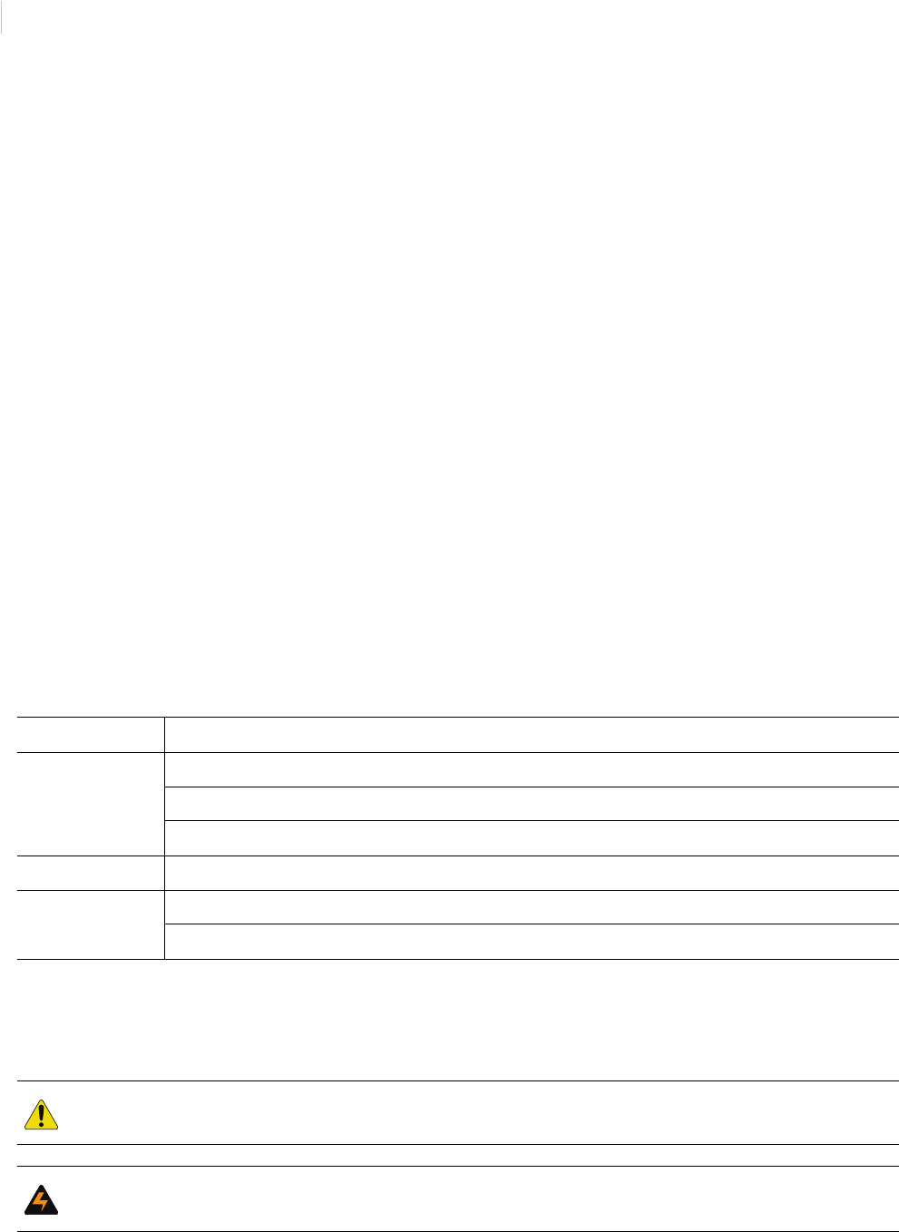
Topa z
User Manual
xviii
Radio frequency
This equipment generates, uses, and can radiate radio frequency energy and if not installed and
used in accordance with the instructions manual, may cause interference to radio communications. It
has been tested and found to comply with the limits for a Class A computing device pursuant to
Subpart J of Part 15 of FCC Rules, which are designed to provide reasonable protection against
such interference when operated in a commercial environment. Operation of this equipment in a
residential area is likely to cause interference; in which case the owners are required to take
whatever measures may be necessary to correct the interference at their own expense.
Note: Shielded interface cables are required with this equipment.
If problems arise
If your telephone equipment is not operating, immediately remove it from your telephone line, as it
may cause harm to the telephone network. If the telephone company notes a problem, they may
temporarily discontinue service. When practical, they will notify you in advance of this disconnection.
If advanced notice is not feasible, you will be notified as soon as possible. When you are notified,
you are given the opportunity to correct the problem and informed of your right to file a complaint with
the FCC. Contact your telephone company if you have questions about your phone line. If repairs are
needed on the ACU field panel, repairs should be performed by your authorized representative.
Conventions used in this document
The following conventions are used in this document:
Safety terms and symbols
These terms may appear in this manual:
Bold Menu items and buttons.
Italic Emphasis of an instruction or point; special terms.
File names, path names, windows, panes, tabs, fields, variables, and other GUI elements.
Titles of books and various documents.
Blue italic Hyperlinks to cross-references, related topics, and URL addresses.
Monospace Text that displays on the computer screen.
Programming or coding sequences.
CAUTION: Cautions identify conditions or practices that may result in damage to the equipment or other property.
WARNING: Warnings identify conditions or practices that could result in equipment damage or serious personal
injury.

This chapter provides an overview of the Topaz system as well as
information on installation and configuration.
In this chapter:
About the Topaz System. . . . . . . . . . . . . . . . . . . . . . . . . . . . . . . . 2
System Requirements . . . . . . . . . . . . . . . . . . . . . . . . . . . . . . . . . 3
System Options . . . . . . . . . . . . . . . . . . . . . . . . . . . . . . . . . . . . . . 3
Upgrading existing Topaz software. . . . . . . . . . . . . . . . . . . . . . . . 4
Software Installation . . . . . . . . . . . . . . . . . . . . . . . . . . . . . . . . . . . 8
Chapter 1 Getting Started

Topa z
User Manual
2
About the Topaz System
The Topaz System is a PC-based Facility Security System for access control, alarm monitoring,
interactive color graphics, photo badging, and CCTV (Closed Circuit TV) Control. The system uses
the Windows 2000 Professional, XP Professional, or Windows 7 operating system and employs the
use of an Internet browser interface technology along with a unique self-configuring software
package called Auto Configuration. This allows you to easily set up standard input devices. The
Topaz System integrates alarm monitoring, access control, and remote control capabilities
throughout a site.
Topaz consists of the file server computer, one (1) additional workstation, ACURT Intelligent
Controllers, card readers, alarm sensors, and door locking hardware. To communicate with card
readers, alarm points, and the workstation, the system uses Secure Communications Protocol (SCP)
through Dial-up, RS-232 / RS-485 hardwire connections, or TCP/IP on LAN / WAN networks.
The basic concept behind Topaz is a central monitoring system that can monitor or control
movement within a building or throughout multiple facilities. The system is modular and easily
customized to fit almost any building's security and access control needs for up to 64 readers and
2,000 cardholders.
All data entry is performed at a file server or workstation using a mouse and keyboard through the
Internet browser Interface.
The Topaz System continuously polls the remote panels; checking communication protocols, tamper
switches, alarm inputs, and cardholder access events. Events are displayed on workstation monitors
and logged to the PC.
The system performs three major functions:
• Facilitates communications between the server and remotely located control panels.
• Supervises and reports changes in the status of alarm and access devices that are
connected to the control panels. Changes are reported as alarms, troubles, or event
occurrences. Alarm devices are sensing devices such as motion detectors, door contacts,
temperature gauges, etc. Access devices are card readers, or keypads that control doorways
and other access locations like elevators and parking lot gates.
• Performs remote control activities. Remotely located devices are controlled through manual
operator commands, automatically according to events, or time schedules stored in the
computer.

Chapter 1
Getting Started
3
System Requirements
To use the Topaz software, your PC must meet the following minimum requirements:
• Pentium® 4 processor or equivalent.
• Processor speed: 1.8 GHz or Higher.
• Windows XP PRO (with Service Pack 1), 2000 Professional (with Service Pack 4), or
Windows 7
• Microsoft Internet Explorer 6.0 or above installed (the wizard must be completed), which must
be installed from the Topaz CD.
• 768 MB Random-Access Memory (RAM) on the server. 512 MB on the workstation
• SVGA display card with 1024 X 768 screen resolution, able to support 65K colors. If using
Windows XP or 2000 Professional set at High Color (16bit).
• Video Memory: 4 MB.
• Disk Drive Space Required: 2 GB. 100 MB for workstation
• CD ROM Drive: 20X.
• If using Photo Badging, a USB Camera can be used or the GE Video capture card Composite
Video Camera is required. For a list of compatible USB cameras, refer to the software CD.
• Serial RS-232 Ports are required if using direct communication to field panels.
• Parallel Ports: Optional for printer.
• USB Ports: 1 minimum is required for the Software Sentinel.
• A network card must be installed with static TCP/IP enabled. Static IP addresses are
required.
• Removable media recommended for back-up.
System Options
• Eltron P310-C Dye Sublimation Card Printer.
• Report and Logging Printer.
• Digital Video Capabilities using the GE DVMRe Triplex.
The above options can be obtained through your local independent distributor.
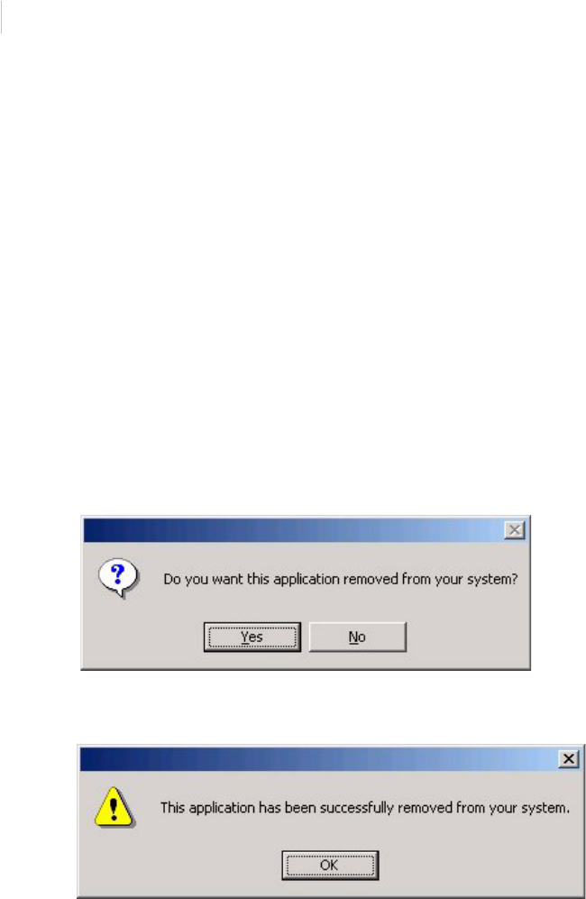
Topa z
User Manual
4
Upgrading Existing Topaz Software
Before performing an upgrade it is important to have a current backup of your existing database. We
also recommend that you have the media for the current version of your operating system and Topaz
software in the unlikely event you need to revert to this version temporarily.
Upgrading from Version 1.4.6
When upgrading from version 1.4.6, before installing the new version, you need to uninstall your
existing version of Topaz. No further user intervention is required.
To remove the existing installation, you may either use the Topaz 1.4.6 Installation CD or use your
Add/Remove Programs option in your desktop Control Panel as shown in the following steps:
1. Click the Start button on the lower left corner of the computer desk top and select Settings,
then Control Panel. When the Control Panel window opens, double-click the Add/Remove
Programs icon.
2. Select Topaz and click the Change/Remove button.
3. Click Yes to confirm the removal of the older version of Topaz. When the program has been
removed, the following message displays.
4. Click Ok.
5. Insert the Topaz installation CD and install the new version of Topaz, as described in the
section Software Installation on page 8.
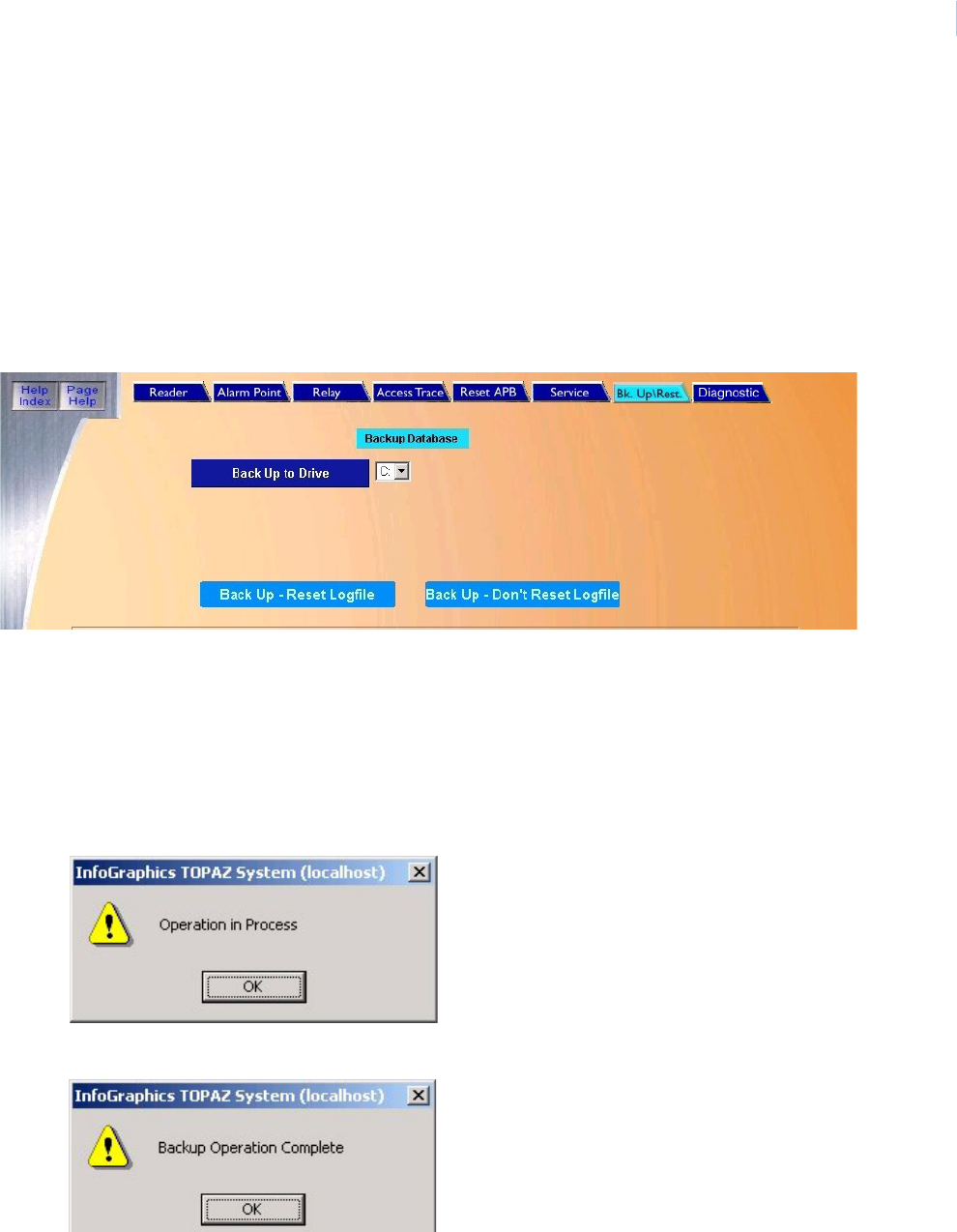
Chapter 1
Getting Started
5
Upgrading from Version 1.4.5 or earlier
Because versions before 1.4.6 used a different installer and a different default installation directory, it
is necessary to perform the following steps:
Note: Before starting Topaz make sure that “Microsoft Internet Explorer 6.0 provided by GE” has been installed using
the Topaz CD and the wizard has been run to complete the installation. If you have IE 6.0 already installed on your
computer, check if the title bar states “Microsoft Internet Explorer provided by GE”. If not, you must install the
Virtual Machine that is located on the CD. For more information, see Installing Virtual Machine on page 8.
1. Before installing the new software, perform a complete Backup of the system. Navigate to
the Control tab and select Back Up\Restore. The following page displays.
2. Select the Drive letter for the location where the files are to be backed up from the drop-
down list of available drives. (C: E: F: etc.).
3. After the selection has been made, click Back Up - Don’t Reset Logfile to start the backup
process.
Note: We recommend when you backup the system for an upgrade, that you do NOT reset the log. This allows the
current log to be imported into the new 1.4.7 version of Topaz making past events available.
A window displays Operation in Process, indicating that the backup has begun.
4. Click OK
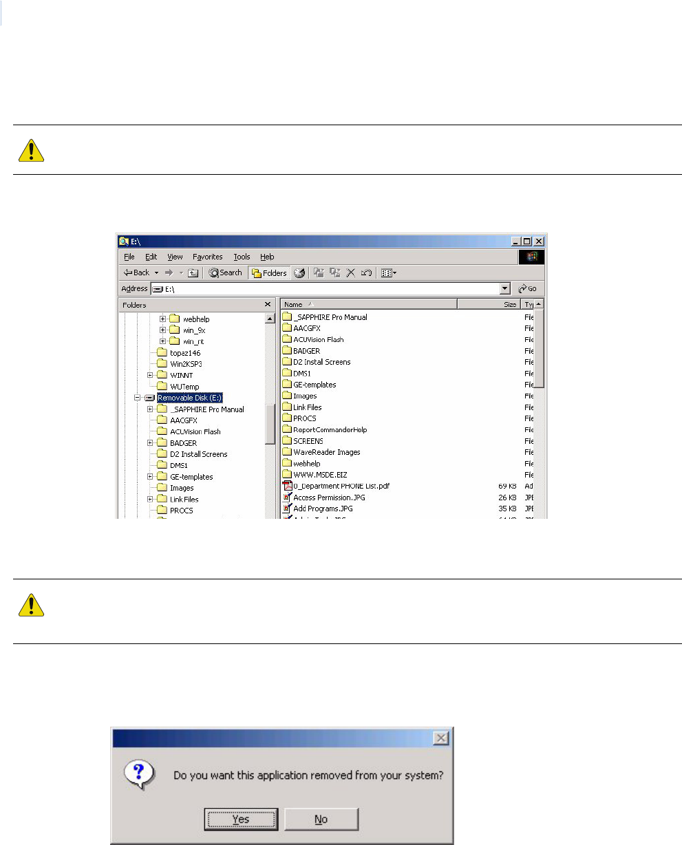
Topa z
User Manual
6
5. Once the backup is complete, the message “Backup Operation Complete” displays. Do not
log off or shut down Topaz until this message appears or the backup will be corrupted..
6. Shut down Topaz and double-click the My Computer icon and browse to the location where
the backup was stored.
7. There should be five new folders: AACGFX, BADGER, DMS1, PROCS, and SCREENS.
These folders contain the backup. Delete the SCREENS folder and close this window.
8. To uninstall your existing version of Topaz, click the Start button and select Settings, then
Control Panel. When the Control Panel opens, double-click Add/Remove Programs.
9. Select Topaz and click the Change/Remove button.
CAUTION: You must wait until the Backup Operation Complete dialog window displays before shutting down
Topaz. If you do not do this, the database will be corrupted and will not function.
CAUTION: You MUST delete the SCREENS folder. The SCREENS folder contains the old sysconfg.dat file. If this
folder is not deleted, when the database is imported into the updated version of Topaz, this older version will
overwrite the new sysconfg.dat and some features will not function.

Chapter 1
Getting Started
7
10. Click Yes to confirm the removal of the older version of Topaz. When the program has been
removed, the following message displays.
11. Click Ok.
12. Insert the Topaz installation CD and install the new version of Topaz, as described in
Software Installation on page 8.
13. When the installation is complete, open Windows explorer or My Computer and navigate to
the folder:
C:\Program Files\GE\Topaz\Screens
14. Locate the file, sysconfig.dat, and move it to a temporary folder.
15. There are now two Topaz icons on your desktop. One of them is labeled Topaz the other one
is Topaz Server. From your desktop, double-click Topaz Server (not Topaz).
16. Log on as master.
17. Navigate to the Control tab and select Back Up/Restore.
18. Under Restore Database, select the drive letter C.
19. After the restore is complete, shut down Topaz and restart the computer.
20. After the computer is rebooted, log on to Windows explorer and remove the Topaz directory
from the C drive that was created in step 3.
21. Navigate to the temporary folder where you placed the file, sysconfig.dat, in step 14 and
replace it in the folder: C:\Program Files\GE\Topaz\Screens
22. From your desktop, double-click Topaz (not Topaz Server). Log on to Topaz using your
installer login and password.

Topa z
User Manual
8
Software Installation
Before you Start Installing the Software
Note: Before starting Topaz make sure that “Microsoft Internet Explorer 6.0 provided by GE” has been installed using
the Topaz CD and the wizard has been run to complete the installation. If you have IE 6.0 already installed on your
computer, check if the title bar states “Microsoft Internet Explorer provided by GE”. If not, you must install the
Virtual Machine that is located on the CD. For more information see Installing Virtual Machine on page 8
Setup for Internet Explorer
1. From Window’s desktop, right-click the Internet Explorer Icon and select Properties. Do not
use a Short Cut Icon.
2. On the General tab, click Settings, select Every visit to the page, and click OK to save.
3. On the Connections tab, click LAN Settings and make sure Use a proxy server for your
LAN is NOT selected. If it is selected, we recommend you uncheck the box and click OK,
unless a proxy is required. If a proxy is required, leave Use a proxy server for your LAN
checked, click Advanced..., and add the address of the Topaz server in the exceptions box.
4. On the Privacy tab, move the slide bar to Low, then click OK to save. Topaz uses session
cookies (no information is written to disk), which may also be enabled using the Privacy tab,
and clicking Advanced...
5. Click OK to save and exit Internet Explorer Properties.
This topic describes how to begin interacting with the Topaz System Software. The installation uses
default options.
The Auto configuration function may also be used to assist you in setting up the system.
Whenever possible power-up the system's peripheral devices before activating the server computer.
In this way, any errors or diagnostic messages display at the system's monitor or printer.
Note: If you use a workstation, the server should be running on the network before starting up the workstation.
The installation steps for a Server or Workstation are almost identical but are described separately.
The installation steps for a Server are described below.
The System Software comes on a CD (Compact Disk). The CD is used to load the Topaz application
onto the computer server and workstation.
If you are using Windows 2000 or XP, log on as the Administrator.
Installing Virtual Machine
The installer for virtual machine is located on the Topaz software CD.
1. Insert the CD and when the Install window opens, select Browse CD.
2. When the folders window displays, click the folder named IE6 to open it.
3. Locate the msjavx86.exe file and double-click the file name. The following install window
displays.
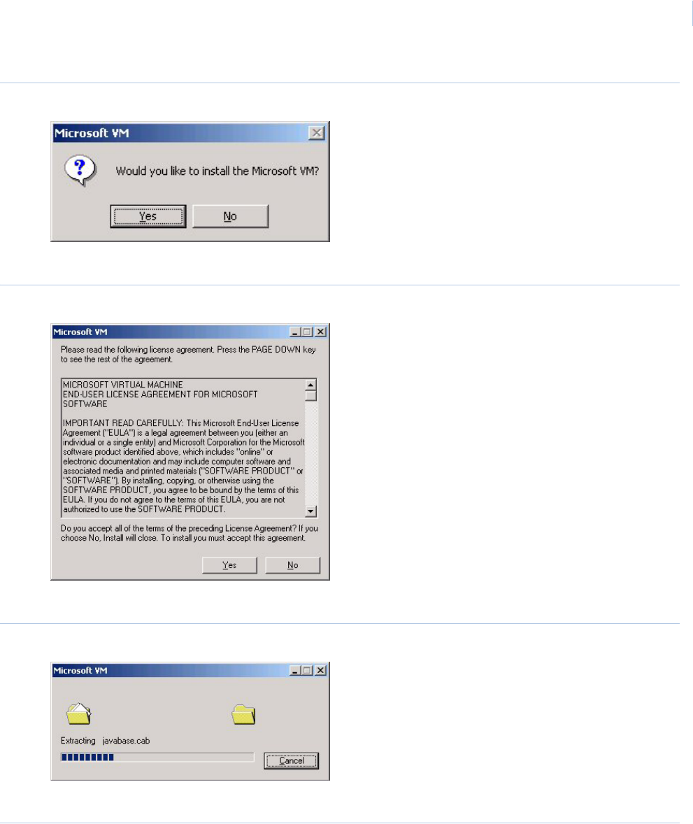
Chapter 1
Getting Started
9
Figure 1. Microsoft VM
4. Click Yes. You do want to install the Virtual Machine.
Figure 2. Microsoft VM License Agreement
5. Read the agreement and click Yes to begin the installation of the files.
Figure 3. Microsoft VM extracting
A progress bar shows the process of the installation.
Figure 4. Microsoft VM installation complete
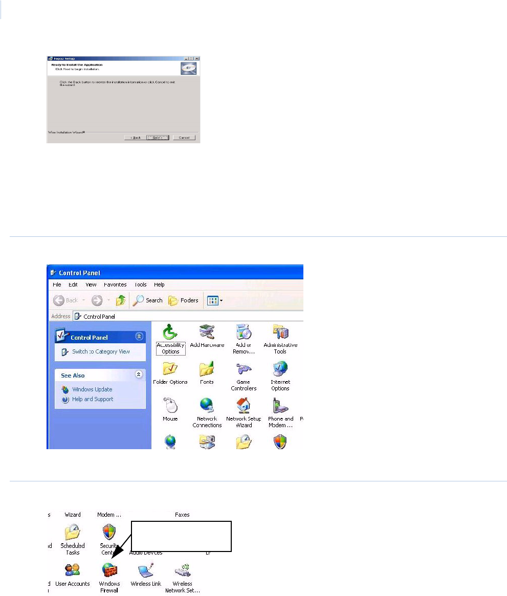
Topa z
User Manual
10
6. When “The installation is complete” message displays, click OK.
Setting XP sp2 Firewall
1. To open the Control Panel click Start > Settings > Control Panel
Figure 5. Control Panel
2. Double-click the Windows Firewall icon.
Figure 6. Windows Firewall
3. When Windows Firewall opens, click the Exceptions tab.
Click this icon to open
the Firewall controls
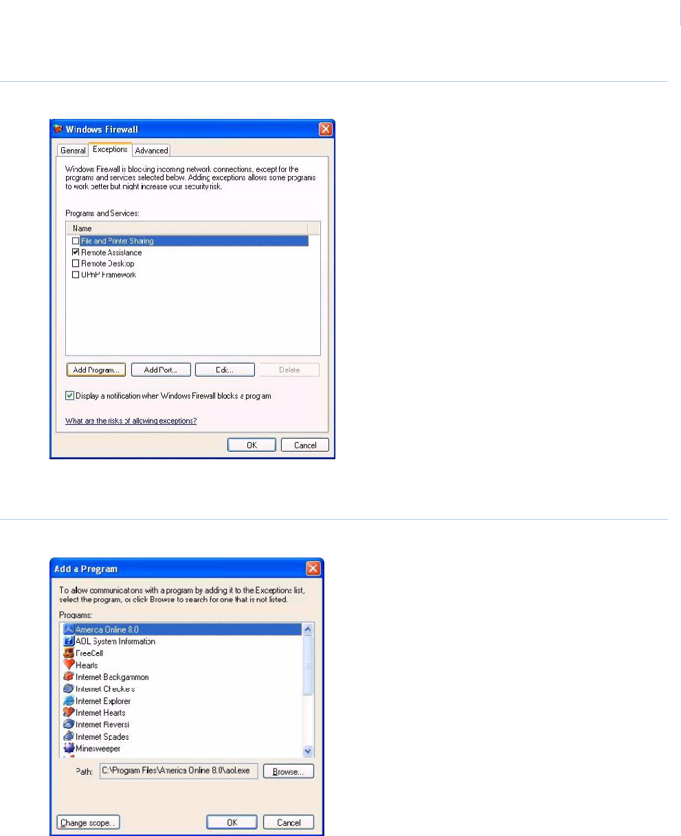
Chapter 1
Getting Started
11
Figure 7. Exceptions tab
4. Click Add Program to add two components of Topaz to the list of programs that may pass
through the Firewall.
Figure 8. Add Program
5. Using the Browse button, locate mp.exe. It is located in the folder where Topaz was
installed. The default location is C:\Program Files\GE\Topaz folder as shown below.
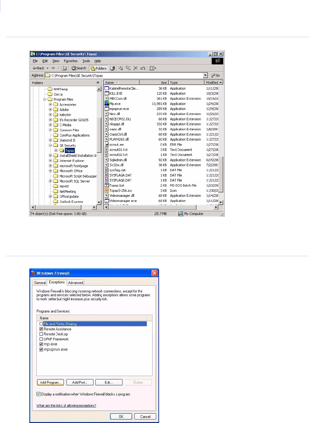
Topa z
User Manual
12
Figure 9. Default Topaz directory
6. Highlight mp.exe in the list and click Open to add it to the Add a Program window. Highlight
mp.exe in the Add a Program window and click OK.
7. Repeat steps 4. through 6. but this time add mpuprun.exe.
Figure 10.mpuprun.exe
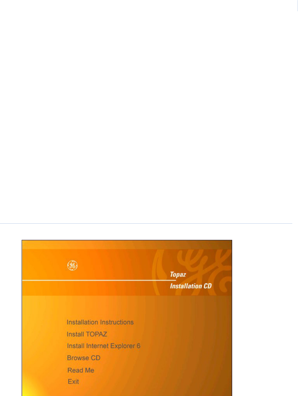
Chapter 1
Getting Started
13
8. The program now appears in the Programs and Services section of the Exceptions tab. Make
certain that the check box beside it contains a checkmark. Click OK to close the Firewall
properties.
Installing a Host PC Server
Note: The installation steps for a server are described below. The installation steps for a Workstation are described
under “Hardware”, then “Workstation”, and then “Add a Workstation” elsewhere in this manual.
Make sure you are logged in as the Administrator so you have the correct rights to install software.
Insert the Topaz Installation CD into the CD drive. If Auto Insert Notification is enabled for your CD
drive, the Install Menu provides a list as shown below.
If the Install Menu does not appear within one minute, follow this procedure:
1. Open Windows Explorer.
2. Double-click the drive letter for the CD drive.
3. In the root directory, double-click the file start.bat.
The Topaz Install screen displays.
Note: Before installing Topaz make sure that “Microsoft Internet Explorer 6.0 provided by GE” has been installed
using the Topaz CD and the wizard has been run to complete the installation. If you have IE 6.0 already installed
on your computer check if the title bar states “Microsoft Internet Explorer provided by GE”. If not, you must install
the Virtual Machine that is located on the CD. For more information see Installing Virtual Machine on page 8
Figure 11.Topaz Installation CD
1. Click Install Topaz to start the installation setup.
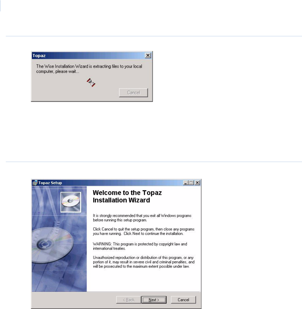
Topa z
User Manual
14
Figure 12.Topaz files extracting
2. If this is the first time Topaz has been installed on your computer and the Microsoft .NET
Framework is not installed, the Wise Installation Wizard dialog window shown above
displays. Extracting and installing the .NET framework may take several minutes. Please wait
while the Hourglass progress icon rotates. When the framework is completed, the Topaz
Installation Wizard begins. If the .NET framework is already installed on your machine, it
proceeds directly to the Welcome to the Topaz Installation Wizard dialog window.
Figure 13.Topaz Setup: Installation Wizard
3. Click Next to continue.
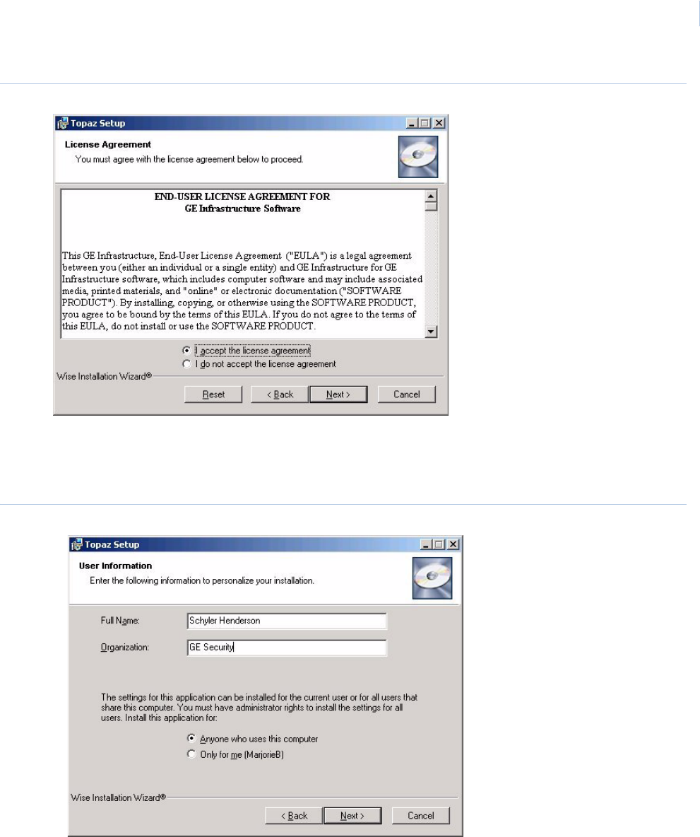
Chapter 1
Getting Started
15
Figure 14.Topaz Setup: License Agreement
The next window is the End User License Agreement. Read it then select I accept the
license agreement. The Next button becomes available once the agreement is accepted.
Click Next to continue.
Figure 15.Topaz Setup: User Information
4. The next window asks you to enter User Information. Type the name of the user in to the
Full Name field and the name of the organization into the Organization field. Select the radio
button beside Anyone who uses this computer. This is used to permit the system to
communicate with and respond to the Video Recorder. Click Next to continue.
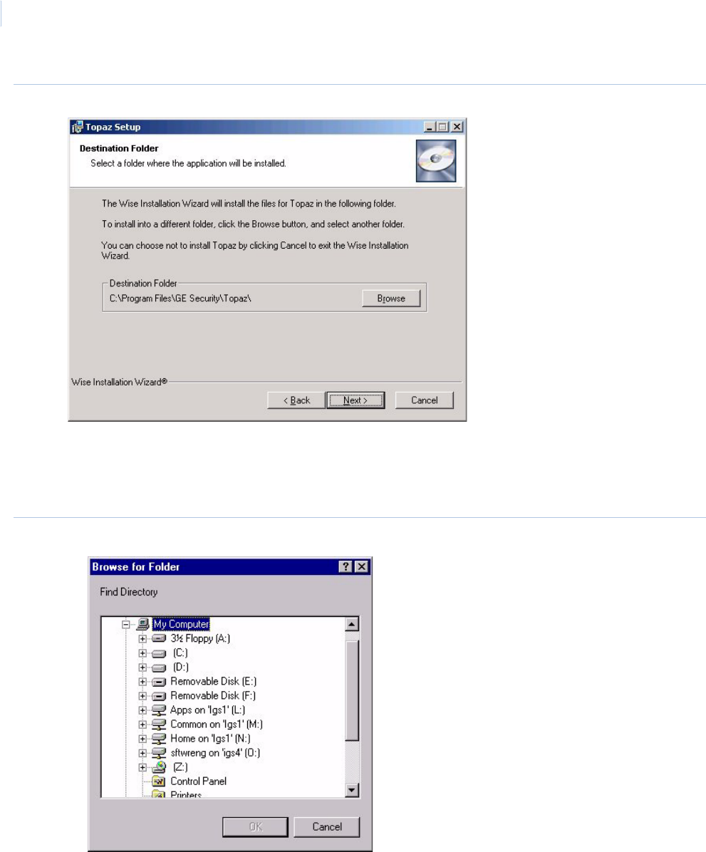
Topa z
User Manual
16
Figure 16.Topaz Setup: Destination Folder
This dialog window determines were the Topaz files are stored on the system. If you do
not want to use the default directory, you may follow this procedure:
a. Click the Browse button and the Browse for Folder window displays.
Figure 17.Browse for Folder
b. If you prefer to use a different directory, such as “Program Files”, select the desired
location for the Topaz software (such as c:\Program Files\Topaz) and click OK, then Next.
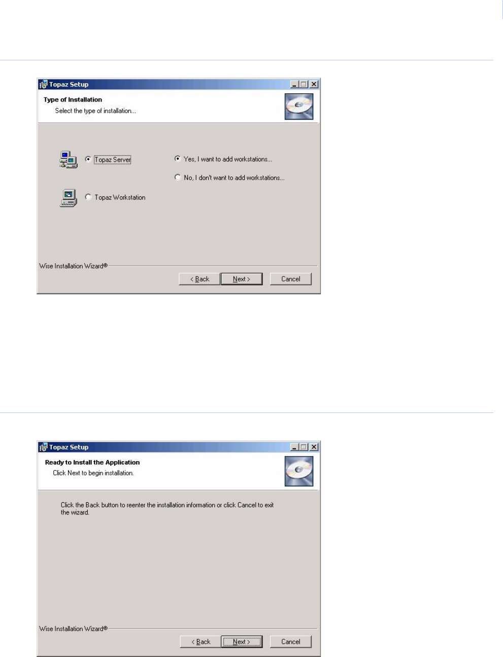
Chapter 1
Getting Started
17
Figure 18.Topaz Setup: Type of Installation
5. This dialog window determines the type of installation. Are you installing the Server? Click the
radio button next to Topaz Server. Also consider whether remote workstations (those not
resident on the server computer itself) are used. If other computers are used as workstations,
click the radio button next to Yes, I want to add workstations. If you are installing a
workstation, select Topaz Workstation. For more information see How to install a workstation
on page 207.
Note: You must install Topaz on the server computer before installing it on any workstation computer.
Figure 19.Topaz Setup: Ready to Install the Application
6. If you satisfied with your settings, click Next to start installing the system.
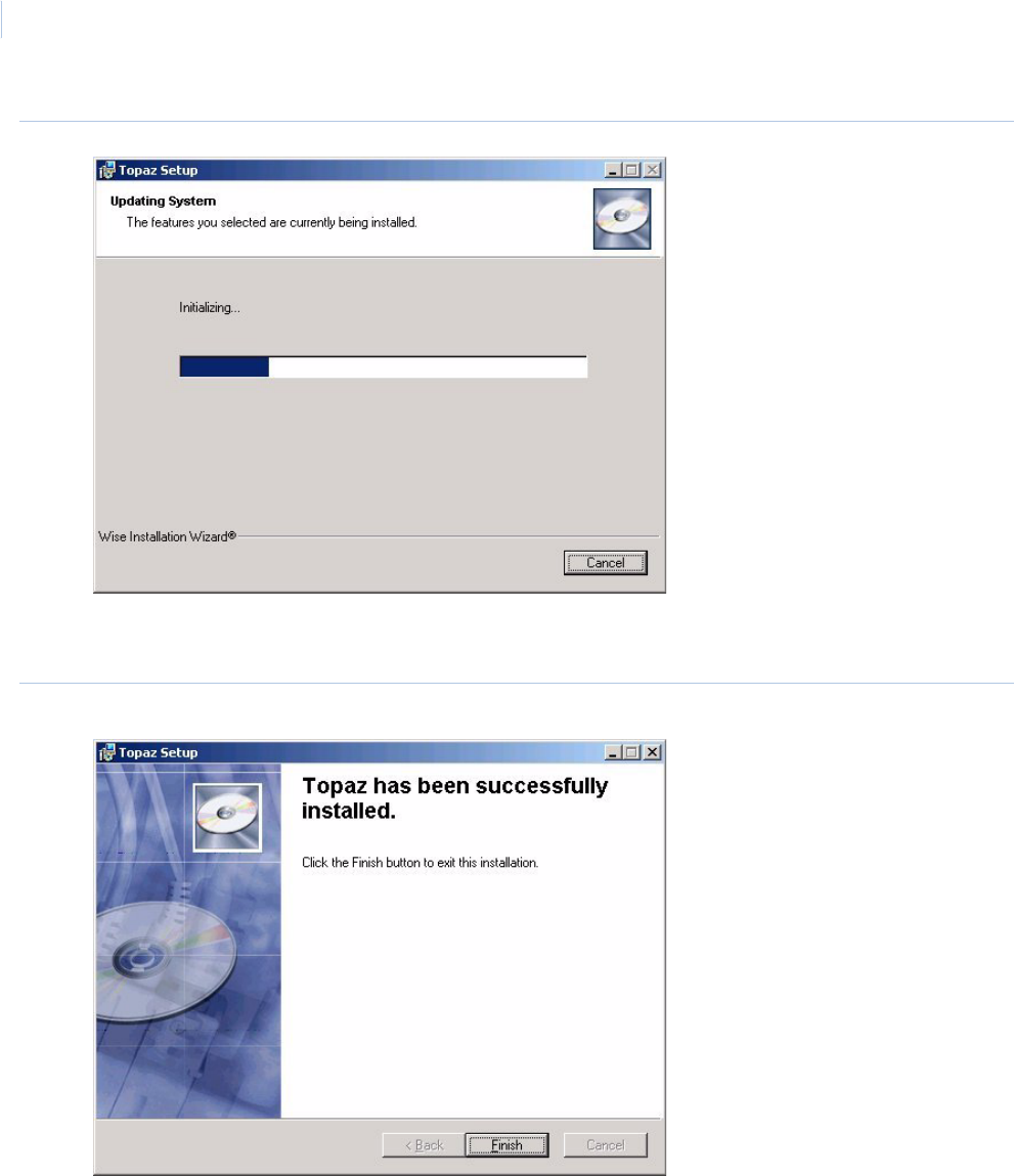
Topa z
User Manual
18
Figure 20.Topaz Setup: Updating System
The wizard uploads the required files and installs them onto the computer. During the
process, a progress bar displays.
Figure 21.Topaz Setup: Finish
7. When all files have been installed, the Topaz has been successfully installed dialog
window displays. Click Finish to continue with the installation of several video files. These
files are installed whether or not you are using Video.
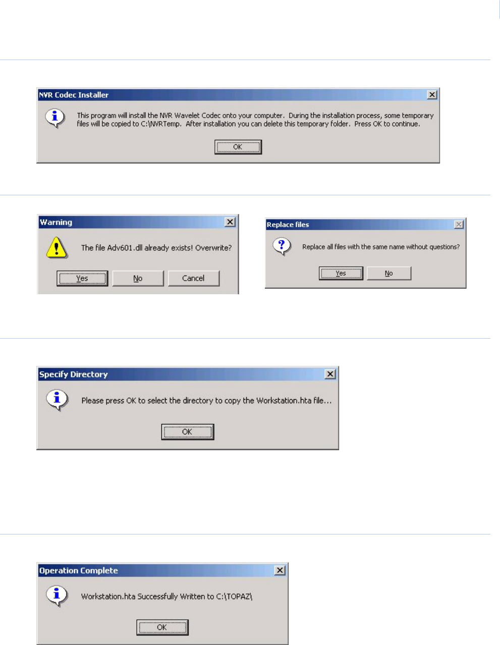
Chapter 1
Getting Started
19
Figure 22.NVR Codec Installer
8. Click OK to install the Video files.
Figure 23.Warning
Note: If a warning window displays that certain files already exist, click Yes to continue. When the dialog window asks
whether to replace all files with the same name without questions, click Yes.
Figure 24.Specify Directory
9. This dialog window appears if you selected Yes, I want to add workstations in step 5. Click
OK and another Browse window appears. Select where the Workstation.hta file should be
saved. This file is used when installing a workstation on another computer. Make certain that
the location selected is accessible by the workstation computers. After selecting the location
click OK.
Figure 25.Operation Complete
10. The dialog window indicates that the file was written successfully. Now wait a few seconds
and the Sentinel Driver installation wizard starts.
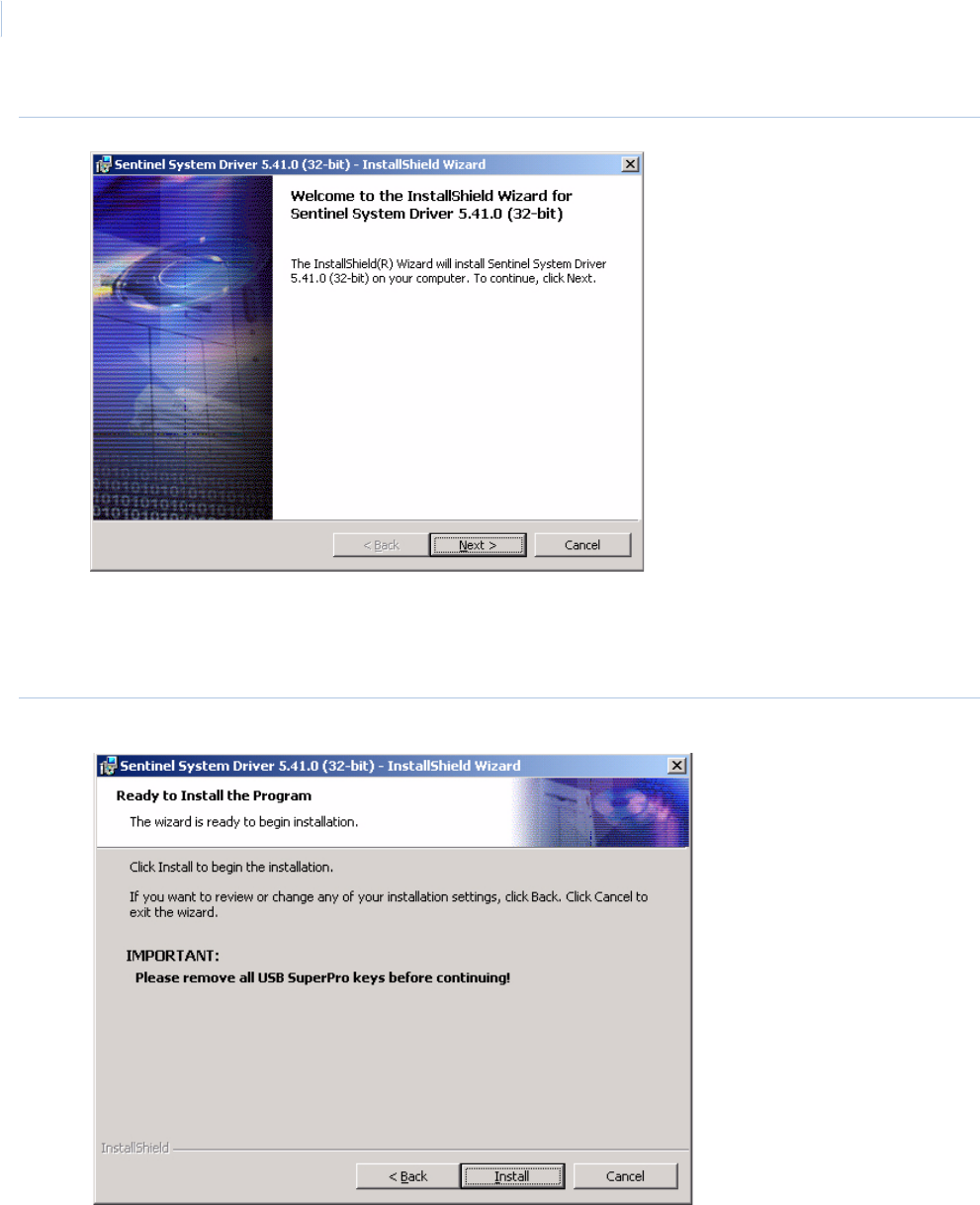
Topa z
User Manual
20
Figure 26.Sentinel System Driver: Welcome
Note: If this is the first time you have installed Topaz on this computer, you should follow the remaining steps. If this is an
update, you may cancel out of the Sentinel Driver wizard.
11. Click Next to install the sentinel drivers.
Figure 27.Sentinel System Driver: Ready to Install
12. Remove all software sentinel keys from the USB port before continuing. Click Install to
continue.
Note: The USB software sentinel key is provided with the Topaz system when you order it. This dongle is required for
Topaz to work properly. If this is an upgrade, you may have a serial sentinel key. This will work and does not need
to be replaced with a USB dongle. It also does not need to be removed during this process.
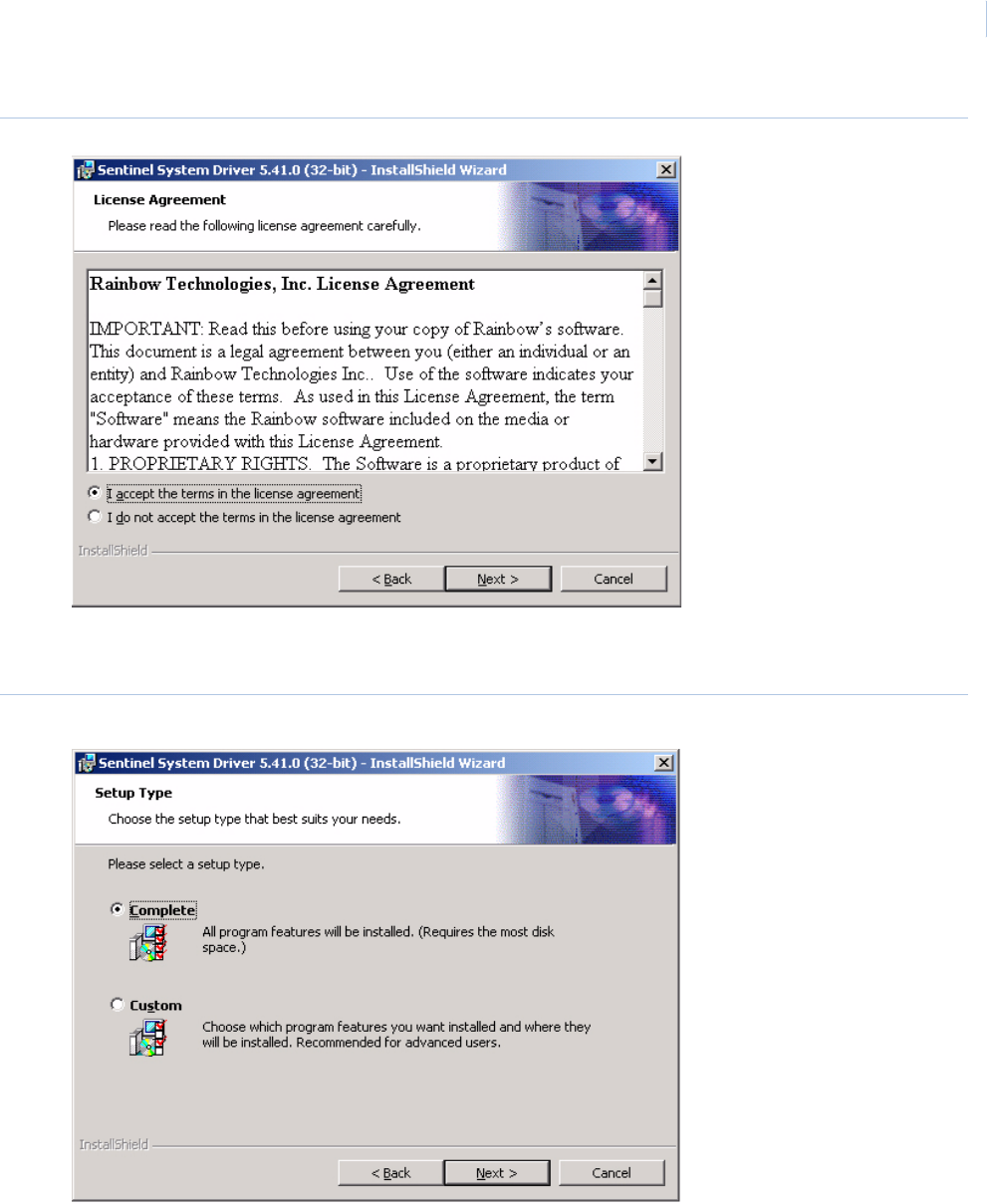
Chapter 1
Getting Started
21
Figure 28.Sentinel System Driver: License Agreement
13. Select I accept the terms in the license agreement, and the Next button becomes
available. Click Next to continue.
Figure 29.Sentinel System Driver: Setup Type
14. Select Complete, then Click Next to continue.
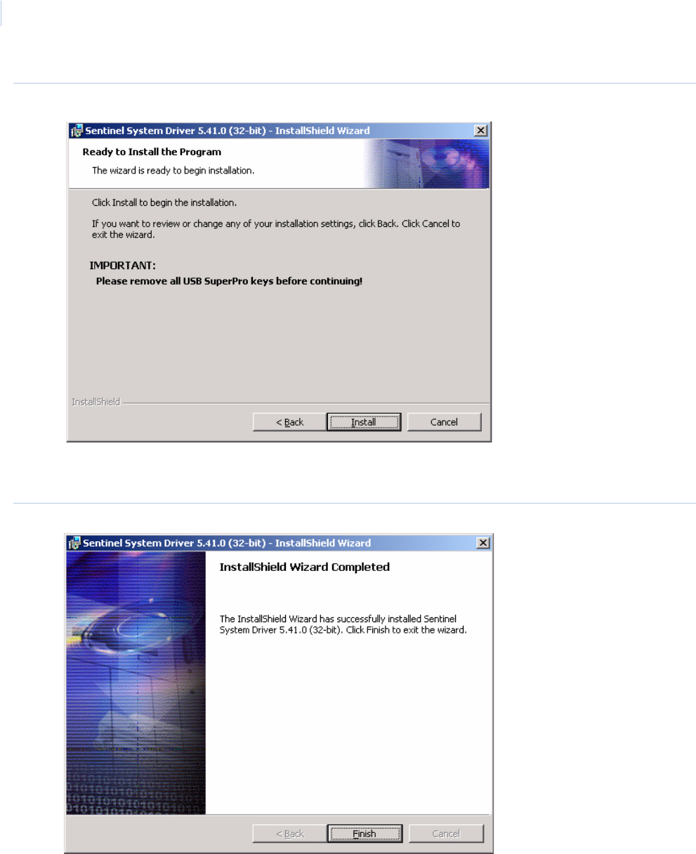
Topa z
User Manual
22
Figure 30.Sentinel System Driver: Ready to Install
15. Remove USB sentinel keys before continuing, then Click Install. A screen with a progress
bar displays while the Sentinel Driver files are installed.
Figure 31.Sentinel System Driver: Install Completed
16. Click Finish.
17. You are now returned to the desktop and the following message displays.
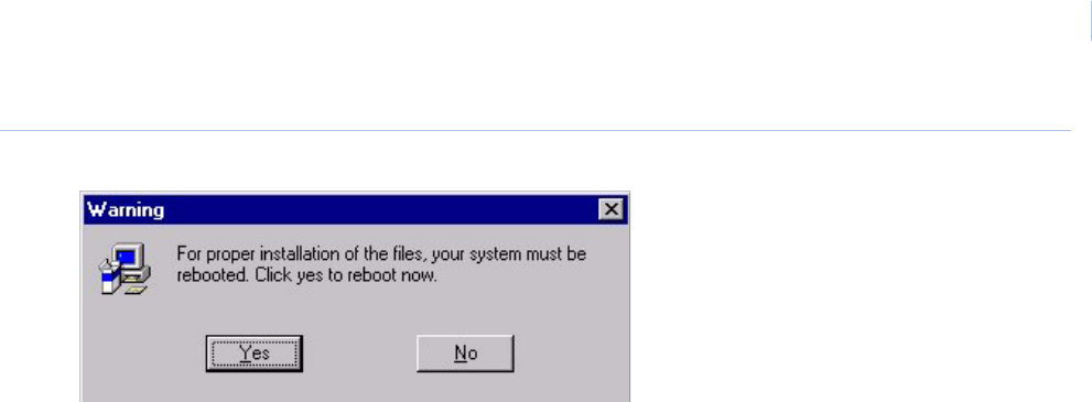
Chapter 1
Getting Started
23
Figure 32.Warning
18. You must restart your PC for the Topaz software to be activated. Click Yes to reboot your
system.
This ends the installation steps for a server. To add a workstation, see Workstation Page on
page 204.
To start Topaz, double-click the Topaz icon on your desktop.

Topa z
User Manual
24

This chapter describes how to begin using the Topaz system software. The
installation uses default options so you do not have to make decisions or
selections.
In this chapter:
Start Up. . . . . . . . . . . . . . . . . . . . . . . . . . . . . . . . . . . . . . . . . . . . 26
Help . . . . . . . . . . . . . . . . . . . . . . . . . . . . . . . . . . . . . . . . . . . . . . 26
Startup, Log-on, & Navigating. . . . . . . . . . . . . . . . . . . . . . . . . . . 28
Chapter 2 Using Topaz
Topa z
User Manual
26
Start Up
Note: Before starting Topaz, make sure Internet Explorer 6.0 or later was installed from the Topaz CD and the wizard
was run to complete the installation of IE, or Topaz will not operate properly.
The Auto configuration function may also be used to assist you in setting up the system.
Whenever possible, power-up the system's peripheral devices (field panels, readers, etc.) before
activating the server computer. In this way, any errors or diagnostic messages display at the
system's monitor or printer.
Note: If you use a workstation, the server should be running on the network before starting up the workstation.
Help
A major feature of Topaz is its Help section. Help is designed to assist you in real time on any part of
Topaz operations. This enhancement reduces your need to refer to written documentation and
reduces training time for new users.
Two Help buttons are located in the top left corner of each of the browser pages.
•Help Index - This button opens a content sub-window that enables you to locate topics from
the whole Help system by using the Table of Contents, Index, or Search functions.
•Page Help - This button opens a content sub-window that enables you to easily locate topics
covered on the currently selected browser window only. However, while using the Page Help
you may also click the Word SHOW button in the top left corner of the help page. This opens
the Global Help as a sub-window on the left side of the help page allowing you to access all
Help topics.
Navigating the Help Table of Contents
The Table of Contents structure follows the navigation hierarchy of Topaz. On the left side, the Table
of Contents displays.
Each closed book represents a branch of the tree, such as .
When you move the pointer over a book title, it underlines the Title. Clicking on the underlined title to
the right of the Book, opens that Book to display Pages (such as Cardholder Database Reports) in
the Book, and possibly more Books, as shown below:
You can click a Page, such as Recall All Events to go to the Recall All Events
Help page, as shown below:
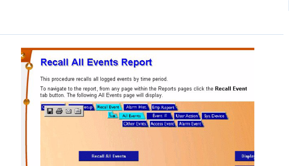
Chapter 2
Using Topaz
27
Figure 33.Sample Help page

Topa z
User Manual
28
Startup, Log-on, & Navigating
Startup
After the Topaz software has been properly installed, double-click the Topaz icon on the Windows
desktop to startup the Topaz program.
After a brief initialization period, the log-on window shown below appears on your computer screen.
Log-on Window
Following the System initialization, the Workstation Log-on Window fills the monitor.
Figure 34.Workstation Log on window
To log-on to Topaz, place the mouse pointer in the box labeled Operator ID, click, and type your
Operator ID. Then move the pointer to the box labeled Password. Click and type your password.
Note: If this is a new system you may use the default Operator ID of “master” with no password. Neither the Operator ID
nor the Password is case sensitive. You may change the default password by following the procedures in the
section Operators Setup Page on page 161.
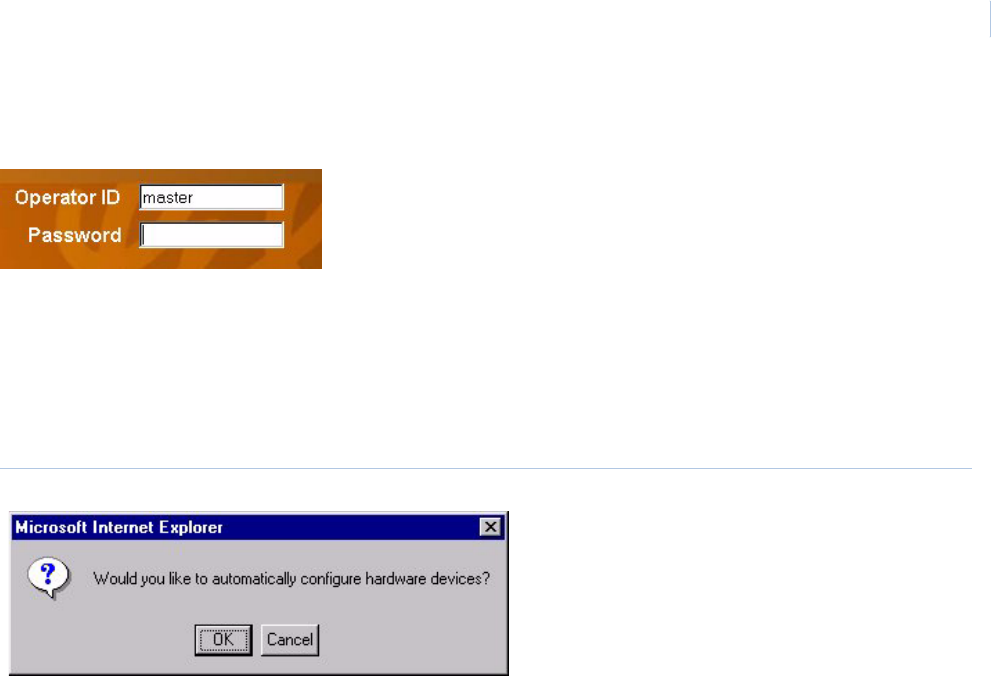
Chapter 2
Using Topaz
29
Now, click Enter to complete your log-on to the Topaz System.
Starting Topaz the First Time Topaz is Started
The following applies only if you are using the Topaz Software for the first time. If this is not the first
time, and you wish to use Auto Configuration, see Auto Configuration Setup Page on page 252.
After clicking Enter, the following message displays.
Figure 35.Auto configuration
To have Topaz automatically configure the software and hardware, click OK. For more details see
Topaz Quick Start on page 30 and Auto Configuration on page 31.
If you do not wish to auto configure your system, click Cancel and the standard workstation browser
navigation page displays as shown in Server/Workstation Display on page 35.
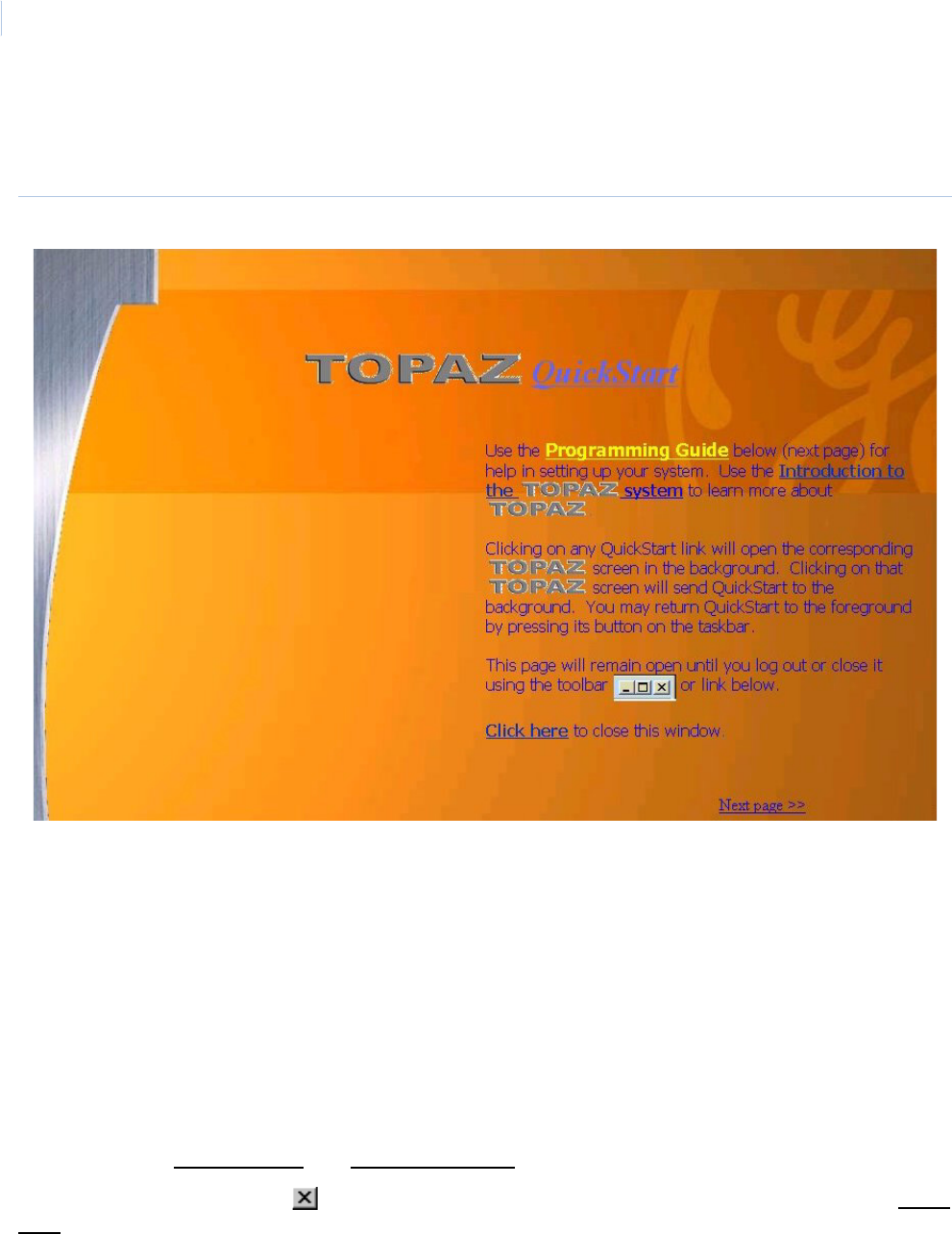
Topa z
User Manual
30
Topaz Quick Start
When you startup Topaz, the QuickStart displays as shown below.
Figure 36.Topaz QuickStart
QuickStart consists of seven (7) pages of information on the Topaz System and how to get it set up
easily and quickly.
QuickStart stays active in the foreground even if you click a button to access a Topaz screen. To see
more of the background Topaz screen, click and drag the QuickStart page by the menu bar (at the
top). You may also “minimize” QuickStart by clicking on its minimize button in the upper right corner
of the QuickStart window, or click anywhere outside of the QuickStart window. Once minimized, you
can open QuickStart at any time by clicking on the QuickStart button in the Navigation Bar in the left
side of the main Topaz window.
You can navigate through QuickStart by:
• Click the underlined links.
• Use the scrollbar on the right of the window.
• Click the Next Page >> and << Previous page links.
To close QuickStart, click the in the upper right corner of the QuickStart window or click the Click
here link.
You can open QuickStart at any time by clicking on the QuickStart button in the Navigation Bar in the
left side of the main Topaz window.

Chapter 2
Using Topaz
31
All Topaz buttons in the QuickStart may also be clicked to access that part of the Topaz software.
Subjects covered in the QuickStart are:
• Programming Guide
• Auto Configuration
• Batch Card Entry
• Suggested System Setup Flow Chart
•Setup
• Hardware
• Cards
• Other menus you should become familiar with
• An Introduction to the Topaz Access Control System
Auto Configuration
Auto Configuration is a unique software feature that automates the systems setup of hardware and
cardholder programming efforts. All the installer or end-user needs to do is log-on, and Topaz
automatically detects and defines all field devices connected to each port on the computer. Topaz
also defines a default value for all device, system and cardholder data. Such pre-defined and pre-
configured data includes the creation of basic reader access groups, time intervals, time schedule,
holidays, activation date, cardholder access group assignment, reader, alarm point defaults, default
alarm definitions, and alarm message text, as well as the physical hardware hierarchy and its
graphical “tree” representation.
The Topaz software initiates polling on demand by user command as described below, of the file
server's maximum five (5) serial communication ports and one (1) LAN port. It records an inventory
of all port communication interfaces (that is, serial card, modem, LAN card, and CCTV switcher) and
all their downstream “devices” (for example, ACUs, Readers, Alarm Points, Relay Outputs, System
Alarms [device off-line, tamper, battery low], Workstation, and CCTV Switch).
Initiation of the Auto Configuration Feature
You can start Auto Configuration by either of the following ways:
• If this is a new Topaz installation, without any communication ports or hardware devices
configured, and you click the Topaz desktop icon to start Topaz, and then enter your log-on id
and password, Auto Configuration starts automatically. You must have the proper password,
since access to Auto Configuration is password protected.
Note: You must start Topaz from the desktop icon. Logging off and logging back on again does not start Auto
Configuration.
If you are using dialup or a LAN connection, some manual configuration is required, such as the LAN IP address,
or phone number.
Once you configure a port or device, Auto Configuration no longer starts automatically.
However, you can still run Auto Configuration manually by the next method.
• If you are running Topaz and have the appropriate permissions, you can click the Hardware
button on the left and then the Auto Configuration button on the menu on the right.
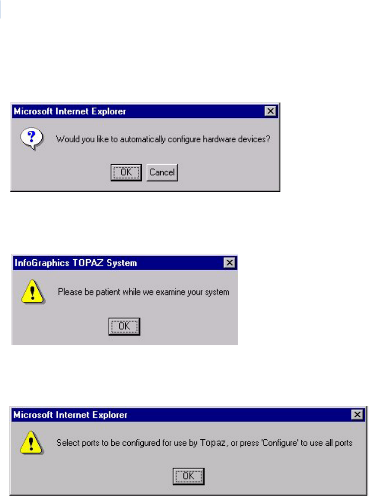
Topa z
User Manual
32
An Auto Configuration sequence may also be initiated from the Auto Configuration Home screen for
any or all selected devices listed in both the “Configured” and “Not Found” boxes.
Starting Auto Configuration displays the following dialog box:
If you select Cancel, you may continue with manual programming of the system. If you select OK,
the following message displays along with an hourglass in place of the mouse pointer:
Click OK to continue.
Topaz starts the Auto Configuration process to detect and configure the hardware. The process may
take a few minutes. If you have COM ports, the following message displays:
Click OK to continue.
You may click to select one or more ports you wish to Auto Configure. You may de-select highlighted
ports by clicking the Clear button or you may leave this page without further changes being recorded
by clicking on any of the buttons in the main tool bar on the left side of the screen.
Once you have selected the ports, press the Configure button, the system performs an automatic
configuration to find new devices or changes to the system on those highlighted ports.
The message “Operation Complete” displays. Click OK to continue.
The left side of the screen displays devices that have been either: (1) detected as physically
connected to the server, but have not been programmed/configured or, (2) they have been
programmed but are currently not connected.
The Auto Configuration Home screen displays the entire network of field devices: found-and-
configured, found-and-not-configured, and configured-but-not-found. On the right side of the screen,
all devices are displayed in a dynamic “Tree” formation, with Graphical Icon representations of the
Chapter 2
Using Topaz
33
various device types (for example, workstation, ACU, reader, alarm point, CCTV switch, and relay
output), and with the following text description colors:
The following is an example of what an Auto Configuration screen might look like:
Figure 37.Sample Auto Configuration screen
Found - not Configured Green
Connected - not Found Red
Found and Configured Black
Topa z
User Manual
34
Default Device Names
After Auto Configuration has been completed, the devices have numeric names, for example,
Reader 2-1-3 is Host Port two (2), Field Panel address one (1), Reader number three (3). You may
want to rename the devices with your own descriptive names. For more detailed information see the
chart below.
For more details on Auto Configuration see Auto Configuration Setup Page on page 252.
Note: Aside from auto configuring your system and specifically for day-to-day system hardware navigation and editing,
Topaz incorporates a separate device tree page. At any time you can click the Device Tree button in the main tool
bar to navigate to the stand-alone device tree.
Device Tree
The Device Tree is a dynamic “Tree” representation of the entire system’s hardware, from the
server’s communication ports, to all field hardware including workstation field panels (ACURT2/RT4).
Table 1. Default Device Names
Example Type COM # ACU Polling # Reader/Alarm# Alarm Type
Field Panel Device 1-0 Device 1 0
Reader RDR 1-0-0 RDR 1 0 0
Reader Alarm RDR 1-0-0 FO RDR 1 0 0 FO (Forced Open)
Alarm Alarm 1-0-0 Alarm 1 0 0
Area Area 1-0-0 Area 1 0 0
Example Type Device # Remote Module Port # Address Alarm Type
Panel Alarms ACU 1 -TAMPER ACU 1 TAMPER
Input Module RIM 1-1-7-OL RIM 1 1 7 OL (Offline)
Output Module RRM 1-1-5-OL RRM 1 1 5 OL (Offline)
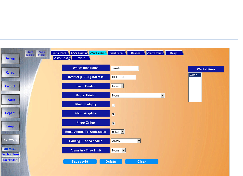
Topa z
User Manual
36
System Navigation Menu
Topaz’s Main Navigation Menu is on the left side of the main
Operator Screen. Use the mouse pointer to click the icons or
buttons to navigate through the system. The main navigation
buttons on the left of the Operator Screen and the Alarm Queue
window at the bottom of the screen are available at all times
while any page of the Topaz software displays.
The Alt Menu button displays the System Navigation Menu in a
multiple level (tree) format. See Alt Menu on page 37.
The Device Tree button displays the device tree at any time.
See Device Tree on page 257.
The Quick Start button calls up the quick start page to give you
a short overview of the system. See Topaz Quick Start on
page 30.
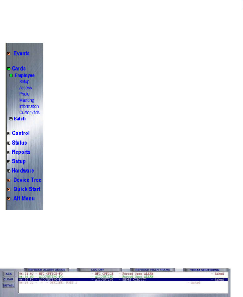
Chapter 2
Using Topaz
37
Alt Menu
Click the Alt Menu button to view the System Navigation Menu in a multiple level (tree) format.
Press the ‘+’ button to expand the branch you want to view. Then, click on the page name (for
example, ‘Photo’) to bring up the ‘Employee Card Photo’ page in the main portion of the window.
Click on the ‘-’ button to collapse a branch of the menu. Selecting another branch's ‘+’ sign also
collapses a viewed branch.
Alarm Queue Window
The Alarm Queue window at the bottom of the main Operator Screen is shown below.
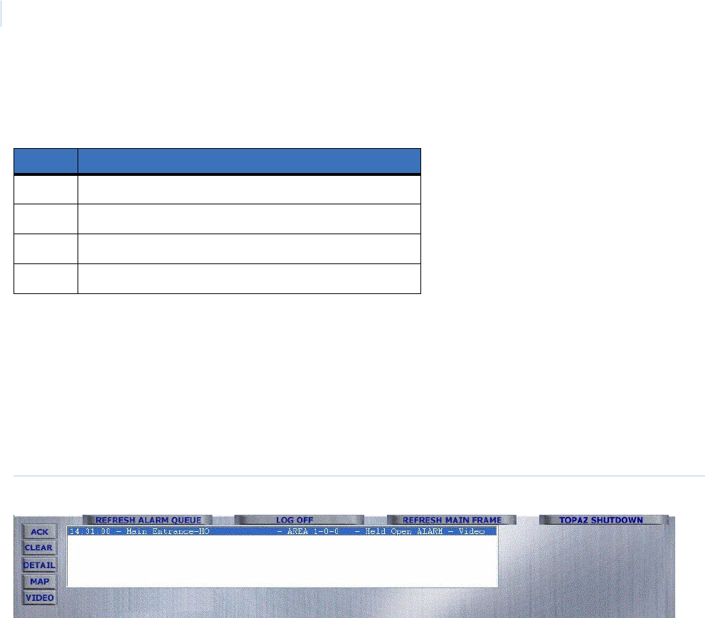
Topa z
User Manual
38
The Alarm Queue window displays alarms as they occur in RED. The color of the text for the alarm
shows its status. The table below defines the meaning of the colors.
If there are currently more events in the queue than can be shown in the window at one time, a
scrollbar appears at the right side of the window. The scrollbar allows you to scroll through all alarm
events in the queue.
To remove an alarm from the queue, you must first acknowledge it and then clear it, as described
below.
If you have the Video Option, the alarm event has the word video in the information text. When you
select an alarm with video, the Video button becomes available to the left of the queue.
Figure 39.Alarm Queue window
When an alarm is activated, video is recorded and the clip is linked to that alarm event. As long as
the alarm point remains active, this is the only video clip that is linked to that alarm event. If the alarm
point is secured but has not been cleared from the queue, and an second event activates the same
alarm point, the new alarm event produces a new video clip of the second triggering event. However,
if the alarm has not been cleared from the Alarm Queue, the only video that can be viewed from the
alarm queue is the first video associated with that alarm point. The later video clips have to be
accessed from the Event Queue. See Video Option on page 49
For any alarm in the queue that is linked to the Color Graphics MAP feature, you can triple-click that
alarm or click MAP to bring up the Color Graphics map assigned to it. For more details on Color
Graphics, see Color Graphics Maps on page 295.
Acknowledging an Alarm Event
To acknowledge an Alarm event, click the text of the alarm to be acknowledged so it is highlighted.
Click ACK and the Alarm Details page shown below displays. The alarm sound continues until all
alarms in the queue have been acknowledged.
Table 2. Alarm Queue window colors
Color Status
Red Device in alarm
Green Secure
Orange An access event, for example, access denied
Purple Trouble condition (short circuit, circuit fault, etc.)
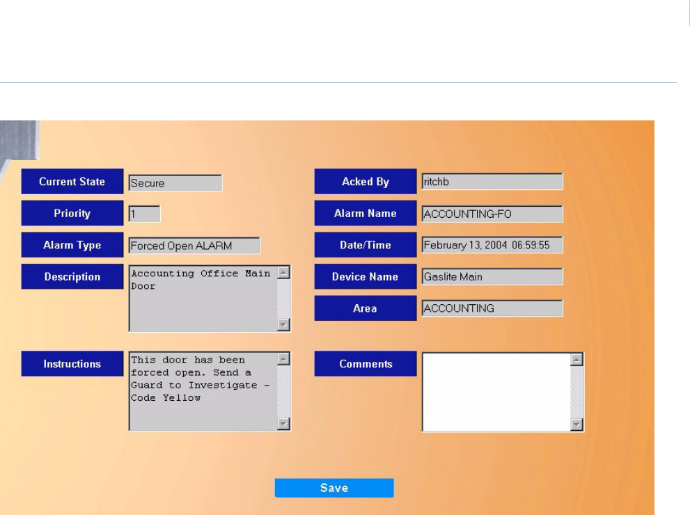
Chapter 2
Using Topaz
39
Figure 40.Alarm Details
The Alarm Details page contains the following information.
Click ACK to acknowledge the alarm. The name of the operator currently logged on to the system is
recorded in the Acked By field.
Note: The only field on the Alarm Detail page that can be changed or entered at anytime is Comments.
To close the Alarm Details window, click the X in the upper right corner of the window.
Current State The state of the alarm.
Priority The priority assigned to the alarm during alarm point setup.
Alarm Type The alarm type assigned to the alarm during alarm point setup.
Description The description assigned to the alarm during alarm point setup.
Instructions The instruction message text assigned during Alarm Option Instructions setup.
Acked By The name of the operator logged on to the system when the event was
acknowledged.
Alarm Name The name assigned to the alarm during alarm point setup.
Date/Time The date and time the alarm event occurred.
Device Name The name assigned to ACU field panel the point is attached to.
Area The area assigned to the alarm during alarm point setup.
Comments Comments typed in by the operator (optional).
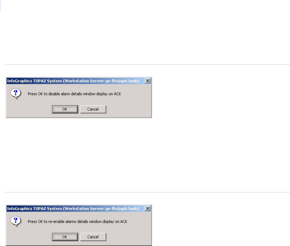
Topa z
User Manual
40
Alarm Details Page Auto Display
To stop the Alarm Details page from automatically displaying, right-click anywhere inside the alarm
queue window and the following message displays.
Figure 41.Disable alarm details window
Click OK to stop the auto display feature.
Each time you now acknowledge an alarm, the color of the text changes to indicate that the alarm
has been acknowledged, but the alarm details page is not displayed.
You can still call up the Alarm Details page by clicking Detail or by double-clicking on the text of the
alarm inside the alarm queue window.
To start the Alarm Details page automatic display again, right-click anywhere inside the alarm queue
window and the following message displays.
Figure 42.Enable alarm details window
Click OK and the Alarm Details page again automatically displays each time you acknowledge an
alarm.
Color Graphics Not Ready Message
If you click MAP or triple-click an alarm in the Alarm Queue Window, which is linked to Color
Graphics, the Color Graphics map is displayed. For more details on Color Graphics, see Color
Graphics Maps on page 295.
If you do not see a MAP button, Color Graphics has not been configured for the workstation. To
enable Color Graphics:
1. Click Hardware on the left side of the main screen.
2. Select Workstation.
3. Under Workstation, select the name of your workstation. The name should appear in the
Workstation Name field.
4. Select Alarm Graphics by clicking in the check box.
5. Click Save/Add.
6. Click Refresh Alarm Queue to show the MAP button.
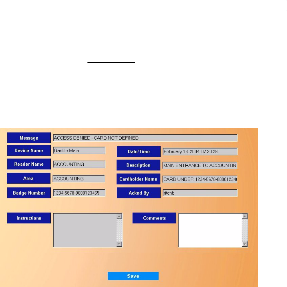
Chapter 2
Using Topaz
41
Now you can click once to select an alarm event in the Alarm Queue Window, double-click to call
up the alarm details, or click MAP (or triple-click the alarm text) to call up the alarm color graphics.
If you have Color Graphics active but do not want to bring it up, when you select an alarm in the
queue window, make sure you do not triple-click the alarm.
Access Events
Access events are also logged in the Alarm Queue Window, for example, when access is denied.
To see more details on an access event, double-click anywhere on the access event in the Alarm
Queue window. The Access Details page displays as shown below.
Figure 43.Access Events Details page

Topa z
User Manual
42
The Access Details page contains the following information.
Note: The only field on the Access Detail page that can be changed or entered at anytime is Comments.
To close the Access Details window, click the X in the upper right corner of the window.
Alarm Control Buttons
Message The message assigned to the event during Reader Event setup.
Description The description assigned to the reader during Reader setup.
Badge Number The whole badge number, including company code, facility code, and card number
assigned to the cardholder.
Cardholder NameThe name of the cardholder assigned to the badge during Cards setup.
Instructions The instruction message text assigned during Alarm Point Option setup.
Reader Name The name of the reader used for this access event by the cardholder, assigned to
the reader during Reader setup.
Date/Time The date and time the access event occurred.
Device Name The name assigned to ACU field panel to which the reader is attached.
Area The name assigned to the security area under Security Area setup.
Acked By The name of the operator logged on to the system when the alarm was
acknowledged.
Comments Comments by the operator (optional).
ACK The Acknowledge button is used to acknowledge the alarm. Select the alarm in
the alarm queue and click the button. The name of the operator currently logged
on to the system is recorded in the Acked By field.
CLEAR Alarm EventThe CLEAR button allows the operator to clear alarms. After an acknowledged
alarm has returned to normal condition, the color of the text turns to green and
the event may be cleared from the Alarm Queue window. To clear an alarm from
the Alarm Queue window, click the alarm to highlight it and then click the
CLEAR button.
DETAIL The DETAIL button displays a sub window with the details for the alarm that is
currently selected in the Alarm Queue.
MAP The MAP button allows you to call up the available maps for alarms. However,
to access this Map feature, under Hardware – Workstation, you must have
Alarm Graphics selected. For more details see Color Graphics Maps on
page 295.
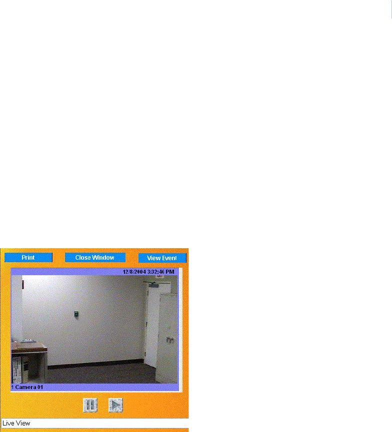
Chapter 2
Using Topaz
43
Video The Video button allows you to call up the camera that was linked to the alarm
event that is highlighted in the alarm queue. Click the Video button and the
Video window displays as shown below.
When you click View Event, the window changes to the clip of the event. This
shows the alarm event starting at the moment the alarm occurred. To see the
moments leading up to the alarm click Reverse. See Video Option on page 49
for more information and an example of a Video Clip window.
Note: There may be a delay of 30-40 seconds after an alarm event occurs before the clip
becomes available by clicking View Event. Click the button once and the clip begins as
soon as it is available.
If you want to print a picture of the live feed, click Print.
To resume watching the live feed click Start.
To Return to the Live Video feed, click View Live and the live video screen
returns.
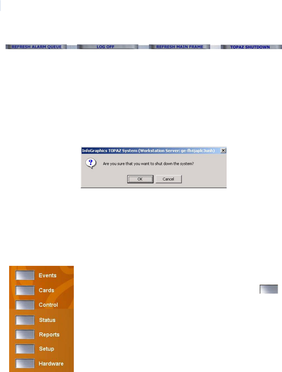
Topa z
User Manual
44
System Control Buttons
These four buttons are located above the alarm queue below the main screen area.
Main Browser Window
REFRESH ALARM
QUEUE
When this button is clicked, the alarm queue is “refreshed” or “repainted”,
to re-display the image. If active alarms disappear from the queue, click
this button to retrieve them.
LOG OFF When this button is clicked, you are logged off the system. Before you can
take any further action on the Topaz system, you must first log back in with
a valid Operator ID and Password.
REFRESH MAIN FRAME When this button is clicked, the current main screen is “refreshed” or
“repainted”, to re-display the image.
TOPAZ SHUTDOWN When this button is clicked, the following message displays:
If you wish to continue shutting down the Topaz application, click OK.
Topaz shuts down and exits to the Windows desktop.
Note: If you are working at a Topaz workstation, the TOPAZ SHUTDOWN button only
stops the local software application. It does not shutdown the server. If you want
to stop the server, click this button on the Server machine.
The third section of the Main browser page is the larger portion of the
screen as shown in part on the left.
The main portion of the Main browser page has a set of silver
navigation buttons that duplicate the Main System navigation buttons at
the left side of the screen. As you move the mouse pointer over the
buttons, they change color slightly. If the left button is clicked while the
button is changed, it navigates to that section of the Topaz System.
You may use either set of buttons to navigate to the selected section of
the Topaz system.
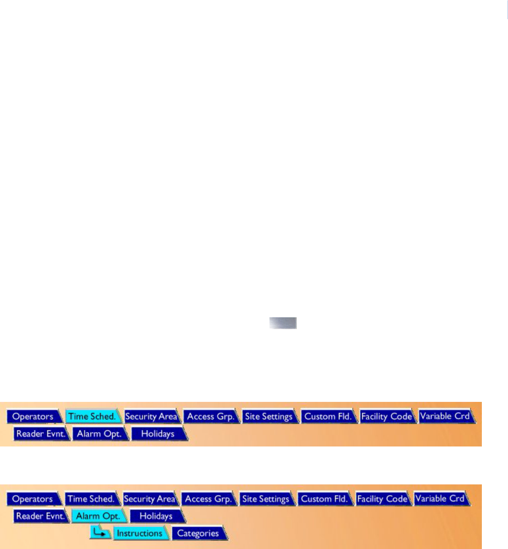
Chapter 2
Using Topaz
45
Navigating Sections of the System
Topaz has 7 basic navigation sections:
•Events
• Cardholder
• Control
•Status
• Reports
•Setup
• Hardware
Each browser page is an independent area. A frame is a section of a browser page. What happens in
one frame may or may not affect the information in another. The frames are different sizes. If more
information is available than can be displayed in the frame, scrollbars appear at the right side or the
bottom of the frame. Scroll up and down or left to right with the bar(s) to display all information.
Navigation Bar Structure
Topaz is a browser-based system, enabling you to use the mouse pointer to click icon buttons to
navigate through the system. You can click one of the buttons, or on any of the main buttons
on the left side of the navigation bar, to access any of the main sections of the software.
Tab Buttons
At times additional pages are made available by clicking the tab buttons from the navigation toolbar
at the top of each page, as shown below for Setup - Time Sched.
At times additional tab buttons appear after clicking on one of the top-level buttons in the navigation
bar, as shown below for Alarm Options, to show Instructions and Categories:
The main navigation buttons on the left of the screen and in the Alarm Queue window at the bottom
of the screen are available at all times while any page of Topaz is selected.
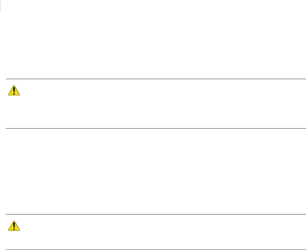
Topa z
User Manual
46
Shutting Down the Software
The following is the recommended method to shut down the software and its peripheral devices. To
prevent loss of data, follow these procedures in the order listed. If your system includes optional
hardware, refer to the equipment's documentation and follow the manufacturer’s instructions.
Procedure
1. Start from any Topaz System page.
2. Click TOPAZ SHUTDOWN in the bottom right corner of the screen. The message “Are you
sure that you want to shut down the system?” displays. Click OK.
3. The Topaz System program closes and returns to the Windows desktop.
At this point you can start another application or continue to shut down the Windows operating
system in the recommended manner.
CAUTION: Once you have shut down the Topaz workstation, all on-line processing stops at the workstation. If the
Topaz Server is powered down, it will not enunciate any alarm reports or access requests. Depending on your
current security hardware, access control decisions may then be handled by the controller (ACU) in the field.
You should have a contingency plan in effect to monitor alarms manually while the Topaz Server is off-line. You
must take whatever precautions necessary to protect the safety of the personnel and equipment in your facility.
CAUTION: Shutting down the Topaz program at the server terminates all communications to the field devices.
Alarms and events will no longer report to the server until the program is restarted and a download is initiated.
Although the alarms and events are stored at the local field panel (ACU) until the server is back on-line, the
amount of data stored is determined by the on-board memory of these devices.

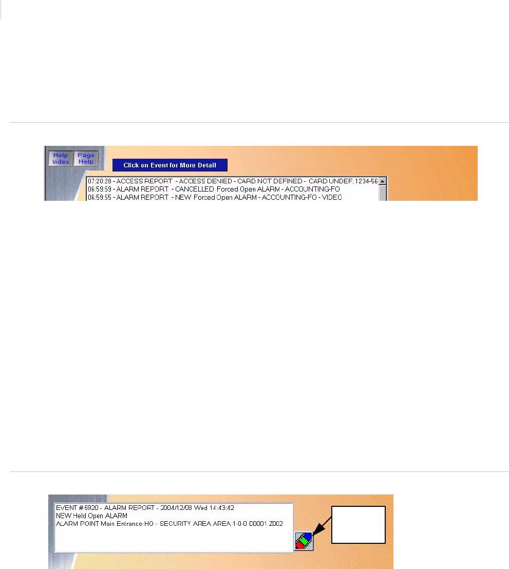
Topa z
User Manual
48
Events Page
The Events page is opened as an independent browser page that appears as an overlay onto the
existing browser page.
Figure 44.Events page
This Events window shows all system events (alarm, system, device, and access events) as they
occur. An event contains information that the system's server records to its database. Each event is
given a sequential event number and a description. However, depending on how event processing is
set up, not all events are displayed and some event numbers appear to be skipped over.
To close the Events window click the X in the right top corner of the window to return to the existing
Main System browser.
The system updates this window constantly, but for the most part you will not see the status change
in this window often, unless there are new events.
If the video option is activated, this page may also contain events that are linked to a video clip. The
video clip can be accessed by opening the Detailed Event Window
Detailed Event Window
More details of each event can be instantly displayed by clicking on the event text inside the queue.
A Detailed Event window displays in a pop-up window. This contains further details of the event.
When finished with the Detailed Event window, click the X in the upper right corner of the window to
close it.
Figure 45.Detailed Event window.
Video Clip
Button
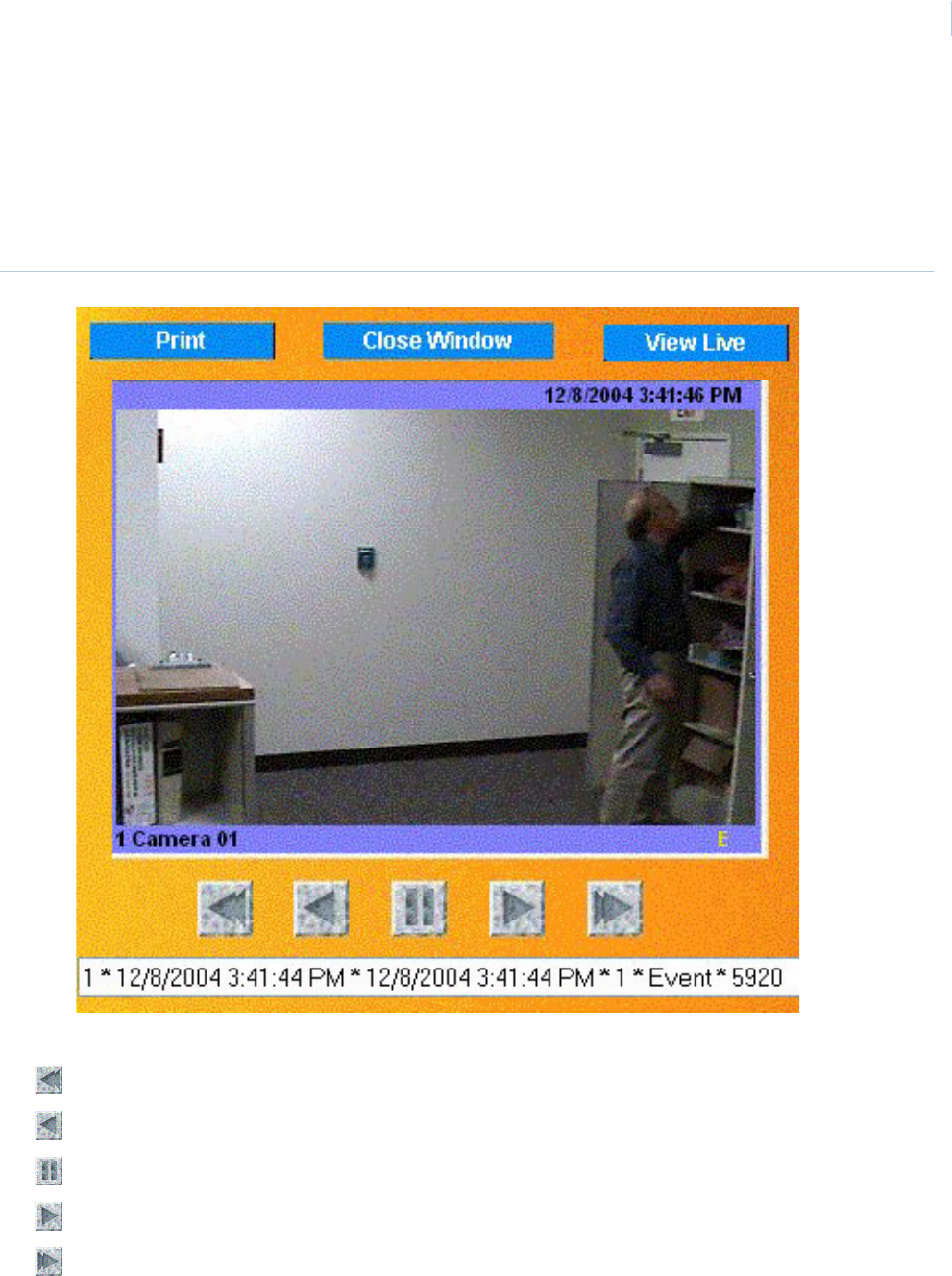
Chapter 3
Events
49
Video Option
If the event has a Video Clip associated with it, the Video button (shown above) appears. To access
the video clip, click Video. The Video opens in another window and plays the clip. The clip begins to
play ten (10) seconds before the point where the event was began. To see what happened before the
event, click Reverse to play the clip backwards.
Figure 46.Video clip
The control buttons are similar to those on a DVR:
Fast Reverse
Play in Reverse
Pause
Play Forward
Fast Forward

Topa z
User Manual
50
If you have found a frame of an event that you want to print, click Print. The image is printed on the
Report Printer.
To see what is happening at the camera that recorded the event clip, click View Live.
When you have finished viewing the video clip, click Close Window to return to the Event Details
window.
CAUTION: Do not close this window using the X in the upper corner. This can cause Topaz to lose communication
with the video. Always click the Close Window button to close the window.

The Cards page allows you to add Cardholders and configure their access
privileges or photo ID.
In this chapter:
Cards . . . . . . . . . . . . . . . . . . . . . . . . . . . . . . . . . . . . . . . . . . . . . 52
Card Setup Page . . . . . . . . . . . . . . . . . . . . . . . . . . . . . . . . . . . . 53
Access Page. . . . . . . . . . . . . . . . . . . . . . . . . . . . . . . . . . . . . . . . 57
Photo ID Page . . . . . . . . . . . . . . . . . . . . . . . . . . . . . . . . . . . . . . 60
Masking Page. . . . . . . . . . . . . . . . . . . . . . . . . . . . . . . . . . . . . . . 65
Information Page . . . . . . . . . . . . . . . . . . . . . . . . . . . . . . . . . . . . 68
Custom Fields Page . . . . . . . . . . . . . . . . . . . . . . . . . . . . . . . . . . 69
Batch Add Page . . . . . . . . . . . . . . . . . . . . . . . . . . . . . . . . . . . . . 70
Batch Delete Page . . . . . . . . . . . . . . . . . . . . . . . . . . . . . . . . . . . 73
Chapter 4 Cards
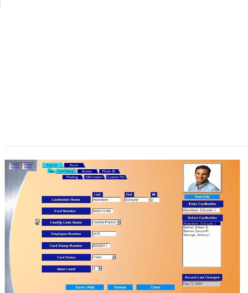
Topa z
User Manual
52
Cards
The Cards button navigates to the following pages, allowing you to add Cardholders and configure
their Access Privileges, Photo ID, etc.
Card Setup Page on page 53
Access Page on page 57
Photo ID Page on page 60
Masking Page on page 65
Information Page on page 68
Custom Fields Page on page 69
These functions are accessed through the navigation bar buttons at the top of the Cards page.
To navigate to the Cards pages, click the Cards button on the left side of the browser window. The
following page displays.
Figure 47.Cards.
You can select a function to view or edit by clicking on the button at the top of the window.
The Cardholder Search window on the right continues to be displayed while navigating through the
Cardholder button pages. The only window that changes when the navigation buttons at the top are
selected is the area in the center of the screen.
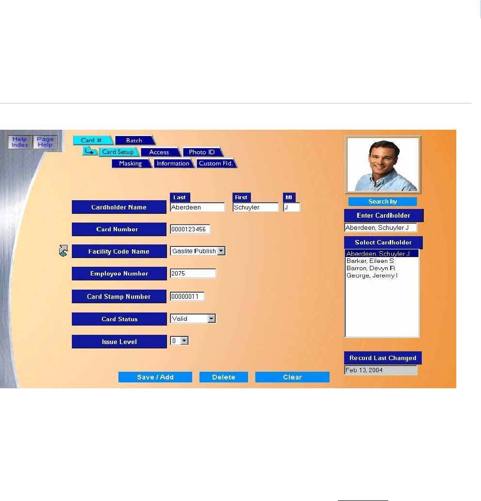
Chapter 4
Cards
53
Card Setup Page
The Card Setup page allows you to add, recall, modify or delete cardholders.
Figure 48.Cards: Card Setup
The Card Setup page contains the following information.
Cardholder Name Enter the Cardholder Name of up to 12 of characters for “First” name, 1 character for “MI” (not
required), and 15 characters for “Last” name. The Cardholder Name is a required field.
Note: You must know the encoded number of the card including the company and facility codes
before continuing. The number is listed on a document which was included with the card
when shipped, unless you requested custom cards with the card number printed on the
back of the card.
Card Number Enter the Card Number of up to 10 digits. The Card Number is a required field.
Note: The Card Number is the only field that may NOT be repeated for the same Facility
(Company Code plus Facility Code). You can have two identical Card Numbers as long as
the Facilities are different.
Facility Code Select the Facility Code by clicking on the down arrow and selecting from the list of Facility Codes.
To configure a Facility Code, click the link arrow to the left of the field to open the Facility Code
configuration page. When you have completed the configuration, close the page by clicking Save.
Employee Number This field is optional and can be a maximum of 12 alphanumeric characters.
Card Stamp Number This is optional and can be a maximum of 8 numeric characters. The number is printed on the back
of the card. If you request it, the number is also the card number (and the encoded card number).
However, to be used as the Card Number, the Card Stamp Number must be entered into the Card
Number field.
Topa z
User Manual
54
How to add a new cardholder
1. Click Clear to clear any existing data from the fields.
2. Enter the information on the Card Setup page for the new cardholder.
3. Once all data for the new cardholder has been entered, click Save/Add. The message,
“Operation Complete” displays.
How to recall a cardholder
There are five ways to recall a cardholder in the database. The default is by Name. You can select a
different filter by moving the mouse pointer to the Search by button. The drop-down list displays
allowing you to select one of four (4) other options. As the mouse pointer is moved over the search
fields, they change color. When the desired field is highlighted, click the left mouse button to select it.
Card Status The Card Status defaults to Valid, meaning that the card is a usable card in the system.
Click on the down arrow to select other options:
• Lost (card is denied access)
• Stolen (card is denied access)
• Inactive (card is denied access)
• Terminated (card is denied access)
The status of these options indicates to the system that the card is not valid and to deny access
under any circumstances.
Issue Level The Issue Level only applies to magnetic stripe cards and is the number of times this card number
has been issued (given to a single Employee). A card may be reissued if the Employee reported his
or her card lost or stolen. Click the down arrow and select from the list of forty-nine (49) issue levels.
Save/Add Click to save the cardholder information to the database.
After clicking Save, one of three messages appears.
• If “Operation Complete” displays, no further changes are needed.
• If “Duplicate Record” displays, then the Card Number has been repeated. Use a new Card
Number and try saving again.
• If “Operation Failed” displays, then a required field was not entered (Card Number or other
field). Enter the required information and try saving again.
Note: If Photo Badging is being used, once the picture of the employee is added on the Photo ID
page, it displays in the top right corner of the page.
Clear At any point, if you wish to clear the entered information, click Clear.
CAUTION: Clicking Clear before clicking Save deletes newly entered data.
Recall By: • Name (default)
• Card Number
• Serial Number
• Employee Number
• Vehicle License
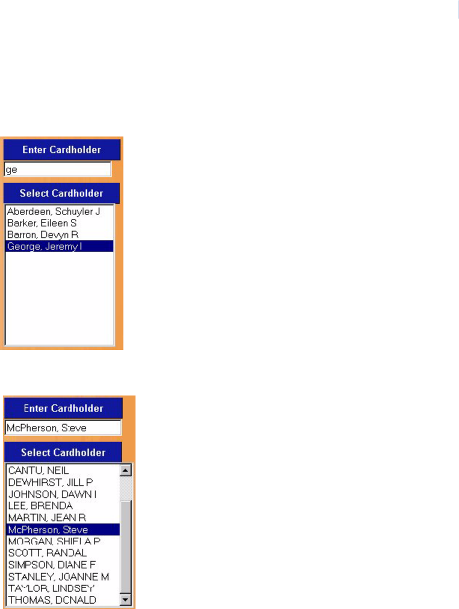
Chapter 4
Cards
55
Recall by Name
• In the Enter Cardholder window, as you start typing the name of the cardholder, the list
highlights the name in the list. For example, if “m” is typed, then “Martin, Jean” is highlighted
in the scrolling Select Cardholder window. If this is the cardholder you are looking for, click
the highlighted name in the Select Cardholder window. The data window fills in with Jean
Martin's data.
• You may also scroll through the Select Cardholder list in the window. When the desired
cardholder name is located, click the name of the cardholder. The data window fills in with the
cardholder's data that you just clicked on.
Topa z
User Manual
56
• At the bottom of the Select Cardholder window the Record Last Changed indicates the last
date any changes or modifications were made to the current cardholder record being
displayed.
Note: It may be necessary to use the scrollbar on the right side of the cardholder page to move the window up to show
the Record Last Changed date.
Using the other Search By filters
1. Select [filter] that you want to use from the Search By button.
2. The Select Cardholder window now contains all cards in the system with the [selected filter]
information displayed.
3. Begin typing the first digits of the desired information and the first card matching the typed
information is highlighted. When the correct card is highlighted, click the highlighted card.
The employee information fills the page.
Note: When searching by Serial Number, the numbers that appear in the Select Cardholder field are the numbers that
were entered in the Card Stamp Number field on the Cards>Setup page.
How to modify a cardholder
1. Follow the Recall Cardholder procedure to recall a cardholder record to be modified.
2. Make the desired changes to any field except the card number.
3. Once all changes for the cardholder have been made, click Save/Add. The message
“Operation Complete” appears.
How to delete a cardholder
1. Locate the cardholder to delete.
2. Once the cardholder record is found and the database record is displayed, click Delete.
3. A message “Are you sure that you want to delete this record?” displays. Click OK to continue.
4. The message “Operation Complete” should be displayed indicating that the cardholder has
been deleted from the database.
5. The cardholder's record is now deleted from the database and the cardholder's name has
been removed from the Selected Cardholder list on the right side of the screen.
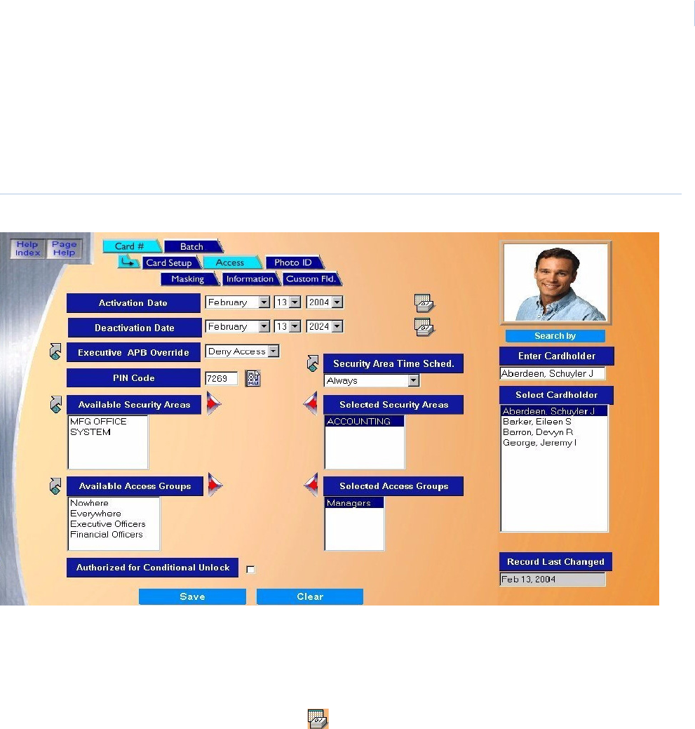
Chapter 4
Cards
57
Access Page
The Access Privileges page allows you to configure security areas and access groups.
While viewing any Cards page, click the Access tab button at the top of the window. The navigation
button turns a lighter blue and the Access page displays as shown below.
Figure 49.Cards: Access
The Access page contains the following information.
Activation Date This is the date the card becomes active, with a default of today’s date as retrieved from the
server. This is not necessarily the same as the date the card was entered into the Topaz system.
For example, you can enter a batch of cards that will become effective next week. The format of
the date may be selected in Setup - Site Settings. A full calendar can be displayed and used to
select this date by clicking the Calendar button.
Deactivation Date This is the date the card is no longer authorized for use and access is denied. The default is 20
years from the Activation date. A full calendar can be displayed and used to select this date by
clicking the Calendar.

Topa z
User Manual
58
Executive APB Override This field only applies if Anti-Passback is first enabled under Setup - Site Settings. You can do this
immediately by selecting the link arrow to the left side of Executive APB Override to go directly to
the Site Settings page. Under Anti-Passback, you can select Enable to activate the Anti-Passback
feature for this site.
In addition, you must select cardholders and security areas under Control, Reset APB.
There are two options for Executive APB Override
• Deny Access - If APB is violated, the system denies access to the area and generates an
access denied alarm. This is the normal selection for most cardholders, otherwise Anti-
Passback has little value.
• Grant Access - If APB is violated, the system allows access to the area, provided the
cardholder is authorized for entry to that area during that time, etc. Executive APB Override
applies only to Anti-Passback conditions. It does not override other access rules. This will still
trigger an alarm.
For more information, see Appendix C, Anti-Passback.
PIN Code The PIN Code is the Personal Identification Number or password (maximum number of digits is 4)
that the cardholder uses at the keypad for access. If the PIN is less than 4 digits, then leading
zeros must be entered. For example, if the PIN is 23 and the PIN code is set for 4 digits, you must
enter 0023 at the card reader. You can also use the asterisk after the number, for example, 23*.
If keypads are not enabled on the Reader Setup Page, then no PIN Code is required.
The small icon to the right of the PIN Code field is a PIN Code generator.
Available Security AreasSelect the Security Areas that the cardholder is authorized to access. Do this by clicking on the
name of the Security Area listed in the Available Security Areas window.
Note: If the same group of security areas is to be assigned to a number of cardholders, you
may want to take advantage of configuring the group of security areas as an Access
Group. Refer to “Available Access Groups” to add the access group to the cardholder. Go
to Access Group Page on page 172 to configure a new Access Group.
• Click the right arrow to add the selected security area to the Selected Security Areas window.
Repeat this step until all desired security areas are added to the Selected Security Areas
window. Up to eight (8) security areas may be selected.
• To remove a selected area from the Selected Security Areas window, click the security area
name to remove and click the left arrow.
• If the desired Security Area is not available and you need to configure one, click the link arrow
to the left of Available Security Areas. This opens the Security Area configuration page. Once
you have completed the configuration, close the page by clicking Save. This returns you to
the Access page.
Available Access
Groups
• To select the Access Groups that the cardholder is authorized to access, click the name of the
Access Group listed in the Available Access Groups window and click the right arrow to add
the access group to the Selected Access Groups window. Repeat this step until all desired
access groups are added to the Selected Access Groups window. Up to eight (8) access
groups may be selected.
• To remove a selected area from the Selected Access Groups window, click the access group
name to remove and click the left arrow.
• If the desired Access Group is not available and you need to configure one, click the link
arrow to the left of Available Access Group. This opens the Access Group configuration page.
Once you have completed the configuration, close the page by clicking Save. This returns
you to the Access page.

Chapter 4
Cards
59
Security Area Time
Schedule
The Security Area Time Schedule defines the times during which the cardholder has access to
certain Security Areas or Access Groups.
Click the name of the area or group, then from the Security Area Time Schedule drop-down list
select the time for authorization. Repeat until all areas or groups have a time schedule.
If the desired Time Schedule is not available and you need to configure one, click the link arrow to
the left of Security Area Time Schedule. This opens the Time Schedule configuration page. Once
you have completed the configuration, close the page by clicking Save. This returns you to the
Access page.
Authorized for
Conditional Unlock
This field works in conjunction with readers that are configured to Conditionally Unlock during a
time schedule. When this option is selected, the door does not unlock until a designated
cardholder accesses the area after the start of the unlock Time Schedule.
Example: The lobby reader door is configured to conditionally unlock at 07:00 (7am). At 7 a.m. the
door allows cardholders to access the lobby, but remains locked to Non-Cardholders until a
cardholder that is Authorized for Conditional Unlock accesses the lobby reader.
Save When configuration of the Access Page is complete, click Save to save the cardholder record.
After clicking Save, one of the following messages appears.
• If “Operation Complete” is displayed, then no further changes are needed.
• If “Operation Failed” is displayed, then a required field was not entered. Enter the field and try
again.

Topa z
User Manual
60
Photo ID Page
Introduction to Photo Badging
The Photo Badging facility is available as standard software in all versions of the Topaz Series
system.
The server or workstation configured as an enrollment station requires special hardware as
described below. The verification station, which does not have the capability to take photos or print
badges, needs no special hardware for the display of photos or badges.
The Topaz Photo Badging Software gives you a full Badge Design package with multi-layer design
tools, a full editing package including copy, paste, automatic centering, and full drag and drop
capabilities. The design package also includes snap to grid facilities, automatically scalable fonts
with auto kerning, and landscaping badge templates, an extensive color palette with individual color
design facilities, and a full badge design check and test print capability.
It includes a sophisticated photo capture facility, providing vertical and horizontal photo centering
controls, brightness, contrast, color, intensity and hue controls for the photo image, and a multi frame
capture which allows you to chose the best image to be included on the badge.
The system allows you to enter text, signatures, and database information directly from the
cardholder database, and to print bitmaps, photos, and text based on conditions set for any of the
fields in the Cardholder record.
The Topaz Photo Badging software can be used with a range of industry standard dye sublimation
printers, like the Eltron P310-C direct connect printer. The software also supports double-sided
printing, automatic magnetic stripe encoding, and use of hologram overlays.
Once the required video hardware is available in the system, the software provides you with a
complete set of tools and facilities necessary to design and print photo ID badges and all other
functions outlined above.
For additional hardware requirements and options for each photo-badge enrollment station, see
System Requirements on page 3.
Enabling Photo Badging
The Photo ID page is the badging and photo page, which enables you to take/import photos, assign
a badge template, and print the badge, etc.
Before you can use the Photo ID features, you must have Photo Badging selected on the
Hardware – Workstation page.
To enable Photo Badging:
1. Select the Hardware button on the left side of the main screen.
2. Select Workstation.
3. Under Workstation, select the name of your workstation.
4. Select Photo Badging by clicking in the check box.
5. Click Save.
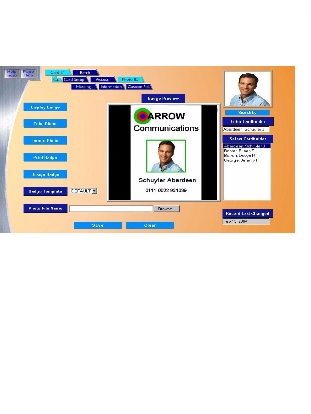
Chapter 4
Cards
61
While viewing any Cards page, click the Photo ID tab button. The following page displays.
Figure 50.Cards: Photo ID
The Photo ID page contains the following information.
Display Badge To display a badge, you must first select a cardholder from the Select Cardholder window. Then click
Display Badge. The photo (if available) for that cardholder appears in the top right corner of the screen
and the full badge for that cardholder appears in the large Badge Preview window.
Take Photo Verify that the correct cardholder’s record is displayed before taking the photo. Then click Take Photo.
Note: A video card (if camera is not USB) and camera are required before you can take a photo. Also,
make sure the color and resolution for your monitor is set to 1024x768 and 16 bit High Color.
See How to take a photo on page 62.
Importing Photo Importing a photo allows you to display and use a digital photo file instead of a live photo. The imported
photo should not exceed 200k in size.
.See How to import a photo on page 63.
Print Badge To print the badge for the selected cardholder, click Print Badge. The badge displays in a full window.
Then the Print dialog box displays.
See How to print a badge on page 64.
Design Badge To access the badge design utility, click Design Badge.
A new window for designing badges is presented. For more details on designing a badge template, see
Badge Design on page 267.
Badge TemplateFrom the drop-down list of pre-designed badge templates select the template for the currently selected
cardholder.
Note: To create a new badge template, see Badge Design on page 267 for a complete user guide on
designing a badge template.
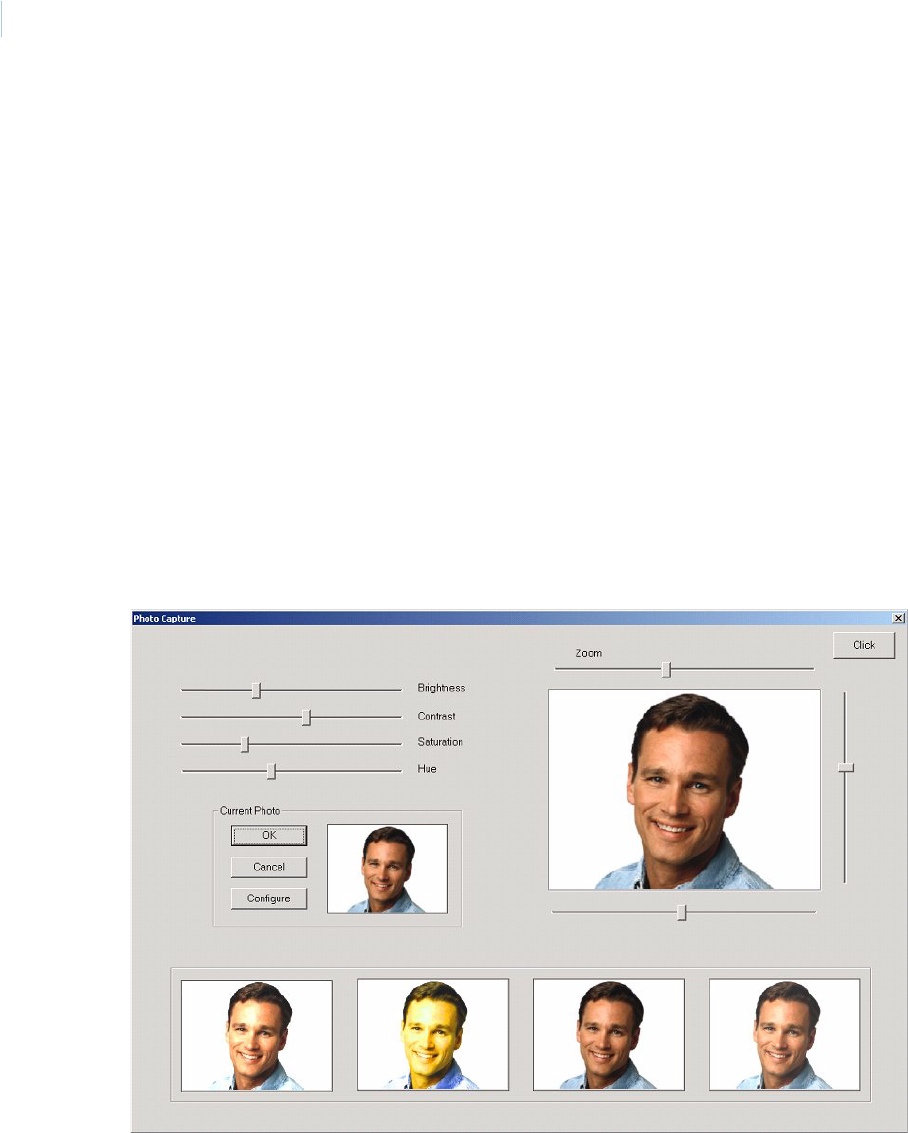
Topa z
User Manual
62
How to take a photo
1. Verify that the correct cardholder’s record is displayed before taking the photo.
2. Then click Take Photo.
Note: A video card (if camera is not USB) and camera are required before you can take a photo. Also, make
sure the color and resolution for your computer’s monitor is set to 1024x768 and 16 bit High Color.
The cardholder’s image appears in the live video screen in the upper right of the new
screen shown below. To the right and below the live video image are adjustment bars in
scroll bars, which you may use to center the subject in the screen area. You may also
adjust the Zoom bar to adjust how the image fills the screen.
To the lower left of the live video image is an area that displays the current photograph (if
any) in the cardholder database for that subject. In the left upper part of the screen are
the adjustment bars that you can use to control the Brightness, Contrast, Saturation,
and Hue. As you adjust these controls, the live image changes accordingly.
3. To take a photo, click the Click button and the photograph appears in one of the four screen
spaces at the bottom of the screen, starting at the left box. Each time you click the Click
button, another photograph is added to the four screen spaces at the base of the screen. As
the photos are taken they are added from left to right. You do not have to take four photos.
Save Once all Photo Badging data for the cardholder has been entered, click Save.
After clicking Save one of the following messages appears:
• If “Operation Complete” is displayed, then no further changes are needed.
• If “Duplicate Record” is displayed, then the Card Number has been repeated. Try a new number.
• If “Operation Failed” is displayed, then a required field was not entered. Enter the field and try again.
Clear At any point if you wish clear to clear the entered information, click Clear.
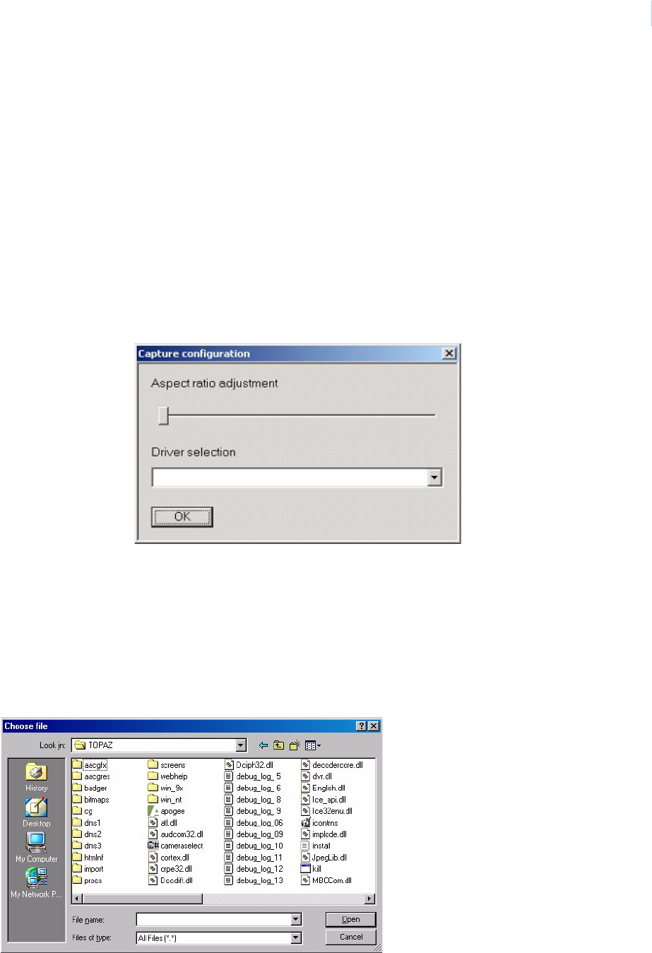
Chapter 4
Cards
63
4. To select which photograph is to be used on the badge, move the mouse over the selected
photograph in one of the four photo boxes at the bottom of the screen and click the left mouse
button. This displays the newly selected photo in the Current Photo box above. Click OK to
the left of the Current Photo to save this image into the cardholder database.
5. If you changed any of the video adjustments (Brightness, Contrast, etc.), a dialog box
appears asking you if the new settings should be saved. If you select Yes, these new
adjustments are saved for use with the photo of the next cardholder. If you select No, the
original settings are restored for the next cardholder. With either answer, the photo is saved
to the cardholder database and screen reverts to the Card database screen.
6. At anytime, you can click Cancel and the screen reverts to the Card database screen.
The Configure button allows you to adjust the aspect ratio of the image. Sometimes the
image saved to the badge warps slightly distorting the appearance of the cardholder. If
this happens, you can adjust the aspect using the slider on the pop-up window.
The driver you are using for the cameras appears in the Driver to use drop-down list.
How to import a photo
Importing a photo allows you to display and use a digital photo file instead of a live photo. The
imported photo should not exceed 200k in size.
1. Start by clicking Browse to the right of the Photo File Name field.
The Choose File window opens.
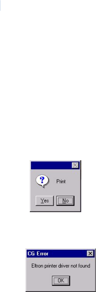
Topa z
User Manual
64
2. You may browse to select any folder. Sample photos are stored under Badger / Photos.
3. Locate the “jpg” file to import and click Open.
The name of the file appears in the Photo File Name field.
4. Click Import Photo to display that image in the upper right corner of the screen.
How to print a badge
Note: The first time you print a badge, you must first select a printer from within the Badge Design program.
Before printing the badge, you may wish to preview it to make sure it is correct by clicking Display
Badge.
To print the badge for the selected cardholder:
1. Click Print Badge.
The badge displays in a full window. Then the Print dialog box displays.
2. Click Yes to print.
If you do not have the proper equipment for printing badges, an error message like this
displays:
3. Click OK to continue.
The message “Operation Complete” displays.
4. Click OK to continue.
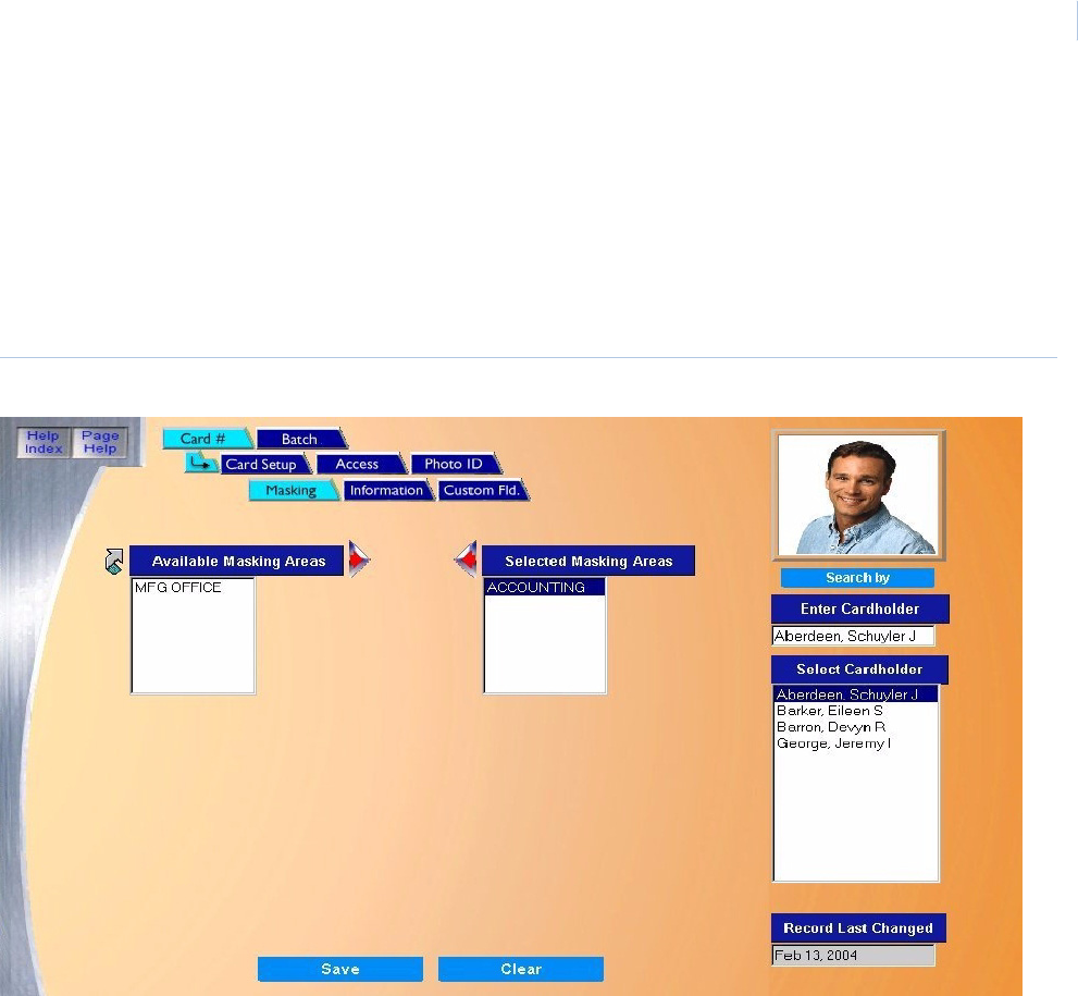
Chapter 4
Cards
65
Masking Page
The Masking page allows you to select the Security Areas that the cardholder is authorized to Mask/
Unmask. “Masking” means turning off the alarm for that Security Area and “Unmasking” means
turning the alarm back on.
While viewing any Cards page, click the Masking tab button at the top of the window. The following
page displays:
Figure 51..Cards: Masking
Only Security Areas where masking is allowed are listed.
Configuring a Security Area for Masking
To mask any alarms, the cardholder must first be allowed into the Security Area. If you want to
configure an area for masking that does not appear in the list of Available Masking Areas (on the
Cards – Masking screen), click the link arrow to the left of the Available Masking Areas field. This
brings up an additional window showing the Security Area page, as shown below:
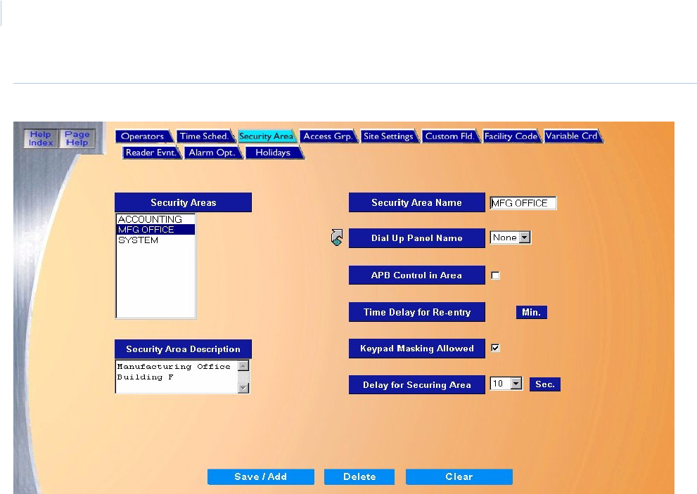
Topa z
User Manual
66
Figure 52.Security Area.
Click the name under Security Areas that you want to allow Keypad Masking. That name appears in
the Security Area Name field on the right.
On this screen, select Keypad Masking Allowed. Repeat this process for all Security Areas in
which you want to allow Keypad Masking.
When you are done, click Save/Add to save your changes and return you to the Masking page.
The areas that you configured for Keypad Masking Allowed now appear in the list of Available
Masking Areas on the Cards – Masking screen. You can then select those areas to allow keypad
masking.
Note: If a security area has Keypad Masking Allowed checked, the cardholder cannot gain access to the area until the
area is Masked.
How to add an area for masking
1. To select the Masking Area that the cardholder is authorized to Mask/Unmask, click the name
of the area listed in the Available Masking Areas window and click the right arrow to add the
Masking Area to the Selected Masking Areas window. Repeat this step until all desired
Masking Areas are added to the Selected Masking Areas window.
2. To remove a selected area from the Selected Masking Areas window, click the Masking Area
name to remove and click the left arrow. This moves the area back into the Available Masking
Areas window.
3. Once all Masking data for the cardholder has been selected, click Save.
Chapter 4
Cards
67
4. After clicking Save one of the following messages appears.
• If “Operation Complete” is displayed, then no further changes are needed.
• If “Operation Failed” is displayed, then a required field was not entered. Enter the field
and try again.
At any point if you wish to clear the entered information click Clear.
How to use keypad masking
Keypad Masking allows the cardholder to mask / unmask the alarms associated with a security area
by using their PIN as described below.
Keypad Masking requires three conditions to be set, in the following order:
1. Select the area under Setup – Security Area to allow Keypad Masking.
2. To mask any alarms, the cardholder must first be allowed access into that Security Area.
Under Cards – Access, select the cardholder, then the area under Available Security Areas
and move that area to the Selected Security Areas column.
3. The cardholder must have that Masking Security area selected. Under Cards – Masking,
move the area from Available Masking Areas to Selected Masking Areas.
4. Click Save.
To use the keypad to mask (unsecure) an area, the cardholder/user must enter the PIN + 20 to mask
the alarm. For example, if the PIN is 1023, the cardholder must enter 1043 to mask that security
area. The alarms will be turned off and the door will unlock.
Note: If a security area has Keypad Masking Allowed checked, the cardholder cannot gain access to the area until the
area is Masked.
If one cardholder unmasks that alarm, anyone with access to that area can enter. The alarm will be
off.
To secure the area, an authorized cardholder/user must enter the PIN + 10 to unmask the alarm. For
example, if the PIN is 1023, the cardholder must enter 1033 to unmask that security area. The
alarms will then be set (on).
Note: If an alarm associated with the area being unmasked is active at the time you are attempting to unmask the area,
the request is denied. All alarms associated with the security area must be secure before an unmask request is
granted.
CAUTION: Do not click Clear before clicking Save or newly entered data will be lost.
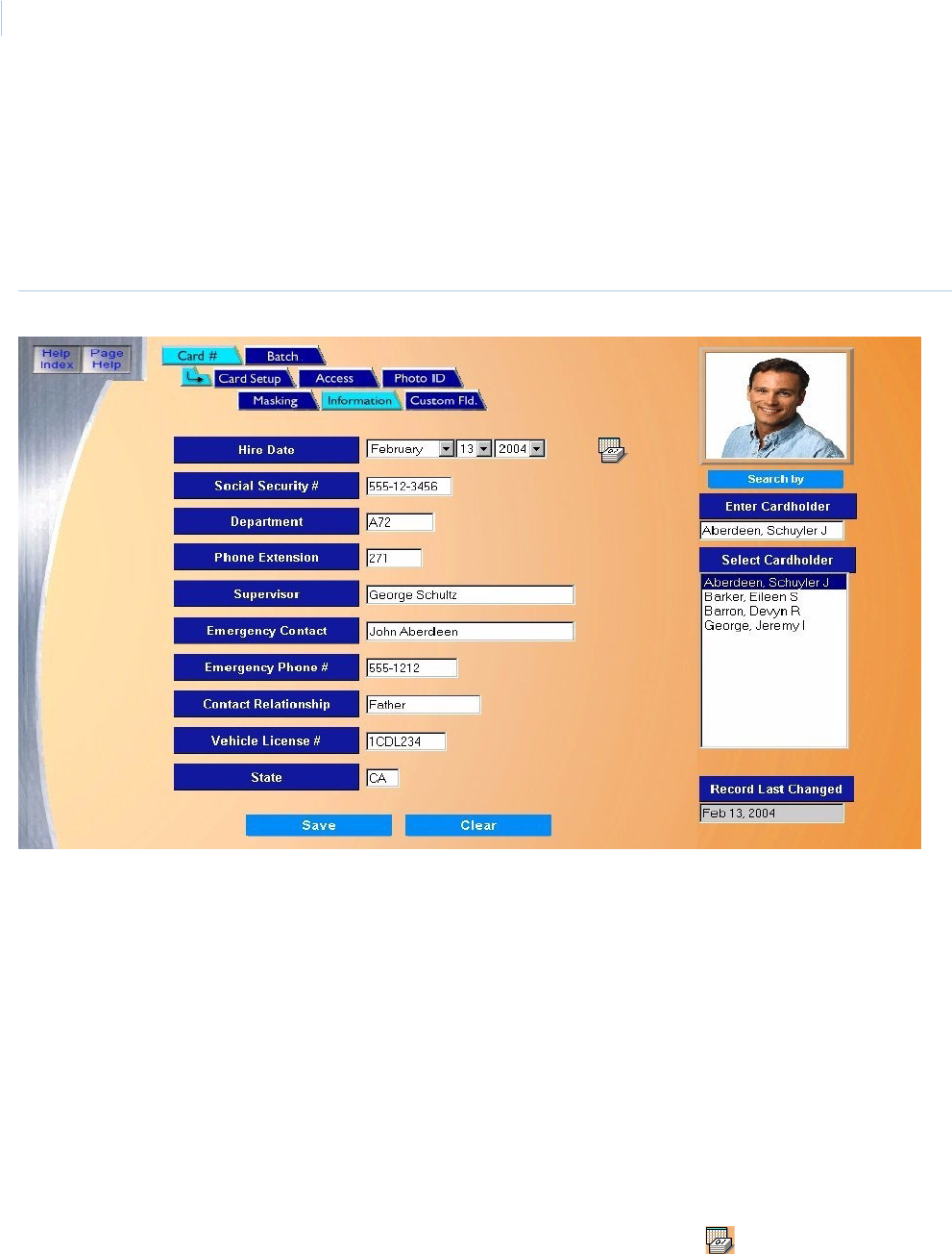
Topa z
User Manual
68
Information Page
The Information page contains additional detailed information on the cardholder. The information in
these fields is optional.
To navigate to the Information page, from any page within the Cards pages click the Information
tab button at the top of the screen. The following page displays.
Figure 53.Cards: Information
The maximum number of characters for each field is shown below.
For the Hire Date field, a full calendar can be displayed by clicking on the Calendar icon.
Enter all desired information on the cardholder and click Save.
Field Name Max Characters
Hire Date N/A
Social Security # 11
Department 8
Phone Extension 6
Supervisor 32
Emergency Contact 32
Emergency Phone # 12
Contact Relationship 16
Vehicle License # 10
State 2
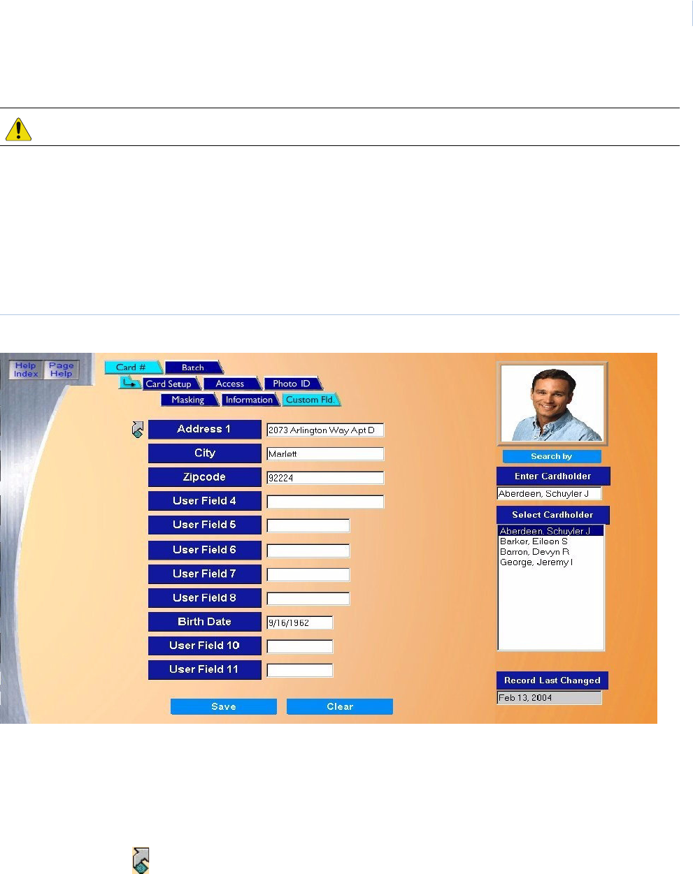
Chapter 4
Cards
69
At any point if you wish to clear the entered information, click Clear.
Custom Fields Page
The Custom Fields page contains eleven (11) additional fields you may custom configure for
additional cardholder information not already available on the Information Page.
To navigate to the Custom Fields page, from any page within the Cards pages click the Custom
Fld. tab button at the top of the screen. The following page displays:
Figure 54.Cards: Custom Fields.
• User Field 1 - 4 can contain a maximum of 24 alphanumeric characters.
• User Field 5 - 8 can contain a maximum of 16 alphanumeric characters.
• User Field 9 - 11 can contain a maximum of 12 alphanumeric characters.
The titles or names for these fields are optional and can be configured on the Custom Fields Page on
page 177.
Clicking on the link to the left of the first field name on the screen above opens a new window
allowing you to configure the field names. After making changes, click Save to close the window. You
are returned to the Custom Fields page to continue entering cardholder information.
CAUTION: Do not click Clear before clicking Save or newly entered data will be lost.
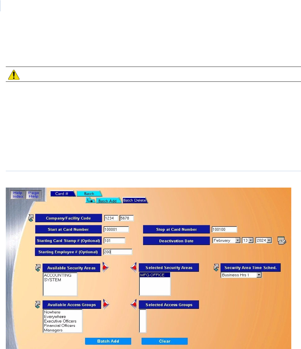
Topa z
User Manual
70
In the Cardholder Custom Fields window add any additional information for the currently selected
cardholder to all desired fields and click Save.
At any point if you wish to clear the entered information, click Clear.
Batch Add Page
The Batch Add Page allows you to add a maximum of 250 cards at one time. All cards being added
must be configured for the same Deactivation Date, Company/Facility Code, list of Security Areas
and/or Groups, and Time Schedules assigned to the areas/groups.
To navigate to the Batch Add page, from any page within the Cards pages click the Batch tab
button at the top of the screen. When you have completed using the Batch Add function, click the
Card # button to access the other page buttons.
Figure 55.Cards: Batch Add
CAUTION: Clicking Clear before clicking Save will delete newly entered data.

Chapter 4
Cards
71
The Batch Add page contains the following information.
Company/Facility Code Enter up to 4 numbers for the Company Code in the first field that is encoded on the cards being
added, and then enter up to 4 numbers for the Facility Code in the second field.
Start at Card Number Enter up to 10 digits for the starting card number.
Stop at Card Number Enter up to 10 digits for the ending card number. This range of cards (up to a maximum of 250
cards) is added to Topaz. For example, if the starting card number is 136001 and the Stop at
Number is 136250, then 250 cards are added to the system.
An alternative method of entering the Start at Card Number and Stop at Card Number is to use
readers to enter the card number range.
See How to enter the card number range using a reader on page 72.
Starting Card Stamp
Number
Enter up to 8 digits for the Starting card Stamp Number. This would be the number on the back of
the first card being added to the system.
Note: The Card Stamp Number is incremented one number at a time. For example, if you enter
5299 for the starting number and you are adding 100 cards, then the Card Stamp number
on the first card is 5299 and the last card is 5398.
Starting Employee
Number
Enter up to 12 alphanumeric characters for the Starting Employee Number to be added to the
system. The employee number is incremented by one for each card added to the system.
Deactivation Date Select the date that all cards being added to the system will be deactivated. The default date is 20
years from the current date. A calendar is available by clicking the Calendar icon.
Available Security
Areas / Selected
Security Areas
• To select the Security Areas that all the cards being added are authorized to access, click the
name of the Security Area listed in the Available Security Areas window.
• Click the right arrow to add the selected security area to the Selected Security Areas window.
Repeat this step until all desired security areas are added to the Selected Security Areas
window. Up to eight (8) security areas per card may be selected.
• To remove a selected area from the Selected Security Areas window, click the security area
name to remove and click the left arrow.
• If the desired Security Area is not available and you need to configure one, click the link arrow
to the left of Available Security Areas. This opens the Security Area configuration page. Once
you have completed the configuration, close the page by clicking Save.
Available Access
Groups / Selected
Access Groups
• To select the Access Groups that all cards being added are authorized to access, click the
name of the Access Group listed in the Available Access Groups window.
• Click the right arrow to add the access group to the Selected Access Groups window. Repeat
this step until all desired access groups are added to the Selected Access Groups window.
You can use up to eight (8) access groups per card.
• To remove a selected area from the Selected Access Groups window, click the access group
name to remove and click the left arrow.
• If the desired Access Group is not available and you need to configure one, click the link arrow
to the left of Available Access Group. This opens the Access Group configuration page. Once
you have completed the configuration, close the page by clicking Save.
Security Area Time
Schedule
The Security Area Time Schedule defines the times during which the cards have access to certain
Security Areas or Access Groups.
To set up a Security Area Time Schedule, see How to set up a Security Area time schedule on
page 72.
Clear At any point if you wish to clear the entered information, click Clear.
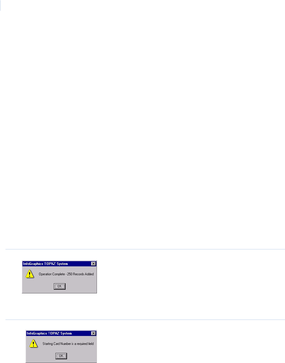
Topa z
User Manual
72
How to enter the card number range using a reader
An alternative method of entering the Start at Card Number and Stop at Card Number is the
following:
1. Leave the Start at Card Number and Stop at Card Number fields blank.
2. Take the first and last cards in the batch to any reader attached to the system.
3. Swipe the first card and the last card.
4. Return to the computer with the Batch Add Page showing. The card numbers display in those
fields.
This method is useful if you have a reader close by and/or the card numbers are not stamped on the
cards. Some firms order cards with the encoded card numbers different from the numbers stamped
on the cards for security reasons. They may use an offset value (for example, the card number is 10
more than the card stamp number) or a formula to determine the offset value, making it more difficult
for anyone to gain access who has a card and does not know the card number.
How to set up a Security Area time schedule
1. Click the name of the area or group, then from the Security Area Time Schedule drop-down
list select the time for authorization. Repeat until all areas or groups have a time schedule.
2. If the desired Time Schedule is not available and you need to configure one, click the link
arrow to the left of Security Area Time Schedule. This opens the Time Schedule
configuration page. Once you have completed the configuration, close the page by clicking
Save.
3. When you have finished configuring the Batch Add Page, click Batch Add. The message
“Operation Complete” appears indicating the number of cards that were added to the system.
Figure 56.Operation Complete
4. If not, the message advises you which field has been left out. For example, if you left the Start
at Card Number blank, the following message displays:
Figure 57.Starting Card Number required
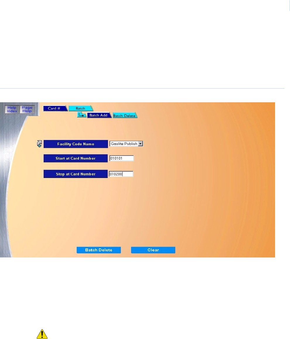
Chapter 4
Cards
73
Batch Delete Page
The Batch Delete page allows you to delete a range of cards in one easy step.
To navigate to the Batch Delete page, from any page within the Cards pages click the Batch tab
button at the top of the screen. Then click the Batch Delete tab button. When you have completed
using the Batch function, click the Card # button to access the other page buttons.
Figure 58.Cards: Batch Delete
The Batch Delete page contains the following information.
Facility Code Name From the drop-down list, select the name of a facility code you want to use.
If the desired Facility Code Name is not available and you need to configure one, click the link arrow
to the left. This opens the Facility Code configuration page. Once you have completed the
configuration, close the page by clicking Save.
Start at Card Number Enter the first card number to be deleted.
Stop at Card Number Enter the last card number to be deleted. This range of cards (up to a maximum of 250 cards) is
deleted from Topaz.
CAUTION: Remember that all cards between the Start and Stop numbers are also deleted!
Clear At any point, if you wish to clear the entered information, click Clear.
Batch Delete When you are sure that you have the correct card numbers selected to be deleted, click Batch
Delete.
The message “Operation Complete” appears indicating the number of cards that were deleted from
the system. If not, the message advises you which field has been left out.
Card # When you have completed using the Batch function, click the Card # button to access the other page
buttons.

Topa z
User Manual
74

This chapter includes information about using the Control button, which
allows you to control readers, alarm points, and access trace, reset anti-
passback, perform service functions, and back up / restore the Topaz
System databases.
In this chapter:
Overview. . . . . . . . . . . . . . . . . . . . . . . . . . . . . . . . . . . . . . . . . . . 76
Reader Control Page . . . . . . . . . . . . . . . . . . . . . . . . . . . . . . . . . 77
Alarm Point Control Page . . . . . . . . . . . . . . . . . . . . . . . . . . . . . . 79
Relay Control Page . . . . . . . . . . . . . . . . . . . . . . . . . . . . . . . . . . 81
Access Trace Page. . . . . . . . . . . . . . . . . . . . . . . . . . . . . . . . . . . 83
Reset APB Page (Anti-Passback) . . . . . . . . . . . . . . . . . . . . . . . 85
Service . . . . . . . . . . . . . . . . . . . . . . . . . . . . . . . . . . . . . . . . . . . . 87
Panel Page . . . . . . . . . . . . . . . . . . . . . . . . . . . . . . . . . . . . . . . . . 87
Database Page. . . . . . . . . . . . . . . . . . . . . . . . . . . . . . . . . . . . . . 90
Back Up\Restore Database Page. . . . . . . . . . . . . . . . . . . . . . . . 93
Diagnostic Settings Page . . . . . . . . . . . . . . . . . . . . . . . . . . . . . . 95
Chapter 5 Control
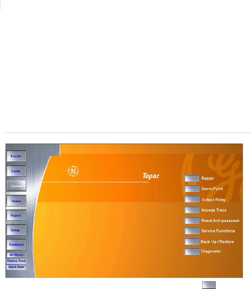
Topa z
User Manual
76
Overview
The following pages are available through the main Control page.
•Reader Control Page on page 77
•Alarm Point Control Page on page 79
•Relay Control Page on page 81
•Access Trace Page on page 83
•Reset APB Page (Anti-Passback) on page 85
•Database Page on page 90
•Back Up\Restore Database Page on page 93
•Diagnostic Settings Page on page 95
To navigate to the Control page, click the Control button in the left main toolbar. The following
screen displays.
Figure 59.Control
Each of the seven options above may be selected by clicking the corresponding button on the
right side of the screen.While viewing any one of the Control screens, you can refresh the screen by
clicking the tab for the screen again.
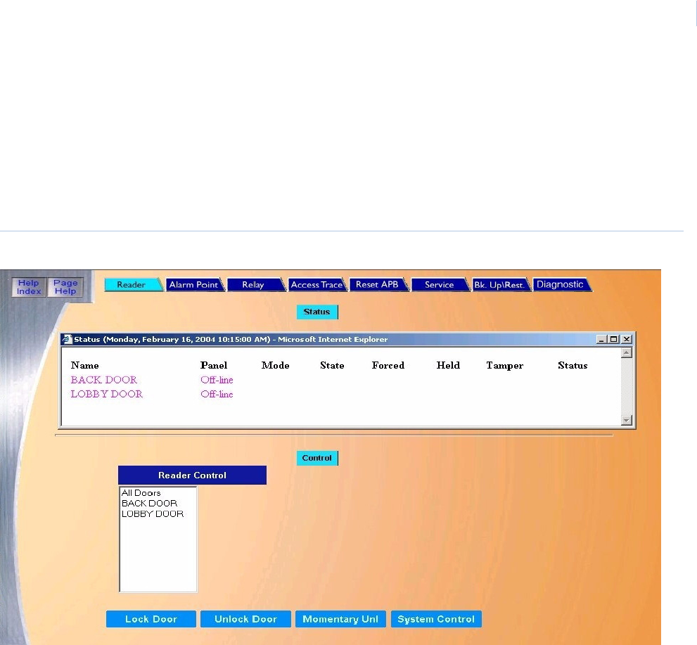
Chapter 5
Control
77
Reader Control Page
The Reader Control page allows you to check the status of any configured reader in the system and
send manual commands to them such as unlock, lock, etc.
To navigate to the Reader Control page, from any page within the Control pages click the Reader
tab button at the top of the screen, or from the main control page click the Reader button on the right
side of the screen. The following page displays.
Figure 60.Reader Control page

Topa z
User Manual
78
The Reader Control page contains the following information:
How to control a Reader
1. To send a command to a Reader, first select one of the pre-defined readers in the bottom
portion of the window in the list under Reader Control. Scroll through the list and click the
name of the Reader to send the command to.
2. Click the desired command button located below the Reader list. The possible commands
that may be sent are System Control, Lock Door, Unlock Door, or Momentary Unlock.
After clicking one of the above, a message “Operation Complete” displays. If the ACU
controller is not communicating with the PC, then the message “Device Offline” displays.
3. Click OK to continue.
The color of the reader name changes in the Status window to reflect the current command
sent.
Status The top portion of the window under Status lists all pre-configured Readers.
To check the status of any Reader, scroll through the list until the name of the Reader is located. The
color of the text shows the status of the reader. The table below defines the meaning of the colors
Black System Control
Red Unlocked
(Not shown) Momentary Unlock
Green Locked
Magenta Offline
Control The Control portion of the window allows you to send commands to one of the pre-defined readers in
the list under Reader Control.
Reader Control To send commands to a reader, select the name from the pre-configured list of readers. Do this by
scrolling through the list and clicking on the desired name.
System Control Places the Reader back to the mode that the door is set for at the current time as predetermined by
the system's configuration.
Lock Door Locks the Reader controlled door. The door remains locked until another command is sent either by
the operator, time schedule, or linked condition, etc. to change the door to another state. It does not
respond to an authorized cardholder.
Unlock Door Unlocks the door. The door remains unlocked until another command is sent either by the operator,
time schedule, etc. to change the door to another state.
Momentary Unlock Unlocks the door. The door remains unlocked for the configured unlock time. At the end of the unlock
time the door returns to its prior state
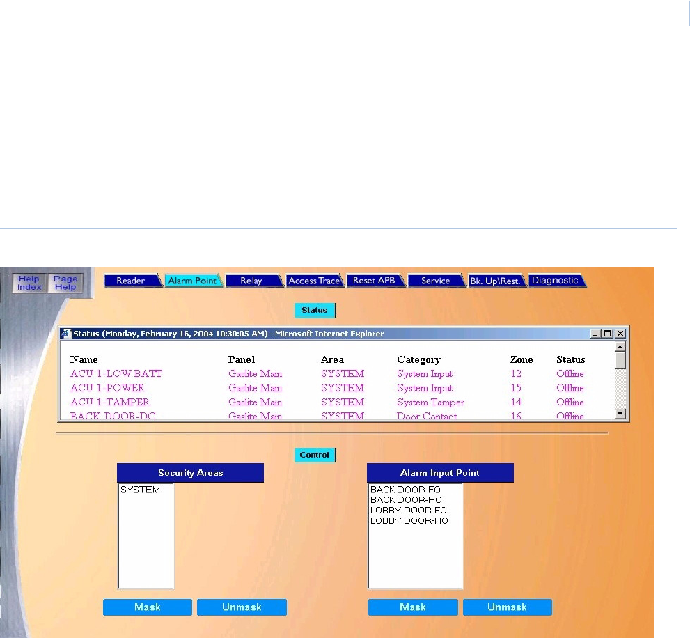
Chapter 5
Control
79
Alarm Point Control Page
The Alarm Point Control page allows you to mask, unmask, or check the status of the Alarm Input
Points and Security Areas.
To navigate to the Alarm Point Control page, from any page within the Control pages click the
Alarm Point tab button at the top of the screen, or from the main control page click the Alarm Point
button on the right side of the screen. The following page displays.
Figure 61.Alarm Point Control page

Topa z
User Manual
80
The Alarm Point Control page contains the following information:
How to Mask/Unmask a Security Area or Alarm Input Point
1. To Mask or Unmask a Security Area or Alarm Input Point, select the name from the pre-
configured list of Security Area names or Alarm Input Point names located in the bottom of
the window under the Control portion of the window. Do this by scrolling through the list and
clicking on the desired name.
2. Click the Mask or Unmask button to mask or unmask the Security Area or Alarm Input Point,
as desired.
After clicking one of the above, a message “Operation Complete” displays. If the ACU
controller is not communicating with the PC, then the message “Device Offline” displays.
3. Click OK to continue.
Status The top portion of the window under Status lists all pre-configured alarm points.
To check the status of any Alarm Point or Security Area scroll through the list until the name of the
Alarm Point or Security Area is located. The color of the name in the list determines its current status.
Blue Masked
Green Secure
Red Alarm
Peach Open
Peach Short
Peach Ground
Peach Circuit Fault
Magenta Offline
Control The Control portion of the window allows you to mask or unmask a Security Area or Alarm Input
Point.
Security Area To Mask or Unmask a Security Area, select the name from the pre-configured list of Security Area
names. Do this by scrolling through the list and clicking on the desired name.
Alarm Input Point To Mask or Unmask an Alarm Input Point, select the name from the pre-configured list of Alarm Input
Point names. Do this by scrolling through the list and clicking on the desired name.
Note: Only the alarm points that were configured as maskable appear in the list.
Mask Click to mask the Security Area or Alarm Input Point, as desired.
Unmask Click to unmask the Security Area or Alarm Input Point, as desired.
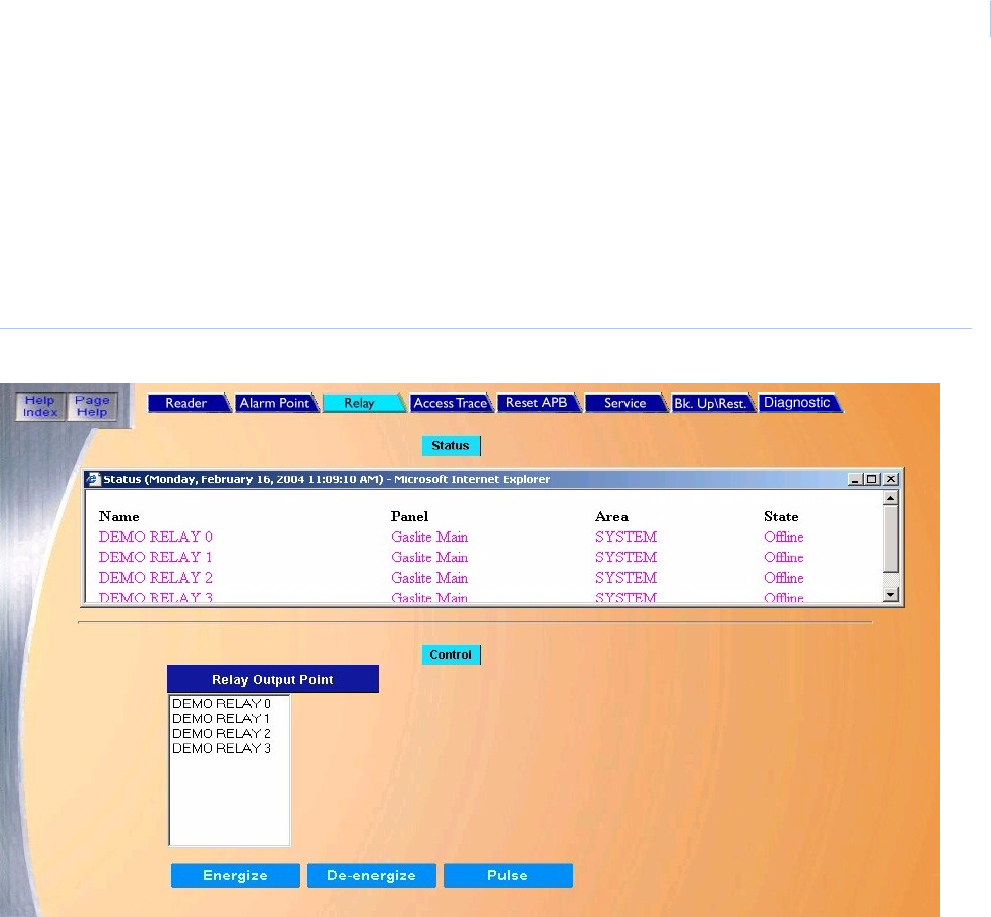
Chapter 5
Control
81
Relay Control Page
The Relay Control page allows you to control and check the status of relays and groups of relays.
Relays are sometimes referred to as Output Points.
To navigate to the Relay Control page, from any page within the Control pages click the Relay tab
button at the top of the screen, or from the main control page click the Relay button on the right side
of the Main Control screen. The following page displays.
Figure 62.Relay Control page

Topa z
User Manual
82
The Relay Control page contains the following information:
How to control or change the status of a Relay Point
1. To control or change the status of a Relay Point, scroll through the list of Relays in the lower
portion of the window under Control.
2. Click the name of the Relay to control.
3. Once the name is selected (highlighted), click the desired function, Energize, De-energize, or
Pulse.
After clicking one of the above, a message “Operation Complete” displays. If the ACU
controller is not communicating with the PC, then the message “Device Offline” displays.
4. Click OK to continue.
Status The top portion of the window under Status lists all pre-configured relays.
To check the status of a Relay, scroll through the Status List in the upper portion of the
window. The color of the name shows its status as follows:
Green De-energized
Red Energized
(Not shown) Pulse Output
Magenta Offline
Control To control or change the status of a Relay Point, scroll through the list of Relay Output
Points.
Relay Output Point Click the name of the Relay to control.
Energize Output This command activates or turns ON the relay until another command is sent by the
operator, time schedule, or linked condition, to change the relay to another condition.
De-energize Output This command de-activates or turns OFF the relay until another command is sent by the
operator, time schedule, or linked condition, to change the relay to another state.
Pulse Output This command activates or turns ON the relay. The relay remains activated or ON for less
than one second and then de-activates.
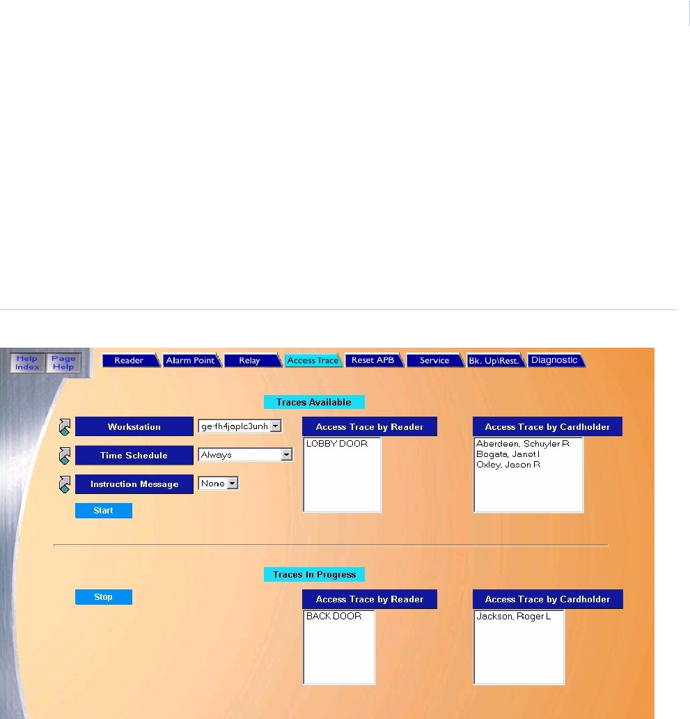
Chapter 5
Control
83
Access Trace Page
The Access Trace page allows you to setup a real time trace for Cardholder(s) or Reader(s). In a
Cardholder trace, the movements of the selected cardholder in and out of access points are
monitored. In a Reader trace, any activity at that reader is reported.
The trace can be configured to be active only during a selected time schedule and can be sent to a
selected workstation PC. An Alarm Instruction Message may also be linked to the trace so that the
message is displayed along with the trace event.
To navigate to the Access Trace page, click the Access Trace tab button at the top of any Control
page, or from the main control page click the Access Trace button on the right side of the screen.
The following page displays.
Figure 63.Access Trace page

Topa z
User Manual
84
The Access Trace page contains the following information:
How to start a Trace
1. To start a trace for a specific or a specific Cardholder or Reader, in the upper portion of the
window under Traces Available, click the Cardholder name or Reader name that you wish to
trace.
2. Once the cardholder name is highlighted, select the desired Workstation, Time Schedule, and
Instruction Message.
3. Click Start to start the trace. The selected Cardholder or Reader is removed from the Traces
Available list and now appears in the Traces In Progress list. A message “Operation
Complete” displays.
How to stop a Trace
1. To stop a trace for a specific Cardholder or Reader, in the lower portion of the window under
Traces In Progress, click the Cardholder name or Reader name that you wish to stop tracing.
2. Once the name is highlighted, click Stop to stop the trace. The selected Cardholder or
Reader name is removed from the Traces In Progress list and appears back in the Traces
Available list.
After clicking one of the above, a message “Operation Complete” displays.
Traces Available The top portion of the main window has two lists, one showing the Readers and one showing
Cardholders. A scrollbar to the right of the list indicates that the list is longer than the window. Use the
scrollbar to view the entire list.
Workstation If a workstation is being used, from the list select the workstation for the trace to report to.
Note: To configure a Workstation, click the link arrow to the left of the field to call up the
Workstation configuration page. When you have completed the configuration, close the
page by clicking Save. You will return to the Access Trace page.
Time Schedule Select the Time Schedule for the trace to be active.
Note: To configure a Time Schedule, click the link arrow to the left of the field to call up the Time
Schedule configuration page. When you have completed the configuration, close the page
by clicking Save. You will return to the Access Trace page.
Instruction Message Select from the drop-down list of pre-configured Instruction Messages the message to be displayed
when the trace event occurs.
Note: To configure an Instruction Message, click the link arrow to the left of the field to call up the
Instruction Messages configuration page. When you have completed the configuration,
close the page by clicking Save. You will return to the Access Trace Page.
Start Once the cardholder name or reader is highlighted and the desired Workstation, Time Schedule, and
Instruction Message have been selected, click Start to start the trace. The selected cardholder or
reader is removed from the Traces Available list and now appears in the Traces In Progress list.
Traces in Progress The lower portion of the main window has two lists of traces that are in progress, one showing the
Readers and one showing Cardholders. A scrollbar to the right of the list indicates that the list is
longer than the window. Use the scrollbar to view the entire list.
Stop Under Traces In Progress, click the Cardholder name or Reader name that you wish to stop tracing.
Once the name is highlighted, click Stop to stop the trace. The selected Cardholder or Reader name
is removed from the Traces In Progress list and appears back in the Traces Available list.
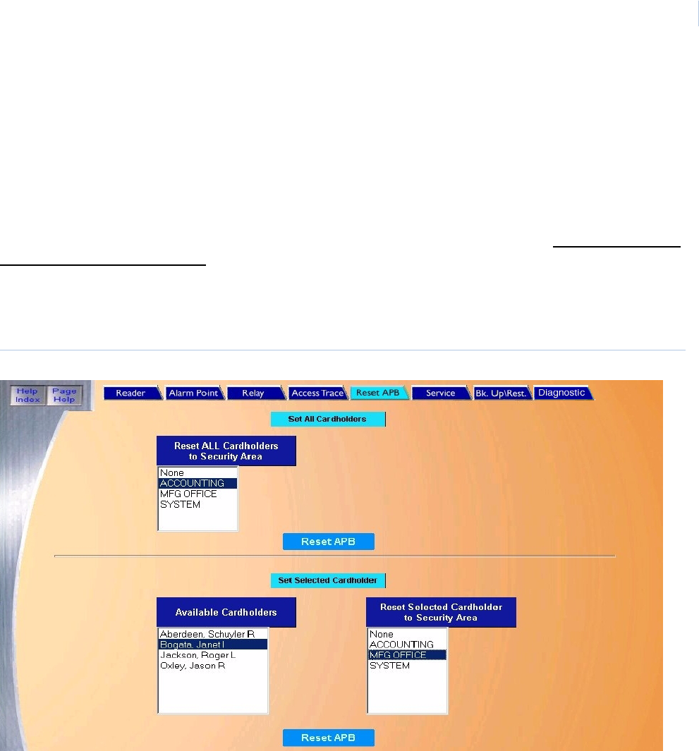
Chapter 5
Control
85
Reset APB Page (Anti-Passback)
The Reset APB page allows you to reset the Anti-Passback status of a cardholder or all cardholders
in a selected Security Area.
Reset APB is used to reset cardholders who have access to the APB Security Area to allow them to
enter that area after they have exited without swiping their cards. For example, if all cardholders who
are in an APB Security Area leave quickly because of a fire and do not swipe their cards individually
upon exiting, the system thinks they are still in the APB area. Reset APB also allows the security
staff to set (change) the Security Area to a different area that is not an APB area for all cardholders
who have access to that area.
To navigate to the Reset APB page, from any page within the Control pages, click the Reset APB
tab button at the top of the screen, or from the main control page click the Reset APB button on the
right side of the screen. The following page displays.
Figure 64.Reset APB page
The Reset APB page contains the following information:
Set All Cardholders Reset cardholders who have exited the APB area without swiping their cards. This allows them
back into the APB area.
Reset ALL Cardholders to
Security Area
From the list, click the name of the Security Area that you wish to reset.
Set Selected Cardholders Reset the APB of only one cardholder at a time to a selected Security Area. This allows the
specified cardholder who has access to the APB Security Area to re-enter that area after
exiting the APB area without swiping their card.
Available Cardholders From the list, click the name of the cardholder that you wish to reset
Reset Selected Cardholders
to Security Area
From the list, click the Security Area to which you wish to reset the selected cardholder.
Reset APB Allow reentry to the selected Security Area of the selected cardholder or all cardholders.

Topa z
User Manual
86
How to reset all cardholders
This is used to reset cardholders who have exited the APB area without swiping their cards. This
allows them back into the APB area.
To reset all cardholders in a selected Security area:
1. Click the name of the Security Area in the Reset ALL Cardholders to Security Area list that
you wish to reset.
2. After the name is highlighted, click Reset APB in the top of the Set All Cardholders section.
A message “Operation Complete” displays.
3. Click OK to continue.
For an overview on Anti-Passback, see Appendix C, Anti-Passback.
How to reset selected cardholders
This function enables you to reset the APB of only one cardholder at a time to a selected Security
Area. This is used to allow the specified cardholder who has access to the APB Security Area to be
allowed to re-enter that area after exiting the APB area without swiping their card.
For example, if a cardholder who is in a specified Security Area left the area by tailgating behind
another cardholder and did not swipe their card upon exiting. The Topaz system thinks the
cardholder is still in that area. This allows the security staff to reset that Security Area to allow reentry
for that one cardholder only.
To reset the selected cardholder to a selected Security Area:
1. Click the Cardholder Name in the Available Cardholders list.
2. Click the Security Area the cardholder is to be reset to.
3. After the Cardholder and Security Area names have been highlighted click Reset APB in the
lower Set Selected Cardholder section.
A message “Operation Complete” displays.
For more information on Anti-Passback, see Appendix C, Anti-Passback.
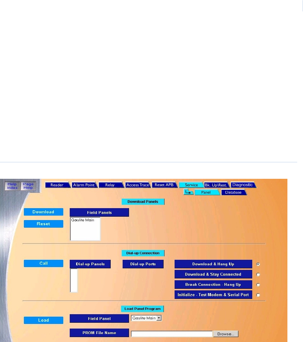
Chapter 5
Control
87
Service
The service tab includes:
Panel Page on page 87
Database Page on page 90
Panel Page
The Panel page allows you to download data to field and dial-up panels and to update panel
firmware.
To navigate to the Panel page, from any page within the Control pages click the Service tab button
at the top of the window, or from the Control page click the Service Function button on the right side
of the screen. The following page displays.
Figure 65.Service: Panel page

Topa z
User Manual
88
The Panel page contains the following information:
How to download data to a selected panel
To download all data to a selected panel:
1. Scroll through the list of pre-configured panels in the Field Panels list and select the panel to
download to by clicking on the name in the list.
2. Once the name is highlighted, click Download located in the Download Panels section to
start the download of all data to the currently selected ACU panel.
A message “Operation Complete” displays.
Note: If the panel fails to download, the panel reverts to the data in the panel before the download was started.
The downloaded data does not take effect until the entire database has been downloaded.
Download Panels This section is used to download all data to a selected panel.
Field Panels Scroll through the list of pre-configured panels in the Field Panels list and select the panel to
download to by clicking on the name in the list.
Download Once the name is highlighted, click to start the download of all data to the currently selected ACU
panel.
Note: If the panel fails to download, the panel reverts to the data in the panel before the
download was started. The downloaded data does not take effect until the entire database
has been downloaded.
Reset If the field panel requires rebooting, select the field panel in the list and click Reset. In most cases
this eliminates the need to respond to the location of the panel to reset it.
Dial-up Connections This section is used when downloading data to a dial-up panel.
Dial-up Panels To download to a dial-up panel, scroll through the list of pre-configured Dial-up Panels and select
the panel to download to by clicking on the name in the list so that it is highlighted.
Dial-up Ports If Initialize - Test Modem & Serial Port is selected, the Dial-up Ports list is available to select the port
to be tested. Select the port before continuing. The Dial-up Panels list is not available for the port
test.
When using dial-up, the modem baud rate should be set to 9600 with no parity. A Robotics
Sportster external modem must be used at the host computer.
Download & Hang Up After the download is completed, the panel hangs up (disconnects).
Download & Stay
Connected
After the download is completed, the panel stays connected (does not hang up).
Break Connection-
Hang Up
This option forces the selected panel in the Dial-up Panels list to hang up (disconnect).
Initialize-Test Modem &
/Serial Port
This option conducts a test of the selected computer's serial port and attached modem selected
from the Dial-up Ports list.
Call Once the panel or port name is highlighted and the option is selected, click to start the requested
communication function.
Load Panel Program This section is used to update firmware on a selected panel.
Field Panel From the Field Panel list, select the panel to update.
PROM File Name Enter the update file name in the field window, or click Browse to locate the update file.
Load Click to start the program loading.

Chapter 5
Control
89
How to download data to a selected panel using a dial-up connection
To download to a dial-up panel:
1. Scroll through the list of pre-configured Dial-up Panels and select the panel to download to by
clicking on the name in the list so that it is highlighted.
2. Next select one of the four download options:
• Download & Hang Up
• Download & Stay Connected
• Break Connection - Hang Up
• Initialize - Test Modem & Serial Port
The desired option can be selected by clicking on the white circle to the right of the
option. This places a small black dot in the circle indicating the option is selected.
3. Once the panel or port name is highlighted and the option is selected, click Call located to the
left of the Dial-up Panels list to start the requested communication function.
A message “Operation Complete” displays.
How to load panel program (firmware updates)
Prerequisite:
Panel firmware versions 7.07.02 and newer require:
• Topaz software version 1.4.6 or later
• Panel firmware version 5.85.00 or later
Note: If the version of your panel firmware is earlier than 5.85.00, you must first upgrade to version 5.85.00 (located in
Topaz CD\Firmware\Beta) and then again to the latest version (located in Topaz CD\firmware\)
1. At the bottom of the screen, in the Load Panel Program section, select the panel you wish to
upgrade from the Field Panel list.
2. In the PROM File Name field, enter the update firmware file name using one of the following
methods:
a. Type the PROM file name. When typing the PROM File Name in the field you must enter
the entire file path, for example, C:\acux070702.s19
b. Click Browse and navigate to the Topaz CD\Firmware\ folder to locate the newest
firmware file. Click Open.
Note: Firmware can only be upgraded from the server. The PROM File can be received in a number of ways,
e.g., floppy disk, E-mail, or CD. Once you receive the file, we recommend that you copy the file to the
hard drive of the server and then reference the updated file from the hard drive. Running an update from
the floppy drive can be VERY slow.
It is also recommended, after updating one panel you check all the features in the updated panel to make
sure that it is functioning properly then continue updating the other panels on your system one at a time.
3. Click Load located to the left of the Field Panels list to start the program loading. A message
“Operation Complete” displays.
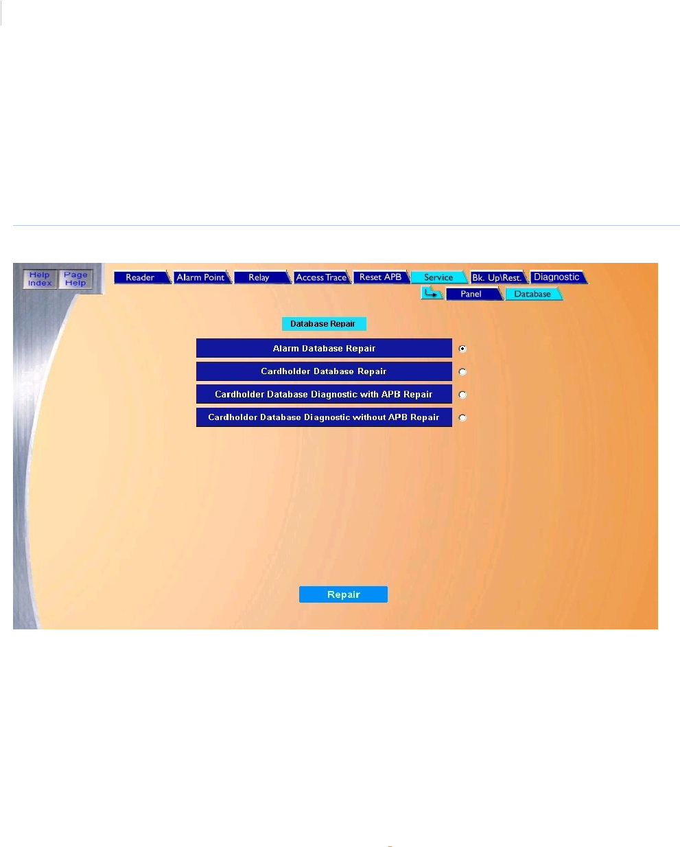
Topa z
User Manual
90
Database Page
The Database page allows you to repair a damaged database.
To navigate to the Database page, from any page within the Control pages, click the Service tab
button at the top of the window and then the Database tab button, or from the Control page click the
Service Function button on the right side of the screen, then the Database tab button. The following
page displays.
Figure 66.Service: Database page
The Database page contains the following information:
Database Repair This page contains various options that allow you to repair a damaged database.
Alarm Database Repair Checks the alarm file for integrity and sends the repaired files to the dms2 folder.
Cardholder Database
Repair
Compares and rebuilds the cardholders file in dms2.
Cardholder Database
Diagnostic with APB
Repair
Checks and repairs the integrity of the Anti-Passback table in the dms1 folder. You do not need to
shut down Topaz.
For an overview on Anti-Passback, see Appendix C, Anti-Passback.
Cardholder Database
Diagnostic without APB
Repair
Checks the integrity of the Anti-Passback table and displays any possible problems. This does not
change the APB status tables. No files are changed.
For more information on Anti-Passback, see Appendix C, Anti-Passback.
Repair After you select the desired repair option, click to start the repair diagnostic procedure.
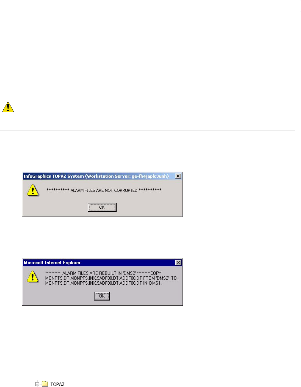
Chapter 5
Control
91
How to execute one of the repair programs
1. To run one or more of the following Database Repair options, click the white button to the
right of the desired option. This places a black dot in the button indicating it has been
selected. Only one option may be selected and executed at a time.
Note: It is highly recommended that you backup your database before performing a database repair. To
backup, go to Control Page – Back Up/Restore.
2. After you select the desired repair option, click Repair to start the repair diagnostic
procedure. An “Operation Complete” message displays.
3. If there were no database errors, a message such as the following displays:
However, if any errors in the database were present, a message displays containing a list
of the files that need to be copied from the dms2 folder to the dms1 folder. For example, if
you had some alarm point errors in the database, a message like the following might
display:
This message tells you which files you have to move (copy).
4. If you get such a message, to finish the database repair, you must do the following:
a. Shut down Topaz.
b. Bring up Windows Explorer.
c. Select the drive and folder where the Topaz software was installed, usually C:\Topaz.
d. Click the plus sign next to the Topaz folder to expand its list of subfolders.
CAUTION: Since running the Alarm Database Repair or the Cardholder Database Repair programs changes files, it
is important that you be experienced and properly trained in using them. In addition, if your site has both a server
and the workstation, it is suggested that the repairs be done at the server. If copying of files is required, the
copying must be done at the server.
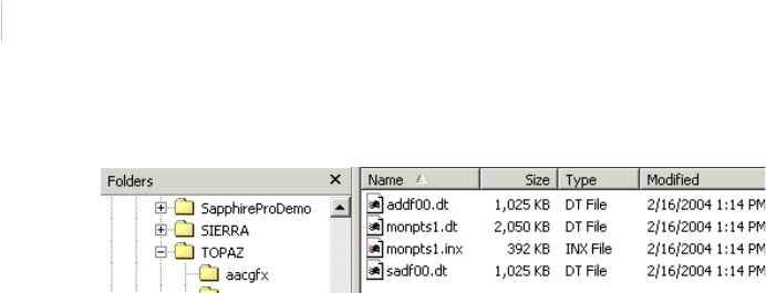
Topa z
User Manual
92
e. Select the dms2 folder. You should see a list of files such as the following:
f. If you do not see a list with filenames and dates as shown above, select View and then
Details.
g. The files listed should correspond to the files in the Topaz message.
h. Double-click the ‘Modified’ title to sort the files by date and time.
i. Select the files with the most current date and time under ‘Modified’ by pressing and
holding the SHIFT key, clicking on the top ‘Name’, then clicking on the last name with that
same date and time. (This is to select only the most recently repaired files).
j. Select Edit and then Cut.
k. Select the dms1 folder to open its folder icon.
l. Select Edit and then Paste.
m. A Windows Confirm File Replace dialog box displays. Select Yes to All.
n. This completes the moving of files from dms2 to dms1. You may now close Windows
Explorer by selecting File and then Close.
o. Restart Topaz.
This completes the database repair(s) you have selected.
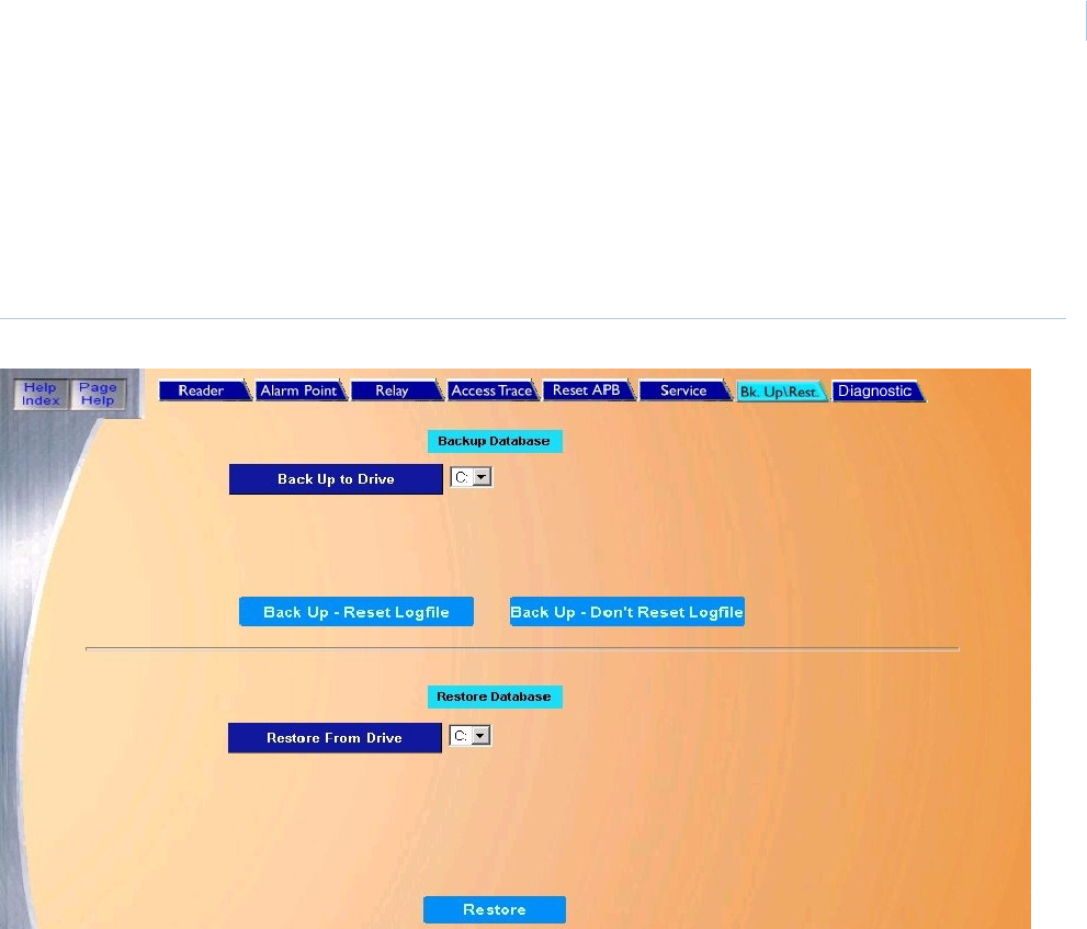
Chapter 5
Control
93
Back Up\Restore Database Page
The Back Up/Restore page allows you to back up and restore programs and data files. To navigate
to the Back Up\Restore page, from any page within the Control pages click the Back Up\Rest. tab
button at the top of the screen, or from the main Control Page click the Back Up\Restore button on
the right side of the screen. The following page displays.
Figure 67.Back Up/Restore page.
The Back Up/Restore page contains the following information:
How to back up your database
We recommend that you back up your database on a regular basis. If you encounter a problem and
need to restore your database, the restoring can only go back as far as your last backup. There are
two options for the backup. Either the Logfile can be Reset allowing new data to be written over the
old data, or the Logfile is not Reset and new data is added to the end of the file.
1. Enter the Drive letter for the location where the files are to be backed up. (Zip, Jaz, etc.).
2. Select one of the following options:
Backup Database The top portion of the page is used to back up data.
Back Up to Drive The Drive letter for the location where the files are to be backed up (Zip, Jaz, etc.).
Back Up-Reset Logfile This option allows new data to be written over the old data.
Back Up-Don’t Reset Logfile This option adds new data to the end of the file.
Restore Database The bottom portion of the page is used to restore data.
Restore From Drive The Drive Letter that the files are restored from (Zip, Jaz, etc.).
Restore After all selections have been made, click to start the restore process.

Topa z
User Manual
94
a. If you want to overwrite the log, click Back Up-Reset Logfile to start the backup process.
b. If you want to append data to the end of the log, click Back Up-Don’t Reset Logfile to
start the backup process.
3. One of the following messages should display:
• If “Operation Complete” is displayed, then no further changes are needed.
• If the message “Operation Failed” is displayed, one of the following has occurred.
• A drive letter was not entered into the drive field.
• The drive was not ready yet. If you are using a zip drive, you may not have a cartridge
inserted.
Check all field selections, make corrections, and try to execute the backup again.
How to restore your database
Note: Because the server must be rebooted, we recommend that the restore be done at the server.
1. Enter the Drive Letter that the files are restored from (Zip, Jaz, etc.).
2. Click Restore located in the Restore Database section to start the restore process. When the
selected file(s) have been restored, a message “Restart the Workstation” displays.
3. Click OK to continue.
Note: The message “Restart the Workstation” displays even if you are restoring from the server.
4. Shutdown and restart Topaz.
Back Up Contents and Logic
The following is a list of folders and files with the use and meaning that the system uses when doing
a backup. These folders are placed by default in the C:\Program Files\GE\Topaz location.
A backup is essentially copying the folders and files above to the root of the location specified. If two
backups are done to the same location, the second backup overrides the first. If the Topaz
application is shutdown and the files from your backup are brought back in, you are essentially
restoring the database. We recommend that you backup to a shared drive, other than the server, so
that if the server goes down, you can restore the database from another location. Backing up to a CD
is only possible if you can do a cut and paste through Windows of the files above to your CDRW
Drive. Several types of CD software make this possible.
CAUTION: Restoring the database requires the system to be rebooted and may interfere with daily activities.
AACGFX Alarm Color Graphic Map files
DMS1 Database. Contains all records from Cardholders to Readers to Alarms and Relays
Badger Contains your Badge Templates, Photos and Signatures
Screens The only file that gets copied from the Screens folder is the sysconfg.dat. The sysconfg contains all
your rights with in the Topaz software as to the maximum number of readers, cardholders etc.
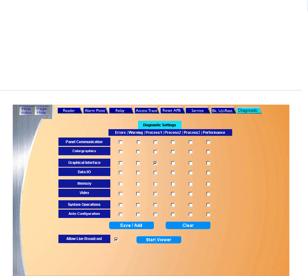
Chapter 5
Control
95
Diagnostic Settings Page
The Diagnostic Settings page allows the operator to define what kind of information about the Topaz
system is recorded. To navigate to the Diagnostic Settings page, from any page within the Control
pages click the Diagnostic tab at the top of the screen, or from the main browser window click on the
Diagnostic button on the right side of the screen. The following page displays.
Figure 68.Diagnostic Settings page
The main portion of the Diagnostic Settings page consists of check boxes arranged in columns,
which represent the level of diagnostic logging requested; and rows, which represent a logical
function to be logged.
The columns function as follows:
• Errors: Checking this column records those items that the software considers a real problem.
For example, ‘File Not Found’ after being requested to get a cardholder’s photo would be an
error.
• Warning: Checking this column records conditions that are less severe than errors, but
indicate unexpected conditions. For example, attempting to take a cardholder photo from a
workstation not authorized for badging functions generates a warning diagnostic message.
• Process1, Process2, Process3: Checking these columns generates diagnostic messages
that record the logic and data as it passes through the system. The least verbose output is
‘Process1,’ the most verbose is ‘Process3.’
• Performance: Checking this column generates performance statistics, such as memory or
network bandwidth usage.

Topa z
User Manual
96
The rows function as follows:
• Panel Communication: Records logic and data involved in communicating with the ACU
panels. This includes such items as regular ‘polls’ sent to the panels, alarms and events
recorded at the panels (readers and various sensors) and reported back to the host, and the
data download that occurs when the panel first connects to the host.
• Color Graphics: Records logic and data associated with the photo badging and map
functions, for example, the search and selection of a camera to be used for photo badging.
• Graphical Interface: Records logic and data associated with the communication with the
operator, for example, input received in response to the operator pressing a ‘save’ key, and
the output data sent to the browser window.
• Data I/O: Records activity associated with the Topaz database, for example, write failures
encounter when a database table is full.
• Memory: Records memory usage and management operations, which can be used to track
memory ‘leaks,’ for example.
• Video: Records logic and activity associated with DVR video integrations, for example,
recording messages exchanged while determining if a DVR is currently online.
• System Operations: records activity not associated with other categories, for example, alarm
or time-zone initiated actions.
• Auto configuration: Records logic and activity associated with the automatic hardware
configuration function.
Enabling any of these options causes diagnostic information to be written to a file on the user’s
system (in the Topaz Server's installation folder) and optionally broadcast in real-time to a Diagnostic
Viewer application. The files are named Diagnostic_log_xx.txt, where ‘xx’ is the hour (0-23) of the
day the data was produced. The files are broken by time to simplify disk management (the files can
grow very large).
Allow Live Broadcast needs to be checked to enable the diagnostic viewer application to receive
real-time broadcasts of diagnostic information. This is a security feature that allows the customer to
block outside parties from observing Topaz operation. The Start Viewer button opens the Diagnostic
Viewer application in a stand-alone window. This application has the ability to view real-time or
archived diagnostic information.
Once your selections have been made, click Save/Add. Clicking the Clear button clears all check
boxes.

This chapter includes information on how to check the status of various
devices in your system.
In this chapter:
Overview. . . . . . . . . . . . . . . . . . . . . . . . . . . . . . . . . . . . . . . . . . . 98
Field Panel Status Page . . . . . . . . . . . . . . . . . . . . . . . . . . . . . . . 99
Reader Status Page . . . . . . . . . . . . . . . . . . . . . . . . . . . . . . . . . 100
Alarm Point Status Page. . . . . . . . . . . . . . . . . . . . . . . . . . . . . . 101
Relay Status Page . . . . . . . . . . . . . . . . . . . . . . . . . . . . . . . . . . 102
Chapter 6 Status
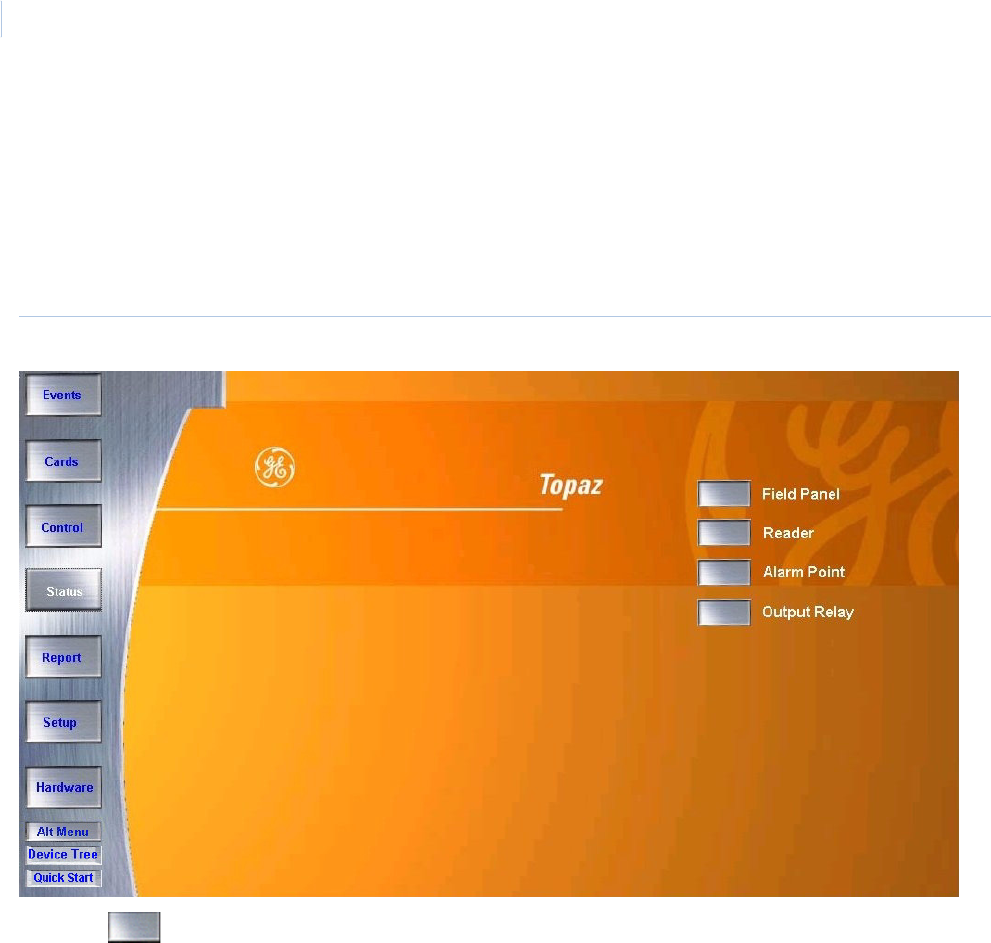
Topa z
User Manual
98
Overview
The Status button allows you to check the status on Field Panels, Readers, Alarm Points, and
Output Relays.
To navigate to the Status page, click the Status button in the left main toolbar. The following screen
displays.
Figure 69.Status page.
Click the button next to the name of the type of device (Field Panel, Reader, etc.) for which you
wish to check the status.
While viewing any one of the status screens, you can refresh the screen by click the tab for the
screen again.
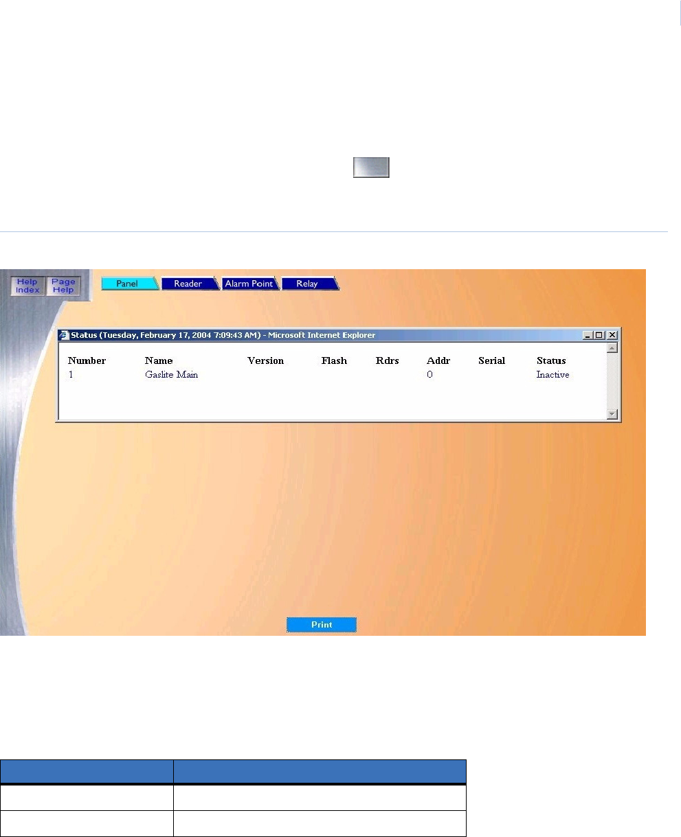
Chapter 6
Status
99
Field Panel Status Page
The Field Panel Status page allows you to check the status of any configured Field Panel (SCP
Device) in the system.
To navigate to the Field Panel Status page click the button next to Field Panel on the main
Status page, or click the Panel tab button at the top of the window while in any Status page. The
following page displays.
Figure 70.Field Panel Status page
To check the status of a panel, scroll through the list of pre-configured panels until the name of the
desired panel appears in the list.
The color of the text for the panel shows the status of the panel. The color definitions are listed
below.
Note: The status of the panel may also be checked on the Panel Control page.
If you want to print the contents of the Status window, click Print.
Table 3. Field Panel Status colors
Color Status
Black Panel Online
Magenta Panel Offline
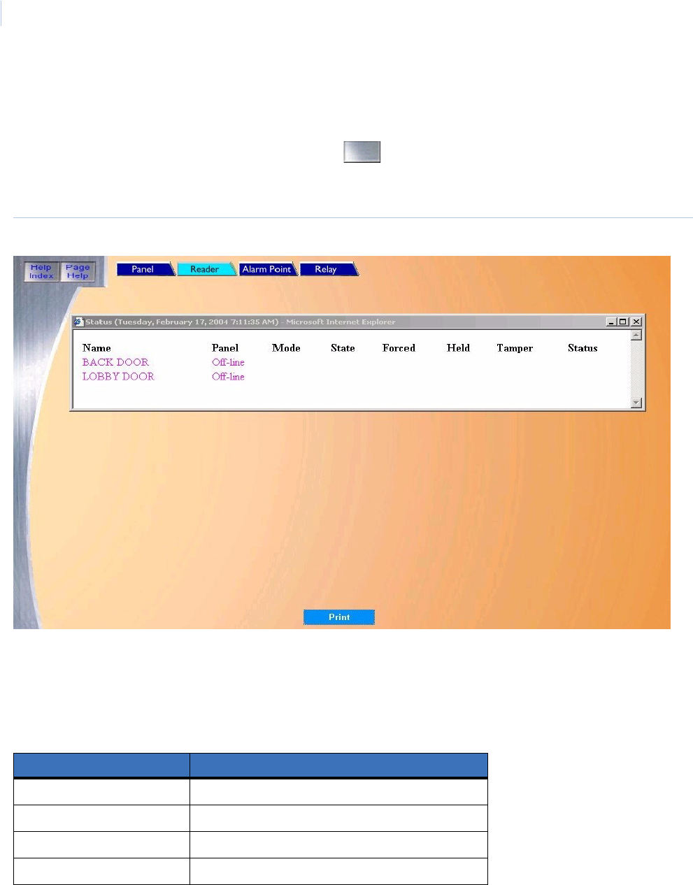
Topa z
User Manual
100
Reader Status Page
The Reader Status page allows you to check the status of any configured reader in the system.
To navigate to the Reader Status page click the button next to Reader on the main Status
page or click the Reader tab button at the top of the window while in any Status page. The following
page displays.
Figure 71.Reader Status page
To check the status of a reader, scroll through the list of configured readers until the name of the
reader appears in the list.
The color of the text for the reader name shows the status of the reader. The color definitions are
listed below.
Note: The status of readers may also be checked on the Control / Reader page.
If you want to print the contents of the Status window, click Print.
Table 4. Reader Status colors
Color Status
Black System Control
Red Unlocked
(Not shown) Momentary Unlock
Green Locked
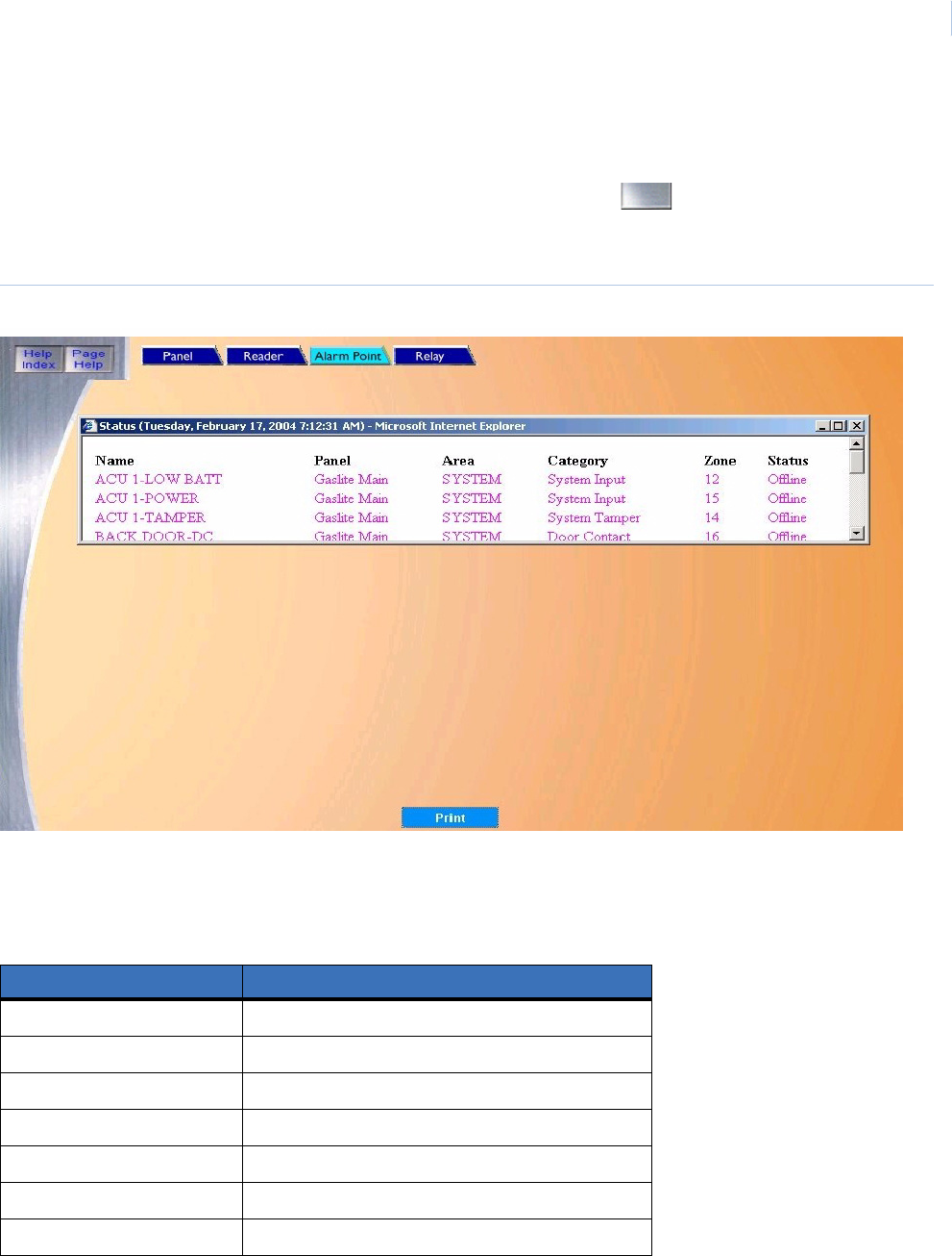
Chapter 6
Status
101
Alarm Point Status Page
The Alarm Point Status page allows you to check the status of any configured Alarm Point in the
Topaz system. To navigate to the Alarm Point status page click the button next to Alarm Point
on the main Status page or click the Alarm Point tab button at the top of the window while in any
Status page. The following page displays.
Figure 72.Alarm Point Status page
To check the status of an alarm point, scroll through the list of configured alarm points until the name
of the alarm point you are looking for appears in the list. The color of the text for the alarm point
name shows the status of the alarm point. The color definitions are listed below.
Note: The status of Alarms may also be checked on the Control / Alarm Point page.
If you want to print the contents of the Status window, click Print.
Table 5. Reader status colors
Color Status
Blue Masked
Green Secure
Red Alarm
Peach Open
Peach Short
Peach Ground
Peach Circuit Fault
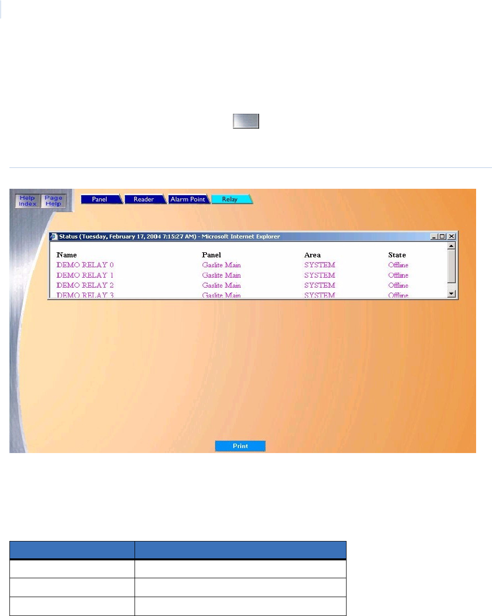
Topa z
User Manual
102
Relay Status Page
The Relay Status page allows you to check the status of any configured output relay in the Topaz
system.
To navigate to the Relay Status page click the button next to Output Relay on the main Status
page or click the Relay tab button at the top of the window while in any Status page. The following
page displays.
Figure 73.Relay Status page
To check the status of an output relay, scroll through the list of pre-configured output relays until the
name of the output relay you are looking for appears in the list.
The color of the text for the output relay name shows the status of the relay. The color definitions are
listed below.
Note: The status of relays may also be checked on the Control / Relay page.
If you want to print the contents of the Status window, click Print.
Table 6. Relay Status colors
Color Status
Black De-Energize
Red Energize
(Not shown) Pulse Output

This chapter includes information on reports available within the system.
In this chapter:
Overview. . . . . . . . . . . . . . . . . . . . . . . . . . . . . . . . . . . . . . . . . . 104
Cardholder Database Reports Page. . . . . . . . . . . . . . . . . . . . . 105
System Setup Report Page . . . . . . . . . . . . . . . . . . . . . . . . . . . 107
Recall Event Reports Page. . . . . . . . . . . . . . . . . . . . . . . . . . . . 134
Alarm History Reports Page . . . . . . . . . . . . . . . . . . . . . . . . . . . 152
Employee Reports Page. . . . . . . . . . . . . . . . . . . . . . . . . . . . . . 156
Chapter 7 Reports
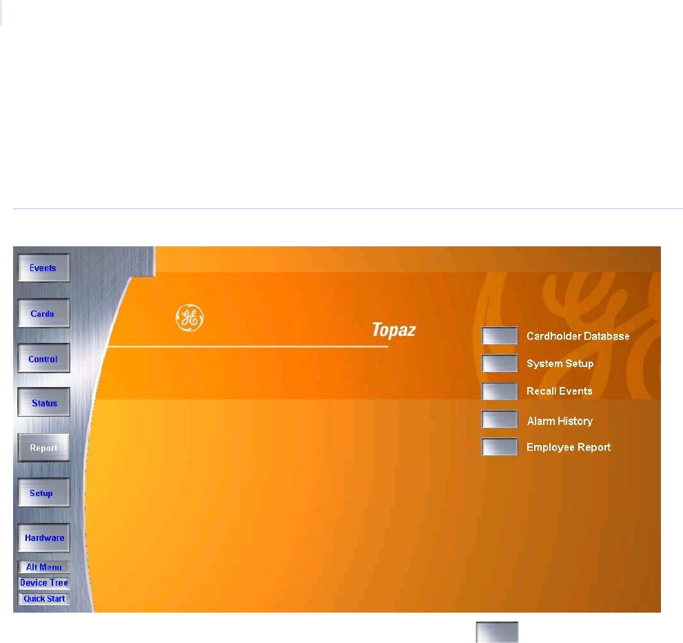
Topa z
User Manual
104
Overview
A large selection of reports is available within the Reports pages that can provide administrators with
a display or printouts on cardholders, employees, events, alarms, and system configuration.
To navigate to the Reports pages, click the Report button in the main navigation toolbar at the left
side of the browser screen. The following screen displays.
Figure 74.Reports: Browser screen
Navigate to the desired reports type by clicking on the corresponding Navigation button next
to the report type desired.
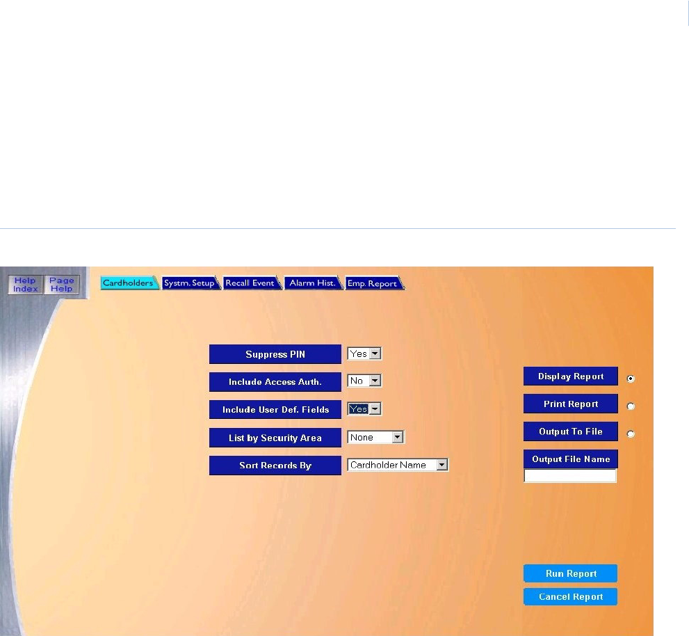
Chapter 7
Reports
105
Cardholder Database Reports Page
The Cardholder Database Reports page can output a wide range of information on any cardholder
in the system. You can select a variety of options to customize the report.
To navigate to the Cardholder Database Reports page, from any page within the Reports pages
click the Cardholders tab button at the top of the window, or from the main Reports page click the
Cardholder Database button on the right side of the screen. The following page displays.
Figure 75.Cardholders
The Cardholders page contains the following information:
Suppress PIN (Yes/
No)
Select Yes if the report is to suppress the cardholder's PIN number (default is Yes). If Yes is selected,
the PIN is not shown on the report.
Include Access Auth.
(Yes/No)
Select Yes if the report is to include access authorization (default is No). If Yes is selected, the
Security Areas the cardholder is authorized for are shown on the report.
Include User Def
Fields (Yes/No)
Select No if the Custom Fields are not included in the report (default is No). If the additional custom
fields should be in the report, change this to Yes.
List by Security Area Select the Security Area from the list that you wish the cardholders to be recalled for. Only
cardholders who are authorized for the selected area are included in the report.
Sort Records By Select how the report is to sort the data. Only one of the four options can be selected:
• Cardholder Number - Cardholder is reported in order of Card Numbers.
• Cardholder Name - Cardholder is reported in order of Cardholder Name.
• Employee Number - Cardholder is reported in order of Employee number.
• Card Serial Number - Cardholder is reported in order of Card Serial Numbers.
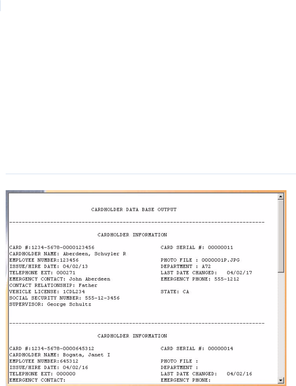
Topa z
User Manual
106
Figure 76.Cardholder report
Output Report There are three ways to output the report.
• Display Report (default) - Displays on the Workstation monitor.
• Print Report – Is sent to the report printer.
• Output To File -Saves the report into the file name specified in the Output File Name field. This
saves the report results in a file for later use outside of Topaz.
Select one of the above output options by clicking the white dot to the right of the selection. This
places a black dot inside the white one activating the selection.
Output File Name If you selected Output to File, enter the name of the file to contain the report information. The Output
File Name can be up to 64 characters with no punctuation or spaces. For example, you can type
“Myreport” and the report is saved into the file named Myreport in the directory where Topaz was
installed. The format of the report files is always plain text and can be opened in Notepad.
Run Report To send the report to the destination you specified above (display, printer, or file), click Run Report in
the bottom right corner of the page.
A message “Report Completed” displays, with the number of records printed. Click OK to continue.
Cancel Report To stop the report or when you have finished viewing the report on the monitor, click Cancel Report.
This cancels the operation and return to the report screen. If no report displays and you click Cancel,
it returns to the Reports page.
A report for one typical cardholder is shown in Figure 76, Cardholder report.
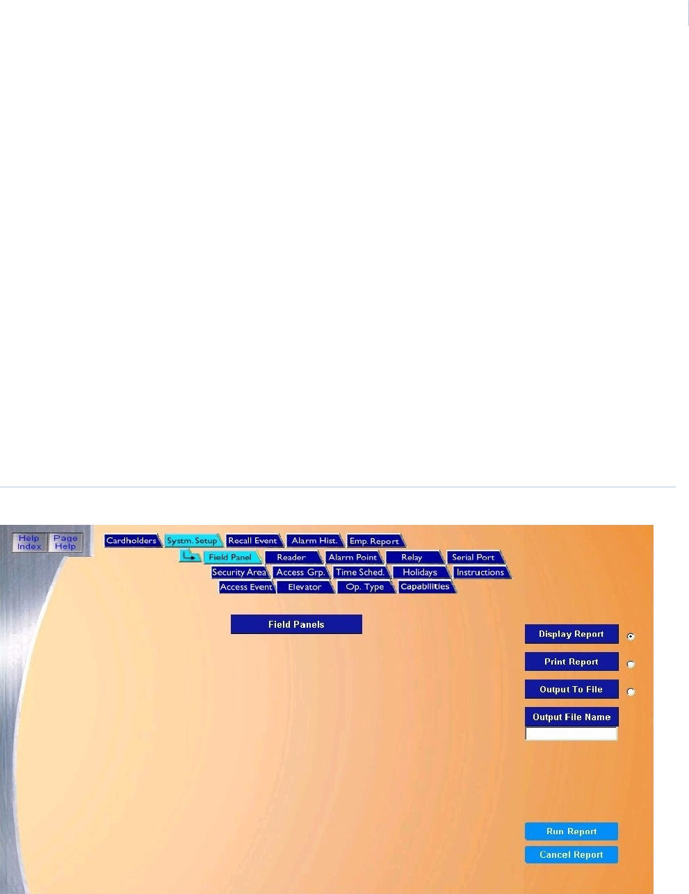
Chapter 7
Reports
107
System Setup Report Page
This group of reports provides all information on how a particular site is configured. After the system
has been configured and all data is entered, you can run reports, and generate lists on each of the
setup items.
Field Panel Setup Report on page 108
Reader Setup Report on page 110
Alarm Point Setup Report on page 112
Relay Setup Report on page 114
Serial Port Setup Report on page 116
Security Area Setup Report on page 118
Access Groups Setup Report on page 120
Time Schedule Setup Report on page 122
Holiday Setup Report on page 124
Instruction Message Setup Report on page 125
Access Event Reporting Options Setup Report
on page 127
Elevator Control Setup Report on page 129
Operator Type Report on page 130
Capabilities Report on page 132
To navigate to the System Setup Report page, from any page within the Reports pages click the
System Setup tab button at the top of the page, or from the main Reports page click the System
Setup button on the right side of the screen. The following page displays.
Note: The Field Panel page displays as the default.
Figure 77.System Setup
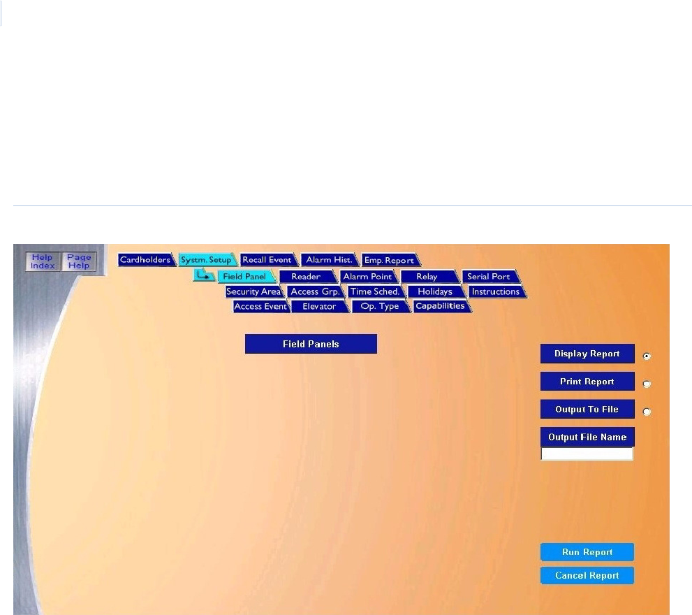
Topa z
User Manual
108
Field Panel Setup Report
The Field Panel Setup Report provides all information on how the field panels are configured/set up
in the system.
To navigate to the Field Panel Setup Report page, from any page within the Reports pages click
the System Setup tab button in the top navigation bar. The following page displays.
Figure 78.System Setup: Field Panel
The Field Panels page contains the following information:
Field Panels The report lists all configured field panels.
Display Report This is the default. Click to display on the Workstation monitor.
Print Report Click to send to the report printer.
Output To File Click to save the report into the file name specified in the Output File Name field. This saves the
report results in a file for later use outside of Topaz.
Output File Name If you selected Output to File, enter the name of the file to contain the report information. The Output
File Name can have up to 64 characters. For example, you can type “Myreport” and the report is
saved into the file named Myreport in the directory where Topaz was installed. You may enter a path
with the file name, for example, “c:\reports\Myreport”. The format of the report files is always plain text
that can be opened in Notepad.
Run Report Click to send the report to the destination specified (display, printer, or file). A message “Report
Completed” displays with the number of records printed. Click OK to continue.
Cancel Report Click to stop the report or when you have finished viewing the report on the monitor. This cancels the
operation and returns to the report screen. If no report displays and you click Cancel, it returns to the
Reports page.
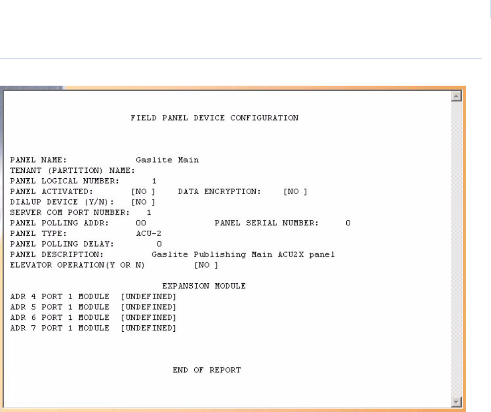
Chapter 7
Reports
109
Figure 79.Reports page
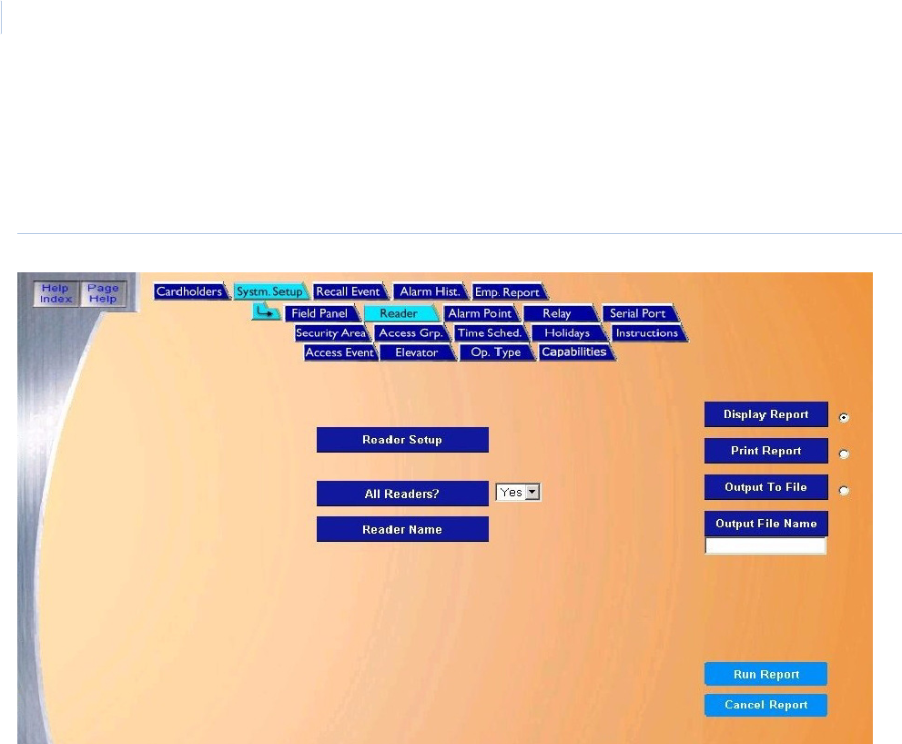
Topa z
User Manual
110
Reader Setup Report
The Reader Setup Report provides all information on how the readers are configured/set up. To
navigate to the Reader Setup Report page, from any page within the System Setup report pages
click the Reader tab button in the top navigation bar. The following page displays.
Figure 80.System Setup: Reader
The Reader page contains the following information:
Reader Setup The Reader Setup report provides all information on how the readers are configured/set up in the system.
All Readers? If Yes is selected, all readers are listed on the report. If No is selected, then a reader must be selected
from the drop-down list under Reader Name.
Reader Name From the drop-down list of pre-configured readers, scroll through and select the reader to be recalled in
the report by clicking on the Reader Name.
Display Report This is the default. Click to display on the Workstation monitor.
Print Report Click to send to the report printer.
Output To File Click to save the report into the file name specified in the Output File Name field. This saves the report
results in a file for later use outside of Topaz.
Output File NameIf you selected Output to File, enter the name of the file to contain the report information. The Output File
Name can have up to 64 characters. For example, you can type “Myreport” and the report is saved into
the file named Myreport in the directory where Topaz was installed. You may enter a path with the file
name, for example, “c:\reports\Myreport”. The format of the report files is always plain text that can be
opened in Notepad.
Run Report Click to send the report to the destination specified (display, printer, or file). A message “Report
Completed” displays, with the number of records printed. Click OK to continue.
Cancel Report Click to stop the report or when you have finished viewing the report on the monitor. This cancels the
operation and returns to the report screen. If no report displays and you click Cancel, it returns to the
Reports page.
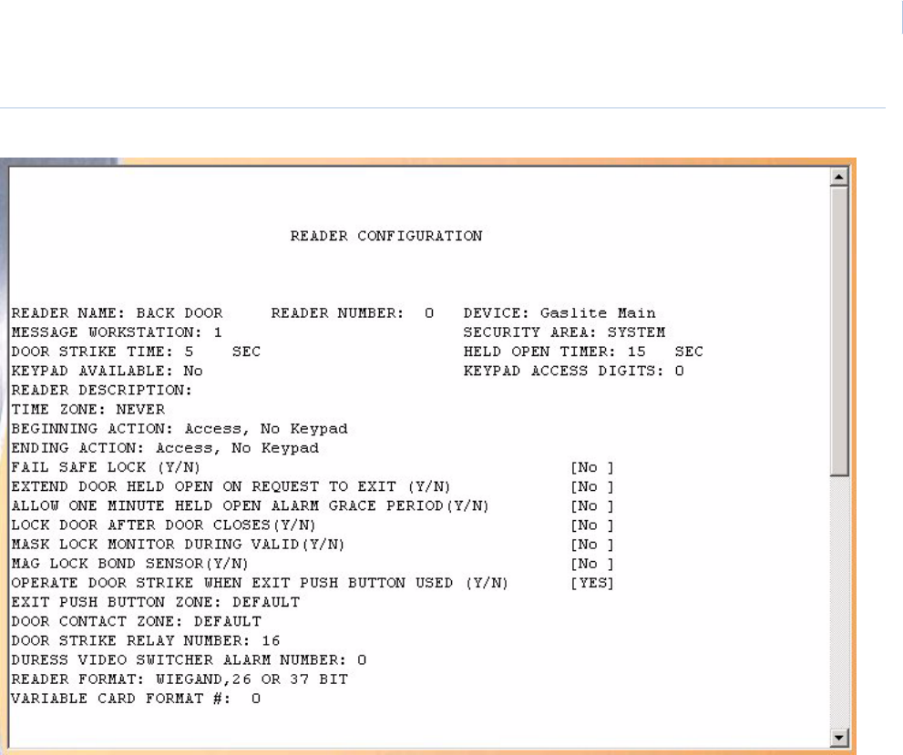
Chapter 7
Reports
111
Figure 81.Sample Reader Setup report
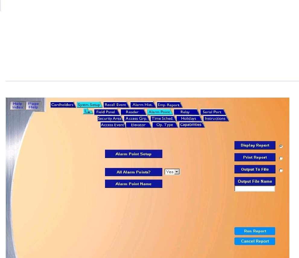
Topa z
User Manual
112
Alarm Point Setup Report
The Alarm Point Setup Report tells how Alarm Points are configured/setup in the system.
To navigate to the Alarm Point Setup Report page, from any page within the System Setup pages
click the Alarm Point tab button in the top navigation bar. The System Setup report page displays.
Figure 82.System Setup: Alarm Point
The Alarm Point page contains the following information:
Alarm Point Setup This report provides all information on how alarm points are configured/set up in the system.
All Alarm Points? If Yes is selected, all alarm points are listed on the report. If No is selected, then an alarm point must
be selected from the drop-down list under Alarm Point Name.
Alarm Point Name From the drop-down list of pre-configured alarm points, scroll through and select the alarm point to be
recalled in the report by clicking on the Alarm Point Name.
Display Report This is the default. Click to display on the Workstation monitor.
Print Report Click to send to the report printer.
Output To File Click to save the report into the file name specified in the Output File Name field. This saves the
report results in a file for later use outside of Topaz.
Output File Name If you selected Output to File, enter the name of the file to contain the report information. The Output
File Name can have up to 64 characters. For example, you can type “Myreport” and the report is
saved into the file named Myreport in the directory where Topaz was installed. You may enter a path
with the file name, for example, “c:\reports\Myreport”. The format of the report files is always plain text
that can be opened in Notepad.
Run Report Click to send the report to the destination specified (display, printer, or file). A message “Report
Completed” displays, with the number of records printed. Click OK to continue.
Cancel Report Click to stop the report or when you have finished viewing the report on the monitor. This cancels the
operation and return to the report screen. If no report displays and you click Cancel, it returns to the
Reports page.
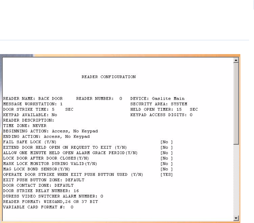
Chapter 7
Reports
113
Below is a sample of part of a displayed report for Alarm Point Setup.
Figure 83.Sample Alarm Point Setup Report

Topa z
User Manual
114
Relay Setup Report
The Relay Setup Report tells how relays are configured/setup in the system.
To navigate to the Relay Setup Report page, from any page within the System Setup pages click
the Relay tab button in the top navigation bar. The following page displays.
Figure 84.System Setup: Relay
The Relay page contains the following information:
Below is a sample of part of a displayed report for Relay Setup.
Relay Setup The Relay Setup report lists all configured relays.
Display Report This is the default. Click to display on the Workstation monitor.
Print Report Click to send to the report printer.
Output To File Click to save the report into the file name specified in the Output File Name field. This saves the
report results in a file for later use outside of Topaz.
Output File Name If you selected Output to File, enter the name of the file to contain the report information. The Output
File Name can have up to 64 characters. For example, you can type “Myreport” and the report is
saved into the file named Myreport in the directory where Topaz was installed. You may enter a path
with the file name, for example, “c:\reports\Myreport”. The format of the report files is always plain text
that can be opened in Notepad.
Run Report Click to send the report to the destination specified (display, printer, or file). A message “Report
Completed displays, with the number of records printed. Click OK to continue.
Cancel Report Click to stop the report or when you have finished viewing the report on the monitor. This cancels the
operation and returns to the report screen. If no report displays and you click Cancel, it returns to the
Reports page.
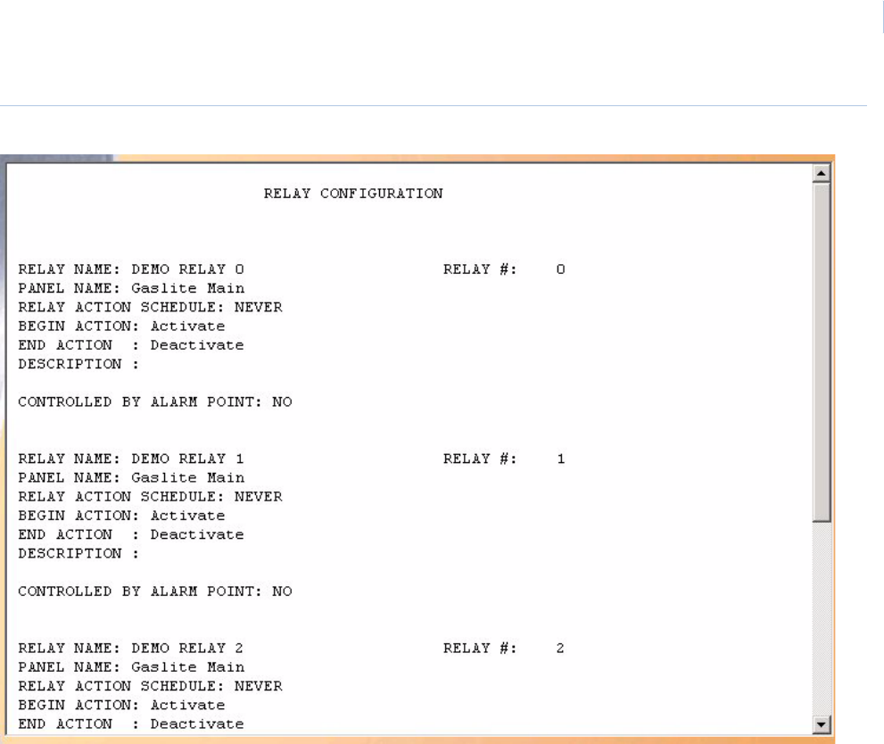
Chapter 7
Reports
115
Figure 85.Sample Relay Setup report
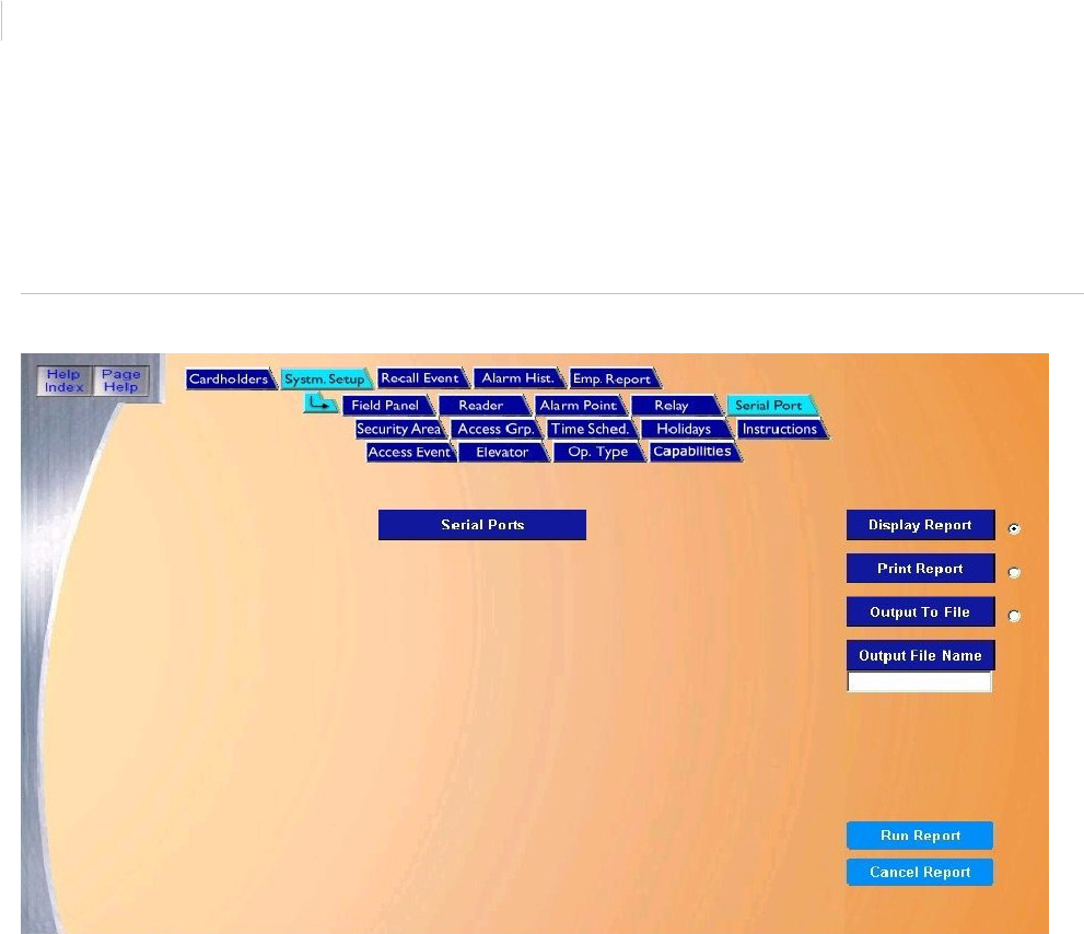
Topa z
User Manual
116
Serial Port Setup Report
The Serial Port Setup Report recalls how Serial Ports are configured/setup in the system.
To navigate to the Serial Port Setup Report page, from any page within the System Setup pages
click the Serial Port tab button in the top navigation bar. The following page displays.
Figure 86.System Setup: Serial Port
The Serial Port page contains the following information:
Below is a sample of a displayed report for Serial Port Setup.
Serial Ports The Serial Port report lists all configured serial ports.
Display Report This is the default. Click to display on the Workstation monitor.
Print Report Click to send to the report printer.
Output To File Click to save the report into the file name specified in the Output File Name field. This saves the
report results in a file for later use outside of Topaz.
Output File Name If you selected Output to File, enter the name of the file to contain the report information. The Output
File Name can have up to 64 characters. For example, you can type “Myreport” and the report is
saved into the file named Myreport in the directory where Topaz was installed. You may enter a path
with the file name, for example, “c:\reports\Myreport”. The format of the report files is always plain
text that can be opened in Notepad.
Run Report Click to send the report to the destination specified (display, printer, or file). A message “Report
Completed” displays, with the number of records printed. Click OK to continue.
Cancel Report Click to stop the report or when you have finished viewing the report on the monitor. This cancels the
operation and return to the report screen. If no report displays and you click Cancel, it returns to the
Reports page.
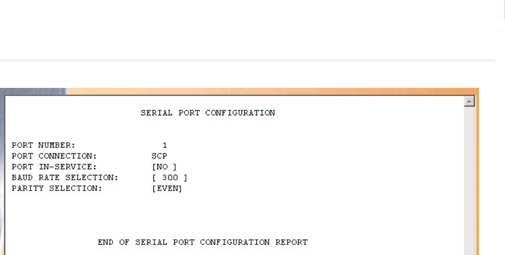
Chapter 7
Reports
117
Figure 87.Sample Serial Port Setup report
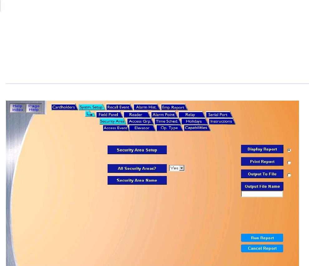
Topa z
User Manual
118
Security Area Setup Report
The Security Area Setup Report recalls how Security Areas have been setup.
To navigate to the Security Area Setup Report page, from any page within the System Setup
pages click the Security Area tab button in the top navigation bar. The following page displays.
Figure 88.System Setup: Security Area
The Security Area page contains the following information:
Security Area Setup The Security Area Setup report recalls how Security Areas have been setup.
All Security Areas? If Yes is selected, all security areas are listed on the report. If No is selected, then a security area
must be selected from the drop-down list under Security Area Name.
Security Area Name From the drop-down list of pre-configured alarm points, scroll through and select the security area to
be recalled in the report by clicking on the Security Area Name.
Display Report This is the default. Click to display on the Workstation monitor.
Print Report Click to send to the report printer.
Output To File Click to save the report into the file name specified in the Output File Name field. This saves the
report results in a file for later use outside of Topaz.
Output File Name If you selected Output to File, enter the name of the file to contain the report information. The Output
File Name can have up to 64 characters. For example, you can type “Myreport” and the report is
saved into the file named Myreport in the directory where Topaz was installed. You may enter a path
with the file name, for example, “c:\reports\Myreport”. The format of the report files is always plain text
that can be opened in Notepad.
Run Report Click to send the report to the destination specified (display, printer, or file). A message “Report
Completed” displays, with the number of records printed. Click OK to continue.
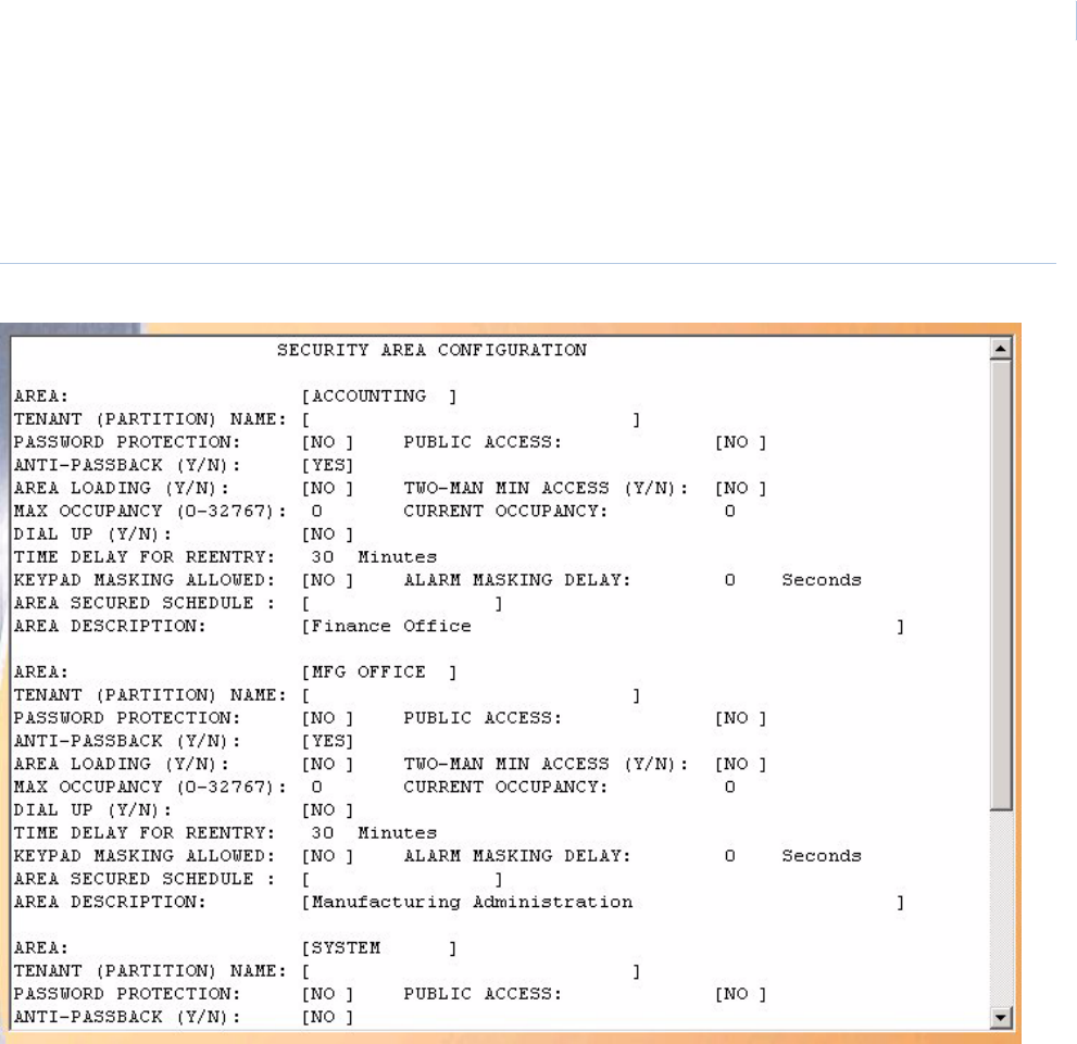
Chapter 7
Reports
119
Below is a sample of a displayed report for Security Area setup.
Figure 89.Sample Security Area Setup report
Cancel Report Click to stop the report or when you have finished viewing the report on the monitor. This cancels the
operation and returns to the report screen. If no report is displaying and you click Cancel, it returns to
the Reports page.
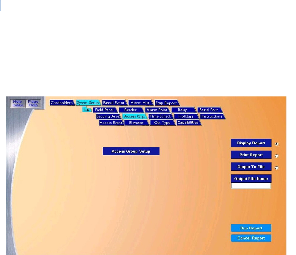
Topa z
User Manual
120
Access Groups Setup Report
The Access Group Setup Report recalls how Access Groups have been setup.
To navigate to the Access Group Setup Report page, from any page within the System Setup
pages click the Access Grp. tab button in the top navigation bar. The following page displays.
Figure 90.System Setup: Access Group
The Access Group page contains the following information:
Below is a sample of a displayed report for Access Group Setup.
Access Group Setup The Access Group Setup report recalls how Access Groups have been set up. The report lists all
access groups.
Display Report This is the default. Click to display on the Workstation monitor.
Print Report Click to send to the report printer.
Output To File Click to save the report into the file name specified in the Output File Name field. This saves the
report results in a file for later use outside of Topaz.
Output File Name If you selected Output to File, enter the name of the file to contain the report information. The Output
File Name can have up to 64 characters. For example, you can type “Myreport” and the report is
saved into the file named Myreport in the directory where Topaz was installed. You may enter a path
with the file name, for example, “c:\reports\Myreport”. The format of the report files is always plain text
that can be opened in Notepad.
Run Report Click to send the report to the destination specified (display, printer, or file). A message “Report
Completed” displays, with the number of records printed. Click OK to continue.
Cancel Report Click to stop the report or when you have finished viewing the report on the monitor. This cancels the
operation and returns to the report screen. If no report displays and you click Cancel, it returns to the
Reports page.
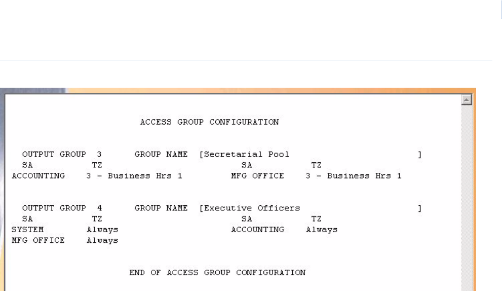
Chapter 7
Reports
121
Figure 91.Sample Access Group Setup report
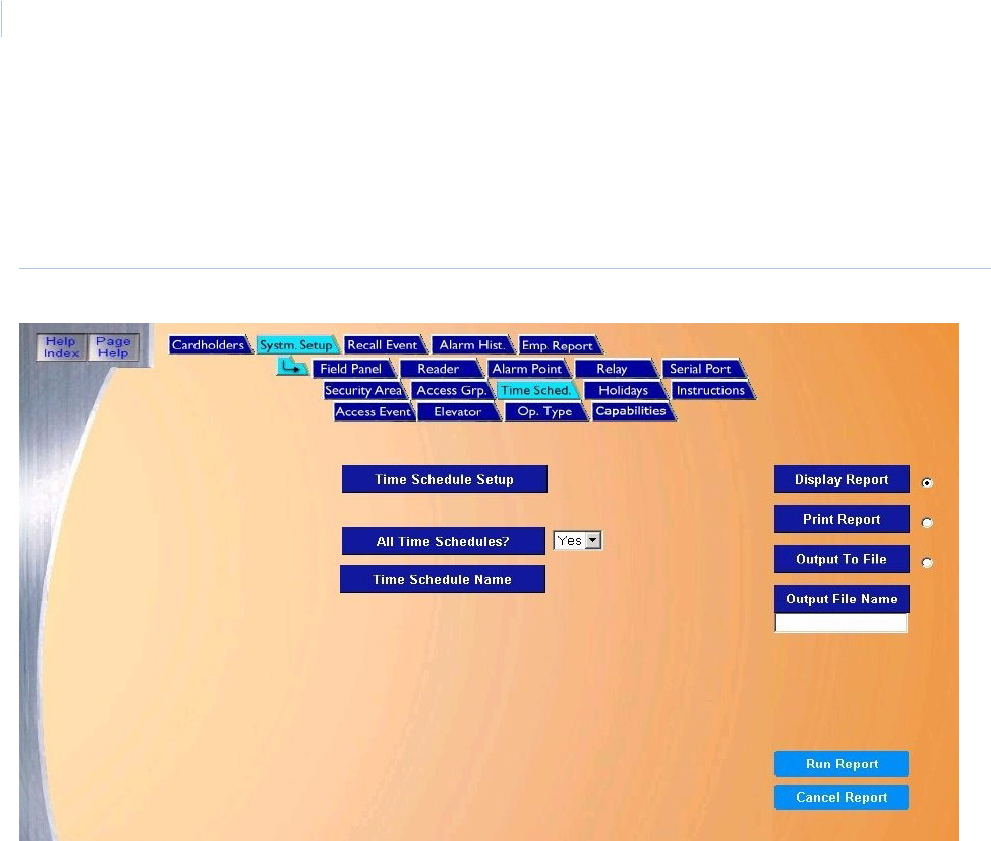
Topa z
User Manual
122
Time Schedule Setup Report
The Time Schedule Setup Report recalls how Time Schedules have been setup.
To navigate to the Time Schedule Setup Report page, from any page within the System Setup
pages click the Time Sched. tab button in the top navigation bar. The following page displays.
Figure 92.System Setup: Time Schedule
The Time Schedule page contains the following information:
Time Schedule SetupThe Time Schedule Setup report recalls how Time Schedules have been setup.
All Time Schedules? If Yes is selected, all security areas are listed on the report. If No is selected, then a Time Schedule
must be selected from the drop-down list under Time Schedule Name.
Time Schedule NameFrom the drop-down list of pre-configured alarm points, scroll through and select the Time Schedule
to be recalled in the report by clicking on the Time Schedule Name.
Display Report This is the default. Click to display on the Workstation monitor.
Print Report Click to send to the report printer.
Output To File Click to save the report into the file name specified in the Output File Name field. This saves the
report results in a file for later use outside of Topaz.
Output File Name If you selected Output to File, enter the name of the file to contain the report information. The Output
File Name can have up to 64 characters. For example, you can type “Myreport” and the report is
saved into the file named Myreport in the directory where Topaz was installed. You may enter a path
with the file name, for example, “c:\reports\Myreport”. The format of the report files is always plain text
that can be opened in Notepad.
Run Report Click to send the report to the destination specified (display, printer, or file). A message “Report
Completed” displays, with the number of records printed. Click OK to continue.
Cancel Report Click to stop the report or when you have finished viewing the report on the monitor. This cancels the
operation and returns to the report screen. If no report displays and you click Cancel, it returns to the
Reports page.
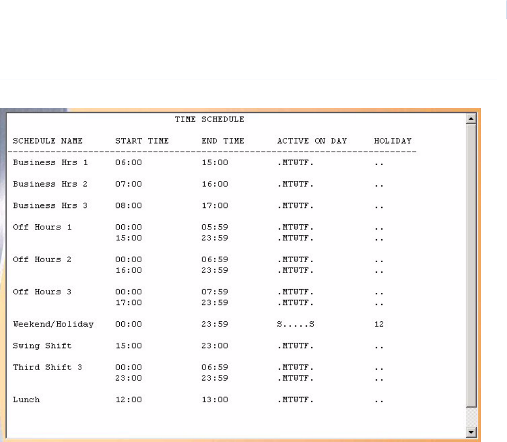
Chapter 7
Reports
123
Below is a sample of part of a displayed report for Time Schedule setup.
Figure 93.Sample Time Schedule Setup report
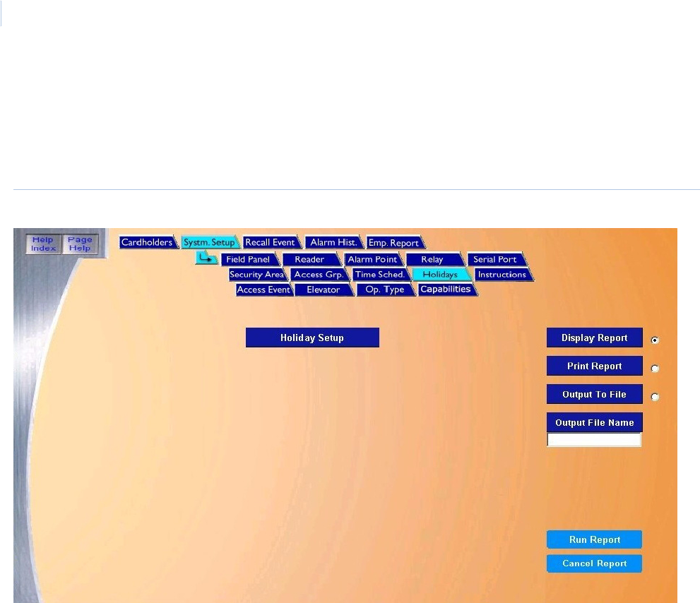
Topa z
User Manual
124
Holiday Setup Report
The Holiday Setup Report recalls how Holidays have been setup.
To navigate to the Holiday Setup Report page, from any page within the System Setup pages click
the Holiday tab button in the top navigation bar. The following page displays.
Figure 94.System Setup: Holidays
The Holidays page contains the following information:
Below is a sample of part of a displayed report for Holiday setup.
Holiday Setup The Holiday Setup report recalls how holidays have been set up. The report lists all configured
holidays.
Display Report This is the default. Click to display on the Workstation monitor.
Print Report Click to send to the report printer.
Output To File Click to save the report into the file name specified in the Output File Name field. This saves the
report results in a file for later use outside of Topaz.
Output File Name If you selected Output to File, enter the name of the file to contain the report information. The Output
File Name can have up to 64 characters. For example, you can type “Myreport” and the report is
saved into the file named Myreport in the directory where Topaz was installed. You may enter a path
with the file name, for example, “c:\reports\Myreport”. The format of the report files is always plain text
that can be opened in Notepad.
Run Report Click to send the report to the destination specified (display, printer, or file). A message “Report
Completed” displays, with the number of records printed. Click OK to continue.
Cancel Report Click to stop the report or when you have finished viewing the report on the monitor. This cancels the
operation and returns to the report screen. If no report displays and you click Cancel, it returns to the
Reports page.
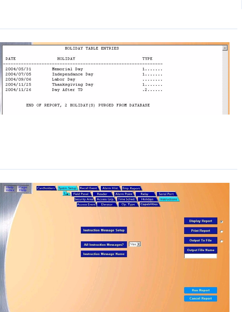
Chapter 7
Reports
125
Figure 95.Sample Holiday Setup report
Instruction Message Setup Report
The Instruction Message Setup Report recalls how Instruction Messages have been setup.
To navigate to the Instruction Message Setup Report page, from any page within the System
Setup pages click the Instruction Messages tab button in the top navigation bar. The following
page displays.
Figure 96.System Setup: Instructions
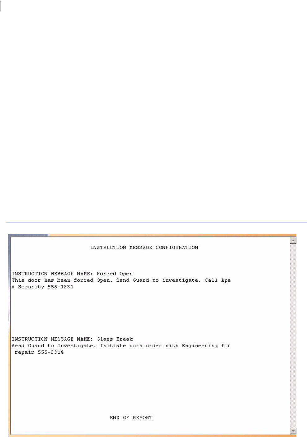
Topa z
User Manual
126
The Instructions page contains the following information:
Below is a sample of a displayed report for Instruction Message Setup.
Figure 97.Sample Instruction Message Setup report
Instruction Message
Setup
The Instruction Message Setup report recalls how instruction messages have been setup.
All Instruction
Messages?
If Yes is selected, all instruction messages are listed on the report. If No is selected, then an
instruction message must be selected from the drop-down list under Instruction Message Name.
Instruction Message
Name
From the drop-down list of pre-configured alarm points, scroll through and select the instruction
message to be recalled in the report by clicking on the Instruction Message Name.
Display Report This is the default. Click to display on the Workstation monitor.
Print Report Click to send to the report printer.
Output To File Click to save the report into the file name specified in the Output File Name field. This saves the
report results in a file for later use outside of Topaz.
Output File Name If you selected Output to File, enter the name of the file to contain the report information. The Output
File Name can have up to 64 characters. For example, you can type “Myreport” and the report is
saved into the file named Myreport in the directory where Topaz was installed. You may enter a path
with the file name, for example, “c:\reports\Myreport”. The format of the report files is always plain text
that can be opened in Notepad.
Run Report Click to send the report to the destination specified (display, printer, or file). A message “Report
Completed” displays, with the number of records printed. Click OK to continue.
Cancel Report Click to stop the report or when you have finished viewing the report on the monitor. This cancels the
operation and returns to the report screen. If no report displays and you click Cancel, it returns to the
Reports page.
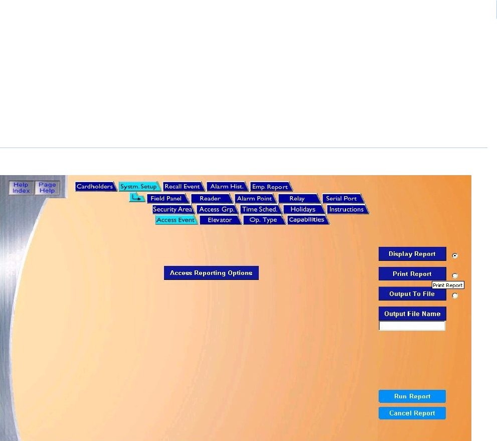
Chapter 7
Reports
127
Access Event Reporting Options Setup Report
The Access Event Reporting Options Setup Report recalls how Access Events have been setup.
To navigate to the Access Event Reporting Options Setup Report page, from any page within the
System Setup pages click the Access Reporting Options tab button in the top navigation bar. The
following page displays.
Figure 98.System Setup: Access Event
The Access Event page contains the following information:
Access Reporting
Options
The Access Reporting Options report recalls how access events have been set up. The report lists all
configured access reporting options.
Display Report This is the default. Click to display on the Workstation monitor.
Print Report Click to send to the report printer.
Output To File Click to save the report into the file name specified in the Output File Name field. This saves the
report results in a file for later use outside of Topaz.
Output File Name If you selected Output to File, enter the name of the file to contain the report information. The Output
File Name can have up to 64 characters. For example, you can type “Myreport” and the report is
saved into the file named Myreport in the directory where Topaz was installed. You may enter a path
with the file name, for example, “c:\reports\Myreport”. The format of the report files is always plain text
that can be opened in Notepad.
Run Report Click to send the report to the destination specified (display, printer, or file). A message “Report
Completed” displays, with the number of records printed. Click OK to continue.
Cancel Report Click to stop the report or when you have finished viewing the report on the monitor. This cancels the
operation and returns to the report screen. If no report displays and you click Cancel, it returns to the
Reports page.
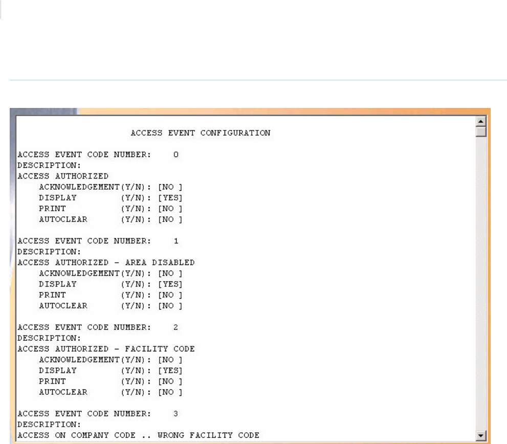
Topa z
User Manual
128
Below is a sample of a displayed report for Access Event Reporting Options setup.
Figure 99.Sample Access Event Reporting Options Setup report
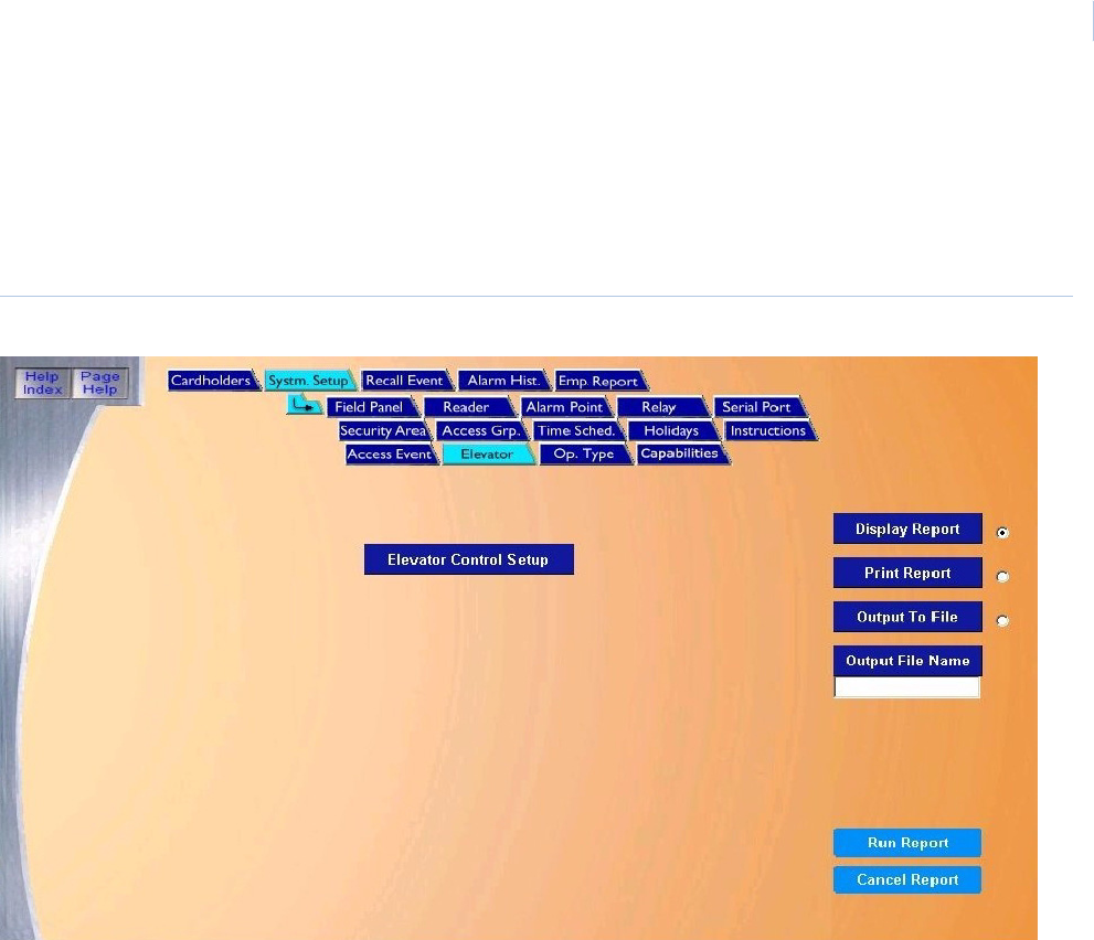
Chapter 7
Reports
129
Elevator Control Setup Report
The Elevator Control Setup Report recalls how elevators have been setup.
To navigate to the Elevator Control Setup Report page, from any page within the System Setup
pages click the Elevator tab button in the top navigation bar. The following page displays.
Figure 100.System Setup: Elevator
The Elevator page contains the following information:
Below is a sample of a displayed report for Elevator Control Setup.
Elevator Control
Setup
The Elevator Control Setup report recalls how elevators have been set up. The report lists all
configured elevators.
Display Report This is the default. Click to display on the Workstation monitor.
Print Report Click to send to the report printer.
Output To File Click to save the report into the file name specified in the Output File Name field. This saves the
report results in a file for later use outside of Topaz.
Output File Name If you selected Output to File, enter the name of the file to contain the report information. The Output
File Name can have up to 64 characters. For example, you can type “Myreport” and the report is
saved into the file named Myreport in the directory where Topaz was installed. You may enter a path
with the file name, for example, “c:\reports\Myreport”. The format of the report files is always plain text
that can be opened in Notepad.
Run Report Click to send the report to the destination specified (display, printer, or file). A message “Report
Completed” displays, with the number of records printed. Click OK to continue.
Cancel Report Click to stop the report or when you have finished viewing the report on the monitor. This cancels the
operation and return to the report screen. If no report displays and you click Cancel, it returns to the
Reports page.
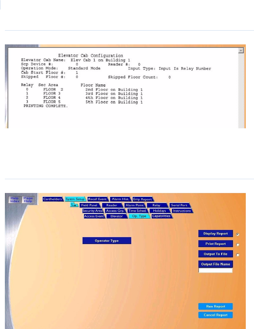
Topa z
User Manual
130
Figure 101.Sample Elevator Control Setup report
Operator Type Report
The Operator Type Report recalls the different Operator Types that have been defined.
To navigate to the Operator Type Report page, from any page within the System Setup pages click
the Op. Type tab button in the top navigation bar. The following page displays.
Figure 102.System Setup: Operator Type
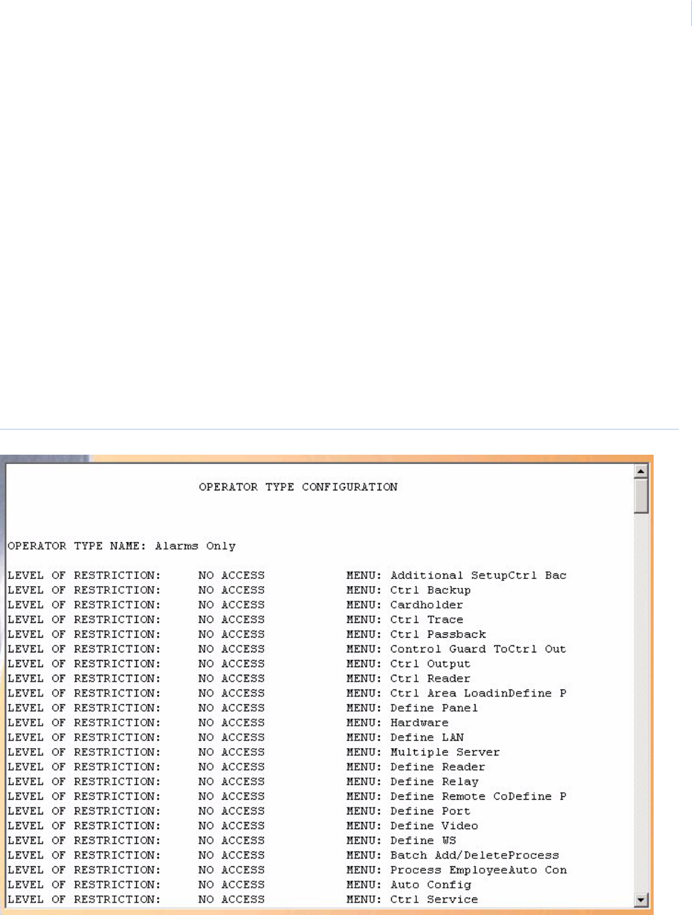
Chapter 7
Reports
131
The Operator Type page contains the following information:
Below is a sample of a displayed report for Operator Type.
Figure 103.Sample Operator Type report
Operator Type The Operator Type report recalls how operator types have been set up. The report lists all configured
operator types.
Display Report This is the default. Click to display on the Workstation monitor.
Print Report Click to send to the report printer.
Output To File Click to save the report into the file name specified in the Output File Name field. This saves the
report results in a file for later use outside of Topaz.
Output File Name If you selected Output to File, enter the name of the file to contain the report information. The Output
File Name can have up to 64 characters. For example, you can type “Myreport” and the report is
saved into the file named Myreport in the directory where Topaz was installed. You may enter a path
with the file name, for example, “c:\reports\Myreport”. The format of the report files is always plain text
that can be opened in Notepad.
Run Report Click to send the report to the destination specified (display, printer, or file). A message “Report
Completed” displays, with the number of records printed. Click OK to continue.
Cancel Report Click to stop the report or when you have finished viewing the report on the monitor. This cancels the
operation and returns to the report screen. If no report displays and you click Cancel, it returns to the
Reports page.
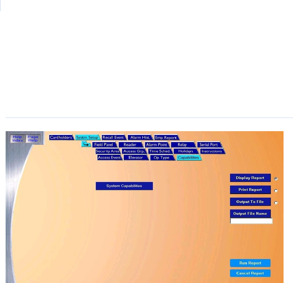
Topa z
User Manual
132
Capabilities Report
The Setup Capabilities Report provides detailed information as to the maximum capabilities that
are configured on your system. For example, how many card readers you can address, the number
of cardholders you may add, optional programs supported by your system. At the bottom, the report
will show how much space is left in your Topaz archive file.
To navigate to the Setup Capabilities Report page, click the Report button in the main navigation
bar at the left side of the browser window, then click the button next to System Setup on the main
Reports page then click the Capabilities tab button at the top of the window. You can also click the
System Setup – Capabilities tab at the top of the window from any reports page.
Figure 104.System Setup: Capabilities
The Capabilities page contains the following information:
System Capabilities The System Capabilities report recalls the maximum capabilities configured on your system.
Display Report This is the default. Click to display on the Workstation monitor.
Print Report Click to send to the report printer.
Output To File Click to save the report into the file name specified in the Output File Name field. This saves the
report results in a file for later use outside of Topaz.
Output File Name If you selected Output to File, enter the name of the file to contain the report information. The Output
File Name can have up to 64 characters. For example, you can type “Myreport” and the report is
saved into the file named Myreport in the directory where Topaz was installed. You may enter a path
with the file name, for example, “c:\reports\Myreport”. The format of the report files is always plain
text that can be opened in Notepad.
Run Report Click to send the report to the destination specified (display, printer, or file). A message “Report
Completed” displays, with the number of records printed. Click OK to continue.
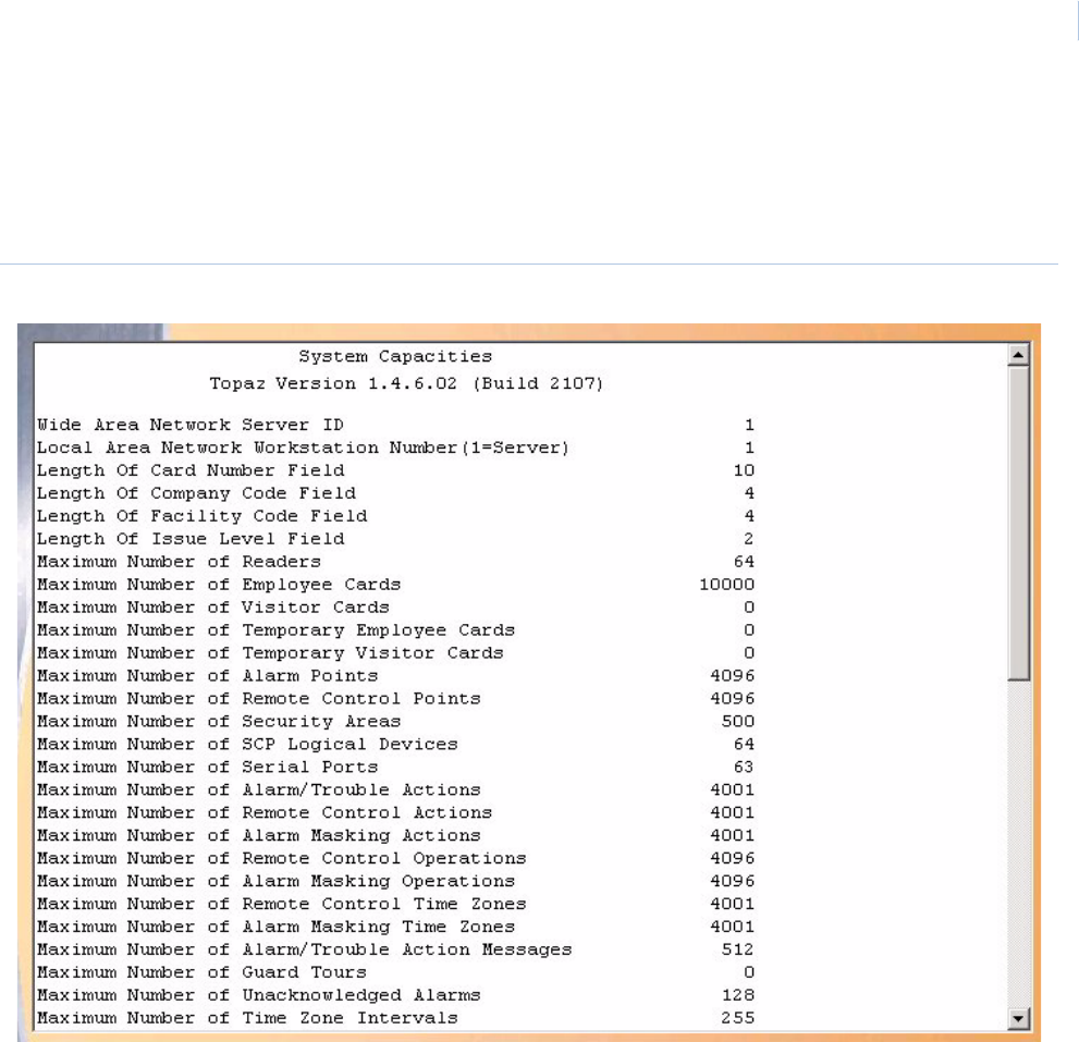
Chapter 7
Reports
133
Below is a sample of part of a displayed report for System Capacities.
Figure 105.Sample System Capacities report
Cancel Report Click to stop the report or when you have finished viewing the report on the monitor. This cancels the
operation and return to the report screen. If no report displays and you click Cancel, it returns to the
Reports page.
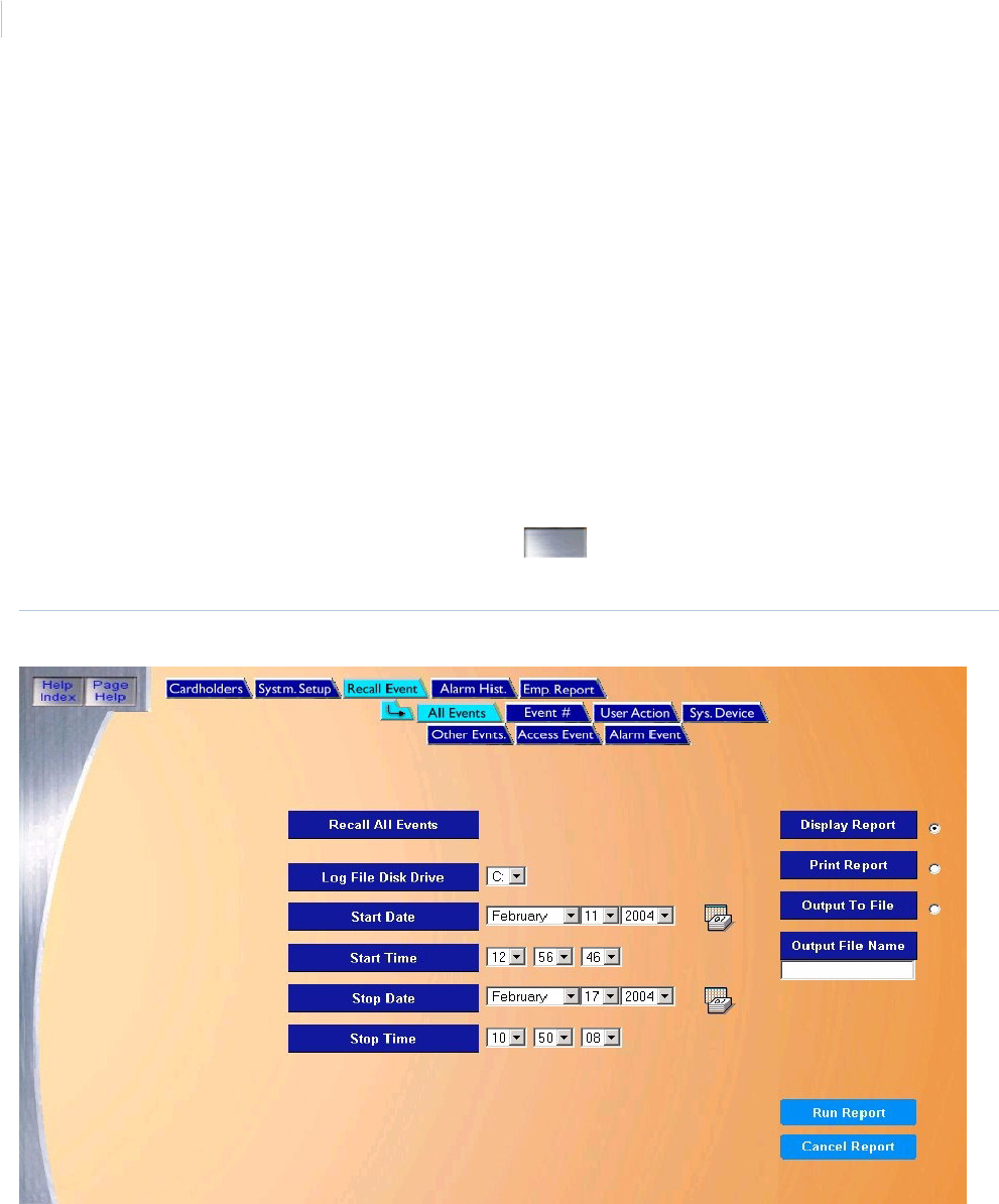
Topa z
User Manual
134
Recall Event Reports Page
These reports can display and print out a complete listing of all events recorded to the current on-line
event log file, events that occurred while the server was shut down, or events that have been
archived or backed up. The fields on the Recall All Events screen can be modified to reduce or
expand the report range.
The Recall Event page allows you to retrieve historical information by the following types of events
Recall All Events Report on page 135
Recall By Event Number Report on page 137
Recall User Actions Report on page 139
Recall System Device Events Report on
page 141
Recall Other Events Report on page 143
Recall Access Events Report on page 146
Recall Alarm Events Report on page 149
To select the Recall Events page, from the Main browser toolbar on the left side of the browser
window click the Reports button, and then click the button corresponding to Recall Event, or
from any Reports page, click the Recall Event tab button. The following page displays.
Figure 106.Recall Event
These reports are covered in detail in the pages that follow.

Chapter 7
Reports
135
Recall All Events Report
This procedure recalls all logged events by time period.
To navigate to the report, from any page within the Reports pages click the Recall Event tab button.
The following All Events page displays.
Figure 107.Recall Event: All Events
The Recall All Events page contains the following information:
Recall All Events This report recalls all logged events by time period.
Log File Disk Drive Select the drive letter where the history log file is located. The default is the C: drive of your computer.
If the report is being recalled from a removable drive, make sure the removable disk has been
inserted.
Start Date From the drop-down list select the Month, Day, and Year on which the report should start. A full
calendar can be displayed by clicking the Calendar icon.
Note: If you wish to recall all events in the history log file, skip the Start and End Date and Time.
They default to the first and last event in the log file.
Start Time From the drop-down list select the Hour, Minute, and Seconds on which the report should start.
Stop Date From the drop-down list select the Month, Day, and Year on which the report should stop. A full
calendar can be displayed by clicking the Calendar icon.
Stop Time From the drop-down list select the Hour, Minute, and Seconds on which the report should stop.
Display Report This is the default. Click to display on the Workstation monitor.
Print Report Click to send to the report printer.
Output To File Click to save the report into the file name specified in the Output File Name field. This saves the
report results in a file for later use outside of Topaz.
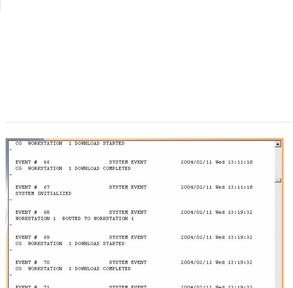
Topa z
User Manual
136
Below is a sample of part of a displayed report for Recall All Events:
Figure 108.Sample Recall All Events report
Output File Name If you selected Output to File, enter the name of the file to contain the report information. The Output
File Name can have up to 64 characters. For example, you can type “Myreport” and the report is
saved into the file named Myreport in the directory where Topaz was installed. You may enter a path
with the file name, for example, “c:\reports\Myreport”. The format of the report files is always plain text
that can be opened in Notepad.
Run Report Click to send the report to the destination specified (display, printer, or file). A message “Report
Completed” displays, with the number of records printed. Click OK to continue.
Cancel Report Click to stop the report or when you have finished viewing the report on the monitor. This cancels the
operation and returns to the report screen. If no report displays and you click Cancel, it returns to the
Reports page.
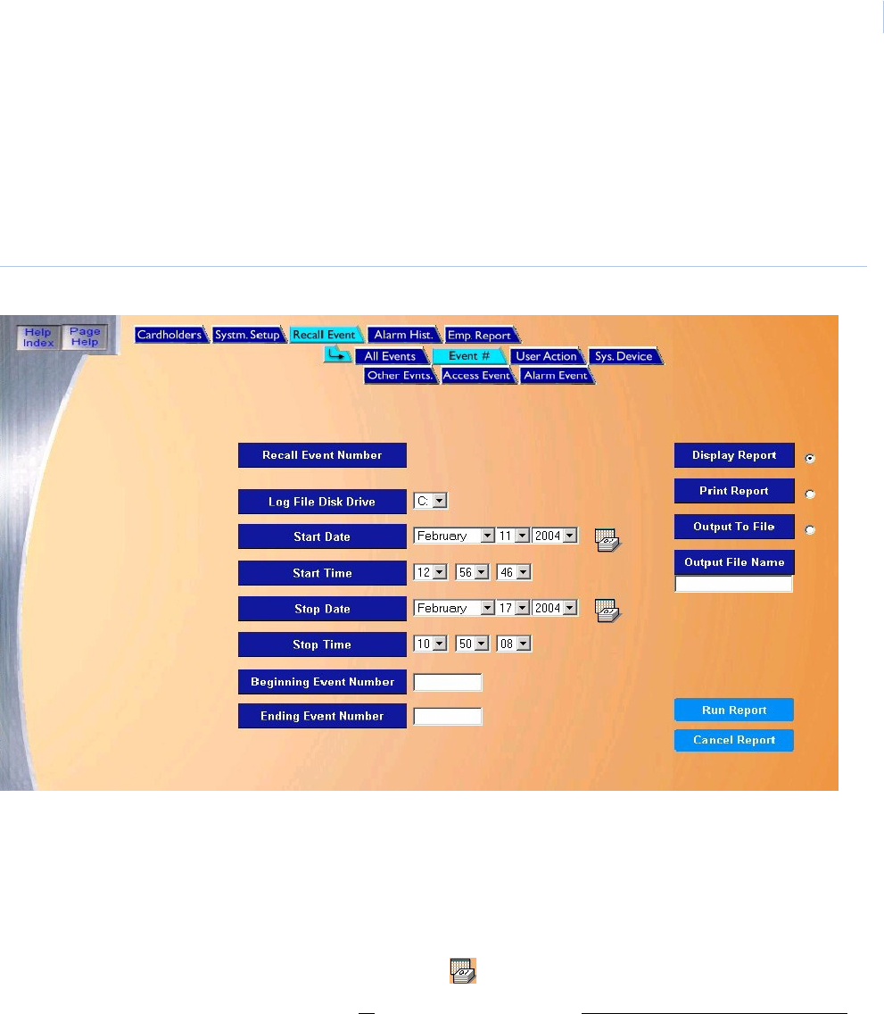
Chapter 7
Reports
137
Recall By Event Number Report
To navigate to the Recall by Event Number reports page, from the Main Reports page click the
Recall Events tab button at the top and/or then click the Event # tab button in the Recall Events
pages. The following page displays.
Note: Recalling events by number is an extremely slow process. Where possible, recall events by time.
Figure 109.Recall Event: Event Number
The Recall Event # page contains the following information:
Recall Event Number This report recalls events by event number.
Log File Disk Drive Select the drive letter where the history log file is located. The default is the C: drive of your computer.
If the report is being recalled from a removable drive, make sure the removable disk has been
inserted.
Start Date From the drop-down list select the Month, Day, and Year on which the report should start. A full
calendar can be displayed by clicking the Calendar icon.
Note: If you wish to recall all events in the history log file, skip the Start and End Date and Time.
They default to the first and last event in the log file.
Start Time From the drop-down list select the Hour, Minute, and Seconds on which the report should start.
Stop Date From the drop-down list select the Month, Day, and Year on which the report should stop. A full
calendar can be displayed by clicking the Calendar icon.
Stop Time From the drop-down list select the Hour, Minute, and Seconds on which the report should stop.
Beginning Event
Number
Enter the event number desired for the first event of the report. The default number is the first event in
the history log file.
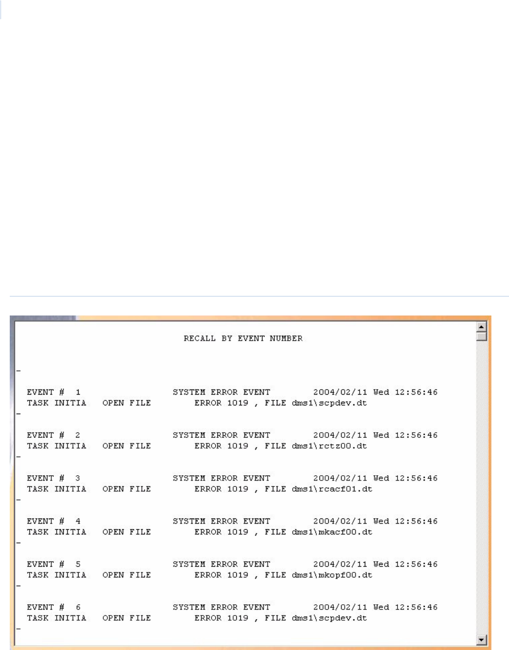
Topa z
User Manual
138
Below is a sample of part of a displayed report for Recall by Event Number:
Figure 110.Sample Recall by Event Number report
Ending Event
Number
Enter the event number for the last event of the report. The default number is the last event in the
history log file.
Display Report This is the default. Click to display on the Workstation monitor.
Print Report Click to send to the report printer.
Output To File Click to save the report into the file name specified in the Output File Name field. This saves the
report results in a file for later use outside of Topaz.
Output File Name If you selected Output to File, enter the name of the file to contain the report information. The Output
File Name can have up to 64 characters. For example, you can type “Myreport” and the report is
saved into the file named Myreport in the directory where Topaz was installed. You may enter a path
with the file name, for example, “c:\reports\Myreport”. The format of the report files is always plain text
that can be opened in Notepad.
Run Report Click to send the report to the destination specified (display, printer, or file). A message “Report
Completed” displays, with the number of records printed. Click OK to continue.
Cancel Report Click to stop the report or when you have finished viewing the report on the monitor. This cancels the
operation and return to the report screen. If no report displays and you click Cancel, it returns to the
Reports page.
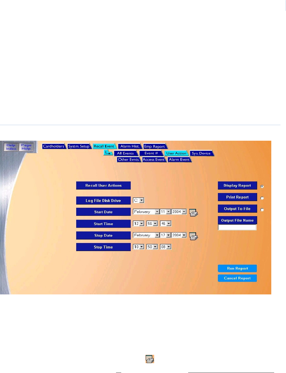
Chapter 7
Reports
139
Recall User Actions Report
The Recall User Actions Report recalls a description of the action performed by the system
operators during a selected period of time. If an operator has performed an operation other than
displaying or printing information, the description includes a more detailed explanation of the
operation, such as creating a monitor point or deleting a disk file.
Note: The program cannot verify the person that used a password was indeed the operator assigned to that password,
only that the operator who performed the action was using that password. Consequently, you should advise all
system operators NOT to reveal their passwords to anyone else, including other system operators.
To navigate to the report, from the Main Reports page click the Recall Events tab button at the top
and then click the User Action tab button. The following page displays.
Figure 111.Recall Event: User Action
The User Action page contains the following information:
Recall User Actions This report recalls a description of the action performed by the system operators during a selected
period of time.
Log File Disk Drive Select the drive letter where the history log file is located. The default is the C: drive of your computer.
If the report is being recalled from a removable drive, make sure the removable disk has been
inserted.
Start Date From the drop-down list select the Month, Day, and Year on which the report should start. A full
calendar can be displayed by clicking the Calendar icon.
Note: If you wish to recall all events in the history log file, skip the Start and End Date and Time.
They default to the first and last event in the log file.
Start Time From the drop-down list select the Hour, Minute, and Seconds on which the report should start.
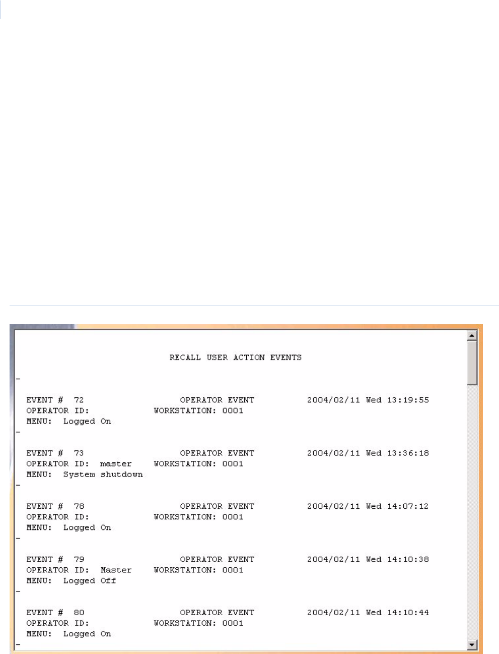
Topa z
User Manual
140
Below is a sample of a displayed Recall User Actions report.
Figure 112.Sample Recall User Action Events report
Stop Date From the drop-down list select the Month, Day, and Year on which the report should stop. A full
calendar can be displayed by clicking the Calendar icon.
Stop Time From the drop-down list select the Hour, Minute, and Seconds on which the report should stop.
Display Report This is the default. Click to display on the Workstation monitor.
Print Report Click to send to the report printer.
Output To File Click to save the report into the file name specified in the Output File Name field. This saves the report
results in a file for later use outside of Topaz.
Output File Name If you selected Output to File, enter the name of the file to contain the report information. The Output
File Name can have up to 64 characters. For example, you can type “Myreport” and the report is
saved into the file named Myreport in the directory where Topaz was installed. You may enter a path
with the file name, for example, “c:\reports\Myreport”. The format of the report files is always plain text
that can be opened in Notepad.
Run Report Click to send the report to the destination specified (display, printer, or file). A message “Report
Completed” displays, with the number of records printed. Click OK to continue.
Cancel Report Click to stop the report or when you have finished viewing the report on the monitor. This cancels the
operation and returns to the report screen. If no report displays and you click Cancel, it returns to the
Reports page.
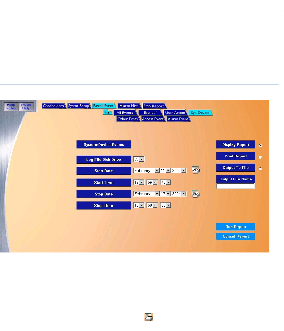
Chapter 7
Reports
141
Recall System Device Events Report
The Recall System Device Events Report recalls all system and device events that occurred
during your selected period of time.
To navigate to the report, from the Main Reports page click the Recall Events tab button in the top
navigation toolbar and then click the Sys. Device tab button. The following page displays.
Figure 113.Recall Event: System Device
The System Device page contains the following information:
System/Device
Events
This report recalls all system and device events that occurred during your selected period of time.
Log File Disk Drive Select the drive letter where the history log file is located. The default is the C: drive of your computer.
If the report is being recalled from a removable drive, make sure the removable disk has been
inserted.
Start Date From the drop-down list select the Month, Day, and Year on which the report should start. A full
calendar can be displayed by clicking the Calendar icon.
Note: If you wish to recall all events in the history log file, skip the Start and End Date and Time.
They default to the first and last event in the log file.
Start Time From the drop-down list select the Hour, Minute, and Seconds on which the report should start.
Stop Date From the drop-down list select the Month, Day, and Year on which the report should stop. A full
calendar can be displayed by clicking the Calendar icon.
Stop Time From the drop-down list select the Hour, Minute, and Seconds on which the report should stop.
Display Report This is the default. Click to display on the Workstation monitor.
Print Report Click to send to the report printer.
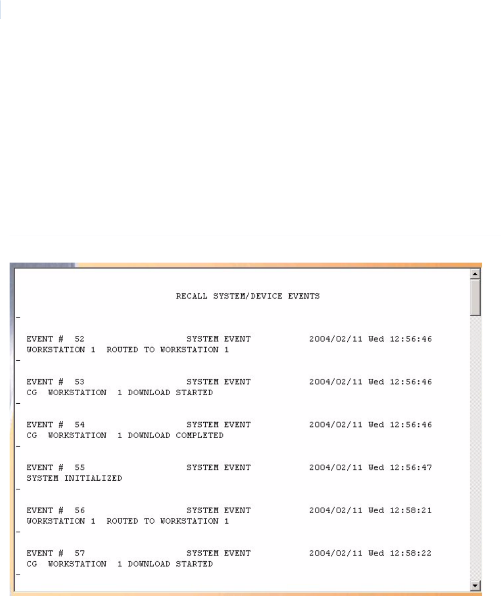
Topa z
User Manual
142
Below is a sample of a displayed Recall System Device Events report.
Figure 114.Sample Recall System/Device Events report
Output To File Click to save the report into the file name specified in the Output File Name field. This saves the
report results in a file for later use outside of Topaz.
Output File Name If you selected Output to File, enter the name of the file to contain the report information. The Output
File Name can have up to 64 characters. For example, you can type “Myreport” and the report is
saved into the file named Myreport in the directory where Topaz was installed. You may enter a path
with the file name, for example, “c:\reports\Myreport”. The format of the report files is always plain text
that can be opened in Notepad.
Run Report Click to send the report to the destination specified (display, printer, or file). A message “Report
Completed” displays, with the number of records printed. Click OK to continue.
Cancel Report Click to stop the report or when you have finished viewing the report on the monitor. This cancels the
operation and returns to the report screen. If no report displays and you click Cancel, it returns to the
Reports page.
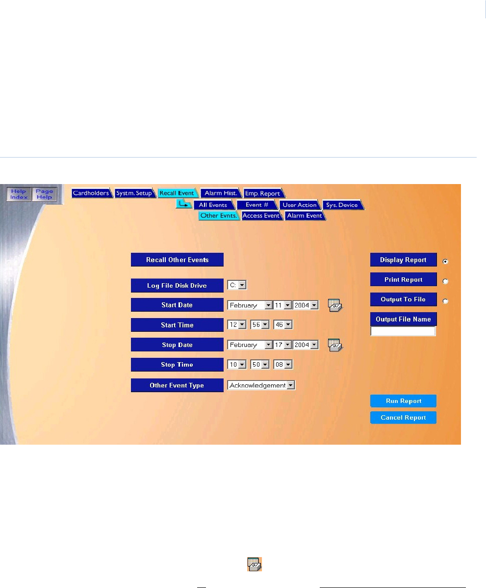
Chapter 7
Reports
143
Recall Other Events Report
The Recall Other Events Report recalls all events not covered in any of the other reports like,
Acknowledgement, Commentary, Remote Control, Alarm Masking, Keypad Time Zone, Secure Area
Monitor, Redundant System, Ack Timeout, System Error, etc.
To navigate to the report, from within any Reports page click the Recall Events tab button in the top
navigation bar and then click the Other Events tab button. The following page displays.
Figure 115.Recall Event: Other Events
The Other Events page contains the following information:
Recall Other Events This report recalls all events not covered in any of the other reports like, Acknowledgement,
Commentary, Remote Control, Alarm Masking, Keypad Time Zone, Secure Area Monitor, Redundant
System, Ack Timeout, System Error, etc.
Log File Disk Drive Select the drive letter where the history log file is located. The default is the C: drive of your computer.
If the report is being recalled from a removable drive, make sure the removable disk has been
inserted.
Start Date From the drop-down list select the Month, Day, and Year on which the report should start. A full
calendar can be displayed by clicking the Calendar icon.
Note: If you wish to recall all events in the history log file, skip the Start and End Date and Time.
They default to the first and last event in the log file.
Start Time From the drop-down list select the Hour, Minute, and Seconds on which the report should start.
Stop Date From the drop-down list select the Month, Day, and Year on which the report should stop. A full
calendar can be displayed by clicking the Calendar icon.
Stop Time From the drop-down list select the Hour, Minute, and Seconds on which the report should stop.
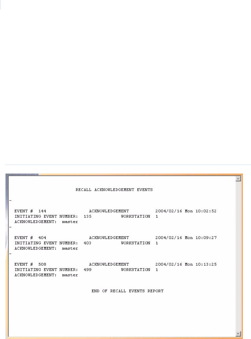
Topa z
User Manual
144
Below is a sample of a displayed Acknowledged events report.
Figure 116.Sample Recall Acknowledgement Events report
Other Event Type • Acknowledge - Recalls the workstation the event number was acknowledged from, password
used, time and date acknowledged.
• Commentary - Recalls the workstation the event was acknowledged from, commentary entered
by the operator, time and date the commentary was entered.
• System Error - Recalls system errors that occurred, time and date of occurrence.
Display Report This is the default. Click to display on the Workstation monitor.
Print Report Click to send to the report printer.
Output To File Click to save the report into the file name specified in the Output File Name field. This saves the report
results in a file for later use outside of Topaz.
Output File Name If you selected Output to File, enter the name of the file to contain the report information. The Output
File Name can have up to 64 characters. For example, you can type “Myreport” and the report is
saved into the file named Myreport in the directory where Topaz was installed. You may enter a path
with the file name, for example, “c:\reports\Myreport”. The format of the report files is always plain text
that can be opened in Notepad.
Run Report Click to send the report to the destination specified (display, printer, or file). A message “Report
Completed” displays, with the number of records printed. Click OK to continue.
Cancel Report Click to stop the report or when you have finished viewing the report on the monitor. This cancels the
operation and return to the report screen. If no report displays and you click Cancel, it returns to the
Reports page.
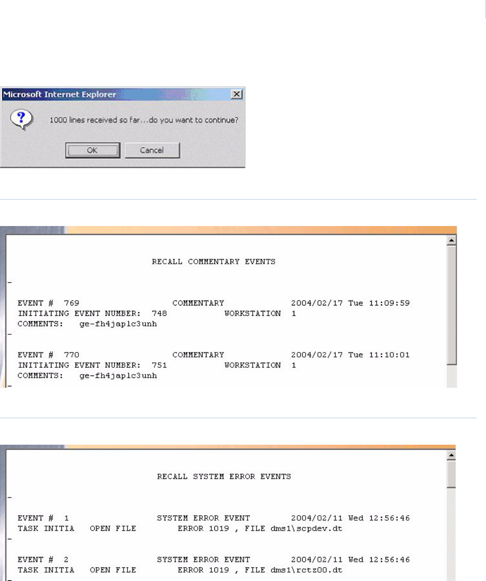
Chapter 7
Reports
145
If the report recalls more than 1000 events, the message below is displayed allowing you the
opportunity to cancel the search for additional events.
Below is a sample of a displayed Commentary events report.
Figure 117.Sample Recall Commentary Events report
Below is a sample of a displayed System Error events report.
Figure 118.Sample Recall System Error Events report
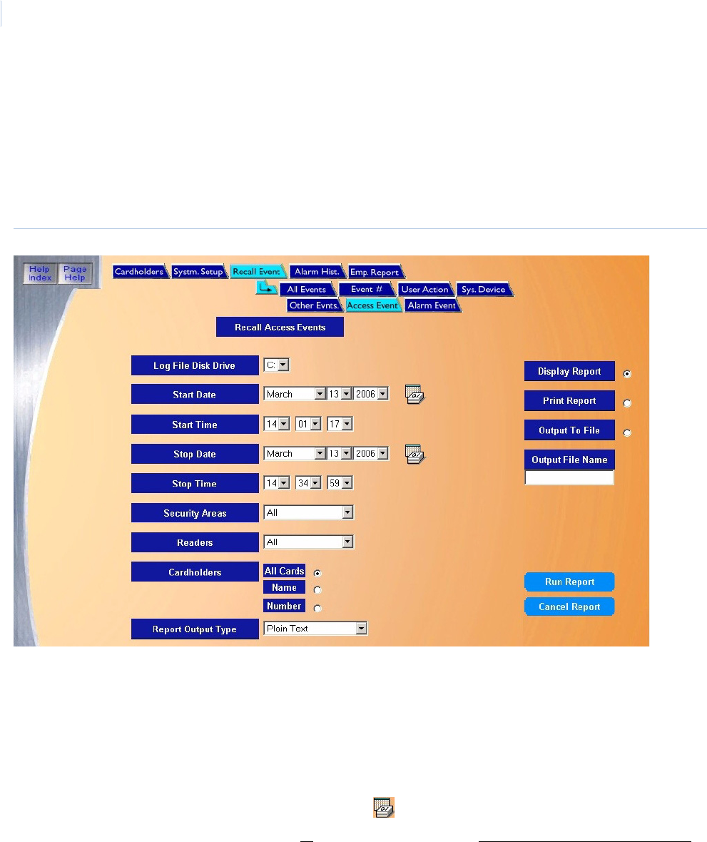
Topa z
User Manual
146
Recall Access Events Report
The Recall Access Events Report recalls all access events for a selected time period and all
security areas and all readers or a specific security area or reader.
To navigate to the Recall Access Events Report page from within the report pages click the Recall
Events tab button in the top navigation bar and then click the Access Events tab button. The
following page displays.
Figure 119.Recall Event: Access Event
The Access Event page contains the following information:
Recall Access EventsThis report recalls access events for a selected time period and all security areas and all readers or a
specific security area or reader.
Log File Disk Drive Select the drive letter where the history log file is located. The default is the C: drive of your computer.
If the report is being recalled from a removable drive, make sure the removable disk has been
inserted.
Start Date From the drop-down list select the Month, Day, and Year on which the report should start. A full
calendar can be displayed by clicking the Calendar icon.
Note: If you wish to recall all events in the history log file, skip the Start and End Date and Time.
They default to the first and last event in the log file.
Start Time From the drop-down list select the Hour, Minute, and Seconds on which the report should start.
Stop Date From the drop-down list select the Month, Day, and Year on which the report should stop. A full
calendar can be displayed by clicking the Calendar icon.
Stop Time From the drop-down list select the Hour, Minute, and Seconds on which the report should stop.
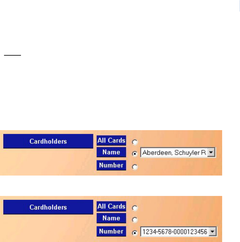
Chapter 7
Reports
147
Security Areas From the drop-down list of pre-configured areas select the Security Area for which all Access Events
are to be recalled. The default is all security areas. If a single security area is selected, the readers
option will not be available. Only one or all security areas can be recalled in a single report. If more
than one security area is desired, additional reports must be run for each area.
Readers Select the Reader for which Access Events are to be recalled. The default is all readers. If a single
reader is selected, the security areas option will not be available. Only one or all readers can be
recalled in a single report. If more than one reader is desired, additional reports must be run for each
reader.
Cardholders • All Cards – When selected, this option recalls all access events for all cards for the selected
area(s)/reader(s).
• Name – When selected, this option allows you to select one cardholders name from a drop-down
list to recall access events for.
• Number - When selected, this option allows you to select one card number from a drop-down list
to recall access events for.
Report Output Type Select the type of report that you want to view:
• Plain Text: Displays the report in the normal text format.
• Linked Video (HTML): Displays the report in a separate window, formatted as a table with Video
references that you can click to view the video clip associated with the access event.
Note: To view the video clip, you must be able to connect to the DVMR and the clip must
still be in the DVMR disk.
Display Report This is the default. Click to display on the Workstation monitor.
Print Report Click to send to the report printer.
Output To File Click to save the report into the file name specified in the Output File Name field. This saves the
report results in a file for later use outside of Topaz.
Output File Name If you selected Output to File, enter the name of the file to contain the report information. The Output
File Name can have up to 64 characters. For example, you can type “Myreport” and the report is
saved into the file named Myreport in the directory where Topaz was installed. You may enter a path
with the file name, for example, “c:\reports\Myreport”. The format of the report files is always plain text
that can be opened in Notepad.
Run Report Click to send the report to the destination specified (display, printer, or file). A message “Report
Completed” displays, with the number of records printed. Click OK to continue.
Cancel Report Click to stop the report or when you have finished viewing the report on the monitor. This cancels the
operation and returns to the report screen. If no report displays and you click Cancel, it returns to the
Reports page.
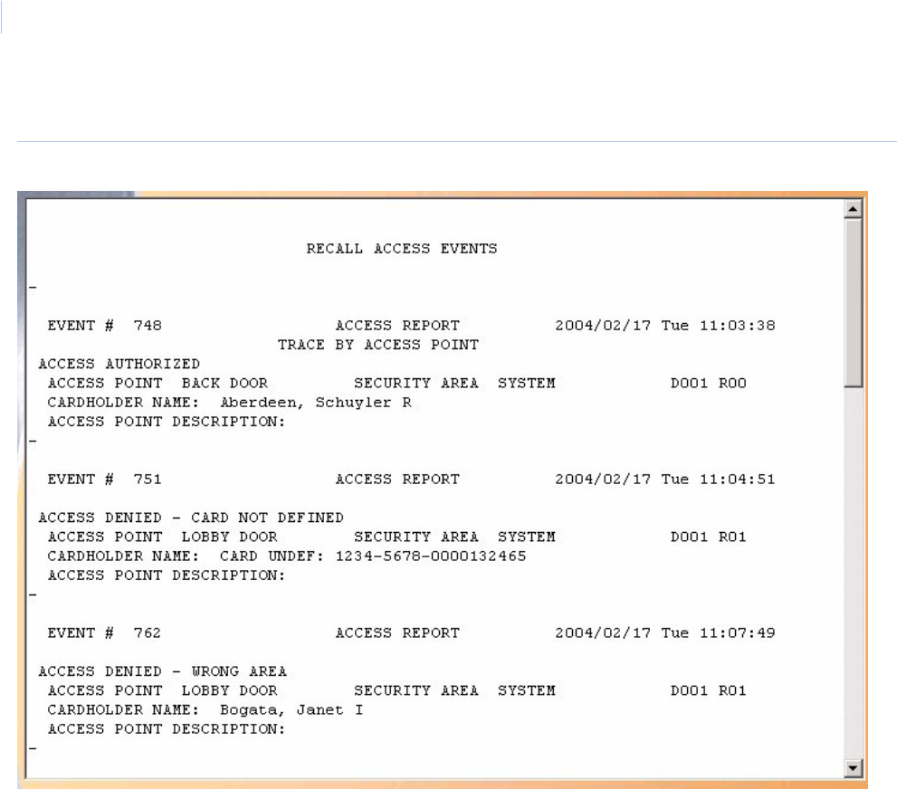
Topa z
User Manual
148
Below is a sample of a displayed Recall Access Events report.
Figure 120.Sample Recall Access Events report
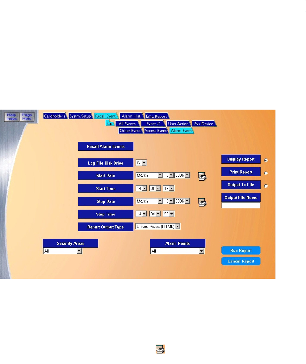
Chapter 7
Reports
149
Recall Alarm Events Report
The Recall Alarm Events Report recalls all alarm events for a selected time period for all security
areas and all alarm points or a specific security area or alarm point.
To navigate to the Recall Alarm Events Report from within Report pages click the Recall Events
tab button in the top navigation bar and then click the Alarm Event tab button. The following page
displays.
Figure 121.Recall Event: Alarm Event
The Alarm Event page contains the following information:
Recall Alarm Events This report recalls all alarm events for a selected time period for all security areas and all alarm points
or a specific security area or alarm point.
Log File Disk Drive Select the drive letter where the history log file is located. The default is the C: drive of your computer.
If the report is being recalled from a removable drive, make sure the removable disk has been
inserted.
Start Date From the drop-down list select the Month, Day, and Year on which the report should start. A full
calendar can be displayed by clicking the Calendar icon.
Note: If you wish to recall all events in the history log file, skip the Start and End Date and Time.
They default to the first and last event in the log file.
Start Time From the drop-down list select the Hour, Minute, and Seconds on which the report should start.
Stop Date From the drop-down list select the Month, Day, and Year on which the report should stop. A full
calendar can be displayed by clicking the Calendar icon.
Stop Time From the drop-down list select the Hour, Minute, and Seconds on which the report should stop.

Topa z
User Manual
150
Security Areas Select the Security Area for All Alarm Events are to be recalled. The default is all security areas. If a
single security area is selected, the alarm points option will not be selectable. Only one or all security
areas can be recalled in a single report. If more than one security area is desired, additional reports
must be run for each security area desired.
Alarm Points Select the Alarm Point for which alarm events are to be recalled. The default is all alarm points. If a
single alarm point is selected the security areas option will not be available. Only one or all alarm
points can be recalled in a single report. If more than one alarm point is desired, additional reports
must be run for each alarm point.
Report Output Type Select the type of report that you want to view:
• Plain Text: Displays the report in the normal text format.
• Linked Video (HTML): Displays the report in a separate window, formatted as a table with Video
references that you can click to view the video clip associated with the alarm event.
Note: To view the video clip, you must be able to connect to the DVMR and the clip must still be in
the DVMR disk.
Display Report This is the default. Click to display on the Workstation monitor.
Print Report Click to send to the report printer.
Output To File Click to save the report into the file name specified in the Output File Name field. This saves the
report results in a file for later use outside of Topaz.
Output File Name If you selected Output to File, enter the name of the file to contain the report information. The Output
File Name can have up to 64 characters. For example, you can type “Myreport” and the report is
saved into the file named Myreport in the directory where Topaz was installed. You may enter a path
with the file name, for example, “c:\reports\Myreport”. The format of the report files is always plain text
that can be opened in Notepad.
Run Report Click to send the report to the destination specified (display, printer, or file). A message “Report
Completed” displays, with the number of records printed. Click OK to continue.
Cancel Report Click to stop the report or when you have finished viewing the report on the monitor. This cancels the
operation and returns to the report screen. If no report displays and you click Cancel, it returns to the
Reports page.
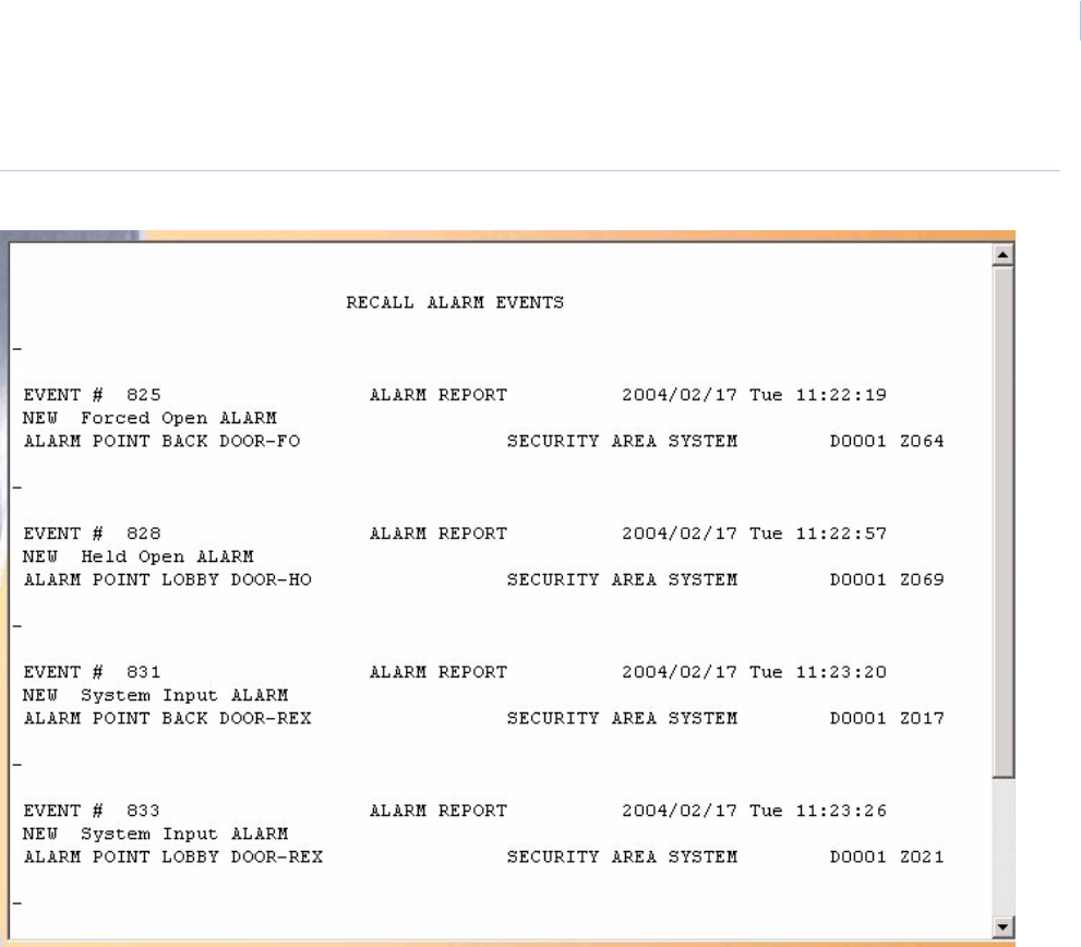
Chapter 7
Reports
151
Below is a sample of a displayed report for Recall Alarm Events.
Figure 122.Sample Recall Alarm Events report
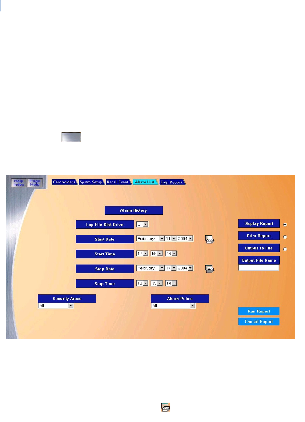
Topa z
User Manual
152
Alarm History Reports Page
The Alarm History Report recalls summarized history reports of alarms and troubles that have
occurred during a specified period of time by alarm point or security area. The report calculates the
following for any alarm in the report:
•Frequency - The number of times the alarm occurred in the time period selected.
•Total Duration - The length of time the alarm point was in alarm for each occurrence and
then the sum total of all those occurrences.
•Longest Duration - The longest time for any single occurrence when the point was in an
alarm condition.
To navigate to Alarm History Reports click the Reports button located in the left browser window or
the corresponding button. Then click the Alarm Hist. tab button at the top of the browser. The
following page displays.
Figure 123.Alarm History
The Alarm History page contains the following information:
Alarm History This report recalls summarized history reports of alarms and troubles that have occurred during a
specified period of time by alarm point or security area.
Log File Disk Drive Select the drive letter where the history log file is located. The default is the C: drive of your computer.
If the report is being recalled from a removable drive, make sure the removable disk has been
inserted.
Start Date From the drop-down list select the Month, Day, and Year on which the report should start. A full
calendar can be displayed by clicking the Calendar icon.
Note: If you wish to recall all events in the history log file, skip the Start and End Date and Time.
They default to the first and last event in the log file.
Start Time From the drop-down list select the Hour, Minute, and Seconds on which the report should start.

Chapter 7
Reports
153
Stop Date From the drop-down list select the Month, Day, and Year on which the report should stop. A full
calendar can be displayed by clicking the Calendar icon.
Stop Time From the drop-down list select the Hour, Minute, and Seconds on which the report should stop.
Security Areas Select the Security Area for which Alarm History is to be recalled. The default is all security areas with
all alarm points. If a single security area is selected the alarm points option will not be selectable.
Only one or all security areas can be recalled in a single report. If more than one security area is
desired, additional reports must be run for each security area desired.
Alarm Points Select the Alarm Point for which alarm history is to be recalled. The default is all alarm points. If a
single alarm point is selected the security areas option will not be available. Only one or all alarm
points can be recalled in a single report. If more than one alarm point is desired additional reports
must be run for each alarm point.
Display Report This is the default. Click to display on the Workstation monitor.
Print Report Click to send to the report printer.
Output To File Click to save the report into the file name specified in the Output File Name field. This saves the
report results in a file for later use outside of Topaz.
Output File Name If you selected Output to File, enter the name of the file to contain the report information. The Output
File Name can have up to 64 characters. For example, you can type “Myreport” and the report is
saved into the file named Myreport in the directory where Topaz was installed. You may enter a path
with the file name, for example, “c:\reports\Myreport”. The format of the report files is always plain text
that can be opened in Notepad.
Run Report Click to send the report to the destination specified (display, printer, or file). A message “Report
Completed” displays, with the number of records printed. Click OK to continue.
Cancel Report Click to stop the report or when you have finished viewing the report on the monitor. This cancels the
operation and returns to the report screen. If no report displays and you click Cancel, it returns to the
Reports page.
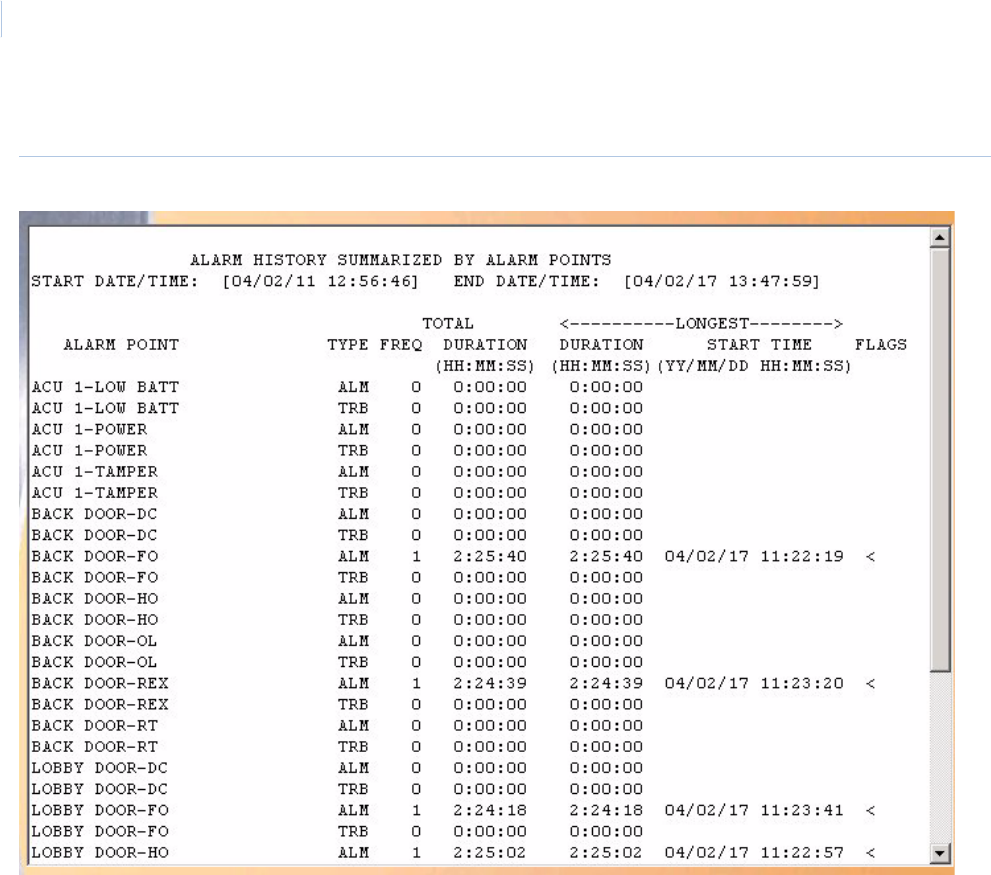
Topa z
User Manual
154
Below is a sample of a displayed Alarm History Report.
Figure 124.Sample Alarm History report

Chapter 7
Reports
155
Fields in the Report
The table below describes all fields (report columns and line entries) that can be included in an Alarm
History report. Whether or not the field is included is a function of the type of report and the report
options specified.
Table 7. Alarm History report fields
Report Item Description
Start Date/Time Beginning date/time for the reporting period you are requesting.
End Date/Time Ending date/time of reporting period.
TYPE Depending on the level of the report, this report column identifies a report line entry as either
CAT (Category) or TRB (Trouble):
C no. (category number) or T
no. (trouble number)
There can be multiple category or trouble number report lines
per reporting item, but report lines are generated only if there is
data to report for the report line entry.
ALM (Alarm) or TRB (Trouble) These two entries are always paired and there is always one
pair of report line entries per reporting item. One of the pair of
lines has time reported under “Duration” and the other has time
reported as all zeroes. The line with time reported as non-zero
indicates whether the alarm point had an Alarm or Trouble
event.
FREQ Reports the number of times the alarm or trouble occurred during the reporting period.
TOTAL DURATION Reports the total accumulated time that the alarm point(s) were active, or trouble(s) were
reported during the reporting period.
LONGEST DETAIL The following information is included in all reports for the alarm or trouble with the longest
duration
DURATION How long the longest alarm or trouble lasted.
START TIME The time at which the alarm or trouble originated. Additional identifying
information (for example, monitor point and category or trouble number
appears in system reports as appropriate).
FLAGS Flags are used to identify report line entries that are not contained within
the reporting period as follows:
Flag Meaning
> A reported event started earlier than the reporting period.
< A reported event ended after the reporting period.
* A negative time. The system clock has been reset while a
reported event occurred so that it appears to end before it
begins. (This can happen as a result of a reboot following a
system crash or as a result of resetting a clock for changes
between daylight savings and standard time.)
Since more than one alarm or trouble is reported per report line, more
than one type of flag can occur per report line. However, each type of
flag occurs only once per report line.
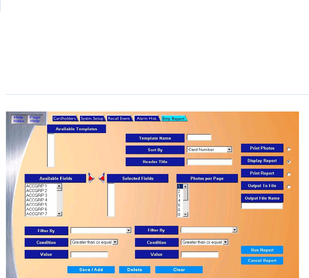
Topa z
User Manual
156
Employee Reports Page
The Employee Report can provide a wide range of information regarding any employee in the
system. You can set up different options depending upon what type of report is needed.
To navigate to the Employee Report page, from any page within the Reports pages click the
Employee Reports tab button at the top of the window. The following page displays.
Figure 125.Employee Report
The Employee Reports page contains the following information:
Available Templates You can select an already configured report from the list. To create a new report, type a new name in
the Template Name field.
Template Name Enter a Template Name of your choice to save the report template under. A template can be used in
the future without having to redesign all fields on the report. The name can be up to eight (8)
characters, not including punctuation.
Sort By Select how the report is to sort the data. There are four options listed below to sort the report by. Only
one of the four options can be selected for the current report.
• Card Number - Employees are reported in order of Card Numbers.
• Employee Name - Employees are reported in order of Employee Name.
• Employee Number - Employees are reported in order of Employee Number.
• Card Serial Number - Cardholder are reported in order of Card Serial Numbers.
The field selected to Sort By appears in the first column of the report. You do not have to select that
field under Selected Fields.
Header Title Enter the title as you wish it to appear on the header of the report.

Chapter 7
Reports
157
Available Fields Select which fields you wish to appear on the report, in the order you wish them to appear from left to
right, by selecting a field and clicking the right arrow. This moves that field name to the Selected
Fields on the right.
Note: Do not select the same field you are sorting by. If you do, this duplicates that field on the
report. The field you sort on will be the first field on the report.
Selected Fields If you wish to remove a field from the Selected Fields, select it by clicking on it, and then click the left
arrow. This moves that field name to the Available Fields on the left.
Photos per Page You can select up to 24 photos to be printed on one page on a printer. This option only applies if Print
Photos is selected.
Filter By The Filter By, Condition, and Value fields enable you to specify criteria to select certain records in the
Employee database. You may select up to two filters for a report. Select a field from the left-side Filter
By drop-down list, for example, ACTDATE (the employee's card activation date).
Condition If you use a data field for Filter By you can apply a condition to the information in that data field. Using
the previous example, you might choose “Greater than or equal to”.
Value You can specify a value for the data field in Filter By. Using the previous example, you might choose
“19991001” as the first of October 1999. Date format must be (YYYYMMDD).
The above filtering produces a report listing all employees who have a card activation date of Oct. 1,
1999 or later. You can also specify a second filter, such as Filter By “ACTDATE”, Condition “Less
than”, and Value “19991101”. The combination of both filters lists only employees whose cards were
activated in the month of October of 1999.
Note:
• When filtering by Security Area, use “Greater than or equal to” for the condition and the number
“2” for the value. This recalls all cardholders authorized for the area in the filter by field. Access to
an area is controlled by assigning a Time Schedule number (0-126) to the Security Area Name in
the cardholder’s record. The numbers 0 & 1 deny access, so any number, 2 or greater, indicates
that the employee is allowed access to the selected security area.
• When filtering by an Access Group, select the name of the Access Group from the drop-down list
in the Filter By field. Use “Equal” for the condition and leave the value field blank. This recalls all
cardholders authorized for the group in the filter by field. When “Not Equal to” is selected for the
condition, this recalls all cardholders who are NOT authorized for the group in the filter by field.
If the value entered into the Value field is not the correct format for the data in the Filter By field, a
“File Not Found” error message displays when saving the report.
Print Photos Click to print the selected employees on the Photo Badging printer that is selected in “Hardware –
Workstation”. No report displays on the screen. The printed photos print along with the Card Number
and Card Name.
Display Report This is the default. Click to display on the Workstation monitor.
Print Report Click to send to the report printer.
Output To File Click to save the report into the file name specified in the Output File Name field. This saves the
report results in a file for later use outside of Topaz.
Output File Name If you selected Output to File, enter the name of the file to contain the report information. The Output
File Name can have up to 64 characters. For example, you can type “Myreport” and the report is
saved into the file named Myreport in the directory where Topaz was installed. You may enter a path
with the file name, for example, “c:\reports\Myreport”. The format of the report files is always plain text
that can be opened in Notepad.
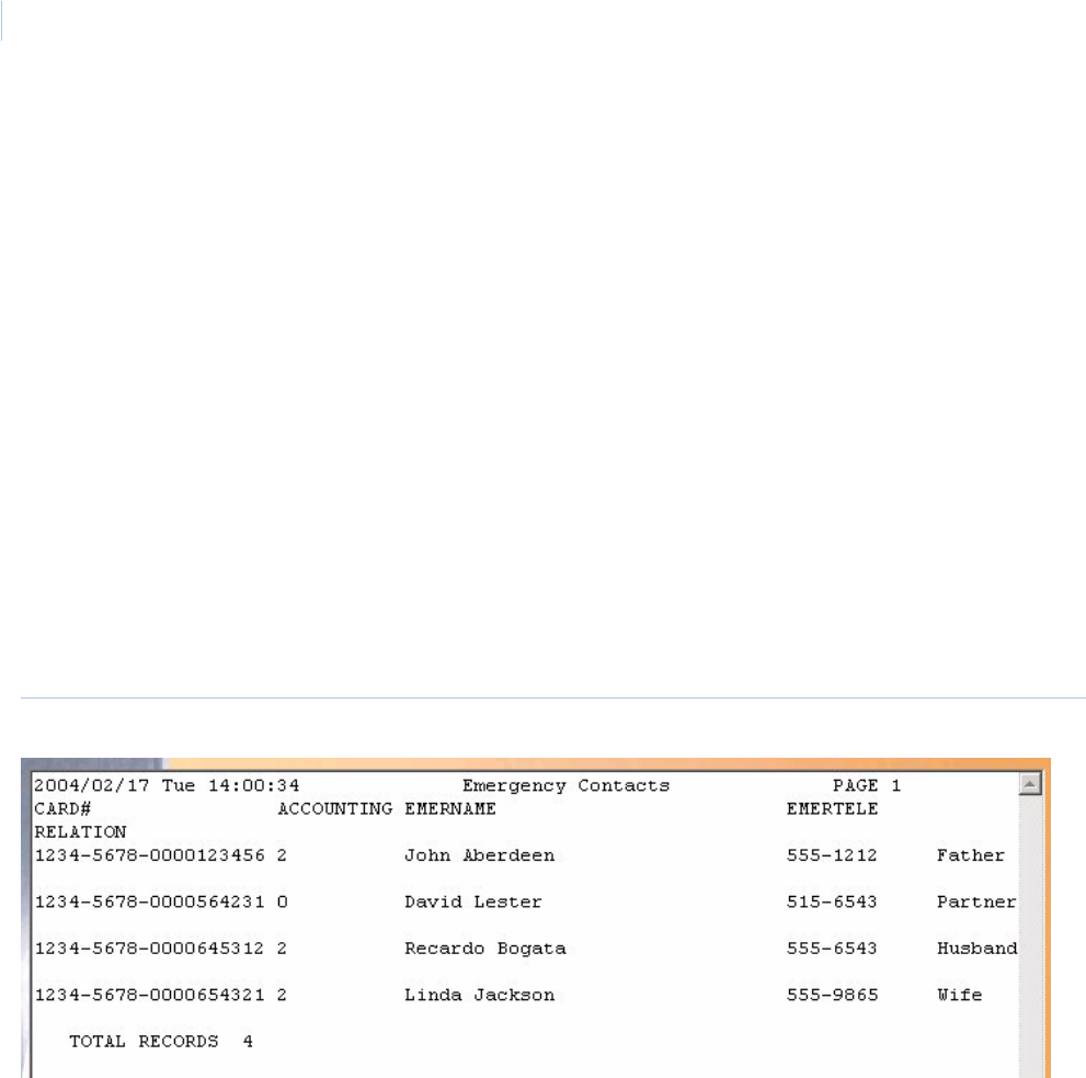
Topa z
User Manual
158
The following is part of an example of an Employee Report, sorted by Employee Name, with fields
Card number, Activation Date, Status, and Access Group 1:
Figure 126.Sample Employee report
Run Report To send the report to the destination you specified above (display, printer, or file), click Run Report in
the bottom right corner of the browser window.
A message “Report Completed” displays, with the number of records printed. Click OK to continue.
If the report does not find any matches for the options that have been entered, the screen returns the
following message “Report Completed, 0 Records Printed”.
Cancel Report To stop the report or when you have finished viewing the report on the monitor, click Cancel Report.
This cancels the operation and returns to the report screen. If no report displays and you click
Cancel, it returns to the Reports page.
Save/Add To save a report you have modified or a new report, click Save/Add.
Note: You must click Save/Add for a newly created report to be saved as a Template to run the
report. If you do not save it and you click Run Report, a report with no records is shown, and
when you click Cancel Report, your changes are lost and the report window closes. Your
changes are erased from the screen.
Delete To delete a report template, select the Template Name and click Delete. The message “Are you sure
you want to delete this record?” displays. Click OK. This deletes that report template from your
computer.
Clear To clear the fields you have entered on this screen, click Clear.

This chapter includes information on how to setup and configure the Topaz
System software.
In this chapter:
Overview. . . . . . . . . . . . . . . . . . . . . . . . . . . . . . . . . . . . . . . . . . 160
Operators Setup Page . . . . . . . . . . . . . . . . . . . . . . . . . . . . . . . 161
Operator Type Page . . . . . . . . . . . . . . . . . . . . . . . . . . . . . . . . . 163
Time Schedule Page . . . . . . . . . . . . . . . . . . . . . . . . . . . . . . . . 166
Security Area Page. . . . . . . . . . . . . . . . . . . . . . . . . . . . . . . . . . 168
Access Group Page . . . . . . . . . . . . . . . . . . . . . . . . . . . . . . . . . 172
Site Settings Page . . . . . . . . . . . . . . . . . . . . . . . . . . . . . . . . . . 175
Custom Fields Page . . . . . . . . . . . . . . . . . . . . . . . . . . . . . . . . . 177
Facility Code Page . . . . . . . . . . . . . . . . . . . . . . . . . . . . . . . . . . 179
Variable Card Page . . . . . . . . . . . . . . . . . . . . . . . . . . . . . . . . . 180
Reader Event Page . . . . . . . . . . . . . . . . . . . . . . . . . . . . . . . . . 187
Alarm Options. . . . . . . . . . . . . . . . . . . . . . . . . . . . . . . . . . . . . . 188
Alarm Instruction Page . . . . . . . . . . . . . . . . . . . . . . . . . . . . . . . 189
Alarm Categories Page . . . . . . . . . . . . . . . . . . . . . . . . . . . . . . 191
Holidays Page . . . . . . . . . . . . . . . . . . . . . . . . . . . . . . . . . . . . . 192
Chapter 8 Setup
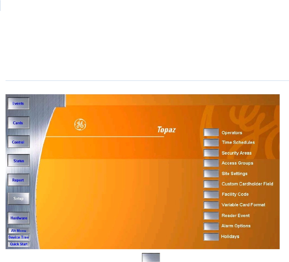
Topa z
User Manual
160
Overview
The Setup pages allow you to setup and configure the Topaz System software.
To navigate to the Setup pages, click the Setup button in the left frame of the browser window to see
the following:
Figure 127.Setup
To navigate to one of the Setup pages, click the button next to the desired page. Each of the
Setup pages is covered in detail on the following pages.
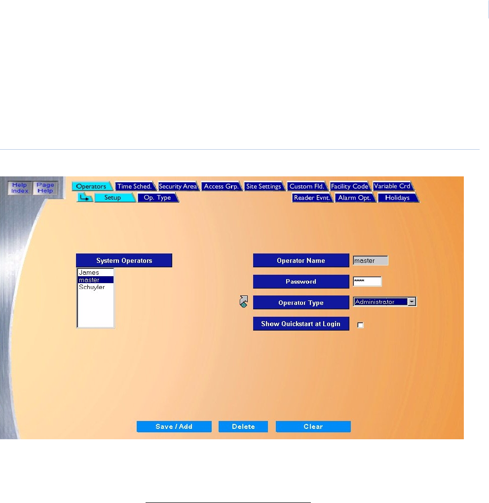
Chapter 8
Setup
161
Operators Setup Page
The Operators page allows you to configure up to 256 operators and assign them 47 different
functions.
To navigate to the Operators page, from any Setup page click the Operators tab button at the top of
the page. The following page displays.
Figure 128.Operators
The Operators Setup page contains the following information:
System Operators A list of all configured operators.
Operator Name Enter the Operator Name (name or nickname) of up to 8 alphanumeric characters. The name is not
case sensitive. You may not duplicate an Operator Name.
Password Enter the operator’s Password of up to 6 alphanumeric characters. In place of the characters typed
for the password, “*” display.
Operator Type Select an Operator Type to assign to the Operator Name and Password by clicking on the Type
Name from the drop-down list of operator types.
Note: Click the link arrow to set up additional Operator Types. When setup has been completed,
close the window by clicking Save and continue working in the Operator Setup page.
Show Quickstart at
Login
Click to place a check mark in the field to show the QuickStart screens when this operator logs onto
the Topaz system.
Topa z
User Manual
162
How to add operators
1. Start by clicking Clear.
2. Enter the Operator Name, the operator’s Password, and an Operator Type.
3. If you want to show the QuickStart screens when this operator logs onto the Topaz system,
click Show Quickstart at Login.
4. Once all entries have been made to the Operators Setup page, click Save. A message
“Operation Complete” displays.
How to modify operators
1. Under System Operators, click and highlight the name of the operator that you wish to
modify.
2. Next, make any desired changes, then click Save. A message “Operation Complete”
displays.
How to delete operators
1. Under System Operators, click and highlight the name of the operator you wish to delete.
2. After verifying that the correct operator to delete is selected, click Delete.
3. A message “Are you sure you want to delete this record?” displays. Click OK to continue.
A message “Operation Complete” displays.
Save/Add Once all data for the new cardholder has been entered, click Save/Add.
After clicking Save one of three messages appears.
• If “Operation Complete” is displayed, no further changes are needed.
• If “Duplicate Record” is displayed, then the operator name has been repeated. Use a new
operator name and try saving again.
• If “Operation Failed” is displayed, then a required field was not entered. Enter the required
information and try saving again.
Delete Click to delete the selected operator record.
CAUTION: Use caution when deleting operators and passwords. Make sure you do not delete the
last password that allows access to setup operators. This could prevent you from accessing vital
features of the software.
Clear At any point, if you wish to clear out all entered information, click Clear.
Clicking Clear before clicking on Save deletes newly entered data.
CAUTION: Use caution when deleting passwords. Make sure you do not delete the last password that allows
access to setup operators. This could prevent you from accessing vital features of the software.
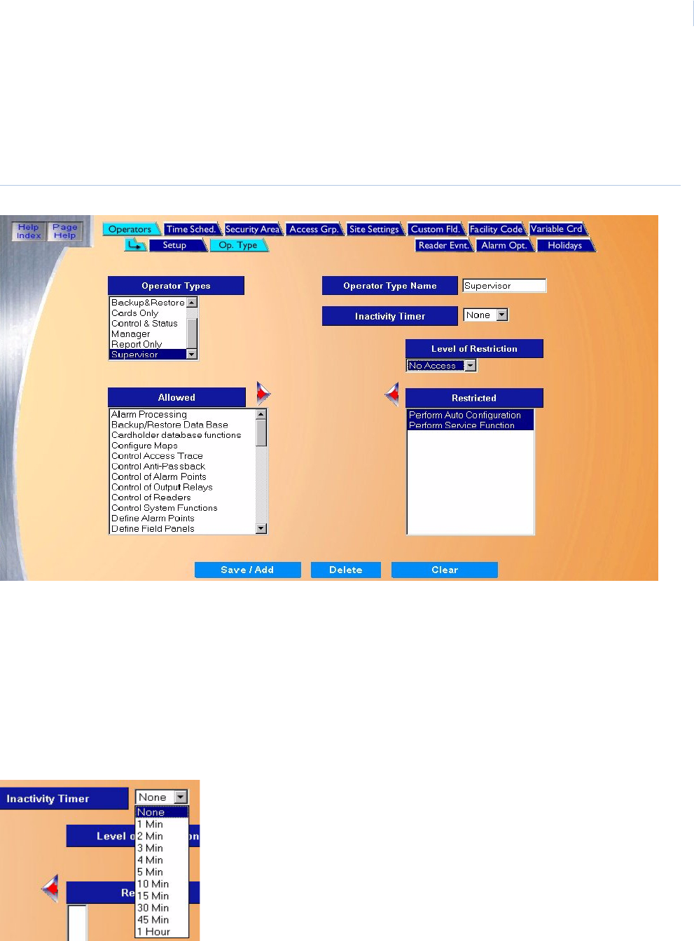
Chapter 8
Setup
163
Operator Type Page
The Operator Type page allows you to configure, add, and assign 47 different functions to 64 types
of operators. To navigate to the Operator Type page, from any Setup page click the Operators tab
button at the top of the window and then the Op. Type tab button. The following page displays.
Figure 129.Operator Type
The Operator Type page contains the following information:
Operator Types This is a list of Operator Types that has already been configured. To select a
configured operator type from the list, scroll through the list to locate the operator type
you wish to use. Click the Operator Type Name to select. The list of Restricted
functions for the operator type selected appears.
To modify the list and save it as a new operator type, enter a new Operator Type Name
into the field and click Save. See How to modify an operator type on page 165 for
detailed information on how to modify and save the list.
Operator Type Name Enter the Operator Type Name of up to 16 alphanumeric characters.
Inactivity Timer The Inactivity Time tracks keyboard activity to log off the operator.
When an operator logs on to the system, the timer (if set to a time rather than NONE)
begins counting. Each time the operator uses the keyboard or mouse, the timer resets.
If the timer counts up to the time set in the Inactivity Timer field, the current operator is
logged off the system.
The Inactivity Timer is selectable for each Operator Type independently. The default is
None.

Topa z
User Manual
164
Level of Restriction If one or more functions are listed under Restricted, the Level of Restriction field
displays. There are two choices for level of Restriction:
No Access – That Operator Type cannot access or view any information on that
function screen. The default restriction for a new Operator Type is “No Access”.
Display Only – That Operator Type can view the information on that function screen but
cannot add, modify, or delete any of the information.
• To change the Level of Restriction, click the function to be modified on the
Restricted list. The current Level of Restriction for the function appears in the
Level of Restriction field. Click the down arrow to see the choices, as shown
below, and click the level you want for the function(s).
• You can set the same Level of Restriction for many functions at the same time, by
selecting the functions and then selecting a Level of Restriction to be applied to all
selected functions. You can select more than one function with SHIFT-Click or
CTRL-Click as described above.
• You can set a different Level of Restriction for each function. For example, you can
set “Display Only” for the “Cardholder database functions”, and set “No Access“for
the “Control Anti-Passbook” function.
Allowed The Allowed field is the list of all 47 functions that can be assigned to the Operator
Type (when you click Save). For a new Operator Type, by default, all functions are
listed under Allowed.
If you want to restrict an Operator Type to have limited use of a function:
Select the function under Allowed by clicking on it. If you want to select more than one
function at a time, you can use these shortcuts:
• Shift-Click – If you click one function and move the cursor to another function, and
then press the SHIFT key and click, you can select ALL functions from the first to
the second.
• CTRL-Click – If you press the CTRL key and click one function, you can select or
unselect it.
Click the right arrow to move that function to the Restricted list. Then change its Level
of Restrictions as described above.
For a list of operator functions, seeAppendix E, Operator Type Functions.
Restricted If you want to remove the restrictions from a function, to make that function fully
allowed:
Select the function under Restricted by clicking on it. If you want to select more than
one function at a time, you can use these shortcuts:
• Shift-Click – If you click one function and move the cursor to another function, and
then press the SHIFT key and click, you can select ALL functions from the first to
the second.
• CTRL-Click – If you press the CTRL key and click one function, you can select or
unselect it.
Click the left arrow to move that function to the Allowed list.
Save/Add Once all data for the new cardholder has been entered, click Save/Add.
After clicking Save, the “Operation Complete” message displays.
Delete Click to delete the selected operator record.
CAUTION: Use caution when deleting operators and passwords. Make sure you do
not delete the last password that allows access to setup operators. This could
prevent you from accessing vital features of the software.
Clear At anytime click Clear to clear the Operator Type Name field and reset all Functions
back to the Allowed list.

Chapter 8
Setup
165
How to add an operator type
1. Start by clicking Clear.
2. Enter the Operator Type Name of up to 16 alphanumeric characters.
3. Enter the Inactivity Time.
4. Using the Allowed field, if desired restrict the functions that this operator type can perform.
5. Select the Level of Restrictions, No Access (the default) or Display Only.
6. Click Save/Add.
How to modify an operator type
1. Click the name for the Operator Type in the list that you wish to modify. A list of operator
functions is listed under Allowed. The Restricted list on the right shows any restricted
functions set for that Operator Type.
2. You can move functions to the Allowed or Restricted lists and set a new Level of
Restriction.
3. Click Save/Add.
How to delete an operator type
1. Click the name for the Operator Type in the list that you wish to delete so that it is highlighted.
The Operator Type Name displays.
2. Click Delete.
3. A message “Are you sure you want to delete this record?” displays. Click OK to continue.
A message “Operation Complete” displays.
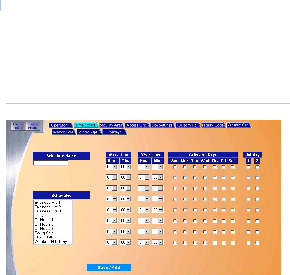
Topa z
User Manual
166
Time Schedule Page
The Time Schedule page allows you to configure time frames to link to functions within Topaz. For
example, you can configure a Time Schedule to automatically lock, and unlock doors, mask alarms
during business hours, or to turn on the parking lot lights.
To navigate to the Time Schedule page, from any Setup page click the Time Schedule tab button at
the top of the page, or from the main Setup page click the Time Schedules button on the right side
of the page. The following page displays.
Figure 130.Time Schedules
The Time Schedule page contains the following information:
Schedule Name Enter up to 16 alphanumeric characters. For example, “07:00-16:00 M-F” (Military time, meaning that
the time schedule covers from 7am to 4pm Monday through Friday) or “Work Hrs”. Military time is
sometimes referred to as a 24 hour clock shown in the chart below. For example, 11:50pm would be
23:50
Schedules You can select a currently configured Time Schedule from the Schedules list. By clicking on a Time
Schedule in the list you can see the start and stop time, days of the week, and holiday type for which it
is set. You can also use this selection to pick an existing Time Schedule that is similar to one you want
to add, then change its Schedule Name and other fields.
Note: A maximum of 127 Time Schedules may be configured on the Topaz System.
Start Time Select the time frames that the schedule covers, by clicking on the down arrow to the right of the first
field selection (the hour). Then click the number of the start hour from the drop-down list 1-23. Select
the minutes (00-59) the same way.
Stop Time Set the ending time for the schedule.

Chapter 8
Setup
167
How to add a new time schedule
1. Enter a Schedule Name. For example, “07:00-16:00 M-F” (Military time, meaning that the
time schedule covers from 7am to 4pm Monday through Friday) or “Work Hrs”. Military time is
sometimes referred to as a 24 hour clock shown in the chart below. For example, 11:50pm
would be 23:50.
You can also select an existing Time Schedule that is similar to one you want to add, then
change its Schedule Name and other fields.
2. Select a Start Time, Stop Time, and the days of the week that the schedule is active.
3. If you need additional time segments in this schedule, you can define them in the additional
rows below. For example, you may want the schedule to be active 07:00-16:00 (7am – 4pm)
Monday - Friday and on Saturday from 10:00-15:00 (22:00 – 17:00). Do this in the second set
Active on Days Select the days of the week that the schedule is active. Do this by clicking each box to add a check
mark for each day of the week you want the schedule to be active.
Note: You may need to use more than one setting of Start Time, Stop Time, and Active on Days for
shifts that occur over midnight or over time schedules. For example, if you are configuring the
times for a shift that works from 10pm to 6am, you will have to set two time segments. The
first should be for 10pm to midnight (22:00 - 23:59) Sunday through Thursday and the second
one for midnight to 6am (00:00 - 06:00) Monday through Friday.
Note: A maximum of 8 time segments can be configured for one Time Schedule.
Holiday Select if the schedule is used on a holiday. Select Holiday 1 and/or 2. For more information on
holidays, see Holidays Page on page 192.
Save/Add Once all data for the new cardholder has been entered, click Save/Add.
After clicking Save the “Operation Complete” message displays.
AM 24 Hour PM 24 Hour
1am 1:00 Hrs. 1pm 13:00 Hrs.
2am 2:00 Hrs. 2pm 14:00 Hrs.
3am 3:00 Hrs. 3pm 15:00 Hrs.
4am 4:00 Hrs. 4pm 16:00 Hrs.
5am 5:00 Hrs. 5pm 17:00 Hrs.
6am 6:00 Hrs. 6pm 18:00 Hrs.
7am 7:00 Hrs. 7pm 19:00 Hrs.
8am 8:00 Hrs. 8pm 20:00 Hrs.
9am 9:00 Hrs. 9pm 21:00 Hrs.
10am 10:00 Hrs. 10pm 22:00 Hrs.
11am 11:00 Hrs. 11pm 23:00 Hrs.
Noon 12:00 Hrs. Midnight 00:00 Hrs.
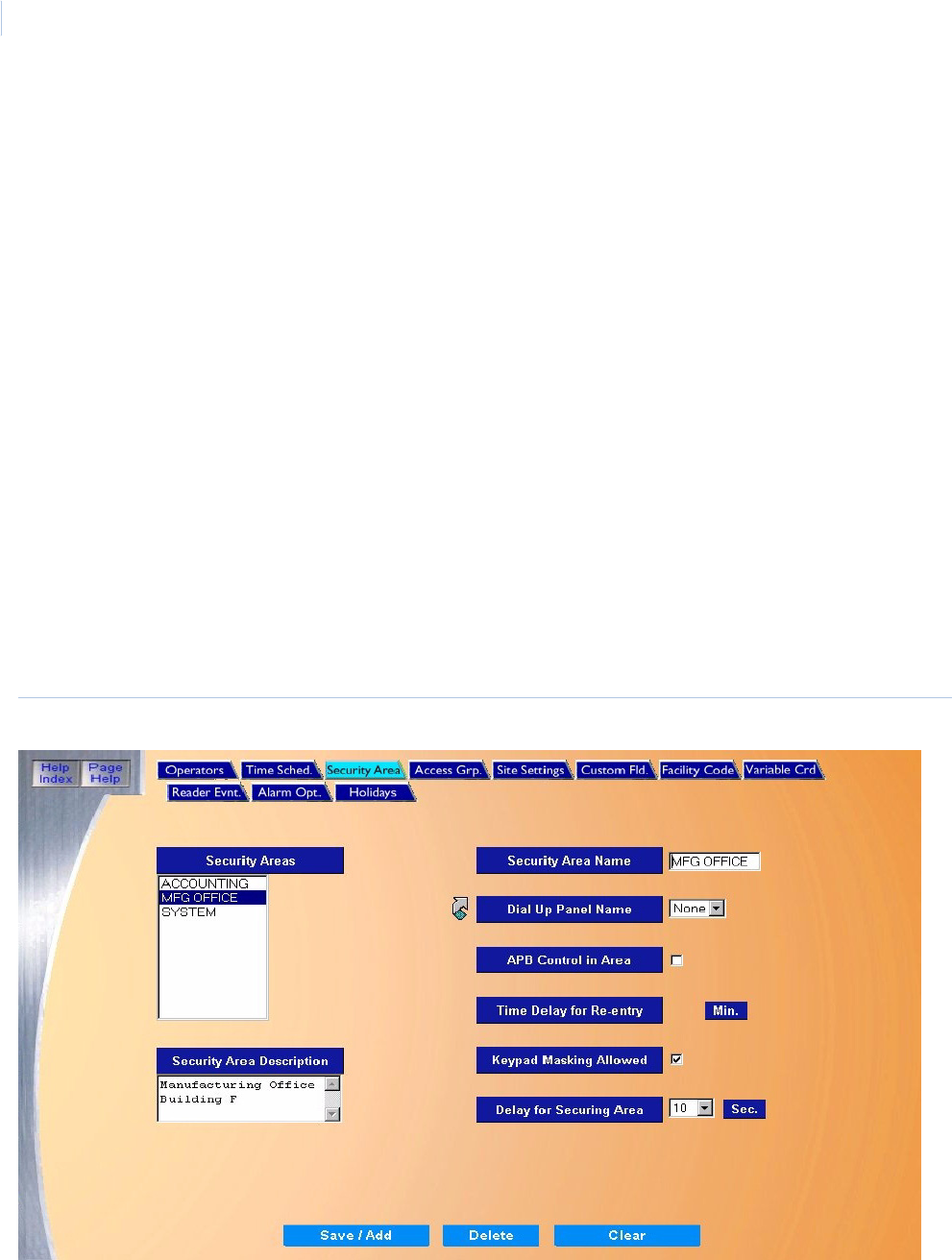
Topa z
User Manual
168
of schedule parameters. A maximum of 8 time segments can be configured for one Time
Schedule.
4. When all fields have been set correctly, click Save/Add. A message “Operation Complete”
displays.
How to modify a time schedule
1. Select the Time Schedule to be modified by clicking on the Schedule Name list. Once
highlighted in the list, you can see the times and days it is set for.
2. The name that was selected above under Schedules displays in this field. Make desired
changes to the name, times and/or days of the week.
3. After making all desired modifications to the Time Schedule, click Save/Add. A message
“Operation Complete” displays.
Security Area Page
The Security Area ‘page allows you to add a new security area or modify or delete an existing one.
To navigate to the Security Area page, from any Setup page click the Security Area tab button at
the top of the window, or from the main Setup page click the Security Areas button on the right side
of the page. The following page displays.
Figure 131.Security Area

Chapter 8
Setup
169
The Security Area page contains the following information:
How to add a new security area
1. Start by clicking Clear. All fields reset and allow adding of the new area.
Security Areas A list of all configured security areas.
Security Area Description Enter up to 80 alphanumeric characters for the description of the security area being
configured.
Security Area Name Enter up to 12 alphanumeric characters for the name for the security area being
configured. This is the name that assigned to devices that are associated with the area.
Dial Up Panel Name If the Security Area is associated with devices connected to an ACU panel that
communicates through Dialup, then select the panel name from the drop-down list.
Note: Click the link arrow to set up additional Dial-up Panels. When setup has been
completed, close the window by clicking Save and continue working in Security
Area setups.
APB Control in Area If the area is controlled by Anti-Passback, then select APB Control in Area by clicking the
box to the right.
Unchecked – Default. This Security Area does not use Anti-Passback.
Checked - This Security Area responds to APB violations with an alarm event. If
checked, you are presented with the choice for Timed Delay for Reentry (in minutes).
For more information on Anti-Passback, see Appendix C, Anti-Passback.
Time Delay for Re-entry For Time Delay for Re-entry, if Anti-Passback is being used in the security area, then you
can select the delay in minutes before the cardholder is allowed to access the area again
after access has been granted. The minutes must be positive whole numbers, not
decimals.
This is used to discourage passing a card back to another person to follow you into a
security area with only one reader, such as a parking lot or turnstile. Once a card is used
on an entry reader, any attempt to use the same card on any other entry reader assigned
to the same area before that time expires generates an APB violation alarm and access
is denied until the total time has expired.
There are two ways to reset the delay time for a given reader:
• If the card is used at another reader outside that area.
• If the time delay expires.
For more information on Anti-Passback, see Appendix C, Anti-Passback.
Keypad Masking Allowed Select this option if you want the cardholder to be allowed to mask alarms. Masking
means that alarms for that area are turned off.
For more information, see How to use keypad masking on page 171.
Delay for Securing Area If the Security Area uses the Delayed Alarm Reporting and Masking option, select the
number of seconds that the alarms should wait before reporting the alarm state. This
allows time for the authorized cardholder to mask the alarms.
Save/Add Once all the data for the new cardholder has been entered, click Save/Add.
After clicking Save the “Operation Complete” message displays.
Delete After selecting the Security Area to delete, click Delete to remove the record from the
database.
CAUTION: Before deleting a security area, remove the area from all cardholders and
move all alarms and readers from the area to be deleted.
Clear At any point if you wish to clear out all entered information, click Clear to reset all fields.

Topa z
User Manual
170
2. Enter the Security Area Name and Security Area Description
3. If the Security Area is associated with devices connected to an ACU panel that
communicates through Dialup, select a Dial-up Panel Name.
4. If the area is controlled by Anti-Passback, select APB Control in Area and Time Delay for
Re-entry.
5. Select Keypad Masking Allowed if you want the cardholder to be allowed to mask alarms.
Masking means that alarms for that area are turned off.
6. If the Security Area uses using the Delayed Alarm Reporting and Masking option, select the
number of seconds that the alarms should wait before reporting the alarm state. This allows
time for the authorized cardholder to mask the alarms.
7. Once all information has been added to the Security Areas page, click Save. A message
“Operation Complete” displays.
How to modify an existing security area
1. From the Security Area list scroll through and select the Security Area to modify by clicking
on the area name to be modified. After a name is selected, the current configuration displays
in the fields on the page.
2. Make any desired changes to the rest of the fields.
3. Click Save.
How to delete a security area
1. From the Security Areas list select the Security Area to delete by clicking on the name. After
a name is selected (highlighted), the current configuration displays in the other fields on the
page.
2. After checking to making sure the correct area is selected click Delete.
3. A message “Are you sure you want to delete this record?” displays. Click OK to continue.
A message “Operation Complete” displays.
CAUTION: Before deleting a security area, remove the area from all cardholders and move all alarms and readers
from the area to be deleted.

Chapter 8
Setup
171
How to use keypad masking
Configuration
Keypad Masking requires three conditions to be set, in the following order:
1. Under Setup – Security Areas, click the area name under Security Areas, to place the name
under Security Area Name. Then select the check box next to Keypad Masking Allowed.
2. To mask any alarms, the cardholder must first be allowed access into that Security Area.
Under Cards – Access, select the cardholder, then the area under Available Security Areas
and move that area to the Selected Security Areas column.
3. The cardholder must have that Masking Security area selected. Under Cards – Masking,
move the area from Available Masking Areas to Selected Masking Areas.
4. Click Save.
Operation
1. To use the keypad to unsecure an area, the cardholder must enter the PIN + 20 to mask the
alarm. For example, if the PIN is 1023, the cardholder enters 1043 to mask that security area.
The alarms will be turned off and the door will unlock.
Note: No access is granted until the alarms are masked.
If one cardholder unmasks the alarms, anyone with access to that area can enter. The alarm will be off.
2. To secure the area, the cardholder must enter the PIN + 10 to unmask the alarm. For
example, if the PIN is 1023, the cardholder enters 1033 to unmask that security area. The
alarms will then be set (on).
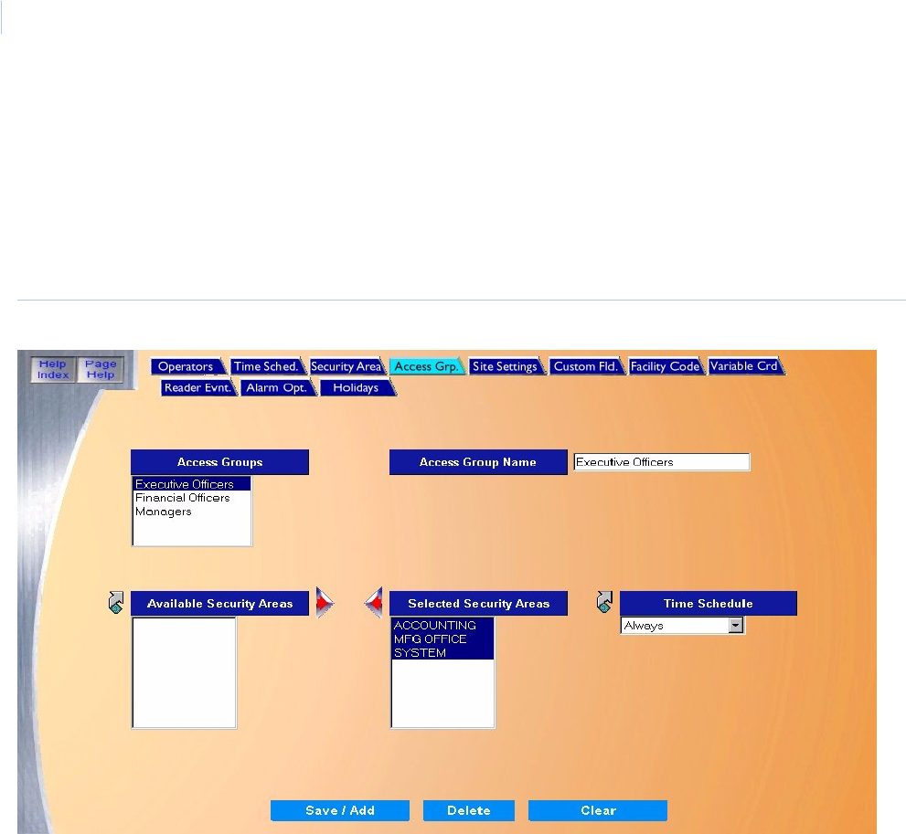
Topa z
User Manual
172
Access Group Page
The Access Group page allows you to add one or more Security Areas to an Access Group and
define the Time Schedule to each area.
To navigate to the Access Group page, from any Setup page click the Access Grp. tab button at
the top of the page, or from the main Setup Page click the Access Groups button on the right side of
the screen. The following page displays.
Figure 132.Access Group
The Access Group page contains the following information:
Access Groups A list of all configured access groups.
Access Group Name Enter up to 28 alphanumeric characters for the description of the access group being configured.
Available Security Areas A list of Security Areas that are available for selection. Select a Security Area to add to the
access group by scrolling through the list and clicking on the name of the area so it is
highlighted.
Selected Security Areas A list of Security Areas that have been selected for the access group.
Time Schedule A drop-down list of pre-configured time schedules to choose from. The default Time Schedule for
all areas selected is Always.
Note: Click the link arrow to set up a additional Time Schedules. When setup has been
completed, close the window by clicking Save.

Chapter 8
Setup
173
How to add a new access group
1. Start by clicking Clear to clear all fields.
2. Enter the Access Group Name of up to 28 alphanumeric characters.
3. In the Available Security Areas list, select a Security Area to add to the group by scrolling
through the list and clicking on the name of the area so it is highlighted.
4. Click the right arrow to move the Security Area to the Selected Security Areas list. Repeat
the above steps until all desired areas have been added to the Selected Security Areas list.
If you move the wrong security area, you can move it back by clicking on the left arrow.
5. If desired, select a Time Schedule for any given Security Area.
6. Once all Access Group data has been entered, click Save/Add.
How to modify an access group
1. Select the access group to modify by scrolling through the Access Groups list and click the
name of the access group. Once the name of the Access Group to modify is highlighted, the
security areas assigned to the selected access group are listed in the Selected Security
Areas list.
2. If you want to rename an Access Group:
a. Select the access group to rename by scrolling through the Access Group list and click
the name of the access group.
b. Make the required changes to the name in the Access Group Name field.
3. If you want to add or remove a Security Area in an Access Group:
a. Add another area by selecting the security area name in the Available Security Areas list
and click the right arrow to move the area to the Selected Security Area list.
b. Remove an area from the list by clicking on the area in the Selected Security Areas list
then click the left arrow to move the area out of the selected area list.
4. If you want to modify the Time Schedule For Security Areas:
Save/Add Once all data for the new cardholder has been entered, click Save/Add.
After clicking Save one of the following messages appears.
• If “Operation Complete” is displayed, then no further changes are needed
• If “Duplicate Record” is displayed, then the Access Group Name has been repeated. Use a
new name and try saving again.
• If “Operation Failed” is displayed, then a required field was not entered. Enter the field and
try saving again.
Delete After selecting the Access Group to delete, click Delete to remove the record from the database.
CAUTION: DO NOT delete an Access Group until all cardholders have been deleted from the
group.
Clear At any point if you wish to clear out all entered information and start over, click Clear.
CAUTION: Clicking Clear before clicking Save deletes newly entered data.

Topa z
User Manual
174
a. Click the security area name to modify under Selected Security Areas.
b. Then select the new Time Schedule from the drop-down list and click the desired time
schedule.
5. Once all changes have been made to the Access Group, click Save/Add.
How to delete an access group
1. Select the access group to delete by scrolling through the Access Group list and click the
name of the access group to delete.
2. Once the name of the access group to delete is highlighted, click Delete.
3. After clicking Delete the message “Are you sure you want to delete this record?” appears.
Click OK to continue.
4. The Access Group name is removed from the list.
The message “Operation Complete” should display and the Access Group name is
removed from the list.
CAUTION: DO NOT delete an Access Group until all cardholders have been deleted from the group.
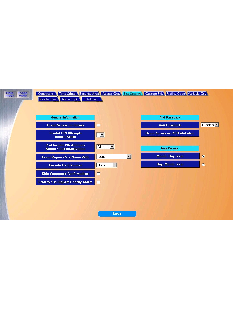
Chapter 8
Setup
175
Site Settings Page
The Site Settings page allows you to configure various settings applicable to your site.
To navigate to the Site Settings page, from any Setup page click the Site Settings tab button at the
top of the window, or from the main Setup Page click the Site Settings button on the right side of the
screen. The following page displays.
Figure 133.Site Settings
The Site Settings page contains the following information:
Grant Access on Duress The default is no selection, meaning no access is granted if the cardholder generates
a Duress alarm with the PIN. A cardholder uses the Duress feature by swiping the
card (which tells the system the card number) and then enters the PIN number with
five added to it. For example, if the PIN is 1234, the Duress PIN would be 1239.
If you wish to allow access when the cardholder causes a Duress Alarm (providing the
cardholder would normally be authorized access to the area), then click the box next
to the selection, to place an X in it.
For more information, see Duress on page 391.
Invalid PIN Attempts Before Alarm Set the number of times (1 through 9) a cardholder may enter the wrong PIN before
the alarm “ACCESS DENIED - WRONG KEYPAD - TOO MANY ATTEMPTS” is
generated. The default for this field is 3.
Note: The system is set to generate an alarm every time a wrong PIN is entered. If
you do not want an alarm for each wrong PIN, modify a different alarm on the
Reader Events page (see page page 187). Select “ACCESS DENIED -
WRONG KEYPAD” and in the field beside Acknowledgment select “NO”.

Topa z
User Manual
176
# of Invalid PIN Attempts Before
Card Deactivation
Set the number of times a cardholder may enter the wrong PIN before their card is
deactivated. The default is Disabled and the possible selections are 1 through 9 times.
Note: If a card has been deactivated, before it can be activated again, you must
change the deactivation date in the cardholder record to make the card valid
again.
Event Report Card Name With • None (default)
• Employee Number - Anytime the cardholder name is displayed or printed, the
Employee Number accompanies it.
• Card Number - Anytime the cardholder name is displayed or printed, the Card
Number accompanies it.
Encode Card Format This optional field defines the format the photo printer uses to encode the cards during
printing. Options are None, or Format 1 through Format 15. For more information, see
the section Variable Card Page on page 180.
Note: The printer being used must support this feature.
Skip Command Confirmations The default is to have command executions confirmed with the message “Operation
Complete” after execution. You must click OK to continue. If you do not want
command confirmations displayed, click the white box next to the selection, to place
an X in it.
Priority 1 is Highest Priority Alarm This setting enables 1 to be the highest priority alarm. It then displays at the top of the
Alarm Queue window regardless of when it was received. When unchecked “16” is the
highest priority alarm and displays at the top of the Alarm Queue.
Note: The default for this field is unchecked (16 is the highest priority). This should
be kept in mind when assigning priorities to alarm points. See Priority on
page 246.
Anti-Passback Set this to Enabled if Anti-Passback is used by Topaz.
• Disabled - Default. The Anti-Passback feature is not used.
• Enabled - The Anti-Passback feature is used and you are presented with the
choice for Grant Access on APB Violation.
For more information on Anti-Passback, seeAppendix C, Anti-Passback.
Grant Access on APB Violation This field is only accessible if you select Enabled for the Anti-Passback field.
• Unchecked - Any card swipe that activates an APB violation results in the
cardholder being denied access and triggers an alarm APB violation event. The
alarm event notifies the security operator, who may want to send somebody to
that security area.
• Checked - Any card swipe that activates an APB violation results in the
cardholder being allowed access and triggers an APB violation event. This is not
normally used, but may be helpful for testing Topaz.
For more information on Anti-Passback, seeAppendix C, Anti-Passback.
Date Format You can choose from one of two formats for the date:
• Month, Day, Year (default) - The date displays in this format, for example, Jan 13,
2000.
• Day, Month, Year - The date displays in this format, for example, 13 Jan 2000.
Select one of the above date formats by clicking on the white circle next to the
selection, to place a black dot in it.
Save Once all changes have been made to the Site Settings page, click Save.
After clicking Save, the “Operation Complete” messages displays.
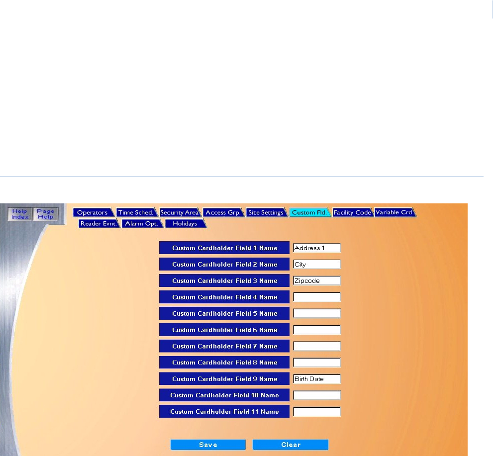
Chapter 8
Setup
177
Custom Fields Page
The Custom Fields page allow you to custom design 11 fields for any data field needed on a
cardholder, in addition to the default fields in the cardholder database. For example, you can add
Address, Emergency Notification, etc.
To navigate to the Custom Fields page, from any Setup page, click the Custom Fld. tab button at
the top of the window, or from the main Setup Page click the Custom Cardholder Field button on
the right side of the screen. The following page displays.
Figure 134.Custom Fields
The Custom Field page contains the following information:
Custom Cardholder Field 1
through 11 Name
This page allows you to customize the label/name of these fields as they appear in the
cardholder database. When deciding which label to use for each Custom Field, remember
the maximum size allowed in each field as shown below.
• User Field 1 - 4 can contain a maximum of 24 alphanumeric characters.
• User Field 5 - 7 can contain a maximum of 16 alphanumeric characters.
• User Field 8 - 11 can contain a maximum of 12 alphanumeric characters.
Once the new label/name has been entered on this page, the cardholder information which
fits the custom field, can be entered on the Custom Fields Page on page 69.
Save Click Save to save the custom field to the cardholder database. A message “Operation
Complete” displays.
Clear At any point if you wish to Clear out all entered information and start over, click Clear.
Note: If Clear is clicked before you click Save, any changes to fields or are lost. Click
another page button and then back on Custom Fld. This redisplays the original
field names that were saved.

Topa z
User Manual
178
How to add a custom field
1. You add a field by entering the name (up to 12 alphanumeric characters) in one of the
available blank fields on this page.
2. Click Save. A message “Operation Complete” displays and new names appear in the
Cardholder page as new field names.
How to modify a custom field
1. You modify an existing name by changing the text in the field (up to 12 alphanumeric
characters).
2. Once the text in the fields appears as desired, click Save.
A message “Operation Complete” displays and any new names now appear in the
Cardholder page as new field names.
How to delete custom fields
You cannot delete the custom field label/name. All you can do is change the names of those fields.
Any information entered on a cardholder screen for a given custom field is stored in that field
permanently, or until you erase the information on a cardholder screen.
CAUTION: You may rename a field at anytime, but the data already entered will not move with the field name. For
example, if a field is named Address and you have entered address information into that field in the Cardholder
page and then rename the field to License Number. The address information will still reside under the same field
now with the new name of License Number.
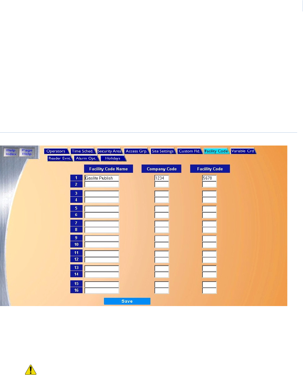
Chapter 8
Setup
179
Facility Code Page
The Facility Code page allows you to enter as many as 16 Facility/Company Codes for different sets
of cards. The Company Code and Facility Code are a set of numbers encoded into the access card
that the system uses to identify which site the cardholder is from. When you purchase cards, you
receive a particular company code for the set. When you purchase additional sets of cards, it is
almost certain that the cards (unless you special order them) have a different company code. You
configure a new facility and company code for the new set of cards.
To navigate to the Facility Code page, from any Setup page click the Facility Code tab button at the
top of the window, or from the main Setup page click the Facility Code button on the right side of the
page. The following page displays.
Figure 135.Facility Code
The Facility Code page contains the following information:
Facility Code
Name
Enter up to 15 alphanumeric characters for the name of the card set. The Company and Facility Code
numbers can also be used as the name.
Company Code Enter up to 4 digits for the Company Code. For 26 bit card format, the facility code must be entered into
the Company Code field and the facility code field is set to 0.
Facility Code Enter up to 4 digits for the Facility Code.
CAUTION: The Company Code and Facility Code must match the numbers encoded on the access
cards. or the cards will not work properly.
Note: The Facility Code on HID cards is the equivalent of the Company Code in Topaz. For example, if
the HID facility code is 112, you would enter 112 in Company Code and 0 in Facility Code.
Save Once all changes have been made to the Facility Codes page, click Save. After clicking Save, the
“Operation Complete” messages displays.
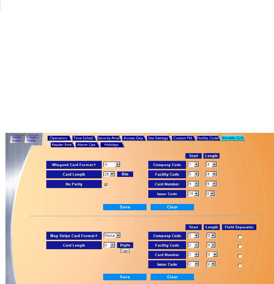
Topa z
User Manual
180
Variable Card Page
The Variable Card Page allows you to configure the system to accept card formats other than the
pre-defined standard formats normally supported. This provides wider flexibility in the use of existing
cards.
Custom Card Formats are used when upgrading readers without having to change the existing card
technology at a site. By entering the bit location and length in each of the code fields, a card format is
created that is then assigned to one or more readers. You can define up to 15 Wiegand and 15 Mag
Stripe Card custom formats.
To navigate to the Variable Card page, from any Setup page click the Variable Crd tab button at the
top of the window, or from the main Setup page click the Variable Card Format button on the right
side of the page. The following page displays.
The Variable Card page contains the following information:
Wiegand Card Format # Cards with the Wiegand Card Format are usually ordered pre-coded with information (company
code, facility code, and card number). Most Topaz installations do not require a format change. If
you do wish to change the format you are using, you can do so with this screen. See How to add
a card format on page 182.
Wiegand Card Formats are defined in terms of bits (a bit is either zero or one)
Card Length Select from 1 to 63 bits for the Card Length. Most Topaz installations use a 37-bit format. Another
popular Wiegand Card Format is a 26-bit format.
No Parity The default is to use parity. You may turn parity off by selecting No Parity, to place a check mark
in the box.
Company Code • Start - Select the location of the first bit for the Company Code as the Start value. For the
normal Topaz installation, the Start value is 2, meaning the Company Code starts in the
second bit in the string of bits. For a Start value, select from 1-64 bits.
• Length - The Length is the number of bits to use for the Company Code. For a length, select
a value from 0-16 bits.

Chapter 8
Setup
181
Facility Code • Start - Select the location of the first bit for the Facility Code as the Start value. For a Start
value, select from 1-64 bits.
• Length - The Length is the number of bits to use for the Facility Code. For a length, select a
value from 0-16 bits.
Card Number • Start - Select the location of the first bit for the Card Number as the Start value. For a Start
value, select from 1-64 bits.
• Length - The Length is the number of bits to use for the Card Number. For a length, select a
value from 0-36 bits.
Issue Code The Issue Code is not used in the Wiegand format unless you have the ability to encode your
own cards. The Issue Code is normally 1 digit.
• Start - Select the location of the first bit for the Issue Code as the Start value. For a Start
value, select from 1-64 bits.
• Length - The Length is the number of bits to use for the Issue Code. For a length, select a
value from 0-8 bits.
Mag Stripe Card Format #Unlike a Wiegand Card Format, which cannot be changed for a given card, Mag Stripe Cards
can have their data changed. However, this requires the use of special equipment, which may or
may not have been part of your site’s installation of Topaz.
Whereas Wiegand cards are formatted in bits, Mag Stripe cards are formatted in digits (0 through
9).
Card Length Select from 1 to 40 bits for the Card Length. Most Topaz installations use a 3-2-6-1 format and
use 14 digits. Another Mag Stripe Card Format is the 4-4-10-2 format, which uses 22 digits. In
both formats, the first and last digits are used as a Begin digit (B) and a Finish digit (F). B is the
Start digit and F is the Stop digit.
Company Code • Start - Select the location of the first bit for the Company Code as the Start value. For a Start
value, select from 2-40 bits.
• Length - The Length is the number of digits to use for the Company Code. For a length,
select a value from 0-4 digits.
• Field Separator - Most cards do not use a Field Separator. It is most commonly used when
compatibility is required with Time and Attendance programs and other systems. When you
select a Field Separator, Topaz uses the letter D. If you want to use a Field Separator, click
the box to the right of the field. Topaz ignores the Field Separator digit in counting where
data fields start.
Facility Code • Start - Select the location of the first bit for the Facility Code as the Start value. For a Start
value, select from 2-40 bits.
• Length - The Length is the number of digits to use for the Facility Code. For a length, select
a value from 0-10 digits.
• Field Separator - Most cards do not use a Field Separator. It is most commonly used when
compatibility is required with Time and Attendance programs and other systems. When you
select a Field Separator, Topaz uses the letter D. If you want to use a Field Separator, click
the box to the right of the field. Topaz ignores the Field Separator digit in counting where
data fields start.
Card Number • Start - Select the location of the first bit for the Card Number as the Start value. For a Start
value, select from 2-40 bits.
• Length - The Length is the number of digits to use for the Card Number. For a length, select
a value from 0-16 digits.
• Field Separator - Most cards do not use a Field Separator. It is most commonly used when
compatibility is required with Time and Attendance programs and other systems. When you
select a Field Separator, Topaz uses the letter D. If you want to use a Field Separator, click
the box to the right of the field. Topaz ignores the Field Separator digit in counting where
data fields start.

Topa z
User Manual
182
How to add a card format
Wiegand Card Formats
Cards with the Wiegand Card Format are usually ordered pre-coded with information (company
code, facility code, and card number). Most Topaz installations do not require a format change. If you
do wish to change the format you are using, you can do so with this screen.
Wiegand Card Formats are defined in terms of bits (a bit is either zero or one).
To add a Wiegand Card Format:
1. Select from the drop-down list of Wiegand Card Format #s. Once a record is selected, the
screen displays the remaining fields for this format.
2. Select the Card Length.
3. If desired, you may turn parity off by selecting No Parity.
4. Select the Start value and Length for the Company Code, Facility Code, and the Card
Number.
5. Click Save.
Issue Code The Issue Code is normally 1 digit and is set to 1. You can use an Issue Code for replaced cards,
etc.
• Start - Select the location of the first bit for the Issue Code as the Start value. For a Start
value, select from 2-40 bits.
• Length - The Length is the number of digits to use for the Issue Code. For a length, select a
value from 0-2 digits.
• Field Separator - Most cards do not use a Field Separator. It is most commonly used when
compatibility is required with Time and Attendance programs and other systems. When you
select a Field Separator, Topaz uses the letter D. If you want to use a Field Separator, click
the box to the right of the field. Topaz ignores the Field Separator digit in counting where
data fields start.
Save Once all changes have been made to the Variable Card page, click Save.
After clicking Save, the “Operation Complete” messages displays.
Clear At any point if you wish to clear out all entered information and start over, click Clear.
Table 8. Example of a 26-bit Wiegand Card Format with no company or facility code
Field Start Length
Company Code 2 0
Facility Code 2 0
Card Number 10 16
Issue Code 2 0
Table 9. Example of a 26-bit Wiegand Card Format with a company but no facility code
Field Start Length
Company Code 2 8
Facility Code 2 0
Card Number 10 16
Chapter 8
Setup
183
Mag Stripe Card Formats
Unlike a Wiegand Card Format, which cannot be changed for a given card, Mag Stripe Cards can
have their data changed. However, this requires the use of special equipment, which may or may not
have been part of your site’s installation of Topaz.
Whereas Wiegand cards are formatted in bits, Mag Stripe cards are formatted in digits (0 through 9).
To add a Mag Stripe Card Format:
1. Select the Card Length.
2. Select the Start value and Length for the Company Code, Facility Code, Issue Code, and the
Card Number.
3. Most cards do not use a Field Separator. It is most commonly used when compatibility is
required with Time and Attendance programs and other systems. When you select a Field
Separator, Topaz uses the letter D. If you want to use a Field Separator, click the box to the
right of the field. Topaz ignores the Field Separator digit in counting where data fields start.
See the example below.
Issue Code 2 0
Table 10. Example of a 34-bit Wiegand Card Format with no parity (Honeywell Standard)
Field Start Length
Company Code 2 0
Facility Code 2 16
Card Number 18 16
Issue Code 2 0
Table 11. Example of a 35-bit Wiegand Card Format with no parity (HID Corporate 1000)
Field Start Length
Company Code 3 12
Facility Code 2 0
Card Number 15 20
Issue Code 2 0
Table 12. Example of a 37-bit Wiegand Card Format with a company code and a facility code
Field Start Length
Company Code 5 10
Facility Code 15 6
Card Number 21 16
Issue Code 2 0
Table 9. Example of a 26-bit Wiegand Card Format with a company but no facility code
Field Start Length
Topa z
User Manual
184
4. Click Save.
If a particular card had a Company Code of 3, a Facility Code of 2, and a Card Number of 12, the
Mag Stripe Card would look like the example below. The B is the Begin (Start) digit and the F is the
Finish (Stop) digit. Spaces are used to make the value below easier to read. The card has no spaces.
If this same example used field separators after each field, the card would look like this (ignore the
spaces).
How to modify a card format #
1. First select the Card Format #.
2. When the fields display, make the changes you want.
3. Then click Save. A message “Operation Complete” displays.
Note: Make sure that you click Save for the card format you are modifying: Wiegand or Mag Stripe.
How to delete a card format
1. First select the Card Format #.
2. When the fields display, reset all values except the Card Format # to the default values.
3. Then click Save. A message “Operation Complete” displays.
Card format questionnaire
If the card format cannot be determined, please fill out the form on the next page and send it to the
address specified at the bottom of the form.
Table 13. Example of a 14-digit Mag Stripe Card Format
Field Start Length
Company Code 2 3
Facility Code 5 2
Card Number 7 6
Issue Code 13 1
Table 14. Example
Description Value
Example B 003 02 000012 1 F
Table 15. Example with field separators
Description Value
Example B 003D 02D 000012D 1D F

Chapter 8
Setup
185
Access Card Test Request
Log #________________
Dealer:______________________________________________________Date:_______________
Street: _________________________________________________________________________
City:_____________________________________________State:_______Zip Code:___________
Salesperson:__________________________________________________Fax:_______________
Phone:________________________________Ext:_________Email: ________________________
End User:_______________________________________________________________________
Street: _________________________________________________________________________
City:___________________________________State:______________Zip Code:______________
Card Information - Please provide as much information as possible.
Use back of form for any additional information. UTC Fire & Security is testing the card samples/
readers based upon the information submitted. While we will do our best to provide a solution. It is not
possible to guarantee all cards in the prospective database will be compatible.
Number of Cards Sent (minimum of three):_______Return Cards?* Yes__No__
*Our normal policy is to archive cards for future reference unless otherwise instructed.
Current Access control System: ___________________________________________________
System Requirement: S10__Sapphire/Sapphire Pro__ D2__ Diamond__ Photobadging__ Topaz__
Card Technology: (circle all that apply)
Mag Stripe Track: One ___Two___Three___ Other___________ Encoder ____________________
Bar Code Format (symbology type):_____________________ Reader Make/Model ____________
Wiegand
Prox Type: HID___Indala___ Cotag___ Keri___ Smartcard ___Other ________________________
Barium Ferrite____ Cardkey____ Casi-Rusco____ Proprietary:_____________________________
Other __________________________________________________________________________
Total Number of Bits/Digit on Card:__________Field Separators? ___________________________
Is Encoded Card Number shown on card: Yes___ No___ Where?___________________________
Mail to: UTC Fire & Security - Card Testing (Sales Engineering)
791 Park of commerce Boulevard * Suite 100 * Boca Raton * Florida * 33487 * 561 - 998-6100

Topa z
User Manual
186
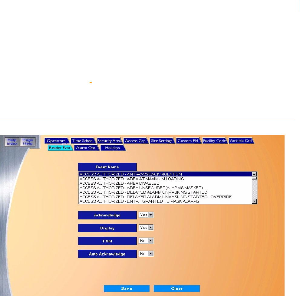
Chapter 8
Setup
187
Reader Event Page
The Reader Event page allows you to select how events related to access attempts are handled.
The selections determine the system's response to a denied or authorized access event. You can
determine whether to Acknowledge, Display, or Print each of the possible access attempts.
For a list of reader events, see Appendix A, Access Code Definitions.
To navigate to the Reader Event page, from any Setup page click the Reader Evnt. tab button at the
top of the window, or from the main Setup page click the Reader Event button on the right side of the
page. The following page displays.
Figure 136.Reader Event
The Reader Event page contains the following information:
Event Name A list of all denied or authorized access event defined in the system. For a complete listing, see
Appendix A, Access Code Definitions
Acknowledge Select Yes/No if the operator should or should not be required to acknowledge the event when it
occurs.
Display Select Yes/No if the workstation should or should not display the access event when it occurs.
Print Select Yes/No if the events printer should or should not print the access event when it occurs.
Auto Acknowledge If the Auto Acknowledge field is set to Yes, the reader event is displayed in the alarm queue window
and does not require any action by the operator. It clears after a period of time.
Note: The Auto Acknowledge field is not affected by the Acknowledge field.
Save Once all changes have been made to the Reader Event page, click Save.
After clicking Save, the “Operation Complete” messages displays.
Clear At any point if you wish to clear out all entered information and start over, click Clear.
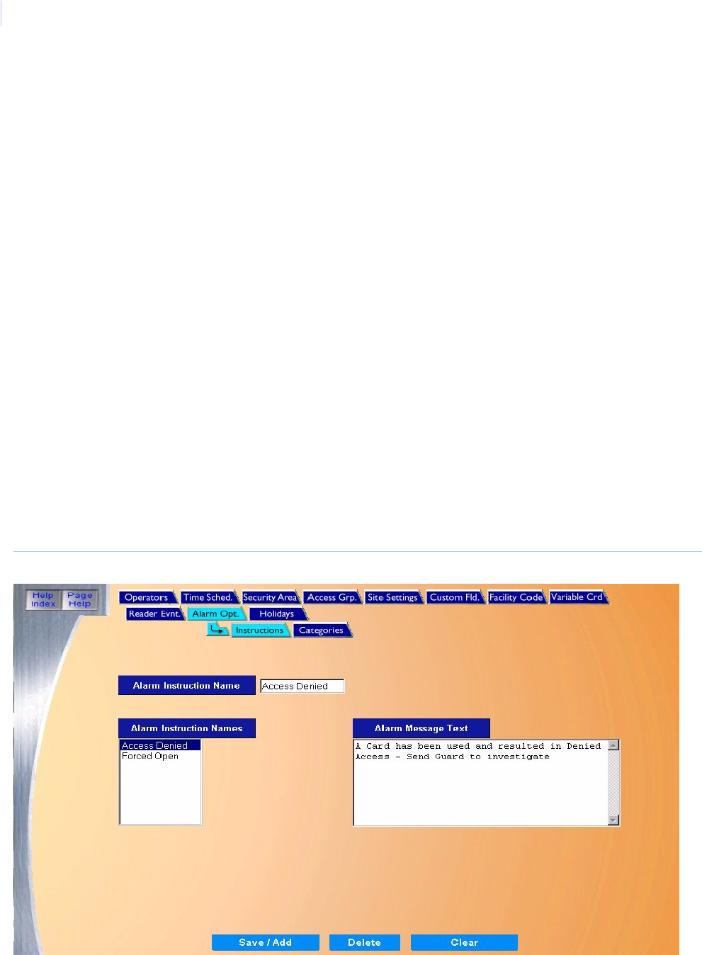
Topa z
User Manual
188
How to configure reader events
1. Select from the list of Event Names by scrolling through the list and clicking on the name of
the event to be configured.
2. Select Yes/No for the following settings:
• Acknowledge
• Display
•Print
• Auto Acknowledge
3. After all events have been set up, click Save. After clicking Save the message “Operation
Complete” displays.
Alarm Options
The Alarm Options setup has two sub-pages that allow you to add Alarm Instructions and define
alarm catagories.
Alarm Instruction Page on page 189
Alarm Categories Page on page 191
To navigate to the Alarm Options pages from any setup page, click the Alarm Opt. tab button at the
top of the window, or from the main Setup page click the Alarm Options button on the right side of
the page. The following page displays.
Figure 137.Alarm Options
The sub-pages are covered in detail on the following pages.
Alarm Instruction Page
The Alarm Instruction page allows you to add unique instruction messages to be displayed to the
operator when an event occurs.
To navigate to the Alarm Instruction page from any setup page, click the Alarm Opt. tab button at
the top of the window, or from the main Setup page click the Alarm Options button on the right side
of the page. Then click the Instructions tab button and the following page displays.
Figure 138.Alarm Options: Instructions
The Instructions page contains the following information:
Alarm Instruction Name Enter up to 16 alphanumeric characters for the Alarm Instruction Name.
Alarm Instruction Names A list of previously defined Alarm Instructions.
Alarm Message Text Enter up to 495 alphanumeric characters for Alarm Message Text.
Save/Add Once all changes have been made to the instruction message, click Save.
After clicking Save, the Operation Complete messages displays.
Delete Click to delete the selected Alarm Instruction from the database.
Clear At any point if you wish to Clear out all entered information and start over, click Clear.
CAUTION: Clicking Clear before clicking Save deletes newly entered data.
How to add an instruction message
1. Start by clicking Clear to clear all fields for data entry.
2. Enter the Alarm Instruction Name.
3. Enter the Alarm Message Text.
4. Click Save/Add to save the new instruction message.
A message “Operation Complete” displays.
How to modify an instruction message
1. Start by selecting the Alarm Instruction Message to be modified by clicking on the name listed
in the Alarm Instruction Names list.
2. After making changes to the Message text, click Save/Add.
A message “Operation Complete” displays.
How to delete an instruction message
1. Start by selecting the Alarm Instruction Message to be deleted by clicking on the name listed
in the Alarm Instruction Name list.
2. After making sure the correct message to be deleted is selected (highlighted), click Delete.
3. A message “Are you sure you want to delete this record?” displays. Click OK to continue.
A message “Operation Complete” displays.
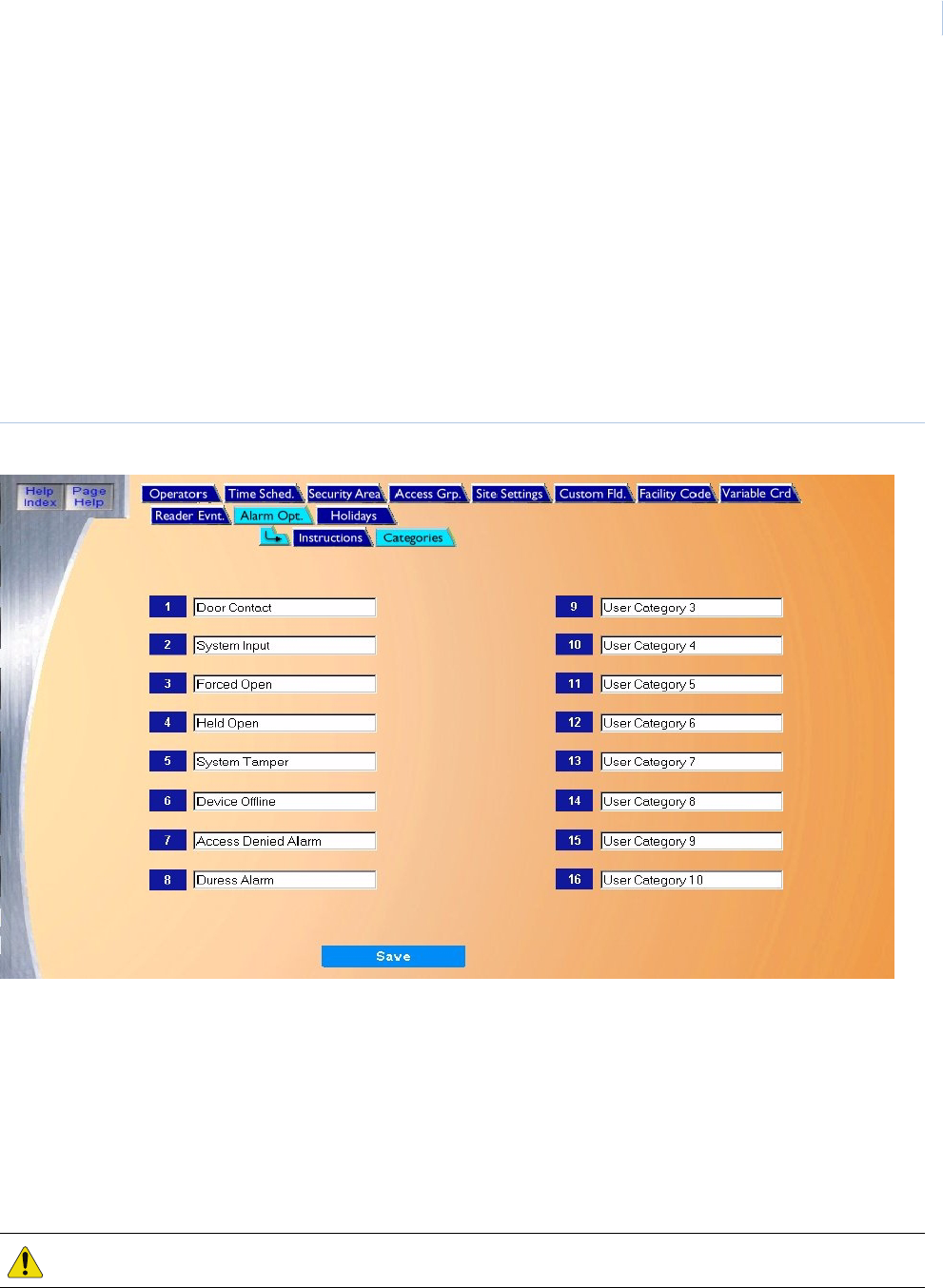
Chapter 8
Setup
191
Alarm Categories Page
The Alarm Categories page allows you to group alarm events by name. The System comes with 16
generic alarm categories. The alarm categories appear in event reports and classify alarm events.
You can change any alarm category designation (defaults are shown below) to a description that is
better suited to your facility or application.
It is helpful to group alarms points into categories like “Intrusion Alarm” or “Maintenance Alarm”, so
they can be recalled from history by that group, etc.
To navigate the Alarm Categories page from any setup page, click the Alarm Opt. tab button at the
top of the window, or from the main Setup page click the Alarm Options button on the right side of
the page. Then click the Categories tab button and the following page displays.
Figure 139.Alarm Options: Categories
The Categories page contains the following system default categories:
You can make any changes desired to the category names and click Save.
A message “Operation Complete” displays.
1 Door Contact 5 System Tamper 9 User Category 3 13 User Category 7
2 System Input 6 Device Offline 10 User Category 4 14 User Category 8
3 Forced Open 7 User Category 1 11 User Category 5 15 User Category 9
4 Held Open 8 User Category 2 12 User Category 6 16 User Category 10
CAUTION: Clicking Clear before clicking Save will delete all category names!
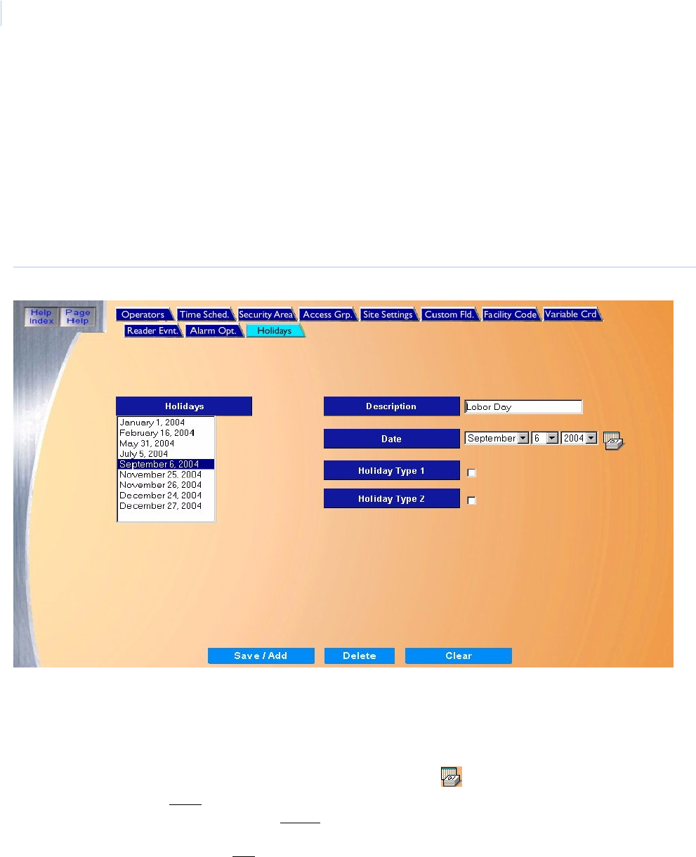
Topa z
User Manual
192
Holidays Page
The Holidays page allows you to predefine up to 32 Holidays to be used with Time Schedules to
authorize access, control alarms, and output relays. Holidays are normally used to make the date
assigned behave like another day off, for example, a Saturday or Sunday. If no Holiday is assigned
for a given date, then the normal access rules apply for that date.
To navigate the Holidays page, from any Setup page click the Holidays tab button at the top of the
window, or from the main Setup page click the Holidays button on the right side of the page. The
following page displays.
Figure 140.Holidays
The Holidays page contains the following information:
Holidays A list of all defined holidays.
Description Enter the name of the holiday, up to 27 alphanumeric characters
Date Select the Date for the holiday by clicking on the down arrow to the right of the fields and clicking on
the desired date. A calendar is available by clicking the Calendar.
Holiday Type 1/2 Select which types of Holiday are active for a given date.
• If a Holiday is defined without a Holiday Type, then the Holiday is like a regular day off, in other
words, normal access schedules apply.
• If it is defined with a Holiday Type, then access for that date acts according to the schedule set up
for that type. For more information on setting up holidays, see Time Schedule Page on page 166.
Save/Add Once all changes have been made to the Holidays page, click Save.
After clicking Save, the “Operation Complete” messages displays.
Delete Click to delete the selected holiday from the database.
Clear At any point if you wish to clear out all entered information and start over, click Clear.

Chapter 8
Setup
193
How to add a new holiday
1. Start by clicking Clear to clear all fields for data entry.
2. In the Description field enter the name of the holiday.
3. Select the Date for the holiday.
4. If access on this holiday is to follow a schedule other than the normal schedule, select a
holiday type.
Holiday Types are normally used for different countries where the date is treated
differently. For example, some countries may have the Friday after the U.S. Thanksgiving
as a day off, and access will be very limited. Other countries may treat it as a normal
Friday to allow an overtime crew to work. Holiday types can also be used to allow a guard
to get in a door through one reader for that day, but not through the other doors.
Another example is to set Holiday Type 1 for hourly employees and Holiday Type 2 for
salaried employees. Type 1 could have a holiday defined to deny access for hourly
employees, but Type 2 would allow salaried employees access to work on that holiday.
5. After adding data to the fields click Save/Add.
A message “Operation Complete” displays.
How to modify a holiday
1. Select the Holiday to be modified from the Holidays list by clicking on the name to highlight it.
2. After making all required modifications to the Holiday, click Save/Add.
A message “Operation Complete” displays.
How to delete a holiday
1. Select the Holiday to be deleted from the Holiday list by clicking on the name so it is
highlighted.
2. Click Delete.
3. A message “Are you sure you want to delete this record?” displays. Click OK to continue.
A message “Operation Complete” displays.

Topa z
User Manual
194

This chapter includes information on how to set up and configure hardware
connected to the Topaz system.
In this chapter:
Overview. . . . . . . . . . . . . . . . . . . . . . . . . . . . . . . . . . . . . . . . . . 196
Serial Port. . . . . . . . . . . . . . . . . . . . . . . . . . . . . . . . . . . . . . . . . 197
LAN Communication. . . . . . . . . . . . . . . . . . . . . . . . . . . . . . . . . 200
Workstation Page . . . . . . . . . . . . . . . . . . . . . . . . . . . . . . . . . . . 204
Field Panel Page . . . . . . . . . . . . . . . . . . . . . . . . . . . . . . . . . . . 222
Field Panel Setup Page . . . . . . . . . . . . . . . . . . . . . . . . . . . . . . 223
Dial-up Page. . . . . . . . . . . . . . . . . . . . . . . . . . . . . . . . . . . . . . . 226
Elevator Control . . . . . . . . . . . . . . . . . . . . . . . . . . . . . . . . . . . . 229
Elevator Cab Setup . . . . . . . . . . . . . . . . . . . . . . . . . . . . . . . . . 231
Elevator Floor Definition Page . . . . . . . . . . . . . . . . . . . . . . . . . 233
Elevator Public Access . . . . . . . . . . . . . . . . . . . . . . . . . . . . . . . 235
Readers . . . . . . . . . . . . . . . . . . . . . . . . . . . . . . . . . . . . . . . . . . 238
Reader Setup Page . . . . . . . . . . . . . . . . . . . . . . . . . . . . . . . . . 238
Reader Options Page . . . . . . . . . . . . . . . . . . . . . . . . . . . . . . . . 243
Alarm Point . . . . . . . . . . . . . . . . . . . . . . . . . . . . . . . . . . . . . . . . 245
Alarm Point Setup. . . . . . . . . . . . . . . . . . . . . . . . . . . . . . . . . . . 245
Alarm Point Options Page . . . . . . . . . . . . . . . . . . . . . . . . . . . . 248
Relay Page . . . . . . . . . . . . . . . . . . . . . . . . . . . . . . . . . . . . . . . . 250
Auto Configuration Setup Page . . . . . . . . . . . . . . . . . . . . . . . . 252
Device Tree. . . . . . . . . . . . . . . . . . . . . . . . . . . . . . . . . . . . . . . . 257
Video Recorder. . . . . . . . . . . . . . . . . . . . . . . . . . . . . . . . . . . . . 258
Video Camera. . . . . . . . . . . . . . . . . . . . . . . . . . . . . . . . . . . . . . 261
Chapter 9 Hardware
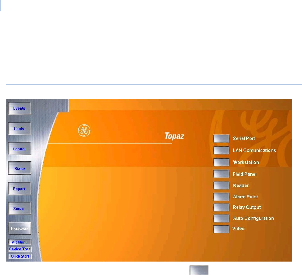
Topa z
User Manual
196
Overview
The Hardware pages allow you to setup and configure hardware connected to the System.
To navigate to the Hardware pages, click the Hardware button in the Main navigation button window
on the left side of the screen. The following page displays.
Figure 141.Hardware
To access one of the options in the Hardware pages, click the button next to the option.
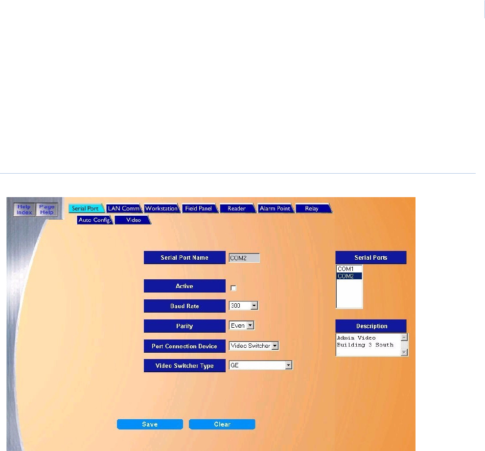
Chapter 9
Hardware
197
Serial Port
The Serial Port page is used to setup or modify settings of the PC Workstation's serial
communication ports. Configuration includes if the port is active or not, communication baud rate
(speed), etc.
To navigate to the Serial Port page from any Hardware page, click the Serial Port tab button at the
top of the window, or from the main Hardware page click the Serial Port button on the right side of
the page. The following page displays.
Figure 142.Serial Port
The Serial Port page contains the following information:
Serial Ports From the list select the serial port to configure or modify by clicking on the port in the
Serial Ports window at the top right side of the page. Topaz supports up to five serial ports.
Serial Port Name This field is display-only to show the name of the currently selected port.
Active If the port is going to be used to actively communicate to field hardware it must be
selected by clicking the box to the right to place a check mark in the box.
Baud Rate From the drop-down list select the baud rate that the equipment connected to the serial
port communicates at. The possible selections are: 300, 600, 1200, 2400, 9600, and
19200.
Parity From the drop-down list select the parity for the equipment that is connected to the serial
port. The possible selections are: Even, None, and Odd.
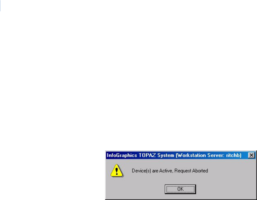
Topa z
User Manual
198
Port Connection Device From the drop-down list select the type of device that connected to the port. The list of
equipment selection is as follows
• SCP Device
• SCP Dial-up
• Video Switcher - If this device is selected, the Video Switcher Type field is active
allowing a selection of a brand of switcher.
Note: You cannot change the connection device after the serial port has been saved.
You cannot change the connection device after the field panel is assigned to a
serial port.
If you wish to change the port connection device you must deactivate the port by un-
checking the Active box and clicking Save. Then you may modify the port. This feature is
only available in Topaz Ver-1.30 and later. If the following message displays, you must
first deactivate all field panels that are configured on the port before you can deactivate
the port.
Video Switcher Type Before this field becomes active Video Switcher must be selected for the Port Connection
Device. Select the brand of video switcher from the drop-down list. The list of possible
switchers is given below:
• American Dynamics
•Burle
•GE
• Kalatel
• Panasonic
•Pelco
• Quest Plus
• Quest Win
•Vicon
See Video Switcher Commands on page 199 for examples of commands that are sent to
the switcher.
Description Enter up to 60 alphanumeric characters to describe the device(s) connected to this port.
Clear Clicking Clear at anytime clears changes that have been entered.
Save After all changes have been made to the Serial Port page, click Save.
One of the following messages displays.
• If “Operation Complete” is displayed, then no further changes are needed.
• If “Operation Failed” is displayed, then a required field was not entered. Enter the
field and try again.

Chapter 9
Hardware
199
Video Switcher Commands
Table 16. Samples of outgoing commands from the ACU
Sent to: Format Description Command
American Dynamics
Video switcher
ASCII Alarm 001Ea<cr> Contact 001
Cancel 001Ia<cr> Contact 001
Vicon
Video switcher
ASCII Alarm <01h>u0001S<cr> Contact 001
Cancel <01h>u0001R<cr> Contact 001
Javelin
Win Quest switcher
HEX Alarm “FF” “06” “86” “04” “00” “01” “02” “92” Contact 001
Cancel “FF” “06” “86” “04” “00” “01” “03” “93” Contact 001
Javelin
Quest Plus switcher
ASCII Alarm 0001Ea Contact 001
Cancel 0001Ia Contact 001
Kalatel
Video switcher
ASCII Put camera 001 in alarm 00[001~
Reset camera 001 from alarm 00\001~
Phillips/Burle
Video switcher
ASCII Alarm +ALARM 1<cr> Contact 001
Cancel -ALARM 1<cr> Contact 001
Phillips/Burle
Var Speed
Video switcher
ASCII Alarm +ALARM 1<cr> Contact 001
Cancel -ALARM 1<cr> Contact 001
Pelco
Video switcher
ASCII Alarm 001Ia Contact 001
Cancel 001Ea Contact 001
Panasonic
Video switcher
HEXI Alarm “02 43 4d 44 3a 48 41 28 38 30 30 30 30 30 30 30 30
30 30 30 30 30 30 30 29 03” Contact 001
Cancel “02 43 4d 44 3a 48 41 28 30 30 30 30 30 30 30 30 30
30 30 30 30 30 30 30 29 03” Contact 001
Elbex
CCTV switcher
ASCII Alarm
Cancel
Pelco CM6800
CCTV switcher
ASCII Alarm 1 active
Alarm 128 active
1Je
128Je
Alarm 1 secure
Alarm 128 secure
1~Je
128~Je
Ultrak
CCTV switcher
ASCII Alarm 1 active
Alarm 128 active
#0[A1=T]<cr>
#0[A128=T]<cr>
Alarm 1 secure
Alarm 128 secure
#0[A1=F]<cr>
#0[A128=F]<cr>
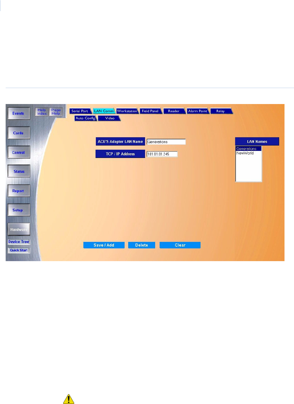
Topa z
User Manual
200
LAN Communication
The LAN Communication page allows you to configure the LAN Adapters and TCP/IP address.
To navigate to the LAN Communication page from any Hardware page click the LAN Com tab button
in the top navigation bar, or from the main Hardware screen click the LAN Communications button
on the right side of the screen. The following page displays.
Figure 143.LAN Communication
The LAN Communication page contains the following information:
ACU’s Adapter LAN Name Enter a name up to 31 characters
TCP/IP Address Enter the TCP / IP Address for the LAN adapter.
Note: If you are not sure what the TCP / IP address is, you should contact your LAN
Controller. Do not guess or enter a random number
LAN Names A list of previously defined ACU Adapter LAN Names
Save/Add After all changes have been made, click Save.
One of the following messages displays.
• If “Operation Complete” is displayed, then no further changes are needed.
• If “Duplicate Record” is displayed, then the LAN Adapter Name has been repeated.
Use a new name and try again.
• If “Operation Failed” is displayed, then a required field was not entered. Enter the
field and try again.
Delete Click to delete the selected LAN adapter.
CAUTION: Before deleting a LAN adapter, make sure that no field panels are assigned to
the LAN adapter you are deleting.
Clear Clicking Clear at anytime clears changes that have been entered.

Chapter 9
Hardware
201
How to add a new LAN adapter
1. Start by clicking Clear to clear all fields.
2. Enter the LAN Adapter Name.
3. Enter the TCP / IP Address for the LAN adapter.
4. After all fields have been added to the LAN Communication page, click Save/Add. A
message “Operation Complete” displays.
How to modify a LAN adapter
1. Select the LAN Adapter to be modified from the LAN Adapters list by clicking on the name to
highlight it.
2. After making all required modifications to the LAN Adapter Name and/or TCP/IP Address,
click Save/Add. If you change the name, the old LAN Adapter is deleted.
A message “Operation Complete” displays.
How to delete a LAN adapter
1. To delete a LAN Adapter from the System you must first select the LAN Adapter to be
deleted. Do this by clicking on the name of the LAN Adapter in the Configured LAN Adapters
list.
2. After making sure the correct LAN Adapter to be deleted has been selected click Delete.
3. A message “Are you sure you want to delete this record?” displays. Click OK to continue.
The message “Operation Complete” displays.
CAUTION: Before deleting a LAN adapter, make sure that no field panels are assigned to the LAN adapter you are
deleting.

Topa z
User Manual
202
Network Communications
This section provides guidelines for the network environment needed to support communication
between a Topaz Server and ACU Networked Intelligent Controller Field Panels. While it is not possible to
address every variable that may exist in a customer’s network environment, this highlights key network
considerations.
The information in the following table is assuming a minimum Topaz server software revision of 1.47
and a minimum ACURT panel firmware revision of 7.13.00
Table 17. Network communications guidelines
Port The TCP/IP port number that the ACU panel listens to is 3000 plus the system WAN number (typically
3001).
Protocol TCP/UDP
All messages are less than 255 bytes. The protocol is a simple command and response protocol with a
sequence number retry mechanism.
Timing Polling
Frequency
400 milliseconds per ACU panel (fixed)
Server Wait
and Delay
Time
Wait time for the server to receive a response is 500 milliseconds. Networks should be
able to respond to a ping for each panel within 500 milliseconds for optimum
performance.
Additional user-configurable delay time of up to 3000 milliseconds can be set for each
panel. Typical additional delay is 500 milliseconds.
Server Retry If the server does not receive a response from the panel within the delay time described
above, the server re-sends another poll to the panel. The default number of retries is 3.
The Retry for each panel can be increased up to 10 by the system administrator. Setting
the number of retries above three is usually for testing purposes only, and not intended
for normal operation of the system.
Panel
Timeout
If a panel does not receive a correct message from the server within 10 seconds, the
panel no longer responds to the server (a “local panel off-line” condition). This could be
caused by a network interruption or incorrect message(s). An example of an incorrect
message might be if the network corrupts a server message, resulting in a checksum
error. This causes the server to resynchronize communications with the panel. A
corresponding message is reported at the server as a “panel off-line”.
Timing
Calculations
To determine proper panel settings for optimal communication, perform the following
calculations for each panel. The total delay, including retries, should be less than 10
seconds (Panel Timeout); The lower the total, the more optimal system performance.
ACU LAN Panel with no downline panels via serial connection:
#Retries X [Delay Time(secs) + Wait Time(secs)] = Total
For example: 3 X [1.2 + 0.5] = 5.1
ACU LAN Panel hosting down-line panels via serial connection:
#Down-line panels X #Retries X [Delay Time(secs) + Wait Time(secs)] = (Total)
For example: 3 x 3 x [0.5 + 0.5] = 9
Bandwidth
Dynamics
It is important that allocated bandwidth remains consistent at all times and is not clamped down (or
reduced) during off-hours such as at night or on weekends. Inconsistent or dynamic bandwidth can
result in inconsistent on-line/off-line behavior of field panels, especially if network throughput is
marginal.

Chapter 9
Hardware
203
Network Hops To ensure consistency, the number and distance of hops between a field panel’s LAN port and it’s
hosting server should be kept to a minimum.
Download
Activity
Two types of download activity can occur: Full panel downloads or smaller downloads that occur
during routine use of the system. During the download operation, the ACU is fully operational after
power-up. Access requests are processed and normally, little delay is experienced. However, large
amounts of activity have an adverse effect on system performance.
A full panel download can be initiated manually by the system administrator, or automatically when:
• A panel is powered-up or reset
• A change is made to Access Groups
• A panel definition is modified
• A new reader is defined
• An elevator floor definition is modified.
Note: During a full panel download, the entire card database is downloaded to the panels, however
only those cards which are authorized for access through doors controlled by a panel are
downloaded to that panel, thus reducing per-panel traffic.
Following a server restart, all alarm points, relays, time schedules, and other user-programmed
settings and parameters are downloaded. The card database is only downloaded if, after a
comparison, the server detects that cardholder changes were made at the server but not updated to
the ACU.
If an initial download from the server to the ACU is interrupted, the ACU waits for the download to
restart.
Note: ACU2X: After a successful download, the ACU2X saves the count of cards in its database. If
a subsequent full card download is interrupted, the panel restores the original pointers so that
a backup mechanism exists until a successful download is achieved.
ACU
Comparison
The ACU2XL, ACURS, and ACURT panels are approximately 100 times faster for communication that
an ACU2 or ACU2X panel with the LanTronix kit. This is because a panel using the LanTronix kit
connects to the kit from the panel serial port that runs at an average of 9600 baud, whereas the
ACU@XL, ACURS, and ACURT panels run at the 10 Mbps rate of their built in network card.
Table 17. Network communications guidelines (continued)
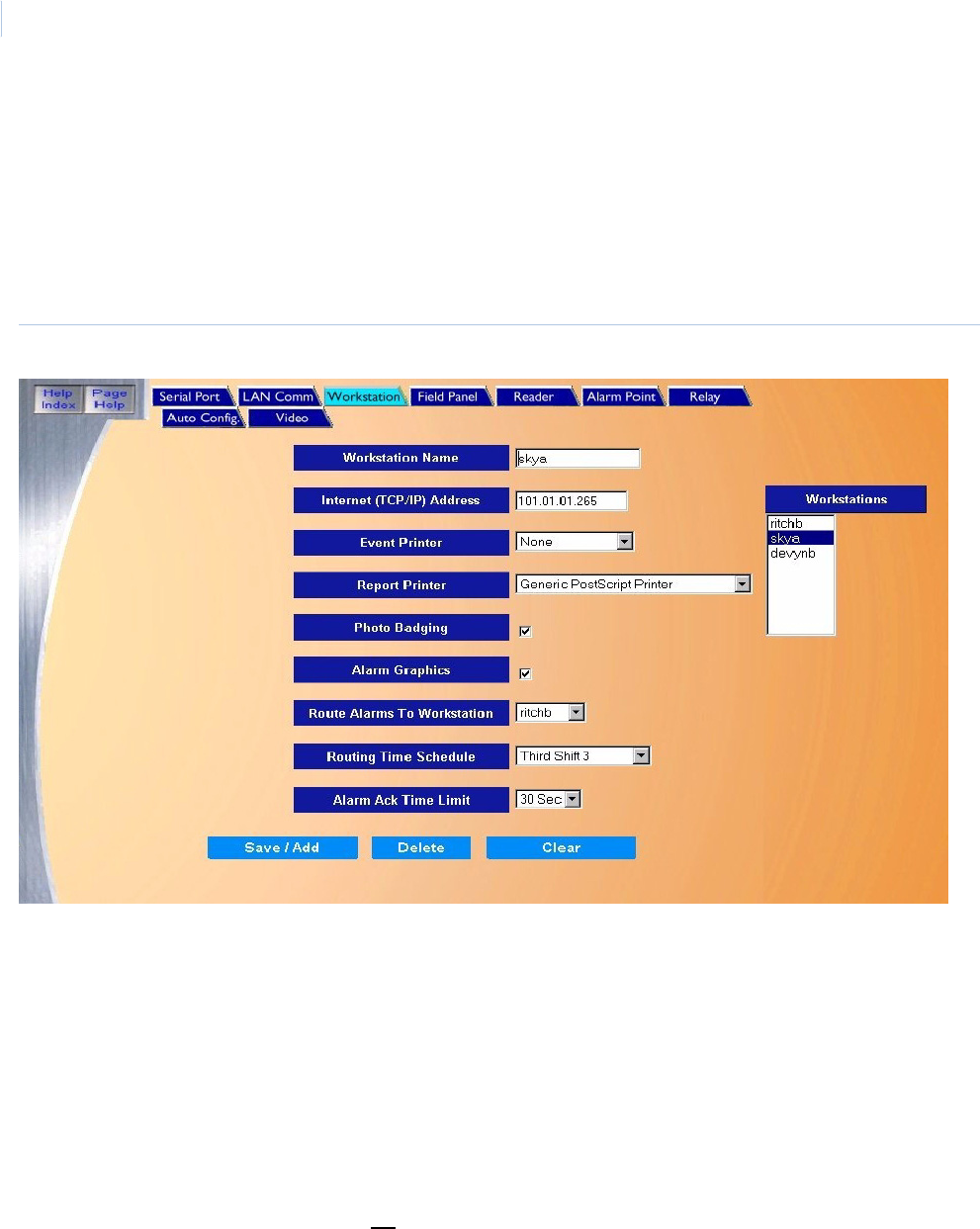
Topa z
User Manual
204
Workstation Page
The Workstation page allows you to control how the workstation responds during use. For example,
whether the workstation has photo badging capability, alarm color graphics capability, etc.
To navigate to the Workstation page, click the Workstation tab button in the top navigation bar or
from the main Hardware screen click the Workstation button on the right side of the screen. The
following page displays.
Figure 144.Workstation.
The Workstation page contains the following information:.
Workstation Name The Workstation Name is used to identify a workstation and may have up to 32 characters.
You may have only one (1) workstation on the system and it must have a unique name to
identify it from the server workstation.
Note: It is not recommended that you modify the Workstation Name.
Internet (TCP/IP) Address The server must know the Internet (TCP/IP) Address of the workstation to allow the
workstation to log-on. This TCP/IP address is setup automatically the first time the
Workstation runs the Topaz software. If you are not sure about the TCP/IP address, contact
your Network Administrator.
Note: It is not recommended that you modify the Internet TCP/IP Address.

Chapter 9
Hardware
205
Event Printer To select an event printer, click the drop-down list and click the name of the local printer.
The Event Printer prints all events that are generated by the system. The default is “None”.
Note: If no printer is listed, you need to configure a local printer connected directly to the
workstation.
CAUTION: You cannot select the same printer for both Event Printer and Report Printer.
You must use two different printers. After you configure the local printer properties you
can select the Event Printer under Hardware – Workstation.
For more information, see How to configure an event printer on page 218.
Report Printer If you want to print reports, a Report Printer must be selected. The drop-down list shows all
configured printers listed that have been added to the workstation. The default is “None.”
Select a printer by clicking on it.
If there are no printers listed to choose from, you need to set the properties of a printer
available to this workstation. It can be either a local printer connected directly to the
workstation, or a network printer. You cannot select the same printer for both Event Printer
and Report Printer. You must use two different printers.
For more information, see How to configure a report printer on page 220.
Photo Badging If you want to use Photo Badging at this workstation, click the box to place a check mark in
it.
Alarm Graphics If you want to use Alarm Color Graphics at this workstation, click the box to place a check
mark in it.
Route Alarms to Workstation Alarms assigned to this workstation can be temporarily rerouted to another workstation
during certain times of the day and days of the week. To select a workstation to temporarily
route this workstation’s alarms to, select that workstation from the drop-down list.
This routing can also be used to manually reroute alarms at anytime by selecting the
workstation you wish to route the alarms to and then set the time schedule to route to the
default of “Always” in the next field.
Routing Time Schedule If you have selected a workstation in the above field to route alarms, you must also select
the time schedule for the routing to start and end. Select from the drop-down list any pre-
configured Time Schedule during which you wish to reroute alarms.
Alarm Ack Time Limit You may select from the drop-down list the time limit allowed for the alarm to be
acknowledged. The default is None (will not expire) and the options are 5, 10, 15, 20, 25,
30, 45 seconds, and 1, 1.5, and 2 Minutes. After the timer expires at the Alarm Workstation,
then the No ACK Workstation signed in the Alarm Point Setup receives the alarm for
acknowledgement
Save/Add After all changes have been made to the Workstation page, click Save/Add.
One of the following messages displays.
• If “Operation Complete” is displayed, then no further changes are needed.
• If “Duplicate Record” is displayed, then the Name entered for the workstation has been
repeated. Use a new name and try saving again.
• If “Operation Failed” is displayed, then a required field was not entered. Enter the field
and try saving again.
Clear At any point if you wish to clear out all entered information, click Clear.
CAUTION: Clicking Clear before clicking Save deletes newly entered data.

Topa z
User Manual
206
How to add a workstation
To add a workstation, you should first install the Topaz software on the new workstation’s computer.
When that workstation logs on with the software for the first time, the server creates a new record for
that workstation under the Workstation Name field and the Internet (TCP/IP) Address. The values
for all fields on the workstation screen are the default values. See How to install a workstation on
page 207.
If you add a new workstation from the server, it does not become effective until the Topaz software is
installed on that workstation and the software is started from that workstation. We recommend that
you first install the software on the workstation, and then make any changes you want to the
workstation screen for added functionality, for example, the use of Photo Badging.
How to modify a workstation
After the software is installed on a workstation and you run the Topaz software (which connects the
workstation to the server), you can make changes to any workstation, including the one being used.
This means you can set the functionality for a workstation from that workstation, as long as you have
the proper user permission level.
1. You can select the information for any workstation by selecting its name from the right side of
the screen under Workstation. This displays on the screen the information for that
workstation.
2. Make the necessary changes.
3. Click Save. The message “Operation Complete” displays.
How to delete a workstation
To permanently delete a workstation from the system, you must:
1. Delete the Topaz software from the workstation computer.
2. On the server, under Hardware, Workstation, select that workstation by name.
3. Click Delete.
4. A message “Are you sure you want to delete this record?” displays. Click OK to continue.
The workstation name is deleted from the list and the message “Operation Complete”
displays.

Chapter 9
Hardware
207
How to install a workstation
Setting up Internet Explorer:
1. From Window’s desktop, right-click the Internet Explorer Icon and select Properties.
2. On the General tab, click Settings, select Every visit to the page, and lastly click OK to save.
3. On the Security tab, click the Local Intranet icon. Click Custom Level. Under ActiveX
controls and plug-ins change Download signed ActiveX controls, Download unsigned
ActiveX controls and Initialize and script ActiveX controls not marked as Safe to Enable.
Then click OK to save.
4. On the Privacy tab, move the slide bar all the way down to Accept All Cookies then click OK
to save.
5. Click OK to save and exit Internet Explorer Properties.
Installing Topaz
Make sure the workstation Sentinel is plugged into the parallel port of the PC you are going to install
the workstation software on.
Make sure you are logged in as the Administrator so you have the correct rights to install software.
Insert the Topaz Installation CD into the CD drive. If Auto Insert Notification is enabled for your CD
drive, the Install Menu appears as shown below and provides a selection list.
If the Install Menu, as shown below, does not appear within one minute, follow this procedure:
1. Open Windows Explorer.
2. Double-click the drive of the CD.
3. In the root directory, double-click the file “start.bat”.
The Topaz Install screen displays.
Note: Before installing the Topaz Workstation, make sure that Topaz server has been installed and that the computers
are communicating. If you have Internet Explorer 6.0 already installed on your computer, check if the title bar
states “Microsoft Internet Explorer provided by GE”. If not, you must install the Virtual Machine that is located on
the CD. For more information see Installing Virtual Machine on page 8.
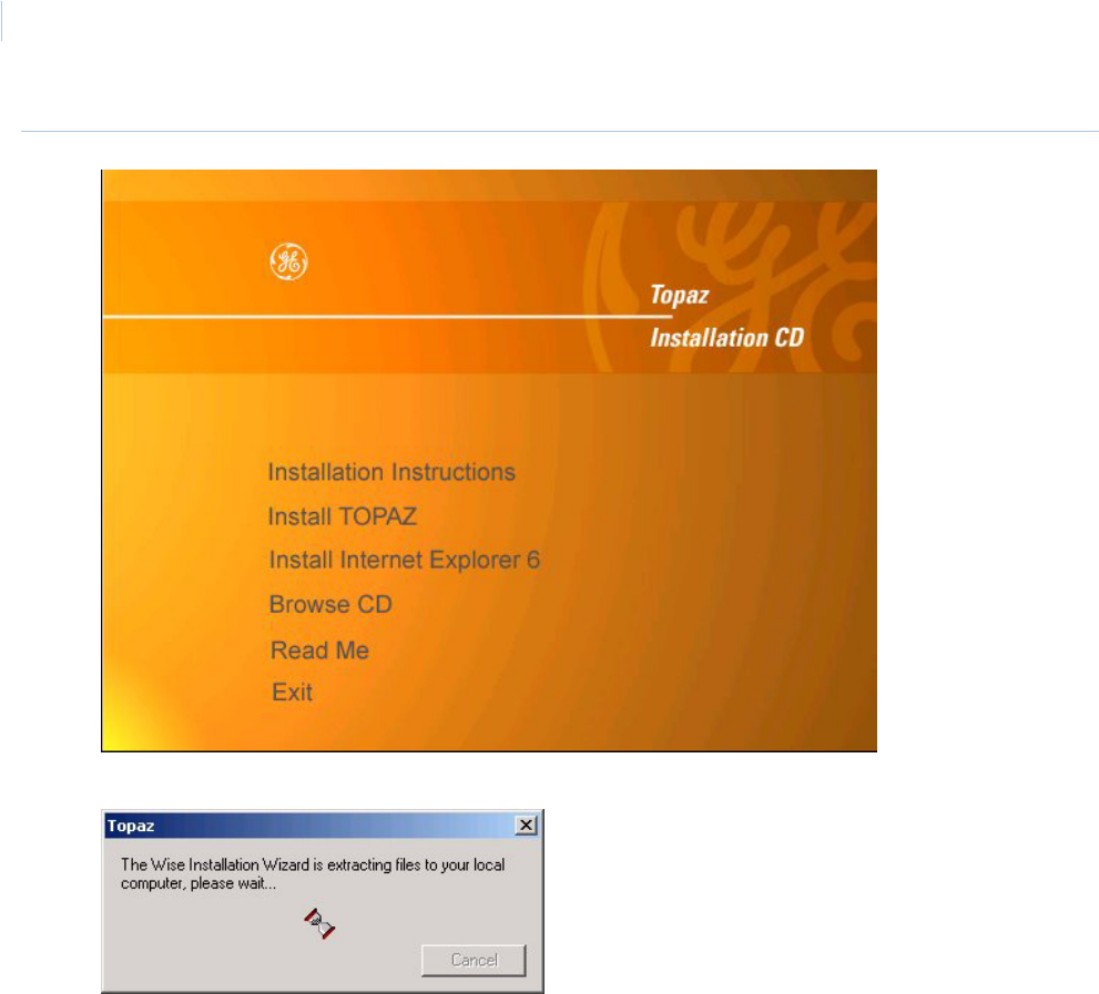
Topa z
User Manual
208
Figure 145.Topaz: Install
1. Click Install TOPAZ to start the installation setup.
2. If this is the first time Topaz has been installed on your computer and the Microsoft .NET
Framework is not installed, the Wise Installation Wizard dialog window shown above
displays. Extracting and installing the .NET framework may take several minutes. Please wait
while the Hourglass progress icon rotates. When the framework is completed, the Topaz
Installation Wizard begins. If the .NET framework is already installed on your machine, it
proceeds directly to the Welcome to the Topaz Installation Wizard dialog window.
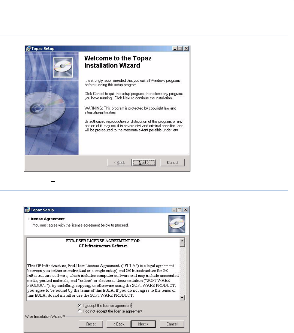
Chapter 9
Hardware
209
Figure 146.Topaz: Welcome
3. Click Next> to continue.
Figure 147.Topaz: License Agreement
The next window is the End User License Agreement. Read it then select I accept the
license agreement. The Next button becomes available once the agreement is accepted.
Click Next to continue.
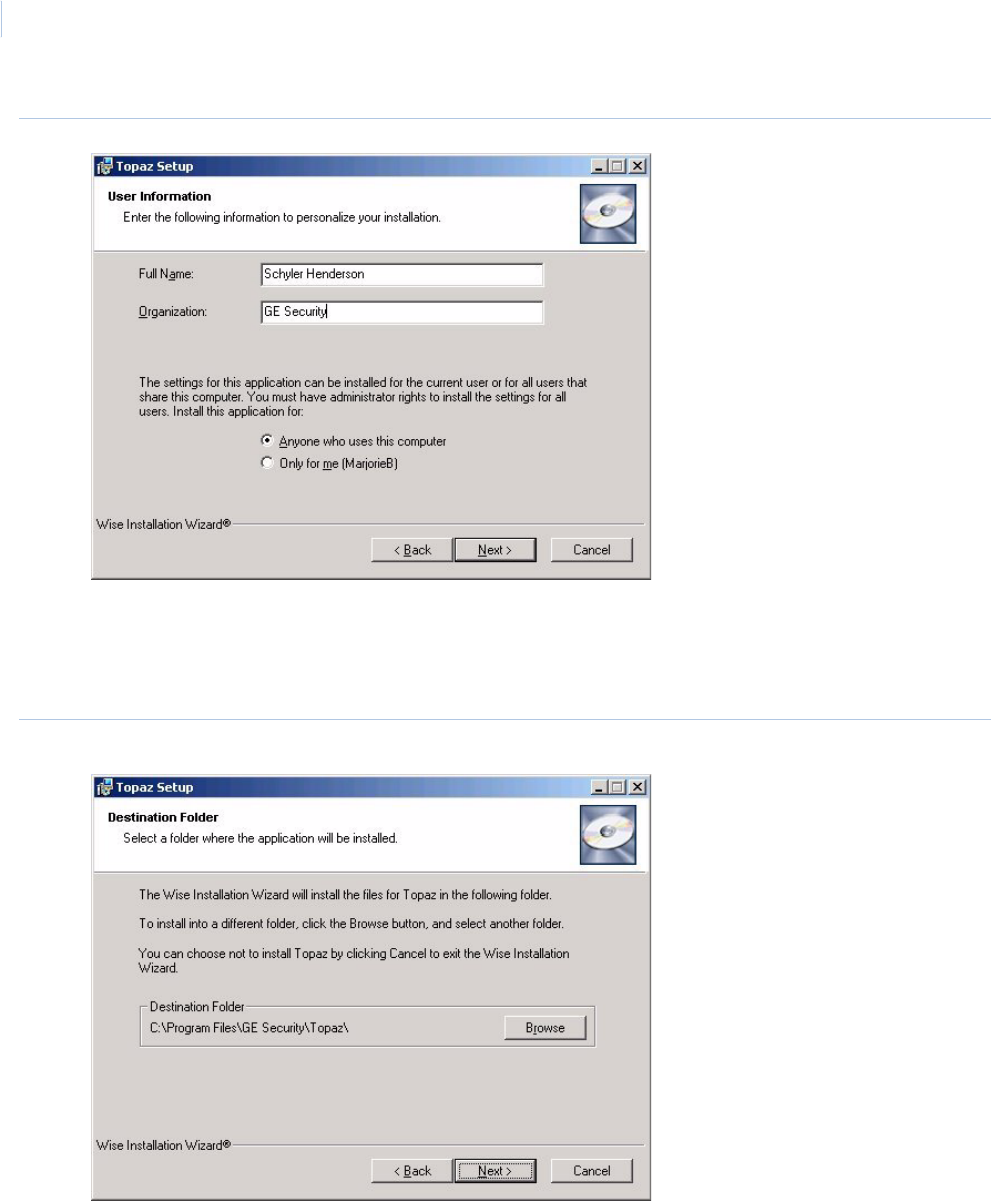
Topa z
User Manual
210
Figure 148.Topaz: User Information
4. The next window asks you to enter User Information. Type the name of the user in to the
Full Name field and the name of the organization into the Organization field. Select the radio
button beside Anyone who uses this computer. This is used to permit the system to
communicate with and respond to the Video Recorder. Click Next to continue.
Figure 149.Topaz: Destination Folder
This dialog window determines were the Topaz files is stored on the system. If you do not
want to use the default directory, you may follow this procedure:
a. Click Browse and the Browse for Folder window displays.
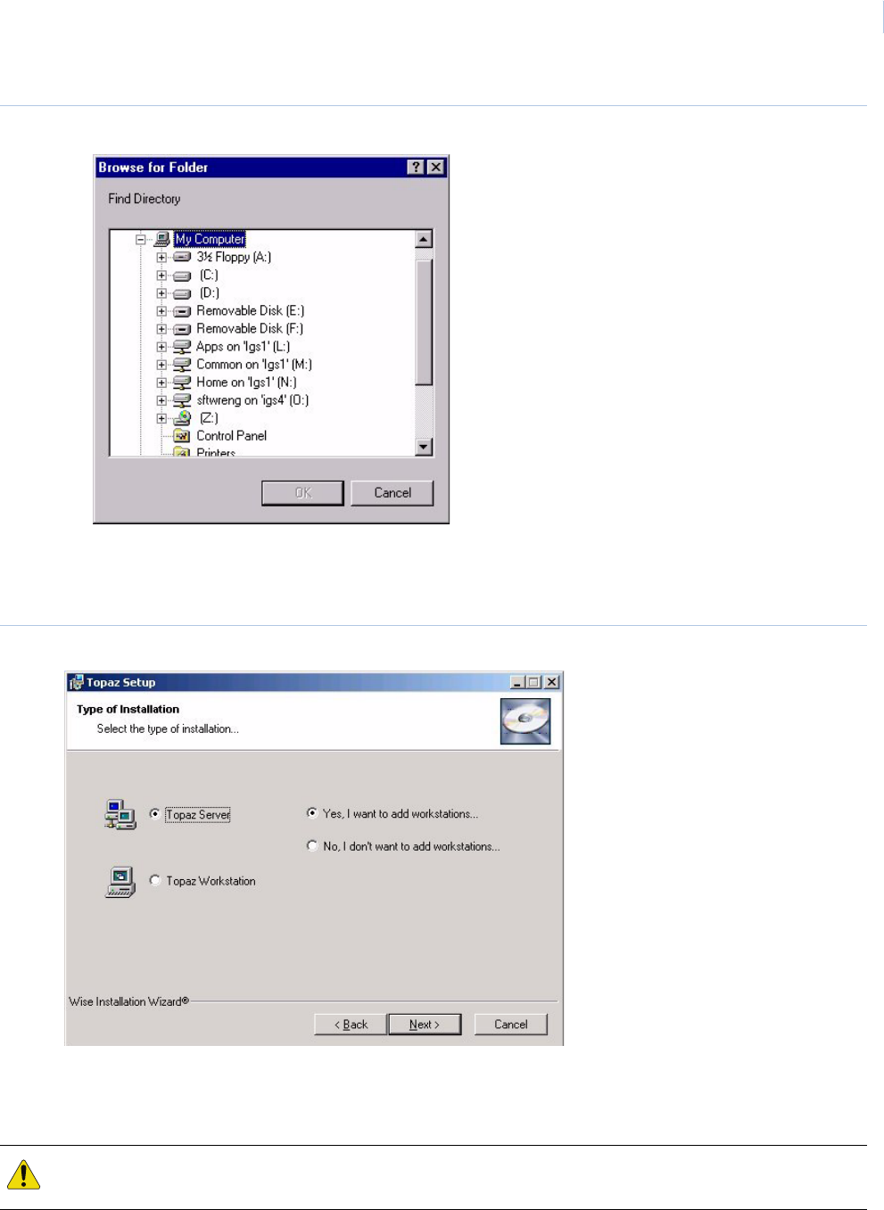
Chapter 9
Hardware
211
Figure 150.Browse for Folder
b. If you prefer to use a different directory, such as “Program Files”, select the desired
location for the Topaz software (such as C:\PROGRAM Files\Topaz) and click OK, then
Next.
Figure 151.Topaz: Type of Installation
5. This dialog window determines the type of installation you are doing. Since you are installing
the workstation, click the radio button next to Topaz Workstation. For information about
installing a server see Installing a Host PC Server on page 13.
CAUTION: You must install Topaz on the server computer before installing it on any workstation computer. Also
make certain that the server computer and the workstation computer are communicating properly.
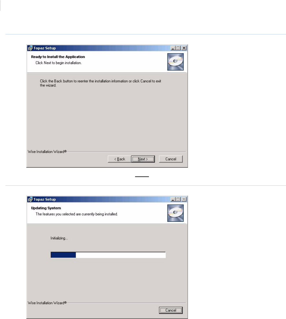
Topa z
User Manual
212
Figure 152.Topaz: Ready to Install the Application
6. If you satisfied with your settings, click Next to start installing the system.
Figure 153.Topaz: Updating System
The wizard uploads the required files and installs them onto the computer. During the
process, a progress bar displays.
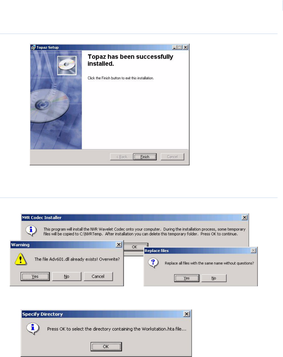
Chapter 9
Hardware
213
Figure 154.Topaz: Successfully installed
7. When all files have been installed, the Topaz has been successfully installed dialog
window displays. Click Finish to continue with the installation of several video files. These
files are installed whether or not you are using Video.
Figure 155.NVR Codec Installer
8. Click OK to install the Video files.
Note: If a warning window displays that certain files already exist, click Yes to continue. When the dialog window asks
whether to replace all files with the same name without questions, click Yes.
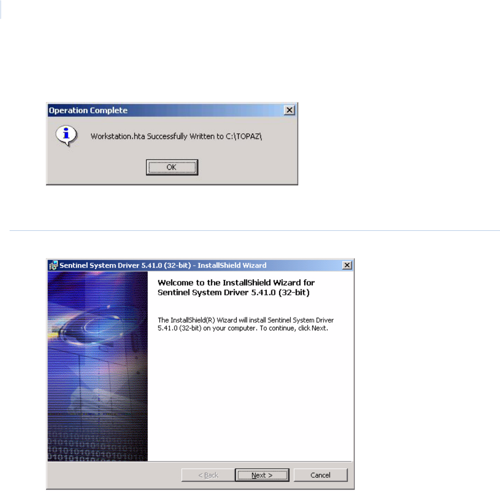
Topa z
User Manual
214
9. This dialog window appears if you selected Yes, I want to add workstations when installing
the server. Click OK and another Browse window appears. Select the directory or drive
where the Workstation.hta file was saved. After selecting the location click OK.
10. The dialog window indicates that the file was written successfully. Now wait a few seconds
and the Sentinel Driver installation wizard starts.
Figure 156.Sentinel System Driver: Welcome.
Note: If this is the first time you have installed Topaz on this computer, you should follow the remaining steps. If this is an
update, you may cancel out of the Sentinel Driver wizard.
11. Click Next > to install the sentinel drivers.
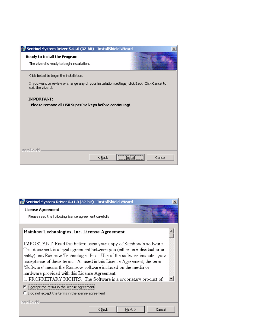
Chapter 9
Hardware
215
Figure 157.Sentinel System Driver: Ready to Install
12. Remove all software sentinel keys from the USB port before continuing. Click Install to
continue.
Figure 158.Sentinel System Driver: License Agreement
13. Select I accept the terms in the license agreement, and the Next button becomes
available. Click Next to continue.
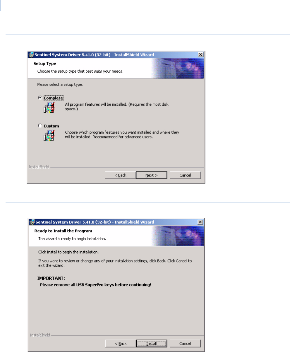
Topa z
User Manual
216
Figure 159.Sentinel System Driver: Setup Type
14. Select Complete, then Click Next > to continue.
Figure 160.Sentinel System Driver: Ready to Install
15. Remove USB sentinel keys before continuing, then Click Install. A screen with a progress
bar displays while the Sentinel Driver files are installed.
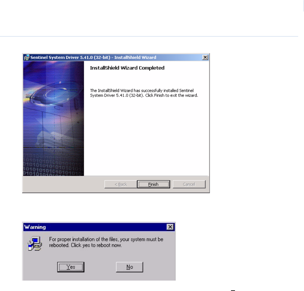
Chapter 9
Hardware
217
Figure 161.Sentinel System Driver: InstallShield Wizard Completed
16. Click Finish.
17. You are now returned to the desktop and the following message displays.
18. You must restart your PC for the Topaz software to be activated. Click Yes to reboot your
system.
This ends the installation steps for a workstation.
To start Topaz, double-click the Topaz icon on your desktop.
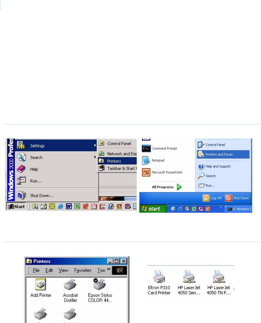
Topa z
User Manual
218
How to configure an event printer
To select an event printer, click the drop-down list and click the name of the local printer. The Event
Printer prints all events that are generated by the system. The default is “None”.
If no printer is listed, you need to configure a local printer connected directly to the workstation.
You cannot select the same printer for both Event Printer and Report Printer. You must use two
different printers. After you configure the local printer properties you can select the Event Printer
under Hardware – Workstation.
Set the properties for the local printer available to this workstation.
Do the following to configure the properties for the event printer.
1. Click Start, select Settings, and then Printers.
Figure 162.Start menu: Printers
2. Click Printers.
Figure 163.Printers window
3. Right click the printer icon that is directly connected to your workstation and click Properties.
Windows 2000 Windows XP
Windows 2000 Windows XP
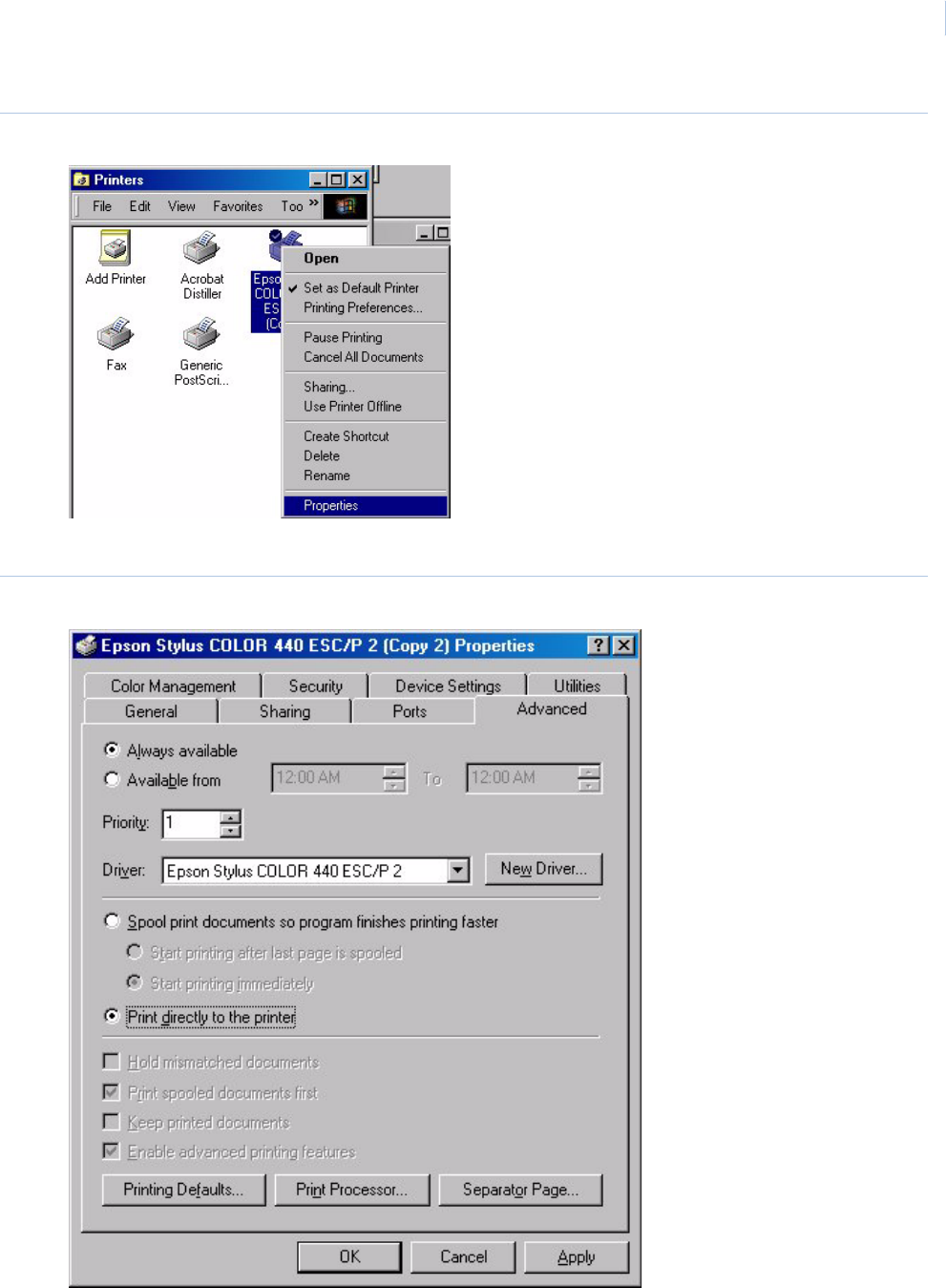
Chapter 9
Hardware
219
Figure 164.Printers menu
4. For windows 2000 click the Advanced tab.
Figure 165.Printer Properties window

Topa z
User Manual
220
5. Click the radio button to the left of Print directly to the printer to select it.
6. Click OK.
7. Close the Printers window.
Setup is now complete and you can now select the events printer in the Event Printer field on the
Workstation Page.
How to configure a report printer
If you want to print reports, a Report Printer must be selected. The drop-down list shows all
configured printers listed that have been added to the workstation. The default is “None”. Select a
printer by clicking on it.
If there are no printers listed to choose from, you need to set the properties of a printer available to
this workstation. It can be either a local printer connected directly to the workstation, or a network
printer. You cannot select the same printer for both Event Printer and Report Printer. You must use
two different printers.
If you want to set a printer to spool reports:
1. Click the Windows Start button.
2. Click Settings.
3. Click Printers.
4. Click Add Printer and select the printer for reports.
5. Click the Scheduling tab.
6. Under “Spool print documents so program finishes printing faster”, select Start printing after
last page is spooled. The Reports printer must wait to print until the entire report is sent to
the printer.
Now you can select the Report Printer under Hardware – Workstation.
Port usage
The table below details the various ports used by the Topaz workstation software. To check the ports
currently being used, from the command prompt, type the DOS command: netstat -a
Table 18. Port usage
Port # Name Recv Size Xmit Size Defining pgms
80 HTTP_PORT guihttp.h, guihtdvr.h, ie, setup.c
2000 IDS_ACU_DEF_PORT setupmp\instwizrc
3001 UDP_PORT tcpip.c
4900 LOG_PORT mpdbase.h (mp & mpuprun)
4950 WIZARD_PORT nt\MPWIZ.h
4955 PECOS_PORT nt\diamdmsg.h
5000 ONE32_PORT tcpip.c

Chapter 9
Hardware
221
5070 CGBDG_PORT 1024000 1024000 guihttp.h,
5080 EVENT_PORT 256 1024 guihttp.h, eventmsg.java
5090 DFRAME_PORT 1024 1024 guihttp.h, dframe.java
5200 nvrapi.cpp
5300 nvrapi.cpp, ncrctrl.js
6000 nvrapi.cpp
6080 ALARM_PORT guihttp.h, alarmmsg.java
6081 ALMREC_PORT 8192 4096 guihttp.h, alarmsend.java
7070 MONITOR_PORT 8192 512 guihttp.h, mpuprun.c
7077 NVRMONITOR_PORT guihtdvr.h, mpuprun.c, guicctv.c
7777 NVRBCAST_PORT guihtdvr.h, mpuprun.c, guicctv.c
7080 STATUS_PORT 256 512 guihttp.h, statusmsg.java
7081 STATUS_PORT1 guihttp.h,
7082 STATUS_PORT2 guihttp.h,
7134 ALT_SYSTEM_PORT 8192 guihttp.h
7083 WSNUMPORT guihttp.h
8001 HTTP_PORT_ALT guihttp.h,
20574 - 291741GE Video port number Videomanager, Kalatel Remote Client control
1. The actual video port number is assigned at random.
Table 18. Port usage
Port # Name Recv Size Xmit Size Defining pgms
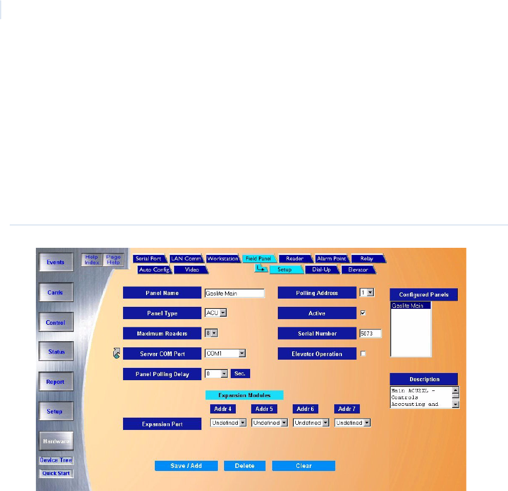
Topa z
User Manual
222
Field Panel Page
The Field Panel pages have three sub-pages.
•Field Panel Setup Page on page 223
•Dial-up Page on page 226
•Elevator Control on page 229
They are used to configure more specific information for the field hardware.
To navigate to the Field Panel pages while in any Hardware page, click the Field Panel tab button at
the top of the window, or from the main Hardware screen click the Field Panel button on the right
side of the screen. The following page displays.
Figure 166.Field Panel
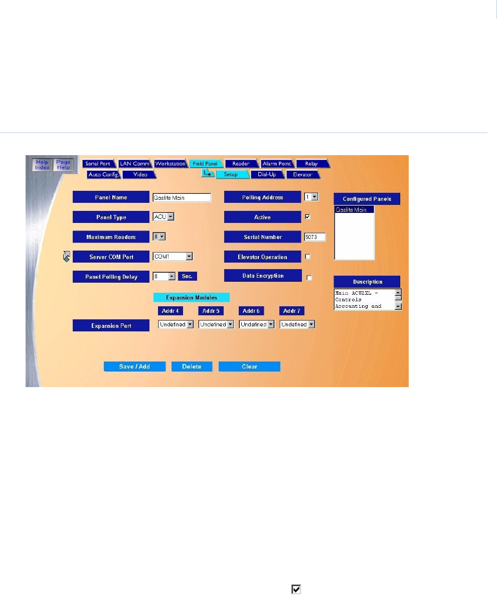
Chapter 9
Hardware
223
Field Panel Setup Page
The Field Panel Setup page is used specifically for adding or modifying new hardware. Here is
where you configure the ACU’s address, serial number, communications port, off line message, and
expansion modules.
Figure 167.Field Panel: Setup
The Field Panel Setup page contains the following information:
Panel Name Enter a name for the field panel (up to 15 characters).
Panel Type The only selection is ACU. In future software versions there will be more selections available to
select from a drop-down list.
Maximum Readers Select the maximum number of readers that this panel may be configured for: 2, 4 or 8.
Polling Address Set the Address of the ACU panel by clicking on the address from the drop-down list. Notice that
the list has numbers 0-9 and then A-F. The address is set in what is called “Hex” or Hexadecimal
numbers with 0-F equivalent to 0-15 respectively. The Polling Address must match the address of
the field panel.
The polling address is manually set with a rotary or DIP switch in the field panel and should have
been set when it was installed. If you are not sure of the address contact the installer of the panel.
Active If the ACU panel is “Active”, click the box to show a check mark.
If the Host PC should start (polling) communicating with the Panel after saving the configuration to
the Host, then click the box to the right to place a check mark in the box. This indicates the field
panel is active.
If no check mark is placed in the box (default), the configuration for the panel can be saved, but the
Host PC will not start polling the panel. At a later time this field can be changed to have the Host
start polling the panel.
This is very useful when you would like to configure panels in advance, before the installation of the
panels or communication connection
Topa z
User Manual
224
How to add a field panel
Note: Before adding a new panel, detailed information on the panel from the installer is required, such as location, type
of panel, address, communication protocol, etc.
Server COM Port From the drop-down list select the computer communication port for the field panel.
COM1 - The physical communication port on the back of the PC.
Note: Click the link arrow to set up an additional Com Port. When setup has been completed,
close the window by clicking Save.
Serial Number The serial number is a unique number for each field panel and is only required for dial-up panels.
The serial number can be found on the documentation that came with the field panel or on the
board inside the field panel.
Elevator Operation If the field panel is going to be used for Elevator Control, click the box to the right placing a
check mark in the box. If not, leave the default of no check mark.
Note: If Elevator Operation has been activated, additional information must be configured on the
Elevator page.
Panel Polling Delay If the TCP/IP or Server COM Port routinely give time-out error messages, you can set a panel
polling delay longer. The default value is zero for dedicated (direct connected) panels. Set the delay
at.5 for all LAN and Dial-up panels.
CAUTION: Never set the delay longer than necessary. For example, if you set the delay to 5 sec.
and the panel is not communicating, the server waits the 5 seconds before giving up and going to
the next field panel. This could delay an event from being reported to the workstation.
Data Encryption If DES encryption is going to be used for data transmission between the field panel and the server,
click the box to the right placing a check mark in the box. If not, leave the default of no check
mark.
Note: The ACURT requires firmware version 7.13.00 or later to allow DES encryption. Consult
the Status display for the current version number that your panel is running. Older panels
may need additional configuration to enable this option. Check with customer support for
assistance.
Expansion Modules Set up the expansion devices that are connected to the ACU on the Expansion Port. You can select
an Input or Output module for addresses 4, 5, 6, and 7. For example, an input module would be a
RIM and an output module would be a RRM. The address is set on the board at time of installation.
If you are not sure of the board address, contact the installer.
Configured Panels This list is used when you wish to select an existing panel to modify or check its configuration. See
“Modify Field Panel” below.
Description Enter the Description of the Field Panel. This can be up to 60 alphanumeric characters describing
the panel location or name of the areas of the building or site that it controls.
For example: “ACU - Building 546 / Rm#2343 - Research Lab & Check Distribution Center”.
Save After all changes have been made to the Panel page, click Save/Add.
One of the following messages displays:
• If “Operation Complete” is displayed, no further changes are needed.
• If “Duplicate Record” is displayed, then the Panel Name has been repeated. Enter a new name
and try saving again.
• If “Duplicate Polling Address” is displayed, then a field panel with the same polling address
already exists. Check to make sure the correct address for the panel was selected.
• If “Operation Failed” is displayed, then a required field was not entered. Enter the field and try
again.
Clear At any point if you wish to clear out all entered information, click Clear.
CAUTION: Clicking Clear before clicking Save deletes newly entered data.

Chapter 9
Hardware
225
1. Click Clear to clear all fields.
2. Fill in the information for the new field panel.
3. After all fields have been added to the Field Panel page, click Save/Add. A message
“Operation Complete” displays.
How to modify a field panel
1. To modify a Field Panel you must first select the panel to be modified. Do this by clicking on
the name of the Field Panel in the list to be modified in the “Configured Panels” window on
the right side of the screen.
2. Wait for the panel's configuration information to be displayed in the main window and the
Panel description to be displayed in the “Description” window below the “Configured Panels”
window.
3. Make any necessary changes to the selected field panel's configuration.
4. Click Save/Add. The message “Operation Complete” displays.
Note: The name of the field panel cannot be modified. You must delete the panel and add it using the new name.
How to delete a field panel
1. To delete a Field Panel from the System you must first select the panel to be deleted. Do this
by clicking on the name of the Field Panel in the list of Configured Panels to be deleted.
Note: To delete a Field Panel, you must first delete all readers, alarm points, and relays on that panel. Then you can
delete the panel.
2. Wait for the panel's configuration information to be displayed in the main window and the
panel's description to be displayed in the “Description” window below the “Configured Panels”
window, and then click Delete.
3. A message “Are you sure you want to delete this record?” displays. Click OK to continue.
4. If a message “Device cannot be deleted with Readers Defined” appears, then shutdown the
field panel and deleted it from the “Not Found” box in Hardware, Auto Configuration.
5. One of the following messages should display.
• If “Operation Complete “is displayed, then no further changes are needed.
• If “Operation Failed” is displayed, then a required field was not entered. Enter the field
and try deleting again.
CAUTION: DO NOT delete a field panel until all associated readers, alarm points and relays have been deleted
from the panel first.
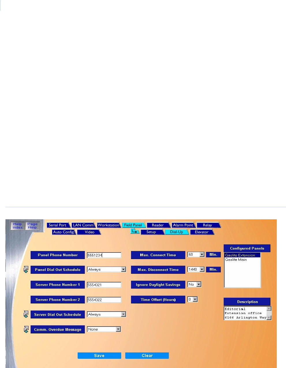
Topa z
User Manual
226
Dial-up Page
The Dial-up Page allows you to configure a dial-up connection from the ACU panel to the server.
Dial-up communication is used when an ACURT Panel is connected to a standard voice dial
telephone line and the server PC has an external US Robotics modem connected to its RS232
communication port. The PC is configured to dial the phone number connected to the ACURT to
download new information. The ACURT panel may also Dial-up the Host PC to report alarms or
download events.
When using Dial-up communications to an ACURT field panel you must install an external modem at
the server. The Topaz Software ONLY supports the (USR) US Robotics 33.6 faxmodem or the 56K
V.90 faxmodem, Sportster modem models 0701 or 0459.
For more information on setting up the external modem set External Modem Setup later in the
chapter
To navigate to the Dial-up page from within the Field Panel pages, click the Dial-up tab button. The
following page displays.
Note: The Serial Number field on the Field Panel, Setup page is required for Dial-up communication.
Note: If a message “Panel with dial-up Server COM Port must be selected” displays, then you have not selected a port
in the Server COM Port field that is configured as a dial-up port. To do this, click OK and then, from the Field
Panel, Setup page, click the link arrow next to Server COM Port. On the Serial Port window, select a Serial Port on
the right. Under Port Connection Device, select the device that is configured for dial-up. Press the Save button.
Figure 168.Field Panel: Dial-Up

Chapter 9
Hardware
227
The Dial-Up page contains the following information:
Panel Phone Number Enter the standard dial-up telephone number that the panel is connected to the server, for
example, “555-1234” (without the quotes). If you must “dial out” to get an outside line first
and you need to first dial a number such as “9” followed by a pause, enter the number as
“9,555-1234”. The comma is needed for a pause. If you must dial long distance, insert a “1”
before the area code, for example, “9,1-799-555-1234”.
Panel Dial Out Schedule Set the Time Schedule that the panel can dial out to the host. For more detailed instructions
on how to set up a Time Schedule, see “Setup - Time Schedules” on page Time Schedule
Page on page 166.
For example, if the time schedule is set for Monday - Friday from 06:00 - 18:00, then after 6
P.M. at night until 6 A.M. and all day Saturday and Sunday the panel would not be allowed to
contact the host PC.
Note: Click the link arrow to set up an additional Time Schedule. When setup has been
completed, close the window by clicking Save.
Server Phone number 1 Enter the primary phone number for the ACU panel to call the Server.
Server Phone number 2 Enter the secondary or backup phone number for the ACU to call the Server.
Server Dial Out Schedule Enter the Time Schedule for the server (Host PC) to dial out to the ACU panel. This time
schedule is used to set when the server can contact the ACU to download new information.
If you only want the download to occur at night you could set the time schedule for Mondays,
Wednesdays, and Fridays from 20:00 - 23:59. This low-traffic time would be the only time
that the server would contact the ACU and download new information to it.
Max. Connect Time Enter the maximum time in minutes that the panel may stay connected. For example, if the
time is set for “15” then at the end of 15 minutes the panel automatically disconnects or
hangs up. The default is 60 minutes.
Max. Disconnect Time Set the Maximum Disconnect Time for the ACU panel. This ensures that the panel is
regularly updated. If the server has not communicated with the field panel for the time set, it
contacts the ACU and sends updates, download history events, etc. The default is 1440
minutes or 24 hours.
Ignore Daylight Savings Select if daylight saving time is to be ignored Yes or No for this ACU only. If the ACU panel
being configured is located in an area that does not observe Daylight Saving Time, then this
field should be set to Yes.
Time Offset (Hours) The Time Offset is the difference (in hours) between the server clock time and the ACU clock
time, to enable you to adjust for time zone differences. For example, if the ACU is located in
another part of the country where the time is 2 hours later, the time offset would be 2 hours.
Comm. Overdue Message From the drop-down list select the message to be displayed anytime communication fails to
the ACU. These messages are from the list of Alarm Instructions configured under Setup /
Alarm Options / Alarm Instructions. For information on how to configure a message, see
Alarm Instruction Page on page 189. For information on how to generate a list all configured
Instruction messages, see Instruction Message Setup Report on page 125.
Save After all changes have been made to the Dial-up Field Panel page, click Save.
One of the following messages displays:
• If “Operation Complete” is displayed, no further changes are needed.
• If “Operation Failed” is displayed, then a required field was not entered. Enter the field
and try again.
Clear At any point if you wish to clear out all entered information, click Clear.

Topa z
User Manual
228
How to set up an external modem
Hardware setup
Note: The Topaz Software ONLY supports the (USR) US Robotics 33.6 faxmodem or the 56K V.90 faxmodem, Sportster
modem models 0701 or 0459.
Note: You do NOT need to install the modem or drivers in Windows.
When you power up the external modem LEDs AA, TR, and CS should be illuminated, all others
should be off.
Software setup
After installing the modem make sure dial-up panels are configured in the Topaz server software as
SCP Dial-Up, set to 9600 baud, No parity and Active.
From Control and Service Functions, you must setup the modem. Choose Initialize - Test Modem
and Serial Port and say Go. The modem LEDs SD and RD should blink several times. This sends
the correct AT commands necessary for the modem to work correctly.
Note: We recommend that you use a minimum of two dial-up ports/modems for data and alarms. As the system grows or
as the alarm load increases, it may be necessary to use more Server modems to handle the traffic.
The Topaz systems administrator also needs to know the ACURT2 or ACURT4 Controller’s Serial
Number.
For additional information on dial-up communication, see Dial-up Modem (Optional) in the Topaz
Hardware Installation User Guide.
The switches on the back of the modem must be configured with
switches 5 and 6 set to the UP position, all others should be in the
down position as shown to the right.

Chapter 9
Hardware
229
Elevator Control
The Elevator Control Software (ECS) is an enhancement that allows Topaz to manage floor access.
This feature is turned on in the Field Panel configuration page. Topaz associates cab and floor
numbers with a security area and a relay.
Once a field panel is configured for the elevator control function, it can only be used for elevator
control. The relays on an elevator control field panel are always in the activated (on) state. A valid
access deactivates the relay(s) for the authorized floor(s) on the cab being used.
The Elevator Control Software can support up to all 32 readers configured as elevator cabs even if
the cabs are in different buildings. Elevator cabs used in conjunction with this feature should be
equipped with card readers, which may or may not have keypads. Two (2) elevator cabs are
supported per ACURT2 field panel and four (4) elevator cabs are supported per ACURT4 field panel.
ECS controls access to different floors for each badge holder using security area (s)/group and time
schedules per card per floor. The software verifies that the cardholder has access to the cab and
floor combination. If access is allowed, the system sends a momentary relay deactivation command
to the elevator control panel.
Configuring the Elevator Control
Configuring the Elevator Control is a five-step process:
1. Install the specific hardware that supports elevator control. Install card readers in the elevator
cabs and connect the control relays as the interface to the elevator control panel.
2. Define the field panel configuration used with the elevator cabs. You can configure any
reader on an elevator ACURT2 or ACURT4 as an elevator cab reader. There is no special
elevator configuration needed in the Reader Setup.
Note: Once an ACU is configured for Elevator Control, it can only be used for Elevator Control.
3. Configure a Security Area for each floor that the elevator cab(s) access.
4. Define the elevator cabs and floors accessible by the cab. Up to 40 floors can be configured
by adding two (2) RRMs (address 6 and 7) to the ACURT4. For more information on this step,
see Elevator Floor Definition Page on page 233.
5. Setup and configure the Elevator Control itself.
Topaz Field Panels and Elevator Control
The ACURT2 field panel has 4 onboard relays and the ACURT4 has 8 onboard relays. The ACU can
have two (2) RRMs added for a maximum of 36 or 40 relays maximum for elevator control. The relay
numbering will be different depending on which ACU is used (see the relay numbering chart below).
The example below is using an ACURT4 with one RRM (addressed #6). There are 3 Elevator Cabs
controlling 4 floors each. Each Relay would be given a Security Area for access authorization. Each
elevator cab must have its own reader. When a card is read in Elevator Cab 2 and the user has
access to Areas “Records” and “Accounting” then only relays 4 and 5 would operate.
Note: Only RRMs addressed 6 and 7 can be used for ACUs configured for elevator control.
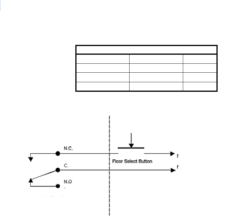
Topa z
User Manual
230
Elevator Relay Numbering
Elevator Relay Interface
Note: When an ACU is used for Elevator Control, all its relays are set to energized when not selected. If the ACU were
to fail, all floors are enabled. (Fail Safe)
Note: Some older elevators require the relay to be activated longer. If this is necessary, in the software set the Door
Bounce Timer to 2 seconds. This should take care of any additional delay required by the elevator.
Relay Numbering for Elevator Control
ACURT2 ACURT4
Onboard ACU 0 – 3 0 – 7
RRM Address 6 4 – 19 8 – 23
RRM Address 7 20 - 35 24 - 39
Elevator
Relay Wiring
UTC Fire & Security Side
UTC Fire & Security
Relay
Elevator Side
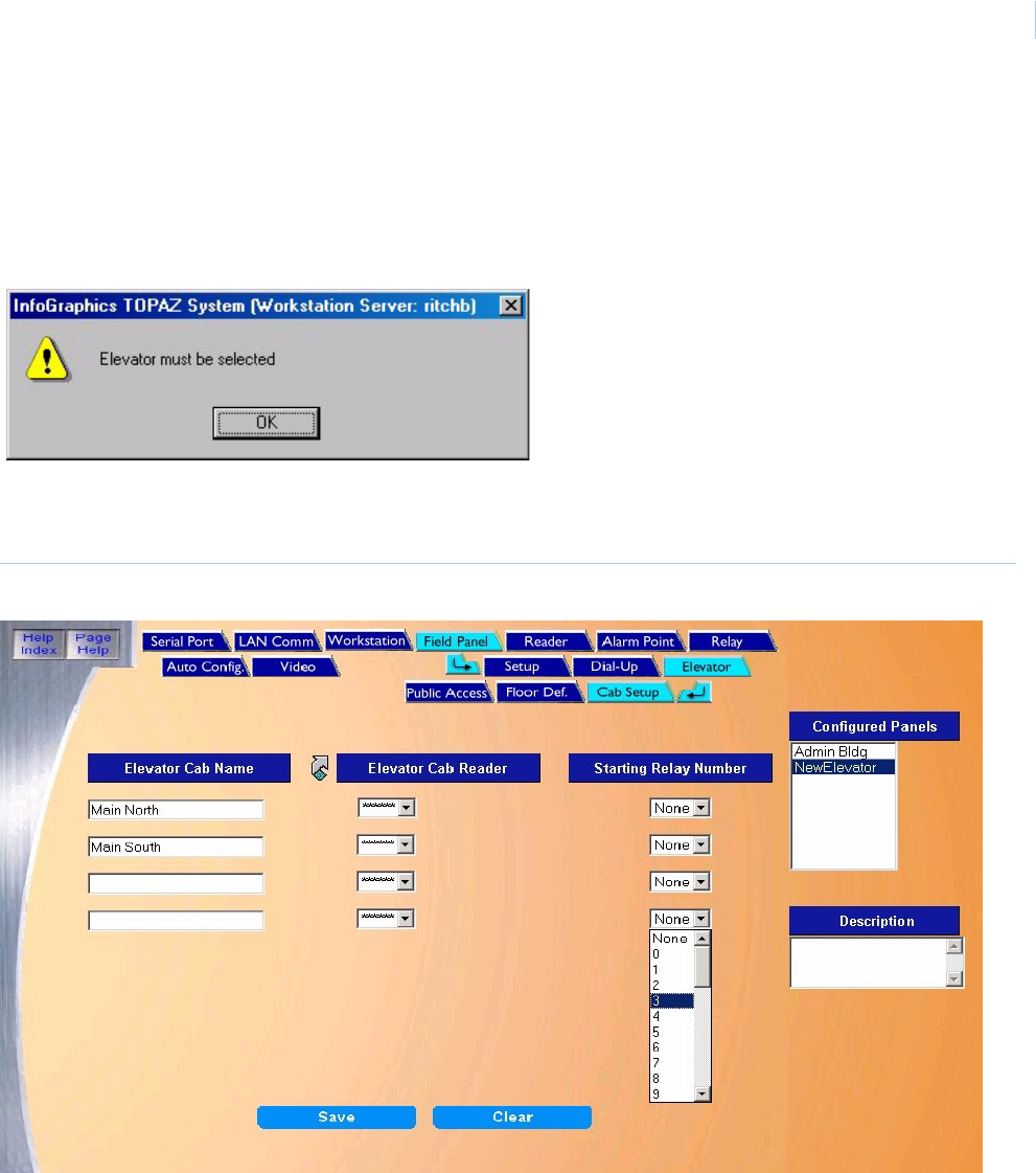
Chapter 9
Hardware
231
Elevator Cab Setup
To navigate to the Cab Setup page from any page in the Field Panel Setup pages, on the Setup –
Field Panel page, first make sure you have a panel selected and Elevator Operation selected. If
you don’t, when you try to select Setup – Field Panel – Elevator, the “Elevator must be selected”
message displays:
After selecting Elevator Operation, click the Elevator tab button at the top of the window. The
following page displays.
Figure 169.Elevator: Cab Setup
Note: If you entered data on a new field panel to be used with the elevator cab, you must first save the data on the panel
before you can assign cab readers to this elevator device.

Topa z
User Manual
232
The Cab Setup page contains the following information:
Elevator Cab Name Enter up to 21 alphanumeric characters for the name of the elevator cab.
Elevator Cab Reader From the drop-down list select the reader that assigned to the elevator cab.
Note: Click the link arrow to set up an additional Reader. When you click Save, the
window closes and you can continue working in Elevator Cab setups.
Note: If you configure a new field panel from the Reader Setup page, you must save
that new panel’s data. If you do not, you cannot attach that reader to the elevator.
Starting Relay Number Select from the drop-down list the first relay for that cab. For a given cab, the relays must
be assigned in sequence and a single relay number cannot be used for more than one cab.
The relay numbers range from 0 to a maximum of 35, for a maximum of 36 relays per
ACURT2 and from 0 to a maximum of 39, for a maximum of 40 relays per ACURT4 field
panels. For example, if you have 3 elevator cabs serving the same 9 floors of a building,
you might assign relays 0-8 for cab 1, relays 9-17 for cab 2, and relays 18-26 for cab 3.
Note: The drop-down list contains only those relays that are appropriate for the selected
ACURT2 or ACURT4 panels.
Save After all changes have been made to the Cab setups page, click Save.
One of the following messages displays.
• If “Operation Complete” is displayed, no further changes are needed.
• If “Duplicate Record” is displayed, then the Elevator Cab Name has been repeated.
Enter a new name and try again.
• If “Operation Failed” is displayed, then a required field was not entered. Enter the field
and try again.
Clear At any point if you wish to clear out all entered information, click Clear.
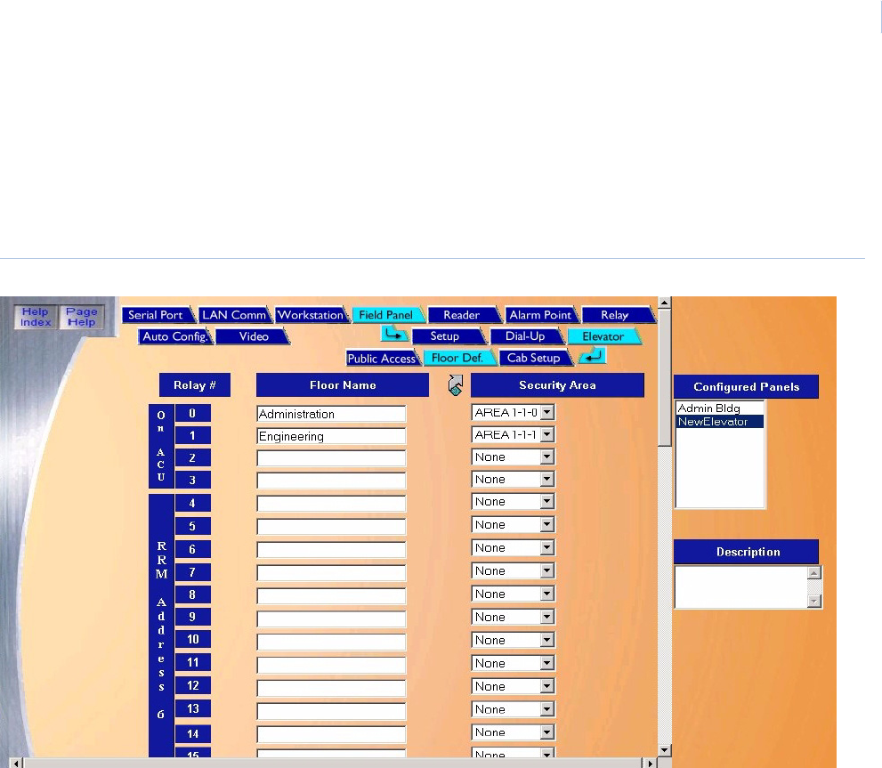
Chapter 9
Hardware
233
Elevator Floor Definition Page
The Elevator Floor Definition page allows you to setup the relay links to floors and Security Areas
for access authorization. To navigate to the Floor Definition page from any page in the Field Panel
Setup pages, click the Elevator tab button at the top of the window and then click the Floor Def. tab
button. The following page displays.
Figure 170.Elevator: Floor Definition
The column of relay #s on the left of the page are Relay #s in the ACU panel. Floor Names and
Security Areas for authorization are assigned to each relay that is used
The Floor Definition page contains the following information:
Relay # Topaz allows up to 36 relays (0-35) in the ACU panel in the column on the left of the window. The
blue panel on the left of these relays indicates the location and relay number on the selected
panel. This makes linking the correct floor to the correct relay easier. You need to know which floor
button in the elevator cab corresponds to which ACU relay. If needed, use the scrollbar on the right
side of the window to navigate down to all 36 relays.
Note: Different cabs may skip relays/floors.
Floor Name Enter the Floor Name (up to 32 characters) to identify the floor that the relay is linked to. For
example, “Floor 2".
Note:
• The name of the security area for elevator control must be a number such as “3”, not “Floor 3”.
• Click the link arrow to set up an additional Security Area. When setup has been completed,
close the window by clicking Save and continue working in the Elevator Floor screen.

Topa z
User Manual
234
Assigning relays to the floors
For each relay that electronically selects a requested floor enter a name for that floor. For information
about wiring the ACU, see the Topaz Hardware Installation Guide. Next to the floor name select the
Security Area that belongs to this floor. A Security Area must be configured for each floor controlled
by the panel. Assign the floor name and Security areas in sequential order.
If there are no Security Areas in the drop-down list, then you must first create your site’s security
areas by going to Setup page, then Security Areas. For more details on how to configure a Security
Area, see Security Area Page on page 168.
Security Area Select the pre-configured Security Area from the drop-down list by clicking on the arrow to the right
of the Security Area field and then click the name to select the Security Area for authorization.
If a Security Area is not selected before saving the page, the Floor Name is not saved.
Configured Panels You can select a field panel by clicking on the name listed.
Description You can enter or change the description of this field panel.
Save After you have completed assigning the floors and Security Areas, click Save.
One of the following messages displays:
• If “Operation Complete” is displayed, then no further changes are needed.
• If “Operation Failed” is displayed, then a required field was not entered. Enter the field and try
again.
Clear At any point if you wish to clear out all entered information, click Clear.
CAUTION: Clicking Clear before clicking Save deletes newly entered data.
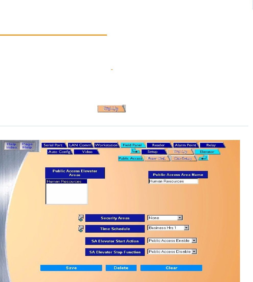
Chapter 9
Hardware
235
Elevator Public Access
The Elevator Public Access page allows you to define multiple public access scenarios for
elevators. At the start of the time schedule, elevator buttons associated with the selected security
areas are enabled allowing anyone to have access to those elevator floors.
For an overview on the Elevator Control, see Elevator Control on page 229.
To navigate to the Public Access page, from any page in the Field Panel setup pages, click the
Elevator tab button at the top of the window and then click the Public Access tab button and the
following page displays.
Note: After clicking the Public Access tab, the tabs for Dial-Up, Elevator, Floor Def., and Cab Setup are no longer
available and appear like this example, . To access these tabs again you must click the Field Panel /
Setup tab.
Figure 171.Elevator: Public Access
The Public Access page contains the following information:
Public Access Elevator Areas This is a list of Public Access Elevator Areas that have been configured. If you have not
configured any areas yet, the list is empty. To modify an existing area, click the name in the
list to select it.
Public Access Area Name Enter the name of up to 26 characters for the public access area. This indicates the
Security Area open to the public during the selected time schedule.

Topa z
User Manual
236
Security Areas Select a Security Area from the list by scrolling through the list and clicking on the name of
the area so it is highlighted. Only elevator security areas appear in this list.
Note: Click the link arrow to set up an additional Security Area. When setup has been
completed, close the window by clicking Save/Add.
Time Schedule Select from the drop-down list the Time Schedule for this elevator public access area. The
Default is “Always”.
Note: Click the link arrow to set up additional Time Schedules. When setup has been
completed, close the window by clicking Save/Add.
SA Elevator Start Action There are two actions that are available for Elevator Stop Function. Select the action that
occur when the Time Schedule ends from the drop-down list. Options include:
• Public Access Enable
• Public Access Disable (default)
SA Elevator Stop Function There are two actions that are available for Elevator Stop Function. Select the action that
occur when the Time Schedule ends from the drop-down list. Options include:
• Public Access Enable
• Public Access Disable (default)
Save Once all the information has been added, click Save/Add.
One of the following messages should appear:
• If “Operation Complete” is displayed, no further changes are needed.
• If “Duplicate Record” is displayed, then the Public Access Name has been repeated.
Use a new name and try saving again.
• If “Operation Failed” is displayed, then a required field was not entered. Enter the field
and try saving again.
Clear At any point if you wish to clear out all entered information, click Clear.
CAUTION: Clicking Clear before clicking Save deletes newly entered data.
Delete Click to delete the selected public access area from the database.

Chapter 9
Hardware
237
How to add a public access area
1. Click Clear to clear all fields.
2. Fill in the information for the new public access area.
3. After all fields have been added to the Public Access page, click Save/Add. A message
“Operation Complete” displays.
How to modify a public access area
1. To modify a public access area, select the name of the area to modify from the “Public
Access Elevator Areas” window.
2. Make any necessary changes to the other fields on the Public Access page.
3. Click Save. A message “Operation Complete” displays.
How to delete a public access area
1. To delete a public access area from the System, select the area to be deleted by scrolling
through the Public Access Elevator Areas window and clicking on the name of the area.
2. Wait for the configuration information to be displayed in the main window.
3. After making sure that the correct area to delete is selected, click Delete.
4. A message “Are you sure you want to delete this record?” displays. Click OK to continue. A
message “Operation Complete” displays.
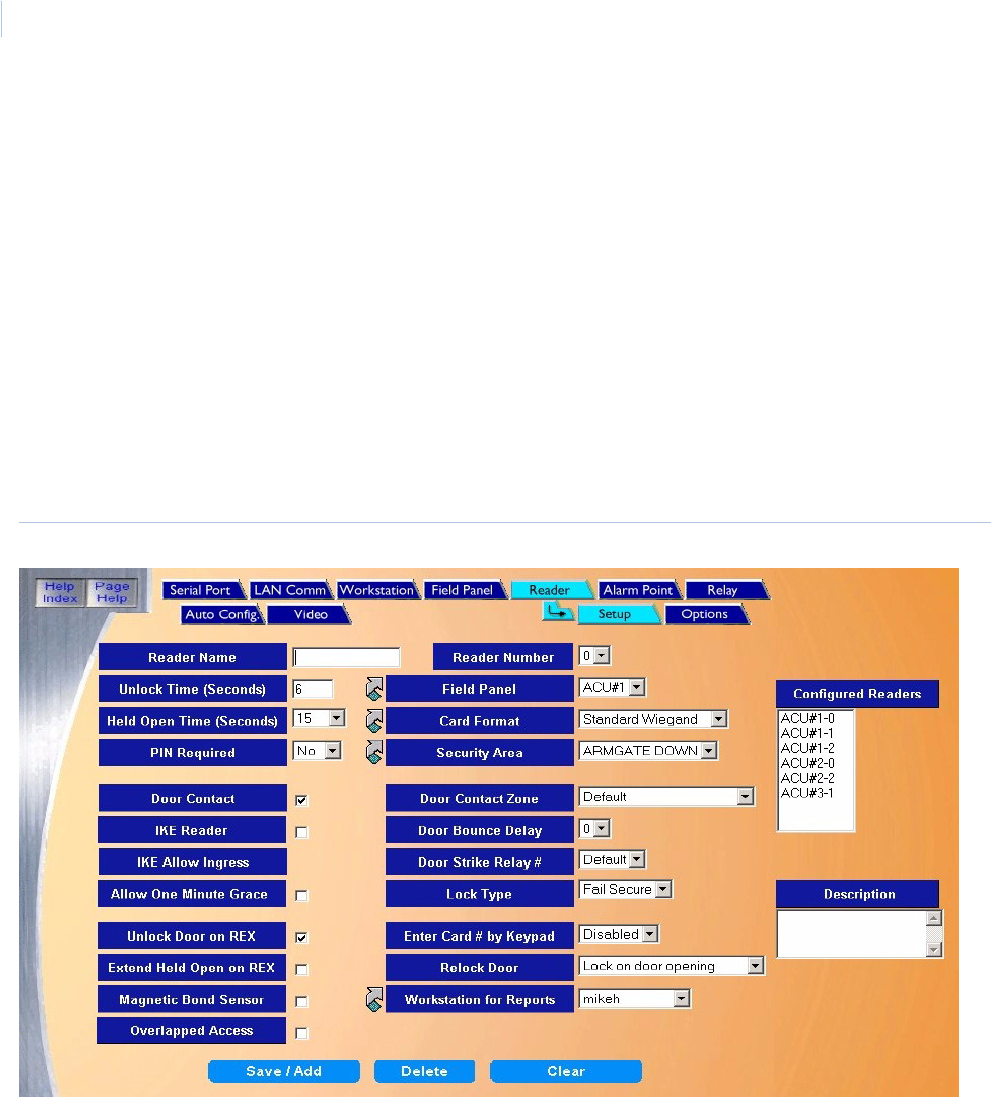
Topa z
User Manual
238
Readers
The Reader pages allow you to add, modify, or delete readers, including configuring the reader
address, name, description, unlock time, security area, etc.
There are two reader pages
•Reader Setup Page on page 238
•Reader Options Page on page 243
Reader Setup Page
To navigate to the Reader Setup page from any Hardware page click the Reader tab button in the
navigation bar at the top of the main window, or from the main Hardware screen click the Reader
button on the right side of the screen. The following page displays.
Figure 172.Reader: Setup
The Setup page contains the following information:
Reader Name Enter the Reader Name of up to 12 alphanumeric characters, for example, “Lobby Door” or
“Parking Gate”.
Reader Number Select the Reader Number from the drop-down list of 0-7 by clicking on the number. This
number is the address where this reader is connected on the reader board. If you are not
sure of the address contact your installer.
Unlock Time (Seconds) The Unlock Time is the amount of time the door lock is to stay unlocked allowing the
cardholder to open the door. Type the number of seconds directly into this field. The range
of times that can be entered is 0-255. The default is 6 seconds.

Chapter 9
Hardware
239
Field Panel From the drop-down list select the ACU Panel that the reader communicates with or is
connected to. If you are not sure of which panel the reader is connected to contact the
installer.
Note: Click the link arrow to set up an additional ACU Field Panel. When setup has been
completed, close the window by clicking Save.
Held Open Time (Seconds) The Held Open Time is the number of seconds that the door can remain open after a
granted access before an alarm is generated. The options are 15, 30, 45, 60, 90, 120, 180,
240, 300, 600, or 999 seconds. The default is 15 seconds.
Note: For the Held Open Time option to work, a door-monitoring device must be
installed, connected, and configured.
Card Format If you are using access cards with this Topaz system, then select the Card Format from the
drop-down list. If you are not sure of the format on your cards contact the installer. The
possible options are:
• Standard Wiegand
• Standard Mag Stripe
Note: If your card format is not in Standard Wiegand or Mag Stripe format, you need to
set up a Variable Card Format. Click the link arrow to set up a Variable Card
Format. When setup has been completed, close the window by clicking Save.
Pin Required If there is a keypad on the reader being configured and you wish to require the cardholder
to use a PIN, select Yes. If the reader does not have a keypad or the PIN is not going to be
used, select No.
Security Area Select the Security Area from the drop-down list of predefined security areas that the
reader is associated with. For example, if the reader is the Main Door to the Research Lab,
then it may be assigned to an area called “Research Lab”. Later when giving access
authority to a cardholder they may be given the “Research Lab” as an area of authorized
access.
Note: Click the link arrow to set up additional Security Areas. When setup has been
completed, close the window by clicking Save.
Door Contact Select this box if the door that the reader is controlling has a contact and you wish that
contact to be used to monitor the door status. The default is to have a checkmark in this
box. If the door contact is not going to be used, click the check box to remove the check
mark.
Note: On a paired reader (two readers on one door), the two readers share the same
door contact alarm; therefore when wiring a paired reader:
- the reader with the higher address should use the door contact alarm of the
reader with the lower address;
- the reader with the lower address should use the default door contact alarm.
Door Contact Zone Select the alarm point to be used as the door contact. By default the field panel uses the
zone at the reader.
Paired Readers If two readers are connected to the same door, on opposite sides of the door, you can
configure them as “Paired Readers”. To do this, for each door:
• Both readers must be controlled by a single ACU.
• Door Contact must be used.
• Select the same Door Contact Zone for both readers.
IKE Reader If the reader you are configuring is an IKE reader, you need to check this box so that the
reader properly activates and deactivates alarms.

Topa z
User Manual
240
Door Bounce Delay Door Bounce Delay allows you to select a delay from 1-7 seconds for the forced open
alarm. This prevents a false alarm from occurring, for example when the door closes to
quickly and the pressure from the hydraulic door closer allows the door to bounce open
again before securing.
Note: If using Elevator Control, some older elevators require the relay to be activated
longer. If this is necessary, in the software set the Door Bounce Timer to 2
seconds. This should take care of any additional delay required by the elevator.
IKE Allows Ingress This field only appears if IKE Reader is selected above. In some security applications,
alarms can only be masked from inside the area. When this is the situation, and this IKE
reader is used to enter the security area, click the check box. The IKE reader allows the
authorized cardholder into the area, but does not mask the alarms.
Door Strike Relay # If you are using a relay other than the default selection for the door lock, select a relay
number for the door strike by clicking on a relay number in the drop-down list. The default
selection for reader 0 uses relay 16 located on the ACU, reader 1 uses relay 18, and so on.
For more information on relay addressing, see Elevator Control on page 229.
Note: On a paired reader (two readers on one door), the two readers share the same
door strike relay; therefore when wiring a paired reader:
• the reader with the higher address should use the door strike relay of the
reader with the lower address
• the reader with the lower address should use the default door strike relay.
Allow One Minute Grace Select this option if you want the Door Held Open timer to extend for one additional minute
after the normal Held Open time. During this time the reader's LEDs (and buzzer if
equipped) signals a violation. If the controlled door re-closes before the minute expires, the
door Held Open Alarm cancels and is never sent to the Workstation.
Lock Type There are two types of lock that are used in different situations depending on how the lock
should respond to a power failure.
• Fail Safe – Select if the electric lock installed requires power to keep the door locked. If
power were to fail the door would then automatically unlock.
• Fail Secure – Select if power would be required to unlock the door. In the normal
condition with no power to the lock it would be locked. In the event of a power failure
the door would remain locked.
The above action requires the panel to have firmware version 5.79 (5 series) or 6.10 (6
series) or higher.
The first two of these options require a door contact to monitor door condition.
Unlock Door on REX Select this option when you want the reader door to unlock when a person initiates a
Request To Exit (REX) the area. A button, motion detector, or other device may activate the
Request to Exit. A Request to Exit is required so that a Forced Open Alarm is not
generated when a cardholder exits an area that does not have an exit keypad or reader, but
does have a door contact.
If the door is to unlock when the Request to Exit is generated, click the box to the right. The
door responds the same as if a cardholder has entered a valid card/PIN to access the area.
If the door has a crash bar which allows exiting without unlocking the door, remove the
check mark from this box. This allows the door to be opened from the inside but the alarm
is masked allowing the person to exit without generating a Forced Open Alarm.

Chapter 9
Hardware
241
Enter Card # by Keypad The Enter Card # by Keypad allows the cardholder to enter their card number by using the
keypad. The number of digits set in this field represents the number of digits that are
required for a card number to be considered complete. For example, if the card number is 4
digits (0000 - 9999) or less, the field should be set at 4 digits. A cardholder whose card
number is less than required number must enter leading zeros, or can use the * key (for
example, if the card number is 0032, you can enter 32*). The * key is only used for leading
zeros, not trailing zeros, for example, it is not required for 3200.
The possible options are 4 Digits, 5 Digits, and 6 Digits. The default is Disabled.
Extend Held Open on REX Select this option if you want the Held Open Timer to automatically extend for as long as
the Request to Exit (REX) input is activated. The Held Open timer does not start counting
until the REX is released. Select the feature by clicking on the box placing a check mark in
it.
If not selected the Held Open Timer starts counting as soon as the door opens, and the
timer expires even if the REX stays activated with the door open. At the end of the time, an
alarm would be generated.
Relock Door Relock Door
• After Door Opening – Select if you want the door to be relocked as soon as the door
opens.
• After Door Closes – Select if you want the door to relock only after the door closes.
This option (if selected) keeps the door locked even after the set lock time and only
relocks the door after the door is closed. This option is used for dead bolt and other
similar type locks.
• Relock Door on Strike Timeout - Select if you want the door to remain unlocked (even
if the door is still open) until the strike timer expires. The door cycle also ends at that
time. End of cycle means that alarms are immediately enabled, including the 'forced
open' alarm for doors with a door contact.
Note: If the door is monitored by an alarm contact, and the reader is set for 'Overlapped
Access', and is open at the end of the door strike timer, then the 'Held Open' time
is used to end the door cycle, and a new card read re-fires the door strike and
restarts the timers.
Magnetic Bond Sensor Select this option when you want the third alarm point connection to work with some type of
latch monitor sensor such as a magnetic Lock. When selected, alarm point number Z02 is
wired to the latch monitor. When not selected it may be used as a normal alarm point.
Workstation for Reports Select from the drop-down list the server or Workstation to which the reports from the
reader is sent.
Note: Click the link arrow to set up an additional Workstation. When setup has been
completed, close the window by clicking Save.
Overlapped Access Normally after an access is granted, the system must see the door closed before the reader
resets for the next cardholder. When this option is selected by placing a checkmark in the
box, the reader resets immediately after the first access request is made by a cardholder,
allowing the next cardholder to access the reader without closing the door.
For this feature to work properly, a door contact switch should be installed and connected to
the system to monitor the condition of the door.
Description Enter the description of the reader, up to 50 alphanumeric characters. This could describe
the location and area the reader protects.
Topa z
User Manual
242
How to add a reader
1. Click Clear to clear all fields.
2. Fill in the information for the new reader.
3. After all fields have been added to the Reader Setup page, click Save/Add. A message
“Operation Complete” displays.
How to modify a reader
1. Select the reader to be modified from the Configured Readers list.
2. Make all desired modifications to the reader.
3. Click Save. A message “Operation Complete” displays.
How to delete a reader
1. To delete a reader from the system you must first select the reader to be deleted. Do this by
clicking on the name of the reader to be deleted in the Configured Readers window to the
right of the main window.
2. Wait for the reader's configuration information to be displayed in the main window and the
reader description to be displayed in the Description window below the Configured Readers
window.
3. After making sure that the correct reader to delete is selected, click Delete.
4. A message “Are you sure you want to delete this record?” displays. Click Yes to continue.
5. A message “Operation Complete” displays.
6. The reader is removed from the list of Configured Readers.
Note: When deleting a reader the Alarm points for the reader remains in the database. If the reader is added back into
the system, the alarm points are reassigned to the reader, unless you previously deleted the alarm points.
Save After all changes have been made to the Reader Setup page, click Save.
One of the following messages displays.
• If “Operation Complete” is displayed, then no further changes are needed.
• If “Duplicate Record” is displayed, then the Reader Number has been repeated. Enter
a new number and try again.
• If “Operation Failed” is displayed, then a required field was not entered. Enter the field
and try again.
Clear At any point if you wish to clear out all entered information, click Clear.
CAUTION: Clicking Clear before clicking Save deletes newly entered data.
CAUTION: DO NOT delete a reader until all associated alarm points, cameras and relays have been deleted from
the reader first.
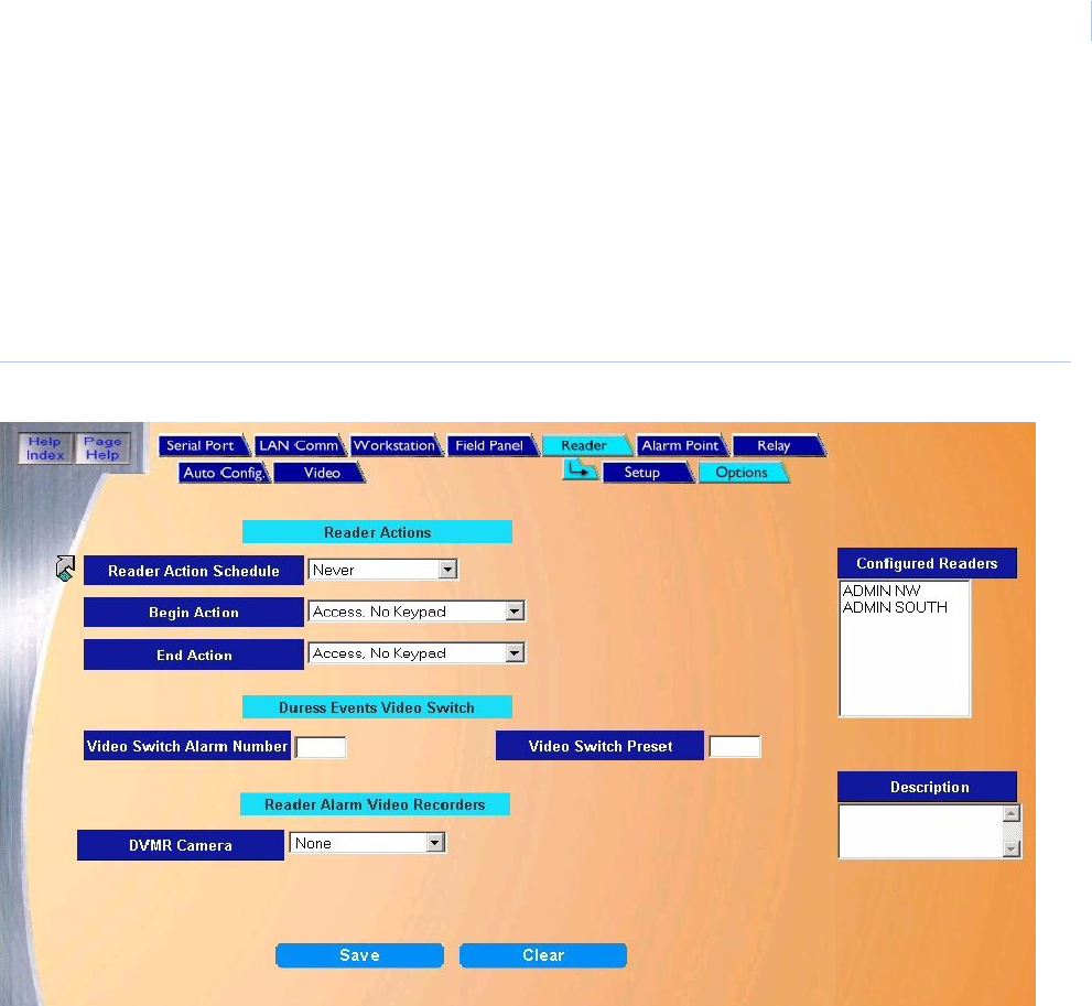
Chapter 9
Hardware
243
Reader Options Page
The Reader Options page allows you to set up automatic actions for the reader to perform and
assign video switchers and digital video recorders to the reader.
To navigate to the Reader Options page from any Setup page click the Reader tab button in the
navigation bar at the top of the window and then the Options tab button. The following page
displays.
Figure 173.Reader: Options
The Options page contains the following information:
Reader Action Schedule Select the Time Schedule for the Reader Action Schedule. This allows the reader to enter the
selected action at the Begin Action (beginning of the time schedule) and enter another
selected Action at the End Action (end of the time schedule).
Note: Click the link arrow to make a new schedule. When setup has been completed,
close the window by clicking Save.

Topa z
User Manual
244
Begin/End Actions The actions available for Begin Actions and End Actions are as follows:
• Access, No Keypad - Only a valid card for access is required.
• Access, Keypad - Only a keypad is required for access.
• Access, Company Mode - Access is granted if the Company Code on the card is correct.
• Access, Facility Code - Access is granted if the Facility Code on the card is correct.
• Lock Door - Door locks and no access is granted for any cardholder.
• Unlock Door- Door unlocks.
• Conditional Unlock - This options keeps the door locked until a cardholder with
Authorized for Conditional Unlock presents their card.
• Turn On Keypad Enter - Only a valid PIN is required for access.
• Turn Off Keypad Entry - A valid PIN is not required for access.
Duress Events Video
Switcher
Video Switch Alarm Number Enter the alarm number of the video switcher that should be activated when the reader's
duress alarm is generated. This field requires a video switcher alarm input.
For more information on duress, see Duress on page 391.
Video Switch Preset To activate a preset on the video switcher when the duress alarm is activated, enter the
preset number of the video switcher that is to be activated.
Reader Alarm Video
Recorder
Topaz allows cameras on digital video recorders to be linked to readers so that alarms
generated at a reader can be recorded for investigation. See Video Recorder on page 258 for
information on configuring a Digital Video Recorder.
Note: Only alarms are recorded for investigation, so only those reader events that display
in the alarm window are tagged for recording.
DVMR Camera This is the DVMR camera that is associated with an alarm event generated by this reader.
Select the camera from the drop-down list of available cameras. See How to add a new video
camera on page 262 for information on configuring a camera.
Save After all changes have been made to the Reader Options page, click Save.
One of the following messages displays.
• If “Operation Complete” is displayed, then no further changes are needed.
• If “Duplicate Record” is displayed, then the Reader Name has been repeated. Enter a
new name and try again.
• If “Operation Failed” is displayed, then a required field was not entered. Enter the field
and try again.
Clear At any point if you wish to clear out all entered information, click Clear.
CAUTION: Clicking Clear before clicking Save deletes newly entered data.
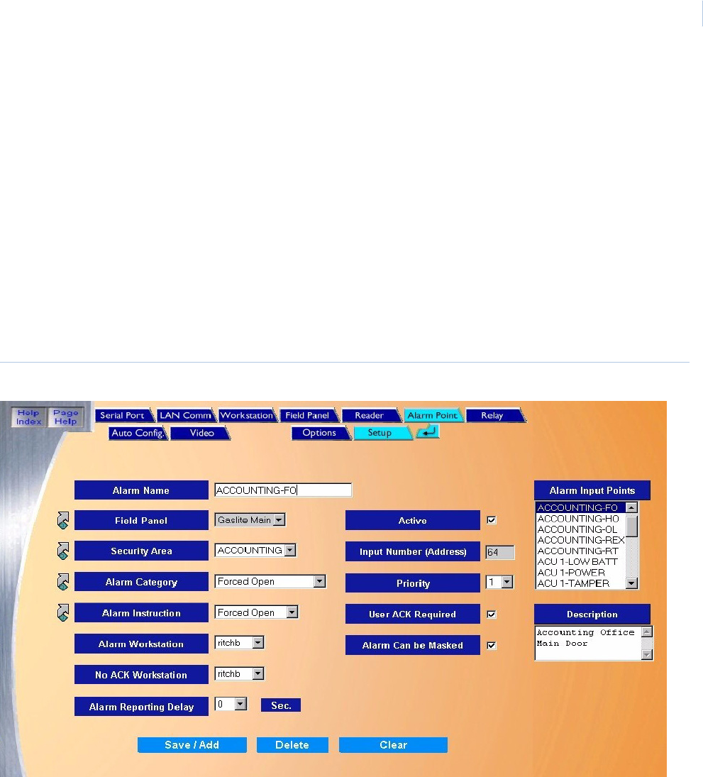
Chapter 9
Hardware
245
Alarm Point
The Alarm Point page is used to add, modify, or delete existing alarm points. The Alarm Point page
has two sub-pages, “Setup” and “Options”. They are used to configure more specific information for
the alarm point.
•Alarm Point Setup on page 245
•Alarm Point Options Page on page 248
Alarm Point Setup
To navigate to the Alarm Point page within the Hardware pages, click the Alarm Point tab button at
the top of the window, or from the main Hardware screen click the Alarm Point button on the right
side of the screen. The following page displays.
Figure 174.Alarm Point: Setup

Topa z
User Manual
246
The Setup page contains the following information:
Alarm Name The Alarm Name field is used to designate the name to be used for an alarm point. it can contain
up to 26 characters. For example, “Emergency Exit Door S/E”
Note: Each name must be unique from any other. No duplicate names are allowed.
Field Panel The Field Panel field is used to indicate the ACU that controls this alarm point. Select the Field
Panel from the drop-down list of pre-configured panels.
Note: To configure a field panel, click the link arrow to the left of the Field Panel field.
Configure the Field Panel and click Save.
Security Area The Security Area field is used to assign a security area to the alarm point. It is selected from a
drop-down list of configured Security Areas.
Note: To configure a Security Area, click the link arrow to the left of Security Area field.
Configure the Security Area and click Save.
Alarm Categories The Alarm Categories field indicates the category to which this alarm point is to be assigned. It is
good to group alarms points into categories like “Held Open” or “Motion Det.” so that the group
can be recalled from history. It is selected from a drop-down list.
Note: To configure an Alarm Category, click the link arrow to the left of Alarm Category field.
Configure the Alarm Category and click Save.
Alarm Instructions The Alarm Instruction field contains the name of one of the configured Instruction Messages. It is
selected from a drop-down list.
Note: To configure an Alarm Instruction, click the link arrow to the left of Alarm Instruction field.
Configure the Alarm Instruction and click Save.
Alarm Workstation The Alarm Workstation field links the alarm to a workstation where it reports for
acknowledgement ad processing. It is selected from a drop-down list.
No Ack Workstation The No Ack Workstation field is used to route an active alarm if it is not acknowledged at its usual
workstation. Select the workstation from the drop-down list of configured workstations. If your
system does not have a workstation assigned, the default is the server.
Active The Active field is used to indicate if the alarm point is active. Place a check mark in the box
indicating alarm point is connected and the system is to start monitoring the point. The server
does not start monitoring the point until the configuration is saved. If the point should not be
monitored until a later time, leave the box unchecked. This allows the system to be programmed
while the hardware is being installed without generating constant alarms.
Input Number (Address) The Input Number (Address) field is used to indicate the location on the ACU to which the alarm
is wired. If you are not sure what the alarm number is, contact the installer.
Priority The Priority field indicates the level of importance this alarm should have. The range is 1 to 16.
The default is to have 16 the highest priority. To change this to 1 being highest, click the Priority 1
is Highest Priority check box on the Site Settings page. See Priority 1 is Highest Priority Alarm on
page 176.
For example, a Smoke Detector alarm might be given a higher priority number so it would be
reported ahead of other alarms. The highest priority appears at the top of the list in the alarm
queue. The Duress alarm defaults to a priority 15 due to the usual setting that priority 16 is the
highest priority.
User ACK Required The User ACK Required field is used to require acknowledge by the operator when the alarm is
generated and displayed on the Workstation.
If the operator does not acknowledge the alarm in a predetermined time limit, the Workstation
displays Operator Failed To Acknowledge and logs it to the event file. After acknowledgement the
operator may also enter comments to be logged to history.
If you uncheck this box, the operator is not required to acknowledge the alarm point. The alarm is
placed in the queue, but no enunciator sounds at the workstation.

Chapter 9
Hardware
247
How to add an alarm point
1. Click Clear to clear all fields.
2. Fill in the information for the new alarm point.
3. After all fields have been added to the Alarm Point Setup page, click Save/Add. A message
“Operation Complete” displays.
How to modify an alarm point
1. To modify an alarm point, select the name of the point from the “Alarm Input Points” window.
2. Make any necessary changes to the Alarm Point fields.
3. After all changes have been made to the Alarm Point Setup page, click Save. A message
“Operation Complete” displays.
How to delete an alarm point
1. To delete an Alarm Point from the System, select the Alarm Point to be deleted by scrolling
through the Alarm Input Points window and clicking on the name of the Alarm Point.
Alarm Can Be Masked The Alarm Can Be Masked field is used to allow the alarm to be masked by authorized personnel.
Click the box to the right placing a check mark in the check box. If the alarm point should never
be masked, then leave the default with no check mark.
CAUTION: Alarms that report the state of an alarm such as Alarm Off line or Tamper should not
be masked. Allowing these status alarms to be masked reduces the security and effectiveness
of the system.
Description The Description field allows you to enter other information about this alarm point. The field allows
up to 256 alphanumeric characters. For example, “High Temp in Computer Room Build-23” or
“Emergency Exit door By Southwest Stairwell - Build #501”. You could even include an address
like “Roof Hatch Southwest Corner - 254 E. Main St.”
Alarm Reporting Delay The Alarm Reporting Delay field is used in conjunction with Keypad Masking, etc., where the
keypad is located inside the protected area. For example, if the alarm point being configured is
the door you would use to enter the area, the alarm can be delayed for between 1and 255
seconds to give you time to enter the area and deactivate the alarms before they are reported to
the operator. Select the number of seconds the alarm report should be delayed from the drop-
down list.
Save After all changes have been made to the Alarm Point Setup page, click Save.
One of the following messages displays.
• If “Operation Complete” is displayed, then no further changes are needed.
• If “Duplicate Record” is displayed, then the Alarm Number has been repeated. Enter a new
name and try again.
• If “Operation Failed” is displayed, then a required field was not entered. Enter the field and
try again.
Clear At any point if you wish to clear out all entered information, click Clear.
CAUTION: Clicking Clear before clicking Save deletes newly entered data.
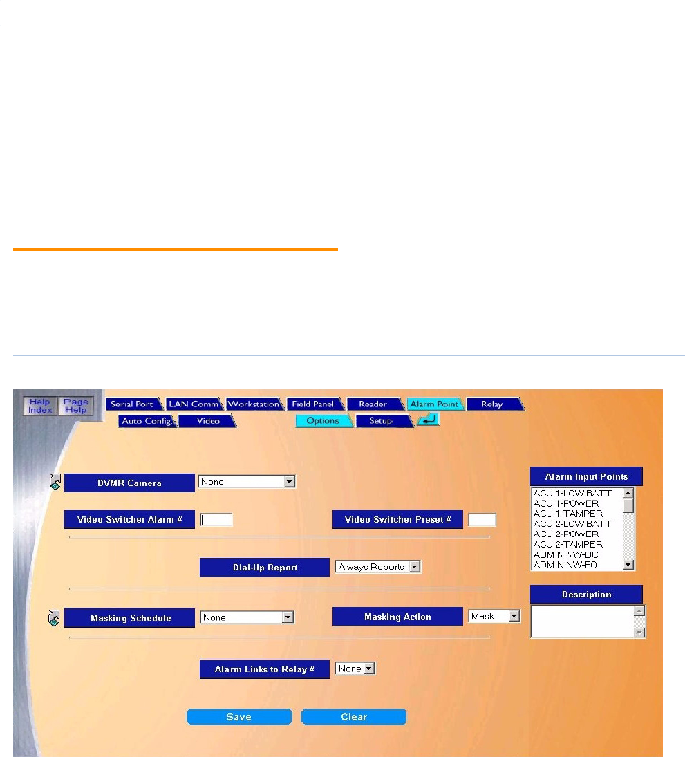
Topa z
User Manual
248
2. Wait for the Alarm Point configuration information to be displayed in the main window and the
Alarm Point description to be displayed in the “Description” window below the “Alarm Input
Points” window.
3. After making sure that the correct Alarm Point to delete is selected, click Delete.
4. A message “Are you sure you want to delete this record?” displays. Click OK to continue. A
message “Operation Complete” displays.
Alarm Point Options Page
The Options Page is used to assign digital cameras and video switchers to an alarm, to control
automatic masking actions and to link alarms to a relay. To navigate to the Alarm Point Options
page from any Hardware page click the Alarm Point tab button in the navigation bar at the top of the
main window and then the Options tab button. The following page displays.
Figure 175.Alarm Point: Options
The options page contains the following information:
DVMR Camera This is the DVMR camera that is linked to this alarm. Select the pre-configured camera from the
drop-down list. To configure a camera, click the Video | Camera tabs at the top of the screen and
complete the page that displays. For information about configuring a camera How to add a new
video camera on page 262.
Video Switcher Alarm#
(Camera#)
If an approved optional video switcher is connected to one of the serial ports of the server, the PC
can send a signal to the video switcher to trigger one of its alarms/cameras.
Enter the alarm/camera number of the optional video switcher that is to be activated when the
alarm point becomes active.
Note: When using a GE Video Switcher use the number of the camera to be called for the
Video Switcher Alarm # field.
Chapter 9
Hardware
249
Video Switcher Preset# If an approved optional video switcher is connected to one of the serial ports of the server, the PC
can send a signal to the video switcher to trigger one of its presets.
Enter the preset number of the optional video switcher that is to be activated when the alarm point
becomes active.
Dial-up Report If this alarm point is connected to a dial-up field panel, you can specify if you want the dial-up
device to store alarms and troubles until the next scheduled download to the server or send the
information to the server as they occur.
The optional reports are:
• Always Reports - Select this option if you want the field panel to dial-up the server and report
all events immediately from this point instead of being stored in memory until the scheduled
download.
• Report Troubles - Select this option if you want troubles from this alarm point to be sent
immediately to the server instead of being stored in memory until the scheduled download.
For example, a Request To Exit alarm would report if the point when into trouble, but would
not report every time a request to exit was sent.
• Log Reports - Select this option if you want alarm and troubles from this point to be stored in
the dial-up device's memory until the scheduled download time.
Note: The video option cannot be used with a dial-up panel.
Masking Schedule If the alarm point is to be automatically masked or unmasked during a time schedule, select the
pre-configured time schedule from the drop-down list. The default is Never (will not mask by time).
Note: If the desired Time Schedule has not yet been configured, click the link arrow to the left of
Masking Schedule. Configure the desired time schedule and click Save.
Masking Action If you have selected a time schedule above, then select from the Masking Action list if the point is
to be masked or unmasked during the time schedule selected.
Choose one of the options:
• Mask – Select if you want the alarm point to be masked without restrictions during the
scheduled time. At the end of the time schedule the point unmasks.
• Unmask – Select if you want the alarm point to be unmasked without restrictions (that is, the
alarm point should be monitored) during the scheduled masking time. At the end of the time
schedule the point masks.
Alarm Links to Relay # You can select a relay number to be linked for this alarm by clicking on a relay number in the drop-
down list. This allows you to link several alarm points to a single relay. The relay must be on the
same panel as the alarm point for this to function. The relay activates whenever the alarm point is
in an active state and deactivates when the alarm resets or returns to normal.
Save After all changes have been made to the Alarm Options page, click Save. The message
“Operation Complete” displays.
Clear At any point if you wish to clear out all entered information, click Clear.
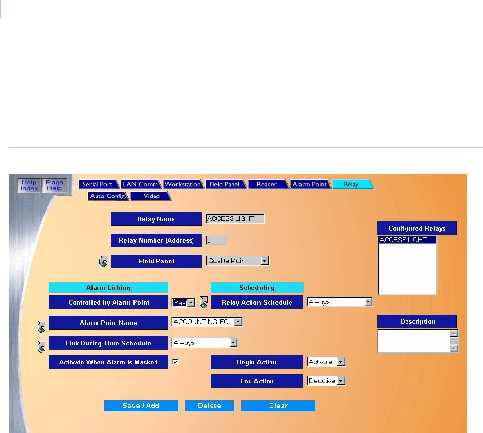
Topa z
User Manual
250
Relay Page
The Relay page allows you to add a new relay, or modify or delete an existing one.
To navigate the Relay page from any Hardware page, click the Relay tab button navigation bar at the
top of the screen, or from the main Hardware screen click the Relay Output button on the right side
of the screen. The following page displays.
Figure 176.Relay.
The Relay page contains the following information:
Relay Name Enter a name of up to 16 alphanumeric characters for the Relay Name. The name of each
relay must be unique.
Relay Number (Address) Enter the Relay Number (Address) of the relay that is being configured.
Field Panel Select from the drop-down list of pre-configured Field Panels the one to which the relay is
connected.
Alarm Linking Alarm Linking allows you to link the selected Relay to a selected Alarm Point. Any time the
alarm point goes into alarm the relay activates and when the alarm cancels the relay
deactivates. This allows you to link any number of relays to the same alarm point.
Controlled by Alarm Point If the Relay is to be linked to an Alarm Point, select Yes from the list. The default is No.
ALarm Point Name From the drop-down list of configured Alarm Point Names, select the point that activates this
relay when it goes into alarm.
Note: To configure an Alarm Point, click the link arrow to the left and the Alarm Point setup
page opens. Configure the Alarm Point and click Save.

Chapter 9
Hardware
251
How to add a relay
1. Start by clicking Clear to clear any existing data.
2. Enter the data for the new relay in the remaining fields on the Relay page.
3. Click Save. The “Operation Complete” message displays. If “Operation Failed” is displayed,
then a required field was not entered. Enter the field and try again.
How to modify a relay
1. Start by selecting the relay to be modified by scrolling through the Configured Relays list and
clicking on the relay to select it. After the fields are filled in make sure the correct relay to
modify has been selected.
2. Make any desired changes to the Relay Setup page.
3. After all changes have been made to the Relay page, click Save/Add. The “Operation
Complete” message displays.
Link During Time Schedule If you want the Relay to activate upon the alarm during a selected Time Schedule only, then
select the Time Schedule from the drop-down list of configured Time Schedules.
Note: To configure a Time Schedule, click the link arrow to the left and the time schedule
setup page opens. Configure the time schedule and click Save.
Activate When Alarm is
Masked
Under normal conditions when the Alarm Point that is linked to the relay is Masked, the relay
does not activate when the point goes into alarm. If you wish the Relay to Activate even if the
Alarm Point is Masked, click the box to the right placing a check mark in it.
Scheduling If the Relay is going to be activated or deactivated by a Time Schedule the following fields
need to be configured.
Relay Action Schedule If the relay is to be automatically Activated during a Time Schedule then select from the drop-
down list a pre-configured Time Schedules for the relay action to Begin and End.
Note: To configure a Relay Action Schedule, click the link arrow to the left and the Time
Schedule configuration page opens. Configure the panel and click Save.
Begin Action Select if the relay is to Activate or Deactivate at the beginning of the time schedule.
End Action Select if the relay is to Activate or Deactivate at the end of the time schedule.
Description Enter up to 127 characters for the Description for the relay.
Save/Add After all changes have been made to the Relay page, click Save/Add.
One of the following messages displays:
• If “Operation Complete” is displayed, no further changes are needed.
• If “Duplicate Record” is displayed, then the Relay Name has been repeated. Enter a new
name and try again.
• If “Operation Failed” is displayed, then a required field was not entered. Enter the field and
try again.
Clear At any point if you wish to clear out all entered information, click Clear
CAUTION: Clicking Clear before clicking Save deletes newly entered data.
Topa z
User Manual
252
How to delete a relay
1. To delete a relay from the system you must first select the relay to be deleted. Do this by
clicking on the name of the relay in the Configured Relays list.
2. After making sure the correct relay to be deleted has been selected (highlighted), click
Delete.
3. A message “Are you sure you want to delete this record?” displays. Click OK to continue. A
message “Operation Complete” displays.
Auto Configuration Setup Page
Auto Configuration allows you to have the system automatically configure any device by clicking
the Auto Configuration button. The system software detects any newly added device such as ACU
panel or card reader and sets it up with default values.
Default Device Names
After Auto Configuration has been completed, the devices have numeric names, for
example, Reader 2-1-3 is Host Port two (2), Field Panel address one (1), Reader number
three (3). You may want to rename the devices with your own descriptive names. For more
detailed information see the chart below.
Note: When assigning default names for IP addresses for ACU panels, the system uses descending order, starting at
250, such as: 250, 249, 248.
When you click the Auto Configuration button, the message “Please be patient while we examine
your system” displays.
Click OK to continue.
If no new devices are detected the following page displays.
Example Type COM# ACU Polling # Reader/Alarm # Alarm Type
Field Panel Device 1-0 / 250-0 Device 1 0
Reader RDR 1-0-0 / 250-0-0 RDR 1 0 0
Reader Alarm RDR 1-0-0 FO / 250-0-0 FO RDR 1 0 0 FO (Forced Open)
Alarm Alarm 1-0-0 / 250-0-0 Alarm 1 0 0
Area Area 1-0-0 / 250-0-0 Area 1 0 0
Example Type COM# ACU Polling # Reader/Alarm # Alarm Type
Panel Alarms ACU 1-TAMPER ACU 1 1 TAMPER
Input Module RIM 1-1-7-OL RIM 1 1 7 OL (Offline)
Output Module RRM 1-1-5-OL RRM 1 1 5 OL (Offline)
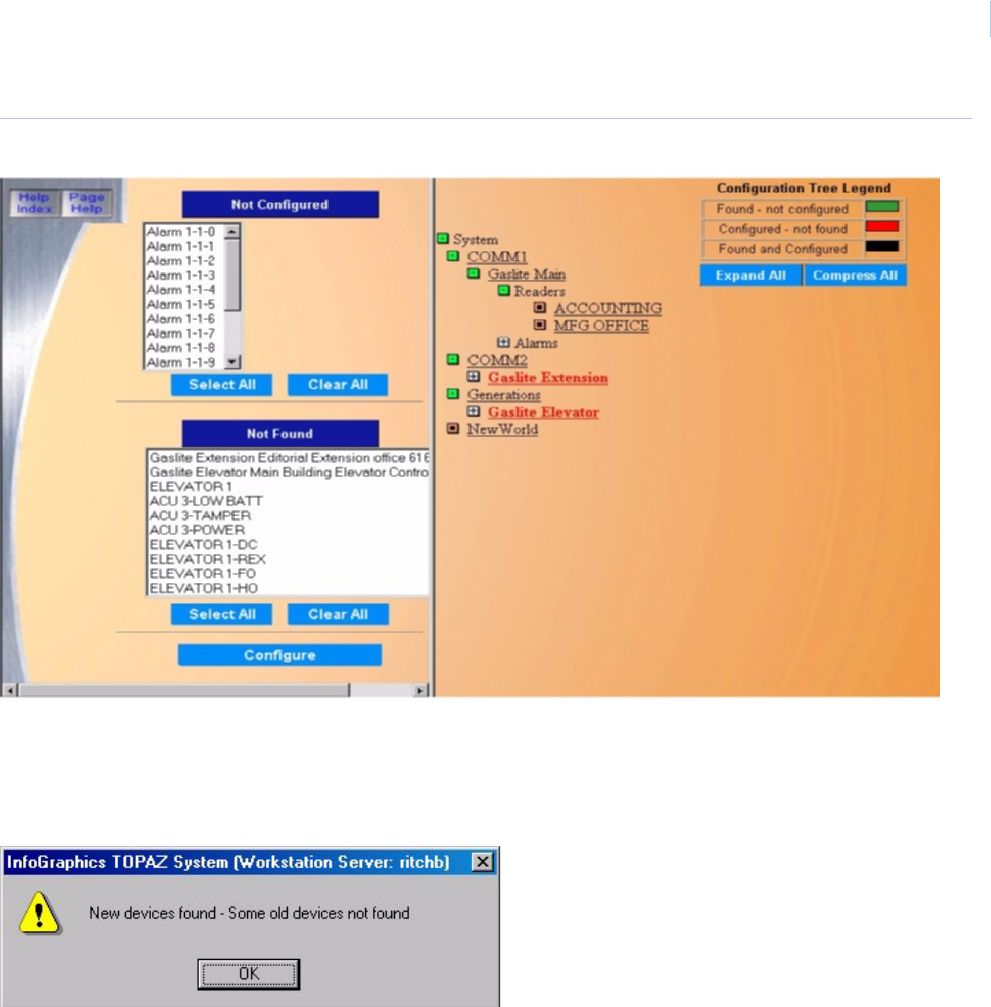
Chapter 9
Hardware
253
Figure 177.Auto Configuration Setup
You can instead select the standalone Device Tree at any time by clicking the Device Tree button on
the Main tool bar on the left side of the screen.
If new devices are detected and/or old devices are not found, a message such as the following
displays:
Left Side of the Page The page is divided into two halves with a vertical line. On the left side are two lists showing the
devices, which need your attention: those Found and Not Configured and those Configured and
Not Found.
Found and Not Configured On the left side, under Not Configured, a list of devices displays that the system found which
you have not configured yet. These devices should be configured before proceeding.
To do this, click all devices you wish to have auto configured, and then click Configure. Those
highlighted devices should no longer appear in that list, and should now be located in the
system device tree on the right side of the page, along with all Topaz devices connected to that
communication port. Any selected device may be deselected by clicking Clear.
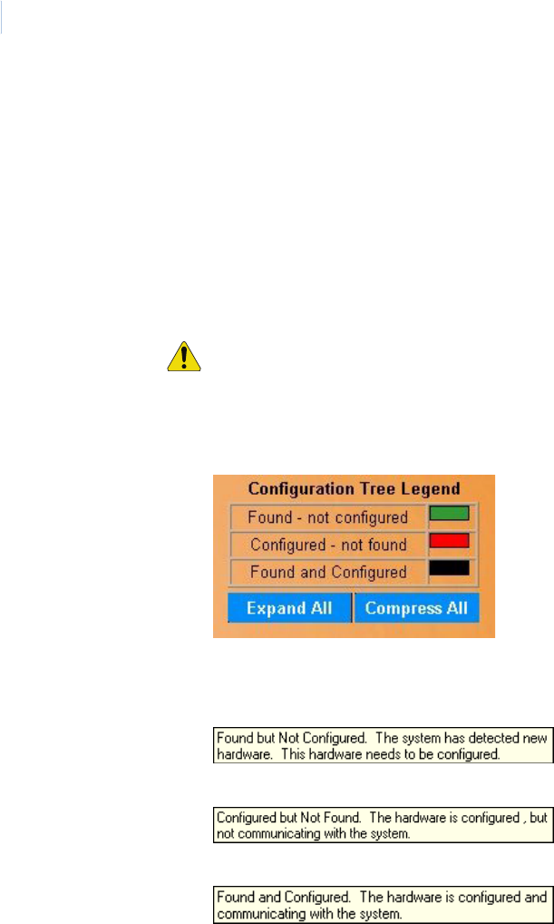
Topa z
User Manual
254
Configured Not Found On the left side, under Not Found, a list of devices displays that the system has a configuration
for but cannot find. Confirm that these devices are no longer installed and physically connected
to the server. It is possible that the device has a communication or other related problem.
If you want any device in this list removed from the database, click it to be highlighted, and then
click Configure.
Note: If you configure a Com port for one device and later unplug it and plug in another
device of a different type, when you run Hardware\Auto Configuration, Auto
Configuration will not find that device. You must reconfigure the device for that Com
port.
CAUTION: If a Com Port is not listed correctly, Auto Configuration won’t find anything under
that Com port.
Right Side of the Page
Color Legend The corner of the screen displays the color legend, which describes devices listed under the
System icon. These colors provide information about the configuration status of each device.
You can view text boxes describing the meaning of each color by placing your mouse pointer on
a color bar.
Devices shown in green are Found But Not Configured:
Devices shown in red are Configured But Not Found:
Devices shown in black are Found and Configured:
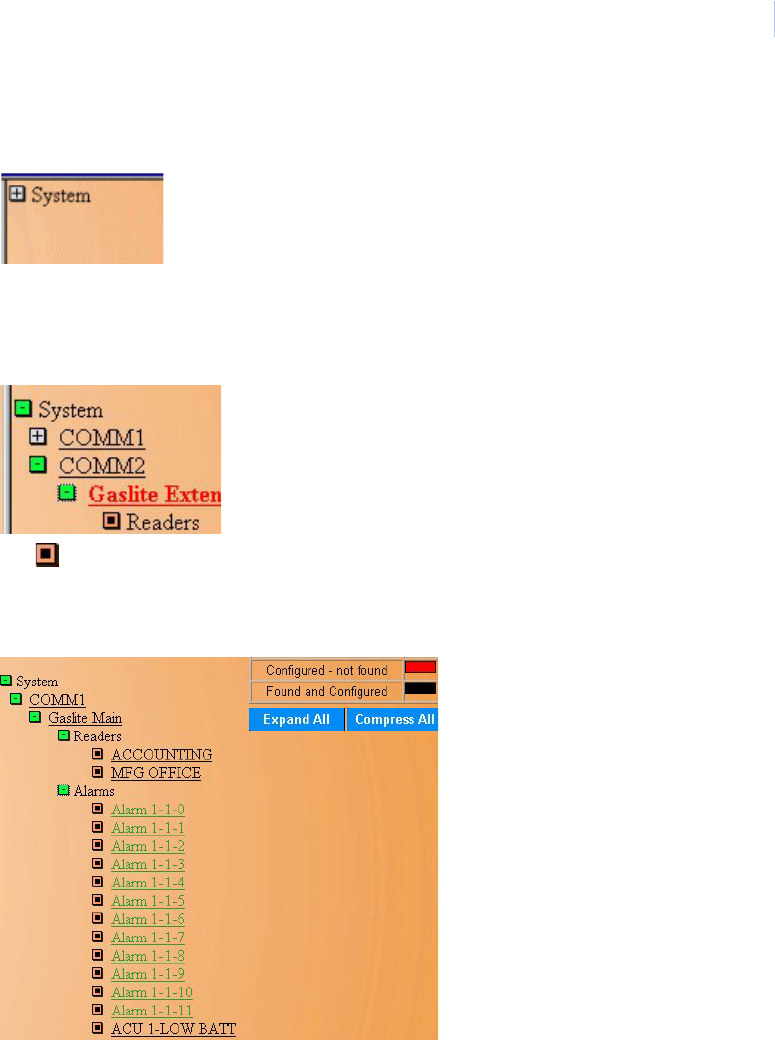
Chapter 9
Hardware
255
Device Tree You can access the Device Tree by clicking on the plus button by System at the top right side of
the page.
You can also expand the entire tree by clicking Expand All or you can compress the tree by
clicking Compress All.
Clicking this button opens the tree to show the Communications ports and LAN Adapters (ACUs
communicating over the LAN) configured on the system as shown below.
The ICON by Readers indicates that no additional information resides under that part of the
tree.
Opening more of the tree would look something like the image below.
When you leave the Auto Configuration (Device Tree) page and later return, the Tree appears
opened to the same place as it was when you left.
At anytime you can click any one of the underlined names to bring up its appropriate
configuration page and re-configure or edit that item.
For example, if the ”ACCOUNTING-FO” alarm in the tree above were clicked on it would bring
up the Alarm Point configuration page as an additional browser page with Auto Configuration
remaining in the background as shown below.
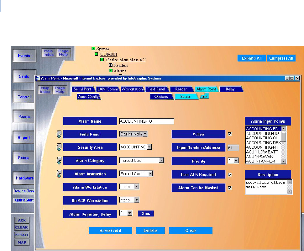
Topa z
User Manual
256
You can then make any modifications or deletions. After making changes click Save/Add.
The device tree is automatically updated with the changes you made.
When you navigate to another page, the Device Tree remains in the view you left it.
Note:
• You cannot use the Auto Configuration or standalone Device Tree to add new devices. You
must add them by using the hardware page for the device you wish to add.
• At any time, while on any other page of the Topaz system you can click Device Tree located
in the main tool bar on the left side of the screen to access the standalone device tree
page.
Chapter 9
Hardware
257
Device Tree
If you click Device Tree button, the following page displays.
Figure 178.Device Tree
To run Auto Configure, you must click the Hardware button on the main tool bar on the left and then
click the Auto Configurations button. The device tree is also displayed on the Auto Configuration
page.
Aside from auto configuring your system, and specifically for day-to-day system hardware navigation
and editing, we recommend using the Device Tree.
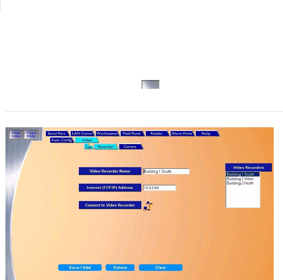
Topa z
User Manual
258
Video Recorder
Topaz supports alarm video recording. This allows the system to link the video recorded during an
alarm event to the alarm record. A digital video recorder allows the video clip to begin before the
alarm event allowing the event to be seen by the operator.
To navigate to the Video Recorder page, click the Hardware button on the main navigation bar at
the left side of the browser window then click the button next to Video on the main Hardware
page. You can also click the Video tab at the top of the window from any Hardware page. The
following page displays.
Figure 179.Video: Recorder
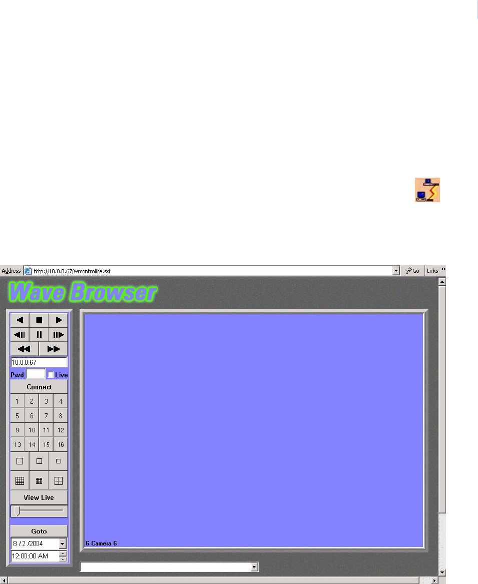
Chapter 9
Hardware
259
The Video Recorder page contains the following information:
Video Recorder Name The Video Recorder Name field assigns a name to the recorder that can then be selected
on various pages of the Topaz system. This name must be unique and clearly identify the
recorder. It could reference the location of the cameras that it controls. For example:
Administration South or Building 1 West
Internet (TCP/IP) Address The Internet (TCP/IP) Address field is used to connect the recorder to the LAN and to the
Topaz system. The address must be a static IP. IP addresses should be issued by your IT
department and configured on the recorder before completing this form.
Save/Add Click Save/Add to save the configuration to the database.
Connect to Video Recorder
Once you have saved the configuration, click the Connect to Video Recorder
button to verify that the correct recorder has been configured.
This button launches the Wave Browser. This browser allows the user to connect to a
video recorder and test the various cameras by viewing live feed from that camera
For information about how to use the Wave Browser, refer to the documentation that
came with your DVMRe

Topa z
User Manual
260
How to add a new video recorder
Before configuring the recorders in the Topaz system, they should be installed and functioning
properly. Make certain that you have the TCP/IP address which has been assigned to the recorder
available before you start the setup process.
Note: While many Digital Recorders may use DHCP addressing, Topaz must use Static IP addresses. Be certain when
installing the recorder that a static IP address is assigned to it.
1. Start by clicking Clear to clear any existing data.
2. Enter the data for the new video recorder on the Video Recorder page.
3. Click Save to save the data to the database. The “Operation Complete” message displays. If
“Operation Failed” is displayed, then a required field was not entered. Enter the field and try
again.
How to modify a video recorder
1. Start by selecting the recorder to be modified by scrolling through the Video Recorders list
and clicking on the recorder to select it. After the fields are filled in make sure the correct
recorder to modify has been selected.
2. Make any desired changes to the Video Recorder page.
3. After all changes have been made, click Save/Add. The “Operation Complete” message
displays.
How to delete a video recorder
1. To delete a video recorder from the system you must first select the recorder to be deleted.
Do this by clicking on the name of the recorder in the Video Recorders list.
2. After making sure the correct recorder to be deleted has been selected (highlighted), click
Delete.
3. A message “Are you sure you want to delete this record?” displays. Click OK to continue.
A message “Operation Complete” displays.
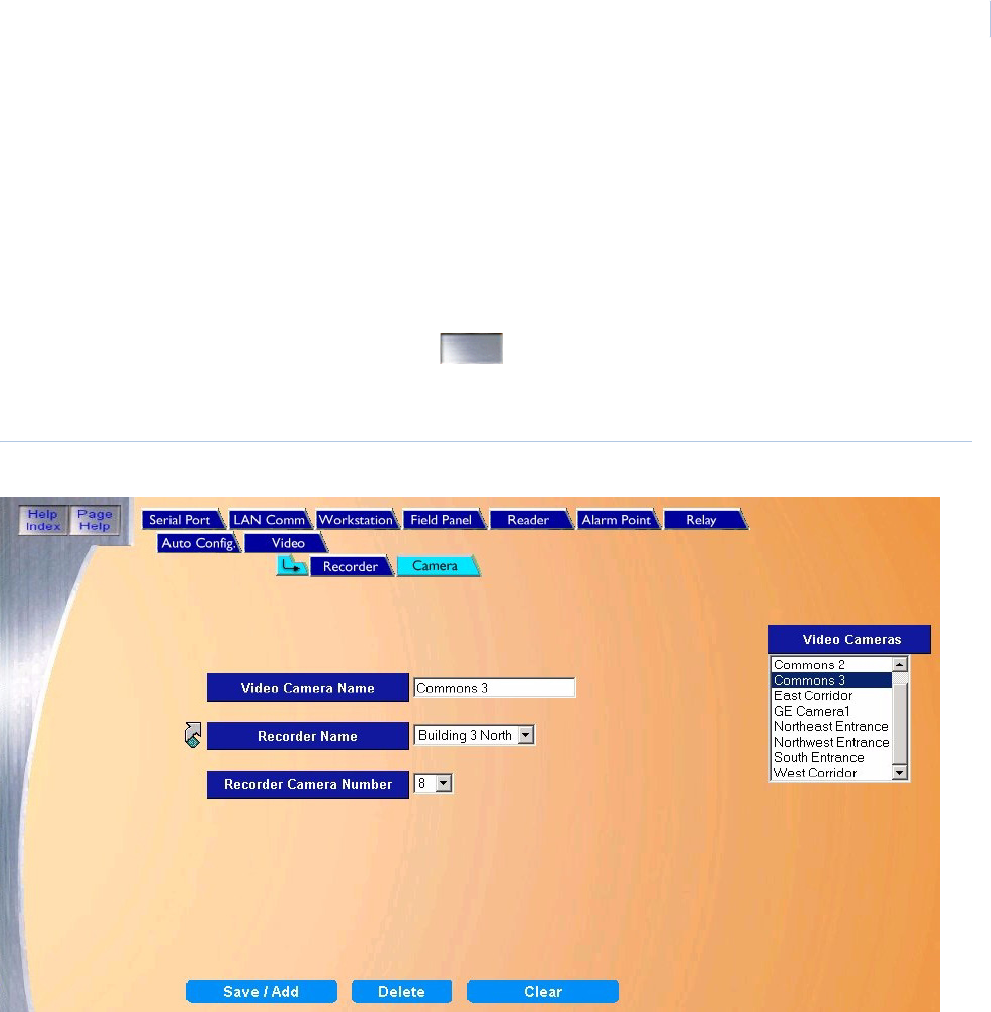
Chapter 9
Hardware
261
Video Camera
This page allows the user to link the video recorder to the cameras which monitor and record the
alarm events. Digital video recording allows the video clip to begin before the alarm event. This
feature allows the event to be seen by the operator. Pre event, Length and Quality settings are done
on the DVMRe directly. Refer to the documentation which came with your video recorder. On this
page, you assign a name to the camera and link it to a Video Recorder.
To navigate to the Video Camera page, click the Hardware button on the main navigation bar at the
left side of the browser window then click the button next to Video on the main Hardware
page then click the Camera tab. You can also click the Video tab at the top of the window from any
Hardware page and then click the Camera tab. The following page displays.
Figure 180.Video: Camera
The Video Camera page contains the following information:
Video Camera Name The Video Camera Name field is used to assign a name to the camera that can then be
selected on various pages of the Topaz program. This name must be unique and clearly
identify the camera. It could reference the area which is monitored by the camera that is being
configured. for example: Southeast corridor or Accounting Lobby, etc.
Recorder Name The Recorder Name field is used to indicate the video recorder that controls the camera.
Select the name of the recorder from the drop-down list of available video recorders.
If the correct recorder is not configured, click the link arrow to open the Video Recorder page
and configure the required recorder.
Recorder Camera Number The Recorder Camera Number field indicates the Camera Number that was assigned to this
camera on the recorder. For information regarding the assigning of Camera Numbers refer to
the documentation which came with the Video Recorder.
Save/Add Click Save/Add to save the configuration to the database.

Topa z
User Manual
262
How to add a new video camera
Use the following steps to add a new video camera to the system. Before configuring the cameras,
they should be installed and functioning properly. Make certain that you have the Recorder Name to
which the camera is attached and the number assigned to the camera on that recorder before you
start the setup process.
1. Start by clicking Clear to clear any existing data.
2. Enter the data for the new video camera on the Video Camera page.
3. Click Save to save the data to the database. The “Operation Complete” message displays. If
“Operation Failed” is displayed, then a required field was not entered. Enter the field and try
again.
How to modify a video camera
1. Start by selecting the camera to be modified by scrolling through the Video Cameras list and
clicking on the camera to select it. After the fields are filled in make sure the correct camera to
modify has been selected.
2. Make any desired changes to the Video Camera page.
3. After all changes have been made, click Save/Add to save the changes to the server
database. The “Operation Complete” message displays.
How to delete a video camera
1. To delete a video camera from the system you must first select the camera to be deleted. Do
this by clicking on the name of the camera in the Video Cameras list.
2. After making sure the correct camera to be deleted has been selected (highlighted), click
Delete.
3. A message “Are you sure you want to delete this record?” displays. Click OK to continue.
A message “Operation Complete” displays.

Chapter 9
Hardware
263

Topa z
User Manual
264

Chapter 9
Hardware
265

Topa z
User Manual
266

This chapter includes information on how to design badges.
In this chapter:
Overview. . . . . . . . . . . . . . . . . . . . . . . . . . . . . . . . . . . . . . . . . . 268
Accessing Badge Design . . . . . . . . . . . . . . . . . . . . . . . . . . . . . 270
Entering Information . . . . . . . . . . . . . . . . . . . . . . . . . . . . . . . . . 271
Editing Facilities . . . . . . . . . . . . . . . . . . . . . . . . . . . . . . . . . . . . 283
File Menu . . . . . . . . . . . . . . . . . . . . . . . . . . . . . . . . . . . . . . . . . 287
Options Menu . . . . . . . . . . . . . . . . . . . . . . . . . . . . . . . . . . . . . . 288
Chapter 10 Badge Design
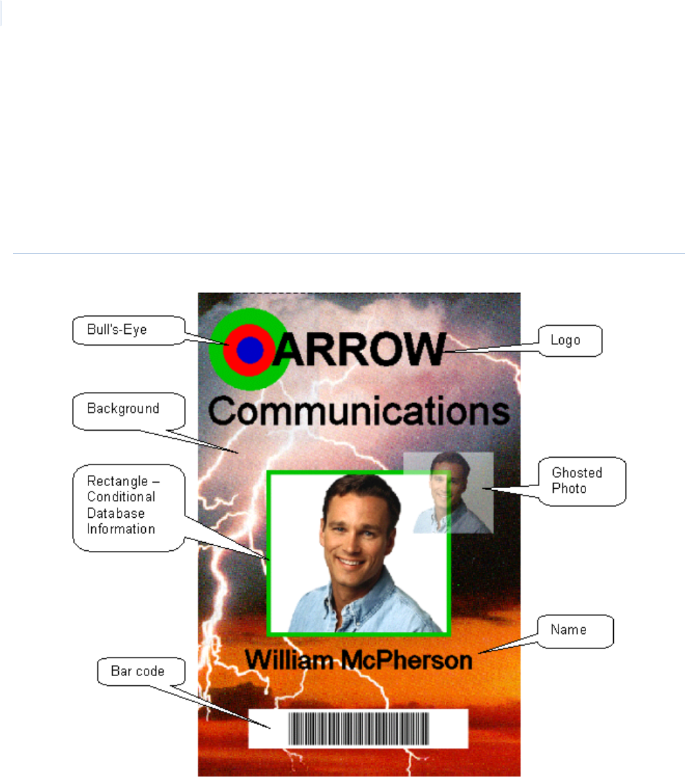
Topa z
User Manual
268
Overview
This feature is currently not being evaluated by UL.
The Badge Design page allows you to design badges for use with individual employees in the
Cardholder record.
The Topaz badge design facility is easy to use and has a wide range of features for designs. As a
demonstration, the badge shown below uses a few of the design features. This badge was designed
and saved into the system in approximately five minutes.
Figure 181.Sample badge
You can orient the design for portrait or landscape badges. You have flexibility in designing a badge.
The following features may be incorporated into a badge template. The template is then used to print
cardholder badges.

Chapter 10
Badge Design
269
A badge design can contain the following information:
Cardholder Photo The Cardholder’s photo is stored in the Cardholder record and is automatically accessed
when the Display Badge, Print Badge, or Display Photo selections are made. The photo
can be implemented with several different format selections including Chroma Key, Chroma
Cut, Ghosting, Black and White format, and Rescaling.
Cardholder Signature The Cardholder’s signature is also stored in the cardholder record and is acquired from an
optional signature panel attached to any enrollment workstation within the system.
Note: An optional signature capture pad is required for this feature.
Logos These are bitmaps of any object or scene that can be imported into the system from any
external software package. They can be used as backgrounds or as smaller symbols, and
can be overlaid on top of each other.
Rectangles, Triangles, Circles,
Ellipses
You can draw and automatically size rectangles, triangles, circles, and ellipses. You can fill
them with color from the extensive color palette within the system, or you can leave them
without a fill. You can round the corner, mix the width of the external lines, and select the
color.
Lines You can draw lines with varying styles, thickness, and color in any direction.
Fixed (Constant) Text You can enter text onto the badge at any selected location and select the font from the
extensive font list.
Database (Variable) Text You can automatically add text from the Cardholder Database. You can select the location
and orientation, and you can also define the font and whether full or partial rending of the
data shall be used. The fonts size automatically and you can choose the color for the text
from the built-in color palette.
Bar Codes You can print the card number and employee number on the badge as a bar code. You can
select the location, size, and color of the bar code.
Note: During the process of badge design, we recommend that you periodically save the
badge template using the File menu on the Menu Bar at the top of the screen. The
first time a template is saved, you must select a unique name for the template.
The name can be up to eight (8) characters in length. Use the Save As command
the first time.
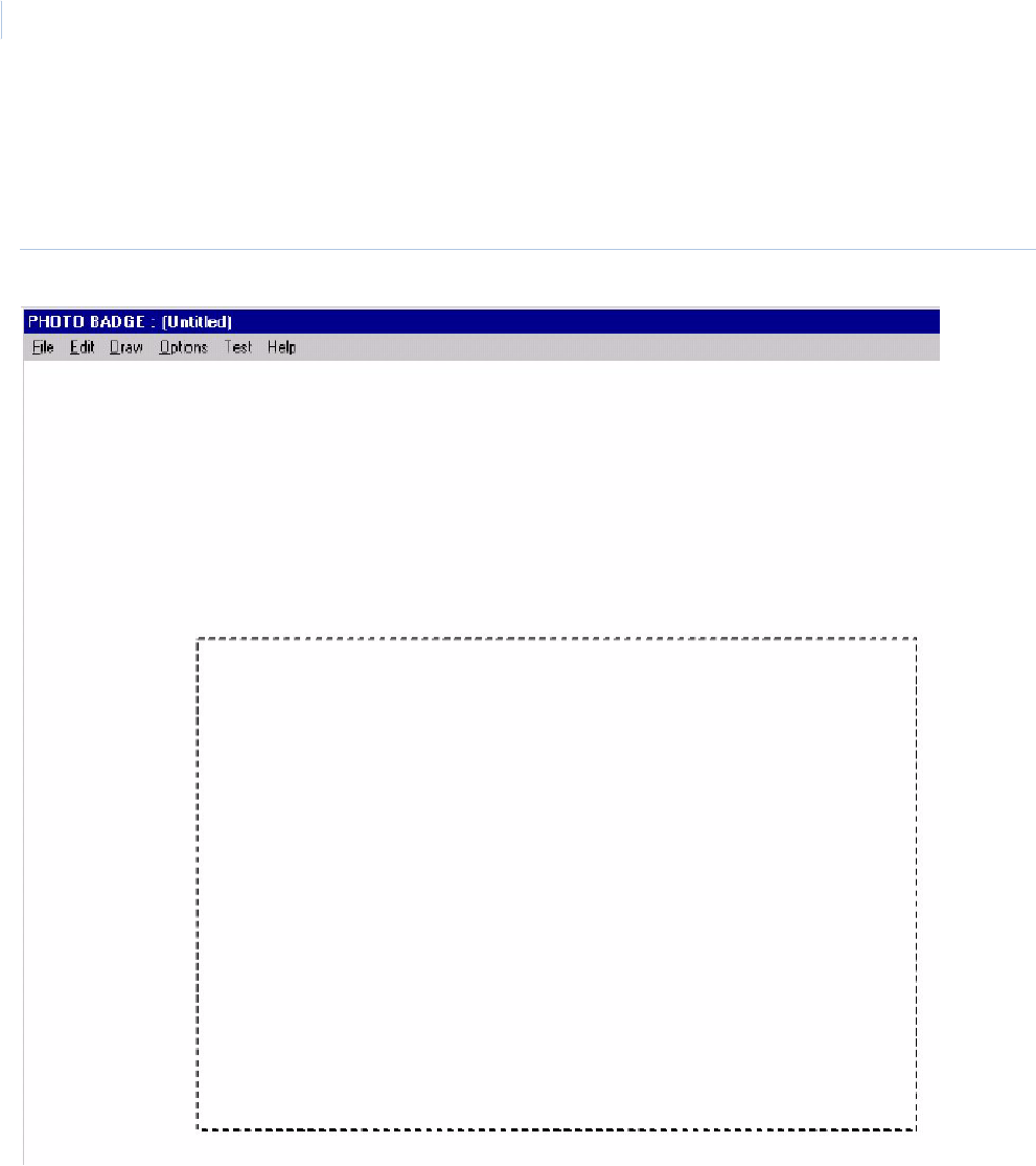
Topa z
User Manual
270
Accessing Badge Design
To navigate to Badge Design click the Photo ID button, then the Design Badge button. The system
opens the badge template design window as shown below.
Figure 182.Photo Badge template design window
Note: If the Photo Badge window does not display, make sure the workstation has been set up for Photo Badging.
To select a Portrait badge or a Landscape badge, move the mouse pointer to the Options selection
on the menu bar at the top of the window and click the left mouse button. Choose the selection of
Portrait or Landscape, which is suitable for the badge design you wish to implement. This alters the
dotted line template on the screen for badge orientation selected from the menu as shown below.
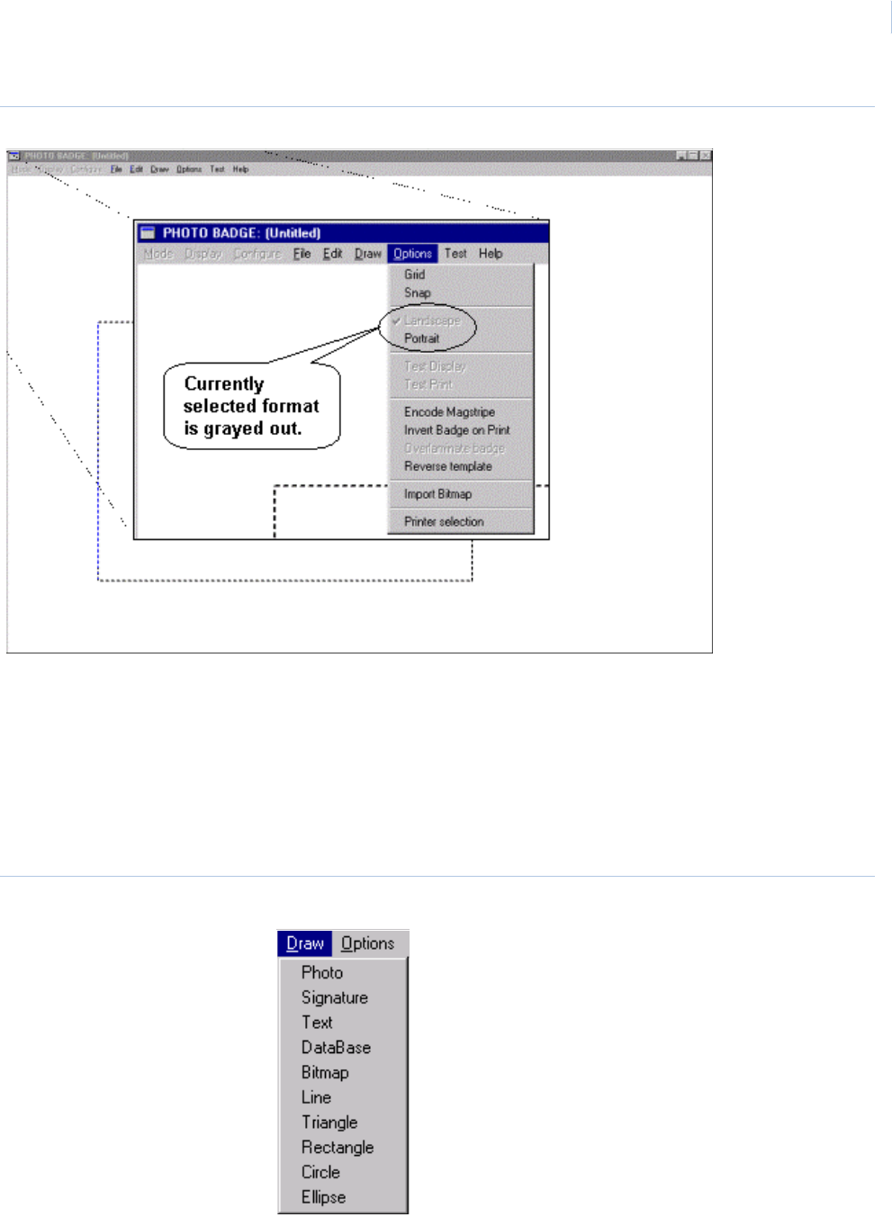
Chapter 10
Badge Design
271
Figure 183.Photo Badge Options menu.
Entering Information
To place any field information on a badge, you need to first select Draw from the menu bar at the top
of the window. This pulls down a menu list, which lists all items which may be inserted into a badge
template.
The Draw menu offers the following items:
Figure 184.Draw menu
•Photo
•Signature
•Text
• Database
•Bitmap
•Line
• Triangle
•Rectangle
• Circle
• Ellipse
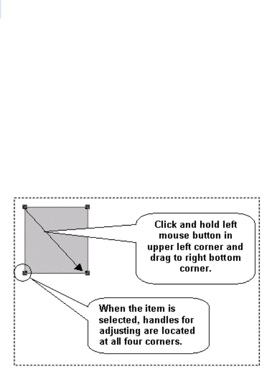
Topa z
User Manual
272
Photo and Signature
These two commands allow you to specify the position, shape, and size of the cardholder’s
photograph or signature.
Once you have selected either of theses items, the menu disappears. You should then select the
position of this item on the badge. To select the position, place the mouse pointer at the top left hand
corner of the desired position, press down and hold the left mouse button and drag it to the bottom
right hand corner of the desired position.
The screen shows a rectangle with large square dot corners called “Handles”. These “Handles”
indicate that the object has been “Picked” for editing. The rectangle has a gray background.
You can move the rectangle around on the template by placing the mouse pointer inside the selected
field (showing the handles), then hold the left mouse button down and drag the rectangle to the new
position. To change the size, place the mouse pointer directly on one of the handles, then click and
hold the left mouse button and drag to the new shape.
To select attributes, while the “Handles” are still in place, and with the mouse pointer located within
the area of the “Handles”, click the right mouse button. The Attributes screen is shown below.
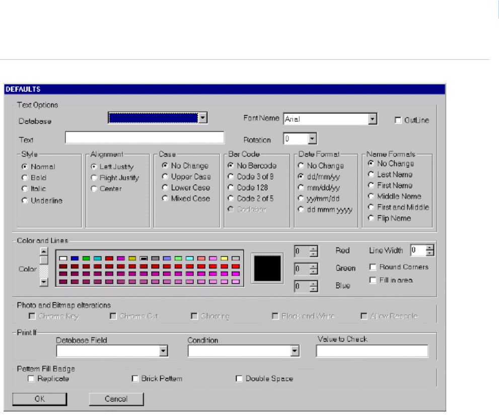
Chapter 10
Badge Design
273
Figure 185.Attributes screen
These attributes, which may be selected or changed for any particular “Picked” object, are in bold on
the screen and the attributes, which may not be used, are grayed out. In the case of the Photograph
and Signature objects, the available attributes are Chroma Key, Chroma Cut, Ghosting, Black &
White, and Allow Rescale. These are explained in detail later in this chapter.
Text and Database
These two commands allow you to specify the position, shape, and size of the text and database
field information to be shown on the badge. Text refers to “Constant” text that is entered by the
badge designer and always appears on the badge in the same form. Database refers to “Variable”
information, which is extracted from the cardholder database and is specific to the individual
cardholder
Once you have selected either of theses items, the menu disappears. You should then select the
position for these items on the badge. To select the position, place the mouse pointer at the top left
hand corner of the desired position, press down and hold the left mouse button and drag it to the
bottom right hand corner of the desired position. The screen shows a rectangle with large square dot
corners called “Handles”. These “Handles” indicate that the object has been “Picked” for editing.
A dialog window appears on the screen.
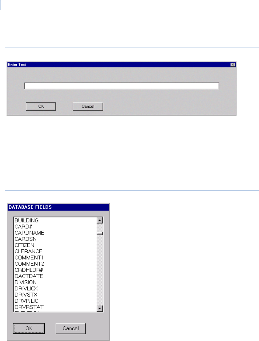
Topa z
User Manual
274
If the Text command has been selected, the dialog box provides an open field into which you can
enter the text to be placed on the badge in that position.
Figure 186.Enter Text
Once you click the left mouse button on OK, the text appears in the area between the “Handles” of
the “Picked” object.
If the Database command has been selected, a dialog box appears with a pick list, showing all
available Cardholder Database information fields that can be selected. You can scroll through all
available selections by placing the mouse pointer over the up or down arrows located at the right
hand side of the dialog box. To select a database item, you move the mouse pointer to that selection
and click the left mouse button. To enter this database item onto the badge, you may double-click the
left mouse button, or place the mouse pointer over OK, and click the left mouse button. The selected
database item appears in the area between the “Handles” of the “Picked” object.
Figure 187.Database Fields
To assign attributes to the “Picked” item, place the mouse pointer over the area between the
“Handles” and click the right mouse button. The Attributes screen appears as shown below.
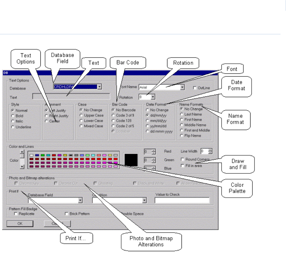
Chapter 10
Badge Design
275
Figure 188.Attributes screen
The Font Size is determined by the size of the rectangle drawn on the template. To adjust the size of
the font, try changing the height of the rectangle. Notice that the sample text in the rectangle
changes as you adjust the height of the rectangle.
The length of the rectangle determines how much text is shown/printed on the badge. If the text is
longer than the rectangle, it still shows when the badge is printed or displayed.
Text and Database Options
In the case of the Text and Database objects, the following attributes are available from the Text
Options section:
• Font Name • Outline
•Style •Alignment
• Case • Bar Code
• Date Format • Name Formats
• Rotation • Print If
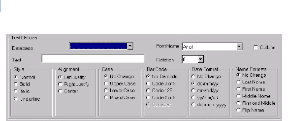
Topa z
User Manual
276
Font Name To select a font, place the mouse pointer over the down arrow on the left of the Font Name,
and click the left mouse button. A pick list appears. Use the up and down arrows at the left
of the pick list to scroll through the available fonts. To select a font, place the mouse pointer
on to the selected font and click the left mouse button. The pick list disappears, and the
selected font name shows in the field next to the Font Name legend.
Outline The Outline command allows you to select the color and font for the text, but in outline only,
with the background information visible through the text characters.
Alignment The Alignment command allows you to select whether the text is Left Justified, Right
Justified, or Centered inside the picked rectangle.
Case The Case command allows you to specify the typeface to be used for the selected Text or
Database item. The options are:
• No Change
• Upper Case
• Lower Case
• Mixed Case
Selecting No Change causes the data to be printed exactly as typed for a Text item or
exactly as entered in to the database for a Database item.
Selecting Upper Case causes the data to be printed entirely in Upper Case letters.
Selecting Lower Case causes the data to be printed entirely in Lower Case letters.
Selecting Mixed Case causes the data to be printed with the first letter of each word
Capitalized, and the other letters in lower case. If the text contains a capitalized letter within
a word (like a person’s name), the mixed case setting changes that letter to lower case. For
example, McDonald becomes Mcdonald.
Bar Codes The Bar Code command allows you to represent any numerical Text or Database
Information on the badge. The selections are:
• No Bar Code
• Code 3 of 9
• Code 128
• Code 2 of 5
Date Format The Date Format command allows you to select the format in which dates may be
represented on the badge. The available formats are:
• dd/mm/yy
•mm/dd/yy
• yy/mm/dd
• dd mmm yyyy

Chapter 10
Badge Design
277
Name Formats The Name Format command allows you to specify the format in which the Cardholder’s
name, as entered in the system Cardholder database, is printed on the card when selected
using the Database command. The options are:
• No Change
• Last Name
•First Name
• Middle Name
• First and Middle
•Flip Name
By using the No Change selection, you can choose to have the name printed in the same
format as it was entered into the system database.
The Last Name, First Name, Middle Name and First and Middle options allow you to specify
that only these parts of the Cardholders name is printed in the selected object field.
Using these selections in multiple Database fields allows you to put different parts of the
Cardholder's name at different locations on the Badge.
The Flip Name command allows you to enter the Cardholder's name into the selected field
in reverse order from that which it is entered into the Cardholder Database. For example, if
the Cardholder's name is entered into the Database as Doe John, using the Flip Name
command causes it to be printed on the card as John Doe.
Place the mouse pointer over the relevant button and click the left mouse button. A black
spot appears in the center of the button to indicate the item has been selected.
Rotation The pop up menu allows you to select a rotation of 0°, 90°, 180°, or 270°.
Color and Lines The color for the printed text on the badge is selected from the extensive color palette in the
Color and Lines section of the Attributes screen. The Lines portion of this section does not
apply to Database or Text applications and is dealt with under the sections relating to Line,
Triangle, Rectangle, Circle, and Ellipse.
The palette shows a small selection of the total colors available. To view more colors, place
the mouse pointer over one of the arrows at the left of the color palette, click the left mouse
button and hold it down until the right shade of the desired color appears. Release the left
mouse button and the scrolling stops. To select the desired shade, place the mouse pointer
over the selected color and click the left mouse button. A box appears indicating that the
color has been selected.
If none of the colors on the palette appear suitable, you may tailor a color to suit by using
the Red, Green and Blue color adjusters at the right of the color palette. You should first
select from the palette the nearest color to the desired shade. The color you selected
shows in the large color frame to the left of the color adjusters. To adjust the tint, you can
then place the mouse pointer over the up or down arrow next to the tint number of the Red,
Green or Blue color adjuster and click the left mouse button to change the value of the
selected tint. The tint values may be set between 0 and 256. As the tint is adjusted, the
actual color is shown in the large color frame at the left of the color adjusters, and also in
the selected palette color surrounded by the black box. This particular color is then saved
as part of the standard color palette for future use.
Print If- The Print If section of the attributes screen may be used to define the conditions under
which a “Picked” object is printed. Print If can be used to print text or a bitmap image,
photograph, signature, etc. only for some cardholders.
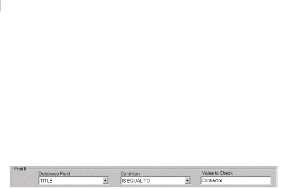
Topa z
User Manual
278
As an example, the following procedure enables you to print the word “Contractor” on the
badges for Cardholders who are contractors. To do this, you create a Print If condition of
“TITLE IS EQUAL TO CONTRACTOR”.
Place the mouse pointer over the down arrow in the Database Field of the Print If section.
Click the left mouse button and a pick list appears showing all available fields in the
Database. Scroll through the pick list by placing the mouse pointer over the down arrow
and clicking the left mouse button and holding it down until the legend “TITLE” appears in
the list. Release the left mouse button, and move the mouse pointer over the word “TITLE”,
and click the left mouse button. The pick list disappears, and the word “TITLE” appears in
the Database Field.
Move the mouse pointer to the down arrow by the side of the Condition field and click the
left mouse button. A pick list appears with arrows and a scroll bar at the side. Move the
mouse pointer to the legend “IS EQUAL TO” and click the left mouse button. The pick list
disappears, and the legend “IS EQUAL TO” appears in the Condition field.
Move the mouse pointer to the “Value to Check” field and click the left mouse button. A
cursor appears in the “Value to Check” field. Type the word CONTRACTOR into the field
The Print If command allows you to select whether a “Picked” object shall be printed on a
badge based on the following conditions compared to information contained in the
Cardholder database:
IS EQUAL TO
IS GREATER OR EQUAL TO
IS GREATER THAN
IS LESS OR EQUAL TO
IS LESS THAN
IS NOT EQUAL TO
This is very useful in designing badges that are specific to individual cardholders.
Once you have selected the various items from each of the above sections to define the
details of the “Picked” Text or Database object, you may return to the badge design screen
by placing the mouse pointer over OK at the base of the screen and clicking the left mouse
button.
The “Picked” object now appears on the screen in the format, which you have selected, still
with the “Adjustment Handles” on the rectangle. The Font size may however be unsuitable
and can be adjusted by altering the size of the “Picked” object. To do this, move the mouse
pointer over the bottom right “Adjustment Handle” of the object, press the left mouse button
and move it to the correct size for the text in the object. The Font Size automatically adjust
to fit the new size of the picked object.
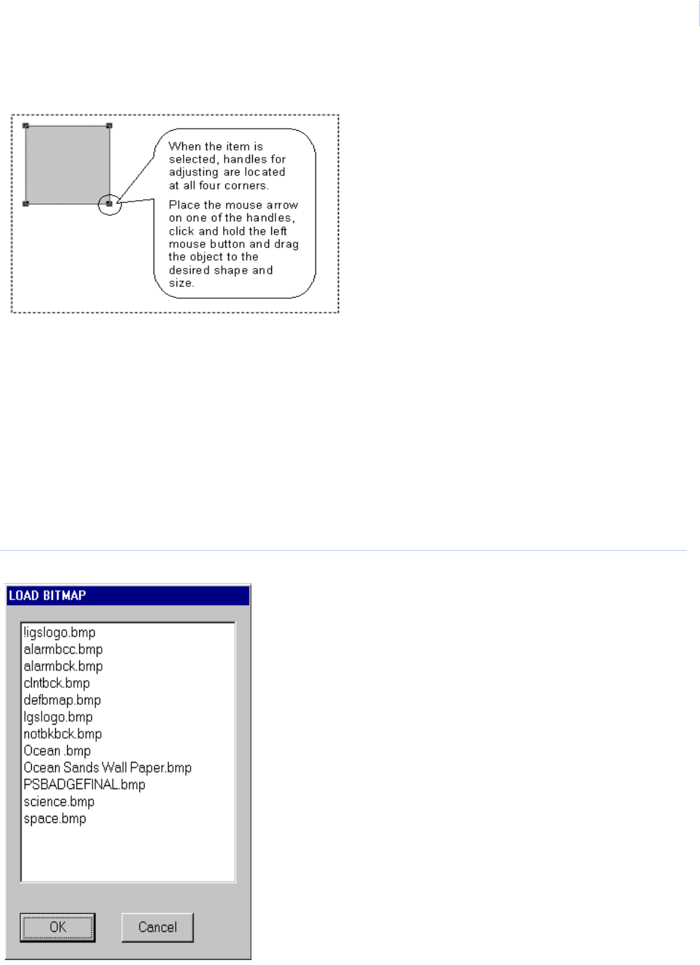
Chapter 10
Badge Design
279
Bitmap
The Bitmap command allows you to specify the placement of a bitmap logo or picture on the badge,
and to manipulate it to suit the overall badge design. For more information see Import Bitmaps on
page 290.
Once you have selected the Bitmap command from the Draw menu, the menu disappears. You
should then select the position in which this item is to be located on the badge. To select the position,
place the mouse pointer at the top left hand corner of this selected position, press down and hold the
left mouse button and drag it to the bottom right hand corner of the desired position. The screen
shows a rectangle with large square dot comers called “Handles”.
Figure 189.Load Bitmap

Topa z
User Manual
280
These “Handles” indicate that the object has been “Picked” for editing. The “Picked” rectangle
defines the position in which the desired object is placed on the badge. When you release the left
mouse button, a dialog window appears on the screen.
The dialog window shows a list of bitmaps stored in the system. Use the scroll bar at the side of the
dialog box to scan through the available bitmaps. Select the desired bitmap by moving the mouse
pointer over the bitmap name and clicking the left mouse button. This highlights the bitmap name.
Either double-click the left mouse button over the highlighted name or move the mouse pointer to OK
and click the left mouse button. The Bitmap appears in the area between the “Handles” of the
“Picked” object.
When the bitmap image is displayed in the area between the “Handles” of the Picked object, the full
image may not be displayed if the Picked object does not have the correct relative dimensions of
height and width. The Picked object may be adjusted for relative dimensions by placing the mouse
pointer over one of the “Handles” and holding down the left mouse button. This grabs the “Handle”
and allow you to resize the Picked object until the entire bitmap portion, which you require, is shown
inside the Picked object. You may then size the image by using the same method to adjust the size of
the Picked object, keeping the relative dimensions of the Picked object the same, while increasing or
decreasing its overall size.
Once the image has been correctly sized, you can move it by placing the mouse pointer over the
area of the Picked object, clicking and holding the left mouse button, and dragging the object to the
required position on the badge.
Once the bitmap image is placed, you may assign attributes to the image by placing the mouse
pointer within the area of the Picked object and clicking the right mouse button. These attributes
include Chroma Cut, Chroma Key, Ghosting, and Black and White. These are explained in more
detail later in this section on Badge Design.
The other available attribute selection is Print If command. This command operates when a
condition is placed on a specified database item. The Print If function is an extremely powerful tool
in designing badges specific to individual cardholders and is explained in more detail earlier in this
section.
Line
The line drawing tool is a way to add simple lines to the badge design. To add shapes, see Triangle,
Rectangle, Circle, & Ellipse on page 281.
Start drawing the line by placing the mouse pointer at the starting point on the badge. Click and hold
the left mouse button and move the mouse pointer to the ending point. Release the mouse button. A
light gray line appears on the badge with a black positioning box on each end. The Line can be
moved by placing the mouse over one of the positioning boxes and then click and hole the left mouse
button. Move the positioning box to the new ending point and release the mouse button.
To remove a line, select the line by clicking on the line to reveal the positioning boxes. Once the line
is selected, click the Edit menu on the main tool bar, and select Cut. The line disappears from the
badge design.

Chapter 10
Badge Design
281
Line Attributes
With the line selected (positioning boxes are visible), click the right mouse button to open the
attributes window.
The Color and Lines section allows you to select or define a color for the line, and also to define the
thickness of the lines. Select the color you want from the palette, adjust the thickness of the line and
apply the attributes by clicking OK.
More information about the Color and Lines section of the attribute window can be found in the
section Text and Database on page 273.
Triangle, Rectangle, Circle, & Ellipse
The Triangle, Rectangle, Circle, and Ellipse commands allow you to specify the placement of
these automatically drawn geometric figures into the badge, and to manipulate them to suit the
overall badge design.
By selecting any of these commands, you may position the figure on the badge by placing the mouse
pointer in the approximate location in which the figure is required, clicking and holding down the left
mouse button, and dragging the pointer from the point of origin. The figure displays on to the screen.
To resolve the triangle and ellipse to the correct dimensions, you should release the left mouse
button, and move the mouse pointer to the second “Handle” near the point of origin, depress the left
mouse button and drag the “Handle” until the triangle or ellipse resolves itself to the required
dimensions.
Once the required dimension has been obtained, you may drag the figure to a more exact position on
the badge by placing the mouse pointer over the general area of the Picked object, depressing the
left mouse button and dragging the object to the required position. Releasing the left mouse button
drops the Picked object in the selected position.
To select attributes for the picked object, you should place the mouse pointer over the general area
of the picked object and click the right mouse button. The attributes screen appears.
The Color and Lines section and the Print If sections are highlighted showing that these sections
may be used to define attributes for the badge.
The Color and Lines section allows you to select colors or define colors for the figure, and also to
define the thickness of the lines and whether or not the figure should be filled with color.
The color palette shows a small selection of the total colors available. To view more colors, place the
mouse pointer over one of the arrows at the left of the color palette click the left mouse button and
hold it down until the right shade of the desired color appears. Release the left mouse button and the
scrolling stops. To select the desired shade, place the mouse pointer over the selected color and
click the left mouse button. A box appears indicating that the color has been selected.
If none of the colors on the palette appear suitable, you may tailor a color to suit by using the Red,
Green and Blue color adjusters at the right of the color palette. You should first select from the palette
the nearest color to the desired shade. Once selected, this color is surrounded by a black square.
The color also shows in the large color frame to the left of the color adjusters.
To adjust the tint, you can place the mouse pointer over the up or down arrow next to the tint number
of the Red, Green or Blue color adjuster and click the left mouse button to change the value of the
selected tint. The tint values may be set between 0 and 256. As the tint is adjusted, the actual color
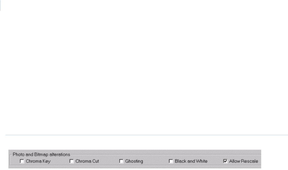
Topa z
User Manual
282
is shown in the large color frame at the left of the color adjusters, and also in the selected palette
color surrounded by the black box. This particular color is saved as part of the standard color palette
for future use.
You may select the thickness of the lines in the figure using the line width selector on the right of the
Color and Lines section. You may also select rounded comers and the ability to fill the figure with a
color selected from the color palette.
Alterations
Chroma Cut, Chroma Key, Ghosting, Black & White, and Allow Rescale
These selections allow you to adjust the color attributes of the selected bitmap, in the “Photo and
Bitmap Alterations” section of the attributes screen, as shown below.
Figure 190.Photo and Bitmap alterations
Chroma Cut and Chroma Key These allow you to remove color from an image. Chroma Cut removes the color from the
image background, whereas Chroma Key removes the color from the whole of the image.
When a Chroma function is selected, the system automatically selects the top left pixel of
the image, and the top right pixel, and removes these from the image. It is very important
therefore, for successful use of these features that the background of the image should be
a uniform color, and be uniformly lit.
By utilizing Chroma Cut on a logo, for example, the outline of the logo can be
superimposed over a background image. By using Chroma Key, the background may be
seen through various parts of the image as well as the background. However, if Chroma
Key is used, any part of the image containing the Chroma Keyed colors is also removed.
Ghosting The Ghosting facility is normally used for photographs and is designed to make the copying
of badges extremely difficult. The process removes each alternate pixel from the
photograph, giving it a slightly washed out appearance, and ensuring that any attempt to
copy the image can be easily detected.
Black & White This function converts color photographs and bitmaps into a grayscale representation.
Allow Rescale This function is useful in ensuring an image fits within the handles of a Picked Object. The
system automatically re-sizes the image to fit the size of the selected object.
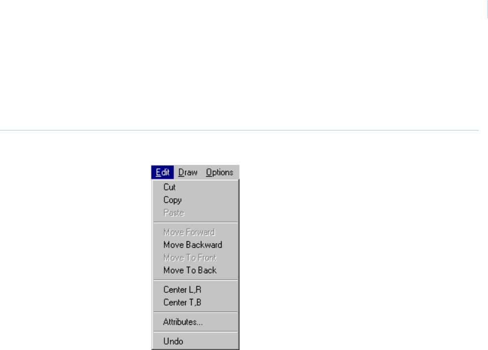
Chapter 10
Badge Design
283
Editing Facilities
Any Picked object can be edited using the Edit commands. To select the edit menu, move the mouse
pointer to Edit on the menu bar at the top of the screen and click the left mouse pointer. A menu
appears with the following items:
Figure 191.Edit menu
Cut, Copy, Paste and Undo
The Cut, Copy, Paste, and Undo facilities follows the standard convention for these functions as in
most word processing or drawing software packages.
If you are not familiar with these conventions, the Cut facility, if selected, removes any Picked object
from the badge design. The Cut object is temporarily stored in memory. If the Paste command is
selected next, the Cut object appears in the last selected position on the badge.
The Copy command operates in the same way as the Cut command, but instead of removing the
Picked object a copy is stored in memory and the object remains on the badge. If you then move the
mouse pointer to a new position on the badge and click the left mouse button, selecting the Paste
command from the Edit menu places a copy of the Picked object at the selected position. Each
subsequent use of the Paste command places a copy of the picked object on the badge until either
the Cut or Copy command is used for a different Picked object.
Deleting Items From Template
To delete an unwanted field/item from the template, select the item by clicking on it to cause the
handles to appear. Click the Edit menu and select the Cut option from the menu.
Note: The Cut option is the only way to delete an item from the template.
•Cut
•Copy
•Paste
• Move Forward
• Move Backward
• Move to Front
• Move to Back
• Center L to R
• Center T to B
• Attributes
•Undo
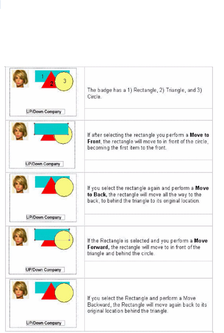
Topa z
User Manual
284
Move Forward, Move to Front, Move Backward and Move to Back
The badge may be designed to have a virtually unlimited number of layers on which objects may be
placed. The Move commands allow you to move the individual Picked object forward or backwards
through the layers, so that individual objects may be superimposed over other objects. This is often
used to ensure that counterfeiting of a badge is made more difficult.
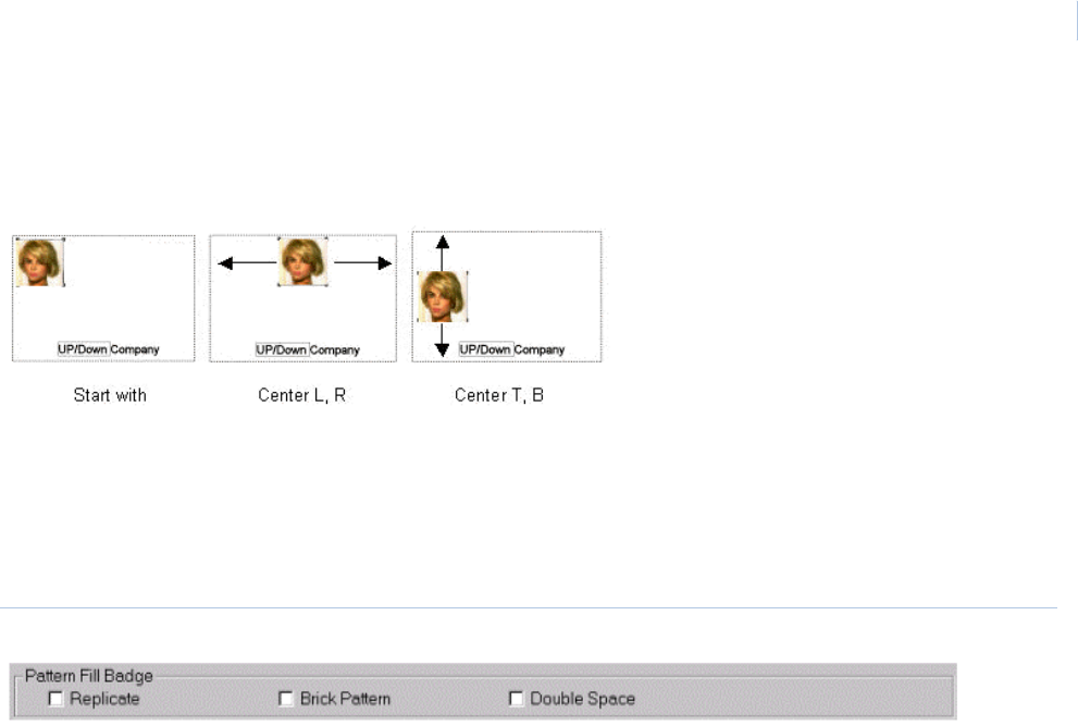
Chapter 10
Badge Design
285
Center L, R and Center T, B
Elements of the badge may need to be aligned. Alignment can be done by a click of the mouse.
Select the object first and then select Center Left to Right or Center Top to Bottom.
Pattern Fill Badge
If you want to duplicate the text or image in the background to cover the whole area of the badge,
you can select one of three options.
Figure 192.Pattern Fill Badge options
Replicate
The pattern of text or image is copied in adjacent rectangles. For example, if we use the text “Acme
Products Inc.” in a small rectangle, the background might look like this:
Acme Products Inc. Acme Products Inc.
Acme Products Inc. Acme Products Inc.
Acme Products Inc. Acme Products Inc.
Acme Products Inc. Acme Products Inc.
Brick Pattern
If you also choose the Brick Pattern, the background might look like this:
Acme Products Inc. Acme Products Inc.
ducts Inc. Acme Products Inc. Acme Pro
Acme Products Inc. Acme Products Inc.
ducts Inc. Acme Products Inc. Acme Pro
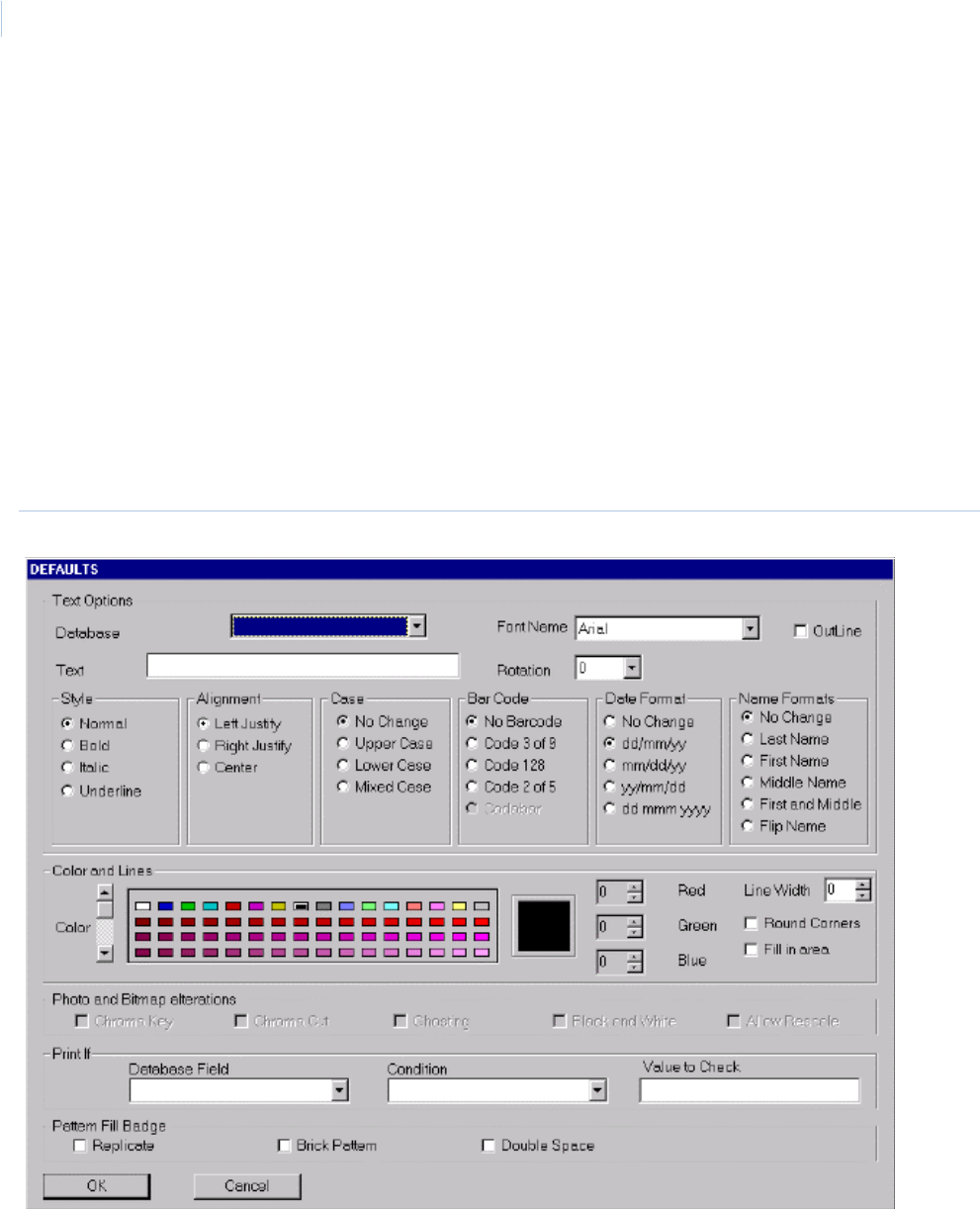
Topa z
User Manual
286
Double Space
If you also choose Double Space, the background might look like this:
Attributes
The Attributes selection is the same as clicking the right mouse on an element in the badge to have
the attributes window pop up as shown below.
Figure 193.Attributes
Acme Products Inc.
Acme Products Inc.
Acme Products Inc.
Acme Products Inc.
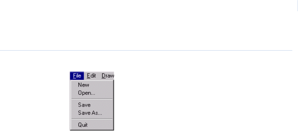
Chapter 10
Badge Design
287
File Menu
Figure 194.File menu
During the process of badge design, we recommend that you periodically save the badge template
using the File menu on the Menu Bar at the top of the screen. The first time a template is saved you
must use the Save As command.
To display the File menu, move the mouse pointer to the File menu on the menu bar at the top of the
screen and click the left mouse button. To save a template for the first time, place the mouse pointer
over the Save As command and click the left mouse button. A dialog box appears into which you can
type the name of the template being saved. The template name may be up to eight characters and
no spaces. Once you have selected OK, the system save the template using a TPL suffix.
Once you have initially saved the template using the Save As command, future modifications to the
template can be saved using the Save command from the File menu. Using the Save Command
saves the latest version of the template under its existing filename.
To modify an existing template File Menu, it is first necessary to open the file containing the template.
To do this, you should select the File menu from the menu bar at the top of the screen. Select Open
from the File menu, and then select the required template from the pick list of templates. You may
open a template file by either (1) placing the mouse pointer over the selected template name, and
double-clicking the left mouse button, or by (2) clicking once to highlight the file and then moving the
mouse pointer to OK and again clicking the left mouse button.
•New
•Open
•Save
• Save As...
•Quit
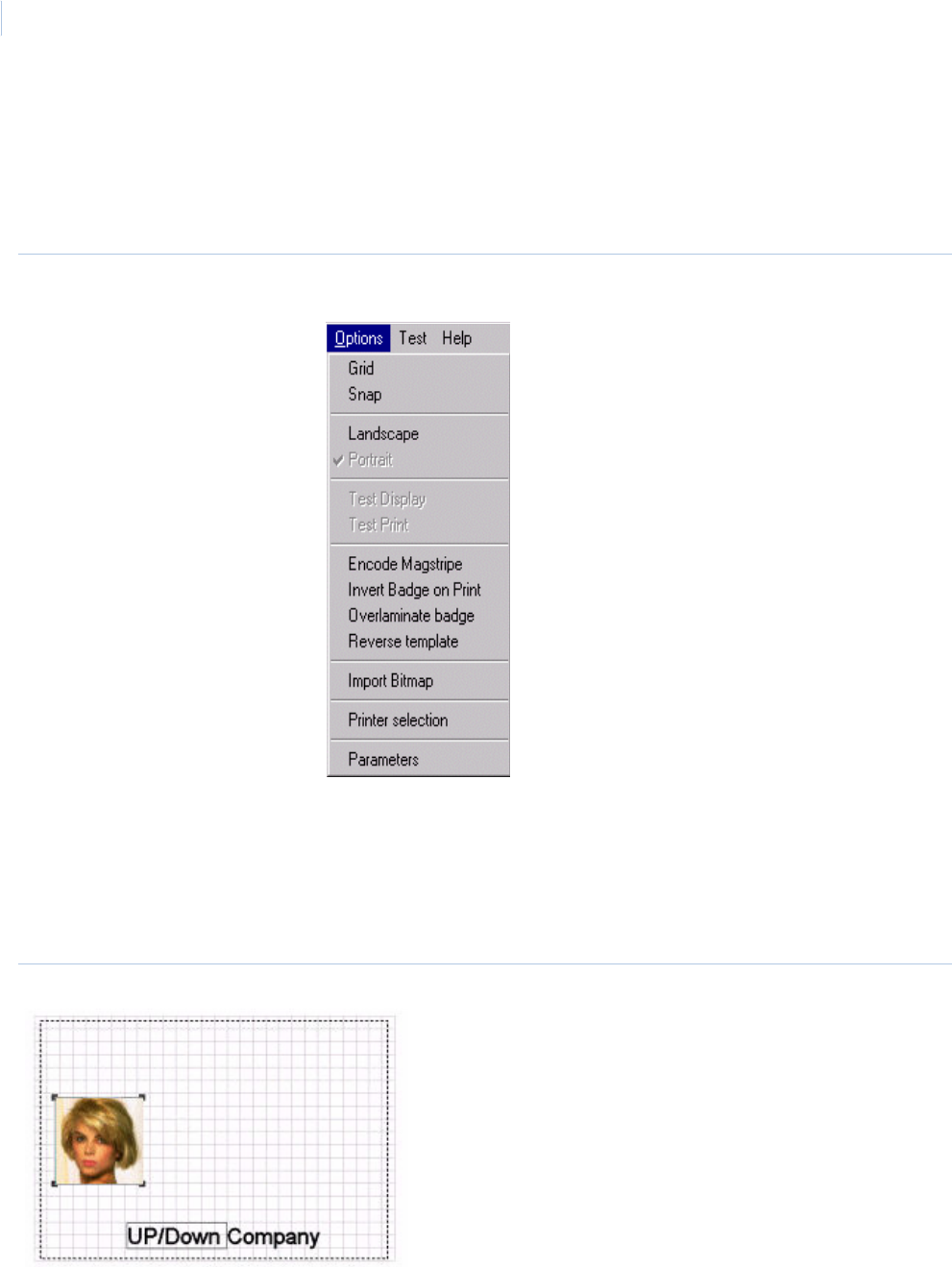
Topa z
User Manual
288
Options Menu
With the system in Badge Design Mode, you may select the Options menus by placing the mouse
pointer over the word Options on the menu bar at the top of the screen and clicking the left mouse
button. The options menu appears showing the following available selections:
Figure 195.Options menu
Grid
The Grid option provides a grid of dotted lines across the face of the badge to assist in locating
various items of the badge design. Selecting Grid a second time from the Options menu removes the
grid from the display.
Figure 196.Grid option
•Grid
•Snap
• Landscape
•Portrait
• Test Display
•Test Print
• Encode Mag Stripe
• Invert Badge on Print
• Overlaminate badge
• Reverse template
• Import Bitmap
• Print selection
• Parameters
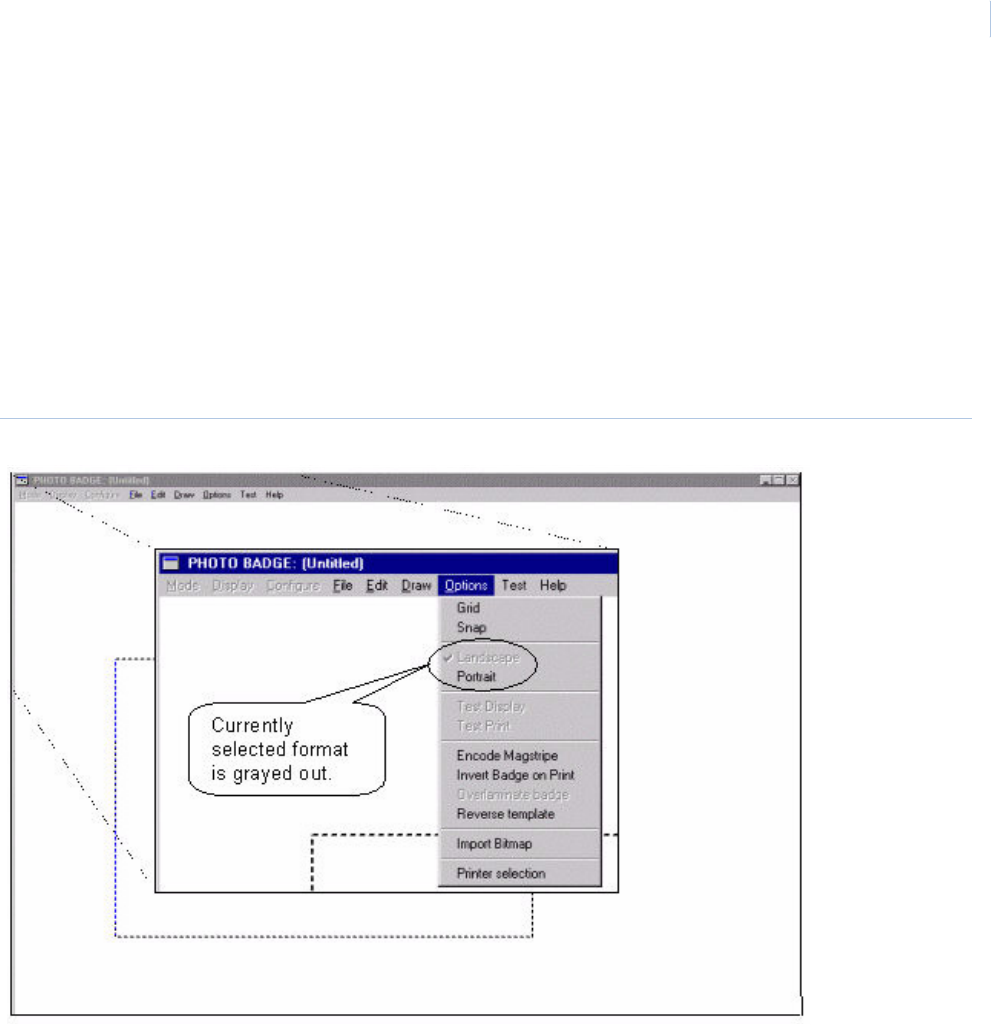
Chapter 10
Badge Design
289
Snap
The Snap facility assists you in lining up objects to the grid lines. When Snap is selected, the system
aligns the “Handles” on a picked object with the nearest grid line.
Landscape and Portrait
To select a Portrait badge or a Landscape badge, move the mouse pointer to the Options selection
on the menu bar at the top of the window and click the left mouse button. Choose the selection of
Portrait or Landscape, which is suitable for the badge design you wish to implement. This alters the
dotted line template on the screen for badge orientation selected from the menu as shown below.
Figure 197.Photo Badge Options menu
Test Display, Test Print
The Test Display command allows you to view the badge design with the database information
designed into the badge from a default cardholder file set up in the system at the time of delivery.
This gives you the opportunity to view the badge design with real database information.
Note: Not all fields are visible.
The Test Print command allows you to print the badge shown with the Test Display command.

Topa z
User Manual
290
Encode Mag Stripe
Selecting the Encode Mag Stripe command sets the printer to encode the magnetic strip on the card
with the card number in the standard GE format.
Note: This can only be done if the correct card stock is used, and an approved printer with Magnetic Stripe encoding
option is used with the system.
Invert Badge on Print
Rotates the image 180° when printing the badge.
Note: Rotation is usually required for printing Mag Stripe cards.
Overlaminate Badge
This feature laminates a security hologram on to the card during printing. The printer must support
this feature, such as Eltron P500, Fargo PRO-L, etc. If the selected printer does not support this
feature, the option on the menu list is grayed out.
Reverse Template
When selected this feature prints the selected template on the back of the card. If the printer does
not support double-sided printing the reverse template feature is grayed out in the menu.
Import Bitmaps
A wide range of options is available for inserting Bitmaps into a card, such as logos, designs and
photographs, may be imported into the badge design.
To import a bitmap into a Badger Program, from the Options menu select Import Bitmap. The
following Import Bitmap window displays.
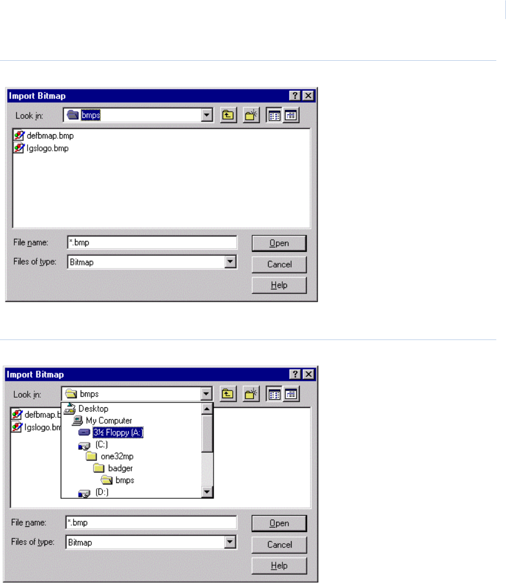
Chapter 10
Badge Design
291
Figure 198.Import Bitmap window
Select the bitmap file to import by clicking on it so that it is highlighted and click Open.
Figure 199.Import Bitmap
Click the down arrow to the right of the Look in field at the top of the window.
From the scroll list select the Floppy A: Drive.
Topa z
User Manual
292
Figure 200.Import Bitmap
Select the bitmap file to import and click Open.
After the window closes the Bitmap appears on the list of Bitmap available from the Draw, Bitmap,
List.
To access the bitmap for installation into the badge template, from the Badger Photo Badge design
window, select the Bitmap command from the Draw menu. Once the location of the bitmap object
has been set up on the badge, a pick list appears with the file name of available bitmaps, including
any you have imported using the steps above. Use the procedure described previously in this section
to install the bitmap into the badge.
Print Selection
The Select Printer drop-down list allows you to select the photo printer being used.
Chapter 10
Badge Design
293
Figure 201.Select Printer
Parameters
The Parameters menu selection pops up the Badger Options window and allows you to set the Strip
Bar Code Checksum, and Add CC/FC.
Figure 202.Badger Options
Strip Bar Code Checksum
This option, when selected, stops the checksum portion of the bar code information from printing on
the badge. The option may be selected by clicking on the box to the left of the option placing a check
mark in the box. To de-select the option, click the box again to remove the check mark from the box.
Topa z
User Manual
294
Add CC/FC
The Add CC/FC option adds the Company Code and Facility Code to the cardholder number on the
badge. Select the option by clicking on the box to the left of the option and the Company code /
Facility Code is printed on the badge along with the cardholder number. See the example below.
Figure 203.Company code and Facility code example
Company Code
& Facility Code
added to Card#

This chapter includes information on how to add drawings, floor plans, and
pictures to the system as maps.
In this chapter:
Overview. . . . . . . . . . . . . . . . . . . . . . . . . . . . . . . . . . . . . . . . . . 296
Color Graphics Maps . . . . . . . . . . . . . . . . . . . . . . . . . . . . . . . . 296
Operating Topaz Color Graphics . . . . . . . . . . . . . . . . . . . . . . . 297
Configuring Color Graphics . . . . . . . . . . . . . . . . . . . . . . . . . . . 313
Chapter 11 Color Graphics Maps
Topa z
User Manual
296
Overview
This feature is currently not being evaluated by UL.
Color Graphics Maps
The Topaz Color Graphics software is an integrated part of all Topaz Software packages. The
software allows you to add drawings, floor plans, and pictures to the system as maps.
A variety of icons that come with the software, or ones you can create, are assigned to the maps and
represent alarm, access, control points, and map links. When the alarm points the icons represent
generate an alarm condition, the icons flash. Acknowledgement of the alarm is required. You can
then use the access and control icons to lock and unlock doors, turn on lights, and control other
functions that the alarm point has been configured for. The map links allow you to jump between
related maps with a mouse click.
All activity you perform with the Topaz Color Graphics software is archived in the Operator History file
and can be recalled.
Note: For best overall image quality and operating efficiency, make sure the most current video drivers for the card being
used are loaded and minimum of 2 Megabytes of video RAM is installed.
Maps used in the software must be Enhanced Metafile (emf) type files. You can convert AutoCAD,
dxf, jpeg, and bitmap files to emf with third party software such as Paint Shop Pro.
The Topaz Color Graphics software is automatically activated when the Topaz software is started and
you click MAP. It shuts down when you log-off or exit Topaz.
You can hide the Map window by clicking the Minimize button in the top right corner of the map
window.
If you don’t see a MAP button, Color Graphics has not been configured for the workstation. To enable
Color Graphics:
1. Select the Hardware button on the left side of the main screen.
2. Select Workstation.
3. Under Workstation, select the name of your workstation. The name should appear in the
Workstation Name field.
4. Select Alarm Graphics by clicking the mouse in the check box placing a check mark in it.
5. Click Save/Add.
6. Click Refresh Alarm Queue to show the MAP button.
CAUTION: While in the configuration mode, which allows you to add and modify maps and icons, the icons on the
maps is not updated until the color graphics system is placed back into online mode.
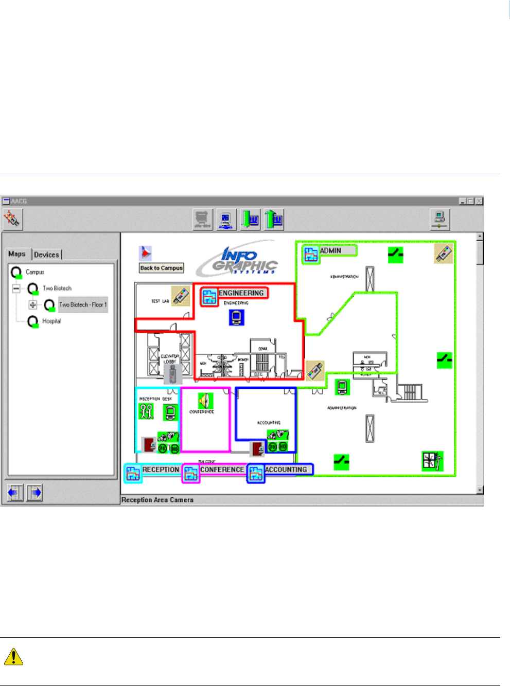
Chapter 11
Color Graphics Maps
297
Operating Topaz Color Graphics
Activating Map Screen
To activate the Topaz Color Graphics Maps, click the Map button in the lower left corner of the screen
or triple-click any alarm in the alarm queue window at the bottom of the screen. A map window like
the following display.
Figure 204.Map window
Map Screen
The Map Screen contains two windows. The window on the left contains the Map and Device Trees.
The Map Tree is a hierarchical view of the maps that have been assigned to the color graphics
system. Click the map name or its icon in the tree to display the map in the map window. The device
tree shows all currently configured device, alarm points, readers, relays, etc. The map window on the
right displays the currently selected map.
CAUTION: Any time a field device is not communicating with the server, all icons associated with the device is
grayed out. When communication is restored, it may take 30 seconds for the map to update and the icons to
reflect the current status.
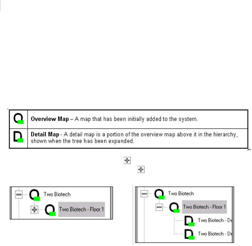
Topa z
User Manual
298
Operating the Map Screen
The map window displays the currently selected map. If there are additional maps assigned to the
color graphics system, they are listed in the map tree in the left window.
To display other maps in the window, select the Maps tab at the top of the Maps / Devices Tree
window. This displays the list of maps that have been added to the color graphics system.
The map tree is a hierarchical list of maps consisting of Overview maps and Detailed maps. Any time
there are maps assigned under an overview, you may need to expand the overview to see the list of
detailed maps under it.
An overview map that is preceded by the sign has additional maps collapsed under it. To see the
list of maps under the overview map, click the in the map tree to expand it, as shown in the
following example.
To view any map in the map window click the map name in the tree.
Map Icons
The icons control different results, depending on the icon type.
The icons on the map represent alarm points, reader doors, relays, security areas, map links, and
cameras. When the mouse pointer is passed over an icon the name of the icon displays in the
bottom left corner of the map window.
Alarm Icons
The interactive map alarm icons change color to show the alarm status in real time.
Green – The alarm is in a normal secure condition and is not masked.
Green Flashing – The alarm has returned to normal condition, but needs to be acknowledged and
cleared.
Red – The alarm has been acknowledged, but has not cleared (reset) yet.
Red Flashing - A new alarm has been activated that needs to be acknowledged and cleared.
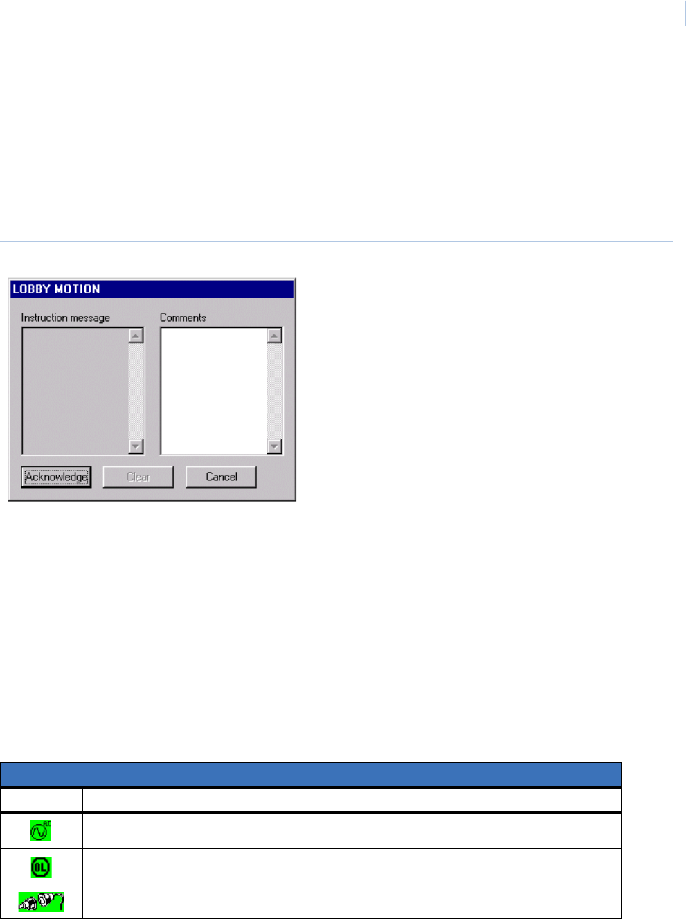
Chapter 11
Color Graphics Maps
299
Blue – The alarm is currently masked and does not generate a new alarm condition, but reports
trouble conditions.
Yellow – A new alarm trouble has been activated that needs to be acknowledged and cleared. The
trouble condition are reported even if the alarm point is masked.
Yellow Flashing – A new alarm trouble has been activated that needs to be acknowledged and
cleared. The trouble condition are reported even if the alarm point is masked.
To acknowledge a flashing alarm point, double-click its icon. The following window displays.
Figure 205.Acknowledge window
The left side of the window may have an instruction message. The right window is for you to type
informational comments about the alarm or actions you take.
Note: DIAMOND II has several common characters which cannot be used. These characters are: Apostrophe ( ‘ ),
Comma ( , ) Greater Than ( < ), Less Than ( > ) and Quote Marks ( “ ).
Click Acknowledge to stop the alarm sound and stop the flashing of the icon. You may then enter
your comments and either click Clear or click Cancel. Cancel closes the window without comments
and allow you to reopen it later to add comments and then click Clear.
There are different types of icons for alarms conditions: door alarm, forced open, and held open.
When you double-click these icons, the Show Details window displays.
Other alarm icons are for general alarms such as intrusion, motion, duress, glass break, high temp,
water leak, etc. There are default icons listed below.
Default Alarm Icons (user assignable/configurable)
Icon Description of Alarm Icon Represents
AC Power Failure - Power to the field panel has failed
Device Offline - Communication to the field device has failed
Door Alarm - Magnetic door contacts on the reader doors.
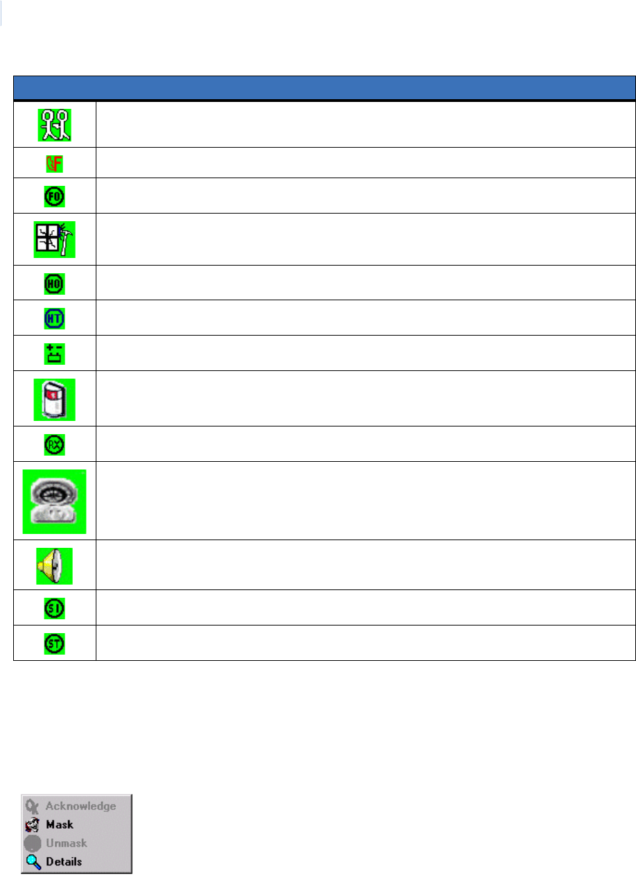
Topa z
User Manual
300
Masking Alarm Points
To Mask or Unmask the alarm point, right-click the icon and a menu displays next to the icon. From
the menu you can select any of the options that are not grayed out. In the following example the only
options are Mask and Details. If the alarm was currently masked or configured as a non-maskable
alarm point, the Mask option would also be grayed out.
Click the option you want to select it.
Duress Alarm - When a duress PIN code has been entered at the keyboard.
Fire Alarm - Auxiliary output from fire panel has activated.
Forced Open - When a reader door is open without authorization.
Glass Break - Alarm glass break detector has been activated while not masked.
Held Open - When a door is not secured within the allowed time set in the reader configuration.
High Temperature - The temperature in the room has risen above the set threshold.
Low Battery - The DC Battery in the field controller has dropped below the required voltage.
Motion Detector - Alarm motion detector has been activated while not masked.
Request to Exit - A request to exit has been received from the reader door.
Smoke Detector - Auxiliary output from fire panel for a smoke detector has been activated.
Standard Alarm - Other types of alarm points not covered by any other default alarm category
System Input - Low Battery or AC Power Failure.
System Tamper - Field controller panel door has been opened.
Default Alarm Icons (user assignable/configurable)
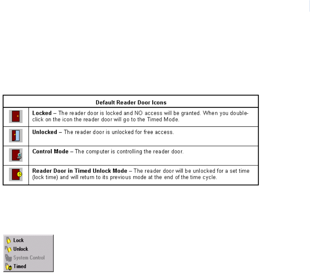
Chapter 11
Color Graphics Maps
301
You can also place the mouse pointer on the icon, highlighting it. This makes the Mask, Unmask, and
Toggle Mask icons appear in the top left portion of the toolbar. While the icon is highlighted, click the
desired button on the toolbar.
Reader/Door Icons
There are four reader door icons, described below.
Note: The door icon on the map is grayed out when the panel is offline (not communicating with the server).
To change the status of the reader door, right-click the reader door icon and a menu displays next to
the icon. From the menu you can select any of the options that are not grayed out. In the following
example the options available are Lock, Unlock, and Timed.
Click the option you want to select it.
You can also double-click the reader door icon to have it open (unlock) the door for the pre-set
unlock time. For example, if you double-click the door icon, it sends an Unlock Timed command to
the door. At the end of the time cycle the reader door returns to its previous mode (System Controlled
or Locked).
Note: The door stays unlocked for its configured lock time, but the icon on the color graphics map only changes to the
timed unlock icon for about 3 seconds.
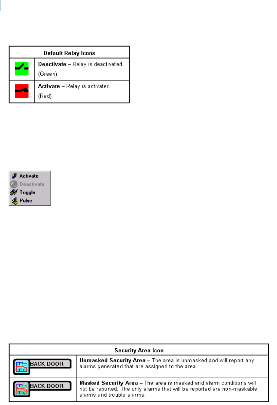
Topa z
User Manual
302
Relay Icons
Note: The relay icon on the map is grayed out when the panel is offline (not communicating with the server).
There are three types of relay actions: activate, deactivate, and pulse. When you double-click the
icon it pulses (activates) the relay for less than one second.
To control a relay, right-click the relay icon to display a menu. From the menu you can select any of
the options that are not grayed out. In the following example the options available are: Activate,
Toggle, and Pulse.
Activate – When clicked, the relay activate and does not change until the deactivate command is
sent by you or the system.
Toggle – When clicked, the relay changes to the opposite of its current state. For example, if the
relay is activated, when the toggle is clicked, the relay deactivates.
Pulse – When clicked, the relay activates for just under one second and then deactivate.
Click the option you want to select it.
You can also double-click the relay icon on the map, which pulse the relay, activating it for just under
one second and then deactivate it.
Note: The relay pulses (about.5 seconds), but the pulse icon shows on the color graphics map for about 3 seconds.
Security Area Icons
There is only one (1) icon for each Security Area. The icon changes to indicate if the area is Masked
or Unmasked.
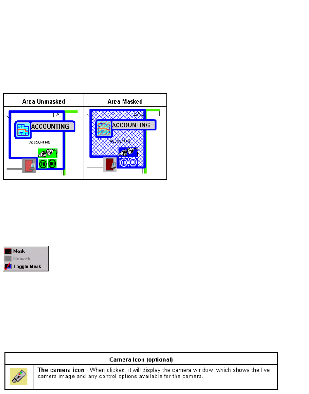
Chapter 11
Color Graphics Maps
303
Color Coded Security Areas
The security area may be color-coded. This changes the black outline of the icon and area name to a
selected color. The area of the map that covers the security area may be outlined as well. The color
of the outline on the map is the same color as the outline of the icon, as in the example below.
Figure 206.Color coded security areas
Notice that the alarm icons change from green to blue when the area is masked.
Masking Security Areas
To Mask or Unmask a security area, right-click the security area icon to display a menu next to the
icon. From the menu you can select any of the options that are not grayed out. In the following
example the only options are Mask and Toggle Mask. Any alarms assigned to the area that are
configured as non-maskable is not masked.
Click the option you want to select it.
You can also place the mouse pointer on the icon, highlighting it. This makes the Mask, Unmask, and
Toggle Mask icons appear in the top left portion of the toolbar. While the security area icon is
highlighted, click the desired button on the toolbar.
Camera Icon
Camera Icon (optional)
The following example shows the camera window with the location of the pan & tilt, zoom, focus, iris,
preset features, and how they operate. Most cameras do not have all of these features. Only the
features that are available and configured for the camera appears in the window.
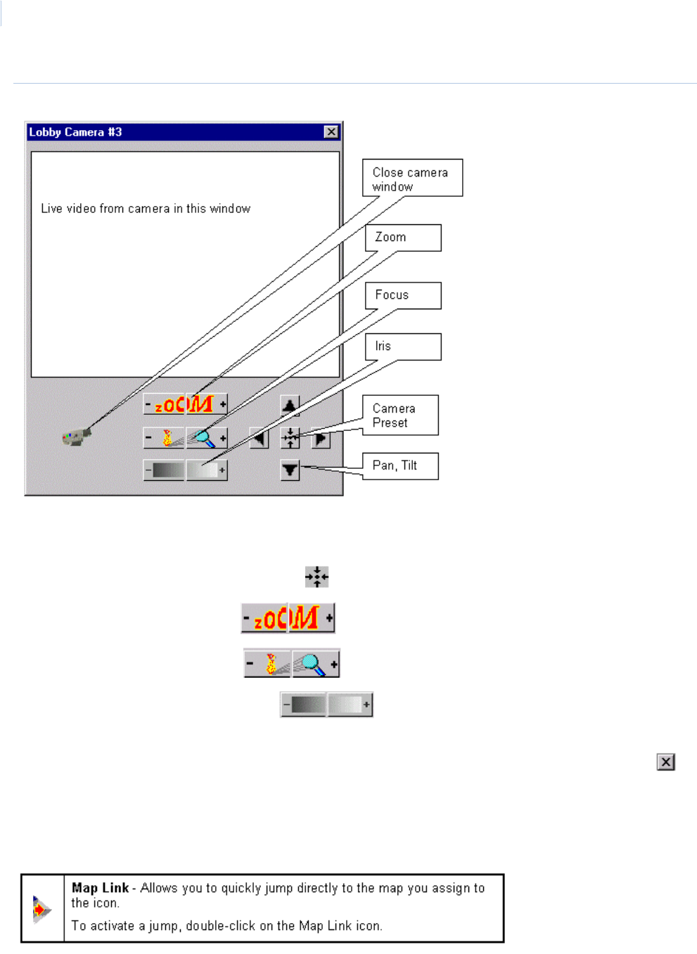
Topa z
User Manual
304
Figure 207.Camera window
Pan the camera by clicking the left and right arrows.
Tilt the camera by clicking the up and down arrows.
Initiate the camera’s preset by clicking the button in the center of the arrows.
Zoom the camera by clicking the – and + buttons.
Focus the camera by clicking the – and + buttons.
Adjust the camera’s iris by clicking the – and + buttons, which lighten and darken the
image.
Close the window by clicking on the Animated Camera button in the bottom left corner or the in
the top right corner of the window.
Map Links
A Map Link allows you to display the maps that have been assigned to the icon.
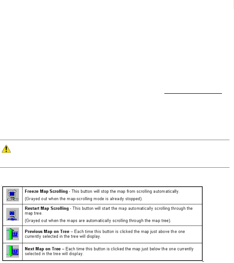
Chapter 11
Color Graphics Maps
305
Toolbar
The toolbar at the top of the map window contains buttons you can click to:
• Manually scroll through the map tree.
• Automatically scroll through the map tree.
• Select configuration mode.
• Issue commands to selected points.
The buttons that appear at the left end of the toolbar changes as the mouse pointer is passed over
different types of icons on the map.
When you want to change the current status of an icon on the map, the quickest and easiest way is
to right-click the icon for the menu, but you may also pass the mouse pointer over the icon. This
highlights the icon, selecting it for action. The icon on the map stays highlighted and selected until
the mouse is passed over another icon, highlighting it for action.
After making sure you have the correct icon highlighted and the name appears in the bottom bar of
the map window, you can then move the mouse to the toolbar and click the button for the action you
want to take.
Map Function Buttons
CAUTION: Make sure you have the correct icon selected before taking any action. Once an icon on the map is
selected and highlighted, you must be careful not to pass the mouse over any other icon while moving the mouse
to the toolbar. As stated above, once the mouse pointer is passed over another icon, that icon is then selected and
highlighted. This could cause you to take action on the wrong icon.
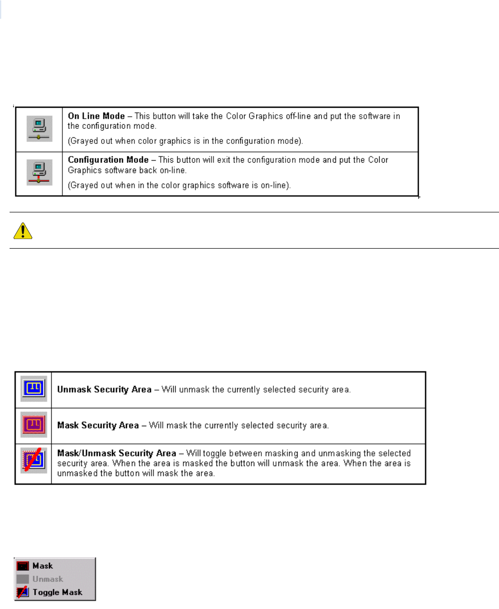
Topa z
User Manual
306
Configuration Button
The Configuration button at the right end of the toolbar allows you to take the Color Graphics
software offline and enter the configuration mode where you can set up maps and icons.
The following buttons only appear in the upper left corner of the toolbar after the mouse has selected
an icon on the map.
Security Area Masking Buttons
When a security area icon is selected on a map by placing the mouse pointer on it, the following
buttons appear in the top left corner of the toolbar. When masking a security area all alarm points
linked to the area are masked unless they are configured as a non-maskable alarm point.
You can also right-click the security area icon to display a menu next to the icon. From the menu you
can select any of the options that are not grayed out. In the following example the only options are
Mask and Toggle Mask. Even if Mask is selected, any alarms assigned to the area that are
configured as non-maskable are not masked.
Click the option you want to select it.
CAUTION: While in the configuration mode, if alarms linked to icons on the maps are activated, the icons are not
updated until the color graphics system is back online.
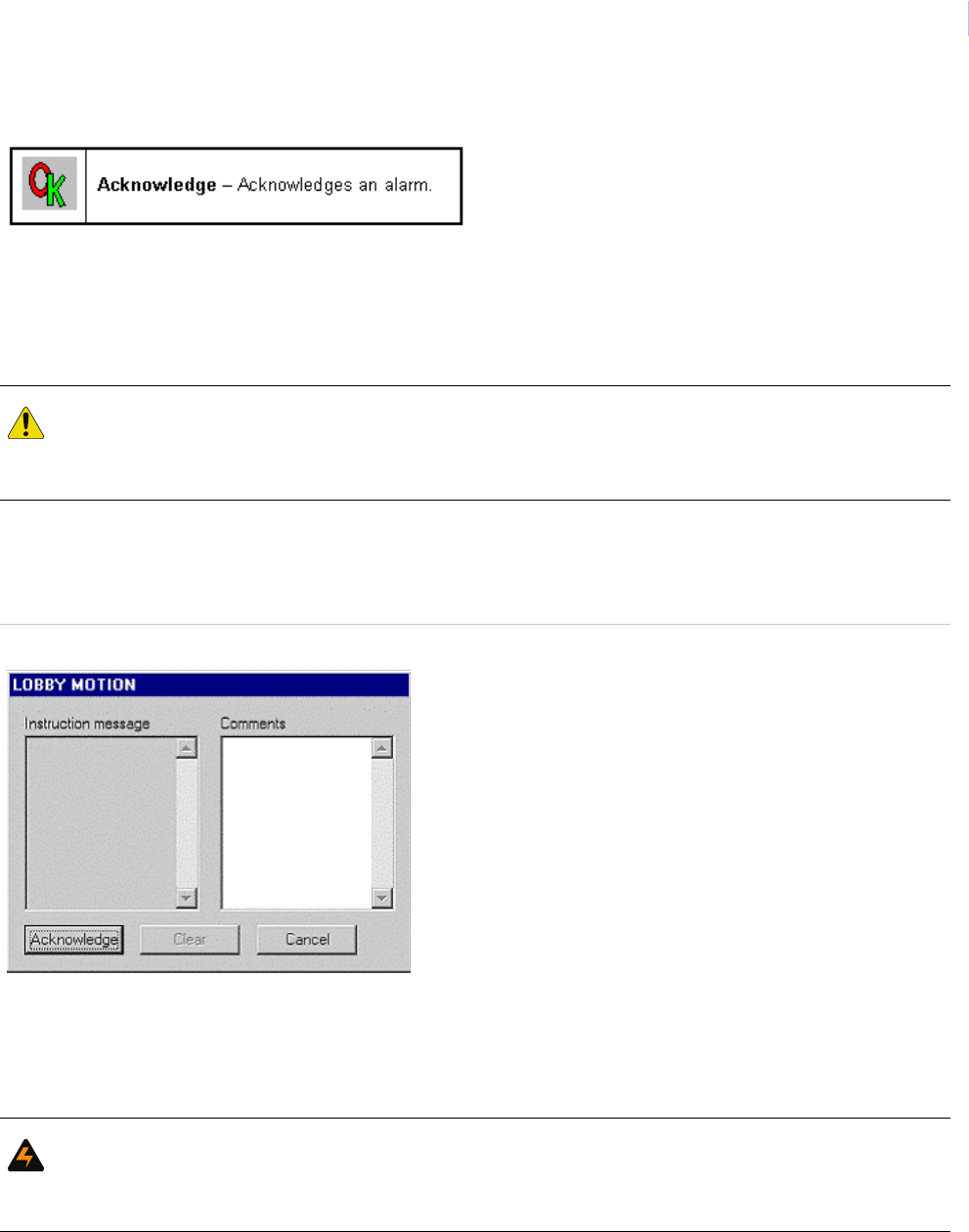
Chapter 11
Color Graphics Maps
307
Acknowledge Alarm
To use this button to acknowledge a new alarm or an alarm that has returned to normal you must first
select the alarm by passing the mouse over the alarm icon requiring acknowledgement. You can
then click OK to acknowledge the alarm.
If you are acknowledging an alarm that has returned to normal, don’t forget to clear it.
The easiest and quickest way to acknowledge and clear the alarm is to double-click the icon to
display the Alarm Detail window or right click the icon to display the menu and click the Details
selection
Figure 208.Acknowledge window
Type any informational comments about the alarm or actions you take and click Clear. If you click
Cancel the window closes without clearing the alarm or saving any comments. You can open the
window at any time to type comments and clear the alarm. Once the alarm is cleared, the window
when displayed is blank once again.
Note: You may only clear an alarm that has returned to normal.
CAUTION: Make sure you have the correct icon selected before taking any action. Once an icon on the map is
selected and highlighted, you must be careful not to pass the mouse over any other icon while moving the mouse
to the toolbar. As stated above, once the mouse pointer is passed over another icon, that icon is then selected and
highlighted. This could cause you to take action on the wrong icon.
WARNING: If you have acknowledged an alarm that has returned to normal and you do not clear it, the icon for that
point will be green and appear to be normal. Until the alarm is cleared, new alarms for that point will only turn the
icon to steady red on the color graphics map. We suggest that once an alarm has returned to normal, you clear it
right away.
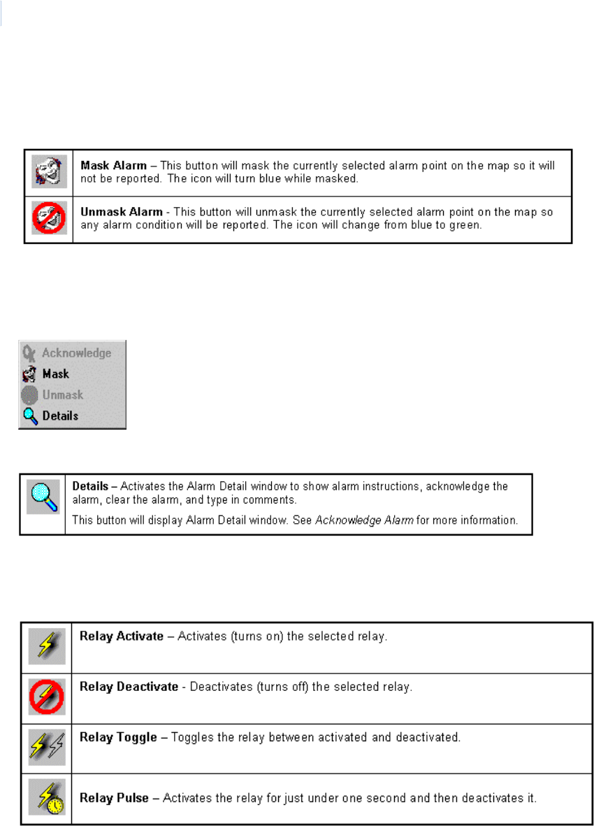
Topa z
User Manual
308
Alarm Point Masking Buttons
When an alarm icon is selected on a map by placing the mouse pointer on it, the following buttons
appear in the top left corner of the toolbar.
To mask or unmask the alarm point, right-click the icon to display a menu next to the icon. From the
menu you can select options that are not grayed out. In the following example the only options
available are Mask and Details. If the alarm were configured as a non-maskable alarm point the
Mask option would also be grayed out.
Click the option you want to select it.
You can also double-click the alarm point icon on the map to display the Alarm Detail window.
Relay Control Buttons
Double-clicking the relay icon on the map also toggles the condition of the selected relay. For
example, if the relay is active, when you double-click the icon, it deactivates the relay and vice versa.
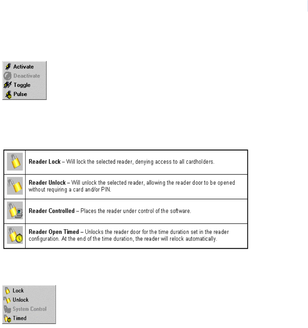
Chapter 11
Color Graphics Maps
309
You can also right-click the relay icon to display a menu next to the icon. From the menu you can
select any of the options that are not grayed out. In the following example the options available are
Activate, Toggle, and Pulse.
Click the option you want to select it.
Reader Control Buttons
These buttons control the selected reader.
To change the status of the reader door, right-click the door icon to display a menu next to the icon.
From the menu you can select any of the options that are not grayed out. In the following example
the options available: are Lock, Unlock, and Timed.
Click the option you want to select it.
You can also double-click the reader door icon to have it open (unlock) timed. For example, if you
double-click the door icon, it sends an Open Timed command to the door. At the end of the time cycle
the reader door returns to it’s previous mode.
The open time is the unlock time in seconds that was selected during the reader’s set up.
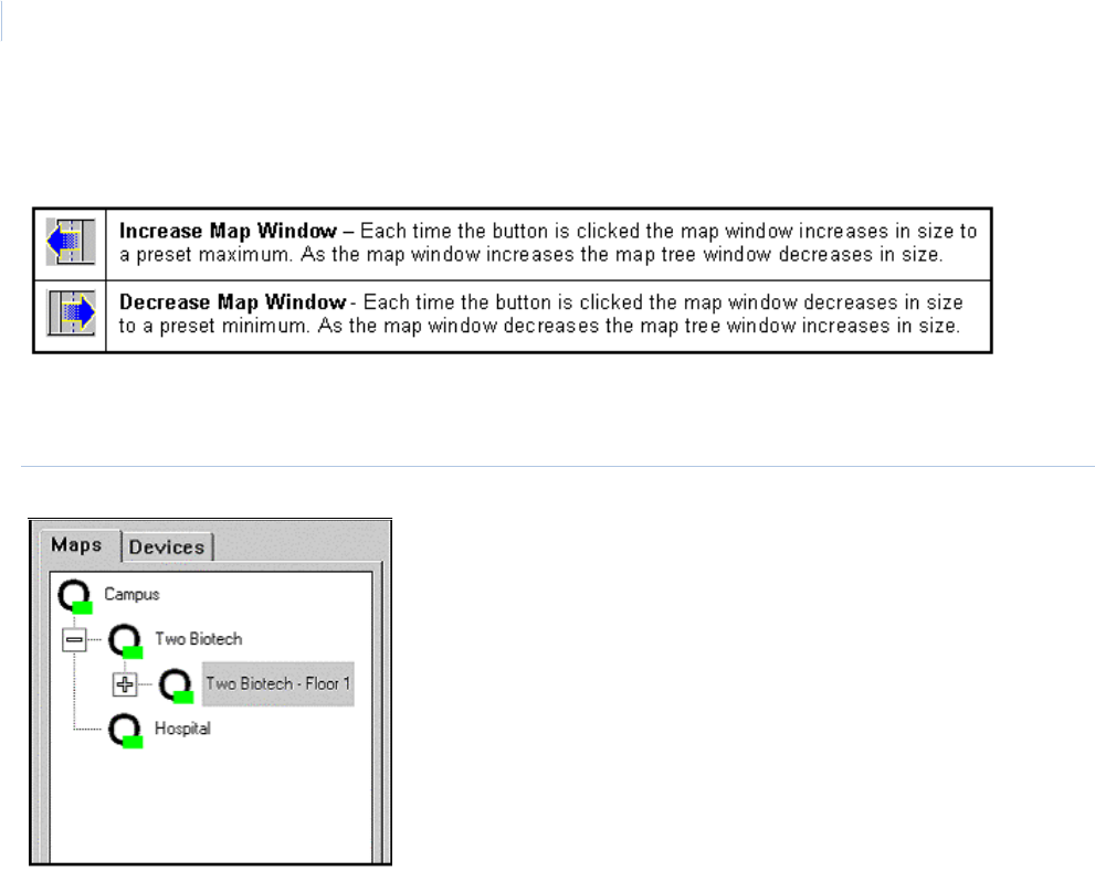
Topa z
User Manual
310
Map Window Sizing Buttons
These buttons control the size of the map and tree windows.
Map Tree and Devices Window
Figure 209.Map Tree and Devices window
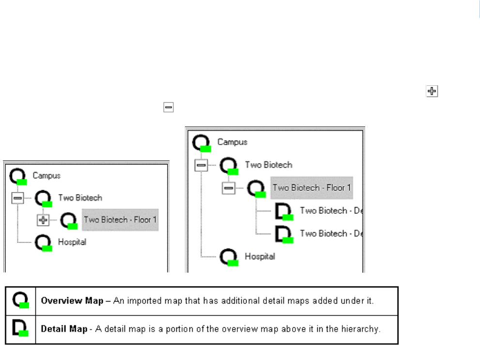
Chapter 11
Color Graphics Maps
311
Maps Tab
The Maps Tab displays a hierarchical view of all maps with their assigned names. Each map’s
placement in the tree is determined by when it was added to the system. You can click the
buttons to expand the tree and the buttons to collapse the tree.
You can select a map from the tree by clicking on the map name, which displays it in the map
window.
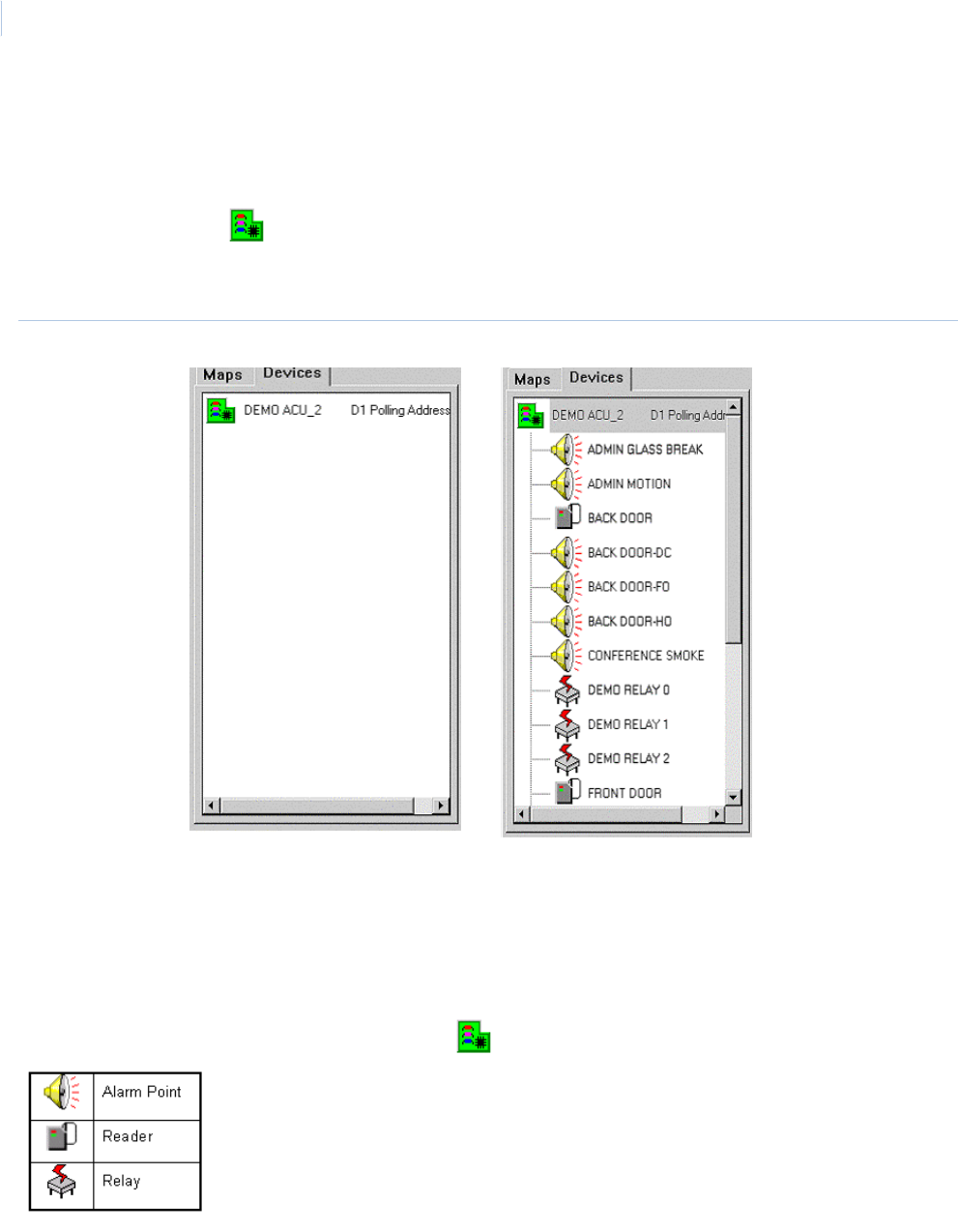
Topa z
User Manual
312
Device Tab
Clicking on the Device tab displays the list of field devices (ACUs, etc.) that are currently configured
in the system, as shown below.
Double-clicking on the device icon or device name expands the device tree as shown below. The
device tree lists all alarm points, readers, and relays that are currently configured in the system for
the device.
Figure 210.Device Tree
The device tree is used to locate the map an icon is currently assigned to, add icons to the maps,
and control the device points. If you click a device name in the tree that is already assigned to a map,
the map it is assigned to displays in the map window and the icon on the map highlights.
Device Point Icons
There are three types of point icons under the device icon in the device tree.
You can control a point listed in the device tree by clicking on it and the corresponding control
buttons display in the toolbar above the tree. You can then click the desired button to control the
selected device point.
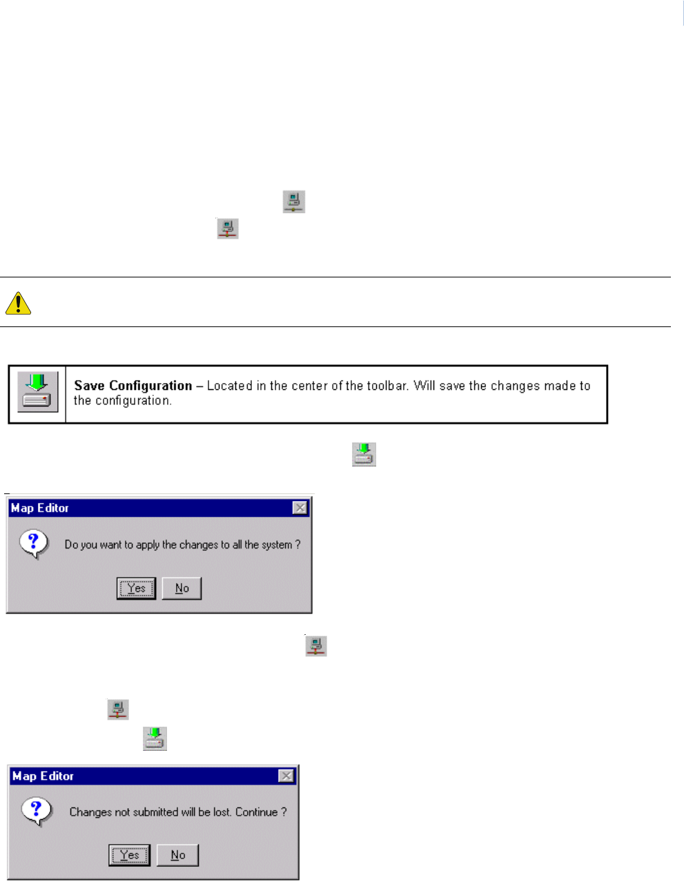
Chapter 11
Color Graphics Maps
313
Configuring Color Graphics
Adding Maps
To add a map to the Map Tree you must place the Topaz Color Graphics system into the
configuration mode. Do this by clicking the Go to Configuration Mode icon in the right end of the
toolbar. The icon changes to the Go to Online Mode icon showing you are in the configuration
mode.
When you have finished with the configuration, click Save Configuration and the following
message displays.
Click Yes to save the changes and then click Go to Online Mode to return to the Online Mode.
Click No to return to the configuration mode without saving any changes.
When you click Go to Online Mode to return to the online mode, if you have made changes,
and have not clicked Save Configuration the following message displays.
Clicking Yes disregards your changes and returns to the online mode.
CAUTION: While in the configuration, alarms linked to icons on the maps are updated until the color graphics
system is placed back online.
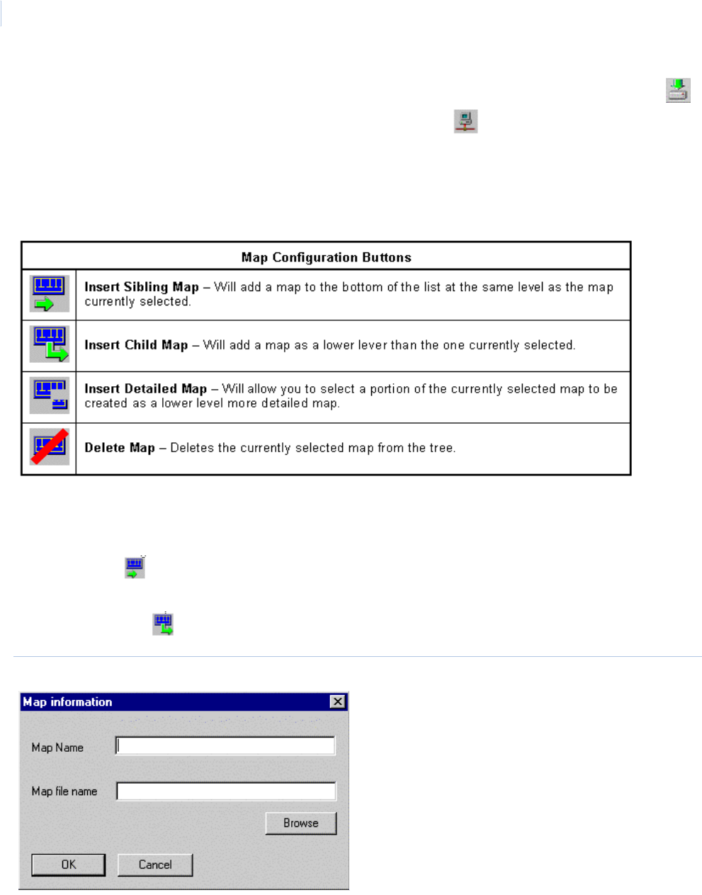
Topa z
User Manual
314
Clicking No closes the message and returns you to the configuration mode. You can then click
Save configuration to save your changes and then click again to return to the online mode.
While in the configuration mode, the buttons on the toolbar do not change, unless you click a device
point in the tree.
Map Configuration Buttons
Add Sibling or Child Map
To add a Sibling map to the tree, select a map in the tree at the level you want the new map to be
placed in. Click Sibling Map and the Map information window below displays.
To add a Child map to the tree, select the map in the tree that you want the new child map to be
placed below. Click Child Map and the Map information window below displays.
Figure 211.Map information
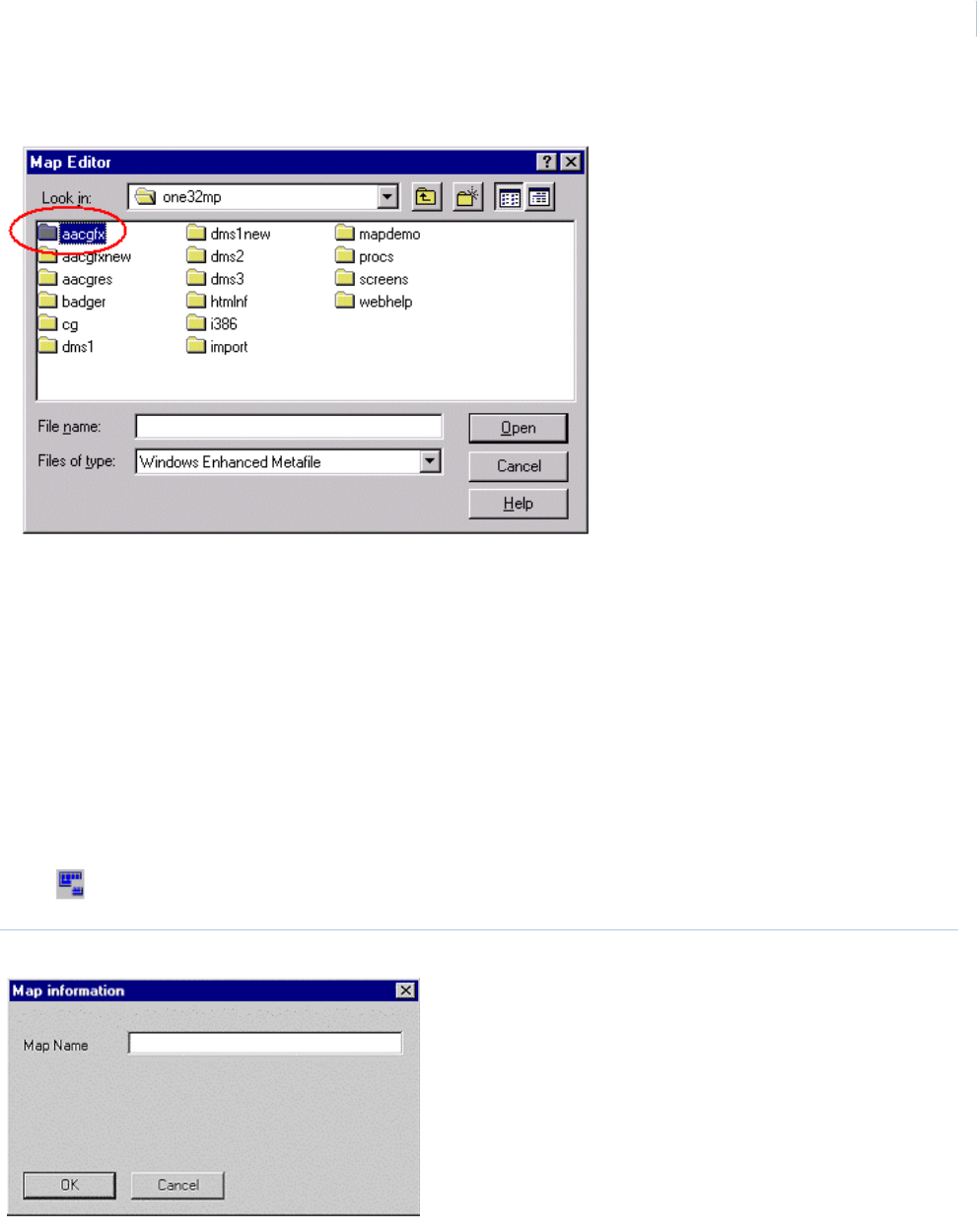
Chapter 11
Color Graphics Maps
315
Click Browse to locate the map file to add and the following window displays.
Using the standard Windows convention, locate the map file you wish to add. Click Open and the
map are copied to the aacgfx directory.
Note: The only map files that can be added to the Color Graphics system must be an Enhanced Metafile format and
have the .emf extension.
Detailed Map
A detailed map is created from a portion of a current map in the tree by drawing a rectangle around
the area you want to become the new detail map. This allows you to have an overview map of a
building and then a more detailed cut away of an area or room from the building overview map.
To add a detailed map to the tree, select the map in the tree you want to make the detail map from.
Click Detailed Map and the Map information window below displays.
Figure 212.Map information window
Enter the Map Name that displays with the icon on the map and click OK.
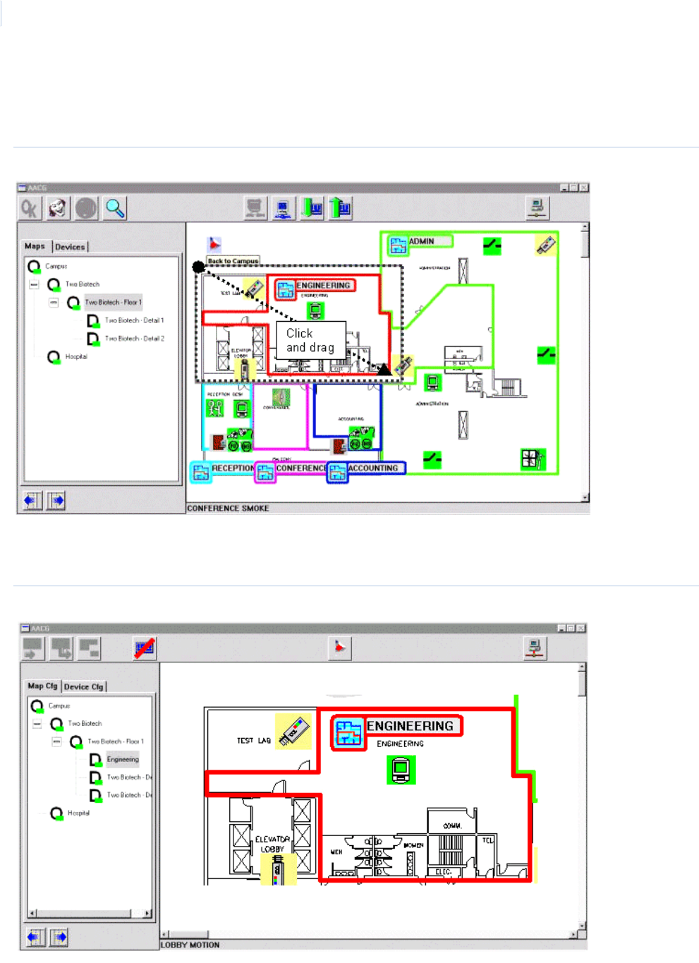
Topa z
User Manual
316
Select the area to be saved as the new detailed map by placing the mouse pointer at the starting
point on the map, then click and hold the left mouse button while dragging a rectangle around the
desired area on the map.
Figure 213.Sample detailed map
When you release the mouse button, the area you selected becomes the new detailed map in the
map tree with the name you entered. All icons in the selected area are also placed in the new map.
Figure 214.Sample detailed map
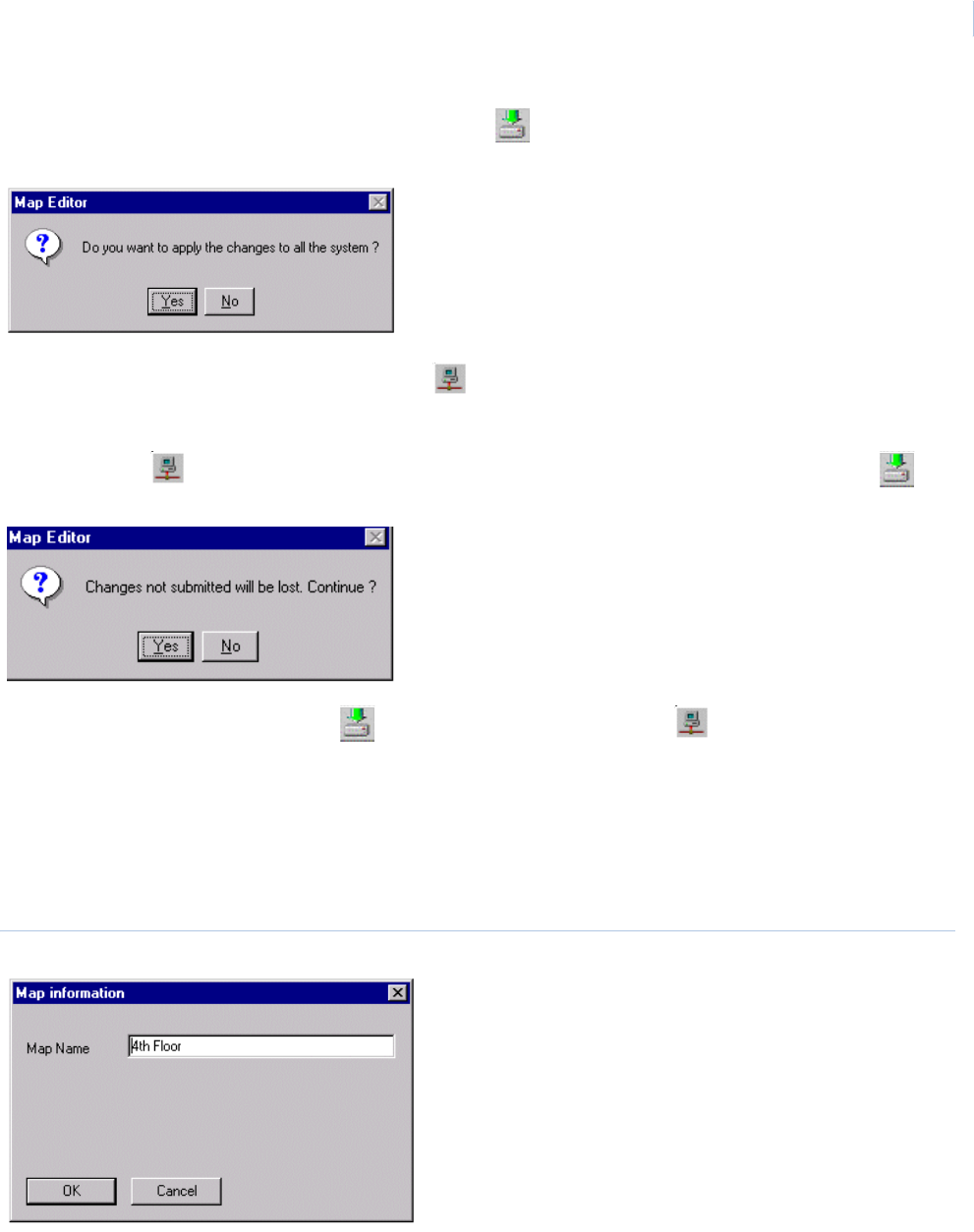
Chapter 11
Color Graphics Maps
317
When you have finished with the configuration click Save Configuration and the following
message displays.
Click Yes to save the changes and then click Go to Online Mode to return to the online mode.
Click No to return to the configuration mode without saving any changes.
When you click Go to Online Mode to return to the online mode, if you have not clicked
Save Configuration the following message displays.
Click No to exit the message. Click Save Configuration and then Go to Online Mode to
return to the online mode.
Click Yes to discard your changes and return to the online mode.
Rename Map
To rename a map in the map tree double-click the map name and the following window is displayed.
Figure 215.Map information
Type the new map name and click OK.
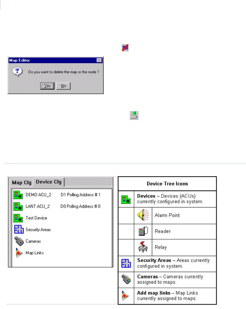
Topa z
User Manual
318
Deleting Map
To delete a map from the tree select the map to be deleted by clicking on the map name in the tree.
When the map displays in the map window, click Delete Map and the following message displays.
Click Yes to delete the map or No if you do not.
When you have finished with the configuration click Save Configuration to save your changes.
Adding Points to Map
To add a point to a map, select the map to add points to from the tree, then select the Device tab.
Double-click any type icon to expand the list of configured device points.
Figure 216.Expanded list of configured device points
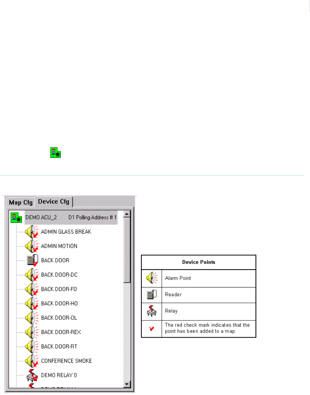
Chapter 11
Color Graphics Maps
319
There are six types of icons in the tree that you can add to a map. Three (3) are device points.
• Device Points
•Alarms
• Readers
• Relays
• Security Areas
• Cameras (Optional)
• Map Links
These icons are described in detail in the following sections.
Adding Device Points to Map
Double-click the Device icon to expand the Device Tree for a list of currently configured points
that can be added to the map.
Figure 217.Expanded Device Tree
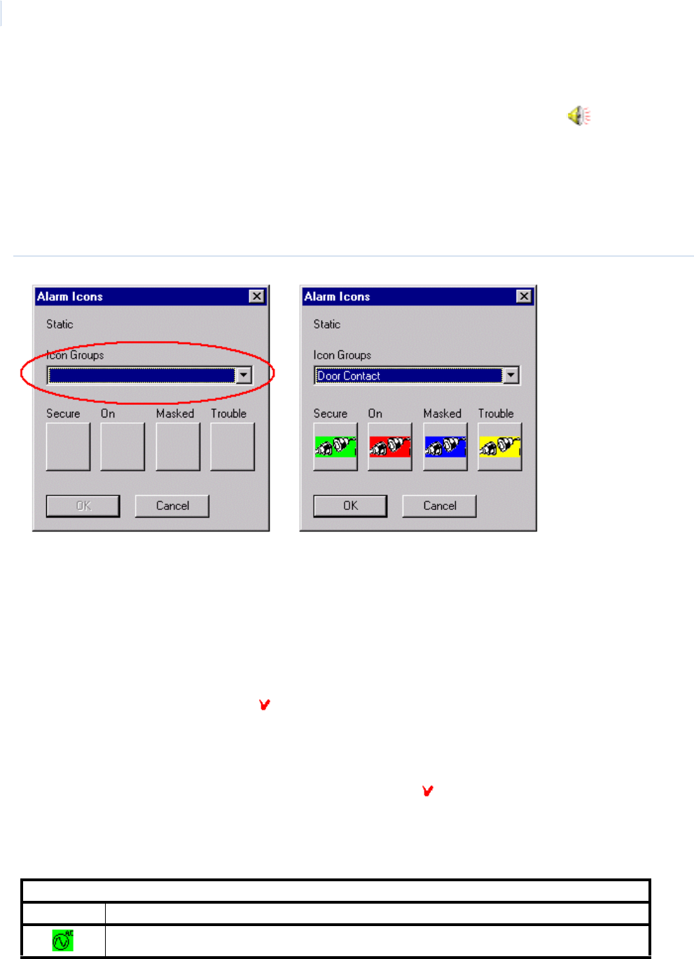
Topa z
User Manual
320
Adding Alarm Points to Map
In the Device Tree, locate the alarm point to add. Place the mouse pointer on the alarm icon,
click, and hold down the left mouse button. Drag the icon on the map, and release the mouse button.
When you release the mouse button after dragging the alarm icon onto the map, it opens the Icon
Group window. Then you can assign the icon group that is used for the point you placed on the map.
From the Icon Group drop-down list select the Icon Group you want for the point by scrolling through
the list and clicking on the name on the group.
Figure 218.Icon groups
After you click the name of a icon group, the four icons configured for the group appears in the blocks
below each of the point designations.
To move the icon to a different location on the map, click and hold the left mouse button on the icon
and drag the icon to a new location on the map.
Note: When placing a new point on the map, the icon defaults to a green secure icon even if the point is an active alarm.
When the color graphics is back to online, it checks for the current status of the point and changes the icon
accordingly.
The alarm icons in the tree with the red check mark have already been added to a map and
cannot be added again. If you want to add the icon to a different map you must first delete it from the
current map.
To delete or remove an icon from the map, click and drag the icon back to the tree window and
release the mouse button. The icon disappears and the red check mark on the icon in the tree is
removed.
All the default icons that come already configured on the system are listed below. Additional icon
groups may be added, Check with the system administrator.
Default Alarm Icons (user assignable/configurable)
Icon Description of Alarm Icon Represents
AC Power Failure - Power to the field panel has failed
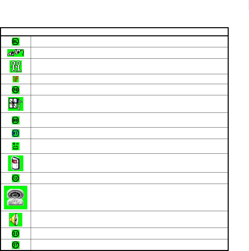
Chapter 11
Color Graphics Maps
321
Note: Default icons shown in the table above represent the alarm condition as secure mode. The icons also have three
others colors that are described below.
The interactive map alarm icons change color to show current status.
Green – In normal secure condition and not masked.
Green Flashing – Returned to normal condition, but needs to be acknowledged and cleared.
Red – Alarm has been acknowledged, but has not cleared (reset) yet.
Red Flashing - A new alarm has been activated that needs to be acknowledged and cleared.
Blue – Alarm is currently masked and does not generate a new alarm condition, but does report
trouble conditions.
Device Offline - Communication to the field device has failed
Door Alarm - Magnetic door contacts on the reader doors.
Duress Alarm - When a duress PIN code has been entered at the keyboard.
Fire Alarm - Auxiliary output from fire panel has activated.
Forced Open - When a reader door is open without authorization.
Glass Break - Alarm glass break detector has been activated while not masked.
Held Open - When a door is not secured within the allowed time set in the reader
configuration.
High Temperature - The temperature in the room has risen above the set threshold.
Low Battery - The DC Battery in the field controller has dropped below the required
voltage.
Motion Detector - Alarm motion detector has been activated while not masked.
Request to Exit - A request to exit has been received from the reader door.
Smoke Detector - Auxiliary output from fire panel for a smoke detector has been
activated.
Standard Alarm - Other types of alarm points not covered by any other default alarm
category
System Input - Low Battery or AC Power Failure.
System Tamper - Field controller panel door has been opened.
Default Alarm Icons (user assignable/configurable)
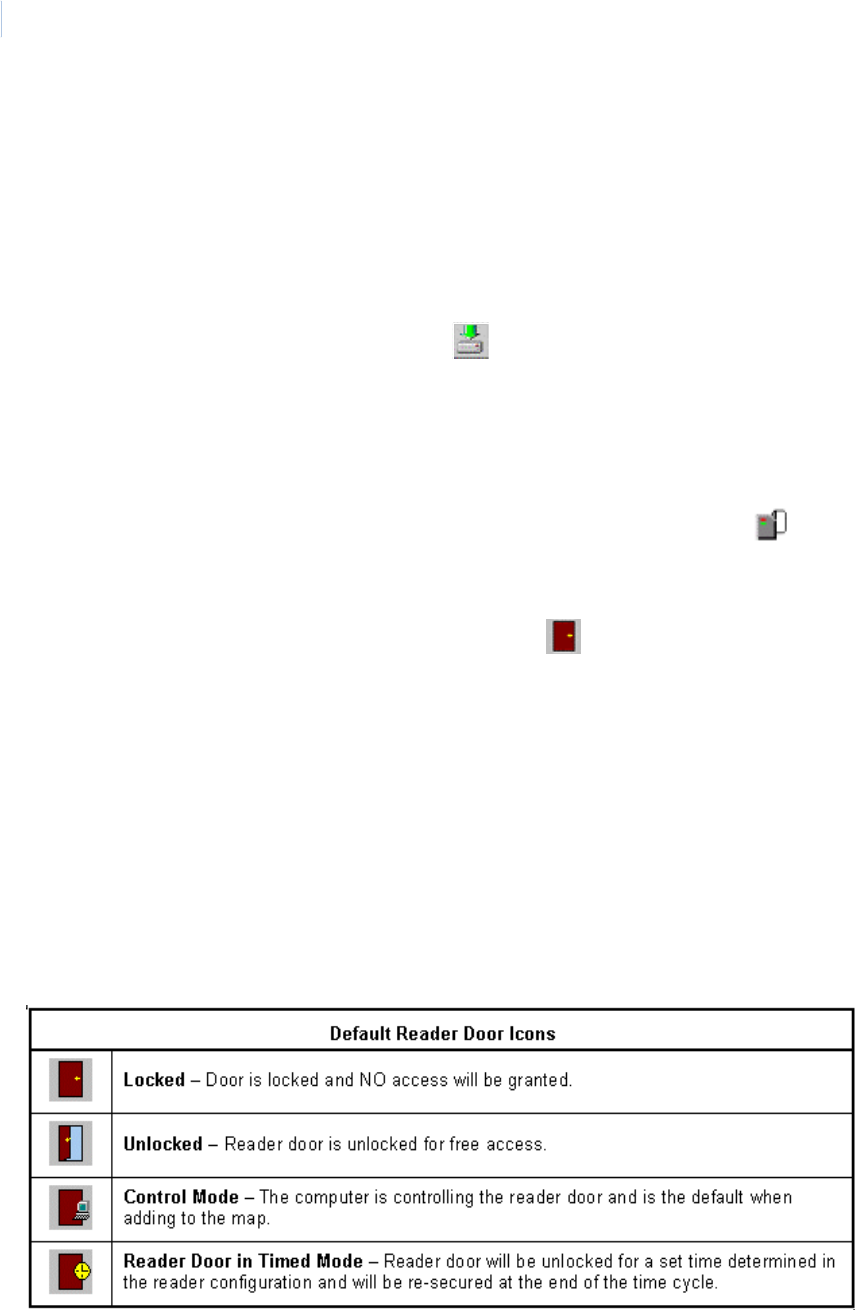
Topa z
User Manual
322
Yellow – A new alarm trouble has been activated that needs to be acknowledged and cleared. The
trouble condition is reported even if the point is masked.
Yellow Flashing – A new alarm trouble has been activated that needs to be acknowledged and
cleared. The trouble condition is reported even if the point is masked.
Note: Because of the versatility of the software, which allows you to configure your own icon, it is possible that the colors
explained above are not the actual colors used. Ask the system administrator if your system has custom
configured icons and confirm your systems icon colors represent the different alarm conditions.
Save your configuration changes by clicking Save Configuration in the center of the toolbar at
the top of your screen.
Note: If you do not save your changes to the configuration, when you exit the program all changes are lost.
Adding Readers to Map
In the Device Tree locate the reader to add. Place the mouse pointer on the Reader icon, click
and hold down the left mouse button while dragging the icon onto the map, and release the mouse
button.
When you release the mouse button it changes to the Reader Locked icon.
If additional custom icon groups have been created for doors (after dragging the reader icon on to
the map and releasing the mouse button), the Icon Groups window is displayed.
Select the icon group you want to use for the reader icon you placed on the map by clicking on the
icon group name.
After you have clicked on the name of a icon group, the four icons configured for the group appears
in the blocks below each of the point designations.
To move the icon to a different location on the map, click and hold the left mouse button on the icon
and drag the icon to a new location on the map.
Note: When placing a new reader point on the map, the icon defaults to a Control Mode type even if the point is in lock
or unlocked mode. When the color graphics is back online, it checks for the current status of the reader door and
change the icon accordingly.
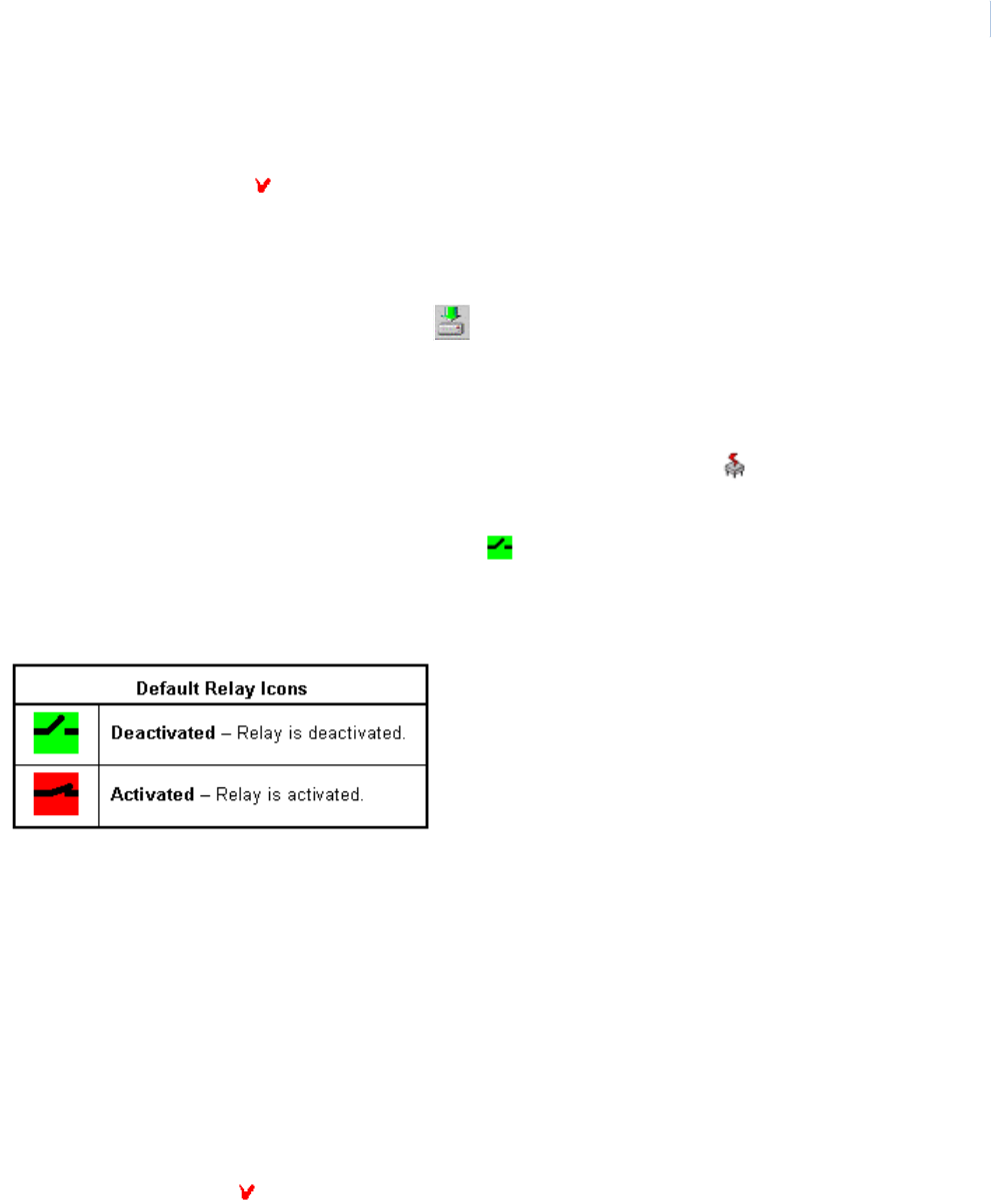
Chapter 11
Color Graphics Maps
323
Note: The door icon on the map is grayed out when the panel is offline (not communicating with the server). When
communication is restored it takes 30 seconds for the icons to reflect the current status.
The reader icons with the red check mark on their icon have already been added to the map.
To delete or remove an icon from the map, click and drag the icon back to the tree window and
release the mouse button. The icon disappears and the red check mark on the icon in the tree is
removed.
Save your configuration changes by clicking Save Configuration in the center of the toolbar at
the top of your screen.
Adding Relays to Map
In the Device Tree locate the relay to add. Place the mouse pointer on the relay icon, click and
hold the left mouse button. Drag the icon onto the map and release the mouse button.
When you release the mouse button it defaults to a deactivated relay icon.
Note: When placing a new relay point on the map the icon defaults to a deactivated relay mode type even if the point is
activated. When the color graphics is back online, it checks for the current status of the relay point and change the
icon accordingly.
If additional custom icons groups have been created for doors (after dragging the relay icon on to the
map and releasing the mouse button), the Icon Groups window is displayed.
Select the icon group you want to use for the relay icon you placed on the map by clicking on the icon
group name.
After you have clicked on the name of a icon group, the two icons configured for the group appears in
the blocks below each of the point designations.
To move the icon to a different location on the map click and hold the left mouse button on the icon
and drag the icon to a new location on the map.
Note: The relay icon on the map is grayed out when the panel is offline (not communicating with the server). When
communication is restored it takes 30 seconds for the icons to reflect the current status.
The relay icons with the red check mark on their icon have already been added to a map.
To delete or remove an icon from the map, click and drag the icon back to the tree window and
release the mouse button. The icon disappears and the red check mark on the icon in the tree is
removed.
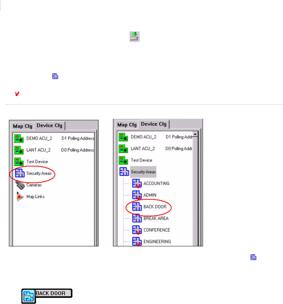
Topa z
User Manual
324
Save your configuration changes by clicking Save Configuration in the center of the toolbar at
the top of your screen.
Adding Security Areas to Map
Double-click the Security Areas icon to expand the Security Areas tree for the list of currently
configured security areas that can be added and cannot be added again. The Security Areas with
the check mark on their icon have already been added to a map.
Figure 219.Security Areas tree
In the Security Area tree locate the security area to add. Place the mouse pointer on the Security
Area icon, click and hold the left mouse button. Drag the icon onto the map, and release the mouse
button.
When you release the mouse button, after dragging the security area icon onto the map, it changes
to an Unmasked Security Area icon with the area name in a thick black outline.
To relocate the icon click and hold the left mouse button to drag the icon to a new location on the
map.
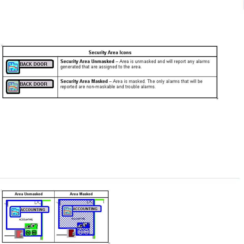
Chapter 11
Color Graphics Maps
325
Note: When placing a new security area on the map the icon defaults to unmasked area icon even if the area is masked.
When the color graphics is back online, it checks for the current status of the area and change the icon
accordingly.
To delete or remove an icon from the map, click and drag the icon back to the tree window and
release the mouse button. The icon disappears and the red check mark on the icon in the tree is
removed.
Save your configuration changes by clicking the icon in the center of the toolbar the top of your
screen.
Color Coding Security Areas
The security area can be color coded and an outline of the area can be drawn in the same color.
When the area is masked, the outline of the area is filled with an overlay of mesh the same color as
set for the security area, as shown below.
Figure 220.Color coded security areas
To color code and outline the security area you must be in the configuration mode. After placing the
security area on the map double-click the security area icon you want to color code and the following
configuration window displays.
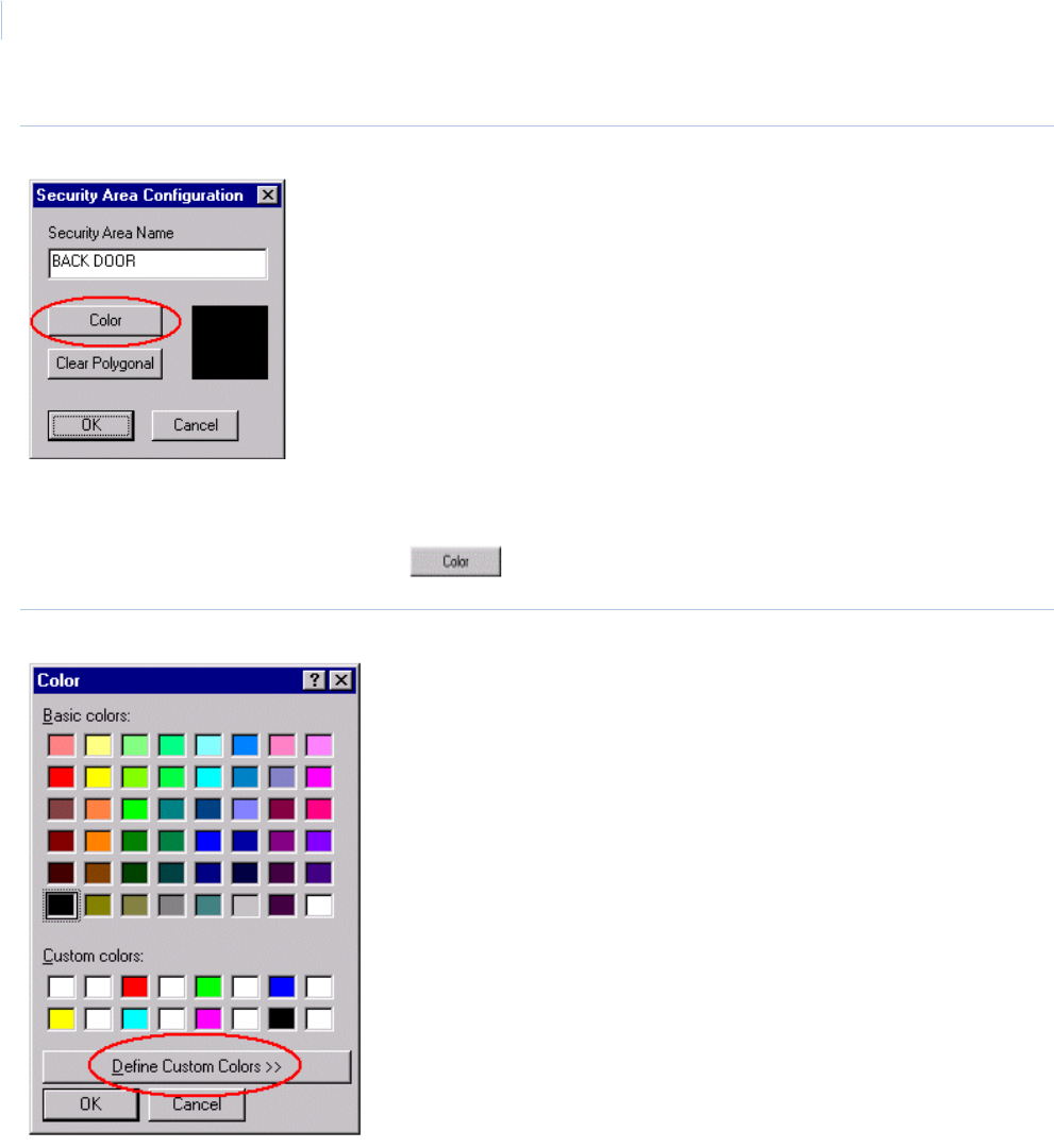
Topa z
User Manual
326
Figure 221.Security Area Configuration
Note: You cannot change the name of the security area in this window. You must go to Security Area page under the
Setup button.
To change the color of the area, click Color and the color window displays.
Figure 222.Color palette
Select the color from the Basic or Custom colors by clicking on the color block. The default black
outline for the area icon changes to the color selected.
You can create your own color by clicking Define Custom Colors.
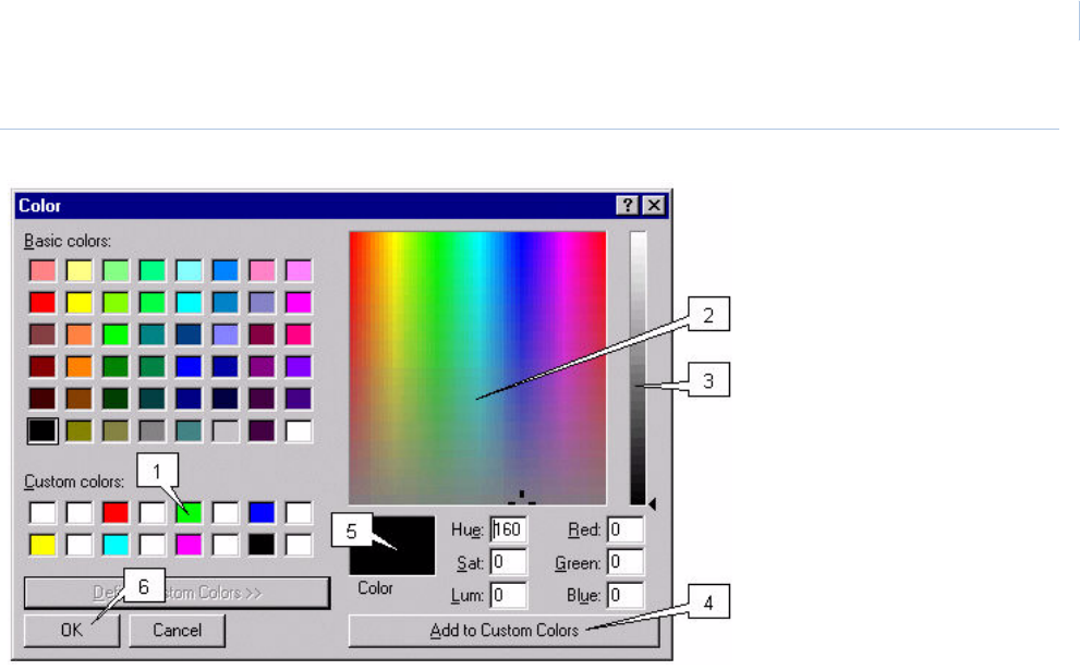
Chapter 11
Color Graphics Maps
327
Figure 223.Define Custom Colors
To create a custom color, follow the steps below (each number in the list corresponds to a number in
the image above).
1. Click the Custom color block to select where the new color will be placed. You can replace an
existing color by clicking that color block.
2. Click the mouse pointer inside the rainbow window to select the general color you want.
3. Click in the slide bar and select the shade of the color. Continue changing the color areas in
step 2 and 3 until the color you want appears in the currently selected color window.
4. Click Add to Custom Colors and the color now appears in the Custom Colors block you
selected earlier.
5. Click the color block to select a color for the security area.
6. Click OK and to return to the Security Area Configuration window.
The Color you selected appears in the color block in the Security Area Configuration window and the
security area icon on the map is outlined with the new color, as shown below.
Topa z
User Manual
328
Figure 224.Security Area Configuration
Click OK to exit the Security Area Configuration window.
Save your configuration changes by clicking Save Configuration in the center of the toolbar at
the top of your screen.
Note: If you do not save your changes, when you exit the program all changes are lost.
Outline Security Area
The security area on the map can be outlined with the same color as the icon’s outline. When the
area is masked the outline of the area is filled in with an overlay of mesh the same color as set for the
security area, as shown below.
Figure 225.Outline Security Areas
Note: The security area does not require an outline. If you do not want the mesh to appear when the area is masked,
then you should not outline it.
To outline the security area you must be in the configuration mode. After placing the security area on
the map, double-click the security area icon to outline. The Security Area configuration window
displays.
If the security area color has not been selected click Color and the color window displays.
Select the color from the Basic or Custom colors for area by clicking on the color block.
Note: Only one color can be selected for both the security area and the icon outlines.
Chapter 11
Color Graphics Maps
329
The Color you selected appears in the color block in the Security Area Configuration window, as
shown below.
Figure 226.Security Area Configuration
Start drawing the outline of the area by placing the mouse pointer at the starting point on the map.
Click the left mouse button once to set the starting point. Move the mouse pointer to the next location
and click the left button once again. Repeat this until the entire area is outlined and you have clicked
the mouse button back on the starting point.
After clicking back on the starting point, each point you clicked has a small square block called a
reshaping handle. These reshaping handles allow you to reshape the outline.
To reshape the outline of the area, place the mouse pointer on top of a reshaping handle, click and
hold the left mouse button as you drag the lines to the desired reshape. The two lines that are joined
at the point move together as you drag the handle.
You can delete the outline and redraw by clicking Clear Polygonal.
When you have completed changes to the Security Area Configuration window, click OK.
Save your configuration changes by clicking Save Configuration in the center of the toolbar at
the top of your screen.
Topa z
User Manual
330
Adding Camera to Map
In the Device tree locate the camera icon. Place the mouse pointer on the Camera icon, click and
hold down the left mouse button. Drag the icon on the map and release the mouse button.
When you release the mouse button (after dragging the camera icon onto the map), the Camera
Configuration window displays as shown below
Figure 227.Camera Configuration.
Clicking Cancel closes the Camera Configuration window and remove the camera icon from the
map.
Enter the Camera Name of up to 35 alphanumeric characters. The camera name field may only
display a portion of the 35 characters, but the title bar on the camera window (shown below) when
called up displays the full name.
Select the number for the camera that corresponds to its number as configured in the video switcher.
Select the Camera Orientation, which is the direction the camera icon should point in the map by
clicking the up and down arrows to rotate the camera 45 degrees each time.
Chapter 11
Color Graphics Maps
331
Select the Camera Features that the camera is set up for. The camera and video switcher’s
capability determine these features. The features that are available are:
•Pan
•Tilt
• Zoom
• Focus
•Iris
• Preset position
If all features were selected, the camera window would display like the example below.
Figure 228.Sample Camera window
When you have completed configuration of the camera, click OK.
To relocate the icon, click and hold the left mouse button and drag the icon to a new location on the
map.
To delete or remove a camera icon from the map, click and drag the icon back to the tree window.
The icon disappears from the map and the red check mark on the icon in the tree is removed.
Save your configuration changes by clicking Save Configuration in the center of the toolbar at
the top of your screen.
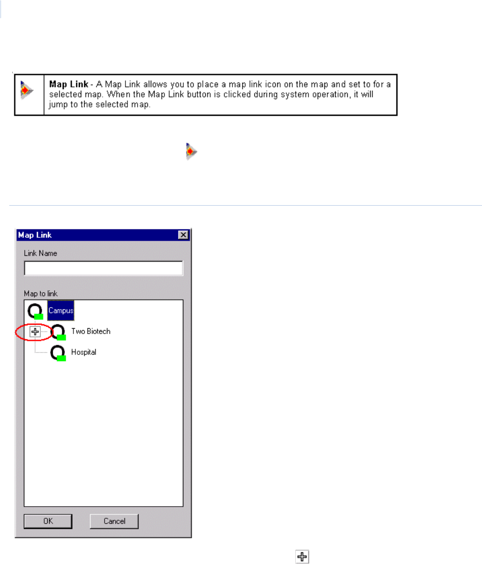
Topa z
User Manual
332
Add Map Links
To add a map link, locate the Map Link icon in the Device tree (it is located in the first level of the
tree). Place the mouse pointer on the Map Link icon, click and hold down the left mouse button.
Drag the icon on the map and release the mouse button.
When you release the mouse button the Map Link window displays.
Figure 229.Map Link window
Highlight the map that you want the link to jump to. Click the in the map tree to expand it if
needed to locate the desired map.
In the Link Name field enter the name for the link.
When you have completed configuration of the map link, click OK.
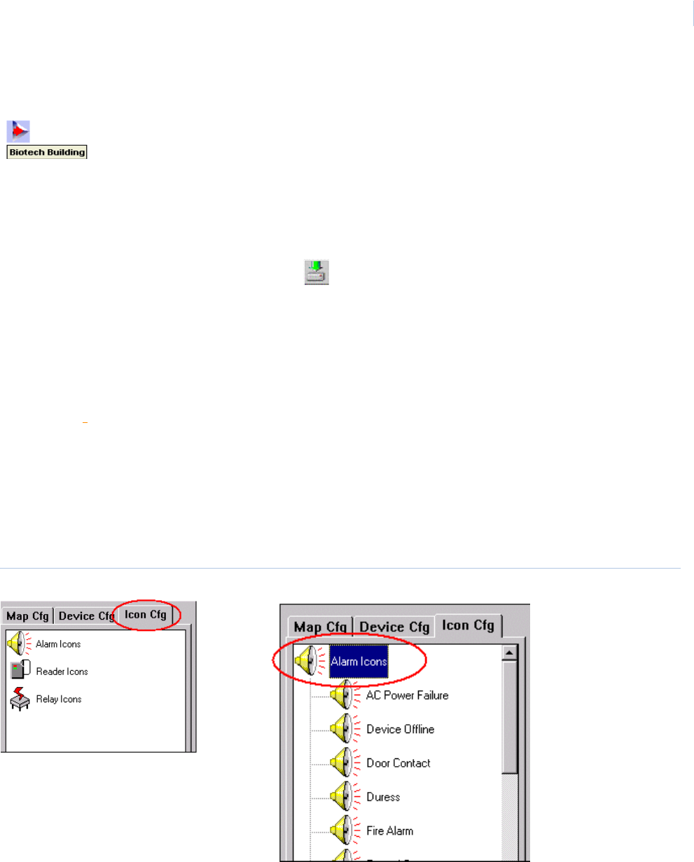
Chapter 11
Color Graphics Maps
333
The Map Link icon on the map changes to a Map Link icon with the link name next to the icon, as in
the following example.
To relocate the icon, click and hold the left mouse button to drag the icon to a new map location.
To delete or remove a map link icon, click and drag the icon back to the tree window and release the
mouse button. The icon disappears from the map and the red check mark on the icon in the tree is
removed.
Save your configuration changes by clicking Save Configuration in the center of the toolbar at
the top of your screen.
Custom ICON Groups
You may create and assign your own group of icons to any alarm, reader, or relay.
Icons must be modified and configured using a bitmap program such as Paint. All Icons should be
saved in the Topaz\aacgfx color graphics directory on your hard drive. The standard size of icon is
approximately 35 x 35 pixels, but can be any size; however, the larger the icon, the more area of the
map it covers.
Note: You should be familiar with configuring the Color Graphics system before creating and assigning custom icons.
You must be in the configuration mode before you begin. Once in the configuration mode, the Icon
Cfg tab displays in the tree window as shown below. Only the Alarm, Reader, and Relay icons show
and are the only icons you can customize.
Figure 230.Icon Configuration
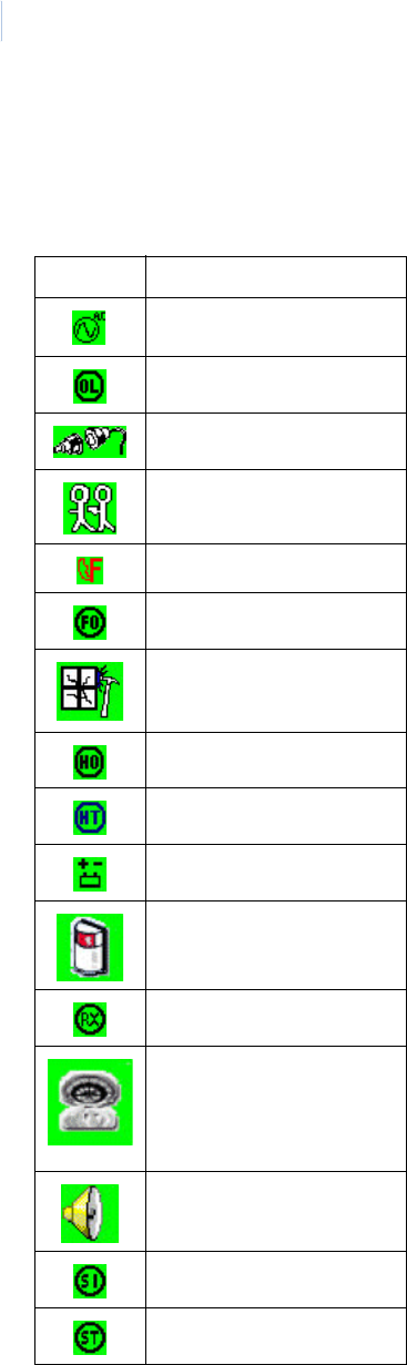
Topa z
User Manual
334
Modify Alarm Icon Group Category
Clicking on the Alarm Icons icon opens the tree and expands the list of icon group alarm categories.
The list of default alarm categories is list below and a portion of the tree shown to the right.
To assign a different icon to a category click the icon group for the category you want to change. The
Icon Group window drops down as shown below. For example, if you click the Door Contact
category, alarm Icons for the Door Contact category display.
Icon Category Description
AC Power Failure
Device Offline
Door Alarm
Duress Alarm
Fire Alarm
Forced Open
Glass Break
Held Open
High Temperature
Low Battery
Motion Detector
Request to Exit
Smoke Detector
Standard Alarm
System Input
System Tamper
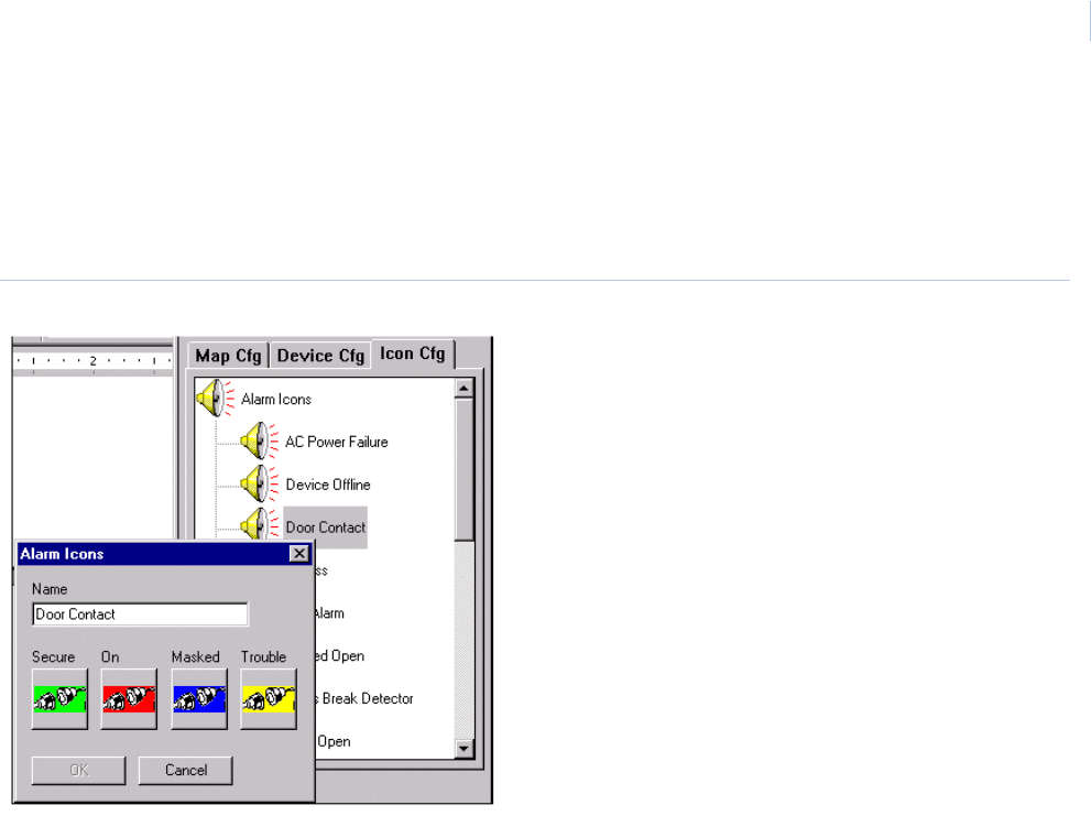
Chapter 11
Color Graphics Maps
335
There are four icons currently assigned to each alarm category: Secure, On, Masked, and Trouble.
Notice the colors match the colors talked about earlier in this document, such as, if the alarm is on
(active) it is flashing red. If you change the icon to an icon with some other color then when the alarm
is on (active) it flashes the new color. This can cause confusion for the operators. It is suggested that
when you modify or create new icons that you keep the colors in mind.
Figure 231.Modify Alarm Icon Group
You must change the icon assigned to each designation (secure, on, masked, trouble) one at a time
by clinking on the icon under the designation name you want to change.
Note: When you are creating a new icon group for a category you should keep each of the four icons the same and only
change the color except for special applications.
For example, to change the Masked icon, click the icon and a disk directory browser window opens.
Locate the icon file you want to assign as the Masked icon as shown on the next page.
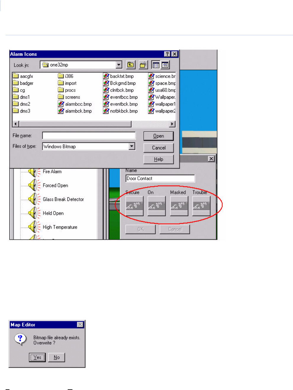
Topa z
User Manual
336
Figure 232.Masked icon
Notice that after you clicked on the icon and the browser window opened, all four icons on the Icon
Group window are now grayed out. If you forget which icon you selected, close the browser window
and reselect the icon again. If you selected the wrong icon file, you can click the icon again to select
another icon file.
Locate the icon file and double-click the file name to have it assigned. The browser window closes
and the new icon is shown in the Icon Group window as the new icon assigned to Masked.
If you select an icon that is already assigned to another icon group, the message Bitmap file
already exist. Overwrite?
You can continue to use the icon in your new category as well as the existing icon group by clicking
Yes. Other wise click No and the icon is not added to the new icon group. You can then select a
different bitmap.
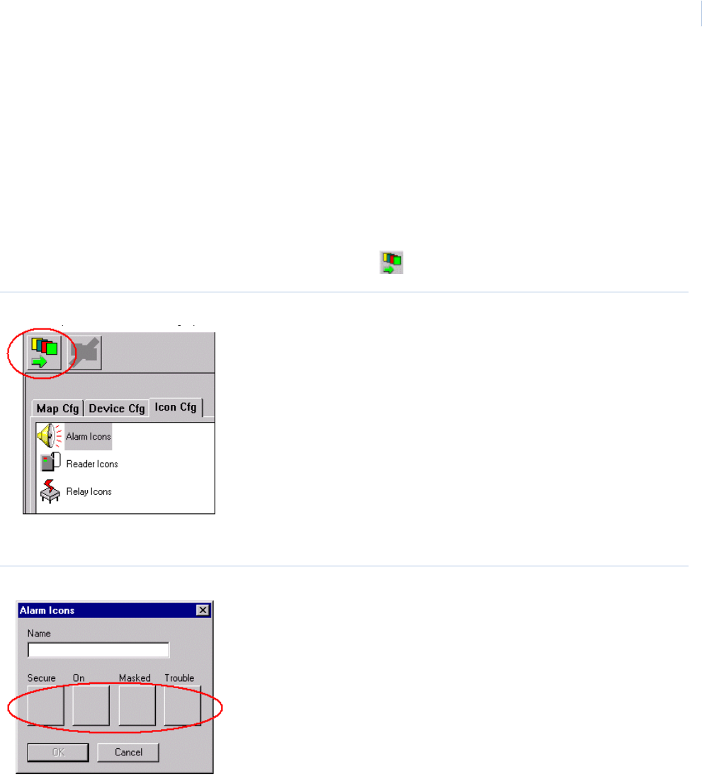
Chapter 11
Color Graphics Maps
337
After selecting all four icons, click OK to save your changes.
If you click Cancel on the Icon Group window, the icons revert back to the icons assigned to the icon
group category when you first opened the Icon assignment window.
The icon group category can also be renamed from the Icon Group window.
Adding New Alarm Icon Group
To add an additional alarm category icon group, click the Icon Cfg tab and then click the Alarm
Icons icon.
In the top left corner of the color graphics window click Add Icon Group.
Figure 233.Add Alarm Icon Group
A blank Icon Group window is displayed.
Figure 234.Blank Alarm Icon Group window
Enter a name for the new alarm icon group and select the icon for the designations.
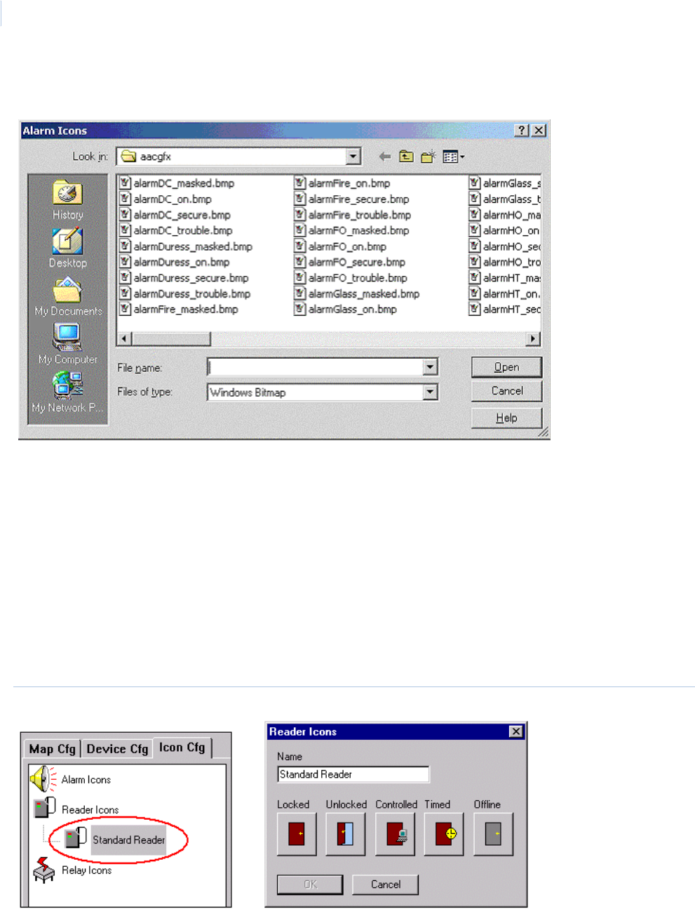
Topa z
User Manual
338
To select the icon for the designation, click one of the blank icon squares for the designation you
want to add and the following Look in window displays.
Locate the icon bitmap for the designation you clicked on and double-click the bitmap file name, to
add it to the designation icon you selected.
The icons are normally located in the aacgfx directory unless, when they were created, they were
saved to a different directory.
Click OK when you have completed adding the icons for all designations.
The new icon group is now added to the Icon Cfg tree list.
Modify Reader Icon Group
There is only one Standard Reader icon group, which has five designations: Locked, Unlocked,
controlled, timer, and offline.
Figure 235.Modify Reader Icon Group
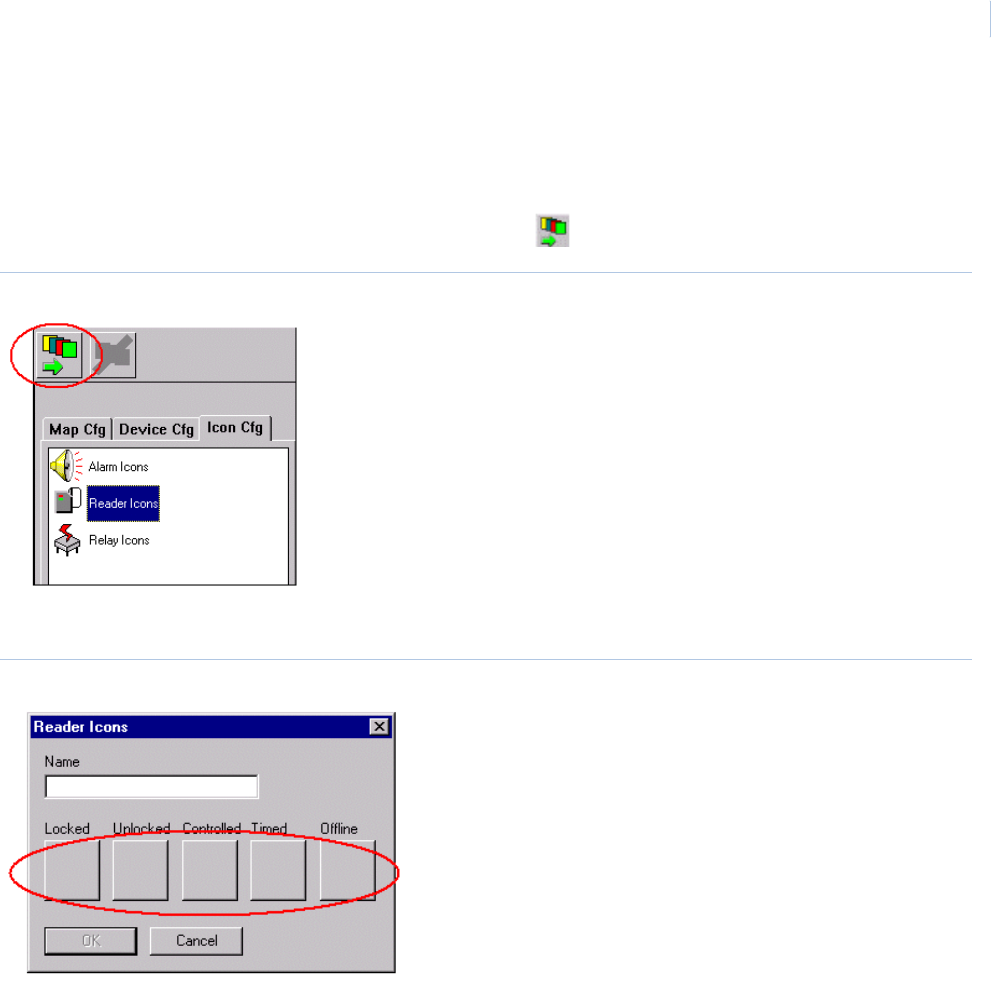
Chapter 11
Color Graphics Maps
339
Adding New Reader Icon Group
To add an additional Reader Icon Group, click the Icon Cfg tab and then click the Reader Icons
icon.
In the top left corner of the color graphics window click Add Icon Group.
Figure 236.Add New Reader Icon Group
A blank Icon Group window for readers is displayed
Figure 237.Blank Reader Icon Group window.
Enter a name for the new group and select the icon for the designations.
Click OK when you have completed adding the icons for all designations.
The new icon group is now added to the Icon Cfg tree list.
.
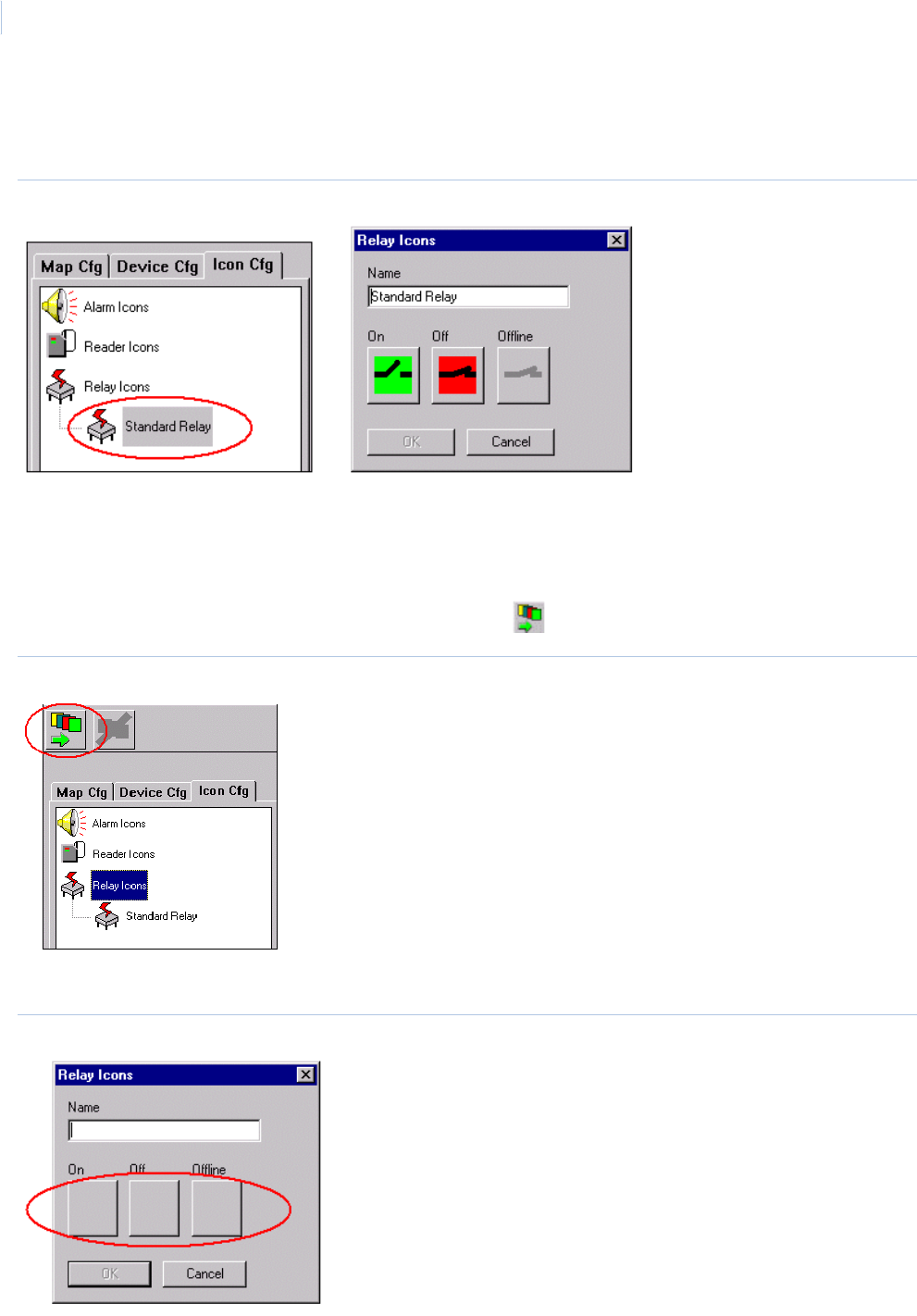
Topa z
User Manual
340
Modify Relay Icon Group
There is only one Standard Relay icon group, which has two designations, and offline.
Figure 238.Modify Relay Icon Group
.
Adding New Relay Icon Group
To add an additional relay group, click the Icon Cfg tab and then click the Relay Icons ICON.
In the top left corner of the color graphics window click Add Icon Group.
Figure 239.Add Relay Icon Group
A blank Icon Group window for relays is displayed.
Figure 240.Blank Relay Icon window
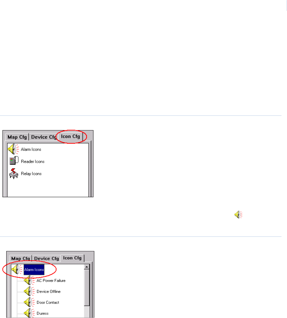
Chapter 11
Color Graphics Maps
341
Enter a name for the new group and select the icon for the designations.
Click OK when you have completed adding the icons for all designations.
The new icon group is now added to the Icon Cfg tree list.
.
Delete Icon Group
You must be in the configuration mode before you being. Once in the configuration mode, the Icon
Cfg tab displays in the tree window, as shown below. Only the Alarm, Reader, and Relay icons show
and are the only icons you can customize.
Figure 241.Delete Icon Group
Expand the Icon Cfg tree for the Icon you want to delete by double-clicking on the Alarm, Reader, or
Relay icon. For example, if you want to delete an alarm icon group, double-click the Alarm Icons
icon.
Figure 242.Alarm Icon Configuration
Click the Alarm Icon Group (category) you want to delete and the Icon Group window opens for the
group you clicked on. To select a different icon group, make a new selection by clicking again on
another icon group
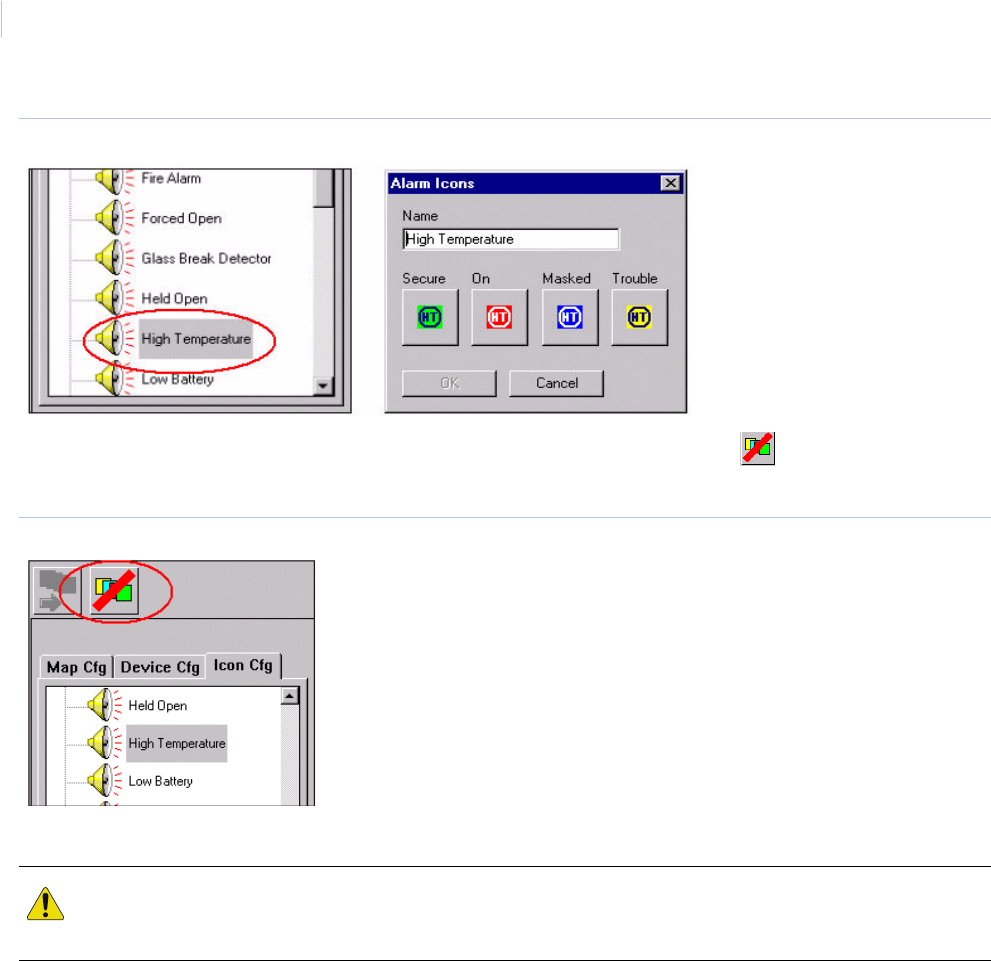
Topa z
User Manual
342
Figure 243.Icon Group.
After making sure the icon group you want to delete is displayed, click the Delete Icon Group
icon at the top left corner of the screen.
Figure 244.Delete Icon Group icon
The Icon Group is immediately deleted from the tree.
CAUTION: You cannot undelete an Icon Group that has been deleted!
When deleting an icon group make sure you have the desired group selected (highlighted) before clicking Delete
Icon Group. There is no warning before it is deleted.

This chapter provides an overview of software or user errors that can
occur with the Topaz System and the tools available to identify and correct
hardware problems. It also includes information on how to contact
technical support in case you need assistance with your equipment.
In this chapter:
Frequently Asked Questions . . . . . . . . . . . . . . . . . . . . . . . . . . 344
Topaz System Error Codes. . . . . . . . . . . . . . . . . . . . . . . . . . . . 347
Contacting technical support . . . . . . . . . . . . . . . . . . . . . . . . . . 358
Chapter 12 Troubleshooting, Maintenance,
Support

Topa z
User Manual
344
Frequently Asked Questions
When I try to install Topaz, I get “Port 80 in use”.
The Topaz program emulates a Web Server, so there cannot be another Web Server
running on the computer.
Examples of Web Server programs are Microsoft’s Personal Web Server, and Microsoft’s
Internet Information Server.
When I try to install Topaz, I get the error message “~0000 was not found.”
Check your c:\temp directory. Be default, Windows makes a temp directory on the C:
drive named temp. If this directory does not exist, you should make one.
When I double-click the Topaz icon I get the “Open With” dialog box to select a program to
run.
Press the Esc key to abort the process. Install Microsoft Internet Explorer 5.5 or later.
When I double-click the Topaz icon I get a White screen with “Action cancelled” on it.
This means the Internet Explorer cannot find the MP.exe server application.
• Insure Microsoft’s Internet Information Server (IIS) is not installed on this computer.
• Delete the file WORKSTATION.HTA in the Topaz folder, and then reload the Topaz
application.
Topaz does not start.
Make sure the user rights on the computer are set to Local Admin.
Before Topaz can run, you must make sure your computer is configured properly.
• The screen resolution must be set to 1024 * 768 and 65535 colors.
• The computer must have at least 768 MB of memory.
• TCP/IP must be installed, but not set for DHCP.
Check the TCP/IP configuration by pinging the IP address. For example, if the TCP/IP
address is 192.1.1.1, then go to a command prompt, and type: “PING 192.1.1.1”. You
should get “Reply from 192.1.1.1: bytes=32 time<10ms TTL=128”.
• In Windows Control Panel, click “Devices”. Make sure “AFD Networking Support
Environment” has “Status” set to “Started” and “Startup” is set to “Automatic”.
If the above settings are correct and the program still fails to start, look in the file
“scrout.txt” or “scrout01.txt”. These are error event files and contain error messages that
can give clues to the proper action.
I get the error message “Copy Protection Not Found”.
• Make sure the Software Sentinel is connected to the parallel or USB port.
Note: The USB software sentinel key is provided with the Topaz system when you order it. This dongle is
required for Topaz to work properly. If this is an upgrade, you may have a serial sentinel key. This will
work and does not need to be replaced with a USB dongle. It also does not need to be removed during
this process.
• If there is a printer connected, make sure the printer is “on-line”.

Chapter 12
Troubleshooting, Maintenance, Support
345
• Make sure you are logged on as the Administrator. If not, log in again as the Administrator
and reinstall Topaz.
When I start Topaz, I get a dialog box that asks about connecting to your Internet Service
Provider.
Go to the Windows Control Panel. Under Internet Options, on the Connections tab, under
“Dial-up setting”, select “Never dial a connection”.
My computer hangs. Either the keyboard or the mouse is not working.
Bring up the Windows Task Manager, either press Ctrl-Shift-Esc (or press Ctrl-Alt-Del and
select the Task Manager). End the following processes: mp.exe, mprun.exe, and
mshta.exe. Then try to run the program again.
When I run Auto Configuration, it did not find the device I have plugged into that COM port or
it does not detect any field panels.
The Topaz Auto Configuration is set at the factory to connect to the ACUs at 9600 baud. If
you have changed the ACU baud rate, reset it to 9600 baud. Then try Auto Configuration
again.
If that does not correct the problem, you may have a wiring error. Insure each field panel
is wired correctly, and each field panel has a unique polling address on the serial port.
Then try Auto Configuration again.
I get an error message that the workstation cannot connect.
Make sure the network cable is connected to your computer. If that does not fix the
problem, you may have a faulty network card. See your PC technician.
The Topaz shows the same screen even if I know it is wrong.
The Internet Explorer has ‘cached’ the screen.
Disable ‘caching’ by:
1. Double-click the Internet Explorer icon to open it.
2. Click Tools, Internet Options.
3. On the General Tab, click in Settings.
4. Click “Every visit to the page”.
5. Click “OK” to save.
I get script errors.
You must load Internet Explorer’s 6 from the Topaz CD. If you already have installed
Internet Explorer on your PC, you must re-install it from our CD and complete the Wizard.
I get system error messages.
Call UTC Fire & Security Technical Support: 888-437-3287.
I get the error message “EMERGENCY, REBUILD CARD FILE.”
Call UTC Fire & Security Technical Support: 888-437-3287.
I get a black picture when attempting to take a photo.

Topa z
User Manual
346
The Winnov video capture card may fail to register into NT, resulting in a black picture
when attempting to take a photo. If this occurs, click “Browse This CD”, then double-click
the “Video Capture” folder, then on the “Winnov” folder, and finally double-click the
VIDMP.REG icon.
I get the error “No Such Interface Supported” on some screens.
This can occur if one or more of the following files is missing, damaged, or improperly
registered. To resolve this problem in Internet Explorer, follow these steps:
1. Quit all programs that are running
2. Click Start, and then click Run
3. Type regsvr32 urlmon.dll, and then click OK
4. When you receive the DllRegisterServer in urlmon.dll succeeded message, click OK.
If this does not resolve the problem, repeat steps 2 through 4 for each of the following
files (in step 3, replace Urlmon.dll with each of the file names below):
Shdocvw.dll
Msjava.dll
Actxprxy.dll
Oleaut32.dll
Mshtml.dll
Browseui.dll
Shell32.dll (Windows XP and Windows 2000 only)
The following link to Microsoft Support can provide more information: http://support.microsoft.com/
default.aspx/kb/281679/EN-US/

Chapter 12
Troubleshooting, Maintenance, Support
347
Topaz System Error Codes
Error Description
0 No Error.
1 Invalid function number.
2 File not found. Retry the command using the file name.
3 Path not found. Retry the command using the correct path.
4 Too many open files (no handles left). Wait until another program has ended then retry this command.
5 Access denied. The file or disk is read only.
6 Incorrect internal file identifier.
7 The storage control blocks were destroyed.
8 There is not enough memory available to process this command.
9 The storage control block address is invalid.
10 The environment is incorrect.
11 An attempt was made to load a program with an incorrect format.
12 Invalid access code.
13 The data is invalid.
14 The system cannot find the specified disk drive.
16 The disk directory cannot be removed. Remove all files and sub-directories before deleting directory.
17 The file cannot be moved. You cannot move a file to a different drive.
18 No more files.
19 The disk drive is write-protected. Remove write-protect and retry command.
20 Cannot find disk drive specified.
21 Disk drive not ready. Make sure disk is installed and drive light is ready.
22 The device does not recognize the command.
23 Data Error. If the error occurred on the hard disk, retry the command. IF the error occurs again, the hard disk
may have to be reformatted. If the error occurred on a diskette, insert a formatted diskette and retry the
command.
24 The program issued a command but the length is incorrect.
25 Seek Error. The disk may be damaged, unformatted or not compatible.
26 The specified disk or diskette cannot be accessed. Format the disk.
27 Sector not found. The disk may be damaged, unformatted or not compatible.
28 The printer is out of paper or not enough disk space to create a spool file.
29 The system cannot write to the specified drive.

Topa z
User Manual
348
30 The system cannot read from the specified drive.
31 A device attached to the system is not functioning.
32 The file is already being used by another process.
33 The process cannot access the file because the file is locked by another process.
34 The wrong diskette is in drive.
35 The program could not open the requested file. The FCB limit was exceeded.
36 The system has detected an overflow in the sharing buffer.
37 The system cannot write to the write-protected drive.
38 An unknown device was specified.
39 The device is not ready.
40 The device does not recognize the command.
41 Data Error. If error occurred on the hard disk, retry the command. IF error occurs again, the hard disk may have
to be reformatted. If error occurred on a diskette, insert a formatted diskette and retry the command.
42 Invalid command length.
43 Seek Error. The disk may be damaged, unformatted or not compatible.
44 The specified disk or diskette cannot be accessed. Format the disk.
45 Sector not found. The disk may be damaged, unformatted or not compatible.
46 The printer is out of paper.
47 The system cannot write to the specified drive.
48 The system cannot read from the specified drive.
49 The device is not ready.
50 The network request is not supported.
51 The remote computer is not available.
52 A duplicated name exists on the network.
53 Network path not found.
54 The network is busy or is out of resources.
55 The specified network resource is no longer available.
56 The network BIOS command limit has been reached.
57 A network adapter hardware error occurred.
58 The specified server cannot perform the requested task.
59 An unexpected network error occurred.
60 The remote adapter is not compatible.
Error Description

Chapter 12
Troubleshooting, Maintenance, Support
349
61 The printer queue is full.
62 Space to store the file waiting to be printer is not available on the server.
63 Your file waiting to be printed was deleted.
64 The specified network name is no longer available.
65 Network access is denied.
66 The network resource type is not correct.
67 The network name cannot be found.
68 The name limit for the local computer network adapter card was exceeded.
69 The network BIOS session limit was exceeded.
70 The remote server has been paused or is in the process of being started.
71 No more connections can be made to this remote computer at this time because there are already as many
connections as the computer can accept.
72 The specified printer or disk device has been paused.
80 The file exists.
82 The directory or file cannot be created.
84 Storage to process this request is not available.
85 The local device name is already in use.
86 The specified network password is not correct.
87 The parameter is incorrect.
88 A write fault occurred on the network.
89 The system cannot start another process at this time.
106 Insert the diskette for drive %1.
107 The program stopped because an alternate diskette was not inserted.
108 The disk is in use or locked by another process.
110 The system cannot open the device or file specified.
111 The file name is too long.
112 There is not enough space on the disk.
113 No more internal file identifiers available.
114 The target internal file identifier is incorrect.
118 The verify-on-write switch parameter value is not correct.
119 The system does not support the command requested.
120 This function is not valid on this platform.
Error Description

Topa z
User Manual
350
121 The semaphore time-out period has expired.
122 The data area passed to a system call is too small.
123 File name or volume label contains invalid characters.
125 The disk has no volume label.
126 The specified module could not be found.
127 The specified procedure could not be found.
129 The %1 application cannot be run in Windows 2000 mode.
131 An attempt was made to move the file pointer before the beginning of the file.
132 The file pointer cannot be set on the specified device or file.
139 The system tried to substitute a drive to a directory on a substituted drive.
140 The system tried to join a drive to a directory on a substituted drive.
143 The system cannot join or substitute a drive to or for a directory on the same drive.
137 Not enough resources are available to process this command.
148 The path specified cannot be used at this time.
154 The volume label you entered exceeds the label character limit of the target file system.
155 Cannot create another thread.
161 The specified path is invalid.
162 A signal is already pending.
164 No more threads can be created in the system.
167 Unable to lock a region of a file.
170 The requested resource is in use.
180 The system detected a segment number that was not correct.
183 Cannot create a file when that file already exists.
189 The operating system cannot run %1.
191 Cannot run %1 in Windows 2000 code.
193 Is not a valid application.
196 The operating system cannot run this application program.
197 The operating system is not presently configured to run this application.
206 File name or extension is too long. DOS file names must be 8 characters or less. The file extension must be 3
characters or less.
212 The segment is locked and cannot be reallocated.
214 Too many dynamic-link modules are attached to this program or dynamic-link module.
Error Description

Chapter 12
Troubleshooting, Maintenance, Support
351
234 More data is available.
255 The extended attributes are inconsistent.
259 No more data is available.
266 The copy functions cannot be used.
267 The directory name is invalid.
332 The specific queue name is already in use. This can occur when attempting to start Topaz when the program is
already running.
334 Not enough memory available to process a queue request. The total queue memory was exceeded. If Topaz
was running contact technical support and relay the information.
1000 1#define Invalid Command (for Pecos Interface).
1001 Disk is full, data cannot be written.
1002 File Management System file channel already in use.
1003 File Management System data or parity error.
1004 Read or write hit beginning of file.
1005 Physical disk error occurred during file directory read or write.
1006 Disk file user count greater than one. Attempted operation requires exclusive use of disk file.
1007 Access violation. Attempted record operation for that file was not opened.
1008 Bad Command Code. Out of range command presented to the file system.
1009 Illegal logical channel number requested.
1010 Read or write reached end of file.
1011 Logical channel number requested not found.
1012 Not an ISAM file.
1013 File Reserved. Attempted to open a file that was opened exclusively.
1014 Device Reserved. Attempted to open a device that was opened exclusively.
1015 Bad Option parameter. An option was selected that was illegal.
1016 No such directory. Attempted to reference a file directory that does not exist.
1017 Bad File Name. Attempted to reference a file with an illegal file name.
1018 Duplicate file name. Attempted to create a file that already exists.
1019 File does not exist. Attempted to reference a file that does not exist.
1020 Drive does not exist. Attempted to reference a disk drive that does not exist or #define InvalidACU (for Pecos
Interface).
1021 Bad Access.
1022 File already exists.
Error Description

Topa z
User Manual
352
1024 Request number of bytes to read was not read.
1025 Request number of bytes to written was not written.
1026 Not enough disk space. Unable to allocate file. Disk is full.
1027 Not enough memory available to perform operation.
1028 Directory entry corrupted.
1029 ISAM key is corrupted.
1030 Unable to write record. File is full.
1031 Duplicate Key. Attempted to insert a key that already exists.
1032 Invalid Function.
1033 No file handles left.
1034 Close / Open.
1035 Access Denied.
1036 Bad handle.
1037 Bad memory.
1038 An internal error was detected in the file system.
1040 #define InvalidReader (for Pecos Interface).
1041 Illegal time unit value.
1042 Illegal coordination value.
1043 Illegal file open type code.
1044 Bad semaphore number.
1045 Attempted to open file with a logical channel number already open.
1046 Not enough memory available to open logical channel.
1047 Attempted to reference a logical channel number not defined.
1048 Maximum file descriptor ID number exceeded.
1049 Illegal FIS operation type code.
1050 Error freeing LIS memory block.
1051 Unbalanced double quotes found in a screen schema. SCRIO error value.
1052 Illegal screen commentaries by basic strings. SCRIO error values.
1053 Screen schema name not alphanumeric. SCRIO error values.
1054 Number of screen variables (tildes) does not equal number of fields. SCRIO error values.
1055 Screen field number duplicated in commentary. SCRIO error values.
1056 Screen field numbers too large. SCRIO error values.
Error Description

Chapter 12
Troubleshooting, Maintenance, Support
353
1057 Illegal screen field commentary. SCRIO error values.
1058 Screen field size missing in commentary. SCRIO error values.
1059 Screen field size too large in commentary. SCRIO error values.
1060 Screen field variable type missing in commentary. SCRIO error values or #define InvalidRelay (for Pecos
Interface).
1061 Screen field I/O type missing in commentary. SCRIO error values.
1062 Illegal screen field variable type in commentary. SCRIO error values.
1063 Illegal screen I/O type in commentary. SCRIO error values.
1064 Screen filter size incorrect. SCRIO error values.
1065 Screen variable initial data size incorrect. SCRIO error values.
1066 Screen variable pointer not on even boundary. SCRIO error values.
1067 Screen parameter value too large. SCRIO error values.
1068 Screen variable field not found. SCRIO error values.
1069 Screen prompt timed out. SCRIO error values.
1070 Number of schemas exceeded allocated memory. SCRIO error values.
1071 Illegal command in vm->vtmcmd. SCRIO error values.
1072 Illegal parameter in command. SCRIO error values.
1073 Number of screen I/O parameter too large. SCRIO error values.
1074 Screen field name missing in commentary. SCRIO error values.
1075 No user mailbox defined for screen I/O return mailbox. SCRIO error values.
1076 No screen I/O destination mailbox defined. SCRIO error values.
1077 Requested logical device not assigned to unit. SCRIO error values.
1078 Requested screen window not defined. SCRIO error values.
1079 Requested device type not defined. SCRIO error values.
1080 Requested schema file not found. SCRIO error values or #define InvalidAlmZn (for Pecos Interface).
1081 No channel access ID. Requested Disk I/O channel not defined.
1082 Write lock without read lock. Attempted write without locking read.
1083 Ends of read file or write continue.
1084 End of file reached for read or write.
1085 Illegal record operation type request.
1086 Illegal record operation relational type request.
1087 ISAM read does not find record. A remote control point, monitor point or access point was deleted, but was not
deleted in the automatic operation first. Delete record from automatic operation to correct error.
Error Description

Topa z
User Manual
354
1088 Illegal file category type.
1089 Illegal file type.
1090 ISAM index file key does not match data file. ISAM file is corrupted.
1091 Illegal CAA field in LIS header detected.
1092 Illegal SDA field in LIS file system control block address (Ifssda).
1093 Corrupted FIS file header detected.
1094 File system could not allocate a semaphore.
1095 Attempted record lock of record already locked by another user. Another user is modifying this record. Only one
user can modify a record at a time.
1096 Illegal record operation code.
1097 Redundant write sector to be unlocked not locked.
1098 Redundant write sector to be locked already locked.
1099 Disk driver parameter out of range.
1100 Disk driver operation timed out before completion or #define InvalidSubCmd (for Pecos Interface).
1101 Attempted insert new key but key found.
1170 Thread not found.
1071 Queue error.
1172 Bad downloaded event type or command.
1173 Received SCP msg. from device not being downloaded.
1174 Bad download state variable.
1175 Bad access event type or command.
1176 Requested bytes to write did not write.
1177 Attempted to log out of range event type.
1178 Invalid Mailbox number.
1179 No buffer found after receive buffer semaphore signaled.
1180 Nomem on push.
1181 No buffer on pop but should be.
1200 The DOS environment cannot be created.
1256 Attempted to reference district number of a task but it was not defined. Can mean a printer is not defined.
1257 Attempted to modify or delete a port that does not exist. Example: The system attempts to send a message to
the Dual System Controller if the "Redundant System" program is enabled.
1258 Attempted to define a port that already exists.
1259 Error opening port.
Error Description

Chapter 12
Troubleshooting, Maintenance, Support
355
1260 Out of Anti-Passback Indexes. Use the Employee Database Diagnostic program to rebuild Anti-Passback
index.
1261 Out of range APB index. Use the Employee Database Diagnostic program to rebuild Anti-Passback index.
1262 Software Sentinel not found. Topaz requires a software sentinel (dongle) to run. Please contact a UTC Fire &
Security Representative.
1263 Unknown Redundant System restore command.
1264 Unknown Redundant System poll command.
1265 Time-out for restore response.
1320 The district attempted to log onto the File server, but the District is already on-line.
1321 An unknown district attempt to log onto the File server.
1322 The district (workstation) is disconnected.
1323 TOO MUCH DATA.
1324 HUH.
1325 BAD LOGIN Check the Date and Time on both Fileserver and workstation computers.
1326 BAD DISTRICT NUM.
1327 BAD MEM ID.
1328 BAD POOL ID.
1329 BFR end written over.
1330 Bogus free bfr check.
1331 BADALMCMD.
1332 Bad Download Command.
1333 Bad District Download Command.
1334 Bad MP Server Command.
1335 Bad application Request Command.
1336 MP Server Number Out of Range.
1337 Server Shutdown.
1338 Not Dial-up.
1339 Bad Color Graphics directory.
1340 Bad District Download Color Graphics Command.
1341 Bad Color Graphics’ Districts.
1342 Bad District Download Color Graphics File Command.
1343 Bad District Download Color Graphics Change of State Command.
1344 Bad District Download Color Graphics File District.
Error Description

Topa z
User Manual
356
1392 The file or directory is corrupted and non-readable.
1393 The disk is corrupted and non-readable.
1394 There is no user session key for the specified logon session.
1395 The service being accessed is licensed for a particular number of connections. No more connections can be
made to the service at this time because there are already as many connections as the service can accept.
6000 TCP/IP Connection not open.
6001 TCP/IP No more Connections available.
6002 TCP/IP District logged attempted login to district already on-line.
6003 TCP/IP Invalid sign-on message.
6004 TCP/IP Invalid message header.
6005 TCP/IP Invalid Message length.
6006 TCP/IP Invalid receive state.
6007 TCP/IP Invalid transmit state.
6008 TCP/IP Out of mailboxes.
6009 TCP/IP Invalid mailbox.
6010 TCP/IP Thread not found for RSVP message.
9020 Distributed Applications - The specified handle does not represent a valid open connection. Use the value
returned from a successful DAOpen.
10001 TCP/IP Not owner.
10003 TCP/IP No such process.
10004 TCP/IP Interrupted system call.
10006 TCP/IP No such device or address.
10009 TCP/IP Bad file number.
10013 TCP/IP Permission denied.
10014 TCP/IP Bad address.
10015 The ACU uploaded an event with an invalid date. The ONE-32 MP has now assigned the event today's date
with a time of 00:00:00.
10022 TCP/IP Invalid argument.
10024 TCP/IP Too many open files.
10035 TCP/IP Operation would block.
10036 TCP/IP Operation now in progress.
10037 TCP/IP Operation already in progress.
10038 TCP/IP Socket operation on non-socket.
Error Description

Chapter 12
Troubleshooting, Maintenance, Support
357
10039 TCP/IP Destination address required.
10040 TCP/IP Message too long.
10041 TCP/IP Protocol wrong type for socket.
10042 TCP/IP Protocol not available.
10043 TCP/IP Protocol not supported.
10044 TCP/IP Socket type not supported.
10045 TCP/IP Operation not supported on socket.
10046 TCP/IP Protocol family not supported.
10047 TCP/IP Address family not supported by protocol family.
10048 TCP/IP Address already in use.
10049 TCP/IP Can't assign requested address.
10050 TCP/IP Network is down.
10051 TCP/IP Network is unreachable.
10052 TCP/IP Network dropped connection on reset.
10053 TCP/IP Software caused connection abort.
10054 TCP/IP Connection reset by peer.
10055 TCP/IP No buffer space available.
10056 TCP/IP Socket is already connected.
10057 TCP/IP Socket is not connected.
10058 TCP/IP Can't send after socket shutdown.
10059 TCP/IP Too many references: can't splice.
10060 TCP/IP Connection timed out.
10061 TCP/IP Connection refused.
10062 TCP/IP Too many levels of symbolic links.
10063 TCP/IP File name too long.
10064 TCP/IP Host is down.
10065 TCP/IP No route to host.
10066 TCP/IP Directory not empty.
Error Description

Topa z
User Manual
358
Contacting Technical Support
For assistance installing, operating, maintaining, and troubleshooting this product, refer to this
document and any other documentation provided. If you still have questions, you may contact
technical support and/or pre-sales.
For pre-sales and technical support assistance, we provide customers with several options (see
Table 19). Our support phone number is available Monday through Friday, 8 a.m. to 7 p.m. Eastern
Time. Protection plans are available for extended coverage.
Note: Be ready at the equipment before calling for technical support.
Table 19. Pre-sales and support contact information
Pre-sales Technical support
Phone: 1 800 428 2733 1 888 437 3287
Fax: 561 998 6160 503 691 7568
E-mail: None rs-bctsupport@fs.utc.com


Topa z
User Manual
360
Access Code Definitions
TRACE BY ACCESS POINT
Trace has been turned on at an Access Point (card reader and/or keypad). Every access
attempt at the traced access point will generate this event.
TRACE BY CARDHOLDER
Trace has been turned on for a cardholder. Every access attempt by that cardholder will
generate this event.
TRACE BY SECURITY AREA
Trace has been turned on for a Security Area. Every access attempt at the Security Area
will generate this event.
ACCESS AUTHORIZED
A cardholder has presented a valid card and/or PIN and access was authorized.
ACCESS AUTHORIZED - ANTI-PASSBACK VIOLATION
A cardholder has presented a valid card and/or PIN and access was authorized, but the
cardholder was violating APB.
ACCESS AUTHORIZED - LOCAL READER RE-ENTRY TIMER VIOLATION
A cardholder has presented a valid card and/or PIN and access was authorized, but the
cardholder tried to use the same reader before the Anti-Passback “Timer Delay for Re-
entry” had passed.
ACCESS AUTHORIZED - LOCAL SA RE-ENTRY TIMER VIOLATION
A cardholder has presented a valid card and/or PIN and access was authorized, but the
cardholder tried to enter or leave the same security area before the Anti-Passback “Timer
Delay for Re-entry” had passed.
ACCESS AUTHORIZED - TAILGATE VIOLATION
The cardholder has presented a valid card and/or PIN and access was authorized, but the
cardholder was Tailgating.
ACCESS AUTHORIZED - AREA UNSECURED (ALARMS MASKED)
Access was Authorized and the Alarms Masked (Unsecured)

361
ACCESS AUTHORIZED - DELAYED ALARM UNMASKING STARTED
The cardholder has presented a valid card and PIN to Unmask the area and request was
authorized and the alarm delay timer was started allowing the cardholder time to exit the
area without set off the alarm.
ACCESS AUTHORIZED - ENTRY GRANTED TO MASK ALARMS
The cardholder has presented a valid card and PIN to Mask and enter the area. The
request was authorized and the alarms were Mask.
ACCESS AUTHORIZED - EXIT PUSH BUTTON
This is to notify you that someone has exited the area using the Exit Push Button.
Because it was the Push Button, the system cannot give a Cardholder Name. This event is
only available on the ACU-2 Card Reader.
ACCESS AUTHORIZED - FACILITY CODE
Access was granted based only on the Correct Company code and Facility code on the
card. Access on Facility code is set up in Reader Configuration.
ACCESS AUTHORIZED - FLOOR OK
Access was granted through a Card Reader set up for Elevator Control. This access event
code is only used by Local Elevator Control in the ACU-2 or dpC.
ACCESS AUTHORIZED - DURESS
Access was granted because this cardholder is under Duress. Access on Duress is user
configurable under the Site Configuration Menu.
ACCESS DENIED - ACCESS POINT NOT DEFINED
Access was denied because the reader is not defined.
ACCESS DENIED - ACTIVE ALARMS
A cardholder has presented a valid card and PIN to enter the area, but entry was denied
because the area alarms have not been Mask.
ACCESS DENIED - ANTI-PASSBACK VIOLATION
Access was denied because the cardholder has already used his/her card to enter the
security area without an intervening exit from the security area.

Topa z
User Manual
362
ACCESS DENIED - AREA SECURED, I.E., ALARMS ARE UNMASKED
Access was denied because the Security Area going into is Secured (Alarms are
Unmask). If you do not want this event, enter “No” to “Keypad Masking Allowed” in the
Security Area configuration.
ACCESS DENIED - BAD CARD READ OR FORMAT
Access was denied because the card reader did not get a good card read.
ACCESS DENIED - CARD EXPIRED
Access was denied because the Deactivation Date in the Cardholder's Database has
expired.
ACCESS DENIED - CARD INACTIVE
A cardholder has presented a card requesting access to the area, but access was denied
because the card is inactive.
ACCESS DENIED - CARD NOT ACTIVATED
Access was denied because the Activation Date in the Cardholder's Database is not active
yet.
ACCESS DENIED - CARD NOT DEFINED
Access was denied because this card's encoded number is not defined in the
Cardholder's Data Base. The encoded card number is the number shown is the event
message.
ACCESS DENIED - CARD TERMINATED
A cardholder has presented a card requesting access to the area, but access was denied
because the card has been set to terminated in the cardholder's record.
ACCESS DENIED - DISK ERROR
Access was denied because of a disk error. Call your Distributor or UTC Fire & Security
Representative.
ACCESS DENIED - DURESS
Access was denied because this cardholder is under Duress. Access on Duress is user
configurable under the Site Configuration Menu.

363
ACCESS DENIED - ESCORT REQUIRED
A cardholder has presented a card requesting access to the area, but access was denied
because the cardholder is required to have an escort.
ACCESS DENIED - HOST COMMUNICATION LOSS
This event code only appears in the uploaded events file. Access was denied because the
SCP Device was offline for an access request that had to go to the Host. Example, Keypad
Masking requires host processing.
ACCESS DENIED - INVALID FLOOR NUMBER
Elevator Access was denied because the cardholder entered a floor number that the
cardholder is not authorized for.
ACCESS DENIED - INVALID ISSUE CODE
Access was denied because the Issue Code in the Cardholder Database is not what
encoded on the card.
ACCESS DENIED - LOCAL ANTI-PASSBACK VIOLATION
Access was denied locally in the ACU-2 because the cardholder has already used his/her
card to enter the security area without an intervening exit from the security area.
ACCESS DENIED - LOCAL SA RE-ENTRY TIMER VIOLATION
Access was denied locally in the ACU-2 because the cardholder requested access within
the Re-entry time as defined in the Security Area Configuration.
ACCESS DENIED - LOCAL TAILGATE VIOLATION
Access was denied locally in the ACU-2 because the cardholder has already used his/her
card to exit the security area without an intervening entrance to the security area.
ACCESS DENIED - SCP DEVICE ERROR
Elevator Access was denied because an SCP device was offline or deactivated.
ACCESS DENIED - SECURITY AREA NOT DEFINED
Access was denied because the security is not defined. You may get this event if the
Database has not been fully downloaded to the remote panel.
ACCESS DENIED - TAILGATE VIOLATION
Access was denied because the cardholder has already used his/her card to exit the
security area without an intervening entrance to the security area.

Topa z
User Manual
364
ACCESS DENIED - TIME ZONE NOT DEFINED
Access was denied because the time zone is not defined. You may get this event if the
Database has not been fully downloaded to the remote panel.
ACCESS DENIED - USING LOST CARD
Access was denied because the Card Status in the Cardholder Database is set to “Lost”.
ACCESS DENIED - USING STOLEN CARD
Access was denied because the Card Status in the Cardholder Database is set to “Stolen”.
ACCESS DENIED - WRONG AREA
Access was denied because this cardholder requested access into a security area not
assigned to the card.
ACCESS DENIED - WRONG COMPANY CODE
Access was denied because this card's encoded Company Code is not the same as
configured in the Site Configuration.
ACCESS DENIED - WRONG FACILITY CODE
Access was denied because the facility code encoded on the card does not match the
facility code in the Site configuration.
ACCESS DENIED - WRONG KEYPAD NUMBER
Access was denied because this cardholder entered the wrong Keypad Number (PIN) at a
keypad Reader.
ACCESS DENIED - WRONG KEYPAD… TOO MANY ATTEMPTS
This is a special event to notify you this card has exceeded the number of Wrong Keypad
attempts.
ACCESS DENIED - WRONG TIME
Access was denied because this cardholder requested access during the wrong time. The
time (configured in Time Zones) is configured is assigned each security area and there is
also a time zone on each reader.
ACCESS ON COMPANY CODE .. CORRECT FACILITY CODE
Access was granted based only on the Correct Company Code on the card. Access on
Company code is set up in Reader Configuration. This card had the Same Facility
encoded on the card as stored in the Site Configuration.

365
ACCESS ON COMPANY CODE .. CORRECT FACILITY CODE (MANTRAP)
Access was granted based only on the Correct Company Code on the card. Access on
Company code and Mantrap are both set up in Reader Configuration. This card had the
Same Facility encoded on the card as stored in the Site Configuration.
ACCESS ON COMPANY CODE .. WRONG FACILITY CODE
Access was granted based only on the Correct Company Code on the card. Access on
Company code is set up in Reader Configuration. This card had the Wrong Facility
encoded on the card as stored in the Site Configuration.
ACCESS ON COMPANY CODE .. WRONG FACILITY CODE (MANTRAP)
Access was granted based only on the Correct Company Code on the card. Access on
Company code and Mantrap are both set up in Reader Configuration. This card had the
Wrong Facility encoded on the card as stored in the Site Configuration.
AREA SECURE (ALARMS UNMASKED)
Request to Secure (Unmask) the Security Area was granted.
DENIED SECURE (UNMASKING) REQUEST - ACTIVE ALARM
The request to Secured (Unmask) the security area was denied because there is an active
alarm within the security area. The alarm point displays in the event message.
DENIED SECURE (UNMASKING) REQUEST - CONFIGURATION ERROR
The request to Secured (Unmask) the security area was denied because a configuration
error. Example, no alarms in the security area.
DENIED SECURE (UNMASKING) REQUEST - DEVICE ERROR
The request to Secured (Unmask) the security area was denied because a device for the
security area is offline or deactivated.
DENIED SECURE (UNMASKING) REQUEST - UNAUTHORIZED AREA
The request to Secured (Unmask) the security area was denied because the cardholder is
not authorized for Keypad Alarm Masking on this area.
DENIED TWO-MAN ALARM MASKING REQUEST - TIMEOUT
The request to Mask the security area was denied because the security is under control of
Two-Man Masking, and the Host operator must initiate masking on the area.

Topa z
User Manual
366
DENIED TWO-MAN ALARM UNMASKING REQUEST - TIMEOUT
The request to Unmask the security area was denied because the security is under control
of Two-Man Masking, and the Host operator must initiate unmasking on the area.
DENIED UN-SECURE (MASKING) REQUEST - DEVICE ERROR
The request to Unsecured (Mask) the security area was denied because a device for the
security area is offline or deactivated.
DENIED UN-SECURE (MASKING) REQUEST - TMC SEQUENCE ERROR
The request to Unsecured (Mask) the security area was denied because the first
cardholder of a Two-Man Control Area tried to Secure / Un-secure the area.
DENIED UN-SECURE (MASKING) REQUEST - UNAUTHORIZED AREA
The request to Unsecured (Mask) the security area was denied because the cardholder is
not authorized for Keypad Alarm Masking on this area.
DENIED UN-SECURE (MASKING) REQUEST - CONFIGURATION ERROR
The request to Unsecured (Mask) the security area was denied because a configuration
error. Example, no alarms in the security area.
TOO MANY ACCESS REQUESTS DENIED
This is a special event code to tell you this cardholder has exceeded the number of
Access Denies in a given time as configured in Access Request Deny Monitor program.
END OF LIST


Topa z
User Manual
368
Card Field Definitions
Functional Field
Name
Protocol Field
Name Type of Value Description
Access Group 1
through Access
Group 8
ACCGRP 1 to
ACCGRP 8
Numeric This field is NOT recommended as a field filter. These
fields hold the numeric ID of an Access Group assigned
to a cardholder. The numbers are stored in the order in
which they are assigned to the Cardholder. (ACCGRP1
holds the ID of the first Access Group assigned to a card
holder. ACCGRP2 holds the second Access Group
Assigned to a card holder. etc.) These fields are not
recommended for use as filters because access groups
are not usually assigned to cardholders in a consistent
way. ACCGRP1 could contain any or all Access Group
IDs. Thus filtering by ACCGRP1 would be meaningless.
For example: If the Building 1 Access Group was
assigned to half of the cardholders as the first Access
Group (ACCGRP1) and it was assigned to the other half
of the cardholders as the second Access Group
(ACCGRP2), using ACCGRP1 as a filter would only
return half of the cardholders who have Building 1
assigned to them.
Anti-Passback
Index
APBINDEX Numeric The anti-passback index is a unique number assigned to
each card holder. It defines the location within the anti-
passback table that records the current location of that
cardholder. This field is of little value as a filter since it
does not tell the current location of the cardholder, but
only the location in the system where that information is
currently stored.
Card Activation
Date
ACT DATE Numeric
Delineated with
slash marks.
YYYYMMDD
This field defines the date a card is to automatically
become activated. Access is denied before this date.
‘YYYY’ represents the four digits of the year. Examples:
1995 or 2004.
‘MM’ is a two-digit number representing the year (01
through 12).
‘DD’ is a two-digit number representing the day of the
month (01 through 31).
The system defaults at the date the card is assigned.
Card Number CARD# Customized
Numeric
A unique decimal number from 000000000-999999999.
This is a significant field, and is the actual number
encoded on the access card along with the Company and
Facility Codes.
Each cardholder must be assigned a unique card number
which is nine digits long. If assigned number is less than
nine digits, use leading zeros (0) to complete the nine
digit format.
The format of this field is compcode-facilitycode-
cardnumber
Example: 1234-1234-1234567890.

369
Cardholder’s
Name
CARDNAME Alphanumeric Up to 32 characters.
This data usually contains the name.
Card Serial
Number
CARDSN Numeric 1 to 8 digits.
This is a reference field, and does not affect access
control operation. The number represents a card’s serial
number, and is typically printed on the card.
This is not to be confused with the actual encoded card
number (described above).
Card De-activation
Date
DACTDATE Numeric (Date)
Delineated with
slash marks.
YYMMDD
This field defines the date a card is to automatically
become de-activated. Access is denied after this date.
‘YY’ represents the last two digits of the year. For
example: 1997 would be entered as 97.
‘MM’ is a two-digit number representing the year (01
through 12).
‘DD’ is a two-digit number representing the day of the
month (01 through 31).
The system defaults at twenty years from the date when
the card was assigned.
Department DEPT Alphanumeric This is the value that was entered in the Department field
of the cardholder information screen.
Emergency
Contact Name
EMERNAME Alphanumeric Up to 32 characters.
This is a reference field for the name of a cardholder’s
primary contact in the event of an emergency, and may
be used at the option of the system owner.
Emergency
Contact’s
Telephone Number
EMERTELE Numeric Up to 12 characters.
Data for this reference field is transmitted with contiguous
numbers. For example, if the telephone number is (703)
555-1212, data is transmitted as: 7035551212
Employee Number EMPNO Numeric This is the Employee Number which is entered on the
Setup screen.
Issue Date ISSUEDAT Numeric YYMMDD
This reference field is used to record the date of when a
card is issued to a visitors
‘YY’ represents the last two digits of the year. For
example: 1995 would be entered as 95.
‘MM’ is a two-digit number representing the year (01
through 12).
‘DD’ is a two-digit number representing the day of the
month (01 through 31).
Use of this field is optional.
Functional Field
Name
Protocol Field
Name Type of Value Description

Topa z
User Manual
370
Issue Number ISSUENUM Numeric 1 digit. The default is 0.
An Issue Number permits the same card to be re-issued
in the event that a card is lost or stolen. The new card is
issued with the same card number, but, the issue number
increments by one. The missing card will not work in the
system since the issue numbers do not match.
Issue number is applicable to magnetic stripe cards,
which are encoded accordingly.
If UAS option, may be 2 digits.
Keypad Number KEYPAD Numeric 1 to 6 digits.
This is the number entered by an employee at a reader. A
keypad number must be assigned if the employee is to
use a keypad reader.
The default value for this field is 000000
Date Card was last
modified
LASTUPDT Date Display only.
This field shows the date the card was modified.
Cardholder Type ONLAFLAG Numeric This is a numeric value which indicates the type of
cardholder. A one (1) in this field indicates that the
cardholder is an employee, a nine (9) in this field
indicates that the cardholder is a visitor.
Authorized
Privileges
ONLFLAGS Numeric This field contains a value which is the sum of all optional
privileges assigned to this cardholder. For example, if this
field contains a one, the cardholder is authorized to
perform guard tours. If the cardholder is authorized for
other privileges, the numerical value of those privileges is
added to the guard tour value of One and the resulting
sum is stored in this field.
Organization
Number
ORG Alphanumeric Up to 4 characters.
This is a reference field that may be used at the option of
the system owner.
Does Cardholder
Photo Exist
PHOTOEXISTS Alphanumeric Yes or No
This field returns a Yes if a photo exist in the cardholder
record.
Photo file name PHOTOID Binary Up to 8 characters.
This field shows the photo file name for the cardholder.
Emergency
Contact
Relationship
RELATION Alphanumeric Up to 16 characters.
This is a reference field that may be used at the option of
the system owner.
Functional Field
Name
Protocol Field
Name Type of Value Description

371
Security Area #1-8 SA 1 to SA 8 Alphanumeric Up to 12 characters.
This optional field specifies the name of a Security Area
that the cardholder may access. There can be eight
Security Areas
Additional Security Areas are assigned to a cardholder
when there are access privileges required that are
different than those already assigned.
Time Zone for
Security Area #1-8
SA 1 TZ
to
SA 8 TZ
Numeric Up to 3 characters.
This field specifies the Time Zone number that applies to
a Security Area assigned to a cardholder.
Social Security
Number
SSN Numeric 9 characters.
Data for this reference field is transmitted with contiguous
numbers. For example, if the Social Security Number is
555-12-3456, data is transmitted as: 555123456
Card Status STATUS Numeric 1 Digit. Enter one of the following values for each card:
VALUE: DESCRIPTION:
0 OK: This is the default.
1 Lost: Access is denied.
2 Stolen: Access is denied.
3 Inactive
4 Terminated
Supervisor’s
Name
SUPRVISR Alphanumeric Up to 32 characters.
This is a reference field that may be used at the option of
the system owner.
Cardholder’s
Telephone
Extension
TELEPHON Numeric Up to 6 characters.
This is a reference field that may be used at the option of
the system owner.
The default is 000000.
Badge Template TEMPLATE Alphanumeric Up to 8 characters.
This field defines the Photo badge template file name
Trace District TR DIST
Trace Time Zone TRACE TZ Numeric Up to 3 characters.
If 0 (zero) is entered, this feature is not active.
This field specifies during which Time Zone a
cardholder’s card activity is to be traced. The Time Zone
number is entered.
User Defined Field
#1 through User
Defined Field 4
USERFLD1 to
USERFLD4
Alphanumeric Up to 24 characters.
User defined fields can be set up by the operator for use
in storing additional reference information on
cardholders. This is usually a type of information that is
unique to the site or facility.
Functional Field
Name
Protocol Field
Name Type of Value Description

Topa z
User Manual
372
User Defined Field
#5 through User
Defined Field 8
USERFLD5 to
USERFLD8
Alphanumeric Up to 16 characters.
User defined fields can be set up by the operator for use
in storing additional reference information on
cardholders. This is usually a type of information that is
unique to the site or facility.
User Defined Field
#9
USERFLD9 Alphanumeric Up to 12 characters.
User defined fields can be set up by the operator for use
in storing additional reference information on
cardholders. This is usually a type of information that is
unique to the site or facility.
User Defined Field
A through User
Defined Field B
USERFLDA and
USERFLDB
Alphanumeric Up to 12 characters.
User defined fields can be set up by the operator for use
in storing additional reference information on
cardholders. This is usually a type of information that is
unique to the site or facility.
Vehicle 1 ID or
License Number
VEH 1 ID Alphanumeric Up to 10 characters.
This is a reference field for a cardholder’s primary vehicle
ID or license number, and may be used at the option of
the system owner.
Vehicle 2 ID or
License Number
VEH 2 ID Alphanumeric Up to 10 characters.
This is a reference field for a cardholder’s second vehicle
ID or license number, and may be used at the option of
the system owner.
Functional Field
Name
Protocol Field
Name Type of Value Description

This appendix details the Anti-Passback feature of Topaz that prevents a
cardholder from passing their card back to another person to access the
same area.
In this appendix:
Anti-Passback Overview. . . . . . . . . . . . . . . . . . . . . . . . . . . . . . 374
Setup – Site Settings . . . . . . . . . . . . . . . . . . . . . . . . . . . . . . . . 374
Setup – Security Area. . . . . . . . . . . . . . . . . . . . . . . . . . . . . . . . 374
Control – Reset APB . . . . . . . . . . . . . . . . . . . . . . . . . . . . . . . . 375
Appendix C Anti-Passback

Topa z
User Manual
374
Anti-Passback Overview
Anti-Passback (also referred to as APB) is a feature that prevents a cardholder from passing their
card back to another person to access the same area. Topaz offers Timed APB only. For example,
with a turnstile where after entry the cardholder can pass their card back through the bars to another.
The access is denied until the time has expired after the first use.
Anti-Passback must be Enabled for a site.
The Topaz uses Timed Anti-Passback by security area. Only one card is required. With timed anti-
passback a time (in minutes) is assigned to the security area. Once the card is read, there after
access is denied to that area until the time on the card has expired. The timer immediately expires on
the card upon a valid card read by any other reader on the same field panel.
The following screens and fields affect Anti-Passback:
Setup – Site Settings
Anti-Passback
If you select Disabled (default), the Anti-Passback feature will not be used by Topaz.
If you select Enabled, the Anti-Passback feature will be used by Topaz, and you are presented with
the choice for Grant Access on APB Violation.
Grant Access on APB Violation
If unchecked (default), then any card swipe that activates an APB violation will deny access for that
cardholder and will trigger an alarm violation event. The alarm event will notify the security operator,
who may want to send somebody to that security area.
If checked, then any card swipe that activates an APB violation will allow access for that cardholder
but will trigger an access event. This is not normally used, but may be helpful for testing Topaz.
Setup – Security Area
Timed Delay for Reentry
If Anti-Passback is being used in the security area, then you can select the delay in minutes before
the cardholder will be allowed to access the area again after access has been granted. The minutes
must be positive whole numbers, not fractions.
This is used to discourage passing a card back to another person to follow you into a security area
with only one reader, such as a parking lot or turnstile. Once a card is used on that reader, any
attempt to use the same card before that time expires will generate an APB violation alarm and
access will be denied until the total time has expired.

375
If the same card is used on another reader, the time interval for this reader is reset to zero. For
example, if the cardholder swipes the card while in that security area to go to another area.
APB Control In Area
If unchecked (default), this Security Area does not use Anti-Passback.
If checked, this Security Area responds to APB violations with an alarm event. If checked, you are
presented with the choice for Timed Delay for Reentry (in minutes).
Card – Access
Executive APB Override
This field will only apply if Anti-Passback is first enabled under Setup, Site Settings. You can do this
immediately by clicking the link arrow to the left side of Executive APB Override to go directly to the
Site Settings page. Under Anti-Passback, you can select Enable to activate the Anti-Passback
feature for this site.
In addition, you must select cardholders and security areas under Control, Reset APB.
There are two options for Executive APB Override
•Deny Access (the default) - If APB is violated, the system will deny access to the area. This
is the normal selection for most cardholders. Otherwise, Anti-Passback has little value.
•Grant Access - Even If APB is violated, the system will allow access to the area. This is used
to allow the cardholder to enter all security areas and will trigger an alarm.
Control – Reset APB
Reset All Cardholders to a Security Area
This is used to allow cardholders who have access to the specified Security Area to be allowed to
enter that area even if the system has a record of their entering but not leaving that area.
For example, if all cardholders who are in a specified Security Area leave quickly because of a fire
and do not swipe their cards individually upon exiting or entering, the Topaz system thinks they are
still in that area. This feature allows the security staff to reset that Security Area to allow reentry for all
cardholders who have access to that area.
Reset Selected Cardholder to Security Area
This is used to allow the specified cardholder who has access to the specified Security Area to be
allowed to enter that area even if the system has a record of the cardholder entering but not leaving
that area.
For example, if a cardholder who is in a specified Security Area, left the area by tailgating behind
another cardholder and did not swipe the card upon entering or exiting. The Topaz system thinks the

Topa z
User Manual
376
cardholder is still in that area. This allows the security staff to reset that Security Area to allow reentry
for that one cardholder only.

This appendix provides tables detailing addressing information for alarm
inputs and relays.
In this appendix:
Alarm Input Numbers . . . . . . . . . . . . . . . . . . . . . . . . . . . . . . . . 378
Relay Numbers. . . . . . . . . . . . . . . . . . . . . . . . . . . . . . . . . . . . . 380
Appendix D Alarm Input and Relay
Numbers
Topa z
User Manual
378
Alarm Input Numbers
Reader Physical Alarm Zone Numbers
* Zone-0 is default for Door Contact.
* Zone-1 is default for Exit Push Button.
Reader Logical Alarm Zone Numbers
Lock Monitor / Bond Sensor = If used, must be connected to Z2.
F.O. = Forced open, H.O. = Held Open,
R.T. = Reader Enclosure Tamper, OFFL = Reader Off Line
Physical Alarm Zone
Reader Address * Zone 0 Door Contact * Zone 1 Request to Exit (REX) Zone 2 Spare
016 17 18
120 21 22
224 25 26
328 29 30
Logical Alarm Zone
Reader Address Lock Monitor F.O. H.O. R.T. OFFL
0 48 64656667
1 50 68697071
2 52 72737475
3 54 76777879

379
RIM Zone Input Numbers
Expansion Port
Zone Number Address 4 Address 5 Address 6 Address 7
IN1 128 144 160 176
IN2 129 145 161 177
IN3 130 146 162 178
IN4 131 147 163 179
IN5 132 148 164 180
IN6 133 149 165 181
IN7 134 150 166 182
IN8 135 151 167 183
IN9 136 152 168 184
IN10 137 153 169 185
IN11 138 154 170 186
IN12 139 155 171 187
IN13 140 156 172 188
IN14 141 157 173 189
IN15 142 158 174 190
IN16 143 159 175 191
IN17 96 100 104 108
IN18 97 101 105 109
IN19 98 102 106 110
Remote Module Off-Line 99 103 107 111
Topa z
User Manual
380
Relay Numbers
ACURT2 and ACURT4 Relay Numbers
Relay Numbers
RIM Expansion Port Relay Numbers
Reader Relays Door Strike Relay Numbers
Reader 0 Door Strike Output
Reader 0 Aux Relay
16
17
Reader 1 Door Strike Output
Reader 1 Aux Relay
18
19
Reader 2 Door Strike Output
Reader 2 Aux Relay
20
21
Reader 3 Door Strike Output
Reader 3 Aux Relay
22
23
Expansion Port Relay K1 Relay K2
Reader Address 4 32 33
Reader Address 5 34 35
Reader Address 6 36 37
Reader Address 7 38 39

381
RRM Expansion Port Relay Numbers
Relay Number Address 4 Address 5 Address 6 Address 7
K1 112 128 144 160
K2 113 129 145 161
K3 114 130 146 162
K4 115 131 147 163
K5 116 132 148 164
K6 117 133 149 165
K7 118 134 150 166
K8 119 135 151 167
K9 120 136 152 168
K10 121 137 153 169
K11 122 138 154 170
K12 123 139 155 171
K13 124 140 156 172
K14 125 141 157 173
K15 126 142 158 174
K16 127 143 159 175

Topa z
User Manual
382
ACURT2 and ACURT4 Relay Numbers for RRM with Elevator Control
Elevator Relay Numbers
RRM Expansion Port Relay Numbers (with elevator control)
ACURT2/4 Relays Elevator Relay Numbers
ACURT2 ACURT4
Reader 0 Door Strike Output
Reader 0 Aux Relay
0
1
0
1
Reader 1 Door Strike Output
Reader 1 Aux Relay
2
3
2
3
Reader 2 Door Strike Output
Reader 2 Aux Relay
N/A 4
5
Reader 3 Door Strike Output
Reader 3 Aux Relay
N/A 6
7
Relay Number Address 6 Address 7
ACURT2 ACURT4 ACURT2 ACURT4
K1 482024
K2 592125
K3 6 10 22 26
K4 7 11 23 27
K5 8 12 24 28
K6 9 13 25 29
K7 10 14 26 30
K8 11 15 27 31
K9 12 16 28 32
K10 13172933
K11 14183034
K12 15183135
K13 16203236
K14 17213337
K15 18223438
K16 19233539


Topa z
User Manual
384
Operator Type Functions
Alarm Processing
Backup/Restore Data Base
Cardholder database functions
Configure Maps
Control Access Trace
Control Anti-Passback
Control of Alarm Points
Control of Output Relays
Control of Readers
Control System Functions
Define Alarm Points
Define Field Panels
Define Hardware configurations
Define LAN Adapters
Define Readers
Define Relays
Define Serial Ports
Define Workstation
Display Map
Event information displays
Perform Auto Configuration
Perform Service Function
Run Alarm History Report
Run Cardholder Database Report
Run Employee Report
Run QuickStart
Run Recall Events Report
Run Reports
Run System Setup Reports
Setup Access Groups
Setup Alarm Options
Setup Custom Cardholder Fields
Setup Facility Codes
Setup Holidays
Setup Operators
Setup Reader Events
Setup Security Areas
Setup Site Settings
Setup System Functions
Setup Time Schedules
Setup Variable Card Formats
Shutdown System
Simulated Alarms
Status of Alarm Points
Status of Field Panels
Status of Readers
Status of Relays
Status Views
End of List


Topa z
User Manual
386
Database DMS1 definitions
Table 20. Database DMS1 definitions
File name Description
Acsgrps.dt Access Group definitions
Addf00.dt Alarm file pointer, index by SCP device and Alarm number (Files
Addf00.dt, Monpts1.dt+.inx and Sadf00.dt are linked together.)
Agc.dt Airport Gate Control definitions
Amsgf00.dt Instruction Messages
Apbtmap.dt Anti-passback index
(File Cardemp.dt and Apbmap.dt are linked together)
Apdef.dt + .inx Reader configurations
Archive.dat User configurable list of files for backing up using the Save
Restore menu function.
Ardopt00.dt Access events reporting options
Cardemp.dt+.inx Cardholder database. Employee and visitor
(File Cardemp.dt and Apbmap.dt are linked together)
Cardtemp.dt+.inx Temporary cardholder database (not used on the GUI system)
Catrbl.dt Alarm and Trouble categories
Crd.dt Conference room display configuration. (Not used on the GUI
system)
Cscops.dt Custom system control operation configuration
Cscs.dt Custom system control operation configuration
Cscstates.dt Custom system control states configuration
Csctrigs.dt custom system control triggers
Dialdev.dt SCP Device dialup settings (phone numbers)
Dmtzf00.dt Dead man control definitions (Not used on the GUI system)
Ecs.dt Enhanced Elevator definitions
Evtack.dt (obsolete file)
Evtack2.dt Event Acknowledgement definitions (remote control, masking,
etc.)
Fldauth.dt+.inx Field authorizations for password control
Flrdef00.dt Old elevator floor level authorizations

387
Flrdsc00.dt Old elevator floor descriptions
Fmtdesc.dt User Configurable field definitions for the employee database
Gtcfgf00.dt Guard tour definitions
Lao.dt Local Alarm Output definitions (multiple alarms to a single
relay)
Ldevdist.dt Workstation routing definitions
Log.dt History file
Lrc.dt Local Relay Control definitions (multiple relays from a single
alarm)
Ltc.dt Obsolete file (Local time commands)
Mdd.dt Obsolete file (Multiple Dialup device configuration)
Mdd2.dt Multiple Dialup device configuration
Mkacf00.dt Alarm masking actions
Mkacnam.dt Alarm masking action names
Mkdev.dt List of currently masked alarms
Mkopf00.dt Alarm masking operations
Mkopname.dt Alarm masking operation names
Mktzf00.dt Alarm masking time zone definitions
Mmpsodef.dt Multiple File Server name definitions
Mmpsorcv.dt Multiple File Server receive authorizations
Mmpsoxmt.dt Multiple File Server transmit authorizations
Monpts1.dt+.inx Alarm point definitions
(Files Addf00.dt, Monpts1.dt+.inx and Sadf00.dt are linked
together.)
Mpvlog.dt Alarm point verification history file
Mxl.dt MXL device definitions
Newltc.dt Local time command definitions (obsolete file)
Newltc01.dt Local time command definitions
Pager.dt Alarm pager definitions
Rcacf00.dt Remote control actions (obsolete file)
Table 20. Database DMS1 definitions
File name Description

Topa z
User Manual
388
Rcacf01.dt Remote control actions
Rcopf00.dt Remote control operations
Rcpdef.dt+.inx Remote control point definitions
Rctz00.dt Remote Control time zone definitions
Sadesg.dt Security Area definitions
Sadf00.dt List of alarm points sorted by security area
(Files Addf00.dt, Monpts1.dt+.inx and Sadf00.dt are linked
together.)
Scpdev.dt SCP Device definitions
Scport.dt Serial port definitions
Sikvis.dt+.inx Special database created for Sikorsky helicopter
Storproc.dt+.inx Stored Procedures definitions
Syscfg.dt Site configuration data, user defined field definitions, and
filename of last photo taken.
Tag.dt+.inx Asset tag database
Tenants.dt Partition database group names
Termserv.dt Serial server definitions
Tgp.d
Tzhol.dt Time intervals, time zones and holidays
Vcf.dt Variable card format definitions
Wsdef.dt Workstation definitions
Wsgroup.dt Workstation alarm routing groups
Wsroute.dt Workstation alarm route definitions
*.rdf Report files for Employee Report Generator
Table 20. Database DMS1 definitions
File name Description

389
Glossary
This section explains some terms as they apply to Topaz.
Table 21. Topaz terms explained
Term Definition
Access Group A grouping of security areas and time zones for a set of cardholders.
Action An Action is a pre-programmed, automatic activity that the system performs in response to
Time Zone or Event activity. Previously used only as part of Global Automatic Alarm
Masking, Automatic Remote Control, or Access Automatic Remote Control setups. The
term “Action” is now extended to cover Local automatic functions (which previously used
the term “command”), such as those formerly known as Local Alarm Output Commands.
Alarm point The generic name for a configured, programmed security monitor circuit, previously
referred to as “Monitor points”. This is the physical connection point for alarm wiring on an
ACURT, or other field hardware. It also refers to the software function and option set inside
an ACU that generates or defines an alarm signal.
Alarm point verification An optional program that is initiated from a keypad reader or a specially configured alarm
point. This program allows someone to do a walk-through test of alarm points and activate
them without generating alarm events to the workstation. The tripped alarms however, are
not broadcast to the workstation.
Alarm State [State] A condition that an Alarm Point can detect and report. An Alarm Point's state is the result of
changes either to the Alarm's Detector, Wiring, or the supporting hardware. The following
Alarm States exist on the Topaz system:
•Offline
•Alarm
• Secure
• Open
•Short
• Ground
• Fault
• Circuit Fault
Anti-passback A feature that prevents a cardholder from entering a secure area and leaving their access
card outside for an unauthorized user. The Topaz System can perform only timed local Anti-
Passback:
Local Anti-Passback brings the function down to the device level. The advantage is that
Anti-Passback continues to work if the server goes offline.
Anti-Tailgate - This prevents a cardholder from following another cardholder into an area
without using their card.
Anti-Tailgate - This prevents a cardholder from following another cardholder into an area
without using their card.
ARNET device A port expansion device. It takes the interrupts normally used for one serial port and
multiplexes it for multiple port operation.
Backup [formerly 'Archive'] - Saving the system's database onto a separate medium device for
safety purposes.

Topa z
User Manual
390
Badge See “Card”.
Baud rate A measurement of speed in data communications.
Card [previously Badge] - An encoded credential that identifies and allows the cardholder
access in and around a secure site.
Cardholder An individual who has access to a secure site through the use of an encoded card.
Category A definable grouping of alarms or troubles.
Command An immediately executed system action, initiated manually by you. This is in contrast to
“Actions,” that execute automatically without user intervention. See “Action”.
Card number Encoded information stored on the card and used to identify the bearer. Depending on the
format the card number can accommodate up to 12 digits.
CG (Color Graphics) Bitmap file that enables you to view and control maps, alarms and cameras.
Company/Facility Code Encoded data stored on the access card used with the Unit ID code (UIC) or Universal
Access System (UAS). This code identifies that the card has authority to access the site.
Conditional Unmask A program setting that does not allow unmasking a security area if an active alarm exists in
the security area. This option is useful when using key type switches to mask, (unsecured)
or unmask (secure) a security area.
Description A text field that gives you additional information about the item being setup. In some cases
(Alarm Dialogs or in the Event window) the text field is automatically displayed, but
generally this information is available only within the record.
District 1 workstation The PC assigned as the server. Districts allow the routing of alarms and data to different
workstations by area or time zones.
Door Used primarily in Command Menu for indicating lock/unlock commands.
Door strike A common term for a locking mechanism controlled by a reader or access control relay.
There are two types of door strikes:
• Fail-safe - needs power to lock.
• Fail-secure - needs power to unlock.
Table 21. Topaz terms explained (continued)
Term Definition

391
Duress A Duress alarm is an alarm event triggered when the cardholder signals he/she is in an
emergency (duress) situation. This can happen when the cardholder presses on an exit bar
or button of a door to open it (instead of using a normal card swipe or keypad) OR signals a
duress with a coded PIN, as described in the “Setup – Site Settings” section of this manual.
There are two types of duress situations:
•Duress Exit from an Area
A Duress exit occurs when the cardholder must exit an area quickly, such as during a
fire or emergency. If the door is locked, this is normally done by pressing an exit bar or
button to unlock the door. If the door is unlocked, it does not matter.
•Duress Entrance into an Area
This is an abnormal situation, since the cardholder can swipe the card to enter the
area, provided the cardholder is allowed to enter that security area. You can allow a
duress entrance to handle situations when the cardholder is being forced to use the
card under threat of bodily harm, such as during a robbery. If you allow the cardholder
to enter a special PIN number to gain entrance, this opens the door AND signal to the
security staff that a duress entrance exists. The security staff can investigate and/or
call the police, without the threatening person being aware of it. This protects the
cardholder from bodily harm.
This type of duress can be set in the Setup – Site Settings.
Duress Video Switcher
Alarm
For either type of duress, you can set an alarm that turns on a video camera. You can set
this under Hardware – Reader – Options.
Event Any activity that is detectable, reportable, and recorded on the Topaz system.
Event Class A classification of activities for the purposes of executing Automatic Actions at the Server
level. Alarm and Access Events are each divided into four predefined classes:
•Class 1 Events (New Alarm)
•Class 2 Events (Canceled Alarm)
•Class 3 Events (New Trouble)
•Class 4 Events (Canceled Trouble)
Each event can be configured to one of four numbered Event Classes (1 - 4). These
Classes do not have a predefined “meaning.” Meaning is assigned to the Event Classes
based on usage. Event classes default to a nonexistent zero (0) class unless defined.
Fail Safe Lock A door strike device that needs power to lock the door. See “Door strike”.
Fail Secure Lock A door strike device that needs power to unlock the door. See “Door strike”.
Facility Code The Facility Code is the number assigned to each of your company's facility/site locations.
This allows you to limit/allow access to company locations independently.
Frame A separate window of the main browser window that holds information that does not
change unless directly selected.
Global Pertaining to activities that can propagate across SCP boundaries, and affect the entire
site. Global operations are managed only when field panels are in communication with the
Server.
Host PC See “Server”.
Instruction Messages A defined string of text attached to certain system Events intended to give instructions to
you when those Events occur. Commonly used with Alarm Points, messages are also
assigned to Automatic Remote Control structures and other items.
Table 21. Topaz terms explained (continued)
Term Definition

Topa z
User Manual
392
Keypad Masking Allows an authorized cardholder to control (mask / unmask) the alarms assigned to the
same area as the keypad by entering a unique PIN code to mask and unmask the alarms.
Local Pertaining to activities that occur in, and are restricted to, only one intelligent field panel.
Masking A method of disabling an alarm point and effectively ignoring any alarm. Masking an alarm
is a useful way to prevent unwanted alarm reports without disconnecting the security
device.
MP An earlier version of DIAMOND/Topaz that ran on the OS/2 operating system.
Name The alphanumeric text used in “Pick lists” (drop-down lists) and on displays that identify a
system item. Name lengths vary from item to item.
Open Database
Connectivity (ODBC)
A Microsoft standard that allows applications to access data in a Database Management
System (DBMS) using Structured Query Language (SQL) as a standard interface.
Operation A defined group of remote Control Points, or of Alarm Points. Operations are used to
assemble Automatic Actions, or are manually triggered though the Commands menu.
•For Remote Control Points, the operation contains a defined condition for each point:
either Activate, Deactivate, or Momentarily Activate.
•For Alarm Points, select the desired command to Mask, Unmask, or Conditional
Unmask when executing the operation.
PIN (Personal
Identification number)
A series of numbers the cardholder enters at the keypad for access, similar to PINs used at
a bank ATM machine.
Readers Field hardware that permits access to a security area after input of the proper biometric,
card, or number entry. Readers are identified by Reader Names ranging from 1 to 12
characters.
Relay control point A relay with a name that performs a designated operation.
Reader Number A value that identifies a Reader's port and address on a SCP device. The number range is
from 0-7, defined by the Reader port the SCP connects to and the internal DIP switches in
the Reader's interface.
Relay Any of the addressable electrical switches residing on field hardware attached to the Topaz
system.
Request to Exit (REX) A type of alarm, activated when someone presses on the exit crash-bar, manually turns a
handle to open, or slides a card in a reader to open a door.
Security Communications
Protocol (SCP) device
An ACU-2 or an intelligent field panel or Reader.
Security Areas A physical area with security controls. Alarm points and readers are assigned to security
areas.
Sensitive
Compartmentalized
Information Facility (SCIF)
A security area designated for very secret or dangerous materials. Government or Defense
facilities normally use this feature. (Not available on Topaz Systems)
Server The computer that maintains the entire database files.
Table 21. Topaz terms explained (continued)
Term Definition

393
Summarized History
Report
This report calculates the following for any alarm in the report:
•Frequency - The number if times the alarm occurred in the time period selected.
•Total Duration - The length of time the alarm point was in alarm for each occurrence
and then the sum total of all those occurrences.
•Longest Duration - From all alarm occurrences for the alarm point during the selected
time, this is the longest time for any single occurrence the point was in alarm condition.
Tour Point An alarm point that a guard must interface with within an assigned time when making
rounds.
Unmask Placing an alarm point or area into a secured condition. There are two types of unmasked
states:
•Conditional unmasking - Does not allow unmasking of any of the alarm points
selected unless they are all in the secure condition.
•Unconditional unmasking - Unmask all alarm points selected regardless of the
security state. If at that time any alarm point is unsecured a report is sent to the
designated workstation.
User A person with a valid user name and password, authorized to operate and monitor access
control through a workstation.
Workstation A computer terminal with keyboard and mouse that runs the Topaz Systems software. A
workstation can be a server, or an auxiliary PC networked to the server.
Table 21. Topaz terms explained (continued)
Term Definition

Topa z
User Manual
394

395
Index
A
Access
Assign Group to cardholder ...........................................................58
Company Mode..............................................................................244
Event Report...................................................................................146
Facility Code...................................................................................244
Access Code Definitions ...................................................................360
Access Events
Detail Information.............................................................................42
Setup Report ..................................................................................127
Access Group
Setup................................................................................................172
Access Groups
Setup Report ..................................................................................120
Access Privileges
Cardholder ........................................................................................57
Access Trace
Start....................................................................................................84
Stop....................................................................................................84
ACK Button............................................................................................39
Acknowledge
Button ................................................................................................42
Operator Failed To ........................................................................246
Using Color Graphics Map to.......................................................307
Actions
Reader Options ..............................................................................244
ACU ..................................................................................................... xvii
Repairs of...................................................................................... xviii
ACU(Field Panel) ...............................................................................223
Add
Access Groups...............................................................................173
Alarm Instruction............................................................................190
Card ...................................................................................................52
Custom Field Names.....................................................................177
Elevator Control Setup..................................................................229
Field Panel......................................................................................223
Holidays...........................................................................................193
LAN Communication .....................................................................201
Operator Type ................................................................................165
Operators ........................................................................................162
photos to a Badge Design............................................................279
Relay.............................................................................. 251, 260, 262
Security Area..................................................................................169
Serial Port .......................................................................................197
Site Settings ...................................................................................175
Text to a Badge Design ................................................................275
Wiegand Card Format...................................................................182
Workstation.....................................................................................206
Alarm
Acked By ...........................................................................................39
Categories Setup ...........................................................................191
Comments.................................................................................. 39, 42
Database Repair..............................................................................90
Detail Information.............................................................................39
History Report ................................................................................152
Instruction Setup............................................................................189
Masking ...........................................................................................247
Priority .............................................................................................246
Alarm Control Buttons .........................................................................42
Alarm event
Graphics ............................................................................................42
Alarm Event Details .............................................................................42
Alarm Point
Control Page.....................................................................................79
Mask/Unmask Control.....................................................................80
Set Priority ......................................................................................246
Setup Page .....................................................................................245
Setup Report ..................................................................................112
Status.................................................................................................80
Status Page ....................................................................................101
Video Switcher ...............................................................................248
Alarm Queue
Active Alarm Window ......................................................................37
Details Page .....................................................................................39
Alarm Routing .....................................................................................205

Topa z
User Manual
396
Anti-Passback
Control ...............................................................................................85
Enabled for Site..............................................................................176
Override.............................................................................................58
Overview .........................................................................................374
Reset......................................................................................... 85, 375
Reset Cardholders...................................................... 85, 88, 90, 93
Security Area is controlled................................................... 169, 170
Setup................................................................................................374
Assign
Security Areas ..................................................................................58
Auto Configuration ...............................................................................31
Add System Components...............................................................31
First Time ..........................................................................................29
Setup................................................................................................252
Text Color..........................................................................................33
Auto Insert Notification ......................................................................207
B
Backup/Restore Database Page .......................................................93
Badge
Print a .........................................................................................61, 64
Badge Design
Attributes .........................................................................................286
Editing Facilities .............................................................................283
Entering Information ......................................................................271
File Menu ........................................................................................287
Importing Photo.........................................................................61, 63
Link from Card Page .......................................................................61
Open Design Module ....................................................................270
Options Menu .................................................................................288
Photos..............................................................................................279
Batch Add Cards ..................................................................................71
Batch Delete Cards..............................................................................73
Baud Rate............................................................................................197
Before Installing Topaz..........................................................................8
Browser Screen ....................................................................................28
Button
Video..................................................................................................43
Buttons
Alarm Control....................................................................................42
Shutdown ..........................................................................................44
Tab .....................................................................................................45
Buttons, Main Navigation
Card ...................................................................................................52
Events................................................................................................48
Reports............................................................................................104
Setup ...............................................................................................160
Status.................................................................................................98
Buttons, System Control
Refresh Alarm Queue .....................................................................44
Refresh Main Frame .......................................................................44
Shutdown Topaz..............................................................................44
C
Capabilities Report.............................................................................132
Card
Access Page.....................................................................................57
Batch Add Page ...............................................................................71
Batch Delete Page...........................................................................73
Card Setup Page .............................................................................53
Custom Field Page..........................................................................69
Information Page .............................................................................68
Mag Stripe Card Format ...............................................................183
Masking Page...................................................................................65
Photo ID Page..................................................................................60
Wiegand Card Format...................................................................182
Card Deactivation
Invalid PIN.......................................................................................176
Lost, Terminated..............................................................................54
Card Status ...........................................................................................54
Cardholder
Access Privileges.............................................................................57
Contact Relationship .......................................................................68
Custom Field Names.....................................................................177
Custom Field Page..........................................................................69
Database Report............................................................................105
Department .......................................................................................68
Image.................................................................................................62
Masking Privilege.............................................................................66
Personal Information .......................................................................68
Recall (Search) ................................................................................54
Security Area Assignment..............................................................58
Supervisor.........................................................................................68
Time Schedule .................................................................................59
Trace Access............................................................................. 82, 84
Cards Button .........................................................................................52
Clear Button ..........................................................................................42
COIN
Central Office Implemented Systems........................................ xvii

397
Color Graphics......................................................................................38
Acknowledging an Alarm ..............................................................307
Adding Alarm Points......................................................................320
Adding Cameras ............................................................................330
Adding Icons...................................................................................318
Adding Map Links ..........................................................................332
Adding Maps...................................................................................313
Adding Readers .............................................................................322
Adding Relays ................................................................................323
Alarm Icons.....................................................................................298
Alarm Point Masking .....................................................................308
Camera Icons .................................................................................303
Color Coding Security Areas........................................................325
Configuration Buttons....................................................................314
Configuration Mode .......................................................................306
Custom Icon Groups .....................................................................333
Introduction ............................................................................ 295, 296
Map Control Buttons......................................................................305
Map Icons........................................................................................298
Map Links........................................................................................304
Map Sizing ......................................................................................310
Map Tree.........................................................................................310
Masking Alarm Points ...................................................................300
Operation ........................................................................................297
Reader Control...............................................................................309
Reader/Door Icons ........................................................................301
Relay Control..................................................................................308
Relay Icons .....................................................................................302
Security Area Icons .......................................................................302
Setup................................................................................................313
Toolbar ............................................................................................305
Color Legend
Alarm Point Status.........................................................................101
Auto Configuration.........................................................................254
Panel Status .....................................................................................99
Reader Status ................................................................................100
Relay Status ...................................................................................102
Comments
Alarm Events ....................................................................................39
Company Code/Facility Code ..........................................................179
Configuring Elevator Control ............................................................229
Control
Access Trace....................................................................................83
Alarm Point .......................................................................................79
Backup/Restore Database .............................................................93
Relays................................................................................................82
Reset Anti-Passback.......................................................................85
Service, Database ...........................................................................90
Service, Field Panel ........................................................................87
Control Button .......................................................................................75
conventions ....................................................................................... xviii
Custom Alarm Categories.................................................................191
Custom Card Format .........................................................................180
Custom Cardholder Field Name ......................................................177
Custom Fields Page ..........................................................................177
Custom Map Icons .............................................................................333
D
Database
Backup...............................................................................................93
dms1/dms2 .......................................................................................91
Database Report Options .................................................................105
Date Format ........................................................................................176
Deactivate Card
Invalid PIN.......................................................................................176
Lost, Terminated..............................................................................54
Deactivation Date.................................................................................57
De-energize Relays .............................................................................82
Define Elevator Floor.........................................................................233
Design
Badge ................................................................................................61
ColorGraphic Map .........................................................................313
Detail Button, Alarm.............................................................................42
Detailed Access Event Window .........................................................41
Detailed Alarm Event Window............................................................38
Detailed Event Window .......................................................................48
Device Tree.........................................................................................255
Dial-up
Field Panel Page ...........................................................................226
to Report Alarms(Options) ...........................................................249
dms1/dms2............................................................................................91
Door Control
Lock / Unlock....................................................................................78
Door Unlock Time ..............................................................................238
DotNET Framework .............................................................................14
Duress
Alarm Activation .............................................................................175
Definition .........................................................................................391
Video Switcher Alarm....................................................................244
E
Elevator Control
Cab Setup .......................................................................................231
Configuring Elevator Control........................................................229
Field Panel Setup ..........................................................................224
Overview .........................................................................................229
Public Access .................................................................................235
Relay Interface (diagram).............................................................230
Relay Numbering ...........................................................................230
Setup Report ..................................................................................129
Software(ECS) ...............................................................................229
Emergency Contact .............................................................................68
Employee Report
Create Templates ..........................................................................156
Field Options ..................................................................................157
Filters ...............................................................................................157
Encode Card Format .........................................................................176
Energize Relay .....................................................................................82
Error Codes, TOPAZ System...........................................................347

Topa z
User Manual
398
Event Printer .............................................................................. 205, 218
Events
Event Types......................................................................................48
Video of .............................................................................................49
Events Queue .......................................................................................48
Executive Anti-Passback Override ..................................................375
External Modem Setup......................................................................228
F
Facility Code
Cardholder ........................................................................................53
Facility Code/Company Code ..........................................................179
Fail Safe/Fail Secure .........................................................................240
Field Panel
Dial-up .............................................................................................226
External Modem Setup .................................................................228
Ignore Daylight Savings................................................................227
Setup Report ..................................................................................108
Time Difference(Offset) ................................................................227
Field Panel Control ..............................................................................87
Dial-up Panel .............................................................................88, 89
Flash PROM .....................................................................................89
Field Panel Status ................................................................................99
File Name
Photo..................................................................................................63
Firmware Updates, Field Panel..........................................................89
Flash PROM..........................................................................................89
Floor Definition, Elevator Control.....................................................233
Floor Name, Elevator Control...........................................................233
Frequently Asked Questions ................................................... 344, 360
G
Generate Employee Reports............................................................156
Getting Started......................................................................................30
Global Help............................................................................................26
H
Hardware
Alarm Point .....................................................................................245
Elevator Cab Setup .......................................................................231
Elevator Control .............................................................................229
Field Panel ......................................................................................222
LAN Communication .....................................................................200
Public Access Elevator .................................................................235
Reader Options ..............................................................................243
Reader Setup .................................................................................238
Relay................................................................................................250
Serial Port .......................................................................................197
Workstation Setup .........................................................................204
Hardware Button ................................................................................196
Hexadecimal Number ........................................................................223
Hire Date................................................................................................68
Holiday
Setup Report ..................................................................................124
Holiday Types .....................................................................................192
I
Ignore Daylight Savings ....................................................................227
Image Adjustment Controls ................................................................62
Importing Photos
Badging ...................................................................................... 61, 63
Inactive Card.........................................................................................54
Install
TOPAZ Server..................................................................................13
TOPAZ Workstation ......................................................................208
Install a Workstation ..........................................................................207
Installation
Sentinel Driver......................................................................... 20, 214
Installation CD
Start.bat.............................................................................................13
Installation files .......................................................................................8
Installing the Server .............................................................................13
Instruction Message
Setup Report ..................................................................................125
Internet Explorer
Settings ...............................................................................................8
Internet Explorer 6.0 ..............................................................................3
Provided by GE...................................................................... 5, 8, 13
Invalid PIN Attempts ..........................................................................175
K
Keypad
Turn On Keypad Enter ..................................................................244
Keypad Reader...................................................................................241
L
LAN Communication Page ...............................................................200
Live video ..............................................................................................43
Lock Type ............................................................................................240
Fail Safe/Fail Secure.....................................................................240
Log-on & Navigating ............................................................................28
Lost Card ...............................................................................................54
M
Mag Stripe Card Format........................................................... 181, 183
Main Browser Window.........................................................................44
Map button ............................................................................................42
Mask
Alarm Point .......................................................................................80

399
Masking
Defined ..............................................................................................65
Masking Alarm Points........................................................................249
Microsoft .NET Framework .................................................................14
N
Navigating The System .......................................................................45
O
ODBC ...................................................................................................392
OnLine Help ..........................................................................................26
Open Database Connectivity............................................................392
Operating Color Graphic Maps ........................................................297
Operator Setup Page.........................................................................161
Operator Type
Setup Report ..................................................................................130
Operator Type Page ..........................................................................163
Override Anti-Passback ......................................................................58
Overwrite existing files ...............................................................19, 213
P
Page Help..............................................................................................26
Parity, Serial Port ...............................................................................197
Password...............................................................................................28
Default ...............................................................................................28
Personal Identification Number(PIN) ................................................58
Phone
Emergency Contact.........................................................................68
Phone Connection............................................................................. xvii
Phone Extension ..................................................................................68
Photo Badging ......................................................................................60
Photo ID
Design Badge...................................................................................61
Importing Photo.........................................................................61, 63
Print Badge ................................................................................61, 64
Take Photo................................................................................. 61, 62
PIN Code ...............................................................................................58
Invalid ..............................................................................................175
preface ................................................................................................ xvii
Print
Badge ......................................................................................... 61, 64
Printers
Event................................................................................................218
Report ..................................................................................... 205, 220
Pulse Relays .........................................................................................82
Q
QuickStart..............................................................................................30
R
Radio Frequency .............................................................................. xviii
Reader
Action Schedule .............................................................................243
Setup Report ..................................................................................110
Status.................................................................................................78
Reader Control
Buttons ..............................................................................................78
Reader Control Page...........................................................................77
Reader Event Page............................................................................187
Reader Options
Lock Type .......................................................................................240
Reader Options Page ........................................................................243
Reader Setup Page ...........................................................................238
Reader Status Page ..........................................................................100
Recall
Cardholder By Card Number .........................................................56
Cardholder By Name.......................................................................55
Recall Access Events Report...........................................................146
Recall Alarm Events Report .............................................................149
Recall All Events Report ...................................................................135
Recall Device Events Report............................................................141
Recall Event Number Report............................................................137
Recall Events Report.........................................................................134
Recall Events Reports
Access Events................................................................................146
Alarm Events ..................................................................................149
All Events ........................................................................................135
By Event Number...........................................................................137
Other Events...................................................................................143
System Device Events..................................................................141
User Actions ...................................................................................139
Recall Other Events Report..............................................................143
Recall User Actions Report ..............................................................139
Record Last Changed..........................................................................56
Refresh Main Frame ............................................................................44
Relay
de-energize.......................................................................................82
Energize ............................................................................................82
Pulse..................................................................................................82
Setup Report ..................................................................................114
Relay Active When Alarm is Masked ..............................................251
Relay Control
De-energize ......................................................................................82
Energize ............................................................................................82
Pulse Relay.......................................................................................82
Status.................................................................................................82
Relay Control Buttons..........................................................................82
Relay Control Page..............................................................................81
Relay Page..........................................................................................250
Relay Status Page .............................................................................102
Remote workstations ...........................................................................17

Topa z
User Manual
400
REN
Ringer Equivalence Number ....................................................... xvii
Repair
Alarm Database ........................................................................ 90, 91
Cardholder Database ......................................................................90
Report
Access Event..................................................................................146
Report Printer............................................................................. 205, 220
Reports
Alarm History ..................................................................................152
Cardholder Database ....................................................................105
Employee ........................................................................................156
Recall Events..................................................................................134
System Setup .................................................................................107
Request to Exit(REX) ........................................................................240
Reset Anti-Passback .........................................................................375
Reset APB Page ..................................................................................85
RJ-11C................................................................................................ xvii
Routing Time Schedule.....................................................................205
RS-232.....................................................................................................3
S
safety terms and symbols ............................................................... xviii
Schedule
Reader Action.................................................................................243
SCIF .....................................................................................................392
Search
Cardholder ........................................................................................54
Security Area
Alarm Point Options ......................................................................246
Anti-Passback Control .........................................................169, 170
Setup Report ..................................................................................118
Time Delay for Re-entry................................................................374
Security Area Page ............................................................................168
Sensitive Compartmentalized Information Facility........................392
Sentinel Driver Installation .........................................................20, 214
Serial Port
Setup Report ..................................................................................116
Serial Port Page .................................................................................197
Serial Port Parity ................................................................................197
Server Installation ................................................................................13
Service
Database Page ................................................................................90
Panel Page .......................................................................................87
Settings
Cookies................................................................................................8
Settings for Microsoft Internet Explorer ..............................................8
Setup
Access Groups...............................................................................172
Alarm Categories ...........................................................................191
Alarm Instructions..........................................................................189
Alarm Options.................................................................................188
Custom Fields ................................................................................177
Holidays...........................................................................................192
Operator Types ..............................................................................163
Operators ........................................................................................161
Reader Events ...............................................................................187
Site Settings ...................................................................................175
Time Schedules .............................................................................166
Variable Card Formats..................................................................180
Setup Button .......................................................................................160
Setup Reports
Access Events................................................................................127
Access Groups...............................................................................120
Alarm Point .....................................................................................112
Capabilities .....................................................................................132
Elevator Control .............................................................................129
Field Panel......................................................................................108
Holiday.............................................................................................124
Instruction Message ......................................................................125
Operator Type ................................................................................130
Reader.............................................................................................110
Relay................................................................................................114
Security Area..................................................................................118
Serial Port .......................................................................................116
Time Schedule ...............................................................................122
Shutting Down ......................................................................................46
Shutting Down TOPAZ ........................................................................46
Site Settings ........................................................................................175
Skip Command Confirmations .........................................................176
Social Security Number.......................................................................68
Software Installation
Auto Insert Notification....................................................................13
Start Up..................................................................................................26
Status
Alarm Point .....................................................................................101
Field Panel........................................................................................99
Reader.............................................................................................100
Relay................................................................................................102
Status Button ........................................................................................98
Stolen Card ...........................................................................................54
System
Capabilities Report ........................................................................132
Components .......................................................................................2
Control Buttons ................................................................................44
Error Codes ....................................................................................347
Functions.............................................................................................2
Navigation Buttons ..........................................................................44
Setup Report ..................................................................................107
Startup ...............................................................................................28
System Requirements ...........................................................................3

401
T
Tab Buttons...........................................................................................45
Tailgating Violation.............................................................................360
Take Photo ..................................................................................... 61, 62
TCP/IP Connection ............................................................................200
technical support ................................................................................358
Terminated Card ..................................................................................54
Time Difference(Offset).....................................................................227
Time Schedule
Security Area ....................................................................................59
Setup Report ..................................................................................122
Time Schedule Page .........................................................................166
Timed Anti-Passback.........................................................................374
Topaz Shutdown ..................................................................................44
Turn Off Keypad Entry.......................................................................244
Type of Service.................................................................................. xvii
U
Unmask
Alarm Point .......................................................................................80
Defined ..............................................................................................65
User Information...................................................................................15
V
Valid Card..............................................................................................54
Variable Card Format ........................................................................180
Vehicle License ....................................................................................68
Search for Cardholder by ...............................................................54
Video
Event..................................................................................................49
View live feed ...................................................................................44
Video Button..........................................................................................43
Video Card
Camera....................................................................................... 61, 62
Video Option Requirement ...................................................................3
Video Switcher....................................................................................249
W
Warning
Overwrite Existing dll files ..................................................... 19, 213
Wiegand Card Format .......................................................................182
Workstation
Alarm ColorGraphics.....................................................................205
Event Printer.......................................................................... 205, 218
Installation.......................................................................................208
Report Printer ........................................................................ 205, 220
TCP/IP Address .............................................................................204
User Information ............................................................................210
Workstation Installation .....................................................................207
Workstation Page...............................................................................204
Workstations
Remote Installation........................................................................211
will they be used ..............................................................................17
Workstation.hta
writing the file ...................................................................................19

Topa z
User Manual
402
