NX 588E USB Flash Programmer Installation Instructions 466 2257 REV C
2015-08-27
: InterLogix 466-2257 Rev C 466-2257 REV C library
Open the PDF directly: View PDF ![]() .
.
Page Count: 5

P/N 466-2257 • REV C • October 2012 1
NX-588E USB Flash Programmer Installation
Instructions
Introduction
This is the UTC NX-588E USB Flash Programmer Installation
Instructions. The NX-588E is a device that can store NetworX
(NX) alarm panel configuration files within its own nonvolatile
memory. This capability allows you to quickly upgrade panels
based on settings that you can fully customize with the NX-
588E and the DL900 software, including:
• Create and customize up to four alarm programming
worksheets, with the DL900 software.
• Download alarm configurations directly to any NX panel,
using your PC’s USB port. (Before you could only connect
through the serial port.)
• Store alarm panel configurations to the NX-588 to update
any NX panel in the field.
• Transfer any stored files to any identical panel.
• Store one copy of the firmware for certain NetworX
flashable modules and all V2 control panels. You can
download this firmware from the website.
System requirements
• PC running NXProg.exe and/or DL900 (download
software for Windows) with available USB port
• Microsoft Windows 2000 or Windows XP
• NX-588E USB flash programmer module
• Any NX control panel or module with power applied
• Drivers for the NX-588E
Caution: You must be free of static electricity before handling
circuit boards. Wear a grounding strap or touch bare metal to
discharge static electricity.
Installation
Before you can use your NX-588E, you will have to program it.
To program your NX-588E, do the following:
1. Go to www.utcfireandsecurity.com/networxflash and
download the NX-588E driver, NX588E.inf, along with any
files required to upgrade the NetworX modules.
A password is required. If you do not have one, you will
need to create one.
2. Save the file to your PC.
3. Plug in the NX-588E.
Windows 2000
If you are using Windows 2000, do the following:
1. Plug the NX-588E into your PC’s USB port.
2. When the Found new hardware wizard starts up, click
Next.
3. Select Display a list of the known drivers for this device so
that I can choose a specific driver, and click Next.
4. Select Ports (Com & LPT), and click Next.
5. Click Have disk.
6. Click Browse and navigate to the location where you
saved the NX588E.inf file.
7. Click OK, and then click Next.
8. Click Finish.
Windows XP
If you are using Windows XP, do the following:
1. Plug the NX-588E into your PC’s USB port.
2. When the found new hardware wizard starts up, select No,
not at this time, and click Next.
3. Select Install from a list or specific location (advanced),
and click Next.
4. Select Don’t search. I will choose the driver to install, and
click Next.
5. Select Ports (Com & LPT), and click Next.
6. Click Have disk.
7. Click Browse and navigate to the location where you
saved the NX588E.inf file.

2 NX-588E USB Flash Programmer Installation Instructions
8. Click OK, and then click Next.
9. A screen appears indicating that the driver has not passed
a Windows certification test. Select Continue anyway.
10. Click Finish.
Programming your NX-588E
Program your NX-588E so the settings you choose in the
DL900 software download onto your NX-588E and onto the
control panel. You can do this directly from your PC or first to
your NX-588E and then on to your control panel.
Using the DL900 software to connect to your panel
To directly download a configured template to the control
panel, use the NX-588 as an interface by doing the following:
1. Connect the NX-588E to the PC’s USB port.
2. Connect the cable, from the NX-588E to a NetworX panel
using alligator clips:
• Red to POS
• Black to COM
• Green to DATA
3. Start the DL900 download software.
4. Select the account to use.
5. Select Download/Direct connect. You can also use the tool
bar or the F11 key.
Note: DL900 software version 2.20 or newer autodetects
the NX-588E.
6. A DL900 window displays when the NX-588E is detected.
If you don’t want the window to display in the future select
the Do not show this screen again option and click OK.
7. Download as normal.
Writing DL900 files to the NX-588E
To write data from the DL900 to the NX-588E, do the following:
1. Connect the NX-588E to the PC’s USB port.
2. Start the DL900 download software.
3. Select Download/Write panel data to 586/588. The system
warns you that this will overwrite user codes (if you have
changed them).
4. A DL900 window displays indicating NX-588E detection. If
you don’t want the window to display in the future select
the Do not show this screen again option and click OK.
5. Select the location in the NX-588E where you want the
data stored. This overwrites the existing data and does not
prompt you in the future.
A screen prompts you that the data is being read. The process
is complete when this screen closes.
Note: Programming information for the modules is not read or
written to or from the NX-588E.
Reading data from the NX-588E to the DL900
To read data from the NX-588E to the DL900, do the following:
1. Connect the NX-588E to the PC’s USB port.
2. Select Download/Read panel data from 586/588 to start
the DL900 download software.
3. A DL900 window displays indicating NX-588E detection. If
you don’t want the window to display in the future select
the Do not show this screen again option and click OK.
4. Select the location, in the NX-588E, where you want to
retrieve data from.
A screen prompts you that the data is being read. The process
is complete when this screen closes.
Note: Programming information for the modules is not read or
written to or from the NX-588E.
Uploading a configuration file to the alarm panel
To upload a configuration file directly from the NX-588E to the
panel, without a computer, do the following:
1. Attach the cable to the proper terminals on the NX panel
using three alligator clips. See “Using the DL900 software
to connect to your panel” above.
2. If you have a keypad installed in partition 8, keypad 8, you
must remove it during this operation.
3. Enter *, 8 on a partition 1 keypad.
4. Enter the 4- or 6-digit program code. (Default is 9713.)
5. Enter 2, 5, 5, # when prompted for the device number.
6. Enter 0, # when prompted for the location. See Table 1
below for a complete list of tasks and results.
7. To read (store the NX panel configuration into a file on the
NX-588E), do the following:
• Enter 1, *.
• Enter the number of the file (1 to 4) in which you wish to
save it.
• Enter *, #.
Table 1: Segment 1 tasks and results
Tas
k
Result
0
Idle condition.
NX-588E USB Flash Programmer Installation Instructions 3
1
Command—read panel configuration into a file.
2
Command—w rite a file configuration into the panel.
10
Result—w orking.
11
Result—invalid command; installer entered a value other than
1 or 2.
12
Result—invalid file number; installer entered a file number
other than 1 to 4.
13
Result—incorrect panel type; the panel and file types do not
match.
14
Result—incorrect access code; the panel and file access code
do not match.
15
Result—timeout; the requested command had no data
exchange for 3 seconds.
16
Result—aborted; the previous command w as aborted by
attempting another command.
17
Result—panel type not supported.
18
Result—panel type not loaded from bus (retry).
20
Result—transfer successful; the previous read or write
command w as successful.
The DS5 LED flashes as the system runs the command.
Once the command is successful, the keypad chimes. For
LED locations, refer to Figure 1 below, and for LED
descriptions, refer to Table 2 below.
8. To write (copy a file from the NX-588E to the NX panel),
do the following:
• Enter 2, *.
• Enter the number of the file to copy (1 to 4)*, #.
The DS5 LED flashes as the system runs the command. Once
the command is successful the keypad sounder chimes.
Note: A triple-beep sounds if any error occurs during step 7 or
step 8. You can review the results in the “Reviewing segments
and tasks for location 0” below.
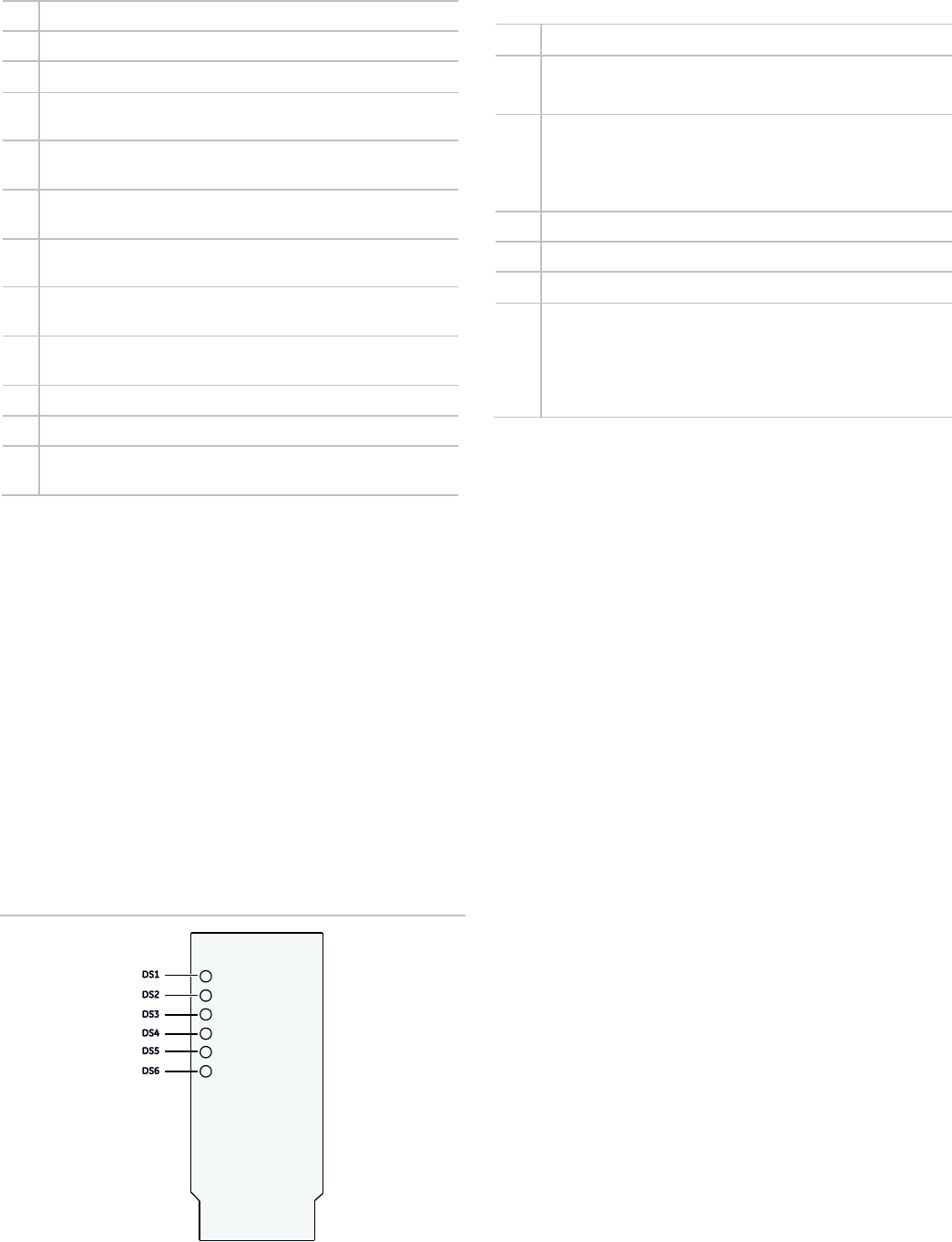
Figure 1: LED locations
Table 2: LED descriptions
LED
Description
DS1
Bus action
• Flashes when connected to NetworX bus
DS2
USB
• Off = no USB
• Flashes = in progress
• Steady = USB attached
DS3
Receiving USB
DS4
Sending USB
DS5
Waiting for bus response
DS6
Programming/error
• Flashes slow ly (once per second) = programming in
progress
• Flashes rapidly (three times per second) = error
• Steady = programming successful
Reviewing segments and tasks for location 0
The only location you will use on the NX-588E is Location 0.
The seven segments have the following functions:
Segment 1
Sets the task to perform (read or write) and displays the result
of the task requested (see Table 1 on page 2).
Segment 2
This stores the file number for the requested read or write
command, a valid value between 1 and 4. This segment is
always set to 0 after any command, so you don’t accidentally
overwrite a file.
Segments 3 through 6
Indicates the panel type stored in files 1 through 4 respectively.
The results include the following:
• 0 to 3 applies to the standard NetworX panels (NX-4, NX-
6, NX-8)
• 4 applies to the NX-8E panel
• 10 applies to the NX-4V2 panel
• 11 applies to the NX-6V2 panel
• 12 applies to the NX-8V2 panel
Segment 7.
Not used.
Upgrading the NX-4V2, NX-6V2, NX-8V2
When upgrading a control panel, all auxiliary outputs will
deenergize. Do not be concerned with any sound that comes
4 NX-588E USB Flash Programmer Installation Instructions
from either the auxiliary outputs or relays, just disconnect the
auxiliary outputs before you upgrade.
Writing from the PC to the NX-588E
To write firmware from the PC to the NX-588, do the following:
1. Connect the NX-588E to the USB port.
2. Double-click the shortcut to NXProg.exe. The NX-588E
must be connected before this step or the application
needs to be closed and restarted to work properly. The
application automatically selects the COM port where the
NX-588E is installed.
3. Select Open file and find the desired file.
4. Select Transfer file. The DS6 LED on the NX-588E flashes
slowly (once per second). The NXProg application
indicates, in a prompt above the status bar, whether the
firmware was successfully written or not. Refer to Figure 1
on page 3 for LED descriptions, or “Troubleshooting” on
page 5 for error descriptions.
5. When you finish, remove the NX-588E from the computer.
Writing firmware from your computer to the panel
To write firmware to a control panel or module from the
NX-588E with a computer connected, is first write the file to the
NX-588E, then write it to the control panel or module.
1. Connect the NX-588E to the USB port.
2. Double-click the shortcut to NXProg.exe. The NX-588E
must be connected before this step or the application must
be closed and restarted to work properly. The application
automatically selects the COM port where the NX-588E is
installed.
3. Select Open file and select the file you require.
4. Select Transfer file. The DS6 LED on the NX-588E flashes
slowly (once per second).
The NXProg application indicates, in a prompt above the
progress bar, whether the firmware was successfully written or
not. Refer to Figure 1 on page 3 for LED descriptions or
“Troubleshooting” on page 5 for error descriptions.
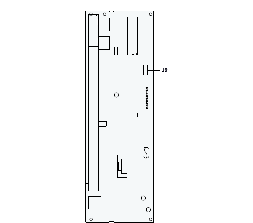
To flash the file from your computer, do the following:
1. Attach the 5-pin cable of the NX-588E to the control
panel’s or module’s J9 program connector (Figure 2
below).
Figure 2: J9 programming connector
Note: For boards with a nonkeyed program connector, PIN 1 is
located by the designator (J9) on the circuit board.
2. If the panel/module is not already powered up, connect to
AC (not battery only) before starting the flash process.
3. Select Upgrade to upgrade the firmware. The DS6 LED
flashes as the firmware is written. The DS6 LED becomes
solid when the upgrade is complete, and flashes three
times per second if the upgrade fails. The NXProg
application indicates, in a prompt above the progress bar,
whether the firmware was successfully written or not. (See
“Troubleshooting” on page 5 for a list of error
descriptions.)
2. When you finish, remove the NX-588E from the computer
and the control panel.
Writing firmware from the NX-588E to the panel
To write firmware to a control panel or module from the
NX-588E directly to the panel, do the following:
1. Connect the NX-588E to the USB port.
2. Double-click the shortcut to NXProg.exe. The NX-588E
must be connected before this step or the application
needs to be closed and restarted to work properly. The
application automatically selects the COM port where the
NX-588E is installed.
3. Select Open file and find the file desired.
4. Select Transfer file.
The DS6 LED flashes slowly (once per second). The NXProg
application indicates, in a prompt above the progress bar,
whether the firmware was successfully written or not. (See

NX-588E USB Flash Programmer Installation Instructions 5
Figure 1 on page 3 for LED descriptions, or “Troubleshooting”
below for error descriptions.)
To flash the file from your computer, do the following:
1. Disconnect the NX-588E from the computer.
2. Attach the 5-pin cable of the NX-588E to the control panel
or module’s J9 program connector (Figure 2 on page 4).
3. If the panel/module is not already powered up, connect to
AC (not battery only). The DS6 LED flashes slowly (once
per second). When the upgrade is complete, the DS6 LED
becomes solid. If the upgrade fails, the DS6 flashes
quickly.
4. When you finish, remove the NX-588E from both the
computer and the control panel.
Troubleshooting
Table 3: Error descriptions
Failure text
Description
Connect (OP)
Could not open USB comport. Make sure the NX-
588E is connected and drivers are installed properly
before starting NXProg.
Connect (IP)
COM port associated w ith PC’s USB is invalid. Make
sure the NX-588E is connected and drivers are
installed properly before starting NXProg.
Version
Version of NX-588E is not compatible w ith version of
NXProg. Upgrade NXProg and/or NX-588E
firmw are.
Connect (SP)
Could not initiate programming w ith NX-588E.
Transfer (PM)
Error in transfer of program memory.
Transfer (ID)
Error in transfer of ID memory.
transfer (EE)
Error in transfer of EEPROM memory.
Transfer (CL)
Error in transfer of configuration memory.
Verify (PM)
Error in verifying transfer of program memory.
Verify (ID)
Error in verifying transfer of ID memory.
Verify (EE)
Error in verifying transfer of EEPROM memory.
Verify (CL)
Error in verifying transfer of configuration memory.
Disconnecting
Error disconnecting from NX-588E.
Connect
(GMV)
NX-588E memory map version not compatible.
Upgrade NXProg and/or NX-588E firmw are.
Connect (GID)
Not connected to an NX-588E.
Connect
(GFV)
NX-588E firmw are version not compatible. Upgrade
NXProg and/or NX-588E firmw are.
Flash (SF)
Could not start the update firmw are process.
canceled
Updating canceled.
Flash (01)
Flashed an unknow n chip. Connected to correct
product?
Flash (02)
Trying to flash a different chip. Connected to correct
product?
Flash (03)
Flash program memory invalid.
Flash (04)
Flash ID memory invalid.
Flash (05)
Flash configuration memory invalid.
Flash (06)
Verifying flash failed; bad checksum.
Flash (07)
NX-588E does not have a complete file loaded.
Reload file.
Flash (08)
Trying to update firmw are of unknown product.
Flash (09)
Not connected or incorrectly connected.
Flash (10)
Internal EEPROM failed.
Flash (11)
Initial configuration failed.
Flash (12)
Processor failed to enter programming.
Flash (13)
Could not store needed code data.
Note: The 5-pin connector is not keyed, so if the NX-588E
doesn’t power up immediately, unplug the connector and
connect it the other way.
Contact information
For contact information, see www.utcfireandsecurity.com or
www.interlogix.com.
For technical support, toll-free: 888.437.3287 in the US
including Alaska, Hawaii, Puerto Rico, and Canada. Outside
the tool-free area, contact your dealer.
© 2012 UTC Fire & Security Americas Corporation, Inc.
Interlogix is part of UTC Climate Controls & Security, a unit of
United Technologies Corporation.
All rights reserved.
