InterLogix 466 2451 B Simon Xti Install Manual Installation User
2016-04-15
User Manual: InterLogix 466-2451-B-Simon-Xti-Install-Manual
Open the PDF directly: View PDF ![]() .
.
Page Count: 78

Simon XTi Installation Manual
P/N 466-2451 • REV B • 18DEC13

Copyright
© 2012-2013 United Technologies Corporation. Interlogix is part of UTC Building and
Industrial Systems, a unit of United Technologies Corporation. All rights reserved.
Trademarks and
patents
The Simon XTi name and logo are trademarks of UTC Fire & Security.
Other trade names used in this document may be trademarks or registered
trademarks of the manufacturers or vendors of the respective products.
Manufacturer
UTC Fire & Security Americas Corporation, Inc.
1275 Red Fox Rd., Arden Hills, MN 55112-6943, USA
FCC compliance
This equipment has been tested and found to comply with the limits for a Class B
digital device, pursuant to Part 15 of the FCC rules. These limits are designed to
provide reasonable protection against harmful interference when the equipment is
operated in a residential environment. This equipment generates, uses, and can
radiate radio frequency energy and, if not installed and used in accordance with the
instruction manual, may cause harmful interference to radio communications.
FCC Part 15 registration number: B4Z-910C-SIMON
IC: 1175C-910CSIMO
Part 68. This equipment complies with Part 68 of the FCC rules and the requirements
adopted by the ACTA.
FCC registration number: US: B4ZAK02B55910
Canada: 1175C-910SIXT
Ringer Equivalence 0.2B
Load Number 0.2
Contact information
www.utcfireandsecurity.com or www.interlogix.com
Customer support
www.interlogix.com/customer-support
Simon XTi Installation Manual i
Content
Product overview ......................................................................... 1
System components ....................................................................... 2
Standard panel ............................................................................... 3
Planning the installation .............................................................. 4
Planning sensor types and locations .............................................. 4
Cross-zoning .................................................................................. 8
System configuration ...................................................................... 9
Installation .................................................................................. 14
Mounting ...................................................................................... 14
Connecting hardwired devices ..................................................... 15
Wiring a phone line to the panel ................................................... 18
Wiring the power transformer ....................................................... 20
Resetting memory to factory defaults ........................................... 21
Applying AC power ....................................................................... 22
Designer template ........................................................................ 23
System configuration................................................................. 26
Status & Settings menu navigation ............................................... 28
Programming .............................................................................. 36
Access codes ............................................................................... 37
Security ........................................................................................ 38
Phone numbers ............................................................................ 40
Phone options .............................................................................. 41
Sensors ........................................................................................ 43
Reporting ..................................................................................... 47
Timers .......................................................................................... 50
Touchpad options......................................................................... 53
System options ............................................................................ 53
Siren options ................................................................................ 55
Audio verification options ............................................................. 56
System tests ................................................................................ 58
Testing ........................................................................................ 59
Sensor test ................................................................................... 60
System download ......................................................................... 64
Offsite phone operation ................................................................ 64
Two-way voice operation.............................................................. 65
ii Simon XTi Installation Manual
Voice event notification ................................................................. 65
Cleaning the touch screen ............................................................ 66
Disposal ........................................................................................ 66
Troubleshooting ......................................................................... 67
Specifications ............................................................................. 68
Sensor names ............................................................................. 69
Simon XTi system quick reference ............................................ 73
Simon XTi Installation Manual 1
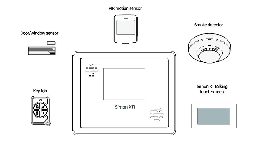
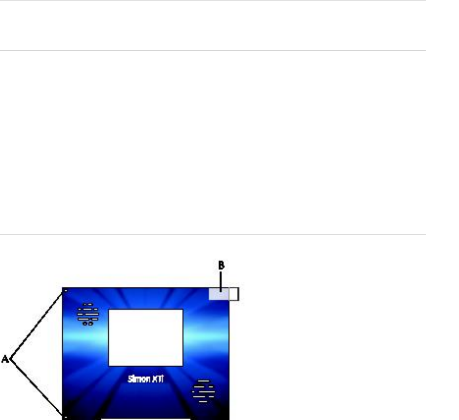
Product overview
This security system can be used as a fire warning system, an intrusion alarm
system, an emergency notification system, or any combination of the three. The
system has three types of components:
• Self-contained control panel
• Devices that report to the panel
• Devices that respond to commands from the panel
Figure 1: Simon XTi system
The self-contained panel provides the main processing unit for all system
functions. It receives and responds to signals from wireless sensors and wireless
touchpads throughout the premises. For monitored systems, the panel can be
connected to the premises phone line for central monitoring station reporting.
You can program the panel onsite from the keypad or remotely using Enterprise
Downloader software. See “Programming” on page 36 for complete onsite
programming instructions.

2 Simon XTi Installation Manual
System components
The system can monitor up to 40 sensors and may use any of the devices listed
in Table 1 below.
Table 1: Supported devices
Device
Description
Max Life Door/window sensor
(60-362N-10-319.5)
For intrusion protection, install door/window sensors on all
ground-floor doors and windows. At a minimum, install them in the
following locations:
• All easily accessible exterior doors and windows.
• Interior doors leading into the garage.
• Doors to areas containing valuables.
Indoor motion sensor
(60-639 & 60-807-95)
Indoor motion sensors are ideal whenever it is not practical to
install door/window sensors on every opening. Identify areas
where an intruder is likely to walk through. Large areas in an open
floor plan, downstairs family rooms, and hallways are typical
locations for indoor motion sensors. For installations with pets,
use the SAW Pet Immune PIR (60-807-95).
Smoke sensor
(TX-6010-01-1)
Smoke sensors provide fire protection by causing an alarm to
sound throughout the house. You can add smoke sensors near
sleeping areas and on every floor of the house. Avoid areas that
could have some smoke or exhaust such as attics, kitchens,
above fireplaces, dusty locations, garages, and areas with
temperature extremes. In these areas, you may want to install
rate-of-rise sensors to detect extreme temperature changes. See
the instructions packaged with the smoke sensor for complete
placement information.
Glassbreak sensor (60-873-
95)
Glassbreak sensors respond to shock waves of breaking glass.
These sensors are designed to mount in the corner of windows or
doors, either on the frame or on the glass itself. See the
instructions packaged with the glassbreak sensor for complete
placement information.
Carbon monoxide (CO) alarm
(TX-6310-01-1/600-6520-95)
The learn mode CO alarm alerts you to hazardous levels of
carbon monoxide gas. If dangerous concentrations of gas are
present, the red indicator light comes on, the internal siren goes
off, and an alarm is transmitted to the panel. The panel sounds its
own alarm and reports to the central station.
4-Button Key fob
(600-1064-95R)
The key fob (keychain touchpad) lets you turn the system on and
off from right outside the home or activate a panic alarm if there is
an emergency. If you have the appropriate light control modules,
you can use key fobs to turn all system controlled lights on and
off.
Simon XT Talking Touchpad
(60-924-3-XT)
The wall-mounted, two-way, talking touchpad combines a
conventional learn mode touchpad with an RF receiver, speech
chip, and voice amplification circuit.

Simon XTi Installation Manual 3
Device
Description
Simon XT talking touch
screen
(60-924-RF-TS, 60-924-3-
XT-2WTTS and 60-924-RF-
TS-N)
The two-way talking touch screen is a wireless device that
provides a graphical user interface that allows you to: arm the
system (doors, windows, and motion sensors), disarm the system,
activate a panic alarm to call the central monitoring station in an
emergency, check system status, and turn system controlled
lights on or off, all while providing voice feedback. The touch
screen also provides trouble beeps, entry/exit beeps, and alarm
sounds (Fire, Panic, Police).
Caution: Do not use outdoor motion sensors for intrusion protection.
Standard panel
Table 2 below describes the basic panel (out-of-box) hardware capabilities for
the Simon XTi 600-1054-95R-12 and 600-1054-95R-12-CN.
Table 2: Panel hardware capabilities
Hardware
Capability
Power
Input for an AC step-down, plug-in style transformer.
One siren output, up to two
zone inputs
Terminals for connecting hardware sirens or normally closed
(NC) loop switch circuits.
Phone line connection
Allows the panel to communicate with the central monitoring
station and/or remote phone.

4 Simon XTi Installation Manual
Planning the installation
This section describes system capabilities to help you get familiar with your
system. The planning sheets contain tables that let you record the hardware and
programming configuration of your system. Complete all of the information ahead
of time to help prepare for system installation. See “Sensor names” on page 69
for sensor name segments listed alphabetically and by index number.
Locate the panel where alarm sounds can be heard and where the panel will be
easily accessible for operation. Do not install the panel near a window or door
where it can be reached easily by an intruder.
Planning sensor types and locations
The first step to an easy and successful installation is to decide what areas or
items to protect, which lights to operate, and the best location for the panel,
touchpad, sensors, and sirens. Metal objects, mirrors, and metallic wallpaper can
block signals sent by the wireless sensors. Make sure there are no metal objects
in the way when installing the system.
Use Table 3 below and Table 4 on page 5 to determine the appropriate sensor
type for the sensors you will be adding, and Table 5 on page 7 to document the
planned sensor information. You will need to understand the application for each
sensor.
Table 3: Recommended sensor groups
Device
Recommended sensor group
Indoor motion sensor
15, 17 (intrusion) 18, 20, 25 (chime), 28, or 32 a
Outdoor motion sensor
25 (chime only group) b
Entry/exit door
10
Interior door
14
Window sensor
13
Smoke sensor
26 c
Glassbreak sensor
13
Key fob
01 b, 03, 06, 07
Simon XT talking touchpad
01 b, 04, 05, 06, 07
Simon XT talking touch screen
00, 01 b & d, 04, 05, 06, 07
CO alarm
34 b
a. Not certified as a primary protection circuit for UL-listed systems and is for supplementary
use only.
b. Has not been investigated by UL.
c. Required for UL-listed residential fire alarm applications.
d. Additional devices employing UTCFS 80 Bit Enhanced Protocol have not been
investigated for use in a UL Listed installation.

Simon XTi Installation Manual 5
Table 4: Sensor group characteristics
Type
Name/application
Siren type
Delay
Restoral
Supervise
d
Active in
arming
levels
00
Fixed panic: 24-hour audible fixed emergency button.
Intrusion
I
N
Y
1234
01
Portable panic: 24-hour audible portable emergency
button.
Intrusion
I
N
N
1234
02
Fixed panic: 24-hour silent fixed emergency button.
Status light will not blink.
Silent
I
N
N
1234
03
Portable panic: 24-hour silent portable emergency
buttons. Status light will not blink.
Silent
I
N
N
1234
04
Fixed auxiliary: 24-hour auxiliary sensor.
Emergency
I
N
Y
1234
05
Fixed auxiliary: 24-hour emergency button. Siren
shut off confirms CS report.
Emergency
I
N
Y
1234
06
Portable auxiliary: 24-hour portable auxiliary alert
button.
Emergency
I
N
N
1234
07
Portable auxiliary: 24-hour portable auxiliary button.
Siren shut off confirms CS report.
Emergency
I
N
N
1234
08
Special intrusion: Such as gun cabinets and wall
safes.
Intrusion
I
Y
Y
1234
09
Special intrusion: Such as gun cabinets and wall
safes.
Intrusion
S
Y
Y
1234
10
Entry/exit delay: A delay that requires a standard
delay time. Chime.
Intrusion
S
Y
Y
24
13
Instant perimeter: Exterior doors and windows.
Chime.
Intrusion
I
Y
Y
24
14
Instant interior: Interior door.
Intrusion
F
Y
Y
234
15
Instant interior: Interior PIR motion sensor.
Intrusion
F
N
Y
234
16
Instant interior: Interior door.
Intrusion
F
Y
Y
34
17
Instant interior: PIR motion sensor and sound
sensor.
Intrusion
F
N
Y
34
18
Instant interior: Cross-zone PIR motion sensor.
Intrusion
F
N
Y
34
19
Delayed interior: Interior doors that initiate a delay
before going into alarm.
Intrusion
S
Y
Y
34
20
Delayed interior: PIR motion sensor that initiates a
delay before going into alarm.
Intrusion
S
N
Y
34
21
Local instant interior: 24-hour local alarm zone
protecting anything that opens and closes. No report.
Intrusion
I
Y
Y
1234
22
Local delayed interior: Same as group 21, plus
activation initiates a delay before going into alarm.
No report.
Intrusion
S
Y
Y
1234

6 Simon XTi Installation Manual
Type
Name/application
Siren type
Delay
Restoral
Supervise
d
Active in
arming
levels
23
Local instant auxiliary: 24-hour local alarm zone
protecting anything that opens and closes. No report.
Emergency
I
Y
Y
1234
24
Local instant auxiliary: 24-hour local alarm zone
protecting anything that opens and closes. Sirens
shut off at restoral. No report.
Emergency
I
Y
Y
1234
25
Local special chime: Notify the user when a door is
opened.
Three
beeps
I
N
Y
1234
26
Fire: 24-hour fire, rate-of-rise heat, and smoke
sensor.
Fire
I
Y
Y
1234
27
Lamp control or other customer feature. No report.
Silent
I
Y
Y
1234
28
PIR motion sensor, sound sensor, or pressure mat.
RF thermostat. No report.
Silent
I
N
Y
1234
29
Auxiliary: Freeze sensor.
Trouble
beeps
I
Y
Y
1234
32
PIR motion sensor or sound sensor. No report.
Silent
I
N
N
1234
34
Carbon monoxide alarm.
Emergency
I
Y
Y
1234
35
Entry/exit delay interior PIR motion.
Intrusion
S
N
Y
234
36
Special intrusion: Such as gun cabinets and wall
safes. Reports as tamper if tripped.
Intrusion
I
Y
Y
1234
38
Auxiliary: Water sensor.
Trouble
beeps
I
Y
Y
1234
39
Local instant interior: 24-hour local alarm zone
protecting anything that opens and closes. No report.
Intrusion
I
Y
N
1234
40
Local special chime.
Three
beeps
I
Y
Y
1234
43
Property/asset management: Notify the user that a
protected asset has moved.
Note: We recommend you use this sensor group in
combination with a Simon XT Talking Touch Screen.
One beep
I
N
Y
1234

Simon XTi Installation Manual 7
Table 5: Sensor assignments/locations
Sensor
#
Device
Sensor
group
Sensor name/location
Notes
01
02
03
04
05
06
07
08
09
10
11
12
13
14
15
16
17
18
19
20
21
22
23
24
25
26
27
28
29
30
31
32
33
8 Simon XTi Installation Manual
Sensor
#
Device
Sensor
group
Sensor name/location
Notes
34
35
36
37
38
39
40
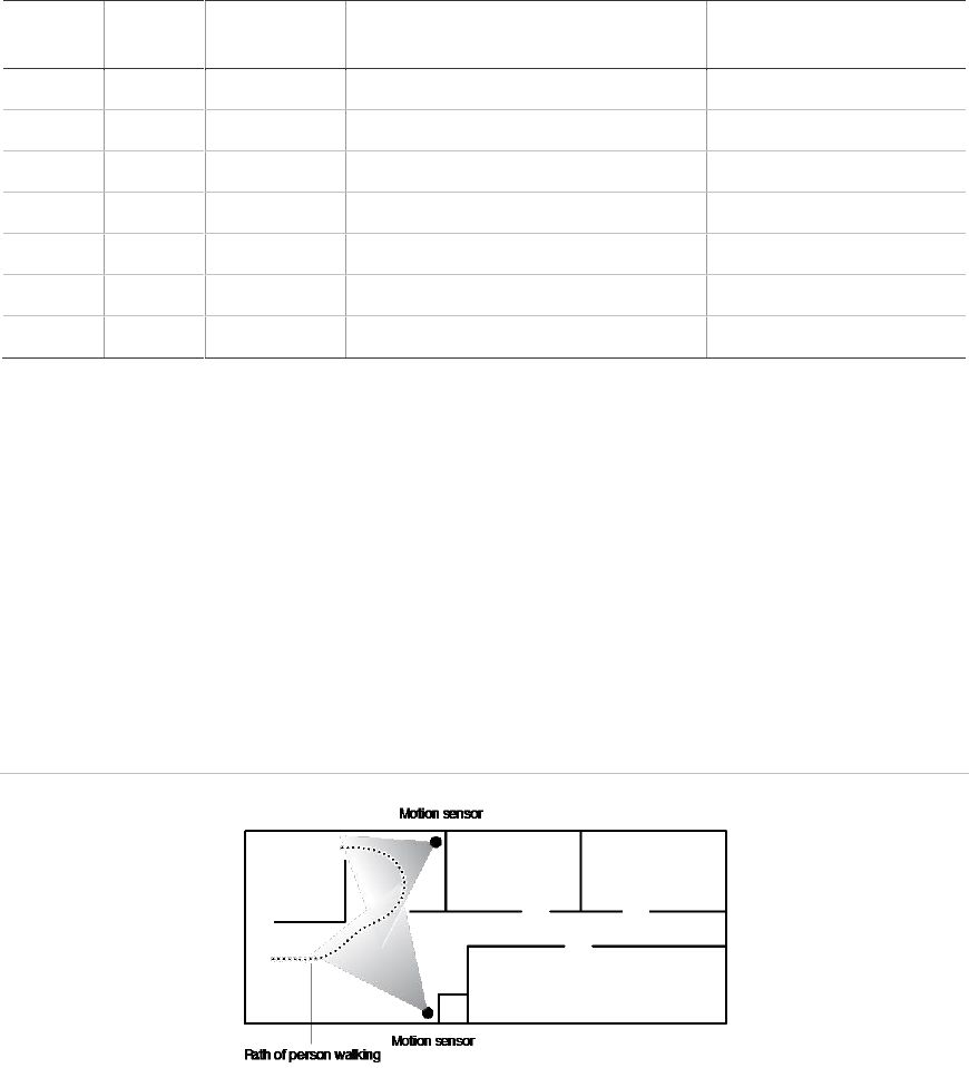
Cross-zoning
Cross zoning (two-trip) refers to two different group 18 sensors that must be
tripped within two minutes of each other to report an alarm to the central station.
Figure 2 below shows the path of a person walking from the kitchen to the living
room. When the person is detected walking through the kitchen, the motion
sensor in the kitchen is tripped, sounding a local alarm. If motion is detected by
the living room motion sensor within two minutes, an alarm report will be sent to
the central station.
Figure 2: Cross-zone diagram
Note: We do not recommend cross zoning for exit/entry zones. Each zone can
individually protect the intended area.

Simon XTi Installation Manual 9
System configuration
Table 6 below is a worksheet for you to record the desired values for each
programming option. For each option, the default value, effect of deletion
(pressing Disarm while editing), range, and programming privilege are listed.
Each option is described in more detail in “Programming” on page 36.
In the table, the Access code column indicates what type of access code is
allowed to make changes: D = dealer code, I = installer code, M = master code.
Table 6: Programming menu options
Function
Default
Delete
Range
Access
code
Installer
settings
Access codes menu
Dealer code
654321,
54321, 4321,
or 321
None
3 to 6 digits
D
Installer code
654321,
54321, 4321,
or 321
None
3 to 6 digits
D, I
Master code
123456,
12345, 1234,
or 123
None
3 to 6 digits
D, I, M
User code 1
None
None
3 to 6 digits
D, I, M
User code 2
None
None
3 to 6 digits
D, I, M
User code 3
None
None
3 to 6 digits
D, I, M
User code 4
None
None
3 to 6 digits
D, I, M
User code 5
None
None
3 to 6 digits
D, I, M
User code 6
None
None
3 to 6 digits
D, I, M
User code 7
None
None
3 to 6 digits
D, I, M
User code 8
None
None
3 to 6 digits
D, I, M
Duress code
None
None
3 to 6 digits
D, I, M
Code length
4
3 to 6 digits
D
Security menu
Account number
00000
00000
0 to FFFFFFFFFF
D, I
Downloader code
12345
12345
00000 to 99999
D
Phone lock
Off
On/Off
D
Auto arm
On
On/Off
D, I
Exit extension
On
On/Off
D, I
Secure arming
Off
On/Off
D, I

10 Simon XTi Installation Manual
Function
Default
Delete
Range
Access
code
Installer
settings
No arm on panel low
battery
Off
On/Off
D, I
Quick exit
Off
On/Off
D, I
Downloader enable
On
On/Off
D, I, M
Phone # menu
Phone #1
None
None
26 digits
D
Phone #2
None
None
26 digits
D
Phone #3
None
None
26 digits
D, I
Phone #4
None
None
26 digits
D, I, M
Downloader #
None
None
26 digits
D, I
Phone options menu
Manual phone test
On
On/Off
D, I
Fail to communicate
On
On/Off
D, I
DTMF dialing
On
(touchtone)
On/Off
D, I
300 bps baud rate
On (300 bps)
On/Off
D, I
Ring/hang/ring
RHR or 10
Ring
• RHR or 10 Rings
• RHR(2) or 10
Rings
• RHR(3) or 10
Rings
• 10 Rings
• RHR
• RHR(2)
• RHR(3)
• Off
D, I
Dial delay
30 seconds
15 seconds
15 to 45 seconds
D, I
Call waiting code
None
None
26 digits
D, I
Sensors menu
Learn sensors
D, I
Delete sensors
D, I
Edit sensors
D, I
Reporting menu
Report options
Opening reports
Off
On/Off
D, I
Closing reports
Off
On/Off
D, I
Forced armed
Off
On/Off
D, I

Simon XTi Installation Manual 11
Function
Default
Delete
Range
Access
code
Installer
settings
AC power failure
report
Off
Off
5 to 254 minutes/Off
D, I
Panel Low battery
report
On
On/Off
D, I
Sensor alarm restoral
report
Off
• Sensor Close
• Siren Timeout
• System
Disarmed
• Off
D, I
24-hour sensor
tamper report
Off
On/Off
D, I
Supervisory/ tamper
report
Off
On/Off
D, I
No usage report
Off
Off
2 to 254 days/Off
D, I
Swinger shutdown
On
On/Off
D, I
Programming report
Off
On/Off
D, I
Fire alarm verification
Off
On/Off
D, I
Communication modes
Phone 1 report mode
Off
All SIA, All CID,
Alarms SIA, Alarms
CID, Nonalarm SIA,
Nonalarm CID,
Backup SIA, Backup
CID, Voice dialer, or
Off
D
Phone 2 report mode
Off
D
Phone 3 report mode
Off
D, I
Phone 4 report mode
Off
D, I
Timers menu
Entry delay
30 seconds
30
30 to 240 seconds
D, I
Exit delay
60 seconds
45 seconds
45 to 254 seconds
D, I
No activity timeout
Off
Off
2 to 24 hours/Off
D, I
Auto phone test
Off
Off
1 to 254 days/Off
D, I
Supervisory time
12:00 AM
None
12:00 AM (midnight)
to 11:59 PM, None
D, I
Alarm cancel window
6 minutes
Off
6 to 255 minutes,
Off
D, I
RF timeout
12 hours
12 hours
2 to 36 hours
D, I
Fail to open time
Off
Off
12:00 midnight to
11:59 PM, Off
D, I
Fail to close time
Off
Off
12:00 midnight to
11:59 PM, Off
D, I
Siren timeout
5 minutes
Off
2 to 254 minutes,
Off
D, I

12 Simon XTi Installation Manual
Function
Default
Delete
Range
Access
code
Installer
settings
Unvacated premises
On
On/Off
D, I
Smoke supervision
Off
On/Off
D, I
Touchpad options menu
Key fob no delay
Off
On/Off
D, I
Panic alarms
On
On/Off
D, I
Remote touchpad
arming
Off
On/Off
D, I
System options menu
RF jam detect
Off
Off
On/Off
D, I
Demo mode
Off
Off
On/Off
D, I
HW1 function
Interior siren
• Interior Siren-
Interior siren
output
• Armed-Output
activated when
armed
• Disarmed-
Output activated
when disarmed
• FTC-FTC output
(FTC must be
on)
• Alarm-Output
activated for
alarm
• Exterior Siren–
Exterior siren
output
• Off-No output
D
24-hour clock
Off
On/Off
D, I
Siren options menu
Panel piezo beeps
On
On/Off
D, I, M
Panel voice
On
On/Off
D, I, M
Panel piezo alarms
On
On/Off
D, I, M
Trouble beeps
On
On/Off
D, I
Voice chime
Off
• Voice chime
(sensor name)
• Chime bell
• Soft chime bell
• Off-No voice
chime
D, I,
Hardwired siren
supervision
Off
On/Off
D, I

Simon XTi Installation Manual 13
Function
Default
Delete
Range
Access
code
Installer
settings
Panel silent police
panic
Off
On (silent), Off
(audible)
D, I
Alarm report
verification
Off
On/Off
D, I
Audio verification menu
Audio mode
Off
• Instant mode
• Callback mode
• Off
D, I
Fire shutdown
Off
On/Off
D, I
Fire enabled AVM
On
On/Off
D, I
Panic talk
Off
On/Off
D, I
Vox receiver gain
6
6
1 to 32
D, I
Vox microphone gain
24
24
1 to 64
D, I
Vox microphone gain
range
64
64
1 to 64
D, I
Manual microphone
gain
64
64
1 to 64
D, I
System test menu
Sensor test
D, I, M
Communication test
D, I, M
System download
D, I, M
14 Simon XTi Installation Manual
Installation
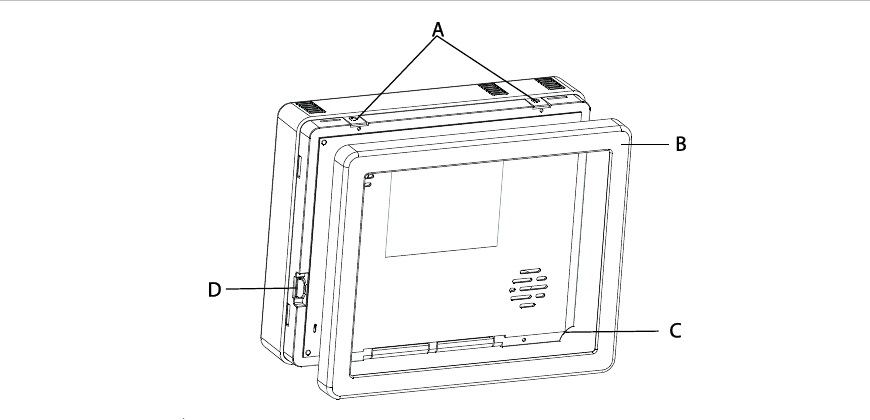
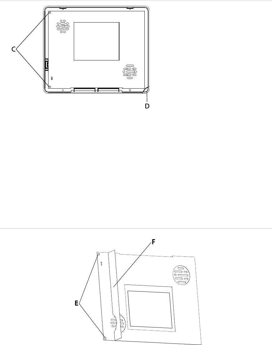
Mounting
Figure 3: XTi chassis and trim ring
To mount the panel on a wall:
1. Lay the panel flat on a table.
2. Remove trim ring (B in Figure 3 above) from panel by lifting at notch (C in
Figure 3 above).
3. Separate the panel chassis from the mounting plate by lifting up on the tabs
(A in Figure 3 above) and swinging the chassis open.
4. Choose a panel location.
5. Run all necessary power, phone, siren, and hardwired contact wires to the
desired panel location.
Note: When choosing the AC outlet location for the AC power transformer,
make sure the outlet is not controlled by a switch or that it is not part of a
ground fault circuit interrupt (GFCI).
6. Hold the mounting plate against the wall and mark the mounting hole
locations (Figure 4 on page 15) with a pencil.
Note: Mark both mounting holes in the middle of the mounting slot. This will
allow better adjustment of the panel before securing it to the wall.
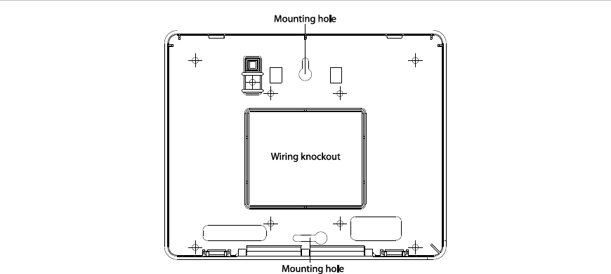
Simon XTi Installation Manual 15
Figure 4: Mounting holes
7. Secure the mounting screws (provided) to the locations on the wall marked in
step 6. Do not tighten the screws. Leave enough clearance to mount the
mounting plate.
Note: Use wall anchors if no studs are present.
8. Mount the mounting plate to the wall. Insert the top mounting hole first, then
the bottom hole. Adjust the fit to make sure the mounting plate is level. Hold
the mounting plate in place and tighten the screws.
9. Hang the panel chassis on the mounting plate at the plastic hinges, swing the
chassis up to the mounting plate and engage at the tabs (A in Figure 3 on
page 14).
10. Insert the two supplied screws through the tabs (A in Figure 3 on page 14) to
secure the mounting plate to the panel chassis. Tighten the screws.
11. Reattach the trim ring.
Connecting hardwired devices
The panel has five screw terminals, two battery terminals, and two telephone
connections. The screw terminals connect the AC power, sirens, and/or
hardwired detectors.

16 Simon XTi Installation Manual
Figure 5: Wiring terminals
Program sensors and devices before you install them. Follow the instructions in
“Sensors” on page 43 to add the sensors to panel memory.
The HW1 I/O terminal is dual purpose and can be used for either siren or
hardwired contact connections. The HW2 in terminal is an input only.
Interior sirens
From the factory, the HW1 I/O input is set up for interior siren operation (status
and alarm sounds). The HW1&2 DC out terminal provides the positive (+)
voltage.
Note: The total current available from the HW1&2 DC out terminal is 250 mA at
up to 120ºF (49ºC). A 24-hour battery standby will be met with a maximum load
of 250 mA.
With hardwired siren supervision turned on, sirens connected to HW1 I/O are
supervised and require a 4.7-kohm resistor in the circuit. If this terminal is not
used, turn hardwired siren supervision off.
Hardwired interior siren
Interior sirens must always be wired with a resistor in the circuit. For circuit
supervision, which allows the panel to detect if the siren wire is cut (open), the
hardwired siren supervision option must be turned on.
Note: Do not install the resistor at the panel terminals. This does not provide
supervision of the wire.
Connect the hardwired interior siren (13-374) to the panel using a 4.7 kohm
resistor (included with the siren) as shown in Figure 6 on page 17. The resistor
must be connected across the siren wires as close to the siren as possible.
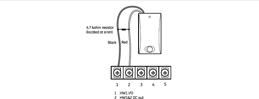
Simon XTi Installation Manual 17
Figure 6: Hardwired interior siren with supervision
Exterior sirens
For an exterior siren, reprogram HW1 to Exterior Siren on Option 6. See Wiring
diagram.
Hardwired contacts
To set up HW1 I/O and/or HW2 for hardwired contacts, make the required
connections described below, and then proceed to “Programming” on page 36 to
add (learn) them into panel memory.
You can connect hardwired reed switches (normally closed loop only) to HW1 I/O
(if not being used for a hardwired siren) and/or HW2 in.
Note: Connect only normally closed (NC) reed switches to HW1 I/O and/or HW2
in. Other types of hardwired detectors should not be used.
The total resistance of the wired loop must not exceed 3 ohms. This allows you
to use up to 200 ft. (61 m) of two-conductor, 22-gauge stranded wire.
Connect hardwired reed switches to the panel using a 47-kohm resistor (not a
4.7-kohm resistor) as shown in Figure 7 on page 18. The resistor must be
connected at the last switch in the circuit.
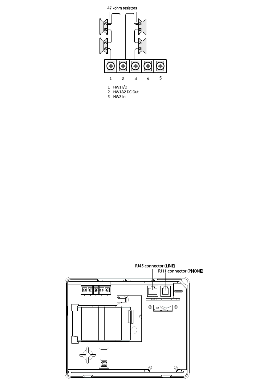
18 Simon XTi Installation Manual
Figure 7: Normally closed hardwired reed switches
Note: Do not install the resistor at the panel terminals. This does not provide
supervision of the wire.
Wiring a phone line to the panel
You can connect a phone line to the panel for systems monitored by a central
monitoring station or systems that notify users by a voice event notification.
DSL (digital subscriber line) allows the use of multiple devices on a single phone
line simultaneously. For DSL environments, connect the panel line-in jack to an
available phone jack on the premises. You may also need an inline filter to
ensure panel reporting is successful.
Note: Avoid connecting the panel to a standard phone (voice) line as other
devices on the line can prevent reports from going through.
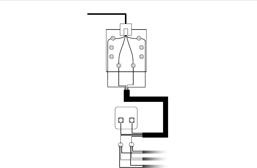
Figure 8: Phone connectors
Simon XTi Installation Manual 19
Full line seizure
Full line seizure allows the panel to take over (seize) the phone line, even if
another device on the line is in use. This method requires that the panel be wired
before all other phones, answering machines, computers, or other devices on the
phone line.
Use the RJ31X (CA-38A) jack when wiring for full line seizure. You can then
quickly and easily disconnect the panel from the phone line in case the panel
disables the phone line due to a malfunction.
To wire full line seizure with an RJ31X:
1. Run a four-conductor cable from the premises Telco block to the RJ31X (see
Figure 9 below).
2. Connect the four-conductor cable wire to the RJ31X.
3. Disconnect the green and red premises phone jack wires from the Telco block
and splice them to the four-conductor cable black and white (or yellow) wires.
Use weatherproof wire connectors for these splices.
4. Connect the four-conductor cable green and red wires to the Telco block TIP
(+) and red to RING (-) posts.
5. Connect the phone cord included with the panel to the RJ31X and the panel
LINE jack.
Figure 9: Full line seizure wiring with RJ31X
Green
Black
Green
Red
White
Red
BRN GRY
(+) (-)
TIP RING
RED
Black White (or Yellow)
Green Red
To RJ45 connector (LINE)
GRN
(or Yellow)
Telco block Four-conductor cable
RJ31X
Phonecord

20 Simon XTi Installation Manual
Full line seizure wiring with one premises phone
If a single phone is all that exists on the premises, full line seizure can be
accomplished without an RJ31X.
1. Disconnect the phone from the premises phone jack and plug it into the panel
PHONE jack. This jack is disconnected automatically whenever the panel
reports.
2. Connect the included phone cord to the panel LINE jack and the premises
phone jack.
Note: If customers add phones or other phone devices to another phone jack, full
line seizure no longer exists. Inform them to contact you if they want to add a
phone or other device so that you can rewire for full line seizure by adding an
RJ31X.
Wiring the power transformer
Connect the power transformer to the two 9 VAC in terminals on the panel.
Note: System can only be powered up using AC power, not battery power. The
red battery icon may appear when system first powers up and will disappear after
some time.
Figure 10: Transformer connections
Do not plug in the transformer at this time. When applying power to the panel
connect the battery first, and then plug in the AC power transformer. This
sequence prevents a battery fault condition.
Note: Maximum battery charge current is 120 mA. It may take up to 36 hours for
a new battery to fully change.
Simon XTi Installation Manual 21
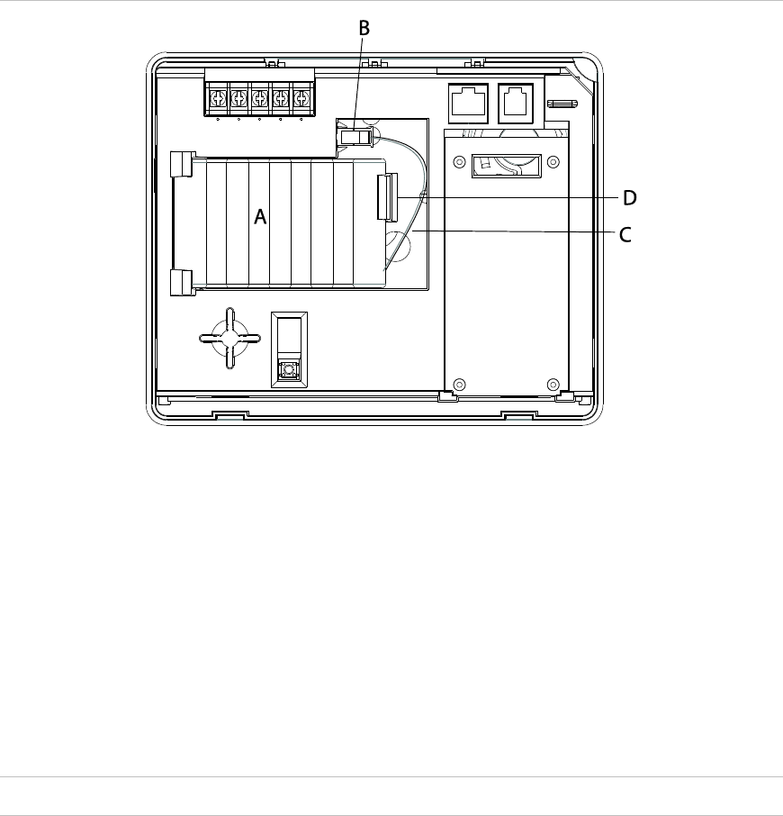
To remove and install the backup battery (6 VDC, 2.1 Ah):
Figure 11: Battery installation
Note: It is recommended that the backup battery be replaced every 3-5 years.
1. Remove AC power from the panel.
2. Disconnect the existing battery (A in Figure 11 above) from the battery
connector (B in Figure 11 above).
3. Remove the existing battery by reaching under the battery, next to the plastic
latch (D in Figure 11 above), with a finger and pulling up.
Note: Do not try to push the plastic latch back to remove the battery.
4. Insert the new battery into the battery compartment and snap into place.
5. Plug the battery connector into the panel.
Caution: Do not connect the battery until you are ready to power up the panel.
Resetting memory to factory defaults
If you need to reset memory to factory defaults, follow the steps below.
To reset the panel to factory defaults:
1. Remove the trim ring.
2. Open the panel cover.
3. Unplug the transformer and disconnect the battery.

22 Simon XTi Installation Manual
4. Press and hold the reset button (D in Figure 3 on page 14) on the left side of
the panel.
5. Plug in the transformer to the panel while holding the reset button and
keeping the panel cover open.
6. Release the button.
7. Plug in the battery and close the panel cover.
8. Replace the trim ring.
Applying AC power
The panel will not power up on battery power only. AC power is required to
power up the panel.
Make sure the outlet is not controlled by a switch or that it is not part of a ground
fault circuit interrupt (GFCI).
Note: For Canadian installations, plug the transformer into the wall outlet.
1. Remove the center screw from the outlet cover plate and hold the cover plate
in place.
WARNING: Use extreme caution when securing the transformer to a metal outlet
cover. You could receive a serious shock if a metal outlet cover drops down onto
the prongs of the plug.
2. Plug the transformer into the lower receptacle of the outlet so that the hole in
the transformer tab lines up with the outlet cover screw hole.
3. Insert the cover plate screw through the transformer tab and the outlet cover
plate. Tighten the screw.
Note: Upon initial installation, the battery may not be fully charged for as long
as 36 hours. A low battery icon will be present and trouble beeps will sound
until the battery is sufficiently charged. After the initial charge, should the
panel lose AC Power and experience a low battery condition, the icon will
appear and trouble beeps will sound unless silenced. You can silence trouble
beeps by:
• Arming or disarming the system.
or
• Pressing the STATUS & SETTINGS icon and pressing LISTEN next to
Panel Status.
This will disable the sounder for 4 hours but the trouble indication will remain
until the battery is recharged.
Simon XTi Installation Manual 23
Designer template
The designer template is the adhesive-backed plastic template that covers the
front of the Simon XTi panel.
Caution: The authorized designer template and its installation are integral parts
to the reliability of the system. Replacement of the authorized designer template
should be done by the security system installer.
Removing the designer template
1. Remove all power (both battery and AC). Use proper ESD protection
practices when replacing the designer template.
2. Remove trim ring from the panel by lifting at notch (D in Figure 13 on page
24).
3. Lift a corner of the template and peel back until it is removed from the front of
the panel.
Installing the designer template
Figure 12: Designer template front
24 Simon XTi Installation Manual
Figure 13: Panel cover
1. Before installing a designer template, ensure that both the display screen and
cover surface are free of any lint. Wipe the surface down with a lint-free cloth.
2. Turn over the template to the back side (paper-backed adhesive side).
3. Position the template so the two alignment holes (A in Figure 12 on page 23)
are vertically located on your left side.
4. Starting at one of the left hand corners, partially peel back the paper backing
about 2 -3 inches to the right (F in Figure 14 below) exposing both of the two
alignment holes (E in Figure 14 below). Crease and flatten the partially
removed paper backing against the back of the template.
Figure 14: Designer template back
5. Turn over the template to the front (cosmetic) side.
6. Position the two alignment holes in the template (A in Figure 12 on page 23)
over the two pins (C in Figure 13 above) located on the cover of the panel.
Simon XTi Installation Manual 25
7. Lightly press down on the left side of the template. Once located, reach under
the template and remove the remainder of the paper backing (F in Figure 14
on page 24).
8. Press down with your thumb on the template from left to right, removing any
air bubbles and ensuring proper adhesion.
9. After the template is adhered to the front of the panel, remove protective film
from front of template by pulling on tab (B in Figure 12 on page 23) in upper
right hand corner.
10. Replace the plastic trim ring on panel.
26 Simon XTi Installation Manual
System configuration
The control panel provides the main processing unit for all system functions. The
programming of system options and features is menu-driven. All installer options
are set in the Programming menu, except for setting the system time and date.
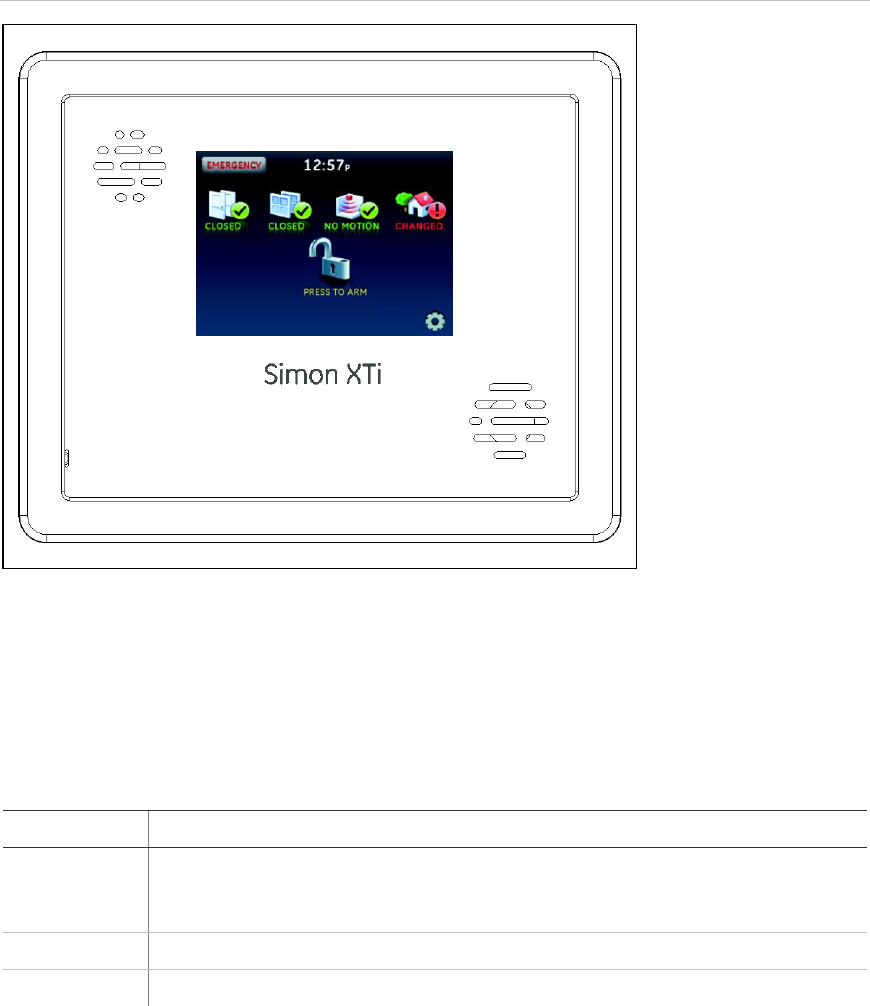
Figure 15 below shows the Simon XTi front panel.
Figure 15: Simon XTi front panel
Note: The touch screen in Figure 15 above is an example. The touch screen and
system being installed may be configured differently.
Table 7 below explains the panel keys and features.
Table 7: Simon XTi panel keys and features
Item
Description
Piezo siren
Provides alarm beeps and status beeps. Fire and intrusion alarm beeps are
always played at high volume, while the volume of status beeps is
programmable.
Touch screen
Provides a graphical user interface for programming and system operation.
Microphone
Used to communicate with the central monitoring station after an alarm.
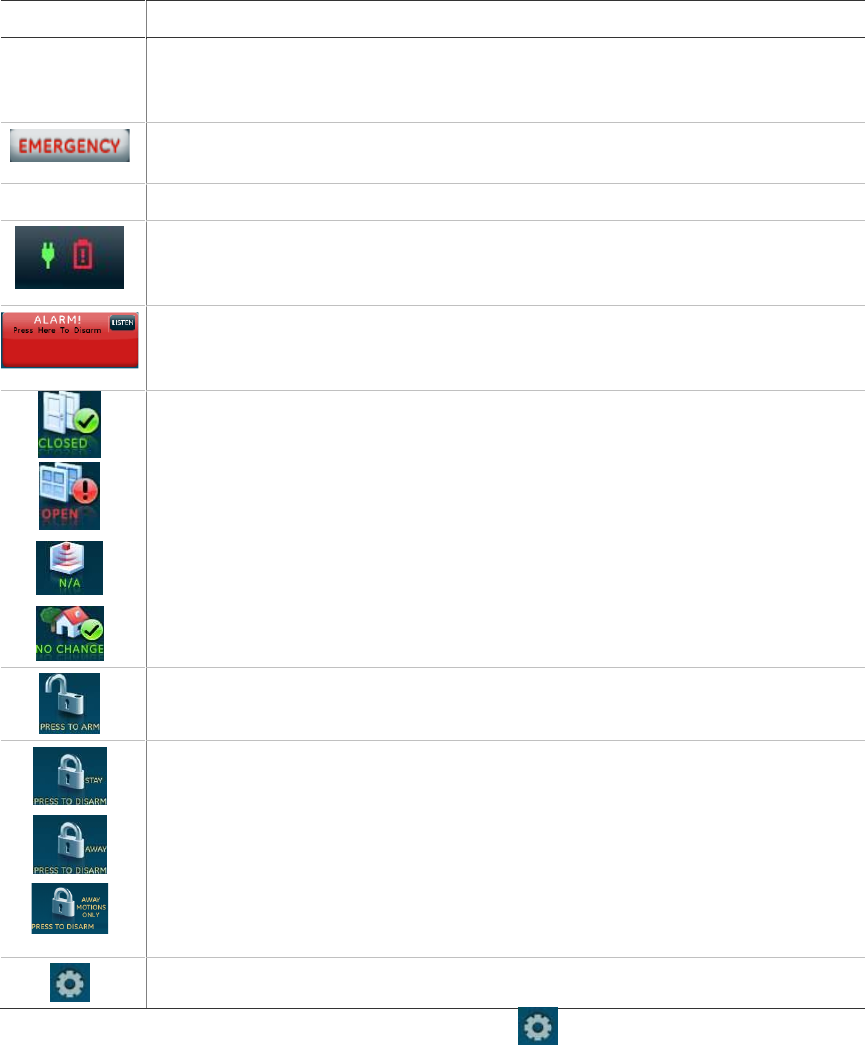
Simon XTi Installation Manual 27
Item
Description
Speaker
Provides voice output and sounds key beeps. The panel speaks arming level
change, system status, and voice chime sensor trips. The panel voice is also
used for voice reporting and remote phone control.
To access the emergency screen and select the appropriate icon (Panic, Police,
or Fire), press EMERGENCY in the top left corner of the touch screen.
Time
The current system time.
Depicts the status of the AC and battery. A green power cord icon represents
AC power to the system. A red battery icon represents low battery power to the
system. A green battery icon represents full battery power to the system.
This will appear on the home screen in the event of an alarm. Messages will
also display on this icon describing what caused the alarm. Press this icon to
cancel the alarm.
These four icons depict the status of the sensors installed in your system.
• A green check indicates sensors are closed or no recent activity detected.
• A red exclamation indicates sensors are open or recent activity has been
detected.
• If the icon shows N/A, your system is not configured to support that type of
sensor.
Pressing these icons will open a new screen to provide more detail.
Press this icon to access the Arming Screen.
One of these icons will display depending on your arming level. Press to turn off
intrusion/burglary protection for your system. Only intrusion/burglary sensors are
disarmed. Environmental sensors, such as smoke and carbon monoxide
detectors, stay active at all times Enter your code in the keypad screen that
appears. If you enter an incorrect code, press the Clear icon and enter the
correct code.
Note: In certain configurations with third party modems, the Motion Only Arming
icon may not be shown.
Press to access the Status & Settings screen.
To enter the Status & Settings screen, press the icon in the bottom right
corner of the touch screen.
Press the Close icon to exit a menu or option edit mode and navigate up one
level. Pressing the Close icon while in the top menu level exits the system menu
level. The panel automatically exits the system menu after a few seconds of
inactivity if no access code has been entered yet. After an access code has been
entered to access a code-protected area of the system menu, the timeout is four
minutes.

28 Simon XTi Installation Manual
Status & Settings menu navigation
Each menu contains a list of options and/or submenus. Press the icons
to navigate up and down the list of options and submenus in that menu. Pressing
Close exits a menu and goes to the next higher level.
Programming options are arranged in a menu structure as outlined in Table 8
below. The top menu contains several features, as well as the Programming
menu. When accessing the Direct Bypass, Programming, or System Tests menu,
the panel prompts you to enter an access code. To continue, enter the dealer,
installer or master code, and then press OK.
A gold icon indicates an option is selected.
A blue icon indicates an option is not selected.
Table 8: Status & Settings menu structure
Event history
Direct bypass
Panel status
Chime
Note: This option may or
may not appear depending
on panel programming.
Special Chime
Note: This option may or
may not appear depending
on panel programming.
Lights
Note: Has not been
investigated by UL.
Door lock
Note: Has not been
investigated by UL
Voice volume
Beep volume
Brightness
Default screen
Calibration
Help
Set date/time
System tests
Sensor test
Comm test

Simon XTi Installation Manual 29
System
download
Programming
Access codes
Dealer code, Installer code, Master code, User
code 1, User code 2, User code 3, User code 4,
User code 5, User code 6, User code 7, User code
8, Duress code, Code length
Security
Account number, Downloader code, Phone lock,
Auto arm, Exit extension, Secure arming, No arm
on panel low battery, Quick exit, Downloader
enable, supervisory protest
Phone
numbers
Phone #1, Phone #2, Phone #3, Phone #4
Phone options
Manual phone test, Fail to communicate, DTMF
dialing, 300 bps baud rate, Ring/hang/ring, Dialer
delay, Call waiting code, Line cut detect (not
available)
Sensors
Learn sensor, Delete sensor, Edit sensor
Reporting
Report options: Opening report, Closing report,
Force armed report, AC power failure report, Panel
low battery report, Sensor alarm restoral report, 24-
hour sensor tamper, Supervisory/tamper report, No
usage report, Swinger shutdown, Programming
report, Fire alarm verification
Communication modes: Phone 1 reports, Phone 2
reports, Phone 3 reports, Phone 4 reports
Timers
Entry delay, Exit delay, No activity timeout, Auto
phone test, Supervisory time, Alarm cancel window,
RF timeout, Fail to open time, Fail to close time,
Siren timeout, Unvacated premises, Smoke sensor
supervision
Touchpad
options
Keyfob no delay, Panel panic alarms, Remote
touchpad arming
System
options
RF jam detect, Demo mode, HW1 I/O, 24-hour
clock format
Siren options
Piezo beeps, Panel voice, Panel piezo alarm,
Trouble beeps, Voice chime, Status beeps vol, HW
siren sup, Speaker volume, Silent police panic,
Alarm report verify
Auto
verification
Audio mode, Fire shutdown, Panic talk, VOX
receiver gain, VOX microphone gain, VOX gain
range, Manual microphone gain
System tests
Sensor test, Communication test, Initiate download
call
Version
30 Simon XTi Installation Manual
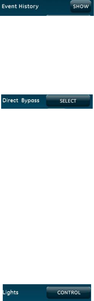
Event history
To view event history:
From the Status & Settings screen, press SHOW next to Event History. The
Event History screen displays a history of all events recorded by the XTi system.
Note: If a # appears in the Event History list, the event was not sent to the central
station.
Direct bypass
To direct bypass a sensor:
1. From the Status & Settings screen, press SELECT next to Direct Bypass.
2. Enter the master code (see Table 10 on page 37).
3. Next to the sensor name, select Bypass to bypass the selected sensor, or Not
bypassed to not bypass the selected sensor.
Panel status
To listen to the panel status:
From the Status & Settings screen, press LISTEN next to Panel Status. The
panel will announce the current status.
To clear the panel status:
From the Status & Settings screen, press CLEAR next to Panel Status.
Lights
To control lights programmed into the system:
1. From the Status & Settings screen, press CONTROL next to Lights.
Note: If no lights are programmed into the system, the following screen will
appear:
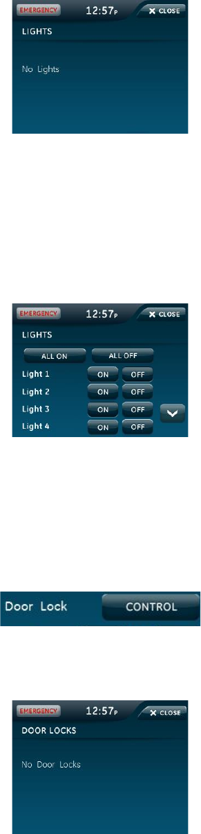
Simon XTi Installation Manual 31
2. From the Lights screen, choose the following options:
• Press ALL ON to turn on all system programmed lights.
• Press ALL OFF to turn off all system programmed lights.
• Press ON next to a designated light to turn that specific light on.
• Press OFF next to a designated light to turn that specific light off.
3. Press CLOSE to exit Lights screen.
Door lock
To control door locks programmed into the system:
1. From the Status & Settings screen, press CONTROL next to Door Lock.
Note: If no door locks are programmed into the system, the following screen
will appear.
2. From the Door Locks screen, choose the following options:
• Press LOCK ALL to lock all system programmed door.
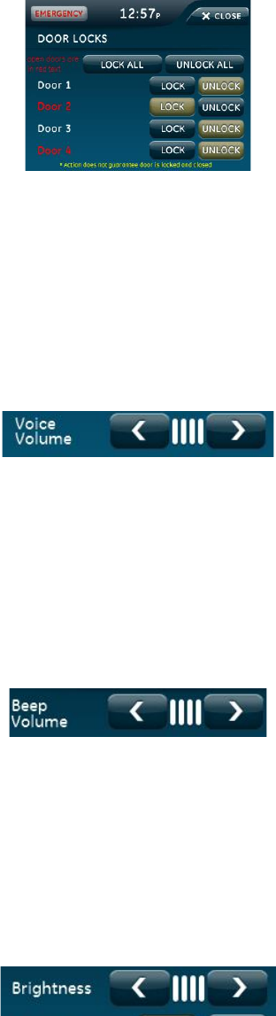
32 Simon XTi Installation Manual
• Press UNLOCK ALL to unlock all system programmed lights.
• Press LOCK next to a designated door to lock that specific door.
• Press UNLOCK next to a designated door to unlock that specific door.
Note: Open doors appear in red text.
3. Press CLOSE to exit Door Locks screen.
Voice volume
To adjust voice volume:
From the Status & Settings screen, next to Voice Volume, press the left arrow to
lower the voice volume and the right arrow to raise the voice volume. The bars
between the arrows register the volume level. No bars is off. Four bars is loudest.
Beep volume
To adjust beep volume:
From the Status & Settings screen, next to Beep Volume, press the left arrow to
lower the beep volume and the right arrow to raise the beep volume. The bars
between the arrows register the volume level. One bar is softest. Four bars is
loudest.
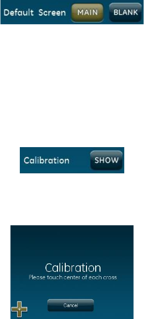
Brightness
To adjust brightness:
From the Status & Settings screen, next to Brightness, press the left arrow to
make the screen less bright and the right arrow to make the screen more bright.
The bars between the arrows register the brightness level. One bar is least
bright. Four bars is brightest.
Simon XTi Installation Manual 33
Default screen
To change the default screen:
From the Status & Settings screen, press MAIN or BLANK next to Default
Screen. To make options visible on a blank screen, touch anywhere on the
screen. The screen will stay visible for two minutes before returning to blank
mode, if untouched.
Calibration
Normally you will not need to calibrate the touch screen, but if the touch screen
icons do not respond correctly, follow the instructions below.
To calibrate the screen:
1. From the Status & Settings screen, press SHOW next to Calibration.
2. Touch the center of the cross using a soft, fine point as it appears in each
corner of the screen.
After the cross in the fourth corner (bottom right) is pressed, the user will be
returned to the Status & Settings screen.
If you cannot access the calibration using the above procedure, use the following
steps:
1. Remove the trim ring from the front of the panel.
2. Press and hold the Reset button (D in Figure 3 on page 14).
3. Press and hold anywhere on the screen.
4. While you are pressing the screen, release the Reset button.
5. Follow the calibration prompts.
34 Simon XTi Installation Manual
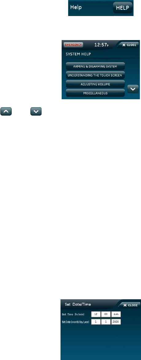
Help
To access the Help screens:
1. From the Status & Setting screen, press the HELP icon.
2. From the SYSTEM HELP screen, choose the help topic to search.
3. Press and to scroll through help topics.
4. Press CLOSE to return to the previous screen.
Set time and date
If the panel loses both AC and battery power, upon power restoral the system
time will reset to midnight and the date will reset to 1 - 1 - 2000, indicating it has
not been set correctly.
Time format is: hour/minute/a.m. or p.m.
Date format is: month/day/year:
To set the time
1. From the Status & Settings screen, select Set Date/Time.
2. Enter access code.
3. From the Set Date/Time screen press the first box to set the hour and press
SAVE.
4. Press the second box to set the minutes and press SAVE.
5. Press a.m/p.m. box to toggle a.m./p.m. setting.
Simon XTi Installation Manual 35
To set the date
1. From the Set Date/Time screen press the first box in the second row to set
the month and press SAVE.
2. Press the second box to set the day and press SAVE.
3. Press the third box and enter the year and press SAVE.
4. Press CLOSE repeatedly to exit.
Version
To display the system’s firmware version, touch screen version, and copyright
information, scroll until the display shows Version on the bottom of the screen.

36 Simon XTi Installation Manual
Programming
To enter programming:
1. From the Status & Settings screen, press to scroll to the Programming
option.
2. Press Enter.
3. Enter the dealer or installer code (see Table 9 below) and press OK.
Note: You have four seconds between number presses to enter the code or
you will be returned to the home screen.
Note: Do not remove the panel power within 30 seconds of exiting program
mode.
Table 9: Simon XTi programming codes
Code
Description
Dealer code
You can use the dealer code to program all system functions,
including high-security options that are not accessible with the
installer code if it is different from the dealer code. Depending on
how the access code is set, the default dealer access code is
654321, 54321, 4321 (factory default), or 321. This code can be
used for all programming.
Installer code
Depending on how the access code is set, the default installer code
is 654321, 54321, 4321 (factory default), or 321. This code is limited
to changing all but the following: Dealer code, code length,
downloader code, phone lock, phone #1, phone #2, phone 1 report
mode, phone 2 report mode, HW1 function.
The following sections describe the programming options in the Programming
submenus.
Simon XTi Installation Manual 37
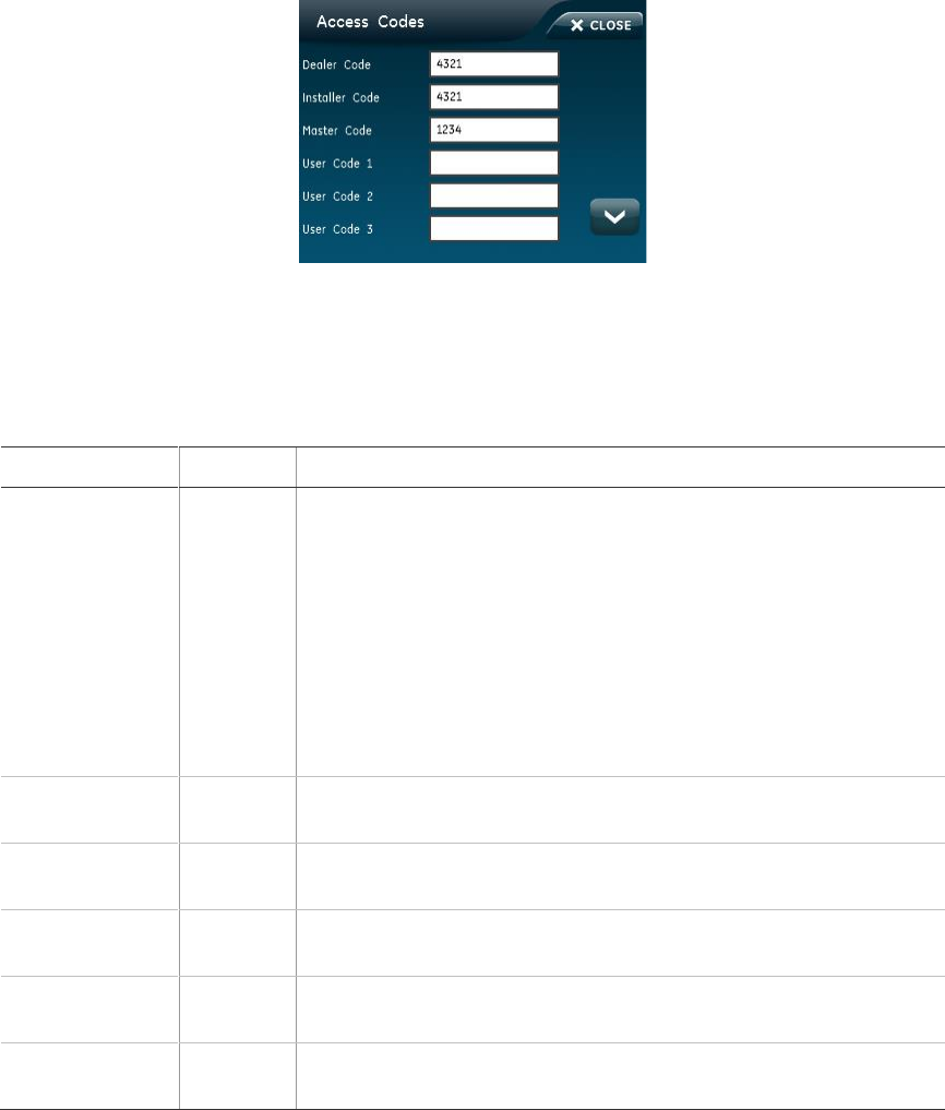
Access codes
To add/edit access codes:
1. From the Programming screen, press ACCESS CODES.
2. To add or edit an access code, press the white field next to the access code.
3. Enter the new/edited code on the numbered keypad and press SAVE.
4. Press CLOSE repeatedly to exit menus
Table 10: Access Codes menu
Function
Default
Description
Dealer code
4321
You can use the dealer code to program all system options,
including high-security options that are not accessible with the
installer code if it is different from the dealer code. Changing the
dealer code to differ from the installer code will prevent the
installer from viewing certain fields.
If you change the dealer code and enter program mode with the
installer code, the installer will no longer be able to see the
following: code length, downloader code, phone lock, phone #1,
phone #2, phone 1 report mode, phone 2 report mode, HW1
function.
Installer code
4321
You can use the installer code to program most installer options,
except for high-security dealer options.
Master code
1234
You can use the master to arm/disarm, enter user programming,
and bypass sensors.
User codes 1 to
8
Blank
You can use the user codes to arm/disarm the system.
Duress code
Blank
Use the duress code in place of the master or user code to cause
a silent alarm.
Code length
Four
digits
Codes can be three to six digits long.
38 Simon XTi Installation Manual
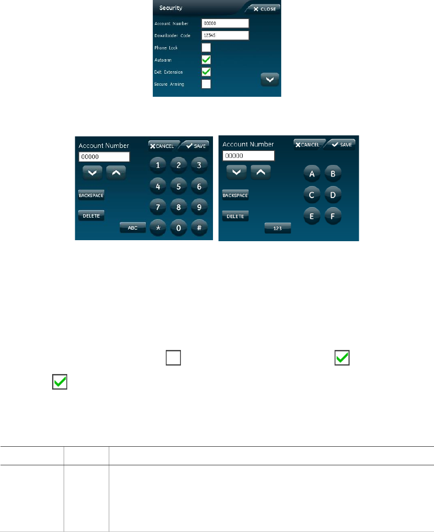
Security
To add/edit account number or downloader code:
1. From the Programming screen, press SECURITY.
2. To add or edit an account number or downloader code, press the white field
next to account number or downloader code.
3. Enter the new/edited code on the numbered keypad and press SAVE.
Note: The account number can be alphanumeric. To enter letters, press the
ABC icon. To enter numbers press the 123 icon.
To edit phone lock, auto arm, exit extension, secure arming, no arm on low
battery, quick exit, and downloader enable options:
1. From the Programming screen, press SECURITY.
2. To turn on an option, press . To turn off an option, press .
Note: indicates the option is turned on.
3. Press CLOSE repeatedly to exit menus.
Table 11: Security menu
Function
Default
Description
Account
number
00000
Lets you program up to a 10-character alphanumeric account number or
delete an existing account number by pressing Disarm. You can enter
numerical digits sequentially. Account numbers with letters A through F,
or numbers 0 through 9 (or a combination of those letters and numbers)
are only supported.

Simon XTi Installation Manual 39
Function
Default
Description
Downloader
code
12345
Lets you set a unique five-digit code that is required for initiating
Enterprise Downloader sessions. The code must be five digits long and
can range from 00000 to 99999. The downloader code must match the
downloader access code in the Enterprise account to perform Enterprise
sessions.
Phone lock
Off
Prevents resetting of phone/reporting related options when a memory
clear is preformed (on) or resets these options to their default values
when a memory clear is performed (off). The following are not reset
when on: account number, dealer code, code length, call wait cancel,
phone numbers 1 and 2, phone report modes 1 to 4, phone lock,
downloader phone number and downloader code.
Auto arm
On
Determines how long the system protests (announces open/failed
sensors) when attempting to arm with open/failed sensors, before
bypassing these sensors and automatically arming the rest of the
system. The panel protests an arming attempt when it has not received
a restore (close) signal from sensors learned into restore-specific sensor
groups. Sensors learned into group 26 (fire) cannot be bypassed.
When this option is on, the panel announces all open/failed sensors
repeatedly for four minutes, then automatically bypasses the open
sensors and arms the rest of the system. If a sensor is opened during
the exit delay and then left open, the panel will go into alarm after the
exit delay has expired. This option must be on for unvacated premises
and exit extension to work correctly.
When the option is off, the panel displays all open/failed sensors once,
then automatically bypasses the open sensors and arms the rest of the
system after the exit delay has expired. If other sensors are opened
during the exit delay, they will also be bypassed if left open.
If group 13 (instant perimeter) sensors are opened during the exit delay,
the panel goes into immediate alarm.
Exit extend
On
Determines whether the panel restarts the exit delay time if you enter
the armed premises during the initial exit delay period (on), or not (off).
Turning on this feature allows you to reenter during the exit delay period,
without disarming and then rearming the system. Turning off this feature
requires you to disarm and rearm the system.
Note: Auto arm must be on for this option to work.
Secure
arming
Off
Determines whether an access code is required when arming the
system (on), or not (off). This option does not affect key fob arm/disarm
operation.
No arm on
low battery
Off
Determines whether the system protests arming if a low CPU battery
condition exists (on), or not (off).
40 Simon XTi Installation Manual
Function
Default
Description
Quick exit
Off
Determines whether pressing Disarm when the system is armed
activates the exit delay time to allow exit and reentry without disarming
the system (on), or not (off). This feature is useful if you want to step
outside briefly and return. If the system is armed and you press Disarm,
the panel announces Exit Time is On, and sounds exit delay beeps. This
allows a designated entry/exit door to open for up to two minutes without
causing alarm. When the door is closed, the beeps stop and the door is
armed again.
Downloader
enable
On
Enables programming of system options with downloader software.
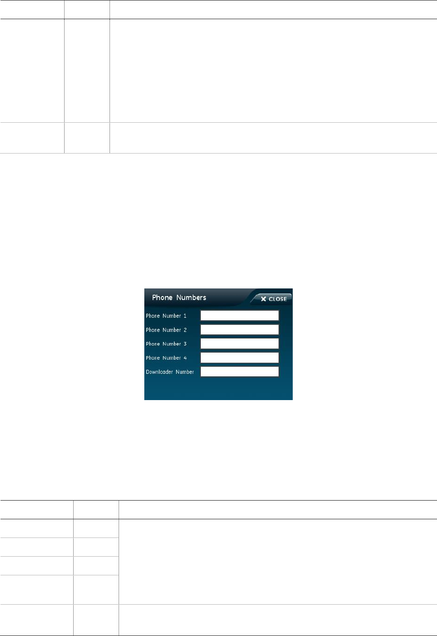
Phone numbers
To add/edit phone numbers:
1. From the Programming screen, press PHONE NUMBERS.
2. To add or edit a phone number, press the white field next to the phone
number.
3. Enter the new/edited phone number on the numbered keypad and press
SAVE.
4. Press CLOSE repeatedly to exit menus.
Table 12: Phone Numbers menu
Function
Default
Description
Phone #1
Blank
Lets you program up to a 26-digit central monitoring station receiver/
voice event notification phone number for monitored systems. Phone
digits can be 0 to 9, *, #, or a pause (P).
To delete the phone number, press Delete on the keypad while editing
a phone digit. To add a pause to the phone number, press Pause on
the keypad.
Phone #2
Blank
Phone #3
Blank
Phone #4
Blank
Downloader #
Blank
Lets you program up to a 26-digit phone number for the Enterprise
Downloader.
Simon XTi Installation Manual 41
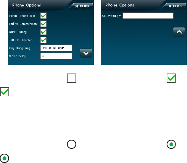
Phone options
To edit manual phone test, fail to communicate, DTMF dialing, and 300 BPS
enabled options:
1. From the Programming screen, press PHONE OPTIONS.
2. To turn on an option, press . To turn off an option, press .
Note: indicates the option is turned on.
3. Press CLOSE repeatedly to exit menus.
To edit ring hang ring option:
1. From the Phone Options screen, press the white field next to Ring Hang Ring.
2. To turn on an option, press . To turn off an option, press .
Note: indicates the option is turned on.
3. Press CLOSE repeatedly to exit menus.
To edit dialer delay option:
1. From the Phone Options screen, press the white field next to Dialer Delay.
2. Enter the new/edited dialer delay time on the numbered keypad and press
SAVE.
3. Press CLOSE repeatedly to exit menus.
To edit the call waiting # option:
1. From the Phone Options screen, press the white field next to Call Waiting #.
2. Enter the new/edited call waiting # on the numbered keypad and press SAVE.
3. Press CLOSE repeatedly to exit menus.

42 Simon XTi Installation Manual
Table 13: Phone Options menu
Function
Default
Description
Man phone
test
On
Determines whether you can perform a manual communication test to
verify communication to a central station/voice dial (on), or not (off). If
you have all four phone numbers programmed, it should send a test
report to all four before showing that the test is okay.
FTC
On
Determines whether the panel and interior sirens sound trouble beeps
if it is unable to successfully send a report to a central station (on), or
not (off).
DTMF dial
On
Determines whether the panel uses DTMF (on) or pulse (off) for
dialing programmed phone numbers.
300 bps
enabled
On
Determines whether the baud rate used by the panel for central
station communication is 300 bps (on), or 110 bps (off).
Ring hang ring
RHR or
10
Rings
Determines when the panel answers a remote phone access or
Enterprise call. Depending on whether an answering machine exists
at the panel location, offsite access to the panel can be done with a
series of phone calls or just one. For offsite access where an
answering machine does not exist, the user or Enterprise operator
simply calls the panel location once and listens for 10 rings. The panel
should answer after the tenth ring.
For offsite access where an answering machine exists, the user or
Enterprise operator must call the panel location, and then let the
phone ring once and hang up. Wait at least 10 seconds but not more
than 40, and then call the panel location again. The panel should
answer on the first ring.
Ring/hang/ring setting number and sequence of rings after which the
panel answers:
• RHR or 10 Rings = Ring/hang/ring or ten rings
• RHR(2) or 10 Rings = Ring/hang/ring/hang/ring or ten rings
• RHR(3) or 10 Rings = Ring/hang/ring/hang/ring/hang/ring or ten
rings
• 10 Rings = Ten rings
• RHR = Ring/hang/ring
• RHR(2) = Ring/hang/ring/hang/ring
• RHR(3) = Ring/hang/ring/hang/ring/hang/ring
• Off = Disabled, no remote (offsite) access
Dial delay
30
seconds
Determines whether the panel delays dialing programmed phone
numbers before sending report (on).
If opening (disarming) reports is on, the panel does not delay dialing if
the system is disarmed before the delay time expires. The panel dials
immediately for both the alarm and opening report.
Regardless of this option setting, the panel always dials immediately
for fire alarms, AC power failure, and low battery reports.
Simon XTi Installation Manual 43
Function
Default
Description
Call waiting #
Off
The call waiting number is dialed by the panel before a phone number
to disable call waiting. If the end-user has call waiting, we recommend
you change this option from its default.
CAUTION: Changing this option from its default without call waiting
will prohibit the panel from calling the central station.
The call waiting code is programmed the same way as a dialer
number.
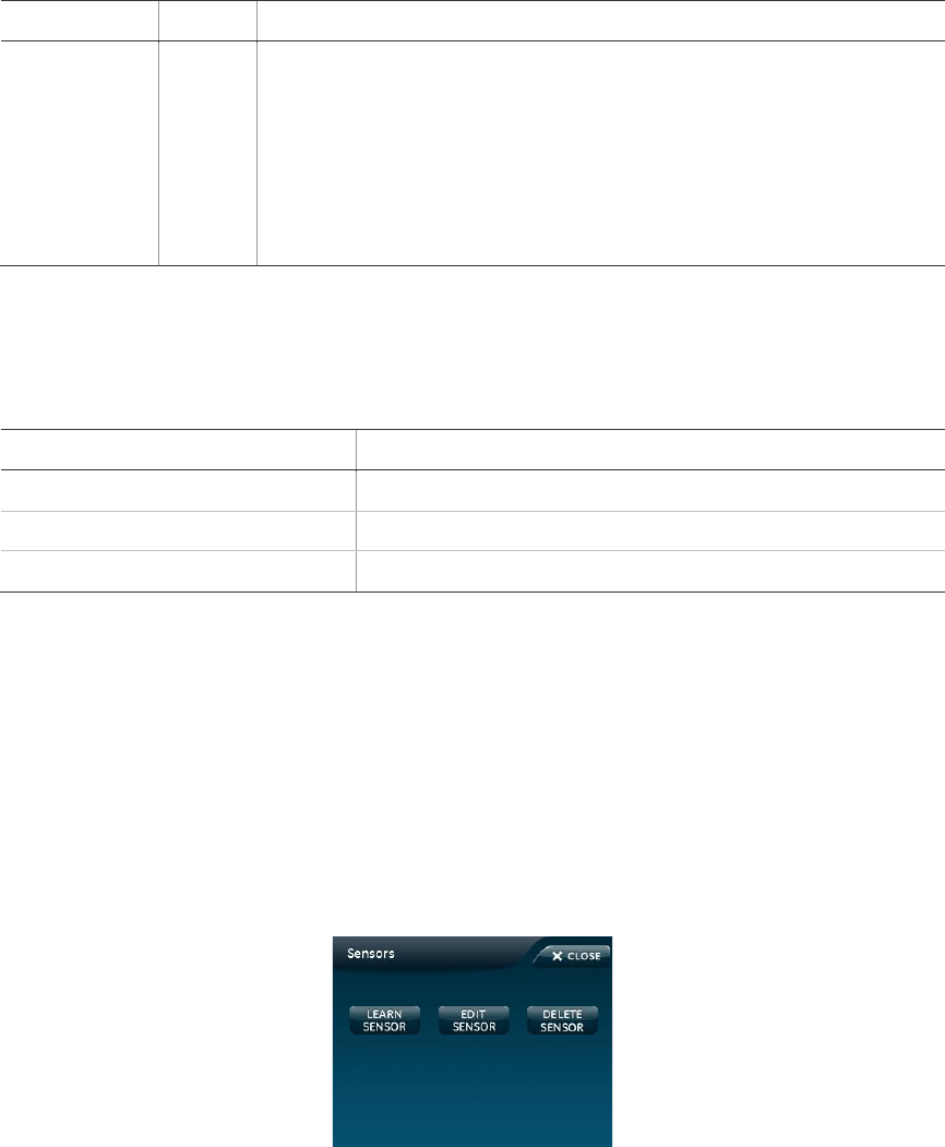
Sensors
Table 14: Sensors menu
Function
Description
Learn sensors
Adds (learns) sensors to panel memory.
Delete sensors
Deletes sensors from panel memory.
Edit sensors
Edits sensor information in panel memory.
The following instructions tell how to add (learn) sensors, touchpads, and other
system devices into panel memory. The panel recognizes a sensor when you
press a sensor program button, press and release a tamper switch, press a
sensor test button, or put a sensor into alarm. Table 15 on page 45 below
describes the programming method for each device.
To learn (program) and edit a sensor:
1. From the Programming screen, press SENSORS.
2. From the Sensors screen, press LEARN SENSORS.
3. Press the sensor program button or release the sensor tamper switch. The
Edit Sensor screen will appear.

44 Simon XTi Installation Manual
4. To change the sensor number, press EDIT next to Sensor Number, enter the
new sensor number, and press SAVE.
Note: The sensor number can only be edited during sensor learning.
5. To change the sensor group, press EDIT next to Sensor Group, enter the new
sensor group, and press SAVE.
6. To change the sensor name, press EDIT next to Sensor Name, press EDIT
next to the item number to be changed, scroll through and press the correct
name from the list, and press SAVE.
Note: Default the screen to List and not Keypad. This gives the user the list of
stored sensor names.
7. Press SAVE to save the changes.
8. Press CLOSE to return to the Sensors screen.
To delete a sensor:
1. From the Programming screen, press SENSORS.
2. From the Sensors screen, press DELETE SENSORS.

Simon XTi Installation Manual 45
3. Press DELETE next to the sensor to be deleted.
4. Press CLOSE to return to the Sensors screen.
Mounting Recommendations:
• Where possible, install sensors within 100 feet (30 m) of the receiver. While a
transmitter and receiver combination may have an open-air range of 500 feet
(152 m) or more, the environment at the installation site may have a
significant effect on operational range. Changing a sensor or receiver location
can improve wireless communication.
• Avoid mounting sensors or receivers in areas where they will be exposed to
moisture or where the operating temperature range will exceed the specified
range (10 to 120 °F).
• Avoid mounting the sensor or receiver in areas with a large quantity of metal
or electrical wiring. For example: within 1 meter of AC distribution panel (fuse
box), HVAC duct work.
• Avoid mounting the sensor or receiver directly on metal.
• The Simon XTi system should not be mounted within 3 meters of any other
RF equipment (RF music system transmitter, wireless router/modem, etc.).
Note: Refer to specific sensor installation instructions for complete operation and
testing details.
Table 15: Device programming
Device
To program
Door/window sensor
Press the button on the top of the sensor (cover removed) or
trip the tamper.
Motion sensor
Press the button on the back of the sensor (mounting plate
removed) or trip the tamper.
Smoke detector
Trip the tamper, press the test button, remove the detector from
its base, or put the smoke detector into alarm.
Hardwired sensor
Separate the sensor from its magnet.
Glassbreak sensor
Trip the tamper switch on the sensor.
CO alarm
Trip the wall tamper by removing the sensor body from the
mounting plate.
Simon XT talking touch screen
1. Press the Settings icon.
2. Press the Down arrow until the Clear and Enroll icon
appears.
3. Press the Clear and Enroll icon. The touch screen should
indicate it is waiting for enrollment.
Simon XT talking touchpad
Press the Lights off button on the touchpad six times in rapid
succession. On the sixth press, the touchpad makes a longer
beep.
46 Simon XTi Installation Manual
Device
To program
Key fob
Press the Lock and Unlock buttons at the same time.
Note: If you are installing a sensor on a gun case, jewelry box, or a similar case,
and the sensor is active in level one, you must bypass the sensor to avoid putting
the panel into alarm when the sensor and the magnet are separated.
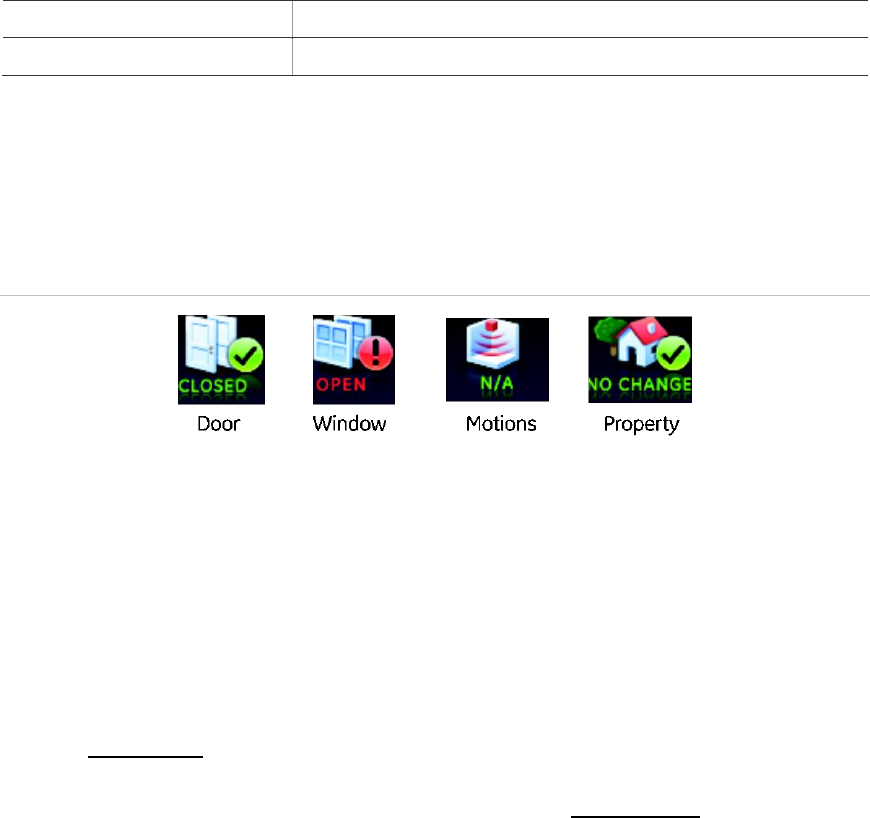
Sensor association with the graphical interface icons
Figure 16: At a glance icons
The at-a-glance icons (see Figure 16 above) Door, Window, Motions, and
Property, found on the Simon XTi (and remotely connected Talking Two-Way
Touch Screens) are associated with sensors, given a set of rules.
• The default state for a disassociated at-a-glance icon is N/A.
• Any learned-in sensor (regardless of type or group) with a sensor name that
includes the word “window” or “door” from the text library will automatically
associate respectively with the at-a-glance Doors and Window icons.
Example, a door-window sensor learned in, and physically attached to a door,
with Front Door as its name, group 10 as its type will be associated with the
Doors icon on the graphical interface. In contrast, a door-window sensor
learned in, and physically attached to a door, with Utility Room as its name,
group 10 as its type will NOT be associated with the Doors icon. It would be
associated with the property icon on the graphical interface.
• Any learned-in sensor (regardless of type or name) with a group type of 17,
18, 20, or 28, will associate with the at-a-glance Motions icon. Depending on
the location of the screen, a typical use for this feature would be to identify
motion before entering the building (if placed in a garage), or alerting to
motion downstairs from the master bedroom, if the system wasn't armed. The
Motion icon will clear after 10 minutes of inactivity.
• Any sensor that is not associated with the Doors, Window, or Motions icons
based on the preceding rules is automatically associated to a Property icon.
• The Property Icon supports two different sensor group types restoral, and
non-restoral. Restoral based sensors provide clear indication of event start
and stop. An example is a flood sensor. The flood sensor will associate with
the Property icon and continue to report as “Changed" when water is detected
and remains detected by the sensor. When the water condition clears, the
Simon XTi Installation Manual 47
Property icon Open will clear. Non-restoral based sensors, provide indication
of event start, but not stop. An example is tilt switch/garage door sensor that
determines if something that it is attached to the sensor, like a boat trailer has
moved. The tilt sensor will associate with the Property icon and will report as
"Changed" when movement is detected the first time. Upon user
acknowledgement of the event by pressing the Property icon, the Changed
state is returned to No Change.
Common associations of icons and sensors
• Exteriors motions for use in driveways for non-reporting, informational
purposes can be associated with the Property icon using group types 40 or
43.
• Water sensors learned group 29 will alarm immediately upon activation; if
informational detection is desired without reporting, use group 40.
• Freeze sensors learned group 38 will alarm immediately upon activation; if
informational detection is desired without reporting, use group 40.
• Tilt sensors can be used as a means to provide asset monitoring associated
with the Property icons with the use of group type 43.
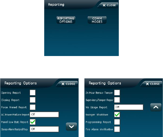
Reporting
To turn on/off reporting options:
1. From the Programming screen, press REPORTING.
2. From the Reporting screen, select REPORTING OPTIONS.

48 Simon XTi Installation Manual
3. To turn on an option, press . To turn off an option, press .
Note: indicates the option is turned on.
4. Press CLOSE to return to the Reporting screen.
Table 16: Reporting menu
Option
Default
Description
Opening reports
Off
Determines whether the panel sends opening reports to a central
station whenever the system is disarmed (on), or not (off). The
User number will be reported as zone number. Key fobs learned
into zones 1 to 40 will report as that zone.
Dealer code = 44, Installer code = 45, Master code = 46, User
code 1 = 47, User code 2 = 48, User code 3 = 49, User code 4 =
50, User code 5 = 51, User code 6 = 52, User code 7 = 53, User
code 8 = 54, Duress code = 55
Closing reports
Off
Determines whether the panel sends closing reports to a central
station whenever the system is armed (on), or not (off). The User
number will be reported as the zone number. Key fobs learned
into zones 1 to 40 will report as that zone.
Dealer code = 44, Installer code = 45, Master code = 46, User
code 1 = 47, User code 2 = 48, User code 3 = 49, User code 4 =
50, User code 5 = 51, User code 6 = 52, User code 7 = 53, User
code 8 = 54, Duress code = 55
Force armed
Off
Determines whether the panel sends by force armed report to a
central station if the user bypasses protesting sensors (indirect
bypass) when arming the system (on), or not (off).
AC Power failure
Report
Off
Determines whether the panel sends AC power failure reports to a
central station after the programmed time expires. The time can
be set from 005 to 254 minutes.
When the panel is without AC power for 30 seconds, the panel
screen turns off.
When the panel is without AC power for the programmed time, an
AC power failure is reported.
The panel reports an AC power restoral when AC power returns to
the panel.
Panel Low Battery
Report
On
Determines whether the panel sends a low CPU battery report to
the central station when the panel backup battery voltage drops.
Sen alarm restore
Off
Determines whether the panel reports sensor alarm restoral (on),
or not (off). Setting when restoral is reported:
• Sensor Close - Immediately after sensor is closed or restored
after dial delay
• Siren Timeout - After siren timeout expires if sensor is
restored
• System Disarm - When system is disarmed if sensor is
restored.
• Off

Simon XTi Installation Manual 49
Option
Default
Description
24-hour sensor
tamper
Off
Determines whether the system (armed or disarmed) goes into
and reports an alarm anytime a sensor tamper switch is tripped
(on), or only when the system is armed and a tamper switch of an
armed sensor is tripped (off).
Supervisory/tamper
Off
Determines whether the panel sends supervisory reports to a
central station as a tamper (on), or a supervisory (off).
Note: This option is typically used only in Europe where a
supervisory condition is required to report as a tamper.
No usage
Off
Determines whether the panel sends a No Usage report to the
central station if the user has not operated the system before the
programmed time expires (on), or not (off). The timer starts each
time the system is disarmed.
Note: This is a customer service feature that alerts the central
station if a customer is not using their security system. The
service provider can then contact the customer to find out why the
system is not being used, and help correct any problems for the
customer.
Swinger shutdown
On
This setting determines if a sensor or zone will go into alarm only
once during an arming period (an active arming level) and will not
be active again until the alarm is canceled (swinger Shutdown is
enabled) or the sensor or zone will always be active and will go
into alarm multiple times during an arming period (an active
arming level) without canceling the alarm (Swinger Shutdown is
disabled).
On = 1 trip
Off = unlimited trips
Note: Swinger shutdown does not affect Smoke, Fire, Carbon
Monoxide, and Environmental sensors learned into groups 26
(Fire/Smoke), 29 (Freeze), 34 (CO), and 38 (Water).
Programming
report
Off
Determines whether the panel sends a report to the central station
anytime the programming mode is entered/exited (on), or not at all
(off). The panel sends a report whenever the dealer (Utility 1) or
installer (Utility 2) code is used to enter programming mode and
another report is sent when the programming session ends.
Fire Alarm
Verification
Off
If this option is off, the panel immediately reports to the central
station when a smoke detector goes into alarm.
With this option on, if a single smoke detector goes into alarm, the
panel will not report for 60 seconds unless another smoke
detector goes into alarm. If the first smoke detector is cleared of
alarm within the first 60 seconds, no report will be sent to the
central station unless it or a second smoke detector goes into
alarm within the panel siren timeout period (5 minutes).
To edit communication modes options:
1. From the Programming screen, press REPORTING.
2. From the Reporting screen, select COMM MODES.
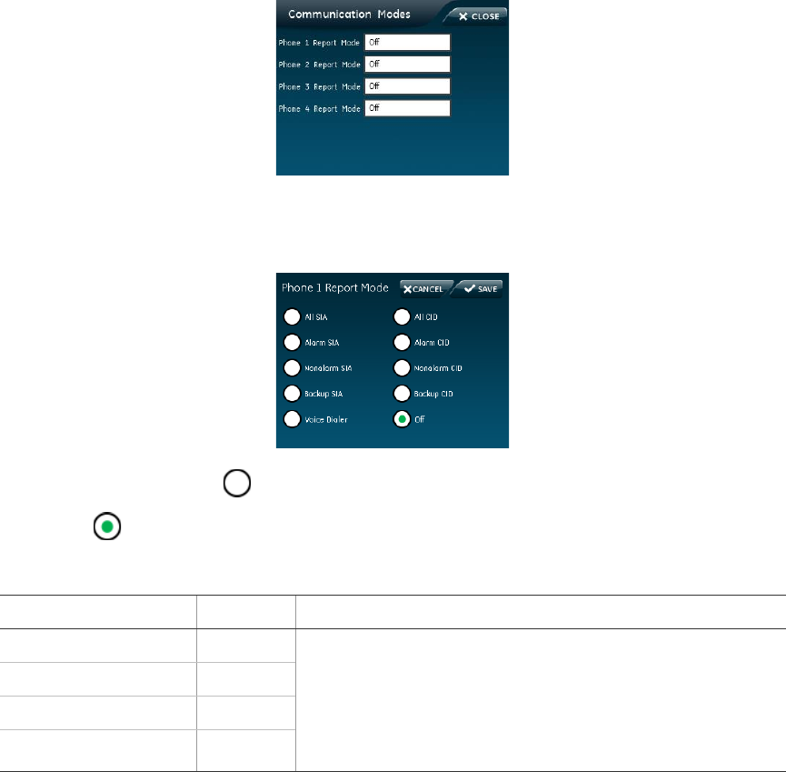
50 Simon XTi Installation Manual
3. From the Communication Modes screen, press the white field next to the
correct Phone Report Mode to edit.
4. Select, by pressing next to the correct option.
Note: indicates the option is turned on.
Table 17: Communication modes
Option
Default
Description
Phone 1 report mode
Off
Determines how the panel sends a report to the central
station for each of the phone numbers programmed.
The options are: All SIA, All CID, Alarm SIA, Alarm CID,
Nonalarm SIA, Nonalarm CID, backup SIA (phone failure
backup), Backup CID (phone failure backup), Voice dialer,
Off
Phone 2 report mode
Off
Phone 3 report mode
Off
Phone 4 report mode
Off
Alarms include: Fire, Intrusion, Emergency, Silent, and Alarm Cancels.
Nonalarms include: No Activity, Openings, Closings, Fail-to-Open, Fail-to-Close,
Force Armed, AC Power Failure, CPU Low Battery, and Trouble Restoral.
Timers
To edit timer options:
1. From the Programming screen, press TIMERS.
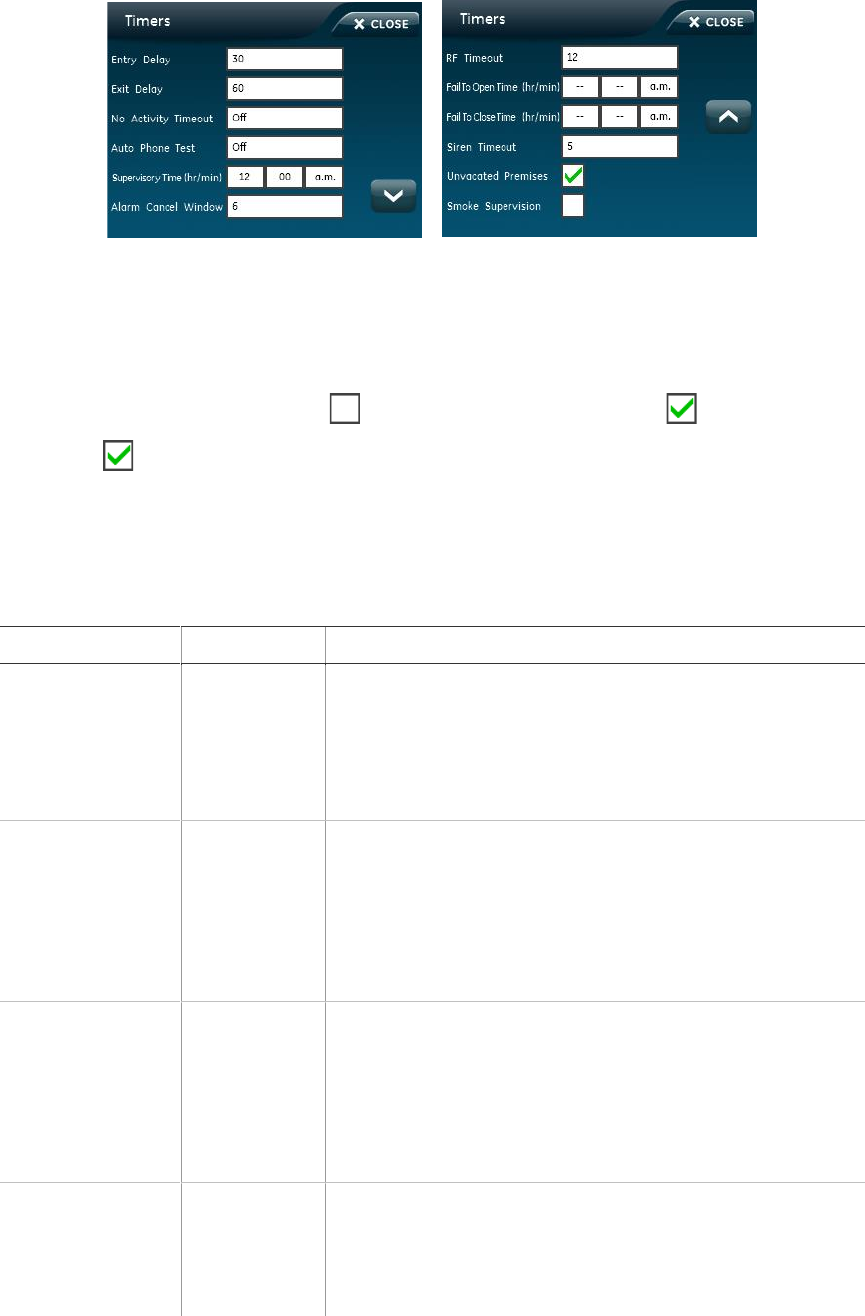
Simon XTi Installation Manual 51
2. From the Timers screen, press the white field next to the Timer option to edit.
3. Enter the value on the numbered keypad.
OR
To turn an option on, press . To turn an option off, press .
Note: indicates the option is turned on.
4. Press SAVE to save the changes.
5. Press CLOSE to return to the Programming screen.
Table 18: Timers menu
Function
Default
Description
Entry delay
030 seconds
Determines how much time you have to disarm the system
after entering the armed premises through a designated
delay door, before an alarm occurs. Beeps sound during the
entire delay time to remind you to disarm the system. When
turned on, the entry delay can be set from 030 to 240
seconds.
Exit delay
060 seconds
Determines how much time you have to leave the premises
through a designated delay door after arming the system.
Beeps sound after arming the system to remind you to
leave the armed premises. If a delay door is opened after
the exit delay expires, the entry delay begins. If you arm the
system with no delay and open a delay door after the exit
delay expires, an alarm occurs.
No activity tm
Off
Determines whether the panel sends a no activity report to
a central station when the programmed time elapses (on),
or if the feature is disabled (off). No activity means the
control panel, remote handheld, and key-chain touchpad
buttons have not been pressed and sensors have not been
tripped within a specified time (except sensors in group 25
and 43). The timeout can be set from 02 to 24 hours.
Auto phone test
Off
Determines whether the panel automatically performs a
periodic phone test (on), or not (off). The test interval can be
from 001 to 254 days. The time of day the panel performs
the test is determined by the supervisory time, which must
be turned on for this feature to work.

52 Simon XTi Installation Manual
Function
Default
Description
Supervisory time
12:00am
Determines when the panel reports supervisory conditions
(sensor failures) and automatic phone tests to the central
station. The panel clock must be set to the correct time for
this option and the automatic phone test to work correctly.
Alarm cancel
006 minutes
Sets the time frame that determines whether the panel
reports an alarm cancel message to the central station. If
the system is disarmed from an alarm state within the
programmed time, the panel sends an alarm cancel
message to the central station. An alarm cancel message is
not reported if the system is disarmed after the programmed
time expires.
The time can be set from 006 to 255 minutes. When set to
255, the panel always reports alarm cancel messages.
Turning off this option disables alarm cancel reporting.
RF time-out
12 hours
Determines the period during which the panel must receive
at least one supervisory signal from learned sensors before
identifying a sensor failure and sounding trouble beeps. Any
sensor failure is reported immediately and again at the
supervisory time. The timeout can be set from 02 to 36
hours. Entries must be two digits.
Fail-to-open time
Off
Determines whether the panel sends a fail-to-open report to
a central station if the system has not been disarmed by the
programmed time (on), or not (off). System time must be set
correctly for this feature to work.
Fail-to-close time
Off
Determines whether the panel sends a fail-to-close report to
a central station if the system has not been armed by the
programmed time (on), or not (off). System time must be set
correctly for this feature to work.
Siren time-out
005 minutes
Determines how long sirens sound alarms if no one is
present to disarm the system. The time can be set from 002
to 254 minutes. When this feature is turned off, sirens
sound alarms until the alarm is canceled (system disarmed).
Unvacated
premises
On
Unvacated premises is a feature that determines whether
the system automatically arms down to level 2 (doors and
windows) if you arm the system to level 4 (doors, windows,
and motion sensors) without opening or closing a perimeter
door (on), or remains at the armed level chosen (off). This
feature does not work from a key fob. Autoarm must be on
for this feature to work.
Smoke supervision
Off
Determines how often the panel must receive supervisory
signals from the smoke sensors. If this option is on, the
panel must receive at least one supervisory signal from
smoke sensors every four hours or it will identify a sensor
failure and sound trouble beeps. If this option is off, the time
for receiving supervisory signals is determined by RF
timeout.
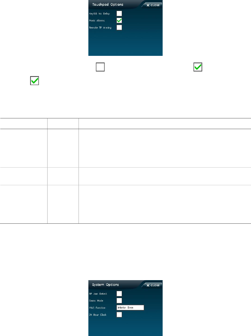
Simon XTi Installation Manual 53
Touchpad options
To edit touchpad options:
1. From the Programming screen, press TOUCHPAD OPTIONS.
2. To turn an option on, press . To turn an option off, press .
Note: indicates the option is turned on.
3. Press CLOSE to return to the Programming screen.
Table 19: Touchpad Options menu
Function
Default
Description
Keyfob no delay
Off
Determines whether a key fob arms the system with no delay (on),
or not (off). When this feature is on, you must disarm the system
before entering the premises, since it is disabling the entry delay.
If the remote touchpad arming option is on, key fobs cannot
disarm the system and will cause an alarm upon entering.
Panic alarms
On
Determines whether the panel panic icons (police, panic, and fire)
activate alarms when pressed (on), or not (off).
Remote TP arm
Off
Determines whether key fobs and remote touchpads can disarm
the system only during exit and entry delays (on), or arm and
disarm the system anytime (off). If this option and the key fob no
delay option are on, you cannot enter and/or disarm using remote
touchpads without causing an alarm.
System options
To edit system options:
1. From the Programming screen, press SYSTEM OPTIONS.

54 Simon XTi Installation Manual
2. For RF jam detect, demo mode, and 24 hour clock; to turn an option on, press
. To turn an option off, press . Go to Step 5.
OR
Press the white field next to the HW1 function option to edit.
3. Select an option on the HW1 function screen by pressing next to the
correct option.
Note: indicates the option is turned on.
4. Press SAVE.
5. Press CLOSE to return to Programming screen.
Table 20: System Options menu
Function
Default
Description
RF jam
detect
Off
Determines whether the panel checks for and reports RF
interference/jam to the central station (on), or not (off). If this option is on
and the panel receives a constant 319.5 MHz signal, the panel reports
the condition to the central station. If this option is off, the panel does
not detect an RF jam.
Demo mode
Off
Determines whether the panel operates as a demonstration model (on)
or a standard panel (off). Turning on this feature disables low battery
supervision. With this option on, the panel is not testing battery
supervision.
HW1
function
Interior
Siren
Determines how the HW1 I/O output will function:
• Off = no output
• Interior Siren = interior siren output
• Armed = output activated when armed
• Disarmed = output activated when disarmed
• FTC = fail to communicate output, activates when fail to
communicate condition occurs (the fail to communicate option must
be on)
• Alarm = alarm output activated when panel is in alarm
• Extior Siren = Extior Siren output
24-hour
clock
Off
Determines whether the panel uses a 24-hour clock (on), or a 12-hour
clock (off).
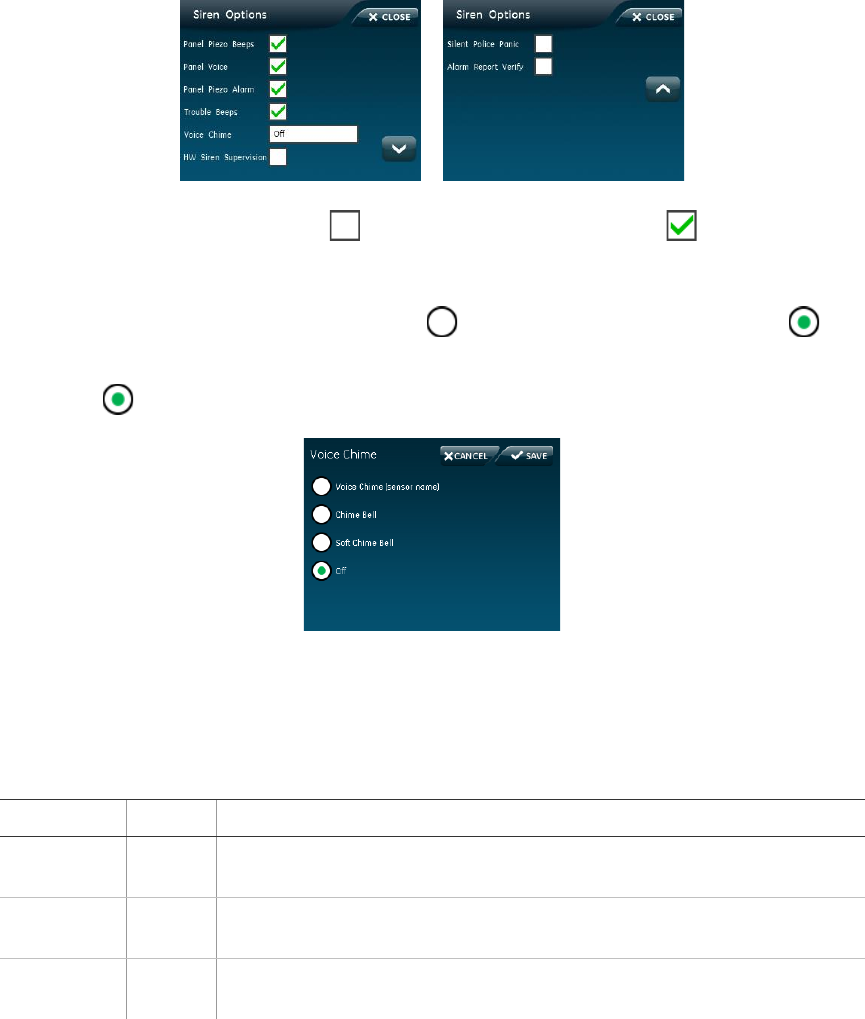
Simon XTi Installation Manual 55
Siren options
To edit siren options:
1. From the Programming screen, press SIREN OPTIONS.
2. To turn on an option, press . To turn off an option, press . Go to Step 5.
OR
Press the white field next to the Voice Chime option to edit.
3. From the Voice chime screen, press to turn an option on and press to
turn an option off.
Note: indicates the option is turned on.
4. Press SAVE.
5. Press CLOSE to return to the Programming screen.
Table 21: Siren Options menu
Function
Default
Description
Panel Piezo
beeps
On
Determines whether the panel piezo produces beeps based on system
activity (on), or is silent (off).
Panel voice
On
Determines whether the panel announces arming level changes (on), or
not (off).
Panel piezo
alarm
On
Determines whether the panel piezo emits alarm sounds (on), or not
(off).
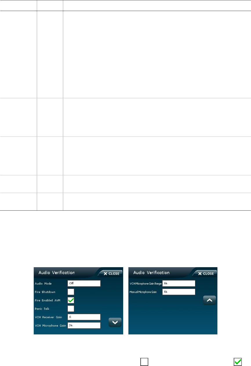
56 Simon XTi Installation Manual
Function
Default
Description
Trouble
beeps
On
Determines whether the panel and hardwired interior sirens sound six
beeps every minute when a trouble condition occurs (on), or not (off).
The following conditions cause trouble beeps: AC power failure (when
AC power failure report is on), low CPU battery, sensor failure
(supervisory), sensor trouble (low battery, tamper, etc.), fail to
communicate, restoration of power, no activity timer has timed out
(trouble beeps continue for 5 minutes and if the panel does not see
activity, trouble beeps stop and the panel reports no activity to the
central station).
You can silence trouble beeps by arming or disarming the system or by
pressing the STATUS icon. Trouble beeps resume later if the trouble
condition is not cleared.
Voice chime
Off
Determines whether the panel announces the sensor name.
• Voice Chime = sensor name
• Chime Bell = loud ding-dong bell
• Soft Chime Bell = soft ding-dong bell
• Off = no sound
HW siren
sup
Off
Determines whether the panel monitors hardwired sirens for open
conditions (on), or not (off). If this option is turned on, sirens connected
to the panel terminals require an EOL resistor in the wire circuit. If this
option is turned off, EOL resistors are not required whether sirens are
connected or not.
Silent police
panic
Off
Determines whether pressing the panel police icon causes an audible
(off) or silent (on) alarm.
Alarm report
verify
Off
Determines whether the panel verifies successful alarm reports to the
central station by displaying “Phone comm OK” (on), or not (off).
Audio verification options
To edit audio verification options:
From the Programming screen, press AUDIO VERIFICATION.
To edit fire shutdown, fire enabled AVM, and panic talk options:
1. From the Audio Verification screen, press to turn an option on. Press to
turn an option off.
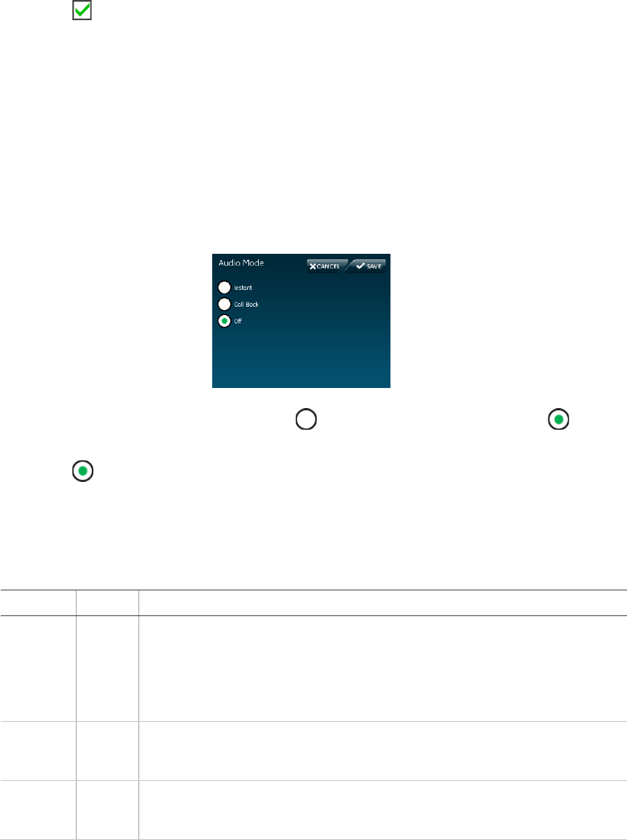
Simon XTi Installation Manual 57
Note: indicates the option is turned on.
2. Press CLOSE to return to the Programming screen.
To edit VOX and manual microphone gain options:
1. From the Audio Verification screen, press the white field next to the option.
2. On the keypad, enter the value and press SAVE.
3. Press CLOSE to return to the Programming screen.
To edit audio mode option:
1. From the Audio Verification screen, press the white field next to audio mode.
2. From the Audio Mode screen, press to turn an option on and press to
turn an option off.
Note: indicates the option is turned on.
3. Press SAVE.
4. Press CLOSE to return to the Programming screen.
Table 22: Audio Verification Options menu
Function
Default
Description
Audio
mode
Off
Determines the audio mode.
• 1 (Instant) = Panel stays online with central station for an instant audio
session.
• 2 (Callback) = Panel hangs up and waits for a callback from the central
station operator before starting an audio session.
• Off = No audio verification.
Fire
shutdown
Off
Determines whether system fire sirens are silenced during a two-way audio
session (on), or not (off). Beeps sound every 10 seconds while sirens are
silenced.
Fire
enabled
AVM
On
Turning this option on will enable an AVM session to be initiated following a
fire or CO alarm. Turning this option off inhibits the initiation of an AVM
session following a fire or CO alarm.

58 Simon XTi Installation Manual
Function
Default
Description
Panic talk
Off
Determines whether the central station operator can talk to the user during a
silent alarm (off), or just listen in on the premises (on). Silent alarms occur
when sensors in groups 02 or 03 are tripped, when a duress code is entered,
or when the panel Police icon is pressed and the silent panel police panic
option is turned on.
VOX RX
gain
06
Determines the receiver gain level during two-way audio sessions. If the VOX
is switching the speaker on when the central station operator is not talking,
lower this setting and the VOX mic gain setting. If the VOX is not switching the
speaker on when the central station operator is talking, raise this setting and
lower the VOX mic gain setting. Changing this setting does not affect speaker
volume.
VOX mic
gain
24
Determines the mic gain (sensitivity) that triggers the voice-activated switching
(VOX). Room size, acoustics, and furnishings where the panel is located will
influence the setting. Gain range is 01 (lowest) to 64 (highest).
VOX mic
gain rng
64
Determines the gain range for voice-activated switching (VOX). Range is 01
(lowest) to 64 (highest). For best results, this option should be set equal to or
greater than VOX mic gain. This option works in conjunction with VOX mic
gain. It is important to follow the setting recommendations as described to
achieve acceptable operation.
Manual
mic gain
64
Determines the gain level (sensitivity) during two-way audio sessions when
audio mode is set to 0 or 1 (speak). Room size, acoustics, and furnishings
when the panel is located will influence the setting. Gain range is 01 (lowest)
to 64 (highest).
System tests
For more information on system tests see “Testing” on page 59.
Table 23: System Tests menu
Function
Default
Description
Sensor test
The sensor test is used to check proper sensor operation.
Comm test
The comm test, or communication test, is used to check proper
communication. If Comm Test is not finished it will continue to run
even if you exit program mode.
System
download
This feature initiates a phone call from the panel to the Enterprise
Downloader.
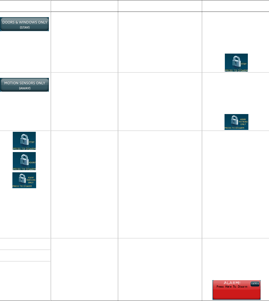
Simon XTi Installation Manual 59
Testing
This section describes how to test the system.
Before testing the system by generating alarms, contact the central station.
Test the system by pressing the icons as described in Table 24. Table 25
provides a list of the arming levels.
Note: An access code is required when arming if the secure arming option is on.
Table 24: System test sequence
Icon
Function tested
Test
Correct result
The panel arms door
and window sensors.
Press the DOORS &
WINDOWS ONLY (STAY)
icon.
Door and window
sensors will be armed
and the following icon
will appear on the
home screen:
The panel will arm
motion sensors.
Press the MOTION
SENSORS ONLY (AWAY)
icon.
Motion sensors will be
armed and the
following icon will
appear on the home
screen:
Depending on
the arming state
of the system,
one of the three
icons will appear
on the screen.
The panel will prompt
you to enter an access
code. Enter the
appropriate code.
Press the appropriate
PRESS TO DISARM icon.
The panel will disarm.
Panic
Press the
EMERGENCY icon on
the home screen to
access these icons.
Press the appropriate icon
to activate a police, fire, or
panic emergency alarm.
The panel will sound
an alarm and the
following alarm icon
will appear with the
alarm message:
Police
Fire

60 Simon XTi Installation Manual
Note: Forty icon presses for invalid codes (ten invalid 4-digit codes, for example)
will cause a system access alarm. The alarm locks all touchpads, except key
fobs, for 90 seconds.
Table 25: Arming levels
Armin
g level
Description
Indication
1
Disarm the system.
One beep indicates the system is disarmed. The panel
displays and speaks Disarmed. The Press to Arm icon
appears on the screen (see Table 7 on page 26).
2
Arm doors and windows.
Two beeps verify that door/window sensors are armed. The
panel speaks Doors and Windows On. The Press to Disarm
Stay icon appears (see Table 7 on page 26).
3
Arm motion sensors.
Three beeps verify that motion sensors are armed. The panel
speaks Motions On. The Press to Disarm Away Motions Only
icon appears on the screen (see Table 7 on page 26).
4
Arm doors, windows,
and motion sensors.
Four beeps verify that door/window and motion sensors are
armed. The panel speaks Doors and Windows On, Motion On.
The Press to Disarm Away icon appears on the screen (see
Table 7 on page 26).
Arming errors
If you select an arming option on the Arm screen, and there is an arming
problem, an arming error message will appear at the bottom of the screen,
indicating what the problem is and how to correct it. For example, you might see
a message that indicates that you need to close the front door.
Correct the problem as indicated or press Bypass. You will see the arming
countdown message at the bottom of the screen. You can press Cancel and
enter your code to stop the arming process.
Sensor test
The sensor test is used to check proper sensor operation.
To test the sensors:
1. Place all sensors in their secured (non alarm) state.
2. Access the System Tests screen through the Status & Settings screen by
pressing ENTER next to System Tests.
3. Enter the dealer, installer or master code and press OK.
4. Press SENSOR TEST.
5. All learned in sensors will be displayed on this screen. Press to scroll
through the pages.

Simon XTi Installation Manual 61
Test your sensors by tripping them one at a time. The panel will display the
number of transmissions received from sensors you trip. See Table 23 on
page 58 for specific instructions on how to trip each sensor type.
The panel sounds beeps, and the display identifies the tripped sensor and the
number of RF packets received. Each beep represents one RF packet. Count
the number of beeps and refer to Table 26 below for minimum requirements.
The panel displays Sn (sensor number) Name, and Rounds Detected (#
Packets). Scroll through to make sure all sensors have been tested.
Table 26: Sensor tripping instructions
Sensor
Instructions
Minimum
packets
required
Hardwire contact
Open the hardwire contact.
1
Door/window
Open the secured door or window.
6 of 8
Freeze
Remove the sensor cover. Apply ice in a plastic bag to the
sensor (for 10 to 15 minutes). Do not allow the sensor to
get wet.
6 of 8
Water
Press a wet rag or wet finger over both of the round, gold-
plated terminals on the underside of the sensor.
6 of 8
Carbon
monoxide alarm
Press and hold the Test/Hush button (approximately 5
seconds) until the unit beeps two times, and then release
the button.
6 of 8
Glassbreak
Test with an appropriate glass break sensor tester.
6 of 8
Motion sensor
Avoid the motion sensor field of view for 5 minutes, and
then enter its view.
6 of 8
Rate-of-rise heat
detector
Rub your hands together until warm, and then place one
hand on the detector for 30 seconds.
6 of 8
Shock
Tap the glass twice, away from the sensor. Wait at least 10
seconds before testing again.
6 of 8
Smoke
Press and hold the test button until the system sounds
transmission beeps.
6 of 8
Personal help
button
Press and hold the appropriate help button until the light
blinks and the panel sounds for at least seven beeps.
6 of 8

62 Simon XTi Installation Manual
Sensor
Instructions
Minimum
packets
required
Key fob
Press and hold the Lock and Unlock buttons
simultaneously for 3 seconds.
6 of 8
Simon XT talking
touch screen
For sensor testing a 1.0. touch screen, press and hold the
Emergency icon for 5 seconds.
For sensor testing a 1.1 or greater touch screen, press the
Settings (gear) icon, scroll down, and then press the RF
Test icon.
6 of 8
Remote
touchpad
Press and hold the two Emergency buttons simultaneously
for 3 seconds.
6 of 8
6. Press Close repeatedly to exit.
Sensor Test Failure
If sirens do not beep when a sensor is tripped, use an RF Sniffer (60-401) test
tool to verify that the sensor is transmitting. Constant beeps from the RF Sniffer
indicate a faulty sensor. Replace the sensor.
If possible, locate sensors within 100 ft. (30 m) of the panel. While a sensor may
have a range of 500 ft. (152 m) or more out in the open, the environment at the
installation site can have a significant effect on transmitter range. A change in
sensor location may help overcome adverse wireless conditions and can
potentially be accomplished by the following:
• Reposition the sensor
• Relocate the sensor
• If necessary, replace the sensor
To reposition a sensor:
1. Rotate the sensor and test for improved sensor communications at 90 and
180 degrees from original position.
2. If poor communication persists, relocate the sensor.
To relocate a sensor:
1. Test the sensor a few inches from the original position.
2. Increase the distance from the original position and retest until an acceptable
location is found.
3. Mount the sensor in the new location.
4. If no location is acceptable, replace the sensor.
To replace a sensor:
1. Test a known good sensor at the same location.
Simon XTi Installation Manual 63
2. If the transmission beeps remain below the minimum level, avoid mounting a
sensor at that location.
3. If the known good sensor functions, contact UTC Fire & Security for repair or
replacement of the problem sensor.
Sensor Testing Notes:
• Conduct sensor test in all possible environmental conditions (For example:
interior doors open and closed, HVAC system on and off, wireless music
system turned on and off).
• Conduct sensor test whenever changes are made to the installation
environment that may impact RF performance (For example: mirrors installed,
metal backed wallpaper, addition of other RF equipment).
• Sensor testing should be done before and after permanent mounting.
Comm Testing
If Comm Test is not finished it will continue to run even if you exit program mode.
Note: Complete panel programming before performing comm testing.
To perform a comm test:
1. Enter the Status & Settings menu.
2. Scroll until System Tests is listed, Press Enter.
3. Enter the dealer, installer or master code and press OK.
4. Press Comm Test.
The panel displays if the comm test was successful or not.
Central station communication
After performing sensor tests, check that the system is reporting alarms
successfully to the central station.
To verify alarm reporting:
Note: The communication with the central station test must be done while NOT in
programming mode.
1. Call the central station and tell the operator that you will be testing the
system.
2. Arm the system.
3. Test an emergency panic icon and trip at least one sensor of each type (fire,
intrusion, etc.) to verify that the appropriate alarms are working correctly.
There is a 30 second delay.
4. When you finish testing the system, call the central station to verify that the
alarms were received.

64 Simon XTi Installation Manual
System download
The system download is used to connect the system with the Enterprise
Downloader software and complete any tasks programmed into Enterprise
Downloader.
To initiate a system download:
1. Access the System Tests screen through the Status & Settings screen by
pressing ENTER next to System Tests.
2. Enter the access code and press OK.
3. Press System Download.
The system will signal when the download is complete.
Offsite phone operation
Test the system from a remote phone by calling the panel and using the
commands in Table 27 below.
When the panel answers the phone call:
1. Press * on the phone.
2. Enter master access or user code.
Table 27: Phone commands
System function
Phone command
Disarm
1
Arm doors/windows
2
Arm motion sensors
3
Arm doors/windows with no entry delay
2 2
Arm doors/windows and motion
sensors
2 3
Listen in to house
5 to listen in to the house
Once in listen in to house the following options are
available:
• 0 or 1 to speak
• 3 or 6 to listen
• 7 to extend call
Note: When in this mode, the user cannot re-enter the
previous menu. You must hang up and call back in to
the panel to perform additional functions.
Specific light on
*, <unit number>
Specific light off
#, <unit number>

Simon XTi Installation Manual 65
System function
Phone command
All lights on
* *
All lights off
# #
System status
0
Audio verification
5 plus X (X= a command from Audio Verification Set)
Terminate session
9
Two-way voice operation
For the central station operator to initiate an audio session:
1. After the panel has completed reporting the alarm, pick up the CS phone and
press the * button to start the audio session.
2. Press 1 or 0 to speak, 2 for VOX operation, and 3 or 6 to listen.
3. Press 99 to terminate the session.
Note: Panel voice announcements are silenced during AVM sessions. If the
operator does not terminate the session correctly, panel announcements may not
occur for up to 90 seconds after the operator hangs up.
Table 28: Audio verification set
Phone button
Function
0 or 1
Speak
2
VOX operation
3 or 6
Listen
7
Extend session for 90 more seconds
88
Terminates session with call back (the panel answers on the first ring if called
within 5 minutes)
99
Terminates session with no call back
Voice event notification
Testing this feature requires two people; one at the alarm site and the other at
the location the panel is programmed to call.
To test voice event notification:
1. Contact the central monitoring station (if the system is monitored) to inform
them you are testing the system and not to dispatch authorities.
2. At the system site, put the system into an alarm condition.
66 Simon XTi Installation Manual
3. At the calling location, pick up the phone after it starts ringing. You should
hear the panel voice announce Press Star for Alarm.
4. Press * and the panel voice identifies the alarm. If there is more than one
alarm in progress, you must press * for the panel voice to identify them.
After all alarms have been identified, the panel announces Press # to Exit.
5. Press # to terminate the call.
You must terminate the call by pressing #. Otherwise, the panel may not
disconnect from the phone line for up to 2 minutes.
Cleaning the touch screen
If necessary, use a soft lint-free cloth to clear smudges on the touch screen; do
not use glass cleaner on the touch screen.
Disposal
Dispose of all equipment is accordance with local requirements.
Simon XTi Installation Manual 67
Troubleshooting
This section provides information to help you diagnose and solve various
problems that may arise while configuring or using your Simon XTi.
System status
To clear Status (alarm memory), from a disarmed state press CLEAR from the
Status & Settings screen.
If the panel displays and announces Siren 1 Failure:
• Turn the hardwired siren supervision option off if a hardwired siren or sensor
is not connected.
• Check for the correct end-of-line resistor in the HW1 I/O circuit.
If the panel displays and announces Low Battery:
• Check that the panel backup battery is connected.
• Check the panel backup battery voltage. If less than 5.4 volts, replace the
battery and clear the system status message.
• Run a sensor test.
If the panel displays and announces RF Jam, the control panel has detected RF
interference.
If the panel displays and announces that a sensor is open, see “Sensors” on
page 43.
If the display shows Set Time and announces System Time is Not Set, set the
system time.
Control panel
If the panel displays and announces Invalid, the sensor is already programmed.
Delete the sensor if not programmed correctly.
If the panel does not beep, turn on the piezo beeps option.
If your screen is not displaying properly, you may need to conduct a screen
refresh. Remove the trim ring (B in Figure 3 on page 14) and depress the reset
key (D in Figure 3 on page 14) on the left side of the XTi. Re-install the trim ring.
Sensors
If a sensor does not work:
• Make sure the battery is good and installed correctly.
• Check for interference from metal objects. Move or rotate the sensor.
• Move the sensor to a new location.
If a door or window is closed, but the panel announces it is open:

68 Simon XTi Installation Manual
• Be certain the arrow on the magnet and the guide line on the transmitter are
aligned and within ¼ inch of each other.
• The sensor tamper switch may be open (cover off).
If a motion sensor goes off continuously, be sure the sensor is mounted on a
solid surface and the viewing field is free from sources of changing temperature.
If a motion sensor does not respond to motion:
• Make sure the sensor battery is good and installed correctly. Wait 2 minutes
after installing a new battery to test the sensor.
• Adjust the sensor mounting.
• Leave the area for 3 minutes, then retest.
• The environment may be too hot or too cold. Outdoor sensors operate
between 32 and 120ºF (0 and 49ºC).
• Dirt or dust may be causing the problem. Wipe the sensor with a clean, damp
cloth.
Specifications
Power
9 VAC, 60 Hz, 25 VA transformer minimum
Rechargeable battery: 6.0 VDC, 2.1 Ah NIMH. Maximum battery
charging current is 120 mA.
Once the battery reaches a low battery condition, a trouble signal will be
annunciated, indicating that the battery may no longer support a full
alarm load.
When fully charged, the battery will operate the panel without AC power
for 24 hours with the panel in a normal, standby condition, followed by 5
minutes in full alarm condition (including the maximum specified
auxiliary load of 250 mA).
Radio frequency
319.5 MHz
Storage temperature
-29 to 140ºF (-34 to 60ºC) without battery
14 to 86ºF (-10 to 30ºC) with battery one year shelf life
Operating temperature
32 to 120ºF (0 to 49ºC)
Maximum humidity
85% relative humidity, noncondensing
Auxiliary power
Unregulated 4.0 to 12.3 VDC, with a maximum of 250 mA

Simon XTi Installation Manual 69
Sensor names
The following tables provide alphabetical and numerically sequential lists of the
sensor name segments.
Table 29: Alphabetical list of sensor name segments
190
1st
192
2nd
193
3rd
194
4th
171
Alarm
175
Alert
039
Attic
137
Baby
186
Back
004
Back door
005
Back window
030
Basement
031
Basement window
144
Bathroom
010
Bedroom
011
Bedroom window
140
Boy’s
161
Carbon monoxide
014
Child’s room
015
Child’s room window
038
Closet
160
Delay door
026
Den
027
Den window
168
Detector
129
Dining room
136
Door
034
Downstairs
035
Downstairs window
148
Driveway
183
East
172
Emergency
158
Entry
130
Family room
142
Fire
189
First
196
First floor
195
Floor
166
Freeze sensor
185
Front
002
Front door
003
Front window
028
Garage
006
Garage door
007
Garage window
141
Girl’s
164
Glass break
012
Guest room
013
Guest room window
155
Gun
156
Hall
036
Hallway
157
Inside
000
Keychain
159
Keyfob
019
Kitchen
020
Kitchen window
131
Laundry
152
Library
017
Living room
018
Living room window
179
Main
180
Master
008
Master bedroom
009
Master bedroom window
167
Medical
037
Medicine cabinet
041
Module
174
Motion
162
Motion detector
150
Mud room
181
North
151
Nursery
024
Office
025
Office window
147
Outside
173
Panic
133
Patio
023
Patio door
146
Pendant
042
Phone module
176
Police
134
Pool
021
Porch
022
Porch window
187
Rear
139
Room
191
Second
197
Second floor
170
Sensor

70 Simon XTi Installation Manual
153
Shed
149
Shop
188
Side
145
Side door
177
Silent police
132
Sliding door
169
Smoke
163
Smoke detector
182
South
029
Special chime
143
Sun room
040
System panic
198
Third floor
001
Touchpad
138
Toy room
178
Transmitter
032
Upstairs
033
Upstairs window
016
Utility room
165
Water sensor
184
West
135
Window
154
Yard
Table 30: Sensor name segments by index number
000
Keychain
001
Touchpad
002
Front door
003
Front window
004
Back door
005
Back window
006
Garage door
007
Garage window
008
Master bedroom
009
Master bedroom window
010
Bedroom
011
Bedroom window
012
Guest room
013
Guest room window
014
Child’s room
015
Child’s room window
016
Utility room
017
Living room
018
Living room window
019
Kitchen
020
Kitchen window
021
Porch
022
Porch window
023
Patio door
024
Office
025
Office window
026
Den
027
Den window
028
Garage
029
Special chime
030
Basement
031
Basement window
032
Upstairs
033
Upstairs window
034
Downstairs
035
Downstairs window
036
Hallway
037
Medicine cabinet
038
Closet
039
Attic
040
System panic
041
Module
042
Phone module
043
A
044
B
045
C
046
D
047
E
048
F
049
G
050
H
051
I
052
J
053
K
054
L
055
M
056
N
057
O
058
P
059
Q
060
R
061
S
062
T
063
U
064
V
065
W
066
X
067
Y
068
Z
069
0
070
1
071
2
072
3
073
4
074
5

Simon XTi Installation Manual 71
075
6
076
7
077
8
078
9
079
/
080
\
081
!
082
@
083
#
084
$
085
%
086
&
087
*
088
(
089
)
090
“
091
-
092
_
093
+
094
=
095
{
096
}
097
|
098
.
099
<
100
>
101
?
102
(space)
103
a
104
b
105
c
106
d
107
e
108
f
109
g
110
h
111
i
112
j
113
k
114
l
115
m
116
n
117
o
118
p
119
q
120
r
121
s
122
t
123
u
124
v
125
w
126
x
127
y
128
z
129
Dining room
130
Family room
131
Laundry
132
Sliding door
133
Patio
134
Pool
135
Window
136
Door
137
Baby
138
Toy room
139
Room
140
Boy’s
141
Girl’s
142
Fire
143
Sun room
144
Bathroom
145
Side door
146
Pendant
147
Outside
148
Driveway
149
Shop
150
Mud room
151
Nursery
152
Library
153
Shed
154
Yard
155
Gun
156
Hall
157
Inside
158
Entry
159
Keyfob
160
Delay door
161
Carbon monoxide
162
Motion detector
163
Smoke detector
164
Glass break
165
Water sensor
166
Freeze sensor
167
Medical
168
Detector
169
Smoke
170
Sensor
171
Alarm
172
Emergency
173
Panic
174
Motion
175
Alert
176
Police
177
Silent police
178
Transmitter
179
Main

72 Simon XTi Installation Manual
180
Master
181
North
182
South
183
East
184
West
185
Front
186
Back
187
Rear
188
Side
189
First
190
1st
191
Second
192
2nd
193
3rd
194
4th
195
Floor
196
First floor
197
Second floor
198
Third floor

Simon XTi Installation Manual 73
Simon XTi system quick reference
Task
Instructions
Level 1: Disarm the system
Control panel: Press Disarm and enter your access code.
Key fob: Press Unlock.
Telephone: Press 1.
Level 2: Arm doors and
windows
Control panel: Press to Arm, Press Doors & Windows Only and
enter your access code (if required).
Key fob: Press Lock.
Telephone: Press 2.
Level 3: Arm motion
sensors
Control panel: Press to Arm, Press Motions Sensors Only and enter
your access code (if required).
Telephone: Press 3.
Level 4: Arm doors,
windows, and motions
Control Panel: Press to Arm, Press Arm All, enter your access code
(if required).
Key fob: Press Lock twice.
Telephone: Press 2 3.
Activate no delay
Control panel: Press to Arm, Press Off next to Entry delay.
Key fob: Press Lock.
Telephone: Press 2 3.
Activate panic alarm
Control panel: Press Emergency, Press Panic, Police, or Fire.
Key fob: Press and hold Lock and Unlock for 3 seconds.
Check system status
Control panel: From the Status & Settings screen, press Listen next
to Panel Status.
Telephone: Press 0.
Chime on or off
Control panel: From the Status & Settings screen, press On or Off
next to Chime.
Specific light on or off
Control panel: From the Status & Settings screen, press Control
next to Lights. From the Lights screen, press on/off next to
designated light.
Key fob: Press *
Telephone: Press * <unit num>
All lights on or off
Control panel: From the Status & Settings screen, press Control
next to Lights. From the Lights screen, press All On/All Off.
Key fob: Press Lights On.
Telephone: Press * twice.
Bypass a sensor
Control panel: From the Status & Settings screen, press Select next
to Direct Bypass, enter Access Code, press Bypass next to
designated sensor.
74 Simon XTi Installation Manual
