351C ITI 351 Install & Reference Manual 1998
2015-08-27
: InterLogix Iti 351 Install & Reference Manual 1998 ITI 351_Install & Reference Manual_1998 library
Open the PDF directly: View PDF ![]() .
.
Page Count: 141 [warning: Documents this large are best viewed by clicking the View PDF Link!]

351 Installation and
Reference Manual

351 Access Point Manager
Installation and Reference Manual
For reprints, order manual: 466-1000, Revision C
Copyright ITI 1998
All rights reserved
Printed in the U.S.A.
651/777-2690
651/779-4890

Interactive Technologies, Inc. © 1998 351 Installation and Reference Manual
1
Notice
State and local fire/life safety codes prohibit the use of access control devices on emergency
exits without providing an approved alternate method of exiting the controlled area.
Emergency exits must be capable of operation by people who are physically handicapped
and by those who have no knowledge of the system. The approval of an alternative exit
method should always be obtained in writing from the appropriate agency involved. In
most cases, this is the state or local fire marshal. The owner should be instructed to obtain
this approval in writing before installing the equipment.
ITI access control systems were not designed to be primary notification devices in a fire or
life safety system. These fire or life safety systems should be monitored and controlled by
devices designed by the manufacturer of those systems. ITI access control systems may be
used as secondary or auxiliary stations, as long as they do not interfere with the operation of
the primary device.
ITI makes no representations or warrantees with respect to the contents hereof and
specifically disclaims any implied warranties of merchantability or fitness for any particular
purpose. Further, ITI reserves the right to revise this publication and to make changes from
time to time in the contents hereof without obligation of ITI to notify any person of such
revision or changes.
All rights strictly reserved. No part of this document may be reproduced, copied, adapted,
or transmitted in any form or by any means without written permission from ITI. Copyright
protection claim included all forms and matters of copyrightable material and information
now allowed by statutory or judicial law, including but not limited to, material generated
from the software programs, which are displayed on the screen, such as icons, screens
display looks, etc.
Trademarks:
ITI is a trademark of Interactive Technologies, Inc.

Interactive Technologies, Inc. © 1998 351 Installation and Reference Manual
2
Table of Contents
List of Figures.................................................................................................................7
List of Tables................................................................................................................... 8
List of Command References........................................................................................ 9
List of Examples ........................................................................................................... 10
1. About This Manual ................................................................................................... 11
1.1. Parts of This Manual..............................................................................................................................11
1.2. Manual Conventions...............................................................................................................................13
2. Product Overview..................................................................................................... 14
2.1. Basic Operations.....................................................................................................................................14
2.2. Schedules .................................................................................................................................................15
2.2.1. Holidays..........................................................................................................................................15
2.2.2. TimeSchedules ...............................................................................................................................16
2.2.3. Daylight Savings ............................................................................................................................16
2.3. Doors........................................................................................................................................................17
2.3.1. Entrance/Exit Devices ....................................................................................................................17
2.3.2. Door Strike .....................................................................................................................................17
2.4. Inputs.......................................................................................................................................................17
2.4.1. Normal State...................................................................................................................................18
2.4.2. Supervision.....................................................................................................................................18
2.4.3. Scheduling......................................................................................................................................19
2.4.4. Door Position and Egress ...............................................................................................................19
2.5. Outputs ....................................................................................................................................................19
2.5.1. Operation........................................................................................................................................19
2.5.2. Scheduling......................................................................................................................................19
2.6. Options.....................................................................................................................................................19
2.6.1. Denied Access ................................................................................................................................19
2.6.2. Interlocking ....................................................................................................................................19
2.6.3. Security System Arm / Disarm.......................................................................................................20
2.6.4. Panic...............................................................................................................................................20
2.6.5. Wireless Point Control ...................................................................................................................20
2.6.6. Occupancy Monitoring...................................................................................................................21
2.7. Cardholder Database .............................................................................................................................21
2.7.1. ID Attributes...................................................................................................................................21
2.7.2. Master Learn / DeleteCards............................................................................................................21
2.8. System Status ..........................................................................................................................................21
2.8.1. Event Reporting..............................................................................................................................21
2.8.2. Reader LED Indications .................................................................................................................22
Interactive Technologies, Inc. © 1998 351 Installation and Reference Manual
3
2.9. Miscellaneous ......................................................................................................................................... 23
2.9.1. Password........................................................................................................................................ 23
2.9.2. Site Code........................................................................................................................................ 23
2.9.3. Customizable Magnetic Stripe Format .......................................................................................... 23
2.10. Power Supply........................................................................................................................................ 23
2.10.1. Power Input.................................................................................................................................. 23
2.10.2. Power Output............................................................................................................................... 23
3. Installation Planning.................................................................................................24
3.1. Schedules................................................................................................................................................. 24
3.1.1. Holidays......................................................................................................................................... 24
3.1.2. Time Schedules.............................................................................................................................. 25
3.1.3. Daylight Savings Time Changes ................................................................................................... 26
3.2. Hardware................................................................................................................................................ 27
3.2.1. Option Kits..................................................................................................................................... 27
3.2.2. Doors.............................................................................................................................................. 27
3.2.3. Inputs ............................................................................................................................................. 28
3.2.4. Outputs........................................................................................................................................... 29
3.2.5. Options........................................................................................................................................... 29
3.2.6. Readers and Keypads..................................................................................................................... 30
3.2.7. Site Codeand Terminal Baud Rate ................................................................................................ 31
3.2.8. Magnetic Stripe Card Data Format................................................................................................ 31
3.2.9. System Power ................................................................................................................................ 34
3.3. Database.................................................................................................................................................. 34
3.3.1. Cardholders.................................................................................................................................... 34
3.3.2. Master Learn / Delete Cards.......................................................................................................... 35
4. Mounting and Wiring ................................................................................................37
4.1. Equipment List....................................................................................................................................... 37
4.1.1. Power Supply................................................................................................................................. 37
4.1.2. Door Peripherals ............................................................................................................................ 37
4.1.3. Optional Add-On Kits.................................................................................................................... 37
4.1.4. Communications............................................................................................................................ 37
4.2. Mounting the APM and Peripherals.................................................................................................... 38
4.3. Wiring the APM and Peripherals......................................................................................................... 39
4.3.1. WiringGuidelines........................................................................................................................... 39
4.3.2. Stripping Shielded Cable............................................................................................................... 39
4.3.3. Grounding Shielded Cable............................................................................................................. 39
4.4. Wiring the Power Supply and Grounding........................................................................................... 41
4.4.1. Wiring an AC Power Supply ......................................................................................................... 41
4.4.2. Wiring a DC Power Supply ........................................................................................................... 42
4.5. Wiring the Outputs................................................................................................................................ 43
4.6. Wiring the Terminal.............................................................................................................................. 45
4.6.1. Configuring the Terminal .............................................................................................................. 45
4.7. Wiring the Readers and/or Keypads.................................................................................................... 46
4.8. Wiring the Inputs................................................................................................................................... 47
4.9. Applying Power...................................................................................................................................... 47
4.9.1. Prepower Checklist........................................................................................................................ 47
4.9.2. Powering Up.................................................................................................................................. 48
Interactive Technologies, Inc. © 1998 351 Installation and Reference Manual
4
4.10. Wiring the Backup Battery..................................................................................................................48
4.10.1. Testing Communications..............................................................................................................48
5. Introduction to Programming.................................................................................. 50
5.1. Programming Conventions....................................................................................................................50
5.1.1. The Ready> Prompt........................................................................................................................50
5.1.2. Aborting Commands ......................................................................................................................50
5.1.3. Command Responses......................................................................................................................50
5.2. List of APM Commands.........................................................................................................................51
5.3. Command Entry Mode ..........................................................................................................................52
5.3.1. Entering Command Entry Mode: LOGON ....................................................................................52
5.3.2. Obtaining a List of Commands: HELP...........................................................................................53
5.3.3. Exiting Command Entry Mode LOGOFF......................................................................................53
5.4. General Procedure for Entering Commands.......................................................................................53
6. Reports ......................................................................................................................54
6.1. Full Report ..............................................................................................................................................54
6.1.1. Power..............................................................................................................................................56
6.1.2. Inputs..............................................................................................................................................56
6.1.3. Outputs ...........................................................................................................................................56
6.1.4. Lock Status.....................................................................................................................................57
6.1.5. TimeSchedules ...............................................................................................................................57
6.1.6. Holidays..........................................................................................................................................57
6.1.7. Daylight Savings ............................................................................................................................57
6.1.8. Options ...........................................................................................................................................57
6.1.9. Doors ..............................................................................................................................................58
6.1.10. Panic.............................................................................................................................................58
6.1.11. Site Code ......................................................................................................................................58
6.1.12. Reader Type .................................................................................................................................58
6.1.13. Reader Led Type ..........................................................................................................................58
6.1.14. Master Learn Cards ......................................................................................................................58
6.1.15. NUMBER OF IDS IN DBASE ....................................................................................................59
6.1.16. Cardholder Database Percentage Full...........................................................................................59
6.2. Event Reports..........................................................................................................................................59
6.3. Cardholder Reports................................................................................................................................60
6.3.1. Category Reports............................................................................................................................60
6.3.2. Cardholder Attributes.....................................................................................................................61
6.3.3. Badge Reports ................................................................................................................................63
6.3.4. NameReports..................................................................................................................................64
7. Programming Your 351............................................................................................ 65
7.1. Basic Setup Commands..........................................................................................................................65
7.1.1. APM Name: APM ..........................................................................................................................65
7.1.2. Current Date: DATE.......................................................................................................................65
7.1.3. Current Time: TIME.......................................................................................................................66
7.2. Schedule SetupCommands.....................................................................................................................67
7.2.1. Holidays: HOL ...............................................................................................................................67
7.2.2. Time Schedules: TS........................................................................................................................68
7.2.3. Daylight Savings Time Changes: DLS...........................................................................................70
Interactive Technologies, Inc. © 1998 351 Installation and Reference Manual
5
7.3. Hardware Setup Commands..................................................................................................................70
7.3.1. Door Setup DOOR..........................................................................................................................71
7.3.2. Inputs and Outputs: IO ...................................................................................................................72
7.3.3. Options: OPT..................................................................................................................................74
7.3.4. Panic Settings: PANIC ...................................................................................................................77
7.3.5. Card Readers: RDR ........................................................................................................................78
7.4. Miscellaneous Setup Commands...........................................................................................................78
7.4.1. Password: PSW...............................................................................................................................78
7.4.2. Site Code: SC .................................................................................................................................79
7.4.3. Magnetic StripeCard Format: SETMAG........................................................................................79
7.5. Control Commands ................................................................................................................................81
7.5.1. Unlock Readers: REL.....................................................................................................................81
7.5.2. Lock Readers: LOCK.....................................................................................................................82
8. Setting Up and Maintaining the Cardholder Database..........................................83
8.1. Attributes.................................................................................................................................................83
8.1.1. Card Number ..................................................................................................................................83
8.1.2. PIN Number....................................................................................................................................83
8.1.3. Cardholder Name............................................................................................................................83
8.1.4. Time Schedules ..............................................................................................................................83
8.1.5. Category .........................................................................................................................................83
8.1.6. Option Privileges............................................................................................................................83
8.2. Adding Individual Cards or PINs .........................................................................................................84
8.2.1. Adding Cards at the Card Reader...................................................................................................84
8.2.2. Adding a PIN, Card, or a Group of Cards with DBASE ................................................................84
8.3. Adding A Group of Cards......................................................................................................................85
8.4. Modifying a Card or PIN.......................................................................................................................86
8.5. Deleting Individual Cards or PINs........................................................................................................87
8.6. Deleting a Group (Block) of Cards........................................................................................................87
8.7. Master Learn / Delete Cards: LEARN .................................................................................................88
8.7.1. Adding Master Learn / Delete Cards..............................................................................................89
8.7.2. Deleting a Master Learn / Delete Card...........................................................................................90
8.7.3. Adding or Deleting Cards With Master Learn / Delete Cards........................................................90
9. Testing and Troubleshooting...................................................................................91
9.1. Testing Procedures .................................................................................................................................91
9.1.1. Testing Inputs.................................................................................................................................91
9.2. Testing Outputs.......................................................................................................................................92
9.2.1. Testing Readers ..............................................................................................................................93
9.2.2. Testing Keypads.............................................................................................................................94
9.2.3. Testing Backup Power....................................................................................................................95
9.3. Reasons Why Outputs Are Active.........................................................................................................95
9.4. Troubleshooting......................................................................................................................................95
10. Appendix A: Specifications..................................................................................103
11. Appendix B: 351 Installation Planning Form......................................................104
12. Appendix C: 351Schedules Planning Form........................................................108
Interactive Technologies, Inc. © 1998 351 Installation and Reference Manual
6
13. Appendix D: 351 Database Planning Form........................................................ 111
14. Appendix E: APM Error Messages ..................................................................... 114
14.1. APM Command Error Messages......................................................................................................114
14.2. Event Error Message..........................................................................................................................115
14.3. The Net Error Message......................................................................................................................116
14.3.1. Receive-Side Net Errors.............................................................................................................116
14.3.2. Transmit-Side Net Errors ...........................................................................................................117
14.3.3. Operating System Net Errors......................................................................................................117
14.4. When Might Net Errors Appear? .....................................................................................................117
14.4.1. Startup Errors .............................................................................................................................117
14.4.2. Shutdown Errors.........................................................................................................................117
15. Appendix F: Glossary of APM Terms................................................................. 118
Index ............................................................................................................................ 123

Interactive Technologies, Inc. © 1998 351 Installation and Reference Manual
7
List of Figures
Figure 1: How the 351 Handles Access Control......................................................................................................14
Figure 2: How the 351 Handles Alarm Monitoring...............................................................................................15
Figure 3: 351 Input Configurations .........................................................................................................................18
Figure 4: 351 Mounting Dimensions........................................................................................................................38
Figure 5: 351 Wiring Diagram .................................................................................................................................40
Figure 6: Wiring a 16 VAC Power Supply.................................................................................................................42
Figure 7: Wiring a DC Power Supply......................................................................................................................42
Figure 8: Normally Open Strike at Door 1..............................................................................................................44
Figure 9: Magnetic Strike at Door 2 ........................................................................................................................44

Interactive Technologies, Inc. © 1998 351 Installation and Reference Manual
8
List of Tables
Table 1: Reader LEDStates ......................................................................................................................................22
Table 2: SETMAG Command Field Descriptions..................................................................................................32
Table 3: The Output Connections............................................................................................................................43
Table 4: The Terminal Baud Rate DIP Switch Settings.........................................................................................45
Table 5: Terminal Configuration Settings ..............................................................................................................46
Table 6: The Input Connections...............................................................................................................................47

Interactive Technologies, Inc. © 1998 351 Installation and Reference Manual
9
List of Command References
Command Reference 1: APM Command Table .....................................................................................................52
Command Reference 2: LOGON..............................................................................................................................52
Command Reference 3: HELP..................................................................................................................................53
Command Reference 4: LOGOFF ............................................................................................................................53
Command Reference 5: General Procedure for Entering Commands.................................................................53
Command Reference 6: Full Report........................................................................................................................54
Command Reference 7: Event Report.....................................................................................................................59
Command Reference 8: Category Report ...............................................................................................................60
Command Reference 9: Badge Report ....................................................................................................................63
Command Reference 10: Name Report...................................................................................................................64
Command Reference 11: APM .................................................................................................................................65
Command Reference 12: DATE ...............................................................................................................................66
Command Reference 13: TIME ................................................................................................................................66
Command Reference 14: HOL..................................................................................................................................68
Command Reference 15: TS .....................................................................................................................................69
Command Reference 16: DLS ..................................................................................................................................70
Command Reference 17: DOOR...............................................................................................................................71
Command Reference 18: IO......................................................................................................................................73
Command Reference 19: Setting Options for Outputs 2 and 4 .............................................................................77
Command Reference 20: PANIC..............................................................................................................................77
Command Reference 21: RDR..................................................................................................................................78
Command Reference 22: PSW..................................................................................................................................79
Command Reference 23: SC.....................................................................................................................................79
Command Reference 24: SETMAG..........................................................................................................................80
Command Reference 25: REL ..................................................................................................................................81
Command Reference 26: LOCK...............................................................................................................................82
Command Reference 27: Adding an Individual Card or PIN with DBASE.........................................................85
Command Reference 28: Adding a Group of Cards with DBASE........................................................................86
Command Reference 29: Modifying Cards or PINs with DBASE ........................................................................87
Command Reference 30: Deleting Individual Cards or PINs with DBASE.........................................................87
Command Reference 31: Deleting Groups of Cards with DBASE........................................................................88
Command Reference 32: Adding Master Learn / Delete Cards with LEARN.....................................................89
Command Reference 33: Deleting Master Learn / Delete Cards with LEARN ...................................................90

Interactive Technologies, Inc. © 1998 351 Installation and Reference Manual
10
List of Examples
Example 1: Planning APM Holiday Intervals.........................................................................................................25
Example 2: Planning APM Time Schedules............................................................................................................26
Example 3: Planning APM Time Changes..............................................................................................................27
Example 4: Planning APM Add-On Options..........................................................................................................27
Example 5: Planning APM Door Strikes.................................................................................................................28
Example 6: Planning APM Inputs ...........................................................................................................................29
Example 7: Planning APM Outputs ........................................................................................................................29
Example 8: Planning APM Options.........................................................................................................................30
Example 9: Planning APM Card Readers and Keypads .......................................................................................31
Example 10: Planning APM Site Code and Terminal Baud Rate.........................................................................31
Example 11: Planning your APM Magnetic Stripe Card Data Format ...............................................................33
Example 12: Planning the System Power................................................................................................................34
Example 13: Planning the Cardholder Database ...................................................................................................35
Example 14: Planning Master Learn / Delete Cards..............................................................................................36
Example 15: The Full APM Report.........................................................................................................................56
Example 16: An Event Report..................................................................................................................................60
Example 17: The Category Report (for All Categories) ........................................................................................61
Example 18: The Category Report (for One Category).........................................................................................61
Example 19: Category Report for a Single Category.............................................................................................62
Example 20: Category Report With No Listing......................................................................................................62
Example 21: Badge Report for a Card....................................................................................................................63
Example 22: Badge Report for a PINBadge Report for a Card............................................................................63
Example 23: Name Report........................................................................................................................................64
Example 24: Setting Magnetic Stripe Card Data Format......................................................................................80

Interactive Technologies, Inc. © 1998 351 Installation and Reference Manual
11
1. About This Manual
This section describes the parts of this manual and the text conventions used within it.
1.1. Parts of This Manual
The 351 Installation and Reference Manual is for installers and users. It contains detailed
information about how to install your APM and how to enter and maintain optional settings.
The 351 Installation and Reference Manual contains the following sections:
Section 1: About This Manual
This section describes how your APM works, provides an overview of the installation process,
and explains how to use this manual.
Section 2: Product Overview
This section is a general introduction that describes how to use your APM. General terminology
and concepts specific to your APM are explained here.
Section 3: Installation Planning
This section describes how to plan and document an installation, for both your APM and
peripherals.
Section 4: Mounting and Wiring
This section describes how to mount and wire your APM and peripherals.
Section 5: Introduction to Programming
This section describes a basic introduction to programming the APM and lists the commands
supported by your APM.
Section 6: Reports
This section describes how to run several reports on your APM.
Section 7: Programming
This section provides instruction on using many APM commands.
Section 8: Setting-Up and Maintaining the Cardholder Database
This section provides instruction on setting-up and maintaining your cardholder database.
Section 9: Testing and Troubleshooting
This section lists testing procedures, as well as describes possible problems and solutions.
Appendix A: Specifications
Interactive Technologies, Inc. © 1998 351 Installation and Reference Manual
12
This appendix provides a list of the specifications for the APM.
Appendix B: The 351 Installation Planning Form
This appendix contains a master copy of the 351 Installation Planning Form, which is essential in
setting up your APM.
Appendix C: The 351 Schedules Planning Form
This appendix contains a master copy of the 351 Schedules Planning Form, which is essential in
setting up your APM.
Appendix D: The 351 Database Planning Form
This appendix contains a master copy of the 351 Database Planning Form, which is essential in
setting up your APM.
Appendix E: Error Messages
This appendix contains command and event error messages for the APM.
Appendix F: Glossary
This appendix contains terms and definitions used in the 351 Installation and Reference Manual.

Interactive Technologies, Inc. © 1998 351 Installation and Reference Manual
13
1.2. Manual Conventions
This section defines graphical and typographical conventions used in this manual.
Below are the graphical conventions used in this manual:
❖A diamond in the left margin indicates steps for accomplishing a
task.
CAUTION! Text in a box preceded by the word CAUTION indicates that you
should read the information carefully or grave consequences may
result.
Below are the textual cues used within this manual:
APM OK This text indicates information displayed on your terminal.
ABC This text indicates exact text you should type, such as commands.
It appears in boldface.
APM_NAME This text indicates information you provide, such as names and
numbers. It appears in boldface and italics.
[Esc] [Rtn] This text indicates keys you should press. It appears in boldface
and brackets.
When the following terms are used in this manual, the intended meanings are listed below:
APM “APM” refers to the ITI Access Point is used interchangeably with
the term “351 APM is a card access, alarm point monitoring, and
device control processor for buildings, rooms, parking lots, etc.
Terminal “Terminal” refers to any device, linked to your APM via an RS-
232 communications interface, that is used to program or display
data from the APM. The terminal most often used for
programming your APM is a CRT and keyboard. The terminal
used for displaying APM data can be a CRT or a printer device.
Interactive Technologies, Inc. © 1998 351 Installation and Reference Manual
14
2. Product Overview
This section is a general introduction, which describes how to use your APM to control access and
monitor alarms. General terminology and concepts are introduced and explained below.
2.1. Basic Operations
The 351 Installation and Reference Manual is for installers and users. It contains detailed
information about how to install your APM and how to enter and maintain optional settings.
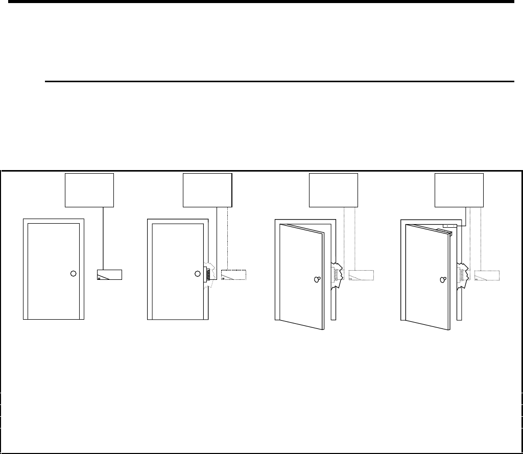
1251G24A.DS4
351 351 351 351
1. A person slides a card 2. If the card has access to 3. The person opens 4. A sensor on the
through a reader, which the door at the current time, the door and enters. door verifies that
is mounted near the door your APM sends a signal to the door has closed
and wired to the 351 APM. the electronic lock (door or sends an alarm
strike) to unlock the door. to the APM.
Figure 1: How the 351 Handles Access Control
Interactive Technologies, Inc. © 1998 351 Installation and Reference Manual
15
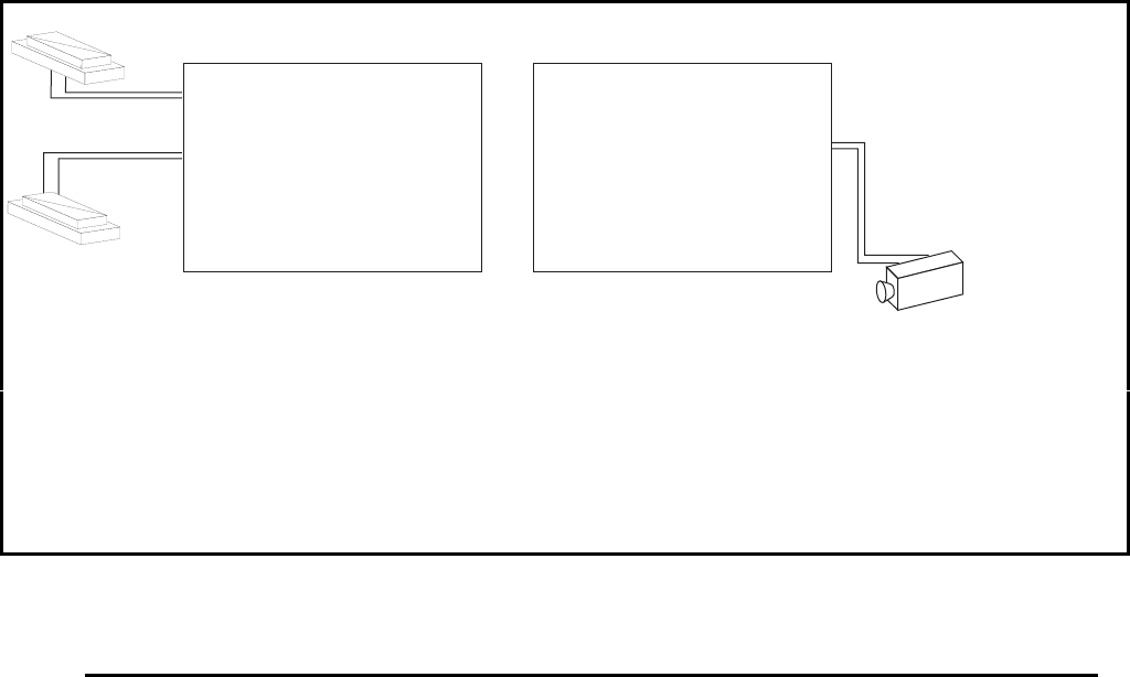
Camera
DOOR
POSITION
SENSOR
DOOR
POSITION
SENSOR
9148G03A.DS4
351 351
1. The door position sensors are wired to the 351 2. The 351 responds to the open door event,
APM’s incoming connections (inputs). as programmed. It sends an alarm message to
An input tells the 351 when a sensor is in the the terminal and may also send a signal to one
alarm state. of its relays (outputs), which is wired to a
device such as an alarm, light, or closed circuit
camera.
Figure 2: How the 351 Handles Alarm Monitoring
2.2. Schedules
Access control is accomplished by evaluating two main criteria:
• the presentation of a token (a card or PIN) for access, and
• the date and time of the access attempt.
Schedules provide the means for controlling the date and time considerations of access control.
2.2.1. Holidays
A holiday is a date/time interval. During a holiday, normal time schedules are overridden by the
holiday schedule. That is, the normal time schedule is not used during a holiday, the holiday
schedule is used instead. Holiday schedules can restrict or prevent access, depending on how you
program them. Up to 10 holidays can be defined and each holiday can consist of one or more
days.
For example, you could program a time schedule to allow cardholders access from 8 AM to 5 PM,
Monday through Friday, but not holidays. Then, if a holiday occurs on a weekday, normal
cardholder access is not allowed. However, once the holiday is over, normal cardholder access
will resume.
Interactive Technologies, Inc. © 1998 351 Installation and Reference Manual
16
The APM uses two types of holidays:
• Fixed— the holiday occurs on the same day(s) every year, such as New Year's.
• Variable— the holiday occurs on different day(s) each year, such as Memorial Day.
2.2.2. Time Schedules
A time schedule is a combination of a time interval and one or more days of the week. Holidays
are a special type of day of the week.
Time schedules are used when assigning access times to tokens in the database, selecting when to
ignore (or shunt) message from alarms, or specifying when an output device is normally on.
For example, one time schedule could consist of the hours from 8 AM to 5 PM Monday through
Friday. Another time schedule could be set up for the hours from 8 AM to 5 PM Monday through
Friday, plus Saturday, Sunday, and holidays. The first time schedule might be used to allow
access for general office personnel. The second schedule could be used for supervisors.
To ignore alarm messages from a motion sensor during the regular office hours, the sensor could
be assigned the first time schedule. The motion sensor alarms would not be recorded during the
hours from 8 AM to 5 PM Monday through Friday.
If the lights are controlled by your APM and assigned the first time schedule, then they will be on
automatically from 8 AM to 5 PM Monday through Friday.
Up to 4 access schedules can be defined. There are also two special time schedules:
• always and
• never.
2.2.3. Daylight Savings
Since an access control system is very dependent on the current time and date, time changes, like
Daylight Savings Time, could be a problem. Therefore, twice each year your APM automatically
adjusts the current time to a time you specify.

Interactive Technologies, Inc. © 1998 351 Installation and Reference Manual
17
2.3. Doors
2.3.1. Entrance/Exit Devices
Entrances or exits from the door can be controlled with card readers and/or keypads. Further,
exiting can also be controlled by a switch.
Card readers are used to pass along information encoded on a card. There are several types of card
readers:
• Wiegand
• Proximity
• Bar code
• Magnetic stripe
The RF Access Receiver is a special device that is used like a standard Wiegand card of cards. In
addition to the ID and site code, the wireless receiver sends keypress information. Sending this
information enables the APM to perform special functions like door selection, panic, and wireless
point control.
Keypads are used to enter Personal Identification Numbers (PINs), which can be used alone or
along with cards.
An egress (exit) input can be used for a simple way of unlocking the door for exit. The input can
be a button, motion detector, or crash bar.
2.3.2. Door Strike
The door strike is a device that locks or unlocks the door. It is controlled by the APM, which is set
up by the user.
There are three strike types supported by the APM:
• Memory— The door locks when it opens. This is typically used with spring-bolt type
locks
• Non-Memory— The door locks when it closes. This is typically used with magnetic or
dead-bolt type locks
• Fixed Time— The door locks at the end of the strike time. This can be used on spring-
bolt, dead-bolt, and magnetic types of locks.
The strike time is the length of time that the door is unlocked during access.
The ajar time is the length of time after the strike time has expired, but before a door-open
message is sent.
Interactive Technologies, Inc. © 1998 351 Installation and Reference Manual
18
2.4. Inputs
Inputs are essentially switches monitored by the APM. There are four general-purpose inputs, plus
a tamper input.
2.4.1. Normal State
Inputs can be set up as either normally open (NO) or normally closed (NC):
• Normally Open— The input is considered to be in the alarm state when it becomes a
short circuit.
• Normally Closed— The input is considered to be in the alarm state when it becomes an
open circuit.
2.4.2. Supervision
Inputs can be supervised or unsupervised:
• Unsupervised— The input has only two states: electrically a short circuit (closed) or
electrically an open circuit (open).
• Supervised— The input is wired with a fixed resistor to detect tampering, which allows
the input to have three states : open, closed, or resistive.
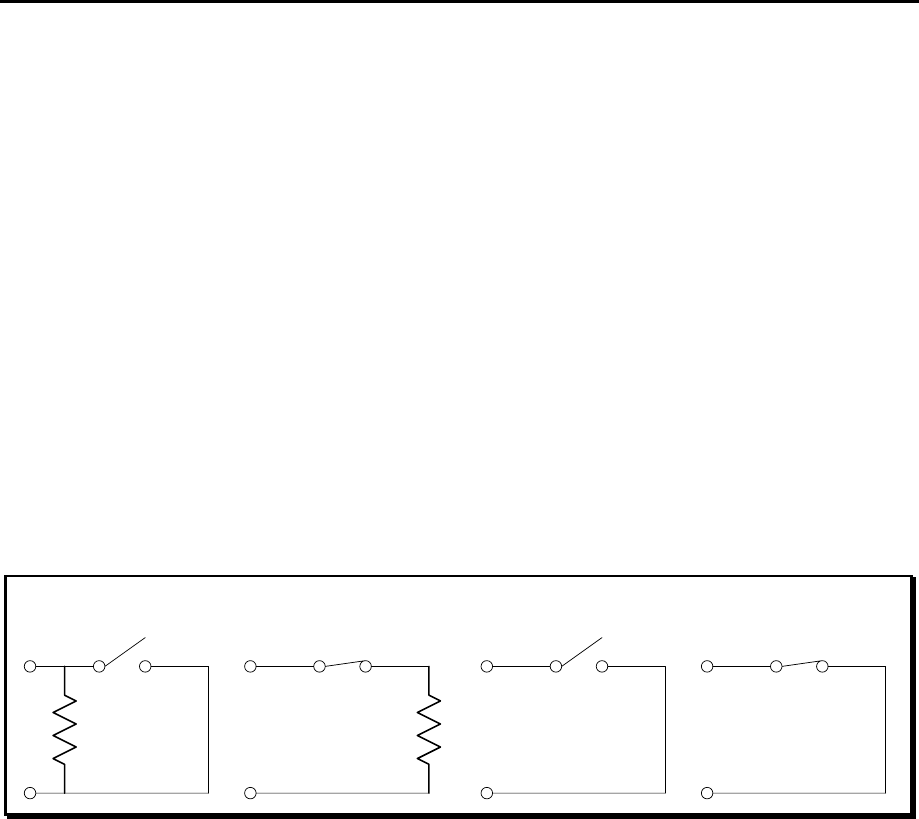
Figure 3: 351 Input Configurations
Supervised inputs are considered to be in the “normal state” when the input is resistive. The
alarm state is a short (is closed) for a normally open connection or is open for a normally closed
connection. A trouble state is open for a normally open connection or a short (is closed) for a
normally closed connection.
Supervised
Normally Open Supervised
Normally Closed
Non-Supervised
Normally Open
Non-Supervised
Normally Closed

Interactive Technologies, Inc. © 1998 351 Installation and Reference Manual
19
2.4.3. Scheduling
Inputs are assigned a time schedule, which is when input state changes will not be reported. Inputs
are assumed to be in the normal state when the time schedule is active.
2.4.4. Door Position and Egress
The APM's four inputs are generally used as door position (open or closed) and egress (exit
request) for each of the two doors. However, you can alter this setup for custom installations.
2.5. Outputs
Outputs are essentially switches controlled by the APM. There are two outputs used for the door
strike and two general-purpose outputs. All four outputs are form-C type voltage-free relays, rated
at 3 Amps, 24 VAC or 30 VDC.
2.5.1. Operation
Each output is in either an active or inactive state:
• Inactive— Results when there is a closed circuit between the normally closed and
common terminals.
• Active— Results when there is a closed circuit between the normally open and common
terminals when the relay switches.
The output device is typically connected to power at the normally open and common points,
through the associated relay. Normally, the device is off. However, when the output is activated,
the device turns on.
It is possible to connect output devices that behave in the reverse fashion. That is, a can be
connected so that it is normally on and is turned off when the output is activated.
2.5.2. Scheduling
Outputs can be assigned a time schedule, which is when a relay will be active.
2.6. Options
“Options” are conditions that can be set up for controlling the operation of the two general-
purpose outputs. Several types of options are defined in this section.
2.6.1. Denied Access
The Denied Access Option pulses (turns on) for 10 seconds whenever an invalid access attempt
occurs. This option is associated with a specific door and reader.
2.6.2. Interlocking
The Interlocking Option turns on an output when one or more interlocked (mapped) inputs are in
the alarm state.
Interactive Technologies, Inc. © 1998 351 Installation and Reference Manual
20
2.6.3. Security System Arm / Disarm
The Arm / Disarm Option is designed to be an interactive control for arming and disarming a
security system. When the output is inactive, the security system reads an open circuit, which is
interpreted as a request to arm. When the output is active, the security system is presented with a
closed circuit, which is interpreted as a request to disarm.
Since the output state can be assigned a time schedule, your APM can automatically arm a
security system. For example, if a time schedule ends at 5 PM, the alarm system will
automatically arms itself then.
The security system will not automatically disarm when the time schedule begins, say at 9 AM.
Instead, the security system will remain armed, until a card with disarm privileges is swiped at the
door
Tokens, such as the above mentioned card, can have Arm / Disarm privileges. With such a card, a
single swipe at the card reader disarms your system (the output becomes active). Similarly, with a
double swipe of such a card arms your system (the output becomes inactive).
Note: The actual state of the security system must be provided at the tamper input of the APM.
2.6.4. Panic
The Panic Option can only be used with the ITI RF Access Receiver® (ITI P/N 60-663-95). The
receiver sends keypress information with the ID number. The [ARM]+[DISARM] keypress
generates a panic signal from either the 2- or 4-Button Keychain Transmitter. Additionally, a
panic signal can come from pendant panic transmitters.
If the transmitter’s ID number is valid and a panic keypress was sent, an output is activated.
The amount of time, or “duration,” the output is active can be selected by the user. There are two
time settings used to determine this duration:
• An “initial on time a length of time the output must be active.
Note: The initial on time cannot be canceled.
• There is also a “time-out duration,” after which the output is inactive
The output is on for at least as long as the initial on time. After the initial on time, the output can
be deactivated by any valid access attempt. However, if a valid access attempt is not made, the
output turns off when the time-out is reached.
2.6.5. Wireless Point Control
The Wireless Point Control Option can only be used with the RF Access Receiver and 4-Button
Keychain Transmitters. The receiver sends keypress information with the ID number. The
[LIGHTS] and [STAR] keypresses can control the state of an output.
Tokens can be assigned a point control privilege. When a valid token with this privilege is
presented at the reader, with either the [LIGHTS] or [STAR] keypress, the output state is
switched.
The Wireless Point Control Option can turn on an output it controls before its time schedule
begins. When its time schedule expires, the output will automatically turned off. If it is turned on
outside its normal hours, the output should be manually turned off. However, in both situations,
the output returns to its normal time schedule on the next day.

Interactive Technologies, Inc. © 1998 351 Installation and Reference Manual
21
For example, you could wire your neon open sign as a Wireless Point Control Option. The sign’s
time schedule could automatically turn it on at 9 AM and off again at 6 PM. However, you could
turn the sign on earlier, say at 8:30 AM, or keep it on later, say until 7 PM, and manually turn it
off before you leave. In both examples, the sign would resume its normal time schedule for the
next business day.
2.6.6. Occupancy Monitoring
The Occupancy Monitoring Option turns on an output when a maximum occupancy is reached. In
addition to this, card readers can be disabled when the maximum occupancy is reached. This
option is associated with a specific door and reader.
2.7. Cardholder Database
The database stores the ID numbers of each cardholder. The ID can be a card, a PIN, or both. The
APM can store up to 250 IDs.
2.7.1. ID Attributes
Each ID is associated with specified attributes, which are listed below:
• Name of cardholder
• Time schedule for each door (which can be different)
• Category, for reporting purposes
• Security system Arm / Disarm privilege
• Wireless Point Control privilege
2.7.2. Master Learn / Delete Cards
Five special cards can be set up to add or remove cards to or from your APM database at the card
reader.
Four of the cards can be used to add cards to the database. Each of these Master Learn Cards is
assigned attributes that are transferred to new cards added to your system. When a Master Learn
Card slides through or is presented to the reader, the next card that is presented will be assigned
the Master Card’s attributes and be added to your APM database.
The fifth Master Card, a Master Delete Card, is used to delete cards from your APM database.
When the Master Delete Card is presented to the reader, the next card that is presented will be
removed from your APM database.
Note: Swiping a Master Learn / Delete Card through a card reader will not provide access
through a door.
2.8. System Status
2.8.1. Event Reporting
“Events” are conditions that your APM can detect, such as access attempts, whether valid or
invalid, and changes of the state of an input.

Interactive Technologies, Inc. © 1998 351 Installation and Reference Manual
22
All events that occur are reported at the terminal and stored in the event log. Up to 250 events will
be stored in the event log, which can be displayed or printed.
2.8.2. Reader LED Indications
Each reader LED (light-emitting diode) responds to access attempts with a valid access or invalid
access response. If the security system Arm / Disarm Option is selected, the reader LED also
displays the current Arm / Disarm state. When a Master Learn / Delete Card is presented, the
reader LED response shows that the reader is ready to add or delete a card.
The reader LED responds slightly differently for some conditions, depending on whether it is a
red-only or red/green type.
Indicated State Red-Only LED Red/Green LED
Door Secure solid red solid red
Granting Access ½ second ON
½ second OFF
solid green
Denied Access ¼ second ON
¾ second OFF
½ second red
½ second green
Security Armed 0.9 second ON
0.1 second OFF
0.9 second red
0.1 second green
Security Disarmed 0.1 second ON
0.9 second OFF
0.1 second red
0.9 second green
Card Learning very fast blinking very fast blinking
Table 1: Reader LED States

Interactive Technologies, Inc. © 1998 351 Installation and Reference Manual
23
2.9. Miscellaneous
2.9.1. Password
Commands used to set up and control APM operation are password protected. The APM setup can
be altered only after logging on with the correct password.
2.9.2. Site Code
The APM has a site code that can be selected by the users. Every card used at the reader has a site
code, as well as an ID number. Every card's site code must match the APM’s site code.
Note: If the card’s site code match the APM’s site code, no access is given.
2.9.3. Customizable Magnetic Stripe Format
Magnetic stripe cards can have different formats. The format used by your APM to determine the
card number and site code encoded in the magnetic stripe, which can be customized by the user.
2.10. Power Supply
2.10.1. Power Input
The APM can be powered using a 16 VAC or 18-24 VDC power supply. Additionally, a battery
backup kit (ITI P/N 34-006) is available to supply power if primary power fails.
2.10.2. Power Output
The APM can provide a total power of 600 mA at 12 VDC or 5 VDC, for all external devices,
including card readers, keypads, door strikes, and all input and output devices.

Interactive Technologies, Inc. © 1998 351 Installation and Reference Manual
24
3. Installation Planning
Planning an installation should be done before mounting, wiring, and programming your system.
Please copy and complete the 351 Installation Planning, 351 Schedules Planning, and 351
Database Planning forms (found in Appendices B, C, and D).
Use this section to answer questions that may arise during system setup. This will make
programming easier and provide documentation about your system.
Throughout this section, you will see examples that relate to the planning forms. These examples
are intended to guide your installation planning.
3.1. Schedules
Schedules are used for both hardware and database setups.
Note: Your setup is much easier if all schedules are completed first.
3.1.1. Holidays
Holidays are a special type of day that can be used on an access schedule. Whenever possible,
complete the holiday table before the time schedule table.
❖ ❖ How to Select Each Holiday Interval
1. On your planning form, record a description of the holiday.
2. Determine and mark the type of holiday:
• fixed or
• variable.
3. Determine and write down the date and time the holiday will begin.
4. Determine and write down the date and time the holiday will end.

Interactive Technologies, Inc. © 1998 351 Installation and Reference Manual
25
See the table below for an example on planning your APM holidays:
HOLIDAYS
Holiday Description Type
Start
Date
Start
Time End Date End
Time
1 New Year’s ■ Fixed
❑ Variable
12/31
00:00 01/01 23:59
2 Memorial Day ❑ Fixed
■ Variable
05/25/98
00:00 05/25/98 23:59
3 Independence Day ■ Fixed
❑ Variable
07/04
00:00 07/04 23:59
4 Labor Day ❑ Fixed
■ Variable
09/01/97
00:00 09/01/97 23:59
5 Thanksgiving ❑Fixed
■ Variable
11/27/97
00:00 11/28/97 23:59
6 Christmas ■ Fixed
❑ Variable
12/24
00:00 12/25 23:59
7 Memorial Day ❑ Fixed
■ Variable
05/31/99
00:00 05/31/99 23:59
8 Plant Closed ❑ Fixed
■ Variable
08/05/97
08:00 08/07/97 16:59
9❑ Fixed
❑ Variable
__/__/__
__:__ __/__/__ __:__
10 ❑ Fixed
❑ Variable
__/__/__
__:__ __/__/__ __:__
Example 1: Planning APM Holiday Intervals
3.1.2. Time Schedules
Each of the time schedules you define is divided into four time zones. Each time zone consists of
one or two time intervals, as well as the days of the week that these hours will be active. Since
you have four time schedules, you have a total of 16 time zones and a maximum total of 32 time
intervals.
❖ ❖ How to Select Each Time Schedule, Time Zone, and Time Interval
1. Determine and write down the first interval’s start and end time on your planning form.
2. Determine and write down the second interval’s start and end time (if used).
3. Determine and mark the days of the week each interval will be active.

Interactive Technologies, Inc. © 1998 351 Installation and Reference Manual
26
See the table below for an example on planning your APM’s Time Schedules:
TIME SCHEDULES
Schedule Zone Interval 1 Interval 2 Days
Start
Time End
Time Start
Time End
Time
(1)
Mon. (2)
Tues. (3)
Wed. (4)
Thurs. (5)
Fri. (6)
Sat. (7)
Sun. (8)
Hol.
A0 00:00 07:59 __:__ __:__ ■■■■■■■❑
1 08:00 08:29 23:30 23:59 ■■■ ■■■■❑
2 __:__ __:__ __:__ __:__ ❑❑❑ ❑❑❑❑❑
3 __:__ __:__ __:__ __:__ ❑❑❑ ❑❑❑❑❑
B0 08:00 15:59 __:__ __:__ ■■■ ■■■■ ❑
1 07:30 07:59 16:00 16:29 ■■■ ■■■■❑
2 __:__ __:__ __:__ __:__ ❑❑❑ ❑❑❑❑❑
3 __:__ __:__ __:__ __:__ ❑❑❑ ❑❑❑❑❑
C0 16:00 23:59 __:__ __:__ ■■■ ■■■■❑
1 00:00 00:29 15:30 15:59 ■■■ ■■■■❑
2 __:__ __:__ __:__ __:__ ❑❑❑ ❑❑❑❑❑
3 __:__ __:__ __:__ __:__ ❑❑❑ ❑❑❑❑❑
D0 08:00 16:59 __:__ __:__ ■■■ ■■■■■
1 06:30 07:59 17:00 18:29 ■■■ ■■❑❑❑
2 __:__ __:__ __:__ __:__ ❑❑❑ ❑❑❑❑❑
3 __:__ __:__ __:__ __:__ ❑❑❑ ❑❑❑❑❑
X00:00 23:59 (always) ■■■ ■■■■■
Y00:00 00:00 (never) ❑❑❑ ❑❑❑❑❑
Example 2: Planning APM Time Schedules
3.1.3. Daylight Savings Time Changes
Two automatic time changes can be programmed in your APM.
❖ ❖ How to Select Automatic Time Changes
1. On your planning form, record a description of each time change (see Example 3).
2. Determine and write down the dates for the time change to take effect.
3. Decide upon what hour you want the time change to take effect.
Note: Daylight Savings Time changes are traditionally made at 2 AM. However, you can set
your time changes to take effect at any time.
4. Write the above time in the “old time” column on your planning form.
5. Determine and write down the new hours that the time change will assume.
See the table on the next page for an example on an planning your APM’s automatic time
changes:

Interactive Technologies, Inc. © 1998 351 Installation and Reference Manual
27
DAYLIGHT SAVINGS TIME CHANGES
Time Change Description Date
Old Time
New Time
1 Daylight savings time starts. 04/26
02:00
03:00
2 Daylight savings time ends. 10/26
02:00
01:00
Example 3: Planning APM Time Changes
3.2. Hardware
This section outlines planning the hardware used with your system.
3.2.1. Option Kits
Select any add-on option kits used with the APM.
See the table below for an example on planning option kits:
ADD-ON OPTION KITS
❑ Keypad ❑ Battery Backup Kit
Example 4: Planning APM Add-On Options
3.2.2. Doors
Door hardware involves the electromechanical strikes used to lock or unlock the doors.
❖ ❖ How to Plan Each Door Strike
1. On your planning form, record the make, model, and voltage of the strike being used (see
Example 5).
2. Select the appropriate contact type, depending on how the strike is to be connected.
Note: Normally open door strike contacts can also be referred to as “fail-secure.” Power is
applied to the strike to open the door. If power is lost, the relay will remain open, and the
door will remain in its secure state.
Normally closed strike contacts can be referred to as “fail-unsecure.” Power is applied
to the strike when the door is secure. If power is lost, the relay will open and the door
will be unlocked.
3. Select the appropriate type of door strike based on the requirements of the strike for proper
operation.
4. Determine and write down the strike time for the door.
5. Determine and write down the door ajar time.

Interactive Technologies, Inc. © 1998 351 Installation and Reference Manual
28
See the table below for an example on planning your APM’s door strikes:
DOOR STRIKES
Door Make & Model Voltage Contact Type Type Strike
Time Ajar
Time
1 ABC Locks
SpringBolt 12 12 V ❑ Norm. Open
■ Norm. Closed
■ Memory
❑ Non-Memory
❑ Fixed Time
515
2 ABC Locks
MagLock 1000 24 V ■ Norm. Open
❑ Norm. Closed
❑ Memory
■ Non-Memory
❑ Fixed Time
15 30
Example 5: Planning APM Door Strikes
3.2.3. Inputs
Inputs can be a variety of devices that provide a switch open/closed state. This can be a simple
switch, push-button, or a sensor, such as a motion detector.
❖ ❖ How to Plan Each APM Input
1. On your planning form, record a name (10 characters or less) and description for each input
(see Example 6).
2. Using the time schedule table, determine a schedule when alarm messages will be ignored
(shunted).
3. Select the appropriate contact type, depending on how the input device is to be connected to
the APM.
4. Include other setup information and select the appropriate options:
• select interlocked if the input will be interlocked to an output.
• select supervised if the input will be supervised by using an end-of-line resistor.
• select egress if input 2 and / or 4 will be used for opening the door on exit.

Interactive Technologies, Inc. © 1998 351 Installation and Reference Manual
29
See the table below for an example on planning your APM’s inputs:
INPUTS
Input Name and
Description Schedule Contact Type Setup
1 DOOR1_POS
Position Switch Y❑ Norm. Open
■ Norm. Closed
■ Supervised
❑ Interlocked to: ② ④
2 EGRESS_1
Crashbar D■ Norm. Open
❑ Norm. Closed
❑ Supervised
■ Egress (set by default)
■ Interlocked to: ❷ ④
3 DOOR2_POS
Position Switch Y❑ Norm. Open
■ Norm. Closed
❑ Supervised
❑ Interlocked to: ② ④
4 EGRESS_2
Motion Sensor D■ Norm. Open
❑ Norm. Closed
■ Supervised
■ Egress (set by default)
■ Interlocked to: ② ❹
Example 6: Planning APM Inputs
3.2.4. Outputs
Outputs can be a variety of devices that are switched on or off by the APM, including the strikes
used for the doors. The other two outputs are general purpose, and can be used for such devices as
a siren, light, or camera.
❖ ❖ How to Plan Each APM Output
1. On your planning form, record a name (10 characters or less) and description for each output.
2. Using the time schedule table, determine a schedule when the output will be active.
3. Include other setup information that could be beneficial in the notes area of your form.
See the table below for an example on planning your APM’s outputs:
OUTPUTS
Output Name and Description Schedule Notes
1 STRIKE_1
SpringBolt 12 Y Default door 1 strike
2 CCTV_1
Camera outside of Door 1 D Set to show entry from parking
3 STRIKE_2
MagLock 1000 Y Default door 2 strike
4 CCTV_2
Camera outside of Door 2 D Set to show entry from parking
Example 7: Planning APM Outputs
3.2.5. Options
Options are selected to define the behavior of outputs 2 and 4. Multiple options can be selected
for each output.

Interactive Technologies, Inc. © 1998 351 Installation and Reference Manual
30
The Denied Access and Occupancy Monitoring options are associated with one of the doors
(readers). When selecting these options, select the door that this output will correspond to.
For the Occupancy Monitoring Option, determine the maximum number of cardholders in the
door. The current number of cardholders in the door will also be requested when programming. If
the reader is to be disabled once the maximum has been reached, make this selection for the
option as well.
See the table below for an example on planning your APM’s options:
OPTIONS
Output Denied
Access Security
System
Arm/Disarm
Panic Wireless Point
Control
Occupancy
Monitoring
Lights Star
2■ Door 1
❑ Door 2
❑■■❑■ Door 1 ❑ Door 2
Maximum: _25
Current: _4 _
❑ Disable Reader
4❑ Door 1
■ Door 2
❑■❑■❑ Door 1 ■ Door 2
Maximum: 100
Current: _62
❑ Disable Reader
Note: If “Panic” is selected, choose the initial on-time (minimum) 10 seconds and
the time-out (minimum) 9000 seconds
Example 8: Planning APM Options
3.2.6. Readers and Keypads
Readers can be used by themselves or with keypads. Their output can be in Wiegand or magnetic
stripe format. The reader LED (light-emitting diode) can be one- or two-colored.
❖ ❖ How to Plan Each Reader
1. Record a description of the reader/keypad configuration on your planning form.
2. Select whether or not a keypad is used (see Example 9).
3. Select the appropriate output format, Wiegand or magnetic stripe.
Note: Keypads, proximity, and bar code readers typically use Wiegand output format.
4. Select the appropriate reader LED (light-emitting diode) type for your system.

Interactive Technologies, Inc. © 1998 351 Installation and Reference Manual
31
See the table below for an example on planning your card readers and keypad use:
CARD READERS AND KEYPADS
Reader Description Keypad
Type
LED Type
1 HID MaxProx
Proximity reader
❑ Yes
■ No
■ Wiegand
❑ Magnetic Stripe
❑ Red Only
■ Red/Green
2 Essex Keypad
Keypad Only
■ Yes
❑ No
■ Wiegand
❑ Magnetic Stripe
❑ Red Only
■ Red/Green
Example 9: Planning APM Card Readers and Keypads
3.2.7. Site Code and Terminal Baud Rate
The site code for Wiegand cards is generally less than 255. The APM site code must match the
site code of the cards being used.
Note: For magnetic stripe cards, the site code can be up to an 8-digit number.
The terminal baud rate is the speed that the terminal connects to the APM. For any
communication with the APM, the baud rate of the terminal must match the setting at the APM.
❖ ❖ How to Select Your APM Site Code and Baud Rate
1. Record the site code of your APM on your planning form.
2. Select the appropriate terminal baud rate.
See the table below for an example on planning your APM’s information:
APM INFORMATION
Site Code 129 Terminal Baud Rate ❑ 300 ❑ 1200 ❑ 2400 ■ 9600
Example 10: Planning APM Site Code and Terminal Baud Rate
3.2.8. Magnetic Stripe Card Data Format
Note: This section is not required if all of your card readers are Wiegand format.
The magnetic-stripe format defines positions of data fields on track 2 of the magnetic-stripe card.
Letters for start, end, and separator characters are hexadecimal values. Each value must be unique.
Each and card format contains one digit for the longitudinal redundancy check (LRC), a computed
value that determines if the data fields on the card have been read correctly. The LRC is always
the next character after the end character.
If a site code field is used, the site code for your APM must match the site code for each card
before any further data validity checks are made.
If the ID number is defined, the ID number is reported with the card number on any event
involving this card. However, the ID number is not used by your APM for access control.
For magnetic stripe cards, the data format can be defined by you. If this format differs from APM
defaults, the data format settings can be customized for the cards being used. The magnetic stripe

Interactive Technologies, Inc. © 1998 351 Installation and Reference Manual
32
data format is critical to the operation of the APM. If the positions and lengths of the fields do not
agree with those on the cards, your APM cannot interpret them and will not grant access.
The magnetic-stripe card contains up to 40 sequentially numbered character positions, starting
with the start character at position 1.
Note: Magnetic stripe card format fields cannot share character positions.
The SETMAG command (described fully in Section 7) is used to define the magnetic stripe card
format. A list of both required and optional SETMAG fields are described below:
Required SETMAG Fields
Start character A letter A to F that marks the beginning of the data
area.
End character A letter A to F, different from the start character,
that marks the end of the data area.
Card number A 1- to 16-digit number unique to this card. The
number can be divided into three fields, which do
not need to be consecutive.
Optional SETMAG Fields
Site code A 1- to 8-digit number that uniquely identifies the
site to be used with this card. Site codes are used if
several sites are set up with similar card formats.
ID number A 1- to 36-digit, user-defined number. The number
can be divided into two fields, which do not need to
be consecutive. The ID number is displayed for
access events for the card, and is not used for any
other purpose.
Separator character A letter A to F, different from the start and end
characters, used to separate fields.
Table 2: Magnetic Stripe Card Data Format and the SETMAG Command
The default magnetic-stripe format used by your APM has the following items:
• a start character of B in position 1
• a three-digit site code field in positions 2-4
• a seven-digit card number field in positions 5-11
• a separator character of D in position 12
• an end character of F in position 39

Interactive Technologies, Inc. © 1998 351 Installation and Reference Manual
33
❖ ❖ How to Set the Magnetic Stripe Data Format
1. On your planning form, record the character (A-F) used for the start sentinel (see Example
11).
2. On your planning form, record site code information, including the following:
• the number of digits and
• the positions at which the site code starts and ends.
3. On your planning form, record card number information pertaining to numbers:
• the number of digits and
• the positions where the card number starts and ends.
Note: Up to three fields can be used for the card number.
4. On your planning form, record the information pertaining to the ID number:
• the number of digits and
• the positions at which the ID number starts and ends.
Note: One or two fields can be used for the ID number.
5. On your planning form, record the character (A-F) used for the separator and its position.
6. On your planning form, record the character (A-F) used for the end sentinel and its position.
See the table below for an example on planning your APM’s card data format:
MAGNETIC STRIPE CARD DATA FORMAT
Field Character Digits Position 1 Position 2 Position 3
Start End Start End Start End
Start Sentinel B
Site Code 324
Card Number 7 511----
ID Number - ----
Separator D 12
End Sentinel F 39
Example 11: Planning your APM Magnetic Stripe Card Data Format

Interactive Technologies, Inc. © 1998 351 Installation and Reference Manual
34
3.2.9. System Power
Your system power information is valuable for future reference and troubleshooting.
❖ ❖ How to Select the System Power Information
1. Record the voltage and location of the power supply on your planning form.
2. Record the circuit breaker number and location (if applicable) on your planning form.
3. Select whether or not a backup battery is used.
See the table below for an example on planning your APM’s system power:
SYSTEM POWER
Power Supply Circuit Breaker Backup Battery
Voltage Location Number
Location
115VAC Room 105 ceiling 23
South wing breaker box
■ Yes ❑ No
Example 12: Planning the System Power
3.3. Database
3.3.1. Cardholders
The cardholders database associates an “access token” (a card, PIN, or both) with time schedules
for each door.
❖ ❖ How to Plan Each Cardholder
1. On your planning form, record the name of the cardholder (18 characters or less). See
Example 13.
2. On your planning form, record the cardholder's card number (if used).
3. On your planning form, record the cardholder's PIN (if used).
4. Determine and write down time schedules for access to each door for the cardholder.
5. Choose a category to group the cardholder (if desired).
6. Assign the security system Arm / Disarm or Wireless Point Control privilege if the cardholder
will be using either of the options.

Interactive Technologies, Inc. © 1998 351 Installation and Reference Manual
35
See the table below for an example on planning your cardholder database:
CARDHOLDERS DATABASE
Name Card PIN Schedule Category Privileges
Door
1Door
2
Security
System
Arm/Disarm
Wireless
Point
Control
MASTER 1000 3870 X X
M
✔
✔
SUPERVISOR 1997 X X
S
✔
✔
FORTE_BOB 215575 1234 A A
A
KEMPER_GREG 215577 D D
Q
✔
MOORE_PAUL 1122 C C
C
SINKULA_DAVE 215576 B B
B
WETTERLIND_ERIC 215576 D D
D
✔
TEMP 200000 Y Y
T
1234567 D D
Example 13: Planning the Cardholder Database
3.3.2. Master Learn / Delete Cards
Master Learn Cards are used to add cards directly to the database at the card reader. Master Learn
Cards A-D are used to add new cards with the attributes set for them.
Master Delete Cards are similar to Master Learn Card, except they delete cards directly from the
database when used at the card reader. Card E is used to delete a card from the database.
❖ ❖ How to Plan Each Master Learn / Delete Card
1. On your planning form, record the name of the cardholder (18 characters or less). See
Example 14.
2. On your planning form, record the Master Learn / Delete Card number.
3. Determine and write down time schedules for access to each door for the cardholder.
4. Choose a category to group the cardholder.
5. Assign the security system Arm / Disarm or Wireless Point Control privilege if the cardholder
will be using either of the options (if desired).

Interactive Technologies, Inc. © 1998 351 Installation and Reference Manual
36
See the table below for an example on planning your APM’s Master Learn / Delete Cards:
MASTER LEARN / DELETE CARDS
Card Name Card Schedule Category Privileges
Number Door 1 Door 2
Security
System
Wireless
Control
ASHIFT_A 1001 A Y A
BSHIFT_B 1002 B Y B
CSHIFT_C 1003 C Y C
DOFFICE 1004 D D O ✔
E
[Delete]
1005
Example 14: Planning Master Learn / Delete Cards

Interactive Technologies, Inc. © 1998 351 Installation and Reference Manual
37
4. Mounting and Wiring
This section describes how to mount your APM. It also gives general guidelines for mounting
APM peripherals, such as readers, keypads, sensors, switches, devices, and a terminal device.
4.1. Equipment List
The following is a list of the equipment needed for the installation:
4.1.1. Power Supply
❏ AC or DC power source
❏ For AC power, a transformer (provided with APM)
❏ An 18 AWG (or larger) 3-conductor cable, such as Belden 9453.
4.1.2. Door Peripherals
The following peripherals can be used for each door:
❏ Door position sensor
❏ Exit Switch Kits (ITI P/N 805134)
❏ Wiegand card reader, or
❏ proximity card reader, or
❏ magnetic-stripe card reader (many models are available)
❏ and/or keypad (ITI P/N 60-330)
❏ Door strike
❏ Output devices (such as alarms, sirens, CCTV, etc.)
4.1.3. Optional Add-On Kits
❏ Optional Backup Battery Kit (ITI P/N 34-006)
4.1.4. Communications
❏ RS-232 terminal (ITI P/N 60-481) or a computer with terminal emulation software
❏ Terminal cable (ITI P/N 49-334 - provided with terminal # 60481)
❏ Database Backup and Restore Software (ITI P/N 60-480)
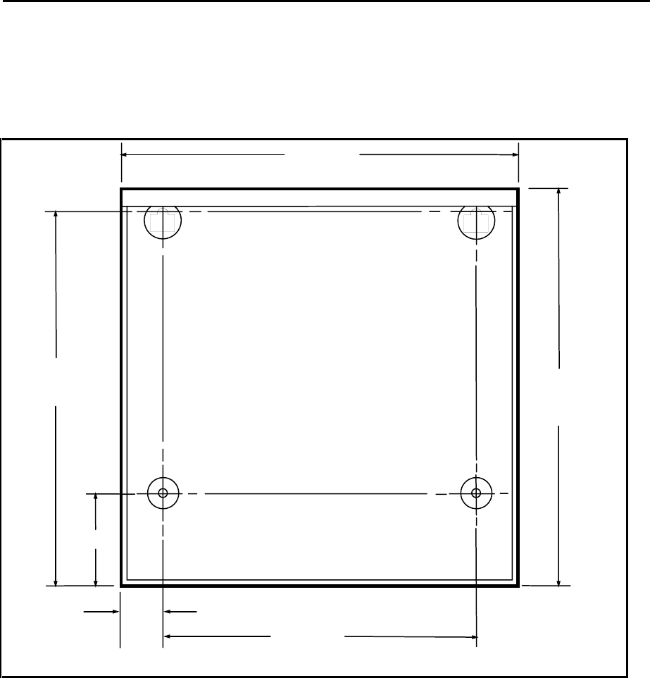
Interactive Technologies, Inc. © 1998 351 Installation and Reference Manual
38
4.2. Mounting the APM and Peripherals
❖ ❖ How to Mount the APM
Mount your APM on the secure side of the doors it will monitor. Use the dimensions shown in
Figure 4 for mounting your APM.
3.38"
13.88"
14.50"
14.50"
1.50"
11.50"
9148G04A.DS4
Figure 4: 351 Mounting Dimensions
Use the following guidelines when mounting your APM peripherals:
• Mount the peripherals according to the instructions provided with the manufacturer's
packaging.
• A reader or keypad must be mounted on the unsecure side of each door, near the door, at a
convenient height for users.

Interactive Technologies, Inc. © 1998 351 Installation and Reference Manual
39
4.3. Wiring the APM and Peripherals
Wire your APM and peripherals by connecting all devices as shown in Figure 5, 351 Wiring
Diagram.
4.3.1. Wiring Guidelines
Proper wiring connections and shielded cable grounding are essential for a reliable system. Poor
wiring connections, ground loops, or ungrounded shielded cable cause most system problems.
Warning: The APM enclosure should not be used as a pull box or pass-through for wiring
unrelated to your APM and its associated equipment.
4.3.2. Stripping Shielded Cable
When stripping the outer jacket off the shielded cable, carefully inspect the insulation on the wires
for any nicks or cuts. After the excess shield has been cut off, pull the outer jacket of the shielded
cable over any exposed shield. Only the shield wire should be exposed.
When preparing the individual wires, strip off 1/4” of insulation. Tightly twist the strands together
and tin the wire. Beware of loose strands of wire touching adjacent screw terminals, as they can
cause problems.
4.3.3. Grounding Shielded Cable
Throughout the system, shielded cable must be properly grounded to prevent noise or ground
loops. The ground screw for the enclosure is terminal 3. This terminal must be connected to a
known ground (incoming power ground, telephone system ground, cold water pipe, or grounding
rod) for proper operation. Connect the shield wire of a shielded cable to the nearest ground
terminal on the APM's terminal strip.
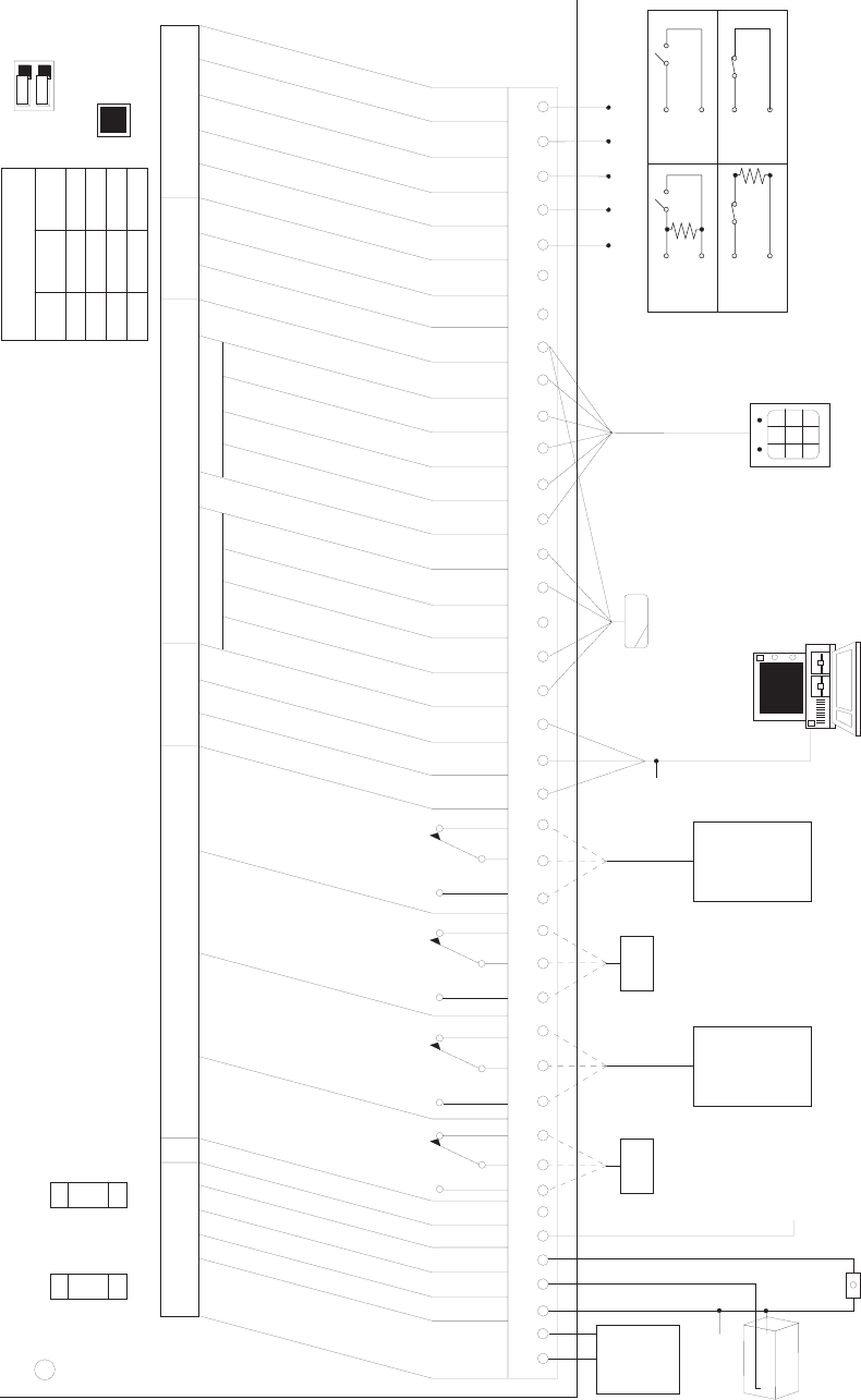
Interactive Technologies, Inc. © 1998 351 Installation and Reference Manual
40
1
PRIMARY POWER
GROUND
BACKUP BATTERY
TAMPER
+12V POWER OUTPUT, SEE NOTE 2
NOT USED
RELAY 1
DOOR 1 STRIKE
RELAY 2
DOOR 1 AUXILIARY
RELAY 3
DOOR 2 STRIKE
RELAY 4
DOOR 2 AUXILIARY
TRANSMIT DATA (TO TERMINAL)
RECEIVE DATA (FROM TERMINAL)
GROUND
DATA-1 OR M.S. DATA
DOOR 1 READER
DATA-0 OR M.S. CLOCK
KEYPAD
READER LED
+5V READER POWER, SEE NOTE 2
DOOR 2 READER
DATA-0 OR M.S. CLOCK
DATA-1 OR M.S. DATA
KEYPAD
READER LED
+12V READER POWER, SEE NOTE 2
GROUND
FUTURE USE
FUTURE USE
INPUT 1, DOOR 1 POSITION
INPUT 2, DOOR 1 EGRESS
INPUT 3, DOOR 2 POSITION
INPUT 4, DOOR 2 EGRESS
GROUND
POWER RELAY OUTPUT POINTS RS232
TERMINAL
PORT CARD READERS/KEYPADS INPUT
POINTS
AC
OR
DC
+
-
+
-
NO
C
NC NO
C
NC NO
C
NC NO
C
NC
16 VAC
OR
18-24 VDC
POWER
SUPPLY
BATTERY
+
-
TO EARTH
GROUND
DOOR 1
STRIKE
DOOR 1
AUXILIARY
DEVICE
OR
GENERAL-
PURPOSE
OUTPUT
DOOR 2
STRIKE
DOOR 2
AUXILIARY
DEVICE
OR
GENERAL-
PURPOSE
OUTPUT
49-334
TAMPER
SWITCH
PROGRAMMING
TERMINAL
DOOR 1
CARD READER
(OR WIEGAND
KEYPAD)
PRIMARY
POWER
FUSE
3A
FASTACTING
BATTERY
FUSE
2A
FASTACTING
POWER
ON
CLEAR
MEMORY
(SEE NOTE 1)
TERMINAL
BPS
1
2
GREEN
WHITE
BLACK
12V DC OUTPUT
(SEE NOTE 2)
WARNING: For continued protection against
the risk of fire, replace only with
the same type and rating fuse.
Notes: 1) To clear memory:
Press and hold the clear memory
button until the power indicator
goes out (about 5 seconds) then
release.
2) Total current sourced from terminals
6, 27, and 32 must not exceed 600 mA.
300
1200
2400
9600
OFF
ON
ON
OFF
OFF
OFF
ON
ON
DIP
SWITCH 1 DIP
SWITCH 2
TERMINAL PORT BPS
TABLE
9148G01B.DSF
ON
4.7K EOL RESISTORS
ARE REQUIRED FOR
SUPERVISED INPUTS.
CONTACTS MAY BE
N.O. OR N.C.
INPUT
GND
INPUT
GND
INPUT
GND
INPUT
GND
SUPERVISED NON-SUPERVISED
NORMALLY
OPEN
NORMALLY
CLOSED
DOOR 2
WIEGAND
KEYPAD
(OR CARD
READER)
2 3 4 5 6 7 8 9 10 11 12 13 14 15 16 17 18 19 20 21 22 23 24 25 26 27 28 29 30 31 32 33 34 35 36 37 38 39 40
Figure 5: 351 Wiring Diagram

Interactive Technologies, Inc. © 1998 351 Installation and Reference Manual
41
CAUTION! DO NOT apply power or connect backup batteries to your 351 yet!
❖ ❖ Wiring the APM and Peripherals
1. Wire your APM and peripherals as shown in Figure 5, 351 Wiring Diagram.
2. Connect the power supply cables (but do not apply power) and connect the grounding wire.
Warning: Do NOT connect the backup battery at this time.
3. Connect the output devices.
4. Connect the terminal and set the baud rate switches.
5. Connect the card readers and/or keypads.
6. Connect the input devices.
Note: Installation and wiring should be done in accordance with the National Electrical Code ,
NFPA No. 70, and any other applicable state or local codes.
4.4. Wiring the Power Supply and Grounding
Warning: Do not apply power to your APM or connect the backup battery yet! Only connect
the power supply cable to your APM now.
The APM's main electronics module can be powered two ways:
• AC— 16 VAC, 50/60 Hz
• DC— 18-24 VDC
Proper earth grounding must be used with either type of power source. Refer to Figure 6 or Figure
7 when making the power supply connections.
4.4.1. Wiring an AC Power Supply
1. Connect the AC terminals of the power transformer to terminals 1 and 2.
2. Connect the ground terminal on the transformer to terminal 3.
Warning: Do not plug the transformer into the AC power supply at this time.
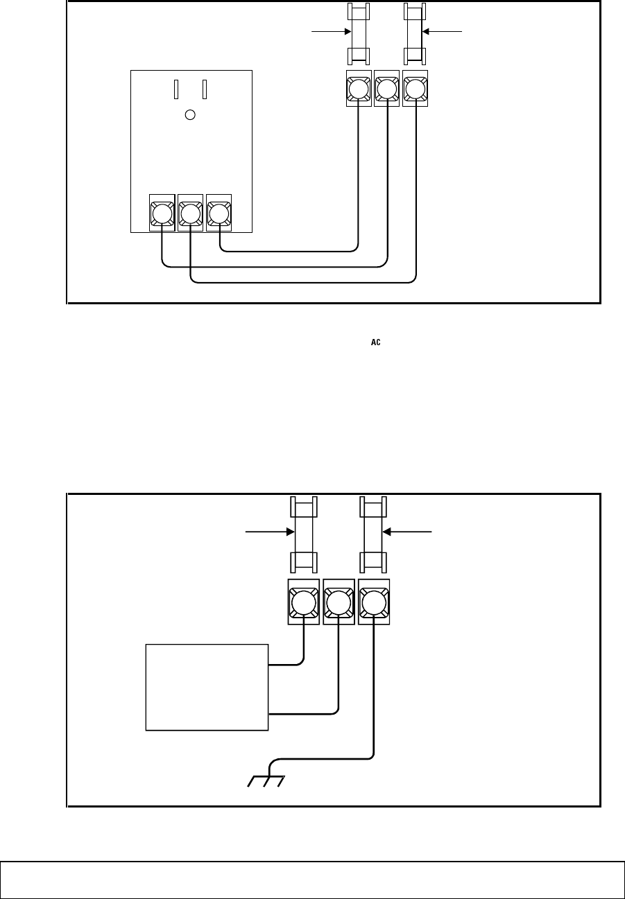
Interactive Technologies, Inc. © 1998 351 Installation and Reference Manual
42
12 3
PRIMARY
POWER FUSE
3 A
FAST ACTING
BATTERY FUSE
2 A
FAST ACTING
AC AC
GND
9148G07A.DS4
Figure 6: Wiring a 16 V Power Supply
4.4.2. Wiring a DC Power Supply
1. Connect the AC terminals of the power transformer to terminals 1 and 2.
2. Connect terminal 3 to a proper ground.
Warning: Do not connect the DC power supply at this time.
12 3
PRIMARY
POWER FUSE
3 A
FAST ACTING
BATTERY FUSE
2 A
FAST ACTING
DC POWER
SUPPLY
18-24 VDC
2.0 A MAX.
+
-TO
EARTH
GROUND
9148G08A.DS4
Figure 7: Wiring a DC Power Supply
CAUTION! The DC power source MUST have a voltage output between 18 and 24 or the
APM's power supply can be damaged.

Interactive Technologies, Inc. © 1998 351 Installation and Reference Manual
43
4.5. Wiring the Outputs
The APM controls four outputs:
• Outputs 1 and 3 are used to control the door strikes.
• Outputs 2 and 4 are used for APM options, interlocking, or other general-purpose outputs.
All of the output contacts are voltage-free, Form C type, rated at 3 Amps, 24 VAC or 30 VDC.
❖ ❖ How to Wire the Outputs
Complete the connections shown in Table 3. Refer to Figure 5, 351 Wiring Diagram, for the
location of these connections. Specific wiring for the strike(s) depends on the type of lock used.
Follow the manufacturer's instructions for the lock used.
Some examples of strikes are shown in Figure 8 and Figure 9 (found later in this section).
Note: Wire a diode across all DC-powered strikes or other inductive devices (see Figure 8 and
Figure 9).
Output Device Terminal
Connections
1 Door 1 Strike 8, 9, 10
2 Device used with another general output device. 11, 12, 13
3 Door 2 Strike 14 15 & 16
4 Device used with another general output device. 17, 18, 19
Table 3: The Output Connections
Note: When powering up the APM, all outputs are set to OFF.
CAUTION! The total power consumption of all external devices (strikes, outputs, readers,
etc.) must not exceed 600 mA at 12 VDC.
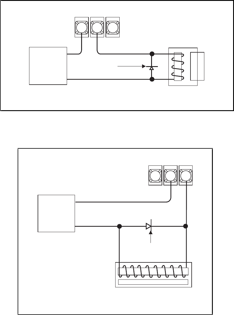
Interactive Technologies, Inc. © 1998 351 Installation and Reference Manual
44
8910
351
APM
24 VDC
POWER
SUPPLY
+
-
1N4002
OR
EQUIVALENT
STRIKE
9148G05A.DS4
Figure 8: Normally Open Strike at Door 1
14 15 16
351
APM
DC
POWER
SUPPLY
+
-
9148G06A.DS4
MAGNETIC LOCK
1N4002
OR
EQUIVALENT
Figure 9: Magnetic Strike at Door 2

Interactive Technologies, Inc. © 1998 351 Installation and Reference Manual
45
4.6. Wiring the Terminal
Each APM requires an RS-232 terminal or a computer with terminal emulation software for
programming and displaying events. Setting up the terminal includes wiring the terminal to your
APM and setting two DIP switches on the APM. The DIP switches are located near the upper
right of the inside of your APM (see Figure 5, 351 Wiring Diagram) and indicate the baud rate for
the terminal.
❖ ❖ How to Wire the Terminal
Connect the cable (ITI P/N 49-334) to the terminal block and to your APM terminals 20 (green
wire), 21 (white wire), and 22 (black wire). Refer to Figure 5, 351 Wiring Diagram, for the
location of these connections.
The maximum recommended cable length between your APM and the terminal is 50 feet. ITI
recommends the use of modems (80-067) for distances greater than 50 feet.
Note: Communications with the terminal are possible at distances greater than 50 feet.
However, these communications do not conform to the EIA RS232C specification and
are not recommended by ITI.
❖ ❖ How to Set the DIP Switches for the Terminal
Use the appropriate setting in Table 4 to set the terminal baud rate:
Baud
Rate
DIP Switch 1 DIP Switch 2
300 OFF OFF
1200 OFF ON
2400 ON OFF
9600 ON ON
Table 4: The Terminal Baud Rate DIP Switch Settings
4.6.1. Configuring the Terminal
Configure the terminal to be used to program the APM.
Note: Depending on the terminal used, configuration can mean setting DIP switches or
running a configuration/setup program.

Interactive Technologies, Inc. © 1998 351 Installation and Reference Manual
46
If the terminal is a computer with terminal emulation software, ensure that the configuration
matches the requirements below.
❖ ❖ How to Configure the Terminal
Follow the instructions provided in the terminal's manual. Configure the terminal setting as is
indicated below:
Parameter Setting
Baud Rate 300, 1200, 2400 or 9600
Word Size 7 bits
Parity Even
Flow Control XON / XOFF
Stop Bits 1
Duplex Full
Table 5: Terminal Configuration Settings
❖ ❖ How to Install the Database Backup Software
Follow the instructions provided with the software.
4.7. Wiring the Readers and/or Keypads
Each door must have a Wiegand or magnetic-stripe format reader and/or a keypad. When
completing reader or keypad connections, refer to Figure 5, 351 Wiring Diagram.
❖ ❖ How to Wire Readers
Follow the instructions provided with the reader packaging. For ITI magnetic-stripe and Wiegand
readers, use the following specifications for cabling:
• 0 to 50 feet— 24 AWG shielded cable (Belden 9535 or equivalent).
• 50 to 500 feet— 18 AWG shielded cable (Belden 9553 or equivalent).
❖ ❖ How to Wire Keypads
Follow the installation instructions included with the Keyboard Option Kit.

Interactive Technologies, Inc. © 1998 351 Installation and Reference Manual
47
4.8. Wiring the Inputs
The APM monitors four inputs. Each input requires a single pole, single throw (SPST), normally
open or normally closed, voltage-free contact.
The inputs are used for the door sensors position sensors and exit buttons. Each of the inputs can
be supervised by installing end-of-line resistors.
❖ ❖ How to Wire the Inputs
Complete the connections in Table 6. Refer to Figure 5, 351 Wiring Diagram, for the locations of
these connections.
Input Device
Terminals
1 Door 1 Position Sensor
36 & 38
2 Door 1 Exit Button
37 & 38
3 Door 2 Position Sensor
38 & 39
4 Door 2 Exit Button
38 & 40
Table 6: The Input Connections
4.9. Applying Power
When all steps for mounting and wiring are completed, you are nearly ready to apply power to the
APM. Complete the prepower checklist before applying power.
CAUTION! Do not apply power to your APM until completing the prepower checklist!
4.9.1. Prepower Checklist
Confirm each of the following items before powering up the APM.
❏ The APM is mounted on the secure side of the door.
❏ The card reader (s) and/or keypads are mounted as specified in the Option Kit instructions.
❏ Terminal 3 is properly grounded.
❏ All shielded cables are properly grounded.
❏ All screw terminals are tightened.
❏ The door strike wiring is run in a separate cable.
❏ A diode has been placed across any DC-operated strikes and any other inductive devices.
❏ The power source cable has been wired, but is not plugged in.
❏ The baud rate DIP switch has been set properly.

Interactive Technologies, Inc. © 1998 351 Installation and Reference Manual
48
4.9.2. Powering Up
The following procedure defines how to apply power to your APM for the first time.
Warning: Memory must be cleared when powering up the APM.
❖ ❖ How to Power Up an APM
1. Plug in your APM’s AC or DC power supply.
2. Hold down the [Clear Memory] button until the green power light, located on the left inside
of the unit, blinks. (Refer to Figure 5, 351 Wiring Diagram, for the location of the button and
power light.)
4.10. Wiring the Backup Battery
Optionally, your APM uses one l2-Volt, 6-Amp hour backup battery (ITI P/N 34-006). A float-
type battery charger is included in your APM power supply.
❖ ❖ How to Wire the Backup Battery
Connect the battery to terminals 3 and 4. Refer to Figure 5, 351 Wiring Diagram, for the location
of these connections.
Note: The battery charger supplies up to 500 mA to the battery. How long your APM works
depends upon the battery’s condition and the load on the APM.
4.10.1. Testing Communications
After powering up the APM, use the following procedure to test communications.
Note: If your APM does not respond as described in the following procedure, go to Section 9,
“Testing and Troubleshooting,” for help identifying and resolving the problem.
Interactive Technologies, Inc. © 1998 351 Installation and Reference Manual
49
❖ ❖ How to Test Communications
1. Verify the following things to test communications:
• The APM power light is on.
• The power indicator on the reader LED (light-emitting diode) is red.
• If keypads are used, the Ready LED is on.
• The terminal displays the following message:
PRIMARY POWER RESTORED
• followed by a statement about the database (INTACT or LOST) and a statement about the
backup battery (LOW or OK).
2. Type a few random characters on the terminal. All characters typed should appear
on your display.
Note: All letters typed will appear only in uppercase.
3. Press [Rtn]. The BAD COMMAND message should display on the next line.
4. Log on to your APM and print the Full APM report. To do this, refer to the instructions in
Section 6.

Interactive Technologies, Inc. © 1998 351 Installation and Reference Manual
50
5. Introduction to Programming
The following section introduces general procedures and conventions used to enter commands
into your APM. Commands are used to set up your APM configuration, maintain the cardholder
database, and control system devices.
5.1. Programming Conventions
The following conventions are always used during programming.
Note: Uppercase (capital) letters must be used at all times when programming. Press the [Caps
Lock] button on to ensure the use of uppercase letters.
5.1.1. The Ready> Prompt
The Ready> prompt is displayed when your APM is ready to receive a command.
5.1.2. Aborting Commands
When programming, press the [Esc] key at any time to quit the current command. After pressing
[Esc], the message ABORTED appears. Press [Rtn] to return to the Ready> prompt.
5.1.3. Command Responses
When a command is entered correctly, your APM displays an OK message, like this:
01/01/97 MO 12:00 APM_1 - OK
When a command is not entered correctly, your APM displays an error message, like this:
FORMAT ERROR (R-retry)>
Note: For a complete list of APM error messages, refer to Appendix E, “APM Error
Messages.”

Interactive Technologies, Inc. © 1998 351 Installation and Reference Manual
51
5.2. List of APM Commands
Command Function
Command
Page #
Used By
Installers
Used By
Owners
Command Entry Mode
Enter command entry mode.
LOGON
52
✔
✔
Exit command entry mode.
LOGOFF
53
✔
✔
Accessing Information on the APM
Print reports on APM
configuration or cardholder
information.
REP
54
✔
✔
List of all programming
commands.
HELP
53
✔
✔
Basic APM Setup
Set the name to the APM.
APM
65 ✔
Set the current date.
DATE
65 ✔
Set the current time.
TIME
66 ✔
Set up of APM Schedules
Set up holiday schedules.
HOL
67 ✔
Enter the time schedules for
cardholders and input and output
devices.
TS
68 ✔
Schedule time changes to/from
daylight saving time.
DLS
70 ✔
Set up of APM Hardware
Define the door strike settings.
DOOR
71
✔
Define input and outputs.
IO
72
✔
Select options for outputs 2 or 4.
OPT
74
✔
Set panic option timer values.
PANIC
77
✔
Set the card readers
RDR
77
✔
Miscellaneous Types of Setup Commands
Change your APM password.
PSW
78 ✔
Set your APM site code.
SC
79
✔
Set the magnetic-stripe card
reader format.
SETMAG
79
✔

Interactive Technologies, Inc. © 1998 351 Installation and Reference Manual
52
Setting Up Card Access
Enter and maintain cardholder
information.
DBASE 84-87 ✔
Set up Master Learn / Delete
Cards to add and delete cards at
the card reader.
LEARN 89-90 ✔
System Control Commands
Lock or unlock the card readers
or keypads.
LOCK 82 ✔
Turn an output on, off, or pulse it. REL 81 ✔
Command Reference 1: APM Command Table
5.3. Command Entry Mode
The APM is normally in a secure state that will not accept commands. In order to program the
APM the user must log on to enter command entry mode. Logging into this mode requires a
password to prevent unauthorized access.
After programming is finished, you return your APM to the secure state by logging off.
Note: If you do not type anything for two minutes, your APM will automatically log off into the
secure state.
5.3.1. Entering Command Entry Mode: LOGON
The LOGON command allows you to program your APM. To prevent unauthorized access, this
command requires a password to enter command entry mode.
Each APM has a default password, ITI351. However, this password should be changed after
installation. Changing the password is done with the PSW command, found later in this section.
Prompt Response
How to log onto the APM:
Ready> Type LOGON and press [Rtn].
ENTER YOUR PSW> Type the password and press [Rtn].
Note: As you type each character, the terminal displays an X to protect your
password.
Note: The default password is ITI351.
Command Reference 2: LOGON

Interactive Technologies, Inc. © 1998 351 Installation and Reference Manual
53
5.3.2. Obtaining a List of Commands: HELP
The HELP command lists available commands. This provides an on-line reference to available
commands while programming the APM.
Prompt Response
To use the HELP command:
Ready> Type HELP and press [Rtn].
A complete command list will be displayed.
To stop the scrolling list, press Ctrl + S.
To start the list scrolling again, press Ctrl + Q.
Command Reference 3: HELP
5.3.3. Exiting Command Entry Mode: LOGOFF
To leave command entry mode, you must log off with the LOGOFF command. Use this command
whenever you are done programming. Remember, your APM will automatically log off after 2
minutes of inactivity.
Prompt Response
How to log off of APM:
Ready> Type LOGOUT and press [Rtn].
Command Reference 4: LOGOFF
Note: Although the terminal prompt is “Ready,” you must use the
LOGON
command. No
entries are possible until a valid
LOGON
occurs.
5.4. General Procedure for Entering Commands
Entering commands generally involves first logging on, issuing commands, responding to each
command prompt, and logging off when finished.
Prompt Response
How to type general commands into your APM:
Ready> Type LOGON and press [Rtn].
ENTER YOUR PSW> Type the password and press [Rtn].
Ready> Type the appropriate command and press
[Rtn].
… Respond to each prompt. (The commands all
have varying prompts.) …
Ready> When finished programming, type LOGOFF
and press [Rtn].
Command Reference 5: General Procedure for Entering Commands

Interactive Technologies, Inc. © 1998 351 Installation and Reference Manual
54
6. Reports
The REP command is used to generate reports. Reports are used to display your APM
configuration, stored events, or cardholder information.
You can generate several types of reports on your APM:
• Full— Displays your APM configuration, including settings for inputs, outputs, doors,
time schedules, site code, and Master Learn / Delete Cards.
• Event— Lists all events stored in the APM.
• Cardholder— Searches for and lists cardholders in the database. A search can be by card,
PIN, name, or category.
6.1. Full Report
The Full Report, which you select by entering the Full option from the REP command, displays
all current APM settings
Prompt Response
How to display a Full Report:
Ready> Type REP and press [Rtn].
B-badge N-name F-full
C-cat E-events> Type F (for Full Report) and press [Rtn].
To stop the scrolling, press Ctrl + S.
To start the list scrolling again, press Ctrl + Q.
Command Reference 6: Full Report
Note: Always print a copy of the Full Report before changing your APM settings.

Interactive Technologies, Inc. © 1998 351 Installation and Reference Manual
55
03/06/97 TH 13:04 NCS FULL REPORT
SYSTEM 351 V1.2 (C) 1996 ITI
POWER:
PRIMARY-OK
BATTERY-LOW
INPUTS:
EAST_POS TROUBLE Y NC SUP INTERLOCKED
INPUT2 NORMAL Y NO NON-SUP
WEST_POS TROUBLE Y NO SUP INTERLOCKED
INPUT4 NORMAL Y NO NON-SUP
OUTPUTS:
EAST_STK OFF Y
EAST_CCTV ON D
WEST_STK OFF Y
WEST_CCTV ON D
LOCK STATUS-UNLOCKED
TIME SCHEDULES:
A 00:00-07:59 --:-- --:-- MO,TU,WE,TH,FR,SA,SU
23:45-23:59 08:00-08:14 MO,TU,WE,TH,FR,SA,SU
--:-- --:-- --:-- --:--
--:-- --:-- --:-- --:--
B 08:00-15:59 --:-- --:-- MO,TU,WE,TH,FR,SA,SU
07:45-07:59 16:00-16:14 MO,TU,WE,TH,FR,SA,SU
--:-- --:-- --:-- --:--
--:-- --:-- --:-- --:--
C 16:00-23:59 --:-- --:-- MO,TU,WE,TH,FR,SA,SU
15:45-15:59 00:00-00:14 MO,TU,WE,TH,FR,SA,SU
--:-- --:-- --:-- --:--
--:-- --:-- --:-- --:--
D 06:30-17:29 --:-- --:-- MO,TU,WE,TH,FR,
10:00-15:59 --:-- --:-- SA,SU,HO
--:-- --:-- --:-- --:--
--:-- --:-- --:-- --:--
HOLIDAYS
1: 05/26/97 00:00 05/26/97 23:59 variable
2: 09/01/97 00:00 09/01/97 23:59 variable
3: 12/24 00:00 12/25 23:59 fixed
4: 12/31 00:00 01/01 23:59 fixed
DAYLIGHT SAVINGS:
1: 04/06 02:00 03:00
2: 10/26 02:00 01:00
OPTIONS:
EAST_CCTV
WIRELESS - LIGHTS
DENIED ACCESS - DOOR_EAST
WEST_CCTV
WIRELESS - STAR
DENIED ACCESS - DOOR_WEST
PANIC:
INITIAL ON TIME=30
TIME-OUT=240

Interactive Technologies, Inc. © 1998 351 Installation and Reference Manual
56
DOORS:
DOOR_EAST
STRIKE TYPE = FIXED TIME
STRIKE TIME = 10
AJAR TIME = 10
DOOR_WEST
STRIKE TYPE = FIXED TIME
STRIKE TIME = 10
AJAR TIME = 10
SITECODE=0
READER TYPE - wiegand
READER LED TYPE - red/green
LEARN CARDS:
ADD:
A=215574 NAME=SHIFT_A TS1=A TS2=A CAT=A A/D=N PC=Y
B=215575 NAME=SHIFT_B TS1=B TS2=B CAT=B A/D=N PC=Y
C=215576 NAME=SHIFT_C TS1=C TS2=C CAT=C A/D=N PC=Y
D=215577 NAME=REGULAR TS1=D TS2=D CAT=R A/D=N PC=Y
DELETE:
E=215579
7 IDS IN DBASE
CARDHOLDER DBASE 2% FULL
03/06/97 TH 13:05 NCS END FULL REPORT
Example 15: The Full Report
6.1.1. Power
This Full Report section indicates the information about your APM’s power sources:
• Primary— The status of the primary power source (OK or NONE).
• Battery— The status of the backup battery (OK or LOW).
6.1.2. Inputs
This Full Report section indicates the settings for each input:
• Input Name— Default names are INPUT1, INPUT2, etc.
• Status— NORMAL or ALARM; if the input is supervised, the alarm status can also be
TROUBLE.
• Schedule— The time schedules assigned to the input.
• Contact Type— Normally Open (NO) or Normally Closed (NC).
• Supervision— Supervised (SUP) or nonsupervised (NON-SUP).
Interactive Technologies, Inc. © 1998 351 Installation and Reference Manual
57
6.1.3. Outputs
This Full Report section indicates the settings for each output:
• Output Name— Default names are OUTPUT1, OUTPUT2, etc.
• State— ON or OFF.
• Schedule— The time schedules assigned to the output.
6.1.4. Lock Status
This Full Report field indicates whether the card readers and/or keypads are locked (disabled) or
unlocked.
6.1.5. Time Schedules
This Full Report section indicates the user-defined time schedules:
• Schedule— The letter assigned to the time schedule (A-D).
• Intervals— When each interval in the schedule begins and ends.
• Days— MO, TU, WE, TH, FR, SA, SU, and/or HO (holidays).
6.1.6. Holidays
This Full Report section indicates the assigned holidays and their settings:
• Number— System-assigned number (1-10).
• Start— The start date and start time
• End— The end date and end time.
• Type— FIXED or VARIABLE
6.1.7. Daylight Savings
This Full Report section indicates the dates and times when automatic time changes are
scheduled:
• Number— System-assigned number (1 or 2).
• Date— The date the time change will go into effect.
• Old Time— The time the change will take place.
• New Time— The time after the change.
Interactive Technologies, Inc. © 1998 351 Installation and Reference Manual
58
6.1.8. Options
This Full Report section indicates the options selected for outputs 2 and 4:
• If no options are selected for an output, NONE is displayed.
• If any of the options are selected, each is listed (INTERLOCKING, DENIED ACCESS,
SECURITY SYSTEM ARM/DISARM, PANIC, WIRELESS POINT CONTROL, ,or
OCCUPANCY MONITORING).
• If Denied Access is selected, the associated door is also displayed.
• If Occupancy is selected, the associated door is also displayed. Occupancy also displays
the current and maximum number of occupants, and whether the reader is locked when the
maximum is reached.
6.1.9. Doors
This Full Report section indicates the settings for each door:
• Strike Type— Either MEMORY, NON-MEMORY, or FIXED.
• Strike Time— The number of seconds this door is unlocked after valid access.
• Ajar Time— The number of seconds that a door can be held open, after the strike time,
without causing an alarm.
6.1.10. Panic
This Full Report field indicates the settings for the panic timer:
• Initial On Time— The number of seconds the panic output must remain on.
• Time Out— The number of seconds when the panic output will turn off.
6.1.11. Site Code
This Full Report field indicates the current setting for your APM site code.
6.1.12. Reader Type
This Full Report field indicates the type of reader used at your APM. Readers are either Wiegand
or magnetic stripe.
6.1.13. Reader Led Type
This Full Report field indicates the setting for the type of LED used at your APM. Reader LED
types are either red only or red and green.

Interactive Technologies, Inc. © 1998 351 Installation and Reference Manual
59
6.1.14. Master Learn / Delete Cards
This Full Report section indicates the information about Master Learn / Delete Cards:
• Card Identifier— A, B, C, D, or E.
• Number— The number for the Master Learn / Delete Card.
Master Learn / Delete Cards also display the following attributes, which will be assigned to cards
added to the database at the reader:
• Schedules— TS1 and TS2 are the time schedules assigned for door 1 and door 2.
• Category— The category assigned to the cards.
• Name— The name assigned to the cards.
• Privileges— Y (yes) or N (no) for whether the cards are given Security System
Arm / Disarm (A/D) or Wireless Point Control (PC).
6.1.15. NUMBER OF IDS IN DBASE
This Full Report field indicates the number of cardholders in the database. It is displayed in the
format (#) IDS IN DBASE.
6.1.16. Cardholder Database Percentage Full
This Full Report field indicates the percentage of the cardholder database that is currently full. It
is displayed in the format CARDHOLDER DBASE (#)% FULL.
6.2. Event Reports
The Event Report lists up to 250 events that are stored in the memory. Events included in Event
Reports are power changes, alarm conditions, and access events.
Prompt Response
How to display an Event Report:
Ready> Type REP and press [Rtn].
B-badge N-name F-full
C-cat E-events> Type E (for Event Report) and press [Rtn].
To stop the scrolling list, press Ctrl + S.
To start the list scrolling again, press Ctrl + Q.
Command Reference 7: Event Report

Interactive Technologies, Inc. © 1998 351 Installation and Reference Manual
60
Ready> REP E
03/06/97 TH 12:08 NCS EVENT REPORT
01/01/96 MO 12:00 NCS PRIMARY POWER RESTORED
01/01/96 MO 12:00 NCS RESTART DATABASE LOST *
01/01/96 MO 12:00 NCS BATTERY LOW *
03/05/97 WE 13:27 NCS CCTV_EAST ON crd=92764 SINKULA_DAVE^35
03/05/97 WE 13:27 NCS DOOR_EAST crd=92764 SINKULA_DAVE^35
03/05/97 WE 13:29 NCS CCTV_EAST OFF crd=92764 SINKULA_DAVE^35
03/05/97 WE 13:29 NCS CCTV_WEST ON crd=92764 SINKULA_DAVE^35
03/05/97 WE 13:29 NCS CCTV_EAST OFF crd=92764 SINKULA_DAVE^35
03/05/97 WE 13:30 NCS DOOR_WEST crd=92764 SINKULA_DAVE^35
03/06/97 TH 12:09 NCS END EVENT REPORT
Example 16: An Event Report
6.3. Cardholder Reports
The Cardholder Reports lists information about cardholders by card number, PIN, name, or
category.
6.3.1. Category Reports
A Category Report is used to search for a group of database entries by the category attribute. The
report can be generated with the actual list of cardholders or as a summary of the number of
cardholders in the category.
Note: A complete listing of all cardholders in a database can be obtained by using the wild
card category (*).
Prompt Response
How to display a category report:
Ready> Type REP and press [Rtn].
B-badge N-name F-full
C-cat E-events> Type C (for Category Report) and press [Rtn].
LIST (Y-yes N-no)> Type Y and press [Rtn] to list each cardholder,
or type N and press [Rtn] for a summary of all
cardholders.
CATEGORY (a-z,*=all)> Type the letter of the desired category and press [Rtn],
or type * (the wild card character) for a list of all
cardholders and press [Rtn].
Command Reference 8: Category Report

Interactive Technologies, Inc. © 1998 351 Installation and Reference Manual
61
Ready> REP C,Y,*
03/06/97 TH 12:03 NCS CATEGORY REPORT
PIN CARD TS1 TS2 CAT ARM/DIS PT CTRL NAME
5804 D D R N Y SINKULA_DAVE^26
17925 A Y A N Y MOORE_PAUL
17926 B B B N Y FORTE_BOB
17927 C C C N Y WETTERLIND_ERIC
17930 D D M Y Y DEEN_FRED
46382 D D R N N SINKULA_DAVE^29
92764 D D R N N SINKULA_DAVE^35
7 ID (S) IN CATEGORY
03/06/97 TH 12:03 NCS END CATEGORY REPORT
Example 17: The Category Report (for All Categories)
Ready> REP C,Y,R
03/06/97 TH 12:03 NCS CATEGORY REPORT
PIN CARD TS1 TS2 CAT ARM/DIS PT CTRL NAME
5804 D D R N Y SINKULA_DAVE^26
46382 D D R N N SINKULA_DAVE^29
92764 D D R N N SINKULA_DAVE^35
3 ID (S) IN CATEGORY
03/06/97 TH 12:03 NCS END CATEGORY REPORT
Example 18: The Category Report (for One Category)
6.3.2. Cardholder Attributes
Each cardholder database entry has the following attributes:
• PIN— If used, the cardholder's personal identification number, such as the access code.
• Card Number— The cardholder's unique card identification number.
• Schedules— TS1 and TS2 are the time schedules assigned to this cardholder for door 1
and door 2.
• Category— The category to which this cardholder is assigned.
• Privileges— ARM/DIS and PT CTRL indicate if Security System Arm / Disarm or
Wireless Point Control privileges are assigned. The cardholder does have the privilege if a
Y is displayed; the cardholder does not have the privilege if an N is displayed.
• Name— The name of the cardholder.

Interactive Technologies, Inc. © 1998 351 Installation and Reference Manual
62
Ready> REP
B-badge N-name F-full C-cat E-events> C
LIST (Y-yes N-no)> Y
CATEGORY (a-z,*=all)> R
03/06/97 TH 12:03 NCS CATEGORY REPORT
PIN CARD TS1 TS2 CAT ARM/DIS PT CTRL NAME
5804 D D R N Y SINKULA_DAVE^26
46382 D D R N Y SINKULA_DAVE^29
92764 D D R N Y SINKULA_DAVE^35
3 ID (S) IN CATEGORY
03/06/97 TH 12:03 NCS END CATEGORY REPORT
Example 19: Category Report for a Single Category
Ready> REP
B-badge N-name F-full C-cat E-events> C
LIST (Y-yes N-no)> N
CATEGORY (a-z,*=all)> R
03/06/97 TH 12:03 NCS CATEGORY REPORT
3 ID (S) IN CATEGORY
03/06/97 TH 12:03 NCS END CATEGORY REPORT
Example 20: Category Report With No Listing

Interactive Technologies, Inc. © 1998 351 Installation and Reference Manual
63
6.3.3. Badge Reports
A Badge Report is used to search for a database entry by its card or PIN.
Prompt Response
How to display a Badge Report:
Ready> Type REP and press [Rtn].
B-badge N-name
F-full C-cat
E-events>
Type B (for Badge Report) and press [Rtn].
To stop the scrolling list, press Ctrl + S.
To start the list scrolling again, press Ctrl +Q.
P-pin C-card> Type the letter for the desired ID (either P or C) to
search for and press [Rtn].
CARD #> If Card was selected: Type the card for the report and
press [Rtn].
PIN> If PIN was selected: Type the PIN for the report and
press [Rtn].
Command Reference 9: Badge Report
Ready> REP
B-badge N-name F-full C-cat E-events> B
P-pin C-card> C
CARD #> 17926
PIN CARD TS1 TS2 CAT ARM/DIS PT CTRL NAME
17926 B B B N Y FORTE_BOB
Example 21: Badge Report for a Card
Ready> REP
B-badge N-name F-full C-cat E-events> B
P-pin C-card> P
PIN> 1234
PIN CARD TS1 TS2 CAT ARM/DIS PT CTRL NAME
1234 17930 D D M Y Y DEEN_FRED
Example 22: Badge Report for a PIN

Interactive Technologies, Inc. © 1998 351 Installation and Reference Manual
64
6.3.4. Name Reports
A Badge Report is used to search for a database entry by cardholder name.
Prompt Response
How to display a Name Report:
Ready> Type REP and press [Rtn].
B-badge N-name
F-full C-cat
E-events>
Type N (for Name Report) and press [Rtn].
To stop the scrolling list, press Ctrl + S.
To start the list scrolling again, press Ctrl + Q.
NAME> Type the name of the cardholder and press [Rtn].
Command Reference 10: Name Report
Ready> REP
B-badge N-name F-full C-cat E-events> N
NAME> WETTERLIND_ERIC
PIN CARD TS1 TS2 CAT ARM/DIS PT CTRL NAME
17927 C C C N Y WETTERLIND_ERIC
Example 23: Name Report

Interactive Technologies, Inc. © 1998 351 Installation and Reference Manual
65
7. Programming Your 351
Programming commands are used to set up your APM configuration, maintain the cardholder
database , and control system devices.
7.1. Basic Setup Commands
7.1.1. APM Name: APM
The APM command assigns a name to an APM. This name appears on reports and events. The
name set at the factory is APX (where X is the unit number).
An APM name can be up to 10 characters long. Each character can be a number or letter, as well
as any of the following symbols:
: < = > ? @ [ \ ] ^ _ `
Prompt Response
Setting your APM name:
Ready> Type APM and press [Rtn].
ENTER NEW APM NAME> Type the new name and press [Rtn].
The name can be up to 10 characters long. It can
include numbers and letters, as well as the following
characters:
: < = > ? @ [ \ ] ^ _ `
Note: The first character in the name cannot be a number, and the name cannot
include spaces.
Command Reference 11: APM
7.1.2. Current Date: DATE
The current date is set using the DATE command. The command can also be used to display the
current date, time, and APM name.
Enter dates in mm/dd/yy format, where “mm” is the month, “dd” is the day, and “yy” is the year.
For example, enter “January 1,1994” as “01/01/94.”

Interactive Technologies, Inc. © 1998 351 Installation and Reference Manual
66
Prompt Response
Changing the date:
Ready> Type DATE and press [Rtn].
S-set R-read> Type S and press [Rtn].
DATE mm/dd/yy> Type today’s date in mm/dd/yy format (use leading
zeros) and press [Rtn].
Displaying the date:
Ready> Type DATE and press [Rtn].
S-set R-read> Type R and press [Rtn].
The date appears as follows:
01/01/97 MO 00:00
Command Reference 12: DATE
Note: The date value is used by your APM for event logging and in making date-based
decisions. Set your APM calendar to match the current date.
For dates, enter leading zeros for one-digit numbers, and do not omit the slashes.
7.1.3. Current Time: TIME
The TIME command is used to set the current system time. The command can also be used to
display the current date, time, and APM name.
Enter times as “hh:mm,” using the 24-hour format, where “hh” is the hour and “mm” is the
minute. For example, enter “1:05 AM” as “01:05” and enter “1:05 PM” as “13:05.”
Prompt Response
Setting the time:
Ready> Type TIME and press [Rtn].
S-set R-read> Type S and press [Rtn].
TIME hh:mm> Type the time in hh:mm format and press [Rtn].
Displaying the time:
Ready> Type TIME and press [Rtn].
S-set R-read> Type R and press [Rtn].
Command Reference 13: TIME
Note: Time is entered in 24-hour format (00:00 through 23:59).
Enter leading zeros for one-digit numbers and do not omit the colon.
Note: The time value is used by your APM for all event logging and all time-of-day-based
decisions. Because access times will not correspond to the actual time if the APM's time
is wrong, set your APM clock to match the current time.

Interactive Technologies, Inc. © 1998 351 Installation and Reference Manual
67
7.2. Schedule Setup Commands
7.2.1. Holidays: HOL
The HOL command adds or deletes a holiday interval for use with time schedules.
Each holiday interval has a start time, end time, start date, and end date can span more than one
day. For example, the New Year’s holiday could be from 12/31/97, 5 PM, to 1/2/98, 9 AM
Note: Up to 10 holidays intervals can be defined.
Enter dates in “mm/dd/yy” or “mm/dd” format, as indicated by the prompt, where “mm” is the
month, “dd” is the day, and “yy” is the year. For example, enter January 1,1994 as 01/01/94.
Enter times as “hh:mm” format, using the 24-hour time, where “hh” is the hour and “mm” is the
minute. For example, enter “1:05 AM” as “01:05” and enter “1:05 PM” as “13:05.”
Prompt Response
Adding a holiday:
Ready> Type HOL and press [Rtn].
A-add, D-delete> Type A and press [Rtn].
F-fixed V-var> Type F and press [Rtn] to add a fixed holiday,
or type V and press [Rtn] to add a variable holiday.
START DATE mm/dd> Type the date the holiday begins and press [Rtn].
For fixed holidays, use mm/dd format;
for variable holidays, use mm/dd/yy format.
START TIME
hh:mm> Type the time the holiday begins (in hh:mm format)
and press [Rtn]. Time is entered in a 24-hour format,
and leading zeros must be used.
END DATE
mm/dd> Type the date the holiday ends and press [Rtn].
Note: For fixed holidays, use mm/dd format;
for variable holidays use mm/dd/yy format.
(Continued)

Interactive Technologies, Inc. © 1998 351 Installation and Reference Manual
68
END TIME
hh:mm>
Type the time the holiday ends (in hh:mm format)
and press [Rtn]. Time is entered in a 24-hour format,
and leading zeros must be used.
Note: To verify your holiday additions, run a Full Report (see the “
REP
Command,”
in Section 6).
Deleting a holiday:
Note: You will need the holiday’s sequential number to delete the holiday. If you do
not know it, run a Full Report.
Ready> Type HOL and press [Rtn].
A-add,
D-delete>
Type D and press [Rtn].
HOLIDAY NUMBER
(1-10)>
Type the number of the holiday and press [Rtn].
Note: Holidays in a holiday schedule are renumbered whenever one is deleted. If you
plan to delete several holidays, we suggest you run a Full Report before deleting.
Command Reference 14: HOL
Note: For dates, enter leading zeros for one-digit numbers and do not omit the slashes.
For times, enter leading zeros for one-digit number, and do not omit the colon.
Note: To delete a holiday, its sequential number is needed. To obtain a holiday's sequential
number, run a Full Report.
7.2.2. Time Schedules: TS
The TS command is used to add, delete, or change time schedules.
Time schedules are assigned a reference letter. Schedules A through D are user definable with the
TS command. Schedules X (always) and Y (never) cannot be changed.
Note: Up to 4 time schedules can be defined.
Each time schedule includes up to four time zones, numbered 0 through 3. A time zone includes
one or two intervals of time, entered in the 24-hour format, when the schedule will be active. The
time schedule also includes the days of the week for which it applies.
The days of the week are numbered 1 through 7 starting with Monday. An “8th day” is defined as
all the holidays in the holiday schedule.
For example, if assigning the days 1 through 5 and 8 to a time zone, it will be active Monday
through Friday and on the scheduled holidays. Contiguous days are entered by using a hyphen
(Monday through Friday is entered 1-5). Separate days are denoted with semicolons (Monday,
Wednesday, Friday would be entered 1;3;5).

Interactive Technologies, Inc. © 1998 351 Installation and Reference Manual
69
Prompt Response
Adding a time schedule:
Note: Repeat the following steps for every time zone you want in the time schedule.
Ready> Type TS and press [Rtn]
A-add D-delete> Type A and press [Rtn]
TIME SCHEDULE
(A-D)> Type a letter (A-D) to name this time schedule and
press [Rtn].
TIMEZONE (0-3) Type a number (0-3) to identify this time zone and
press [Rtn].
TIME
hh:mm-hh:mm;...> Type one time interval, in the hh:mm-hh:mm
format, and press [Rtn].
Or, type two time intervals, in the
hh:mm-hh:mm;hh:mm-hh:mm format, and press
[Rtn].
DAYS (1-3,1-MO)> Type the numbers for the days of the week the
time zone will be valid and press [Rtn]
(1-7=Monday-Sunday; 8 = Holidays.)
You can enter a contiguous set of days by using a
hyphen (Monday through Friday is entered 1-5).
Separate days are denoted with semicolons
(Monday, Wednesday, Friday would be entered
1;3;5).
Note: Print a Full APM report to verify your time schedules are correct (see “
REP
Command” in this section).
Deleting a time schedule
Ready> Type TS and press [Rtn]
A-add D-delete> Type D and press [Rtn].
TIME SCHEDULE
(A-D)> Type the letter (A-D) of the time schedule and
press [Rtn].
S-single B-block> To delete multiple time zones, type S and press
[Rtn] to delete time zones from the schedule one
at a time
or type B and press [Rtn] to delete the schedule all
at once.
TIME ZONE (0-3)> To delete a single time zone, type the number of
the time zone (0-3) and press [Rtn].
Note: The “time zone” prompt applies only if you select “single.”
Command Reference 15: TS

Interactive Technologies, Inc. © 1998 351 Installation and Reference Manual
70
Note: Times are always inclusive; a time interval is active up to, and including, the start and
stop times. For example, a time interval from 00:00 to 11:59 is active from midnight to
noon.
Time intervals are active during the start and stop time. The start time must be earlier
than the end time. To span midnight, two intervals must be used.
Time zones assigned to holidays will only be used once the start time of the holiday
begins.
7.2.3. Daylight Savings Time Changes: DLS
The DLS command is used to set the dates and times for time changes, allowing your APM to
automatically adjust its internal clock.
Two dates can be set for time changes, typically these are used for:
• standard time to Daylight Savings Time and
• Daylight Savings Time to standard time.
Prompt Response
Adding an automatic time change (Daylight Savings Time):
Ready> Type DLS and press [Rtn].
A-add D-delete> Type A and press [Rtn].
DATE mm/dd> Type the date (in mm/dd format) when the time change
will go into effect and press [Rtn].
OLDTIME hh:mm> Type the time when the time change will go into effect
(in hh:mm format) and press [Rtn].
Note: Time is entered in a 24-hour format, and leading zeros must be used.
NEWTIME hh:mm> Type what the new time should be (in hh:mm format)
when the time change goes into effect and press [Rtn].
Deleting an automatic time change (Daylight Savings Time):
Ready> Type DLS and press [Rtn].
A-add D-delete> Type D and press [Rtn].
DLS (1 or 2)> Type the number of the time change to be deleted and
press [Rtn].
Note: “1” is the first time change entered, “2” is the second time change entered.
(These correspond to 1 and 2 shown in the previous report example.)
Command Reference 16: DLS

Interactive Technologies, Inc. © 1998 351 Installation and Reference Manual
71
7.3. Hardware Setup Commands
7.3.1. Door Setup: DOOR
The DOOR command is used to enter settings for each door, as follows:
• Name — A descriptive name for the door (optional).
• Strike type — Either memory, non-memory, or fixed.
• Strike time — The number of seconds that the door strike is unlocked during access.
• Ajar time — The number of seconds a door can be open, beyond the strike time, without
causing an alarm.
Note: The default strike time is 10 seconds.
The default ajar time is 10 seconds.
The total time the door can be open without generating an alarm is the strike time plus the ajar
time. Zero can be entered for either the strike time or the ajar time. However, a 0-second strike
time will not open the door at all. A memory strike door with a 0-second ajar time generates an
alarm every time the door is opened during a valid access.
Note: If no time value is entered for either the strike time or ajar time, your APM retains the
previously entered value.
Prompt Response
Entering door settings:
Ready> Type DOOR and press [Rtn].
DOOR NAME> Type the current door name and press [Rtn].
The default names are door_1 and door_2.
NEW NAME> To rename the door: type the new name and press
[Rtn].
STRIKE TYPE
(M-memory N-non-memory
F-fixed time)>
Type the letter for the type of door used and press
[Rtn].
DOOR STRIKE
TIME (0-99)> Type the time (0-99 seconds) that this door should
remain unlocked after a valid transaction and press
[Rtn].
Note: A strike time of 0 will not open the door.
DOOR AJAR TIME
(0-99)> Type the time (0-99 seconds) that this door can be
held open after a valid access without triggering an
alarm and press [Rtn].
Note: A memory strike door with a 0-second ajar time generates an alarm every time the
door is opened during a valid access.
Command Reference 17: DOOR

Interactive Technologies, Inc. © 1998 351 Installation and Reference Manual
72
7.3.2. Inputs and Outputs: IO
The IO command is used to make changes to input and output settings.
For inputs, the settings include the following:
• Point Name — Descriptive names, such as “hallmotion,” are helpful because point
names are listed in reports. The default names are INPUT1, INPUT2, etc.
The point name can be up to 10 characters long. It can include numbers and letters, as well
as the following characters:
: < = > ? @ [ \ ] ^ _ `
Note: The first character cannot be a number, and the name cannot include spaces.
• Time Schedule — A time schedule for an input defines when alarm messages are ignored
(shunted).
Note: The default time schedule for an input is Y (never).
• Contact Type — Defines whether the point is normally opened or normally closed.
• Supervised — A yes / no setting that indicates if the input is wired with a fixed resistor,
to distinguish between alarm or trouble conditions.
• Egress — A yes / no setting that indicates if the input is used for egress. If used for
egress, an alarm event at the input causes the door to unlock for the strike time. By default,
your system uses input 2 to unlock door 1 and input 4 to unlock door 2.
For outputs, the settings include the following:
• Point Name — Descriptive names, such as “camera,” are helpful because point names
are listed in reports. The default names are OUTPUT1, OUTPUT2, etc.
• Time Schedule — A time schedule for an output defines when the output will be active.
If the security system Arm / Disarm Option is used with output 2 or 4, see the DBASE
command, in Section 7.
Note: The default time schedule for an output is Y (never).
Prompt Response
Defining an output
Ready> Type IO and press [Rtn].
O-output I-input> Type O and press [Rtn] to enter settings for an output,
or type I and press [Rtn] to enter settings for an input.
POINT NAME> Type the current name for the point and press [Rtn].
Note: If you do not know the point’s current name, run a Full APM report. See “
REP
Command,” in the previous section.
(Continued)

Interactive Technologies, Inc. © 1998 351 Installation and Reference Manual
73
NEW NAME> If you are changing the point name, type the new
name and press [Rtn].
Otherwise, leave the field blank and press [Rtn].
Note: The first character cannot be a number, and the name cannot include spaces.
TIME SCHEDULE
(A-D,X,Y)> If you want to assign a time schedule for the point,
type the time schedule’s letter, and press [Rtn].
If you do not want to assign a time schedule to the
point, press [Rtn].
Defining an input:
Ready> Type IO and press [Rtn].
O-output I-input> Type I and press [Rtn] to enter settings for an input
POINT NAME> Type the current name for the point and press [Rtn].
Note: If you do not know the point’s current name, run a Full APM report. See “
REP
Command,” in the previous section.
NEW NAME> If you are changing the point name, type the new
name and press [Rtn].
Otherwise, leave the field blank and press [Rtn].
Note: The first character cannot be a number, and the name cannot include spaces.
TIME SCHEDULE
(A-D,X,Y)> If you want to assign a time schedule for the point,
type the time schedule’s letter, and press [Rtn].
If you do not want to assign a time schedule to the
point, press [Rtn].
CONTACT TYPE
(O-normally open
C-normally closed)>
Type O and press [Rtn] if this door contact is
normally open,
or type C and press [Rtn] if this door contact is
normally closed.
SUPERVISED
(Y-yes N-no)> Type Y and press [Rtn] if this is a supervised point,
or type N and press [Rtn] if this is a non-supervised
point.
EGRESS
(Y-yes N-no)> Type Y and press [Rtn] if the input will be used for
egress,
or Type N and press [Rtn] if the input will not be
used for egress.
Note: Only inputs 2 and 4 are allowed as egress points.
Command Reference 18: IO

Interactive Technologies, Inc. © 1998 351 Installation and Reference Manual
74
7.3.3. Options: OPT
CAUTION! The OPT command in previous releases deleted all of your option settings. In
the latest software release, multiple options can be selected. However,
exercise caution when doing this!
The OPT command allows you to select one or more of the following options. For more
information about APM options, see Section 2.
• Interlocking
• Denied Access
• Security System Arm / Disarm
• Panic
• Wireless Point Control
• Occupancy Monitoring
The OPT command issues a separate prompt for each option: a Y or a special selection enables the
option, N disables the option, and Q quits the OPT command. Pressing the [Rtn] key leaves that
particular option unchanged.
Both the Denied Access and Occupancy Monitoring Options can be associated with a door
(reader). The first prompt of the OPT command will be for the associated door. If neither of these
options are selected, the first prompt can be ignored by pressing the [Rtn] key.
The second prompt of the OPT command is for the output, which will be used for the option being
selected. This may be for either output 2 or output 4.
Interlocking— If interlocking is selected, an alarm event at the input activates the device wired
to the output. For example, if a motion detector is tripped, it is in the alarm state. Therefore, an
interlocked camera will turn on and record the identity of the person in that area. Interlocking can
be used from any input(s) to outputs 2, output 4, or to both.
To select Interlocking for an output, enter the input number (1-4) that the output will be
connected to. If two or more inputs are interlocked to the same output, repeat using the OPT
command for every input .
To clear a previously interlocked inputs, type N and press [Rtn]. This will clear all interlocked
inputs.
Denied Access— The Denied Access Option configures your APM to respond to an invalid
access attempt at a reader or keypad by pulsing (turning on briefly) output 2 or 4. This option can
be useful for facilities in where an alarm, camera, or other device is used to handle such access
attempts.
To select the Denied Access Option, you must select which door you want Output 2 or Output 4
activated from. When you select the door, the APM recognizes access attempts only at that door’s
reader. In the event of an invalid access attempt at a door with the Denied Access Option, the
output will be activated for 10 seconds.
To clear this option, type N and press [Rtn].
Interactive Technologies, Inc. © 1998 351 Installation and Reference Manual
75
Security System Arm / Disarm— The Security System Arm / Disarm Option allows the security
system to be armed or disarmed from either Door 1 or Door 2. To do this, when a card with Arm /
Disarm privileges slides through the reader, your system is disarmed. When the card slides
through the reader twice, within 10 seconds, your system is armed.
To select the Security System Arm / Disarm Option, type Y and press [Rtn].
To clear this option, type N and press [Rtn].
Note: If you are using the Security Arm / Disarm Option, do not use other options with this
output.
Panic— The Panic Option allows the APM to activate an output, such as an alarm, if it receives a
panic signal. Panic signals can come from 2- or 4-Button Keychain Transmitters or panic
pendants. The output will remain active for your initial on time, but no longer than your time out
setting.
To select the Panic Option, type Y and press [Rtn].
To clear this option, type N and press [Rtn].
Wireless Point Control— This option allows you to program your APM to use a remote access
devices, such as a 4-Button Keychain Transmitter, to control outputs 2 and 4.
To select the Wireless Point Control Option, type 1 for the LIGHTS keypress and press [Rtn].
or type 2 for the STAR keypress and press [Rtn]. If both keypresses will be used for the same
output, repeat the OPT command twice to select each keypress.
To clear this option, type N and press [Rtn].
Occupancy Monitoring— If the Occupancy Monitoring Option is selected, your APM monitors
the number of cardholders entering and exiting the facility. A valid access adds 1 to the count, an
exit (egress) subtracts 1 from the count. When the occupancy level reaches a defined maximum,
your APM turns on output 2 or output 4. The APM can also disable the entry reader to prohibit
further entry.
This option is often used with parking lot entrances and can be used with a full sign.
However, it can control equipment such as lights or HVAC (heating, ventilation, and air-
conditioning) equipment. By setting the maximum occupancy number to one, the equipment will
turn on when the first person enters and off when the last person leaves.
To select the Occupancy Option, type Y and press [Rtn]. You will then be prompted to specify
the current occupancy number , the maximum occupancy number, and the number required to
disable the reader
To clear this option, type N and press [Rtn].

Interactive Technologies, Inc. © 1998 351 Installation and Reference Manual
76
Setting the Options for Outputs 2 and 4:
Prompt Response
Ready> Type OPT and press [Rtn].
DOOR NAME> Type the door name and press [Rtn].
The default door names are door_1 and door_2.
Or, to skip this selection, press [Rtn].
OUTPUT POINT (2 or 4)> Type the output number (1- 4) and press [Rtn].
The default door names are door_1 and door_2.
INTERLOCKING (1-4=Input N-
no Q-quit)> To enable interlocking to an output, type the input
number and press [Rtn].
Or, to clear previously selected interlocking, type N
and press [Rtn].
Or, to keep the current selection, press [Rtn].
Or, to quit the OPT command, type Q and press
[Rtn].
DENIED ACCESS (Y-yes N-no
Q-quit)> To enable the option, type Y and press [Rtn].
Or, to disable the option, type N and press [Rtn].
Or, to keep the current selection, press [Rtn].
Or, to quit the OPT command, type Q and press
[Rtn].
SECURITY SYSTEM ARM /
DISARM (Y-yes N-no Q-quit)> To enable the option, type Y and press [Rtn].
Or, to disable the option, type N and press [Rtn].
Or, to keep the current selection, press [Rtn].
Or, to quit the OPT command, type Q and press
[Rtn].
PANIC (Y-yes N-no Q-quit)> To enable the option, type Y and press [Rtn].
Or, to disable the option, type N and press [Rtn].
Or, to keep the current selection, press [Rtn].
Or, to quit the OPT command, type Q and press
[Rtn].
WIRELESS OUTPUT CONTROL
(1-lights 2-star N-no Q-
quit)>
To enable the LIGHTS keypress, type 1 and press
[Rtn].
Or, to enable STAR keypress, type 2 and press [Rtn].
Or, to clear any previous keypresses, type N and
press [Rtn].
Or, to keep the current selection, press [Rtn].
Or, to quit the OPT command, type Q and press
[Rtn].
OCCUPANCY MONITORING (Y-yes
N-no Q-quit)> To enable the Occupancy Monitoring Option, type
Y and press [Rtn].
Or, to disable the Occupancy Monitoring Option,
type N and press [Rtn].
Or, to keep the current selection, press [Rtn].
Or, to quit the OPT command, type Q and press
[Rtn].
(Continued)

Interactive Technologies, Inc. © 1998 351 Installation and Reference Manual
77
The following prompts appear only when the Parking Lot Option is selected:
CURRENT OCCUPANCY (0-9999)> Type the number of cardholders currently in the
facility and press [Rtn].
MAX. OCCUPANCY (0-9999)> Type a number for the maximum occupancy value
and press [Rtn].
DISABLE READER (Y-yes
N-no)> To disable the entry reader when the maximum
occupancy level is reached, type Y and press [Rtn].
Or, to allow entries after the maximum occupancy
is reached, type N and press [Rtn].
Command Reference 19: Setting Options for Outputs 2 and 4
7.3.4. Panic Settings: PANIC
The PANIC command is used to set the initial-on time and time-out for the panic output. If the
Panic Option is not enabled, this command will not affect APM operation.
The initial-on time is the minimum duration that the panic will be active. The time-out is the
maximum duration that the panic will be active. Once the initial-on time passes, the panic output
can be canceled (reset) by any valid access attempt. If it is not canceled the output will
automatically reset when the time-out duration expires.
Note: The initial-on time default setting is 30 seconds.
The time-out default setting is 4 minutes (240 seconds).
Prompt Response
Setting Panic Output Parameters:
Ready> Type PANIC and press [Rtn].
INITIAL ON-TIME (0-9999)> Type the minimum duration (0-9999 seconds)
the output will be active for and press [Rtn].
TIME-OUT (0-9999)> Type the maximum duration (0-9999 seconds)
the output will be active for and press [Rtn].
Command Reference 20: PANIC

Interactive Technologies, Inc. © 1998 351 Installation and Reference Manual
78
7.3.5. Card Readers: RDR
The RDR command sets the type of card reader (Wiegand or magnetic-stripe) and the type of LED
(light-emitting diode) on the reader.
Prompt Response
Entering reader settings:
Ready> Type RDR and press [Rtn].
READER TYPE (M-magstripe
W-wiegand)> Type M for a magnetic-stripe reader and press
[Rtn]
or type W for a Wiegand reader and press [Rtn].
READER LED TYPE
(R-red only G-red/green)> Type R for a red LED or and press [Rtn]
or type G for a red/green LED and press [Rtn].
Command Reference 21: RDR
7.4. Miscellaneous Setup Commands
7.4.1. Password: PSW
The PSW command lets you change passwords. A password is required to program your APM,
and change the password.
Note: The default password is ITI351, which you should change after installation.
Write down a copy of this new password and store it in a secure location.
Follow these guidelines for establishing your password:
• The password can be up to 6 characters long.
• The first character in the password cannot be a number.
• The password cannot contain spaces.
• It can be numbers, letters, and any of the following characters:
: < = > ? @ [ \ ] ^ _ `
• Write your password down and store it in a secure location.
CAUTION! If your password is forgotten, all of your memory settings must be cleared
and manually be re-entered.

Interactive Technologies, Inc. © 1998 351 Installation and Reference Manual
79
Prompt Response
Changing a password:
Ready> Type PSW and press [Rtn].
ENTER YOUR PSW> Type the existing password and press [Rtn].
ENTER NEW PSW> Type the new password and press [Rtn].
Note: See the guidelines above for changing your password.
ENTER NEW PSW> Retype the new password and press [Rtn].
Command Reference 22: PSW
7.4.2. Site Code: SC
The SC command lets you define your site code. A site code is an optional security measure that
distinguishes access cards used at a particular site from cards with similar formats used at other
sites.
Every ITI Wiegand and proximity card has a site code. However, magnetic-stripe cards can be
programmed with a site code.
Note: The default site code is 0 (zero).
Prompt Response
Setting the site code:
Ready> Type SC and press [Rtn].
SITECODE> Type the site code number and press [Rtn].
Wiegand cards are allowed 1-3 digits and magnetic-
stripe cards 1-8 digits.
Command Reference 23: SC
7.4.3. Magnetic Stripe Card Format: SETMAG
The SETMAG command lets you define the data fields on magnetic-stripe cards. The placement of
data on the magnetic-stripe card can vary from one installation to the next.
Prompt Response
How to define the magnetic-stripe format:
Ready> Type SETMAG and press [Rtn].
START CHAR (A-F)> Type the start character (A through F) and press [Rtn].
SITECODE [02-38]> Type the start and end positions of the site code (up to 8
digits) with a hyphen between them and press [Rtn].
You must include leading 0s. For example, 03-08.
(Continued)

Interactive Technologies, Inc. © 1998 351 Installation and Reference Manual
80
CRD #(02-38
[;02-38;02-38])> Type the character positions of the 1 to 3 field(s) that
contain the card number (up to 16 digits) and press
[Rtn].
Note: The fields do not have to be consecutively located. Use a semicolon (;) between
each field position. For example, 05-10;12-15;16-17.
ID # [02-38;02-38]> If you are using an ID number, type the character
positions of the one or two fields that contain the ID
number (up to 36 digits) and press [Rtn].
If you are not using an ID number, press [Rtn].
SEP POS ‘SP’
S=(A-F),P=POS (02-38) If you are using a separator character, type the
character and its position without a space between
them and press [Rtn]. For example, B11.
If you are not using a separator character, press [Rtn].
END POS 'EP' E=(A-F),
P=POS(03-39) Type the end character and its position without a
space between them and press [Rtn].
For example, C20.
Command Reference 24: SETMAG
The following example shows how to use the SETMAG command:
Ready> Type SETMAG and press [Rtn].
START CHAR (A-F)> Type A and press [Rtn].
SITECODE [02-38] Type 02-04 and press [Rtn].
CRD # (02-38 [;02-38;
02-38])> Type 05-10 and press [Rtn] [Rtn] (twice).
ID # [02-38; 02-38]> Press [Rtn].
SEP POS 'SP' S=(A-F),
P=POS (02-38)> Type D11 and press [Rtn].
END POS 'EP' E=(A-F),
P=POS (03-39> Type F39 and press [Rtn].
Example 24: Setting Magnetic Stripe Card Data Format
Note: All settings shown in Example 24 are factory defaults.

Interactive Technologies, Inc. © 1998 351 Installation and Reference Manual
81
7.5. Control Commands
7.5.1. Unlock Readers: REL
The REL command lets you turn on, off, reset, or pulse relays. If you use REL to turn on a relay,
it will remain on until you reset it with the REL command. Similarly, if you use REL to turn off a
relay, it will remain off until you reset it with the REL command. However, if you use the REL
command to pulse a relay, the “pulse” option temporarily turns on the relay. Therefore, you will
not need to reset it. Once the pulse time has expired, it will again turn the relay off and all regular
conditions will apply.
Note: When you reset the relay you return it to its regular condition.
Prompt Response
How to command an output relay:
Ready> Type REL and press [Rtn].
POINT NAME> Type the output name and press [Rtn].
How to turn off an output relay:
O-on F-off P-pulse
R-reset> Type F and press [Rtn].
How to turn on an output relay:
O-on F-off P-pulse
R-reset> Type O and press [Rtn].
How to reset the output relay to its normal state:
Ready> Type REL and press [Rtn].
O-on F-off P-pulse
R-reset> Type R and press [Rtn].
How to pulse an output on for a short time:
READY> Type REL and press [Rtn].
POINT NAME> Type the output name and press [Rtn].
O-on F-off P-pulse
R-reset> Type P and press [Rtn].
PULSE TIME (0-99)> Type the number of seconds and press [Rtn].
Command Reference 25: REL

Interactive Technologies, Inc. © 1998 351 Installation and Reference Manual
82
7.5.2. Lock Readers: LOCK
The LOCK command lets you disable (lock) readers, keypads, or both at the doors.
Note: Locking a card reader prevents that reader from being used to gain access.
Prompt Response
How to lock or unlock readers and/or keypads:
Ready> Type LOCK and press [Rtn].
L- lock
U-unlock
Type L and press [Rtn] to lock the readers
and/or keypads.
Or, type U and press [Rtn] to unlock the readers
and/or keypads
Command Reference 26: LOCK

Interactive Technologies, Inc. © 1998 351 Installation and Reference Manual
83
8. Setting Up and Maintaining the Cardholder Database
The cardholder database contains all token, such as cards or PINs, information used for access
control.
The command DBASE is used to add or delete cards. Cards can be added or deleted in groups.
Cardholder attributes can also be modified with DBASE.
The command LEARN is used to set up special cards, Master Learn / Delete Cards, which can be
used to add or delete cards at the reader.
8.1. Attributes
The database stores the identification numbers of each cardholder. The ID can be a card number, a
PIN, or both. The APM can store up to 250 IDs.
8.1.1. Card Number
The card number can be up to 16 digits long.
8.1.2. PIN (Personal Identification Number)
A PIN can be used with a card to verify access. The PIN can also be used by itself for keypad-
only systems.
A PIN must be 4 digits long.
8.1.3. Cardholder Name
A cardholder's name can be up to 18 characters long. Each character can be a number or letter, as
well as any of the following symbols:
: < = > ? @ [ \ ] ^ _ `
Note: The first character in the name cannot be a number, and the name cannot include
spaces.
8.1.4. Time Schedules
The cardholder is assigned a time schedule for each door (each can be different).
8.1.5. Category
The category is an optional letter (A-Z) used to group IDs together. The category is generally used
for report purposes or for deleting a group of cards. For example, temporary employees can be
assigned to category T; office employees can be assigned to category O.
8.1.6. Option Privileges
Privileges are used to indicate if the cardholder has Arm / Disarm or Wireless Point Control
privileges. See Section 2, Product Overview, for more details.

Interactive Technologies, Inc. © 1998 351 Installation and Reference Manual
84
8.2. Adding Individual Cards or PINs
8.2.1. Adding Cards at the Card Reader
The APM allows you to add cards to the database using the card reader or keypad. You can set up
privileges and attributes for four Master Learn / Delete Cards, which can use the reader to add or
delete cards from the database. See the “LEARN Command” in this section.
8.2.2. Adding a PIN, Card, or a Group of Cards with DBASE
Note: You can add a groups of cards, but cannot add a group of PINs.
Using the following procedures, you can add one card, one PIN, or a group of cards to the
database at a time.
To require a cardholder to use both a card and a PIN, enter both numbers in the same database
entry. To allow a cardholder to use either a card or PIN, enter two separate database entries, one
for the PIN and the other for the card number. If a group of users has consecutive card numbers
and the same time schedule, category (if used), and Arm / Disarm privilege, you may find it
convenient to add their cards in one group (block). You will have to modify the database later to
add the individual names and PINs, if used.
Prompt Response
Adding a single card or PIN:
Ready> Type DBASE and press [Rtn].
A-add M-modify
D-delete> Type A and press [Rtn].
S-single B-block> Type S and press [Rtn].
DOOR 1 TIME
SCHEDULE(A-D,X,Y)> Type the letter of the cardholder’s time schedule for the
first door and press [Rtn].
DOOR 2 TIME
SCHEDULE(A-D,X,Y)> Type the letter of the cardholder’s time schedule for the
second door and press [Rtn].
Note: If you do not choose a category, category C is automatically assigned.
CATEGORY (A-Z)> If you want to assign this cardholder to a category, type
the letter to use as the identifier and press [Rtn].
Or, if you are not using categories, press [Rtn].
PIN>
I
f you are using keypads at this installation, type the four-
digit PIN for the card and press [Rtn].
Or, if you are not using keypads, press [Rtn].
(Continued)

Interactive Technologies, Inc. © 1998 351 Installation and Reference Manual
85
CARD #> If you are using cards at this installation, type the card
number and press [Rtn].
Or, if you are not using cards, press [Rtn].
Note: Magnetic-stripe card numbers can be up to 16 digits long. Wiegand card numbers
vary in length depending upon the format you purchase.
NAME> Type the cardholder's name and press [Rtn].
The name can be up to 18 characters long.
Note: The first character in the name cannot be a number, and names cannot use spaces.
ARM/DISARM
PRIVILEGE (Y or N)> To assign Arm / Disarm privileges to this card, type Y
and press [Rtn].
Or, type N and press [Rtn].
WIRELESS POINT
CONTROL PRIVILEGE
(Y OR N)>
To allow Wireless Point Control privileges to cards, type
Y and press [Rtn].
Otherwise, type N and press [Rtn].
Command Reference 27: Adding an Individual Card or PIN with DBASE
8.3. Adding A Group of Cards
Prompt Response
Adding a group (block) of cards:
Ready> Type DBASE and press [Rtn].
A-add M-modify
D-delete> Type A and press [Rtn].
S-single B-block> Type B and press [Rtn].
LIST (Y-yes N-no)> Type Y and press [Rtn] to list added cards on the terminal
as they are entered.
Or type N and press [Rtn] to indicate you do not want to
list cards on the terminal.
DOOR 1 TIME
SCHEDULE (A-D,X,Y)> Type the letter of the time schedule for the cards at Door 1
and press [Rtn].
DOOR 2 TIME
SCHEDULE
(A-D,X,Y)>
Type the letter of the time schedule for the cards at Door 2
and press [Rtn].
CATEGORY (A-Z)> If you are using categories, type the letter of the category
(A-Z) and press [Rtn].
Note: If you do not choose a category, category C is automatically assigned.
START #> Type the first card number in the group and press [Rtn].
Note: Magnetic-stripe card numbers can be up to 16 digits long. Wiegand card numbers
vary in length depending upon the format you purchase.
# OF CARDS> Type the number of cards you will add and press [Rtn].
NAME> Type a name for the group of cards (for example,
CONTRACTOR) and press [Rtn].
(Continued)

Interactive Technologies, Inc. © 1998 351 Installation and Reference Manual
86
Note: The card group's name can be up to 18 characters long. The first character cannot
be a number and the name cannot include spaces. All cards added in this group will
have the name you specify here.
ARM/DISARM
PRIVILEGE(Y or N)> To assign arm and disarm privileges to the cards, type Y
and press [Rtn].
Or, type N and press [Rtn].
WIRELESS POINT
CONTROL PRIVILEGE
(Y OR N)>
To allow wireless point control privileges to cards, type
Y and press [Rtn].
Otherwise, type N and press [Rtn].
Command Reference 28: Adding a Group of Cards with DBASE
Note: Cards in the database can be modified at any time. If cards are added in groups, use the
modify procedure, found below, to setup unique card features.
A group of cards can be added, but a group of PINs cannot be added.
8.4. Modifying a Card or PIN
You can modify any card in the database at any time. Or, if you added cards in groups, you can
use the modify procedure to setup the card features.
Prompt Response
Modifying a card or PIN:
Ready> Type DBASE and press [Rtn].
A-add M-modify
D-delete> Type M and press [Rtn].
KEY TYPE
(P-pin C-card)> Type P and press [Rtn] if you are modifying a PIN,
or type C and press [Rtn] if you are modifying a card.
CARD #> Displayed only if you are modifying a card:
Type the card number and press [Rtn].
PIN> Displayed only if you are modifying a PIN:
Type the 4-digit PIN and press [Rtn].
DOOR 1 TIME
SCHEDULE(A-D,X,Y)> Type the letter of the card’s Door 1 time schedule and
press [Rtn].
Or, press [Rtn] to keep the same time schedule.
DOOR 2 TIME
SCHEDULE(A-D,X,Y)> Type the letter of the card’s Door 2 time schedule and
press [Rtn].
Or, press [Rtn] to keep the same time schedule.
CATEGORY (A-Z)> Type the card category and press [Rtn].
Or, press [Rtn] to keep the same category.
Note: If you do not choose a category, category C is automatically assigned.
PIN> Displayed only if you are modifying a card:
Type the 4-digit PIN and press [Rtn].
(Continued)

Interactive Technologies, Inc. © 1998 351 Installation and Reference Manual
87
CARD> Displayed only if you are modifying a PIN:
Enter a new card number and press [Rtn].
NAME> If you need to change (or add) the cardholder name,
type the cardholder's name and press [Rtn].
Otherwise, leave the field blank and press [Rtn].
Note: The cardholder's name can be up to 18 characters long. The first character in
the name cannot be a number, and the name cannot include spaces.
ARM/DISARM
PRIVILEGE
(Y or N)>
To assign arm and disarm privileges to this card, Type
Y and press [Rtn].
Otherwise, Type N and press [Rtn].
WIRELESS POINT
CONTROL PRIVILEGE
(Y OR N)>
To allow wireless point control privileges to cards,
type Y and press [Rtn].
Otherwise, type N and press [Rtn].
Note: To verify that cards have been correctly added to the database, run a Category
Report (refer to “
REP
Command,” in Section 6).
Command Reference 29: Modifying Cards or PINs with DBASE
8.5. Deleting Individual Cards or PINs
Prompt Response
How to delete a single card or PIN:
Ready> Type DBASE and press [Rtn].
A-add M-modify
D-delete> Type D and press [Rtn].
S-single B-block> Type S and press [Rtn].
P-pin C-card> Type P and press [Rtn] to delete by PIN.
Or type C and press [Rtn] to delete by card number.
CARD #>
PIN> Type the card number and press [Rtn].
Or, type the PIN and press [Rtn].
Command Reference 30: Deleting Individual Cards or PINs with DBASE

Interactive Technologies, Inc. © 1998 351 Installation and Reference Manual
88
8.6. Deleting a Group (Block) of Cards
Deleting a group of cards, by number:
Note: You can delete cards in a group, but you cannot delete PINs in a group.
Ready> Type DBASE and press [Rtn].
A-add M-modify
D-delete> Type D and press [Rtn].
S-single B-block> Type B and press [Rtn].
LIST (Y-yes
N-no)> Type Y and press [Rtn] for a list of every card deleted,
or type N and press [Rtn] for a summary of all deleted
cards.
C-cat N-number> Type N and press [Rtn] to delete by card number.
START #> Type the number of the first card to be deleted and press
[Rtn].
# OF CARDS> Type the number of cards to be deleted and press [Rtn].
Note: PINs can only be deleted by category.
Note: If you wish to cancel this deletion, press the [Esc] key now.
Deleting a group of cards, by category:
Ready> Type DBASE and press [Rtn].
D-delete A-add
M-modify> Type D and press [Rtn].
S-single B-block> Type B and press [Rtn].
LIST (Y-yes N-no)> Type Y and press [Rtn] for a list of every card deleted.
Or type N and press [Rtn] for a summary of all deleted
cards.
C-cat N-number> Type C and press [Rtn] to delete by category.
CATEGORY>
(Block delete by
Category only)
Displayed only when deleting a block of cards by
category:
Type the letter of the category being deleted and press
[Rtn].
START #> Type the number of the first card to be deleted and press
[Rtn].
# OF CARDS> Type the number of cards to be deleted and press [Rtn].
Note: PINs can only be deleted by category.
Note: If you wish to cancel this deletion, press the [Esc] key now.
Command Reference 31: Deleting Groups of Cards with DBASE

Interactive Technologies, Inc. © 1998 351 Installation and Reference Manual
89
8.7. Master Learn / Delete Cards: LEARN
The LEARN command is used assign Master Learn / Delete Cards to a card number. For add-type
Master Learn / Delete Cards, LEARN is also used to set the card attributes for associated with the
add card. These attributes are transferred to each card added with the Master Learn Cards.
• The four Master Learn Cards are designated A through D.
• The Master Delete Card is designated E.
8.7.1. Adding Master Learn / Delete Cards
Prompt Response
Adding Master Learn / Delete Cards:
Ready> Type LEARN and press [Rtn].
A-add D-delete> Type A and press [Rtn].
WHICH MASTER CARD> Type the letter (A, B, C, D, or E) and press [Rtn].
ENTER MASTER NUMBER> Type the card number of the Master Learn / Delete
Card.
Note: Displayed only for Master Learn Cards.
DOOR 1 TIME SCHEDULE
(A-D,X,Y)> Type the letter of the time schedule for door 1 and press
[Rtn].
DOOR 2 TIME SCHEDULE
(A-D,X,Y)> Type the letter of the time schedule for door 2 and press
[Rtn].
CATEGORY (A-Z)> The default is C, to accept the default simply press
[Rtn].
To use a different identifier, type the letter to use and
press [Rtn].
NAME> Type the cardholder name you want to assign to all
cards and press [Rtn].
ARM/DISARM PRIVILEGE
(Y or N)> The default is N, to accept the default simply press
[Rtn].
To assign arm and disarm privileges to this card, type Y
and press [Rtn].
To clear arm and disarm privileges for this card type N
and press [Rtn].
WIRELESS POINT
CONTROL PRIVILEGE
(Y or N)>
The default is Y, to accept the default simply press
[Rtn].
To assign wireless point control privileges to this card,
type Y and press [Rtn].
To clear wireless point control privileges for this card
type N and press [Rtn].
Command Reference 32: Adding Master Learn / Delete Cards with LEARN

Interactive Technologies, Inc. © 1998 351 Installation and Reference Manual
90
8.7.2. Deleting a Master Learn / Delete Card
Prompt Response
Deleting Master Learn / Delete Cards:
Ready> Type LEARN and press [Rtn].
A-add D-delete> Type D and press [Rtn].
WHICH MASTER CARD> Type the letter (A, B, C, D, or E) and press [Rtn].
Command Reference 33: Deleting Master Learn / Delete Cards with LEARN
8.7.3. Adding or Deleting Cards With Master Learn / Delete Cards
To add a card at the reader, slide or present one of the four Master Learn / Delete Cards, cards A-
D, through the reader, immediately followed by the card you want to add.
Note: Specific information such as the cardholder name can be entered later by using the
modify procedure for the DBASE command.
To delete cards at the reader, slide or present the Master Delete Card, card E, at the reader,
immediately followed by the cards to delete.

Interactive Technologies, Inc. © 1998 351 Installation and Reference Manual
91
9. Testing and Troubleshooting
This section describes testing procedures for newly installed APMs and provides a
troubleshooting guide, which lists possible problems and their solutions.
9.1. Testing Procedures
This section includes step-by-step procedures for testing your APM. Following these procedures
lets you systematically verify the proper operation of each part of the system. The procedures test
input and outputs, readers, keypads, and backup power.
If any part of a test fails, the problem should be identified and corrected before continuing. Refer
to the troubleshooting, later in this section, to identify and resolve problems.
Note: We recommend performing these test procedures to ensure proper system operation. The
testing procedures work best with two or more people who are equipped with two-way radios or
some other portable means of communication.
9.1.1. Testing Inputs
Note: Perform the following steps to test each input used.
❖ ❖ How to Test an Input
1. Put the input in the normal state (for example, if the normal state is door closed, close the
door).
2. Put the input in the alarm state (for example, if the alarm state is DOOR OPEN, open the
door). An alarm message should display on the terminal for the input being tested. An
example of an alarm message is as follows:
01/01/97 WED 15:39 AP211 INPUT1 ALARM *
The asterisk (*) is part of the alarm message.
If you are testing an interlocked input, output 2 or 4 should be activated for the entire time the
input is in the alarm state. For example, a siren at output 2 should remain on until you return
the input point to the normal state.
3. Put the input in the normal state (for example, if the normal state is door closed, close the
door). A normal message should be displayed on the for the point being tested. An example
of a normal message is as follows:
01/01/97 WED 15:39 AP211 INPUT1 NORMAL.
Note: If a non-supervised point is being used, skip the remaining steps.
4. If the input is supervised, put the input in the trouble state: This is done by either of the
following:
• if normally closed contacts are used, shorting across the end-of-line resistor or
• if normally open contacts are used, by removing the end-of-line resistor.

Interactive Technologies, Inc. © 1998 351 Installation and Reference Manual
92
An example of a trouble message is below:
WED 15:40 AP211 INPUT2 TROUBLE *
The asterisk (*) is part of the trouble message.
5. Put the input in the normal state (for example, if the normal state is door closed, close the
door). A normal message displays on the terminal for the input being tested.
9.2. Testing Outputs
Note: Perform the following steps to test the operation of each output used on the APM.
❖ ❖ How to Test Outputs
Follow the programming listed below to test outputs:
Prompt Response
Put the output in the OFF state by entering the following:
Ready> Type REL and press [Rtn].
POINT NAME> Type the output name and press [Rtn]. The
default names are OUTPUT1, OUTPUT2, etc.
O-on F-off
P-pulse> Type F and press [Rtn].
Note: Verify that the outputs are in the OFF state as indicated by the state of the
device controlled by the output (for example, the door is locked for output 1).
Put the outputs in the ON state by entering the following:
Ready> Type REL and press [Rtn].
POINT NAME> Type the output name and press [Rtn].
O-on F-off
P-pulse> Type O and press [Rtn].
Note: Verify the outputs are in the ON state as indicated by the state of the device
controlled by the output (for example, the door is unlocked for output 1).

Interactive Technologies, Inc. © 1998 351 Installation and Reference Manual
93
9.2.1. Testing Readers
❖ ❖ How to Test Entry Readers
Perform the following steps to test the operation of the entry readers.
1. If magnetic-stripe readers are used, set the card format using the SETMAG command. For
information on this command, go to the “SETMAG Command” section in Section 7.
2. Slide or present the test card through each reader.
If the reader has a red and green LED (light-emitting diode), it should turn green.
If the reader has a red-only LED, it should flash long off and short on.
Output 1 should pulse on and then off.
3. Complete the programming, as indicated below:
Prompt Response
Ready> Type DBASE and press [Rtn].
A-add M-modify
D-delete> Type A and press [Rtn].
S-single B-block> Type S and press [Rtn].
DOOR 1 TIME SCHEDULE
(A-D,X,Y)> Type X and press [Rtn].
DOOR 2 TIME SCHEDULE
(A-D,X,Y)> Type X and press [Rtn].
CATEGORY (A-Z)> Type C and press [Rtn].
PIN> Press [Rtn].
CARD #> Type the card number and press [Rtn].
NAME> Press [Rtn].
If a site code is used, set the site code by entering the following:
Ready> Type SC and press [Rtn].
SITECODE> Type the site code for the cards used at the
installation (a 1- to 8-digit number) and press
[Rtn].
4. A message should display on the terminal, indicating a valid entry with the number of
the test card used. An example message is as follows:
01/01/97 WED I5:38 AP211 DOOR_NAME crd=###...#
(where # is the card number)

Interactive Technologies, Inc. © 1998 351 Installation and Reference Manual
94
9.2.2. Testing Keypads
❖ ❖ How to Test All Keypad Operations
1. If the red LED (light-emitting diode) on the keypad is on, press the following keys on the
keypad (the keypad should produce a short beep for every key pressed):
1234[#]
2. A PIN ERROR message with the number l234 as the PIN should display on the terminal. An
example message is as follows:
01/01/97 WED 13:57 AP211 ERROR-PIN PIN=1234 *
The asterisk (*) is part of the ERROR message.
The red and green LEDs on the keypad should flash on and off quickly
at opposite intervals.
3. Press the following keys on the keypad:
5678[#]
4. A PIN ERROR message with the number 5673 as the PIN should display on the terminal. An
example message is as follows:
01/01/97 WED 13:57 AP211 ERROR-PIN PIN-5678 *
The asterisk (*) is part of the ERROR message.
The red and green LEDs on the keypad should flash on and off quickly
at opposite intervals.
❖ ❖ How to Load a Test PIN
1. Complete the following steps:
Prompt Response
Ready> Type DBASE and press [Rtn].
A-add M-modify
D-delete> Type A and press [Rtn].
S-single B-block> Type S and press [Rtn].
DOOR 1 TIME SCHEDULE
(A-D,X,Y)> Type X and press [Rtn].
DOOR 2 TIME SCHEDULE
(A-D,X,Y)> Type X and press [Rtn].
CATEGORY (A-Z)> Type C and press [Rtn].
PIN> Type 7890 and press [Rtn].
CARD #> Press [Rtn].
NAME> Type a name for the test PIN and press [Rtn]
(for example, TESTNAME).
2. Press the following keys on the keypad:
56[*]7890[#]
3. A message should display, indicating a valid entry.
01/03/97 WED 15:45 AP211 DOOR_1 TESTNAME
4. The red LED (light-emitting diode) on the keypad should turn off and the green LED should
turn on for the duration of the strike time. Output 1 or 3 should pulse on and then off.

Interactive Technologies, Inc. © 1998 351 Installation and Reference Manual
95
9.2.3. Testing Backup Power
If your system uses back up power and is not working properly, conduct the following test:
❖ ❖ How to Test Back Up Power
Complete the following steps if you use back up power with your APM:
1. Unplug the primary power source cable.
The system power LED should begin to flash. A PRIMARY POWER FAILED message
should display, followed by a BATTERY OK message.
2. Operate the door strike several times by sliding or presenting a valid card at the reader or by
entering a valid PIN at the keypad. Each card or PIN event should appear in a valid card
message at the terminal, and the door should unlock for each valid event.
Allows your APM to operate from the battery for approximately 15 minutes. The System
Power LED should flash for the entire duration of the test.
3. Plug in the primary power source.
9.3. Reasons Why Outputs Are Active
If you are troubleshooting why an output is on, when any of the following conditions are met, the
output will turn on:
❏ It was Commanded — the command REL was used to turn it on.
❏ The Interlocked Option — an interlocked input is in the alarm state.
❏ By Wireless Point Control— this option is enabled and switched to on by Wireless
Point Control Option; may also override the time schedule and force the point off.
❏ Its Time Schedule is Active— the time schedule assigned to the output is active.
❏ Its Timer is Active— if the door strike timer or denied access timer is active.
❏ It Received a Panic Signal— this option is enabled and panic signal was received, has
not been canceled, and has not timed out.
❏ The Maximum Occupancy Option— this option is enabled and maximum occupancy
has been reached.
❏ There is a Security Problem— the Security Option is enabled and the tamper input is
in alarm.
Note: Additional troubleshooting ideas are listed in the next section.

Interactive Technologies, Inc. © 1998 351 Installation and Reference Manual
96
9.4. Troubleshooting
Below you will find a list of problems common when installing and maintaining an APM. To
help with troubleshooting, solutions follow each problem.
1. AC power is applied, but the SYSTEM POWER LED does not come on.
Cause Solution
1. The power cable may not be
plugged in. Plug the power cable in.
2. The APM’s memory may not have
been cleared. Perform the power-up procedure. Refer to
the “Powering Up” section in Section 4,
Mounting and Wiring
3. A wiring error may exist on the
terminal block. Correct the wiring error. See Section 4,
Mounting and Wiring.
4. The AC power fuse on the power
supply module may be blown. Replace the fuse with a fuse of the same
ratings as in Figure 5, 351 Wiring Diagram.
5. If the 16-volt Power Supply is
used, the class II transformer may
be defective.
Replace the class II transformer.
6. The APM may be defective. Replace the electronics module.
2. DC power is applied, but the SYSTEM POWER LED does not come on.
Cause Solution
1. The APM’s memory may not have
been cleared. Perform the power-up procedure. Refer
Section 4, Mounting and Wiring.
2. A wiring error may exist on
terminals 1 and 2. Correct the wiring error. Refer to Section 4,
Mounting and Wiring.
3. The APM may be defective. Replace the electronics module.

Interactive Technologies, Inc. © 1998 351 Installation and Reference Manual
97
3. A backup battery is connected to the APM, but the APM will not operate from
battery power.
Cause Solution
1. The battery may not be fully
charged. Allow the battery to charge for at least 16
hours.
2. The battery fuse may be blown. Replace the fuse with a fuse of the same
ratings. Refer to Figure 5, 351 Wiring
Diagram.
3. The battery may be defective. Replace the battery.
4. The APM may be defective. Replace the electronics module.
4. Power is applied to the APM, but the LED on one (or both) of the reader not on.
Cause Solution
1. The APM may be configured for
card readers with red and green
LEDs, but the readers have red-
only LEDs.
Set the LED type using the RDR command.
Refer to the “RDR Command” section in
Section 7.
2. The reader may be improperly
connected to the APM. Correct the wiring error. Refer to Section 4
3. The APM may be defective. Replace the electronics module.
5. The LED on one (or both) of the readers is green.
Cause Solution
1. The APM may be configured for
readers with red-only LEDs, but
the readers have red and green
LEDs.
Set the LED type using the RDR command.
Refer to the “RDR Command” section in
Section 7, Programming Your 351.
2. The reader may be improperly
connected to the APM. Correct the wiring error. Refer to Section 4.
3. The APM may be defective. Replace the electronics module.
6. Power is applied to the APM, but the red LED on one (or both) of the keypads is
not on.
Cause Solution
1. The keypad may be improperly
connected to the APM. Correct the wiring error. Refer to Section 4.
2. The keypad may be defective. Replace the keypad.
3. The APM may be defective. Replace the electronics module.

Interactive Technologies, Inc. © 1998 351 Installation and Reference Manual
98
7. The reader LED flashes red/green for a valid entry or exit.
Cause Solution
The APM may be configured for
red-only LED readers, but the
readers have red and green LEDs.
Set the reader LED type using the RDR
command. Refer to the “RDR Command”
section in Section 7, Programming Your 351.
8. The reader LED turns off for a valid entry or exit.
Cause Solution
The APM may be configured for
readers with red and green LEDs,
but the readers have red-only LEDs
Set the reader LED type using the RDR
command. Refer to the “RDR Command”
section in Section 7, Programming Your 351.
9. The green LED on the keypad does not flash for an invalid PIN entry.
Cause Solution
1. The keypad may be improperly
connected to the APM Correct the wiring error. Refer to Section 4.
2. The keypad may be defective. Replace the keypad.
3. The APM may be defective. Replace the electronics module.
10. APM messages are displayed on the terminal, but the APM does not respond to
commands from the terminal.
Cause Solution
1. The terminal may be
improperly connected to the
APM.
Correct the wiring error. Refer to Section 4.
2. The terminal cable may be
defective. Replace the cable.
3. The terminal may be defective. Replace the terminal.
4. The APM may be defective. Replace the electronics module.

Interactive Technologies, Inc. © 1998 351 Installation and Reference Manual
99
11. The APM does not communicate with the terminal.
Cause Solution
1. The terminal may not be in the
ON LINE mode. Set the terminal to the ON LINE mode.
2. The terminal may not be
configured for the proper word
size, parity, or stop bits.
Set the terminal. Refer to the “Configuring the
Terminal” section in Section 4.
3. The terminal may be
improperly connected to the
APM.
Correct the wiring error. Refer to Section 4.
4. The terminal may be defective. Replace the terminal.
5. The APM may be defective. Replace the electronics module.
12. Mask error messages display for every card swipe.
Cause Solution
1. The APM may be configured
for the wrong card type. Set the reader type using the RDR command.
Refer to the “RDR Command” section in
Section 7, Programming Your 351.
2. If magnetic-stripe cards are
used, the card format defined
in your APM may not be
consistent with the format on
the card.
Check the card format and reprogram your
APM if necessary. Refer to the “SETMAG
Command” section in Section 7, Programming
Your 351.
3. The reader may be improperly
connected to the APM. Correct the wiring error. Refer to Section 4.
4. The card may be defective. Replace the card.
5. The card may be an
unsupported Wiegand format. Replace all cards with cards of a supported
format.
6. The reader may be defective. Replace the reader.
7. The APM may be defective. Replace the electronics module.

Interactive Technologies, Inc. © 1998 351 Installation and Reference Manual
100
13. Parity error messages display for every card swipe.
Cause Solution
1. The APM may be configured
for the wrong card type. Set the reader type using the RDR command.
Refer to the “RDR Command” section in
Section 7, Programming Your 351.
2. The reader may be improperly
connected to the APM. Correct the wiring error. Refer to Section 4.
3. The card may be defective. Replace the card.
4. The reader may be defective. Replace the reader.
5. The APM may be defective. Replace the electronics module.
14. A normal message displays when an input changes to the alarm state.
Cause Solution
The APM may not be
configured for the type of
contact used
Set the contact type using the IO command.
15. No message displays for an input that changes from normal to the alarm state.
Cause Solution
1. The APM may be configured
for non-supervised inputs, but
supervised points are used.
Set input supervisions using the IO command.
Refer to Section 7, Programming Your 351.
2. The input may be improperly
connected to the APM. Correct the wiring error. Refer to Section 4.
3. The contact or detector may be
defective. Replace the contact or detector.
4. The APM may be defective. Replace the electronics module.
16. Output 2 is not activated for an input when it is interlocked and in the alarm
state.
Cause Solution
1. The APM may not detect that
the input is in the alarm state Check if alarm and normal messages display on
the terminal when the input is switched between
alarm and normal states.
2. The APM may be defective. Replace the electronics module.
Note: Additional suggestions for output troubleshooting are found in the preceding section,
“Reasons Why Outputs are Active.”

Interactive Technologies, Inc. © 1998 351 Installation and Reference Manual
101
17. Output 4 is not activated for an input when it is interlocked and in the alarm
state.
Cause Solution
1. The APM may not detect that
the input is in the alarm state. Check if alarm and normal messages display on
the terminal when the input is switched between
alarm and normal states.
2. The APM may be defective. Replace the electronics module.
Note: Additional suggestions for output troubleshooting are found in the preceding section,
“Reasons Why Outputs are Active.”
18. No message displays for an input that changes to the trouble state.
Cause Solution
1. The APM may be configured
for non-supervised inputs. Set the input supervision using the IO
command. Refer to the “IO Command” section
in Section 7, Programming Your 351.
2. The APM may be defective. Replace the electronics module.
19. No message displays for an input that changes from alarm to the normal state.
Cause Solution
1. The APM may be configured for
non-supervised inputs, but
supervised inputs are used.
Set the point supervision using the IO
command. Refer in the “IO Command”
section in Section 7, Programming Your 351.
2. If the inputs are supervised, the
end-of-line may be the wrong
value.
Install the correct end-of-line resistor. Refer to
the “Wiring Inputs” section of Section 4.
3. The contact or detector may be
defective. The APM may be defective.
20. One (or more) of the outputs on my APM cannot be set to the OFF state.
Cause Solution
The APM may be defective. Replace the electronics module.

Interactive Technologies, Inc. © 1998 351 Installation and Reference Manual
102
21. The door does not unlock when a valid card or PIN is entered.
Cause Solution
1. The strike time may be set to
zero. Change the strike time using the DOOR
command. Refer to the “DOOR Command”
section in Section 7, Programming Your 351.
2. A PIN may also be required for
this card. If the cardholder database has both card number
and PIN entries, the user must slide or present
the card and then enter the PIN for access to be
granted.
3. The door lock my be improperly
connected to the APM. Correct the wiring error. Refer to Section 4.
4. The reader or keypad may be
defective. Replace the reader or keypad.
5. The APM may be defective. Replace the electronics module.
22. The keypad doesn’t always beep when I hit keys.
Cause Solution
1. You may be pressing the keypad
too quickly. Type the numbers more slowly.
2. The keypad may be improperly
connected. Correct the wiring error. Refer to Section 4.

Interactive Technologies, Inc. © 1998 351 Installation and Reference Manual
103
10. Appendix A: Specifications
SIZE
14 1/2” x 14 1/ 2” x 3 1/2”
(36.8 cm x 36.8 cm x 8.9 cm)
WEIGHT
22 pounds (including battery)
(10 kg)
INPUT POWER
16 VAC 50/60 Hz or
18-24 VDC 2.5 A (Maximum)
OUTPUT POWER
12.8 VDC +10% at 600 mA Maximum
5.0 VDC +5% at 100 mA Maximum
Note: The total current sourced at 12V and 5V must not exceed 600 mA.
DATABASE CAPACITY
250 IDs maximum
BUFFER CAPACITY
250 events maximum
TERMINAL INTERFACE
Bi-directional RS-232 interface to 9600 BPS
INPUTS
Two door position inputs, two egress inputs, supervised or non supervised modes,
normally open or normally closed contacts.
• One nonsupervised, normally closed input for enclosure tamper.
• In supervised mode, 4.7K Ohm end-of-line resistor required. In non supervised mode,
no end-of-line resistor required.
OUTPUTS
Four relay outputs, Form C type, dry contacts.
CONTACT RATING
3.0 A at 24 VAC or 30 VDC Maximum

Interactive Technologies, Inc. © 1998 351 Installation and Reference Manual
104
11. Appendix B: 351 Installation Planning Form
This appendix contains a master copy of the 351 Installation Planning Form. Use this form to
document your APM settings and options. Detailed instructions for completing this form are in
Section 3, Installation Planning.

Interactive Technologies, Inc. © 1998 351 Installation and Reference Manual
105
351 Installation Planning Form
APM NAME LOCATION
APM
Site Code Terminal ❑ 300 ❑ 1200 ❑ 2400 ❑ 9600
DOORS
Strike Make & Model Voltage Contact Type Strike
Time Ajar
Time
1❑ Normally Open
❑ Normally Closed
❑ Memory
❑ Non-Memory
❑ Fixed Time
2❑ Normally Open
❑ Normally Closed
❑ Memory
❑ Non-Memory
❑ Fixed Time
INPUTS
Input Name and Description Schedule Contact Type Setup
1❑ Normally Open
❑ Normally Closed
❑ Supervised
❑ Interlocked to output (s): ② ④
2❑ Normally Open
❑ Normally Closed
❑ Supervised
❑ Egress
(set by default)
❑ Interlocked to output (s): ② ④
3❑ Normally Open
❑ Normally Closed
❑ Supervised
❑ Interlocked to output(s): ② ④
4❑ Normally Open
❑ Normally Closed
❑ Supervised
❑ Egress
(set by default)
❑ Interlocked to output(s): ② ④
OUTPUTS
Output Name and Description Schedule Notes
1
Default door 1 strike
2
3
Default door 2 strike
4
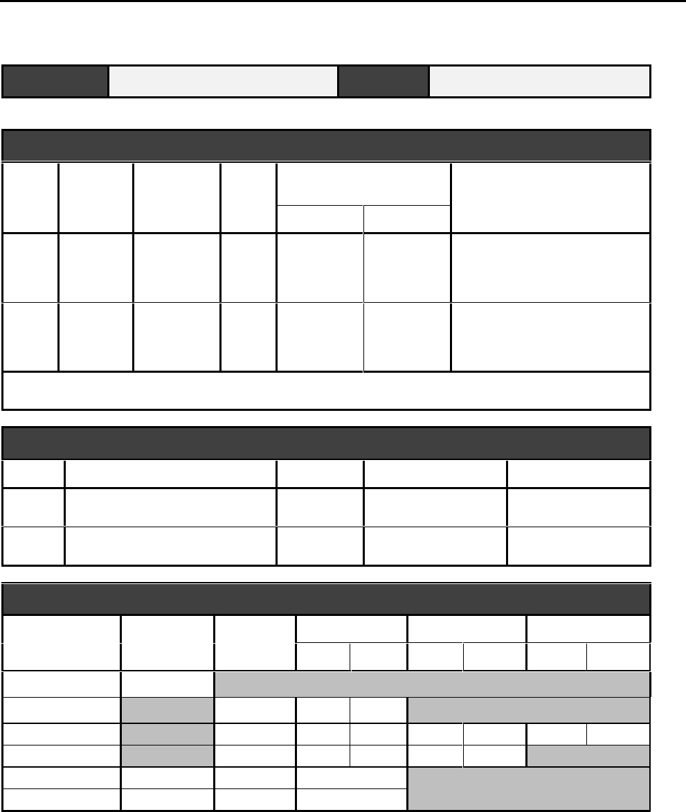
Interactive Technologies, Inc. © 1998 351 Installation and Reference Manual
106
351 Installation Planning Form
APM NAME LOCATION
OPTIONS
Output Denied
Access Security
System Panic Wireless Point Control Occupancy Monitoring
Arm/Disarm Lights Star
2
❑ Door 1
❑ Door 2
❑❑❑ ❑❑ Door 1 ❑ Door 2
Maximum: ________
Current: ________
❑ Disable Reader
4
❑ Door 1
❑ Door 2
❑❑❑ ❑❑ Door 1 ❑ Door 2
Maximum: ________
Current: ________
❑ Disable Reader
Note: If “Panic” is selected, choose the initial-on time (minimum): ________ seconds
the time-out (minimum): ________ seconds
READERS AND KEYPADS
Reader Description Keypad Type
LED Type
1
❑ Yes
❑ No
❑ Wiegand
❑ Magnetic Stripe
❑ Red Only
❑ Red/Green
2
❑ Yes
❑ No
❑ Wiegand
❑ Magnetic Stripe
❑ Red Only
❑ Red/Green
MAGNETIC STRIPE CARD DATA FORMAT
Field Character Digits Position 1 Position 2 Position 3
Start End Start End Start End
Start Sentinel
Site Code
Card Number
ID Number
Separator
End Sentinel

Interactive Technologies, Inc. © 1998 351 Installation and Reference Manual
107
351 Installation Planning Form
APM NAME LOCATION
SYSTEM POWER
Power Supply Circuit Breaker Backup Battery
Voltage Location Number Location
❑ Yes ❑ No
ADD-ON OPTION KITS
❑ Keypad ❑ Battery Backup Kit

Interactive Technologies, Inc. © 1998 351 Installation and Reference Manual
108
12. Appendix C: 351 Schedules Planning Form
This appendix contains a master copy of the 351 Schedules Planning Form. Use this form to
document your APM settings and options. Detailed instructions for completing this form are in
Section 3, Installation Planning.

Interactive Technologies, Inc. © 1998 351 Installation and Reference Manual
109
351 Schedules Planning Form
APM NAME LOCATION
ACCESS SCHEDULES
Schedule Zone Interval 1 Interval 2 Days
Start
Time End
Time Start
Time End
Time (1)
Mon.
(2)
Tues.
(3)
Wed.
(4)
Thur.
(5)
Fri.
(6)
Sat.
(7)
Sun.
(8)
Hol.
A0___:___ ___:___ ___:___ ___:___ ❑
❑
❑
❑
❑❑ ❑ ❑
1___:___ ___:___ ___:___ ___:___ ❑
❑
❑
❑
❑❑ ❑ ❑
2___:___ ___:___ ___:___ ___:___ ❑
❑
❑
❑
❑❑ ❑ ❑
3___:___ ___:___ ___:___ ___:___ ❑
❑
❑
❑
❑❑ ❑ ❑
B0___:___ ___:___ ___:___ ___:___ ❑
❑
❑
❑
❑❑ ❑ ❑
1___:___ ___:___ ___:___ ___:___ ❑
❑
❑
❑
❑❑ ❑ ❑
2___:___ ___:___ ___:___ ___:___ ❑
❑
❑
❑
❑❑ ❑ ❑
3___:___ ___:___ ___:___ ___:___ ❑
❑
❑
❑
❑❑ ❑ ❑
C0___:___ ___:___ ___:___ ___:___ ❑
❑
❑
❑
❑❑ ❑ ❑
1___:___ ___:___ ___:___ ___:___ ❑
❑
❑
❑
❑❑ ❑ ❑
2___:___ ___:___ ___:___ ___:___ ❑
❑
❑
❑
❑❑ ❑ ❑
3___:___ ___:___ ___:___ ___:___ ❑
❑
❑
❑
❑❑ ❑ ❑
D0___:___ ___:___ ___:___ ___:___ ❑
❑
❑
❑
❑❑ ❑ ❑
1___:___ ___:___ ___:___ ___:___ ❑
❑
❑
❑
❑❑ ❑ ❑
2___:___ ___:___ ___:___ ___:___ ❑
❑
❑
❑
❑❑ ❑ ❑
3___:___ ___:___ ___:___ ___:___ ❑
❑
❑
❑
❑❑ ❑ ❑
X00:00 23:59 (always) ■■
■■
■■
■■
■■■■■■■■
Y00:00 00:00 (never) ❑
❑
❑
❑
❑❑ ❑ ❑

Interactive Technologies, Inc. © 1998 351 Installation and Reference Manual
110
351 Schedules Planning Form
APM NAME LOCATION
HOLIDAYS
Holiday Description Type Start Date
Start Time
End Date End Time
1❑ Fixed ❑ Variable ___/___/___
___:___
___/___/___ ___:___
2❑ Fixed ❑ Variable ___/___/___
___:___
___/___/___ ___:___
3❑ Fixed ❑ Variable ___/___/___
___:___
___/___/___ ___:___
4❑ Fixed ❑ Variable ___/___/___
___:___
___/___/___ ___:___
5❑ Fixed ❑ Variable ___/___/___
___:___
___/___/___ ___:___
6❑ Fixed ❑ Variable ___/___/___
___:___
___/___/___ ___:___
7❑ Fixed ❑ Variable ___/___/___
___:___
___/___/___ ___:___
8❑ Fixed ❑ Variable ___/___/___
___:___
___/___/___ ___:___
9❑ Fixed ❑ Variable ___/___/___
___:___
___/___/___ ___:___
10 ❑ Fixed ❑ Variable ___/___/___
___:___
___/___/___ ___:___
DAYLIGHT SAVINGS TIME CHANGES
Time
Change Description Date Old Time New Time
1 ___ / ___ ___:___ ___:___
2 ___ / ___ ___:___ ___:___

Interactive Technologies, Inc. © 1998 351 Installation and Reference Manual
111
13. Appendix D: 351 Database Planning Form
This appendix contains a master copy of the 351 Database Planning Form. Use copies of this
form to plan your APM database. For more information, see the “DBASE Command” in Section
7, Programming Your 351.

Interactive Technologies, Inc. © 1998 351 Installation and Reference Manual
112
351 Database Planning Form
APM NAME LOCATION
MASTER LEARN / DELETE CARDS
Card Name Card # Schedule Category Privileges
Door 1 Door 2 System
Arm/Disarm Wireless Point
Control
A
B
C
D
E
[Delete]
ACCESS DATABASE
Name Card # PIN Schedule Category Privileges
Door 1 Door 2 System
Arm/Disarm Wireless Point
Control

Interactive Technologies, Inc. © 1998 351 Installation and Reference Manual
113
351 Database Planning Form
ACCESS DATABASE
Name Card # PIN Schedule Category Privileges
Door 1 Door 2
System
Arm/Disarm
Wireless Point
Control

Interactive Technologies, Inc. © 1998 351 Installation and Reference Manual
114
14. Appendix E: APM Error Messages
There are three types of error messages:
• command error messages
• event error messages
• communication (Net Error) messages
The most common error messages are command and event error messages. All of these error
messages are described in this appendix.
14.1. APM Command Error Messages
Command error messages are produced by your APM in response to something you type. Below,
all such error messages are listed, along with probable reasons for the messages:
BAD COMMAND You entered a command that your APM did not recognize.
Misspelling the command is usually the cause of this
message.
FORMAT ERROR You used illegal values while using the “unprompted”
command entry (or command line).
Examples: entering letters for a numeric field or entering a
nine-digit site code.
FORMAT ERROR
R-retry The last parameter you entered contains illegal values
Example: such as letters when only numbers are allowed.
Pressing the R key allows the parameter to be entered
again.
ID EXISTS You attempted to add an ID (such as a card or PIN) that
already exists in the APM database.
ID TOO LARGE You attempted to add an ID to the APM database, but that
number that is too large for the card format used.
ILLEGAL DEFAULTS There were illegal default values set in one (or more) of the
parameters you just tried.
Examples: A [Rtn] was entered in response to a prompt,
default values (or combination of default values) are not
appropriate for the command; you tried to use the DBASE
add command with default PIN and card number.
INVALID The command you entered is correct, but is parameters are
not consistent with the APM’s current configuration.
INVALID PSW You entered a password that doesn’t match the password
programmed into the APM.
MEMORY FULL Your cardholder database memory is completely full.
NAME EXISTS You attempted to add an APM name that already exists.

Interactive Technologies, Inc. © 1998 351 Installation and Reference Manual
115
NOT FOUND You requested the APM to do something with piece of data
(a PIN, card number, or name) that wasn’t found in the
database.
PLEASE LOGON You must log into the APM before any command (except
LOGON and LOGOFF) can be executed.
This message indicates that either the LOGON command was
not executed or that 2 minutes passed without any
commands being entered, so your APM logged off
automatically.
PSW MISMATCH When you change a password, the new password must be
entered twice. This message indicates that the second
password entry did not match the first.
TABLE FULL You attempted to add a holiday or DLS entry, but the table
is already full.
Only 10 entries are in the holiday table and only 2 entries
are in the DLS table.
UNABLE TO
COMPLETE COMMAND The command you entered didn’t work. Perhaps, the
network failed or is busy delivering higher priority
messages.
14.2. Event Error Message
Event error messages are produced by your APM in response to external events. Below, all such
error messages are listed, along with probable reasons for the messages:
ERROR-CARD Someone presented a card that is not in the APM database.
ERROR-MASK Someone presented a card, but its format doesn’t match the
format programmed into the APM.
Examples: A data error is being read from the card, bad
data might be sent from the reader to the, or the card is not
compatible with your present APM configuration. In
Wiegand mode, the number of bits read from the card may
be incorrect. In magnetic-stripe mode, the number of digits
read from the card was incorrect or defined constant(s)
were not found.
ERROR-PARITY A data error was detected on data sent from a reader to your
APM.
Example: In magnetic-stripe mode, this indicates a parity
error on one (or more) digits or an LRC (Longitudinal
Redundancy Check) error on data received.
ERROR-PIN Someone used a card at the reader or typed at the keypad,
but the PIN that is entered is not in your APM database.

Interactive Technologies, Inc. © 1998 351 Installation and Reference Manual
116
ERROR-SC Someone used a card at the reader, but its site code doesn’t
match the APM site code.
ERROR-SEC Someone tried to enter the building when the security
system was armed.
ERROR-TMP Someone tried to use an expired, temporary token (a card
or PIN).
Examples: the token’s valid time interval has expired, the
number of uses has been exhausted, or both.
ERROR-TS Someone tried a token (such as a card or PIN), but didn’t
have access privileges for that time.
14.3. The Net Error Message
The NET ERROR message appears is an internal communication error from your APM. Below,
all such error messages are listed, along with probable reasons for the messages.
A Net Error Message has five parts:
• the error code,
• source APM address,
• source point address,
• destination APM address, and
• destination point address.
An example examples of a net error message is shown below:
04/09/97 TU 9:43 LOBBY NET ERROR #111 src=266,10 dst=266,10*
This means that at 9:43 on April 9th, 1997, an error code 111 occurred where the source APM
was AP266, the destination APM was AP366, and both source and destination point addresses
were 10.
An APM address is a unique identifying number that is encoded in the software.
Note: A point address is useful primarily to ITI Technical Services and not the user.
Net error codes can be divided into three categories:
• Transmit-Side Codes,
• Receive-Side Codes, and
• Operating System Codes.
14.3.1. Receive-Side Net Errors
Receive-Side Net errors mean that an APM received an incomplete message, no messages, or a
message from an unexpected source. These codes are listed below:
102, 104, 106, 108, 110, 112, 113, 114, 120, 140, 141, 142

Interactive Technologies, Inc. © 1998 351 Installation and Reference Manual
117
14.3.2. Transmit-Side Net Errors
Transmit-Side Net errors mean that an APM couldn’t send a complete message, or the final
destination didn’t acknowledge it received the message, often due to APM failure. These codes
are listed below:
100, 101, 105, 107, 111, 117
14.3.3. Operating System Net Errors
Operating System Net errors happen when your APM runs out of memory or is overloaded. These
codes are listed below:
91, 92, 93, 145, 150, 151, 153, 154, 155, 156, 157
Note: Most of these net errors never occur. However, it is normal to see some net errors while
powering up or powering down an APM.
14.4. When Might Net Errors Appear?
14.4.1. Startup Errors
If your APM is being powered up, such as after a power failure, you might see a few net errors:
100, 103, or 111.
14.4.2. Shutdown Errors
If an APM fails, you might see a few error messages:
100, 110, 111, or 112
Also, your
sba
and
sbd
tallies, listed on the Full Report, might reflect six APM communication
attempts.

Interactive Technologies, Inc. © 1998 351 Installation and Reference Manual
118
15. Appendix F: Glossary of APM Terms
351
The model number of an ITI Access Point Manager. This ITI product is a card-access, -point
monitoring, and device-control processor for buildings, rooms, parking lots, etc. The terms
“APM” and “351” are used interchangeably.
access mode
A mode of operation in which an input cannot generate an alarm condition, or when an access
point allows unrestricted access. Points can be put in this mode by using time schedules. (The
other mode of operation is the secure mode.)
Access Point Manager (APM)
See “351.”
Alarm Arm / Disarm
See “Security System Arm / Disarm.”
APM (Access Point Manager)
See “351.”
card reader
See “reader.”
category
A grouping of cardholders in your APM database used for assigning time schedules and printing
reports.
denied access indicator
A door access option that energizes an output when an invalid card/PIN is presented at the reader/
keypad. The output can activate an external annunciator, a camera, or other external circuitry
specific to your system
door ajar time
The number of seconds, after the door strike time expires, when a door can be open without
causing the “door open” alarm.
door position sensor
A device wired to a door that monitors whether the door is open or closed.
door strike
A type of lock that can be locked or unlocked by electronic switching.
door strike contact
The normal status of the door lock mechanism: normally open (NO) or normally closed (NC).
Interactive Technologies, Inc. © 1998 351 Installation and Reference Manual
119
door strike time
The number of seconds that a door remains unlocked with a valid entry.
door strike type
An access setting that identifies which of three types of strikes is being used on the doors: fixed,
memory, or non-memory
electronics module
A removable and replaceable board in the 351, which contains all necessary electronic
components.
employee category
See “category.”
holiday schedule
A group of up to 10 days during the calendar year, when the time schedule differs from the
regular schedule. For example, if New Year’s falls during the week, access to the facility might
be handled like it is a weekend, rather than a regular weekday.
inputs
The separate channels through which your APM receives external information.
interlock
Connecting one or more inputs to one dedicated output. When interlocked inputs are in the alarm
or trouble state, the interlocked output is activated.
learn function
An option that allows cards to be added or deleted from the database when using special cards at
the reader.
LED
Light-emitting display.
lockout
An option that allows the operator to disable a reader. When in this mode the reader indicator
lights are shut off, access requests are ignored, and no access events are logged.
map
See “interlock.”
memory capacity
The amount of random access memory (RAM) in the 351. The memory capacity for your APM is
32,768 bytes.
non supervised
An input that is wired without an end-of-line resistor. These points can assume two states: normal
and alarm.
Interactive Technologies, Inc. © 1998 351 Installation and Reference Manual
120
occupancy monitoring
An option that monitors and controls occupancy within a secured area.
outputs
The separate channels through which your APM controls external devices.
output device
An electronic device that is attached to one of your outputs and responds to events at the entrance,
based on the specific configuration rules.
personal identification number (PIN)
A number given to an individual for use with a keypad to access something that is APM
controlled. A PIN is often used with a card.
presented
This term describes how you trip the reader with your toke. This term describes differing actions
with the each token used: for a card you slide or swipe it through the reader, for a PIN you type it
at the reader, for a proximity card you place it near the reader, for a keychain transmitter or panic
you press the appropriate buttons near the reader.
RAM
Random Access Memory. See also “memory capacity.”
reader
A device that detects and reads the unique token, often a card, required for access. The reader
transmits the token data to the APM.
RS-232
A standard communications interface used between your APM and the terminal.
secure mode
A way of operating so that inputs can generate alarms. Points are put in this mode by using time
schedules. (The other mode of operation is the access mode.)
Security System Arm / Disarm
A database option that allows a security system to be armed with a time schedule and be armed or
disarmed with certain cards used at the reader.
supervised
An input that detects tampering with an end-of-line resistor. These points can assume three states:
normal, alarm, or trouble.
terminal
Any device, linked to your APM via an RS-232 communications interface, that is used to either
program your APM or display data from it.
time interval
A time period defined by an inclusive start time and an inclusive stop time.

Interactive Technologies, Inc. © 1998 351 Installation and Reference Manual
121
TIME SCHEDULES:
A 00:00-07:59 --:-- --:-- MO,TU,WE,TH,FR,SA,SU
23:45-23:59 08:00-08:14 MO,TU,WE,TH,FR,SA,SU
--:-- --:-- --:-- --:--
--:-- --:-- --:-- --:--
9148G 11A .D S F
ONE TIM E INTERVAL
time schedules
An option that includes up to four user-definable access time ranges, as well as Always and Never
fixed-time ranges. A time schedule is active if the current time and date fall within its time zones.
TIME SCHEDULES:
A 00:00-07:59 --:-- --:-- MO,TU,WE,TH,FR,SA,SU
23:45-23:59 08:00-08:14 MO,TU,WE,TH,FR,SA,SU
--:-- --:-- --:-- --:--
--:-- --:-- --:-- --:--
9148G 12A .D S F
ONE TIM E SCHEDULE

Interactive Technologies, Inc. © 1998 351 Installation and Reference Manual
122
time zone
One of the four time periods a time schedule can be divided into; the period during the day when a
time schedule is active. They are associated with days of the week and control inputs, outputs, and
access.
TIME SCHEDULES:
A 00:00-07:59 --:-- --:-- MO,TU,WE,TH,FR,SA,SU
23:45-23:59 08:00-08:14 MO,TU,WE,TH,FR,SA,SU
--:-- --:-- --:-- --:--
--:-- --:-- --:-- --:--
9148G 10A .D S F
ONE TIME ZONE
toggle
To alternate your display to show available options or to flip from one thing to another, such as
“toggling off and on.”
token
A unique ID stored in your database and recognized by your APM to grant entry or exit. A token
can be a PIN, a card, or both.
trouble state
See “supervised.”

Interactive Technologies, Inc. © 1998 351 Installation and Reference Manual
123
Index
2
24-hour format, 67
3
351
defined, 119
troubleshooting, 92, 97
351 Database Planning Form, 13, 112
351 Installation Planning Form, 13,
105
351 Schedules Planning Form, 13,
109
A
ABORTED message, 51
AC power
connect terminals to, 43
diagram, 43
for APM, 24
for contacts, 44
for electronics module, 42
for relays, 20
input power, 104
plugging in, 49
troubleshooting, 97
wiring, 42
access
ajar times, 72
alarms with valid entry, 72
denying, 24, 33, 77
devices for remote, 76
door options, 119
events, 60
example, 17
holiday schedules, 120
LED responses, 23
Occupancy Monitoring Option, 76
planning for, 35
preventing, 16, 53, 83
privileges, 117
schedules, 17, 25
settings, 53, 120
strike times, 72
time zones, 123
times, 17, 67
token, 35
troubleshooting, 103
using PINs, 84
access attempts
detecting, 23
outputs and, 21, 78
access cards, 80
access control, 15-17, 32, 84
access mode, 119, 121
access point, 119
access schedules, 16
access timer, 96
access times, 122
accessing information, 52
active
initial on-times, 21, 76
outputs, 20, 21, 30, 73, 78
panics, 78
relays, 20
time intervals, 26, 71
time schedules, 20, 69, 96, 122, 123
time zones, 69
troubleshooting outputs, 96, 102
active state, 20
adding
cards, 85, 91
cards with DBASE, 85
Daylight Savings Times, 71
door settings, 72
groups of cards, 86
holidays, 68
Master Learn / Delete Cards, 53, 90
PINs, 85
time schedules, 70
addresses
APM, 117
destination points, 117
source points, 117
ajar time
0-second, 72
default, 72
defined, 18, 72
Full Report, 59
retaining APM values, 72
alarm
access modes, 119
caused by ajar times, 72
conditions on Event Report, 60
door open, 119
events, 73
point monitoring, 14
status, 57
troubleshooting, 101, 102
with valid access, 72
alarm messages
examples, 92
ignoring, 17, 73
alarm state
example, 21, 92
interlocked outputs, 21, 120
mapped inputs, 21
normally open, 19
open circuit, 19
troubleshooting, 96, 101, 102
types of, 19, 121, 122
Alarm System Arm / Disarm. See
Arm / Disarm
alarms
device types, 38
Always Time Schedules, 17
APM
accessing information on, 52
applying power, 48
avoiding wiring problems, 40
configuration, 55
definition, 119
devices, 66
dimensions, 104
factory set name, 66
mounting, 38, 39
name, 66
options, 20
overview, 15
password, 24, 52
planning, 25
power, 24
prepower checklist, 48
programming commands, 66
schedule commands, 52
scrolling through display, 54, 60,
64, 65
settings, 55
site code, 52
specifications, 13
storage capacity, 22
system status, 23
testing, 92
total power, 24
troubleshooting, 12, 92, 97
weight, 104
wiring, 38, 41, 42
APM command, 52, 66
Arm / Disarm Option, 21-23, 36, 59,
75, 76, 119, 121
ARM/DIS. See Arm / Disarm Option
cardholder, 85
attributes
categories, 62
of categories, 61
audience. See User & Installer
automatic
assigned category, 85, 86
log off, 53
time changes, 71
B
backup
battery kit, 38

Interactive Technologies, Inc. © 1998 351 Installation and Reference Manual
124
power, 92
BAD COMMAND message, 50, 115
Badge Reports
command reference, 64, 65
examples, 64
bar code, 31
bar code readers, 18
basic setup commands, 66
battery
backup kit, 24
caution, 42
charger, 49
connecting, 49
load, 49
planning, 35
status, 50, 57
testing, 96
troubleshooting, 98
warning, 42
wiring, 49
BATTERY OK message, 96
baud rate, 32, 42, 46, 104
Belden cable
9535, 47
9553, 47
C
cable
3-conductor type, 38
connecting to terminal, 46
for power source, 49
grounding shielded type, 40
maximum length, 46
separate for strikes, 48
stripping guidelines, 40
troubleshooting, 97, 99
type for terminal, 38
wiring guidelines, 40
capacity
buffer, 104
database, 104
memory, defined, 121
card E. See Master Learn Delete
Cards
CARD ERROR messages, 116
card format. See also SETMAG
command
card numbers, 32-35
Cardholder Report, 61
defined, 62, 84
for groups of cards, 85
magnetic stripe, 86
troubleshooting, 103
Wiegand, 86
card readers, 119. See readers
cardholder
access, 16
attributes, 22, 62, 84
category, 62
identification numbers, 84
information, 53, 55
names, 22, 35, 62, 84, 88
numbers stored in database, 22
planning, 35
planning info, 35
time schedules, 84
using card and PIN, 85
Cardholder Database. See also
database
attributes, 62
capacity, 104
maintaining, 51, 84
programming, 66
setting up, 84
Cardholder Reports, 55, 61
cards
access, 14, 53, 119
adding, 85, 86, 89
as tokens, 123
data placement variations, 80
deleting, 88, 89
disarming with, 21
errors, 117
format, 33
invalid, 119
learning states, 23
magnetic stripe format, 24, 32
Master Learn / Delete Cards, 60
modifying, 87
PINs, 121
presenting, 16, 121
requiring PINs, 103
setting unique features, 87
site codes, 24, 32
test cards, 94
token type, 35
troubleshooting, 100, 101, 103, 115-
117
type of ID, 22
using with PIN, 85
Wiegand, 31
category
attributes, 62
automatically assigned, 85, 86
definition, 119
deleting by, 89
displayed on Cardholder Report, 61
example, 84
for cardholders, 22, 85
for cards, 87
for groups of cards, 85
Full Report, 60
of cardholders, 35
of Net Error messages, 117
wild card, 61
Category Report
Badge Reports, 64
command reference, 61
defined, 61
displaying, 61
Event Report, 60
examples, 62, 63
Name Reports, 65
verifying card data, 88
caution
backup battery, 42
DC power, 43
defined, 14
external devices, 44
OPT command, 75
passwords, 79
powering APM, 48
CCTV, 38
changing
APM password, 52
cards, 87
date, 67
Daylight Savings Time, 52
holidays, 68
outputs, 82
passwords, 79, 80
PINs, 87
time schedules, 69
checklist, 38, 48
circuit breaker, 35
circuits
closed, 19
open, 19
short, 19
closed state, 19
codes
bar codes, 18, 31
default for site, 80
for error messages, 117
for Net Error messages, 117
National Electrical, 42
Operating System Net Errors, 118
Receive-Side, 117
shutdown errors, 118
site, 24, 80
startup errors, 118
Transmit-Side Net Errors, 118
command entry mode, 52, 54
command error messages, 115
commanding outputs, 82
commands
aborting, 51
APM, 66
Badge Reports, 64
Category Reports, 55, 61
complete list of, 54
database type, 85
DATE, 66
DBASE, 73
described, 52
DLS, 71
DOOR, 72, 103
entry mode, 52
error messages, 115
functions of, 52
hardware type, 72
HELP, 54

Interactive Technologies, Inc. © 1998 351 Installation and Reference Manual
125
HOL, 68
how to enter, 54
incorrectly entered, 51
IO, 101, 102
LEARN, 90
list of references, 9
LOCK, 83
LOGOFF, 54
LOGON, 53, 116
Master Card type, 90
programming, 66
PSW, 53, 79
RDR, 98-101
ready to receive, 51
REL, 82, 96
REP, 55, 88
responses, 51
SC, 80
schedule type, 68
SETMAG, 33, 80, 94, 100
setup type, 66, 79
TIME, 67
troubleshooting, 99, 115, 116
TS, 69
type of error message, 13, 115
common
error messages, 115
point, 20
communications
messages, 115
Net Error message, 117
suggestions for testing, 92
testing, 50
troubleshooting, 100
with APM, 32
computer, 46
configurations, 55, 66
APM, 51, 55
input, 19
printing, 52
program, 46
terminal settings, 47
troubleshooting, 102, 115, 116
configuring, terminals, 46, 47
connections
input terminals, 48
terminals, 44
contact
door strike type, 120
rating, 104
troubleshooting, 101, 102
types of, 28, 29, 57, 73
control
commands, 82
devices, 66
crash bar, 18
current
date, 52
time, 52
D
data
checks, 32
defining, 80
displayed, 14, 122
fields, 32
troubleshooting, 116
data errors, 116
data format
defining, 33
magnetic stripe, 32, 34, 81
planning example, 34
database
access times, 17
adding
at reader, 36
cards to, 22
groups of cards, 85, 86
individual cards and PINs, 85
Master Learn / Delete Cards, 90
attributes, 62
backup and restore software, 38
capacity, 104
commands, 85
deleting from, 36, 88, 89, 91
full message, 60
information stored in, 84
installing software, 47
learn function, 120
maintaining, 51, 66, 84
memory, 60
modifying groups of cards, 85
options, 121
planning, 35
programming, 66
searching for entries, 61
setting up, 12, 25, 84
storage capacity, 22
tokens, 123
troubleshooting, 103, 115, 116
Database Planning Form, 13, 112-114
date. See also DATE command
changing, 67
current, 17, 66, 67
displaying, 67
event logging and, 67
of access attempt, 16
of holidays, 25
setting current, 52, 66
start and end, 68
DATE command, 52, 66, 67
Daylight Savings Time. See also DLS
command
adding dates, 71
changing, 27, 52
deleting dates, 71
explained, 17, 71
Full Report, 58
planning, 27
standard, 71
DBASE command
adding PINs or cards, 86, 87
changing cards an PINs, 87
deleting with, 89
modifying, 88
DC power
caution, 43
diodes, 48
for contacts, 44
for electronics module, 42
for relays, 20
plugging in, 49
power supply, 43
specifications, 24, 104
total for APM, 24
troubleshooting, 97
wiring, 43, 44
dead-bolt locks, 18
defaults
ajar times, 72
Arm / Disarm, 90
category letters, 90
door names, 77
door to inputs, 73
for inputs, 73
illegal values, 115
initial on-time, 78
input names, 73
magnetic stripe format, 33
names, 57, 73
output names, 58, 93
password, 53, 79
site code, 80
strike time, 72
time schedules, 73
troubleshooting, 115
Wireless Point Control, 90
defining
card format, 33
door strike settings, 52
inputs, 52, 74
magnetic stripe format, 80
outputs, 52, 73
reader settings, 78, 79
SC, 80
SETMAG, 80
time schedules, 69
definitions
351, 119
access mode, 119
APM, 14
Arm / Disarm, 119, 121
category, 119
denied access indicator, 119
door ajar time, 119
door position sensor, 119
door strike, 119
door strike contact, 120
door strike time, 120
door strike type, 120
duration, 21

Interactive Technologies, Inc. © 1998 351 Installation and Reference Manual
126
electronics module, 120
events, 23
holiday schedule, 120
holidays, 25
inputs, 120
interlock, 120
learn function, 120
LED reader, 120
lockout, 120
memory capacity, 120, 121
non-supervised, 121
occupancy monitoring, 121
output device, 121
outputs, 121
PIN, 121
RAM, 121
reader, 121
RS-232, 121
secure mode, 121
supervised, 122
terminals, 14, 122
time intervals, 122
time schedules, 122
time zone, 123
toggle, 123
token, 123
trouble state, 123
deleting
cards, 88, 89, 91
Daylight Savings Times, 71
holidays, 69
Master Learn / Delete Cards, 53
PINs, 88
denied access
indicator, 119
state, 23
Denied Access Option, 20, 31, 59, 75
devices
associated with outputs, 20
caution, 44
control processor, 14
controlling, 51, 119
Denied Access Option and, 75
door strikes, 18
entrance & exit, 18
inputs, 29
Interlock, 21
linked to APM, 14
maintaining, 66
mounting, 38
outputs, 121
programming, 66
readers, 121
sensors, 119
terminal connections, 44
total power, 24
types of, 18
verifying states of, 93
diagram
access control, 15
alarm monitoring, 16
magnetic strike, 45
mounting dimensions, 39
normally open strike, 45
wiring, 41, 43
dimensions, 39, 104
diodes, 44, 48
DIP switches
configuring terminal, 46
setting, 46
terminal set up, 46
Disarm/Arm Option, 21
display
scrolling through, 60, 64, 65
terminal alarm messages, 92
terminal error messages, 100, 101
terminal messages, 94, 95, 102
toggling through, 123
displaying
category report, 61
current time, 67
date, 66, 67
event logs, 23
Event Report, 60
Full Report information, 55, 57, 58
keyboard settings, 58
Name Reports, 65
power, 57
reader settings, 58
settings, 58
time, 67
distances for cables, 47
DLS. See also Daylight Savings Time
changing, 71
DLS command, 52, 71
troubleshooting, 116
door 1
diagram, 45
sensors, 48
time schedules, 87, 90
door 2
diagram, 45
sensors, 48
terminal connections, 44
time schedules, 86, 87, 90
DOOR command, 52, 72, 103
door open alarm, 119
door position sensors, 20, 38, 48, 119
Door Secure State, 23
door strikes
0-second ajar time and, 72
contact, 120
defining, 18, 52, 119
example, 29
normally open, 28
outputs and, 44
outputs for, 20
planning, 28, 29, 38
settings, 72
strike time and, 72
terminal connections, 44
times, 72, 96, 120
types, 28, 120
wiring, 44, 48
doors. See also DOOR command
access options, 119
ajar times, 72, 119
contact type, 74
controlling entrances, 18
default names, 77
defining strikes, 52
Denied Access Option, 20, 75
disarming system at, 21, 76
fixed time, 18
lock types, 18
mounting readers, 39
names of, 77
Occupancy Monitoring Option, 22,
75
outputs, 31
peripherals, 38
planning, 28, 35
quantity supported, 20
required reader, 47
settings, 59, 72
special functions, 18
strike times, 18, 72
troubleshooting, 103
unlocking, 18
duration, 21
E
earth grounding, 42
egress. See also exit
defined, 20
inputs, 74
occupancy monitoring, 76
planning, 29
electronics module
definition, 120
powering, 42
troubleshooting, 97-103
end of line resistors, 48
entering
cardholder info, 53
command entry mode, 52
door settings, 72
time schedules, 52
entrance / exit
devices, 18
troubleshooting, 99
equipment
checklist for, 38
unrelated to APM, 40
error messages
APM failure, 118
command error, 115
common, 115
communication type, 115
event error, 115
event type, 116
incorrect command, 51

Interactive Technologies, Inc. © 1998 351 Installation and Reference Manual
127
MASK ERROR, 100
net error, 115, 117
parity, 116
PARITY ERROR, 101
types of, 115
event error messages, 116
event log, 23
Event Report
command reference, 60
defined, 23, 55
displaying, 60
example of, 61
memory, 60
events
definition, 23
effects of date, 67
error messages, 13, 115
logging, 67
on reports, 60
storage capacity, 104
examples
24-hour time, 67, 68
alarm message, 92
alarm state, 92
Arm / Disarm Option, 21
Badge Reports, 64
baud rate planning, 32
card data format, 34
card number planning, 36
category, 84
category planning, 36
Category Reports, 62, 63
database planning, 36
door strikes, 29
end character, 81
Event Report, 61
field separators, 81
FORMAT ERROR message, 115
Full Report, 57
group name, 86
holiday schedules, 120
holidays, 16, 26
inclusive times, 71
interlocking, 75
keypad planning, 32
list of, 11
magnetic stripe format, 81, 116
Master Learn / Delete Card
planning, 37
mm/dd/yy, 68
name planning, 36
Name Reports, 65
Net Error message, 117
normal message, 92
normal state, 92
on state, 93
option planning, 31
output planning, 30
PIN, 36, 95
PIN ERROR message, 95
planning
add-on options, 28
inputs, 30
time changes, 28
time schedules, 27
privileges planning, 36
reader planning, 32
separator character, 81
SETMAG command, 81
site code, 32
strikes, 44
system power planning, 35
test PIN name, 95
time change planning, 27
time intervals, 71, 122
time schedules, 17, 21, 27, 68, 69,
122
time zones, 123
trouble message, 93
valid entry message, 94, 95
Wireless Point Control Option, 22
exit. See egress
command entry mode, 52
occupancy monitoring, 76
troubleshooting, 99
exit / entrance devices, 18
exit buttons, 48
exit switch kits, 38
external devices, 24, 44
F
factory set name, 66
fail secure, 28
fail unsecure, 28
figures
access control, 15
alarm monitoring, 16
list of, 7
fixed
holidays, 17, 25, 58, 68
settings on Full Report, 59
strike type, 72
fixed resistors, 19, 73
fixed time, 18, 122
Form C contacts, 44
FORMAT ERROR message, 115
formats
24-hour, 67
hh:mm, 68
magnetic stripe, 24
mm/dd/yy, 66
output planning, 31
setting for reader, 52
Wiegand, 79
forms
351 Database Planning Form, 112
351 Installation Planning Form, 105
351 Schedules Planning Form, 109
Full Reports, 55
command reference, 55
described, 55
displaying
information, 57
inputs, 57
output settings, 58
settings, 55
example of, 57
explained, 55
outputs, 58
printing, 50
sba and sbd tallies, 118
verifying settings, 69
G
general-purpose
inputs, 19
outputs, 20, 44
glossary, 13
granting access states, 23
green and red LED, 23
ground loops, 40
grounding, 42, 43
groups
cards, 89
PINs, 89
searching for entries by, 61
guidelines
mounting, 39
password, 79
wiring, 40
H
hardware
planning, 28
setup, 25, 72
hardware commands, 52
HELP command, 52, 54
hexadecimal, 32
hh:mm format, 67-71
HOL command, 52, 68, 69
holiday intervals, 25
holiday schedules
defined, 120
renumbering of, 69
setting up, 52
holiday tables, 25
holidays. See also HOL command
adding, 68
defined, 16
deleting, 69
Full Report, 58
number, 16, 58
planning, 25
sequential numbers of, 69
types of, 17, 58
I
ID
as tokens, 123

Interactive Technologies, Inc. © 1998 351 Installation and Reference Manual
128
attributes, 22
for transmitters, 21
numbers, 21, 32, 34, 62
of all cards, 24
sent to receiver, 18, 22
stored in database, 22
troubleshooting, 115
ID EXISTS message, 115
ID TOO LARGE message, 115
IDS IN DBASE, 60
ignoring messages, 17
ILLEGAL DEFAULTS message, 115
inactive
outputs, 20, 21
state, 20
time-out duration, 21
inclusive times, 71
initial on-time, 21, 76, 78
input 1, 101
input 2, 29, 73
input 4, 29, 73
inputs
access modes, 119
changing settings, 73
configurations, 19
contacts, 48, 57
default time schedules, 73
defined, 52, 74, 120
devices, 29, 42
egress, 74
events reported, 23
Full Report, 57
general-purpose, 19
interlocked, 29, 96
IO command, 73
names of, 29, 57
nonsupervised, 57, 121
normal states, 92
normally closed, 19, 57
normally open, 19, 57
number of, 20, 77
planning, 29, 30
power, 24, 104
resistive types, 19
resistors and, 73
schedules, 20, 57
specifications, 104
state changes, 20
status, 57
supervision, 19, 29, 57, 92, 122
switches, 29
tamper, 19, 21
terminal connections, 48
testing, 92
time schedules, 52, 73
troubleshooting, 101, 102
unlocking doors with, 18
wiring, 48
installation planning, 12, 25
Installation Planning Form, 13, 105-
108
installing software, 47
INTACT message, 50
interlock. See also Interlock Option
definition, 120
example, 75
option, 75
troubleshooting, 101, 102
Interlocking Option, 21, 59, 75
intervals
holiday, 25
on Full Report, 58
time, 26
defined, 122
INVALID message, 115
INVALID PSW message, 115
IO command, 52, 73, 74, 101, 102
K
Keychain Transmitters, 21, 22
keypads
connecting, 42
Denied Access Option and, 75
descriptions, 31
displaying settings on Full Report,
58
LED, 95
locking and unlocking, 53, 83
mounting guidelines, 39
PINs, 121
planning, 32, 38
required, 47
testing, 92
troubleshooting, 98, 99, 103
used with readers, 31
using PINs on, 84
wiring, 47
kits
backup battery, 24, 28
exit switch, 38
keyboard option, 47
mounting specifications, 48
optional, 38
L
LEARN command, 53, 90, 91
learn function, 120
LED
defined, 31, 120
Full Report, 59
planning, 31
power indicator, 50
reader response, 23
state indications, 23
states, 23
testing, 94
troubleshooting, 97-99
LED, 97
types of, 23, 79
light-emitting diode. See LED
lists
commands, 54
of cardholders, 61
of command references, 9
of commands, 52
of examples, 11
of figures, 7
of required equipment, 38
of tables, 8
table of contents, 2
load, 49
LOCK command
explained, 53
readers, 83
locking
keypads, 53, 83
preventing access, 83
readers, 53, 83
status, 58
with LOCK command, 83
lockout, 120
locks
Caps Lock Button, 51
dead-bolt, 18
magnetic, 18
spring-bolt, 18
strike, 18
troubleshooting, 103
types of, 18
wiring, 44
logging off
automatically, 53
how to, 54
LOGOFF command, 52, 54, 116
LOGON command, 52-54, 116
logs, 23
longitudinal redundancy check. See
LRC
loops, ground, 40
LOST message, 50
LOW message, 50
LRC, 32
troubleshooting, 116
M
magnetic
locks, 18
strike, diagram, 45
stripe format, 79
magnetic strike
diagram, 45
magnetic stripe. See also SETMAG
command
card numbers, 86
default, 33
programming site codes for, 80
magnetic stripe format
errors, 116
explained, 18, 24, 32, 33
planning, 31, 34

Interactive Technologies, Inc. © 1998 351 Installation and Reference Manual
129
readers, 47, 52
SETMAG command and, 80, 81
site codes, 32
testing, 94
troubleshooting, 100, 116
magnetic stripe reader, 38
mag-stripe. See magnetic stripe
main electronics module, 42
maintaining
cardholder database, 12, 84
cardholder information, 53
database, 51, 66
optional settings, 15
mapped, 21
MASK ERROR message, 100, 116
Master Learn / Delete Cards
access and, 23
adding, 90, 91
deleting, 91
explained, 22, 90
LED response, 23
on Full Report, 60
planning, 36, 37
setting up, 53, 55
setting-up, 84
memory
capacity, definition, 120
cleared with power-up, 49
clearing, 79
errors associated with, 118
settings on Full Report, 59
strike door, 72
strike type, 18, 72
troubleshooting, 97, 115
memory capacity, definition, 121
MEMORY FULL message, 115
messages
ABORTED, 51
BAD COMMAND, 50, 115
BATTERY OK, 96
displayed on terminal, 50
error, 13, 51, 115
example of Net Error, 117
FORMAT ERROR, 115
ID EXISTS, 115
ID TOO LARGE, 115
ignoring, 17
ILLEGAL DEFAULTS, 115
INTACT, 50
INVALID, 115
INVALID PSW, 115
LOST, 50
LOW, 50
MASK ERROR, 116
MEMORY FULL, 115
NAME EXISTS, 115
Net Error, 117
NOT FOUND, 116
OK, 50, 51
PARITY ERROR, 116
PIN error, 95, 116
PLEASE LOGIN, 116
PRIMARY POWER FAILED, 96
PRIMARY POWER RESTORED,
50
PSW MISMATCH, 116
SC ERROR, 117
SEC, 117
TABLE FULL, 116
TMP ERROR, 117
troubleshooting, 99, 101, 102, 116
TS ERROR, 117
UNABLE TO COMPLETE
COMMAND, 116
valid entry, 94, 95
midnight, 71
mm/dd/yy format, 66-68
for variable holidays, 68
modes
access, 121
command entry, 53
entering command entry, 52
exiting command entry, 54
lockout, 120
secure, 121
troubleshooting, 100, 116
modifying
card, 87
PIN, 87
monitoring, 16
motion detector, 18
mounting
applying power, 48
dimensions, diagram, 39
equipment list, 38
guidelines, 39
overview, 12
the system, 39
N
NAME EXISTS message, 115
Name Report, 65
names
APM, 52, 66
attributes, 62
cardholder, 84
factory set for APM, 66
Full Report, 60
of cardholders, 22, 35, 84, 88
of doors, 72, 77
of inputs, 29, 57
of outputs, 30, 58, 82, 93
of points, 73, 74
of test PIN, 95
setting for APM, 66
troubleshooting, 115, 116
National Electrical Code, 42
NC. See normally closed. See
normally closed
Net Error messages
communication type, 115
example, 117
parts of, 117
types of codes, 117
Never Time Schedules, 17
NFPA No. 70, 42
NO. See normally open. See normally
open
non-memory, 18, 59
NON-SUP. See nonsupervised
non-supervised
definition, 121
inputs, 57
modes, 104
normal
access, 16
time schedules, 16
normal message, 92, 101
troubleshooting, 101
normal state
defined, 19
example, 92
explained, 19, 20, 82
inputs, 92, 93, 101, 102
troubleshooting, 101, 102
normally closed
contacts, 48, 73, 74, 104
explained, 20
how to short, 92
inputs, 19, 57
strike contact, 28
normally opened
contacts, 48, 73, 74, 104
diagram, 45
door contacts, 74
door strike, 28
explained, 19
how to short, 92
inputs, 19, 57
outputs, 20
relays, 20
NOT FOUND message, 116
numbers
ajar times, 72, 119
APM model, 119
deleting by, 88, 89
for site codes, 32
for strike times, 72
ID for transmitters, 21
IDs, 34
in site code, 34
maximum occupancy, 31, 76
names and, 88
of all cards, 24
of APM address, 117
of cardholders, 61, 76
of cards, 33 - 35, 84, 85, 87, 103
of circuit breakers, 35
of Daylight Savings, 58
of doors supported by APM, 20
of holidays, 16, 58, 69
of IDs, 21, 32

Interactive Technologies, Inc. © 1998 351 Installation and Reference Manual
130
of inputs, 20, 75, 77
of Master Learn / Delete Cards, 60,
90
of outputs, 20, 77
of PINs, 84, 121
of schedules, 17
of test cards, 94
of time schedules, 69
of time zones, 70
of weekdays, 69
on magnetic stripe, 24
passwords and, 79
sent with keypress, 22
site code, 94
strike time, 120
troubleshooting, 115 - 117
O
Occupancy Monitoring
definition, 121
Option, 22, 59, 76
Occupancy Monitoring Option, 31,
75, 76
off-state
outputs in, 93
troubleshooting, 102
OK message, 50, 51
on-line reference, 54
on-state, 93
on-time, 21, 59, 76, 78
open circuit, 19
alarm state, 19
open state, 19
operating system
codes, 117
net errors, 118
OPT command, 52, 75 - 77
optional
category letters, 84
kits, 38
names, 72
security measure, 80
SETMAG fields, 33
settings, 15
options
Arm / Disarm, 21, 23, 73, 76, 121
clearing, 75, 76
Denied Access, 20, 31, 75
described, 20
enabling, 77
for parking lots, 76
in current release, 75
Interlock, 21, 96
none, 59
occupancy monitoring, 22, 31, 76,
121
panic, 21, 31, 52, 76
planning, 31
privileges, 85
pulsing, 82
selecting, 52
settings, 59
Wireless Point Control, 76
output 1, 44, 94, 96
output 2, 31, 44, 73, 75, 76, 101, 102
output 3, 44, 96
output 4, 31, 44, 73, 75, 76, 102
output devices, 121
outputs
activating, 119
active, 21, 30, 73, 96
active with keypress, 21
associated doors, 31
changing settings, 73
commanded by transmitters, 22
commanding, 82
contacts, 44
controlled by transmitters, 22
default time schedules, 73
defined, 20, 52, 73, 121
devices, 17, 20, 38, 42
format planning, 31
formats, 31
general-purpose, 20, 44
in off-state, 93
inactive, 21
initial on-time, 21
interlocking, 21, 29, 75, 77, 120
IO command, 73
minimum duration for, 78
multiple options, 31
names, 30, 58, 82, 93
numbers of, 20, 77
occupancy monitoring, 22
on state, 93
operation of, 20
panic, 59, 78
passwords, 80
planning, 30
power, 24, 104
pulsing, 53, 82
resetting, 82
schedules, 58
settings, 58, 77
specifications, 104
states, 21, 58
terminal connections, 44
testing, 92, 93
time schedules, 20, 52
time-out duration, 21
troubleshooting, 102
turning off, 53, 82
turning on, 53, 82
types of, 30
why active?, 96
wiring, 44
overview, 15
P
panic, 59
initial on-time, 78
keypress, 21
outputs, 78
presenting, 121
settings, 78
signals, 21, 96
special functions, 18
PANIC command, 78
Panic Option, 21, 31, 52, 59, 75, 76,
78
PARITY ERROR message, 101, 116
Parking Lot Option, 75, 78. See also
Occupancy Monitoring Option
passwords. See also PSW command
caution, 79
changing, 52, 80
default, 53, 79
described, 24, 79
guidelines, 79
required, 53
troubleshooting, 115, 116
pendant panic transmitters, 21
peripherals
doors, 38
testing, 92
troubleshooting, 92
wiring, 42
Personal Identification Number. See
PIN
PIN
adding, 85
as tokens, 123
changing, 87
definition, 121
deleting, 88, 89
displayed on Cardholder Report, 61
errors, 117
invalid, 119
length of, 84
modifying, 87
planning, 35
presenting, 16, 121
requiring cards, 103
test PIN naming, 95
testing, 95
token type, 35
troubleshooting, 99, 103, 115 - 117
type of ID, 22
using, 84, 85
PIN ERROR message, 95, 116
planning
add-on options, 28
automatic time changes, 27
baud rate, 32
card numbers, 36
cardholder info, 35
Daylight Savings Time changes, 27
doors, 28
hardware, 28
holidays, 25
inputs, 29

Interactive Technologies, Inc. © 1998 351 Installation and Reference Manual
131
installation, 12, 25
LED type, 31
magnetic stripe format, 34
Master Learn / Delete Cards, 36
option kits, 28
outputs, 30
power, 35
readers, 31
schedules, 25
site code, 32
time intervals, 26
time schedules, 26, 27
time zones, 26
planning forms
Database, 13
Installation, 13
Schedule, 13
PLEASE LOGIN message, 116
point address, 117
point control
ID attributes, 22
point names, 73, 74
points
access, 119
changing names, 74
common, 20
inputs, 19
monitoring, 119
normally open, 20
outputs, 20
supervision, 74
troubleshooting, 102
wireless control of, 18, 22, 76
power
applying to APM, 24, 48, 49
backup, 24, 92
caution, 42, 48
changes, 60
checklist, 48
door access, 28
external devices, 44
failure, 118
Full Report, 57
input, 24
outputs, 20, 24
planning example, 35
source cable, 49
sources, 38
supply, 24, 35, 42
system, planning, 35
testing the back up, 96
total for APM, 24
transformer, 42
troubleshooting, 97, 98
power indicator, 50
power light, 49, 50
power supply
battery charger, 49
checklist, 38
damage to, 43
diagram, 43
diagrams, 43
plugging in, 49
wiring, 42
power up, 49
prepower checklist, 48
preventing access, 83
PRIMARY POWER FAILED
message, 96
PRIMARY POWER RESTORED
message, 50
primary power status, 57
printing
event logs, 23
reports, 50, 52
privileges
Arm / Disarm, 21, 22
attributes, 62
for groups of cards, 85
Full Report, 60
planning, 35, 36
wireless point control, 22
procedures, testing, 92
programming
control commands, 82
database commands, 85
introduction to, 51
Master Learn / Delete Cards
commands, 90
overview, 12
setup commands, 66, 68, 72, 79
programming commands, 66
proximity, 18, 31, 38, 80, 121
PSW command
caution, 79
changing, 79
explained, 52, 53, 79
password guidelines, 79
PSW MISMATCH message, 116
PT CTRL. See Wireless Point Control
Option
pulsing, 75, 82
outputs, 53
R
RAM, 121
RDR command, 52, 79, 98 - 101
reader LED states, 23
readers. See also LOCK & REL
commands
activating, 121
adding and deleting cards at, 22, 36,
84, 85, 91
connecting, 42
default time-out, 78
definition, 121
Denied Access Option, 20, 75
descriptions, 31
disabling, 22, 31, 76
disarming system at, 21
displaying settings, 58
format of, 52
LED, 23, 31, 59
locking and unlocking, 53, 83
lockout, 120
magnetic stripe type, 38
mounting guidelines, 39
Occupancy Monitoring Option, 22,
75
planning, 31, 32, 36
power indicator, 50
proximity type, 38
receiving transmitter signals, 22
required, 47
setting, 52, 78, 79
site codes, 24
testing, 92, 94
troubleshooting, 98 - 101, 103, 116,
117
types of, 18
used with keypads, 31
Wiegand format, 32
Ready LED, 50
Ready> prompt, 51
Receive-Side Codes, 117
red and green LED, 23
red-only LED, 23
reference
list of all commands, 54
on-line help, 54
REL command, 53, 82
REP command
Badge Reports, 64
Category Report, 61
Event Report, 60
explained, 52, 55
Full Report, 55
Name Reports, 65
reports
Cardholder Report, 55, 61
categories and, 84
Category Report, 61
Event Report, 55
Full Report, 55
Name Reports, 65
overview, 12
printing, 52
sba and sbd tallies, 118
types of, 55
request to arm, 21
request to disarm, 21
resetting outputs, 82
resistive state, 19
resistors
end-of-line, 29, 48, 92, 104, 121,
122
fixed, 19, 73
inputs wired with, 19
troubleshooting, 102
RF Access Receiver, 18, 21, 22
RS-232, 14, 38, 46, 121

Interactive Technologies, Inc. © 1998 351 Installation and Reference Manual
132
S
sba tallies, 118
sbd tallies, 118
SC command, 52, 80
SC ERROR message, 117
schedule commands, 52
schedules. See also holidays; time
schedules; access schedules
access, 16, 17, 25
attributes, 62
defining, 69
deleting time zones from, 70
Full Report, 58, 60
holiday, 16, 120
inputs, 57
outputs, 58
planning, 25
setup commands, 68
special, 69
time, 17, 26, 29
Schedules Planning Form, 109
scrolling, 54, 60, 64, 65
searching, database entries, 61
SEC message, 117
secure mode, 119, 121
security
armed states, 23
disarmed states, 23
optional measures, 80
selecting
automatic time changes, 27
baud rate, 32
door strikes, 28
holiday intervals, 25
options, 52
site code, 32
time changes, 27
time intervals, 26
sensors
door position, 38, 48, 119
motion, 17
types of, 29
sequential holidays, 69
SETMAG command, 52, 80, 81, 94,
100
defining, 80
example, 81
fields described, 33
setting up
APM, 51, 66
card features, 87
cardholder database, 12, 84
cards, 87
commands, 52, 79
devices, 18
doors, 20, 72
hardware, 52, 72
holiday schedules, 52
inputs, 19
Master Learn / Delete Cards, 22, 53
miscellaneous commands, 52
options, 20, 29
output planning, 30
passwords, 24
schedules, 25, 52
special cards, 84
terminals, 46
time schedules, 17
with basic commands, 66
settings
APM name, 66
APM password, 52
APM site code, 59
card access, 53
current date, 52, 66
current time, 52
displaying, 55
door strikes, 72
inputs, 73
magnetic stripe format, 34
on Full Reports, 57 - 59
outputs, 58, 73, 77, 78
readers, 52
site code, 52, 80
terminals, 46, 47
time, 67
time-out duration, 21
shielded cable, 40
short circuit, 19
shutdown error codes, 118
signals
panic, 21, 76, 96
single pole contacts, 48
single throw contacts, 48
sirens, 38
site codes. See also SC command
defaults, 80
explained, 24, 32, 80
field, 32
Full Report, 59
magnetic stripe, 24, 32, 33, 80
on cards, 80
planning, 32
sent to receiver, 18
setting, 52, 55, 80, 94
start and end position, 34
troubleshooting, 115, 117
size, 104
software, installing, 47
special
cards, 22, 84
device, 18
time schedules, 17, 69
specifications
APM, 13
cable distances, 47
overview, 13
terminal interface, 104
spring-bolt locks, 18
start holiday, 58
startup error codes, 118
states
active, 20
card learning, 23
closed, 19
controlled by transmitters, 22
denied access, 23
displayed on LEDs, 23
door secure, 23
for outputs, 20, 21, 58
granting access, 23
inactive, 20
normal, 19
off, 93
on, 93
open, 19
reader LED, 23
resistive inputs, 19
secure, 28, 53
security armed, 23
security disarm, 23
supervised, 19
troubleshooting, 102
unsupervised, 19
status, 23, 57, 58
storage capacity, 22
stored events, 55
strike contacts
normally closed, 28
normally opened, 28
strike time
ajar time and, 59, 72
default, 72
defined, 18, 72
fixed time and, 18
Full Report, 59
retaining APM values, 72
troubleshooting, 96, 103
zero seconds, 72
strikes
connections, 44
defined, 18, 72. See also locks
defining, 52
door, 20, 72
examples, 44
magnetic, diagram, 45
normally open, diagram, 45
planning, 28, 29, 38
terminal connections, 44
types, 18, 28
wiring, 44, 48
stripping, cable, 40
summary, number of cardholders, 61
SUP. See supervised
supervised
definition, 122
inputs, 19, 57
troubleshooting, 102
switch kits, 38
switches, 29
system
control commands, 53

Interactive Technologies, Inc. © 1998 351 Installation and Reference Manual
133
devices, 66
power, 35
status, 23
troubleshooting, 97
System Arm / Disarm. See Arm /
Disarm
T
TABLE FULL message, 116
tables
list of, 8
of contents, 2
reader LED states, 23
tamper input, 19, 21
tampering, 19
terminal 1, 42, 43
terminal 2, 42, 43
terminal 3, 40, 42, 43, 48
terminals
baud rate, 32
cable type, 38
computer used as, 47
configuring, 46, 47
connecting, 42, 44, 46
definition, 14, 122
distance from APM, 46
emulation software, 46
events reported at, 23
information displayed on, 14
input connections, 48
interface, 104
messages displayed, 50
mounting, 38
planning, 32
RS-232, 46, 121
setting DIP switches, 46
troubleshooting, 97, 99, 100
wiring, 46
X displayed, 53
testing
APM, 92. See troubleshooting
backup power, 92, 96
communications, 50
failures, 92
inputs, 92
keypads, 92, 95
outputs, 92, 93
procedure, 92
readers, 92, 94
time. See also TIME command
Daylight Savings, 17
displaying, 67
holiday end time, 69
setting current, 52
settings, 67
time changes
adding, 71
automatic, 17, 27, 71
deleting, 71
DLS command and, 52, 71
examples, 27, 28
Full Report and, 58
planning, 27
TIME command, 52, 67
time intervals
defined, 122
number, 26
selecting, 26
start and stop times, 71
totals, 26
time schedules. See also TS command
adding, 70
Always, 17
categories and, 119
changing, 69
defaults, 73
defined, 17, 69, 73, 119, 121, 122
deleting, 70
door 1, 87
door 2, 86, 87
door access and, 35
doors and, 22
entering, 52
examples, 16, 17, 27, 69
explained, 26, 69, 85
for doors, 84, 86, 90
for points, 74
Full Report, 58
HOL command and, 68
input scheduling, 20
manual disarm, 21
Never, 17
outputs and, 20, 21
overriding, 22, 96
planning, 29, 35
selecting, 26
setting, 55
spanning midnight, 71
special, 17, 69
table of, 25, 30
time zones
defined, 123
deleting, 70
number, 26
selecting, 26
totals, 26
time-out, 21, 59, 76
times
0-second ajar, 72
24-hour format, 67, 68
access type, 122
ajar, 18
always inclusive, 71
current, 17
fixed type, 18
of access, 16
of holidays, 25
pulse, 82
start and end, 68
strike, 18
valid, 117
TMP ERROR message, 117
toggle, 123
tokens
definition, 123
examples of, 35, 84
presenting, 16
privileges, 21
total power
all devices, 44
for APM, 24
totals
current sourced, 104
door ajar time, 72
for all devices, 44
time intervals, 26
time zones, 26
transformer
checklist for, 38
connect terminals to, 43
connecting wiring to, 42
troubleshooting, 97
Transmit-Side
Codes, 117
Net Errors, 118
transmitters
keychain, 21, 22
pendant panic, 21
presenting, 121
wireless point control, 76
trouble message, 93
trouble state
definition, 123
inputs, 92
interlocked outputs, 120
of points, 122
troubleshooting, 102
troubleshooting
explained by topic, 97
outputs, 96
overview, 12, 92
valuable tool, 35
TS command, 52, 69, 70
TS ERROR message, 117
turning
off outputs, 53, 82
on outputs, 53, 82
types
of battery charger, 49
of cards, 100
of contacts, 28, 29, 44, 57, 73, 101,
106
of devices, 18
of door strikes, 120
of doors, 28
of holidays, 25, 58
of LEDs, 59, 98
of locks, 18, 44
of Master Learn / Delete Cards, 90
of readers, 99, 100
of relays, 20
of reports, 55

Interactive Technologies, Inc. © 1998 351 Installation and Reference Manual
134
of strikes, 59, 72
typing
commands, 54
in all capital letters, 50
X displayed, 53
U
UNABLE TO COMPLETE
COMMAND message, 116
unlocking
keypads, 53
readers, 53, 82
troubleshooting, 103
unsupervised, 19
uppercase letters, 50
using
both a card and a PIN, 85
HELP command, 54
V
VAC power, 104
for APM, 24
for contacts, 44
for electronics module, 42
for relays, 20
valid entry
message, 94, 95
troubleshooting, 99
variable holidays, 17, 25, 58, 68
VDC power, 24, 104
for APM, 24
for contacts, 44
for electronics module, 42
for relays, 20
total for APM, 24
voltage-free contacts, 44
W
weekdays, 69
weight, 104
Wiegand
cards, 80, 86
format, 31, 32, 79
planning, 31, 47
readers, 18, 38, 47
RF Access Receiver and, 18
site code, 32
troubleshooting, 100, 116
wild card, 61
Wireless Point Control Option
example, 22
explained, 22, 59, 75, 85
ID attributes, 22
planning, 36
programming, 76
RF Access Receiver and, 18
troubleshooting, 96
wiring
APM, 38, 40, 42
applying power, 48
backup battery, 49
DC power supply, 43
diagrams, 41, 43
diodes, 44
electrical code, 42
equipment list, 38
errors, 97 - 101, 103
example, 22
fixed resistor, 19
grounding, 42
guidelines, 40
inputs, 48
keypads, 47
outputs, 44
overview, 12
peripherals, 40, 42
planning, 25
power supply, 42
problems, 40
readers, 47
terminals, 46
troubleshooting, 97, 102, 103
unrelated to APM, 40
X
X
displayed while typing, 53
time schedules. See Always Time
Schedules
Y
Y time schedules. See Never Time
Schedules
Z
zones, time, 26, 69, 70, 123

651/777-2690
651/779-4890
© 1998 Interactive Technologies, Inc.
For reprints, order manual: 466-1000
