4661584a.frm ITI Regency Supervised Siren Module Install Instructions Oct 1998
2015-08-27
: InterLogix Iti Regency Supervised Siren Module Install Instructions Oct 1998 ITI Regency Supervised Siren Module_Install Instructions_Oct 1998 library
Open the PDF directly: View PDF ![]() .
.
Page Count: 4
Page 1
Regency Supervised Voice Siren Module
Regency® Supervised
Siren Module
Document Number: 466-1584 Rev. A
October 1998
INSTALLATION
INSTRUCTIONS
About this Document
This document describes how to install and test the
ITI® Regency® Supervised Siren Module.
For additional siren programming and operating
details, refer to the panel Installation Instructions.
Product Summary
The Supervised Siren Module expands the versatility
of Regency® Model 4720(A) fire/security system pan-
els by adding supervised burglary and “temporal
three” (repeating three short beeps) fire cadence siren
output capability.
The Module mounts inside the fire/security system
enclosure and is powered by the panel. The Module
converts the panel’s steady cadence, non-supervised
siren output to a supervised “temporal three” fire
cadence siren output.
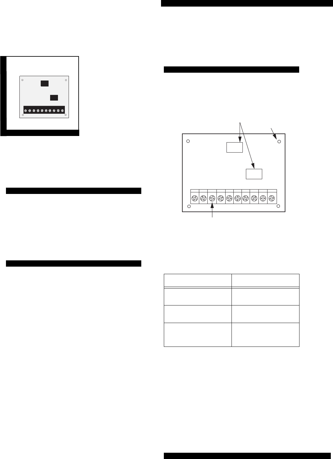
Module Components
Figure 1 shows the Module’s main components and
Table 1 describes these components.
Figure 1. Module Components
Table 1. Module Component Descriptions
Component Function
Mounting Scre w Holes Holes for wall or enclo-
sure mounting.
Relays Siren output and siren
supervision output relays.
Wiring Terminal Strip Used for p anel, panel
relay module, and siren
connections.
MOUNTING
SCREW
HOLES (4)
8457G28A.DSF
RELAYS (2)
WIRING
TERMINALS
ALL PANEL TERMINALS ARE CLASS II POWER LIMITED
60-797
8457G29A.DSF

Page 2
Regency Supervised Voice Siren Module
Installation Guidelines
■Regency security systems support one Module
per panel.
■Do not exceed the panel’s voice siren output
power (see specific panel’s Installation Instruc-
tions).
■Maximum power draw of Module and connected
siren is 1A at 12 VDC.
Tools and Supplies Needed
■Small and medium blade screwdrivers
■3/8 -inch #6-32 self-tapping screws (included)
■22-gauge (or larger) stranded hookup wire. Use
larger gauge wire for long wire runs.
Installation
The Module is mounted on a wall or inside an enclo-
sure.
CAUTION: To prevent damage to the panel or
Module, remove panel AC power and
disconnect backup battery before
installation.
Mounting the Module
1. Remove panel AC power and disconnect the
panel backup battery.
2. Place the Module on the wall or inside the enclo-
sure.
3. Secure the Module to the wall or enclosure using
the appropriate mounting screws, anchors, or
standoffs (not included).
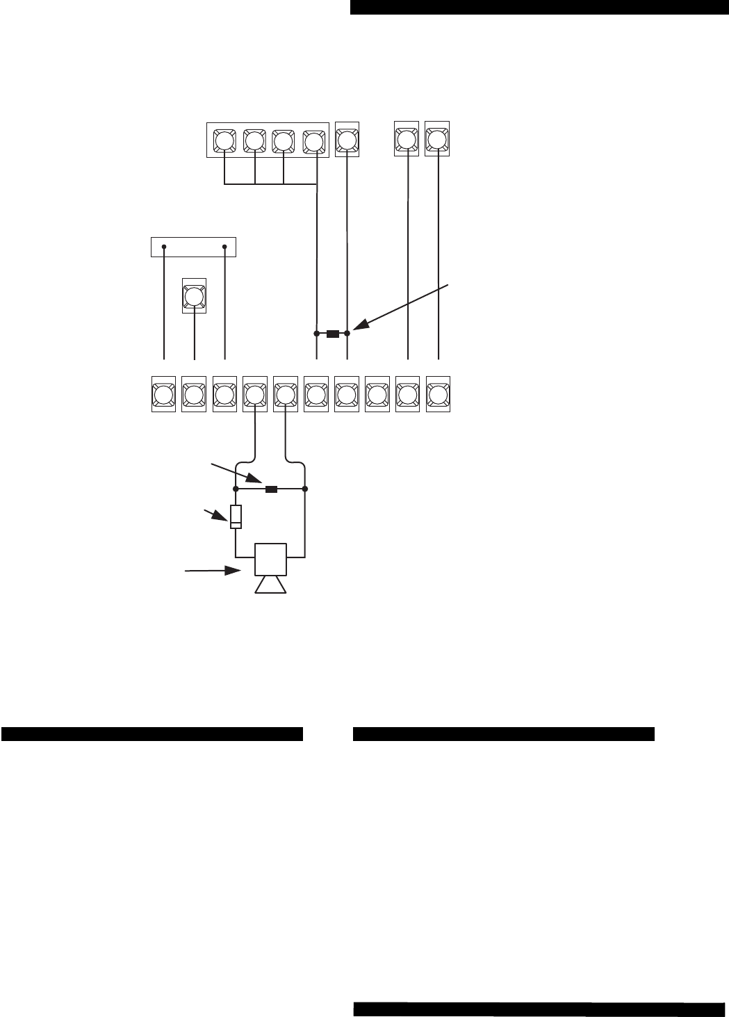
Wiring the Module
This section describes how to wire the Module to a
Regency panel, status display module, and siren.
To Wire the Module:
1. If you have not already done so, remove panel
AC power and disconnect the panel backup bat-
tery.
2. Wire the Module to the panel, status display mod-
ule, and siren as shown in Figure 2.
WARNING: You must be free of all
static electricity when handling electronic
components. Wear a grounding strap or
touch a bare metal surface before han-
dling circuit boards.
Regency Supervised Voice Siren Module
8457G30B.DSF
FIRE
4.7k Ohm
EOL RESISTOR 49-365
(LOCATE AT SIREN)
1
COM
24
BURG
35
NO
7
C
6
COM
9
NC
8
+12V
10
SIREN
+SIREN
--
+–
12V
SIREN/SOUNDER**
GND
ZONE
16*
INPUT +12V
GND
13
P3
4.7K OHM EOL RESISTOR
600-7630 (LOCATE AT
SUPERVISED SIREN MODULE)
1A, 50V DIODE**
IN 4001 07-001
(LOCATE AT SIREN)
FIRE
ALARM
INTRU-
SION
ALARM
REGENCY MODEL 4720(A)
PANEL TERMINALS
REGENCY
MODEL 4180
STATUS
DISPLAY
MODULE
CONNECTOR
AND
TERMINAL
SUPERVISED SIREN
MODULE TERMINALS
* OR ANY ZONE INPUT PROGRAMED AS A
NORMALLY-OPEN SUPERVISORY INPUT.
56
14
** NOTE POLARITY.
38
1211
ZONE LOOP POWER
13
Page 3Page 3Page 3
Figure 2. Typical Regency Panel Module Wiring
Powering Up the Panel
This section describes how to power up the panel and
the Module.
To Power Up the Panel and Module:
1. Verify that all wiring at the panel and the Module
is correct.
2. Reconnect the panel battery and restore panel AC
power.
Testing
Refer to the specific panel’s Installation Instructions
for testing siren operation and supervision.
Verify that burglary alarms produce a steady state
siren cadence and that fire alarms produce a “temporal
three” (repeating three short beeps) siren cadence.
Also verify that panel annunciates/reports a supervi-
sory when Module siren or relay outputs are cut (dis-
connected) or shorted.

Page 4
Regency Supervised Voice Siren Module
Specifications
Compatibility: Regency Model 4720, 4720A, and
Custom Versions panels with Model 4180 Status
Display Modules.
Power Requirements: 12 VDC at 1A maximum
(from panel); standby (idle) current draw of 5 mA.
Storage Temperature: -30° to 120° F (-34° to 49° C)
Operating Temperature: 40° to 100° F (4° to 38° C)
Maximum Humidity: 70% relative humidity, non-con-
densing
Siren Inputs: One fire and one burglar contact closure
inputs.
Siren Output: One 12 VDC at 1A maximum siren out-
put. Steady burglary or “temporal three” fire cadence.
Siren Supervision Output: “Form C” normally open
and normally closed relay contacts. Contacts rated 2A
at 60 VDC or 120 VAC maximum.
Ratings:
FCC Part 15, FCC Part 68
UL Listings: 864,985,1023
ULC: Commercial Fire/Burglary (pending)
CSFM: California State Fire Marshall (pending)
FM: Factory Mutual (pending)
Dimensions: 3.25" x 4.0" x 0.75" (LxWxD)
Installation: Wall or enclosure mounting
Notices
This device complies with Part 15 of the FCC rules. Operation is subject to the following
two conditions:
1. This device may not cause harmful interference.
1. This device must accept any interference received, including interference that may
cause undesired operation.
Changes or modifications not expressly approved by Interactive Technologies, Inc. can
void the users authority to operate the equipment.
ITI and Regency are registered trademarks of Interactive Technologies, Inc.
T: 651/777-2690
F: 651/779-4890
Interactive Technologies, Inc
.
2266 Second Street N orth
North Saint Paul, M N 55109-2900
Security
Automation
Fire Protection
Access Control
OETHCN SGOLIE
