NX 595E NetworX IP Communication Module Installation Manual 230553 ED03 18AUG15
2015-09-18
: InterLogix Nx-595E Installation Manual-230553-Ed03-18Aug15 NX-595E Installation Manual-230553-ED03-18AUG15 library
Open the PDF directly: View PDF ![]() .
.
Page Count: 36

NetworX Series™
NX-595E NetworX IP
Communication Module
Installation Manual
P/N 230553 • ED03 • ISS 18AUG15
Copyright
© 2015 United Technologies Corporation. All rights reserved.
This document may not be copied in whole or in part or otherwise
reproduced without prior written consent from UTC Fire & Security
Americas Corporation, Inc., except where specifically permitted under
US and international copyright law.
Trademarks and patents
NX-595E is a trademark of UTC Fire & Security Americas Corporation,
Inc. (UTCFS)
All other trademarks are the property of their respective owners.
Manufacturer
Placed on the market by:
UTC Fire & Security Americas Corporation, Inc.
3211 Progress Drive, Lincolnton, NC, 28092, USA
Authorized EU manufacturing representative:
UTC Fire & Security B.V.
Kelvinstraat 7, 6003 DH Weert, Netherlands
Intended Use
Use this product only for the purpose for which it was designed. For
the latest product information, contact your local supplier or visit us
online at http://www.interlogix.com.
FCC compliance
Class B: This equipment has been tested and found to comply with
the limits for a Class B digital device, pursuant to part 15 of the FCC
Rules. These limits are designed to provide reasonable protection
against harmful interference in a residential installation. Operation is
subject to the following two conditions. 1) This device may not cause
harmful interference. 2) This device must accept any interference
received, including interference that may cause undesired operation.
This equipment generates, uses, and can radiate radio frequency
energy and, if not installed and used in accordance with the
instructions, may cause harmful interference to radio communications.
There is no guarantee that interference will not occur in a particular
installation. If this equipment does cause harmful interference to radio
or television reception, which can be determined by turning the
equipment off and on, the user is encouraged to try to correct the
interference by one or more of the following measures:
• Reorient or relocate the receiving antenna.
• Increase the separation between the equipment and receiver.
• Connect the equipment into an outlet on a circuit different from
that to which the receiver is connected.
• Consult the dealer or an experienced radio/TV technician for help.
You may also find helpful the following booklet, prepared by the FCC:
"How to Identify and Resolve Radio-TV Interference Problems." This
booklet is available from the U.S. Government Printing Office,
Washington D.C. 20402.
Changes and Modifications not expressly approved by the
manufacturer or registrant of this equipment can void your authority to
operate this equipment under Federal Communications Commission’s
rules.

IC compliance
This Class B digital apparatus complies with Canadian ICES-003.
Cet appareil numérique de la classe B est conforme à la norme NMB-
003 du Canada.
This device complies with Industry Canada license-exempt RSS
standard(s). Operation is subject to the following two conditions: (1)
this device may not cause interference, and (2) this device must
accept any interference, including interference that may cause
undesired operation of the device.
Cet appareil est conforme avec Industrie Canada exempts de licence
standard RSS (s). Son fonctionnement est soumis aux deux conditions
suivantes: (1) cet appareil ne doit pas provoquer d'interférences et (2)
cet appareil doit accepter toute interférence, y compris celles pouvant
causer un mauvais fonctionnement de l'appareil.
EU directives
UTC Fire & Security Americas Corporation, Inc. hereby declares that
this device is in compliance with the applicable requirements and
provisions of one or more of the Directives 1999/5/EC, 2015/30/EU
and 2015/35/EU. For more information see:
www.utcfireandsecurity.com or www.interlogix.com
2012/19/EU (WEEE directive): Products marked with this symbol
cannot be disposed of as unsorted municipal waste in the European
Union. For proper recycling, return this product to your local supplier
upon the purchase of equivalent new equipment, or dispose of it at
designated collection points. For more information see:
www.recyclethis.info.
Contact information
www.utcfireandsecurity.com or www.interlogix.com
Customer support
www.interlogix.com/customer-support or www.utcfssecurityproducts.eu
4 © 2015 UTC Fire & Security Americas Corporation, Inc. All rights reserved.
Content
Important information 5
Introduction 10
Installing the NX-595E into the enclosure 11
Wiring the NX-595E 12
NX-595E Connector Layout 13
Preparing the NX-595E for Configuration 13
Enrolling, Defaulting and Retrieving the IP Address for the NX-
595E 14
Configuring the NX-595E 16
Access via an iOS or Android Application 27
FAQ - Frequently Asked Questions 28
Appendix 1 – Advanced Setup 29
UltraSync System Status Messages 34
Specifications 36

© 2015 UTC Fire & Security Americas Corporation, Inc. All rights reserved. 5
Important information
Limitation of liability
UTC FIRE & SECURITY AMERICAS CORPORATION, INC.’S SOLE
OBLIGATION OR LIABILITY IS THE REPAIR OR REPLACEMENT OF THE
PRODUCT ACCORDING TO THE LIMITED WARRANTY. TO THE MAXIMUM
EXTENT PERMITTED BY APPLICABLE LAW, IN NO EVENT WILL UTCFS BE
LIABLE FOR ANY LOST PROFITS OR BUSINESS OPPORTUNITIES, LOSS OF
USE, BUSINESS INTERRUPTION, LOSS OF DATA, LOST SAVINGS, OR ANY
OTHER INDIRECT, SPECIAL, INCIDENTAL, OR CONSEQUENTIAL DAMAGES
UNDER ANY THEORY OF LIABILITY, WHETHER BASED IN CONTRACT,
TORT, NEGLIGENCE, PRODUCT LIABILITY, OR OTHERWISE, EVEN IF UTCFS
HAS BEEN ADVISED OF THE POSSIBILITY OF SUCH DAMAGES, NOR FOR
ANY CLAIM BY ANY THIRD PARTY. BECAUSE SOME JURISDICTIONS DO
NOT ALLOW THE EXCLUSION OR LIMITATION OF LIABILITY FOR
CONSEQUENTIAL OR INCIDENTAL DAMAGES THE PRECEDING LIMITATION
MAY NOT APPLY TO YOU. IN ANY EVENT THE TOTAL LIABILITY OF UTCFS
SHALL NOT EXCEED THE PURCHASE PRICE OF THE PRODUCT. THE
FOREGOING LIMITATION WILL APPLY TO THE MAXIMUM EXTENT
PERMITTED BY APPLICABLE LAW, REGARDLESS OF WHETHER UTCFS
HAS BEEN ADVISED OF THE POSSIBILITY OF SUCH DAMAGES AND
REGARDLESS OF WHETHER ANY REMEDY FAILS OF ITS ESSENTIAL
PURPOSE.
INSTALLATION IN ACCORDANCE WITH THIS MANUAL, APPLICABLE
CODES, AND THE INSTRUCTIONS OF THE AUTHORITY HAVING
JURISDICTION IS MANDATORY.
While every precaution has been taken during the preparation of this manual to
ensure the accuracy of its contents, UTCFS assumes no responsibility for errors or
omissions.
Advisory messages
Advisory messages alert you to conditions or practices that can cause unwanted
results. The advisory messages used in this document are shown and described
below.
WARNING: Warning messages advise you of hazards that could result in injury or
loss of life. They tell you which actions to take or to avoid in order to prevent the
injury or loss of life.
Caution: Caution messages advise you of possible equipment damage. They tell
you which actions to take or to avoid in order to prevent the damage.

6 © 2015 UTC Fire & Security Americas Corporation, Inc. All rights reserved.
Note: Note messages advise you of the possible loss of time or effort. They
describe how to avoid the loss. Notes are also used to point out important
information that you should read.
Keep in mind, the level of security you will obtain with this system relates
specifically with two major factors:
• The quantity, quality, and placement of security devices attached to this security
system.
• The knowledge you have of the security system and how that knowledge is
utilized in a weekly test of the complete system.
This product is to be installed by qualified SERVICE PERSONNEL only.
General Disclaimers
A level of TCP IP knowledge is required by the installer/s to set up some of the NX-
595E functionality. UTCFS limits it support to NX-595E setup only, and is unable to
offer further assistance on your client's DSL modem, router, firewall or any other 3rd
party software. Please consult your customers IT department or qualified IT
professional about implementing this product onto your client's network.
The information in this document is subject to change without notice. UTC Fire &
Security Americas Corporation, Inc. assumes no responsibility for inaccuracies or
omissions and specifically disclaims any liabilities, losses or risks, personal or
otherwise, incurred as a consequence, directly or indirectly, of the use or
application of any of the contents of this document. For latest documentation,
contact your local supplier or visit us online at http://www.interlogix.com.
This publication may contain examples of screen captures and reports used in daily
operations. Examples may include fictitious names of individuals and companies.
Any similarity to names and addresses of actual businesses or persons is entirely
coincidental.
Limited Warranty
UTC Fire & Security Americas Corporation, Inc. guarantees this product against
defective parts and workmanship under normal use for twenty-four (24) months
from the date of purchase. If any defect appears during the warranty period contact
your service provider. UTC FIRE & SECURITY AMERICAS CORPORATION, INC.
ASSUMES NO LIABILITY FOR CONSEQUENTIAL OR INDIRECT DAMAGE,
AND ACCEPTS NO RESPONSIBILITY FOR REPAIRING DAMAGE TO THE
PRODUCT CAUSED BY MISUSE, CARELESS HANDLING, OR WHERE
REPAIRS HAVE BEEN MADE BY OTHERS. UTC FIRE & SECURITY AMERICAS
CORPORATION, INC. DOES NOT WARRANT THAT THE OPERATION OF THIS
PRODUCT WILL BE UNINTERRUPTED OR ERROR-FREE.
© 2015 UTC Fire & Security Americas Corporation, Inc. All rights reserved. 7
No other guarantee, written or verbal, is authorized by UTC Fire & Security
Americas Corporation, Inc.
PRODUCT WARNINGS
YOU UNDERSTAND THAT A PROPERLY INSTALLED AND MAINTAINED
ALARM/SECURITY SYSTEM MAY ONLY REDUCE THE RISK OF EVENTS
SUCH AS BURGLARY, ROBBERY, FIRE, OR SIMILAR EVENTS WITHOUT
WARNING, BUT IT IS NOT INSURANCE OR A GUARANTEE THAT SUCH
EVENTS WILL NOT OCCUR OR THAT THERE WILL BE NO DEATH,
PERSONAL INJURY, AND/OR PROPERTY DAMAGE AS A RESULT. UTC FIRE
& SECURITY AMERICAS CORPORATION, INC. (TOGETHER WITH ITS
PARENT CORPORATIONS, AFFILIATES AND SUBSIDIARIES,
(“INTERLOGIX”)) SHALL NOT BE LIABLE FOR ANY DEATH, PERSONAL
INJURY, PROPERTY DAMAGE, OR LOSS OF ANY KIND WHATSOEVER TO
YOU OR OTHERS, WHETHER DIRECTLY, INDIRECTLY, INCIDENTALLY,
CONSEQUENTIALLY, OR OTHERWISE, CAUSED BY THE OPERATION,
NONOPERATION, FUNCTIONING, MALFUNCTIONING, MISUSE OR
CIRCUMVENTION OF ANY PRODUCT, SOFTWARE OR SERVICES
MANUFACTURED, SOLD OR LICENSED BY INTERLOGIX.
THE ABILITY OF INTEROGIX’S PRODUCTS, SOFTWARE OR SERVICES TO
WORK PROPERLY DEPENDS ON A NUMBER OF PRODUCTS AND SERVICES
MADE AVAILABLE BY THIRD PARTIES OVER WHICH INTERLOGIX HAS NO
CONTROL INCLUDING, BUT NOT LIMITED TO, INTERNET, CELLULAR AND
LANDLINE CONNECTIVITY; MOBILE DEVICE AND OPERATING SYSTEM
COMPATIBILITY; MONITORING SERVICES; ELECTRONMAGNETIC OR
OTHER INTERFERENCE, PROPER INSTALLATION AND MAINTENANCE OF
AUTHORIZED PRODUCTS (INCLUDING ALARM OR OTHER CONTROL PANEL
AND SENSORS) AND SOFTWARE. INTERLOGIX SHALL NOT BE LIABLE FOR
ANY DAMAGES CAUSED BY ACTIONS OR OMISSIONS OF THIRD PARTIES,
INCLUDING DEALER, PROVIDING, INSTALLING AND/OR SERVICING SUCH
PRODUCTS AND/OR SERVICES.
WHILE INTERLOGIX TAKES COMMERCIALLY REASONABLE MEASURES TO
PREVENT HACKING OF ITS SECURITY PRODUCTS, SOFTWARE, AND
SERVICES, ANY SECURITY PRODUCT, SOFTWARE, SERVICE OR OTHER
OFFERING MANUFACTURED, SOLD OR LICENSED BY INTERLOGIX, MAY
STILL BE HACKED, COMPROMISED AND/OR OTHERWISE CIRCUMVENTED
AND INTERLOGIX MAKES NO WARRANTY OR PROMISE THAT ITS
SECURITY PRODUCTS, SOFTWARE, SERVICES OR OTHER OFFERINGS
WILL NOT BE HACKED, COMPROMISED AND/OR OTHERWISE
CIRCUMVENTED.
8 © 2015 UTC Fire & Security Americas Corporation, Inc. All rights reserved.
INTERLOGIX DOES NOT ENCRYPT COMMUNICATIONS BETWEEN ITS
ALARM OR OTHER CONTROL PANELS AND THEIR WIRELESS INPUTS
INCLUDING BUT NOT LIMITED TO, SENSORS OR DETECTORS UNLESS
REQUIRED BY APPLICABLE LAW. INTERLOGIX MAY NOT ENCRYPT
COMMUNICATIONS BETWEEN ITS ALARM OR OTHER CONTROL PANELS
AND THEIR WIRELESS OUTPUTS INCLUDING BUT NOT LIMITED TO,
SENSORS, DETECTORS, WIFI OR CELLULAR DEVICES, UNLESS REQUIRED
BY APPLICABLE LAW. AS A RESULT THESE COMMUNICATIONS MAY BE
INTERCEPTED AND COULD BE USED TO CIRCUMVENT YOUR
ALARM/SECURITY SYSTEM.
WARRANTY DISCLAIMERS
YOUR EXCLUSIVE REMEDY UNDER THE LIMITED WARRANTY SHALL BE
REPAIR OR REPLACEMENT OF THE PRODUCT, AT THE SOLE DISCRETION
OF INTERLOGIX EXCEPT AS EXPRESSLY PROVIDED ABOVE, THE
PRODUCT IS PROVIDED “AS IS” WITHOUT WARRANTY OF ANY KIND,
EITHER EXPRESS OR IMPLIED, INCLUDING, BUT NOT LIMITED TO, IMPLIED
WARRANTIES OF MERCHANTABILITY OR FITNESS FOR A PARTICULAR
PURPOSE AND, EXCEPT AS EXPRESSLY PROVIDED ABOVE, YOU ASSUME
THE ENTIRE RISK AS TO THE QUALITY AND PERFORMANCE OF THE
PRODUCT. INTERLOGIX HEREBY DISCLAIMS ALL OTHER WARRANTIES
AND REPRESENTATIONS, WHETHER EXPRESS, IMPLIED, STATUTORY OR
OTHERWISE, INCLUDING ANY IMPLIED WARRANTIES, THE WARRANTIES
OF MERCHANTABILITY OR FITNESS FOR A PARTICULAR PURPOSE.
INTERLOGIX DOES NOT MAKE ANY CLAIMS OR WARRANTIES TO YOU OF
ANY KIND REGARDING ANY PRODUCT, SOFTWARE OR SERVICE’S
POTENTIAL, ABILITY, OR EFFECTIVENESS TO DETECT, MINIMIZE, OR IN
ANY WAY PREVENT DEATH, PERSONAL INJURY, PROPERTY DAMAGE, OR
LOSS OF ANY KIND WHATSOEVER. INTERLOGIX IS NOT RESPONSIBLE FOR
ANY DEATH, PERSONAL INJURY, DAMAGE, LOSS, OR THEFT RELATED TO
ANY PRODUCT, SOFTWARE OR SERVICES, THEIR USE OR MISUSE, OR FOR
ANY HARM, WHETHER PHYSICAL OR MENTAL, RELATED THERETO.
INTERLOGIX DOES NOT REPRESENT TO YOU THAT ANY PRODUCT,
SOFTWARE, SERVICE OR OTHER OFFERING MAY NOT BE HACKED,
COMPROMISED AND/OR CIRCUMVENTED.
INTERLOGIX DOES NOT WARRANT THAT ANY PRODUCT OR SOFTWARE
MANUFACTURED OR SOLD BY INTERLOGIX, OR ANY RELATED SERVICE
OFFERING WILL PREVENT DEATH, PERSONAL INJURY, BODILY INJURY,
AND/OR DAMAGE TO PROPERTY OF PURCHASER, END-USER OR OTHERS
RESULTING FROM BURGLARY, ROBBERY, FIRE, OR OTHERWISE, OR THAT
© 2015 UTC Fire & Security Americas Corporation, Inc. All rights reserved. 9
THE PRODUCT WILL IN ALL CASES PROVIDE ADEQUATE WARNING OR
PROTECTION.
INTERLOGIX DOES NOT WARRANT TO YOU THAT ITS SOFTWARE OR
PRODUCTS WILL WORK PROPERLY IN ALL ENVIRONMENTS AND
APPLICATIONS AND DOES NOT WARRANT ANY PRODUCTS AGAINST
HARMFUL ELECTROMAGNETIC INTERFERENCE INDUCTION OR RADIATION
(EMI, RFI, ETC.) EMITTED FROM EXTERNAL SOURCES
INTERLOGIX DOES NOT PROVIDE MONITORING SERVICES FOR YOUR
ALARM/SECURITY SYSTEM (“MONITORING SERVICES”). IF YOU ELECT TO
HAVE MONITORING SERVICES YOU MUST OBTAIN SUCH SERVICE FROM A
THIRD PARTY AND INTERLOGIX MAKES NO REPRESENTATION OR
WARRANTY WITH RESPECT TO SUCH SERVICES INCLUDING WHETHER OR
NOT THEY WILL BE COMPATIBLE WITH THE PRODUCTS, SOFTWARE OR
SERVICES MANFUFACTURED OR SOLD BY INTERLOGIX.
(USA only) SOME STATES DO NOT ALLOW THE EXCLUSION OF IMPLIED
WARRANTIES, SO THE ABOVE EXCLUSION MAY NOT APPLY TO YOU. THIS
WARRANTY GIVES YOU SPECIFIC LEGAL RIGHTS AND YOU MAY ALSO
HAVE OTHER LEGAL RIGHTS THAT VARY FROM STATE TO STATE.

10 © 2015 UTC Fire & Security Americas Corporation, Inc. All rights reserved.
Introduction
The NX-595E is an IP communication module that can be added to a NetworX V2
family security product (NX-4, NX-6, NX-8, NX-8E) to provide remote access and
alarm reporting via standard Internet connections (IP). The NX-595E can utilize two
connection methods to your central monitoring station. It can connect directly to an
Osborne Hoffman (OH) NetRec receiver. Alternatively, it can use UltraSync™
services. Contact your central monitoring station to determine their preferred
connection method.
The security panel can be configured for alarm reporting exclusively over IP when
PSTN connectivity is no longer available. Alternatively, it can utilize the PSTN for
failover connectivity in the event the IP communications path is lost.
The NX-595E provides a web browser interface accessible via a local computer,
smart phone or tablet to configure the device. Additionally, UltraSync™, an Apple®
iOS® or Android® application, is available for remote configuration and end user
control of the security system including control of two output relays. Up to four
zones are also supported with zone doubling (not available on NX-4 panels). Three
email addresses can be programmed into the NX-595E to allow alarm and trouble
events to be emailed to the end user.
This manual assumes the installer is familiar with the NetworX V2 family of security
products and is capable of programing the security system. It also assumes that the
installer is familiar with basic computer networking and Apple iOS or Android smart
devices.
Setup is a simple process:
1. Install the NX-595E into the NetworX panel.
2. Enroll the NX-595E into the NetworX panel.
3. Minimum configuration is required:
a. Time and daylight savings setup (Feature Menu)
b. IP Reporting (IP Reporting Menu)
c. Enable remote UltraSync application support by setting the Web Access
Passcode (Network Settings Menu)
Important notes before proceeding
• The PINs for accessing the NX-595E are stored in the NetworX panel. Make
sure you are using the existing PIN for the Installer when configuring the NX-
595E.
• Record the following information in the UltraSync Quick Reference Guide during
the installation process:
• NX-595E serial number (12-digits)
• Web Access Passcode (8- numerical digits)
© 2015 UTC Fire & Security Americas Corporation, Inc. All rights reserved. 11
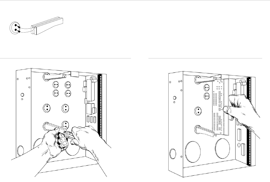
Installing the NX-595E into the enclosure
Inside the NetworX enclosure, several 2-holed insertion points have been
constructed. This allows for either vertical or horizontal placement of the module.
Note: Notice that the insertion points have two sizes of holes - a larger hole and a
smaller hole.
Figure 1: The black plastic PCB guides have slots along the straight edge where
the PC Board will be seated. The curved side of the PCB guide fits into the larger
hole. The smaller hole on the raised protrusion in the NetworX panel is for the
screw.
Figure 2: Place the first black plastic PCB guide in the top insertion point with the
PCB slot facing downward. It does not require force. Insert one of the screws into
the smaller hole to secure it in place. The second PCB guide should be positioned
opposite of the first guide and placed in the lower insertion point, using the same
procedures described above. Once mounted, screw it in securely.
Figure 3: The PC board should slide freely in the slots of both guides.
Figure 1
Figure 2
Figure 3
Note: Record the 12 digit serial number of the NX-595E on the back of the
UltraSync Quick Reference Guide that is included in the product packaging. The
serial number is located on NX-595E product label attached to the PCB.

12 © 2015 UTC Fire & Security Americas Corporation, Inc. All rights reserved.
Wiring the NX-595E
Caution: Remove all power (AC and battery) to the NetworX security system
before proceeding. Failing to do so could result in possible damage to the product.
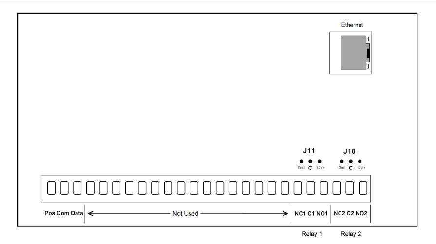
Terminal descriptions
Terminal
Description
1
Pos
Panel
Bus
Positive terminal
2
Com
Common terminal
3
Data
Data terminal on the NetworX panel
14
Z1
Additional
Zones
1st / 3rd Zone
3.3K = Single EOLs
3.7K = Low zones
6.9K = High zones
15
Com
Common (-) return for Zone
loop
16
Z2
2nd / 4th Zone
20
NC1
Relay 1
Normally closed
This relay can be controlled
from the UltraSync application
21
C1
Common
22
NO1
Normally open
23
NC2
Relay 2
Normally closed
This relay can be controlled
from the UltraSync application
24
C2
Common
25
NO2
Normally open
1. Connect the NX-595E's terminals POS, COM & DATA to the NetworX bus.
2. Connect one end of an Ethernet cable to the RJ45/Ethernet connector on the
NX-595E. Connect the other end of the Ethernet cable to an available Ethernet
port on the Internet router. The router should automatically assign the NX-595E
module an IP address when it is powered up.
3. If you are utilizing the output relay or additional zone functionality of the NX-
595E, connect the wiring to the appropriate terminals. Additional instructions
regarding output relay and zone functionality are included this manual.
4. Re-connect the power to the NetworX security system. You are now ready to
configure the NX-595E.
Note: In the unlikely event that the Internet router is not configured to automatically
assign an IP address, you will have to manually assign an IP address and network
settings in the NX-595E. Instructions to manually assign the network settings are
included in Appendix 1 at the end of this manual.
© 2015 UTC Fire & Security Americas Corporation, Inc. All rights reserved. 13
NX-595E Connector Layout
Figure 4
Preparing the NX-595E for Configuration
Before you can configure the device, you must:
1. Enroll the NX-595E in the NetworX panel.
2. Default the NX-595E.
3. Retrieve the IP address from the NX-595E.
You can accomplish these three steps via any LCD (NX-148xx), Voice (NX-181xx)
or touchscreen (NX-182xx) keypad.
14 © 2015 UTC Fire & Security Americas Corporation, Inc. All rights reserved.
Enrolling, Defaulting and Retrieving the IP
Address for the NX-595E
The NX-595E is automatically set to device address 191 and programming is
carried out like all other NetworX modules.
Default the NX-595E following these instructions depending on the type of keypad
you are using. When you exit program mode, the NX-595E will be automatically
enrolled.
Using a NX-181xx Voice keypad
Step
1.
[MENU]-[0]
Selects main menu - Option 0, Advanced system
configuration
Enter your code, touch menu to exit.
2.
[?]-[?]-[?]-[?]
Enter your 4 or 6 digit Programming code
Touch 1 for keypad configuration
Touch 2 for panel and device configuration
Touch 3 to configure service provider phone
number
Touch menu to exit.
3.
[ 2 ]
Selects Panel and Device configuration
Select a device number followed by enter
Touch menu to go back.
4.
[ 1 ][ 9 ][ 1 ]
[ENTER]
Connects to device 191 (NX-595E)
Selected device 191 is connected.
Select a Location number followed by enter
Touch menu to go back.
5.
[ 9 ][ 1 ][ 0 ]
[ENTER]
Defaults the device, Note: only required once
6.
[2][1]
[Enter]
This keypad will announce the first number of the IP
address
7.
[MENU]
This keypad will announce the second number of the
IP address
8.
[MENU]
This keypad will announce the third number of the IP
address
9.
[MENU]
This keypad will announce the fourth number of the IP
address
10..
[MENU]
Moves back to step 4, select a device number
11.
[MENU]
Moves back to step 3, Advanced system configuration
selection.
12.
[MENU]
Exits from Advanced system configuration. (exiting
program mode automatically enrolls the NX-595E)
© 2015 UTC Fire & Security Americas Corporation, Inc. All rights reserved. 15
Using a NX-182xx touch screen keypad
Step
1.
[MENU]
Press the Menu button
2.
[Settings]
Press the Settings button
3.
[?]-[?]-[?]-[?]
Enter your 4 or 6 digit Programming code
4.
[ Program]
Press the Program button
5.
[ 1 ][ 9 ][ 1 ]
[ENTER]
Connects to device 191 (NX-595E)
6.
[ 9 ][ 1 ][ 0 ]
[ENTER]
Defaults the device, Note: only required once
7.
[ 2 ][ 1 ]
[ENTER]
Access location 21 to retrieve the IP address of the
NX-595E. Scroll through the segments with the ►
button and record the IP address (e.g. 192.168.1.2)
8.
[Exit]
Press the Exit button. (exiting program mode
automatically enrolls the NX-595E)
Using a Standard Keypad (Icon or LCD)
Step
1.
[ * ] [ 8 ]
Selects Panel and Device programming
2.
[?]-[?]-[?]-[?]
Enter your 4 or 6 digit Programming code
3.
[1][9][1] - [#]
Connects to device 191 (NX-595E)
4.
[9][1][0] - [#]
Defaults the device, Note: only required once
5.
[2][1][#]
To discover the IP address of the NX-595E (Press * to
scroll through each segment of the IP address. Record
the IP address (e.g. 192.168.1.2)
6.
[Exit]
Moves back to step 3
7.
[Exit]
Exits programming (exiting program mode
automatically enrolls the NX-595E)
16 © 2015 UTC Fire & Security Americas Corporation, Inc. All rights reserved.
Configuring the NX-595E
You have two options to configure the device.
• A direct connection with a web browser on a computer or mobile device
• Via the UltraSync application on an Apple iOS or Android device
Note: Before you can utilize the UltraSync application to configure the NX-595E,
you must program in the Web Access Passcode in the Network Settings tab. It is
recommended that the initial configuration of the device be completed with a web
browser.
There is limited configuration capability with a connected keypad. Please see
Appendix 1 – Advanced Setup for keypad worksheets for more information.
Configuring the NX-595E (Web browser or UltraSync)
Note: Configuration of the NX-595E with a web browser and the UltraSync
application is virtually identical. The screenshots below show the Web browser view
when configuring the device.
• If you are using a computer, you can connect your computer to the same router
that the NX-595E is connected to with an Ethernet cable.
• If you are using WiFi to access the network (e.g. with a tablet, WiFi enabled
computer or smart phone), make sure the WiFi router is connected to the same
network that the NX-595E is connected to.
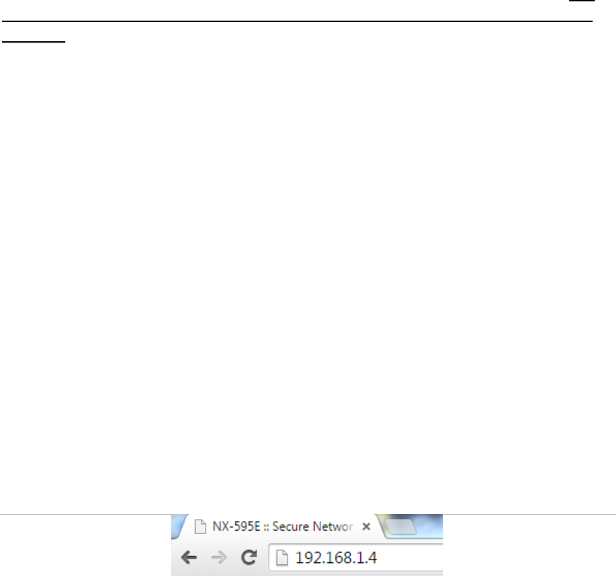
Enter the IP address of your NX-595E into the web browser to access the NX-595E.
This is the IP address that was retrieved above in the Enrolling, Defaulting and
Retrieving the IP Address section of this document.
Figure 5
Note: The IP address that was retrieved from the device was most likely assigned
by the network router. If the router or NX-595E is reset, power cycled, or a long
period of time has expired since you retrieved the IP address, a new IP address
might be assigned to the NX-595E. If the IP address you are using is not working,
retrieve the IP address with the instruction in the Enrolling, Defaulting and
Retrieving the IP Address section of this document. You do not need to perform the
defaulting portion of these instructions when retrieving the IP address.
© 2015 UTC Fire & Security Americas Corporation, Inc. All rights reserved. 17
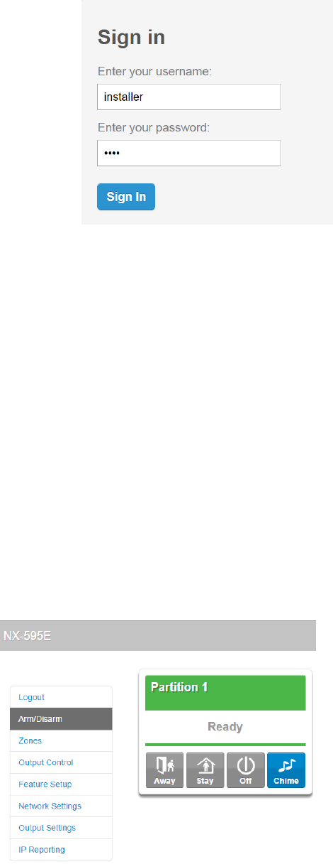
Sign in Page
When successfully connected, the NX-595E will display the “Sign in” Page. Enter
the correct username/password combination to login.
• Default Installer Username: installer (username is case sensitive)
• Password: (enter the NetworX panel programming code)
Notes:
1. The password used to log into the NX-595E is the programming code that
resides in the NetworX panel.
2. The Username used to log into the NX-595E is stored in the NX-595E. The
default installer name can be changed on the Feature Setup menu after you
have logged in.
Note: Logging in as the installer will not allow programming of the NetworX panel.
Main Menu (Accessed with Installer Credentials)

18 © 2015 UTC Fire & Security Americas Corporation, Inc. All rights reserved.
Feature Setup
Enable Zone Doubling: Allow the two onboard zones to double to four zones (not
available on NX-4 panels). These zones cannot be used for 2-wire smoke
detectors.
Start Zone: Used to enter the starting zone number of the additional zones on the
NX-595E. Select from the drop down menu.
Installer Name: Default installer name is installer and is case sensitive. This is
the username to sign in via a web browser or the UltraSync application.
Service Number: The system service number will be announced at NX-181xx
Voice keypads when a system fault is present. Your customer service telephone
number is the recommended setting.
GMT Offset Hours/Minutes: Sets local GMT (Greenwich Mean Time).
DST Start / End month: Selects the month daylight savings begins and ends for
the particular installation region.
DST Start / End week: – Selects which Sunday daylight savings begins and ends
for the particular installation region.
Firmware, Hardware, Web version, Voice and Language: Displays the current
versions loaded on the connected NX-595E.
Zone
Lower
Zone
Higher
Zone
Single EOL resistors
3.3K
N/A
N/A
Zone Doubled EOL resistors
N/A
3.7K
6.9K
© 2015 UTC Fire & Security Americas Corporation, Inc. All rights reserved. 19
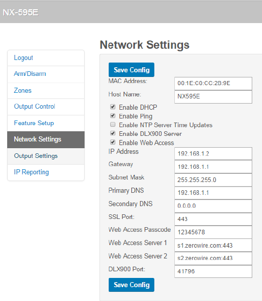
Network Settings
MAC Address: Media Access Control address (MAC address) is a unique identifier
assigned to most network interface cards by the manufacturer for identification.
Host Name: Fixed as “NX595E.”
Enable DHCP: When enabled, the NX-595E will automatically receive its IP
address from the network router. If this segment is disabled, the NX-595E will need
to have its IP address set manually. It is recommended that DHCP be enabled.
Enable Ping: The “Ping” command is always functional while the NX-595E is in
program mode. Disable this option to allow the NX-595E to ignore "ping"
commands in normal operation. For security reasons it is recommended this option
be disabled.
Enable NTP Server Time Updates: The NX-595E will check its internal clock and
use the internet to compare it against GMT time. This is done every 15min and will
update itself if the variance is greater than 3 minutes.
Enable DLX900 Server: Allows remote configuration using DLX900 software.
Disable to prevent DLX900 connections to the NX-595E. Enabled by default and for
the first 5 minutes after power up. Note that this option does not prevent DLX900
connections to the panel via PSTN, disable this in panel programming if required.
Enable Web Access: When enabled, email and IP reporting will function.
Alternatively, if the Web Access Passcode is set to a non-zero value, email and IP
reporting will function.
IP Address: IP address of the NX-595E module. If Enable DHCP is unchecked,
this field is editable and a static IP address can be assigned manually.

20 © 2015 UTC Fire & Security Americas Corporation, Inc. All rights reserved.
Gateway: IP address of the gateway device (e.g. WiFi router, DSL or cable
modem). If Enable DHCP is unchecked, this field is editable and the IP address of
the gateway can be assigned manually in the NX-595E.
Subnet Mask: Subnet mask of the local area network (LAN). If Enable DHCP is
unchecked, this field is editable and the subnet mask can be assigned manually.
Primary DNS: IP address of the primary DNS server (editable if Enable DHCP is
unchecked).
Secondary DNS: IP address of the secondary DNS server (editable if Enable
DHCP is unchecked).
SSL Port: Not used.
Web Access Passcode: This code allows the UltraSync iPhone and Android
applications to connect to the security system, and enables email and IP reporting.
A value of 00000000 disables UltraSync application support. Enter a unique Web
Access Passcode (eight numerical digits only) and click the Save Config button to
enable UltraSync application support. Record the Web Access Passcode on the
back of the UltraSync Quick Reference Guide.
Web Access Server 1: This server address should not be changed. It enables the
remote web access, UltraSync iPhone and Android applications and email services.
Web Access Server 2: This server address should not be changed. It enables the
remote web access, UltraSync iPhone and Android applications and email services.
DLX900 Port: Enter the port number for DLX900 access. Default value 41796.
© 2015 UTC Fire & Security Americas Corporation, Inc. All rights reserved. 21
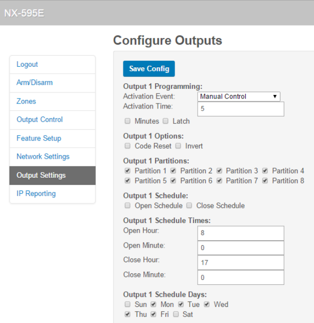
Output Settings
The two onboard relays can be controlled through various system events or
manually controlled by a user from the UltraSync application.
Relay trigger events are selectable and can be chosen from a drop down
“Activation Event” list from within the web interface.
Activation Event: Select the required event from the drop down list that will
activate the corresponding relay.
Activation Time: Time the relay will be active, options 0-255. Default value is in
seconds unless Minutes option is checked.
Minutes: On if output should be timed in minutes; off if timed in seconds.
Latch: On if output should latch permanently until turned off; off if output should be
timed.
Code Reset: On if output should stop timing upon code entry; off if output should
follow timer.
Invert: On if output should be inverted.
Output Partitions: Is used to select the partition(s) the event must occur within
before the output will activate.
Open Schedule: On if output should only activate between the opening and closing
time.
22 © 2015 UTC Fire & Security Americas Corporation, Inc. All rights reserved.
Close Schedule: On if output should only activate between the closing and
opening time.
Schedule Times: Sets the Opening / Closing hours and minutes (24 hour format)
and the days of the week the event must occur in before the output will activate.
Output Schedule Days: Is used to select the days the event must occur within
before the output will activate.
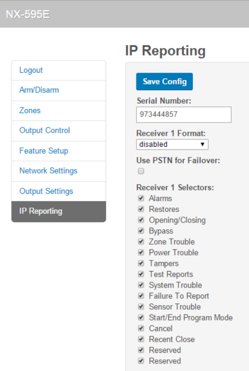
IP Reporting
Serial Number: This is the serial number for the NX-595E. This field is not editable.
Use PSTN for Failover: If IP reporting fails, switch to the alarm panel dialer for
backup communication path (only valid when PSTN line is connected).
Note: In order to prevent dual reporting (IP and PSTN) when selecting the Use
PSTN for Failover option, it will be necessary to change the panel configuration.
This is accomplished by programming Location 4, segments 1 and 2 in the NetworX
panel for Phone 1 Events Reported. Disable options 1-6 and 8 (option 7 must
remain on) for Segment 1. Disable all options (1-8) for Location 4, Segment 2 also.
If using phone 2 and 3 (locations 10 and 16) respectively, disable the
corresponding options for segments 1 and 2 as described above.
© 2015 UTC Fire & Security Americas Corporation, Inc. All rights reserved. 23
Receiver Selectors: Select the events you want to report to the IP receiver.
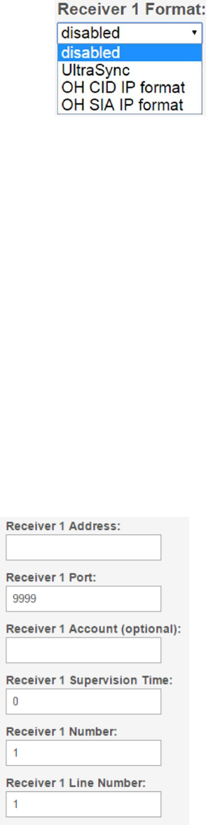
Receiver Format: This is the signal format for the central monitoring station.
There are four options when selecting the receiver format, disabled, UltraSync, OH
CID IP format and OH SIA IP format.
Disabled: IP Event reporting to the monitoring station is disabled, PSTN reporting
is used. UltraSync capabilities are still available to the installer and end users.
UltraSync: When the UltraSync format is selected, reporting to the monitoring
station is routed through the UltraSync cloud infrastructure. Once the NX-595E is
installed and a connection is made to the Internet, the NX-595E must be
provisioned in the UltraSync Portal before event reporting will be routed to the
monitoring station. Integration of network routers in the monitoring station is
required. Contact your Interlogix account representative or monitoring station for
more details.
OH CID and SIA IP format: If your monitoring station already supports Osborne
Hoffman (OH) NetRec software, the NX-595E can report immediately without any
further integration. Select the appropriate format (CID or SIA) that is supported in
the monitoring station. You will be presented with the following configuration
options:
Receiver Address: The IP address of the Osborne Hoffman receiver.
Receiver Port: The port number of the Osborne Hoffman receiver.
24 © 2015 UTC Fire & Security Americas Corporation, Inc. All rights reserved.
Receiver Account (optional): This field accepts up to 6 Hex digits. If this field is
programmed, all events sent to the receiver will use this account code. If this field is
left blank, the 595E will use the account code that is programmed into the NetworX
panel when reporting events. This field in generally used when PSTN for failover
reporting is enabled and is used to differentiate event delivery via IP or PSTN.
Receiver Supervision Time: The desired time interval in seconds that the
supervision heartbeat is sent to the receiver. A value of 0 disables supervision.
Receiver Number: The receiver number provided by the monitoring station.
Receiver Line Number: The receiver line number provided by the monitoring
station.
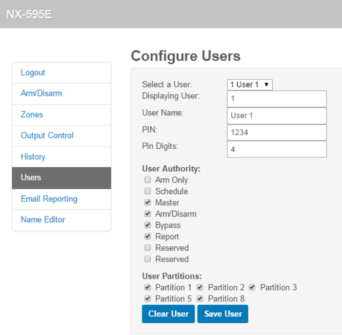
Users
Note: The User configuration menu is only accessible when logged in as a Master
User. The default username (Name) is “User 1”. You must use the Master PIN that
is programmed into the NetworX panel to access this menu.
Important: It is strongly recommended that you have the security panel owner
change the default Name (User 1) for the Master User of the system at the time of
installation.
© 2015 UTC Fire & Security Americas Corporation, Inc. All rights reserved. 25
Additional users on the NetworX panel must be assigned a name on this page to
permit them access to the UltraSync application. By default User 1 is the only user
that is pre-assigned a user name in the NX-595E.
PIN codes can also be changed or added from this page.
PIN codes are generally four digits in length, but can be configured to be six digits
in length if this level of security is required. Refer to the NetworX panel installation
manual for additional information.
The User Authority determines the options available to that user:
• Arm Only – allows the user to only arm partitions and prevents disarming
• Schedule – allows disarm only during Open Window and arming after Close
Window (see NetworX installation manual)
• Master – allows this user to create, delete or modify users. Master access
always allows arming and disarming. Users can only assign partitions to users
they have access to.
• Arm/Disarm – allows this user to arm and disarm partitions they have access to
• Bypass – allows this user to bypass zones
• Report – send open and close reports when this user arms and disarms
partitions
• User Partitions – select the partitions the user will be allowed to access and
control.
Note: The “User 1” user name is programmed into the NX-595E by default for User
1 in the NetworX panel. A user name must be created for all other users if they are
to have access to the panel via the UltraSync application. The Master user/User 1
should change their user name to something more user friendly after they log in.
The installer account is for installer access only and allows panel programming. It is
not recommended to provide this code to the end-user.

26 © 2015 UTC Fire & Security Americas Corporation, Inc. All rights reserved.
Partition Removal via Panel Programming
Note: NetworX panel default configuration has all zones assigned to
partition 1. The result of this default configuration is the GUI and UltraSync
application displays all of these zones to the end user, even if they are not
installed in the panel. It is recommended practice to “remove” unused
zones from the NetworX panel. This is accomplished by removing the
partition assignment from all unused zones. To accomplish this task, you
will have to access the panel via the keypad. Deselect partition 1 for zones
that are not installed in the panel. Access device 0, Location 26-36 (even
locations only) to accomplish this task. See the table below for more
information.
Zone Partition Assignment
Device
Zones
Location
Segment
Action
0
1-8
26
1-8
Deselect all partitions from each
segment if zone is not installed in the panel
9-16
28
1-8
17-24
30
1-8
25-32
32
1-8
33-40
34
1-8
41-48
36
1-8
Example, Zone 26 would be programmed with Location 32, Segment 2.
Configuring the NX-595E with the UltraSync application
The configuration procedure with the UltraSync application is identical to the
procedure described above for a web browser. Follow the instructions below to
install and configure the UltraSync application.
© 2015 UTC Fire & Security Americas Corporation, Inc. All rights reserved. 27
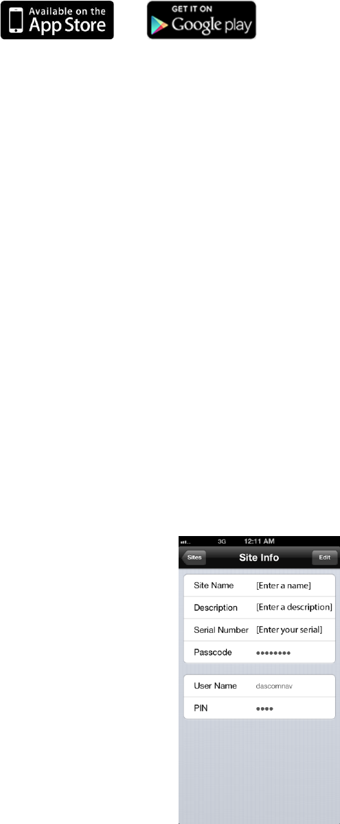
Access via an iOS or Android Application
The NX-595E can also be accessed from a dedicated application. This application
is available to download from the Apple App StoreTM or Google Play™ store.
Carrier charges may apply and an iTunes® or Google account is required.
All functionality available from the web server is available within the application.
1) On your smart device, go to the Apple App Store or Google Play store.
2) Search for UltraSync.
3) Install the UltraSync application.
4) Launch the UltraSync application.
5) Click + in the upper right corner of the screen to add a new site location.
6) Enter the details of the security system:
• Site Name: Enter a unique name for the site.
• Description: Enter a description for the site.
• Serial Number: Enter the serial number of the NX-595E. This is a 12
digit number.
• Passcode: Enter the Web Access Passcode that was programmed into
the NX-595E. This is an eight digit numerical code.
• User Name: Enter the username of the individual.
• PIN: You can elect to remember the PIN or not. If you turn Remember
PIN on, you can enter the individual’s PIN into the application and the
application will launch automatically without requiring the user to enter
their PIN.
7) Select the Add Site button to save.
8) Click the name of the Site, the app will now connect you to the NX-595E.
28 © 2015 UTC Fire & Security Americas Corporation, Inc. All rights reserved.
Troubleshooting
• NX-595E may not work on a corporate network due to firewalls, proxy servers,
and other security settings. Connect it to a network port that can provide direct
access to the internet.
• Check that other devices on the same network can connect to the internet, if
they are working then confirm all access codes are correct (serial number, Web
Access Passcode, username and PIN)
FAQ - Frequently Asked Questions
1. What if I cannot connect to NX-595E with my computer?
a. Check that the router has DHCP enabled. .
b. Check that an IP address has been allocated in Location 21 of the NX-595E
via the keypad. If it is 0.0.0.0 then DHCP is not working correctly. You may
have to assign the NX-595E a static IP address in Location 21 if the network
router does not have DHCP enabled. Make sure that the router is on the
same subnet as your computer and that the IP address is not used by
another device.
c. While the NX-595E is in program mode: On a windows computer, click Run,
type cmd to bring up a command line prompt. Type ping [ip address] then hit
Enter. If there is an error you will see 100% packet loss or "Request timed
out" responses, check your network and wiring and try again. If you see a
“reply from” the IP address then your computer is communicating with the
NX-595E.
2. I’m not receiving any emails
a. Perform testing using a standard user PIN, the installer account by default
does not send all reports.
b. Check that the emails are not being captured in your SPAM folder or blocked
by a firewall.
c. Check that the email address is entered correct in Email Reporting settings
(logged in as Master user).
d. Check that the event is checked in Email Reporting settings (logged in as
Master user).
e. Check that you are receiving other emails.
f. Check that the relevant reporting options are enabled in the panel
programming.
g. Try using the UltraSync app to verify your system is connecting to the
servers.
© 2015 UTC Fire & Security Americas Corporation, Inc. All rights reserved. 29
Appendix 1 – Advanced Setup
This section contains advanced setup information that may be required depending
on the network environment and feature utilization of the NX-595E.
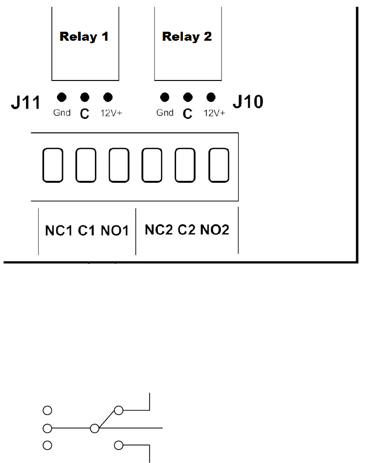
Output Relay Setup
The NX-595E features two Single Pole Double Throw (SPDT) Form C relays that
can be configured in 3 different modes to support different applications.
The relays are connected to the output terminals with Normally Open and Normally
Closed connections for your convenience.
Use jumpers on J10 and J11 to select the mode suitable for your requirements.
The NX-595E ships with no jumper installed. The Default relay position is in the NC
(normally closed) position.
Jumper J10/J11
Output
C
NC
NO
O
12V +
GND
C
Common C

30 © 2015 UTC Fire & Security Americas Corporation, Inc. All rights reserved.
No Jumper (Dry Contact Switching)
Dry contact closure provided to output terminal. Maximum Load 30 VAC @ 1 A or
24 VDC @ 1 A. DO NOT exceed these ratings.
Jumper between GND and C (Negative Switching)
Bus Ground provided to output terminal @ typical 0V. Do not exceed relay rating
which is maximum load 30 VAC @ 1 A or 24 VDC @ 1 A.
Jumper between C and 12 V + (Positive Switching)
Bus Voltage provided to output terminal @ typical 12-13 VDC. Maximum Load @
12 V is total panel current; this includes all connected keypads and expansion
modules. Consult your panel’s specifications for maximum current rating. Do not
exceed relay current rating of 1A.
Caution: Do not exceed the Maximum Load ratings above for the relay
configuration. Exceeding the maximum rating could result in possible damage to the
product.
WARNING: DO NOT CONNECT MAINS VOLTAGE TO THE NX-595E. DOING SO
COULD DAMAGE THE MODULE OR NETWORX PANEL AND POSE AN
ELECTRICAL HAZARD THAT COULD RESULT IN A FIRE OR CAUSE SERIOUS
ELECTRICAL SHOCK OR LOSS OF LIFE.
Current Limit Caution: Check the current requirements of your load before
connecting! There is no overcurrent protection on the relays when providing bus
ground or bus voltage (jumper between GND and C, or C and 12 V +). You must
ensure your load does not exceed the recommended limits above. Exceeding limits
can damage the module. NetworX panels do have overcurrent protection on the
bus and may disconnect the bus to provide temporary protection. If enabled, your
panel will report "Overcurrent Fault" or "Expander Overcurrent". Repeated
overcurrent conditions can result in permanent damage to the panel or connected
devices.
Advanced Network Setup
If the IP address is empty (Location 21, Segment 1 will be 0 in the NetworX panel),
then you will have to manually program the network settings into the NX-595E. This
is an unlikely scenario as most routers are configured to automatically assign
network settings with DHCP. Before you manually configure the NX-595E, verify
with the network administrator or home owner that they have disabled DCHP in the
router. You will need the following settings from the network administrator or home
owner if they have DHCP disabled:
© 2015 UTC Fire & Security Americas Corporation, Inc. All rights reserved. 31
• IP Address: ____.____.____.____
• Gateway: ____.____.____.____
• Subnet Mask: ____.____.____.____
• Primary DNS (if applicable): ____.____.____.____
• Secondary DNS (if applicable): ____.____.____.____
You must enter these settings via the NetworX keypad. Enter program mode on the
keypad and enter device address 191.
Step 1: Turn off DHCP.
1. Enter location 19.
2. Disable option 1.
Step 2: Manually enter network settings.
1. Enter location 20 (Gateway IP address).
a. There are four segments associated with the Gateway IP address
(Router IP address). Example address is shown below:
i. Segment 1: 192
ii. Segment 2: 168
iii. Segment 3: 1
iv. Segment 4: 1
2. Enter location 21 (IP address).
a. There are four segments associated with the IP address (NX-595E IP
address). Example address is shown below:
i. Segment 1: 192
ii. Segment 2: 168
iii. Segment 3: 1
iv. Segment 4: 100
3. Enter location 22 (Subnet Mask).
a. There are four segments associated with the Subnet Mask. Example
Subnet Mask is shown below:
i. Segment 1: 255
ii. Segment 2: 255
iii. Segment 3: 255
iv. Segment 4: 0
4. Enter location 23 (DNS Server 1).
a. There are four segments associated with the DNS Server. Example
DNS Server is shown below:
i. Segment 1: 192

32 © 2015 UTC Fire & Security Americas Corporation, Inc. All rights reserved.
ii. Segment 2: 168
iii. Segment 3: 1
iv. Segment 4: 1
5. Enter location 24 (DNS Server 2).
a. Follow the same steps as setup for DNS Server 1.
Configuring the NX-595E with the NetworX panel keypad -
Worksheets
Location 0: Reserved
Location 1:
Segment 1:
Option 1: Zone Doubling: When enabled, this feature will allow the two onboard zones to
double to four zones. Please refer to feature 18 for starting zone number. If this feature is
unselected, both onboard zones remain as single end of line zones and require 3.3K resistors.
When Zone doubling is enabled, Lower zones = 3.7K, Higher zones = 6.9K (not available on NX-
4 panels).
Options 2-8: Reserved
Segment 2-3: Reserved
Location 2-17: Reserved
Location 18: Zone Starting Number:
Location 18 is used to enter the starting zone number of the additional zones on the NX-595E. The
two zones can also be zone doubled, please refer to feature 1 to enable the zone doubling feature.
0 = Disabled.
Data
Zones
Data
Zones
Data
Zones
Data
Zones
9
=
9 - 12
41
=
41 - 44
73
=
73 - 76
105
=
105 -108
17
=
17 - 20
49
=
49 - 52
81
=
81 - 84
113
=
113 - 116
25
=
25 - 28
57
=
57 - 60
89
=
89 - 92
121
=
121 - 124
33
=
33 - 36
65
=
65 - 68
97
=
97 - 100
Location 19 - IP Feature Options
Location 19 is used to set required network settings.
Segment 1:
Option 1: Enable DHCP: When enabled, the NX-595E will automatically receive its IP address
from the network router. If this Option is disabled, the NX-595E will need to have its IP address
set manually. It is recommended that this Option be enabled.
Option 2: Reserved
Option 3: Enable Web Update: When enabled, allows updating of the NX-595E Configuration
Server's web pages via FTP. Normally disabled.
Option 4: Enable Ping: The “Ping” command is always functional while the NX-595E is in
program mode. Disable this option to allow the NX-595E to ignore "ping" commands in normal

© 2015 UTC Fire & Security Americas Corporation, Inc. All rights reserved. 33
operation. For security reasons it is recommended this option be disabled.
Option 5: Enable NTP Server Time Updates: The NX-595E will check its internal clock and
use the internet to compare it against GMT time. This is done every 15min and will update itself
if the variance is greater than 3 minutes.
Option 6: When enabled an installer will automatically have access to Feature Setup, Network
settings, Output settings and IP reporting via the NX-595E's web pages. Otherwise the NX-
595E will need to be in program mode to access these additional features. By default this is on.
Option 7: Enable DLX900 Server: Allows remote configuration using DLX900 software.
Disable to prevent DLX900 connections to the NX-595E. Enabled by default and for the first 5
minutes after power up. Note this option does not prevent DLX900 connections to the panel via
PSTN, disable this in panel programming if required.
Option 8: Enable Web Access: When enabled, email and IP reporting will function. If the Web
Access Passcode is set to a non-zero value, email and IP reporting will function.
Segment 2: Reserved
Location 20 - IP Gateway
The 4 segments in Location 20 are used to view or set the IP address of the network gateway. If
you have disabled DHCP, you must manually set the IP address of the NX-595E
In homes, the gateway is usually the Internet Service Provider (ISP) device that connects the
user to the internet, such as a DSL or cable modem.
In an enterprise system, the gateway is the node that routes the traffic from a workstation to
another network segment. The default gateway is commonly the node connecting the internal
networks and the outside network (Internet).
Segments 1 - 4
Location 21 - NX-595E IP Address
The 4 segments in Location 21 are used to view or set the IP address of the NX-595E.
Segments 1 - 4
Location 22 - Subnet Mask
The 4 segments in Location 22 are used to view or set the Subnet mask.
Segments 1 - 4
Location 23 - DNS Server 1
The 4 segments in Location 23 are used to view or set the networks DNS server address.
Segments 1 - 4
Location 24 - DNS Server 2
The 4 segments in Location 24 are used to view or set the networks DNS server address.
Segments 1 - 4
Location 25 - Reserved
Segments 1 - 4
Location 26 - Reserved
Segments 1 - 4
34 © 2015 UTC Fire & Security Americas Corporation, Inc. All rights reserved.
UltraSync System Status Messages
The following system status messages may appear in the UltraSync application.
Zone Number / Zone Name
In alarm – This zone has triggered a system alarm condition
Is bypassed – This zone is isolated (disabled) and will not activate an alarm
Chime is set – This zone is part of the chime group
Is not secure – This zone is not closed
Fire alarm – This zone has triggered a fire alarm
Tamper – This zone has triggered a tamper alarm
Trouble fault – This zone has an open circuit
Loss of wireless supervision – This zone is a wireless device and has lost its
communication link with the control panel
Low battery – This zone is a wireless device and needs its battery changed
Partition Number / Partition Name
Is on in the away mode – This partition is armed in the away mode
Is on in the stay mode – This partition is armed in the stay mode
Is ready – This partition is secure and ready to be armed
Is not ready – This partition is NOT ready to be armed, a zone is not secure
All partitions are on in the away mode – All partitions in this multi partition system
are armed in the away mode
All partitions are on in the stay mode – All partitions in this multi partition system
are armed in the stay mode
All partitions are ready – All partitions in this multi partition system are secure
and ready to be armed
© 2015 UTC Fire & Security Americas Corporation, Inc. All rights reserved. 35
System
AC power fail – The security system has lost its electricity power
Low battery – The security systems back up battery requires charging
Battery test fail – The security systems back up battery requires changing
Box tamper – The security systems cabinet tamper input has activated
Siren trouble – The security systems external siren has a problem
Over current – The security system is drawing too much current
Time and date loss The security system time and date need resetting
Communication fault – The security system has detected a problem with the
phone line
Expander
Low battery – A remote power supply’s back up battery requires charging
AC power fail – A remote power supply has lost its electricity power
Box tamper – An expanders cabinet tamper input has activated
Keypad
Fire alarm – A fire alarm has been activated at the keypad
Panic – A panic alarm has been activated at the keypad
Medical – A medical alarm has been activated at the keypad

36 © 2015 UTC Fire & Security Americas Corporation, Inc. All rights reserved.
Specifications
Compatibility
Interlogix™ NetworX V2 control panels (NX-4, NX-6, NX-8, NX-8E)
Operating Voltage
12 VDC, supplied from control panel
Current Draw
250 mA nominal, 320 mA (both relays energized)
Maximum Relay Current
1 A (per relay)
Maximum Relay Voltage
24 VDC, 30 VAC
Operating Temperature
32°F~120°F (0°C~49°C)
Storage Temperature
-30°F~120°F (-34°C~49°C)
Maximum Humidity
90% relative humidity non-condensing
Dimensions
3.2 x 6.0 in. (81 x 152mm)
IOS is the registered trademark of Cisco Technology, Inc.
Android, Google and Google Play are registered trademarks of Google Inc.
iPhone, Apple, iTunes are registered trademarks of Apple Inc.
App Store is a service mark of Apple Inc.
