4 Sentrol ZX440F Install & Programming 1998
2015-08-27
: InterLogix Sentrol Zx440F Install & Programming 1998 Sentrol ZX440F_Install & Programming_1998 library
Open the PDF directly: View PDF ![]() .
.
Page Count: 99

1
SENTROL ZX440F
Security System Control
Installation/
Programming

2
New Features............................................................................................................. 6
ZX440F Wiring Diagram ........................................................................................... 7
ZX440F Terminal Descriptions .................................................................................. 8
ZXCFM Connection Descriptions.............................................................................. 9
“2 in 1” Zoning™ .................................................................................................... 10
Conventional Methods of Wiring ........................................................................... 12
Class ‘B’ End-Of-Line Resistor Supervised Zones ..................................................... 12
Non-Supervised Closed Circuit Loop (No EOL Resistor Supervision) ...................... 12
Control Station Addressing and Supervision ......................................................... 13
SSD, LCD, and VFD Control Stations ...................................................................... 13
LED Control Stations .............................................................................................. 13
Control Station Troubleshooting............................................................................ 14
Clearing Trouble Messages ..................................................................................... 14
12 VDC Outputs ...................................................................................................... 15
Additional Outputs.................................................................................................. 15
Expansion Zones ..................................................................................................... 17
ZXEXP Zone Expander Module............................................................................... 18
Installation ............................................................................................................. 18
Fire Zone Modules .................................................................................................. 19
ZEM Zone Expansion Module ................................................................................ 19
ZRM Zone Relay Module ........................................................................................ 21
ZXCFM Commercial Fire Module ............................................................................ 22
UL 864 Compliance................................................................................................ 22
ZXCFK Fire Module Kit ........................................................................................... 22
Upgrading a ZX410 With a ZXCFK ......................................................................... 22
Installation of the F2600 Transformer Enclosure ..................................................... 24
Defaulting the Control for Commercial Fire Alarm Use ........................................... 24
Optional Battery Configurations ............................................................................. 25
ZX440F Power Worksheet ...................................................................................... 26
Auxiliary Power Supply Installation ......................................................................... 27
System Power Routing ........................................................................................... 28
Table of Contents
TABLE OF CONTENTS

3
ZXPTR Printer Interface Module............................................................................. 29
Specifications And Features .................................................................................... 30
Control Board ........................................................................................................ 30
Power Supply ......................................................................................................... 30
Recommended Battery ........................................................................................... 30
Transformer ............................................................................................................ 30
Enclosure................................................................................................................ 30
Digital Communicator............................................................................................ 30
Control Stations ..................................................................................................... 31
ZXLCD Control Station........................................................................................... 31
ZXVFD Control Station ........................................................................................... 31
ZXLED12 Control Station ....................................................................................... 31
ZXSSD Control Station ........................................................................................... 31
Optional Accessories .............................................................................................. 31
Output Provisions................................................................................................... 32
List Of Compatible Accessories............................................................................... 33
ESL Two-Wire Smoke Detectors .............................................................................. 33
ESL Four-Wire Smoke Detectors .............................................................................. 33
System Sensors Two-Wire Smoke Detectors............................................................ 33
System Sensors Four-Wire Smoke Detectors ........................................................... 33
Wheelock ............................................................................................................... 33
Compatible Central Station Receivers ..................................................................... 33
Agency Requirements ............................................................................................. 34
UL and ULC Listings ............................................................................................... 35
National Fire Protection Association (NFPA) Rules ................................................ 36
Smoke Detector Locations ...................................................................................... 36
Testing ................................................................................................................... 36
System Troubleshooting ......................................................................................... 37
Operating the System ............................................................................................. 38
Introduction ........................................................................................................... 38
Powering Up With the Control Station ................................................................... 38
Control Stations ..................................................................................................... 39
Control Station Overview ....................................................................................... 40
Control Station Function Keys ................................................................................ 41
Secondary Function Keys........................................................................................ 41
Installer Arming and Disarming .............................................................................. 42
Installer On Premises .............................................................................................. 42
Testing ................................................................................................................... 42
TABLE OF CONTENTS

4
Programming the Control ..................................................................................... 43
Introduction ...........................................................................................................43
Local Programming ................................................................................................43
Remote Programming (RPM/2) ..............................................................................43
Area Partitioning ....................................................................................................43
LED Control Station Programming .........................................................................45
Installer Level Programming.................................................................................. 46
Menu Options ........................................................................................................46
Remote Connect ...........................................................................................46
Set Clock .......................................................................................................46
Edit Function Map.........................................................................................47
Entering a New Value at a Location ...............................................................47
Programming Account Code and Telephone Number Digits .........................48
Programming Report Codes and Attribute Fields...........................................48
Additional Programming Notes .....................................................................48
Programming Zone Names ...........................................................................48
Programming User Codes .............................................................................49
Restore Factory Defaults ................................................................................50
Days Until Next Comm Test ..........................................................................50
Call RPM .......................................................................................................50
Function Map .........................................................................................................51
Area Data Descriptions ..................................................................................51
Keypad Data Descriptions .............................................................................54
Zone Data Descriptions .................................................................................56
User Data Description ...................................................................................59
Authority Levels.............................................................................................60
Output Definitions Description......................................................................62
Programmable Output Activation .......................................................64
Other Bell Output Activation ..............................................................64
Fire Bell Outputs Activation.................................................................64
Global System Options Description ...............................................................66
Communicator Data Description ...................................................................68
Communication Telephone Numbers Description .........................................69
Dialed Digits Allowed..........................................................................70
Event Reporting Description ..........................................................................70
Zone Report Codes Description.....................................................................72
User Report Codes Description ......................................................................74
System Report Codes Description..................................................................75
Area Schedules Description ...........................................................................77
Automatic Arming ..............................................................................77
Latch Key Schedules ...........................................................................77
Programming Options...................................................................................79
Programming Notes ...............................................................................................80
TABLE OF CONTENTS

5
Digital Communicator Table For Contact ID Formats........................................... 84
UL Programming Requirements ............................................................................ 87
Underwriters Laboratories (UL) Listing ....................................................................87
UL Notes In This Manual .........................................................................................87
UL Notes About Program Functions ........................................................................87
UL Notes About Zone Planning...............................................................................88
ZX440F Operating Instructions Placard ................................................................ 91
FCC Compliance ..................................................................................................... 93
TABLE OF CONTENTS

6
The Sentrol ZX440F Security Control features ease
of installation and programming. The ZX440F is
easily programmed with any one of four Control
Stations (LCD, LED, SSD, or VFD). The control may
also be programmed remotely with the aid of a
personal computer (PC) and a modem using
Sentrol’s remote programming software
(RPM2PRO) and a panel support module
(PRO400). The Control Stations are easy-to-oper-
ate and contain features such as cross-zoning, and
an audibles “mute” function to help reduce false
alarms.
The ZX440F is pre-programmed at the factory with
one 2-wire smoke detector zone and ten burglar
zones (one delay, two interior and seven instant).
Zones 6 & 12 are dedicated as Phone Line Moni-
tor and Ground Fault Monitor inputs and may not
•12 Zones with Sentrol’s unique “2 in 1” Zoning™
•Plus one 2-wire fire zone
•Expandable to 28 zones, plus two 2-wire fire zones
•Two truly independent partitions
•Up to 50 user codes with 15 levels of authority
•75 event log
•Four interchangeable Control Stations to choose from
•Customized scheduling with special supervisory report
•Ideal for residential, commercial, and industrial applications
•Control Station programming in less than 2 minutes with factory defaults
New Features
NEW FEATURES
be used. A zone expander may be added to pro-
vide an additional 2-wire smoke detector zone and,
with the use of “2 in 1” Zoning™, up to 16 addi-
tional zones.
The Control’s on-board RAM maintains its data
even with the power disconnected. A “Watchdog”
timer monitors the microprocessor to ensure the
operational integrity of the system. The ZXCFM
on a ZX440F is equipped with one low current
programmable output (PGO1) and three high cur-
rent bell outputs (FIRE BELL 1, FIRE BELL 2 &
OTHER BELL). No outputs are available on the
ZX440F Control Board. In addition, two ZXODMs
(Output Driver Modules) can be added to provide
20 more programmable low current outputs which
may be used to trigger other devices.
7
See Specification and Features section for a complete list of compatible accessories.
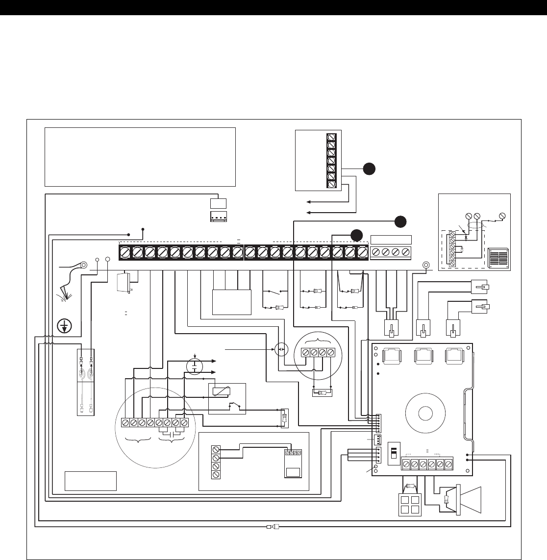
FIGURE 1 Suggested UL Household Burglar Alarm and/or Fire (ƒƒ) Alarm Hookup
ZX440F Wiring Diagram
ZX440F WIRING DIAGRAM
+12V NEG TG+ TG - COM NC NO
MPI-206
TO TERMINAL 10
TO TERMINAL 20
OPTIONAL - When relay is required
PGO1
PGO1
OUT
(ZXCFM J4)
ZX440F
-
TO RJ-31X
LINE 2
TO RJ-31X
LINE 1
RED
BLUE
GREEN
STRAIN
RELIEF
POWER-LIMITED
EARTH
GROUND
YELLOW
BLACK
BLUE
WHITE
GREEN
PURPLE
ORANGE
ZXCFM
J1 J3
J2
CONTROL LINE 2
B1+ NEG
LINE 1
B1- B2+ B2- B3
J6
PGO1
OUT
NEG (
J5
)
OFF
NORM
J8
J7
BLK
WHT
GRN
RED
BELL DISCONNECT
SWITCH
GRAY
(
J4
)
J11
J10
3
SW NEG
GREEN
Enclosure
Door
Ground
Wire
UNIFIED
EARTH
GROUND
QUIESCENT CHARGE
CURRENT: 20mA.
Replacement: Every 3 - 5 years.
FLOAT BATTERY VOLTAGE:
13.6 - 13.8V
Max. current: 500mA.
WARNING
Internally Fused.
Do Not Short.
Do Not Connect
To A Switched
Receptacle.
TRANSFORMER
Basler BE 118250
18.0VAC
U.L. Class II 60Hz
I.C. Load Number 1
1500Ω (CR854)
(CONV ZONING)
AC XFMR 4
AUX12 5
BELL 6
2WS 7
NEG 8
DAT A 9
DAT B 10
KP+12 11
NEG 12
Z1/7 13
Z2/8 14
NEG 15
Z3/9 16
Z4/10 17
NEG 18
Z5/11 19
Z6/12 20
NEG
1 2
++--
POWER ALARM
CONTACTS
LISTED RATE OF RISE OR
FIXED TEMPERATURE THERMOSTAT
TO ANY ZONE DEFINED
AS 24-HOUR FIRE
POWER SUPERVISION UNIT
ESL MODEL 204-12/24V
CONTROL STATIONS
AND OTHER
PERIPHERALS
RED
BLACK
BROWN BROWN
1500Ω
1/2 WATT
N.O.
N.C. ZONE 1
1500Ω
1/2 WATT
N.C. ZONE 3
825Ω
1/4 WATT
1500Ω
1/2 WATT
N.C.
N.C. ZONE 11
ZONE 5
++
--
1500Ω (CR854)
(EOL DEVICE)
POWER
SMOKE DETECTOR
SENTROL 2-WIRE
MODELS
METHOD 1 METHOD 2
TIP RING T1 R1
RED
BLACK
WHITE
PG01
TEL
SUPV
J-3
SMOKE DETECTOR
SENTROL 4-WIRE
MODELS
+
-
To Bat. + On The Control
(2) 12V SEALED
LEAD ACID BATTERIES
BATTERY
A
BATTERY
B
To Bat. - On The Control
RED
RED
+
N.C. ZONE 9
825Ω
1/4 WATT
+-
D1 D2
MOTION
DETECTOR
MODEL CR853 - 825Ω E.O.L.
MODEL CR854 - 1500Ω E.O.L.
UL LISTED RESISTORS
EARTH
GROUND
CONNECTION OF BURGLAR ALARM INITIATING DEVICES
HCP-12SULC
POWER SUPPLY
1234
+
-
DO NOT CONNECT BURGLAR
ALARM INITIATING DEVICES TO
THE SAME POWER SOURCE AS
FIRE ALARM DEVICES
Yuasa B-1270
ADEMCO AB12M
GRADE A BELL
COMMERCIAL
-
+
POLARIZATION AND
NOISE SUPPRESSION
DIODE
CONNECTION OF UL COMMERCIAL
BURGLAR AUDIBLE
JUMPER
ALL WIRING
BETWEEN CONTROL
& BELL MUST BE IN
CONDUIT.
1500Ω (CR854)
(EOL DEVICE)
B3NEG 13
Z2/8
NOTE
Terminal 19 (Z6/12) is used by the ZXCFM. Do not connect any other wires,
equipment or EOLs to this terminal. Connect only the yellow wire from the
ZXCFM to this terminal.
Terminal 5 (BELL) is used by the ZXCFM. Do not connect any other wires,
equipment or EOLs to this terminal. Connect only the white wire from the ZXCFM
to this terminal.
CLASS II
POWER-LIMITED
1500Ω
EOL
1500Ω
EOL
CLASS II POWER-LIMITED

8
1, 2 AC Input Connect the appropriate UL Class II transformer using 18 gauge minimum 2
conductor wire. Do not exceed 50 feet. Use a T1850 transformer.
CAUTION: Do not short the terminals of the transformer together. This
causes the internal fuse to blow. The transformer must be connected to a
120 VAC, 24-hour outlet not controlled by a switch other than an approved
over-current protection device.
NOTE: For commercial fire applications, an F2600 transformer enclosure must
be installed prior to connection of the primary power source. The AC power
wiring must be routed through dedicated conduit and a dedicated enclosure
knockout. It may not be intermixed with any low voltage power limited field
wiring per NFPA 70.
3 Switched Negative (-) Current limited 100 mA terminal. Negative connection for 4-wire smoke
detectors, glass break detectors, and devices requiring resettable power.
4 Auxiliary Power (+)12 VDC 500 mA continuous power. Overcurrent protected at 1.35 amps
(PTC4). Used for powering motion detectors, 4-wire smoke detectors, glass
break detectors, and other accessories.
CAUTION: Use terminals 4 and 10 when calculating total current drain.
5 Supervised Bell Output (+)12 VDC. Combined alarm current should not exceed 1.5 amps. Overcurrent
protected at 1.85 amps (PTC2). Terminal 5 is connected to the ZXCFM and the Bells
and their EOLs are connected off of the ZXCFM. Do not connect anything else to
terminal 5.
6 Two Wire Smoke (Zone 30) (+)12VDC of two-wire smoke detectors connected to this terminal. A 1500
(power-limited) Ohm EOL resistor (CR854) must be connected between terminals 6 and 7
regardless of whether a two-wire smoke detector is used or not. The maximum
series resistance is 30 Ohms. The maximum voltage is 13.85 VDC. The maximum
number of detectors is 20.
7, 11 Common Negative BLACK WIRE - (-)12 VDC. Negative connection for Control Stations, zone
expander, printer interface, ODMs, 2-wire smoke detectors, motion detectors, and
other devices.
8 Local Data Bus In (A) GREEN WIRE - Connection for Control Stations, zone expander, printer
interface and ODMs. Use 22 guage wire up to 1000 ft. Use 18 guage wire up to
2000 ft.
9 Local Data Bus Out (B) WHITE WIRE - Connection for Control Stations, zone expander, printer
interface and ODMs. Use 22 guage wire up to 1000 ft. Use 18 guage wire up to
2000 ft.
10 Control Station Power RED WIRE - (+)12 VDC 500 mA continuous power connection for Control
Stations, zone expander, printer interface and ODMs. Overcurrent protected at
1.85 amps (PTC4).
CAUTION: Use terminals 4 and 10 when calculating total current drain.
12 Zone 1/7 Loop (+)
13 Zone 2/8 Loop (+)
14 Common Negative
15 Zone 3/9 Loop (+)
16 Zone 4/10 Loop (+)
17 Common Negative
18 Zone 5/11 Loop (+)
19 Zone 6/12 Loop (+)
20 Common Negative
TIP Incoming Telephone Line GREEN wire from RJ-31X direct connect telephone cord.
RING Incoming Telephone Line RED wire from RJ-31X direct connect telephone cord.
T1 House Phone Connection BROWN wire from RJ-31X direct connect telephone cord.
R1 House Phone Connection GRAY wire from RJ-31X direct connect telephone cord.
PGO1 Programmable Output 1 PGO1 is connected to the ZXCFM.
TEL SUPV Telephone Supervision TEL SUPV is connected to the ZXCFM.
TERMINAL FUNCTION DESCRIPTION
ZX440F Terminal Descriptions
Each loop requires a 1500 Ohm end-of-line resistor (P/N CR854) for the primary
zone, and an 825 Ohm end-of-line resistor (P/N CR853) for the secondary zone.
A common negative is shared among all zones. The need for end-of-line resistors
may be eliminated on all Burglar defined zones through programming. See
Figure 1 for “2 in 1” Zoning™ wiring examples. Terminal 19 (Zones 6/12) is
connected to the ZXCFM for Phone Line Monitor and Ground Fault Monitor. Do
not connect anything else to terminal 19.
(power-limited)
(power-limited)
(power-limited)
ZX440F TERMINAL DESCRIPTIONS

9
J1 Phone Interconnect Phone connection to control panel.
J2 Phone Line 2 RJ-31X connection.
J3 Phone Line 1 RJ-31X connection.
J4 PGO1 Output +12 VDC, 40 mA programmable output. (See Figure 1).
J5 NEG Negative connection for PGO1.
J6 Panel Interconnect Seven pin connection to panel. Provides AC Power, Bell Monitor, Phone Line
Monitor, Ground Fault Monitor, Earth Ground, Phone Line Control, Bell and PGO1
Control and Sounder Control.
J7 Data Bus Four-wire Data Bus connection for devices (NEG, DATA A, DATA B, +12 VDC).
500 mA continuous power, overcurrent protected at 0.9 Amps (PTC1).
J8 Data Bus Interconnect Four-wire Data Bus connection to panel.
J10 Battery In Connection to battery.
J11 Battery Out Connection to (+) RED battery lead on control.
B1+ Fire Bell 1 (+)12 VDC. Alarm current should not exceed 0.5 Amps. Overcurrent protected
at 0.9 Amps (PTC2). A 1500 Ohm EOL resistor (CR854) must be connected
between terminals B1+ and B1-; otherwise a bell output fault will occur. The
Bell Disconnect switch will disable the bell and cause a bell fault.
B1- Fire Bell 1 Neg (-) 12 VDC. Negative connection for Fire Bell 1.
B2+ Fire Bell 2 (+)12 VDC. Alarm current should not exceed 0.5 Amps. Overcurrent protected
at 0.9 Amps (PTC7). A 1500 Ohm EOL resistor (CR854) must be connected
between terminals B2+ and B2-; otherwise a bell output fault will occur. The Bell
Disconnect switch will disable the bell and cause a bell fault.
B2- Fire Bell 2 Neg (-) 12 VDC. Negative connection for Fire Bell 2.
B3 Other Bell (+)12 VDC. Alarm current should not exceed 0.5 Amps. Overcurrent protected
at 0.9 Amps (PTC8). Unsupervised, an EOL resistor is not required.
NEG NEG (-) 12 VDC. Negative connection for Other Bell.
CONN FUNCTION DESCRIPTION
ZXCFM Connection Descriptions
ZXCFM CONNECTION DESCRIPTIONS
10
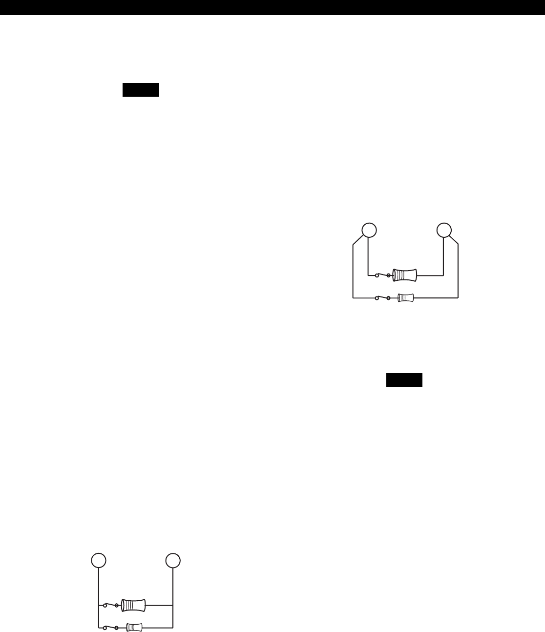
Method 2 wires two separate zone loops back into
one set of terminals. The panel recognizes each
loop independently because two different EOL re-
sistor values are used to differentiate between the
Primary Zone (1500 Ohm 1/2 Watt) and the Sec-
ondary Zone (825 Ohm 1/4 Watt). This method
provides two zones with one set of terminals and is
ideal for pre-wire or already installed wiring.
Figure 3 “2 in 1” Zoning™ Wiring - Method 2
The resistors in Figure 2 & 3 are 1%
values to maintain proper loop resis-
tance values. If replacements are re-
quired, please refer to the manufac-
turer for correct replacements. The
1500 ohm resistor is color coded
Brown•Green•Black•Brown•Brown.
The 825 ohm resistor is color coded
Gray•Red•Green•Black•Brown.
All zones sense five different voltage levels enabling
one zone to act as two. Troubleshooting is simple
using just a voltmeter at the control. The control
monitors the voltage level across the zone and uses
the voltage levels in Table 1 to determine whether
the zone is normal, open, or shorted.
If a Normally Open Device is used with
“2 in 1” Zoning™, a short will occur
across both zone loops when that de-
vice goes into alarm. It is recom-
mended that these types of devices
be used with Conventional Zone wir-
ing only. This type of wiring is not suit-
able for fire alarm initiating circuits.
The Sentrol ZX440F Security Control introduces an
all new method of wiring zones that saves both time
and wire costs. “2 in 1” Zoning™ allows the in-
staller to wire two separate zones in parallel into one
set of terminals.
Each zone is uniquely identified by its end-of-line re-
sistor. The Primary Zone (zones 1-6) in each termi-
nal is identified by a 1500 Ohm EOL resistor. The
Secondary Zone (zones 7 - 12) is identified by an
825 Ohm EOL resistor. The Primary and Secondary
zones operate as two independent zones to provide
separate reporting, programming, and displays. Each
zone is fully programmable as described in Installer
Level Programming - Zone Data Descriptions. The
zones are for Form A, Form B, or Form C sensors.
Maximum total loop wire and contact resistance
(not including EOL) must not exceed 100 Ohms
for the loop to function properly.
There are two methods of wiring for “2 in 1” Zon-
ing™. Method 1 wires one zone loop back to the
control while a second zone loop is added in parallel
off the first. This method may be employed in sys-
tem retrofits, system expansions, or just simply to
save wire cost and labor.
Figure 2 “2 in 1” Zoning™ Wiring - Method 1
NOTE
Secondary Zone
825Ω 1/4W
1500Ω 1/2W
Primary Zone
Secondary Zone
825Ω 1/4W
1500Ω 1/2W
Primary Zone
“2 in 1” Zoning™
NOTE
“2 in 1” Zoning™

11
Primary Zone and Secondary Zone Infinite Ohms 5.24 - 8.25 V
Open Contacts; Loop Cut or Open
Secondary Zone Open Contact, 1500 Ohms 4.24 - 5.23 V
Primary Zone Normal
Primary Zone Open Contact, 825 Ohms 3.24 - 4.23 V
Secondary Zone Normal
Primary Zone and Secondary Zone 825 Ohms in parallel with 2.00 - 3.23 V
Normal 1500 Ohms = 532 Ohms
Primary Zone and Secondary Zone 0 Ohms 0 - 1.99 V
Shorted
CONDITION NOMINAL LOOP RESISTANCE VOLTAGE READING
TABLE 1 “2 in 1” Zoning™ Troubleshooting Chart
“2 in 1” Zoning™
12
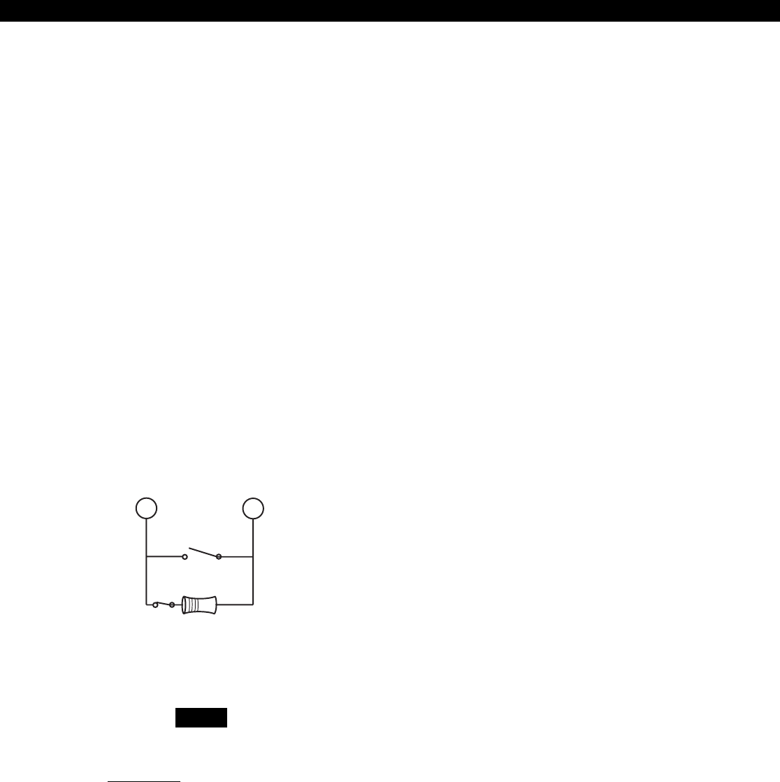
Class ‘B’ End-Of-Line Resistor
Supervised Zones
A Class ‘B’ zone must be supervised with a 1500
Ohm 1/2 Watt end-of-line resistor (P/N CR854). This
resistor should be installed in series at the furthest
point from the control. This configuration must be
used whenever both Form A and Form B devices are
connected and provides a high degree of protec-
tion against compromise or tampering. The control
monitors the voltage level across the Primary zone
and uses the Primary zone voltage levels in Table 1
to determine whether the zone is normal, open, or
shorted. The operation of a zone is programmable
as described in Installer Level Programming - Zone
Data Descriptions. Maximum total loop wire and
contact resistance (not including EOLs) must not
exceed 100 Ohms for the loop to function prop-
erly. The 1500 Ohm EOL resistor is optional for
Form A connections but is required for Form B.
Figure 4 Conventional Zone Wiring Method
For UL Listed systems, EOL Supervi-
sion is required.
1500Ω 1/2W
Primary Zone
Normally
Open
Normally
Closed
Non-Supervised Closed Circuit
Loop (No EOL Resistor
Supervision)
The EOL resistor is not required on Burglar zones. A
conventional closed circuit loop may be connected
directly to a primary zone and the zone will have
either a short or an open condition. See Installer Level
Programming - Zone Data Descriptions for program-
ming an unsupervised zone. Fire zones may not be
installed as unsupervised. Only Burglar defined
zones may be wired non-supervised. “2 in 1” Zon-
ing™ is not allowed.
Conventional Methods of Wiring
NOTE
CONVENTIONAL WIRING
13
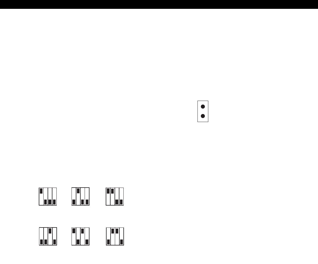
Control Station Addressing and Supervision
LED Control Stations
These Control Stations have a jumper on the circuit
board to set the address. To change the address of
the Control Station #1 to Control Station #2, remove
JP2 (see Figure 6).
4
1234
5
1234
6
1234
1
1234
2
1234
3
1234
ON
OFF
ON
OFF
ON
OFF
ON
OFF
CONTROL STATION ADDRESSING AND SUPERVISION
All Control Stations are shipped from the factory as
Control Station #1. They may be set to other ad-
dresses as described below.
A supervised Control Station is reported as missing
when the system fails to get any response from it.
In order to maintain supervision, each supervised
Control Station must have its own unique address.
SSD, LCD, and VFD Control
Stations
These Control Stations have a four position DIP
switch on the circuit board to set the address. To
change the address, the DIP switch setting must be
positioned according to Figure 5.
Figure 5 Control Station DIP Switch Settings
Figure 6 LED Control Station Jumper
JP2
Remove JP2 for keypad 2
14
Clearing Trouble Messages
Once the system is up and running, trouble condi-
tions may occur. Most trouble conditions are cleared
automatically when the condition that initiated the
trouble is restored or is eliminated. Three trouble
conditions (Memory Error, Smoke Trouble and Miss-
ing Keypad) may be cleared manually by pressing
and holding the Clear key for three seconds (until
two beeps are heard). This action is also required to
turn off the Duress output after it has been activated
and to cause an “Installer Off Premises” event (see
Operating the System - Installer On Premises).
Control Station Troubleshooting
CONTROL STATION TROUBLESHOOTING
If a Control Station is incorrectly wired, it will not
accept keystroke entries. The following symptoms
may appear:
from Common Negative (Terminal 7 or 11) to Data A (Terminal 8) ~ 8.7 VDC
from Common Negative (Terminal 7 or 11) to Data B (Terminal 9) ~ 3.5 VDC
from Common Negative (Terminal 7 or 11) to Control Station Power (Terminal 10) ~13.8 VDC
The nominal voltage at the control should measure
as follows:
TERMINAL VOLTAGE
A Bell 1 Silenced or Bell 2 Silenced trouble condition
may only be cleared by performing a smoke reset
operation.
No Control Station LED’s or display Black or Red Wire removed or cut
No response from key presses Green Wire removed or cut or two supervised
Control Stations at the same address
LED’s flash and may display “No Communication White Wire removed or cut
From Control” code Green/White Wires reversed
Green & White Wires shorted together
SYMPTOM CONDITION
15
12 VDC Outputs
12 VDC AND ADDITIONAL OUTPUTS
The ZX440F control provides one switched nega-
tive output, one Control Station power output, one
auxiliary power output, and one 2-wire smoke power
terminal. The ZXCFM on a ZX440F provides three
bell outputs and one programmable low current
output (PGO1). (See Figure 1).
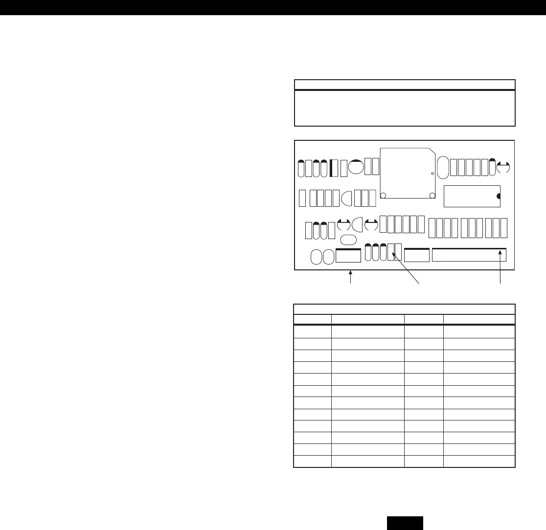
Additional Outputs
Additional outputs can be added with the ZXODM
Output Driver Modules. Each module receives its
data from the local data bus and provides ten addi-
tional programmable outputs. The outputs provide
+12 VDC on activation and must be limited to 40
mA of current draw. ODM1 has 10 unique outputs.
ODM2 also has 10 unique outputs.
The ODMs may be addressed as ODM1 or ODM2.
You may use multiple ODMs at a given address pro-
vided that power restrictions are followed. The
ODMs come defaulted from the factory as ODM1.
To change from ODM1 to ODM2, remove power,
cut resistor R29, and re-apply power. Connect the
ODMs to the control as shown in Figure 7. Use the
twelve (12) wire cable provided with the ODMs for
the outputs as shown.
Output conditions can be programmed as one of
many conditions. Refer to Installer Level Program-
ming - Output Definitions Description for program-
ming information and restrictions.
A ZXODM may be mounted in the control enclo-
sure using the stand-offs provided in the ZEM/ODM
mounting hardware pack (P/N 13000515), as shown
in Figure 22.
Data bus connection Remove for ODM #2 J3 Connector
RED Connect to Control terminal 10
GREEN Connect to Control terminal 8
WHITE Connect to Control terminal 9
BLACK Connect to Control terminal 7
D10
C11
D5
D4
C10
Q2
D3
ACTIVE
R19
R18
R21
C7
R14
R13
R27
R12
R15
R20
Q1
D2
C6
D1
R16
C4 U2
V3 V2
V1
J2
++
D9
D7
D6
R29
R28
C5
R25
R23
R22
R24
R26
C3
J1 J3
ASSEMBLED
IN USA
OUTPUTS
12V AB NEG 123
45678910
NEG 12V
R2
R3
R4
R5
R6
R7
R8
R9
R10
R11
PC BOARD
MADE IN (USA)
U4
U1Y1 C2
+
C8
R17
C9
C1
R1
D8
HICKORY, NC
60821484 REV A
COPYRIGHT 1996
SENTROL
CONTROLS GROUP
DATA BUS CONNECTION
1 Tan 13 Burglar
2 Pink 3 Fire
3 Gray 14 Holdup
4 Violet 15 Auxiliary/Medical
5 Yellow 19 Arm AWAY
6 Orange 31 Chime
7 Blue 18 Ready
8 Dk Brown 25 Pre-Alarm
9 Green 34 Lamp
10 White 39 Access
NEG Black
12V Red
J3 CONNECTIONS
OUTPUT WIRE COLOR DEFAULT DESCRIPTION
The outputs on this module have lim-
ited transient immunity and should
not leave the enclosure.
Figure 7 ZXODM Wiring Diagram
NOTE
16
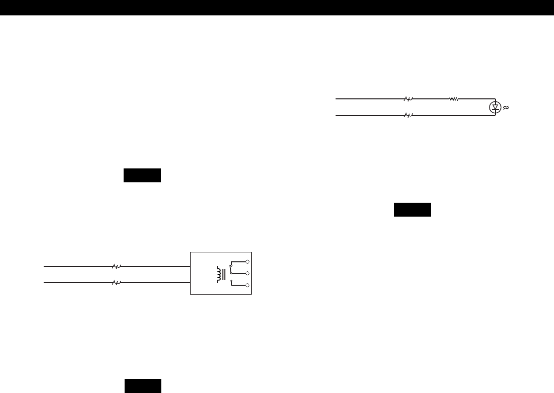
Outputs may be wired to indicator devices or re-
lay module triggers (MPI-206) provided the 40 mA
current draw condition is not exceeded. Figure 8
shows a wiring example for a relay to ODM 1
Output 2. Figure 9 shows a wiring example of
ODM 1 Output 1 to trigger an LED.
Connection to the ODM is only per-
mitted in residential fire and all bur-
glary applications.
Do not exceed 250 mA of total cur-
rent through the Red (+12V) and
Black wires (Negative) of the twelve
wire cable. Add 18 gauge wire from
the appropriate control panel termi-
nals for total current drains in excess
of 250 mA.
The LED & 470 Ohm current limiting
resistor shown in Figure 9 are not sup-
plied.
TAN WIRE
BLACK WIRE 470Ω
Connects to J3 (part of 12-wire cable)
Output 1
Neg
PINK WIRE
BLACK WIRE
Connects to J3 (part of 12-wire cable)
TRIG +
NEG
N.C.
COM
N.O.
+12V on Trig. Input
connects common to
N.O. terminals
Output 2
Neg
FIGURE 8 Output Connected to a Relay
NOTE
FIGURE 9 Output Connected to an LED
NOTE
12 VDC AND ADDITIONAL OUTPUTS
NOTE

17
ZONE ON-BOARD ZXP ZONE ZEM ZONE
1 On-Board Zone 1 Primary
2 On-Board Zone 2 Primary
3 On-Board Zone 3 Primary
4 On-Board Zone 4 Primary
5 On-Board Zone 5 Primary
6 On-Board Zone 6 Primary
7 On-board Zone 1 Secondary
8 On-Board Zone 2 Secondary
9 On-Board Zone 3 Secondary
10 On-Board Zone 4 Secondary
11 On-Board Zone 5 Secondary
12 On-Board Zone 6 Secondary
13 ZXP1 Zone 1 Primary ZEM1 Zone 1
14 ZXP1 Zone 2 Primary ZEM1 Zone 2
15 ZXP1 Zone 3 Primary ZEM1 Zone 3
16 ZXP1 Zone 4 Primary ZEM1 Zone 4
17 ZXP1 Zone 5 Primary ZEM2 Zone 1
18 ZXP1 Zone 6 Primary ZEM2 Zone 2
19 ZXP1 Zone 7 Primary ZEM2 Zone 3
20 ZXP1 Zone 8 Primary ZEM2 Zone 4
21 ZXP1 Zone 1 Secondary ZEM3 Zone 1
22 ZXP1 Zone 2 Secondary ZEM3 Zone 2
23 ZXP1 Zone 3 Secondary ZEM3 Zone 3
24 ZXP1 Zone 4 Secondary ZEM3 Zone 4
25 ZXP1 Zone 5 Secondary ZEM4 Zone 1
26 ZXP1 Zone 6 Secondary ZEM4 Zone 2
27 ZXP1 Zone 7 Secondary ZEM4 Zone 3
28 ZXP1 Zone 8 Secondary ZEM4 Zone 4
29 ZXP1 2-Wire Smoke Zone
30 On-Board 2-Wire Smoke Zone
Expansion Zones
Zones 13-28 are expansion zones. They may reside
on any zone expansion device (ZXEXP or ZEM).
Assignment of these zones to expansion devices is
done through programming (see Installer Level Pro-
gramming - Zone Data Descriptions).
The options available for all zones are described in
the table below.
EXPANSION ZONES
TABLE 2 ZX440F Zone ID Assignments
18
POWER-LIMITED
This module provides an additional 8 zones for the
ZX440F Control. If “2 in 1” Zoning™ is desired,
this module provides 16 zones. All zones are fully
programmable (see Installer Level Programming -
Zone Data Descriptions). The Zone Expander termi-
nals map into zones on the control as shown in Table
2. An additional Two-Wire Smoke loop is also pro-
vided on this module (Zone 29). This loop follows
the same wiring restrictions as Terminal 6 on the
ZX440F control (max. 10 detectors). Fast zones may
not be used on the Zone Expander Module.
Ten power-limited programmable outputs are avail-
able on the ZXEXP Zone Expander Module. These
outputs are identical to the 10 outputs on ODM2.
Connect the outputs to J2 on the ZXEXP in the same
manner as J3 on the ZXODM. When using the out-
puts on this module, make sure all restrictions men-
tioned in the ZXODM section for power and nega-
tive are observed. The outputs have limited tran-
sient protection and should be properly protected
(buffered by relays, etc.). They should be mounted in
a suitable enclosure such as an EB1511 or EX1414 (part
# 13000421).
1500
Ω
** ** **
+12 AB NEG
J1
CONNECT TO DATA BUS ONLY
+12V - Red
DATA A - Green
DATA B - White
NEG - Black
ACTIVE LED
* TERMINATE PRIMARY ZONES WITH 1500 OHM RESISTORS. TERMINATE SECONDARY ZONES WITH 825 OHM
RESISTORS. IF USING “2 in 1” ZONING™ OR FOUR WIRE SMOKE CIRCUIT, SEE INSTALLATION MANUAL 64812692
Z1 Z2
NEG(-)
Z3 Z4
NEG(-)
Z5 Z6
NEG(-)
Z7 Z8
NEG(-)
SMK
NEG(-)
PROGRAMMABLE OUTPUTS
OUTPUTS ARE 12 VOLT DC • 40 MILLIAMPS MAX.
1 2 3 4 5 6 7 8 9 10 (-) (+)
ZXEXP ZONE EXPANDER
64600299C
MOOSE
a product of sentrol, inc
* *
ZXEXP ZONE EXPANDER MODULE
ZXEXP Zone Expander Module
Installation
1. Remove the plastic lid from the ZXEXP Zone
Expander Module. Choose a suitable mounting
place and mount the module with the two
screws provided. It is recommended that the
module be placed in a suitable enclosure like the
EB1511 for additional environmental protection.
2. Connect the ZXEXP to the ZX440F local data
bus. For a UL Household Fire System, the ZXEXP
must be mounted within 500 ft. of the ZX440F
and the maximum Smoke Zone resistance is 20
Ohms.
3. Wire initiating devices to the appropriate zone
terminals on the ZXEXP module (see Table 2).
Follow the same guidelines for “Hardware Zone
Wiring” as completed for the control zones.
4. Use the 12 wire cable to connect outputs as de-
scribed in the ZXODM section.
5. The “Active” LED will flash to indicate the ZXEXP
is communicating with the control.
RED Connect to Control terminal 10
GREEN Connect to Control terminal 8
WHITE Connect to Control terminal 9
BLACK Connect to Control terminal 7
DATA BUS CONNECTION
FIGURE 10 ZXEXP Zone Expander Module
POWER-LIMITED
POWER-LIMITED
19
FIRE ZONE MODULES
Fire Zone Modules
ZEM Zone Expansion Module
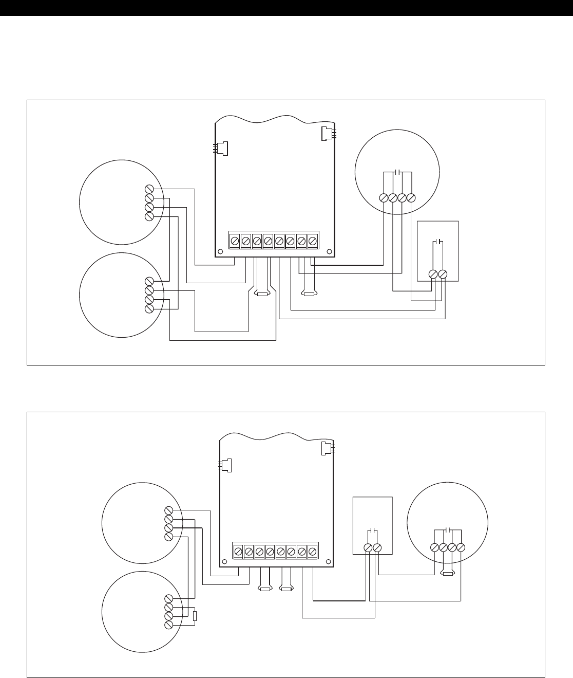
The ZX440F provides an option for adding Class A
and Class B Fire zones. These zones may be con-
nected to ZEM Fire Zone Expansion Modules. There
are three models of ZEMs available:
2502-ZEM Two Class B Zones
2502A-ZEM Two Class A Zones
2504-ZEM Four Class B Zones
Refer to the ESL 2504/2502/2502A-ZEM Installation
Instructions 64812713B for additional information.
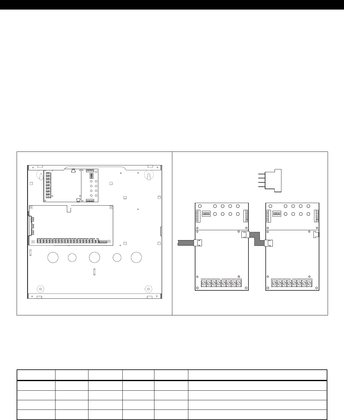
A ZEM may be mounted in a ZX440F control enclo-
sure as shown in Figure 11. A ZEM may also be
mounted in an EX1414 enclosure (P/N 13000421).
Always use a ZEM/ODM mounting hardware pack
(P/N 13000515). Connect the ZEM to the ZX440F
local data bus using one of the ZEM’s two data bus
connectors. The second data bus connector may be
used to connect another ZEM to the system.
FIGURE 12 ZEM Module Connection
ZEM # S1 S2 S3 S4 ZONES
1 ON OFF OFF OFF 13 & 14 OR 13 - 16
2 OFF ON OFF OFF 17 & 18 OR 17 - 20
3 ON ON OFF OFF 21 & 22 OR 21 - 24
4 OFF OFF ON OFF 25 & 26 OR 25 - 28
TABLE 3 ZEM Address Switch Settings
Up to four ZEMs may be connected to the system.
Set the address switches on a ZEM to provide the
following zones:
Be sure that no two ZEMs have the same address
settings.
B+ B- B+ B- B+ B- B+ B-
ZONE 1 ZONE 2 ZONE 3 ZONE 4
TB1
POWER ALARM
ZONE 1
TRBL
ALARM
ZONE 2
TRBL
ALARM
ZONE 3
TRBL
ALARM
ZONE 4
TRBL
B+ B- B+ B- B+ B- B+ B-
ZONE 1 ZONE 2 ZONE 3 ZONE 4
TB1
POWER ALARM
ZONE 1
TRBL
ALARM
ZONE 2
TRBL
ALARM
ZONE 3
TRBL
ALARM
ZONE 4
TRBL
ZEM 1 ZEM 2
Four
Wire
Cable
Four Wire
Cable to
Control
Panel
Control Term 10 (RED) 12V
Control Term 8 (GREEN) Data A
Control Term 9 (WHITE) Data B
Control Term 7 (BLACK) Neg
Data Bus
Connector Pins
FIGURE 11 ZEM Mounting
B+ B- B+ B- B+ B- B+ B-
ZONE 1 ZONE 2 ZONE 3 ZONE 4
TB1
POWER ALARM
ZONE 1
TRBL
ALARM
ZONE 2
TRBL
ALARM
ZONE 3
TRBL
ALARM
ZONE 4
TRBL
3
SW NEG
AC XFMR 4
AUX12 5
BELL 6
2WS 7
NEG 8
DAT A 9
DAT B 10
KP+12 11
NEG 12
Z1/7 13
Z2/8 14
NEG 15
Z3/9 16
Z4/10 17
NEG 18
Z5/11 19
Z6/12 20
NEG
1 2
TIP RING T1 R1
ZX400/ZX410
ZEM
ZX440F
20
FIRE ZONE MODULES
Heat Sensor
Zone 2 is shown with 2-wire
heat detectors and pull stations,
wired in Class A (Style D)
Zone 1 is shown with
2-wire detectors,
wired in Class A (Style D)
CR852
1.8K EOL CR852
1.8K EOL
429C
++--++--
429C
B+ B- A+ A- B+ B- A+ A-
ZONE 1 ZONE 2
TB1
ZEM
(2502-A)
Zone 1 Zone 2
Databus
Connector
Databus
Connector
Pull Station
Zone 1 is shown with
2-wire detectors,
wired in Class B (Style B)
CR852
1.8K
EOL
CR852
1.8K
EOL
CR852
1.8K
EOL
Zone 4 is shown with 2-wire
heat detectors and pull stations,
wired in Class B (Style B)
Heat Sensor
Pull Station
CR852
1.8K
EOL
--
429C
++ -- ++
429C
B+ B- B+ B- B+ B- B+ B-
ZONE 1 ZONE 2 ZONE 3 ZONE 4
TB1
ZEM
(2504)
Zone 1
Zone 2
Zone 3
Zone 4
Databus
Connector
Databus
Connector
FIGURE 14 Class B Connection
FIGURE 13 Class A Connection
Connect initiating devices to the ZEM (see figures
below).

21
FIRE ZONE MODULES
Databus
Connector Databus
Connector
ZEM
B+
Zone 2
Zone 3
B- B+ B- B+ B- B+ B-
Zone 4
Zone 5
RELAY 1
NC
COM
NO
NC
COM
NO
NC
COM
NO
NC
COM
NO
RELAY 2
RELAY 3
RELAY 4
Optional
ZRM
TB1
ZONE 1 ZONE 2 ZONE 3 ZONE 4
POWER ALARM
ZONE 1
TRBL
ALARM
ZONE 2
TRBL
ALARM
ZONE 3
TRBL
ALARM
ZONE 4
TRBL
NORM
WT
DIS
SWT
NORM
WT
DIS
SWT
NORM
WT
DIS
SWT
NORM
WT
DIS
SWT
ZEM
Function Jumper
WT
NORM
DIS
SWT
NOTE
B+ B- B+ B- B+ B- B+ B-
ZONE 1 ZONE 2 ZONE 3 ZONE 4
TB1
POWER ALARM
ZONE 1
TRBL
ALARM
ZONE 2
TRBL
ALARM
ZONE 3
TRBL
ALARM
ZONE 4
TRBL
RELAY 1
NC
COM
NO
NC
COM
NO
NC
COM
NO
NC
COM
NO
RELAY 2
RELAY 3
RELAY 4
ZEM
ZRM
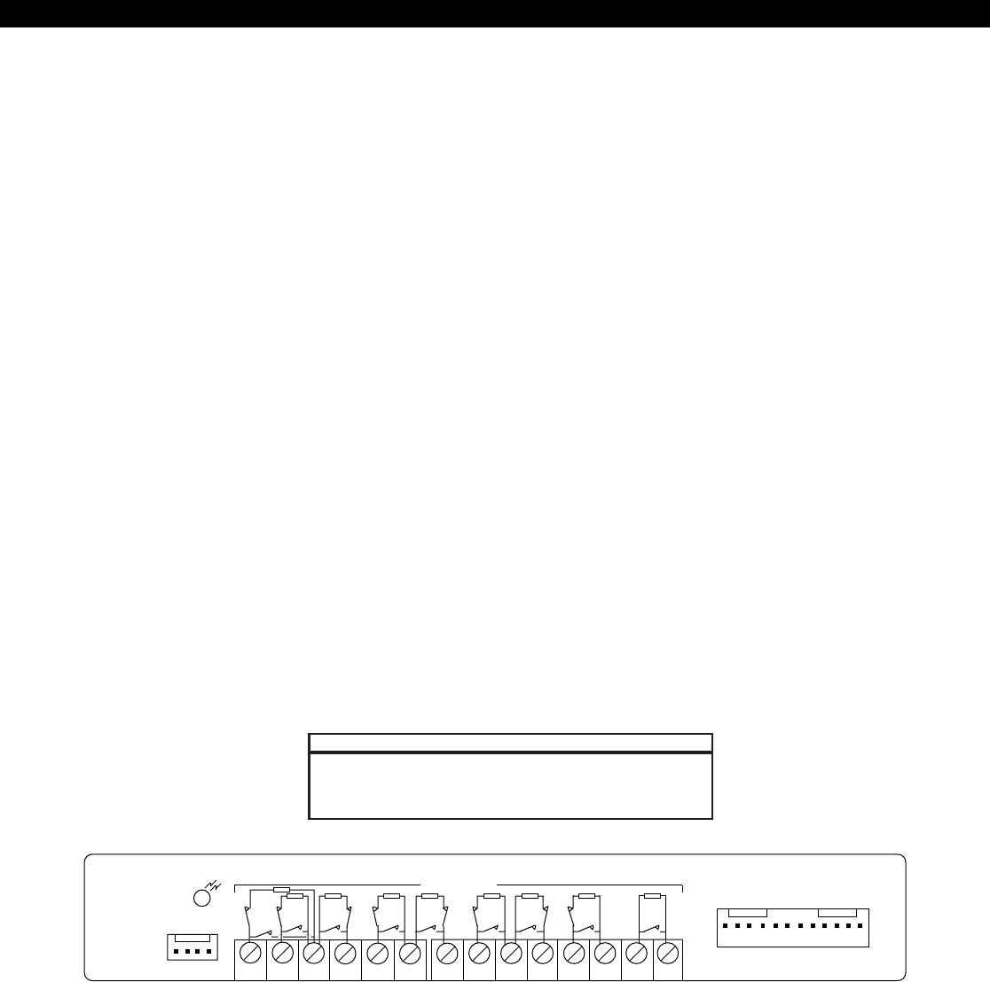
FIGURE 15 ZEM Function Jumpers
FIGURE 16 Mounting ZRM to ZEM Module
ZRM Zone Relay Module
The ZRM Zone Relay Module is a zone follower with
a relay following its corresponding zone on a ZEM.
A ZRM plugs directly into a ZEM and only requires
wiring the terminals labeled NO, COM, and NC.
Each relay has dry, Form “C” contacts rated 2A @
30 VDC resistive.
Circuits connected to a ZRM must be
power-limited.
Ensure that the Function Jumper for each zone is
always in the NORM position.

22
ZXCFM COMMERCIAL FIRE MODULE
ZXCFM Commercial Fire Module
UL 864 Compliance
The ZX440F with a properly installed ZXCFM Fire
Module complies with the following UL Control Unit
Classifications (3.6) definitions under UL 864 Stan-
dard for Control Units for Fire Protective Signaling
Systems:
• NFPA 72 - Local Protective Signaling Systems and
Central Station Systems
If a Printer Interface and/or Zone Expander(s) are
used with the Commercial Fire System, they must
be installed within 20 feet of the control unit with
all interconnections in conduit.
Minimum System Configurations
• One ZX440F Control/Communicator
- ZX400 Control Board
- ZXCFM Fire Module
- EX1414-RED Enclosure
- Dual Battery Harness
• One ZXLCD Control Station
• Two 12 VDC, 7 Ah sealed lead acid batteries
• One T1850, 18 VAC, 50 VA Transformer
• One F2600 Transformer Enclosure
• One UL Listed Smoke Detector (see List of Com-
patible Accessories)
• One UL Listed Fire Audible Signaling Device
Maximum System Configurations
• One ZX440F Control/Communicator
- ZX400 Control Board
- ZXCFM Fire Module
- EX1414-RED Enclosure
• One ZXLCD Control Station
• Two 12 VDC, 17.2 Ah sealed lead acid batteries
• One CR862 dual battery harness
• One EB1511 Auxiliary Battery Enclosure
• One T1850, 18 VAC, 50 VA Transformer
• One F2600 Transformer Enclosure
• UL Listed peripheral devices including smoke
detectors and audibles must not exceed a com-
bined current drain of 450 mA (see List of Com-
patible Devices)
ZXCFK Fire Module Kit
The ZXCFK Fire Module Kit is designed to provide
the hardware necessary to upgrade a ZX410 to meet
the requirements for a UL Listed commercial fire sys-
tem per UL 864/NFPA 72 Local Protective Signaling
Systems and Central Station Systems.
ZXCFK Contents
• One ZXCFM Fire Module
• One dual battery harness
• Two ZXCFM battery leads
• One phone cable assembly
(Part Number 13000505)
• Four PCB Supports
• Four #6-32 x 3/8" mounting screws
• Two #6 x 1/4" hex heat sink screws
• Two output wire assemblies
• One T1850 18 VAC, 50 VA transformer
Upgrading a ZX410 With a ZXCFK
1. Before connecting the control to its external
power source, remove the ZXCFK components
from the packing material and inspect to ensure
that all components are present.
2. Disconnect battery. Remove power and replace
transformer with T1850 transformer.
3. Locate the (4) ZXCFM PCB Supports in the hard-
ware pack.
4. Press the supports into the enclosure, either from
the rear or from the front of the enclosure, in
the four square embossed holes (see Figure 18).
The snaps may be pressed into the holes from
the rear of the enclosure or installed from the
front by compressing the snap before insertion
into the hold.
5. Align the four holes in the ZXCFM printed cir-
cuit board with the four PCB supports.
6. Secure the ZXCFM to the enclosure using four
(4) #6-32 x 3/8" machine screws provided. Se-
cure the ZXCFM heat sink to the side of the enclo-
sure using two (2) #6 x 1/4" hex heat sink screws
provided.

23
ZXCFM COMMERCIAL FIRE MODULE
7. Make the following wire connections from the
ZXCFM (J6) to the ZX400 control panel (see Fig-
ure 1):
a. Orange wire to AC post D1
b. Purple wire to AC post D2
c. White wire to Bell (terminal 5)
d. Yellow wire to Z6/12 (terminal 19)
e. Blue wire to post TEL SUPV (TP1)
f. Black wire to post PGO1 (TP2)
g. Green wire to Earth Ground
8. Connect the phone cable assembly from the
ZX400 control panel to Telco jack (J1) on the
ZXCFM.
9. Connect the 4-wire cable (J8) on the ZXCFM to
the bus connector (J3) on the ZX400 control
board.
FIGURE 18 Installing the ZXCFM Fire Module to the ZX410 enclosure
3
SW NEG
AC XFMR 4
AUX12 5
BELL 6
2WS 7
NEG 8
DAT A 9
DAT B 10
KP+12 11
NEG 12
Z1/7 13
Z2/8 14
NEG 15
Z3/9 16
Z4/10 17
NEG 18
Z5/11 19
Z6/12 20
NEG
1 2
TIP RING T1 R1
ZX400/ZX410 ZXCFM
J1 J3
J2
CONTROL LINE 2
B1+ NEG
LINE 1
B1- B2+ B2- B3
J6
PGO1
OUT
NEG (
J5
)
OFF
NORM
J8
J7
BLK
WHT
GRN
RED
POWER-LIMITED
BELL DISCONNECT
SWITCH
(
J4
)
J11
J10
(4) PCB SUPPORTS
+
-
+
-
BATTERY B BATTERY A
To J10
On The ZXCFM
To Bat. -
On The Control
10. Connect two 7 Ah batteries with the dual bat-
tery harness provided. (See Figure 17). Connect
the (-) battery terminal to (J2) on the control using
the control battery lead. Connect the (+) battery
terminal to (J10) on the ZXCFM using a ZXCFM
battery lead. Connect (J1) on the control to (J11)
on the ZXCFM using the control battery lead
and the other ZXCFM battery lead.
FIGURE 17 Connection of the Dual Battery
ZX440F
Harness
24
AC Fail Delay 30 min 7 hours
Zone 6 Burglar Not Used
(Telco Monitor)
Zone 12 Burglar Not Used
(Ground Fault)
Phone Line 1 Enabled, Enabled
No Monitor with Monitor
Phone Line 2 Disabled Enabled
with Monitor
System Events 0 3
Phone No.
Comm Test Not 00 F2
Normal Report Code
Comm Test 00 F1
Report Code
Days Between 0 1
Comm Tests
ZXCFM COMMERCIAL FIRE MODULE
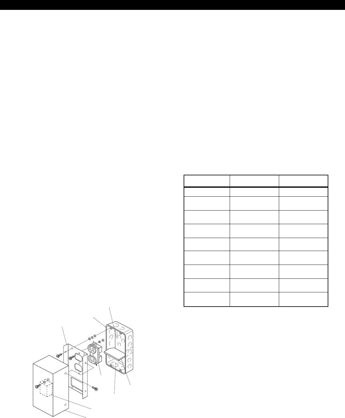
Installation of the F2600
Transformer Enclosure
The transformer enclosure ensures that the AC plug-
in transformer remains securely fixed to the AC wall
outlet. Before installing, disconnect primary power
source. Restore power only after the transformer con-
nection has been double-checked for accuracy.
1. Mount the gang box to the wall or supporting
structure.
2. Insert the gang box partition into the gang box.
The partition divides the gang box into two sec-
tions. The large section contains high voltage
wiring; the small section contains low voltage
wiring.
3. Punch out a conduit knockout in the high volt-
age side of the gang box. Route the 110 VAC
wiring through the knockout hole and into the
gang box. Connect the isolated 110 VAC wiring
to the duplex outlet.
4. Mount the duplex outlet to the cover plate and
the cover plate to the gang box.
5. Punch out a conduit knockout in the low volt-
age side of the gang box. Route the low voltage
wiring to the transformer.
6. Plug the transformer into the bottom outlet of
the duplex outlet. Secure the transformer to the
duplex outlet.
7. Attach the cover to the cover plate.
Low Voltage
Section
Transformer
Cover
Duplex
Outlet
Gang Box
Partition
Cover Plate
Gang Box
High Voltage
Section
Defaulting the Control for
Commercial Fire Alarm Use
If the ZXCFM is added to an existing ZX410 con-
trol, then the ZX410 control panel must be defaulted
in software programming for commercial fire use.
To default the control panel for commercial fire use:
1. Press 9 (Program)
2. Enter Installer Passcode
3. Select Option 6 (Default the Panel)
4. Select Option 1 (Commercial Fire)
5. Re-enter installer passcode to verify
The system default changes are:
PROGRAM
FUNCTION STANDARD
DEFAULT COMMERCIAL
FIRE
FIGURE 19 Transformer Enclosure
25
ZXCFM COMMERCIAL FIRE MODULE
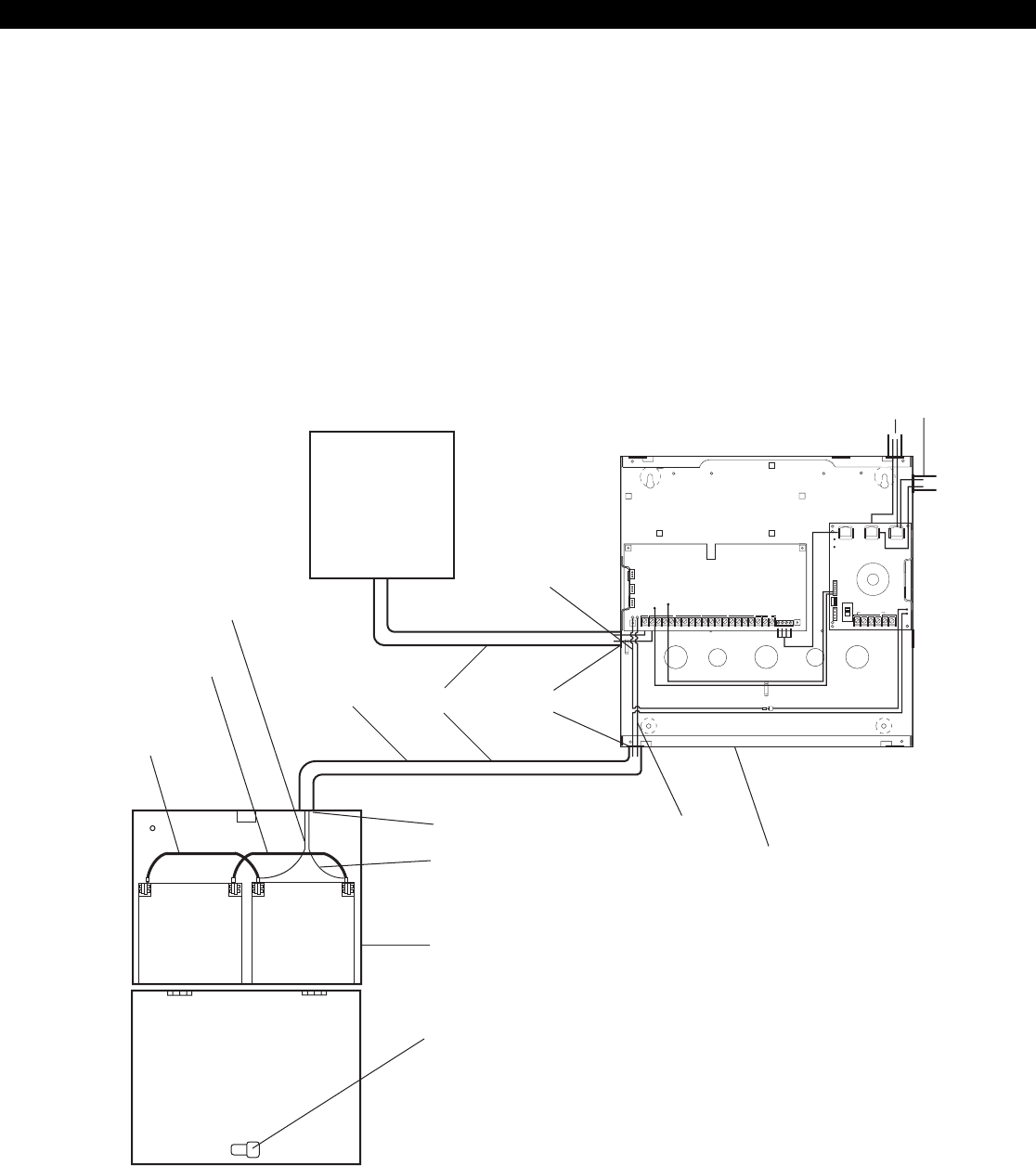
Optional Battery Configurations
In order to meet UL864 standby current require-
ments of 24 hours at 450 mA, a minimum of two 12
VDC, 7 Ah sealed lead acid batteries must be in-
stalled utilizing the dual battery harness as shown in
Figure 17. However, a single 12 VDC, 17.2 Ah sealed
lead acid battery may be used in place of the two 7
Ah batteries to obtain the same standby current us-
ing the CR862 Dual Battery Harness. See Figure 20
with Battery A only.
To increase standby current to 60 hours at 180 mA,
two 12 VDC, 17.2 Ah sealed lead acid batteries may
be installed in place of the two 12 VDC, 7 Ah batter-
ies. The CR862 Dual Battery Harness must be used
to connect the 17.2 Ah batteries to the control. The
EB1511 Auxiliary Battery Enclosure is required to
house the batteries. Additionally, all interconnections
must be run in conduit. Install the batteries as shown
in Figure 20.
FIGURE 20 Connection of the CR862 Dual Battery Harness and Power Conductor Routing
F2600
Red Wire
3/4" KnockoutsConduit
Non-Power
Limited
Black Wire
Control
Panel
Phone Lines
L1 and L2
(Power Limited)
Red Wire
32" Lg. To Panel
Black Wire
12" Lg.
Red Wire
12" Lg.
1/2" Knockout
Black Wire
32" Lg. To Panel
EB1511
Battery Enclosure
BATTERY B BATTERY A
Camlock
NOTES: 1) Route external AC and DC power wiring
through the knockouts as shown above.
2) Do not route any low voltage power
limited wiring through the same
knockouts or conduit as the AC/DC
power wiring. See NFPA 70 or UL 864.
3) Maintain a minimum of 1/4 inch
separation between Power Limited and
Non-Power Limited wiring.
CAUTION: OBSERVE POLARITY OF LOAD
+--
+
3
SW NEG
AC XFMR 4
AUX12 5
BELL 6
2WS 7
NEG 8
DAT A 9
DAT B 10
KP+12 11
NEG 12
Z1/7 13
Z2/8 14
NEG 15
Z3/9 16
Z4/10 17
NEG 18
Z5/11 19
Z6/12 20
NEG
1 2 TIP RING T1 R1
ZX400/ZX410
ZXCFM
J1 J3
J2
CONTROL LINE 2
B1+ NEG
LINE 1
B1- B2+ B2- B3
J6
PGO1
OUT
NEG (J5)
OFF
NORM
J8
J7
BLK
WHT
GRN
RED
POWER-LIMITED
BELL DISCONNECT
SWITCH
(J4)
J11
J10
D1 D2
ZX440F
26
ZXCFM COMMERCIAL FIRE MODULE
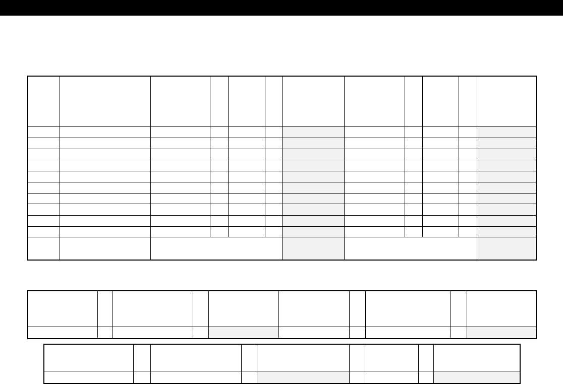
ITEM DESCRIPTION
STANDBY
CURRENT
PER UNIT
(AMPS)
QTY
TOTAL
STANDBY
CURRENT
PER ITEM
(AMPS)
TOTAL
ALARM
CURRENT
PER UNIT
(AMPS)
QTY
TOTAL
SYSTEM
ALARM
CURRENT
(AMPS)
TOTAL SYSTEM
STANDBY CURRENT (AMPS) TOTAL SYSTEM
ALARM CURRENT (AMPS)
X
X
X
X
X
X
X
X
X
X
=
=
=
=
=
=
=
=
=
=
X
X
X
X
X
X
X
X
X
X
=
=
=
=
=
=
=
=
=
=
REQUIRED
STANDBY
TIME
(HOURS)
TOTAL SYSTEM
STANDBY
CURRENT
(AMPS)
REQUIRED
STANDBY
CAPACITY
(AMP-HOURS)
REQUIRED
ALARM
TIME
(HOURS)
TOTAL SYSTEM
ALARM
CURRENT
(AMPS)
REQUIRED
ALARM
CAPACITY
(AMP-HOURS)
X= X =
REQUIRED BATTERY
CAPACITY
(AMP-HOURS)
OPTIONAL
FACTOR OF
SAFETY
TOTAL REQUIRED
CAPACITY
(AMP-HOURS)
REQUIRED ALARM
CAPACITY
(AMP-HOURS)
REQUIRED STANDBY
CAPACITY
(AMP-HOURS)
+=X
REQUIRED OPERATING TIME OF SECONDARY POWER SOURCE FROM NFPA 72 1-5.2.5:
STANDBY:__________ HOURS ALARM:_________ MINUTES X 1/60 = __________ HOURS
ZX440F Power Worksheet
27
ZXCFM COMMERCIAL FIRE MODULE
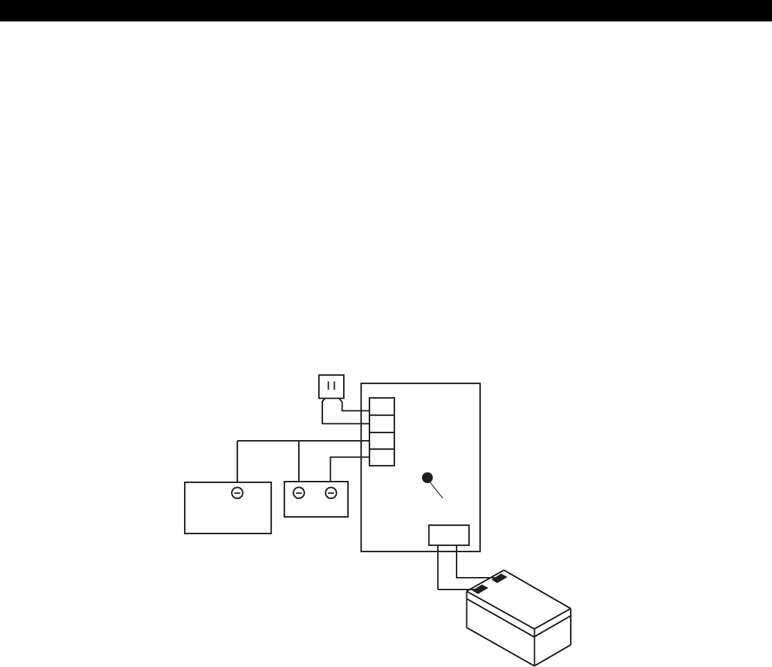
Auxiliary Power Supply Installation
To increase the available current supplied by the
ZXCFM, a HCP-12SULC Power Supply may be
added. Each HCP-12SULC supplies an additional 450
mA of current, utilizing at least one 12 Ah battery.
See Figure 21.
The HCP-12SULC Power Supply can provide a 12
VDC power output, with a current rating of 2.0 A
continuous, while the AC primary power source is
present. If the primary source is lost, the HCP-12SULC
electronically switches to the standby battery.
(-) (+)
Auxiliary Power
Supply Transformer
Peripheral
Device(s)
Control/
Communicator
BatteryCAUTION: Observe polarity of load
LED
Auxiliary
Power
Supply
AC
AC
(-)
(+)
1
2
3
4
+
-
The HCP-12SULC must not be connected to a load which exceeds 2.0A continuous demand.
When using this power supply on a listed system, a
duplex utility cover for the primary power outlet must
be installed. Install conduit or another listed race-
way between all connecting junction boxes and pro-
tective enclosures as shown.
Use only the battery and transformer as recom-
mended in the HCP-12SULC Installation Instructions
P/N 64812502. For information about the connec-
tion of additional batteries, see "Optional Battery
Configurations" earlier in this section.
FIGURE 21 HCP-12SULC Power Supply Installation
28
ZXCFM COMMERCIAL FIRE MODULE
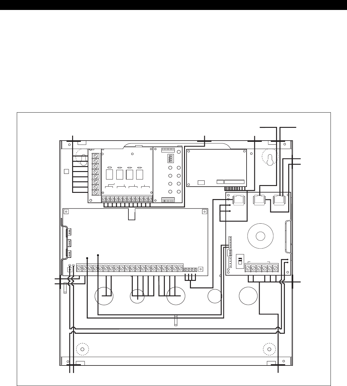
System Power Routing
Non-power limited fire alarm system wiring may be
installed using any of the methods permitted by Ar-
ticle 760 of the National Electrical Code (NEC), NFPA
70-1996, for non-power limited fire alarm (NPLFA)
circuits. See 760-21 to 760-31 of NFPA 70-1996.
The circuit conductors of power limited fire alarm
FIGURE 22 System Power Routing
B+ B- B+ B- B+ B- B+ B-
ZONE 1 ZONE 2 ZONE 3 ZONE 4
TB1
POWER ALARM
ZONE 1
TRBL
ALARM
ZONE 2
TRBL
ALARM
ZONE 3
TRBL
ALARM
ZONE 4
TRBL
RELAY 1
NC
COM
NO
NC
COM
NO
NC
COM
NO
NC
COM
NO
RELAY 2
RELAY 3
RELAY 4
3
SW NEG
AC XFMR 4
AUX12 5
BELL 6
2WS 7
NEG 8
DAT A 9
DAT B 10
KP+12 11
NEG 12
Z1/7 13
Z2/8 14
NEG 15
Z3/9 16
Z4/10 17
NEG 18
Z5/11 19
Z6/12 20
NEG
1 2
TIP RING T1 R1
ZX400/ZX410
ZEM
ZRM
J1 J3
OUTPUTS
12345 6 7 8 9 10 NEG 12V
ZXODM
TRANSFORMER
AC IN BELL
CIRCUITS
ZONE INITIATING CIRCUITS
TELCO IN
TELCO LINE 1
TELCO LINE 2
ZXCFM
J1 J3
J2
CONTROL LINE 2
B1+ NEG
LINE 1
B1- B2+ B2- B3
J6
PGO1
OUT
NEG (
J5
)
OFF
NORM
J8
J7
BLK
WHT
GRN
RED
POWER-LIMITED
BELL DISCONNECT
SWITCH
(
J4
)
BATTERY IN
D1 D2
ZONE INITIATING CIRCUITS
PGO1 & ODM OUTPUTS
ZRM OUTPUTS
J11
J10
ZX440F
circuits must be separated from non-power limited
fire alarm circuits and ordinary light and power cir-
cuits pursuant to the requirements of Article 760-54
of the NEC. Figure 22 below shows one method of
routing conductors that can be used to comply with
the required 1/4 inch separations.

29
ZXPTR Printer Interface Module
ZXPTR PRINTER INTERFACE MODULE
The optional ZXPTR Printer Interface Module con-
nects to the local data bus and can be used for print-
ing events in real-time or on command. This mod-
ule interfaces with any Centronics-style parallel
printer. Only one printer may be used per system.
Note that the printer connection is not supervised.
1. To install the ZXPTR, choose a suitable location,
but not more than 25 feet from the Centronics-
style parallel printer, following the wiring descrip-
tion in Figure 1.
2. Remove the cover and circuit board and mount
the base to an appropriate wall or desktop.
3. Attach the printer cable to the ZXPTR printer
port and affix with screws if desired.
4. Wire the local data bus to the terminals: +12V is
red; Data A is green; Data B is white; NEG is
Black.
5. Reinstall the circuit board and cover.
6. The “Active” LED will flash to indicate the ZXPTR
is communicating with the control.

30
Control Board
• Five (5) two-wire zones, each supervised with a
1500 Ohm end-of-line resistor. “2 in 1” ZoningTM
provides ten (10) fully programmable zones with
1500 and 825 Ohm resistors. Zones 6 & 12 are
dedicated to Telco Monitor and Ground Fault
Monitor and are not available. System expan-
sion to 26 fully programmable zones via Zone
Expander Module (ZXEXP).
• Fast zone loop response time: 80 msec (zones
1-5), 20 msec (zones 7-11).
• Two supervised, assignable, high current, Fire
Bell outputs via Fire Module (ZXCFM).
• One assignable, high current, alarm output via
ZXCFM.
• One programmable low current output (40 mA)
via ZXCFM.
• Trouble sounder via ZXCFM.
• Two supervised telephone lines via ZXCFM.
•Dedicated two-wire smoke detector zones on
control (zone 30) and zone expander (zone 29).
•Three (3) Control Station activated panic zones.
•Nominal current drain for control board only
126 - 154 mA.
•Watchdog microprocessor monitoring.
•Superior six (6) stage lightning/transient protec-
tion.
•One switched negative output (100 mA).
•Expandable to twenty-one (21) programmable
low current outputs via two output driver mod-
ules, and/or a zone expander.
•Continuous battery monitoring.
•Low voltage detection monitoring @ 11.3 volts
threshold.
•Automatic system shutdown if voltage falls be-
low 9.8V.
•Operating temperature range inside the enclo-
sure: 32˚F to 122˚F (0˚C to +50˚C).
•Two and four-wire smoke zones available.
•Control Station Programmable.
•Upload/Download via RPM/2 Pro.
•Loop response time: 320 msec (general purpose
hardwired zones), 1600 msec (two-wire smoke
zones).
SPECIFICATIONS AND FEATURES
Specifications And Features
Power Supply
• Fully regulated 13.8 volt 2.0 Amp supply avail-
able with an 18 VAC 50 VA transformer.
• Reverse polarity protection on battery inputs.
• Floating charging circuit: 13.8 volts DC.
Recommended Battery
•Two rechargeable 12 VDC 7 Ah sealed lead acid
batteries to meet the UL 864 and UL 985 Fire
requirement of 24 hour standby at 450 mA.
•Two rechargeable 12 VDC 17.2 Ah sealed lead
acid batteries to meet UL 864 Fire requirement
of 60 hour standby of 180 mA.
Transformer
•UL Listed Class II plug-in; 18 VAC 50 VA second-
ary; 120 V 60 Hz primary connected to 24-hour
unswitched outlet. Sentrol P/N T1850.
Enclosure
•EX1414F red enclosure.
Digital Communicator
•DTMF Touchtone™ or Rotary (pulse) dialing.
Rotary speed: 10pps, (selectable U.S. style 60%
break, 40% make or International style 66%
break, 33% make).
•Ringer equivalence: 0.0B.
•Transmission formats include: Contact ID, 20
and 40 baud Pulse Formats (3/1, 4/1, 4/2, Hexa-
decimal Reporting), Non-Telco Contact ID,
Pager.
•Reports to most major Central Station receivers.
•Primary phone number can have up to 20 digits.
•Secondary phone number can have up to 20
digits.
•Two pager phone numbers, each can have up
to 20 digits

31
•Remote programming phone number can have
up to 20 digits.
•Reporting capabilities: two 4-digit account codes
per area, two 4-digit system account codes, re-
port by zone, opening and closing reports, force
arm/bypass reports, restoral reports, trouble re-
ports, cancel reporting, low battery, AC failure/
restoral.
•Dual and split reporting capability.
•Sentrol communication defaults for quick pro-
gramming.
•Disable call waiting.
Control Stations
•Color-coded four-wire data bus connection.
•19-Button Control Station with audible feedback.
•Three (3) Control Station panic button zones.
•Surface mountable; mounts to any standard
single or double gang electrical box.
•Built-in piezo sounder.
•Easy-to-read arming level: AWAY, STAY, and
NIGHT backlit LEDs.
•Backlit keys with door.
•Unsupervised Control Stations allows up to 12
Control Stations.
ZXLCD Control Station
•LCD backlighting.
•Two lines x 16 characters LCD display.
•Area assignable/Multi-area.
•Addressable with DIP switches, supervised/un-
supervised.
•Plain English display.
•Nominal current drain: 20mA - 110mA.
•Up to six (6) supervised Control Stations per system.
•Size: 5.33"H x 6.08"W x 1.024"D (135.4 mm x
154.4 mm x 26.0 mm).
•Optional red plastic for Commercial Fire appli-
cations
SPECIFICATIONS AND FEATURES
ZXVFD Control Station
•Two lines x 16 characters VFD display.
•Area assignable/Multi-area.
•Addressable with DIP switches, supervised/un-
supervised.
•Plain English display.
•Nominal current drain: 20 - 170 mA.
•Up to six (6) supervised Control Stations per system.
•Size: 5.33"H x 6.08"W x 1.024"D (135.4 mm x
154.4 mm x 26.0 mm).
ZXLED12 Control Station
•Thirteen (13) LEDs annunciate general purpose
zones 1 through 12 and control board Two-Wire
Fire zone.
•Ready & trouble LEDs.
•Addressable as Control Station #1 or #2. Jumper
change makes Control Station unsupervised.
•Area assignable/Single area.
•Nominal Current Drain: 23 - 31 mA.
•Size: 5.0"H x 4.5"W x 1.0"D (127 mm x 114.3
mm x 25.4 mm).
ZXSSD Control Station
•Three 0.56" (14.2 mm) seven segment display
digits.
•Ready & trouble LEDs.
•Up to six (6) supervised Control Stations per system.
•Area assignable/Multi-area.
•Addressable with DIP switches, supervised/un-
supervised.
•Nominal Current Drain: 23 - 116 mA.
•Size: 5.0"H x 4.5"W x 1.0"D (127 mm x 114.3
mm x 25.4 mm).
Optional Accessories
•ZXEXP Zone Expander Module: Expands the
control to 8/16 additional zones. Provides an ad-
ditional two-wire smoke zone (max. 10 detec-
tors). Provides 10 additional programmable out-
puts. Nominal current drain: 60 - 72 mA with
no outputs connected.
(Required for Commercial Fire Applications)

32
•ZXODM: Output Driver Module: Provides ten
(10) fully programmable 40 mA + 12 VDC out-
puts. Nominal current drain: 10 - 13 mA with
no outputs connected.
•ZXPTR Printer Interface Module: Allows connec-
tion of a standard parallel printer via interface.
Nominal current drain: 45 - 55 mA without
printer connected.
•ZX410 - ZX400 Control board mounted in
EX1414 enclosure. (The ZX410 assembly is re-
quired for Burglary applications).
•ZX440F - ZX400 Control board mounted in
EX1414F enclosure with ZXCFM Fire Module.
(The ZX440F assembly is required for Commer-
cial Fire applications).
•F2600 Transformer Enclosure: Ensures that the
AC plug-in transformer remains securely fixed
to the AC wall outlet. (Required for Commercial
Fire applications).
•T1850 Transformer: UL Listed Class II plug-in
18 VAC 50 VA secondary.
•HCP-12SULC Power Supply: Provides a 12 or
24 VDC power-limited output with a current
rating of 2.0 A continuous while the AC primary
power source is present.
•Dual Battery Harness: Allows for an additional
12 VDC 7 Ah sealed lead acid battery connec-
tion to the control to meet additional standby
requirements.
•CR862 Battery Harness: Allows for 12 VDC 17.2
Ah sealed lead acid battery connection to the
control to meet additional standby requirements.
•EB1511 Auxiliary Enclosure: 15" x 11" x 4" en-
closure with cam lock allows wall mounting of
accessories and batteries.
•AE912 Raucous Sounder: Current consumption:
28 mA @ 12 VDC.
•MPI-266 Battery Cut-Off Module: Disconnects
battery from deep discharges.
•MPI-267 Power Disconnect Module: Discon-
nects battery from deep discharges.
•MPI-268 Earth Ground Fault Detector: Current
consumption: less than 20 mA.
•MPI-206 General Purpose Relay Module.
• ZEM Fire Zone Expansion Modules:
2502-ZEM Two Class B Zones
2502A-ZEM Two Class A Zones
2504-ZEM Four Class B Zones
Current Drain: 40 - 60 mA.
Max. Line Resistance: 100 Ohms (Class B)
50 Ohms (Class A)
SPECIFICATIONS AND FEATURES
• ZRM Zone Relay Modules:
ZRM-2 (2 Zones)
ZRM-4 (4 Zones)
Contact Rating: 5 A @ 12 VDC, 120 VAC resistive.
•ZXLCDD1 LCD Keypad Demonstrator. (Demo
Unit Only).
•ZXVFDD1 VFD Keypad Demonstrator. (Demo Unit
Only).
Output Provisions
Low Current Trigger Outputs: Current output of 40
mA each. One output on ZXCFM Fire Module, ex-
pandable to 21 with ZXODM Output Driver Mod-
ules and/or ZXEXP Zone Expander Module.
Maximum combined continuous current drain at
Terminals 4, 6 and 10 on the control board and B1+,
B2+, B3, J6 and PGO1 on the ZXCFM is 2.0 Amps
with an 18 VAC 50 VA transformer.
Current Limits: The 12V Auxiliary current (terminals
4 & 10) is limited by PTC4 to 1.85 Amps. Reverse
battery protection is limited to 1.85 Amps (PTC3).
B1+, B2+ and B3 are limited to 0.5 Amps.

33
ESL Two-Wire Smoke Detectors
429 AT, C, CT: Standby Current: 70 µA max. (Max.
of 20 detectors per zone)
521 B, BXT: Standby Current: 70 µA max. (Max. 20
detectors per zone)
711U, 712U, 713-5U, 713-6U: Standby Current:
70 µA max. (Max. 20 detectors per zone)
721U, 721UT, 721UD, 722U, 722UD: Standby Cur-
rent: 70 µA max. (Max. 20 detectors per zone)
ESL Four-Wire Smoke Detectors
445 AT: Standby Current: 500 µA @ 6 V; 1.5 mA @
15 V
445 C, CR, CRT, CSH: Standby Current: 40 µA @12 V;
100 µA @ 24 V
449 CTE: Standby Current: 10 µA max
449 C, CT, CRT, CST, CSRT, CSRH, CSST: Standby
Current: 70 µA max
System Sensors Two-Wire Smoke
Detectors
1100 Ionization 2100T Photoelectric
1400 Ionization 2400 Photoelectric
1400TH Ionization 2400AT Photoelectric
2100 Photoelectric 2400TH Photoelectric
System Sensors Four-Wire Smoke
Detectors
1412B Ionization 2412B Photoelectric
2112, 212 Photoelectric 2412THB Photoelectric
2112, 2124T Photoelectric 2451 Photoelectric
2112, 2124TSR Photo-
electric
COMPATIBLE ACCESSORIES
List Of Compatible Accessories
Wheelock
34T-12R Horn: Input voltage: 9-15.6 VDC; Rated
Current: 0.125 A
EH-DL1-R Electronic Horn: Input voltage 12/24
VDC; Input Current; (@ 12 VDC) 0.015 A/(@24 VDC)
0.017 A
EH-DL2-R Electronic Horn: Input voltage: 12 VDC;
Input Current: 0.047 A.
EH-EL1-R Electronic Horn: Input voltage: 12/24
VDC; Input Current: (@12 VDC) 0.015 A/(@ 24 VDC)
0.017 A
EH-EL2-R Electronic Horn: Input voltage: 12 VDC;
Input Current: 0.047 A
AES-DL2-R Multi-tone Electronic Signal: voltage: 12
VDC; Current (High): 0.050 A; Current (Low): 0.025 A
AES-EL2-R Multi-tone Electronic Signal: voltage: 12 VDC;
Current (High): 0.0100 A; Current (Low): 0.050 A
MIZ-12-R Mini horn: voltage: 12 VDC; Current:
0.010 A
MIZ-12-W Mini-horn: voltage: 12 VDC; Current
0.010 A
CH-BF2-R Fire Chime: Input voltage: 12 VDC; In-
put Current: 0.020 A
CH-CF2-W Fire Chime: Input voltage: 12 VDC; In-
put Current: 0.020 A
CH-DF2-R Fire Chime: Input voltage: 12 VDC; In-
put Current: 0.020 A
46T-G4-12-R DC Vibrating Bells: Shell Size: 4 Inches;
Input voltage: 12 VDC; Input Current: 0.125 A
46T-G6-12-R DC Vibrating Bells: Shell Size: 6 Inches;
Input voltage: 12 VDC; Input Current: 0.125 A
46T-G10-12-R DC Vibrating Bells: Shell Size: 10
Inches; Input voltage: 12 VDC; Input Current: 0.080 A
Compatible Central Station
Receivers
UL permits communication with the following UL Listed
Central Station receivers (see Installer Level Program-
ming - Communication Data Description for format):
Manufacturer Model Number
Ademco 685
Fire Burglary Instruments CP-220
Osborne-Hoffman Quick Alert II
Radionics 6000
Radionics 6500
Silent Knight 9000
Sur-Gard MLR2-DG
2451TH Photoelectric

34
Agency Requirements
AGENCY REQUIREMENTS
Home Health Care UL 1637 400 4 6 4 N/A UL listed
Household Burglary UL 1023 signaling device
Household Fire CSFM 400 24 6 4 Required UL listed
UL985 signaling device
Household Burglary/ UL 1023 400 4 6 4 Required UL listed
Fire Combination UL 985 24 signaling device
Central Station UL 1610 400 4 6 4 N/A TC1100 Tamper
Burglary (Grade C) UL 1635 Resistant cover with
a ZX410
Central Station UL 1610 400 4 6 4 N/A TC1100 Tamper Burglary
(Grade B) UL 1635 Resistant cover with a
ZX410 and a UL listed
audible device
(AB12M recommended)
Local Burglary UL 609 400 4 6 4 N/A TC1100 Tamper
(Grade A) Resistant cover with a
ZX410 and a UL listed
audible device
(AB12M recommended)
Police Station UL 365 400 4 6 4 N/A TC1100 Tamper Burglary
Connection Resistant cover with a
(Grade A) ZX410 and a UL listed
audible device
(AB12M recommended)
Commercial Fire UL864 450 24 6 4 Required ZX440F, two 12 VDC
7 Ah sealed lead acid
batteries, one 18 VAC
50 VA transformer,
one F2600 Transformer
Enclosure and a UL
listed signaling device
Maximum combined continuous current drain (standby) refers to terminals 4, 6, and 10, and B1+, B2+, B3, J6 and PGO1. Under alarm
conditions, the combined output current drain should not exceed 2000 mA with an 18 VAC 50 VA transformer. Two 7 Ah batteries are required.
Application Listing
Maximum
Continuous
Current Drain
(milliamps) w/
7 AH Battery
SSD or
VFD
Control
Stations
Smoke Detector
ESL 429 & 700
series, System
Sensors 1400 &
2400 series
Minimum
Battery
Standby
Time In
Hours
Auxiliary Equipment
Required
LCD or
LED
Control
Stations
UL has established certain requirements which per-
tain to the installation, use, and programming of this
equipment. The local Authority Having Jurisdiction
(AHJ) and/or UL may have other requirements which
apply to the installation of this system that are not
detailed in this manual. It is the responsibility of the
installing dealer to check with the AHJ and/or UL be-
fore installing this system. The following table details
guidelines that must be followed in order to comply
with the UL listings as stated in Table 5.
TABLE 4 Agency Power and Configuration Requirement
For Home Health Care systems, two (2) Control Stations are required.

35
Household Burglary UL 1023
Household Fire UL 985
Household Burglary/Household Fire Combination UL 1023/UL 985
Local Burglar Alarm Grades A, B and C Central Station UL 609
Police Station Connect Burglar Alarm Unit UL 365
Digital Alarm Communicator System UL 1635
Home Health Care Signal System UL 1637
Central Station Burglar Alarm Unit UL 1610
California State Fire Marshal TBD
Residential Burglar System ULC 5310
Local Burglar Alarm ULC 5303
Central Station ULC 5301
Commercial Burglary ULC 5302
Burglar Alarm Units Central & Monitoring ULC 5304
Commercial Fire UL 864
AGENCY REQUIREMENTS
APPLICATION LISTING
UL and ULC Listings
TABLE 5 UL and ULC Listings
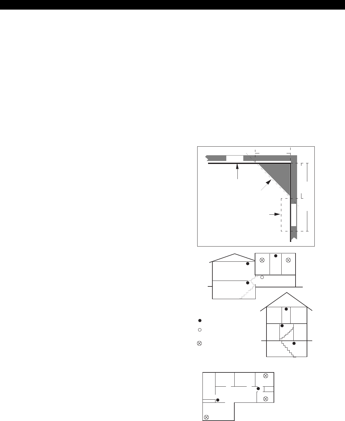
36
CEILING
SIDE WALL
Acceptable Here
Never Here
Top of Detector
Acceptable Here
4 in.(0.1m) Minimum
12 in.(0.3m) Maximum
NOTE: All measurements are to
the closest edge of the detector
4 in.(0.1m) Minimum
Consult smoke detector specifications and local and national
codes for coverage descriptions.
Bedroom BedroomHall
DiningLiving
Basement
A smoke detector should be located
on each story.
Basement
Living Bedroom BedroomHall
Recreation
Indicates required smoke detector
Indicates smoke detector is optional
if door is not provided between living
and recreational rooms.
Indicates smoke detector
required in new construction.
Bedroom
TV
Room
Dining Kitchen Bedroom
Bedroom
Living
In family living units with more than one sleeping
area, a smoke detector should be provided to
protect each sleeping area in addition to the
detectors required in bedrooms.
Testing
This system should be tested weekly. All switches,
contacts, and accessories must be UL Listed devices.
This equipment should be installed in accordance
with the National Fire Protection Association Stan-
dard No. 72 (National Fire Protection Association,
Batterymarch Park, Quincy MA 02269). Control
panel specifications are subject to change without
notice.
The National Fire and Burglar Alarm Association
(NFPA) has established rules to follow pertaining to
fire prevention and the installation of fire detection
equipment.
Smoke Detector Locations
For residential applications, install smoke detectors
in each bedroom and outside each separate sleep-
ing area in the immediate vicinity of the bedrooms
and on each additional story of the family living unit
including basement and excluding crawl spaces and
unfinished attics. In new construction, a smoke de-
tector should also be installed in each sleeping area.
For family living units with one or more split levels
(i.e.: adjacent levels with less than one full story sepa-
ration between levels), a smoke detector required
by the above is sufficient for an adjacent lower level,
including basements. EXCEPTION: Where there is
an intervening door between one level and the ad-
jacent lower level, install a smoke detection on the
lower level. For commercial applications, install
smoke detectors in each separate work area, includ-
ing hallways and storage areas.
Install ceiling-mounted smoke detectors in the cen-
ter of the room or hall, not less than 4 inches from
any wall. When mounting the detector on a wall,
place the top of the detector 4 to 12 inches from
the ceiling.
Do not install smoke detectors where normal ambi-
ent temperatures are above 100˚F. (37.8˚C.)
Do not position smoke detectors in front of air con-
ditioners, heating registers, ceiling fans, or other lo-
cations where normal air circulation will keep smoke
from entering the detector.
Heat from a fire rises to the ceiling, spreads out across
the ceiling surface and begins to bank down from
the ceiling. Corners where the ceiling and walls meet
create air spaces in to which heat has difficulty pen-
etrating. Usually, these dead air spaces measure
about four (4) inches (0.1m) along the ceiling from
the corner and four (4) inches (0.1m) down the wall.
Do not place heat or smoke detectors in these dead
air spaces.
NFPA RULES
National Fire Protection Association (NFPA) Rules
FIGURE 23 Smoke Detector Placement

37
SYSTEM TROUBLESHOOTING
AC FAILURE Indicates the loss of AC power or that the AC voltage is not high enough to power the system.
ALARM SILENCED Indicates that an Auxiliary or Holdup Alarm condition is present and the alarm has been manually silenced.
BELL 1 FAULT Indicates that there is a short or an open in the wiring or that the EOL is missing on Fire Bell 1 or that the Bell
Disconnect switch on the ZXCFM is on.
BELL 2 FAULT Indicates that there is a short or an open in the wiring or that the EOL is missing on Fire Bell 2 or that the Bell
Disconnect switch on the ZXCFM is on. ZX440F alternates monitoring between Fire Bell 1 and Fire Bell 2, so
it may take a minute before a fault or restore occurs.
BELL 1/BELL 2 SILENCED Indicates that a Fire Alarm condition is present and the Fire Bell(s) has been manually silenced. A manual
Smoke Reset is required to clear the alarm condition.
CALL RPM FAIL Indicates that an installer initiated call to the Remote Programming computer was unsuccessful.
COMM FAILURE Indicates that an event was not successfully communicated to the Central Station. This condition can be
cleared by disabling both phone lines.
FIRE TROUBLE Indicates that there is wiring problem on a Fire zone or that a Fire Alarm condition is present and the Fire
Bell(s) has been manually silenced. A manual Smoke Reset is required to clear the alarm condition.
GROUND FAULT Indicates an earth ground connection on any output circuit.
KEYPAD MISSING Indicates that a supervised keypad is no longer responding to polls from the control panel. Possible causes
include: The keypad has been removed or had its address changed, faulty data bus wiring, or multiple super-
vised keypads at the same address. This condition can be cleared by pressing the CLEAR key for 3 seconds.
LOW/NO BATTERY Indicates that the battery voltage is low or that no battery is present.
MEMORY ERROR Indicates that the system has detected corruption of Function Map data. This condition can only be cleared
by pressing the CLEAR key for 3 seconds.
NO COMMUNICATION Indicates that the keypad is not receiving commands from the control panel. Possible causes include: Faulty
data bus wiring, bad address setting on the keypad, control panel failure, or control panel shutdown due to
low operating voltage (hibernation mode).
NON-TELCO FAIL Indicates that Non-Telco event reporting has been selected, but the Non-Telco interface is not functioning.
PHONE LINE 1 FAIL Indicates that Phone Line Monitoring has been enabled for Phone Line 1 and a fault has been detected on
Phone Line 1. This condition can be cleared by disabling Monitoring of Phone Line 1.
PHONE LINE 2 FAIL Indicates that Phone Line Monitoring has been enabled for Phone Line 2 and a fault has been detected on
Phone Line 2. This condition can be cleared by disabling Monitoring of Phone Line 2. ZX440F alternates
monitoring between Phone Line 1 and Phone Line 2, so it may take several minutes before a fault or restore
occurs.
SMOKE TROUBLE Indicates that a Smoke Detector needs to be cleaned. This condition will clear automatically some time after
the detector(s) has been cleaned or it may be cleared by performing a Smoke Reset or by pressing the CLEAR
key for 3 seconds.
SUPERVISORY TROUBLE Indicates that there is a wiring problem on a Fire Supervisory zone or that a Supervisory Alarm condition is
present and has been manually silenced.
ZONE MISSING Indicates that the zone’s expansion device is not responding to polls from the control panel.
ZONE TROUBLE Indicates that a wiring problem exists on the zone or that a Burglar Tamper condition exists and the condition
has been silenced.
System Troubleshooting
When the system detects a trouble condition, it is
periodically displayed on the Control Station(s) and
a trouble tone is sounded. The trouble tone will
sound until it is either silenced (with an OFF +
passcode) or until the trouble condition restores. If
a trouble condition is silenced and then is still present
DESCRIPTIONTROUBLE
4 hours after it was silenced, then the trouble sounder
will be re-activated for 5 seconds and again every 4
hours. The display of a trouble condition will con-
tinue to appear until the condition either restores or
is cleared.
FROM CONTROL
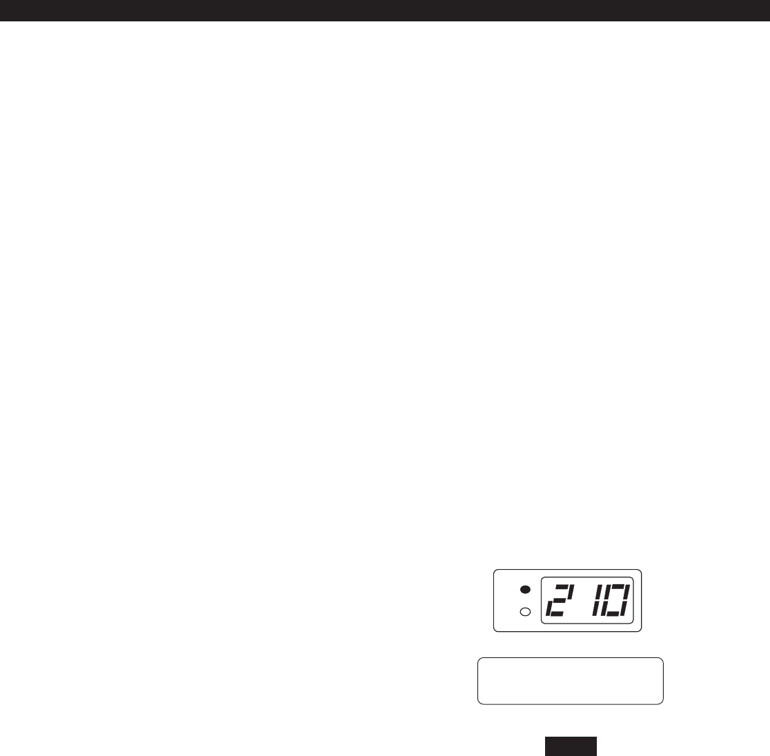
39
Powering Up With The Control
Station
The control comes from the manufacturer with a fac-
tory set (default) program. The factory default code
for user passcode No. 1 is 1234. This passcode is
authorized to perform all user level functions. The
default setting for the installer passcode is 9632. The
installer passcode can perform the installer level func-
tions. (See Installer Level Programming - User Data
Description for the listed functions). All zones and Con-
trol Stations are assigned to Area 1 at default. The de-
fault setting for user passcode No. 50 is 1245 and it
is authorized to perform all user level functions. It is
assigned to both Area 1 and 2.
When a Control Station is powered-up, it briefly dis-
plays a test pattern followed by its data bus address.
The Control Station will then begin displaying infor-
mation from the control panel. During the first fifteen
seconds after power-up, the control panel will instruct
the Control Station to display the panels software re-
vision and flash the AWAY, STAY, NIGHT, READY, and
TROUBLE LEDs.
Rev number may change as software
is upgraded.
Introduction
The Sentrol ZX440F Security System incorporates the
most desired operational features available today. The
ZX440F features ease of installation and programming
with an easy-to-operate keypad. Features such as cross-
zoning, and an audibles mute function on the key-
pad help reduce false alarms.
The ZX440F, when defaulted to Commercial Fire mode,
provides one 2-wire smoke detector zone and ten bur-
glar zones (one delay, two interior and seven instant).
Zones 6 & 12 are dedicated as Phone Line Monitor
and Ground Fault Monitor inputs and may not be used.
A Zone Expander Module (ZXEXP) may be added to
provide an additional 2-wire smoke detector zone and
up to 16 additional zones. Up to 16 RF Points may be
used with the 4710 and 4720 RF Gateways.
The ZX440F Security Control is easily programmed with
any one of four Control Stations (LCD, LED, SSD, or
VFD). The Controls on-board RAM maintains its data
even with the power disconnected.
The ZX440F Security Control allows the division of a
single system into two distinct areas, with an optional
common area. To the customer, each area appears to
be a fully functional system. The common area ap-
pears to be an extension of both areas. Each zone must
be assigned to one of the two areas or to the common
area. Each Control Station must be assigned to one of
the two areas and may be extended to operate in the
other area as a secondary area. The common area is
accessible to all Control Stations.
The Control may have up to 50 user codes. Each user
passcode must be assigned to one or both of the ar-
eas, and it must also be programmed with one of the
15 different levels of authority.
Operating the System
NOTE
OPERATING THE SYSTEM
PANEL REV 2.10
WITH FIRE MODULE
READY
TROUBLE
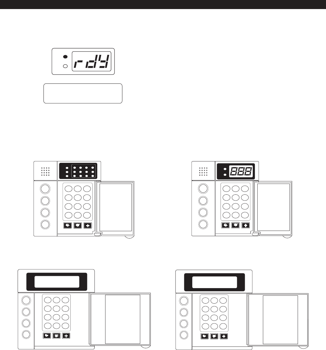
40
FIGURE 22 System Control Stations
OPERATING THE SYSTEM
Nearly every option on the control requires the use
of a valid user passcode. The user passcode may be
used for functions in a specific area or system-wide.
Most of the options may be performed at any time,
even while the control is fully or partially armed. To
perform a function, a user must press the key corre-
sponding to that function and then enter a passcode
with the appropriate authority level. For purposes
of discussion, the installer and the end user are both
considered system users, but have different levels of
authorization.
SSD Control Station
(ZXSSD)
LCD Control Station
(ZXLCD)
VFD Control Station
(ZXVFD)
LED Control Station
(ZXLED12)
AWAY
STAY
NIGHT
123
456
789
CLEAR
0
ENTER
VIEW INFO ALM MEM EVENT LOG
BYPASS DELAY ARM CHIME
RST SMOKE TEST PROGRAM
QUIT ACCESS INSTANT
HOME NEXT
D
OFF
CANCEL
AWAY
STAY
NIGHT
123
456
789
CLEAR
0
ENTER
VIEW INFO ALM MEM EVENT LOG
BYPASS DELAY ARM CHIME
RST SMOKE TEST PROGRAM
QUIT ACCESS INSTANT
HOME NEXT
D
OFF
CANCEL
C
AB
123
456
789
CLEAR
0
ENTER
NIGHT
STAY
AWAY
VIEW INFO ALM MEM EVENT LOG
BYPASS CHIME
RST SMOKE TEST PROGRAM
QUIT ACCESS INSTANT
HOME NEXT
PREV
READY
TROUBLE
FIRE
1234
56 78
11 12109
DELAY ARM
D
OFF
CANCEL
123
456
789
CLEAR
0
ENTER
NIGHT
STAY
AWAY
VIEW INFO ALM MEM EVENT LOG
BYPASS DELAY ARM CHIME
RST SMOKE TEST PROGRAM
QUIT ACCESS INSTANT
HOME NEXT
READY
TROUBLE
D
OFF
CANCEL
A1 READY TO ARM
JAN 21 05:27:52
READY
TROUBLE
Control Stations
Once the zones are in a secure state, the Control
Station displays:

41
Control Station Overview
For SSD, LED, LCD, and VFD Control Stations:
Away, Stay, and Night Keys These keys, followed by a passcode, arm one or both areas to the
AWAY, STAY, or NIGHT level.
Away, Stay, and Night LEDs These LEDs backlight the AWAY, STAY, and NIGHT keys to indicate the
armed level of the Control Stations primary area. These will flash
during Exit Time or during a Burglar Alarm after Dialer Delay has ex-
pired.
Off/Cancel Key This key, followed by a valid user code, disarms an area(s), silences
and cancels alarms, and silences trouble conditions.
Instant/Enter Key This key is used in programming to store entered data. Also, when
pressed during an exit time from a STAY or NIGHT arming, this key
disables both the entry and exit times for the primary area of the
Control Station.
Keypad Audibles The piezo resonator activates for conditions including entry and exit
notification, alarm, trouble, chime, etc.
Panic Keys When enabled, these keys activate the panic alarms (Fire, Police, Medi-
cal Emergency) or call a pager.
Clear/Quit Key This key is used to reset any entry error and to allow you to escape out
of an operation. To clear a Missing Keypad, Memory Error, or
Smoke Trouble system trouble condition or to turn off the Duress
output, press and hold the CLEAR key for three seconds.
Keyboard Backlighting The Control Station contains recessed LEDs to provide a light in dark
or dimly lit environments.
For SSD and LED Control Stations only:
Ready LED This LED indicates the status of the Burglar zones assigned to the Con-
trol Stations primary area. It illuminates when the Burglar zones are
all secure.
Trouble LED This LED will illuminate for system troubles (AC failure, low battery,
communication failure), zone troubles, and Burglar Tamper conditions.
(See Operating the System - Trouble Conditions for a complete list of
trouble conditions).
For LED Control Stations only:
Zone Status LEDs These LEDs generally indicate the condition of zones 1 through 12.
See the ZXLED8/ZXLED12 User Guide for how the LEDs indicate the
Normal, Faulted, Bypassed, Trouble, and Alarm conditions.
These LEDs may also display system trouble conditions and program-
ming information.
Fire Zone LED This LED indicates the status of the two-wire smoke zone on the main
control board (Zone 30).
For SSD Control Stations only:
Seven Segment Display The three Seven Segment Display (SSD) characters enunciate system
status, zone status and user information. See the ZXSSD User Guide for
details.
OPERATING THE SYSTEM

42
TEST KEY
This key allows you to perform one of the
six following tests: Walk, Battery, Bell,
Communications, Keypad, and RF Signal
Strength. After a valid passcode is en-
tered, you may select the test to perform.
PROGRAM KEY
This key is used to enter installer or user
level programming. User level program-
ming is described in the appropriate User
Guide. Installer level programming is
described in Installer Level Programming.
ACCESS KEY
This key is used to activate a door strike
or other similar function.
Secondary Function Keys
The Control Station secondary function keys may
be activated by pressing the ENTER key followed by
Key #1 through Key #6. A passcode is not required
to activate these functions. These functions are ac-
tivated by pressing the following:
+ Turns Lamp Trigger Output
ON or OFF
+ Turns Universal Output ON or
OFF
+ Quick Access from Keypad
+ Turns Key 4 Output ON or OFF
+ Turns Key 5 Output ON or OFF
+ Turns Key 6 Output ON or OFF
Please see Installer Level Programming - Output Defi-
nitions Description for more details on the operation
of these functions. The above outputs are only avail-
able to the user if you program them as Programmable
Outputs. If any of these features are made available to
the user, please instruct the user on their operation as
it is not detailed in the appropriate User Guide.
Control Station Function Keys
All Control Station function keys (except the View
Info Key) require that the function key be pressed
followed by a valid passcode. The passcodes au-
thority level will determine if the selected function
can be performed. While entering the passcode,
there will be a four second time-out for no activity.
After the passcode has been entered, there will be a
three minute time-out for no activity. The time-out
will return the Control Station to idle. The operator
may press the CLEAR key at any time to return the
Control Station to idle.
Below are the functions associated with keys 0 - 9
and a brief description of the functions. For details
on the operation of these functions, as well as on
the three arming keys, see the appropriate User
Guide.
VIEW INFO KEY
This key is used to view information and
scroll through alarm and trouble condi-
tions. A passcode is not required to per-
form this function.
ALM MEM KEY
This key allows you to view the most re-
cent alarm event(s) on the Control Sta-
tion.
EVENT LOG KEY
From an LED or SSD Control Station, this
key will initiate printing of the Event Log.
From an LCD or VFD Control Station, this
key will allow you to view the Event Log
on the Control Station or initiate print-
ing the log.
BYPASS KEY
This key allows you to select zones to be
bypassed (removed from the system) and
unbypassed (restored to the system).
DELAY ARM KEY
This key extends or postpones an auto-
matic arming by one hour.
CHIME KEY
This key turns the chime function on or
off for a particular area.
RST SMOKE KEY
This key resets all latched smoked detec-
tors and clears Smoke Troubles and
Bell Silenced.
OPERATING THE SYSTEM
1
2
3
4
5
6
0
7
8
9
ENTER
1
2
3
ENTER
ENTER
ENTER
4
ENTER
ENTER
5
6

43
Installer Arming and Disarming
The installer passcode may be used to arm one or
both areas. It may be used to disarm one or both
areas, but only if the area was armed by the installer
passcode. It may be used to silence alarms and to
silence trouble conditions. When it is used to si-
lence a Burglar alarm, it will not disarm the area or
cancel the alarm unless the area was armed by the
installer passcode. For a detailed description of arm-
ing and disarming procedures, see the appropriate
User Guide.
Installer On Premises
When the installer passcode is used to program Func-
tion Map data or User Codes, a Local Program Be-
gin event is logged to be reported. A Local Program
End event is logged to be reported 255 seconds after
the programming mode is exited or upon the CLEAR
key being pressed and held for three seconds.
Testing
The ZX440F provides the following testing capabili-
ties: Walk Test, Battery Test, Bell Test, Communicator
Test, Keypad Test and RF Signal Strength Test. Refer to
the appropriate User Guide for instructions on perform-
ing these tests. Always ensure that a Walk Test (and an
RF Signal Strength Test when applicable) is performed
on a new installation.
To test the Received Signal Strength of each RF Zone
Device, use Test 6 - RF Signal Strength Test. From
the Control Station press the 8 key, followed by
the Installer Code (9632) and then press the 6
key. Next press the RF Zone Device Number (13 to
28). The Control Station will display and sound the
Received Signal Strength of the last transmission sent
by the RF Zone Device. See results below:
Strong Signal (HOT or 5 Control Station beeps):
a strong or high level RF signal was measured by the
receiver for that location of the transmitter. This is a
good location for the transmitter and receiver.
Acceptable (ACC or 3 Control Station beeps): a
normal or acceptable level of RF signal was mea-
sured by the receiver for that location of the trans-
mitter. This is a good location for the transmitter
and receiver.
OPERATING THE SYSTEM
Low Signal (LOW or 1 Control Station beep): a low
or not acceptable level of RF signal was measured by
the receiver for that location of the transmitter. Make
multiple test transmissions, making sure that obstruc-
tions between the transmitter and receiver are normal
but minimized (hands away from units, metal ladders
away from receiver, etc.) during these tests. The trans-
mitter and/or receiver will need to be relocated to ob-
tain ACCEPTABLE level readings.
No Signal (NO or 1 long Control Station beep):
no RF signal or an extremely low RF signal was mea-
sured by the receiver for that location of the trans-
mitter. Bring the transmitter to the RF Gateway and
activate the transmitter. The red LED on the RF Gate-
way should blink. If it does not, then the transmitter
is not working. If the red LED does blink, but the
signal strength is still NO SIGNAL, then a program-
ming error exists. Check the programming of the
zone in both the RF Gateway and the panel. If the
signal strength is STRONG or ACCEPTABLE, then the
transmitter and/or receiver will need to be relocated
to obtain ACCEPTABLE level readings. Be sure to
power down the control to clear out all signal
strength levels before testing the transmitter at its
new location.
After testing has been completed, the RF Gateway and
RF Zone Devices should be permanently mounted.
Series 4000 RF Gateways and
transmitters which are not UL La-
beled are not allowed in UL Cer-
tificated installations.
NOTE

44
Area Partitioning
The control may be divided (partitioned) into two
independent areas. To the customer, each area ap-
pears to be a full-featured system. This allows one
control to be shared by two independent depart-
ments within a common structure.
LED Control Stations cannot have a
Secondary Area.
Each area can be programmed to control separate
outputs with a dedicated audible or annunciator. It
is also possible to combine the outputs of both ar-
eas so that a central siren, bell or audible can be
used. The audible should be positioned so that it
can be heard by all partitions. When partitioning is
not desired, simply designate all zones to a single
area (Area 1).
An example of a partitioning application is a busi-
ness that is divided into two departments with both
departments occupied by a different manager. The
control communicator would be installed in a se-
cure area (common utility closet) with dedicated and
uninterrupted AC power and telephone service. This
must be considered when planning the control panel
position as the power and phone service to a tenant
may be terminated if that tenant leaves.
Each tenants compartment is assigned an area with a
number of zones, codes, and Control Stations. When
an area experiences an alarm or other event, the adja-
cent system area is not alerted to the event since the
Control Station would be programmed to respond only
to events in the assigned area (see Table 1).
Another programming feature is the ability to allow
crossover between areas. This allows the user(s) from
one area to operate the other area from a desig-
nated Control Station. Programming is discussed in
detail later in this manual. By factory default, users
are only allowed to see and operate their primary
assigned area. Multi-area operation may be useful
for applications where the security system is installed
in a facility that is divided into departments. Each
department has a set of users who are responsible
Introduction
The control may be programmed locally from any
LED, SSD, LCD, or VFD Control Station. Throughout
this section, the three Panic keys are referred to as
the Left Panic key, Center Panic key and Right Panic
key.
Local Programming
There are two levels of Control Station programming:
User level and Installer level.
User Level Programming
Provides the ability to add, change, or delete user
passcodes. It also allows Scheduled Arming and
Latch Key operation to be changed. A user passcode
with authority level 9, 10, or 15 is required to access
the user level programming (see Installer Level Pro-
gramming - Authority Levels). See the appropriate
User Guide for more information regarding user level
programming.
Installer Level Programming
Allows total customization of the controls operat-
ing features. Only the installer code may access this
level. Anyone attempting installer level program-
ming should be familiar with the contents of this
publication prior to programming the control panel.
If the installer code is lost or forgot-
ten, it may be impossible to program
the control locally.
If remote programming is used, it is possible to lock-
out or prevent takeover of a control by another in-
stallation company by selecting Lockout Local
Prog. This prevents the installer passcode from
gaining access through local Control Station pro-
gramming. The installer passcode may still be used
for the non-programming functions described in
Installer Level Programming - Authority Levels. Lock-
out Local Prog does not affect remote program-
ming.
Programming the Control
PROGRAMMING THE CONTROL
NOTE
NOTE

45
for arming and disarming only the security system
to which they are assigned. If desired, the system
may be set up to allow one or more users to have
control over both areas (see Table 2).
Another programming feature is common area bur-
glar zones (see Operating the System - Introduction).
These zones may be used when a system needs to
be configured with two separate areas of protection
and a common area. For example, an office build-
ing with two separate offices and a common lobby.
The lobby (or common area) only gets armed when
both areas are armed in the AWAY mode. When one
area is armed in the AWAY mode, the common area
becomes an extension of the other area. When ei-
ther area is disarmed, the common area also is dis-
armed. Faulted common area zones may be viewed
on all Control Stations.
Arming and disarming operations with a common
area are the same as without a common area, ex-
cept that when an area is armed in the AWAY mode,
all common area zones may need to be secure.
Common area zones may not be force-armed, but
they may be bypassed. Common area zones may
be violated while either of the two areas is in Exit or
Entry time countdown.
Maximum Zones = 28
Up to 26 zones may be assigned to either area or
the common area (fire zones are system-wide and
have no area assignment).
Maximum Users = 50
Any number of users may be assigned to either or
both areas.
Maximum Supervised Control Stations = 6
SSD, LCD, and VFD Control Stations can be assigned
to operate in both areas if desired. LED Control Sta-
tions can only be assigned to operate in either Area
1 or Area 2.
PROGRAMMING THE CONTROL
When reporting to the Central Station, the control
has three sets of Account Numbers. One set for sys-
tem events, one set for Area 1 events and one set for
Area 2 events. Examples of System events include:
Fire Alarms and Troubles, Common Area Burglar
Alarms, AC Power Failure, Low Battery and automatic
tests. Examples of Area 1 or Area 2 events include:
Burglar Alarms, Holdup Alarms, Opening/Closings.
All events are grouped into several categories with
each category having options of reporting to receiver
A, receiver B and/or a Pager.
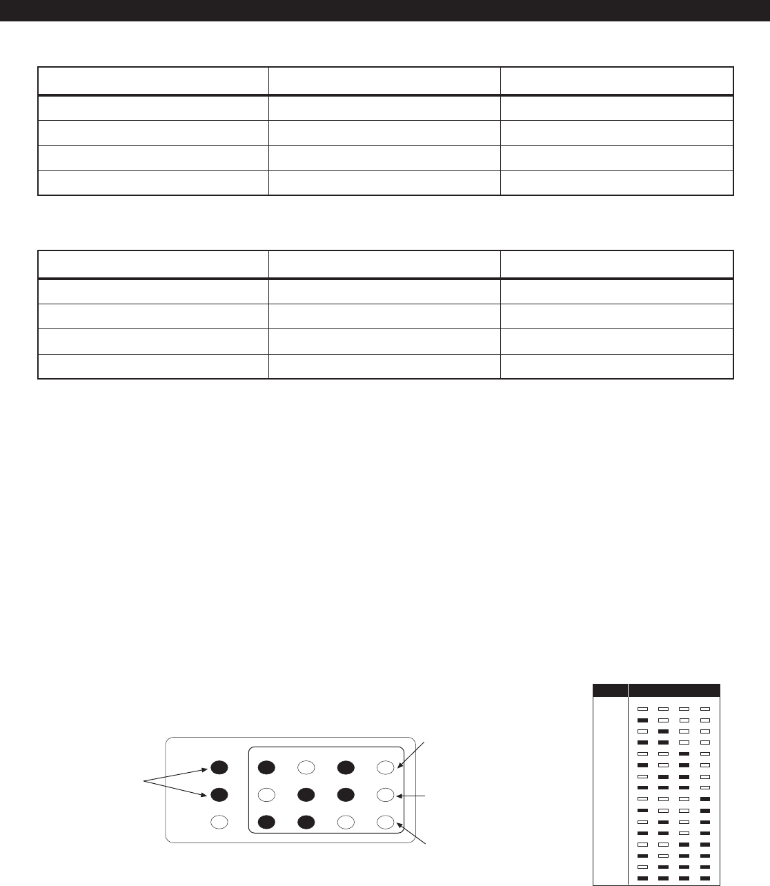
46
Figure 23 LED Display
LED Control Station Programming
When in programming mode, an LED Control Sta-
tion will mimic what is displayed on an SSD Control
Station. The top row of LEDs will correspond to the
first SSD character, the second row to the second
SSD character and the third row to the third SSD
character. If an SSD character is 1 - 9 or A - F, then
PROGRAMMING THE CONTROL
that hexadecimal digit will be displayed in binary
on the appropriate row of LEDs. See the Installer
Level Programming section for programming with
the Control Station. It will also show examples of SSD,
LCD, or VFD Control Station displays. There are no
examples for LED Control Stations (see Figure 23).
Value Display
0
1
2
3
4
5
6
7
8
9
10 (“A”)
11 (“B”)
12 (“C”)
13 (“D”)
14 (“E”)
15 (“F”)
1248
1
FIRE
READY
TROUBLE
234
5678
910
11 12
READY and
TROUBLE LEDs
Flash indicating that the
control is in programming
mode
ZONE LEDs (1 - 4)
Display hexadecimal value
corrresponding to left digit on SSD
Control Station (shown is '5')
ZONE LEDs (5 - 8)
Display hexadecimal value of
center digit (shown is '6')
ZONE LEDs (9 - 12)
Display hexadecimal value of
right digit (shown is '3')
SYSTEM AREA 1 AREA 2
System Account Numbers Area 1 Account Numbers Area 2 Account Numbers
Common Burglar Zones 7 & 8 Burglar Zones 1 - 3 Burglar Zones 4 - 5
Fire Zone 30 Users 1 - 3, 7 Users 4 - 7
Control Stations 1, 2, 5 Control Stations 3 - 5
Table 2 Two Areas with Two Common Burglar Zones (Zones 7 & 8)
A Multi-Area User Code (User 7) and a Multi-Area Control Station (Keypad 5)
Table 1 Two Separate Areas
SYSTEM AREA 1 AREA 2
System Account Numbers Area 1 Account Numbers Area 2 Account Numbers
Fire Zone 30 Burglar Zones 1 - 3 Burglar Zones 4 - 5
Users 1 - 3 Users 4 - 6
Control Stations 1 & 2 Control Stations 3 & 4
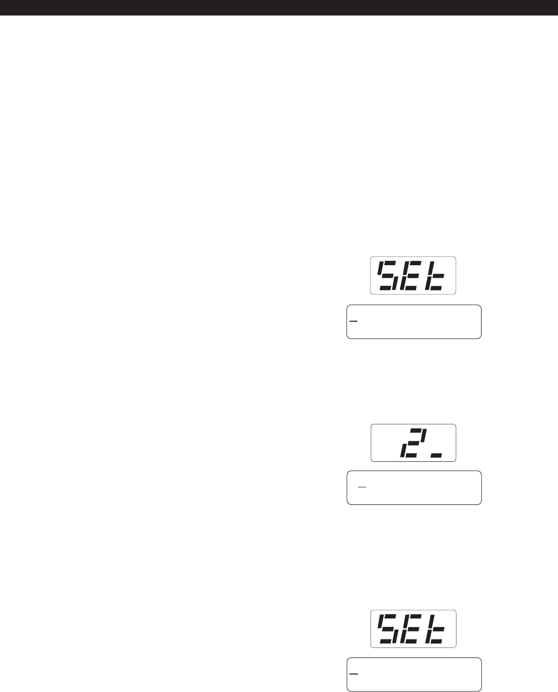
47
Set Clock
Press the 9 key and enter the installer passcode to
enter programming mode. Press the 2 key for Set
Clock programming. The Control Station will go into
clock set mode.
The SSD Control Station will have a Set Clock prompt
display. The LCD and VFD Control Station will dis-
play the current hour, minute, month, day, and year
(HH:MM MM/DD/YY). The zone LEDs on an LED
Control Station will remain off. The hour must be
entered in 24-hour format.
The operator may start entering numbers from the
first hour digit. As a number is entered, it is displayed
and the cursor automatically moves to the next po-
sition on the LCD and VFD Control Station. When a
digit is entered, the Control Station will display:
If the CLEAR key is pressed, the cursor will move
back to the first hour digit and any changes that
were entered will be erased, i.e.: the current time
and date will be re-displayed. If the CLEAR key is
pressed and no changes have been entered, the
Control Station will return to idle with no changes
to the time or date.
Menu Options
This section will describe Installer Level Programming
as performed locally from a Control Station.
To enter Installer Level Programming, press the PRO-
GRAM (9) key and enter the installer passcode (de-
fault = 9632). The Control Station will then prompt
you to select a programming option from 1 to 9
where:
1 = SET CLOCK
2 = EDIT FUNCTION MAP
3 = PROGRAMMING ZONE NAMES
4 = PROGRAMMING USER CODES
5 = RESTORE FACTORY DEFAULTS
6 = SET DAYS UNTIL NEXT COMM TEST
7 = PROGRAM RF DATA
Installer Level Programming
INSTALLER LEVEL PROGRAMMING
14:58 02/11/96
ENTER = COMPLETE
24:58 02/11/96
ENTER = COMPLETE
14:58 02/11/96
ENTER = COMPLETE
48
If the ENTER key is pressed, all changes that were
entered will be range checked. The entire time and
date need not be entered. Any fields that are not
entered will remain unchanged. If the data entered
is within range parameters, the clock will be updated
and the Control Station will return to idle. A Begin
Set Clock event will indicate the time before the
change and an End Set Clock event will indicate
the time after the change. If the entered data is out
of range, the Control Station will indicate an error,
erase the previous entries and re-display the current
time and date.
Edit Function Map
Press the 9 key and enter the installer passcode to
enter programming mode. Press the 3 key to en-
ter Edit Function Map mode. The Control Station
will prompt you for a location to be programmed.
The location numbers, definitions, and valid entries
for the locations are described in the Installer Level
Programming - Function Map section. From this
mode, you may edit the entire Function Map ex-
cept for User Codes and Zone Names. Editing Zone
Names is described in the Installer Level Program-
ming - Programming Zone Names section. Editing
User Codes is described in the Installer Level Pro-
gramming - Programming User Codes section.
From the LOCATION prompt, enter digits for the
desired location number. The digits entered will be
displayed. If more than three digits are entered, the
first digit entered will be discarded. If you make a
mistake, you may press the CLEAR key to clear out
the location and start over. When the desired loca-
tion number is displayed, press the ENTER key. The
Control Station will then display the current value
programmed at that location.
Entering a New Value at a Location
While the Control Station is displaying the value at a
location, you can enter digits to change the value at
that location. The new value is displayed as you
enter the digits. Other keys work as follows:
ENTER - if pressed after new digits are entered,
the displayed value is stored at the
current location.
- if pressed with no new digits entered,
then it will go to the next location.
Right Panic - if pressed, it will go back one loca-
tion and ignore any digits entered.
CLEAR - if pressed after new digits are entered,
the new digits will be erased and the
original value will be re-displayed at
the location.
- if pressed with no new digits entered,
then it will return to the LOCATION
prompt.
OFF CANCEL - on an LED or SSD Control Station, it
will momentarily display the present
location number.
When you press the ENTER key to
store the new value, the system will
store the value as entered. It is the
responsibility of the programmer to
enter a value within the specified
range. If the value entered is out of
the range, then undesirable operation
may occur. In some cases, if the value
entered is too large, it will be trun-
cated before it is stored causing a dif-
ferent value to be stored than was
entered.
INSTALLER LEVEL PROGRAMMING
INVALID SETTING
NOTE
Key

49
Programming Account Code and
Telephone Number Digits
When the location being programmed is an account
code or telephone number digit (see Installer Level
Programming - Communication Telephone Numbers
Description and Area Event Reporting Description),
the value will be displayed as an H followed by a
single digit. The H indicates that this location is a
Hexadecimal field. The valid entries for these loca-
tions are 0 through F, where A - F correspond
to 10 - 15 respectively.
To program a digit, enter digits as normal. To enter
an A - F, enter a 1 followed by a 0 through 5.
As in programming normal fields, if too many digits
are entered, the first digit entered will be discarded.
The ENTER, OFF CANCEL, Right Panic key, and CLEAR
keys will work the same as described above.
Programming Report Codes and Attribute
Fields
When the location being programmed is a report
code (see Installer Level Programming - Zone Re-
port Codes Description thru System Report Codes
Description) or an attribute field (see Installer Level
Programming - Area Data Descriptions thru Zone
Data Descriptions and System Report Codes Descrip-
tion thru Area Schedules Description), the value will
be displayed as an H followed by two digits. The
H indicates that this location is a Hexadecimal field.
The valid entries for these locations are 00 through
FF, where A - F correspond with 10 - 15 respec-
tively. The Control Station display will automatically
display the hexadecimal value.
To program one of these locations, enter digits as
normal. To display a 1 in the first digit location,
you must enter a 0 before the 1, i.e. 01 displays
a 1. To enter an A - F, enter a 1 followed by a 0
through 5. For example:
Enter To Get
1-2-3 C3
0-1-2 12
1-8 18
0-1-1-0 1A
1-2 0C
2-1 21
INSTALLER LEVEL PROGRAMMING
As in programming normal fields, if too many digits
are entered, the first digit entered will be discarded.
The ENTER, OFF CANCEL, Right Panic key, and CLEAR
keys will work the same as described above.
Additional Programming Notes
To exit out of Edit Function Map mode and return
the Control Station to the idle state, press the CLEAR
key from the LOCATION prompt. (You may need to
press the CLEAR key several times to get to the LO-
CATION prompt). An End Local Programming
event will not be logged until 255 seconds after you
exit programming mode. This is to allow you to exit
and re-enter programming mode repeatedly with-
out logging each one. To force an End Local Pro-
gramming event to be logged, immediately (i.e.:
to have it reported to the Central Station), press and
hold the CLEAR key for three seconds.
When programming the value at the last program-
ming location, the Control Station will return to the
LOCATION prompt if the ENTER key is pressed.
If the panel has been programmed from RPM/2 Pro
and the Agency Code has been loaded into the panel,
then the locations corresponding to the telephone
numbers and account codes will not be editable.
Programming Zone Names
Only the LCD and VFD Control Station may be used
to program zone names. Press the 9 key and enter
the installer passcode to enter programming mode.
Press the 4 key to program the zone names. The
Control Station will prompt you for a Zone ID to be
programmed. The valid Zone IDs are 1 - 5, 7 - 11,
13 - 30.
Enter a number corresponding to the Zone ID and
press ENTER. Once a valid Zone ID is selected, the
control will display the Zone ID and the current Zone
Name with the cursor on the first character. Press
the key associated with each character. Each keypress
will change the display to the next character listed
for that key. The characters available for program-
ming the Zone Names are located on the next page.

50
Programming User Codes
The installer passcode has the authority to program
user passcodes locally if Lockout Local Installer Pro-
gramming is disabled. The control may be pro-
grammed with up to 50 user passcodes. See Installer
Level Programming - User Data Description for in-
structions on setting the authority level and area as-
signment for each passcode. To program or change
a user passcode:
1. Press the 9 key and enter the installer passcode
to enter programming mode.
2. Press the 5 key to Program User Codes. The
Control Station will prompt you to enter the User
ID of the passcode that you wish to program.
3. Enter the ID number and press the ENTER key.
4. Enter the new four-digit passcode. The Control
Station will beep twice and return to the User ID
prompt.
5. Enter a new ID number or press the CLEAR key
to exit.
The entire passcode is displayed on an LCD/VFD
Control Station. Only one digit at a time is displayed
on an SSD Control Station. To view the existing
passcode on an SSD Control Station, press the EN-
TER key after each digit is displayed.
If the new passcode being entered is a duplicate of
an existing one, the Control Station will sound an
error tone and return to the first digit location so
that you may try again. To make a User passcode
inoperable, enter 0000 as the new four-digit
passcode.
INSTALLER LEVEL PROGRAMMING
Key #1 0 1 2 3 4 5 6 7 8 9 : ; < = > ? @
Key #2 A B C
Key #3 D E F
Key #4 G H I
Key #5 J K L
Key #6 M N O
Key #7 P Q R S
Key #8 T U V
Key #9 W X Y Z [ ¥ ] ^ _
Key #0 space ! # $ % & * + , - . /
Left Panic Key Used to move the cursor back one
position
Right Panic Key Used to move the cursor forward one
position
If the ENTER or CLEAR key is pressed and no changes
have been made, the Control Station will return to
the Zone ID prompt. If the CLEAR key is pressed
and changes have been made, all changes will be
cleared and the Control Station will return to dis-
playing the original Zone Name. To save any changes
made to the Zone Name, press the ENTER key. The
Control Station will return to the Zone ID prompt.
Press the CLEAR key to return to idle.
51
Restore Factory Defaults
This function provides a means to completely wipe
out the panels memory and restore it to a factory
default state. If successfully completed, the panel
will:
default the entire Function Map (including Zone
Names and User Passcodes)
clear the Event Log and log a System Startup
event
clear all alarm, trouble and armed conditions
not affect the System Clock (time and date)
Press the 9 key and enter the installer passcode to
enter programming mode. Press the 6 key to en-
ter Restore Factory Defaults mode. The Control Sta-
tion will prompt you to select the default mode.
For a ZX400 or ZX410, enter 0. For a ZX440F, enter
1. To convert a ZX410 to a ZX440F with a ZXCFK
(Commercial Fire Kit), you must default the panel
with option 1. Once the default mode is selected,
the Control Station will prompt you to re-enter the
installer passcode for verification.
The ZX440F will not function cor-
rectly if option 0 is enabled.
If it is entered correctly, the Control Station will go
back to the system powering up display.
TO DEFAULT PANEL
ENTER PASSCODE
Days Until Next Comm Test
The scheduling of Automatic Communications Tests
requires programming a Comm Test Time-of-Day
and the number of Days Between Comm Tests as
described in Installer Level Programming - Commu-
nicator Data Description. If Days Between Comm
Tests is zero, then no automatic comm tests will
occur. Otherwise, a comm test will occur when a
Days Until the Next Comm Test counter ticks down
to zero. This function allows you to view that Days
counter. If the value displayed is zero or one, then
the next comm test will occur at the next Comm
Test Time-of-Day. This function also allows you to
change the number of Days Until the Next Comm
Test.
Press the 9 key and enter the installer passcode to
enter programming mode. Press the 7 key to en-
ter Days Until Next Comm Test programming. The
Control Station will display the number of days until
the next scheduled comm test.
To change this value, enter a number between 0
and 255. If a mistake is made, press the CLEAR key
to start over. If a number greater than 255 is en-
tered, the first digit entered will be discarded. When
the desired number of days is displayed, press the
ENTER key. The Control Station will return to idle.
To exit out of this function without adjusting the
number of days, press the CLEAR key.
INSTALLER LEVEL PROGRAMMING
ENT 0=STANDARD
1=COMM FIRE
NOTE

52
Program RF Data
In order for an RF Zone Device or RF User Device to
be received by an RF Gateway, the address of the RF
Device must be programmed into the RF Gateway
(as described in the next two sections). The ZX440F
can support up to 12 RF User Devices per RF Gate-
way and up to 16 RF Zones. The 16 RF Zones are
programmed into the RF Gateways as devices 13-28
corresponding to zones 13-28. The 12 RF User De-
vices are programmed into a RF Gateway as devices
1-12 in any order (there is no correlation between
these devices and the Control Panels configuration
data). The 4710 RF Gateway is restricted to devices
13-20 for zones 13-20 and devices 1-12 for twelve
RF User Devices.
Programming RF Zone Devices Into the RF
Gateway
Press the 9 key and enter the installer passcode to
enter programming mode. Press the 9 key to Pro-
gram RF Data. The Control Station prompts you to
select an RF Gateway to program. Press 1 or 2.
The Control Station then prompts you to select an
RF Device to program.
Enter 13 thru 28 to select an RF Zone and press EN-
TER. The Control Station displays the eight digits
that are currently programmed in the RF Gateway
for that zone. For each digit, you may program a
new value by pressing a digit key. The Control Sta-
tion will automatically move to the next digit. To
move to the next digit without changing the cur-
rent digit, press the ENTER key.
The first digit to enter is the Supervision setting
where:
0 = Unsupervised
1 = Reserved
2 = Reserved
3 = 4 Hours
4 = 24 Hours
The next seven digits to enter come directly off of a
label on the RF Device.
If you make a mistake while entering the eight dig-
its, press the CLEAR key and the Control Station re-
turns to the first digit.
After the last digit is entered, the data is sent to the
RF Gateway and is confirmed and the Control Sta-
tion returns to the RF Device selection prompt. If
the data is successfully loaded into the RF Gateway,
the Control Station beeps twice. If the RF Gateway
does not respond, the Control Station sounds an
error tone and briefly displays an error message.
Check the data bus connections to the RF Gateway.
If the 8 digit number entered for the RF Zone is al-
ready stored in the RF Gateway for another zone,
the Control Station sounds an error tone and briefly
displays a message indicating the duplicate zone.
From the RF Device prompt, select another RF Zone
Device or press the CLEAR key to return to the RF
Gateway prompt. From the RF Gateway prompt you
can switch to program the other RF Gateway (if ap-
plicable) or press the CLEAR key to exit.
One RF Zone Device may be programmed into both
RF Gateways, but it must be programmed into a dif-
ferent zone on each gateway. When programming
RF Zone Data into two RF Gateways, be sure to note
which zones are programmed into each RF Gate-
way. When the zones are then programmed into
the Control Panel, select the correct RF Gateway as
the Expansion Device for that zone.
Programming RF User Devices Into the RF
Gateway
Press the 9 key and enter the installer passcode to
enter programming mode. Press the 9 key to Pro-
gram RF Data. The Control Station prompts you to
select an RF Gateway to program. Press 1 or 2.
The Control Station then prompts you to select an
RF Device to program.
Enter 1 thru 12 to select an RF User Device and press
ENTER. The Control Station displays the eight dig-
its that are currently programmed in the RF Gate-
way for that device. For each digit, you may pro-
gram a new value by pressing a digit key. The Con-
trol Station will automatically move to the next digit.
To move to the next digit without changing the cur-
rent digit, press the ENTER key.
The first digit to enter assigns the RF User Device to
a keypad. This is required to determine the area of
operation of the RF User Device and for the Access
function. Enter 1 thru 6 for a keypad assignment.
INSTALLER LEVEL PROGRAMMING

53
The second digit to enter defines the operation of
the key(s) on the RF User Device, where:
The next six digits to enter come directly off of a
label on the RF User Device.
If you make a mistake while entering the eight dig-
its, press the CLEAR key and the Control Station re-
turns to the first digit.
After the last digit is entered, the data is sent to the
RF Gateway and is confirmed and the Control Sta-
tion returns to the RF Device selection prompt. If
the data is successfully loaded into the RF Gateway,
the Control Station beeps twice. If the RF Gateway
does not respond, the Control Station sounds an
error tone and briefly displays an error message.
Check the data bus connections to the RF Gateway.
If the 8 digit number entered for the RF User Device is
already stored in the RF Gateway for another device,
the Control Station sounds an error tone and briefly
displays a message indicating the duplicate device.
From the RF Device prompt, select another RF User
Device or press the CLEAR key to return to the RF
Gateway prompt. From the RF Gateway prompt you
can switch to program the other RF Gateway (if ap-
plicable) or press the CLEAR key to exit. In most
cases, you can program an RF User device into both
RF Gateways.
INSTALLER LEVEL PROGRAMMING
Programming RF Devices Into the Control Panel
After the RF Devices have been programmed into
the RF Gateway, they must also be programmed in
the Control Panel. The programming options for the
Control Panels Function Map are described in In-
staller Level Programming - Function Map. When
RF Devices are used in an installation, be sure to con-
sider the following:
For an RF Zone Device, the zone data described in
Installer Level Programming - Zone Data Descrip-
tions must be programmed for the selected zone.
The Zone Type, Area Number and Burglar Zone At-
tributes locations are programmed as usual. The
Expansion Device location must be set to the ap-
propriate RF Gateway for the zone. The first digit of
Zone Attributes location doesnt need to be pro-
grammed because it is ignored for Wireless Zones,
but the second digit must be programmed as usual.
For an RF User Device, a user passcode must be cre-
ated that consists of the last four digits of the RF
Devices address (see Installer Level Programming -
Programming User Codes). An appropriate author-
ity level and area assignment must also be pro-
grammed for that user (see Installer Level Program-
ming - User Data Description). It is also required that
either the area assignment of the user passcode or
the area assignment of the associated keypad must
be a single area (i.e. an RF User Device on an RF
Gateway can only operate on one area). An RF User
Device can be programmed into two RF Gateways
with different keypad assignments on each. If the
devices passcode is operational in both areas and
the keypad on one RF Gateway is operational in one
area and the keypad on the other RF Gateway is
operational on the other area, then the RF User De-
vice can operate on either area depending on which
RF Gateway detects it.
NOTENOTE
For UL 1637 Home Health Care, RF
User Devices may only be assigned
to user passcodes 1-30.
SEC KEY KEY KEY KEY
DIGIT A B C D
1 AWAY STAY NIGHT OFF/CANCEL
2 AWAY STAY ACCESS OFF/CANCEL
3 AWAY STAY PANIC/HOLDUP OFF/CANCEL
4 AWAY STAY AUX/MED OFF/CANCEL
5 AWAY STAY ENTER 4 OFF/CANCEL
6 AWAY PANIC/HOLDUP ENTER 4 OFF/CANCEL
7 STAY PANIC/HOLDUP ENTER 4 OFF/CANCEL
8 STAY PANIC/HOLDUP AUX/MED OFF/CANCEL
9 AWAY ENTER 4 ENTER 6 OFF/CANCEL

54
AWAY Exit Delay Time 0 to 255 seconds
STAY & NIGHT Exit Time 0 to 255 seconds
Entry Delay Time 1 0 to 255 seconds
Entry Delay Time 2 0 to 255 seconds
Pre-Alarm Warning Time 0 to 255 seconds
Panic Key Alarms 00 to 33
(see the Panic Key Table)
Closing Ringback 0 = Ringback Output
1 = Ringback Output and
Keypads
2 = Ringback Output, Bell
Output and Keypads
Burglar Audible Lockout 0 = No Lockout
1 to 15 = Alarms for an Area
Time in seconds for all Burglar zones, may be audibly annunci-
ated. (See Inst. Level Prog. - Prog. Notes, Note 1).
Time in seconds for all Burglar zones, always silent.
Time in seconds to enter Burglar zones defined as Delay #1, may
be audibly annunciated. (See Inst. Level Prog. - Prog. Notes,
Note 1A).
Time in seconds to enter Burglar zones defined as Delay #2, may
be audibly annunciated.
Time in seconds to correct a false alarm, always audible.
(See Inst. Level Prog. - Prog. Notes, Note 2).
The first digit defines the annunciation of an alarm activated by
the Center Panic key. The second digit defines the annunciation
of an alarm activated by the Right Panic key. Either key may also
be used to initiate a call to a pager.
Determines how the system annunciates the successful trans-
mission of an AWAY closing report to the Central Station.
Determines the number of times that a Bell Output may be acti-
vated during an armed cycle, resets with disarm.
When entering values into the pro-
gramming locations, it is possible to
enter values which exceed the valid
range of the programmed options. It
is the responsibility of the installer to
ensure the correct value of any entry
programmed into the control. The
valid entries for each location are de-
tailed in the following sections.
Area Data Descriptions
The following table refers to programming locations
1 through 20.
Function Map
To edit the Function Map, press the PROGRAM (9)
key, enter the installer passcode, and press the 3
key to select the Edit Function Map programming
option. The Control Station will prompt for a loca-
tion to be programmed. All function map locations
can be programmed except for user codes and zone
names.
INSTALLER LEVEL PROGRAMMING
NOTE
ITEM VALID RANGE DESCRIPTION

55
Swinger Shunt 0 = No Shunt
1 to 15 = Violations for a Zone
Area Attributes 00 to FF
(see the Area Attribute Table)
Determines the number of violations that may occur from an
armed burglar zone before that zone is automatically bypassed.
Bypassing - enables selective bypassing of any zone that is de-
fined as bypassable in this area.
Force-Arming - permits arming of the area with zones faulted.
Faulted zones are temporarily bypassed and return to opera-
tion if the fault is corrected. Only zones that are defined as
bypassable may be force-armed. (See Inst. Level Prog. - Prog.
Notes, Note 4).
Exit Arm - (See Inst. Level Prog. - Prog. Notes, Note 3).
3 Second Panic Keys - requires all panic keys to be pressed and
held for approximately 3 seconds in order to activate alarm
condition. Only pertains to Control Stations that are Primary
to this area.
Double Press Panic Keys - requires all panic keys to be pressed
twice within one second to activate. Only pertains to Control
Stations that are Primary to this area.
Two Button Arm - enables quick arming by pressing AWAY,
STAY, or NIGHT followed by the ENTER key. Cannot be used
with force-arming.
Double Press Arm - enables quick arming by pressing AWAY,
STAY, or NIGHT twice. Cannot be used with force-arming.
Open After Alarm - enables opening reports to be reported
only if they occur after an alarm. All opening events will be
logged in the Event Log regardless of setting.
Display Bypass Armed - when armed in STAY or NIGHT mode
with bypassed or force-armed zones, Control Stations with the
area as the Primary area will indicate that there are zones that
are bypassed.
ITEM VALID RANGE DESCRIPTION
INSTALLER LEVEL PROGRAMMING
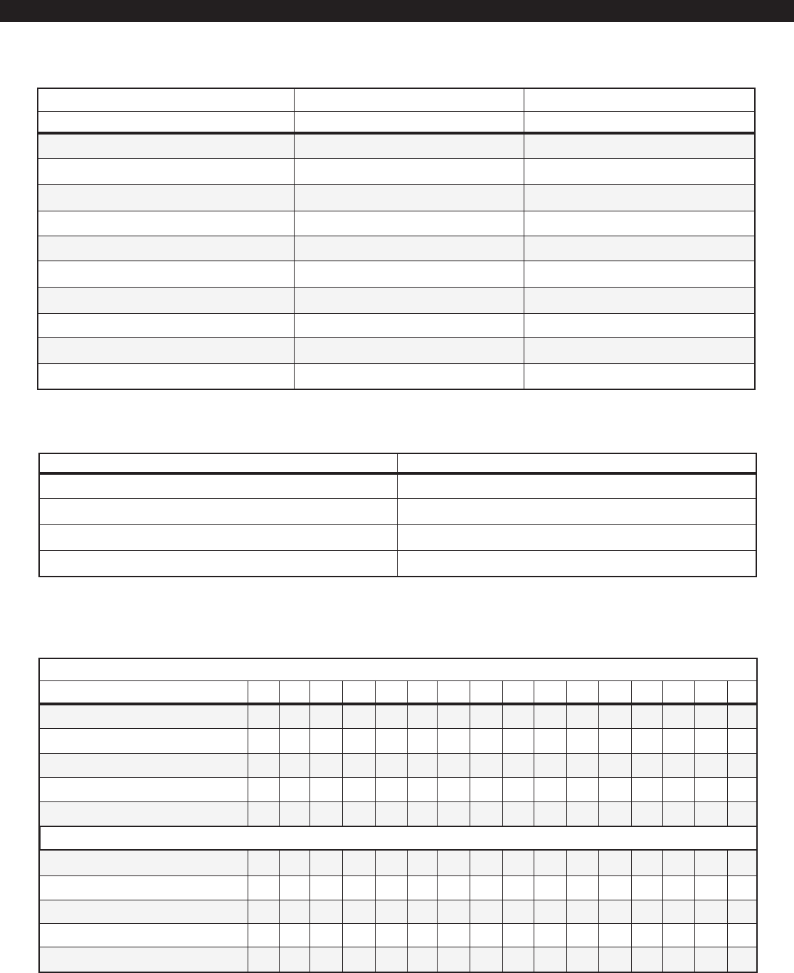
56
Area Data Default Table
INSTALLER LEVEL PROGRAMMING
0123456789ABCDE F
All Features Below Disabled
Two Button Arm
Double Press Arm
Open After Alarm
Display Bypassed Armed
Double Press Panic Keys
Bypass
Force-Arm
Exit Arm
3 Second Panic Keys
•
FIRST DIGIT
Area Attribute Table
ENTER FOR:
••••• •••
•• •••• ••
•••• ••••
••••••••
SECOND DIGIT
••••••••
••••••••
•• •• •• ••
••••••
•• ••
••••••
If the First Digit entered is 1, it must be entered as 01. A = 10; B = 11; C = 12; D = 13; E = 14; F = 15
AREA 1 AREA 2
Loc Default Loc Default
AWAY Exit Time (sec) [1] 60 [11] 60
STAY/NIGHT Exit Time (sec) [2] 60 [12] 60
Entry Time 1 (sec) [3] 20 [13] 20
Entry Time 2 (sec) [4] 40 [14] 40
Pre-Alarm Time (sec) [5] 0 [15] 0
Panic Key Alarms [6] H-21 [16] H-21
Closing Ringback [7] 0 [17] 0
Burglar Audible Lockout [8] 0 [18] 0
Swinger Shunt [9] 0 [19] 0
Area Attributes [10] H-09 [20] H-09
FIRST DIGIT (Center Panic Key) SECOND DIGIT (Right Panic Key)
0 = No Keypad Sounder or Bell Output (invisible) 0 = No Keypad Sounder or Bell Output (visible)
1 = Keypad Sounder Only 1 = Keypad Sounder Only
2 = Keypad Sounder and Bell Output 2 = Keypad Sounder and Bell Output
3 = Call Pager, No Alarm 3 = Call Pager, No Alarm
If the First Digit entered is 1, it must be entered as 01
Panic Key Table

57
INSTALLER LEVEL PROGRAMMING
Keypad Data Default Table
The following table refers to programming locations
21 through 32.
Keypad Attributes 00 to FF
(see the Keypad Attribute table.)
Access Time 0 = Toggle
1 - 255 seconds
ITEM VALID RANGE DESCRIPTION
This control is not a UL Listed Access Control System. The access feature should not be used in UL
Listed installations.
Keypad Data Descriptions
KEYPAD 1 KEYPAD 2 KEYPAD 3 KEYPAD 4 KEYPAD 5 KEYPAD 6
Loc Default Loc Default Loc Default Loc Default Loc Default Loc Default
Keypad Type LED LED SSD SSD LCD/VFD LCD/VFD
Keypad Attribute [21] H-1C [23] H-1C [25] H-1C [27] H-1C [29] H-1C [31] H-1E
Access Time (sec) [22] 5 [24] 5 [26] 5 [28] 5 [30] 5 [32] 5
Primary Area 1 or 2 - determines which area the Control
Stations status indicator will reflect and which area the Con-
trol Station will display area status for when it is idle.
Secondary Area Enabled - (See Inst. Level Prog. - Prog. Notes,
Note 5).
Left Panic Key Enabled - defines if the Left Panic key is to be
enabled for Fire at this Control Station.
Center Panic Key Enabled - defines if the Center Panic key is to
be enabled for Police or pager at this Control Station.
Right Panic Key Enabled - defines if the Right Panic key is to be
enabled for Medical/Emergency or Pager at this Control Station.
Silent Exit Time - silences the exit alert at the Control Station.
Silent Entry Time - silences the entry alert at the Control Sta-
tion. This does not affect Pre-Alarm Warning Time.
Silent Trouble - silences the trouble conditions at the Control
Station.
Time in seconds for an access output activated from this Con-
trol Station. Toggle access feature allows the output to latch
ON/OFF.
All access outputs assigned to this Control Station are affected
when the access function and a valid code is entered for this
Control Station (See Inst. Level Prog. - Output Definitions De-
scription). It is not area dependent. Typically used to activate
electrically operated door strikes.
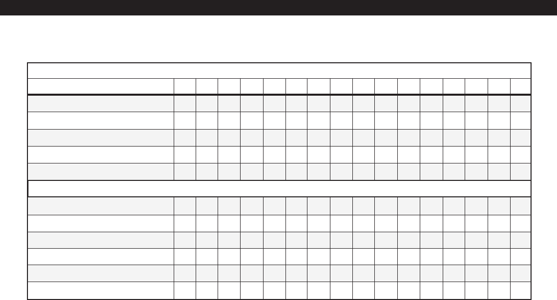
58
INSTALLER LEVEL PROGRAMMING
Keypad Attribute Table
0123456789ABCDE F
All Features Below Disabled
Right Panic Key Enabled
Silent Exit Time
Silent Entry Time
Silent Troubles
Primary Area 1
Primary Area 2
Primary Area 1, Secondary Area 2
Primary Area 2, Secondary Area 1
Left Panic Key Enabled
Center Panic Key Enabled
•
FIRST DIGIT
ENTER FOR:
••••• •••
•• •• •• ••
•••• ••••
••••••••
SECOND DIGIT
••
•••
••
••••
•••
•••••••••
If the First Digit entered is 1, it must be entered as 01. A = 10; B = 11; C = 12; D = 13; E = 14; F = 15
•
••
••••
•
•

59
ZONE EXPANSION BURGLAR ZONE ZONE
TYPE DEVICE ATTRIBUTE ATTRIBUTE
Loc Default Loc Default Loc Default Loc Default Loc Default
Zone 01 [33] 1 [34] 1 [35] H-0D [36] H-37
Zone 02 [37] 1 [38] 1 [39] H-03 [40] H-37
Zone 03 [41] 1 [42] 1 [43] H-03 [44] H-37
Zone 04 [45] 1 [46] 1 [47] H-0C [48] H-37
Zone 05 [49] 1 [50] 1 [51] H-0C [52] H-37
Zone 06 [53] 0✝[54] 0✝[55] H-0C N/A [56] H-37 N/A
Zone 07 [57] 1 [58] 1 [59] H-0C [60] H-37
Zone 08 [61] 1 [62] 1 [63] H-0C [64] H-37
Zone 09 [65] 1 [66] 1 [67] H-0C [68] H-37
Zone 10 [69] 1 [70] 1 [71] H-0C [72] H-37
Zone 11 [73] 1 [74] 1 [75] H-0C [76] H-37
Zone 12 [77] 0✝[78] 0✝[79] H-0C N/A [80] H-37 N/A
Zone 13 [81] 1 [82] 0 [83] 0 [84] H-0C [85] H-37
Zone 14 [86] 1 [87] 0 [88] 0 [89] H-0C [90] H-37
Zone 15 [91] 1 [92] 0 [93] 0 [94] H-0C [95] H-37
Zone 16 [96] 1 [97] 0 [98] 0 [99] H-0C [100] H-37
Zone 17 [101] 1 [102] 0 [103] 0 [104] H-0C [105] H-37
Zone 18 [106] 1 [107] 0 [108] 0 [109] H-0C [110] H-37
Zone 19 [111] 1 [112] 0 [113] 0 [114] H-0C [115] H-37
Zone 20 [116] 1 [117] 0 [118] 0 [119] H-0C [120] H-37
Zone 21 [121] 1 [122] 0 [123] 0 [124] H-0C [125] H-37
Zone 22 [126] 1 [127] 0 [128] 0 [129] H-0C [130] H-37
Zone 23 [131] 1 [132] 0 [133] 0 [134] H-0C [135] H-37
Zone 24 [136] 1 [137] 0 [138] 0 [139] H-0C [140] H-37
Zone 25 [141] 1 [142] 0 [143] 0 [144] H-0C [145] H-37
Zone 26 [146] 1 [147] 0 [148] 0 [149] H-0C [150] H-37
Zone 27 [151] 1 [152] 0 [153] 0 [154] H-0C [155] H-37
Zone 28 [156] 1 [157] 0 [158] 0 [159] H-0C [160] H-37
Zone 29* [161] 0 [162] H-63
Zone 30** [163] 2 [164] H-63
INSTALLER LEVEL PROGRAMMING
Zone Data Descriptions
Zone Data Default Table
AREA
* Zone 29 is the Two-Wire Smoke Zone on the ZXEXP Module
** Zone 30 is the Two-Wire Smoke Zone on the Control Board
ZX440F uses Zone 6 and Zone 12 for Telco Monitor and Ground Fault Monitor inputs.
They are not available for programming.
✝

60
The following table refers to programming locations
33 - 164.
INSTALLER LEVEL PROGRAMMING
Zone Type 0 = Not Used
1 = Burglar
2 = 24 Hour Fire
3 = 24 Hour Holdup
4 = 24 Hour Auxiliary
5 = Momentary Keyswitch
(Arm AWAY/Disarm)
6 = 24 Hour Communicator
7 = 24 Hour Burglar Tamper
8 = Universal
9 = Universal Logged
10 = Verified Fire
11 = Fire Supervisory
12 = Reserved
13 = 24 Hour Water Flow
14 = 24 Hour Non-Alarm
Area Number 0 = Disable
1 = Area 1
2 = Area 2
3 = Common Area
Expansion Device 0 = ZXEXP
1 = RF Gateway 1
2 = RF Gateway 2
3 = ZEM
Burglar Zone Attributes 00 to FF
(see the Burglar Zone
Attribute Table)
Zone Attributes 00 to FF
(see the Zone Attribute Table)
ITEM VALID RANGE DESCRIPTION
Note: Zone 29 & 30 may
only be programmed as
24 Hour Fire, Verified
Fire, Fire Supervisory, 24
Hour Water Flow or Not
Used; any other will be
interpreted as Not Used.
All other zones may be
programmed as any
zone type.
Critical Condition Monitor (CCM), no local display.
May be used to activate an output that is programmed as Uni-
versal. Only the Universal Logged is posted in the Event Log
when activated. No events are reported to the Central Station.
Upon activation, control resets switched smoke power. The
loop is ignored for 30 seconds. Subsequent activation within
the next 60 seconds causes an alarm.
See Inst. Level Prog. - Prog. Notes, Note 16.
Communicator with local display, but no local sounder.
Determines which area the zone belongs to. Fire zones are
visible to both areas regardless of settings. Only Burglar zones
may be assigned to the Common Area (see Operating the
System - Introduction).
Determines which data bus device the system will poll to get
the zones status data.
See Inst. Level Prog. - Prog. Notes, Note 2, 6, and 7 for a
complete description of the Burglar Zone Attributes. The
Chime Always attribute may be used with Universal zones as
well as Burglar zones.
Bell Output on Alarm - determines if Bell Output activates
due to an alarm from the zone. (See Inst. Level Prog. - Prog.
Notes, Note 8).
Keypad Sounder on Alarm - determines if Control Station
sounder activates due to an alarm from the zone. (See Inst.
Level Prog. - Prog. Notes, Note 8).
Fire Bell 2 on Alarm - determines if Fire Bell 2 activates due to an
alarm from the zone. This only applies to Fire and Verified Fire
Zones on where there is no Water Flow Zone. (See Inst. Level
Prog. - Prog. Notes, Note 8).
Bypassable - determines if a zone may be bypassed or force-
armed. (See Inst. Level Prog. - Prog. Notes, Note 17).
Secure Watch - (See Inst. Level Prog. - Prog. Notes, Note 9).
Zone Supervision - determines how opens and shorts are
handled.
Fast Zones - only applies to zones 1 - 12. A Fast Zone on
zones 1 - 6 has a loop response time of 80 msec. A Fast Zone
on zones 7 - 12 has a loop response time of 20 msec.
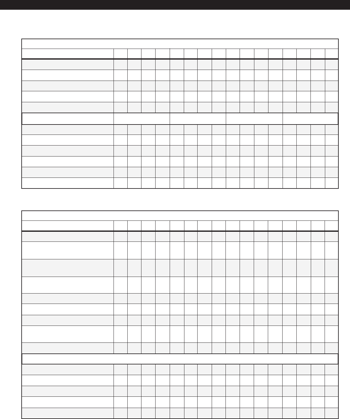
61
•
0123456789ABCDE F
Invalid
Alarm on Open - No Trouble
(EOL optional)
Alarm on Short - No Trouble
(EOL optional)
Alarm on Open or Short - No Trouble
(with EOL)
Trouble on Open or Short
Alarm on Open - Trouble on Short
Alarm on Short - Trouble on Open
Alarm on Open or Short - Trouble
on Open when disarmed (Burg only)
Fast Zones
All Features Below Disabled
Bell Output on Alarm
Keypad Sounder/Fire Bell 2 on Alarm*
Bypassable
Secure Watch
INSTALLER LEVEL PROGRAMMING
•
FIRST DIGIT
Burglar Zone Attribute Table
ENTER FOR:
••••••••
•• •• •• ••
•••• ••••
••••••••
SECOND DIGIT
•• ••
••••
••••
•••
••
•••
••
••
Armed AWAY only
(interior) Armed AWAY &
STAY Armed AWAY &
NIGHT
Armed AWAY, STAY &
NIGHT (perimeter)
•
•
••••
•
FIRST DIGIT
Zone Attribute Table
ENTER FOR:
•
•
•
•
•
•
•
•
•
•
•
SECOND DIGIT
•
••
••
•
•
•
•
•
•
•
•••
••••
•• •
•
•• •
•
•
•••••
•
•
••••••••
If the First Digit entered is 1, it must be entered as 01. A = 10; B = 11; C = 12; D = 13; E = 14; F = 15
The first digit of the zone attribute is ignored for RF and ZEM zones.
The only valid zone attributes for Zones 29 and 30 are 61, 62, 63, 65, 66 and 67.
* Keypad Sounder for Non-fire zones, Fire Bell 2 for fire zones.
0123456789ABCDE F
Standard (all below disabled)
Chime Always
Verifying
Self-Verifying
Sentry Test
Instant
Delay 1
Delay 2
Follower
Arm STAY
Arm NIGHT
••

62
AUTHORITY OPERATION AUTHORITY OPERATION
LEVEL AREA LEVEL AREA
Default Loc Default Loc Default Default Loc Default Loc Default
User 01 1234 [165] 10 [166] 1 User 26 0000 [215] 6 [216] 1
User 02 0000 [167] 6 [168] 1 User 27 0000 [217] 6 [218] 1
User 03 0000 [169] 6 [170] 1 User 28 0000 [219] 6 [220] 1
User 04 0000 [171] 6 [172] 1 User 29 0000 [221] 6 [222] 1
User 05 0000 [173] 6 [174] 1 User 30 0000 [223] 6 [224] 1
User 06 0000 [175] 6 [176] 1 User 31 0000 [225] 6 [226] 1
User 07 0000 [177] 6 [178] 1 User 32 0000 [227] 6 [228] 1
User 08 0000 [179] 6 [180] 1 User 33 0000 [229] 6 [230] 1
User 09 0000 [181] 6 [182] 1 User 34 0000 [231] 6 [232] 1
User 10 0000 [183] 6 [184] 1 User 35 0000 [233] 6 [234] 1
User 11 0000 [185] 6 [186] 1 User 36 0000 [235] 6 [236] 1
User 12 0000 [187] 6 [188] 1 User 37 0000 [237] 6 [238] 1
User 13 0000 [189] 6 [190] 1 User 38 0000 [239] 6 [240] 1
User 14 0000 [191] 6 [192] 1 User 39 0000 [241] 6 [242] 1
User 15 0000 [193] 6 [194] 1 User 40 0000 [243] 6 [244] 1
User 16 0000 [195] 6 [196] 1 User 41 0000 [245] 6 [246] 1
User 17 0000 [197] 6 [198] 1 User 42 0000 [247] 6 [248] 1
User 18 0000 [199] 6 [200] 1 User 43 0000 [249] 6 [250] 1
User 19 0000 [201] 6 [202] 1 User 44 0000 [251] 6 [252] 1
User 20 0000 [203] 6 [204] 1 User 45 0000 [253] 6 [254] 1
User 21 0000 [205] 6 [206] 1 User 46 0000 [255] 6 [256] 1
User 22 0000 [207] 6 [208] 1 User 47 0000 [257] 6 [258] 1
User 23 0000 [209] 6 [210] 1 User 48 0000 [259] 6 [260] 1
User 24 0000 [211] 6 [212] 1 User 49 0000 [261] 6 [262] 1
User 25 0000 [213] 6 [214] 1 User 50 1245 [263] 10 [264] 3
User Data Default Table
User Data Description
The user data block is used to set the level of au-
thority that determines the level of activity the user
can perform on the control and the areas that a par-
ticular user can perform operations on. The
passcodes associated with each user may be pro-
grammed as described in Installer Level Program-
ming - Programming User Codes.
INSTALLER LEVEL PROGRAMMING
CODE CODE

63
Authority Levels
Authorities levels 1 through 10 are the general pur-
pose levels with level 10 having the highest capa-
bilities. Level 11 is for limited disarm capabilities
(ie: Maids passcode). Level 12 is for User on Pre-
mises reporting. Level 13 is for Duress reporting.
For High Level Security applications, only levels 14
and 15 should be used. If levels 14 and 15 are used,
all other users should be set to Level 0 (zero).
Level 14 needs 2 different level 14 passcodes in
order to activate any of the options available. The
Control Station will beep 4 times after the 1st
passcode is entered signifying that it has been ac-
cepted. The 2nd passcode may then be entered.
Level 15 is for maintenance activities only. Level 15
does not allow the user to arm or disarm the sys-
tem, only to maintain it.
See the table on the next page for the options avail-
able for each authority level. To disable all capabili-
ties, set the authority level to zero (0).
INSTALLER LEVEL PROGRAMMING
ITEM VALID RANGE DESCRIPTION
The following table refers to programming locations
165 - 264.
Authority Level 0 to 15
Areas of Operation 0 = Disabled
1 = Area 1
2 = Area 2
3 = Both
See table on following page for Authority Level options.
(Enter 0 to disable).
Determines which areas the passcode can be used to perform
operations on. If a 3 is selected, the Control Station it is used on
must be programmed for both areas in order to access both
areas.
The Installer passcode has the authority level to perform the following operations:
Access from Keypad * Initiate Call to RPM/2 Pro
Arm (AWAY, STAY, NIGHT) * Remote Connect
Disarm if Armed by an Installer * Reset Smoke Power
Change Arming Level * Program RF Data
Edit User Codes * RF Signal Strength
Edit Zone Names * Set Clock
Force-Arm * Silence Trouble
View & Print Event Log * View Alarm Memory
Bypass Zones * Battery Test
Chime Enable/Disable * Bell Test
Default Function Map * Comm Test
Edit Function Map (except Zone Names & User Codes) * Keypad Test
Silence/Cancel Alarm if not Armed or if Armed by Installer * Walk Test
Silence Bell without Disarm if Armed by other than Installer Adjust Days Until Next Auto Comm Test
∗ Disabled if Lockout Local Programming is enabled (see Installer Level Programming - Programming Options).

64
INSTALLER LEVEL PROGRAMMING
•
CAPABILITIES
AUTHORITY LEVEL
•
•••• •
•••
•••••
••••••
••
••
••
•• •
••• ••
•
•• •
•
•••
••
•
•••••
••••••••••
•••••
•••••
••
••
•••
••
••••••••• ••••
••••
•••
•• •• ••
•••••
••
••
•• ••
•••••
•••• ••
••••••
••••••
•••• ••
•••• ••
••• ••
••• ••
•• ••
••
••
•• ••
••
•••• ••
•
•••
•
•
•
•
•
•
•
•
•
•
•
✝
✝
For High Level Security applications only
✝The Off/Cancel key followed by a Duress or User On Premises passcode will always produce a Duress or User On Premises report regardless
of whether the system was armed.
Edit User Codes
Disarm If Armed By A Level 11
User Passcode
Silence/Cancel Alarm If Not Armed
Or If Armed By A Level 11 Passcode
Silence Bell Without Disarm If Armed
By Other Than A Level 11 Passcode
Access From Keypad With User On
Premises Report
Silence/CancelAlarm With User On
Premises Report
Disarm With User On Premises Report
Access From Keypad With Duress
Arm (AWAY, STAY, NIGHT) with Duress
Change Arming Level With Duress
Force-Arm With Duress
Silence/Cancel Alarm With Duress
Disarm With Duress
••
123456789101112131415
Access From Keypad
Chime Enable/Disable
Silence Bell Without Disarm
Arm (AWAY, STAY, NIGHT)
Changing Arming Level
Remote Connect
Silence/Cancel Alarm
Silence Trouble
Disarm
View Alarm Memory
Reset Smoke Power
Bypass Zones
Force-Arm
Abort Exit Arm
Walk Test
Comm Test
Bell Test
Battery Test
Keypad Test
RF Signal Strength Test
Delay Scheduled Arming
View & Print Event Log
Edit Scheduled Arming
Edit Latch Key Operation
Set Clock
Abort Auto-Arming
Edit Zone Names

65
Zone Expander or ODM 2
Output 01 [288] 13 [289] 1
Output 02 [290] 3 [291] 1
Output 03 [292] 14 [293] 1
Output 04 [294] 15 [295] 1
Output 05 [296] 19 [297] 1
Output 06 [298] 31 [299] 1
Output 07 [300] 18 [301] 1
Output 08 [302] 25 [303] 1
Output 09 [304] 34 [305] 1
Output 10 [306] 39 [307] 1
CONDITION AREA OR KEYPAD CONDITION AREA OR KEYPAD
Loc Default Loc Default Loc Default Loc Default
Output Definitions Default Table
Output Definitions Description
This data block is used to assign the programmable
outputs. The ZXCFM on a ZX440F is equipped with
three bell outputs (FIRE BELL 1, FIRE BELL 2 & OTHER
BELL) and one programmable output (PGO1). No
outputs are available on the ZX440F Control Board.
Additional outputs can be obtained in groups of ten
by the addition of output driver modules (ZXODM)
or a zone expander (ZXEXP). The 10 outputs on
ODM2 are identical to the 10 outputs on the zone
expander.
INSTALLER LEVEL PROGRAMMING
Output conditions 39 and 40 add combinations of keypads 1 - 6.
Conditions 13 - 38 are specified as a combination of Areas 1 & 2.
Each output is assigned a condition (i.e.: Burglar,
Fire, Status, Alarm) and areas to which it should re-
spond when the condition is active in those areas.
For access conditions, the output is assigned to a
Control Station(s). Output conditions 1 - 12 ignore
the area setting.
ZXCFM Other Bell [265] 1
ZXCFM PGO1 [266] 17 [267] 1
ODM 1
Output 01 [268] 13 [269] 1
Output 02 [270] 3 [271] 1
Output 03 [272] 14 [273] 1
Output 04 [274] 15 [275] 1
Output 05 [276] 19 [277] 1
Output 06 [278] 31 [279] 1
Output 07 [280] 18 [281] 1
Output 08 [282] 25 [283] 1
Output 09 [284] 34 [285] 1
Output 10 [286] 39 [287] 1

66
INSTALLER LEVEL PROGRAMMING
If the Output Condition is Ready, Armed AWAY,
Armed STAY, Armed NIGHT, Armed & Exit
Time Expired, Exit Time, Entry Time, Annun-
ciation, Key 4 Output, Key 5 Output, or Key
6 Output, then the Areas of Operation should be
limited to a single area.
Output Condition See next page for complete descriptions
0 = Not Used 22 = Armed and Exit Time Expired
1 = Fire Bell 1 Output Trigger 23 = Exit Time
2 = Fire Bell 2 Output Trigger 24 = Entry Time
3 = Fire Alarm 25 = Pre-Alarm Warning Time
4 = Fire Supervisory 26 = Annunciation
5 = Water Flow 27 = Auto-Arm Warning
6 = Fire Trouble 28 = Closing Ringback
7 = Duress 29 = Trouble
8 = Low/No Battery 30 = Audible Trouble
9 = Failed to Comm 31 = Chime
10 = Telco Line Fault 32 = Universal Output
11 = Telco Line Seized 33 = Reserved
12 = Reserved 34 = Lamp Trigger
13 = Burglar Alarm 35 = Key 4 Output
14 = Holdup Alarm 36 = Key 5 Output
15 = Auxiliary Alarm 37 = Key 6 Output
16 = Other Bell Output Trigger 38 = RF Annunciator
17 = Violation 39 = Access by Keypad
18 = Ready 40 = Quick Access by Keypad
19 = Armed AWAY
20 = Armed STAY 101 - 130 = Zone (1 to 30) Violated
21 = Armed NIGHT 201 - 230 = Zone (1 to 30) In Alarm or Secure Watch
Areas of Operation (for Output Conditions 13 - 38) [add up selections]
1 = Area 1 (for Output Conditions 39 & 40)
2 = Area 2 1 = Control Station 1
3 = Both 2 = Control Station 2
4 = Control Station 3
8 = Control Station 4
16 = Control Station 5
32 = Control Station 6
ITEM VALID RANGE
The following table refers to programming locations
265 through 307.

67
CONDITION OUTPUT BECOMES ACTIVE WHEN:
Fire Bell 1 Output Trigger Activates according to cadence when a Fire or Verified Fire zone or the Left Panic key is in alarm as
described above.
Fire Bell 2 Output Trigger Activates according to cadence when a Water Flow zone is in alarm or when a Fire or Verified Fire
zone or the Left Panic key is in alarm as described above.
Fire Alarm A Fire, Verified Fire or Water Flow zone or the Left Panic key is in alarm.
Fire Supervisory A zone defined as Fire Supervisory is in alarm.
Water Flow A Water Flow zone is in alarm.
Fire Trouble A Fire, Verified Fire or Water Flow zone is in Trouble.
Duress A Duress code has been used. To turn off, press the CLEAR key for 3 seconds.
Panel Low/No Battery A Panel Low/No Battery trouble condition occurs.
Failed to Comm A Failed to Comm trouble condition occurs.
Telco Line Fault Both Telco Line 1 Fault and Telco Line 2 Fault trouble conditions occur.
Telco Line Seized The system seizes the telephone line for an RPM connection or prior to making a call to the Central
Station.
Programmable Output Activation
The programmable outputs will be activated accord-
ing to their Output Condition listed in the following
table. The output will go ON STEADY for the follow-
ing conditions unless otherwise specified in the table
below.
Other Bell Output Activation
The Other Bell Output is assignable to a combina-
tion of areas and may activate due to an alarm con-
dition in any of the areas. A Burglar Alarm, a Burglar
Tamper, a Holdup Alarm, the Center Panic key, an
Auxiliary Alarm, or the Right Panic key may activate
the Other Bell Output.
Each alarm type is programmable for Pulsed or
Steady (See Inst. Level Prog. - Global System Op-
tions). If more than one alarm type is active at the
same time, the Other Bell Output will annunciate
the highest priority alarm. The priority order is Aux-
iliary, Burglar and Holdup.
If any of the Other Bell Outputs areas have Closing
Ringback Annunciation set to Ringback Output,
Keypads, and Bell Output, the Other Bell Output
will emit a two second ringback tone. (See Inst. Level
Prog. - Area Data).
To prevent accidents, the Bell Test on AWAY arm and
the Ringback Bell are disabled while the duress out-
put is active.
INSTALLER LEVEL PROGRAMMING
Fire Bell Outputs Activation
The activation of the Fire Bell 1 & Fire Bell 2 Outputs
depends on whether a zone is programmed for Water
Flow or not. If a zone is programmed as Water Flow,
then a Fire Alarm from that zone will always activate
Fire Bell 2 and a Fire Alarm from a Fire or Verified Fire
zone or the Left Panic key will always activate Fire Bell
1. If there is not a Water Flow zone, then a Fire Alarm
from a Fire or Verified Fire zone or the Left Panic key
may activate Fire Bell 1 and/or Fire Bell 2.
The cadences of both Fire Bell 1 and Fire Bell 2 are
programmable.

68
Burglar Alarm A Burglar or a Burglar Tamper defined zone is in alarm.
Holdup Alarm A Holdup zone or the Center Panic key is in alarm.
Auxiliary Alarm An Auxiliary zone or the Right Panic key is in alarm.
Other Bell Output Trigger Activates according to cadence for an Auxiliary, Burglar or Holdup Alarm as described above.
Violation A Fire, Fire Supervisory, Water Flow, Burglar, Auxiliary, Visible Holdup or Burglar Tamper is in alarm.
Ready The area is ready to arm.
Armed AWAY The area has been armed in the AWAY mode.
Armed STAY The area has been armed in the STAY mode.
Armed NIGHT The area has been armed in the NIGHT mode.
Armed & Exit Time Expired The area has been armed in any way and the exit time has expired.
Exit Time The exit time starts in its area due to an AWAY, STAY, or NIGHT arm. The output will go ON STEADY
until the last ten seconds, then it will PULSE for the last ten seconds.
Entry Time The entry time starts in its area. The output will stay ON STEADY until the last ten seconds of entry
time. During the last ten seconds of entry time, it will PULSE.
Pre-Alarm Warning Time Any of its areas are in Pre-Alarm Warning Time. The output will PULSE when any of its areas are in
Pre-Alarm Warning Time.
Annunciation The Annunciation output operates like a combination of the Exit Time, Entry Time, and Pre-Alarm
Warning Time outputs. When the exit time starts in its area due to an AWAY, STAY, or NIGHT arm,
the output will go ON STEADY until the last ten seconds. During the last ten seconds, it will PULSE.
When the entry time starts in its area, the output will go ON STEADY until the last ten seconds of
entry time. During the last ten seconds, it will PULSE. When in Pre-Alarm Warning Time, the output
will PULSE.
Auto Arm Warning The timer activates for 3 seconds for each minute of the ten minutes left before Auto-Arming oc-
curs. It will also activate at one minute and two minutes until before an Exit Arm occurs.
Closing Ringback A Closing Report due to an AWAY arm from a Control Station or keyswitch has been successfully
transmitted to the Central Station.
Trouble A System Trouble condition is present. (See System Troubleshooting).
Audible Trouble A System Trouble condition is present and has not been Silenced.
Chime A Disarmed Chime Always Burglar zone in any of its areas is violated, a Disarmed Perimeter (Arm on
STAY & Arm on NIGHT) Burglar zone in any of its areas is violated and that area has Chime Enabled.
Universal A Universal or Universal Logged zone is violated. (See Inst. Level Prog. - Prog. Notes, Note 13).
Lamp Trigger Any of its areas are in exit time, entry time and five minutes after entry time. The Output will go ON
STEADY when its areas are in entry time and will stay ON STEADY until five minutes after entry time
expires or five minutes after disarm (whichever is shorter). (See Inst. Level Prog. - Prog. Notes, Note 14).
Key 4 Output ENTER + Key #4 is pressed on a keypad primary to its area. May be used to toggle an output ON/
OFF.
Key 5 Output ENTER + Key #5 is pressed on a keypad primary to its area. May be used to toggle an output ON/
OFF.
Key 6 Output ENTER + Key #6 is pressed on a keypad primary to its area. May be used to toggle an output ON/
OFF.
RF Annunciator Activates when an RF User Device is used in one of the outputs areas. The output will pulse once for
an RF User Device disarm, twice for a successful RF User Device Arm, and three times for a failed RF
User Device Arm.
Access by Keypad Any of its Control Stations have an Access timer that is running or ON. (See Inst. Level Prog. - Prog.
Notes, Note 15).
Quick Access By Keypad Any of its Control Stations have a Quick Access timer that is running or ON. (See Inst. Level Prog. -
Prog. Notes, Note 15).
Zone Violated The zone is violated
Zone in Alarm or Secure Watch The zone goes into alarm. For a Burglar zone, it will deactivate when the alarm is silenced. For Fire,
Holdup, Auxiliary, Burglar Tamper, Verified Fire, and Fire Supervisory zones, it will deactivate when
the zone restores after the alarm has been silenced. For Water Flow zones, it will deactivate when
the zone restores. The zone goes into Secure Watch Trouble until the condition restores (See Inst.
Level Prog. - Prog. Notes, Note 9).
INSTALLER LEVEL PROGRAMMING

69
Fire 1 Cutoff Time 0 = No Cutoff,
1 to 255 minutes
Fire 2 Cutoff Time 0 = No Cutoff,
1 to 255 minutes
Burglar Cutoff Time 0 = No Cutoff,
1 to 255 minutes
Holdup Cutoff Time 0 = No Cutoff,
1 to 255 minutes
Auxiliary Cutoff Time 0 = No Cutoff,
1 to 255 minutes
Universal Output Time 0 = Toggle ON,
1 to 255 seconds
Delay Before Dial 0 to 255 seconds
AC Trouble Delay 0 to 255 hours
Secure Watch Time 0 - 42 hours
Aux Key Fire Bells 0 = No Bells
1 = Fire Bell 1
2 = Fire Bell 2
3 = Fire Bell 1 & Fire Bell 2
Fire Bells 00 to 33
(see Fire Bell Table)
TIME TIME
Loc Default Loc Default
Fire Bell 1 Cutoff Time (min) [308] 0 Reserved [315] 0
Fire Bell 2 Cutoff Time (min) [309] 0 AC Failure Delay (hrs) [316] 7
Burglar Cutoff Time (min) [310] 10 Secure Watch Time (hrs) [317] 24
Holdup Cutoff Time (min) [311] 10 Aux Key Fire Bells [318] 1
Aux Cutoff Time (min) [312] 10 Fire Bells [319] H-22
Universal Output Time (sec) [313] 0 System Attributes [320] H-30
Delay Before Dial (sec) [314] 0 Passcode Attempts [321] 8
Global System Options Default Table
INSTALLER LEVEL PROGRAMMING
Global System Options Description
The following table refers to programming locations
308 through 321:
ITEM VALID RANGE DESCRIPTION
Determines the time in minutes for Bell Output or Fire Bell 1
Output and Fire Alarm signaling device.
Determines the time in minutes for Fire Bell 2 Output.
Determines the time in minutes for Bell Output or Other Bell
Output and Burglar Alarm signaling device.
Determines the time in minutes for Bell Output or Other Bell
Output and Holdup Alarm signaling device.
Determines the time in minutes for Bell Output or Other Bell
Output and Auxiliary Alarm signaling device.
Controls the timer for output programmed as Universal. Acti-
vated from Universal or Universal Logged zones. (See Inst. Level
Prog. - Prog. Notes, Note 13).
Time in seconds that a user has after a Burglar, Holdup or Auxil-
iary Alarm from a zone has occurred to silence the alarm with a
disarm and abort the alarm event. (See Inst. Level Prog. - Prog.
Notes, Note 10).
Determines the time that AC power must be down until the
condition is reported to the Central Station. Time is in hours
and it is always audible at the keypad.
Time in hours during which there is no activity before a Secure
Watch event is logged to be reported. (See Inst. Level Prog. -
Prog. Notes, Note 9).
This location is only used on a ZX440F with no Water Flow zone.
Otherwise, it is ignored. It determines which Fire Bell Outputs
are activated when a Fire panic causes an alarm.
The first digit defines the cadence of Fire Bell 1 during a Fire Alarm.
The second digit defines the cadence of Fire Bell 2 during a Fire
Alarm.
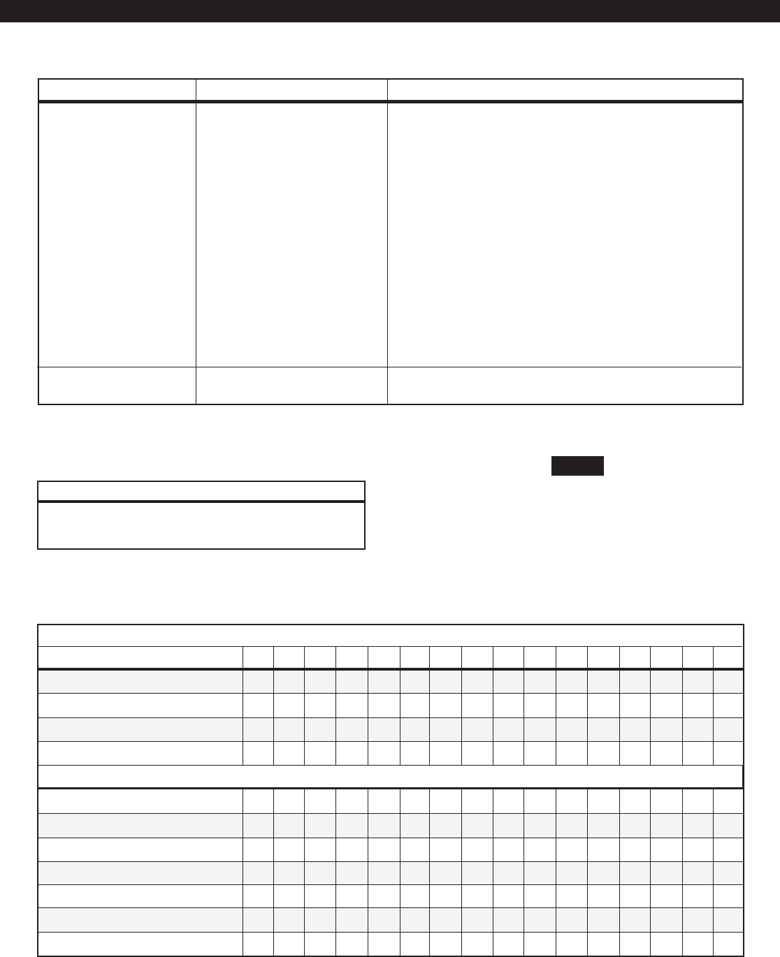
70
INSTALLER LEVEL PROGRAMMING
Burglar Bell (Steady/Pulsed) - determines the operation of the
Bell Output or Other Bell Output during a Burglar alarm.
Holdup Bell (Steady/Pulsed) - determines the operation of the
Bell Output or Other Bell Output during a Holdup alarm.
Auxiliary Bell (Steady/Pulsed) - determines the operation of the
Bell Output or Other Bell Output during an Auxiliary alarm.
Bell Test on Arm - if enabled, then the Bell Output or Other
Bell Output for an area will be activated for two seconds
when that area is armed in the AWAY mode.
Log Alarm Abort Events - if enabled, Abort Alarm events are
posted in the Event Log. (See Inst. Level Prog.- Prog.
Notes, Note 10).
Log Access Events - if enabled, the Keypad Access
Activated events will be posted in the Event Log. These
events are not reportable to the Central Station.
Print Access Only R/T - if enabled with a printer connected,
then only Keypad Access Activated events will be printed.
This does not affect the Event Log print command.
Sets the number of failed passcode entry attempts allowed
before a 50 second lockout for a particular Control Station.
System Attributes 00 to FF
(see the System
Attribute Table.)
Passcode Entry Lockout 0 = No Lock,
1 to 15 attempts
ITEM VALID RANGE DESCRIPTION
Alarm Bell operations only affect
the Bell Outputs. They do not af-
fect the associated Alarm Indica-
tor outputs.
NOTE
•
FIRST DIGIT
System Attribute Table
ENTER FOR:
••••••••
•• •• •• ••
•••• ••••
•• •••• ••
••••••••
••
•• ••••
•• •• •
••• •••••••
•
If the First Digit entered is 1, it must be entered as 01. A = 10; B = 11; C = 12; D = 13; E = 14; F = 15
•••• ••••
•
SECOND DIGIT
••••
••••
Fire Bell Table
0 = Steady 2 = Temporal
1 = Pulsed (March Time) 3 = Calif March Time
FIRST (Fire Bell 1) & SECOND (Fire Bell 2) DIGITS
0123456789ABCDE F
All Features Below Disabled
Log Alarm Abort Events
Log Access Events
Print Access Only Real Time
Burglar Bell Steady
Burglar Bell Pulsed
Holdup Bell Steady
Holdup Bell Pulsed
Aux Bell Steady
Aux Bell Pulsed
Bell Test on Arm

71
Loc Default Loc Default
Phone Lines [322] H-22 Dialer Types [331] H-11
Enable Skip Test [323] 0 CS1 Dial Attempts [332] 5
Power-up Comm Test [324] 0 CS2 Dial Attempts [333] 5
Disable Call Waiting [325] 0 Pager Dial Attempts [334] 1
Comm Test Time of Day (hr:min) [326: 327] 00:00 Pager Delay Time (sec) [335] 15
Days Between Comm Tests [328] 1 On-Hook Time (sec) [336] 5
Time Between Calls (sec) [329] 5 Off-Hook Time (sec) [337] 3
Trans Formats [330] H-33
Communicator Data Default Table
Communicator Data Description
INSTALLER LEVEL PROGRAMMING
The following table refers to programming locations
322 through 337:
Phone Lines 0 to 22
(see Phone Lines Table)
Enable Skip Test 0 = No
1 = Yes
Power-up Comm Test 0 = No
1 = Yes
Disable Call Waiting 0 = No
1 = Yes
Comm Test Time of Day 00:00 to 23:59 HH:MM
Days Between Comm Tests 0 = Disable, 1 to 255 days
Time Between Calls 0 to 255 seconds
Trans Formats 00 to 44
(see Trans Formats Table)
Dialer Types 00 to 22
(see Dialer Types Table)
CS1 Dial Attempts 1 to 15 attempts
CS2 Dial Attempts 1 to 15 attempts
Pager Dial Attempts 1 to 15 attempts
Pager Delay Time 0 to 255 seconds
On-Hook Time 1 to 15 seconds
& Off-Hook Time
ITEM VALID RANGE DESCRIPTION
First digit is used to enable phone line 1 for digital communicator
event reporting and to enable monitoring of phone line 1. The
second digit is used to enable phone line 2 for digital communica-
tor event reporting and to enable monitoring of phone line 2. If a
phone line is disconnected, turning off the monitoring of that line
will clear the PHONE LINE FAIL trouble condition.
Allows the auto comm test to be skipped if any signal has been
transmitted to the Central Station since the last auto comm test.
Causes a communicator test to be initiated immediately upon sys-
tem power up. Does not affect days between tests counter.
If enabled, the system will automatically dial *70D (Touchtone
only) prior to dialing a telephone number. This will temporarily
disable the Call Waiting beeps during a phone call.
Sets the hour and minute in military format for the auto commu-
nicator test.
Sets the time intervals in days for the auto communicator test. A
setting of 0 disables Automatic Comm Test Reporting. Days until
next comm test may be manually adjusted by Control Station. (See
Installer Level Programming - Days Until Next Comm Test).
Time in seconds between a failed dial attempt to a Central Station
and the next dial attempt.
First digit defines the transmission format used when the commu-
nicator dials the phone number for Central Station 1. Second digit
defines the transmission format used when the communicator di-
als the phone number for Central Station 2. (See Inst. Level Prog.
- Prog. Notes, Note 11).
First digit defines the type of dialing used on phone line 1. Second
digit defines the type of dialing used on phone line 2.
Maximum number of dial attempts when the communicator dials
the phone number for Central Station 1.
Maximum number of dial attempts when the communicator dials
the phone number for Central Station 2.
Total number of dial attempts when the communicator dials a Pager
phone number. All attempts will be used.
Time in seconds that the communicator waits after dialing before
blindly sending a pager message.
Before the communicator dials a phone number, it seizes the phone
line and goes off-hook for two seconds. It will then go back on-
hook for the On-Hook Time to disconnect an existing phone con-
nection. The communicator will then go back off-hook for the Off-
Hook Time to acquire dial tone before dialing.
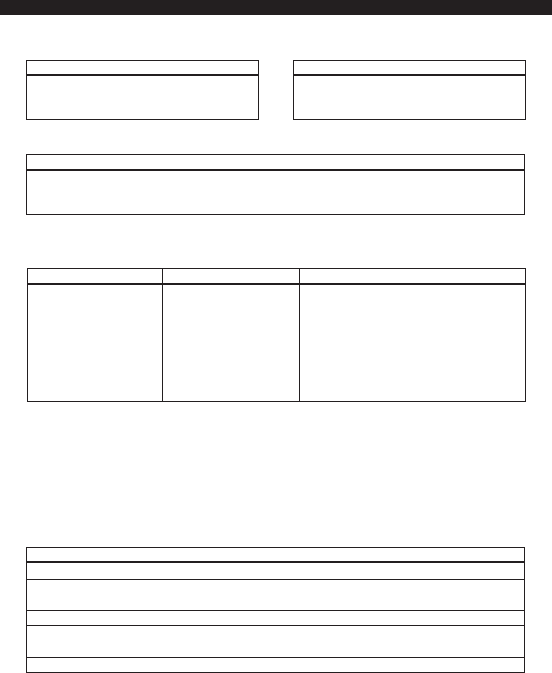
72
Communication Numbers Description
Event reporting assignments for each telephone num-
ber are programmed under the Installer Level Program-
ming - Area Event Reporting section. The assignment
All receivers listed functioned with the listed formats at time of testing. Modifications or programming changes may affect receiver
operation. Consult manufacturer of specific receiver for setup and operation.
RECEIVERS TRANSMISSION FORMAT TRANSMISSION SPEEDS (Pulse Reporting Only)
Ademco 685 3/1, 4/2, Contact ID 20B
FBI CP220 3/1, 4/2, Contact ID 20B - 40B
Osborne-Hoffman (Quick Alert) 3/1, 4/2, Contact ID 20B - 40B
Radionics 6000 3/1 20B - 40B
Radionics 6500 3/1, 4/2 20B - 40B
Silent Knight 9000 3/1, 4/2 20B - 40B
MLR-2DG 3/1, 4/2, Contact ID 20B - 40B
INSTALLER LEVEL PROGRAMMING
Receiver Compatibility Table
Loc Default
Central Station 1 Phone Number [338 - 357] all Fs
Central Station 2 Phone Number [358 - 377] all Fs
Area 1 Pager Phone Number [378 - 397] all Fs
Area 2 Pager Phone Number [398 - 417] all Fs
RPM/2 Pro Phone Number* [418 - 437] all Fs
Area 1 Pager Header Message [438 - 453] all Fs
Area 2 Pager Header Message [454 - 469] all Fs
Communication Number Default Table
Phone Lines Table
0 = Disabled
1 = Enabled
2 = Enabled with Line Monitor
FIRST (Phone Line 1) & SECOND (Phone Line 2) DIGITS
Transmission Formats Table
0 = Pulsed 20 Baud - Non Extended 3 = Contact ID
1 = Pulsed 20 Baud - Extended 4 = Non-Telco Contact ID
2 = Pulsed 40 Baud - Extended
FIRST (CS1) & SECOND (CS2) DIGITS
Dialer Types Table
0 = US Rotary North American Standard (60/40) make/break ratio pulses.
1 = Touchtone®Industry standard DTMF tones. Touchtone is a trademark of AT&T.
2 = Foreign Rotary 67/33 make break ratio pulses, typical of foreign countries.
FIRST (Phone Line 1) & SECOND (Phone Line 2) DIGITS
of telephone dialing options and reporting formats are
programmed under the Installer Level Programming -
Communicator Data Description section.
* Available for Call Back Command from RPM/2 Pro. Available for Call RPM in the future.
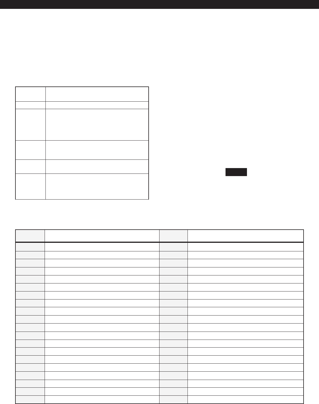
73
INSTALLER LEVEL PROGRAMMING
0 - 9 Numbers from 0 to 9 dial the appropriate
Touchtone® or pulse digit.
A Same as 0.
B Programming a B into any digit position
causes the communicator to produce a
Touchtone® * tone. Useful for unique appli-
cations such as voice mail, cellular, or pag-
ing applications.
C Programming a C into any digit position
causes the communicator to produce a
Touchtone® # tone.
D, E D = 3 second pause
E = 1 second pause
F An F may be programmed after the last digit
of a number to signify end of dialing. An F
entered as the first digit of a number disables
that number.
All five phone numbers allow up to 20 hex digits.
The two Pager Header Messages allow up to 16 hex
digits. See also Installer Level Programming - Pro-
gramming Account Codes and Telephone Number
Digits.
Dialed Digits Allowed
The paging network setup for
your area determines if your
pager will work with a pager
telephone number.
NOTE
Pager Telephone Numbers
When an event is sent to a pager, the events Area
Pager Phone Number is dialed. System events are
sent to the Area 1 Pager Phone Number. The com-
municator then waits the Pager Delay Time (see I.L.P.
Communicator Data Descr.) before blindly sending
a pager message. The pager message may consist
of up to 16 digits from the appropriate Pager Header
Message followed by a two digit code from the Pager
Event Table. Or, if the Pager Header Message is not
needed, put an F in its first digit and the appropriate
four digit account code is used in its place. The Pager
Event Table is also available on a wallet card.
Only one message is sent per phone call and the call
is made for the number of Pager Dial Attempts speci-
fied. There is no feedback from the pager, so pager
events do not affect the failed to communicate con-
dition.
2-DIGIT
CODE
11 Fire Alarm
12 Supervisory Alarm
13 Burglar Alarm
14 Holdup Alarm
15 Duress
16 Auxiliary Alarm
17 Critical Condition Monitor
18 Exit Alarm
21 Zone Trouble
22 Testing (Fire Zone)
23 Zone Bypassed
24 Unsuccessful Attempt to Access via Keypad
25 System Trouble
26 AC Power Failure
31 Alarm Restore
32 Zone Trouble Restore
33 Zone Unbypassed
35 System Trouble Restore
36 AC Power Restore
37 Central Station Comm Restore
41 Arm
42 Auto Arm Failed/Canceled
43 Auto Arm Delayed
44 Recent Closing
45 Disarm
46 Burglar Alarm Canceled
51 Latchkey Supervision
52 User On Premises
61 Comm Test
62 Comm Test (Not Normal)
63 Begin Installer Programming, Installer On Premise
64 End Installer/Remote Programming, Installer Off Premise
65 Remote Programming Failure
66 Call Home (Panic Key)
EVENT DESCRIPTION 2-DIGIT
CODE EVENT DESCRIPTION
Pager Event Table
74
INSTALLER LEVEL PROGRAMMING
SYSTEM AREA 1 AREA 2
Loc Default Loc Default Loc Default
Tel 1 Account No (4 Hex Digits) [470 - 473] 0000 [478 - 481] 0000 [486 - 489] 0000
Tel 2 Account No (4 Hex digits) [474 - 477] 0000 [482 - 485] 0000 [490 - 493] 0000
Fire Phone No. [494] 3
System Events Phone No. [495] 3
System Troubles Phone No. [496] 3
Burglar Phone No. [497] 3 [505] 3
Hold-up Phone No. [498] 3 [506] 3
Auxiliary Phone No. [499] 3 [507] 3
CCM Phone No. [500] 3 [508] 3
Zone Trouble/Restore Phone No. [501] 0 [509] 0
Zone Bypass/Restore Phone No. [502] 0 [510] 0
Open/Close Phone No. [503] 0 [511] 0
Supervision Phone No. [504] 0 [512] 0
Event Reporting Default Table
Event Reporting Description

75
Telephone 1 Account No.
Telephone 2 Account No.
Fire Phone No.
Note: These events are
reported using System
account codes only.
System Events Phone No.
Note: These events are
reported using System
account codes only.
System Troubles Phone No.
Note: These events are
reported using System
account codes only.
Burglar Phone No.
Hold-up Phone No.
Auxiliary Phone No.
Critical Condition Monitor
(CCM) Phone No.
Zone Trouble/Restore
Phone No.
Zone Bypass/Restore
Phone No.
Open/Close Phone No.
Supervision Phone No.
4 Hex Digits
4 Hex Digits
0 to 11
(See Phone Directors Table)
0 to 11
(See Phone Directors Table)
0 to 11
(See Phone Directors Table)
0 to 11
(See Phone Directors Table)
0 to 11
(See Phone Directors Table)
0 to 11
(See Phone Directors Table)
0 to 11
(See Phone Directors Table)
0 to 11
(See Phone Directors Table)
0 to 11
(See Phone Directors Table)
0 to 11
(See Phone Directors Table)
0 to 11
(See Phone Directors Table)
Account number used when dialing CS1 Phone Number or Pager.
(See Inst. Level Prog. - Prog. Notes, Note 11).
Account number used when dialing CS2 Phone Number.
(See Inst. Level Prog. - Prog. Notes, Note 11).
Directs which telephone number(s) to report Fire Alarms, Fire
Supervisories, and Restorals.
Directs which telephone number(s) to report system events.
Includes Keypad Lockout, Auto Comm Test, Begin & End In-
staller Local Programming, End Remote Programming, Remote
Programming Denied & Aborted.
Directs which telephone number(s) to report system events. In-
cludes Keypad Missing & Restoral, AC Failure & Restoral, Panel Low/
No Battery & Restoral, Bell Faults & Restoral, Comm Restoral, Ground
Fault & Restoral, Memory Error, Phone Line Faults & Restoral, RF
Jamming, RF Channel Clear and RF User Device Low Battery.
Directs which telephone number(s) to report Burglar Alarms,
Burglar Tamper, Exit Alarm, Recent Closing, Burglar Alarm Can-
celed, and Restorals.
Directs which telephone number(s) to report Holdup Alarms,
Duress, and Restorals.
Directs which telephone number(s) to report Auxiliary Alarms
and Restorals.
Directs which telephone number(s) to report Critical Condition
Monitoring events and Restorals.
Directs which telephone number(s) to report Zone Troubles and
Restorals.
Directs which telephone number(s) to report Zone Bypasses and
Restorals.
Directs which telephone number(s) to report Openings, Clos-
ings, Auto Arm Fail, Auto Arm Aborted, and Closing Extended.
Directs which telephone number(s) to report Latch Key Supervi-
sion, User on Premises, Secure Watch, and Secure Watch Re-
store.
The following table refers to programming locations
470 through 512:
ITEM VALID RANGE DESCRIPTION
INSTALLER LEVEL PROGRAMMING
Phone Directors Table
0 = Do Not Report
1 = CS1 Phone Only
2 = CS2 Phone Only
3 = CS1 Phone (CS2 Phone on Failure)
4 = CS2 Phone (CS1 Phone on Failure)
5 = CS1 Phone and CS2 Phone
6 = Pager Only
7 = CS1 Phone and Pager
8 = CS2 Phone and Pager
9 = CS1 Phone (CS2 Phone on Failure) and Pager
10 = CS2 Phone (CS1 Phone on Failure) and Pager
11 = CS1 Phone, CS2 Phone and Pager

76
INSTALLER LEVEL PROGRAMMING
The Zone Report Codes utilize programming loca-
tions 513 through 632. Each Zone has an alarm,
restore, bypass and trouble code. The restore may
be an alarm, trouble, or bypass restoral. A Zone
Trouble may result from one of the following conditions:
Wiring problem
Secure Watch Trouble
No Response from Zone Expander
Fire Trouble
(Fire zone bypassed or Fire zone in Walk Test)
Smoke Trouble
RF Point Not Reporting
RF Sensor Tamper
RF Point Low Battery
Zone Report Codes Description
These events will be posted and displayed differently
in the Event Log. If one of these events is reported
using a Pulsed format, then the standard Zone
Trouble report code will be used. If one of these
events is reported using Contact ID then a more
descriptive report code will be used.
Each report code requires a two digit entry. The first
digit sets the primary event code and the second
digit sets the extended code. (See Installer Level Pro-
gramming - Programming Report Codes). If a trans-
mission format other than a Pulsed format is used, it
is only necessary to program a value other than zero
into either digit to enable that event to be reported,
the correct transmitted data is automatically sent.

77
INSTALLER LEVEL PROGRAMMING
ALARM RESTORE BYPASS TROUBLE
Loc Default Loc Default Loc Default Loc Default
Zone 01 [513] H-31 [514] H-E3 [515] H-AB [516] H-F3
Zone 02 [517] H-32 [518] H-E3 [519] H-AB [520] H-F3
Zone 03 [521] H-33 [522] H-E3 [523] H-AB [524] H-F3
Zone 04 [525] H-34 [526] H-E3 [527] H-AB [528] H-F3
Zone 05 [529] H-35 [530] H-E3 [531] H-AB [532] H-F3
Zone 06✝[533] H-36 [534] H-E3 [535] H-AB [536] H-F3
Zone 07 [537] H-37 [538] H-E3 [539] H-AB [540] H-F3
Zone 08 [541] H-38 [542] H-E3 [543] H-AB [544] H-F3
Zone 09 [545] H-39 [546] H-E3 [547] H-AB [548] H-F3
Zone 10 [549] H-3A [550] H-E3 [551] H-AB [552] H-F3
Zone 11 [553] H-3B [554] H-E3 [555] H-AB [556] H-F3
Zone 12✝[557] H-3C [558] H-E3 [559] H-AB [560] H-F3
Zone 13 [561] H-3D [562] H-E3 [563] H-AB [564] H-F3
Zone 14 [565] H-3E [566] H-E3 [567] H-AB [568] H-F3
Zone 15 [569] H-3F [570] H-E3 [571] H-AB [572] H-F3
Zone 16 [573] H-61 [574] H-E6 [575] H-AB [576] H-F6
Zone 17 [577] H-62 [578] H-E6 [579] H-AB [580] H-F6
Zone 18 [581] H-63 [582] H-E6 [583] H-AB [584] H-F6
Zone 19 [585] H-64 [586] H-E6 [587] H-AB [588] H-F6
Zone 20 [589] H-65 [590] H-E6 [591] H-AB [592] H-F6
Zone 21 [593] H-66 [594] H-E6 [595] H-AB [596] H-F6
Zone 22 [597] H-67 [598] H-E6 [599] H-AB [600] H-F6
Zone 23 [601] H-68 [602] H-E6 [603] H-AB [604] H-F6
Zone 24 [605] H-69 [606] H-E6 [607] H-AB [608] H-F6
Zone 25 [609] H-6A [610] H-E6 [611] H-AB [612] H-F6
Zone 26 [613] H-6B [614] H-E6 [615] H-AB [616] H-F6
Zone 27 [617] H-6C [618] H-E6 [619] H-AB [620] H-F6
Zone 28 [621] H-6D [622] H-E6 [623] H-AB [624] H-F6
Zone 29 [625] H-11 [626] H-E1 [627] H-AB [628] H-F1
Zone 30 [629] H-12 [630] H-E1 [631] H-AB [632] H-F1
Zone Report Codes Default Table
✝ Not Available

78
CLOSE OPEN CLOSE OPEN
Loc Default Loc Default Loc Default Loc Default
User 01 [633] H-C1 [634] H-B1 User 26 [683] H-CF [684] H-BF
User 02 [635] H-C2 [636] H-B2 User 27 [685] H-CF [686] H-BF
User 03 [637] H-C3 [638] H-B3 User 28 [687] H-CF [688] H-BF
User 04 [639] H-C4 [640] H-B4 User 29 [689] H-CF [690] H-BF
User 05 [641] H-C5 [642] H-B5 User 30 [691] H-CF [692] H-BF
User 06 [643] H-C6 [644] H-B6 User 31 [693] H-CF [694] H-BF
User 07 [645] H-C7 [646] H-B7 User 32 [695] H-CF [696] H-BF
User 08 [647] H-C8 [648] H-B8 User 33 [697] H-CF [698] H-BF
User 09 [649] H-C9 [650] H-B9 User 34 [699] H-CF [700] H-BF
User 10 [651] H-CA [652] H-BA User 35 [701] H-CF [702] H-BF
User 11 [653] H-CB [654] H-BB User 36 [703] H-CF [704] H-BF
User 12 [655] H-CC [656] H-BC User 37 [705] H-CF [706] H-BF
User 13 [657] H-CD [658] H-BD User 38 [707] H-CF [708] H-BF
User 14 [659] H-CE [660] H-BE User 39 [709] H-CF [710] H-BF
User 15 [661] H-CF [662] H-BF User 40 [711] H-CF [712] H-BF
User 16 [663] H-CF [664] H-BF User 41 [713] H-CF [714] H-BF
User 17 [665] H-CF [666] H-BF User 42 [715] H-CF [716] H-BF
User 18 [667] H-CF [668] H-BF User 43 [717] H-CF [718] H-BF
User 19 [669] H-CF [670] H-BF User 44 [719] H-CF [720] H-BF
User 20 [671] H-CF [672] H-BF User 45 [721] H-CF [722] H-BF
User 21 [673] H-CF [674] H-BF User 46 [723] H-CF [724] H-BF
User 22 [675] H-CF [676] H-BF User 47 [725] H-CF [726] H-BF
User 23 [677] H-CF [678] H-BF User 48 [727] H-CF [728] H-BF
User 24 [679] H-CF [680] H-BF User 49 [729] H-CF [730] H-BF
User 25 [681] H-CF [682] H-BF User 50 [731] H-CF [732] H-BF
User Report Code Default Table
User Report Codes Description
The User Report Codes utilize programming loca-
tions 633 through 732. This data block is used to
program the opening and closing reports for each
user code.
Each report code requires a two digit entry. The
first digit sets the primary event code and the sec-
ond digit sets the extended code. (See Installer Level
Programming - Programming Report Codes). If a
transmission format other than a Pulsed format is
used, it is only necessary to program a value other
than zero into either digit to enable that event to be
reported, the correct transmitted data is automati-
cally sent.
The open and close report code is assigned to the
user, not the area. Some users may be assigned to
arm and disarm multiple areas. Any user with the
authority to arm and disarm multiple areas has the
same opening and closing report codes. However,
the Central Station can differentiate between areas
by the account code transmitted.
INSTALLER LEVEL PROGRAMMING

79
Loc Default Loc Default
Left Panic Key Report Code [733] H-19 AC Restore Report Code [754] H-EA
Center Panic Key Report Code [734] H-29 Low/No Battery Report Code [755] H-F9
Right Panic Key Report Code [735] H-49 Battery Restore Code [756] H-E9
Duress Code [736] H-99 Bell Fault Report Code [757] H-00
Keypad Lockout Code [737] H-00 Bell Restore Report Code [758] H-00
Burg Cancel Report Code [738] H-00 Telco Fault Report Code [759] H-00
Quick Arm Report Code [739] H-00 Telco Restore Report Code [760] H-00
Auto-Arm Code [740] H-00 Ground Fault Report Code [761] H-00
Auto-Arm Failed Code [741] H-00 Ground Restore Report Code [762] H-00
Keyswitch Closing Code [742] H-00 Comm Restore Report Code [763] H-00
Keyswitch Opening Code [743] H-00 Memory Error Report Code [764] H-00
Installer/RPM Closing Code [744] H-00 Local Program Begin Code [765] H-00
Installer/RPM Opening Code [745] H-00 Local Program End Code [766] H-00
Closing Extended Code [746] H-00 RPM End Report Code [767] H-00
Exit Alarm Code [747] H-00 RPM Denied Report Code [768] H-00
Recent Closing Code [748] H-00 RPM Abort Report Code [769] H-00
Latch Key Supervision Code [749] H-00 Missing Keypad Code [770] H-00
User on Premises Code [750] H-00 Restore Keypad Code [771] H-00
Comm Test Not Norm Code [751] H-F2 R F Jamming Report Code [772] H-00
Comm Test Report Code [752] H-F1 R F Channel Clear Report Code [773] H-00
AC Fail Report Code [753] H-FA RF User Device Low Battery Code [774] H-00
System Event Report Codes Default Table
INSTALLER LEVEL PROGRAMMING
System Report Codes Description
Each report code requires a two digit entry. The
first digit sets the primary event code and the sec-
ond digit sets the extended code. (See Installer Level
Programming - Programming Report Codes). If the
transmission format is anything other than a Pulsed
format, it is only necessary to program a value other
than zero into either digit to enable that event to be
reported, the correct transmitted data is automati-
cally sent.
Fire Panic Key Report Code 00 to FF Code sent for alarms activated by pressing the Left Panic key.
Holdup Panic Key Report Code 00 to FF Code sent for alarms activated by pressing the Center Panic key or an RF user device.
Aux/Med Panic Key Report Code 00 to FF Code sent for alarms activated by pressing the Right Panic key or an RF user device.
Duress Code 00 to FF Code sent for a duress (Authority Level 13) code arm or disarm.
Keypad Lockout Code 00 to FF Code sent when a Control Station is locked out due to failed passcode attempts.
Burg Cancel Report Code 00 to FF Code sent when an authorized user resets a burglar alarm after reporting and be-
fore the Burglar Bell Cutoff timer expires.
Quick Arm Report Code 00 to FF Code sent when an area is armed using Two-Button or Double Press Arming.
Auto-Arming Code 00 to FF Code sent when armed by scheduled program or Exit Arm.
Auto-Arm Failed Code 00 to FF Code sent when a scheduled arming is aborted or could not be completed.
The following table refers to programming locations
733 through 774:
ITEM VALID RANGE DESCRIPTION

80
Keyswitch Closing Code 00 to FF Code sent when an area is armed by keyswitch zone.
Keyswitch Opening Code 00 to FF Code sent when an area is disarmed by keyswitch zone.
Installer/RPM Closing Code 00 to FF Code sent when an area is armed by RPM or the installer at a Control Station.
Installer/RPM Opening Code 00 to FF Code sent when an area is disarmed by RPM or the installer at a Control Station.
Closing Extended Code 00 to FF Code sent when the scheduled closing time is extended.
Exit Alarm Code 00 to FF Code sent in addition to a burglar alarm event if the alarm occurs when the exit time expires.
Recent Closing Code 00 to FF Code sent in addition to a burglar alarm event if the alarm occurs within two minutes
after exit time expires.
Latch Key Supervision Code 00 to FF Code sent when the Latch Key code is not entered during the programmed time window.
User on Premises Code 00 to FF Code sent when the User on Premises (Authority Level 12) passcode is entered to
disarm the system or perform the access operation.
Comm Test Not Norm Code 00 to FF Code sent at the comm test time-of-day in place of the comm test report when a
trouble condition is present. If this report code is set to 00, a normal comm test
event is transmitted.
Comm Test Report Code 00 to FF Code sent at the comm test time-of-day when no trouble conditions are present. Transmitted
at power-up, if Test On Power-Up is enabled. Transmitted for Manual Comm Test, if pro-
grammed. (See Inst. Level Prog.- Communication Data Description). Implies proper operation
of the communicator and the telephone line.
AC Fail Report Code 00 to FF Code sent when the control has lost the primary AC input. The delay time before
this report is transmitted is located in Installer Level Programming - Global System
Options Description.
AC Restore Report Code 00 to FF Code sent when the AC primary power has been restored.
Low Battery Report Code 00 to FF Code sent when the control detects a low battery voltage reading of 11.3 VDC or less.
Battery Restore Code 00 to FF Code sent when the low battery condition has been restored.
Bell Fault Report Code 00 to FF Code sent when the control panel detects a Bell Fault. Contact ID will distinguish
between Bell 1 and Bell 2 faults.
Bell Restore Report Code 00 to FF Code sent when a Bell Fault trouble restores. Contact ID will distinguish between Bell 1
and Bell 2 restores.
Telco Fault Report Code 00 to FF Code sent when the control panel detects a Telco Fault. Contact ID will distinguish
between Phone Line 1, Phone Line 2 and Non-Telco faults.
Telco Restore Report Code 00 to FF Code sent when a Telco Fault trouble restores. Contact ID will distinguish between
Phone Line 1, Phone Line 2 and Non-Telco restores.
Ground Fault Report Code 00 to FF Code sent when the control panel detects a Ground Fault.
Ground Restore Report Code 00 to FF Code sent when a Ground Fault trouble restores.
Comm Restore Report Code 00 to FF When the control is unsuccessful in reporting an event, the fail to communicate
(local trouble) displays. If a subsequent report of any type is successful, the control
also reports this code.
Memory Error Report Code 00 to FF Code sent when the internal memory check finds an unauthorized change in the
value of one or more of the programming options.
Local Prog Begin Code 00 to FF Code sent when a program function map is initiated at the control site.
Local Prog End Code 00 to FF Code sent after programming mode is terminated at the installation site. This occurs
255 seconds after exiting programming mode or by holding the CLEAR key for three
seconds.
RPM End Report Code 00 to FF Code sent when an RPM session has been completed normally.
RPM Denied Report Code 00 to FF Code sent when an unauthorized RPM session is attempted (i.e.: improper ID code
or access device).
RPM Abort Report Code 00 to FF Code sent when an RPM session is aborted. If an alarm event requiring a report to
the Central Station occurs during an RPM session, the control may abort the session
to report the event.
Missing Keypad Code 00 to FF Code sent when a supervised Control Station is removed or fails to respond to sys-
tem polling.
Restore Keypad Code 00 to FF Code sent when a missing Control Station is restored to the data bus.
RF Jamming Report Code 00 to FF Code sent when an RF Gateway detects an RF Jamming condition.
RF Channel Clear Code 00 to FF Code sent when an RF Gateway detects an RF Jamming condition has cleared.
RF User Device Low Battery 00 to FF Code sent when an RF Gateway detects a Low Battery condition on one of its User
Code Devices.
INSTALLER LEVEL PROGRAMMING

81
INSTALLER LEVEL PROGRAMMING
Area Schedules Description
Automatic Arming
If automatic arming is enabled, the control produces
a warning signal at the appropriate Control Station(s)
once every minute beginning ten minutes prior to
the event. During this warning, the same Control
Station(s) may display a visual indication of the im-
pending action and the amount of time remaining.
This allows the user ample warning to exit or over-
ride the impending action. Auto Arming time may
be extended by one hour during each ten minute
warning period (but not past midnight) using the
Delay Auto Arming function. The user can also abort
the scheduled arming for that day through User Level
programming. (See the appropriate User Guide).
Auto Arming arms the control in the AWAY, STAY, or
NIGHT mode with normal exit time.
Latch Key Schedules
A Latch Key User ID is used to determine which user
passcode must be entered on selected Latch Key
Days. The user passcode must be entered within a
time window. If the user passcode is not entered
during the Time Window, a Latch Key Supervision
event will be posted in the Event Log to be reported.
For example, if Monday is a Latch Key Day and the
Latch Key Time for Monday is 14:30 with a thirty minute
Time Window and the Latch Key User ID is not en-
tered between 14:00 and 15:00 hours, then a Latch
Key Supervision event will be posted at 15:00 hours.
The Latch Key Time Window can-
not cross over the Midnight
boundary. During the Time Win-
dow, the Control Station will
chime once a minute until the user
passcode is entered or the Time
Window has expired, whichever
comes first.
NOTE
AREA 1 AREA 2
Loc Default Loc Default
Scheduled Arm Mode [775] 0 [808] 0
Scheduled Arm Days [776] H-00 [809] H-00
Arm Time Sun (hr:min) [777:778] 00:00 [810:811] 00:00
Arm Time Mon (hr:min) [779:780] 00:00 [812:813] 00:00
Arm Time Tues (hr:min) [781:782] 00:00 [814:815] 00:00
Arm Time Wed (hr:min) [783:784] 00:00 [816:817] 00:00
Arm Time Thurs (hr:min) [785:786] 00:00 [818:819] 00:00
Arm Time Fri (hr:min) [787:788] 00:00 [820:821] 00:00
Arm Time Sat (hr:min) [789:790] 00:00 [822:823] 00:00
Latch Key User ID [791] 0 [824] 0
Latch Key Days [792] H-00 [825] H-00
Latch Key Window (min) [793] 0 [826] 0
Latch Time Sun (hr:min) [794:795] 00:00 [827:828] 00:00
Latch Time Mon (hr:min) [796:797] 00:00 [829:830] 00:00
Latch Time Tues (hr:min) [798:799] 00:00 [831:832] 00:00
Latch Time Wed (hr:min) [800:801] 00:00 [833:834] 00:00
Latch Time Thurs (hr:min) [802:803] 00:00 [835:836] 00:00
Latch Time Fri (hr:min) [804:805] 00:00 [837:838] 00:00
Latch Time Sat (hr:min) [806:807] 00:00 [839:840] 00:00
Area Schedules Default Table

82
If the First Digit entered is 1, it must be entered as 01. A = 10; B = 11; C = 12; D = 13; E = 14; F = 15
Scheduled Arming Mode 0 = AWAY, 1 = STAY, 2 = NIGHT Determines the Auto Arm mode.
Scheduled Arming Days 00 to FF Selects the days of the week the system automatically arms.
(see the table below for a complete
description of each values activation)
Sunday Arming Time 00:00 to 23:59 The time for Auto Arming on Sunday.
Monday Arming Time 00:00 to 23:59 The time for Auto Arming on Monday.
Tuesday Arming Time 00:00 to 23:59 The time for Auto Arming on Tuesday.
Wednesday Arming Time 00:00 to 23:59 The time for Auto Arming on Wednesday.
Thursday Arming Time 00:00 to 23:59 The time for Auto Arming on Thursday.
Friday Arming Time 00:00 to 23:59 The time for Auto Arming on Friday.
Saturday Arming Time 00:00 to 23:59 The time for Auto Arming on Saturday.
Latch Key User ID 0 = disable, User 1 to 50 Determines the user passcode that has Latch Key Supervision.
Latch Key Days 00 to FF (see Scheduled Arming Selects the days of the week that Latch Key Supervision is
and Latch Key Days Table.) performed.
Latch Key Time Window 0 to 255 minutes Time in minutes (+/-) the Latch Key User Code may be
entered.
Sunday Latch Key Time 00:00 to 23:59 The time, (+/-) the Time Window, the Latch Key user
passcode must be entered on Sunday.
Monday Latch Key Time 00:00 to 23:59 The time, (+/-) the Time Window, the Latch Key user
passcode must be entered on Monday.
Tuesday Latch Key Time 00:00 to 23:59 The time, (+/-) the Time Window, the Latch Key user
passcode must be entered on Tuesday.
Wednesday Latch Key Time 00:00 to 23:59 The time, (+/-) the Time Window, the Latch Key user
passcode must be entered on Wednesday.
Thursday Latch Key Time 00:00 to 23:59 The time, (+/-) the Time Window, the Latch Key user
passcode must be entered on Thursday.
Friday Latch Key Time 00:00 to 23:59 The time, (+/-) the Time Window, the Latch Key user
passcode must be entered on Friday.
Saturday Latch Key Time 00:00 to 23:59 The time, (+/-) the Time Window, the Latch Key user
passcode must be entered on Saturday.
The following table refers to programming locations
775 through 840:
INSTALLER LEVEL PROGRAMMING
ITEM VALID RANGE DESCRIPTION
0123456789ABCDE F
All Days Below Disabled
Thursday
Friday
Saturday
All Days Below Disabled
Sunday
Monday
Tuesday
Wednesday
•
FIRST DIGIT
Scheduled Arming and Latch Key Days Table
ENTER FOR:
••••••••
•• •• •• ••
•••• ••••
SECOND DIGIT
••••• •••
••••
•••
••
•• ••••
•
•
•• ••
•
•••
•
83
Installer Passcode 0000 to 9999 The installer passcode is the only passcode that may program the entire
Function Map. See Installer Level Programming - User Data Description
for a description of the other functions that may be performed.
2nd Call Timer 0 - 255 seconds Time in seconds for the answering machine bypass time window. This allows
the remote programmer to bypass an answering machine by making two
calls to the premises. The first call must ring three times or less and not be
answered. The answering machine bypass time window starts ten seconds
after the last ring of the first call. If the first ring of the second call occurs
within the answering machine bypass time window, the panel answers the
second call on the first ring. Remote Programming must be enabled and
Auto-Answer Ring count must be non-zero.
Auto Answer Ring Count 0 - 15 rings Sets the number of rings that must occur before the panel automatically
answers the telephone for operation with RPM/2 Pro. A ring count of 0
disables automatic answering, but manual connection may still be used. If
Remote Programming is not enabled, then the auto-answer ring count is
ignored and the panel never answers.
Enable RPM 0 = No Enables operation of the control with the RPM/2 Pro package.
1 = Yes Connection to RPM/2 Pro may only be achieved using Phone Line 1.
Enable Power Up Program 0 = No A quick way to enter program mode upon power up. Pressing the 9 key
and entering 9999 within the first 60 seconds after power up enters the
control into Installer Level Programming mode. Consider disabling this
feature for anti-takeover.
Lockout Local Program 0 = No This is provided for anti-takeover protection. If it is enabled, the
installer passcode is limited as noted in Installer Level Programming - User
Data Description. A user may still be able to perform user level program-
ming and RPM/2 Pro will be fully operational. Do not enable this unless an
RPM/2 Pro account has been established for the control.
INSTALLER LEVEL PROGRAMMING
Programming Options
This section deals with the attributes of the Remote
Programming Manager Software. Before program-
ming the specific functions, it is important to un-
derstand the following:
Abort: During a remote programming session, the
control is fully functional and can detect and an-
nunciate alarms locally. The control aborts a session
with RPM/2 Pro to report alarm events.
Datalock: As a provision of anti-takeover, the con-
trol does not permit local programming of the ac-
count numbers and telephone numbers, or the Re-
store Factory Defaults option to operate when an
agency code has been established and programmed
by the RPM/2 Pro software. Other installer program-
The following table refers to programming locations
841 through 849:
Loc Default
Installer Passcode [841 - 844] 9632
Call 2 Timer (sec) [845] 0
Auto Answer Ring Count [846] 0
Enable RPM [847] 1
Enable Power Up Program [848] 0
Lockout Local Program [849] 0
Programming Options Default Table
ming changes are still allowed. When the Datalock
(agency code) is set, the Control Station emits an error
tone if any attempt is made to change an account
number or a phone number or to default the control.
ITEM VALID RANGE DESCRIPTION
1 = Yes
1 = Yes

84
Programming Notes
Note 1: Restarting Exit Time
If an exit time is counting down from an AWAY arm-
ing, the exit time may be automatically restarted
once to reduce false alarms.
The exit time will be restarted if a Perimeter (arm in
STAY mode and arm in NIGHT mode) Burglar zone
is violated anytime during the last ten seconds of
exit time.
If the exit time is not due to an Exit Arm or a Sched-
uled Arming, then the exit time will be restarted if it
expires and a Perimeter (Arm in STAY mode and Arm
in NIGHT mode) Burglar zone has not been violated
during the exit time (i.e.: nobody went out the door).
Note 1A: Entry Delay Times
The Entry Delay Times (Entry Delay 1 and Entry De-
lay 2) of an area work together to provide a more
secure Entry Delay Time. For example, Entry Delay
1 may be programmed as 4 minutes and Entry De-
lay 2 may be programmed as 1 minute. If Entry De-
lay 1 (4 min.) is started and counts down to 2 min-
utes remaining when an armed Delay 2 zone is vio-
lated, then the Entry Delay Time is reduced to the
more secure Entry Delay 2 time (1 minute remain-
ing). However, if the Entry Delay Time counts down
below the Entry Delay 2 Time (i.e. to 30 seconds
remaining), then no adjustment is made. Entry De-
lay Time is only decreased, it is never increased.
Note 2: Entry Time versus Pre-Alarm Warning
Time
Assuming Exit, Entry and Pre-Alarm Warning Times
are inactive, a violation of an armed Burglar zone
will cause the following actions depending on the
areas arm level and the type of Burglar zone:
Note 3: Exit Arm
An Exit Arm is intended to automatically arm an area
ten minutes after the premises are vacated. An Exit
Arm will only be attempted when it is enabled for
an area and the area is disarmed and not in alarm.
The end user can disable the Exit Arm feature on a
day-to-day basis (see the appropriate User Guide).
If a Disable Exit Arming is performed, the Exit Arm
will be disabled until midnight.
When a Delay Burglar zone restores from a viola-
tion, the areas Exit Arm timer is started at ten min-
utes. During this time, the Control Station may dis-
play a visual indication of the impending action and
the amount of time remaining. An audible warning
signal will occur at two minutes until arming and at
one minute until arming. When any Burglar zone is
violated, the areas Exit Arm timer is halted. If a Delay
zone restores from a violation while the timer is run-
ning, the timer is restarted at ten minutes. If an
Instant or Follower Burglar zone restores from a vio-
lation, the timer is halted.
If the timer expires (i.e.: ten minutes of no Burglar
zone activity following a Delay zone restoration),
then the system attempts to arm the area in the
AWAY mode. If Force-Arming is enabled, then a
Force-Arm may occur if needed. If the arming is
successful, then Exit time is started and an Auto-Arm
event is logged to be reported. If the arming can-
not be completed, then nothing will happen.
Note 4: Force-Arming
If Force-Arming is enabled for an area, then an arm-
ing from a keyswitch zone, an Exit Arming or a
Scheduled Arming will be Force-Armed if necessary.
Note 5: LED Control Stations
The Secondary Area setting is ignored for LED Con-
trol Stations since they cannot provide area infor-
INSTALLER LEVEL PROGRAMMING
AWAY STAY STAY INSTANT NIGHT NIGHT INSTANT
Instant Burglar Instant Alarm Pre-Alarm Warning Pre-Alarm Warning Pre-Alarm Warning Pre-Alarm Warning
Time Time Time Time
Delay Burglar Entry Time Entry Time Instant Entry Time Instant
Follower Burglar Pre-Alarm Warning Pre-Alarm Warning Pre-Alarm Warning Pre-Alarm Warning Pre-Alarm Warning
Time Time Time Time Time

85
INSTALLER LEVEL PROGRAMMING
mation and prompts. Therefore, LED Control Sta-
tions cannot have a Secondary Area.
Note 6: Verifying or Self-Verifying Burglar Zones
If an armed Verifying Burglar zone is violated, then a
forty second Verification Timer is started. If the timer
expires and the zone that started it is still in viola-
tion, then the zones violation is verified. If another
armed Burglar zone is violated while the timer is still
running, then that violation verifies the first zones
violation.
If an armed Self-Verifying Burglar zone is violated,
then a forty second Verification Timer is started. If
the Timer expires and the zone is still in violation,
then the zones violation is verified. If another armed
Burglar zone is violated while the Timer is still run-
ning, then that violation verifies the first zones vio-
lation. If the same armed Burglar zone is violated a
second time while the Timer is still running, then
the zones violation is verified.
If the area is armed such that a violation from the
zone would normally cause an instant alarm:
when the zone is first violated, nothing happens.
when the violation is verified, an instant alarm
occurs.
if the Verification Timer expires without the vio-
lation being verified, then nothing happens.
If the area is armed such that a violation from the
zone would normally cause an Entry Time or Pre-
Alarm Warning Time Delay:
when the zone is first violated, the Delay Timer
is started.
if the violation is verified while the Delay Timer is
still running, then the Delay Timer continues as
normal.
if the Verification Timer expires while the Delay
Timer is still running and the violation has not
been verified, then the time continues. If the
Delay Timer expires and no zones are violated
from the Delay Time, then nothing happens.
if the Delay timer expires before the Verification
timer expires and the violation has not been veri-
fied, then nothing will happen until either the vio-
lation is verified or the Verification Timer expires.
if the violation is verified after the Delay Timer
has expired, then an instant alarm occurs.
if the Verification Timer expires after the Delay
Timer has expired without the violation being
verified, then nothing happens.
Common Area Burglar zones cannot be programmed
as verifying or self-verifying, but they can verify a veri-
fying or self-verifying zone from Area 1 or Area 2 (see
Operating the System - Introduction).
Note 7: Sentry Test Burglar Zones
If a Burglar zone has Sentry Test enabled, then each
time the zone is disarmed, it must be tested before it
can be armed again. A test consists of violating the
zone from a restored state and then restoring it again.
If the zone has not been tested, then it appears as a
faulted zone and is displayed as Zone Untested
from the View Info key. An untested zone cannot be
armed and its area is therefore not ready to arm. If
the zone is bypassable, then it may be bypassed to
prevent testing. Force-Arming should not be enabled
on systems with Sentry Test Burglar Zones.
Note 8: Zone Activation of Bell Output and
Keypad Sounders
The Bell Output on Alarm attribute determines
whether the Bell Output for the zones area activates
due to an alarm from the zone. It does not affect the
activation of any other programmable outputs, in-
cluding an associated Alarm output.
This attribute is used for the Other Bell Output if the
Zone Type is Burglar, Holdup, Auxiliary or Burglar
Tamper. It is also used for the Fire Bell 1 Output if
the Zone Type is Fire or Verified Fire and there is no
Water Flow zone. Otherwise, it is ignored. If Water
Flow zones are used, then Fire Bell 2 activates on
alarms from Water Flow zones and Fire Bell 1 acti-
vate activates on all alarms from Fire and Verified
Fire zones and from the Left Panic key.
The Keypad Sounder on Alarm attribute generally
determines whether the Control Station sounders
activate due to an alarm from the zone. This attribute
is only used for Keypad Sounders if the Zone Type is
Burglar, Holdup or Auxiliary. It does not affect the
activation of any programmable outputs for these
zones. This attribute is also used for the Fire Bell 2
Output if the Zone Type is Fire or Verified Fire and
there is no Water Flow zone. Otherwise, it is ignored.
Keypad sounders activate on all alarms from Fire,

86
INSTALLER LEVEL PROGRAMMING
Water Flow and Verified Fire zones and from the Left
Panic key, as well as from Burglar Tamper and Fire
Supervisory zones. They never activate from the
other Zone Types.
If a Holdup zone is programmed with neither Bell
Output on Alarm nor Keypad Sounder on Alarm,
then an alarm from the zone will be invisible on the
Control Stations.
Note 9: Secure Watch
The Secure Watch attribute may only be used with
Burglar, Critical Condition Monitor, Non-Alarm,
Universal, and Universal Logged zones. It is ignored
for all other zone types.
If a Burglar zone has Secure Watch enabled, then
the Secure Watch only applies when the zone is dis-
armed and not bypassed. Whenever the zone is vio-
lated, disarmed or unbypassed, the zones Secure
Watch timer is reset to the programmed time. If
that timer expires and the zone is disarmed and not
bypassed, then a Secure Watch Trouble event is
posted for the zone to be reported. The trouble
condition is not displayed on the keypad and it does
not prevent the area from being armed. A Secure
Watch Trouble Restore event is posted for the zone
to be reported if the zone is then either violated,
armed, or bypassed.
If a Critical Condition Monitor, Non-Alarm, Universal,
or Universal Logged zone has Secure Watch enabled,
then the Secure Watch only applies when the zone is
not bypassed. When the zone is violated or unbypassed,
the zones Secure Watch timer is reset to the pro-
grammed time. If that timer expires and the zone is
not bypassed, then a Secure Watch Trouble event is
posted for the zone to be reported. The trouble con-
dition is not displayed on the keypad. A Secure Watch
Trouble restore event is posted for the zone to be re-
ported if the zone is either violated or bypassed.
While a zone has a Secure Watch Trouble condition,
its corresponding Secure Watch signaling device
(programmable output) will stay ON steady.
Note 10: Delay Before Dial Time
The Delay Before Dial Time is used as the time that
a user has after a Burglar, Holdup, or Auxiliary Alarm
from a zone has occurred to silence the alarm with a
disarm and abort the Alarm event.
If the Delay Before Dial Time is not zero and the alarm
is silenced before the Delay Before Dial Time expires,
then no Alarm events are posted to be reported. If this
occurs and Log Alarm Aborted Events is enabled, then
Alarm Aborted events are posted for each zone that
went into alarm, but they are not reported.
If the Delay Before Dial Time is zero or if the Delay
Before Dial Time expires before the alarm is silenced
with a disarm, then the Alarm events are posted to
be reported. If the alarm is a Burglar Alarm and the
alarm is silenced with a disarm before the Burglar
Bell Cutoff Timer expires, then a Cancel Alarm
event is logged to be reported.
If an alarm in a Control Stations Primary or Sec-
ondary area is in Delay Before Dial Time, then
when the OFF CANCEL key is pressed on the Con-
trol Station, all alarms in the Control Stations Pri-
mary and Secondary areas are muted until the
Delay Before Dial Time expires. While an alarm
is muted, the Control Stations do not produce the
alarm tone for the alarm and the Bell Output(s)
are silent. The muting of an alarm does not affect
the operation of programmed outputs. If the De-
lay Before Dial Time expires without the alarm
being silenced, then the Control Stations resume
the alarm tone and the Bell Output(s) re-activate.
The alarm cut-off timer(s) continue to count while
the alarm is muted.
Note 11: Transmission Formats
If the Data Format is Pulsed 20 Baud - Non-Ex-
tended, then the number of digits in the account
code determines how events are reported. If the
fourth digit of the account code is 0, then events
are reported in the 3/1 Non-Extended format. If
the fourth digit of the account code is not 0, then
events are reported in the 4/1 Non-Extended for-
mat. Only the first digit of the report code is sent.
If an account code digit or the first digit of the
report code is 0, then that digit is transmitted as
an A. Each event is reported in two rounds for
verification.
For the 3/1 Non-Extended format, the first three dig-
its of the account code and the first digit of the re-
port code are transmitted in a round. For the 4/1
Non-Extended format, all four digits of the account
code and the first digit of the report code are trans-
mitted in a round.

87
INSTALLER LEVEL PROGRAMMING
If the Data Format is Pulsed 20 Baud - Extended
or Pulsed 40 Baud - Extended, then the number
of digits in the account code must be four (4) digits.
Both digits of the report code are sent. If an ac-
count code digit or one of the report code digits is
0, then that digit is transmitted as an A. Each event
is reported in two rounds for verification.
For the 4/2 Extended format, then all four digits of
the account code and both digits of the report code
are transmitted in a round.
If the Data Format is Contact ID, then all four dig-
its of the account code are sent. The report code is
only used to determine if the event is sent or not.
The reports are generated from a Contact ID report
table. This is an Ademco developed format.
If the Data Format is Non-Telco Contact ID, then
all four digits of the account code are sent. The re-
port code is only used to determine if the event is
sent or not. The reports are generated from a Con-
tact ID report table. The report will be sent to an
interface device over the data bus. The interface
device will send an acknowledgment to the system
upon successful transmission of an event. The asso-
ciated Central Station telephone number will not be
used, but its first digit must not be an F. If the in-
terface device responds back with a transmission fail-
ure or if the interface device loses the event, the
system will view it as a failed dial attempt. If the
interface device is not responding on the data bus,
a Non-Telco Failure condition will be posted and
the system will not try to report through the inter-
face. This may cause a Comm Failure condition to
occur or the event may be reported using another
phone number.
If the Pager option is used, up to 16 digits of the
Pager Header Message and a 2-digit Pager Event
Message are sent. (If the Pager Header Message is
not used, a 4-digit Account Code and a 2-digit Pager
Event Message are sent). The telephone number will
be dialed for the number of dial attempts pro-
grammed and the pager message will be blindly sent
each time. There will be no feedback and, there-
fore, no failed to communicate.
The Pager option is perfect for the parent who works
late and wants to know if their child arrived home
safely. When the child disarms the system, the par-
ent is paged. Since arming/disarming reports are
programmed for each user, the system can be pro-
grammed to only page when the childs user
passcode is used or when a passcode with the User
on Premises authority level is used. The pager op-
tion can also be used with the Latch Key Supervi-
sion report to page the parent when the child does
not come home when expected.
Note 12: Powering Up While Armed
If either area is armed when the panel powers up,
violations from all the burglar zones are ignored for
three minutes. This allows all armed PIRs to stabilize
without causing false alarms.
Note 13: Universal Outputs
A Universal output may be assigned to any combi-
nation of areas and is controlled by the Universal
timer or keypad in each of the areas. When a Uni-
versal or Universal Logged zone in an area is vio-
lated, the areas Universal timer will begin a count-
down. If the Universal Output Time is set to zero (0),
then the areas Universal timer will turn ON. To turn it
OFF, use the ENTER + Key #2 secondary function.
If the Universal Output Time is not set to zero (0),
then the ENTER + Key #2 secondary function will
override the Universal Output timer. For example, if
the timer is running when the function is performed,
then the output will be turned OFF and the timer
will halt. A new zone activation will turn the output
ON and re-start the timer. If the timer is not run-
ning when the function is performed, then the func-
tion will turn the output ON and subsequent zone
violations will be ignored until after the output is
turned OFF by performing the function again.
A Universal output will go ON STEADY when any of
its areas have a Universal timer that is either running
or ON. If the Universal Output Time is 0, only one
area should be used to control a Universal output.
Otherwise, an area will not be able to turn the out-
put OFF if another area has turned it ON.
Note 14: Lamp Trigger Outputs
A Lamp Trigger output will change state (ON to OFF
or OFF to ON) for the Control Stations Primary area
when the ENTER + Key #1 secondary function is
performed. If the output is turned ON with the EN-

88
TER + Key #1 secondary function and then an arm-
ing occurs, the output will turn OFF when the Exit
Time expires.
Note 15: Access and Quick Access Outputs
An Access output will be controlled by the Access
operations (0 + passcode) performed on any of its
Control Stations or from RPM. A Quick Access out-
put will be controlled by pressing ENTER + Key #3.
If a Control Station is used to toggle an Access or Quick
Access output between ON and OFF, then it should be
the only Control Station controlling that output. Oth-
erwise, you may not be able to turn the output OFF if
another Control Station has turned it ON.
Note 16: Water Flow Zone
If a zone is programmed as Water Flow, then Fire
Bell 2 shall be dedicated to the Water Flow zone and
Fire Bell 1 shall be dedicated to the other Fire zones.
Note 17: Bypassable Zones - Shunting Fire Zones
All zones may be programmed as Bypassable. If a
Fire, Verified Fire, Water Flow or Fire Supervisory Zone
is bypassable and is bypassed, a fire trouble condi-
tion occurs and is reported and the trouble tone is
sounded. The condition remains until the zone is
unbypassed. If the zone is violated when it is
unbypassed, the trouble tone is resounded and a
smoke reset must be performed to clear the trouble
condition.
INSTALLER LEVEL PROGRAMMING

89
Left Panic Key Fire Alarm 1115 500 + Keypad (1 - 6)
Zone Fire Alarm 1110 Zone (1 - 30)
Zone Water Flow Alarm 1113 Zone (1 - 30)
Zone Fire Supervisory 1200 Zone (1 - 30)
Zone Burglar Alarm 1130 Zone (1 - 28)
Zone Burglar Tamper 1137 Zone (1 - 28)
Center Panic Key or RF User Device Holdup Alarm 1120 500 + Keypad (1 - 6)
Zone Holdup Alarm 1120 Zone (1 - 28)
Duress 1121 User (1 - 50)
Right Panic Key or RF User Device Auxiliary Alarm 1100 500 + Keypad (1 - 6)
Zone Auxiliary Alarm 1100 Zone (1 - 28)
Zone CCM Alarm 1150 Zone (1 - 28)
Zone Non-Alarm 1163 Zone (1 - 28)
Zone Fire Trouble 1373 Zone (1 - 30)
Zone Fire Test Mode Begin 1604 Zone (1 - 30)
Zone Burglar Trouble 1370 Zone (1 - 28)
Zone Holdup Trouble 1370 Zone (1 - 28)
Zone Auxiliary Trouble 1370 Zone (1 - 28)
Zone Other Trouble 1370 Zone (1 - 28)
Secure Watch Trouble 1641 Zone (1 - 28)
Zone No Response on Bus 1333 Zone (13 - 29)
RF Point Not Reporting 1381 Zone (13 - 28)
Smoke Trouble 1393 Zone (13 - 30)
RF Sensor Tamper 1383 Zone (13 - 28)
RF Point Low Battery 1384 Zone (13 - 28)
Zone Burglar Bypass 1573 Zone (1 - 28)
Zone Holdup Bypass 1572 Zone (1 - 28)
Zone Auxiliary Bypass 1572 Zone (1 - 28)
Zone Other Bypass 1570 Zone (1 - 28)
CONTACT ID FORMATS
Digital Communicator Table For Contact ID
Formats
This section cross-references many of the reporting
options and equivalent codes sent by Sentrol-manu-
factured controls when transmitting in the Contact
ID formats.
Simplified example of data sent in Contact ID format:
SSSS 18 Q XYZ AA CCC
SSSS = 4 decimal digit subscriber #
18 = Contact ID que for automation systems
Q = Event qualifier; 1 = new event or opening;
3 = new restore or closing; 6 = previously
reported event
XYZ = Event code (3 decimal digits)
AA = Area number (00 for system events)
CCC = Zone, sensor, or user # (3 decimal digits)
EVENT TYPE CID CODE EVENT SOURCE

90
Zone Fire Alarm Restore 3110 Zone (1 - 30)
Zone Water Flow Restore 3113 Zone (1 - 30)
Zone Fire Supervisory Restore 3200 Zone (1 - 30)
Zone Burglar Alarm Restore 3130 Zone (1 - 28)
Zone Burglar Tamper Restore 3137 Zone (1 - 28)
Zone Holdup Alarm Restore 3120 Zone (1 - 28)
Zone Auxiliary Alarm Restore 3100 Zone (1 - 28)
Zone Critical Condition Monitor Alarm Restore
3150 Zone (1 - 28)
Zone Non-Alarm Restore 3163 Zone (1 - 28)
Zone Fire Trouble Restore 3373 Zone (1 - 30)
Zone Fire Test Mode End 3604 Zone (1 - 30)
Zone Burglar Trouble Restore 3370 Zone (1 - 28)
Zone Holdup Trouble Restore 3370 Zone (1 - 28)
Zone Auxiliary Trouble Restore 3370 Zone (1 - 28)
Zone Other Trouble Restore 3370 Zone (1 - 28)
Secure Watch Trouble Restore 3641 Zone (1 - 28)
Zone No Response Restore 3333 Zone (13 - 29)
RF Point Reporting 3381 Zone (13 - 28)
Smoke Trouble Restore 3393 Zone (13 - 30)
RF Sensor Tamper Restore 3383 Zone (13 - 28)
RF Point Low Battery Restore 3384 Zone (13 - 28)
Zone Burglar Bypass Restore 3573 Zone (1 - 28)
Zone Holdup Bypass Restore 3572 Zone (1 - 28)
Zone Auxiliary Bypass Restore 3572 Zone (1 - 28)
Zone Other Bypass Restore 3570 Zone (1 - 28)
User AWAY Arm from Keypad 3401 User (1 - 50)
User STAY or NIGHT Keypad Arm 3456 User (1 - 50)
Quick AWAY Arm from Keypad 3408 No Data
Quick STAY or NIGHT Keypad Arm 3408 No Data
Keyswitch Arm 3409 Zone (1 - 28)
Installer Arm 3400 No Data
RPM/2 Pro Arm 3407 No Data
Auto Arm 3403 No Data
Auto Arm Failed 1455 No Data
Auto Arm Aborted 3455 User (1 - 50)
Closing Extended 3464 User (1 - 50)
Exit Alarm 1374 Zone (1 - 28)
Recent Closing 3459 User (1 - 50)
User Disarm from Keypad 1401 User (1 - 50)
Keyswitch Disarm 1409 Zone (1 - 28)
Installer Disarm 1400 No Data
RPM/2 Pro Disarm 1407 No Data
Latch Key Supervision 1642 User (1 - 50)
User on Premises 1458 User (1 - 50)
Keypad Locked-out 1300 500 + Keypad (1 - 6)
Keypad Missing 1330 500 + Keypad (1 - 6)
Keypad Missing Restore 3330 500 + Keypad (1 - 6)
CONTACT ID FORMATS

91
Burglar Alarm Canceled 3406 User (1 - 50)
Auto-Comm Test (Not Normal) 1608 No Data
Auto-Communicator Test 1602 No Data
Manual Communicator Test 1601 No Data
AC Failure 1301 No Data
AC Restore 3301 No Data
Panel Low/No Battery 1302 No Data
Panel Battery Restore 3302 No Data
Bell or Fire Bell 1 Fault 1321 No Data
Bell or Fire Bell 1 Restore 3321 No Data
Fire Bell 2 Fault 1322 No Data
Fire Bell 2 Restore 3322 No Data
Ground Fault 1310 No Data
Ground Restore 3310 No Data
Communication Restore 3354 No Data
Memory Error 1303 No Data
Begin Installer Local Program 1627 No Data
End Installer Local Program 1628 No Data
End Remote Programming 3412 No Data
Remote Programming Denied 1413 No Data
Remote Programming Aborted 1412 No Data
RF Jamming 1381 No Data
RF Channel Clear 3381 No Data
RF User Device Low Battery 1384 User (1 - 30)
Phone Line 1 Failure 1351 No Data
Phone Line 1 Restore 3351 No Data
Phone Line 2 Failure 1352 No Data
Phone Line 2 Restore 3352 No Data
Non-Telco Failure 1353 No Data
Non-Telco Restore 3353 No Data
CONTACT ID FORMATS
92
UL has established certain requirements which per-
tain to the installation, use, and programming of
this equipment. The local Authority Having Jurisdic-
tion (AHJ) and/or UL may have other requirements
which apply to the installation of this system that
are not detailed in this manual. It is the responsibil-
ity of the installing dealer to check with the AHJ and/
or UL before installing this system. The following
pages detail guidelines that must be followed in or-
der to comply with the UL listings as stated above.
UL Notes In This Manual
Key 0 (Access) - The control has not been in-
vestigated to UL 294 Access Control System re-
quirements.
Unsupervised Burglary Zones - UL does not per-
mit the use of unsupervised zones.
UL Notes About Program
Functions
Entrance Delay Time (1 and 2) - Maximum of
45 seconds.
AWAY Exit Delay Time - Maximum of 60 sec-
onds.
Burglar Alarm Cutoff Time - Four minutes mini-
mum for household BA/FA and 15 minutes for
Underwriters Laboratories (UL)
Listing
This control is listed by Underwriters Laboratories
(UL) as follows:
Household Burglary (Grade A) UL 1023
Household Fire UL 985
Central Station Burglary (Grade C) UL 1610/1635
Central Station Burglary (Grade B) UL 1610/1635
Home Health Care Signaling Equipment UL 1637
Local Burglary (Grade A) UL 609
Police Station Burglary Connection (Grade A) UL 365
Control Units For Fire Protective Signaling Systems UL 864
UL Programming Requirements
APPLICATION LISTING
commercial burglar alarm and police station con-
nected burglar alarm system.
Fire Cutoff Time - minimum of five (5) minutes.
Communicator Enable - Local or police station
connected burglar alarm installations: The com-
municator must be enabled.
Days Between Comm. Tests - Commercial instal-
lations: automatic test performed every 24 hours.
Time Between Dial Attempts - UL certified ac-
counts: no more than 45 seconds between at-
tempts.
Dial Type - Will not be programmed for foreign
pulse.
Dial Attempts Before Shutdown - Five dial at-
tempts minimum, ten dial attempts maximum.
Arming/Disarming Reports - This function will
be enabled by programming report codes.
Low Battery Reporting - This function will be en-
abled by programming a report code for Grade
A Local Burglar, Grade A Police Connected, and
Grade B and C Central Station Burglar installa-
tions.
Two Button/Double Press Arming - These func-
tions will be disabled. Four digit passcodes will
be used.
Enable Force Arming - This function will be dis-
abled.
Enable Bypassing - This function will be disabled.
Burglar Alarm Output - Will be programmed to
STEADY.
Fire Alarm Output - Will be programmed to TEM-
PORAL.
UL REQUIREMENTS

93
Burglar Loop Audible Lockout - This function will
be disabled.
Enable Bell Test Upon Arming - This function will
be enabled for Grade A Local Central Station
Connected installations.
Enable Keypad Sounder for BA Zones - The sys-
tem will have an audible alarm output upon
alarm.
Auto-Arming - This function will be disabled.
Burglar zones will not be programmed as Veri-
fying or Self-Verifying.
RF User Devices must be assigned to User
Passcodes 1 - 30.
UL Notes About Zone Planning
Burglar Loops - Will be defined as Alarm on
Open/Alarm on Short.
Fire, Holdup, and Auxiliary Emergency Zones -
Will not be defined as bypassable.
Special Functions/Alarms - Burglar zones will
have an audible output.
Medical Emergency - At least one Control Sta-
tion will be used as part of the system.
UL Notes About RF Devices
For UL Burglary and Home Health Care installations
with wireless devices, an output programmed as
Audible Trouble is required. This output will be
silenced with an OFF + passcode, but will reactivate
for 5 seconds at 4 hour intervals if a wireless device
has a low battery or a wireless point has been tam-
pered.
UL REQUIREMENTS

94
NOTES
Notes
______________________________________________________________________
______________________________________________________________________
______________________________________________________________________
______________________________________________________________________
______________________________________________________________________
______________________________________________________________________
______________________________________________________________________
______________________________________________________________________
______________________________________________________________________
______________________________________________________________________
______________________________________________________________________
______________________________________________________________________
______________________________________________________________________
______________________________________________________________________
______________________________________________________________________
______________________________________________________________________

95
ZX440F Operating Instructions
Refer to the ZX440F Installation/Programming Manual for more information, Part # 64812853.
NORMAL STANDBY CONDITION TROUBLE CONDITION
Keypad displays A1 READY TO ARM Keypad displays A1 READY TO ARM plus
All switches are UP any trouble conditions
Integral sounder and keypad sounder are silent Any trouble conditions will be annunciated
on the LCD display along with OFF TO
ALARM CONDITION SILENCE
Keypad displays either FIRE ALARM, Integral sounder sounds a steady
HOLDUP ALARM, MEDICAL/AUXILLARY ALARM signal and the keypad sounder sounds a
or a combination of these and OFF TO SILENCE fast, intermittent signal
is also displayed
Keypad sounder sounds a slow intermittent signal TROUBLE SILENCED
Indicating circuits are ON Press the OFF CANCEL button once and
enter the 4 digit passcode
ALARM SILENCE The sounder will then turn OFF, but the
Press the OFF CANCEL button once and trouble message will remain on the screen
enter the 4 digit passcode until the trouble is no longer present
The keypad will display A1 READY TO ARM, BELL
1 SILENCED, and/or BELL 2 SILENCED SUPERVISORY ALARM SIGNAL
To restore the bells to normal condition, press 7 Integral sounder sounds a steady signal
followed by the 4 digit passcode and the keypad sounder sounds a slow,
intermittent signal.
RESET SMOKE OPERATED Keypad displays SUPERVISORY ALRM
Initiating circuit power removed (smoke detectors reset) Indicating circuits are NOT activated
System restored to normal unless initiating devices are
NOT reset SUPERVISORY TROUBLE SIGNAL
Integral sounder sounds a steady
FIRE ALARM BELL DISCONNECT SWITCH signal and the keypad sounder
(For Maintenance Use Only) sounds a fast, intermittent signal
Disconnects local zone alarms from indicating Keypad displays SUPERVISORY TRBL
circuits Indicating circuits are not activated
Keypad will indicate BELL FAULT, OFF TO
SILENCE
Integral sounder sounds a steady signal and the
keypad sounder sounds a fast, intermittent signal
The following applies to Household Fire Warning Systems only:
TESTING - In a Household Fire Warning System, Test Monthly. Disconnect the AC power source
during testing. If, after testing, a low battery condition exists, replace the batteries.
This equipment should be installed in accordance with the National Fire Protection Associations
Standard 72 (NFPA, Batterymarch Park, Quincy, MA 02269). Printed information describing
proper installation, operation, testing, maintenance, evacuation planning and repair service is to
be provided with this equipment.
WARNING:
Owners instruction notice: Not to be removed by anyone except occupant.
FOR SERVICE CONTACT:
A Product of Sentrol 1510 Tate Blvd. SE, Hickory, NC 28603 Sales 800-547-2556 Technical Service 800-800-2027
Remove this page, frame and mount adjacent to control unit. 64812854C

96

97
Part 68 Notification
This equipment complies with Part 68 of the Fed-
eral Communications Commissions (FCC) rules. All
connections to the telephone network must be made
through standard telephone company plugs and
jacks, RJ-31X or equivalent, in such a manner as to
allow for easy and immediate disconnection of the
equipment. If the connecting cord is unplugged
from the jack there shall be no interference to the
telephone equipment still connected to the tele-
phone network.
The FCC registration number and Ringer Equivalence
Number (REN) can be found printed on the wiring
connection label located inside the Control Box En-
closure. If requested, provide this information to
your telephone company. The REN is useful to de-
termine the quantity of devices that may be con-
nected to your telephone line and still have all of
those devices ring when your number is called. In
most, but not all areas, the sum of the RENs of all
devices should not exceed five (5.0).
In the unlikely event that the equipment should ever
fail to operate properly, it should be disconnected
from the telephone jack to determine if the prob-
lem is with the telephone network or with the equip-
ment. If a problem is found with the equipment,
leave disconnected until it is repaired or replaced.
In the unlikely event that the equipment should ever
cause harm to the telephone network, the telephone
company may temporarily discontinue your service.
If possible, they will notify you in advance. How-
ever, if advance notice isnt practical, the telephone
company may temporarily discontinue service with-
out prior notification. In the case of temporary dis-
continuance, the telephone company shall promptly
notify the telephone subscriber who will be given
the opportunity to correct the situation. The cus-
tomer also has the right to bring a complaint to the
FCC if he feels the disconnection is not warranted.
Your telephone company may make changes in its
facilities, equipment, operations, or procedures that
could affect the proper operation of your equipment.
If they do, you will be given advance notice so as to
give you an opportunity to maintain uninterrupted
service.
FCC COMPLIANCE
FCC Compliance
You should notify the telephone company if this
equipment is removed from the premises and the
telephone jack is no longer needed.
Part 15 Notification
This equipment has been tested and found to com-
ply with the limits for a Class B digital device, pursu-
ant to part 15 of the FCC Rules. These limits are
designed to provide reasonable protection against
harmful interference when the equipment is oper-
ated in a residential environment. This equipment
generates, uses, and can radiate radio frequency
energy and, if not installed and used in accordance
with the instruction manual, may cause harmful in-
terference to radio communications. However, there
is no guarantee that interference will not occur in a
particular installation. If this equipment does cause
harmful interference to radio or television reception,
which can be determined by turning the equipment
off and on, the user is encouraged to try to correct
the interference by one or more of the following
measures:
Reorient or locate the receiving antenna.
Increase the separation between the equipment
and receiver.
Connect the equipment into an outlet on a circuit
different from that to which the receiver is con-
nected.
Consult the dealer or an experience radio/TV tech-
nician for help.
CAUTION: Changes or modifications not ex-
pressly approved by the manufacturer could void
the users authority to operate the equipment.
Canadian Notice
The Canadian Department of Communications la-
bel identifies certified equipment. This certification
means that the equipment meets certain telecom-
munications network protective, operational and
safety requirements. The Department does not guar-
antee the equipment will operate to the users satis-
faction. Before installing this equipment, users
should ensure that it is permissible to be connected
to the facilities of the local telecommunications com

98
Limitations
The ZX440F is part of a system designed to warn
against unauthorized entry or of other situations.
However, it is not a guarantee of protection against
the occurrence of those events. Any alarm system is
subject to compromise or failure to warn for various
reasons. Unauthorized access can be gained through
unprotected points or by disarming or bypassing
protected points. Sensing devices are power driven
and will not operate without power. Telephone lines
over which alarm signals are transmitted may be out
of service or rendered inoperable by an intruder.
Smoke detectors have limitations and cannot detect
all types of fires, or sense smoke which is out of the
effective range of the detector.
All Rights Reserved
No part of this publication may be reproduced,
stored in a retrieval system, or transmitted in any
form, or by any means - electronic, mechanical,
photocopying, recording, or otherwise without the
prior written permission of the manufacturer. The
material in this publication is for information pur-
poses and subject to change without notice. The
manufacturer assumes no responsibility for any er-
rors which may appear in this publication. Printed
in USA
SPECIAL NOTE referencing use of the
word Fire in this manual.
Use of this control for fire detection and/or annun-
ciation may not be permitted by certain states, coun-
ties, municipalities, or local jurisdiction. It is the re-
sponsibility of the installing alarm company to check
with their local AHJ (Authority Having Jurisdiction)
or State Fire Marshals office prior to using this con-
trol for fire detection.
pany. The equipment must also be installed using
an acceptable method of connection. In some cases,
the companys inside wiring associated with a single
line individual service may be extended by means
of a certified connector assembly (telephone exten-
sion cord). The customer should be aware that com-
pliance with the above conditions may not prevent
degradation of service in some situations. Repairs
to certified equipment should be made by an au-
thorized Canadian maintenance facility designated
by the supplier. Any repairs or alterations made by
the user to this equipment, or equipment malfunc-
tions, may give the telecommunications company
cause to request the user to disconnect the equip-
ment. Users should ensure for their own protection
that the electrical ground connections of the power
utility, telephone lines and internal metallic water
pipe system, if present, are connected together. This
precaution may be particularly important in rural ar-
eas.
CAUTION: Users should not attempt to make
such connections themselves, but should contact
the appropriate electric inspection authority, or
electrician, as appropriate.
The LOAD NUMBER (LN) assigned to each terminal
device denotes the percentage of the total load to
be connected to a telephone loop which is used by
the device, to prevent overloading. The termina-
tion on a loop may consist of any combination of
devices subject only to the requirement that the to-
tal of the Load Numbers of all the devices does not
exceed 100. The LOAD NUMBER for the system is 2.
This equipment is a Class B Digital apparatus which
complies with the radio interference regulations, CRC
c. 1374.
FCC COMPLIANCE
See Page 36 for listing information
This Product is Listed by
UNDERWRITERS LABORATORIES INC.
and Bears the Mark:

99

100
64812853C
SENTROL
PO Box 2904, 1510 Tate Blvd. SE
Hickory, NC 28603
Tel.: 503.692.4052 Fax: 503.691.7566
U.S. & Canada: 800.547.2556
Technical Service: 800.800.2027
FaxBack: 800.483.2495
SENTROL CONTROLS GROUP
Sentrol reserves the right
to change specifications
without notice.
©1998 Sentrol
