Intercontinental Technologies F22-24E0032 Industrial Radio Remote Control Transmitter User Manual F22 Manual Rev 3 030104
Intercontinental Technologies Ltd Industrial Radio Remote Control Transmitter F22 Manual Rev 3 030104
User Manual

TELECRANE F22 Radio Remote Controls
Product Manuals
for
Handheld and Joystick Models
August 1, 2004
Revision 3.0.1
Intercontinental Technologies, Ltd.
558-2 Plate Drive
East Dundee, IL 60118
Phone: (847) 426-9597
Fax: (847) 426-9724
www.telecrane.com

FCC and Industry Canada Approval Information
The following information applies to transmitters:
This device complies with part 15 of the FCC Rules and RSS-210 of Industry
Canada. Operation is subject to the following two conditions: (1) This device may
not cause harmful interference, and (2) this device must accept any interference
received, including interference that may cause undesired operation.
Changes or modifications not expressly approved by Intercontinental
Technologies, Ltd. could void the user’s authority to operate equipment.
Ce dispositif est conforme aux normes CNR-210 d’Industrie Canada et la partie 15
des règles de la FCC. L’utilisation de ce dispositif est autorisée seulement aux
conditions suivantes: 1) il ne doit pas produire de brouillage et 2) l’utilisateur du
dispositif doit être prêt à accepter tout brouillage radioelectrique reçu, même si ce
brouillage est susceptible de compromettre le fonctionnement du dispositif .
This equipment has been tested and found to comply with the limits for a Class A
digital device, pursuant to Part 15 of the FCC Rules. These limits are designed to
provide reasonable protection against harmful interference when the equipment is
operated in a commercial environment. This equipment generates, uses, and can
radiate radio frequency energy and, if not installed and used in accordance with the
instruction manual, may cause harmful interference to radio communications.
Operation of this equipment in a residential area is likely to cause harmful
interference in which case the user will be required to correct the interference at his
own expense.
The following information applies to receivers:
Models F22-2D, F22-2D1, F22-2S, F22-2S1, F22-4D, F22-4D1, F22-4S, F22-4S1,
F22-6D, F22-6D1, F22-6S, F22-6S1, F22-12D, F22-10D1, F22-12S, F22-10S1,
F22-J:

Intercontinental Technologies, Ltd.
F22 Series Industrial Radio Remote Controllers: Product Manuals i
Table of Contents
Part 1: Operator’s Manual
Chapter 1 Warranty ............................................................................................................. 1
1.1 Warranty ............................................................................................................................... 1
1.2 Warranty Period .................................................................................................................... 1
1.3 Warranty Service .................................................................................................................. 1
1.4 Disclaimers ........................................................................................................................... 1
1.5 Warranty Contact Information.............................................................................................. 2
Chapter 2 Safe Operation....................................................................................................3
2.1 Emergency Procedures.......................................................................................................... 3
2.2 General Safety Information................................................................................................... 3
2.3 Installation Safety ................................................................................................................. 3
2.4 Operational Safety ................................................................................................................ 3
2.5 Safety When Performing User Maintenance ........................................................................ 4
Chapter 3 Overview of Parts and Features .........................................................................5
3.1 Large Chassis Mini-Style Transmitter.................................................................................. 5
3.2 Small Chassis Mini-Style Transmitter.................................................................................. 6
3.3 N1-Style Transmitter ............................................................................................................ 6
3.4 Typical Receiver for Handheld Models................................................................................ 7
3.5 Transmitter for the Model F22-J Joystick Controller ........................................................... 8
3.6 Receiver for the Model F22-J Joystick Controller................................................................ 9
Chapter 4 Operation of the F22 Series Industrial Radio Remote Controller .....................11
4.1 Normal Operation of the Handheld and Joystick Models................................................... 11
4.2 Special Functions of Handheld Models .............................................................................. 14
4.3 Special Functions of Joystick Models................................................................................. 15
Chapter 5 User Maintenance.............................................................................................17
5.1 Safety Aspects of User Maintenance .................................................................................. 17
5.2 Unusual Alarms .................................................................................................................. 17
5.3 Battery Changing Procedure (Handheld Models)............................................................... 17
5.4 Battery Changing Procedure (Joystick Models) ................................................................. 17
Chapter 6 Basic Troubleshooting ......................................................................................19
6.1 Reliability............................................................................................................................ 19
6.2 Self-Diagnostics and Error Codes....................................................................................... 19
6.3 User Troubleshooting.......................................................................................................... 19
Chapter 7 Safe Installation ................................................................................................ 21
7.1 Emergency Procedures........................................................................................................ 21
7.2 General Safety Information................................................................................................. 21
7.3 Installation Safety ............................................................................................................... 21
Chapter 8 Installation......................................................................................................... 23
8.1 Transmitter Installation....................................................................................................... 23
8.2 Receiver Installation ........................................................................................................... 23
8.3 Installation of Optional Accessories ................................................................................... 24

Intercontinental Technologies, Ltd.
ii F22 Series Industrial Radio Remote Controllers: Product Manuals
Chapter 9 Programming By Computer...............................................................................25
9.1 Overview............................................................................................................................. 25
Chapter 10 Function Settings...............................................................................................27
10.1 Description.......................................................................................................................... 27
10.2 F22 Series Handheld Transmitter Function Settings .......................................................... 27
10.3 F22 Series Joystick Transmitter Function Settings............................................................. 30
10.4 F22 Handheld Series Receiver Function Settings............................................................... 31
10.5 F22-J Receiver Function Settings ....................................................................................... 32
Chapter 11 Alarm Codes......................................................................................................35
Chapter 12 Principles of Operation of Major Subcomponents.............................................39
12.1 Transmitter.......................................................................................................................... 39
12.2 Receiver .............................................................................................................................. 40
Chapter 13 Customer-Specific Information ..........................................................................43
13.1 Serial Numbers and Security Codes ................................................................................... 43
13.2 Function Settings ................................................................................................................ 43
Chapter 14 Product Technical Sheets .................................................................................45
14.1 F22 Series Systems ............................................................................................................. 45
14.2 F22 Transmitter and Receiver Part Numbers...................................................................... 46
14.3 F22 Series: Accessories ...................................................................................................... 46
14.4 Extended Antenna Kit......................................................................................................... 47
14.5 Technical and Programming Sheets.................................................................................... 48

Intercontinental Technologies, Ltd.
F22 Series Industrial Radio Remote Controllers: Product Manuals iii
Table of Figures
F
IGURE
1: F22-12D T
RANSMITTER
....................................................................................................... 5
F
IGURE
2: F22-6D T
RANSMITTER
......................................................................................................... 6
F
IGURE
3: F22-10S1 T
RANSMITTER
..................................................................................................... 6
F
IGURE
4: T
YPICAL
R
ECEIVER FOR
H
ANDHELD
M
ODELS
(
FRONT AND BACK
) ....................................... 7
F
IGURE
5: F22-J J
OYSTICK
T
RANSMITTER
(
TOP AND BOTTOM
).............................................................. 8
F
IGURE
6: F22-J R
ECEIVER
(
FRONT AND BACK
) .................................................................................... 9
F
IGURE
7: EMS B
UTTON AND
S
TART
K
EY
.......................................................................................... 12
F
IGURE
8: E
NCODER
/B
UTTON
PCB ..................................................................................................... 39
F
IGURE
9: T
RANSMITTER
RF M
ODULE
............................................................................................... 39
F
IGURE
10: LED P
RINTED
C
IRCUIT
B
OARD ON
J
OYSTICK
R
ECEIVER
................................................. 40
F
IGURE
11: L
OCATION OF
R
UN
/T
EST
S
WITCH IN
R
ECEIVER FOR
H
ANDHELDS
.................................... 41
F
IGURE
12: L
OCATION OF
R
UN
/T
EST
S
WITCH IN
R
ECEIVER FOR
J
OYSTICK
......................................... 42
F
IGURE
13: P
ROGRAMMING
S
HEET
L
EGEND
........................................................................................ 48

Intercontinental Technologies, Ltd.
iv F22 Series Industrial Radio Remote Controllers: Product Manuals
THIS PAGE INTENTIONALLY LEFT BLANK

Intercontinental Technologies, Ltd.
Chapter 1 Page 1 of 87
Part 1: Operator’s Manual
Chapter 1 Warranty
1.1 Warranty
Intercontinental Technologies, Ltd. (ITL) guarantees that this product meets its published
specifications at the time of shipment.
1.2 Warranty Period
This equipment is warranted against defects in material and manufacturing for a period of one year
from the date of shipment. During the warranty period, ITL will repair or replace defective
components at no charge, if the failure of the product was due to defective material or
manufacturing.
1.3 Warranty Service
For warranty service, this product must ultimately be returned to ITL. The buyer must pay shipping
charges to the ITL service facility, and ITL will pay return shipping charges. Warranty service on
F22 units shall be provided by ITL only and ITL will not be responsible for service or repair costs
charged by third parties.
Your Distributor is:
Your ITL service facility is located at:
558-2 Plate Drive
East Dundee, IL 60118
phone: (847) 426-9597
1.4 Disclaimers
• ITL will not be liable for any damage to the warranted product, and no other warranty is
expressed or implied, except as explicitly described.
• ITL does not warranty any consumable parts, including batteries, fuses, buttons, relays, and
transmitter and receiver cases.
• This warranty does not include damage caused by improper installation (including ignoring
environmental specifications), improper or insufficient maintenance, any modifications,
improper operation, or improper software interfacing.
• The remedies provided herein are the buyer’s sole and exclusive remedies. ITL shall not be liable
for any direct, indirect, special, incidental or consequential damages.

Intercontinental Technologies, Ltd.
Page 2 of 87 Chapter 1
1.5 Warranty Contact Information
Please contact us at the address below for further help or if you have any
questions:
Intercontinental Technologies
558-2 Plate Drive
East Dundee, IL 60118 USA
Phone: 847-426-9597
Fax: 847-426-9724
Or Call Us Toll Free at (800) 382-3558
Intercontinental Technologies, Ltd.
Chapter 2 Page 3 of 87
Chapter 2 Safe Operation
Emergency Procedure
In case of emergency, perform these steps IN ORDER:
1. Press the Red STOP Button.
2. Turn the Green Rotary Key Switch to the OFF position and remove the key from
the transmitter.
3. Switch off the main power to the crane.
4. Contact your distributor or installer.
NOTE: Read ALL safety information before you operate this
product.
2.1 Emergency Procedures
If the F22 unit detects an error or system fault, it will issue an emergency STOP command and
deactivate all systems programmed for a STOP command. It is therefore important to install the F22
system correctly so that if it detects a fault, it can perform an emergency stop and the crane will shut
down safely.
2.2 General Safety Information
This manual is intended for the user as a general reference only. Please consult your
distributor for installation or assistance with specific technical issues. In an industrial
environment, safety must always be a top priority. Persons responsible for installation, operation,
and maintenance must make certain that both their actions and the equipment on which they work
are safe. This chapter includes a list of safety rules that must be followed when working with
TELECRANE products, as well as cranes in general. This list is not intended to be all-inclusive.
General industrial safety rules must always be followed. If there is any doubt about how to proceed,
always take the safest course of action.
2.3 Installation Safety
Only qualified personnel should install this product. For installation instructions and safety
information, refer to Part 2 of this manual.
2.4 Operational Safety
• Operating any piece of equipment in an industrial facility can be dangerous; therefore, provide
adequate training to operators of cranes that use this equipment.
• At least once each shift, check the amount of power remaining in the transmitter batteries (see
Section 4.1.3, “Checking Battery Power”). If it is low, change all four batteries before beginning
operation. Operating the unit with excessively discharged batteries can be unsafe.

Intercontinental Technologies, Ltd.
Page 4 of 87 Chapter 2
• If the transmitter battery power becomes insufficient, the transmitter will send out an Emergency
Stop signal (EMS). This signal will stop all actions previously set to shut down when a STOP
signal is received. The LED on the transmitter will illuminate red continuously and the buzzer on
the transmitter will buzz continuously until the batteries are removed. If this occurs, replace all
four batteries before using the product again.
• The magnetic safety key should be removed from the transmitter whenever it is not in use and
should only be issued to authorized personnel.
• All TELECRANE F22 Radio Remote Controls are tested before they leave the factory.
However, they should not be used in dangerous situations or in a manner such that damage might
result.
• Although the transmitter is very durable and weather-resistant, precautions should always be
taken to limit its exposure to weather, physical impact, and corrosives.
• After use, or if the unit will not be used for a long interval, turn off the power to the crane and
remove the magnetic safety key from the transmitter.
• Remove the batteries from the transmitter if the transmitter will not be used for two weeks or
longer.
• Transmitters that are not in use, including spare transmitters, should be secured to prevent
accidental operation.
• Before each shift, check that the limit switches on the crane function correctly.
• Before each shift, check that the movement of the crane corresponds to the button being pressed
on the transmitter.
• Do not use the product during lightning storms or high electrical interference conditions.
2.5 Safety When Performing User Maintenance
Before performing any maintenance on this product, review Chapter 5, “User Maintenance.”
Intercontinental Technologies, Ltd.
Chapter 3 Page 5 of 87
Chapter 3 Overview of Parts and Features
This Chapter describes the major parts and features of the F22 Series Industrial Radio Remote
Controller.
F22 Series radio remote controls are available in different styles to meet different needs. The two
basic configurations are handheld and joystick.
Handheld controllers are available in two configurations: “Mini-Style” and “N1-Style.” The Mini-
Style handhelds are new, advanced designs that are sleek and compact. They are easily held and
operated using one hand. The Mini-Style is available in two different chassis sizes: Large and
Small. Mini-Style transmitters are pictured in Sections 3.1 and 3.2.
N1-Style transmitters are designed for more severe service and include a heavy-duty chassis. They
are recognizable by their larger round buttons. N1-Style model numbers end in “1.” An N1-Style
transmitter is pictured in Section 3.3.
Both handheld models are available in different sizes and configurations, and can be customized to a
specific application. Both styles of transmitters utilize a similar receiver, pictured in Section 3.4.
The Joystick controller provides advanced functions and extended customization in a compact, two-
joystick configuration. The Joystick transmitter and receiver are pictured in Sections 3.5 and 3.6.
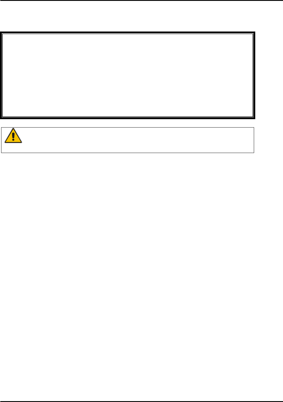
3.1 Large Chassis Mini-Style Transmitter
The following models are available in the
large chassis Mini-Style:
• F22-12D
• F22-12S
Figure 1 is a picture of the F22-12D, a Large
Chassis Mini-Style transmitter.
Figure 1: F22-12D Transmitter
Intercontinental Technologies, Ltd.
Page 6 of 87 Chapter 3
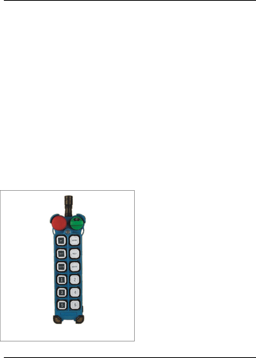
3.2 Small Chassis Mini-Style Transmitter
The following models are available in the small
chassis Mini-Style:
• F22-2S
• F22-2D
• F22-4S
• F22-4D
• F22-6S
• F22-6D
Figure 2 is a picture of the F22-6D, a Small Chassis
Mini-Style transmitter.
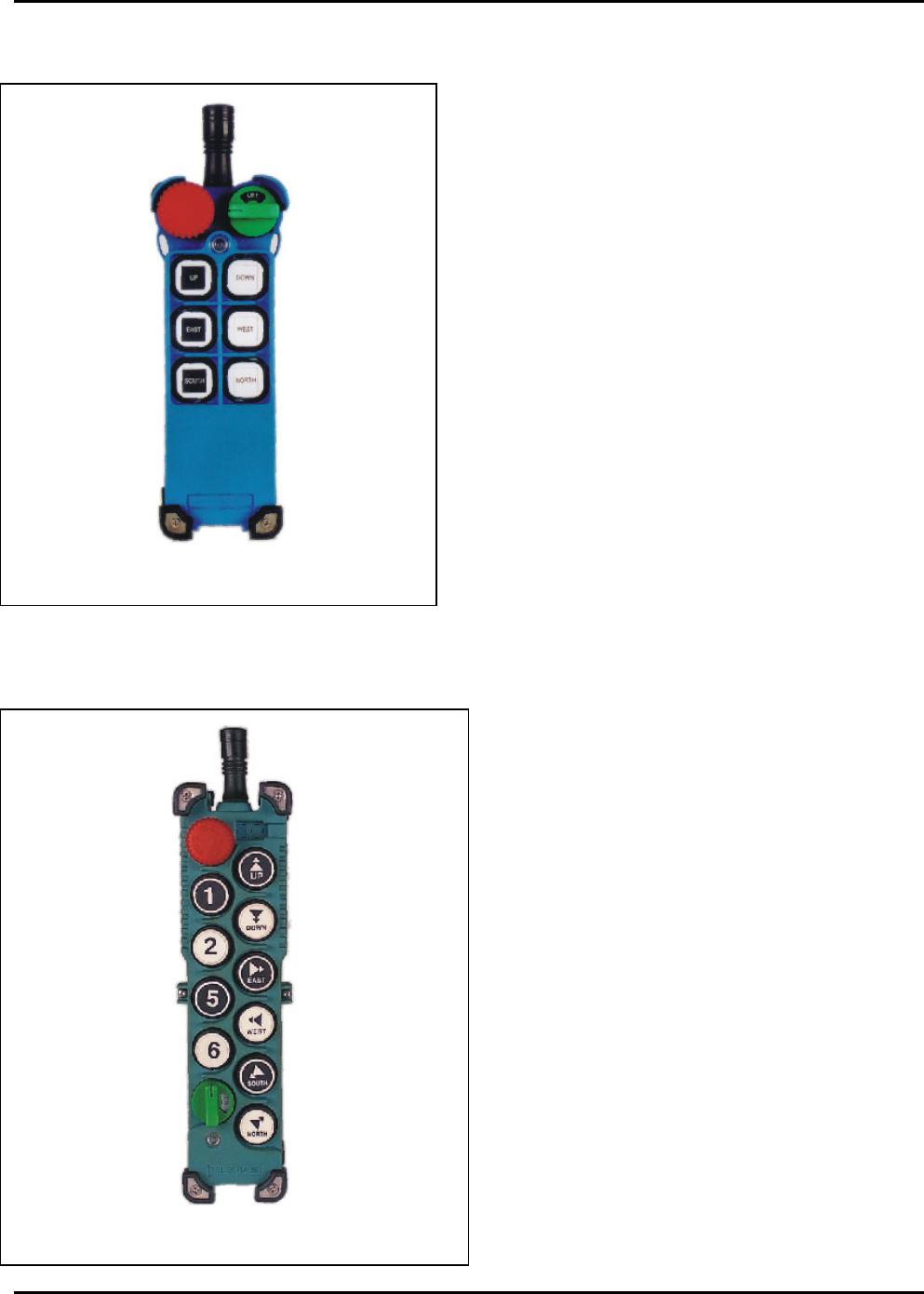
3.3 N1-Style Transmitter
The following models are available in the N1-
Style:
• F22-2S1
• F22-2D1
• F22-4S1
• F22-4D1
• F22-6S1
• F22-6D1
• F22-10S1
• F22-10D1
Figure 3 is a picture of the F22-10S1, an N1-
Style transmitter.
Figure 2: F22-6D Transmitter
Figure 3: F22-10S1 Transmitter
Intercontinental Technologies, Ltd.
Chapter 3 Page 7 of 87
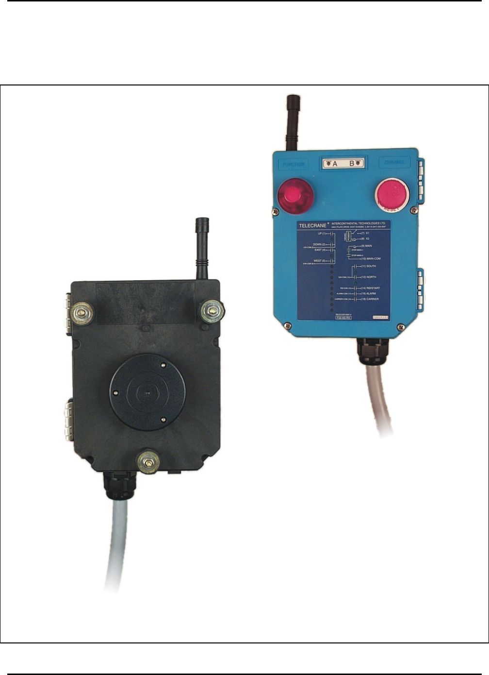
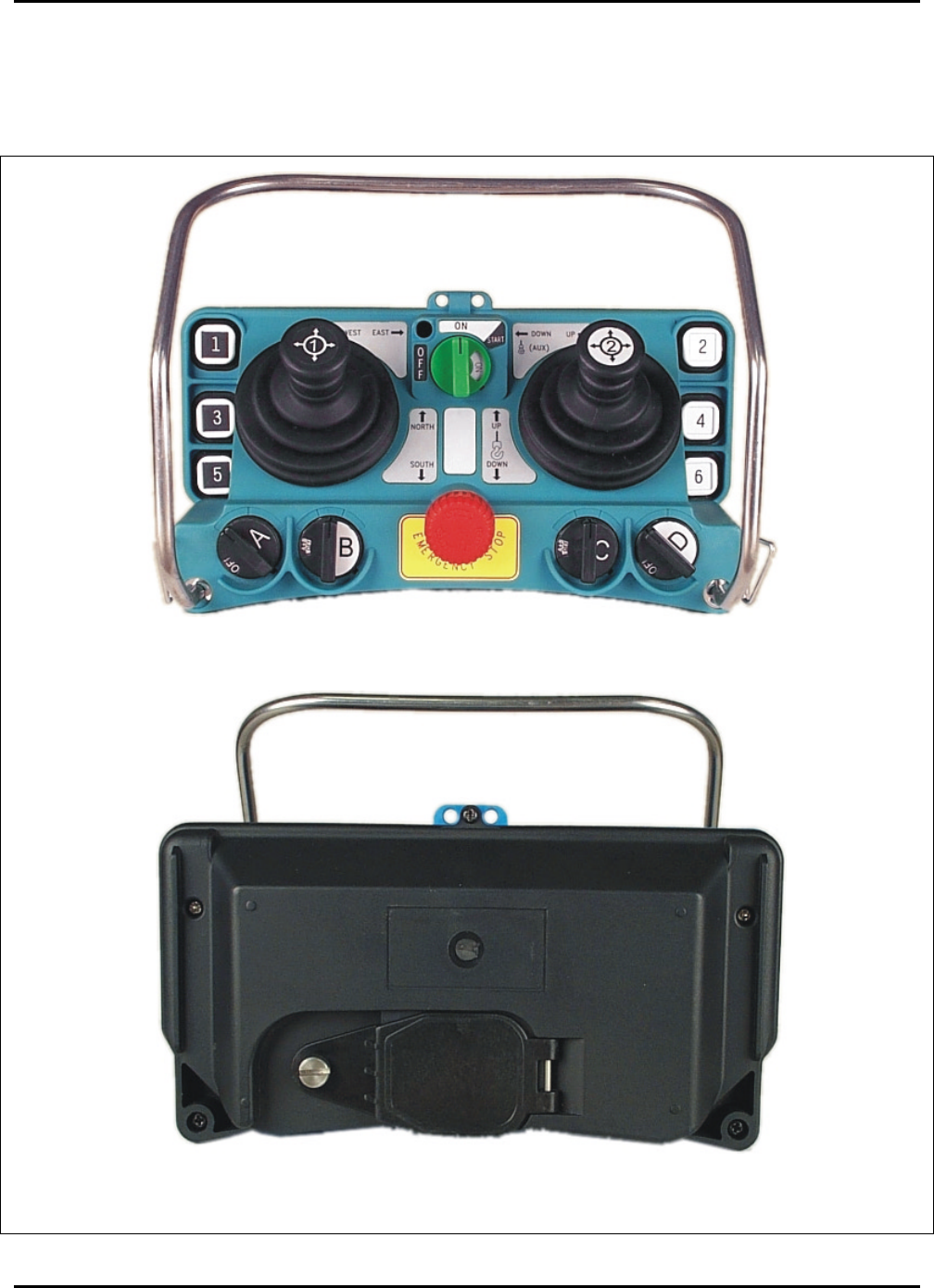
3.4 Typical Receiver for Handheld Models
Figure 4 below shows the front and back of a typical receiver for handheld models.
Figure 4: Typical Receiver for Handheld Models (front and back)
Intercontinental Technologies, Ltd.
Page 8 of 87 Chapter 3
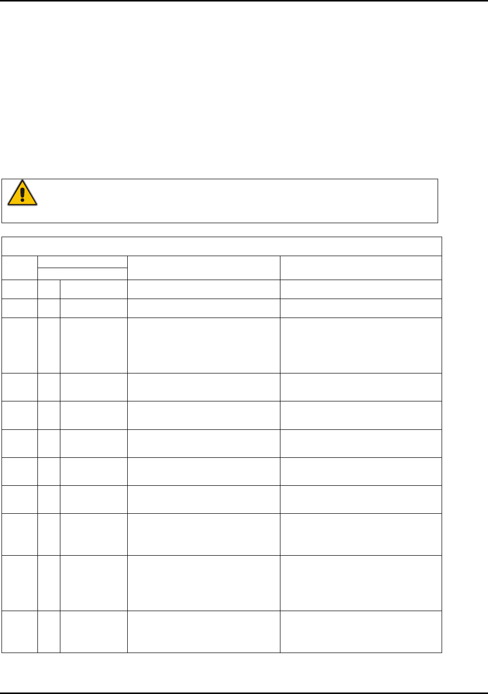
3.5 Transmitter for the Model F22-J Joystick Controller
Figure 5 below shows the top and bottom of the F22-J joystick transmitter.
Figure 5: F22-J Joystick Transmitter (top and bottom)
Intercontinental Technologies, Ltd.
Chapter 3 Page 9 of 87
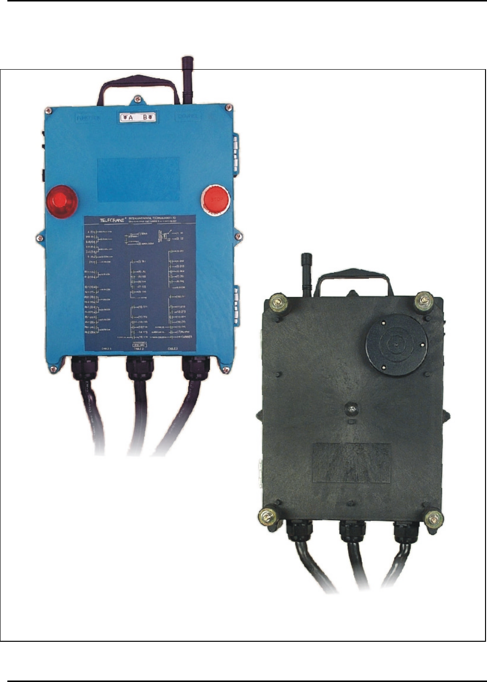
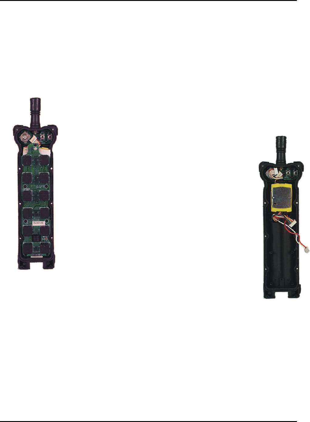
3.6 Receiver for the Model F22-J Joystick Controller
Figure 6 below shows the front and back of the receiver for the F22-J joystick controller.
Figure 6: F22-J Receiver (front and back)

Intercontinental Technologies, Ltd.
Page 10 of 87 Chapter 3
THIS PAGE INTENTIONALLY LEFT BLANK
Intercontinental Technologies, Ltd.
Chapter 4 Page 11 of 87
Chapter 4 Operation of the F22 Series Industrial Radio Remote
Controller
Note: Operating industrial equipment can be hazardous.
Use TELECRANE equipment only in accordance with the
directions specified in this manual and follow all safety
guidelines. Only trained personnel should use TELECRANE
equipment.
4.1 Normal Operation of the Handheld and Joystick Models
The F22 Series Industrial Radio Remote Controls offer flexibility for a variety of applications and
functions that can be specified and set at the factory. The system consists of a receiver and two
transmitters, and uses a series of pushbuttons and other controls to operate a crane or industrial
equipment. This chapter describes the general operation of the TELECRANE system, and provides
specific information related to both the handheld and joystick models.
4.1.1 Pre-Operational Checks
Before you operate this product, perform the following checks to ensure that the unit is in proper
working order:
Periodically inspect the limit switches on the crane and ensure that they actuate correctly and stop
the motion they control.
Inspect the position and location of the equipment to ensure that the transmitter and receiver are not
exposed to a damaging environment such as high temperatures or high impact.
4.1.2 Power-On Procedure
Inspect the transmitter and receiver at the start of each work
day to ensure safe operation of this product.
Note: If the password feature has been enabled, follow the Power-On procedure described in Section
4.2.1. (Password feature available only on handheld models).
To turn on the transmitter:
1. Retrieve the green Rotary Key and place it in the transmitter.
2. Disable the Emergency Stop by turning the red EMS button clockwise until it pops out, then
releasing.
3. Turn the green Rotary Key Switch clockwise past “ON” to the “START” position, note the LED
color, then release. The switch will spring back to the ON position and a tone will sound. The
transmitter is now active.
Intercontinental Technologies, Ltd.
Page 12 of 87 Chapter 4
At the start of each shift, perform the following
safety checks:
1. Confirm that there is sufficient battery power
to operate the transmitter: If the LED color
during the power-on procedure was green, then
there is sufficient battery power to operate the
transmitter. If the LED color was yellow or
red, then battery power is low and all four
batteries should be replaced immediately. See
Table 4-1-3 below for more details.
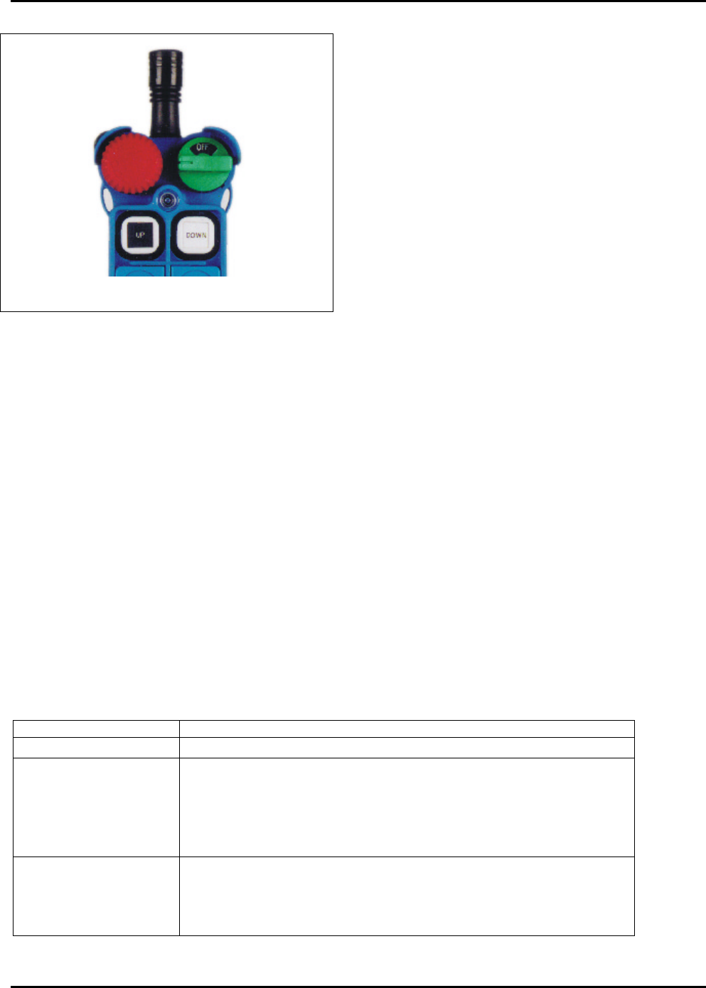
2. Test the emergency stop function by pressing
the red EMS button (shown in Figure 7). A
tone will sound and the LED will flash red and
green alternately to indicate actuation of the
emergency stop. If this does not occur, do not
use the transmitter. If the emergency stop function works correctly, then restart the transmitter.
3. Confirm that the movement of the crane or other equipment corresponds to the appropriate
control being activated on the transmitter.
4.1.3 Checking Battery Power
The transmitter will not work properly unless sufficient battery power is available. Before each use,
check the battery power and, if needed, replace the batteries following the battery changing
procedure in Section 5.3 (handheld models) or 5.4 (joystick model).
Remaining battery power is indicated by the color of the transmitter’s LED display (the circular light
adjacent to the green Rotary Key Switch). When the unit is turned on and whenever any button is
pressed, the LED will turn green, yellow, or red to indicate the remaining power.
To avoid motion of the crane or other equipment, use the Rotary Key Switch during a manual
battery check. To do this, turn the green Rotary Key Switch clockwise past “ON” to the “START”
position and hold it there. The LED will indicate the remaining power according to Table 4-1-3
below (Note: Ensure that the R0 Relay is not connected to any device because this step will activate
that relay):
Table 4-1-3 Battery Power Indicator
LED Color Battery Power Level
Green Sufficient power to operate.
Yellow Battery power is too low. Change the batteries as soon as it is
safe to do so. A warning beep will sound every 4 seconds when
any button is depressed. Follow the battery changing procedure
in Chapter 1, Section 5.3 (handheld models) or 5.4 (joystick
model).
Red There is insufficient power to operate normally and the
transmitter will send an emergency stop signal to the receiver.
Follow the battery changing procedure in Chapter 1, Section 5.3
(handheld models) or 5.4 (joystick model).
Figure 7: EMS Button and Start Key
EMS
Button
Start
Key

Intercontinental Technologies, Ltd.
Chapter 4 Page 13 of 87
4.1.4 Pushbutton Operation
The F22 Series transmitters can control a large number of motions and include factory programming
customized to your application. As a result, the specific function of each button will vary depending
on the application. See Chapter 10 of this manual for descriptions of the standard and custom button
functions that are available.
Operate the transmitter by pressing the appropriate motion and auxiliary buttons for your
application. Depending on which model you select, some or all of the following types of
pushbuttons are available:
Table 4-1-4. Pushbutton Types and Descriptions
Pushbutton Type Description
Normal
(Non-Interlocked)
Non-interlocked pushbuttons are standard ON/OFF pushbuttons.
The relay is ON when the pushbutton is pressed and held, and
OFF when the pushbutton is released. A typical application for a
non-interlocked button would be a horn.
Normal
(Interlocked)
Interlocked pushbuttons are pairs of buttons programmed to
prevent simultaneous operation of certain relays. A typical
example of interlocked pushbuttons would be to prevent
simultaneous operation of relays that actuate EAST and WEST
motions of a trolley. If two interlocked pushbuttons are pressed
at the same time, then both relays are switched OFF.
Toggle The relay is switched ON when the button is pressed once and
released. The relay is switched OFF when the same button is
pressed again and released. A typical application for a toggle
button would be lights.
On-Off A set of two buttons where one latches the relay ON and the
other latches the relay OFF. A typical application for on-off
buttons would be a magnet.
2-Step A 2-step button has two ON positions: Half- and fully-depressed.
A typical application for a 2-step button is to control a 2-speed
motion; the half-depressed position could correspond to a slow
speed and the fully-depressed position could correspond to a
faster speed. They can also control variable speed drives as well,
such as “infinitely variable” type applications.
4.1.5 Power-Down Procedures
To turn off the transmitter:
1. Press the red Emergency Stop (EMS) button.
2. Rotate the green Rotary Key Switch counterclockwise to the OFF position.
3. Remove the key and store it in a secure place.
4. If the transmitter will not be used for two weeks or longer, then remove the batteries and store
them in a cool, dry place.

Intercontinental Technologies, Ltd.
Page 14 of 87 Chapter 4
4.2 Special Functions of Handheld Models
4.2.1 Entering a Password (Optional)
The F22 Series Handheld models provide the ability to require a four-character password before use.
This feature helps prevent unauthorized or inadvertent use of industrial equipment. This feature
must be enabled, and the password set, at the factory.
If this option has been enabled, then the operator will be required to enter a four-character password
before operating the transmitter. To enter a password, follow the steps below during normal power-
on (Note: Do not follow the steps listed in Section 4.1.2):
1. Rotate the red EMS Button clockwise 45° and pull out.
2. Turn the green Rotary Key Switch clockwise to the ON position (Note: Do not turn the switch
all the way to START).
3. While the LED is flashing green, press the pushbuttons sequentially to enter the four-character
password (Note: There is a 10-second time limit).
4. If the password was entered correctly, then the buzzer will sound one long tone.
5. After the buzzer stops, turn the Rotary Key Switch to the START position and release. It will
spring back to the ON position. The transmitter is now ready for normal use.
6. If the password was entered incorrectly, then the buzzer will sound two short and one long tone.
7. After the buzzer stops, re-enter the correct password.
Table 4-2-1. Signals for Correct / Incorrect Password
Correct Password Transmitter Sounds 1 Long Tone, LED Lights Green
Incorrect Password Transmitter Sounds 2 Short and 1 Long Tone. Try again.
Note: The password must be re-entered to return to normal operation if either:
1. The EMS Button is pressed; OR
2. An emergency stop signal is sent to the receiver due to a (factory-settable) period of inactivity
(see Sections 10.4 and 10.5 for a description of the Auto-Shutdown feature).
4.2.2 Ratcheting Operation
Ratcheting is the ability to increase or decrease speed in discrete steps. This function is available on
handheld models F22-10D1, F22-12D, F22-6D and F22-6D1. The “ratchet up” button is 5 on
F22-10D1 and F22-12D, and South on F22-6D and F22-6D1. The “ratchet down” button is 6 on
F22-10D1 and F22-12D, and North on F22-6D and F22-6D1. To use ratcheting:
1. Press and hold the button controlling the desired motion, then press the “ratchet up”
pushbutton to incrementally increase the speed of the equipment, or the “ratchet down”
pushbutton to incrementally decrease the speed of the equipment.
2. When a motion button is fully depressed, one touch of the “ratchet up” button will move to the
next highest speed. Repeated touches will increase the speed up to four more times (six total
speeds, including the initial 2-step button press).

Intercontinental Technologies, Ltd.
Chapter 4 Page 15 of 87
3. To reduce the speed, press the “ratchet down” button once. Repeated pressing will reduce the
speed to the lowest speed of the ratcheting feature. To get to the lowest speed, lift the motion
button from the second step to the first step.
Note: When accelerating or decelerating with the ratchet function, the motion button must be fully
depressed. If the motion button is fully released, then the speed will return to zero. If a two-step
motion button is partially released, then the speed will return to the lowest setting.
Table 4-2-2 Pushbuttons for Ratcheting
Any Motion Button/Second Speed + Pushbutton 5 or South Increase Speed
Any Motion Button/Second Speed + Pushbutton 6 or North Decrease Speed
4.2.3 Inching Operation
Inching is the ability to move a load in small increments so that it can be more precisely controlled,
without requiring the user to press and release buttons very rapidly. This function is available on all
handheld models with pushbutton 5. To use the inching function:
1. Ensure that all pushbuttons are released and that the equipment is motionless.
2. Press and hold the 5 pushbutton.
3. Press the applicable motion pushbutton to move the load a small distance in that direction.
4.3 Special Functions of Joystick Models
The Model F22-J Joystick Type Remote Controller offers broad flexibility on a variety of
applications through user-specific, customizable functions that are pre-programmed at the factory.
The system includes a transmitter and a spare transmitter, each with two joysticks, six pushbuttons,
and four rotary dials. The F22-J controller transmitter offers the most flexibility for a wide range of
applications.
4.3.1 Buttons on the Joystick Controller
The Joystick controller includes pushbuttons similar to those on the F22 Series Handheld units. The
pushbuttons can control motion or auxiliary functions and are custom-programmed at the factory for
your specific application. See Chapter 10 for detailed descriptions of the functions that are
available, and Section 10.2 for a discussion of button types.
4.3.2 Joystick Operation: Direction of Movement
The F22-J includes two joysticks, each of which can control four primary directions of motion. The
directions of motion can be combined so that, for example, a bridge/trolley combination can move
North and East simultaneously. The functions for axial movements of Joystick 1 and Joystick 2 are
preset at the factory based on your application. A typical setting might be:

Intercontinental Technologies, Ltd.
Page 16 of 87 Chapter 4
Joystick 1
(Controls Bridge and Trolley)
Joystick 2
(Controls Hoists)
Direction Motion Direction Motion
Forward Bridge moves North Forward Hoist moves UP
Back Bridge moves South Back Hoist moves DOWN
Left Trolley moves West Left Aux Hoist moves DOWN
Right Trolley moves East Right Aux Hoist moves UP
4.3.3 Joystick Operation: Speed Settings
In each of the four directions of motion, the joysticks can have up to five detent positions. For
example, there could be five detents in the forward direction, each of which could be associated to a
speed setting. A smaller number of detent positions can also be specified and set at the factory.
The time elapsed between a change from one speed to the next can be customized for your particular
application.
4.3.4 Joystick Operation: Rotary Switch Operation
The F22-J joystick type transmitter is supplied with four rotary switches labeled A, B, C, and D.
Rotary switches A and D are simple ON/OFF switches designed to control items like magnets and
lights.
The B and C switches are three-position switches normally used to switch between different
systems. For example, rotary switch B could control Hoist 1, Hoist 2, or both Hoist 1 and Hoist 2
simultaneously.
The table below summarizes the available switches and switch positions:
Switch A Switch B* Switch C* Switch D
Available
Positions
On
Off
A
(A+B) or Neither
B
A
(A+B) or Neither
B
On
Off
*Three-position switch
Note that the names of Switches A and B are not related in any way to the names of Positions A and
B.

Intercontinental Technologies, Ltd.
Chapter 5 Page 17 of 87
Chapter 5 User Maintenance
5.1 Safety Aspects of User Maintenance
• In general, maintenance on this product should only be performed by your installer, distributor,
or ITL.
• Ensure that anyone performing maintenance on the unit is thoroughly familiar with its operation.
• The crane’s power sources should be shut off before any maintenance begins, unless absolutely
required for troubleshooting the unit. When the power to the crane is on, use extreme caution.
High voltage or unexpected movement of the crane can cause death or severe injury.
• Fall prevention devices should be used when anyone is working on the crane at an elevated
height.
• Only ITL-certified maintenance personnel should attempt a repair more involved than the
swapping of printed circuit boards. Improper repair can compromise the built-in safety features
and can cause unexpected operation and damage.
• This product uses four AA alkaline batteries. When replacing batteries, all four must be replaced
at the same time.
• ITL does not recommend use of nickel-cadmium batteries due to voltage characteristics that
cause a sudden loss of power when discharged. They also have less capacity than AA alkaline
batteries.
5.2 Unusual Alarms
The F22 Series Industrial Radio Remote Controller is equipped with a self-diagnostic program. If a
malfunction is detected during the operation of the equipment, the system will sound an alarm on
the receiver to indicate a receiver malfunction, or a buzzer on the transmitter to indicate a transmitter
malfunction. If this occurs, review Chapter 6 of the Operator’s Manual, “Basic Troubleshooting.”
5.3 Battery Changing Procedure (Handheld Models)
1. Unscrew the cover of the battery compartment.
2. Remove and discard the old batteries.
3. Install 4 new AA alkaline batteries into the battery compartment, noting the polarity markings.
4. Replace the cover of the battery compartment.
5. Confirm proper installation: If the batteries were installed correctly, the transmitter will beep
twice. If the transmitter does not beep twice, check battery polarity.
5.4 Battery Changing Procedure (Joystick Models)
1. Unscrew and open the hinged battery cover.
2. Remove the battery caddy and discard the old batteries.
3. Install 4 new AA alkaline batteries into the battery caddy noting the polarity markings.
4. Replace the battery caddy and close the hinged battery cover.
5. Confirm proper installation: If the batteries were installed correctly, the transmitter will beep
twice. If the transmitter does not beep twice, check battery polarity.

Intercontinental Technologies, Ltd.
Page 18 of 87 Chapter 5
THIS PAGE INTENTIONALLY LEFT BLANK

Intercontinental Technologies, Ltd.
Chapter 6 Page 19 of 87
Chapter 6 Basic Troubleshooting
6.1 Reliability
The F22 Series of remote controllers are designed for high reliability in an industrial environment.
Design features include:
• Heavy duty, shock-resistant design
• Constructed from corrosion-resistant materials
• Button life in excess of 2,000,000 cycles
• Self-diagnostics to simplify troubleshooting and maintenance
In addition to these features, all handheld and joystick models are delivered with two complete
transmitters. This provides the ultimate in reliability; in the event that one transmitter is damaged,
you can switch to the backup transmitter.
6.2 Self-Diagnostics and Error Codes
Both the transmitter and receiver of the F22 Series are designed with sophisticated self-diagnostics
to simplify troubleshooting and maintenance. This allows for detection of malfunctions in the
pushbuttons, joystick, RF circuit, and relay driver circuits. The system will sound an alarm signal in
Morse Code if a malfunction occurs in either the transmitter or receiver (see Chapter 11 for a table of
error codes).
If an error message is detected by the self-diagnostic program, then the appropriate alarm signal will
sound and a Power-Off of the system will be initiated. Until the malfunction is corrected, the system
will remain shut down (see Section 7.1 for more information).
6.3 User Troubleshooting
In the event that a problem occurs, follow the listed steps in order until the unit is functioning
normally. If you are unable to solve the problem, then return the unit to your distributor for service.
1. Check the EMS switch. If it is depressed, reset it by rotating clockwise until it pops up.
2. Check the green Rotary Start Switch. If it is missing, replace it. If it is present, turn it to OFF.
Then turn it clockwise past “ON” to the “START” position, then release. The switch will spring
back to the ON position and a tone should sound.
3. Ensure that the batteries are present and charged (see Section 4.1.3) and replace if necessary.
4. Turn off the transmitter and try using the backup transmitter. (Note: Before using the backup
transmitter, check its battery power (see Section 4.1.3) and replace batteries if necessary). If use
of the backup transmitter solves the problem, return the malfunctioning transmitter to your
distributor for service. If the backup transmitter does not work, then the problem may be with
the receiver.
If the transmitter is damaged or malfunctioning, then return it to your distributor for service and use
the backup transmitter in the meantime.

Intercontinental Technologies, Ltd.
Page 20 of 87 Chapter 6
If the receiver appears to be damaged or malfunctioning, then ensure that the green carrier light
illuminates when a button on a working transmitter is pressed. This light is one of the LED’s on the
front cover of the receiver. If the carrier light does not illuminate, contact your distributor.
Both the transmitter and receiver are equipped with self-diagnostics. If either one detects a
malfunction, it will sound an error message in Morse code. If this occurs, record the error message
(a series of long and short tones) and inform your distributor.
Intercontinental Technologies, Ltd.
Chapter 7 Page 21 of 87
Part 2: Technician’s Manual
Chapter 7 Safe Installation
Emergency Procedure
In case of emergency, perform these steps IN ORDER:
1. Press the Red STOP Button.
2. Turn the Green Rotary Key Switch to the OFF position and remove the key from
the transmitter.
3. Switch off the main power to the crane.
4. Contact your distributor or installer.
NOTE: Read ALL safety information before you install or operate
this product.
7.1 Emergency Procedures
If the F22 unit detects an error or system fault, it will issue an emergency STOP command and
deactivate all systems programmed for a STOP command. It is therefore important to install the F22
system correctly so that if it detects a fault, it can perform an emergency stop and the crane will shut
down safely.
7.2 General Safety Information
In an industrial environment, safety must always be a top priority. Persons responsible for
installation, operation, and maintenance must make certain that both their actions and the equipment
on which they work are safe. This chapter includes a list of safety rules that must be followed when
working with TELECRANE products, as well as cranes in general. This list is not intended to be all-
inclusive. General industrial safety rules must always be followed. If there is any doubt about how to
proceed, always take the safest course of action.
7.3 Installation Safety
• Before installing or operating this product, read this manual thoroughly. If you have any
questions, please contact ITL.
• Only qualified personnel who are familiar with the product and who have read these safety
instructions should install TELECRANE products.
• All sources of power to the crane or controlled equipment must be de-energized and applicable
lockout/tag out procedures executed before installing the unit.
• Before installing the receiver, energize it in a controlled environment (for example, an office)
where it can be tested and set up properly before it is mounted in the field.

Intercontinental Technologies, Ltd.
Page 22 of 87 Chapter 7
• Before installation, be certain to understand the electrical functioning of the crane, including the
order and relationship of motions and contactors.
• Fall prevention devices should be used when anyone is working on the crane.
• The receiver must be securely attached and located where it will not be hit by any moving part of
the building, crane, or load.
• The crane must be equipped with limit switches for each motion and a main power contactor that
cuts off all power to the motors of the crane when it is de-energized.
• Special care must be taken for magnets and other load-carrying devices; ensure that if the crane
is de-energized the load remains supported.
• The receiver must be located so that it receives sufficient signal strength from the transmitter.
The preferred location is in sight of the operator. However, if this is not possible (e.g., if the
receiver unit is in a metal box), then an external antenna should be mounted such that it is in
sight of the operator.
• Test the unit before placing it in service. If the crane does not work exactly as intended, fix the
problem and test it again.

Intercontinental Technologies, Ltd.
Chapter 8 Page 23 of 87
Chapter 8 Installation
8.1 Transmitter Installation
No special installation is required for F22 Series Industrial Radio Remote Controller transmitters.
However, before the unit can be operated, check the battery power (see Section 4.1.3). If fresh
batteries are required, install them as described below:
8.1.1 Battery Installation (Handheld Models Only)
1. Unscrew the cover of the battery compartment.
2. If present, remove and discard the old batteries.
3. Install 4 new AA alkaline batteries into the battery compartment, noting the polarity markings.
4. Replace the cover of the battery compartment.
5. Confirm proper installation: If the batteries were installed correctly, the transmitter will beep
twice. If the transmitter does not beep twice, check battery polarity.
8.1.2 Battery Installation (Joystick Models Only)
1. Unscrew and open the hinged battery cover.
2. If present, remove the battery caddy and discard the old batteries.
3. Install 4 new AA alkaline batteries into the battery caddy noting the polarity markings.
4. Replace the battery caddy and close the hinged battery cover.
5. Confirm proper installation: If the batteries were installed correctly, the transmitter will beep
twice. If the transmitter does not beep twice, check battery polarity.
8.2 Receiver Installation
Precautions During Receiver Installation
1. Observe all safety precautions and use fall protection devices when climbing the
crane.
2. Turn off the main power source to the crane before installation to prevent
electrical shock.
3. Securely fasten the receiver to the crane and ensure that it is located such that it
does not touch any part of the building during operation.
4. Inspect the crane’s limit switches and other applicable safety devices before
installation to ensure that they are in proper working condition.
5. Understand the crane power and control circuits and the function settings of the
remote controller before installation.
6. Locate the receiver away from motors, frequency converters, and power cables
to avoid radio interference.
7. Use an extended antenna if the receiver is installed in a metal enclosure.
8.2.1 Preparing for Receiver Installation
1. Select a proper location.
• Select a stable place.

Intercontinental Technologies, Ltd.
Page 24 of 87 Chapter 8
• If possible, select a place where you can see the receiver or antenna during operation.
• Select a place away from motors, relays, high-voltage wiring, magnetic switches, and power
cables.
• The receiver must be at least 3 cm away from any obstacles.
2. Determine the available power source. The standard input voltage for the handheld’s receiver is
120 VAC, 60 Hz (240 VAC and 12 or 24 V, AC or DC, are also available). The joystick’s
receiver auto-detects the power source and can accept either 120 VAC, 60 Hz or 240 VAC, 60
Hz, with no action required by the installer.
8.2.2 Mounting and Connecting the Receiver
To mount and connect the receiver, perform the following steps:
1. Turn off the main power of the crane.
2. Drill the holes for the mounting screws, install the receiver, and then mount the receiver using
6mm nuts on the vibration-resistant rubber stand-offs. Refer to the Technical Sheet for the
receiver for the size and location of the mounting holes.
3. Connect the wires from the cable to the control circuit of the crane. Refer to the Technical
Sheets in Chapter 14 for a schematic diagram of the receiver (or see the schematic on the front of
the receiver itself). Note that the numbers in parentheses on the schematic correspond to the
wire number in the cable.
4. Secure the cables to avoid wear due to the vibration of the crane or other factors.
5. Twist and pull out the red Stop button on the receiver.
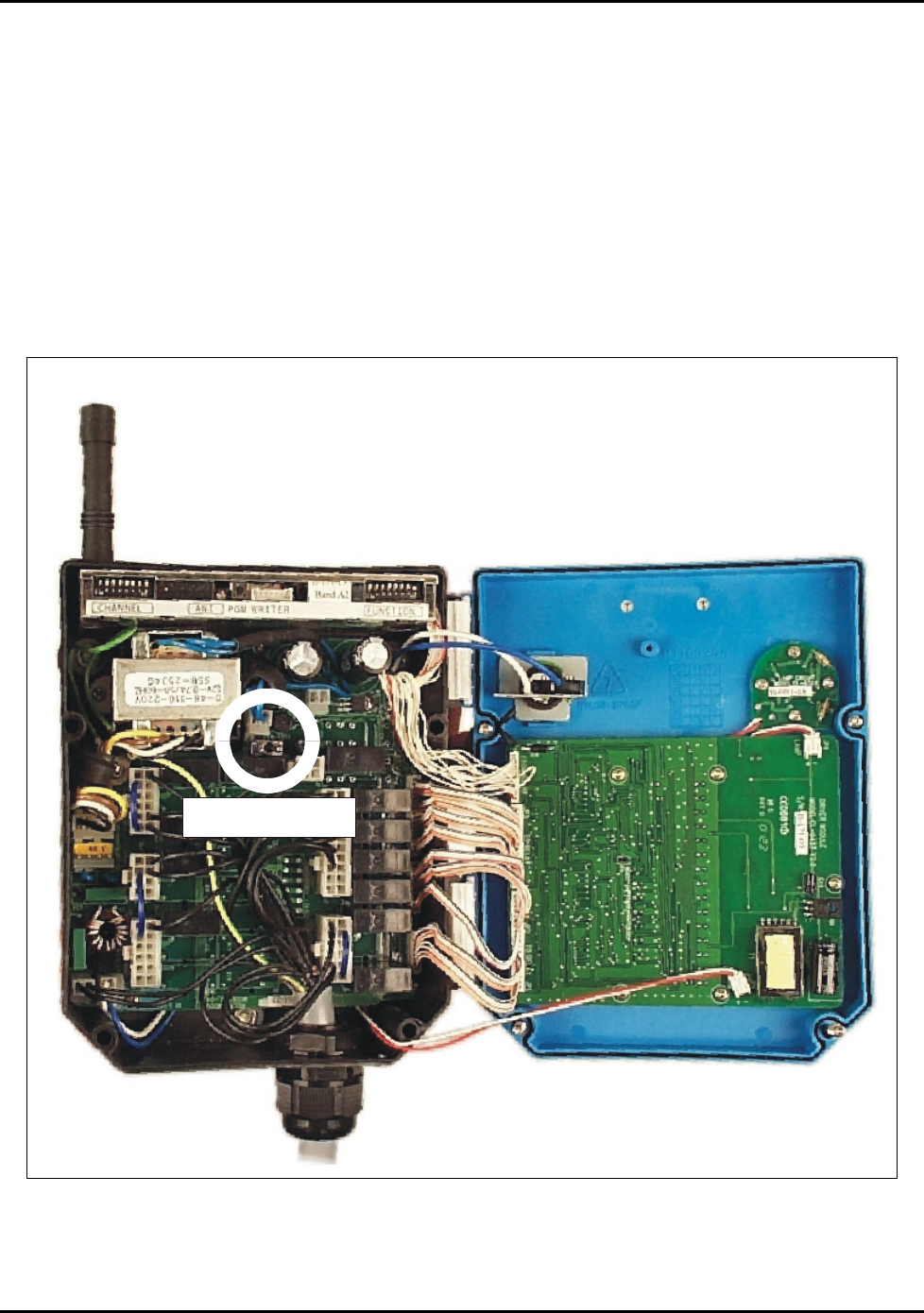
8.2.3 Receiver Installation Test Plan
The Run/Test toggle switch inside the receiver is provided to enable testing of the unit before it is
placed in service. When the switch is in the RUN position, the unit functions normally. When the
switch is in the TEST position, relay power is interrupted; the LEDs will light but the relays will not
actuate.
To test the unit:
1. Open the top cover of the receiver and set the Run/Test switch to the TEST position (see Section
12.2.5).
2. Turn on the main power for crane.
3. Using the transmitter, test each button and function; the relays will not actuate but the LEDs will
illuminate.
4. After testing, set the Run/Test switch to the RUN position and replace the top cover of the
receiver.
8.3 Installation of Optional Accessories
For installation of any optional accessories such as the Extended Antenna Kit, refer to the
accessory’s Technical Sheet in Chapter 14.

Intercontinental Technologies, Ltd.
Chapter 9 Page 25 of 87
Chapter 9 Programming By Computer
9.1 Overview
The Telecrane F22 Series Radio Remote Controls use a Windows based application program to read,
write, and change their programming. This programming is generally performed at the factory when
a unit is ordered, and is selected by the customer from the options in Chapter 10 and communicated
by means of the “Programming Sheets” in Chapter 14. In some specific cases, for example, when a
large distributor wishes to stock a number of units, for which the programming requirements are not
known when the units are ordered from ITL, this programming must be accomplished outside the
factory. ITL can provide to such a distributor a laptop computer, preloaded with the application
program and other required programs. Instructions for use of the computer and program are
provided with the unit.

Intercontinental Technologies, Ltd.
Page 26 of 87 Chapter 9
THIS PAGE INTENTIONALLY LEFT BLANK

Intercontinental Technologies, Ltd.
Chapter 10 Page 27 of 87
Chapter 10 Function Settings
Industrial Radio Remote Controllers are used in diverse operating environments and have a wide
range of applications and uses. This creates a need for flexibility and control over the setting of the
functions designed into these controllers. Default parameters are set at the factory, but many
functions and parameters can be customized to provide particular operating functions.
This Chapter provides a detailed list of the available functions of the F22 Series and the range of
settings for each. The Technical Sheets in Chapter 14 also include a summary list of parameters and
settings that can be customized to meet your specific needs.
Please note that the F22 Series includes many customizable functions that are set at the factory and
not usually changed. To avoid confusion, only those functions that are typically specified by the
user are listed here. However, if you have a need for a function setting that is not listed, please
contact ITL to determine if that function is available.
10.1 Description
Many of the functions of the F22 Series are set at the factory to meet most user’s requirements, and,
in most cases, no change is required. However, if you have a need that requires changes from the
default setting, your unit can be specially programmed at the factory. The tables below list the
transmitter and receiver functions, default settings, and custom settings available on the F22 Series
Handheld and F22-J Joystick Model Industrial Radio Remote Controllers. Please contact ITL or
your local distributor for more information regarding alternate function settings, or refer to the
Technical Sheets in Chapter 14 of this Manual.
10.2 F22 Series Handheld Transmitter Function Settings
The table below shows the functions available on the handheld F22 Series models, their available
settings, and their default settings. Note: This table lists all functions for the F22 Handheld models
depending on which buttons are available on each specific model number. Refer to the Technical
Sheets in Chapter 14 for a list of functions available by model.
Table 10.2: Handheld Transmitter Functions and Default Settings
Function/Setting Description /Notes Available Settings Default Setting
Enable
Password
Enable or disable the
Password Function
• Enabled
• Disabled
Disabled
Password Password to be entered by
user before operation
• 4 character
password
N/A
UP Button Control button • Normal,
interlocked
• Normal, not
interlocked
• Toggle (on/off)
• On (off is button
DOWN)
Normal,
interlocked with
button DOWN

Intercontinental Technologies, Ltd.
Page 28 of 87 Chapter 10
Function/Setting Description /Notes Available Settings Default Setting
DOWN Button Control button • Normal,
interlocked
• Normal, not
interlocked
• Toggle (on/off)
• Off (on is button
UP)
Normal,
interlocked with
button UP
EAST Button Control button • Normal,
interlocked
• Normal, not
interlocked
• Toggle (on/off)
• On (off is button
WEST)
Normal,
interlocked with
button WEST
WEST Button Control button • Normal,
interlocked
• Normal, not
interlocked
• Toggle (on/off)
• Off (on is button
EAST)
Normal,
interlocked with
button EAST
SOUTH
Button
Control button • Normal,
interlocked
• Normal, not
interlocked
• Toggle (on/off)
• On (off is button
NORTH)
Normal,
interlocked with
button NORTH
NORTH
Button
Control button • Normal,
interlocked
• Normal, not
interlocked
• Toggle (on/off)
• Off (on is button
SOUTH)
Normal,
interlocked with
button SOUTH
1 Button Control button • Normal, not
interlocked
• Normal,
interlocked with
button 2
• Toggle (on/off)
• On (off is button 2)
Normal, not
interlocked

Intercontinental Technologies, Ltd.
Chapter 10 Page 29 of 87
Function/Setting Description /Notes Available Settings Default Setting
2 Button Control button • Normal, not
interlocked
• Normal,
interlocked with
button 1
• Toggle (on/off)
• Off (on is button 1)
Normal, not
interlocked
3 Button Control button • Normal, not
interlocked
• Normal,
interlocked with
button 4
• Toggle (on/off)
• On (off is button 4)
Normal, not
interlocked
4 Button Control button • Normal, not
interlocked
• Normal,
interlocked with
button 3
• Toggle (on/off)
• Off (on is button 3)
Normal, not
interlocked
5 Button Control button • Normal, not
interlocked
• Toggle (on/off)
• Ratchet up
• Inching:
o 0.1 seconds
o 0.2 seconds
o 0.3 seconds
o 0.4 seconds
o 0.5 seconds
• Normal, not
interlocked
• No inching
6 Button Control button • Normal, not
interlocked
• Toggle (on/off)
• Ratchet down
Normal, not
interlocked

Intercontinental Technologies, Ltd.
Page 30 of 87 Chapter 10
10.3 F22 Series Joystick Transmitter Function Settings
The table below shows the functions available on the F22-J (Joystick) model, the available settings,
and the default settings.
Table 10.3 Joystick Transmitter Functions and Default Settings
Function/Setting
Description /Notes Available Settings Default Setting
1 Button Control button • Normal, not
interlocked
• Normal, interlocked
with button 2
• Toggle (on/off)
• On (off is button 2)
• Specific, for dual
motor systems
Normal, interlocked
with button 2
2 Button Control button • Normal, not
interlocked
• Normal, interlocked
with button 1
• Toggle (on/off)
• Off (on is button 1)
• Specific, for dual
motor systems
Normal, interlocked
with button 1
3 Button Control button • Normal, not
interlocked
• Normal, interlocked
with button 4
• Toggle (on/off)
• On (off is button 4)
Normal, interlocked
with button 4
4 Button Control button • Normal, not
interlocked
• Normal, interlocked
with button 3
• Toggle (on/off)
• Off (on is button 3)
Normal, interlocked
with button 3
5 Button Control button • Normal, not
interlocked
• Normal, interlocked
with button 6
• Toggle (on/off)
• On (off is button 6)
Normal, interlocked
with button 6

Intercontinental Technologies, Ltd.
Chapter 10 Page 31 of 87
Function/Setting
Description /Notes Available Settings Default Setting
6 Button Control button • Normal, not
interlocked
• Normal, interlocked
with button 5
• Toggle (on/off)
• Off (on is button 5)
Normal, interlocked
with button 5
A Dial Control Dial On/off On/off
B Dial Control Dial • A, A+B, B
• A, Off, B
A, A+B, B
C Dial Control Dial • A, A+B, B
• A, Off, B
A, A+B, B
D Dial Control Dial On/off On/off
Joystick 1 2-axis (X and Y) joystick
controller
• 4 directions, 5 or
fewer detents* in
each direction,
interlocking
• Extensive custom
programming
available, see
Technical Sheet in
Chapter 14
4 directions, 5 detents
in each direction
Joystick 2 2-axis (X and Y) joystick
controller
• 4 directions, 5 or
fewer detents* in
each direction,
interlocking
• Extensive custom
programming
available, see
Technical Sheet in
Chapter 14
4 directions, 5 detents
in each direction
*Refer to Chapter 14 for additional detent settings
10.4 F22 Handheld Series Receiver Function Settings
The table below shows the functions available on the F22 Handheld Series receivers, their available
settings, and their default settings. Note: This table lists all functions for the F22 Series receivers;
certain models may not have all listed functions.

Intercontinental Technologies, Ltd.
Page 32 of 87 Chapter 10
Table 10.4 Handheld Receiver Functions and Default Settings
Function/Setting
Description /Notes
Available Settings
Default Setting
Auto-
Shutdown
Time
Elapsed idle time before
receiver automatically shuts
itself down
• Never
• 10 minutes
• 20 minutes
• 30 minutes
• 1 hour
• 2 hours
• 3 hours
• 4 hours
1 hour
Acceleration
Delay
Time between actuation of
relays when button is fully
depressed
• 0 seconds
• 0.3 seconds
• 1 second
• 1.5 seconds
• 2 seconds
• 3 seconds
• 4 seconds
0 seconds
Second
Function of
Start Position
Turning key to START after
already started.
• Sound alarm
• Close R0
momentary
• Close R0 toggle
Sound Alarm
10.5 F22-J Receiver Function Settings
The table below shows the functions available on the F22-J (Joystick) Receiver, the available
settings, and the default settings.
Table 10.5 Joystick Receiver Functions and Default Settings
Function/Setting
Description /Notes
Available Settings
Default Setting
Auto-
Shutdown
Time
Elapsed idle time before
receiver is automatically shut
down
• Never
• 10 minutes
• 20 minutes
• 30 minutes
• 1 hour
• 2 hours
• 3 hours
• 4 hours
1 hour

Intercontinental Technologies, Ltd.
Chapter 10 Page 33 of 87
Function/Setting
Description /Notes
Available Settings
Default Setting
Joystick 1
X-axis
Acceleration
Delay
Joystick 1
Y-axis
Acceleration
Delay
Joystick 2
X-axis
Acceleration
Delay
Joystick 1
Y-axis
Acceleration
Delay
Time between actuation of
relays when joystick is
moved
• 0 seconds
• 0.3 seconds
• 0.5 seconds
• 0.8 seconds
• 1 second
• 1.3 seconds
• 1.6 seconds
• 1.8 seconds
• 2.1 seconds
• 2.4 seconds
• 2.6 seconds
• 2.9 second
• 3.1 seconds
• 3.4 seconds
• 3.7 seconds
• 3.9 seconds
0.5 seconds
Acceleration
Delay for
Buttons 1 to 6
Relays
Time between actuation of
relays when button is fully
depressed
• 0 seconds
• 0.3 seconds
• 0.5 seconds
• 0.8 seconds
• 1 second
• 2 seconds
• 2.1 seconds
• 2.4 seconds
• 2.6 seconds
• 2.9 seconds
• 3 seconds
• 3.1 seconds
• 3.4 seconds
• 3.7 seconds
• 3.9 seconds
• 5 seconds
0 seconds
Second
Function of
Start Position
Turning key to START after
already started
• Sound alarm
• Close R0
momentary
• Close R0 toggle
Sound alarm

Intercontinental Technologies, Ltd.
Page 34 of 87 Chapter 10
THIS PAGE INTENTIONALLY LEFT BLANK
Intercontinental Technologies, Ltd.
Chapter 11 Page 35 of 87
Chapter 11 Alarm Codes
This Chapter provides a listing of Alarm Codes to be used during diagnostics and repair activities.
Please refer to Chapter 6 for troubleshooting information.
1. If the F22 detects an error, an alarm tone may sound. The alarm tones are given in Morse code,
where “.” (dot) indicates a short alarm for a duration of 0.26 second and “—” (dash) a long
alarm for a duration of 0.78 second. The interval between each alarm tone is 0.26 second.
2. If the unit’s self-diagnostics detect an error and sound the alarm tones, then the unit will be
disabled and will not function until the malfunction is corrected.
Maintenance technicians can use these error codes for troubleshooting,
however the best solution is usually replacement of the defective module.
Table 11.1: Alarm Codes for Transmitters
Error Message Item
Alarm Code
Description Possible Correction
1 E
.
Low Battery (warning) Replace batteries.
2 R
. - .
Batteries excessively low Replace batteries.
3 F
. . - .
Pushbutton Malfunction
(shorted)
1. Release all pushbuttons and
start key when inserting
batteries.
2. Replace the encoder module
4 X
- . . -
Joystick 1 Forward and
Backward Malfunction
Replace Joystick 1.
5 K
- . -
Joystick 1 Left and Right
Malfunction
Replace Joystick 1.
6 Y
- . - -
Joystick 2 Forward and
Backward Malfunction
Replace Joystick 2.
7 1
. - - - -
Joystick 2 Left and Right
Malfunction
Replace Joystick 2.
8 S
. . .
RF Module Malfunction 1. Ensure antenna is tight.
2. Replace RF module.
9 C
- . - .
EEPROM in handheld
transmitter is faulty.
1. Replace the encoder module
2. Reprogram function settings
(see Chapter 9).
10 D
- . .
EEPROM in the encoder
does not have function
settings set or the settings are
incomplete (handheld only).
Reprogram function settings
(see Chapter 9).
11 H
. . . .
EEPROM in joystick
transmitter is faulty.
1. Replace the encoder module
2. Reprogram function settings
(see Chapter 9).

Intercontinental Technologies, Ltd.
Page 36 of 87 Chapter 11
Table 11.2: Alarm Codes for Receivers
Error Message Item
Alarm Code
Description Possible Correction
1 A
. -
UP Relay Coil bad
(Hand-held)
Joystick 2 Relay Coil bad 2 B
- . . .
U/D 2S Relay Coil bad
(Hand-held)
3 C
- . - .
DOWN Relay Coil bad
(Hand-held)
4 D
- . .
EAST Relay Coil bad
(Hand-held)
R1~R6 Relay Coil bad
(Joystick)
5 E
.
E/W 2S Relay Coil bad
(Hand-held)
Joystick 1 Relay Coil bad 6 F
. . - .
WEST Relay Coil bad
(Hand-held)
7 G
- - .
SOUTH Relay Coil bad
(Hand-held)
8 H
. . . .
S/N Relay Coil bad
(Hand-held)
9 I
. .
NORTH Relay Coil bad
(Hand-held)
10 J
. - - -
R1 Relay Coil bad
(Hand-held)
11 K
- . -
R1/R2 2S Relay Coil bad
(Hand-held)
12 L
. - . .
R2 Relay Coil bad
(Hand-held)
13 M
- -
R3 Relay Coil bad
(Hand-held)
14 N
- .
R3/R4 Relay Coil bad
(Hand-held)
15 O
- - -
R4 Relay Coil bad
(Hand-held)
16 Q
- - . -
MAIN Relay Coil bad
(Hand-held)
Replace the relay module.

Intercontinental Technologies, Ltd.
Chapter 11 Page 37 of 87
Table 11.2: Alarm Codes for Receivers
Error Message Item
Alarm Code
Description Possible Correction
17 R
. - .
The voltage input exceeds
tolerance.
1. Disconnect the cable from
the receiver.
2. Turn off the main power to
the crane and check the
power-input voltage.
3.Check to see that the voltage
select plug is at the correct
position. (handhelds only)
4. Inspect and make sure the
power is normal before
resuming operation.
18 S
. . .
RF Circuit malfunction 1. Ensure antenna is tight.
2. Replace the receiver/
decoder module.
19 Y
- . - -
Interference by the same
model of Remote Controller
1.Install a less sensitive
antenna.
2.Change to a new frequency.
(Contact ITL or your dealer).
20 1
. - - - -
Interference by another radio
signal on the same frequency
1. If the interference is not
serious or is short term,
start the Remote Controller
when the interference is
over.
2. If the interference is serious,
change to a new frequency.
(Contact ITL or your
dealer).
21 Z
- - . .
EEPROM in the
receiver/decoder does not
have function settings set or
are incomplete.
Reprogram function settings
(see Chapter 9).

Intercontinental Technologies, Ltd.
Page 38 of 87 Chapter 11
THIS PAGE INTENTIONALLY LEFT BLANK
Intercontinental Technologies, Ltd.
Chapter 12 Page 39 of 87
Chapter 12 Principles of Operation of Major Subcomponents
This Chapter provides an overview of the major functions of the F22 Series, including a description
of the transmitter, the receiver, and the major parts of each.
12.1 Transmitter
The most important components of the transmitter are the Encoder/Button printed circuit board, the
RF Module, and an EEPROM.
12.1.1 Encoder/Button PCB
This module is the heart of the transmitter. It contains the pushbuttons, power
control circuitry, micro-controller, and EEPROM (see Figure 8). The micro-
controller encodes the information from the pushbuttons, along
with security code and error correction data, into a serial data
stream. This data stream, after passing through an audio-
frequency-shift-keying circuit, is sent to the transmitter RF
module.
12.1.2 Transmitter RF Module
This module is a narrowband FM transmitter with a digitally
synthesized frequency output using a phase locked loop circuit
(see Figure 9).
12.1.3 EEPROM
This component, found on both the Encoder/Button PCB and
Receiver/Decoder Module, contains all of the programming and
security code information used by the micro-controller. It is a
non-volatile memory device, meaning that it does not require
constant supply of power to hold its contents.
Figure 8: Encoder/Button PCB
Figure 9:
Transmitter RF
Module
Intercontinental Technologies, Ltd.
Page 40 of 87 Chapter 12
12.2 Receiver
The most important components of the receiver are the Receiver/Decoder Module, the Relay printed
circuit board, the LED printed circuit board, the EEPROM, the Mainline Indicator printed circuit
board, and the Run/Test Switch.
12.2.1 Receiver/Decoder Module
This module combines a narrowband FM receiver, the frequency of which is digitally synthesized,
with a decoder circuit, which converts the audio signal from the receiver to a serial data stream of
relay commands. It contains a micro-controller, which examines the incoming signal and
determines, by means of
the security code and
other information,
whether it contains valid
commands to change the
state of the relays. It then
issues these commands to
the Relay PCB.
12.2.2 Relay PCB
This module latches the
serial relay command
data and drives the output
relays. It also contains
the power supply for the
rest of the receiver.
12.2.3 LED PCB
This module displays the
state of all of the
receiver’s relays by
means of green LEDs
(see Figure 10).
Figure 10: LED Printed Circuit Board on Joystick Receiver
Intercontinental Technologies, Ltd.
Chapter 12 Page 41 of 87
12.2.4 Mainline Indicator Lamp PCB
This module indicates, by means of several bright red LEDs, when the mainline relay is activated
and the unit is ready to operate.
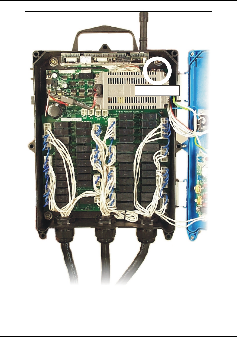
12.2.5 Run/Test Switch
This switch, part of the Relay PCB, interrupts the flow of power to the operating coils of the relays,
thus rendering them inoperative. The LED PCB is unaffected by this switch, and can be used to test
the equipment without movement of the crane. The switch functions in the same manner for both
the handheld and joystick models (see Figures 11 and 12).
Run/Test Switch
Figure 11: Location of Run/Test Switch in Receiver for Handhelds
Intercontinental Technologies, Ltd.
Page 42 of 87 Chapter 12
Run/Test Switch
Figure 12: Location of Run/Test Switch in Receiver for Joystick

Intercontinental Technologies, Ltd.
Chapter 13 Page 43 of 87
Chapter 13 Customer-Specific Information
13.1 Serial Numbers and Security Codes
An F22 System typically includes one receiver and two transmitters, however, it is possible to
include more components such as additional transmitters or receivers. Each component has a unique
serial number, composed of two parts separated by a dash. The security code (system serial number)
is the first part, and the component serial number is the second part. Serial numbers are used to track
individual components for repair and warranty purposes. Security codes are used to track system-
wide parameters such as frequency and programming information.
When you purchase a system, record the serial and system numbers below for later reference:
List of Serial Numbers Here
13.2 Function Settings
The F22 Series of Industrial Radio Remote Controllers are customizable to meet the specific needs
of each user. Chapter 10 of this Manual provides a detailed list of the available functions and
settings, and the Technical Sheets in Chapter 14 provide a summary list.
When you purchase a system, record the custom settings below for later reference:
List of Function Settings Here

Intercontinental Technologies, Ltd.
Page 44 of 87 Chapter 13
THIS PAGE INTENTIONALLY LEFT BLANK

Intercontinental Technologies, Ltd.
Chapter 14 Page 45 of 87
Chapter 14 Product Technical Sheets
This Chapter contains tables of transmitters, receivers, accessories, and Technical Sheets for each
system model.
14.1 F22 Series Systems
The table below lists all F22 Systems by feature and application. Technical Sheets for each system
are provided later in this Chapter.
Table 14-1. Available Models by Feature and Applications
System Model
No.
Transmitter
Type
Buttons General Application
F22-2S Mini Up/Down Hoist or Winch, Single-Speed
F22-4S Mini Up/Down, East/West Monorail, Single-Speed
F22-6S Mini Up/Down, East/West,
North/South
3-Motion Crane, Single-Speed
F22-12S Mini Up/Down, East/West,
North/South, 1, 2, 3, 4, 5, 6
6-Motion Crane, Single-Speed or
A, B, A+B type applications
F22-2S1 N1 Up/Down Hoist or Winch, Single-Speed
F22-4S1 N1 Up/Down, East/West Monorail, Single-Speed
F22-6S1 N1 Up/Down, East/West,
North/South
3-Motion Crane, Single-Speed
F22-10S1 N1 Up/Down, East/West,
North/South, 1, 2, 5, 6
5-Motion Crane, Single-Speed or
A, B, A+B type applications
F22-2D Mini Up/Down Hoist, Two-Speed
F22-4D Mini Up/Down, East/West Monorail, Two-Speed
F22-6D Mini Up/Down, East/West,
North/South
3-Motion Crane, Two-Speed
F22-12D Mini Up/Down, East/West,
North/South, 1, 2, 3, 4, 5, 6
6-Motion Crane, Two-Speed or
A, B, A+B type applications
F22-2D1 N1 Up/Down Hoist, Two-Speed
F22-4D1 N1 Up/Down, East/West Monorail,Two-Speed
F22-6D1 N1 Up/Down, East/West,
North/South
3-Motion Crane, Two-Speed
F22-10D1 N1 Up/Down, East/West,
North/South, 1, 2, 5, 6
5-Motion Crane, Two-Speed or
A, B, A+B type applications
F22-J Joystick
(Belly-Box)
(includes 2
transmitters)
2 independent joysticks, 4
dial switches, 6 pushbutton
switches
Extensive applications, refer to
Technical Sheets.

Intercontinental Technologies, Ltd.
Page 46 of 87 Chapter 14
14.2 F22 Transmitter and Receiver Part Numbers
The table below lists the correct transmitter and receiver part numbers for each system model
number:
Table 14-2: Available F22 Transmitters and Receivers
System
Model No.
Transmitter
Part No.
Receiver
Part No.
F22-2S F22-2S-TX
F22-2S1 F22-2S1-TX
F22-4S F22-4S-TX
F22-4S1 F22-4S1-TX
F22-6S F22-6S-TX
F22-6S1 F22-6S1-TX
F22-6S-RX
F22-10S1 F22-10S1-TX
F22-12S F22-12S-TX F22-12S-RX
F22-2D F22-2D-TX
F22-2D1 F22-2D1-TX
F22-4D F22-4D-TX
F22-4D1 F22-4D1-TX
F22-6D F22-6D-TX
F22-6D1 F22-6D1-TX
F22-6D-RX
F22-10D1 F22-10D1-TX
F22-12D F22-12D-TX F22-12D-RX
F22-J F22-J-TX F22-J-RX
14.3 F22 Series: Accessories
The table below provides a summary of available optional accessories used to enhance the function
and operation of the F22 Series.
Table 14-3: Available Optional Accessories
Model Application Feature
24 Volt
Converter
This optional accessory allows the
unit to be used with 24 volt input
power, instead of the standard
110/220 volts.
Permits the unit to be used in 24 volt
applications.
Extended
Antenna
Kit
This optional accessory allows the
standard antennas to be extended to
a more suitable position to the
operator. This can be used when the
location for mounting the receiver
could cause a problem with the
signal coming from the transmitter,
such as being mounted in a box on
the crane
This provides flexibility in where the
Receiver can be installed within a work
environment. See Section 14.4 for details.

Intercontinental Technologies, Ltd.
Chapter 14 Page 47 of 87
14.4 Extended Antenna Kit
The table below lists the part numbers for Extended Antenna Kits based on system model numbers:
Table 14-4: Extended Antenna Kit Part Numbers
Extended
Antenna
Kit Part No.
Description Used on Models
24B0102 Extended antenna kit with 2 foot coax cable and
antenna.
All Handheld
models
24B0103 Extended antenna kit with 3 foot coax cable and
antenna.
All Handheld
models
24B0104 Extended antenna kit with 4 foot coax cable and
antenna.
All Handheld
models
24B0105 Extended antenna kit with 5 foot coax cable and
antenna.
All Handheld
models
24B0106 Extended antenna kit with 6 foot coax cable and
antenna.
All Handheld
models
24B0110 Extended antenna kit with 10 foot coax cable and
antenna.
All Handheld
models
24B0120 Extended antenna kit with 20 foot coax cable and
antenna.
All Handheld
models
24B0100 Extended antenna kit with custom length of coax
cable and antenna.
All Handheld
models
24B0204 Extended antenna kit with 4 foot coax cable and
antenna F22-J
24B0220 Extended antenna kit with 20 foot coax cable and
antenna. F22-J
24B0200 Extended antenna kit with custom length of coax
cable and antenna. F22-J