Intercontinental Technologies F24-142 Industrial Radio Remote Control Transmitter User Manual F21 2 and 4 Manual
Intercontinental Technologies Ltd Industrial Radio Remote Control Transmitter F21 2 and 4 Manual
User Manual
Intercontinental Technologies Ltd. 558 Plate Drive Bldg. #2, East Dundee, IL 60118
Ph: 847-426-9597, Fax: 847-426-9724, TELECRANE.COM
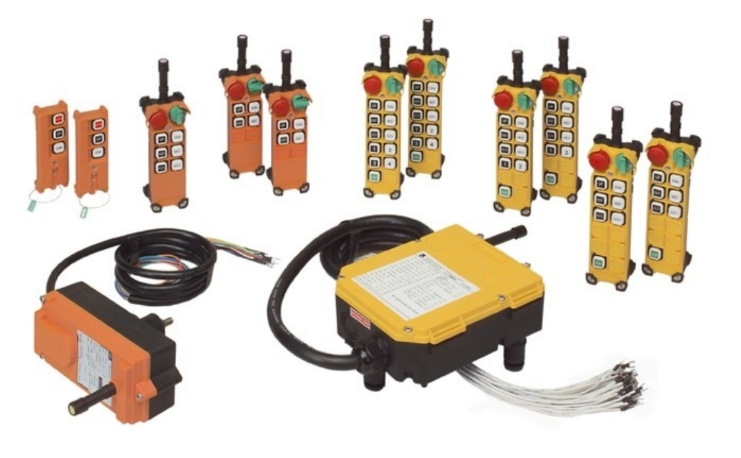
Telecrane Radio Remote Control
F21 Series & F24 Series
Manual
Rev. 4a
April 18, 2012

1
Telecrane F21 Series & F24 Series Manual
Chapter Index
Page
General Specifications 3
1.0 Installation Instructions 5
2.0 Operation Instructions 6
3.0 Safety 8
4.0 Troubleshooting on Installation 10
5.0 Programming 11
6.0 Internal Horn Option 13
7.0 Product Selection Guide 14
8.0 Product Options 16
9.0 F21 Receiver and Wiring Diagrams 17
10.0 F24 Receiver and Wiring Diagrams 18
Program and Button Labeling 19
This manual Copyright 2006, 2009, 2011 Intercontinental Technologies, Ltd.
2
This Page Intentionally Left Blank

3
Technical Specifications for: F21-2S, 2D, 4S, 4D, 6S and F24-6S, 6D, 8S, 8D, 10S, 10D, 12S, 12D
Receiver input voltage: 110 volts AC.
Other Input voltages available 220 VAC, 12V AC/DC, 24 VAC/DC
Temperature: -35 deg C to 75 deg C (-31 deg F to 167 deg F)
Receiver relay ratings: the receiver relays are rated at 10 amps at 250 volts AC. All COM
wires are fused at 10A in both the F21 and F24 series. The total current drawn through the
receiver relays (through the COM wire) must not exceed 10A.
Transmitter weights: 5 ounces for F21-2S, 2D; 9 ounces for F21-4S, 4D, 6S; 11 ounces for
F24-6S, 6D, 8S, 8D, 10S, 10D
Transmitter dimensions: F21-2S, 2D are 5.2” x 1.75” x .9”; F21-4S, 4D, 6S are 6.2” x 2.4”x2”;
F24-6S, 6D, 8S, 8D, 10S, 10D, 12S, 12D are 7.25” x 2.4” x 2”
Frequency generation: Crystal (plug-in)
Transmitter and Receiver housing material: 30% glass fiber-reinforced nylon-6
Transmitter button life: Tested to 2,000,000 operations
Control range: 150 feet for F21-2 button models, 250 feet for F21-4 & F21-6 button models and
500+ feet for all F24 models.
Transmitter batteries: 2 AA alkaline batteries.
Channel
Frequency
Channel
Frequency
Channel
Frequency
Channel
Frequency
1
310.0325
11
312.7075
21
315.3825
31
318.0575
2
310.3000
12
312.9750
22
315.6500
32
318.3250
3
310.5675
13
313.2425
23
315.9175
33
318.5925
4
310.8350
14
313.5100
24
316.1850
34
318.8600
5
311.1025
15
313.7775
25
316.4525
35
319.1275
6
311.3700
16
314.0450
26
316.7200
36
319.3950
7
311.6375
17
314.3125
27
316.9875
37
319.6625
8
311.9050
18
314.5800
28
317.2550
38
319.9300
9
312.1725
19
314.8475
29
317.5225
10
312.4400
20
315.1150
30
317.7900
Channel
Frequency
Channel
Frequency
Channel
Frequency
Channel
Frequency
112
428.5350
123
431.4775
134
434.4200
145
437.3625
113
428.8025
124
431.7450
135
434.6875
146
437.6300
114
429.0700
125
432.0125
136
434.9550
147
437.8975
115
429.3375
126
432.2800
137
435.2225
148
438.1650
116
429.6050
127
432.5475
138
435.4900
149
438.4325
117
429.8725
128
432.8150
139
435.7575
118
430.1400
129
433.0825
140
436.0250
119
430.4075
130
433.3500
141
436.2925
120
430.6750
131
433.6175
142
436.5600
121
430.9425
132
433.8850
143
436.8275
122
431.2100
133
434.1525
144
437.0950

4
Warranty:
Intercontinental Technologies, Ltd. (ITL) guarantees that this product meets its published specifications at the time of shipment. This equipment
is warranted against defects in material and manufacturing for a period of one year from the date of shipment. During the warranty period, ITL
will repair or replace defective components at no charge, if the failure of the product was due to defective material or manufacturing. For
warranty service, the product must ultimately be returned to ITL. The buyer must pay shipping charges to the ITL service facility, and ITL will
pay return ground shipping charges. Warranty service on F21 and F24 units shall be provided by ITL only and ITL will not be responsible for
service or repair costs charged by third parties. ITL will not be liable for any damage to the warranted product, and no other warranty is
expressed or implied, except as explicitly described. ITL does not warranty any consumable parts, including batteries, fuses, buttons, relays, or
housings. This warranty does not include damage caused by improper installation (including ignoring environmental specifications), improper or
insufficient maintenance, any modifications, improper operation, or improper software interfacing. The remedies provided herein are the buyer’s
sole and exclusive remedies. ITL shall not be liable for any direct, indirect, special, incidental, or consequential damages.
FCC and Industry Canada Approval Information
The following information applies to transmitters:
This device complies with part 15 of the FCC Rules and RSS-210 of Industry Canada. Operation is subject to the
following two conditions: (1) This device may not cause harmful interference, and (2) this device must accept any
interference received, including interference that may cause undesired operation.
Changes or modifications not expressly approved by Intercontinental Technologies, Ltd. could void the user’s
authority to operate equipment.
Ce dispositif est conforme aux normes CNR-210 d’Industrie Canada et la partie 15 des règles de la FCC.
L’utilisation de ce dispositif est autorisée seulement aux conditions suivantes: 1) il ne doit pas produire de brouillage
et 2) l’utilisateur du dispositif doit être prêt à accepter tout brouillage radioelectrique reçu, même si ce brouillage est
susceptible de compromettre le fonctionnement du dispositif .
This equipment has been tested and found to comply with the limits for a Class A digital device, pursuant to Part 15
of the FCC Rules. These limits are designed to provide reasonable protection against harmful interference when the
equipment is operated in a commercial environment. This equipment generates, uses, and can radiate radio
frequency energy and, if not installed and used in accordance with the instruction manual, may cause harmful
interference to radio communications. Operation of this equipment in a residential area is likely to cause harmful
interference in which case the user will be required to correct the interference at his own expense.
The following information applies to receivers:
Models F21-2S and F21-2D, Models F21-4S and F21-4D,
Model F21-6S, Models F24-6S and F24-6D,
Models F24-8S and F24-8D, Models F24-10S and F24-10D,
Model F24-12S and F24-12D
5
1.0 Installation Instructions:
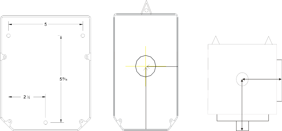
1. The F21 and F24 receivers should be mounted in a location that is convenient to the control
box and is securely attached to the equipment. The F21 receiver measures 7.37” L x 3.37” W
x 7.10” D and is mounted by drilling one 5/16” (8mm) hole and the F24 receiver measures 10”
L x 6.5” W x 4.5” D and is mounted by drilling three ¼” (6mm) holes (see diagrams below).
Mount the receiver using the supplied hardware. It is best to keep the receiver as far away
(approximately 6 feet) from variable frequency drives and the motors and cables attached to
them to avoid interference.
1.5”
3.4”
1.9”
2.2”
F24 Receiver Mounting Diagram F21 Receiver Mounting Diagram F21-2S Mini Receiver Mounting Diagram
2. The F21 receiver wires are color coded, and the F24 receiver wires are numbered. The wires are
identified on the label on the top of the receiver and on the wiring diagrams on page 15 of this
manual.
3. All the contacts in the receiver are “dry” relay contacts. This means that is there is no internal
source of power to the contacts. You will need to connect the “common” lead for each output
or set of outputs that you plan to use to the same power supply that it would be connected to in
a corded pendant. For most cranes this wire is X1 (the 120 volt AC control transformer “hot”
side). Some cranes have separate hoist/trolley and bridge transformers. In these cases,
connect each transformer’s X1 to the function(s) it powers. There is no requirement that the
common leads be connected to a 120 volt AC supply- these are “dry” relay contacts; whatever
you put into the common wire, comes out each function’s wire when that relay closes. The
only restrictions are, do not exceed 10 amps or 250 volts AC. For DC applications call the
factory at 1-800-382-3558.
4. Put 2 AA alkaline batteries into each transmitter. For F21-2 button models, remove the 4
screws on the back of the transmitter. Insert the batteries as indicated inside the unit. Replace

6
the screws. For the F21-4, F21-6, F24-6, F24-8, F24-10, and F24-12 button units, remove the
battery compartment cover on the bottom of the unit by unscrewing the thumb-screw. Insert
the batteries as indicated on the label inside the battery compartment. Replace the cover and
tighten the thumb-screw until the cover is fully seated against the transmitter body.
5. Test the system thoroughly before releasing it for use.
2.0 Operation Instructions:
2.1 Battery Indicator:
The LED on the front of the transmitter indicates the condition of the batteries. It will
flash green during operation if the battery power is sufficient, and will flash red if the battery
power is low. If the LED is flashing red, or if the operation becomes erratic, or will only
work from a short distance, replace both batteries with new AA alkaline batteries using the
procedure given in section 1.0.
2.2 Fuses
There are three fuses in the F21 series receivers and six fuses in the F24 series receivers.
On all models there is one fuse in the AC power line that operates the receiver (0.5A, 250V),
and one is in the internal 12 volt DC supply (1.5A, 250V). In the F21 receivers there is one
fuse in the COM wire. On the F24 series radios there are four fuses in the COM wires (10A,
250V). These fuses are for relay contact protection in the event of a short circuit in the
equipment being controlled by the radio. To replace a fuse, push down the fuse cover and
turn counter-clockwise ¼ turn with thumb and forefinger or a flat-blade screwdriver.
Remove the fuse from the cover and insert a new one of the same rating. Insert the fuse and
cover into the fuse holder, press down, and turn clockwise ¼ turn. For protection from fire
hazard, damage, or injury, always replace a blown fuse with one of the same rating.
2.3 Start Procedure for the F21-2S and F21-2D:
1. Put the green magnetic safety key into its slot in the front of the transmitter.
2. Use the UP and DOWN pushbuttons to control the equipment. The first time that either
button is pressed, the mainline contactor will engage. If there is no mainline contactor
provided on the equipment being controlled by the radio, the Main (red) wire does not
need to be connected to any of the equipment controls. The model F21-2D has two-step
buttons; pressing them to the first detent will activate the equipment at the slow speed,
and pressing them fully will activate the equipment at the fast speed.
3. Press the STOP button to stop movement immediately and drop out the mainline
contactor, if one is used.
4. Remove the green magnetic safety key whenever the transmitter is not in use to prevent
unintentional operation.

7
2.4 Start Procedures for the F21-4S, F21-4D, F21-6S:
1. If the red STOP knob is pushed in, turn it clockwise about 45 degrees to reset it and allow
it to pop up. This knob must be in the up position in order to operate the transmitter.
2. Put the green key into its slot in the front of the transmitter, next to the red STOP knob.
3. Turn the green key clockwise. The green key must go past the ON position detent, to the
START position. Then release it and it will spring back to the ON position.
4. Use the pushbuttons to control the equipment. The model F21-4D uses two-step
pushbuttons; pressing them to the first detent will activate the equipment at the slow
speed, and pressing them fully will activate the equipment at the fast speed.
5. Press the red STOP knob or turn the green key to OFF to stop movement immediately
and drop out the mainline contactor.
6. Turn the green key to OFF and remove it whenever the transmitter is not in use to prevent
unintentional operation.
7. The F21-4 and F21-6 models have an extra relay in the receiver, labeled R0. Turning the
green key to START after the equipment has already been started will close this relay.
This relay will not engage the first time the key is turned to START when starting up the
equipment. See section 5.3 for detailed information on this option.
2.5 Start Procedures for all F24 Models (except the F24-12S and 12D models)
1. If the red STOP knob is pushed in, turn it clockwise about 45 degrees to reset it and allow
it to pop up. This knob must be in the up position in order to operate the transmitter.
2. Put the green key into its slot in the front of the transmitter, next to the red STOP knob.
3. Turn the green key clockwise to the ON position, then press the green (START)
pushbutton. This will engage the mainline contactor, if one is used.
4. Use the pushbuttons to control the equipment. Models F24-6D, F24-8D, and F24-10D
use two-step pushbuttons; pressing them to the first detent will activate the equipment at
the slow speed, and pressing them fully will activate the equipment at the fast speed.
5. Press the red STOP knob or turn the green key to OFF to stop movement immediately
and drop out the mainline contactor.
6. Turn the green key to OFF and remove it whenever the transmitter is not in use to prevent
unintentional operation.
7. The F24-6, F24-8, and F24-10 models have an extra relay in the receiver, labeled R0.
Pushing the green start button after the equipment has already been started will close this
relay. This relay will not engage the first time the Start pushbutton is pressed when
starting up the equipment. See section 5.3 for detailed information on this option.

8
2.6 Start Procedures for the F24-12S, F24-12D:
1. If the red STOP knob is pushed in, turn it clockwise about 45 degrees to reset it and allow
it to pop up. This knob must be in the up position in order to operate the transmitter.
2. Put the green key into its slot in the front of the transmitter, next to the red STOP knob.
3. Turn the green key clockwise. The green key must go past the ON position detent, to the
START position. Then release it and it will spring back to the ON position.
4. Use the pushbuttons to control the equipment. The model F24-12D uses two-step
pushbuttons; pressing them to the first detent will activate the equipment at the slow
speed, and pressing them fully will activate the equipment at the fast speed.
5. Press the red STOP knob or turn the green key to OFF to stop movement immediately
and drop out the mainline contactor.
6. Turn the green key to OFF and remove it whenever the transmitter is not in use to prevent
unintentional operation.
7. The F24-12S and F24-12D models have an extra relay in the receiver, labeled R0.
Turning the green key to START after the equipment has already been started will close
this relay. This relay will not engage the first time the key is turned to START when
starting up the equipment. See section 5.3 for detailed information on this option.
3.0 Safety:
EMERGENCY PROCEDURE: In case of emergency, perform these steps IN ORDER.
1. Press the red STOP button.
2. Remove the green magnetic safety key on F21-2 button models only or turn the
green key to OFF on the F21-4, F21-6, F24-6, F24-8, F24-10, and F24-12 button
models.
3. Switch off the main power to the equipment.
4. Contact qualified service personnel.
This manual is intended for the user as a general reference only. Please consult your distributor
for specific installation or assistance with technical issues. In an industrial environment, safety
must always be a top priority. Persons responsible for installation, operation, and maintenance
must make certain that both their actions, and the equipment on which they work, are safe.
Following are a list of safety rules that must be followed when working with TELECRANE
products, as well as cranes and industrial equipment in general. This list is not intended to be all-
inclusive. General industrial safety rules must always be followed. If there is any doubt about
how to proceed, always take the safest course of action.
9
- Only qualified personnel who are familiar with the product and who have read
these safety instructions should install TELECRANE products.
- Before installing or operating this product, read this manual thoroughly. If you
have any questions, please contact ITL.
- All sources of power to the crane or controlled equipment must be de-energized
and locked out before installing the unit.
- Before installing the receiver, energize it in a controlled environment (such as an
office) where it can be tested and set up properly before it is mounted in the field.
If it does not work exactly as intended, fix the problem and test it again.
- Before installation, be certain to understand the electrical functioning of the crane
or equipment, including the sequence and relationship of motions and contactors.
- Fall prevention devices should be used when anyone is working at an elevated
height.
- The receiver must be securely attached and located where it will not be hit by any
moving part of the building, crane, or load.
- The crane or hoist must be equipped with limit switches for each motion and a
main power contactor that cuts off all power to the motors of the crane when it is
de-energized.
- Special care must be taken for magnets and other load-carrying devices to ensure
that if the crane is de-energized the load remains supported.
- The receiver must be located so that it receives sufficient signal strength from the
transmitter.
- Operating any piece of equipment in an industrial facility can be dangerous;
therefore, adequate training will need to be provided to operators of cranes or
other equipment that uses a TELECRANE product.
- At least once each shift, check the amount of power remaining in the transmitter
batteries. If it is low, change both batteries before beginning operation.
Operating the unit with excessively discharged batteries can be unsafe.
- The safety key should be removed from the transmitter whenever it is not in use
and should only be issued to authorized personnel.
- All TELECRANE Radio Remote Controls are tested before they leave the
factory. However, they should not be used in dangerous situations or in a manner
such that damage might result.
- Although the transmitter is very durable and weather-resistant, precautions should
always be taken to limit its exposure to weather, physical impact, and corrosives.
- After use, or if the unit will not be used for a long interval, turn off power to the
crane or equipment and remove the safety key from the transmitter.

10
- Remove the batteries from the transmitter if the transmitter will not be used for
two weeks or longer.
- Transmitters that are not in use, including spare transmitters, should be stored,
with batteries removed, and secured to prevent accidental operation.
- Before each shift, check that the limit switches function correctly and that
movement corresponds to the button being pressed on the transmitter.
- Do not use the equipment during lightning storms or high electrical interference
conditions.
- In general only authorized service facilities should perform maintenance on this
product.
- Ensure that anyone performing maintenance on the crane or equipment is
thoroughly familiar with its operation.
- Power should be shut off to the crane or equipment before any maintenance
begins, unless absolutely required for troubleshooting the unit. When the power
is on, use extreme caution. High voltage or unexpected movement could cause
death or severe injury.
- Only certified maintenance personnel should attempt a repair more involved than
the swapping of printed circuit boards. Improper repair can compromise the built-
in safety features and cause unexpected operation and damage.
- This product uses two AA alkaline batteries. When replacing batteries, both must
be replaced at the same time.
- ITL does not recommend use of nickel-cadmium or nickel-metal-hydride batteries
due to voltage characteristics that cause a sudden loss of power when discharged.
They also have less capacity than alkaline batteries and therefore will not last as
long.
4.0 Trouble Shooting Common Mistakes In Installation:
Receiver dead: Is 120 volt AC applied between X1 and X2 wires? On the F21
models these are the BLACK and BROWN wires; and on the F24 models they are
wires 1 and 2. You must provide both the hot and the neutral sides of the control
transformer secondary to power the unit.
Does the equipment have a mainline contactor: Not all equipment has a
mainline contactor. The best way to determine if your equipment has a mainline
contactor is to check whether there is a START and STOP on the corded pendant.
If the equipment does not have a mainline contactor then these wires do not have
to be connected. On the F21 models this wire is the MAIN wire and on the F24
models this is MAIN-IN (3) and MAIN-OUT (4). The MAIN wire on the F21

11
models will be hot when mainline is on; this wire has to be terminated with a wire
nut or isolated.
Relays close but there is no movement from the crane: Are the COMMON
wires hooked up properly? The receivers have “dry” contacts. Even though X1
and X2 have been applied to power the receiver, you still need to apply power to
the common side of the relay contacts in order to get power to your contactors.
On the F21 models the COM wire on the diagram is separate from the power
wires and on the F24 models each COM wire is completely isolated from the
others as well as the power wires. In most cranes, the COM wires will be
connected to the X1 supply.
If you have any problems or questions not covered above, please call ITL at 1-800-382-3558.
5.0 Programming options:
5.1 All units:
- Auto-shut-down time. An auto-shut-down feature is available on all models. If the
radio has not been used for a period of time the receiver automatically drops out the main
line contactor. The default setting is 1 hour for the F24 Series and “Never” for the F21
Series. Auto-shut-down times can be set between 0 and 4 hours. Typical selections are
available on the programming data sheets in the back of this manual.
- Pushbutton options. Each pushbutton is set by default to momentary (relay closes when
a button is pressed and opens when released), and interlocked in opposed motion pairs
(UP-DOWN, EAST-WEST, SOUTH-NORTH). When set as momentary, they can be set
as un-interlocked. They can also be set as toggle (press once to close relay, press again to
open) or as On-Off pairs (press On to close relay, press Off to open relay). When
programmed as toggle or On-Off, they will be set as controlled by Stop (opening
automatically when the STOP button is pressed). They can be specially rewired by the
factory for uncontrolled by Stop (unaffected by STOP button); please call for more
information.
5.2 Models F21-2D, F21-4D, F24-6D, F24-8D, F24-10D, and F24-12D:
- Acceleration delay. Delay between actuation of relays for the first and the second
detents of the two-step button can be programmed on the two speed models. This delay
time can be set between 0 and 4 seconds; default is 0 seconds. Typical selections are
available on the programming data sheet.

12
5.3 Models F21-4S, F21-4D, F21-6S, F24-6S, F24-6D, F24-8S, F24-8D, F24-10S, F24-10D,
F24-12S, and F24-12D:
- R0 function. On the F21 models the R0 relay operates when the green key is turned to
START after the unit is already started. On the F24 models the R0 relay operates when
the START button is pushed after the unit is already started. It is by default set to
momentary (closed when START key is turned on the F21 models or START button is
pressed on the F24 models, open when released). It can also be set to toggle (turn the
START key once to close, turn it again to open on F21 models or push the START button
once to close, then push the button again to open on the F24 models), or inching (does
not activate the R0 relay, but instead only allows pushbuttons pressed after turning the
key to remain on for a preset length of time, no matter how long the button is held). For
inching, the inch time may be set from 0.05 to 0.8 seconds in 0.1-second increments.
Typical selections are available on the programming data sheet.
5.4 Other Programming options for the F24 UP/DOWN 2 Step Buttons:
Dual Motor. When the first detent of the button is reached the first step relay turns ON,
when the button is fully depressed the second step relay turns ON and the first step relay
turns OFF. When the button is released back to the first detent, the first step relay will
turn ON until the button is released.
Dual Motor (1). Works the same as Dual Motor, with the difference being the first step
relay will not activate when returning from fully depressed to the first detent. The button
must be completely released and repressed in order to activate the first step relay again.
Combination. When 2 buttons are depressed simultaneously, it will result in a third
relay output that is set to toggle. The relays of the two buttons depressed will not engage,
instead a third relay will engage. This feature is designed to suit some special
applications such as lighting systems. Combination setting is prohibited for magnetic
devices. Combination setting is always set to controlled by stop. Uncontrolled by stop is
not available.
3 Speeds. The START button can be used to control a third speed. Once the motion
button (either up or down) is fully depressed, a third speed can be obtained by pushing
the START button.
Call Factory for more information 1-800-382-3558.

13
6.0 Internal Horn option:
This section describes the Internal Horn Option on the following model numbers:
F24-6S-HN F24-8S-HN F24-10S-HN
F24-6D-HN F24-8D-HN F24-10D-HN
F24-12S-HN F24-12D-HN
Instructions for use:
The Internal Horn Option operates automatically with usage of the TELECRANE F24 Series
Radio Remote Control in which it is installed. F24 models ending in ”-HN” contain this option.
It will sound the horn on two conditions:
- The horn will sound for approximately two (2) seconds upon initially pressing
START in order to provide a warning that the crane or other equipment is being
started;
- The horn may be sounded by pressing START at any time after startup, regardless
of whether a motion button is being pressed. The horn will sound as long as the
START button is pressed. (This may be eliminated: see Adjustments, below)
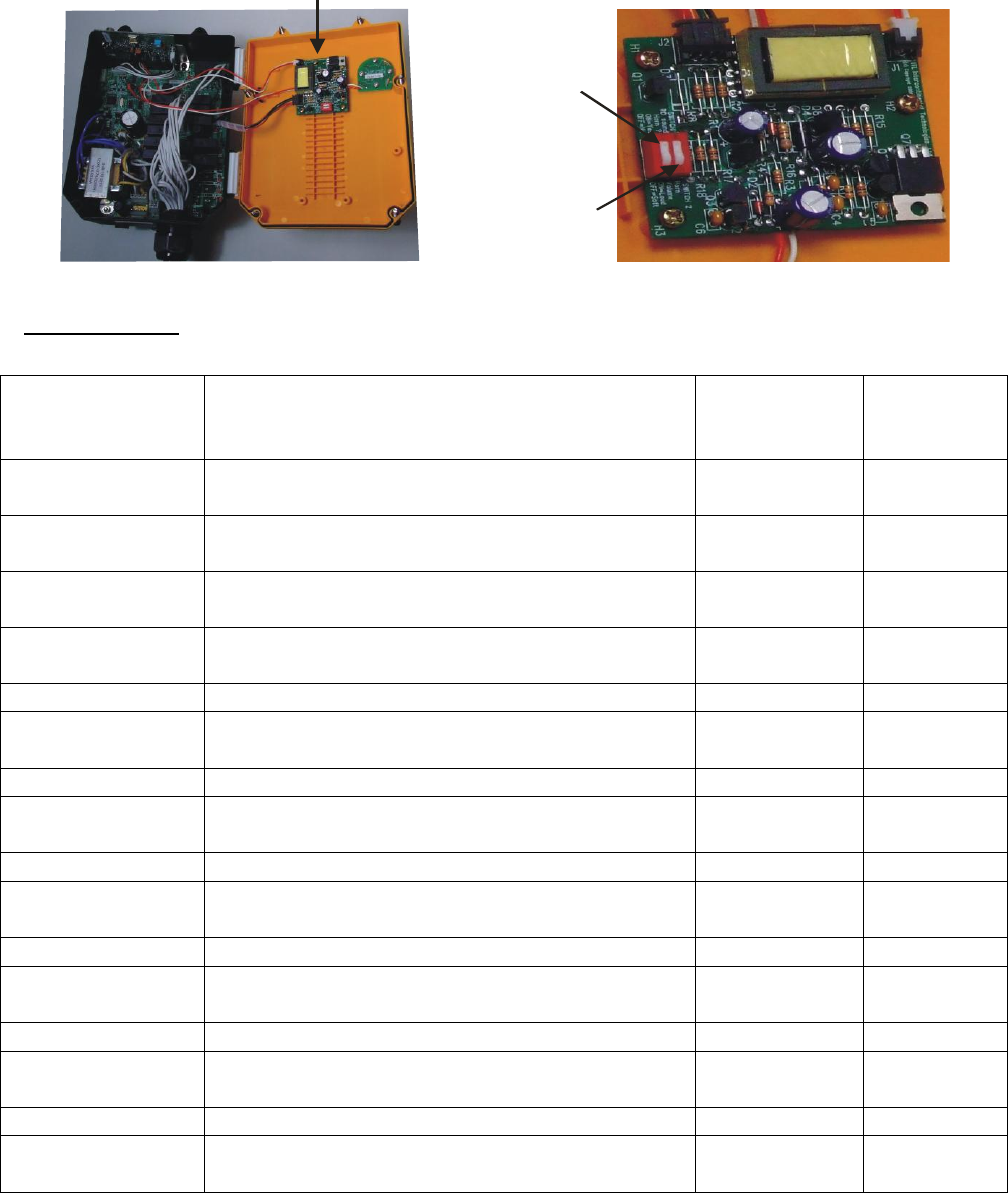
Adjustments:
There are two (2) small DIP-style rocker switches near the lower edge of the Horn printed circuit
board. This board is mounted inside the front cover of the receiver. These switches constitute
the only adjustments available on the Internal Horn Option. As shipped, both switches are set to
“ON”.
SOUNDING HORN AFTER STARTUP: The switch closer to the edge, numbered “1”,
controls whether pressing the START button after startup sounds the horn. If it is desired to use
the R0 relay without the horn sounding, press the rocker switch toward the “OFF” or “OPEN”
position. To resume sounding the horn on R0 activation, press the switch toward the “ON”
position.
14
VOLUME CONTROL: The switch toward the middle of the board, numbered “2” controls the
volume level of the horn. To reduce the volume level, press the rocker switch toward the “OFF”
or “OPEN” position. To restore full volume level, press the switch toward the “ON” position.
Horn printed circuit board
Switch
number “1”
Switch
number “2”
7.0 Product Selection Guide:
7.1 F21 Models
Complete Systems
Model
Typical Applications
Number of
Motion Buttons
& Steps
Control
Voltage
Number of
Transmitters
F21-2S
Hoist, winch, lifts, doors,
conveyors etc…
2 button, 1 step
110-220VAC
1
F21-2S-DC
Truck Equipment, winches,
hoists, etc…
2 button, 1 step
12-24 V
AC/DC
1
F21-2S-2TX
Hoist, winch, lifts, doors,
conveyors etc…
2 button, 1 step
110-220VAC
2
F21-2S-DC-2TX
Truck Equipment, winches,
hoists, etc…
2 button, 1 step
12-24 V
AC/DC
2
F21-4S
Monorails, dual hoists, etc…
4 button, 1 step
110-220VAC
1
F21-4S-DC
Truck Equipment,
monorails, dual hoists, etc…
4 button, 1 step
12-24 V
AC/DC
1
F21-4S-2TX
Monorails, dual hoists, etc…
4 button, 1 step
110-220VAC
2
F21-4S-DC-2TX
Truck Equipment,
monorails, dual hoists, etc…
4 button, 1 step
12-24 V
AC/DC
2
F21-2D
Hoist, lifts, etc…
2 button, 2 step
110-220VAC
1
F21-2D-DC
Truck Equipment, hoists,
lifts, etc…
2 button, 2 step
12-24 V
AC/DC
1
F21-2D-2TX
Hoist, lifts, etc…
2 button, 2 step
110-220VAC
2
F21-2D-DC-2TX
Truck Equipment, hoists,
lifts, etc…
2 button, 2 step
12-24 V
AC/DC
2
F21-4D
Monorails, dual hoists, etc…
4 button, 2 step
110-220VAC
1
F21-4D-DC
Truck Equipment,
monorails, dual hoists, etc…
4 button, 2 step
12-24 V
AC/DC
1
F21-4D-2TX
Monorails, dual hoists, etc…
4 button, 2 step
110-220VAC
2
F21-4D-DC-2TX
Truck Equipment,
monorails, dual hoists, etc…
4 button, 2 step
12-24 V
AC/DC
2

15
F21-6S
Overhead cranes, dual hoist
monorails, etc…
6 button, 1 step
110-220VAC
1
F21-6S-DC
Truck Equipment, dual hoist
monorails, etc…
6 button, 1 step
12-24 V
AC/DC
1
F21-6S-2TX
Overhead cranes, dual hoist
monorails, etc…
6 button, 1 step
110-220VAC
2
F21-6D-DC-2TX
Truck Equipment, dual hoist
monorails, etc…
6 button, 1 step
12-24 V
AC/DC
2
7.2 F-24 Models
The F24 Series can also be set up as 12-24 V AC/DC Control. Call factory.
F24 models ending in ”-HN” contain the internal horn option.
Complete Systems
Model
Typical Applications
Number of
Motion Buttons
& Steps
Control
Voltage
Number of
Transmitters
F24-6S
Overhead cranes, dual hoist
monorails, etc…
6 button, 1 step
110-220VAC
2
F24-6S-HN
Overhead cranes, dual hoist
monorails, etc…
6 button, 1 step
110-220VAC
2
F24-6D
Overhead cranes, dual hoist
monorails, etc…
6 button, 2 step
110-220VAC
2
F24-6D-HN
Overhead cranes, dual hoist
monorails, etc…
6 button, 2 step
110-220VAC
2
F24-8S
Overhead cranes with A, B,
A+B
8 button, 1 step
110-220VAC
2
F24-8S-HN
Overhead cranes with A, B,
A+B
8 button, 1 step
110-220VAC
2
F24-8D
Overhead cranes with A, B,
A+B
8 button, 2 step
110-220VAC
2
F24-8D-HN
Overhead cranes with A, B,
A+B
8 button, 2 step
110-220VAC
2
F24-10S
Multiple overhead cranes
and hoists
10 button, 1 step
110-220VAC
2
F24-10S-HN
Multiple overhead cranes
and hoists
10 button, 1 step
110-220VAC
2
F24-10D
Multiple overhead cranes
and hoists
10 button, 2 step
110-220VAC
2
F24-10D-HN
Multiple overhead cranes
and hoists
10 button, 2 step
110-220VAC
2
F24-12S
Multiple overhead cranes
and hoists
12 button, 1 step
110-220VAC
2
F24-12S-HN
Multiple overhead cranes
and hoists
12 button, 1 step
110-220VAC
2
F24-12D
Multiple overhead cranes
and hoists
12 button, 2 step
110-220VAC
2
F24-12D-HN
Multiple overhead cranes
and hoists
12 button, 2 step
110-220VAC
2
16
8.0 Product Options
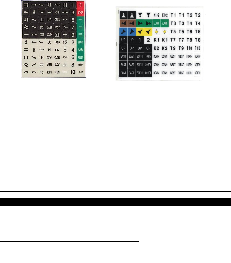
- Below are the legend sets that are available to change the button labels of the F21 and
F24 series transmitters.
Part # 22A3001 Part #22A3003
- An antenna kit is available for all F24 models effectively extending the range to 1500+
feet (line of sight). Call factory for details. 1-800-382-3558
- Cables are available as well for mounting the stock antenna outside an enclosure. Call
Factory for details. 1-800-382-3558
- F21 & F24 Spare Transmitters
Spare Transmitter
Model Numbers
Works with Models
F21-2S-TX
F21-2S
F21-2S-2TX
F21-2S-DC
F21-2S-DC-2TX
F21-4S-TX
F21-4S
F21-4S-2TX
F21-4S-DC
F21-4S-DC-2TX
F21-2D-TX
F21-2D
F21-2D-2TX
F21-2D-DC
F21-2D-DC-2TX
F21-4D-TX
F21-4D
F21-4D-2TX
F21-4D-DC
F21-4D-DC-2TX
F21-6S-TX
F21-6S
F21-6S-2TX
F21-6S-DC
F21-6S-DC-2TX
F24-6S-TX
F24-6S
F24-6S-HN
F24-6D-TX
F24-6D
F24-6D-HN
F24-8S-TX
F24-8S
F24-8S-HN
F24-8D-TX
F24-8D
F24-8D-HN
F24-10S-TX
F24-10S
F24-10S-HN
F24-10D-TX
F24-10D
F24-10D-HN
F24-12S-TX
F24-12S
F24-12S-HN
F24-12D-TX
F24-12D
F24-12D-HN
Intercontinental Technologies Ltd. 558 Plate Drive Bldg. #2, East Dundee, IL 60118
Ph: 847-426-9597, Fax: 847-426-9724, TELECRANE.COM
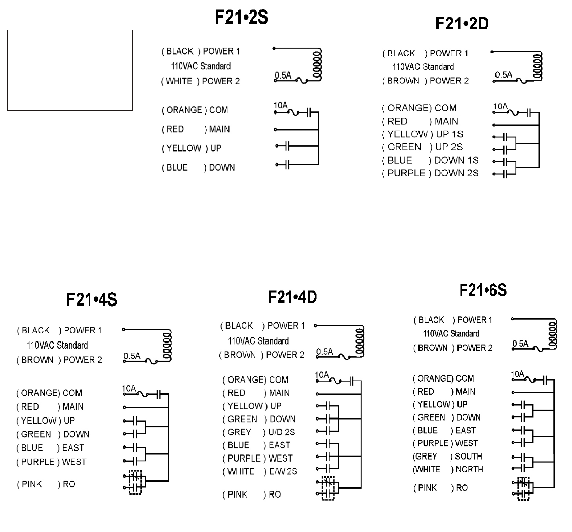
F21 Series Wiring Diagrams
F21 Series available
in 12-24VDC control
input in place of
110VAC standard.
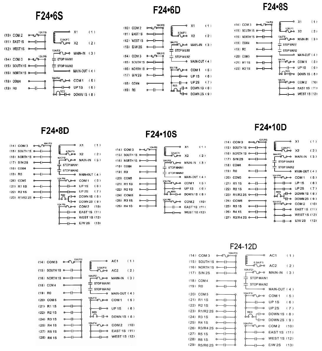
F24-12S
F24 Series Wiring Diagrams
Intercontinental Technologies Ltd. 558 Plate Drive Bldg. #2, East Dundee, IL 60118
Ph: 847-426-9597, Fax: 847-426-9724, TELECRANE.COM
normal, not interlocked
toggle (on/off)
off (on is button “UP”)
normal, interlocked with button “UP”
normal, not interlocked
toggle (on/off)
on (off is button “DOWN”)
normal, interlocked with button “DOWN”
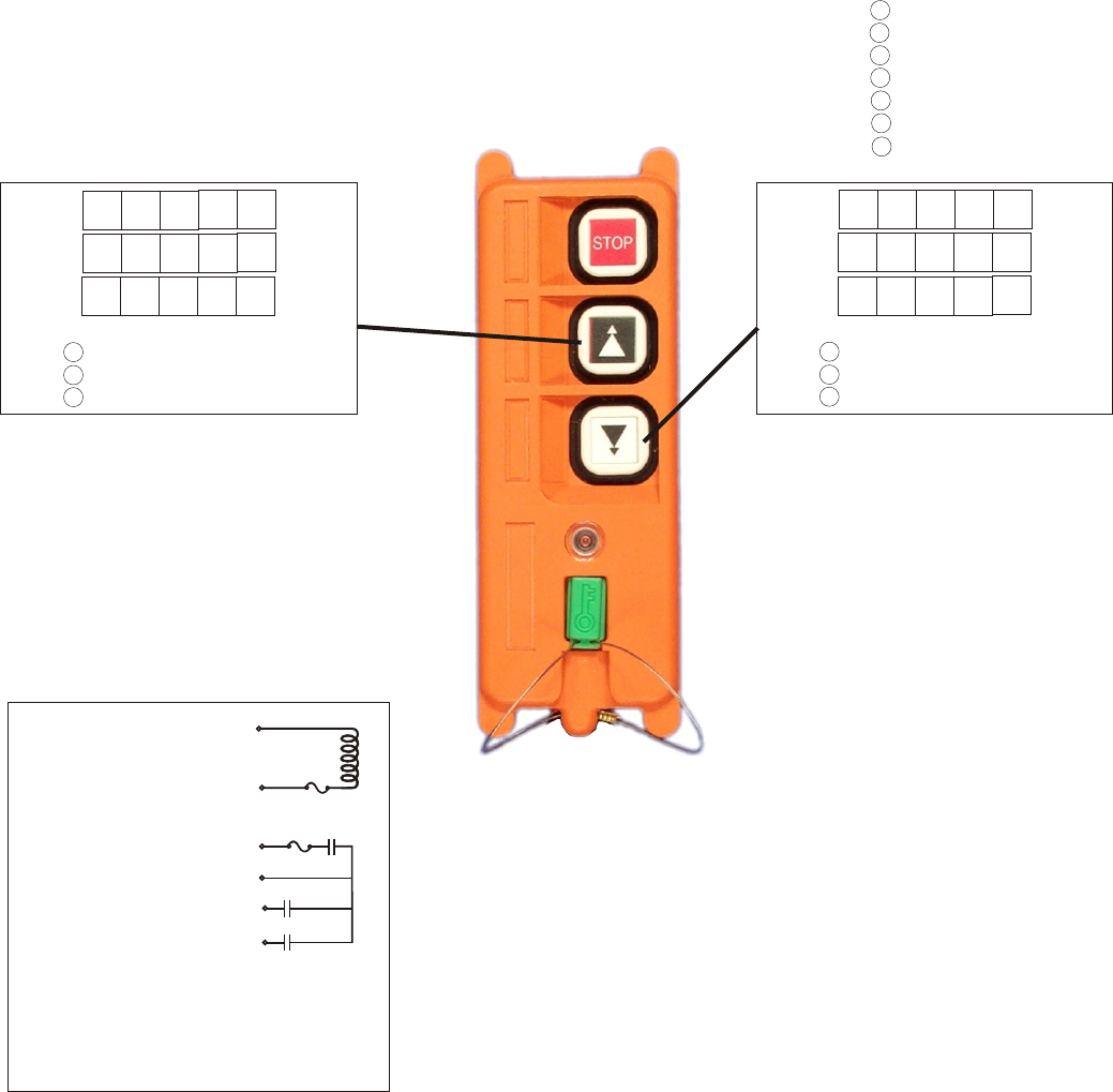
F21-2S
( ORANGE ) COM
( RED ) MAIN
( YELLOW ) UP
( BLUE ) DOWN
0.5A
10A
F21-2S Wire Diagram
( BLACK ) POWER 1
(WHITE ) POWER 2
110VAC Standard
10 minutes
20 minutes
30 minutes
1 hour
2 hours
3 hours
4 hours
Auto Shut Down time
Default setting : Never
NOTES: For each button there is a default function setting labeled in bold, if you wish to change any button function check the appropriate circle for that button.
If you want to re-label any button, fill in the squares in the appropriate section. Use only the squares available.
Intercontinental Technologies Ltd. 558 Plate Drive Bldg. #2, East Dundee, IL 60118
Ph: 847-426-9597, Fax: 847-426-9724, TELECRANE.COM
This page intentionally left blank.
normal, not interlocked
toggle (on/off)
off (on is button “UP”)
normal, interlocked with button “UP”
normal, not interlocked
toggle (on/off)
on (off is button “DOWN”)
normal, interlocked with button “DOWN”
.5 seconds
1 second
1.5 seconds
2 seconds
3 seconds
4 seconds
Acceleration delay for all button relays.
Default setting of ZERO seconds
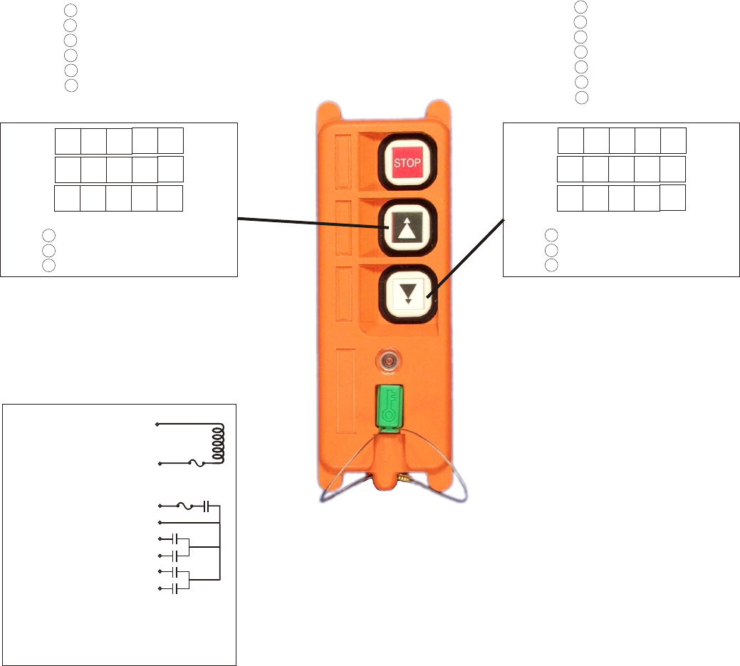
F21-2D
( ORANGE) COM
( RED ) MAIN
( YELLOW ) UP 1S
( GREEN ) UP 2S
( BLUE ) DOWN 1S
( PURPLE ) DOWN 2S
0.5A
10A
F21-2D Wire Diagram
( BLACK ) POWER 1
( BROWN ) POWER 2
110VAC Standard
10 minutes
20 minutes
30 minutes
1 hour
2 hours
3 hours
4 hours
Auto Shut Down time
Default setting : Never
NOTES: For each button there is a default function setting labeled in bold, if you wish to change any button function check the appropriate circle for that button.
If you want to re-label any button, fill in the squares in the appropriate section. Use only the squares available.
Intercontinental Technologies Ltd. 558 Plate Drive Bldg. #2, East Dundee, IL 60118
Ph: 847-426-9597, Fax: 847-426-9724, TELECRANE.COM
This page intentionally left blank.
normal, not interlocked
toggle (on/off)
off (on is button “UP”)
normal, interlocked with button “UP”
normal, not interlocked
toggle (on/off)
off (on is button “EAST”)
normal, interlocked with button “EAST”
normal, not interlocked
toggle (on/off)
on (off is button “DOWN”)
normal, interlocked with button “DOWN”
normal, not interlocked
toggle (on/off)
on (off is button “WEST”)
normal, interlocked with button “WEST”
toggle (on/off) of Relay R0
Start key second function setting
Default setting normal momentary control of R0
inching .1 seconds
inching .2 seconds
inching .3 seconds
inching .4 seconds
inching .6 seconds
inching .7 seconds
inching .8 seconds
inching .9 seconds
inching .5 seconds
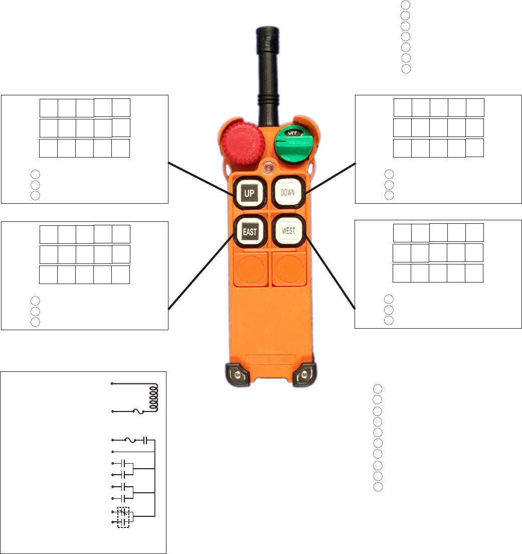
F21-4S
( ORANGE) COM
( RED ) MAIN
( YELLOW ) UP
( GREEN ) DOWN
( BLUE ) EAST
( PURPLE ) WEST
F21-4S Wire Diagram
0.5A
10A
( PINK ) R0
( BLACK ) POWER 1
( BROWN ) POWER 2
110VAC Standard
10 minutes
20 minutes
30 minutes
1 hour
2 hours
3 hours
4 hours
Auto Shut Down time
Default setting : Never
NOTES: For each button there is a default function setting labeled in bold, if you wish to change any button function check the appropriate circle for that button.
If you want to re-label any button, fill in the squares in the appropriate section. Use only the squares available.
Intercontinental Technologies Ltd. 558 Plate Drive Bldg. #2, East Dundee, IL 60118
Ph: 847-426-9597, Fax: 847-426-9724, TELECRANE.COM
This page intentionally left blank.
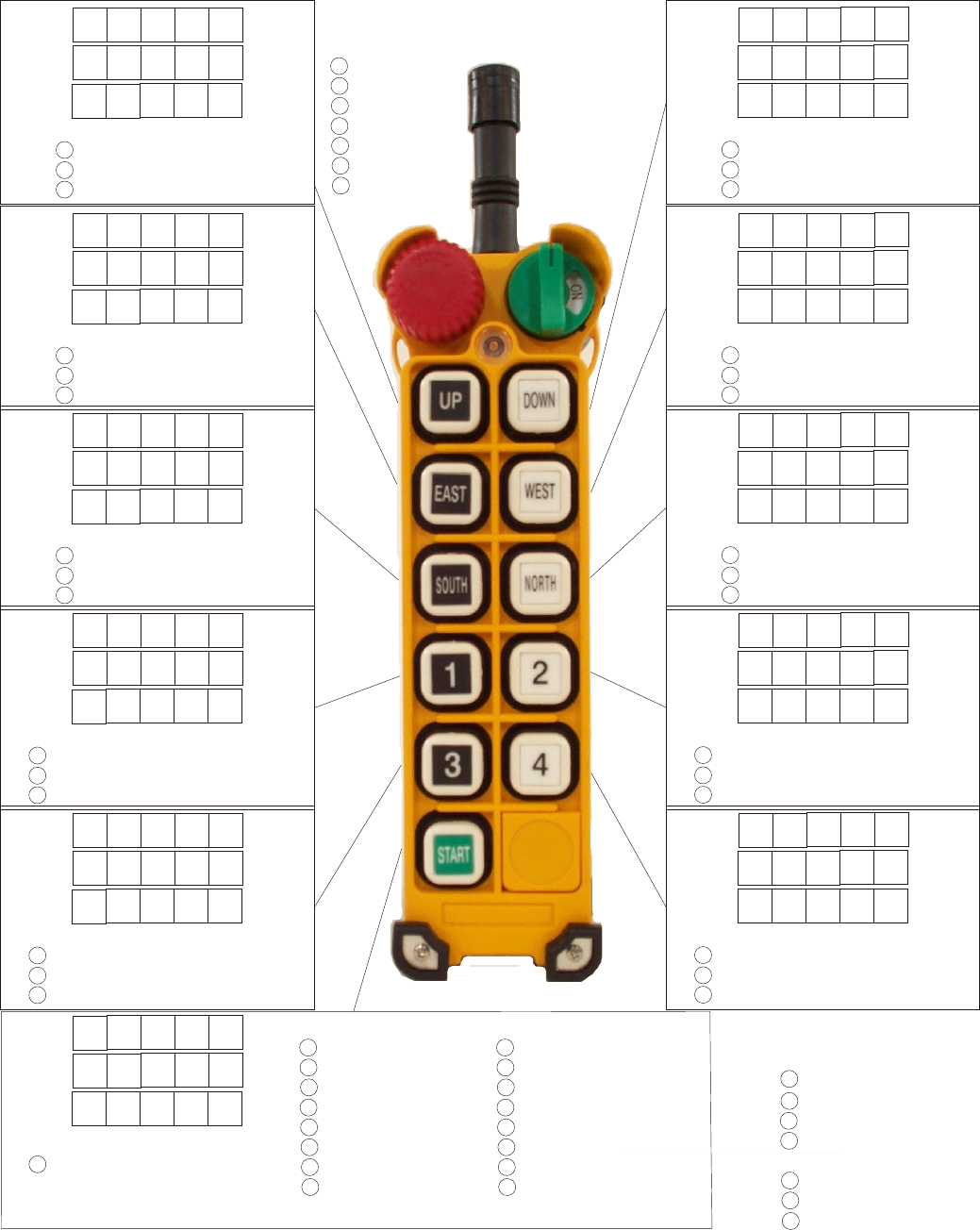
normal, not interlocked
toggle (on/off)
off (on is button “UP”)
normal, interlocked with button “UP”
normal, not interlocked
toggle (on/off)
off (on is button “EAST”)
normal, interlocked with button “EAST”
normal, not interlocked
toggle (on/off)
on (off is button “DOWN”)
normal, interlocked with button “DOWN”
normal, not interlocked
toggle (on/off)
on (off is button “WEST”)
normal, interlocked with button “WEST”
toggle (on/off) of Relay R0
inching .1 seconds
inching .2 seconds
inching .3 seconds
inching .4 seconds
inching .6 seconds
inching .7 seconds
inching .8 seconds
inching .9 seconds
inching .5 seconds
.5 seconds
1 second
1.5 seconds
2 seconds
3 seconds
4 seconds
Acceleration delay for all button relays.
Default setting of ZERO seconds
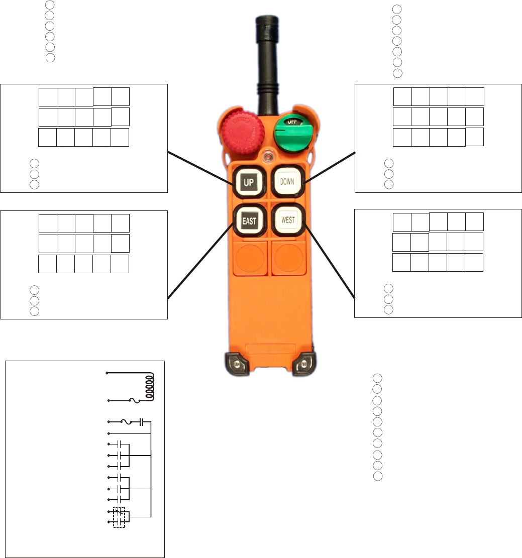
F21-4D
F21-4D Wire Diagram
0.5A
10A
( BLACK ) POWER 1
( ORANGE) COM
( RED ) MAIN
( YELLOW ) UP
( GREEN ) DOWN
( GREY ) U/D 2S
( BLUE ) EAST
( PURPLE ) WEST
( WHITE ) E/W 2S
( PINK ) R0
( BROWN ) POWER 2
110VAC Standard
Start key second function setting
Default setting normal momentary control of R0
10 minutes
20 minutes
30 minutes
1 hour
2 hours
3 hours
4 hours
Auto Shut Down time
Default setting : Never
NOTES: For each button there is a default function setting labeled in bold, if you wish to change any button function check the appropriate circle for that button.
If you want to re-label any button, fill in the squares in the appropriate section. Use only the squares available.
Intercontinental Technologies Ltd. 558 Plate Drive Bldg. #2, East Dundee, IL 60118
Ph: 847-426-9597, Fax: 847-426-9724, TELECRANE.COM
This page intentionally left blank.
normal, not interlocked
toggle (on/off)
off (on is button “UP”)
normal, interlocked with button “UP”
normal, not interlocked
toggle (on/off)
off (on is button “EAST”)
normal, interlocked with button “EAST”
normal, not interlocked
toggle (on/off)
on (off is button “DOWN”)
normal, interlocked with button “DOWN”
normal, not interlocked
toggle (on/off)
on (off is button “WEST”)
normal, interlocked with button “WEST”
normal, not interlocked
toggle (on/off)
on (off is button “SOUTH”)
normal, interlocked with button “NORTH”
normal, not interlocked
toggle (on/off)
on (off is button “SOUTH”)
normal, interlocked with button “SOUTH”
toggle (on/off) of Relay R0
Start key second function setting
Default setting normal momentary control of R0
inching .1 seconds
inching .2 seconds
inching .3 seconds
inching .4 seconds
inching .6 seconds
inching .7 seconds
inching .8 seconds
inching .9 seconds
inching .5 seconds
10 minutes
20 minutes
30 minutes
1 hour
2 hours
3 hours
4 hours
Auto Shut Down time
Default setting : Never
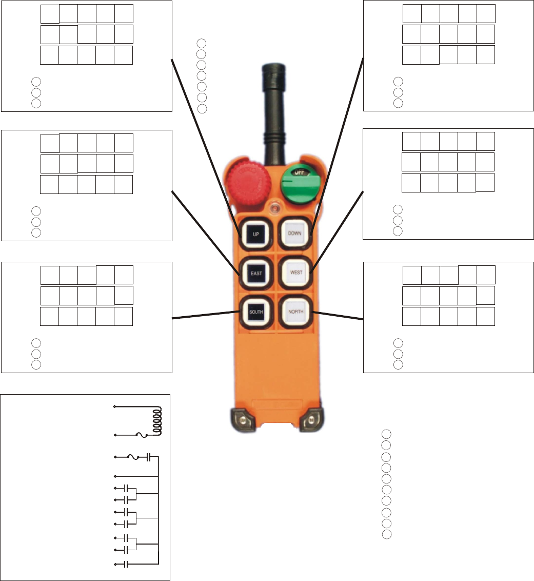
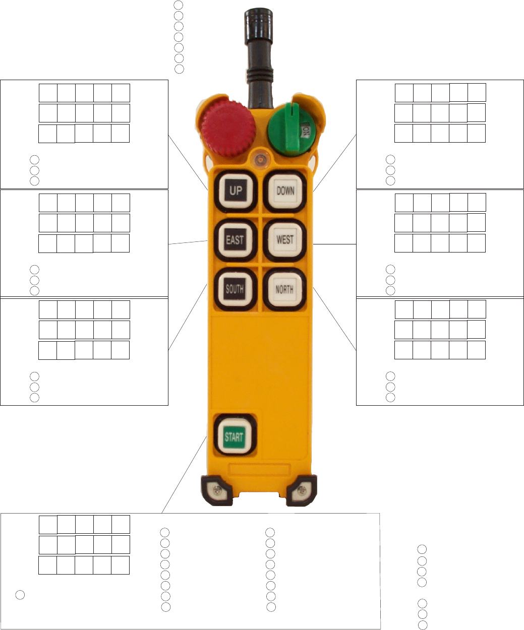
F21-6S
( RED ) MAIN
( YELLOW ) UP
( GREEN ) DOWN
( BLUE ) EAST
( PURPLE ) WEST
F21-6S Wire Diagram
0.5A
10A
( PINK ) R0
( BLACK ) POWER 1
( BROWN ) POWER 2
110VAC Standard
( GRAY ) SOUTH
( WHITE ) NORTH
( ORANGE) COM
NOTES: For each button there is a default function setting labeled in bold, if you wish to change any button function check the appropriate circle for that button.
If you want to re-label any button, fill in the squares in the appropriate section. Use only the squares available.
Intercontinental Technologies Ltd. 558 Plate Drive Bldg. #2, East Dundee, IL 60118
Ph: 847-426-9597, Fax: 847-426-9724, TELECRANE.COM
This page intentionally left blank.
normal, not interlocked
toggle (on/off)
off (on is button “UP”)
normal, interlocked with button “UP”
normal, not interlocked
toggle (on/off)
off (on is button “EAST”)
normal, interlocked with button “EAST”
normal, not interlocked
toggle (on/off)
off (on is button “SOUTH”)
normal, interlocked with button “SOUTH”
normal, not interlocked
toggle (on/off)
on (off is button “DOWN”)
normal, interlocked with button “DOWN”
normal, not interlocked
toggle (on/off)
on (off is button “WEST”)
normal, interlocked with button “WEST”
normal, not interlocked
toggle (on/off)
on (off is button “NORTH”)
normal, interlocked with button “NORTH”
normal
toggle (on/off)
inching .4 seconds
inching .5 seconds
inching .6 seconds
inching .1 seconds
inching .7 seconds
inching .2 seconds
inching .8 seconds
inching .3 seconds
10 minutes
20 minutes
30 minutes
1 hour
2 hours
3 hours
4 hours
Auto Shut Down time
Default setting of 1 hour
never
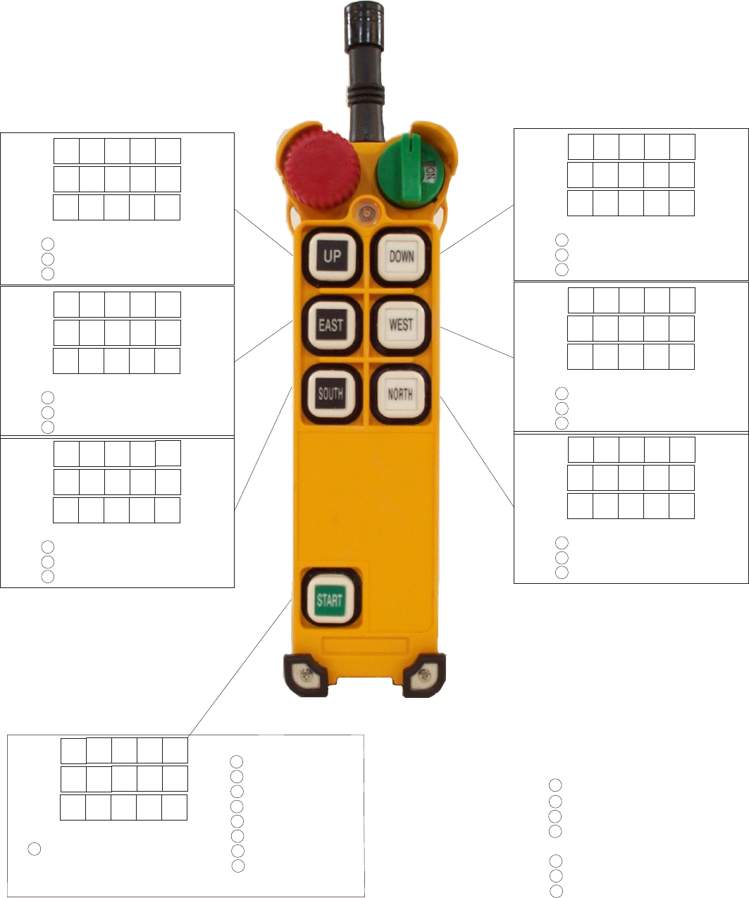
F24-6S
NOTES: For each button there is a default function setting labeled in bold, if you wish to change any button function check the appropriate circle for that button.
If you want to re-label any button, fill in the squares in the appropriate section. Use only the squares available.
Intercontinental Technologies Ltd. 558 Plate Drive Bldg. #2, East Dundee, IL 60118
Ph: 847-426-9597, Fax: 847-426-9724, TELECRANE.COM
This page intentionally left blank.
normal, not interlocked
toggle (on/off)
off (on is button “UP”)
normal, interlocked with button “UP”
normal, not interlocked
toggle (on/off)
off (on is button “EAST”)
normal, interlocked with button “EAST”
normal, not interlocked
toggle (on/off)
off (on is button “SOUTH”)
normal, interlocked with button “SOUTH”
normal, not interlocked
toggle (on/off)
on (off is button “DOWN”)
normal, interlocked with button “DOWN”
normal, not interlocked
toggle (on/off)
on (off is button “WEST”)
normal, interlocked with button “WEST”
normal, not interlocked
toggle (on/off)
on (off is button “NORTH”)
normal, interlocked with button “NORTH”
normal
toggle (on/off)
inching .4 seconds
inching .5 seconds
inching .6 seconds
inching .1 seconds
inching .7 seconds
inching .2 seconds
inching .8 seconds
inching .3 seconds
acceleration .4 seconds
acceleration .5 seconds
acceleration .6 seconds
acceleration .1 seconds
acceleration .7 seconds
acceleration .2 seconds
acceleration .8 seconds
acceleration .3 seconds
Acceleration delay for all button relays.
Default setting of ZERO
10 minutes
20 minutes
30 minutes
1 hour
2 hours
3 hours
4 hours
Auto Shut Down time
Default setting of 1 hour
never
1.5 seconds
2 seconds
3 seconds
.3 seconds
4 seconds
.5 seconds
1 second
F24-6D
NOTES: For each button there is a default function setting labeled in bold, if you wish to change any button function check the appropriate circle for that button.
If you want to re-label any button, fill in the squares in the appropriate section. Use only the squares available.
Intercontinental Technologies Ltd. 558 Plate Drive Bldg. #2, East Dundee, IL 60118
Ph: 847-426-9597, Fax: 847-426-9724, TELECRANE.COM
This page intentionally left blank.
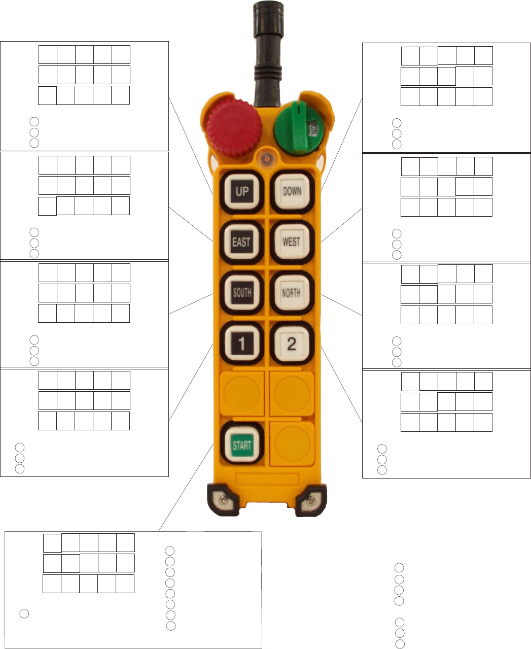
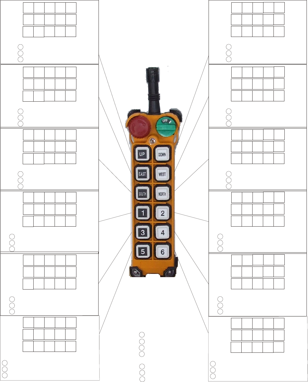
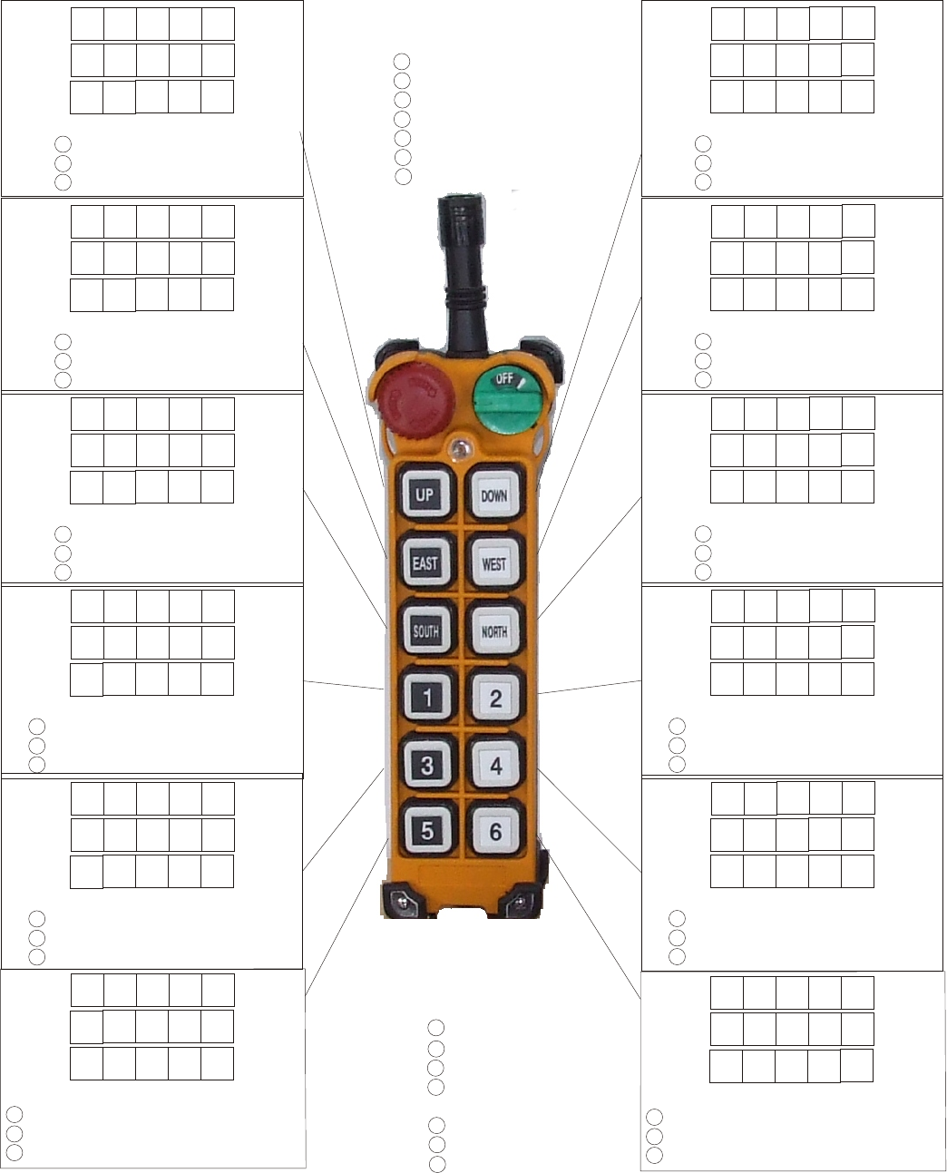
normal, not interlocked
toggle (on/off)
off (on is button “UP”)
normal, interlocked with button “UP”
normal, not interlocked
toggle (on/off)
off (on is button “EAST”)
normal, interlocked with button “EAST”
normal, not interlocked
toggle (on/off)
off (on is button “SOUTH”)
normal, interlocked with button “SOUTH”
normal, not interlocked
toggle (on/off)
off (on is button “1”)
normal, interlocked with button “1”
normal, not interlocked
toggle (on/off)
on (off is button “DOWN”)
normal, interlocked with button “DOWN”
normal, not interlocked
toggle (on/off)
on (off is button “WEST”)
normal, interlocked with button “WEST”
normal, not interlocked
toggle (on/off)
on (off is button “NORTH”)
normal, interlocked with button “NORTH”
normal, not interlocked
toggle (on/off)
on (off is button 2)
normal, interlocked with button “2”
normal
toggle (on/off)
inching .4 seconds
inching .5 seconds
inching .6 seconds
inching .1 seconds
inching .7 seconds
inching .2 seconds
inching .8 seconds
inching .3 seconds
10 minutes
20 minutes
30 minutes
1 hour
2 hours
3 hours
4 hours
Auto Shut Down time
Default setting of 1 hour
never
F24-8S
NOTES: For each button there is a default function setting labeled in bold, if you wish to change any button function check the appropriate circle for that button.
If you want to re-label any button, fill in the squares in the appropriate section. Use only the squares available.
Intercontinental Technologies Ltd. 558 Plate Drive Bldg. #2, East Dundee, IL 60118
Ph: 847-426-9597, Fax: 847-426-9724, TELECRANE.COM
This page intentionally left blank.
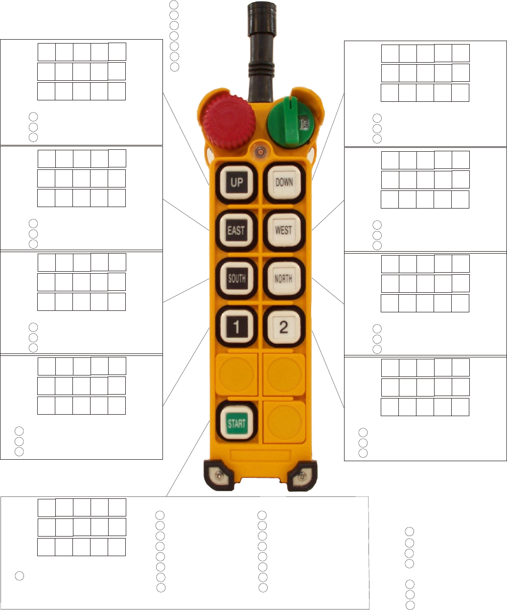
normal, not interlocked
toggle (on/off)
off (on is button “UP”)
normal, interlocked with button “UP”
normal, not interlocked
toggle (on/off)
off (on is button “EAST”)
normal, interlocked with button “EAST”
normal, not interlocked
toggle (on/off)
off (on is button “SOUTH”)
normal, interlocked with button “SOUTH”
normal, not interlocked
toggle (on/off)
off (on is button “1”)
normal, interlocked with button “1”
normal, not interlocked
toggle (on/off)
on (off is button “DOWN”)
normal, interlocked with button “DOWN”
normal, not interlocked
toggle (on/off)
on (off is button “WEST”)
normal, interlocked with button “WEST”
normal, not interlocked
toggle (on/off)
on (off is button “NORTH”)
normal, interlocked with button “NORTH”
normal, not interlocked
toggle (on/off)
on (off is button 2)
normal, interlocked with button “2”
normal
toggle (on/off)
inching .4 seconds
inching .5 seconds
inching .6 seconds
inching .1 seconds
inching .7 seconds
inching .2 seconds
inching .8 seconds
inching .3 seconds
acceleration .4 seconds
acceleration .5 seconds
acceleration .6 seconds
acceleration .1 seconds
acceleration .7 seconds
acceleration .2 seconds
acceleration .8 seconds
acceleration .3 seconds
Acceleration delay for all button relays.
Default setting of ZERO
10 minutes
20 minutes
30 minutes
1 hour
2 hours
3 hours
4 hours
Auto Shut Down time
Default setting of 1 hour
never
1.5 seconds
2 seconds
3 seconds
.3 seconds
4 seconds
.5 seconds
1 second
F24-8D
NOTES: For each button there is a default function setting labeled in bold, if you wish to change any button function check the appropriate circle for that button.
If you want to re-label any button, fill in the squares in the appropriate section. Use only the squares available.
Intercontinental Technologies Ltd. 558 Plate Drive Bldg. #2, East Dundee, IL 60118
Ph: 847-426-9597, Fax: 847-426-9724, TELECRANE.COM
This page intentionally left blank.
normal, not interlocked
toggle (on/off)
off (on is button “UP”)
normal, interlocked with button “UP”
normal, not interlocked
toggle (on/off)
off (on is button “EAST”)
normal, interlocked with button “EAST”
normal, not interlocked
toggle (on/off)
off (on is button “SOUTH”)
normal, interlocked with button “SOUTH”
normal, not interlocked
toggle (on/off)
off (on is button “1”)
normal, interlocked with button “1”
normal, not interlocked
toggle (on/off)
on (off is button “DOWN”)
normal, interlocked with button “DOWN”
normal, not interlocked
toggle (on/off)
on (off is button “WEST”)
normal, interlocked with button “WEST”
normal, not interlocked
toggle (on/off)
on (off is button “NORTH”)
normal, interlocked with button “NORTH”
normal, not interlocked
toggle (on/off)
on (off is button 2)
normal, interlocked with button “2”
normal, not interlocked
toggle (on/off)
on (off is button “4”)
normal, interlocked with button “4”
normal, not interlocked
toggle (on/off)
off (on is button “3”)
normal interlocked with button “3”
normal
toggle (on/off)
inching .4 seconds
inching .5 seconds
inching .6 seconds
inching .1 seconds
inching .7 seconds
inching .2 seconds
inching .8 seconds
inching .3 seconds
10 minutes
20 minutes
30 minutes
1 hour
2 hours
3 hours
4 hours
Auto Shut Down time
Default setting of 1 hour
never
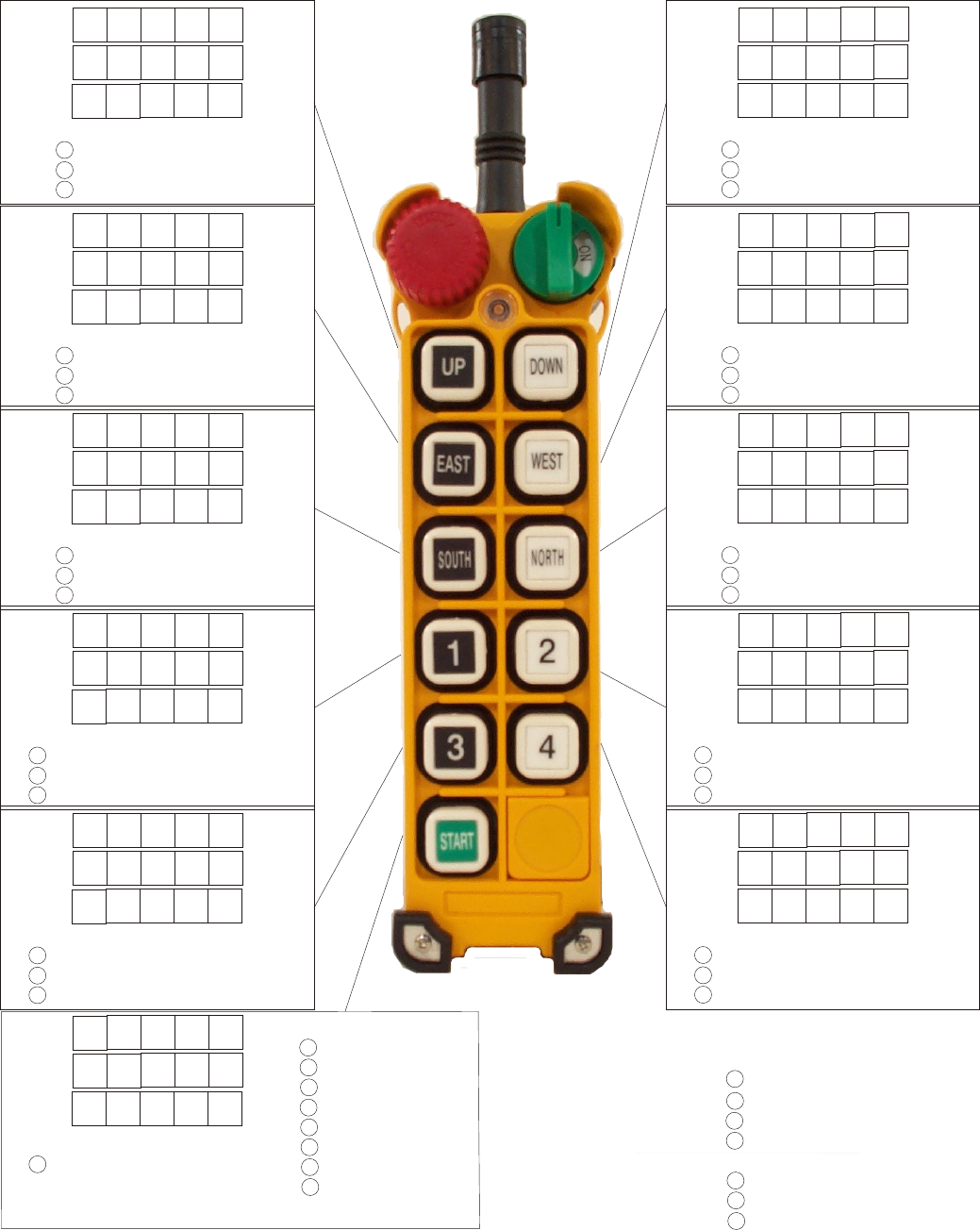
F24-10S
NOTES: For each button there is a default function setting labeled in bold, if you wish to change any button function check the appropriate circle for that button.
If you want to re-label any button, fill in the squares in the appropriate section. Use only the squares available.
Intercontinental Technologies Ltd. 558 Plate Drive Bldg. #2, East Dundee, IL 60118
Ph: 847-426-9597, Fax: 847-426-9724, TELECRANE.COM
This page intentionally left blank.
normal, not interlocked
toggle (on/off)
off (on is button “UP”)
normal, interlocked with button “UP”
normal, not interlocked
toggle (on/off)
off (on is button “EAST”)
normal, interlocked with button “EAST”
normal, not interlocked
toggle (on/off)
off (on is button “SOUTH”)
normal, interlocked with button “SOUTH”
normal, not interlocked
toggle (on/off)
off (on is button “1”)
normal, interlocked with button “1”
normal, not interlocked
toggle (on/off)
on (off is button “DOWN”)
normal, interlocked with button “DOWN”
normal, not interlocked
toggle (on/off)
on (off is button “WEST”)
normal, interlocked with button “WEST”
normal, not interlocked
toggle (on/off)
on (off is button “NORTH”)
normal, interlocked with button “NORTH”
normal, not interlocked
toggle (on/off)
on (off is button 2)
normal, interlocked with button “2”
normal, not interlocked
toggle (on/off)
on (off is button “4”)
normal, interlocked with button “4”
normal, not interlocked
toggle (on/off)
off (on is button “3”)
normal interlocked with button “3”
normal
toggle (on/off)
inching .4 seconds
inching .5 seconds
inching .6 seconds
inching .1 seconds
inching .7 seconds
inching .2 seconds
inching .8 seconds
inching .3 seconds
acceleration .4 seconds
acceleration .5 seconds
acceleration .6 seconds
acceleration .1 seconds
acceleration .7 seconds
acceleration .2 seconds
acceleration .8 seconds
acceleration .3 seconds
Acceleration delay for all button relays.
Default setting of ZERO
10 minutes
20 minutes
30 minutes
1 hour
2 hours
3 hours
4 hours
Auto Shut Down time
Default setting of 1 hour
never
1.5 seconds
2 seconds
3 seconds
.3 seconds
4 seconds
.5 seconds
1 second
F24-10D
NOTES: For each button there is a default function setting labeled in bold, if you wish to change any button function check the appropriate circle for that button.
If you want to re-label any button, fill in the squares in the appropriate section. Use only the squares available.
Intercontinental Technologies Ltd. 558 Plate Drive Bldg. #2, East Dundee, IL 60118
Ph: 847-426-9597, Fax: 847-426-9724, TELECRANE.COM
This page intentionally left blank.
normal, not interlocked
toggle (on/off)
off (on is button “UP”)
normal, interlocked with button “UP”
normal, not interlocked
toggle (on/off)
off (on is button “EAST”)
normal, interlocked with button “EAST”
normal, not interlocked
toggle (on/off)
off (on is button “SOUTH”)
normal, interlocked with button “SOUTH”
normal, not interlocked
toggle (on/off)
off (on is button “1”)
normal, interlocked with button “1”
normal, not interlocked
toggle (on/off)
on (off is button “DOWN”)
normal, interlocked with button “DOWN”
normal, not interlocked
toggle (on/off)
on (off is button “WEST”)
normal, interlocked with button “WEST”
normal, not interlocked
toggle (on/off)
on (off is button “NORTH”)
normal, interlocked with button “NORTH”
normal, not interlocked
toggle (on/off)
on (off is button 2)
normal, interlocked with button “2”
normal, not interlocked
toggle (on/off)
on (off is button “4”)
normal, interlocked with button “4”
normal, not interlocked
toggle (on/off)
off (on is button “3”)
normal interlocked with button “3”
inching .4 seconds
inching .5 seconds
inching .6 seconds
inching .1 seconds
inching .7 seconds
inching .2 seconds
inching .8 seconds
inching .3 seconds
acceleration .4 seconds
acceleration .5 seconds
acceleration .6 seconds
acceleration .1 seconds
acceleration .7 seconds
acceleration .2 seconds
acceleration .8 seconds
acceleration .3 seconds
10 minutes
20 minutes
30 minutes
1 hour
2 hours
3 hours
4 hours
Auto Shut Down time
Default setting of 1 hour
never
F24-12S
NOTES: For each button there is a default function setting labeled in bold, if you wish to change any button function check the appropriate circle for that button.
If you want to re-label any button, fill in the squares in the appropriate section. Use only the squares available.
Intercontinental Technologies Ltd. 558 Plate Drive Bldg. #2, East Dundee, IL 60118
Ph: 847-426-9597, Fax: 847-426-9724, TELECRANE.COM
normal, not interlocked
toggle (on/off)
on (off is button “6”)
normal, interlocked with button “6”
normal, not interlocked
toggle (on/off)
on (off is button “5”)
normal, interlocked with button “5”
This page intentionally left blank.
normal, not interlocked
toggle (on/off)
off (on is button “UP”)
normal, interlocked with button “UP”
normal, not interlocked
toggle (on/off)
off (on is button “EAST”)
normal, interlocked with button “EAST”
normal, not interlocked
toggle (on/off)
off (on is button “SOUTH”)
normal, interlocked with button “SOUTH”
normal, not interlocked
toggle (on/off)
off (on is button “1”)
normal, interlocked with button “1”
normal, not interlocked
toggle (on/off)
on (off is button “DOWN”)
normal, interlocked with button “DOWN”
normal, not interlocked
toggle (on/off)
on (off is button “WEST”)
normal, interlocked with button “WEST”
normal, not interlocked
toggle (on/off)
on (off is button “NORTH”)
normal, interlocked with button “NORTH”
normal, not interlocked
toggle (on/off)
on (off is button 2)
normal, interlocked with button “2”
normal, not interlocked
toggle (on/off)
on (off is button “4”)
normal, interlocked with button “4”
normal, not interlocked
toggle (on/off)
off (on is button “3”)
normal interlocked with button “3”
inching .4 seconds
inching .5 seconds
inching .6 seconds
inching .1 seconds
inching .7 seconds
inching .2 seconds
inching .8 seconds
inching .3 seconds
acceleration .4 seconds
acceleration .5 seconds
acceleration .6 seconds
acceleration .1 seconds
acceleration .7 seconds
acceleration .2 seconds
acceleration .8 seconds
acceleration .3 seconds
Acceleration delay for all button relays.
Default setting of ZERO
10 minutes
20 minutes
30 minutes
1 hour
2 hours
3 hours
4 hours
Auto Shut Down time
Default setting of 1 hour
never
1.5 seconds
2 seconds
3 seconds
.3 seconds
4 seconds
.5 seconds
1 second
F24-12D
NOTES: For each button there is a default function setting labeled in bold, if you wish to change any button function check the appropriate circle for that button.
If you want to re-label any button, fill in the squares in the appropriate section. Use only the squares available.
Intercontinental Technologies Ltd. 558 Plate Drive Bldg. #2, East Dundee, IL 60118
Ph: 847-426-9597, Fax: 847-426-9724, TELECRANE.COM
normal, not interlocked
toggle (on/off)
on (off is button “6”)
normal, interlocked with button “6”
normal, not interlocked
toggle (on/off)
on (off is button “5”)
normal, interlocked with button “5”
This page intentionally left blank.
Intercontinental Technologies Ltd. 558 Plate Drive Bldg. #2, East Dundee, IL 60118
Ph: 847-426-9597, Fax: 847-426-9724, TELECRANE.COM