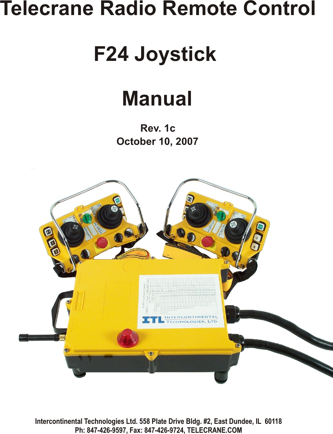
Intercontinental Technologies F24-J-016 Industrial Radio Remote Control Transmitter User Manual F21 2 and 4 Manual
Intercontinental Technologies Ltd Industrial Radio Remote Control Transmitter F21 2 and 4 Manual
UserManual.wiki
>
Intercontinental Technologies
>
F24 J 016 User Manual
User Manual
Navigation menu
Upload a User Manual
Namespaces
Wiki Guide
HTML
PDF
Info
Views
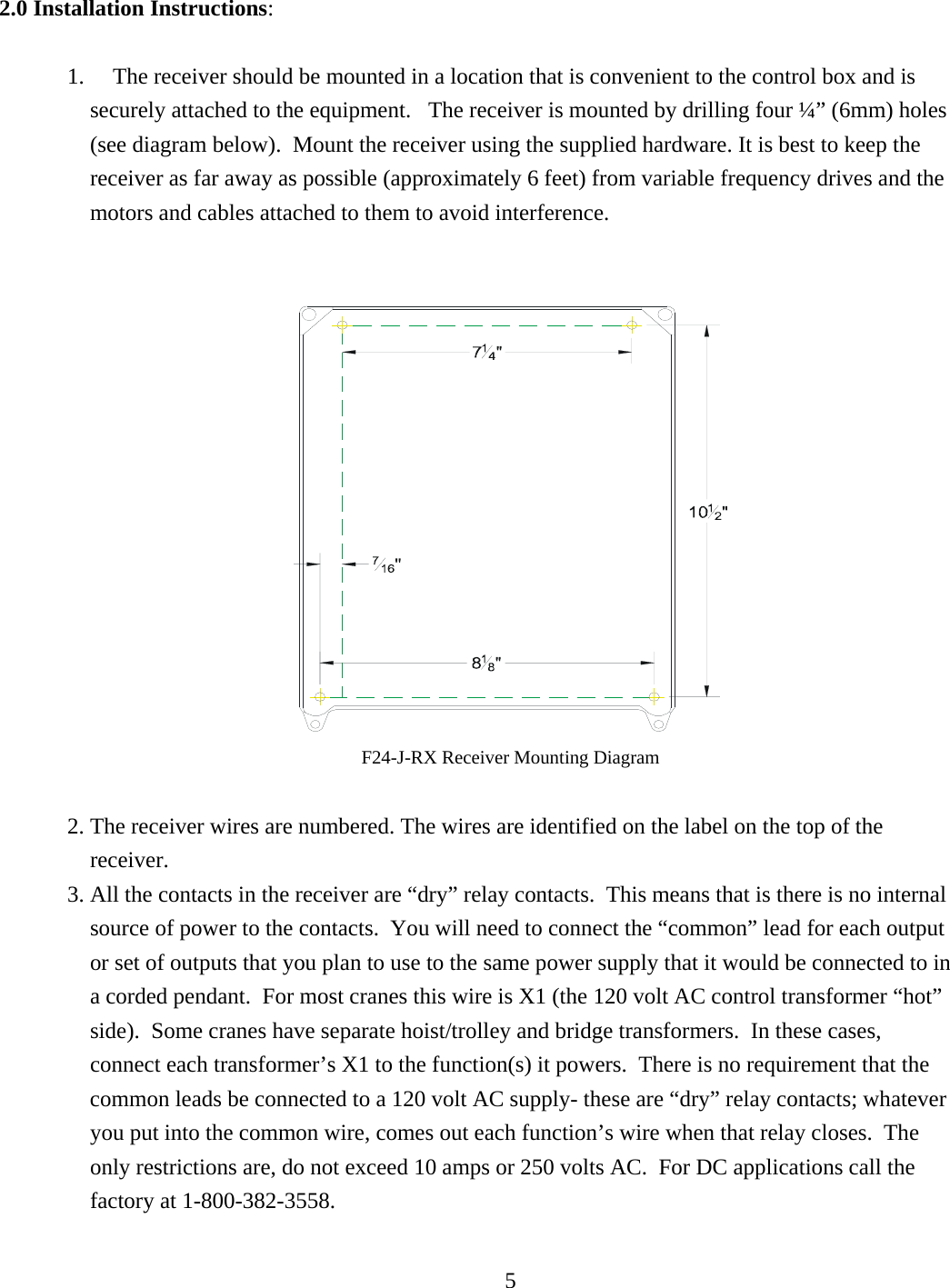
User Manual
Discussion / Help
Navigation