TruVision Stainless Steel PTZ Camera Configuration Manual 1073372b En
2018-06-15
: Interlogix 1073372B-Truvision-Stainless-Steel-Ptz-Camera-Configuration-Manual-En 1073372b-truvision-stainless-steel-ptz-camera-configuration-manual-en library
Open the PDF directly: View PDF ![]() .
.
Page Count: 79

TruVision Stainless Steel PTZ
Camera Configuration Manual
P/N 1073372-EN • REV B • ISS 23MAR18
Copyright
©
2018 United Technologies Corporation.
Interlogix is part of UTC
Climate, Controls & Security, a unit of Un
ited
Technologies Corporation.
All rights reserved.
Trademarks and
patents
T
rade names used in this document may be trademarks or
registered trademarks of the manufacturers or vendors of the
respective products.
Manufacturer
Interlogix
2955 Red Hill Avenue, Costa Mesa, CA 92626
-5923, USA
Authorized EU manufacturing representative:
UTC
Building & Industrial Systems B.V.
Kelvinstraat 7, 6003 DH Weert, The Netherlands
Certification
Product warnings and
disclaimers
THESE PRODUCTS ARE INTENDED FOR SALE TO AND
INSTALLATION BY QUALIFIED PROFESSIONALS. UTC FIRE &
SECURITY CANNOT PROVIDE ANY ASSURANCE THAT ANY
PERSON OR ENTITY BUYING ITS PRODUCTS, INCLUDING ANY
“AUTHORIZED DEALER” OR “AUTHORIZED RESELLER”, IS
PROPERLY TRA
INED OR EXPERIENCED TO CORRECTLY
INSTALL FIRE AND SECURITY RELATED PRODUCTS.
For more information on warranty disclaimers and product safety
information, please check
www.firesecurityproducts.com
/policy/product-warning/ or scan the
following code:
Contact information
and manuals
For contact information go to: www.interlogix.com or
www.firesecurityproducts.com
.
To get translations for this and other product manuals go to:
www.firesecurityproducts.com
.
Content
Introduction 2
Default settings to access the camera 2
Network access 3
Checking web browser security level 3
Activating the camera 4
Overview of the camera web browser 5
Camera configuration 7
Configuration panel overview 7
System time 11
RS485 12
Network settings 13
Video/Audio 20
Image 23
PTZ parameters 28
Basic event 36
Smart event 43
Schedule settings 50
Storage management 53
Camera management 56
User management 56
Security 59
Maintenance 61
Camera operation 64
Logging on and off 64
Live view mode 65
Playing back recorded video 67
Operating PTZ control 68
Picture 74
TruVision Stainless Steel PTZ Camera Configuration Manual 1
Introduction
This is the configuration manual for the following TruVision® IP camera models:
IP stainless steel PTZ camera:
TVP-5201
Default settings to access the camera
Default credentials
The camera comes with a user account with administrative rights for configuring all
options on the camera. The user name is “admin” and the password is “1234.” For
enhanced security, we highly recommend changing the default password during initial
setup.
Default network settings
The network settings are:
• IP address (in a network without a DHCP server): 192.168.1.70
• Subnet mask: 255.255.255.0
• Gateway address: 192.168.1.1
Ports used:
Browser TruVision Navigator
RTSP: 554 RTSP: 554
HTTP: 80 Server/client control port: 8000
2 TruVision Stainless Steel PTZ Camera Configuration Manual
Network access
This manual explains how to configure the camera over the network with a web
browser.
TruVision IP cameras can be configured and controlled using Microsoft® Internet
Explorer® (IE) and other browsers. The procedures described use the Microsoft Internet
Explorer (IE) web browser.
Checking web browser security level
When using the web browser interface, ActiveX controls can be installed to connect and
view video using Internet Explorer. However, data such as video and images cannot be
downloaded due to the increased security measure. Check the security level of the PC
to enable interaction with the cameras over the web and, if necessary, modify the
Active X settings.
Configuring IE ActiveX controls
Confirm the ActiveX settings of the web browser.
To change the web browser’s security level:
1. In Internet Explorer, click Internet Options on the Tools menu.
2. On the Security tab, click the zone to be assigned to a website under “Select a web
content zone to specify its security settings.”
3. Click Custom Level.
4. Change the ActiveX controls and plug-ins options that are signed or marked as
safe to Enable. Change the ActiveX controls and plug-ins options that are
unsigned to Prompt or Disable. Click OK.
—or—
Under Reset Custom Settings, click the security level for the whole zone in the
Reset To box, and then select Medium. Click Reset, and then click OK in the
Internet Options Security tab window.
5. Click Apply in the Internet Options Security tab window.
Windows users
Internet Explorer for Windows® operating systems have increased security measures to
protect a PC from malicious software.
To ensure complete functionality of the Windows web browser interface, do the
following:
• Run IE as an administrator in the workstation
• Add the camera’s IP address to the IE’s list of trusted sites
TruVision Stainless Steel PTZ Camera Configuration Manual 3

To add the camera’s IP address to Internet Explorer’s list of trusted sites:
1. Open Internet Explorer.
2. Click Tools, and then click Internet Options.
3. Click the Security tab, and then select the Trusted sites icon.
4. Click the Sites button.
5. Deselect the Require server verification (https:) for all sites in this zone check
box.
6. Type the IP address in the Add this website to the zone box.
7. Click Add, and then click Close.
8. Click OK in the Internet Options dialog window.
9. Connect to the camera for full browser functionality.
Activating the camera
When you first start up the camera, the Activation window appears. You must define a
high-security admin password before you can access the camera. There is no default
password provided.
You can activate a password via a web browser and via TruVision Device Manager
(included on the CD to find the IP address of the camera).
Activation via the web browser:
1. Power on the camera and connect the camera to the network.
2. Type the IP address into the address bar of the web browser, and press Enter to
enter the activation interface.
Note:
The default IP address of the camera is 192.168.1.70.
For the camera to enable DHCP by default, you must activate the camera via
TruVision Device Manager. Please refer to the following section, “Activation via
TruVision Device Manager”.
4 TruVision Stainless Steel PTZ Camera Configuration Manual
3. Type the password in the Password field.
Note: A valid password range must be between 8 and 16 characters. You can use a
combination of numbers, lower and upper case letters, and special characters : _ - ,
. * & @ / $ ? Space. The password must contain characters from at least two of
these groups. We also recommend that you reset your password regularly. For high
security systems, it is particularly recommended to reset the password monthly or
weekly for better protection.
4. Confirm the password.
5. Click OK to save the password and enter the live view interface.
Activation via TruVision Device Manager:
For instructions on how to activate the camera using TruVision Device Manager, refer
to the TruVision Device Manager User Manual.
Go to www.interlogix.com/video/product/truvision-device-manager and click
Downloads.
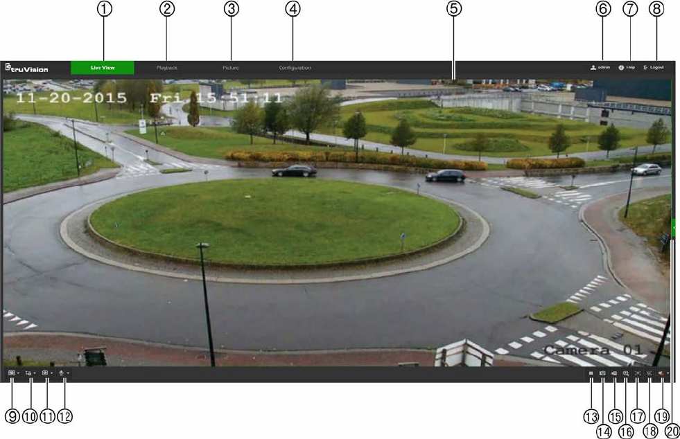
Overview of the camera web browser
Use the camera web browser to view, record, and play back recorded videos as well as
manage the camera from any PC with access to the same network as the camera. The
browser’s easy-to-use controls provide quick access to all camera functions.
If there is more than one camera connected over the network, open a separate web
browser window for each individual camera.
TruVision Stainless Steel PTZ Camera Configuration Manual 5

Name
Description
1. Live view tab Click to view live video.
2. Playback tab Click to play back video.
3. Picture tab Click to search for snapshots.
4. Configuration tab Click to display the configuration window for setting up the camera.
5. Viewer View live video. Time, date, and camera name are displayed here.
6. Current user Displays current user logged on.
7. Help Click to see user instructions.
8. Logout Click to log out from the system. This can be done at any time.
9. Aspect ratio Click this drop-down list to select an aspect ratio (4:3, 16:9,
Original, or Auto) and adjust the layout of the live view.
10. Stream type Click this drop-down list to select main stream or sub stream.
11. Plug-in switch Click this drop-down list to select the plug-in.
For IE users, web components and QuickTime are selectable. For
non-IE users, web components, QuickTime, VLC, or MJPEG are
selectable if they are supported by the web browser.
12. Bi-directional audio Turn the microphone on or off.
13. Start/stop live view Click to start/stop live view.
14. Snapshot Click to take a snapshot of the video. The snapshot will be saved to
the default folder in JPEG or BMP format.
15. Start/stop recording Click to record live video.
16. Digital zoom Click to enable digital zoom.
17. Enable Regional
Exposure Click this button and drag the cursor in the Viewer to adjust the
exposure settings for live video.
18. Enable Regional
Focus Click this button and drag the cursor in the Viewer to adjust the
focus settings for live video.
19. Audio Adjust the volume.
20. PTZ controls Direction actions, zoom, focus, iris, light, and wiper control.
6 TruVision Stainless Steel PTZ Camera Configuration Manual
Camera configuration
This chapter explains how to configure the cameras using a web browser.
After the camera hardware has been installed, configure the camera’s settings using
the web browser. Administrator rights are required to configure the cameras over the
internet.
The camera web browser permits configuration of the camera remotely using a PC.
Web browser options may vary depending on camera model.
Configuration panel overview
Use the Configuration panel to configure the server, network, camera settings, alarms,
users, transactions, and other parameters such as upgrading the firmware.
This section contains images and descriptions of each of the configuration panel
windows.
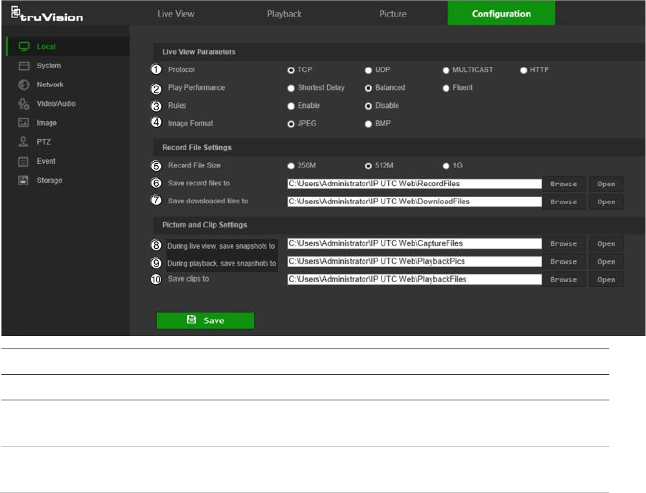
Local
Use the Local window to manage the protocol type, live view performance, and local
storage paths. In the Configuration panel, click Local to display the local configuration
window.
Parameters Description
Live View Parameters
1.
Protocol
Specifies the network protocol used.
Options include: TCP, UDP, MULTICAST, and HTTP.
2.
Live View Performance
Specifies the transmission speed.
Options include: Shortest Delay or Auto.
TruVision Stainless Steel PTZ Camera Configuration Manual 7
Parameters Description
3.
Rules
Specifies Live View display rules. Select Enable to tag a
moving object with green rectangles.
4.
Image Format
Choose the image format for a snapshot: JPEG or BMP.
Record File Settings
5.
Record F
ile Size Specifies the maximum file size.
Options include: 256M, 512M, and 1G.
6.
Save
Record Files to Specifies the directory for recorded files.
7.
Save
Downloaded Files to Specifies the directory for downloaded files.
Picture and Clip Settings
8.
During live view, s
ave
s
napshots to Specifies the directory for saving snapshots in live view mode.
9.
During playback, s
ave
s
napshots to Specifies the directory for saving snapshots in playback mode.
10.
Save Clips To
Specifies the directory for saving video clips in playback mode.
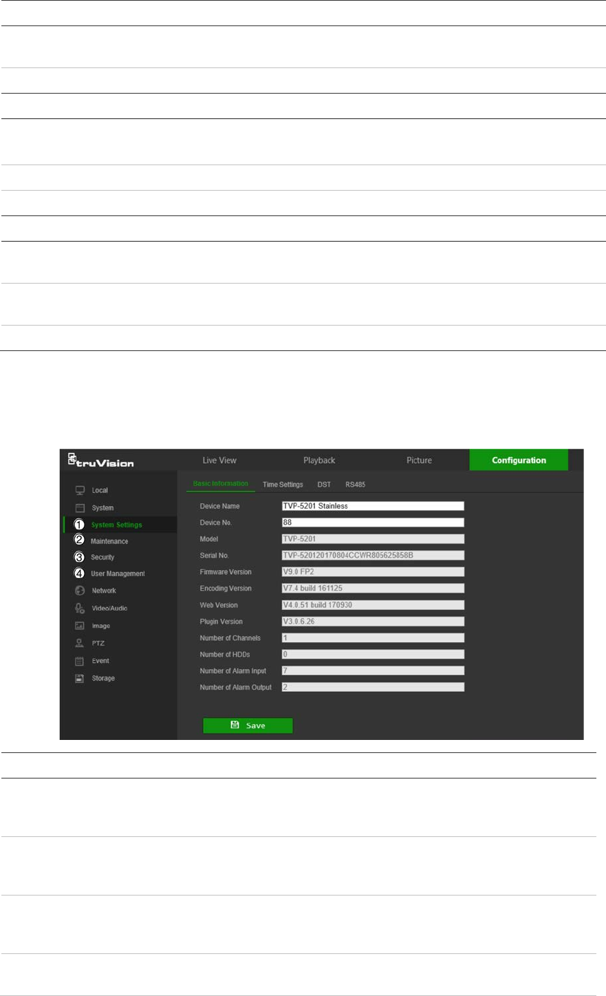
System
Use the System window to configure basic device information, system time, users,
security settings, and other parameters such as upgrading the firmware.
System submenus Description
1.
System
settings Defines device basic information including
SN and the current firmware
version and time settings (see “System time” on page 11). Also
contains camera hardware options (see “RS485” on page 12).
2.
Maintenance
Perform functions such as device reboot, set to default, export and
import configuration files, and firmware upgrade. Also contains an
exportable event log list. See “Maintenance” on page 61.
3.
Security
Defines who can use the camera, their passwords and access
privileges, RTSP authentication, IP address filter, and login lock. See
“Security” on page 59.
4.
User
management
Add or delete users and see which users are currently online. See
“User management” on page 56.
8 TruVision Stainless Steel PTZ Camera Configuration Manual
Network
Use the Network window to define basic and advanced network settings.
Network submenus Description
1.
Basic settings
Defines TCP/IP, DDNS, PPPoE, Port, and NAT settings (see “Basic
settings” on page 13).
2.
Advanced
settings
Defines SNMP, FTP, Email, HTTPS, QoS, and 802.1x settings (see
“Advanced settings” on page 16).
Video/Audio
Use the Video/Audio window to define recording parameters for video, audio, region of
interest (ROI), and display information on stream.
Image
Use the Image window to define the image display settings, OSD settings, overlay text,
and image parameters switch. See “Image” on page 23 for further information on setup.
PTZ
Use the PTZ window to move the lens to the required position using the PTZ panel, and
to define PTZ position settings, scheduled tasks, and privacy masks. See “PTZ
parameters” on page 28.
Event
Use the Event window to set up alarms by defining area settings, arming schedules,
and linkage methods.
TruVision Stainless Steel PTZ Camera Configuration Manual 9
Event submenus Description
1.
Basic
event Defines motion detection, video tampering, video loss, alarm
input/output, and exception alarm.
2.
Smart
event Defines intrusion, audio exception, face, region entrance/exit, and line
crossing detection.
Storage
Use the storage window to define recording schedule, storage management, network
attached storage (NAS) configuration, and snapshot configuration.
10 TruVision Stainless Steel PTZ Camera Configuration Manual
Storage submenus Description
1.
Schedule
settings
Configure recording settings and snapshot captures for all available
event types on a daily basis.
2.
S
torage
management
Manage hard drive storage space by file type and configure NAS
drives.
System time
Network Time Protocol (NTP) is a protocol for synchronizing the clocks of network
devices, such as IP cameras and computers. Connecting network devices to a
dedicated NTP time server ensures that they are all synchronized.
To define the system time and date:
1. From the menu toolbar, click Configuration > System > System Settings > Time
Settings.
2. From the Time Zone drop-down list, select the time zone that corresponds to the
camera’s location.
3. Select one of the following options for setting the time and date:
Synchronize with an NTP server: Select the NTP radio button and type the
required information in the Server Address and NTP Port boxes. The time interval
can be set from 1 to 10080 minutes.
—or—
Set manually: Select the Manual Time Sync radio button and then click to set
the system time from the pop-up calendar.
Note: Select the Sync with computer time checkbox to synchronize the time of the
camera with the time of the computer.
4. Click Save to save changes.
5. Click the DST tab and then select Enable DST to enable the DST (Daylight Savings
Time) function, and set the date of the DST period.
TruVision Stainless Steel PTZ Camera Configuration Manual 11
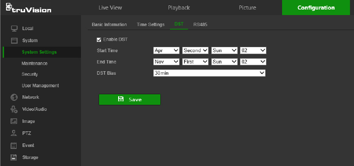
6. Set the date and time differential of the DST period using the Start Time, End
Time, and DST Bias drop-down lists.
7. Click Save to save changes.
RS485
The RS-485 serial port is used to control the PTZ of the camera or connect to light and
wiper devices. Configuration of these parameters should be done before you connect to
any devices.
To set up RS-485 settings:
1. From the menu toolbar, click Configuration > System > System Settings >
RS485.
2. Select the RS-485 port parameters.
Note: The Baud Rate, PTZ Protocol, and PTZ Address parameters should be
exactly the same as the PTZ camera parameters.
3. Click Save to save changes.
12 TruVision Stainless Steel PTZ Camera Configuration Manual
Network settings
Accessing the camera through a network requires the definition of certain network
settings. Use the Network menu to define these settings.
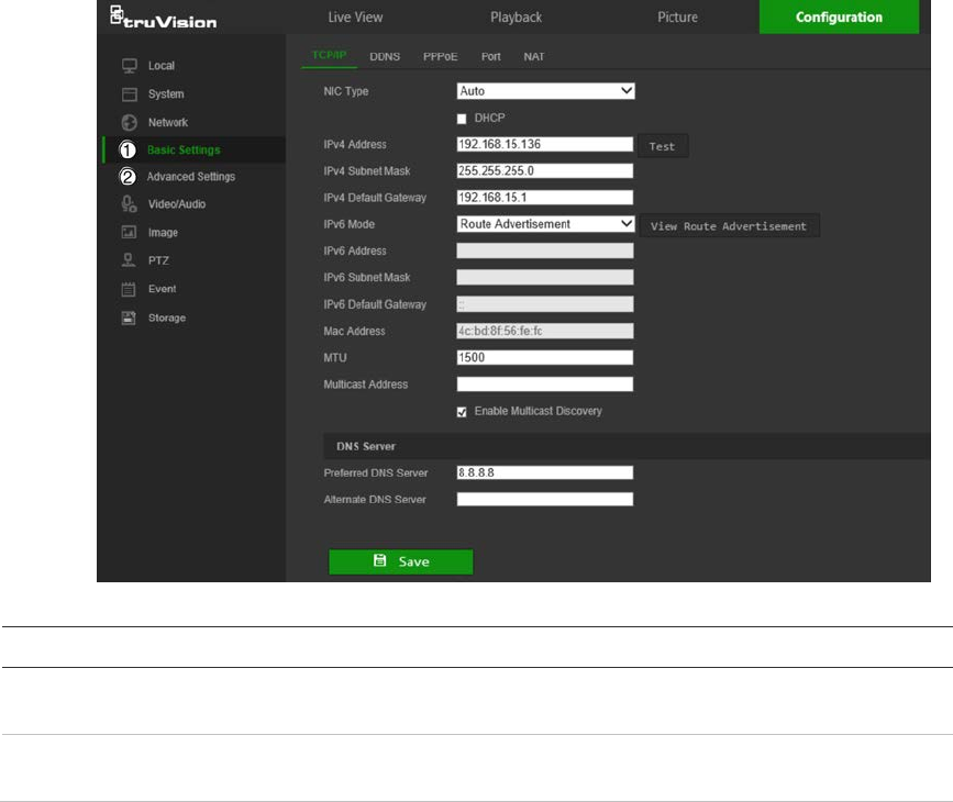
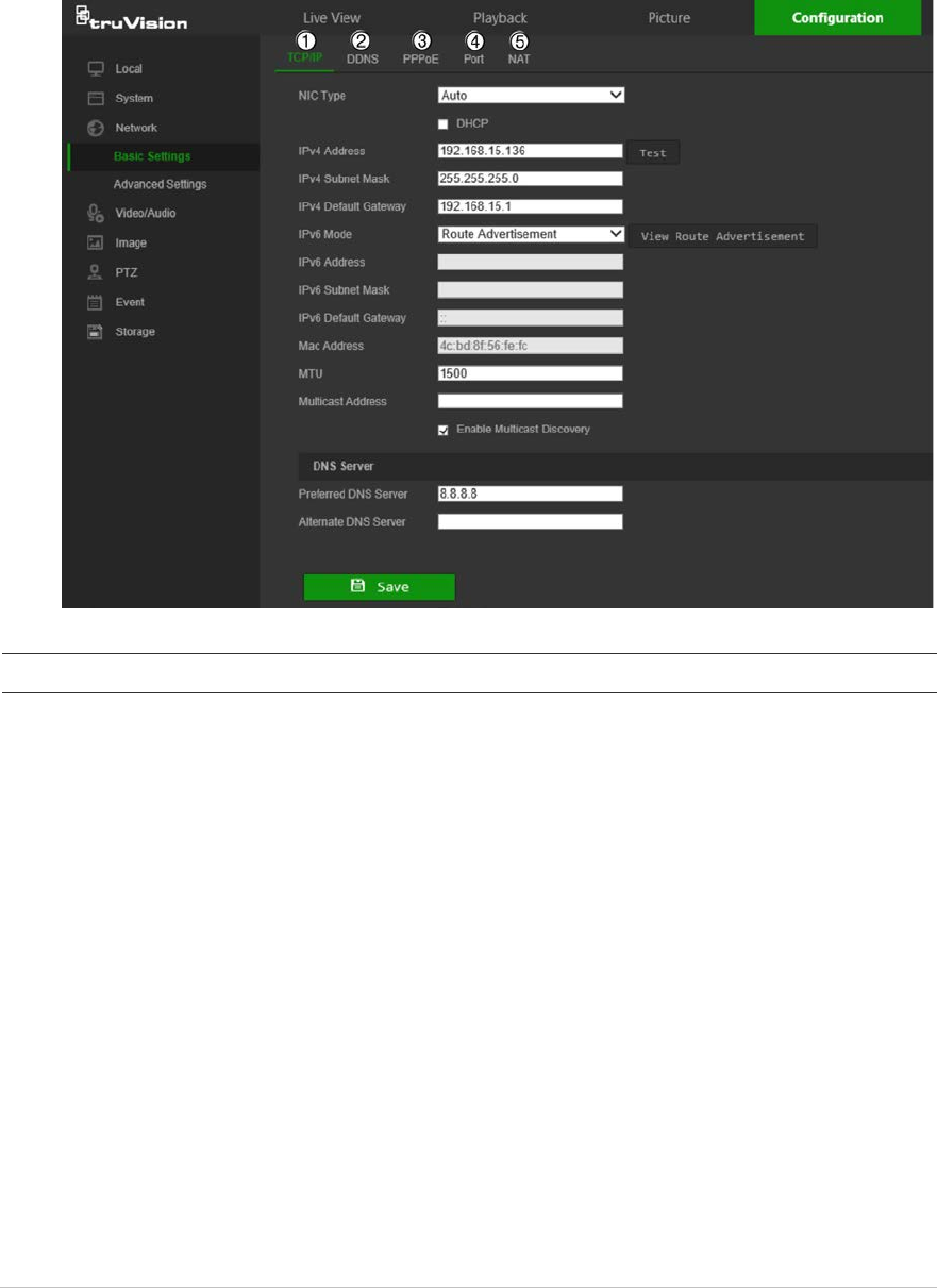
Basic settings
Menu tabs Description
1.
TCP/IP
NIC Type: Select the NIC type from the drop-down list. Default is Auto.
Other options include 10M Half-dup, 10M Full-dup, 100M Half-dup, and
100M Full-dup.
DHCP: Select DHCP to automatically obtain an IP address and other
network settings from that server.
IPv4 Address: If necessary, type in the IPv4 address of the camera.
IPv4 Subnet Mask: If necessary, type in the IPv4 subnet mask.
IPv4 Default Gateway: If necessary, type in
the IPv4 gateway IP address.
IPv6 Mode: Select Manual, DHCP, or Router Advertisement from the
drop-down list.
IPv6 Address: Type in the IPv6 address of the camera.
IPv6 Subnet Mask: Type in the IPv6 subnet mask.
IPv6 Default Gateway: Type in the IPv6 gateway IP address.
Mac Address: If necessary, type in the MAC address of the devices.
MTU: Type in the valid value range of MTU. Default is 1500.
Multicast Address: Enter a D-class IP address between 224.0.0.0 to
239.255.255.255. Only specify this option if using the multicast function.
Some routers prohibit the use of multicast function in case of a network
storm.
Enable Multicast Discovery: Enables the automatic detection of the
TruVision Stainless Steel PTZ Camera Configuration Manual 13

Menu tabs Description
online network camera via private multicast protocol in the LAN.
DNS server: Specifies the DNS server for the network.
See page 14 for setup information.
2.
DDNS
DDNS is a service that maps Internet domain names to IP addresses. It is
designed to support dynamic IP addresses, such as those assigned by a
DHCP server. DDNS permits remote connection to the camera’s network;
however the router serving that network must be configured properly for
remote access.
Make a selection from the DDNS Type drop-down list (IPServer,
DynDNS, ezDDNS, or NO-IP).
DynDNS (Dynamic DNS): Manually create a host name. A user account
must first be created using the DynDNS.org hosting web site.
ezDDNS: Activate the DDNS auto-detection function to set up a dynamic
IP address. The server is set up to assign an available host name to the
recorder.
IPServer: Type in the address, host name, and user name for the IP
Server.
See page 15 for setup information.
3.
PPPoE
Retrieves a dynamic IP address. See page 15 for setup information.
4.
Port
HTTP Port: The HTTP port is used for remote internet browser access.
Enter the port used for the IE browser. Default value is 80.
RTSP Port: RTSP (Real Time Streaming Protocol) is a network control
protocol designed for use in entertainment and communications systems
to control streaming media servers. Enter the RTSP port value. The
default port number is 554.
HTTPS Port: HTTPS (Hyper Text Transfer Protocol Secure) allows video
to be securely viewed when using a browser. Enter the HTTPS port,
value. The default port number is 443.
Server Port: This is used for remote client software access. Enter the
server port value. The default port number is 8000.
Alarm Host IP: Specifies the IP address of the alarm host.
Alarm Host Port: Specifies the port of the alarm host.
See page 15 for setup information.
5.
NAT
A NAT (Network Address Translation) is used for network connection.
Select Auto or Manual from the Port Mapping Mode drop-down list. See
page 16 for setup information.
To define the TCP/IP parameters:
1. From the menu toolbar, click Configuration > Network > Basic Settings > TCP/IP.
2. Configure the NIC settings, including the NIC Type, IPv4 settings, IPv6 settings,
MTU, and Multicast Address.
3. If a DHCP server is available, select the DHCP checkbox.
4. If the DNS server settings are required for some applications (e.g., sending email),
configure the Preferred DNS Server or Alternate DNS Server.
5. Click Save to save changes.
Note: Click the Wlan tab to configure the Wlan settings.
14 TruVision Stainless Steel PTZ Camera Configuration Manual
To define the DDNS parameters:
1. From the menu toolbar, click Configuration > Network > Basic Settings > DDNS.
2. Select the Enable DDNS check box to enable this feature.
3. Select DDNS Type:
• DynDNS: Enter the DNSS server address, members.ddns.org, which is used to
notify DDNS about changes to the IP address, the host name for the camera, the
port number (443 (HTTPS)), and the user name and password used to log into
the DDNS account. The domain name displayed under “Host Name” is the one
created on the DynDNS web site.
• ezDDNS: Type the required host name in the Host Name box. The default host
name is the utc-serial number. The default server address is www.tvr-ddns.net,
which cannot be changed. Click Get URL to register generate a URL that, when
copied and pasted into a browser, generates an IP address for the camera for
remote access.
Note: The camera’s network router must be configured for remote access.
• IPServer: Type the address of the IP Server.
• NO-IP: Type www.noip.com into the Server Address box and create a domain
name.
4. Click Save to save changes.
To define the PPPoE parameters:
1. From the menu toolbar, click Configuration > Network > Basic Settings > PPPoE.
2. Check Enable PPPoE to enable this feature.
3. Enter User Name, Password, and Confirm password for PPPoE access.
4. Click Save to save changes.
To define the port parameters:
1. From the menu toolbar, click Configuration > Network > Basic Settings > Port.
2. Set the HTTP port, RTSP port, HTTPS port and Server port of the camera.
HTTP Port: The default port number is 80, and it can be changed to any port No.
which is not occupied.
RTSP Port: The default port number is 554. It can be changed to any port number
in the range from 1 to 65535.
HTTPS Port: The default port number is 443. It can be changed to any port number
that is not occupied.
Server Port: The default server port number is 8000. It can be changed to any port
number in the range from 2000 to 65535.
3. Type the IP address and port to upload the alarm information to the remote alarm
host. Also, select the Notify Alarm Recipient option in the Normal Linkage of each
event page.
TruVision Stainless Steel PTZ Camera Configuration Manual 15
4. Click Save to save changes.
To set up the NAT parameters:
Network Address Translation (NAT) permits automatic communication with a network
router.
1. Click Configuration > Network > Basic Settings > NAT.
2. Select the Enable UPnP check box to enable the NAT function.
3. Select Auto or Manual from the Port Mapping Mode drop-down list. When Manual
is selected, click on an external port number to change it by typing in a new port
number.
Note: If a non-default external port number is assigned, the network router settings
must be configured accordingly.
4. Click Save to save changes.
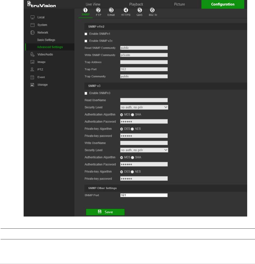
Advanced settings
Menu tabs Description
1.
SNMP
SNMP is a protocol for managing devices on networks. Enable SNMP to
get camera status and parameter related information. See page 17 for
setup information.
16 TruVision Stainless Steel PTZ Camera Configuration Manual

Menu tabs Description
2
FTP
Enter the FTP address and folder to which camera snapshots can be
uploaded. See page 17 for setup information.
3.
Email
Enter the email address to which messages are sent when an alarm
occurs. See page 18 for setup information.
4.
HTTPS
Specifies authentication of the website and its associated web server,
which protects against Man-in-the-middle attacks.
5.
QoS
QoS (Quality of Service) can help solve network delay and congestion by
configuring the priority of data sending. See page 20 for setup information.
6.
802.1x
When the feature is enabled, the camera data is secured and user
authentication is needed when connecting the camera to the network.
See
page 20 for setup information.
To define the SNMP parameters:
1. From the menu toolbar, click Configuration > Network > Advanced Settings >
SNMP.
2. Select the corresponding version of SNMP: v1, v2c or v3.
3. Configure the SNMP settings. The configuration of the SNMP software should be
the same as the settings you configure here.
4. Click Save to save changes.
Note: Before configuring SNMP, test your SNMP monitoring software and attempt
to receive the camera information via the SNMP port. By setting the Trap Address,
the camera can send the alarm event and exception messages to the SNMP
monitoring software. The SNMP version you select should be the same as that
supported by the SNMP software.
To define the FTP parameters:
1. From the menu toolbar, click Configuration > Network > Advanced Settings >
FTP.
2. Configure the FTP settings, including the Server Address, Port, User Name,
Password, Directory Structure, and upload type.
Anonymous: Select this check box to enable anonymous access to the FTP server.
Directory Structure: Select the Save in the root directory, Save in the parent
directory, or Save in the child directory. When the parent directory is selected,
select Use Device Name, Use Device Number, Use Device IP, or Custom (type in
a directory name) for the name of the parent directory. If Save in the child
directory is selected, select Use Camera Name, Use Camera Number, or
Custom as the name of the child directory.
Snapshot Filing Interval: Select a number of days to specify how many days of
snapshots should be stored in a single folder. All snapshots are saved to a single
folder in default mode (OFF).
Snapshot Name: Select Custom Prefix to change the default snapshot name
prefix. Invalid characters for the custom prefix are as follows: / \ : * ? ‘ “ < > | %.
TruVision Stainless Steel PTZ Camera Configuration Manual 17
Upload Snapshot: Select this check box to enable the uploading of snapshots to an
FTP server.
Test: Click Test to test the FTP parameters.
3. Click Save to save changes.
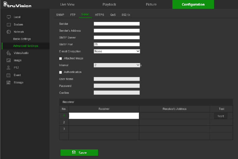
To set up the email parameters:
1. From the menu toolbar, click Configuration > Network > Advanced Settings >
Email.
2. Configure the following settings:
Sender: The name of the email sender.
Sender’s Address: The email address of the sender.
SMTP Server: The SMTP Server, IP address, or host name.
SMTP Port: The SMTP port. The default is 25.
Email Encryption: Select None, SSL, or TLS. If the Enable STARTTLS check box
is not selected after selecting SSL or TLS, emails are sent after encryption via SSL
or TLS. The SMTP port should be set as 465 for this encryption method. After
selecting SSL or TLS and then selecting Enable STARTTLS, emails are sent after
encryption via STARTTLS, and the SMTP port should be set as 25.
Note: When using STARTTLS, ensure that the protocol is supported by the email
server. If the Enable STARTTLS check box is selected when the protocol is not
supported by the email server, email will not be encrypted.
Attached Snapshot: Select the Attached Snapshot check box to send emails with
attached alarm images.
Interval: This is the time between two actions of sending attached snapshots.
18 TruVision Stainless Steel PTZ Camera Configuration Manual
Authentication: If the email server requires authentication, select this check box to
use authentication to log in to this server. Enter the login user name and password.
User Name: The user name to log in to the server where the images are uploaded.
Password: Enter the password.
Confirm: Confirm the password.
Receiver: Click inside the Receiver table to type in receiver names and email
addresses. Row 1 shows the first user to be notified, Row 2 shows the second user
to be notified, and so on.
3. Click Test to test the email parameters for each receiver.
4. Click Save to save changes.
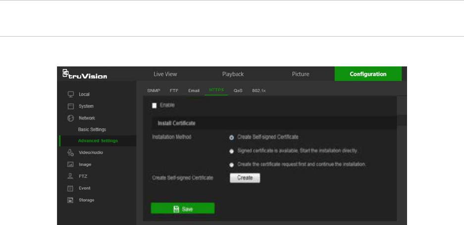
To set up the HTTPS parameters:
A valid certificate must be installed to use a secure HTTPS connection for accessing
the user interface.
Caution: Removing and installing certificates is only recommended for advanced
users.
1. Click Configuration > Network > Advanced Settings > HTTPS.
2. Deselect Enable and click Save to remove the default certificate.
3. To create a self-signed certificate:
Select the Create Self-signed Certificate radio button and then click Create. Enter
the country, host name/IP, validity, and the other information requested.
—or—
To create a certificate request:
Select the Signed Certificate is available, Start the installation directly radio
button and then click Create. Upload the certificate to the device.
—or—
To create an authorized certificate:
Select the Create the certificate request first and continue the installation as
radio button and then click Create. Fill in the required information in the popup
TruVision Stainless Steel PTZ Camera Configuration Manual 19
window. Download the certificate request and submit it to the trusted certificate
authority (such as Symantec or RSA) for signature. After receiving the signed valid
certificate, upload the certificate to the device.
4. Click OK to save the settings.
To define the QoS parameters:
1. From the menu toolbar, click Configuration > Network > Advanced Settings >
QoS.
2. Configure the QoS settings, including Video/Audio DSCP, Event/Alarm DSCP,
and Management DSCP. The valid value range of the DSCP is 0-63. The higher
the differentiated services code point (DSCP) value, the higher the priority of the
service.
3. Click Save to save changes.
To define the 802.1x parameters:
1. From the menu toolbar, click Configuration > Network > 802.1X.
2. Check Enable IEEE 802.1X to enable the feature.
3. Configure the 802.1X settings, including EAPOL version, user name, and password.
The EAPOL version must be identical with that of the router or the switch.
4. Click Save to save changes.
Note: The switch or router to which the camera is connected must support the IEEE
802.1X standard, and a server must be configured. Please apply and register a user
name and password for 802.1X in the server.
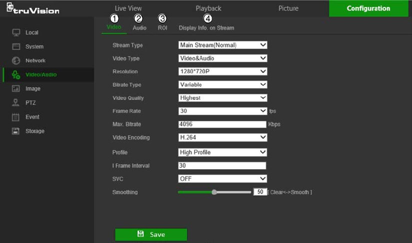
Video/Audio
Adjust the video and audio recording parameters to obtain the required picture quality
and file size.
20 TruVision Stainless Steel PTZ Camera Configuration Manual

Tab Parameter descriptions
1.
Video
Stream Type: Specifies the streaming method used.
Options include: Main Stream (Normal), Sub Stream and Third
stream.
Video Type: Specifies the stream type for recording.
Select Video Stream to record video stream only. Select
Video&Audio to record both video and audio streams.
Note: Video&Audio is only available for those camera models that
support audio.
Resolution: Specifies the recording resolution. A higher image
resolution provides a higher image quality but also requires a higher bit
rate. The resolution options listed depend on the type of camera and if
main or sub stream is being used.
Note: Resolutions can vary depending on the camera model.
Bitrate Type: Specifies whether variable or fixed bit rate is used.
Variable produces higher quality results suitable for video downloads
and streaming.
Video Quality: Specifies the quality level of the image. It can be set
when variable bit rate is selected. Options include: Lowest, Lower,
Medium, Higher and Highest.
Frame Rate: Specifies the frame rate for the selected resolution.
The frame rate is the number of video frames that are shown or sent
per second.
Note: The maximum frame rate depends on the camera model and
selected resolution. Refer to the camera’s specifications.
Max Bitrate: Specifies the maximum allowed bit rate. To maintain high
quality image resolution, a high bit rate must also be selected.
Video Encoding: Specifies the video encoding used.
Profile: Different profile options indicate different tools and
technologies used in compression. Options include: High Profile,
Main
Profile, and Basic Profile.
SVC: Select OFF or ON to disable/enable the SVC function. Select
Auto and the device will automatically extract frames from the original
video when the network bandwidth is insufficient.
I-frame Interval: A video compression method. We strongly
recommended not changing the default value of 50.
Smoothing: Adjust the smoothness of the stream.
2.
Audio
Audio Encoding: G.722.1, G.711ulaw, G.711alaw, MP2L2, G.726,
and PCM encoding standards are selectable.
Audio Input: MicIn is selectable for the connected microphone.
Input Volume: Specifies the volume from 0 to 100.
Environmental Noise Filter: Set as OFF or ON to filter environmental
.
noise.
3.
ROI
Define a region of interest (ROI) within the camera view. Assigns more
encoding resources to an ROI (background information is less focused
when network performance is less than optimal).
TruVision Stainless Steel PTZ Camera Configuration Manual 21

Tab Parameter descriptions
4.
D
isplay Info. On
Stream
When Dual-VCA mode is enabled, the camera sends video analytics
results (metadata) to an NVR or other platforms to generate a VCA
alarm.
To configure ROI settings:
1. From the menu toolbar, click Configuration > Video/Audio > ROI.
2. Click Draw Area to draw the region of interest on the image. Up to four regions can
be drawn.
3. Select the stream type from the Stream Type drop-down list to set the ROI
encoding.
4. Select Enable under Fixed Region to manually configure the area.
Region No.: Select the region.
ROI Level: Choose the image quality enhancing level.
Region Name: Type the required region name.
5. Select Enable Face Tracking and/or Enable Target Tracking under Dynamic
Region for face and target tracking. The ROI will change, depending upon where
faces or targets are detected in the scene.
22 TruVision Stainless Steel PTZ Camera Configuration Manual
ROI Level: Choose the image quality enhancing level.
6. Click Save to save changes.
Dual-VCA (Video Content Analysis)
When Dual-VCA mode is enabled, the camera sends video analytics results (metadata)
to an NVR or other platforms to generate a VCA alarm.
For example, with an Interlogix NVR (please check Interlogix website for the latest NVR
models supporting this feature), a virtual line can be drawn in the NVR playback
window, and the objects or people crossing this virtual line can be searched.
Note: Only cross line and intrusion detection can support dual-VCA mode.
To define Dual-VCA parameters:
1. From the menu toolbar, click Configuration > Video/Audio > Display Info. On
Stream.
2. Select the Enable Dual-VCA check box.
3. Click Save to save changes.
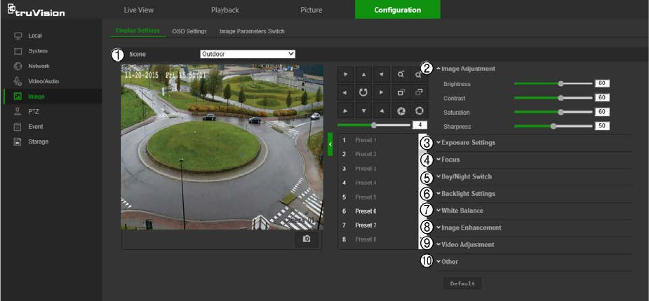
Image
The camera image may need to be adjusted to obtain the best image quality depending
on the camera model or location background. Adjust the brightness, contrast, saturation,
hue, and sharpness of the video image using the Image menu.
Use this menu to also adjust camera behavior parameters such as exposure time, iris
mode, video standard, day/night mode, image flip, WDR, digital noise reduction, white
balance, and scene mode (indoor/outdoor, etc.). Use the PTZ control buttons in the
PTZ panel to point the camera at a specific area, or select a predefined preset position.
TruVision Stainless Steel PTZ Camera Configuration Manual 23

Parameter Description
1.
Scene
Indoor, Outdoor, Day,
Night, Morning, Nightfall,
Street, Low Illumination,
Custom1, Custom2
Choose the scene according to the current environment.
Note: The scene must be set to Outdoor to enable local output.
2.
Image Adjustment
Brightness
, Contrast,
S
aturation, Sharpness Modifies the different elements of picture quality by adjusting the
position of the values for each parameter.
3.
Exposure Settings
Exposure Mode
The Exposure Mode can be set to Auto, Iris Priority, Shutter Priority,
and
Manual.
Auto: The iris, shutter and gain values will be adjusted automatically
according to the brightness of the environment.
Iris Priority: The value of iris needs to be adjusted manually. The
shutter and gain values will be adjusted automatically according to the
brightness of the environment.
Shutter Priority: The value of shutter needs to be adjusted manually.
The iris and gain values will be adjusted automatically according to the
brightness of the environment.
Manual: You can adjust the values of Gain, Shutter, and Iris manually.
Limit
Gain This feature is used to adjust the image
gain. The value ranges from 0 to
100.
Slow Shutter
The shutter speed controls the length of time that the aperture is open to
let light into the camera through the lens. A slow shutter speed means it
is open for longer. Select On or Off. Default is Off.
Slow Shutter Level
If Slow Shutter is enabled, use this feature to adjust the shutter speed.
Default value is Slow Shutter*2.
4.
Focus Settings
F
ocus Mode If the camera supports an electronic lens, you can set the focus mode
as Manual, Auto or Semi-auto. Default is Semi-auto.
Auto: The camera focus is adjusted automatically.
Manual: You can control the lens by adjusting the zoom, focus, lens
initialization, and auxiliary focus via the PTZ control interface. Default is
Manual.
Semi-auto: The camera focuses automatically only once after panning,
tilting and zooming.
Minimum Focus
Distance This function is used to set the limit of the minimum focus distance. The
value can be set to 10 cm, 50 cm, 1.5 m, 3 m, 6 m, 10 m, or 20 m.
Default is 6 m.
5.
Backlight Settings
BLC Area
If you focus on an object against strong backlight, the object will be too
dark to be seen clearly. BLC compensates light to the object in the front
to make it clear. Off, Up, Down, Left, Right, and Center are selectable.
Default is Off.
WDR
When enabled, this feature (wide dynamic range) allows you to see
details of objects in shadows or details of objects in bright areas of
frames that have high contrast between light and dark areas. Default is
24 TruVision Stainless Steel PTZ Camera Configuration Manual
Parameter Description
Off.
Wide Dynamic Level
If WDR is enabled, set the wide dynamic level between 0 and 100.
HLC
Highlight compensation (HLC) is a camera technology that detects if
there are any strong spots of light and compensates for the area as
needed to produce clearer images. Used to read, for example, car
number-plates in streets or parking lots at night. Default is Off.
6.
Day/Night Switch
Day/Night Switch
Defines whether the camera is in day or night mode. The day (color)
option could be used, for example, if the camera is located indoors
where light levels are always good. Select one of the options (Default is
Auto):
Day: Camera is always in day mode.
Night: Camera is always in night mode.
Auto: The camera automatically detects which mode to use.
Schedule: Select the start and end times for day mode
7.
White Balance
White Balance
White balance (WB) tells the camera what the color white looks like.
Based on this information, the camera will then continue to display all
colors correctly even when the color temperature of the scene changes
such as from daylight to fluorescent lighting, for example. Select one of
the options (Default is Auto):
MWB: Manually adjust the color temperature to meet your own
requirements.
Outdoor: Apply for outdoor environments.
Indoor: Apply for indoor environments.
Fluorescent Lamp: Apply for scene where there are fluorescent lamps
installed near the camera.
Sodium Lamp: Apply for scene where there are incandescent lamps
near the camera.
Auto-Track: White balance is continuously being adjusted in real-time
according to the color temperature of the scene illumination.
Auto: White balance is determined automatically.
8.
Image Enhancement
Digital Noise Reduction
Digital noise reduction (DNR) reduces noise, especially in low light
conditions, to improve image performance. Select one of the options
(Default is Normal Mode):
Normal Mode: Standard DNR.
Expert Mode: Set up the Space DNR level and the Time DNR level.
Space DNR level is used to reduce static noise, but if you configure a
higher value, the image may be not clear. Time DNR level is used to
reduce dynamic noise. If you configure a higher value, the moving object
may have an obvious shadow.
Off: Disable the function.
Noise Reduction Level
Only available when DNR is set to Normal Mode. Set the level of noise
reduction in the Normal Mode. Higher value has a stronger noise
reduction. Default is 50.
Defog
Mode You can enable the defog function when the environment is foggy and
the image is misty. It enhances the subtle details so that the image
appears clearer. Default is Off.
TruVision Stainless Steel PTZ Camera Configuration Manual 25
Parameter Description
EIS
Electrical Image Stabilizer (EIS) reduces the effects of vibration in a
video. Default is Off.
9.
Video Adjustment
Mirror
It mirrors the image so you can see it inversed. Center, or OFF are
selectable. Default is OFF.
Video Standard
50 Hz and 60 Hz are selectable. Select the standard according to the
different video standards; normally 50 Hz for PAL standard and 60
Hz for
NTSC standard. Default is 60 Hz.
Capture Mode
Set the desired frame rate to meet the different demands of field of view
and resolution. A higher frame rate may be required in a location with a
lot of movement (such as a money depot). Default is Off.
10.
Other
Lens Initialization
Enable the option so that the lens operates the movements for
initialization. Default is Disabled.
Zoom Limit
Set the limit of the maximum value of zooming. Default is 23.
Local Output
Select ON or OFF to enable or disable the BNC output. Default is ON.
Note: Click the Default button to return all the image settings to default values.
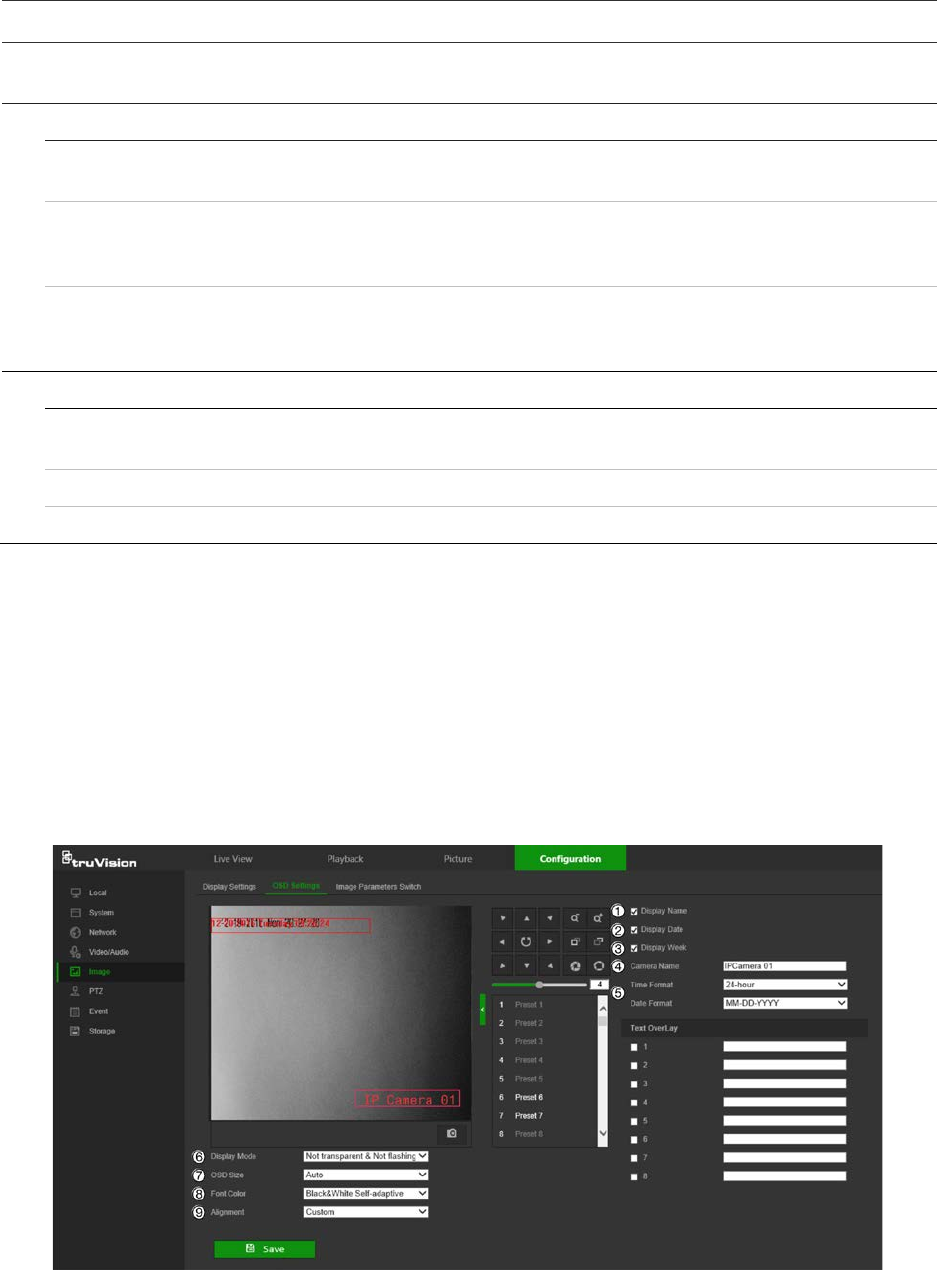
OSD (On Screen Display) Settings
In addition to the camera name, the camera also displays the system date and time on
the screen. How the text appears on screen can also be defined.
To position the on-screen date/time and name:
1. From the menu toolbar, click Configuration > Image > OSD Settings.
2. Select the Display Name check box (1) to display the on-screen camera name.
3. Select the Display Date check box (2) to display the date/time on screen.
4. Select the Display Week check box (3) to include the day of the week in the on-
screen display.
26 TruVision Stainless Steel PTZ Camera Configuration Manual
5. In the Camera Name box (4), type the camera name.
6. Select the time and date formats from the Time format and Date format drop-down
lists (5).
7. Select a display mode for the camera from the Display Mode drop-down list (6).
Display modes include:
• Transparent & Not flashing. The image appears through the text.
• Transparent & Flashing. The image appears through the text. The text flashes
on and off.
• Not transparent & Not flashing. The image is behind the text. This is the
default setting.
• Not transparent & Flashing. The image is behind the text. The text flashes on
and off.
8. Select the OSD size (7). Pixel display options include Auto, 16*16, 32*32, 48*48,
and 64*64.
9. Select the OSD font color (8). Options include Black&White Self-adaptive and
Custom. Use the color picker to assign a font color after selecting Custom.
10. Select the alignment (9). Options include Align Right, Align Left, and Custom.
11. Click Save to save changes.
Note: When the display mode is set as transparent, the text varies according the
background. With some backgrounds, the text may not be easy to read.
Text overlay
Add up to four lines of on-screen text in the Text Overlay section. This option can be
used to display emergency contact details and/or other information. Each text line can
be positioned anywhere on the screen.
To add on-screen text:
1. From the menu toolbar, click Configuration > Image > OSD Settings.
2. In the Text Overlay section, select check box 1.
3. Type the text in the text box.
4. Use the mouse to click and drag the red text in the live view window to adjust the
text overlay position.
5. Repeat steps 2 to 4 for each extra line of text, selecting the next string number.
Note: Remove overlay text by deselecting its corresponding check box.
6. Click Save to save changes.
Image parameters switch
Link to Preset or Scheduled-Switch can be configured in this window.
Link to Preset: Set the time period and linked scene for the preset and check the
corresponding checkbox to go to the linked scene in the configured time period.
TruVision Stainless Steel PTZ Camera Configuration Manual 27

Scheduled-Switch: Set the time period and linked scene and it will go to the linked
scene in the configured time period when the corresponding check box is selected.
To configure the image parameters switch:
1. From the menu toolbar, click Configuration > Image > Image Parameters Switch.
2. Select the Link to Preset or Scheduled-Switch check box. Only one of these
functions can be selected.
3. If selecting Link to Preset, select a number from the Preset drop-down list.
4. Select up to four time period check boxes, set the time period, and make a selection
from the Linked Scene drop-down list for each time period selected (Indoor,
Outdoor, Day, Night, Morning, Nightfall, Street, Low Illumination, Custom1,
Custom2).
5. Click Save to save changes.
PTZ parameters
The following sections explain how to configure the different PTZ parameters.
PTZ home position
The initial position is the PTZ home coordinates. It can be the factory default position or
you can customize the initial position to your own requirements.
To set the initial position:
1. From the menu toolbar, click Configuration > PTZ > Initial Position.
2. Click the PTZ control buttons to find a position as the initial position of the camera.
You can also call a defined preset and set it as the initial position.
3. Click Set to save the position.
To call and delete the initial position:
• Click Call to call the initial position.
• Click Clear to delete the initial position and restore the factory default initial position.
28 TruVision Stainless Steel PTZ Camera Configuration Manual

Basic PTZ parameters
You can configure the PTZ parameters, such as proportional pan, preset freezing,
preset speed, keyboard control speed, auto scan speed, and PTZ OSD.
To define basic PTZ parameters:
1. From the menu toolbar, click Configuration > PTZ > Basic Settings.
2. Configure the following settings:
1. Basic:
Proportional Pan If you enable this function, the pan/tilt speeds change according to
the amount of zoom. When there is a large amount of zoom, the
pan/tilt speed will be slower for keeping the image from moving too
fast on the live view image.
Preset Freezing This function enables live view to switch directly from one scene
defined by a preset to another, without showing the middle areas
between the presets. This helps ensure surveillance efficiency. It
can also reduce the use of bandwidth in a digital network system.
Note: Preset freezing function is invalid when calling up a pattern.
Preset Speed Set the speed of a defined preset from 1 to 8.
Manual Control Speed Set the manual control speed by selecting one of the following
options (Default is Auto):
Compatible: The control speed is same as the Keyboard Control
Speed.
Pedestrian: Choose this option when monitoring pedestrians.
Non-motor Vehicle: Choose this option when monitoring non-
motor vehicles.
Motor Vehicle: Choose this option when monitoring motor vehicles.
Auto: This is the recommended setting when the application scene
of the speed dome is complicated.
Keyboard Control Speed Define the speed of PTZ control by a keyboard as Low, Normal or
High. Default is Low.
TruVision Stainless Steel PTZ Camera Configuration Manual 29

Auto Scan Speed The camera provides five scan modes: auto scan, tilt scan, frame
scan, random scan and panorama scan. The scan speed can be
set from level 1 to 40. Default is 12.
Max. Tilt Angle You can set the maximum tilt angle of the lens. There are six
options: -5 to 90, -4 to 90, -3 to 90, -2 to 90, -1 to 90, 0 to 90.
Default is -1 to 90.
Zooming Speed You can vary the zooming speed. The zooming speed can be set
from level 1 to 3. Default is 3.
2. PTZ OSD:
Set the on-screen display duration of the PTZ status.
Zoom Status Set the OSD duration of zooming status as 2 seconds, 5 seconds,
10 seconds, Always Close, or Always Open. Default is 2s.
PT Status Set the azimuth angle display duration while panning and tilting as 2
seconds, 5 seconds, 10 seconds, Always Close, or Always Open.
Default is 2s.
Position Display Format Set the position display format to PT or Direction. Default is PT.
Preset Status Set the preset name display duration while calling the preset as 2
seconds, 5 seconds, 10 seconds, Always Close, or Always Open.
Default is 10s.
3. Power-off Memory: The dome resumes its previous PTZ status or actions after it
restarts from a power off. You can set the time point at which the
dome resumes its PTZ status. You can set it to resume at 30
seconds, 60 seconds, 300 seconds, or 600 seconds before power
off. Default is 30s.
3. Click Save to save changes.
Limit camera movement
The camera can be programmed to move only within a defined area. It can be limited in
how much it can move left/right and up/down. This can be useful when you do not want
an area, such as a neighboring building, to be included in the camera view.
To define the limit stop parameters:
1. From the menu toolbar, click Configuration > PTZ > Limit.
30 TruVision Stainless Steel PTZ Camera Configuration Manual
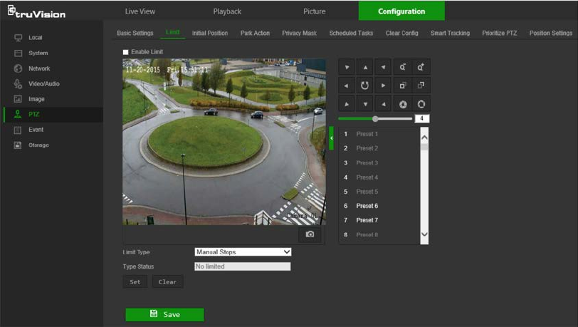
2. Click the Enable Limit checkbox to enable the limit function.
3. Click the Set button and use the PTZ control panel to set the limits of the camera
movement. You can also call up defined presets and set them as the limits of the
camera.
Click Clear to delete the set limits.
4. Select the limit type.
Manual Stops: When manual limit stops are set, you can operate the PTZ control
panel manually only within the restricted surveillance area.
Scan Stops: When scan limit stops are set, the random scan, frame scan, auto
scan, tilt scan, panorama scan are performed only within the restricted surveillance
area.
Note: The option Manual Stops has priority over Scan Stops. If these two
functions are set at the same time, only Manual Stops is enabled.
The status of the camera movement is displayed under Type Status as Not Limited
or Limited. The limit changes are saved automatically
5. Click Save to save changes.
Park actions
This is the action that will run automatically after the dwell time. A park action can be,
for example, a scan, preset, patrol, or a pattern.
Note: The Scheduled Tasks function (see page 31) has priority over the Park Action
function. If these two functions are set at the same time, only Scheduled Tasks is
enabled.
To define a park action:
1. From the menu toolbar, click Configuration > PTZ > Park Action.
TruVision Stainless Steel PTZ Camera Configuration Manual 31
2. Select the Park Action check box.
3. Set the Park Time, which is the inactivity time of the dome before it starts the park
action.
4. Make a selection from the Action Type drop-down list.
5. If Patrol, Pattern, or Preset is selected as the Action Type, a number must be also
be selected from the Action Type ID drop-down list.
6. Click Save to save changes.
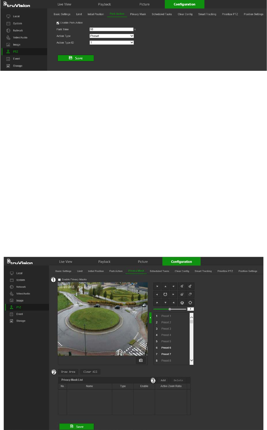
Privacy masks
Privacy masks let you conceal sensitive areas (such as neighboring windows) to protect
them from view on the monitor screen and in the recorded video. The masking appears
as a blank area on screen. You can create up to 24 privacy masks per camera.
Note: There may be a small difference in size of the privacy mask area depending on
whether local output or the web browser is used.
To add privacy mask area:
1. From the menu toolbar, click Configuration > PTZ > Privacy Mask.
32 TruVision Stainless Steel PTZ Camera Configuration Manual
2. Select Enable Privacy Masks (1).
3. Using the PTZ control buttons, point the camera at the desired area, or select a
predefined preset position, where you want to set the privacy mask.
4. Click the Draw Area button (2). Click and drag the mouse in the live video window to
draw the mask area.
5. Click Stop Drawing to finish drawing, or click Clear All to clear all of the areas you
set without saving them.
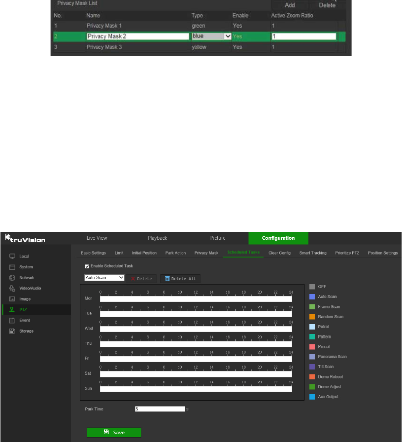
6. Click Add (3) to add the area. Enter its name, color, and active zoom ratio. Each
mask can be individually set.
Note: The active zoom ratio is the magnification level the camera will zoom into
when motion is detected.
7. Click Save to save changes.
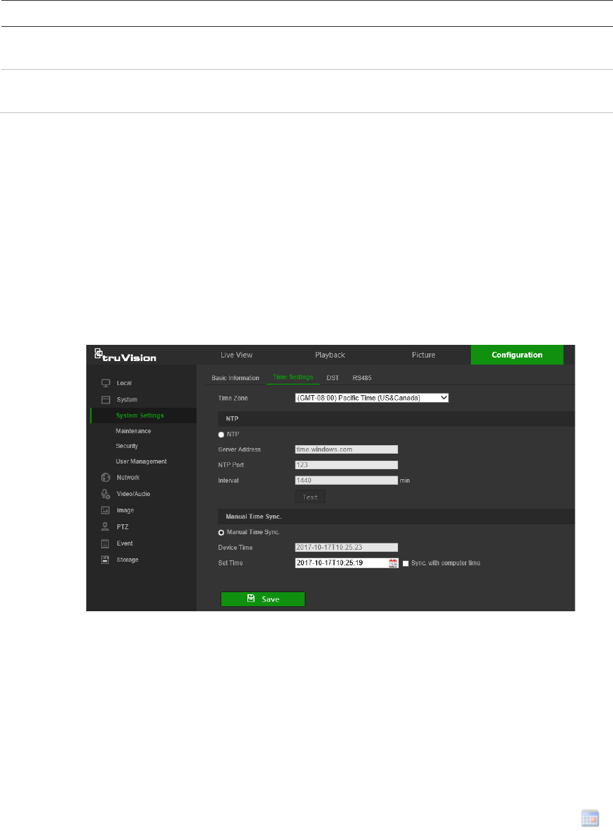
Scheduled tasks
You can configure the camera to perform a specific action automatically during a user-
defined time period.
To define a scheduled task:
1. From the menu toolbar, click Configuration > PTZ > Scheduled Tasks.
2. Select the Enable Scheduled Task check box.
3. Set the Park Time. You can set the park time in seconds (a period of inactivity)
before the camera starts the scheduled tasks.
4. Choose the task type from the drop-down list (see the list of color-coded tasks on
the right side of the window).
TruVision Stainless Steel PTZ Camera Configuration Manual 33
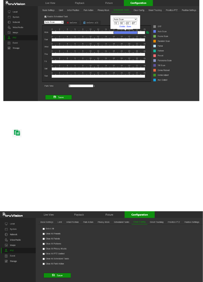
5. Click and drag along the time bars or click on a time bar to configure recording
schedule times and alarm/event types.
Note: All scheduled times are based on the 24-hour clock. Ensure that the correct
time zone and daylight saving time settings have been configured in Configuration
> System > System Settings.
6. Click to copy the schedule to other days by selecting the corresponding check
box next to the day.
7. Click Save to save changes.
Clear PTZ configurations
Use the PTZ configurations menu to clear all presets, patrols, patterns, privacy masks,
PTZ limits, scheduled tasks, and park actions.
To clear PTZ configurations:
1. From the menu toolbar, click Configuration > PTZ > Clear Config.
2. Select the check boxes for the options that need to be cleared.
3. Click Save to save changes.
Smart tracking
Smart tracking is used to track a moving object or person in a selected region.
34 TruVision Stainless Steel PTZ Camera Configuration Manual

To define smart tracking:
1. From the menu toolbar, click Configuration > PTZ > Smart Tracking.
2. Select the Enable Smart Tracking check box.
3. Using the PTZ control buttons, point the camera at the desired area, or select a
predefined preset position, where you want to set intelligent tracking.
4. Set the duration time. This is the time during which the camera follows the moving
object or person. You can select up to 300 seconds.
5. Set the zoom ratio (2). This is the zoom level used when you start to track the
person or object.
6. Click Save to save changes.
Prioritize PTZ
1. From the menu toolbar, click Configuration > PTZ > Prioritize PTZ.
2. Select Network or RS-485 from the Prioritize PTZ drop-down list.
3. Set the delay time by typing a value in the Delay field. The range is from 2-200
seconds.
4. Click Save to save changes.
Position settings
1. From the menu toolbar, click Configuration > PTZ > Position Settings.
2. Manually find the north position for the camera in Live View interface, and click Set
at North to set the north direction.
3. After the camera changes its direction, you can click Point to North and the camera
turns back to the north direction.
4. Manually set GPS information including longitude and latitude under GPS.
TruVision Stainless Steel PTZ Camera Configuration Manual 35
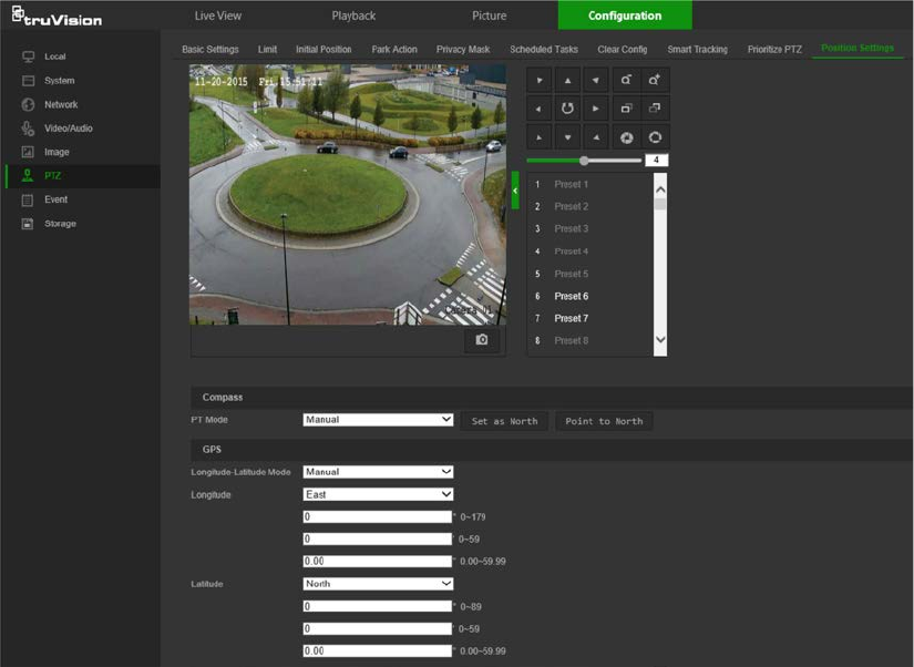
5. Click Save to save changes.
Basic event
Motion detection alarms
A motion detection alarm refers to an alarm triggered when the camera detects motion.
The motion alarm is only triggered if it occurs during a programmed time schedule.
Select the level of sensitivity to motion as well as the target size so that only objects
that could be of interest trigger a motion recording. For example, the motion recording
is triggered by the movement of a person but not that of a cat.
Define the area on-screen where the motion is detected, the level of sensitivity to
motion, the schedule when the camera is sensitive to detecting motion, as well as
which methods are used to produce a motion detection alarm.
Dynamic analysis for motion can also be enabled. When there is motion, the motion
area is indicated by green rectangles.
36 TruVision Stainless Steel PTZ Camera Configuration Manual
Defining a motion detection alarm requires the following tasks:
1. Area settings: Define the on-screen area that can trigger a motion detection alarm
and the detection sensitivity level.
2. Arming schedule: Define the schedule during which the system detects motion.
3. Linkage: Specify the method of response to the alarm (see below). Trigger
Recording must be selected to launch recordings to be stored on the SD card or in
NAS.
4. Normal and advanced configuration: Normal configuration permits setting the
sensitivity level of the motion detection. Advanced configuration provides more
control over how motion is detected. It permits setting the sensitivity level as well as
the percentage of the motion detection area that the object must occupy, selecting
day or night mode, and setting up eight differently configured defined areas.
5. Recording schedule: Define the schedule during which motion detection can be
recorded. See “Recording schedule” on page 50 for further information.
Note: All scheduled times are based on the 24-hour clock. Ensure that the correct
time zone and daylight saving time settings have been configured in Configuration
> System > System Settings.
Linkage methods
The linkage methods available are as follows:
TruVision Stainless Steel PTZ Camera Configuration Manual 37

Notify
Alarm Recipient Send an exception or alarm signal to the remote management
software when an event occurs.
Notify Surveillance Center
Triggers an audible warning locally (only applies to cameras
with an audio output).
Send
Email Sends an email to a specified address when there is a motion
detection alarm.
Note: Email settings must be configured before enabling this
option. See “To set up the email parameters” on page 18 for
further information. To send the event snapshot together with
the email, select the Attached Snapshot check box.
Upload
to Snapshot Capture a snapshot when an alarm is triggered and upload the
snapshot to NAS or an FTP server.
Note: NAS settings must be configured before uploading the
snapshot to NAS. See “NAS settings” on page 54 for further
details.
FTP settings must be configured before uploading the
snapshot to FTP.
See “To define the FTP parameters” on page
17 for further details.
To upload the snapshot to FTP and NAS when motion
detection or an alarm input is triggered, Enable Event-
triggered Snapshot must also be selected in the snapshot
parameters. See “Snapshot parameters” on page 52.
Trigger Alarm Output
Triggers external alarm outputs when an event occurs. Select
the check boxes next to individual alarm outputs or select the
Trigger Alarm Output check box to select all outputs.
Note: This option is only supported by cameras that feature an
alarm output.
Trigger
Recording Triggers the camera recording.
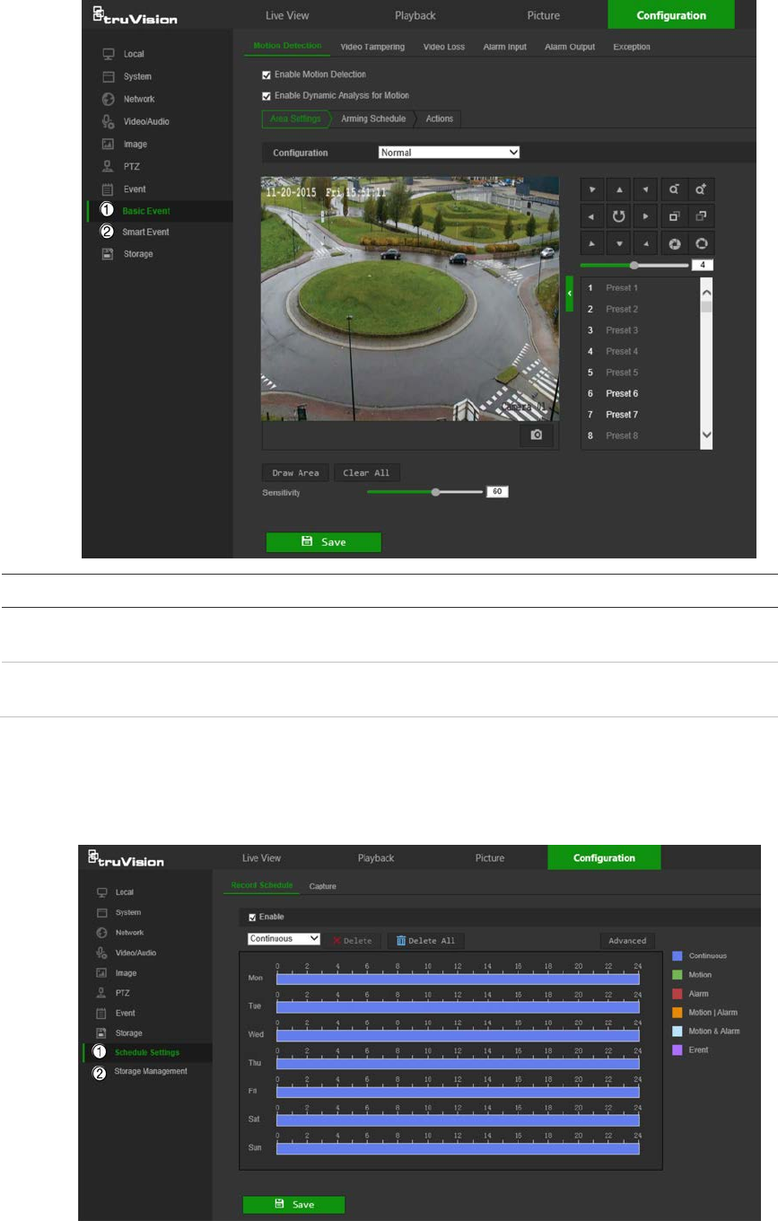
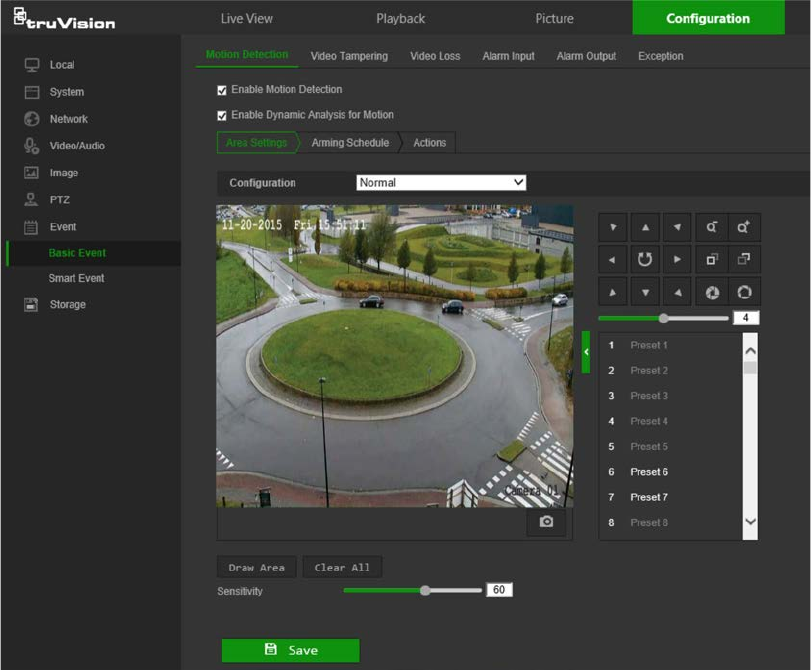
To set up motion detection in normal mode:
1. From the menu toolbar, click Configuration > Event > Basic Event > Motion
Detection.
2. Select the Enable Motion Detection check box. Select Enable Dynamic Analysis
for Motion to see real-time motion events.
Note: Select Local > Rules > Disable to not have detected objects indicated by
green rectangles.
3. Select Normal from the Configuration drop-down list.
4. Click Draw Area. Click and drag the mouse on the live video image to draw an area
sensitive to motion detection.
Note: Up to eight motion detection areas can be drawn on the same image.
5. Click Stop Drawing to finish drawing. Click Clear All to delete all areas marked and
restart drawing.
6. Move the Sensitivity slider to set the sensitivity of the detection. All areas will have
the same sensitivity level.
7. Click Save to save changes.
38 TruVision Stainless Steel PTZ Camera Configuration Manual
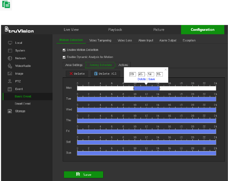
8. Click the Arming Schedule tab to edit the arming schedule. Click and drag along
the time bars or click on a time bar to configure arming schedule times.
Note: All scheduled times are based on the 24-hour clock. Ensure that the correct
time zone and daylight saving time settings have been configured in Configuration
> System > System Settings.
9. Click to copy the schedule to other days by selecting the corresponding check
box next to the day.
10. Click Save to save changes.
11. Click the Actions tab to specify the linkage method for when an event occurs.
Select one or more response methods for the system when an alarm is triggered.
See “Linkage methods” on page 37 for details.
12. Click Save to save changes.
To set up motion detection in advanced mode:
1. From the menu toolbar, click Configuration > Basic Event > Motion Detection.
2. Select the Enable Motion Detection check box. Check Enable Dynamic Analysis
for Motion to see where motion occurs in real-time.
Note: Select Local > Rules > Disable to not have detected objects indicated with
green rectangles.
3. Select Expert from the Configuration drop-down list.
TruVision Stainless Steel PTZ Camera Configuration Manual 39
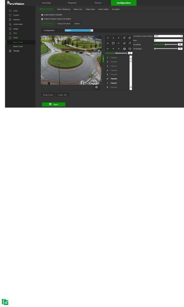
4. In the Image Settings drop-down list, select OFF, Auto-switch or Scheduled-
switch. Default is OFF.
Auto-switch and Scheduled-switch allow permit different settings for day and night
as well as different periods.
5. Select a number from the Area drop-down list and click Draw Area. Click and drag
the mouse on the live video image to draw an area sensitive to motion detection.
Note: Up to eight motion detection areas can be drawn on the same image.
6. Click Stop Drawing to finish drawing. Click Clear All to delete all areas marked and
restart drawing.
7. Move the Sensitivity slider to set the sensitivity of the detection for the selected
areas.
8. Move the Proportion of Object on Area slider to set the proportion of the object
that must occupy the defined area to trigger an alarm.
9. Click Save to save the changes for that area.
10. Repeat steps 7 to 9 for each area to be defined.
11. Click the Arming Schedule tab to edit the arming schedule. Click and drag along
the time bars or click on a time bar to configure arming schedule times.
Note: All scheduled times are based on the 24-hour clock. Ensure that the correct
time zone and daylight saving time settings have been configured in Configuration
> System > System Settings.
12. Click to copy the schedule to other days by selecting the corresponding check
box next to the day.
13. Click Save to save changes.
14. Click the Linkage Method tab to specify the linkage method for when an event
occurs. Select one or more response methods for the system when an alarm is
triggered. See “Linkage methods” on page 37 for details.
15. Click Save to save changes.
40 TruVision Stainless Steel PTZ Camera Configuration Manual
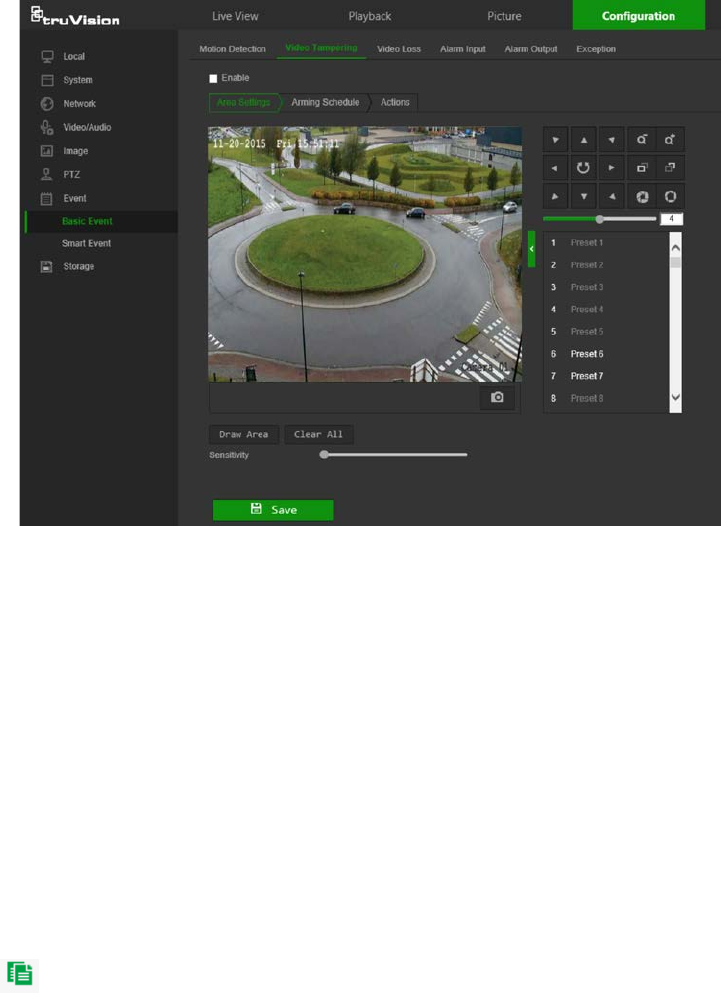
Tamper-proof alarms
The camera can be configured to trigger an alarm when the lens is covered and take an
alarm response action.
To set up tamper-proof alarms:
1. From the menu toolbar, click Configuration > Event > Basic Event > Video
Tampering.
2. Select the Enable check box.
3. Move the Sensitivity slider to set the sensitivity of the detection.
4. Click Save to save changes.
5. Click the Arming Schedule tab to edit the arming schedule. Click and drag along
the time bars or click on a time bar to configure arming schedule times.
Note: All scheduled times are based on the 24-hour clock. Ensure that the correct
time zone and daylight saving time settings have been configured in Configuration
> System > System Settings.
6. Click to copy the schedule to other days by selecting the corresponding check
box next to the day.
7. Click Save to save changes.
8. Click the Actions tab to specify the linkage method for when an event occurs.
Select one or more response methods for the system when an alarm is triggered.
See “Linkage methods” on page 37 for details.
9. Click Save to save changes.
TruVision Stainless Steel PTZ Camera Configuration Manual 41

Alarm inputs and outputs
To define the external alarm input:
1. From the menu toolbar, click Configuration > Event > Basic Event > Alarm Input.
2. Select the Alarm Input No. and the Alarm Type. The alarm type can be NO
(Normally Open) or NC (Normally Closed). Type a name for the alarm into the
Alarm Name box.
3. Click Save to save changes.
4. Click the Arming Schedule tab to edit the arming schedule. Click and drag along
the time bars or click on a time bar to configure arming schedule times.
Note: All scheduled times are based on the 24-hour clock. Ensure that the correct
time zone and daylight saving time settings have been configured in Configuration
> System > System Settings.
5. Click to copy the schedule to other days by selecting the corresponding check
box next to the day.
6. Click the Copy to button to copy the schedule to other alarm inputs.
7. Click Save to save changes.
8. Click the Actions tab to specify the linkage method for when an event occurs.
Select one or more response methods for the system when an alarm is triggered.
See “Linkage methods” on page 37 for details.
For PTZ Linking the options are: Preset No., Patrol No., or Pattern No. Select the
required number.
9. Click the Copy to button to copy the actions to other alarm inputs.
10. Click Save to save changes.
To define alarm output:
1. From the menu toolbar, click Configuration > Event > Basic Event > Alarm
Output.
2. Select an alarm output channel from the Alarm Output No. drop-down list. If
required, type a name for the alarm output in the Alarm Name box.
3. The delay time can be set to 5s, 10s, 30s, 1min, 2min, 5min, or 10min. The delay
time refers to the time duration that the alarm output remains in effect after the
alarm occurs.
4. Click Save to save changes.
5. Click and drag along the time bars or click on a time bar to configure arming
schedule times.
Note: All scheduled times are based on the 24-hour clock. Ensure that the correct
time zone and daylight saving time settings have been configured in Configuration
> System > System Settings.
6. Click to copy the schedule to other days by selecting the corresponding check
box next to the day.
42 TruVision Stainless Steel PTZ Camera Configuration Manual
7. Click the Copy to button to copy the schedule to other alarm inputs.
8. Click Manual Alarm to generate a test alarm. After setting a manual alarm, click
Clear Alarm to remove it.
9. Click Save to save changes.
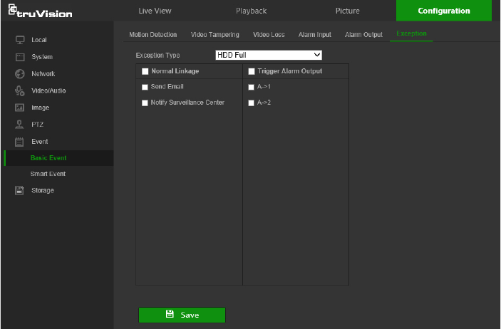
Exception alarms
The camera can be configured for notification of irregular events. These exception
alarms include:
• HDD Full: All recording space of NAS or local storage is full.
• HDD Error: Errors occurred while files were being written to the storage, no storage
is present, or the storage failed to initialize.
• Network Disconnected: Disconnected network cable.
• IP Address Conflicted: Conflict in IP address setting.
• Illegal Login: Wrong user ID or password used to log in to the cameras.
To define exception alarms:
1. From the menu toolbar, click Configuration > Event > Basic Event > Exception.
2. Under Exception Type, select an exception type from the drop-down list.
3. Click the Linkage Method tab to specify the linkage method for when an event
occurs. Select one or more response methods for the system when an alarm is
triggered. See “Linkage methods” on page 37 for details.
4. Click Save to save changes.
Smart event
Audio exception detection
Audio exception detection detects sounds that are above a selected threshold.
TruVision Stainless Steel PTZ Camera Configuration Manual 43
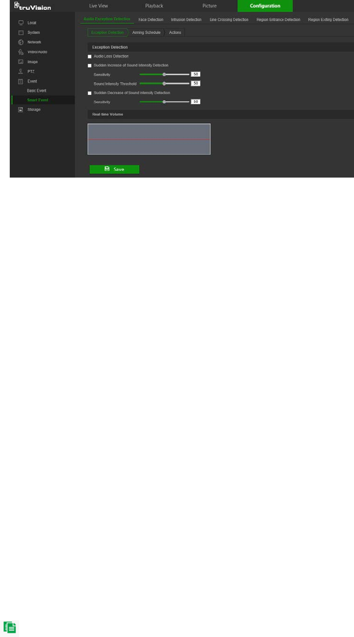
To define audio exception detection:
1. From the menu toolbar, click Configuration > Smart Event > Audio Exception
Detection.
2. Select the Audio Loss Exception check box to activate the function.
3. Select the Sudden Increase of Sound Intensity Detection check box to detect a
steep rise in the sound level of the surveillance scene. You can set the detection
sensitivity and threshold for a sudden increase.
Sensitivity: The smaller the value, the larger the change should be to trigger the
detection. The range is between 1 and 100.
Sound Intensity Threshold: This option filters the sound in the environment. The
louder the environmental sound, the higher the value. Adjust it according to the
actual environment. The range is between 1 and 100.
4. Select the Sudden Decrease of Sound Intensity Detection check box to detect a
steep drop in the sound level of the surveillance scene. You can set the detection
sensitivity and threshold for sound steep drop.
Sensitivity: The smaller the value, the larger the change should be to trigger the
detection. The range is between 1 and 100.
Sound Intensity Threshold: This option filters the sound in the environment. The
louder the environmental sound, the higher the value. Adjust it according to the
actual environment. The range is between 1 and 100.
5. Click the Arming Schedule tab to edit the arming schedule. Click and drag along
the time bars or click on a time bar to configure arming schedule times.
Note: All scheduled times are based on the 24-hour clock. Ensure that the correct
time zone and daylight saving time settings have been configured in Configuration
> System > System Settings.
6. Click to copy the schedule to other days by selecting the corresponding check
box next to the day.
7. Click Save to save changes.
44 TruVision Stainless Steel PTZ Camera Configuration Manual
8. Click the Actions tab to specify the linkage method for when an event occurs.
Select one or more response methods for the system when an alarm is triggered.
See “Linkage methods” on page 37 for details.
9. Click Save to save changes.
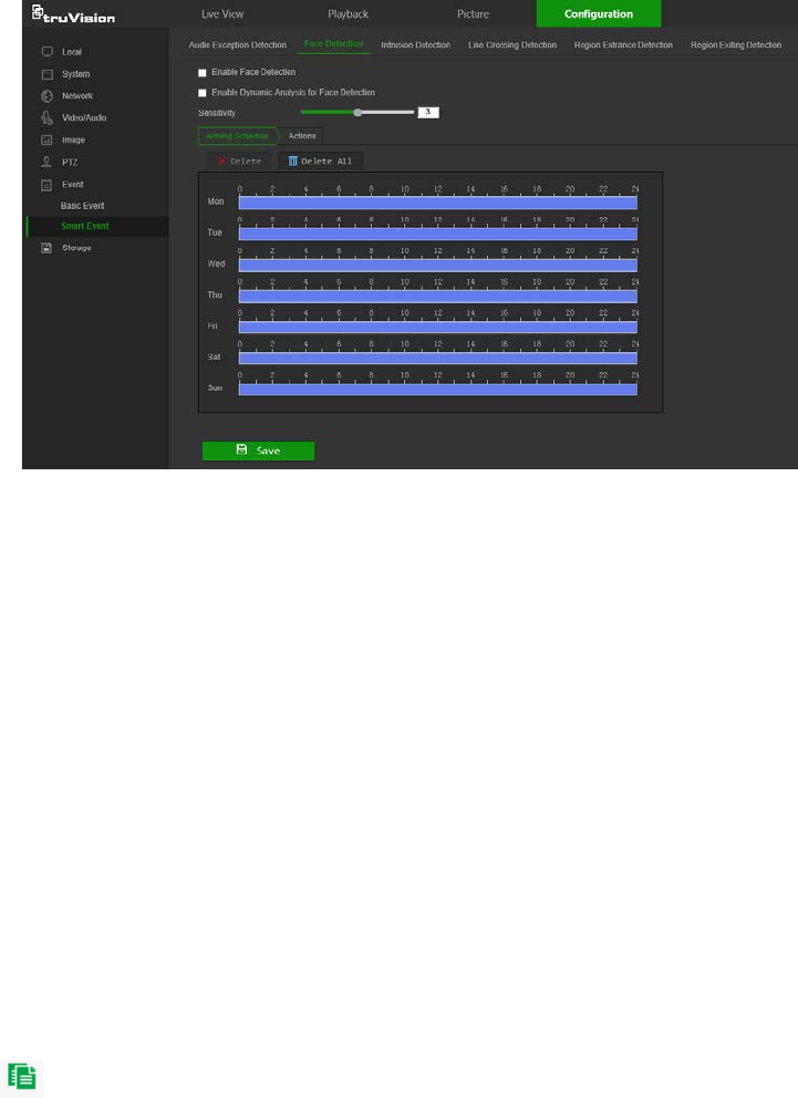
Face detection
When the face detection function is enabled, the camera can detect a human face that
is moving towards it, triggering a configurable response. The camera can only detect a
face looking directly into the camera, not side views. This feature is best suited when
the camera is in front of a door or is located in a narrow corridor.
To define face detection:
1. From the menu toolbar, click Configuration > Smart Event > Face Detection.
2. Check Enable Face Detection to enable the function.
3. Check Enable Dynamic Analysis for Face Detection if you want the face detected
to be marked with a green frame in live view.
Note: If you do not want the detected face marked with the green frame, select
Disable from Configuration > Local Configuration > Live View Parameters >
Rules.
4. Configure the sensitivity of the face detection. The range is between 1 and 5.
5. Click and drag along the time bars or click on a time bar to configure arming
schedule times.
Note: All scheduled times are based on the 24-hour clock. Ensure that the correct
time zone and daylight saving time settings have been configured in Configuration
> System > System Settings.
6. Click to copy the schedule to other days by selecting the corresponding check
box next to the day.
7. Click Save to save changes.
TruVision Stainless Steel PTZ Camera Configuration Manual 45
8. Click the Actions tab to specify the linkage method for when an event occurs.
Select one or more response methods for the system when an alarm is triggered.
See “Linkage methods” on page 37 for details.
9. Click Save to save changes.
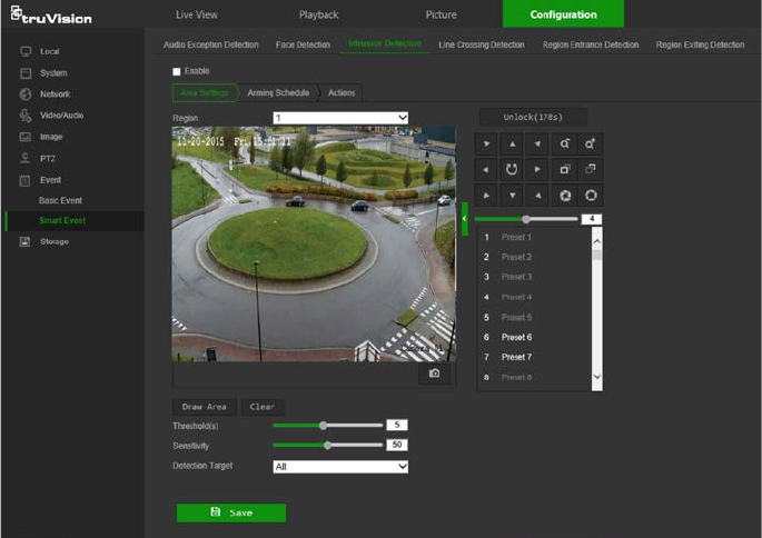
Intrusion detection
An area in the surveillance scene can be configured to detect when intrusion occurs. If
someone enters the area, a set of alarm actions can be triggered.
To define intrusion detection:
1. From the menu toolbar, click Configuration > Event > Smart Event > Intrusion
Detection.
2. Select the Enable check box to enable intrusion detection.
3. Select the region number to be configured from the Region drop-down list.
4. Click Draw Area, and then draw a rectangle on the image as the defense region.
When drawing the rectangle, connect all lines end-to-end to each other. Up to four
areas are supported. Click Clear to clear the areas drawn. The defense region
parameters can be set up separately.
Note: The drawn area can only be quadrilateral.
5. Set the sliders as follows:
Threshold: This is the time threshold that the object remains in the region. If the
value is set as 0, the alarm is triggered immediately after the object enters the
region. The range is between 0 and 100.
Sensitivity: The sensitivity value defines the size of the object that can trigger the
alarm. When the sensitivity is high, a small object can trigger the alarm. The range
is between 1 and 100.
46 TruVision Stainless Steel PTZ Camera Configuration Manual
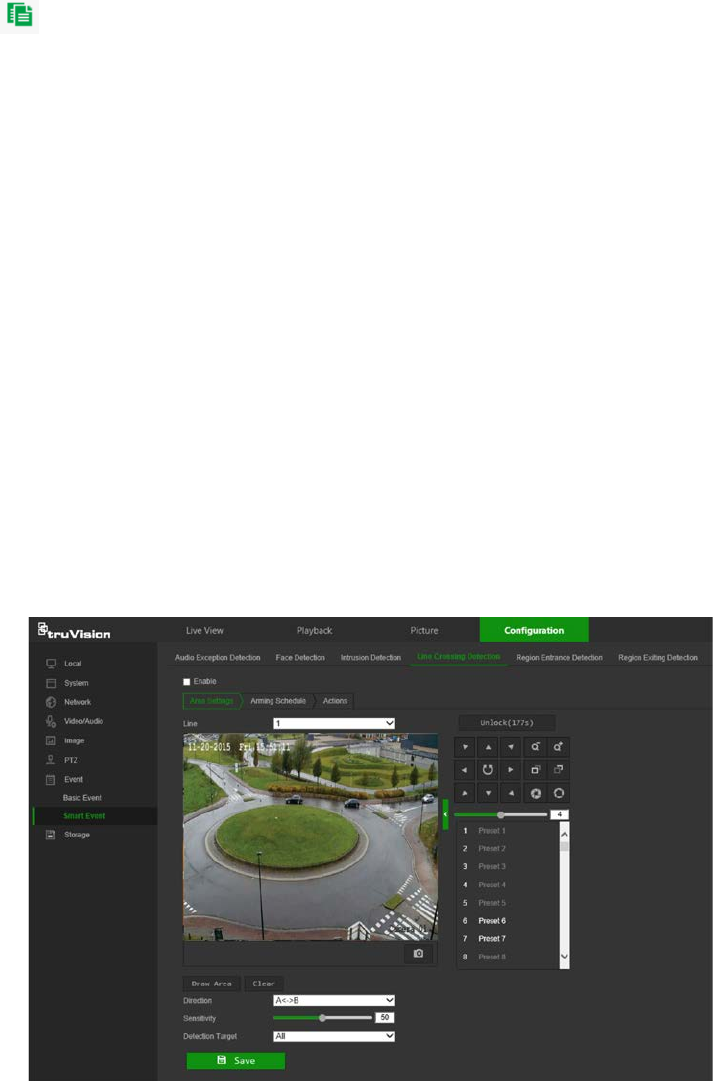
6. Select an option from the Detection Target drop-down list to set the target type that
can trigger an alarm. Options are All, Human, and Vehicle.
7. Click Save to save changes.
8. Click the Arming Schedule tab to edit the arming schedule. Click and drag along
the time bars or click on a time bar to configure arming schedule times.
Note: All scheduled times are based on the 24-hour clock. Ensure that the correct
time zone and daylight saving time settings have been configured in Configuration
> System > System Settings.
9. Click to copy the schedule to other days by selecting the corresponding check
box next to the day.
10. Click Save to save changes.
11. Click the Actions tab to specify the linkage method for when an event occurs.
Select one or more response methods for the system when an alarm is triggered.
See “Linkage methods” on page 37 for details.
12. Click Save to save changes.
Cross line detection
This function can be used to detect people, vehicles, and objects crossing a pre-defined
line or an area on-screen. The line crossing direction can be set as unidirectional or bi-
directional. Unidirectional is crossing the line from left to right or from right to left. Bi-
directional is crossing the line from both directions.
A series of linkage methods can be triggered if an object is detected crossing the line.
To define cross line detection:
1. From the menu toolbar, click Configuration > Event > Smart Event > Line
Crossing Detection.
2. Select the Enable check box to enable the function.
TruVision Stainless Steel PTZ Camera Configuration Manual 47

3. Select the line number to be configured from the Line drop-down list.
4. Click Draw Area. A crossing plane appears on the image.
5. Click the line and two red squares that appear at each end. Drag one of the red
squares to define the arming area.
Select the direction as A<->B, A ->B, or B->A from the drop-down list:
• A<->B: Only the arrow on the B side is displayed. When an object moves across
the plane in both directions, it is detected and alarms are triggered.
• A->B: Only an object crossing the pre-defined line from the A to the B side can
be detected and trigger an alarm.
• B->A: Only an object crossing the pre-defined line from the B to the A side can
be detected and trigger an alarm.
6. Set the sensitivity level between 1 and 100.
7. If required, select another line crossing area to configure from the Line drop-down
list and repeat steps 3-5. Up to four line crossing areas can be configured.
8. Click Save to save changes.
9. Click the Arming Schedule tab to edit the arming schedule. Click and drag along
the time bars or click on a time bar to configure arming schedule times.
Note: All scheduled times are based on the 24-hour clock. Ensure that the correct
time zone and daylight saving time settings have been configured in Configuration
> System > System Settings.
10. Click to copy the schedule to other days by selecting the corresponding check
box next to the day.
11. Click Save to save changes.
12. Click the Actions tab to specify the linkage method for when an event occurs.
Select one or more response methods for the system when an alarm is triggered.
See “Linkage methods” on page 37 for details.
13. Click Save to save changes.
Region Entrance Detection
This function can be used to detect people, vehicles, and objects entering a pre-defined
area on-screen.
To define region entrance detection:
1. From the menu toolbar, click Configuration > Event > Smart Event > Region
Entrance Detection.
2. Select the Enable check box to enable the function.
3. Select the region number to be configured from the Region drop-down list.
4. Click Draw Area, and then draw a rectangle on the image as the defense region.
48 TruVision Stainless Steel PTZ Camera Configuration Manual

When drawing the rectangle, connect all lines end-to-end to each other. Up to four
areas are supported. Click Clear to clear the areas drawn. The defense region
parameters can be set up separately.
Note: The drawn area can only be quadrilateral.
5. Select an option from the Detection Target drop-down list to set the target type that
can trigger an alarm. Options are All, Human, and Vehicle.
6. Click Save to save changes.
7. Click the Arming Schedule tab to edit the arming schedule. Click and drag along
the time bars or click on a time bar to configure arming schedule times.
Note: All scheduled times are based on the 24-hour clock. Ensure that the correct
time zone and daylight saving time settings have been configured in Configuration
> System > System Settings.
8. Click to copy the schedule to other days by selecting the corresponding check
box next to the day.
9. Click Save to save changes.
10. Click the Actions tab to specify the linkage method for when an event occurs.
Select one or more response methods for the system when an alarm is triggered.
See “Linkage methods” on page 37 for details.
11. Click Save to save changes.
Region Exiting Detection
This function can be used to detect people, vehicles, and objects exiting a pre-defined
area on-screen.
To define region exiting detection:
1. From the menu toolbar, click Configuration > Event > Smart Event > Region
Exiting Detection.
2. Select the Enable check box to enable the function.
3. Select the region number to be configured from the Region drop-down list.
4. Click Draw Area, and then draw a rectangle on the image as the defense region.
When drawing the rectangle, connect all lines end-to-end to each other. Up to four
areas are supported. Click Clear to clear the areas drawn. The defense region
parameters can be set up separately.
Note: The drawn area can only be quadrilateral.
5. Select an option from the Detection Target drop-down list to set the target type that
can trigger an alarm. Options are All, Human, and Vehicle.
6. Click Save to save changes.
7. Click the Arming Schedule tab to edit the arming schedule. Click and drag along
the time bars or click on a time bar to configure arming schedule times.
TruVision Stainless Steel PTZ Camera Configuration Manual 49
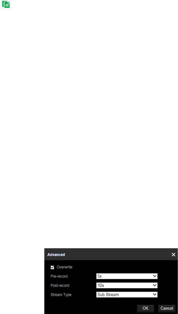
Note: All scheduled times are based on the 24-hour clock. Ensure that the correct
time zone and daylight saving time settings have been configured in Configuration
> System > System Settings.
8. Click to copy the schedule to other days by selecting the corresponding check
box next to the day.
9. Click Save to save changes.
10. Click the Actions tab to specify the linkage method for when an event occurs.
Select one or more response methods for the system when an alarm is triggered.
See “Linkage methods” on page 37 for details.
11. Click Save to save changes.
Schedule settings
Recording schedule
Use the Record Schedule window to define a recording schedule for the camera. The
recording is saved to the SD card or the NAS in the camera. The camera’s SD card
provides a backup in case of network failure.
The selected recording schedule applies to all alarm types.
To set up a recording schedule:
1. From the menu toolbar, click Configuration > Storage > Schedule Settings >
Record Schedule.
2. Select the Enable check box to enable recording.
Note: To disable recording, deselect the option.
3. Click Advanced to set the camera record parameters. Select Overwrite to
overwrite the recording. Configure Pre-record, Post-record, and Stream Type.
Pre-record time
The pre-record time is set to start recording before the scheduled time or event. For
example, if an alarm triggers recording at 10:00, and the pre-record time is set as 5
seconds, the camera starts to record at 9:59:55. The pre-record time can be
configured as No Pre-record, 5s, 10s, 15s, 20s, 25s, 30s, or Not Limited.
50 TruVision Stainless Steel PTZ Camera Configuration Manual
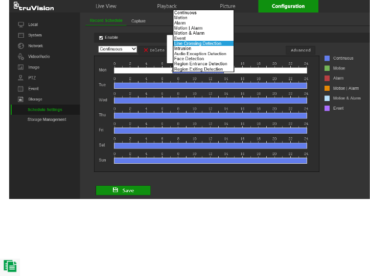
Post-record time
The post-record time is set to stop recording after the scheduled time or the event.
For example, if an alarm triggered recording ends at 11:00, and the post-record time
is set as 5 seconds, the camera records until 11:00:05. The post-record time can be
configured as 5s, 10s, 30s, 1min, 2min, 5min, or 10min.
4. Select a recording type from the drop-down list:
• Schedule: For scheduled recording.
• Motion: Video is recorded when the motion is detected.
• Alarm (Desktop cameras only): Video is recorded when the alarm is triggered
via the external alarm input.
• Motion | Alarm (Desktop cameras only): Video is recorded when the external
alarm is triggered or motion is detected.
• Motion & Alarm (Desktop cameras only): Video is recorded when motion and
alarms are triggered at the same time.
• Event: Video is recorded if the configured alarms for events (cross line
detection, intrusion, audio exception detection, face detection, region entrance or
exit detection) are triggered.
5. Click and drag along the time bars or click on a time bar to configure recording
schedule times and alarm/event types.
Note: All scheduled times are based on the 24-hour clock. Ensure that the correct
time zone and daylight saving time settings have been configured in Configuration
> System > System Settings.
6. Click to copy the schedule to other days by selecting the corresponding check
box next to the day.
7. Click Save to save changes.
Note: If the recording type is set to a motion and/or alarm setting, an arming schedule
must also be defined in order to trigger motion detection or alarm input recording.
TruVision Stainless Steel PTZ Camera Configuration Manual 51
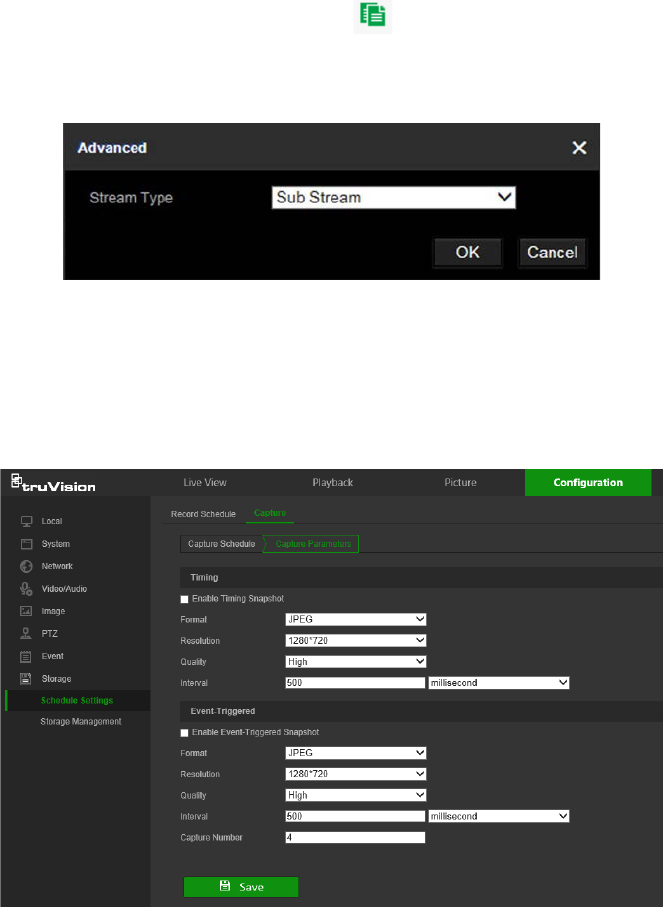
Snapshot parameters
Scheduled and event-triggered snapshots can be captured and stored in the camera’s
SD card or in a NAS (if configured). The snapshots can also be uploaded to an FTP
server.
Select the Enable Timing Snapshot check box to have snapshots uploaded to the
FTP. Also, ensure that the Upload Snapshot check box in the Network > Advanced
Settings > FTP tab is selected to upload snapshots to the FTP.
Select the Enable Event-Triggered Snapshot check box to have snapshots uploaded
to the FTP and/or NAS when motion detection or an alarm input is triggered. Also,
ensure that the Upload Snapshot check box in the Network > Advanced Settings >
FTP tab is selected to upload snapshots to the FTP.
To set up a snapshot schedule:
1. From the menu toolbar, click Configuration > Storage > Schedule Settings >
Capture.
2. Click the Capture Schedule tab to configure the capture schedule by clicking and
dragging the mouse on the time bar. Click to copy the schedule to other days by
selecting the corresponding check box next to the day.
3. Click Advanced to select stream type (Sub Stream or Main Stream).
4. Click Save to save changes.
To set up timed snapshots:
1. From the menu toolbar, click Configuration > Storage > Schedule Settings >
Capture > Capture Parameters.
52 TruVision Stainless Steel PTZ Camera Configuration Manual
2. Select Enable Timing Snapshot to enable continuous snapshots.
3. Select the file format for the snapshot from the Format drop-down list.
4. Select the resolution and quality of the snapshot from the Resolution and Quality
drop-down lists.
5. Enter the time interval between two snapshots. Select the unit of time from the drop-
down list: millisecond, second, minute, hour, or day.
6. Click Save to save changes.
To set up event-triggered snapshots:
1. From the menu toolbar, click Configuration > Storage > Schedule Settings >
Capture > Capture Parameters.
2. Check Enable Event-triggered Snapshot to enable event-triggered snapshots.
3. Select the file format for the snapshot from the Format drop-down list.
4. Select the resolution and quality of the snapshot from the Resolution and Quality
drop-down lists.
5. Enter the time interval between two snapshots. Select the unit of time from the drop-
down list: millisecond, second, minute, hour, or day.
6. Under Capture Number, enter the total number of snapshots required.
7. Click Save to save changes.
Storage management
Use the storage management window to display the capacity, free space available, and
the working status of NAS hard drives and the SD card in the camera. These storage
devices can also be formatted in the Storage Management window.
Before formatting the storage device, stop all recording. Reboot the camera after
formatting is complete, otherwise the device will not function properly.
If Overwrite is selected, the oldest files are overwritten when the storage becomes full.
TruVision Stainless Steel PTZ Camera Configuration Manual 53
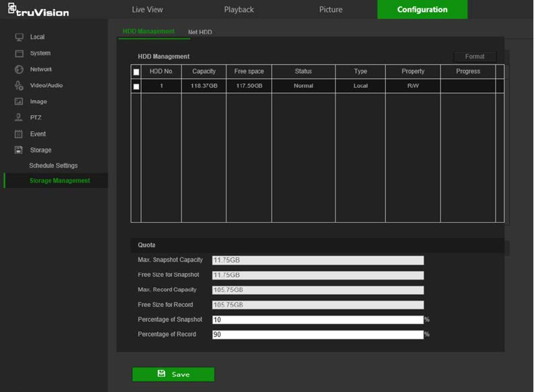
To format the storage devices:
1. From the menu toolbar, click Configuration > Storage > Storage Management >
HDD Management.
2. Select the check box next to the HDD No. of the hard drive to be formatted.
3. Define the quota percentage for snapshots and recordings by modifying the values
in the Percentage of Snapshot and Percentage of Record boxes.
4. Click Format. A formatting permissions window appears.
5. Click OK to start formatting the hard drive.
NAS settings
A network attached storage (NAS) device can be used to remotely store recordings.
To configure recording settings, ensure that one or more NAS disks are available within
the network and correctly configured to store the recorded files, log files, etc.
Notes:
• Up to eight NAS disks can be connected to a camera.
• To prevent formatting failure, we recommend NAS drives with a capacity between
9 GB and 2 TB.
54 TruVision Stainless Steel PTZ Camera Configuration Manual
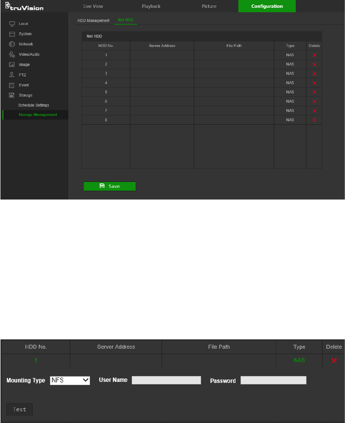
To set up a NAS system:
1. From the menu toolbar, click Configuration > Storage > Storage Management >
Net HDD.
2. Click inside the NAS table to type the IP address and the file path of the network
disk in the appropriate HDD No. row.
3. Select the hard drive mounting protocol (NFS or SMB/CIFS). A user name and
password are required if SMB/CIFS is selected.
4. Click Save to save changes.
TruVision Stainless Steel PTZ Camera Configuration Manual 55
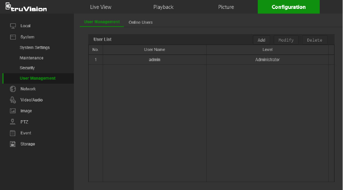
Camera management
This chapter describes how to use the camera’s web browser interface to manage
users, configure security settings, and perform camera maintenance.
User management
This section describes how to:
Add or delete users
Modify permissions
Modify passwords
Only the administrator can manage users. The administrator can create up to 31
individual users for the cameras listed in this manual (see “Introduction” on page 2).
When new users are added to the list, the administrator can modify the permissions
and passwords for each user.
Passwords limit access to the camera and the same password can be used by several
users. When creating a new user, the user must be assigned a password. There is no
default password provided for all users. Users can modify their passwords after they
have been assigned.
Note: Keep the admin password in a safe place. Contact technical support if the
password is forgotten.
Types of users
A user’s access privileges to the system are automatically defined by their user type.
There are three types of users:
Admin: This is the system administrator. The administrator can configure all
settings. Only the administrator can create and delete user accounts. Admin cannot
be deleted.
56 TruVision Stainless Steel PTZ Camera Configuration Manual
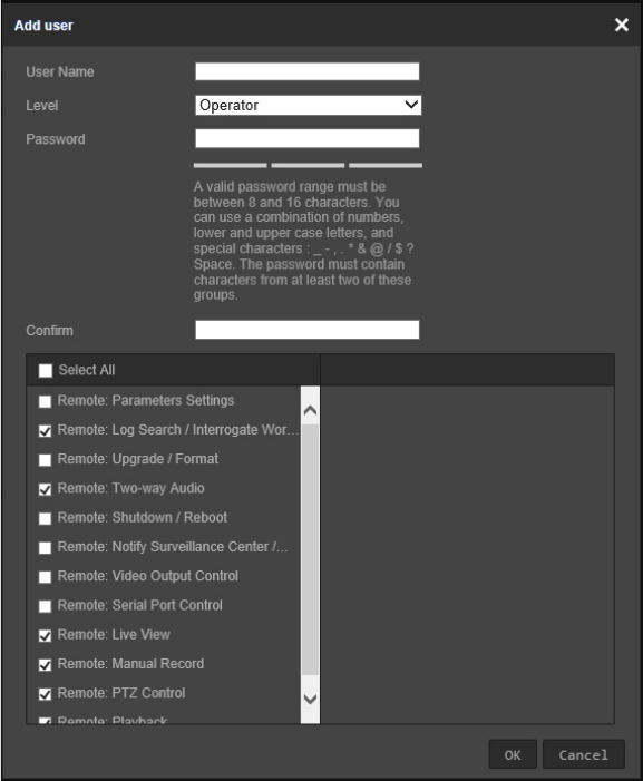
Operator: This user can only change the configuration of his/her own account. An
operator cannot create or delete other users.
Viewer: This user has the permission of live view, playback, and log search.
Viewers cannot change any configuration settings.
Add and delete users
The administrator can create up to 31 users. Only the system administrator can create
or delete users.
To add a user:
1. From the menu toolbar, click Configuration > System > User Management > User
Management.
2. Click the Add button. The user management window appears.
3. Type a name in the User Name box.
4. Assign the user a password. Passwords can have up to 16 alphanumeric
characters.
5. Select the type of user from the Level drop-down list. The options are Viewer and
Operator.
6. Assign permissions to the user. Select from the following permissions:
TruVision Stainless Steel PTZ Camera Configuration Manual 57
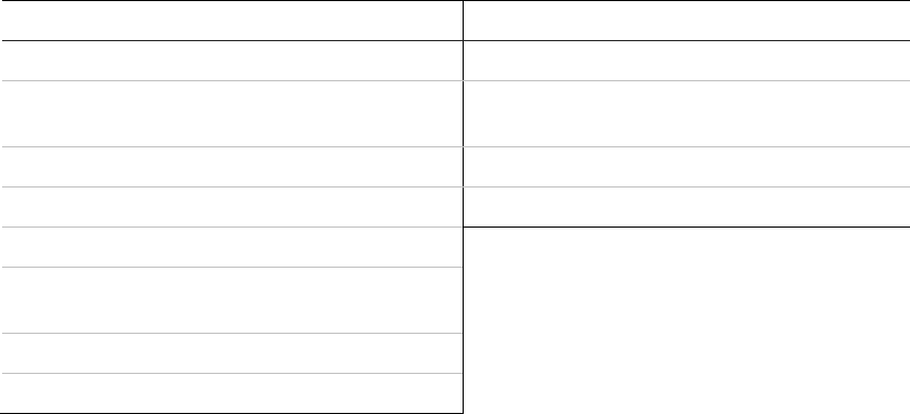
Basic Permissions Camera Configuration
Remote: Parameters Settings Remote: Live View
Remote: Log Search/Interrogate Working
Status Remote: PTZ Control
Remote: Upgrade/Format Remote: Manual Record
Remote: Bi-directional Audio Remote: Playback
Remote: Shutdown/Reboot
Remote: Notify Alarm Recipient/Trigger
Alarm Output
Remote: Video Output Control
Remote: Serial Port Control
7. Click OK to save the settings.
To delete a user:
1. Select a user from the User List.
2. Click the Delete button. A message box appears.
Note: Only the administrator can delete a user.
3. Click Save to save the changes.
To modify user information:
Information about a user such as their name, password, and permissions can be
modified.
To modify user information:
1. Select a user from the User List.
2. Click the Modify button. The user management window appears
3. Change the information required.
Note: The user “Admin” can only be changed by entering the admin password.
4. Click Save to save the changes.
Online users
Click Configuration > System > User Management > Online Users to view the
current users accessing the device through the camera configuration interface.
Information such as user name, level, IP address, and operation time appears in the
User List for each user. Click Refresh to refresh the list.
58 TruVision Stainless Steel PTZ Camera Configuration Manual
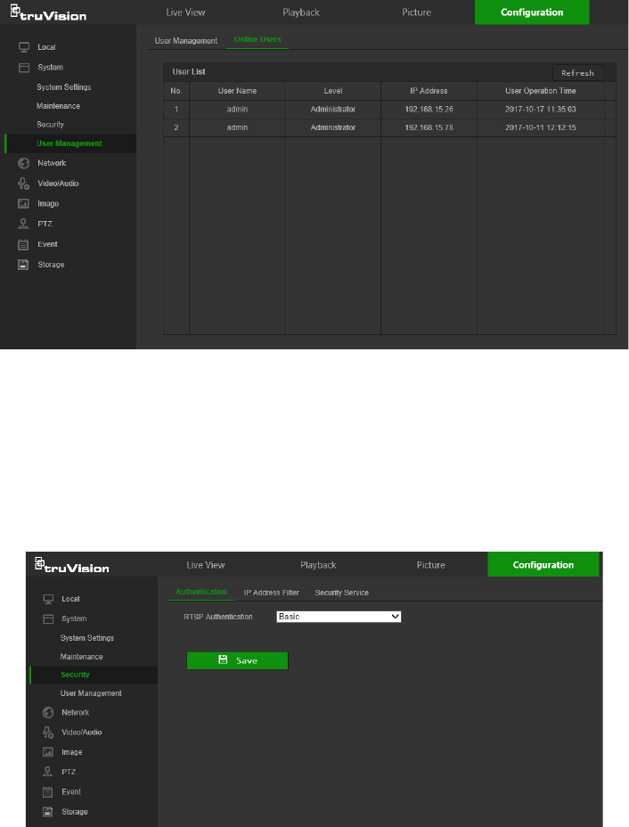
Security
RTSP authentication
Add Real Time Streaming Protocol (RTSP) functionality to Live View streaming in the
Authentication window.
To define RTSP authentication:
1. From the menu toolbar, click Configuration > System > Security >
Authentication.
2. In the RTSP Authentication drop-down list, select Enable or Disable to enable or
disable the RTSP authentication.
3. Click Save to save the changes.
IP address filter
Use the IP address filter window to set access rights for defined IP addresses. For
example, the camera can be configured so that only the IP address of the server
hosting the video management software can be accessed. Attempts by users to access
other IP addresses would be denied.
TruVision Stainless Steel PTZ Camera Configuration Manual 59

To define the IP address filter:
1. From the menu toolbar, click Configuration > Security > IP Address Filter.
2. Select the Enable IP Address Filter check box.
3. Select Forbidden or Allowed from the IP Address Filter Type drop-down list.
4. Click Add to add an IP address.
5. Click Modify or Delete to modify or delete the selected IP address.
6. Click Clear to delete all the IP addresses.
7. Click Save to save the changes.
Security service
Enable the illegal login lock to block the IP address after five failed user
name/password login attempts. After the IP address is locked, a user can log in to the
device after 10 minutes
To enable the illegal login lock:
1. Click Configuration > System > Security > Security Service.
2. Select the Enable Illegal Login Lock check box
3. Click Save to save the changes.
60 TruVision Stainless Steel PTZ Camera Configuration Manual
Maintenance
Reboot camera
The camera can be rebooted remotely.
To reboot the camera through the web browser:
1. Click Configuration > Security > Maintenance > Upgrade & Maintenance.
2. Click the Reboot button to reboot the device.
3. Click OK in the pop-up message box to confirm reboot operation.
Restore default settings
Use the Upgrade & Maintenance tab window to restore factory default settings to the
camera.
Restore: Restore all the parameters, except the IP parameters, to the default
settings.
Default: Restore all the parameters to the default settings.
Note: If the video standard is changed, it will not be restored to its original setting when
Restore or Default is used.
To restore default settings:
1. From the menu toolbar, click Configuration > System > Maintenance > Upgrade
& Maintenance.
2. Click either Restore or Default. A window showing user authentication appears.
3. Enter the admin password and click OK.
4. Click OK in the pop-up message box to confirm restoring operation.
Import or export a configuration file
The administrator can export and import configuration settings from the camera. This is
useful for copying configuration settings from an existing camera to a new camera or
backing up camera settings.
Note: Only the administrator can import or export configuration files.
To import or export a configuration file:
1. Click Configuration > System > Maintenance > Upgrade & Maintenance.
2. Click Browse under Import Config. File to select the local configuration file and then
click Import to start importing the configuration file.
3. Click Export under Export Config. File and set the saving path to save the
configuration file.
Upgrade firmware
The camera firmware is stored in the flash memory. Use the upgrade function to write
the firmware file into the flash memory.
TruVision Stainless Steel PTZ Camera Configuration Manual 61
Firmware should be upgraded when it has become outdated. When upgrading the
firmware, all existing settings are unchanged. Only the new features are added with
their default settings.
The camera selects the corresponding firmware file automatically. Cookies and data in
the web browser are automatically deleted when the firmware is updated.
To upgrade the firmware version:
1. Download the latest camera firmware from our web site at
www.interlogix.com/video/category/ip-cameras.
2. When the firmware file has downloaded, extract the file to the required destination.
Note: Do not save the file on the computer desktop.
3. From the menu toolbar, click Configuration > Security > Maintenance > Upgrade
& Maintenance. Select the Firmware or Firmware Directory option from the
Upgrade drop-down list, and then click the Browse button to locate latest firmware
file on the computer.
• Firmware directory – Locate the folder containing the firmware file. The camera
chooses the appropriate firmware file automatically.
• Firmware – Locate the firmware file manually.
4. Click Update. A prompt to reboot the camera appears.
5. When the upgrade is finished, the device reboots automatically. The browser is also
refreshed.
TruVision Device Manager
Use the Manual Firmware Upgrade function to upgrade the firmware of the selected
device or devices in TruVision Device Manager. Before following the instructions in the
TruVision Device Manager User Manual, ensure that the firmware update file has
already been downloaded to the local computer.
To access the TruVision Device Manager User Manual, go to
www.interlogix.com/video/product/truvision-device-manager and click Downloads.
Searching event logs
Configure NAS storage (see “NAS settings” on page 54) or insert a SD card in the
camera before using the log functions.
The number of event logs that can be stored on NAS or SD card depends on the
capacity of the storage devices. When the capacity limit is reached, the system starts
deleting older events.
Note: View log access rights are required to search and view logs.
62 TruVision Stainless Steel PTZ Camera Configuration Manual
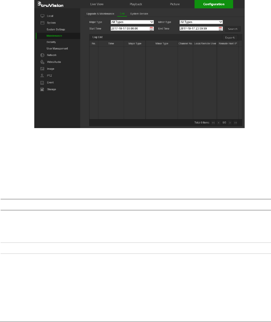
Search for recorded logs using the following criteria:
Major type: There are four types of logs: All Types, Alarm, Exception, and Operation.
Minor type: Each major type log has some minor types.
Date and Time: Logs can be searched by start and end recording time.
Export: Export the Log List to text or Microsoft Excel (XLS) file format.
Main log type
Minor log types: Description of events included
Alarm
Alarm Input, Alarm output, Start Motion Detection, Stop Motion Detection, Start
Tamper-proof, Stop Tamper-proof, Cross Line Detection Started, Cross Line
Detection Stopped, Intrusion Detection Started, Intrusion Detection stopped,
Start PIR Alarm, Stop PIR alarm
Exception
Illegal Login, HDD Full, HDD Error, Network Disconnected, IP Address Conflicted
Operation
Power On, Local Reboot, Local Abnormal Shutdown, Local Login, Local Logout,
Local Configure Parameters, Local Upgrade, Local Start Record, Local Stop
Record, Local Export Config File, Local Import Config File, Remote Reboot,
Remote Login, Remote Logout, Remote Configure parameters, Remote
Upgrade, Remote Start Record, Remote Stop Record, Remote PTZ Control,
Remote Initialize HDD, Remote Playback by File, Remote Playback by Time,
Remote Get Parameters, Remote Get Working Status, Start Bi-directional Audio,
Stop Bi-directional Audio, Remote Alarm Arming, Remote Alarm Disarming,
Remote Export Config File, Remote Import Config File
To search logs:
1. From the menu toolbar, click Configuration > System > Maintenance > Log.
2. In the Major Type and Minor Type drop-down list, select the required option.
3. Select start and end time of the log.
4. Click Search to start the search. The results appear in the window.
TruVision Stainless Steel PTZ Camera Configuration Manual 63
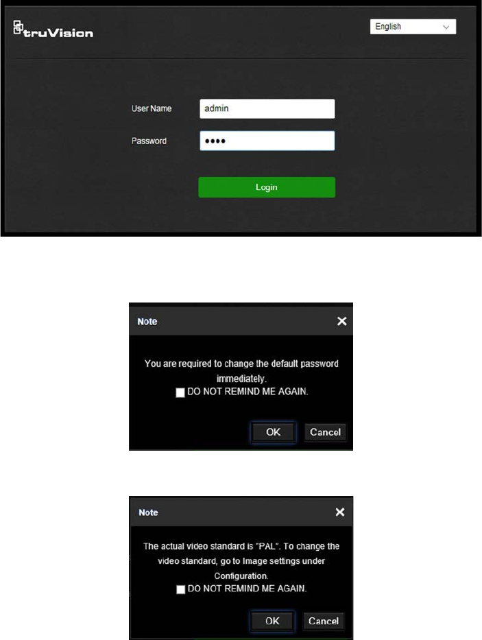
Camera operation
This chapter describes how to use the camera after it is installed and configured.
Logging on and off
1. If necessary, log out of the camera browser window by clicking the Logout button
on the menu toolbar. A user name and password are always required when logging
in.
2. If necessary, change the language of the interface from the drop-down list in the top
right corner of the login window.
3. The camera comes with a user account with administrative rights for configuring all
options on the camera. The user name is “admin” and the password is “1234”. Type
in these values and click Login.
4. Initial login: The default password notification appears. Click OK. For enhanced
security, we highly recommend changing the default password during initial setup.
5. Initial login: The video standard notification appears. Click OK.
64 TruVision Stainless Steel PTZ Camera Configuration Manual
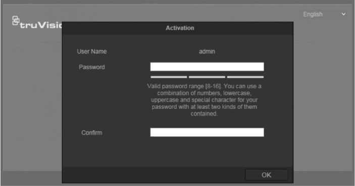
Live view mode
After logging in, click the Live View tab on the menu toolbar to access live view mode.
See “Activating the camera
When you first start up the camera, the Activation window appears. You must define a
high-security admin password before you can access the camera. There is no default
password provided.
You can activate a password via a web browser and via TruVision Device Manager
(included on the CD to find the IP address of the camera).
Activation via the web browser:
1. Power on the camera and connect the camera to the network.
2. Type the IP address into the address bar of the web browser, and press Enter to
enter the activation interface.
Note:
The default IP address of the camera is 192.168.1.70.
For the camera to enable DHCP by default, you must activate the camera via
TruVision Device Manager. Please refer to the following section, “Activation via
TruVision Device Manager”.
3. Type the password in the Password field.
Note: A valid password range must be between 8 and 16 characters. You can use a
combination of numbers, lower and upper case letters, and special characters : _ - ,
. * & @ / $ ? Space. The password must contain characters from at least two of
these groups. We also recommend that you reset your password regularly. For high
security systems, it is particularly recommended to reset the password monthly or
weekly for better protection.
4. Confirm the password.
5. Click OK to save the password and enter the live view interface.
TruVision Stainless Steel PTZ Camera Configuration Manual 65
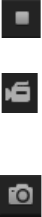
Activation via TruVision Device Manager:
For instructions on how to activate the camera using TruVision Device Manager, refer
to the TruVision Device Manager User Manual.
Go to www.interlogix.com/video/product/truvision-device-manager and click
Downloads.
Overview of the camera web browser” on page 4 for a description of the interface.
Start/stop live view: Stop and start live view by clicking the Start/stop
live view button on the bottom of the window.
Record: Record live video and store it in a configured directory. In the
live view window, click the Record button at the bottom of the window.
To stop recording, click the button again.
Take a snapshot: Take a snapshot of a scene when in live view. Click
the Capture button located at the bottom of the window to save an
image. The image is in JPEG format. Snapshots are saved on the hard
drive.
66 TruVision Stainless Steel PTZ Camera Configuration Manual
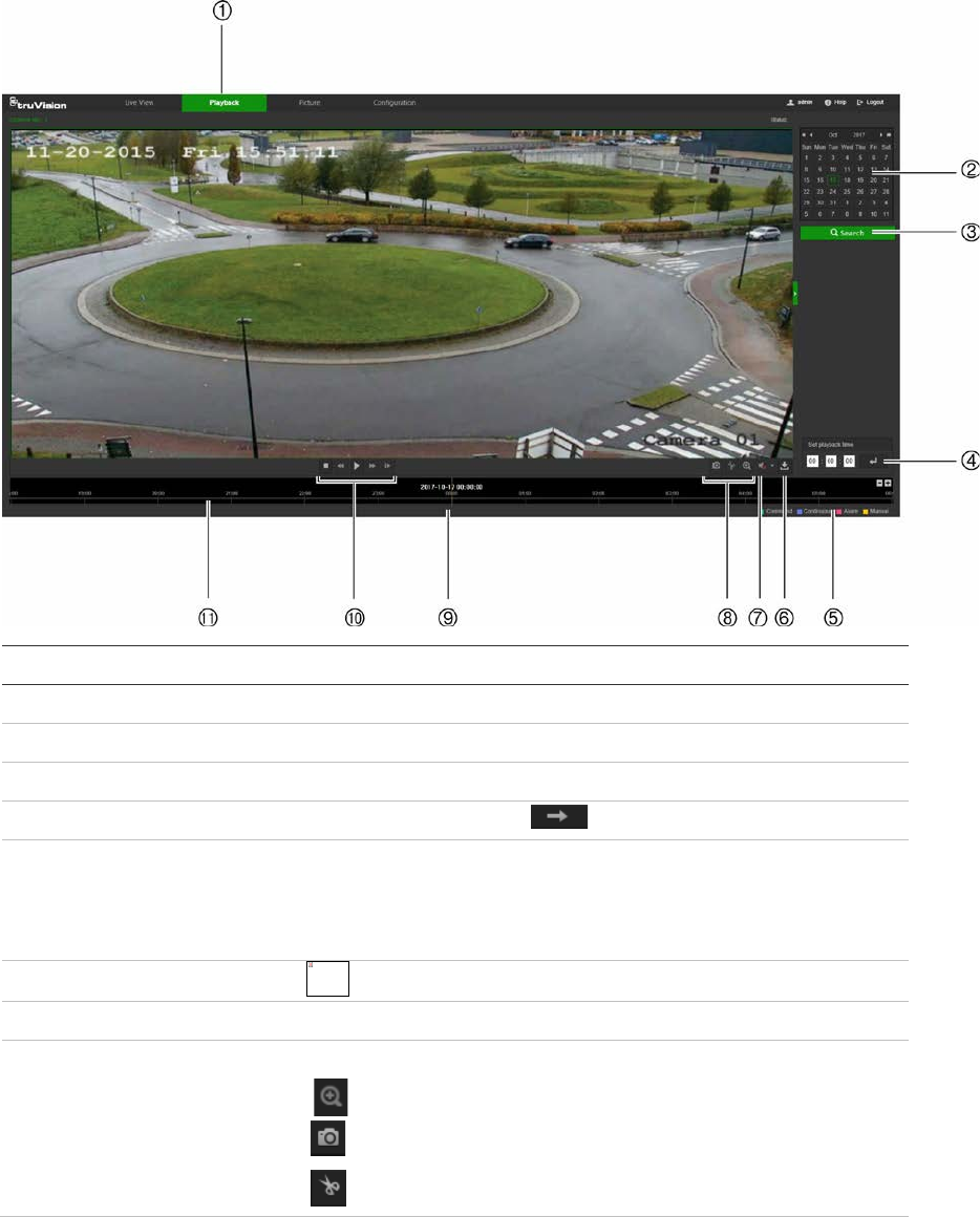
Playing back recorded video
Search for and play back recorded video in the playback interface.
Note: Configure the NAS or insert an SD card in the camera before using the playback
functions. See “Storage ” on page 53 for more information.
To search recorded video stored on the camera’s storage device for playback, click
Playback on the menu toolbar. The Playback window appears.
Name
Description
1
. Playback button Click to open the Playback window.
2
. Search calendar Click the day required to search.
3
. Search Start search.
4
. Set playback time Input the time and click to locate the playback point.
5
. Recording type The color code displays the recording type. Recording types are
Schedule, Alarm, and Manual.
The recording type name is also displayed in the current status
window.
6
. Download functions
Download video files.
7
. Audio control Control level of audio.
8
. Archive functions Click these buttons for the following archive actions:
Enable digital zoom.
Capture a snapshot image of the playback video.
Start/Stop clipping video files.
The linked image cannot be displayed. The file may have been moved, renamed, or deleted. Verify that the link points to the correct file and location.
TruVision Stainless Steel PTZ Camera Configuration Manual 67
Name
Description
9
. Time moment Vertical bar shows the current position within the playback
recording. The current time and date are also displayed.
10
. Control playback Click to control how the selected file is played back: Play, Stop,
Slow or Fast Forward playback, and Single Frame playback.
11
. Timeline bar The timeline bar displays the 24-hour period of the day being
played back. It moves left (oldest) to right (newest). The bar is
color-coded to display the type of recording.
Click a location on the timeline to move the cursor to a time for
playback to start. The timeline can also be scrolled to earlier or
later periods for playback.
Click to zoom in and out on the timeline bar.
To play back recorded video:
1. Select the date and click the Search button. The searched video appears in the
timeline.
2. Click Play to start playback. While playing back a video, the timeline bar displays
the type and time of the recording. The timeline can be manually scrolled using the
mouse.
Note: Playback permission is required to play back recorded images. See “To
modify user information” on page 58 for more information.
3. Select the date and click the Search button to search for a recorded file.
4. Click to search the video file.
5. In the pop-up window, select the check box next to the video file and click
Download to download the video files.
To archive a recorded video segment during playback:
1. While playing back a recorded file, click to start clipping. Click it again to stop
clipping. A video segment is created.
2. Repeat step 1 to create additional segments. The video segments are saved on the
local computer.
Operating PTZ control
In the live view interface, use the PTZ control buttons to control pan/tilt/zoom and other
functions of the camera (where supported).
PTZ control panel
In live view, click / to display/hide the PTZ control panel.
68 TruVision Stainless Steel PTZ Camera Configuration Manual
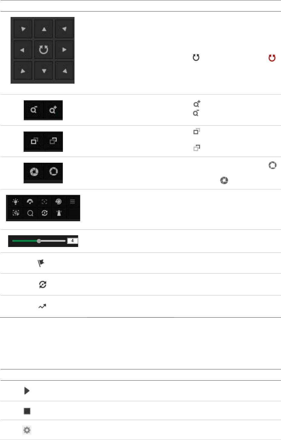
Button
Name Description
PTZ Control Panel
Hold and press the direction buttons
to pan/tilt the camera.
Click to pan the camera. Click
to stop panning.
Zoom in/out Click to zoom in.
Click to zoom out.
Focus near/far
Click to focus on items far from
the camera.
Click to focus on nearby items.
Iris close/open When the image is too dark, click
to open the iris. When the image is
too bright, click to close the iris.
Auxiliary Functions
The auxiliary functions include light,
wiper, auxiliary focus, lens
initialization, manual tracking, 3D
positioning, one-touch patrol, one-
touch park, and on-screen menu.
Speed Adjustment Adjusts the speed of pan/tilt
movements.
Preset See “Presets” on page 70.
Patrol See “Patrols” on page 72.
Pattern See “Patterns” on page 73.
Note: To perform pan/tilt movement using the direction buttons, the PTZ parameters in
the RS-485 window must be set correctly. See “RS485” on page 12.
Preset/Patrol/Patterns buttons
Button
Description
Start the selected patrol/pattern.
Stop current patrol/pattern.
Set the selected preset/patrol.
TruVision Stainless Steel PTZ Camera Configuration Manual 69
Button
Description
Delete the selected preset/patrol/pattern.
Start recording a pattern.
Stop recording the pattern.
Auxiliary function buttons
Button
Description
Light. Click this button to enable/disable the camera light. This function is
reserved.
Wiper. Click this button to move the wiper once.
Auxiliary focus. This function is reserved.
Manual tracking. Select Enable Smart Tracking (Configuration > PTZ > Smart
Tracking) to use this function.
Click this button and then click on a moving object in live video. The camera tracks
the object automatically.
3D positioning. Click this button and then click in live video to move that camera
position into the center of the live video.
Hold down the left mouse button and drag the mouse to the lower right on the live
video. The corresponding position moves to the center of the live video and is
zoomed in.
Hold down the left mouse button and drag the mouse to the upper left on the live
video. The corresponding position moves to the center of the live video and is
zoomed out.
One-touch patrol. See “One-touch patrol” on page 73.
One-touch park. Click this button to save the current view as preset No. 32 and
park the camera at the current position.
Presets
A preset is a predefined image position. A defined preset can be quickly accessed by
clicking the calling button.
To set a preset:
1. Select a preset number from the preset list in the PTZ control panel.
70 TruVision Stainless Steel PTZ Camera Configuration Manual
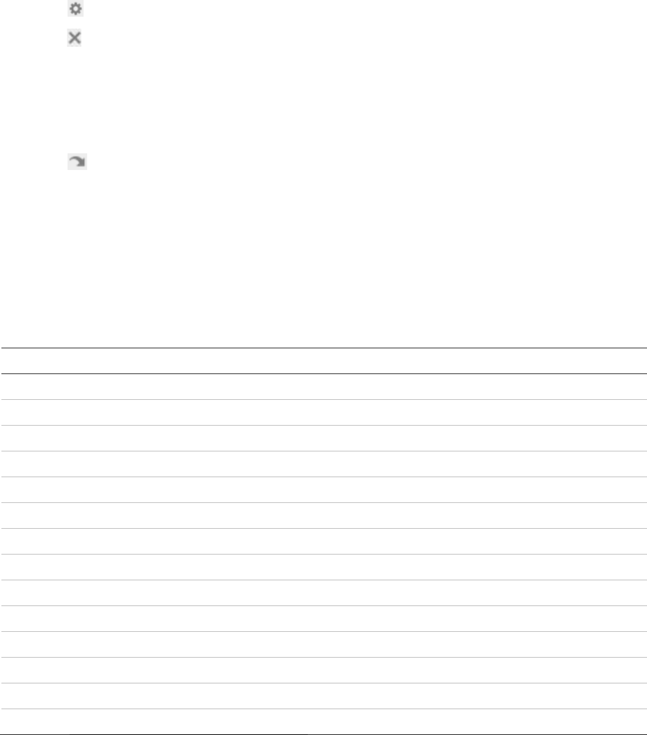
2. Use the PTZ directional buttons to move the camera to the required position.
3. Click to finish the setting of the current preset.
4. Click to delete the preset.
Note: Up to 256 presets can be configured.
To call a preset:
1. Select a defined preset from the list.
2. Click to call the preset, or type the number of the preset required on the
keyboard.
Special presets
• The following presets are predefined with special commands. These presets can be
called but not configured. For example, preset 99 is the “Start auto scan.” If preset
99 is called, the camera starts the auto scan function.
• Preset pattern functions vary depending on camera model.
Preset
Function Preset Function
33
Auto flip 92 Start to set limit stops
34
Back to initial position 93 Set limit stops manually
35
Call patrol 1 94 Remote reboot
36
Call patrol 2 95 Call OSD menu
37
Call patrol 3 96 Stop a scan
38
Call patrol 4 97 Start random scan
39
Day mode (IR cut filter in) 98 Start frame scan
40
Night mode (IR cut filter out) 99 Start auto scan
41
Call pattern 1 100 Start tilt scan
42
Call pattern 2 101 Start panorama scan
43
Call pattern 3 102 Call patrol 5
44
Call pattern 4 103 Call patrol 6
45
One-touch Patrol 104 Call patrol 7
90
Wiper 105 Call patrol 8
TruVision Stainless Steel PTZ Camera Configuration Manual 71
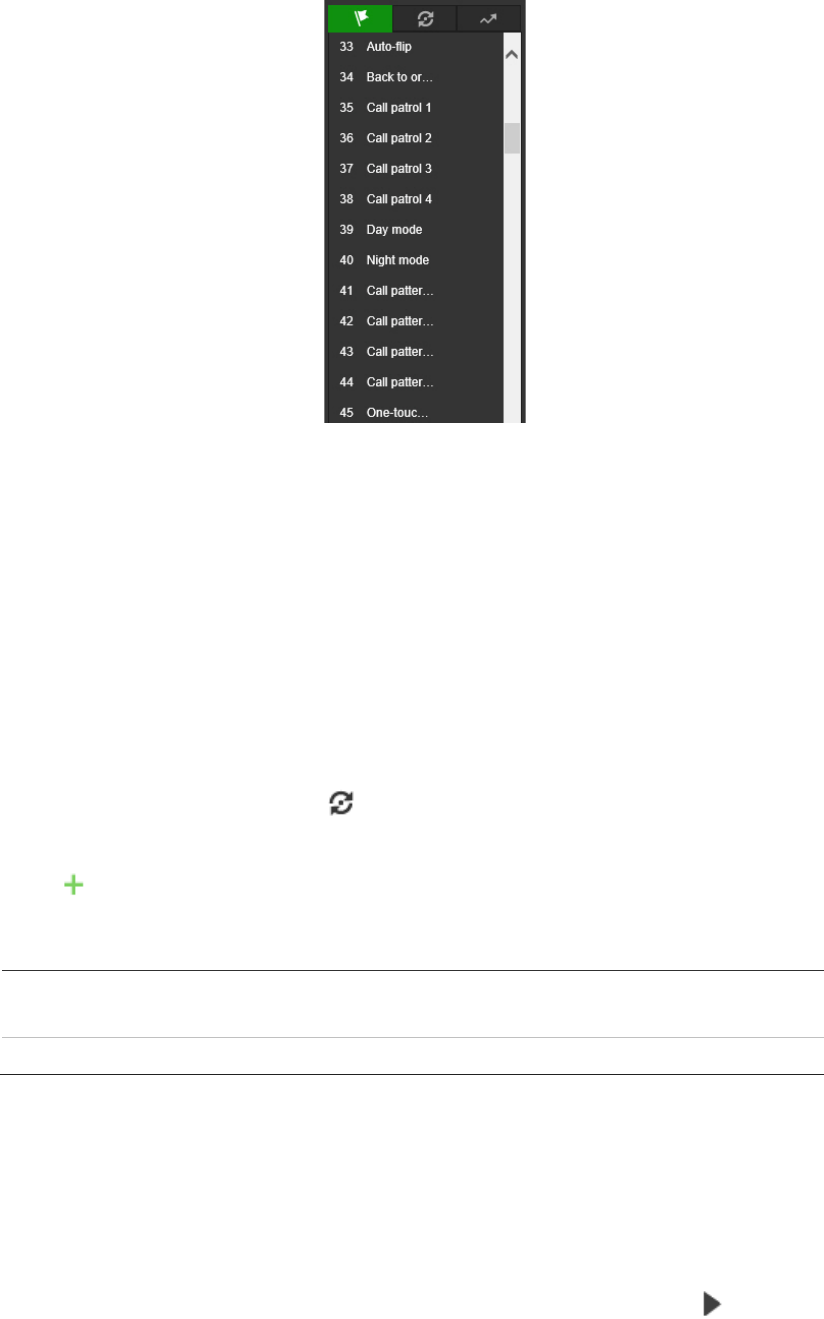
Note: The OSD (On Screen Display) menu may need to be used when controlling the
camera remotely. To display the OSD menu on the live view screen, call the preset
number 95.
Patrols
A patrol is a memorized series of preset functions. The camera stays at a step for a set
dwell time before moving on to the next step. The steps are defined by presets. A patrol
can be configured with up to 32 presets.
You can configure up to eight patrols.
To set a patrol:
1. In the PTZ control panel, click to enter the patrol settings interface.
2. Select a patrol number from the list.
3. Click to enter the adding interface of the preset.
4. Configure the preset number, patrol time, and patrol speed.
P
atrol Duration:
The dwell time. The length of time in seconds for which a
camera stays at a preset before moving to the next preset.
Patrol
Speed: The speed the camera moves from one preset to another.
5. Click OK to save a preset into the patrol.
6. Repeat the steps from 3 to 5 to add more presets.
7. Click OK to save all the patrol settings.
To call a patrol:
In the PTZ control panel, select a defined patrol from the list and click to call the
patrol.
72 TruVision Stainless Steel PTZ Camera Configuration Manual
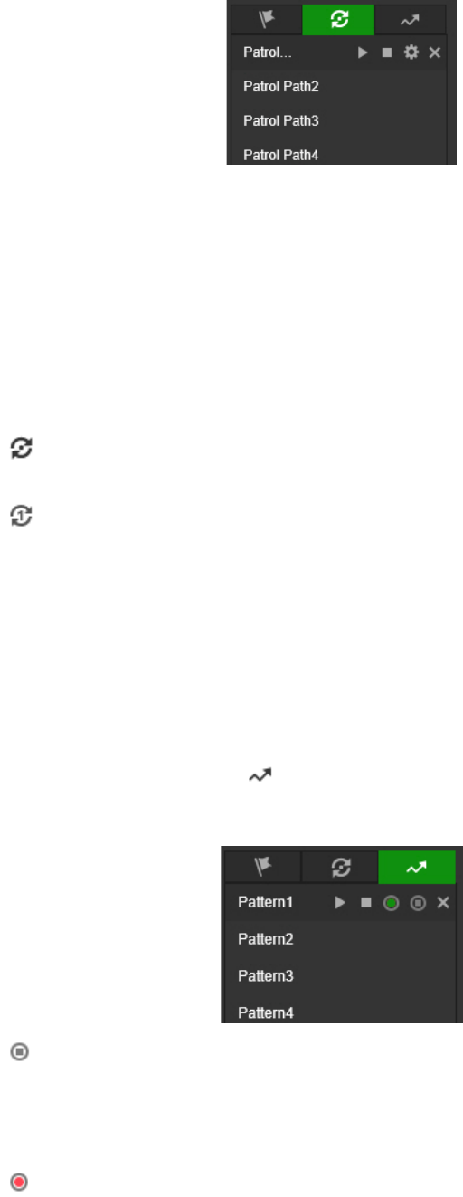
One-touch patrol
One-touch patrol is an automatically created patrol. The system automatically adds
preset No.1 to No. 32 to the patrol path 8. When the one-touch patrol is called the
camera moves as the patrol path 8 automatically.
To activate one-touch patrol:
1. Set preset No.1 to No. 32. See “Presets” on page 70 for further information.
2. Call preset No. 45, and the camera moves as patrol path 8.
3. Click to enter the patrol settings interface and start/stop one-touch patrol, and
edit the patrol time and the speed.
4. Click on the PTZ control panel to start one-touch patrol.
Patterns
A pattern is a memorized series of pan, tilt, zoom, and preset functions. A pattern can
be called using the pattern settings interface. There are up to four patterns that can be
customized.
Note: Pattern functions vary depending on camera model.
To set a pattern:
1. In the PTZ control panel, click to enter the pattern settings interface.
2. Select a pattern number from the list.
3. Click to enable recording the panning, tilting, and zooming actions.
4. Use the PTZ directional buttons to move the camera to the required position after
the PROGRAM PATTERN REMAINING MEMORY(%) information appears on the
screen.
5. Click to save all the pattern settings.
Note: The four patterns can be operated separately and with no priority level.
When configuring and calling the pattern, the proportional pan is valid, the limit
stops and auto flip will be invalid, and the 3D positioning operation is not supported.
TruVision Stainless Steel PTZ Camera Configuration Manual 73
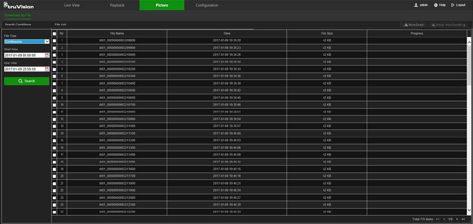
Picture
Note: Follow the instructions under “Snapshot parameters” on page 52 to configure
snapshot capture parameters before using the Picture menu.
Click Picture to launch the picture searching interface. Use this menu to search for,
view, and download the pictures stored in the camera’s SD card or in network storage.
To search the snapshots:
1. Make a selection from the File Type drop-down list. Schedule, Motion, Alarm,
Cross Line, and Intrusion Detection are selectable.
2. Click on the calendar icon in the Start Time and End Time boxes to select the start
time and end time.
3. Click Search to search the matched pictures.
4. Select the check box next to one or more snapshots and then click Download to
download the selected images.
74 TruVision Stainless Steel PTZ Camera Configuration Manual
Index
A
Advanced settings
overview of advanced settings parameters, 16
Alarm inputs
set up, 42
Alarm outputs
set up, 42
Alarm types
motion detection, 36
Archive files
recorded files, 68
snapshots of recorded files, 68
Archived files
play back, 68
Archiving files
set up default directories, 7
Audio parameters, 20
B
Basic settings
overview of basic settings parameters, 13
C
Camera image
configuring, 23
Camera name
display, 26
Capture
description, 52
Certificate
creation and request, 19
Configuration file
import/export, 61
Credentials
default, 2
Cross line detection
set up, 47
D
Date format set up, 26
DDNS parameters
set up, 15
Default settings
credentials, 2
network, 2
restore, 61
Detection
region exiting, 49
Detection
audio exception, 44
cross line, 47
face, 45
intrusion, 46
motion – advanced mode, 39
region entrance, 48
Device manager, 62
Display information on-screen
set up, 26
E
Email parameters
set up, 18
Event settings
overview of event parameters, 9
Events
searching logs, 62
Exception alarm
set up, 43
Exception alarms
types, 43
F
Face detection
set up, 45
Firmware upgrade, 61
device manager, 62
FTP parameters
set up, 17
H
HDD
capacity, 53
error alarm, 43
formatting, 53
full alarm, 43
HTTPS parameters
set up, 19
I
Illegal login alarm, 43
Illegal login lock, 60
Image
overview of PTZ parameters, 9
Intrusion detection
set up, 46
IP address
access rights, 59
filter setup, 60
IP address conflicted alarm, 43
L
Linkage methods, 37
Live view
manual recording, 66
snapshots, 66
TruVision Stainless Steel PTZ Camera Configuration Manual 75
start/stop, 66
Local settings
overview of local camera parameters, 7
Logging on and off, 64
Logs
information type, 63
search logs, 62
viewing logs, 62
M
Motion detection
advanced configuration, 39
mark the detection areas, 39
normal configuration, 38
N
NAS settings, 54
NAT parameters
set up, 16
Network, 43
Network protocol
setup, 7
Network settings
default, 2
overview of network parameters, 9
set up, 13
NTP synchronization, 11
O
Online users
viewing, 58
P
Park actions, 31
Password activation, 4, 65
Passwords
modify, 58
Permissions
assigning, 57
Picture, 74
Pictures
searching for, 74
Playback
play back recorded files, 68
screen, 67
search recorded video, 67
Port parameters
set up, 15
Post-recording times
description, 51
Pre-recording times
description, 50
Privacy masks, 32
PTZ
auxiliary function buttons, 70
control panel, 68
one-touch patrol, 73
patrols, 72
patterns, 73
preset/patrol/patterns buttons, 69
presets, 70
PTZ configurations
clear, 34
PTZ parameters, 28
limit camera movement, 30
park actions, 31
schedule tasks, 33
PTZ settings
overview of PTZ parameters, 9
Q
QoS parameters
setup, 20
R
Reboot camera, 61
Recording
manual recording, 66
parameters, 20
playback, 67
recording schedule, 50
snapshots in live view mode, 66
Recording schedule
set up, 50
Region entrance detection
set up, 48
Region exiting detection
set up, 49
ROI
configuring, 22
RS485
set up, 12
RTSP authentification, 59
S
Schedule tasks, 33
SD card
capacity, 53
formatting, 53
Security
illegal login lock, 60
IP address filter, 59
RTSP authentication, 59
Snapshot, 52, 53
Snapshot setup
scheduled snapshots, 52
Snapshots
archive snapshots from recorded files, 68
save during live view mode, 66
searching for, 74
Storage settings
overview of storage parameters, 10
Stream parameters, 20
Streaming
main/sub setup, 20
76 TruVision Stainless Steel PTZ Camera Configuration Manual
System settings
overview of system parameters, 8
System time
set up, 11
T
Tamper-proof alarms
set up, 41
TCP/IP parameters
set up, 14
Text
add extra lines of text on screen, 27
Text display on screen
appearance, 26
Time format set up, 26
Tracking moving object, 34
U
UPnP parameters
set up, 16
User settings, 56
Users
add new users, 57
delete user, 58
modify password, 58
online, 58
permissions, 57
types of users, 56
V
Video parameters, 20
Video quality, 23
Video/Audio settings
overview of video/audio parameters, 9
W
Web browser
interface overview, 5
Web browser security level
checking, 3
TruVision Stainless Steel PTZ Camera Configuration Manual 77
