TruVision NVR 11 User Manual 1073397b En
2018-05-04
: Interlogix 1073397B-Truvision-Nvr-11-User-Manual-En 1073397b-truvision-nvr-11-user-manual-en library
Open the PDF directly: View PDF ![]() .
.
Page Count: 165 [warning: Documents this large are best viewed by clicking the View PDF Link!]
- Important information
- Chapter 1 Product introduction
- Chapter 2 Physical installation
- Chapter 3 Getting started
- Chapter 4 Operating instructions
- Chapter 5 Live view
- Chapter 6 Searching files
- Chapter 7 Playback functionality
- Chapter 8 Archiving files
- Chapter 9 Display settings
- Chapter 10 Camera setup
- Chapter 11 Network settings
- Chapter 12 Recording
- Chapter 13 Alarm and event setup
- Chapter 14 Device management
- Chapter 15 Storage management
- Chapter 16 User management
- Chapter 17 System information
- Chapter 18 Using the web browser
- Appendix A Specifications
- Appendix B Port forwarding information
- Index

TruVision NVR 11 User
Manual
P/N 1073397-EN • REV B • ISS 17APR18

Copyright
©
2018 United Technologies Corporation. All rights reserved.
Interlogix is part of UTC Climate, Controls & Security, a un
it of United
Technologies Corporation
. All rights reserved
Trademarks and
patents
Trade names used in this document may be trademarks or registered
trademarks of the manufacturers or vendors of the respective products.
Manufacturer
Interlogix
2955 Red Hill Avenue, Costa Mesa, CA 92626
-5923, USA
Authorized EU manufacturing representative:
UTC Fire & Security B.V.
Kelvinstraat 7, 6003 DH Weert, The Netherlands
FCC compliance
Class B:
This equipment has been tested and found to comply with the limits for
a Class B digital device, pursuant to part 15 of the FCC Rules. These limits are
designed to provide reasonable protection against harmful interference in a
residential installation. T
his equipment generates, uses, and can radiate radio
frequency energy and, if not installed and used in accordance with the
instructions, may cause harmful interference to radio communications.
There is no guarantee that interference will not occur in a pa
rticular installation.
If this equipment does cause harmful interference to radio or television
reception, which can be determined by turning the equipment off and on, the
user is encouraged to try to correct the interference by one or more of the
followin
g measures:
•
Reorient or relocate the receiving antenna.
•
Increase the separation between the equipment and receiver.
•
Connect the equipment into an outlet on a circuit different from that to which
the receiver is connected.
•
Consult the dealer or an experienced radio/TV technician for help.
FCC conditions
This device complies with Part 15 of the FCC Rules. Operation is subject to the
following two conditions:
(1) This device may not cause harmful interference.
(2) This Device must accept any
interference received, including interference
that may cause undesired operation.
Canada
This Class
B digital apparatus complies with CAN ICES-003 (B)/NMB-3 (B).
Cet appareil numérique de la classe
B est conforme à la norme CAN ICES-003
(A)/NMB
-3 (B).
ACMA compliance
Notice!
This is a Class B product.
Class B ITE is intended primarily for use in the domestic
environment and may
include:
•
Equipment with no fixed space of use; for example, portable equipment
powered by built-in battereies
•
Telecommunication terminal equipment powered by a telecommunication
network
•
Personal computers and auxiliary connected equipment
Note
: The domestic environment is an environment where the use of broadcast
radio and television receivers may be expected wi
thin a distance of 10 m of the
apparatus concered.
Certification

EU directives
This product and
- if applicable - the supplied accessories too are marked with
"CE" and comply therefore with the applicable harmonized European standards
listed und
er the EMC Directive 2014/30/EU, the RoHS Directive 2011/65/EU.
2012/19/EU (WEEE directive)
: Products marked with this symbol cannot be
disposed of as unsorted municipal waste in the European Union. For proper
recycling, return this product to your
local supplier upon the purchase of
equivalent new equipment, or dispose of it at designated collection points. For
more information see: www.recyclethis.info.
2013/56/EU & 2006/66/EC (battery directive
): This product contains a battery
that cannot be
disposed of as unsorted municipal waste in the European Union.
See the product documentation for specific battery information. The battery is
marked with this symbol, which may include lettering to indicate cadmium (Cd),
lead (Pb), or mercury (Hg). For pro
per recycling, return the battery to your
supplier or to a designated collection point. For more information see:
www.recyclethis.info.
Contact information
and manuals
For contact information go to: www.interlogix.com or
www.firesecurityproducts.com
To
get translations for this and other product manuals go to:
www.firesecurityproducts.com
Product warnings and
disclaimers
THESE PRODUCTS ARE INTENDED FOR SALE TO, AND INSTALLATION
BY, AN EXPERIENCED SECURITY PROFESSIONAL. UTC FIRE & SECURITY
CANNOT
PROVIDE ANY ASSURANCE THAT ANY PERSON OR ENTITY
BUYING ITS PRODUCTS, INCLUDING ANY “AUTHORIZED DEALER”, IS
PROPERLY TRAINED OR EXPERIENCED TO CORRECTLY INSTALL
SECURITY RELATED PRODUCTS.
For more information on warranty disclaimers and product safety infor
mation,
please check www.firesecurityproducts.com/policy/product
-warning/ or scan the
following code:
TruVision NVR 11 User Manual 1
Content
Important information 5
Chapter 1 Product introduction 6
Product overview 6
Contact information and manuals/tools/firmware 6
Chapter 2 Physical installation 8
Installation environment 8
Unpacking the recorder and its accessories 8
Back panel 9
Monitor connections 12
Rack mounting 13
Chapter 3 Getting started 14
Powering on the recorder 14
Activate the admin password 15
The startup wizard 16
Chapter 4 Operating instructions 18
Controlling the recorder 18
The front panel description 18
Using the mouse 21
Using the IR remote control 22
Menu overview 24
Chapter 5 Live view 28
Description of live view 28
Video output 29
Live view mouse menu 29
Single and multiview display mode 31
Sequencing cameras 31
Live view toolbar 31
Digital zoom 33
PTZ preset and tours 33
Chapter 6 Searching files 36
Advanced search video menu 36
Search recordings 37
Log search 40
Chapter 7 Playback functionality 41
Instant playback 41
Overview of the 24-hour playback view 42
24-hour playback 45
Playback speed and skip time 51
2 TruVision NVR 11 User Manual
Play back frame-by-frame 51
Play back an archived file 52
View a snapshot 52
Digital zoom in playback 53
Create video clips 53
Create bookmarks 54
Lock playback files 54
Manage playback files 55
Chapter 8 Archiving files 56
Archive files 56
Quick Archive 56
Archive files from search results 57
Archive video clips and locked files 59
Merge video files in TruVision Player 60
Export video recordings and snapshots via TruVision Navigator 60
Chapter 9 Display settings 62
Display settings 62
Layout 64
Chapter 10 Camera setup 66
Supported cameras 66
IP camera status 66
Adding IP cameras to the recorder 67
Importing/exporting IP camera files 70
PoE setup 70
Camera recording settings 72
Snapshots 74
Camera OSD 74
Image settings 75
Motion detection 76
Privacy mask 78
Camera tamper 79
Restricted access camera 79
VCA setup 80
PTZ presets and tours 84
V-stream encoding 87
Chapter 11 Network settings 88
Network settings 88
PPPoE settings 90
DDNS settings 91
NTP server settings 92
Email settings 92
Configure an FTP server to store snapshots 93
SNMP settings 94
UPnP settings 94
TruVision NVR 11 User Manual 3
Network status 95
Archive network packet data 96
Network statistics 97
Filter IP addresses 97
Port forwarding 98
Chapter 12 Recording 99
Recording schedule 99
Modify the instant playback duration 102
Manual recording 103
Chapter 13 Alarm and event setup 104
Set up alarm inputs 104
Alarm response actions 105
Set up alarm outputs 106
Manual trigger 107
Buzzer settings 107
Event notification 107
Video loss detection 110
Alarm host setup 110
Intrusion integration alarm reporting 111
TVRMobile push notifications 115
Chapter 14 Device management 119
Time and date settings 119
General recorder settings 121
Configuration files 122
Upgrade system firmware 123
Holiday schedules 124
System service 124
Chapter 15 Storage management 126
HDD status information 126
Storage mode 127
S.M.A.R.T. settings 128
Bad sector detection 129
Chapter 16 User management 131
Add a new user 131
Customize a user’s access privileges 132
Local configuration settings 132
Remote configuration settings 132
Camera configuration settings 133
Delete a user 133
Modify a user 134
Change the Admin password 134
4 TruVision NVR 11 User Manual
Chapter 17 System information 135
View system information 135
Search the system log 138
Chapter 18 Using the web browser 141
Internet Explorer users 141
Access the web browser 142
HTTPS settings 142
Web browser live view 143
Control a PTZ dome camera via the web browser 145
Play back recorded video 146
Search for event logs 148
Configure the recorder via the browser 149
Appendix A Specifications 154
Appendix B Port forwarding information 156
Index 158

TruVision NVR 11 User Manual 5
Important information
Advisory messages
Advisory messages alert you to conditions or practices that can cause unwanted
results. The advisory messages used in this document are shown and described below.
WARNING: Warning messages advise you of hazards that could result in injury or loss
of life. They tell you which actions to take or to avoid in order to prevent injury or loss of
life.
Caution: Caution messages advise you of possible equipment damage. They tell you
which actions to take or to avoid in order to prevent damage.
Note: Note messages advise you of the possible loss of time or effort. They describe
how to avoid the loss. Notes are also used to point out important information that you
should read.
6 TruVision NVR 11 User Manual
Chapter 1
Product introduction
Product overview
The TruVision NVR 11 (TVN 11) series is a versatile, user-friendly embedded network
video recorder (NVR) series that can store, display, search, export, and manage video
from up to 16 IP cameras depending on the recorder model. It provides integration with
the UTC portfolio of security solutions, and offers a seamless product experience within
the TruVision brand.
Its embedded PoE ports allow for a true plug and play setup for TruVision IP cameras
where the recorder automatically assigns the IP camera with an IP address and sets it
up at default configurations. Adding cameras was never easier.
Note: The non-PoE version of the recorder is not available in the Americas.
Its dual streaming functionality allows the user to set up different settings for recording
and streaming video in live view mode using main and substreams.
The recorder can be configured through the OSD, web browser, and TruVision
Navigator via the SDK.
It can fully integrate with the license-free TruVision Navigator software, which is ideal
for most commercial applications. TVN 11’s easy and intuitive-to-use web browser
interface enables remote configuration and secure viewing, searching, and playing back
of video from computers connected via the Internet.
Note: Models are shipped with the power cords for their region.
Contact information and manuals/tools/firmware
For contact information and to download the latest manuals, tools, and firmware, go to
the web site of your region:

Chapter 1: Product introduction
TruVision NVR 11 User Manual 7
Americas:
www.interlogix.com
EMEA: www.firesecurityproducts.com
Manuals are available in several languages.
Australia/New
Zealand:
www.utcfs.com.au
8 TruVision NVR 11 User Manual
Chapter 2
Physical installation
This section describes how to install the recorder.
Installation environment
When installing your product, consider these factors:
• Ventilation
• Temperature
• Moisture
• Chassis load
Ventilation: Do not block any ventilation openings. Install in accordance with the
manufacturer’s instructions. Ensure that the location planned for the installation of the
unit is well ventilated.
Temperature: Consider the unit’s operating temperature (-10 to +55 ºC, 14 to 131 °F)
and noncondensing humidity specifications (10 to 90%) before choosing an installation
location. Extremes of heat or cold beyond the specified operating temperature limits
may reduce the life expectancy of the recorder. Do not install the unit on top of other
hot equipment. Leave 44 mm (1.75 in.) of space between rack-mounted DVR units.
Moisture: Do not use the unit near water. Moisture can damage the internal
components. To reduce the risk of fire or electric shock, do not expose this unit to rain
or moisture.
Chassis: Equipment weighing less than 15.9 kg (35 lb.) may be placed on top of the
unit.
Unpacking the recorder and its accessories
When you receive the product, check the package and contents for damage, and verify
that all items are included. There is an item list included in the package. If any of the
items are damaged or missing, please contact your local supplier.
Chapter 2: Physical installation
TruVision NVR 11 User Manual 9
Items shipped with the product include:
• IR (infrared) remote control
• Two AAA batteries for the remote control
• AC power cords
• 12 VDC or 48 VDC PSU (depending on model)
• USB mouse
• NVR
• Rack mounts (8 and 16-channel models only)
• CD with software and manuals
• TruVision NVR 11 Quick Start Guide
• TruVision NVR 11 User Manual (on CD)
• TruVision Recorder Operator Guide (on CD)
Back panel
The figures below show the back panel connections and describe each connector on a
typical TVN 11 digital video recorder. Details may vary for specific models.
Before powering up the recorder, connect the cameras and a main monitor for basic
operation. Once all required connections are done, enter the relevant data in the setup
wizard (see page 15).
Note: For every hardwired alarm input, connect one wire to the input connection with
the alarm number label and one wire to a Ground connection (labeled G).
Chapter 2: Physical installation
10 TruVision NVR 11 User Manual
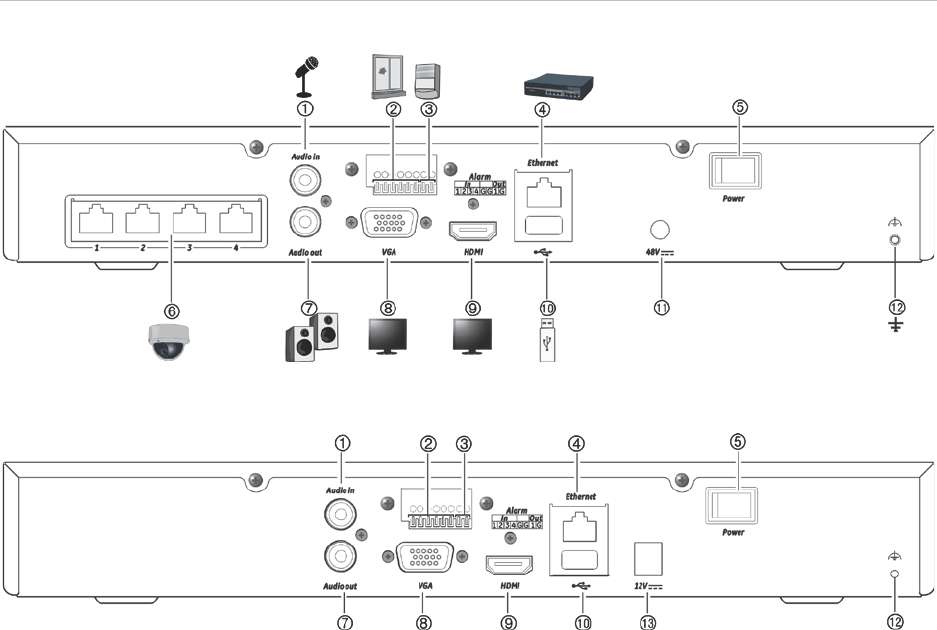
Figure 1: Back panel connections TVN 1104cS and TVN 1104c
TVN 1104cS:
TVN 1104c: (EMEA only)
1. Connect a microphone for bi-directional audio
(not recorded).
2. Connect up to four alarm inputs
3. Connect one alarm relay output.
4. Connect to a network.
5. Power switch (on/off).
6. Embedded PoE ports to connect IP cameras
(4).
7. Connect to speakers for audio output.
8. Connect to a VGA monitor.
9. Connect to an HDTV. The HDMI connection
supports both digital audio and video.
10. Connect to an optional USB 2.0 device such
as a mouse, CD/DVD burner or HDD.
11. Connect to the 48 VDC PSU (included)
(depending on model)
12. Connect to ground.
13. Connect to the 12 VDC PSU (included)
(depending on model).
Chapter 2: Physical installation
TruVision NVR 11 User Manual 11
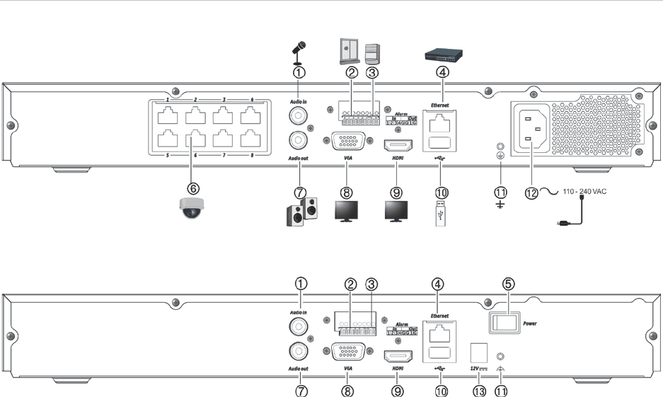
Figure 2: Back panel connections TVN 1108S and TVN 1108
TVN 1108S:
TVN 1108: (EMEA only)
1. Connect a microphone for bi-directional audio
(not recorded).
2. Connect up to four alarm inputs
3. Connect one alarm relay output.
4. Connect to a network.
5. Power switch (on/off).
6. Embedded PoE ports to connect IP cameras
(8).
7. Connect to speakers for audio output.
8. Connect to a VGA monitor.
9. Connect to an HDTV. The HDMI connection
supports both digital audio and video.
10. Connect to an optional USB 2.0 device such
as a mouse, CD/DVD burner or HDD.
11. Connect to ground.
12. Connect a power cord to the recorder
(included).
13. Connect to the 12 VDC PSU (included).
Chapter 2: Physical installation
12 TruVision NVR 11 User Manual
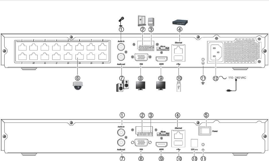
Figure 3: Back panel connections TVN 1116S and TVN 1116
TVN 1116S:
TVN 1116: (EMEA only)
1. Connect a microphone for bi-directional audio
(not recorded).
2. Connect up to four alarm inputs
3. Connect one alarm relay output.
4. Connect to a network.
5. Power switch (on/off).
6. Embedded PoE ports to connect IP cameras
(16).
7. Connect to speakers for audio output.
8. Connect to a VGA monitor.
9. Connect to an HDTV. The HDMI connection
supports both digital audio and video.
10. Connect to an optional USB 2.0 device such
as a mouse, CD/DVD burner or HDD.
11. Connect to ground.
12. Connect a power cord to the recorder
(included).
13. Connect to the 12 VDC PSU (included).
Monitor connections
The recorder supports up to 1920 × 1080 / 60 Hz resolution in VGA and up to 3840 x
2160 / 30 Hz in HDMI. The monitor resolution should be at least 1024 × 768. Adjust
your monitor accordingly to this resolution.
There is no event monitor for the 4-channel recorder. The VGA and HDMI monitors
both show the same image. When an event occurs, it appears in full-screen mode on
both monitors.
For the 8- and 16-channel recorders, the VGA and HDMI monitors can be used as the
main and event monitors.

Chapter 2: Physical installation
TruVision NVR 11 User Manual 13
Rack mounting
There is no rack mount kit for the recorder. The TVN 1108/TVN 1116 are rack
mountable using the rack mount ears delivered with the product. The four-channel
model is a desktop model and is not shipped with rack mount ears. See Figure 4 below.
Figure 4: Rack-mount installation
To install the rack ears:
1. Attach the two small front-rack mount ears (A) to the recorder (supplied).
2. Attach the recorder to the front rails (B) (screws not supplied).
14 TruVision NVR 11 User Manual
Chapter 3
Getting started
Powering on the recorder
Before starting the recorder, connect at least one monitor (VGA or HDMI). Otherwise,
you will not be able to see the user interface and operate the device.
The recorder auto-detects the video mode (PAL or NTSC) on startup.
It comes equipped with a universal power supply that will auto-sense 110/240 V,
60/50 Hz.
Note: It is recommended that an uninterruptible power supply (UPS) is used in
conjunction with the device.
To turn on the recorder:
Turn on the recorder using the power switch on the back panel. Once it is powered up,
the status LEDs on the front panel will light up.
To turn off the recorder:
1. In live view mode, right-click the mouse and click Menu. The main menu window
appears.
2. From the menu toolbar, click Shutdown.
3. In the Shutdown popup menu, select Shutdown. Click Yes to confirm shutdown.
You will be requested to enter the Admin password.
To reboot the recorder:
1. In live view mode, right-click the mouse and click Menu. The main menu window
appears.
2. Select the Shutdown icon.
3. In the Shutdown popup menu, select Reboot. Click Yes to confirm shutdown.
You will be requested to enter the Admin password.
Chapter 3: Getting started
TruVision NVR 11 User Manual 15
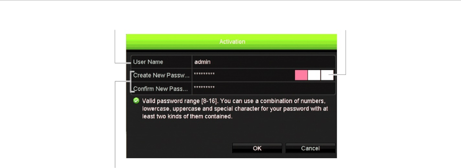
Activate the admin password
When you first start up the unit, the Activation window appears. You must define a high-
security admin password before you can access the unit. There is no default password
provided.
A message will appear on-screen when the unit has been activated.
Figure 5: Password activation window
User Name: It is always “admin”. It cannot be
changed. The bar showing password strength
Enter the new admin password and confirm it.
Tips on creating a strong password:
A valid password range must be between 8 and 16 characters. You can use a
combination of numbers, lower and upper case letters, and special characters : _ - ,
. * & @ / $ ? Space. The password must contain characters from at least two of
these groups.
The password is case-sensitive.
Do not use personal information or common words as a password.
Note: If you should forget your admin password, please contact Technical Support to
reactivate the unit with a new password.
Go to Chapter 16 “User management” on page 131 for further information on creating
user passwords.
Default network settings
The network settings are:
• IP address - 192.168.1.82
• Subnet mask - 255.255.255.0
• Gateway address - 192.168.1.1
• Ports:

Chapter 3: Getting started
16 TruVision NVR 11 User Manual
When using the browser:
RTSP port: 554
HTTP port: 80
When using TruNav:
RTSP port: 554
Server/Client software port: 8000
Go to “Using the web browser” on page 141 for further information.
The startup wizard
The recorder has an express installation wizard that lets you easily configure basic
recorder settings when first used. It configures all cameras to default settings. The
configuration of each camera and recorder can be customized as required.
By default the startup wizard will start once the recorder has loaded. It will walk you
through some of the more important settings of your recorder.
Any changes you make to a setup configuration page are saved when you exit the page
and return to the main wizard page.
Note: If you want to set up the recorder with default settings only, click Next in each
screen until the end.
To use the Startup wizard:
1. To launch the startup wizard without rebooting the device, go to Menu > Device
Management > General Settings and click ‘Start wizard Now’.
2. Select the preferred language for the system and resolution from the dropdown list
and then click Next.
3. Enable or disable the option to start the wizard automatically when the recorder is
turned on. Default is Enable. Click Next.
4. In each setup configuration page, enter the desired information and then click Next
to move to the next page. The setup configuration pages are:
Wizard setup pages Description
User configuration You can change the admin password and create additional
users.
You must enter an admin password. To change the Admin
password, select New Admin Password. Enter the new
password and confirm it. See “Activate the admin
password” on page 15 for tips on creating a strong
password.
Time and date configuration Select the desired time zone, date format, system time,
and system date.
If Daylight saving time (DST) is required, check Enable
DST and enter the desired summer and winter times.
Note: The system time and date are visible on screen.
However, they do not appear in recordings.

Chapter 3: Getting started
TruVision NVR 11 User Manual 17
Wizard setup pages Description
Network configuration Configure your network settings such as the NIC type, IP
address, subnet mask, and default gateway. Enter the
preferred DNS server address as well as the alternate one
to use.
HDD management The hard drives are initialized at the factory. However if
you wish to clear all data, click Initialize to initialize the
HDD.
Adding IP cameras There are two ways to add an IP camera to the recorder
system:
Manually: Under IP Camera Address/Domain enter the IP
address of the IP camera to be added. Select the
appropriate protocol, stream number, and management
port and then enter the user name and Admin password.
Click the Add button. Click Next to move to the next page.
Automatically: Click Search to find any available IP
cameras on the LAN. The search list will display all
supported IP cameras that are located on the LAN. Select
the desired IP cameras from the search results list. Click
Quick Add to add the selected cameras to the recorder
system without modifying the camera configuration.
Note: You do not need to search for PoE cameras. They
are automatically recognized when plugged in.
Recording Configure your default recording settings as required. The
settings apply to all cameras connected to the recorder.
Check the Constant Recording checkbox for the recorder
to record continuously all day. If left unchecked, the
recorder will not record. This is enabled by default.
Check the desired time lapse checkbox, TL-Hi or TL-Lo.
Default is TL-Hi.
To record motion detection events, check Event (Motion).
To record alarm events, check Alarm.
Note: You can configure the recording parameters of each
individual camera for the different recording schedules in
the recording menu.
5. When all the required changes have been entered, a summary page appears
showing all the settings.
Click Finish to exit the Wizard. The recorder is now ready to use.
For a description of the recorder main menu, see “Menu overview” on page 24.
18 TruVision NVR 11 User Manual
Chapter 4
Operating instructions
Controlling the recorder
There are several ways to control the recorder:
• Front panel control. See “The front panel description” below.
• Mouse control. See “Using the mouse” on page 21.
• IR remote control. See “Using the IR remote control” on page 22.
• TVK-800 keypad (from TVK-800 firmware version 1.2e). Please refer to the user
manual for more information.
• Software (TruVision Navigator, TVRMobile). See Chapter 18 “Using the web
browser” on page 141 for more information on using the web browser. Please refer
to the TruVision Navigator and TVRMobile user manuals for more information on
these tools.
You can use your preferred control method for any procedure, but in most cases we
describe procedures using the mouse. Optional control methods are given only when
they differ substantially from the mouse control methods.
The front panel description
The function buttons on the front panel control can be used to operate most, but not all,
of the main functions of the recorder. The LED indicators light up to alert you of various
conditions. The functions available can be limited by setting passwords. See Figure 6
on page 19 for more information.
Chapter 4: Operating instructions
TruVision NVR 11 User Manual 19
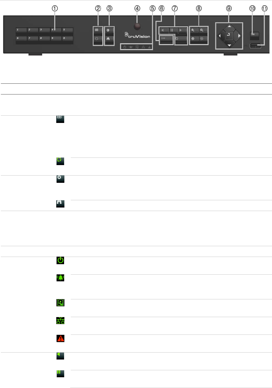
Figure 6: TVN 11 front panel (four-channel model shown)
The controls on the front panel include:
Table 1: Front panel elements
Name Description
1
. Channel buttons Switch between different cameras in live, PTZ control or playback modes.
Use the soft keyboard to enter numerals 0 to 9.
2
. Display
buttons Display: In multiview mode, toggle through the various multiviews (full, quad,
1+5, 1+7, 9 and 16).
In HDD information mode and user management mode delete a selected
item. In PTZ mode, delete a selected key point. In Log Search mode, display
the details of a log file in Log Search result.
Seq: In Live View mode, start/stop sequencing cameras on the current
monitor.
3
. Menu and
Search
buttons
Menu: Enter/exit the main menu.
Search: In live view, enter the advanced search menu.
4
. IR receiver Receiver for IR remote.
To connect the remote control to the recorder, press the Device button, enter
the device address, and press Enter. See “Using the IR remote control” on
page 22 for more information.
5
. Live button Live: Switch to live view mode.
6
. Status LEDs Power: A steady green light indicates the recorder is working correctly. Red
indicates a fault.
Event Alarm: A flashing red light indicates that there is a sensor Alarm In or
another alarm such as motion or tampering. No light indicates that there is no
alarm.
HDD: HDD indicator steady green when data is being read from or written to
the HDD. A steady red light indicates an HDD exception or error.
Tx/Rx: Steady green indicates a normal network connection. No light
indicates that it is not connected to a network.
Technical Alarm: A steady red light indicates that there is a technical alarm
from the recorder. No light indicates that there is no alarm.
7
. Playback
buttons Reverse: In live view mode, use to play back the earliest video. In playback
mode, playback a camera in the reverse direction.
Pause: In live view, freeze the last image of the live display for all active
cameras displayed. In playback mode, stop playback.
Chapter 4: Operating instructions
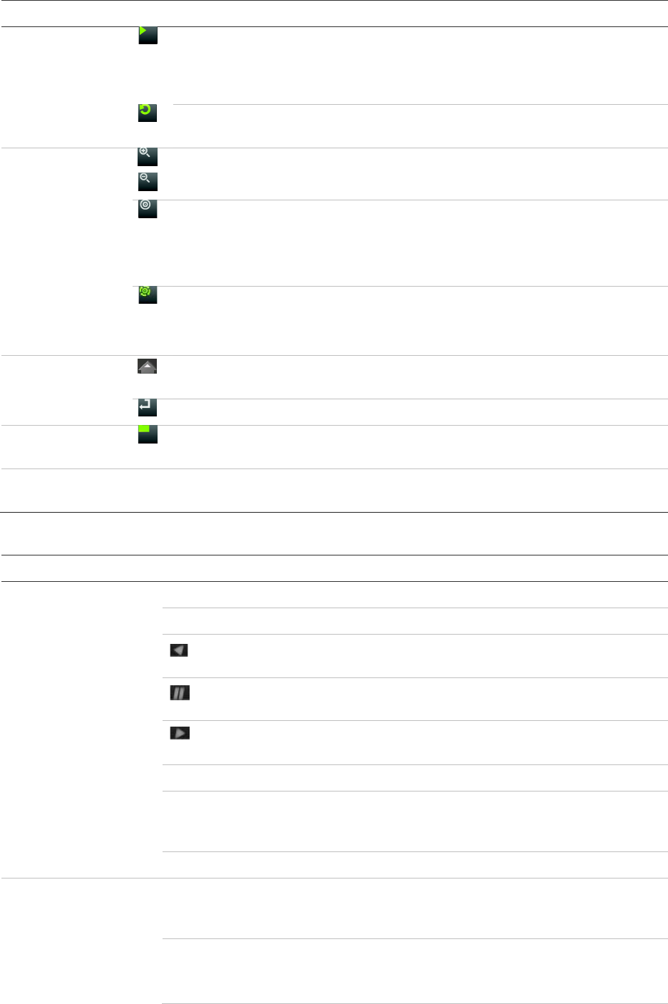
20 TruVision NVR 11 User Manual
Name Description
Play: In live view mode, play all day playback of the current camera (upper-
left video tile if in multiview mode). In playback mode, play back a camera in
the forward direction. In search mode, play back a selected video or view a
snapshot. In PTZ mode, do an auto tour.
Playback: In playback mode, start playing the current file. Starts at the
beginning of the file.
8
. PTZ buttons
Zoom +/-: In live view mode, playback mode, and PTZ control mode use this
button to zoom in and out. Also use them to navigate within menus.
Preset: In PTZ Control mode, press Preset and a numeric button to call the
specified preset.
Also use to edit holiday mode, video search mode, HDD selection mode, user
management mode, bookmark management, and bookmark search.
Tour: In PTZ Control mode, press Tour and a numeric button to call the
specified shadow tour.
Also use to scroll between calendar months and to navigate in a text field.
9
. Direction The DIRECTION buttons are used to navigate between different fields and
items in menus.
Enter button The ENTER button is used to confirm selection in any of the menu modes.
10
. Archive
button Press once to enter quick archive mode. Press twice to start archiving.
Indicator blinks green when data is being written to backup device.
11
. USB Interface Universal Serial Bus (USB) port for additional devices such as a USB mouse,
CD/DVD burner, or USB Hard Disk Drive (HDD).
Table 2: Front panel button functions by task
Task
Button
Button function
Live view mode
Direction Press to cycle through channels.
Enter Press to show the PTZ control toolbar.
Reverse Press to play the earliest video file of the current camera (upper-
left video tile if in multiview mode).
Pause Press to freeze the last image of the live display for all active
cameras displayed.
Play Press to play 24-hour playback of the current camera (upper-left
video tile if in multiview mode).
Live Press to switch to live view mode.
Seq Press to start/stop sequencing cameras on the current monitor.
Hold the Seq button for three seconds to start and stop
sequencing.
Menu Press to enter the main menu.
Playback mode
Direction The left and right buttons are used to speed up and slow down
recorded video. The up and down buttons are used to jump
recorded video forwards or backwards by 30 s.
Enter Press the button to pause the video. Press again to restart the
video.
In single-frame Playback mode, press to advance the video by a
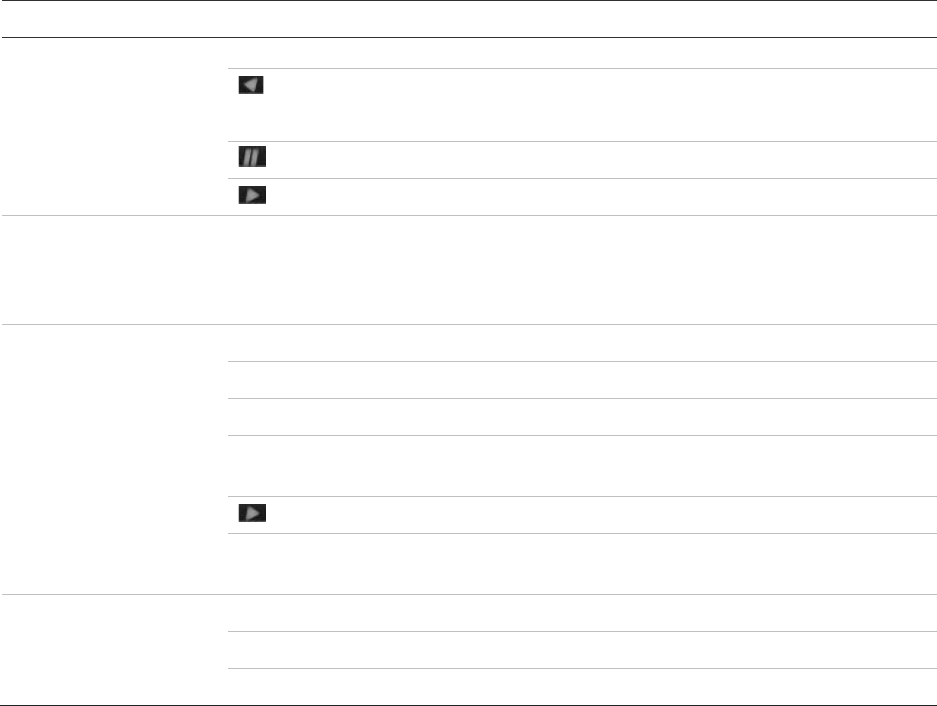
Chapter 4: Operating instructions
TruVision NVR 11 User Manual 21
Task
Button
Button function
single frame.
Reverse Press to play back a camera in reverse direction.
In Picture Playback mode, view pictures in reverse direction.
Pause In Playback mode, stop playback.
Play In Playback mode, play back a camera in the forward direction.
Pause mode
Direction The left and right buttons are used to jump recorded video
forwards or backwards by one frame. The up and down buttons
are used to jump recorded video forwards or backwards by one
second.
PTZ control
mode Direction Press to control the movement of the PTZ camera.
Zoom +/- Press to zoom in and out.
Preset Press Preset and a numeric button to call the specified preset.
Tour Press Tour and a numeric button to call the specified shadow
tour.
Play Press to do an auto tour.
Display Press to delete a selected key point from the PTZ Setting >
More Settings> Tour > Key Point list.
Menu navigation
Direction Press to navigate between different fields and items in menus.
Menu Enter/exit the main menu.
Enter Press to confirm the selection in any of the menu modes.
Using the mouse
The USB mouse provided with the recorder can be used to operate all the functions of
the unit, unlike the front panel which has limited functionality. The USB mouse lets you
navigate and make changes to settings in the user interface.
Connect the mouse to the recorder by plugging the mouse USB connector into the USB
port on the back panel or the front panel. The mouse is immediately operational and the
pointer should appear.
Note: Use a USB 2.0 mouse.
Move the pointer to a command, option, or button on a window. Click the left mouse
button to enter or confirm a selection.
You can purchase a spare mouse by ordering part number TVR-MOUSE-1.
See Table 3 below for a description of the mouse buttons.

Chapter 4: Operating instructions
22 TruVision NVR 11 User Manual
Table 3: Mouse buttons
Item
Description
Left button
Single-Click Live view: Select a camera to display the live view toolbar.
Menu: Select a component of a menu, such as a button or
an input field. This is similar to pressing the Enter button
on the remote/front panel controls.
Double-Click Live view: Switch between single screen and multi-screen
mode in live/ playback mode.
Click and Drag Live view: Drag channel/time bar.
PTZ control: Adjust pan, tilt and zoom.
Tamperproof, privacy masking and motion detection
functions: Select the target area.
Digital zoom-in: Drag and select target area.
Right button
Single-Click Live view: Display menu.
Menu: Exit the current menu and return to higher level.
Scroll
-wheel Scroll Up Live view: Return to the previous window.
Menu: Move the selection to the previous item.
Scroll Down Live view: Move to the next window.
Menu: Move the selection to the next item.
Using the IR remote control
The recorder is supplied with an infrared (IR) remote control unit. Like the mouse, it can
be used to operate all of the main functions of the unit.
The IR remote control can be programmed with a unique device ID address so that the
controller will only be able to communicate with recorders with that address. No
programming is necessary if using a single recorder.
The device ID address only applies when using a remote control and not when using a
keypad.
You can purchase a replacement remote control by ordering part number TVR-
REMOTE-1.
Chapter 4: Operating instructions
TruVision NVR 11 User Manual 23
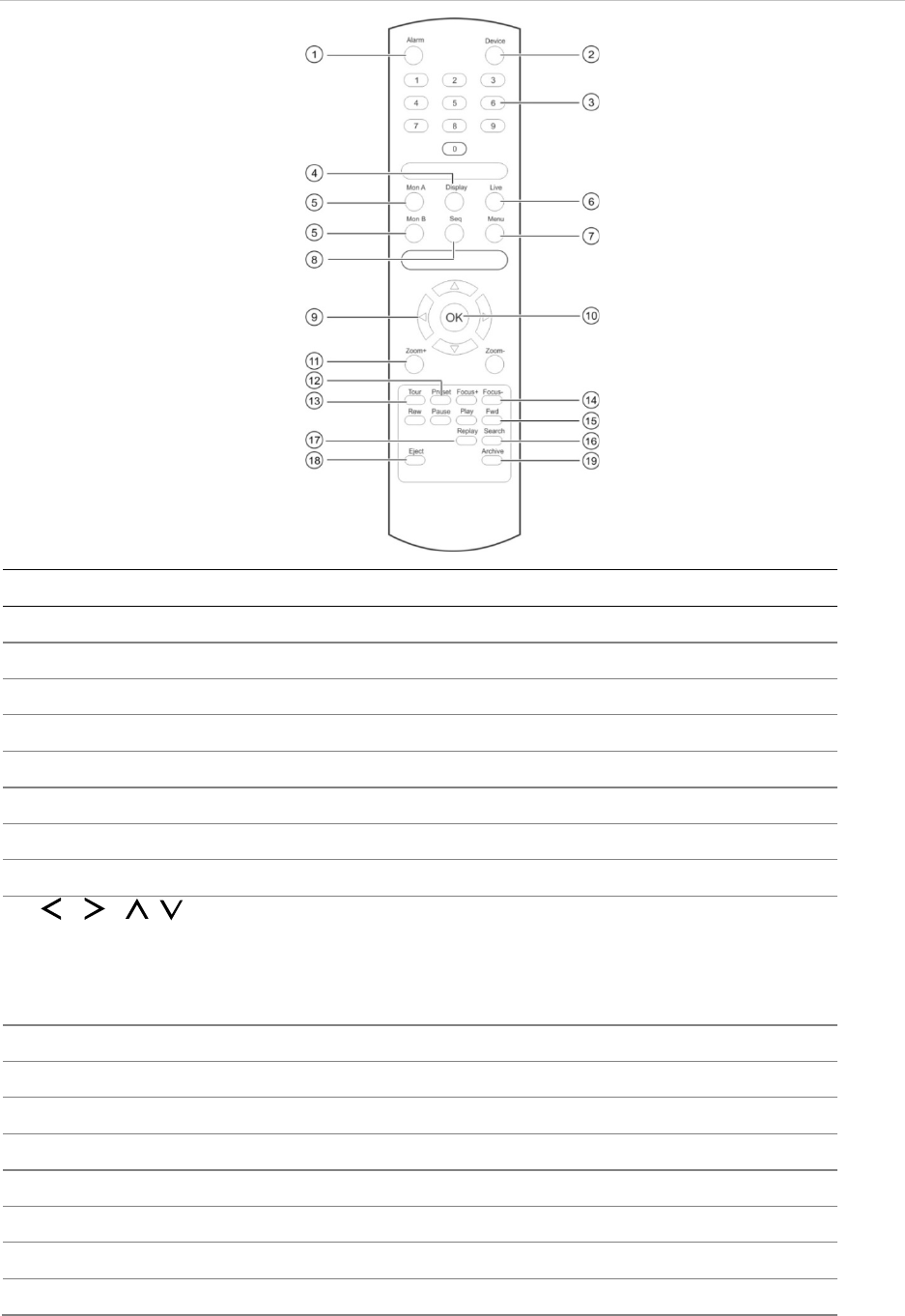
Figure 7: IR remote control
Item
Description
1
. Alarm
Acknowledge an alarm.
2
. Device
Enable/disable the IR remote control to control the recorder.
3
. Numeric buttons
Select a camera, and enter a number in a menu option.
4
. Display
Switch between the different multiview formats.
5
. Mon A and Mon B
Switch between monitors A and B.
6
. Live
Return to live view mode.
7
. Menu
Activate the main menu.
8
. Seq
Start /stop sequencing.
9
. , , ,
In Menu mode: Use left or right
arrow buttons to select and up or down
arrow buttons to edit entry.
In PTZ mode: Use to control PTZ.
In Playback mode: Use to control playback speed.
10
. OK
Confirm selection.
11
. Zoom + and -
Use to control zoom of
camera lens.
12
. Preset
Enter preprogrammed three
-digit code to call up a preset.
13
. Tour
Enter preprogrammed three
-digit code to call up shadow tour.
14
. Focus + and -
Use to control focus of camera lens
.
15
. Playback control
Use to control playback (Rewind, Pause, Play, and Fast Forward).
16
. Search
Open the Search menu.
17
. Replay
Play back
the selected file from the beginning.

Chapter 4: Operating instructions
24 TruVision NVR 11 User Manual
Item
Description
18
. Eject
Eject the CD or DVD disk.
Does not apply to TVN 11.
19
. Archive
Press once to enter quick archive mode. Press twice to start archiving.
Aim the remote control at the IR receiver located at the front of the unit to test
operation.
To change the address of the remote control to the recorder:
1. Press the Menu button on the front panel or right-click the mouse and select the
Menu button. The default display menu window appears.
2. Click Device Management > General Settings.
3. Check the remote control ID value. The default value is 255. This device address is
valid for all IR controls.
Note: The recorder will respond to any remote control that has an address between
1 and 255.
4. On the remote control press the Device button.
5. Enter the device address value. It must be the same as that on the recorder.
6. Press the OK button on the remote control.
To place batteries into the IR remote control:
1. Remove the battery cover.
2. Insert the batteries. Make sure that the positive (+) and negative (−) poles are
correctly placed.
3. Replace the battery cover.
Troubleshooting the remote control
If the IR remote control is not functioning properly, perform the following tests:
• Check the battery polarity.
• Check the remaining charge in the batteries.
• Check that the IR remote control sensor is not masked.
If the problem still exists, please contact your administrator.
Menu overview
The recorder has an intuitive structure that allows you to configure the unit’s
parameters quickly and efficiently. Each command icon displays a window that lets you
edit a group of settings. Most menus are available only to system administrators.
Chapter 4: Operating instructions
TruVision NVR 11 User Manual 25
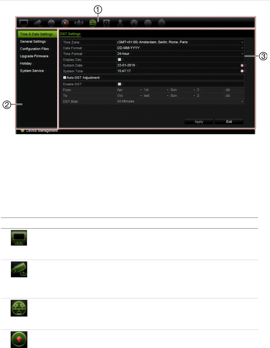
The window is divided into three sections. The currently selected command icon and
submenu item are highlighted in green. See Figure 8 below.
You must be in live view mode to access the main menu.
Figure 8: Menu structure
1. Menu toolbar: Setup options available for the selected menu function. Move the mouse over a
command icon and click to select it. See Table 4 below for a description of the icons.
2. Submenu panel: Submenus for the selected menu function are displayed. Click an item to select it.
3. Setup menu: All the details for the selected submenu are displayed. Click a field to make changes.
Note: See Table 2 on page 19 for the description on how to access the menu options
using the front panel.
Table 4: Description of the menu toolbar icons
Icon Name Description
Display Settings
Configures display settings including video format, resolution,
video output interface, dwell time, multiview format, and
display status icons. See Chapter 9 “Display settings” on
page 62.
Camera Setup
Configures IP cameras, snapshot resolution and quality,
camera settings including OSD, motion detection setup,
privacy masking, tampering setup, restricted access setup,
VCA setup, PTZ presets and shadow tours, and V-stream
encoding. See Chapter 10 “Camera setup” on page 66
Network Settings
Configures standard network settings including IP address,
email notifications, PPPoE setup, DDNS setup, and
advanced network settings. See the Chapter 11 “Network
settings” on page 88.
Recording
Configures recording settings including instant playback
duration, recording schedule, and manual recording. See
Chapter 12 “Recording” on page 99.

Chapter 4: Operating instructions
26 TruVision NVR 11 User Manual
Icon Name Description
Alarm and Event
Setup
Configures alarm settings including alarm input, alarm output,
manual trigger, buzzer settings, alarm notifications, video
loss, alarm host setup, as well as intrusion panel and zone
setup (intrusion integration). See Chapter 13 “Alarm and
event setup” on page 104.
Device Management
Configures system settings including system date and time,
DST, language, menu timeout, import/export config files,
firmware upgrade, holiday schedules. See Chapter 14
“Device management” on page 119.
Storage Management
Configures HDD information, storage mode, S.M.A.R.T.
settings, and bad sector detection. See Chapter 15 “Storage
management” on page 126.
User Management
Configures users and their passwords as well as access
privileges. See Chapter 16 “User management” on page 131.
System Information
Displays device information, camera setup information,
recording setup information, alarm inputs information, alarm
outputs information, network information, HDD information,
and log search. See Chapter 17 “System information” on
page 135.
Help
Provides reference information to the various toolbars,
menus, and keys within the interface.
Shutdown
Provides access to logout, reboot, and shutdown options.
See “Powering on the recorder” on page 14.
To access the main menu:
1. In live view, press the Menu button on the remote control or front panel.
- Or -
Right-click the mouse and select Menu from the pop-up menu.
The main menu window appears. The Display Settings window appears by default.
2. Click the required menu icon to display its submenu options. Modify the
configuration parameters as required.
3. Click Apply to save the settings.
4. Click Exit to leave the menu setup and return to live view.
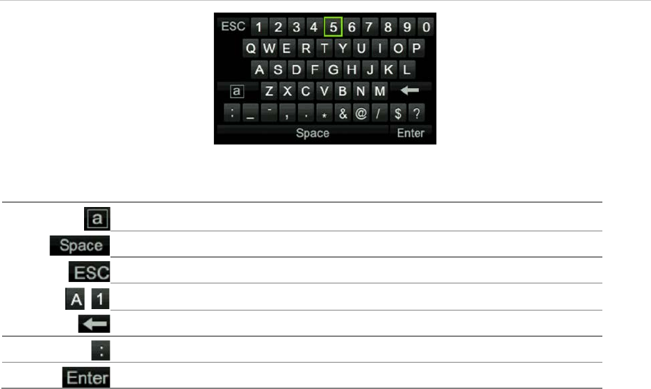
The soft keyboard
A keyboard will appear on-screen when you need to enter characters in a window
option. Click a key to input that character.
Chapter 4: Operating instructions
TruVision NVR 11 User Manual 27
Figure 9: The soft keyboard
Description of the keys in the soft keyboard:
Switch to lowercase/upperc
ase
Space
Exit the soft keyboard
Alphanumeric characters
Backspace
Punctuation
Confirm selection
Exiting the main menu
Press the Menu button on the front panel to exit the current menu window and return to
live view, or click Exit in a main menu.
28 TruVision NVR 11 User Manual
Chapter 5
Live view
Description of live view
Live view mode is the normal operating mode of the unit where you watch live images
from the cameras. The recorder automatically enters into live view mode once powered
up. On the monitor you can see whether a recording is in progress and, if set up to do
so, the current date and time, as well as the camera name.
Status information
Information on the system and camera status is displayed as icons on the main and
auxiliary monitors. The camera status icons are shown for each camera. Each icon
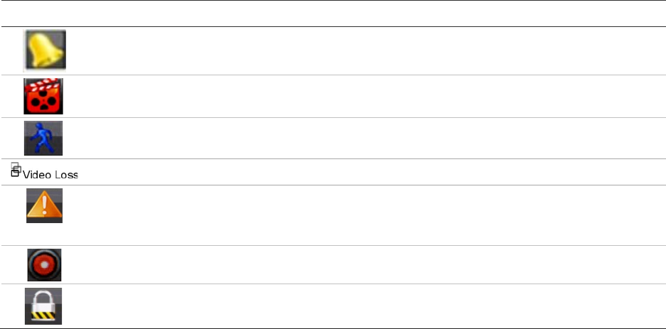
represents information on a specific item. These icons include:
Table 5: Description of the on-screen status icons
Icon
Description
Indicates an alarm.
Indicates that a camera channel is being recorded.
Indicates a motion detection event.
Indicates a video loss event.
Indicates alarm and system event notifications. Clicking the event hint icon opens the
Alarm Center window that lists all the alarm and event notifications. See “Event
notification” on page 107 for more information.
Indicates manual recording.
Indicates that live view is locked from the front panel. Mouse actions are still allowed.
The recorder can display more than one icon at the same time.
Chapter 5: Live view
TruVision NVR 11 User Manual 29
The system status is displayed on the front panel by the status LEDs.
Video output
The recorder has one HDMI and one VGA port.
The recorder automatically checks the monitor outputs used on startup. For the 8- and
16-channel recorders, the HDMI and VGA monitors can be set as the main or event
monitor.
The event monitor is used to display detected events such as motion.
Note: There is no event monitor for the four-channel recorder. When an event occurs, it
appears in full-screen mode on both monitors.
Only one monitor can be controlled at a time.
Live view mouse menu
Many features of live view can be quickly accessed by placing the cursor on a live
image and clicking the right-button of the mouse. The mouse menu appears (see
Figure 14 below).
Note: The 4-channel recorder has the same mouse menu except there is no monitor
selection option.
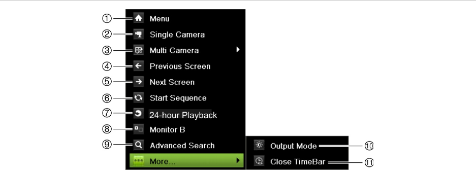
Figure 10: The mouse menu (8- and 16-channel recorders shown)
See Table 6 on page 30.

Chapter 5: Live view
30 TruVision NVR 11 User Manual
Table 6: Mouse menu
Name Description
1
. Menu Enter the Main menu.
This option is not available from monitor B.
2
. Single Camera Switch to a full-screen view for the selected camera from the
dropdown list. See “Single and multiview display mode” on page 31
for more information.
3
. Multi Camera Switch between the different multiview options from the dropdown
list. See “Single and multiview display ” on page 31 for more
information.
4
. Previous Screen Displays the previous camera.
5
. Next Screen Displays the next camera.
6
. Start Sequence Turn on sequence mode. The window automatically sequences
between cameras. To set up the sequence dwell time, go to Menu >
Display Settings > Display > Sequence Dwell Time and select a
value.
7
. 24-hour Playback Playback the recorded video of the selected day from the selected
camera. The current day is selected by default. See “24-hour
playback” on page 45 for more information.
8
. Monitor B 8- and 16-channel recorders:
Switch between monitors A (main) and B (event).
4-channel recorder:
Not available.
9
. Advanced Search Enter the advanced video search menu. See “
Advanced search video
menu” on page 46 for more information.
10
. Output Mode Select Standard, Bright, Soft, or Vivid mode to display.
11
. Close Time Bar Open/close the time bar.
Table 7: Mouse menu for monitor B (event monitor) (8- and 16-channel recorders only)
Name Description
1
.
Single Camera Switch to a full-screen view for the selected camera from the
dropdown list.
2
. Multi Camera Switch between the different multiview options from the dropdown
list.
3
. Previous Screen Displays the previous camera.
4
. Next Screen Displays the next camera.
5
. 24-hour Playback Playback the recorded video of the selected day from the selected
camera. The current day is selected by default. See “24-hour
playback” on page 45 for more information.
6
. Monitor A Switch between monitors A (main) and B (event).

Chapter 5: Live view
TruVision NVR 11 User Manual 31
Single and multiview display mode
The recorder has single and multiview formats. The number of multiview display modes
available depends on the recorder model.
Single view display
format Press the numeric button on the front panel to switch to the corresponding
camera display. For example, press button 4 to view camera 4.
-Or-
Right-click the mouse and select Single Camera from the menu. Select the
required camera from the list.
Multiple view display
format Press the Display button on the front panel to cycle through different display
formats.
-Or-
Right-click the mouse and select Multi Camera from the menu. Select the
desired multiview display layout.
Sequencing cameras
The sequencing feature allows a camera to be displayed briefly on screen, before
advancing to the next camera in the sequence list. Sequencing can only be done in
single-view display mode.
The default sequence displays each camera in numerical order. However, each camera
on a recorder can have a pre-programmed dwell time and sequence order. See
“Layout” on page 64 for more information.
Note: You must first set up the sequence dwell time under the Display menu. The dwell
time must not be set to zero for sequencing to function.
Sequencing cameras using the front panel:
Select the camera where you want to start sequencing. Press the Seq button on
the front panel to start sequencing. Press it again to stop sequencing.
Sequencing cameras using the mouse:
Select the camera where you want to start sequencing. Right-click the mouse and
select Start Sequence to start the sequencing. Right-click again and select Stop
Sequence to stop sequencing.
Live view toolbar
The live view toolbar in live view lets you quickly access regularly used commands.
Position the cursor over a video image and left- click the mouse. The toolbar appears
(see Figure 11 on page 32).
Chapter 5: Live view
32 TruVision NVR 11 User Manual
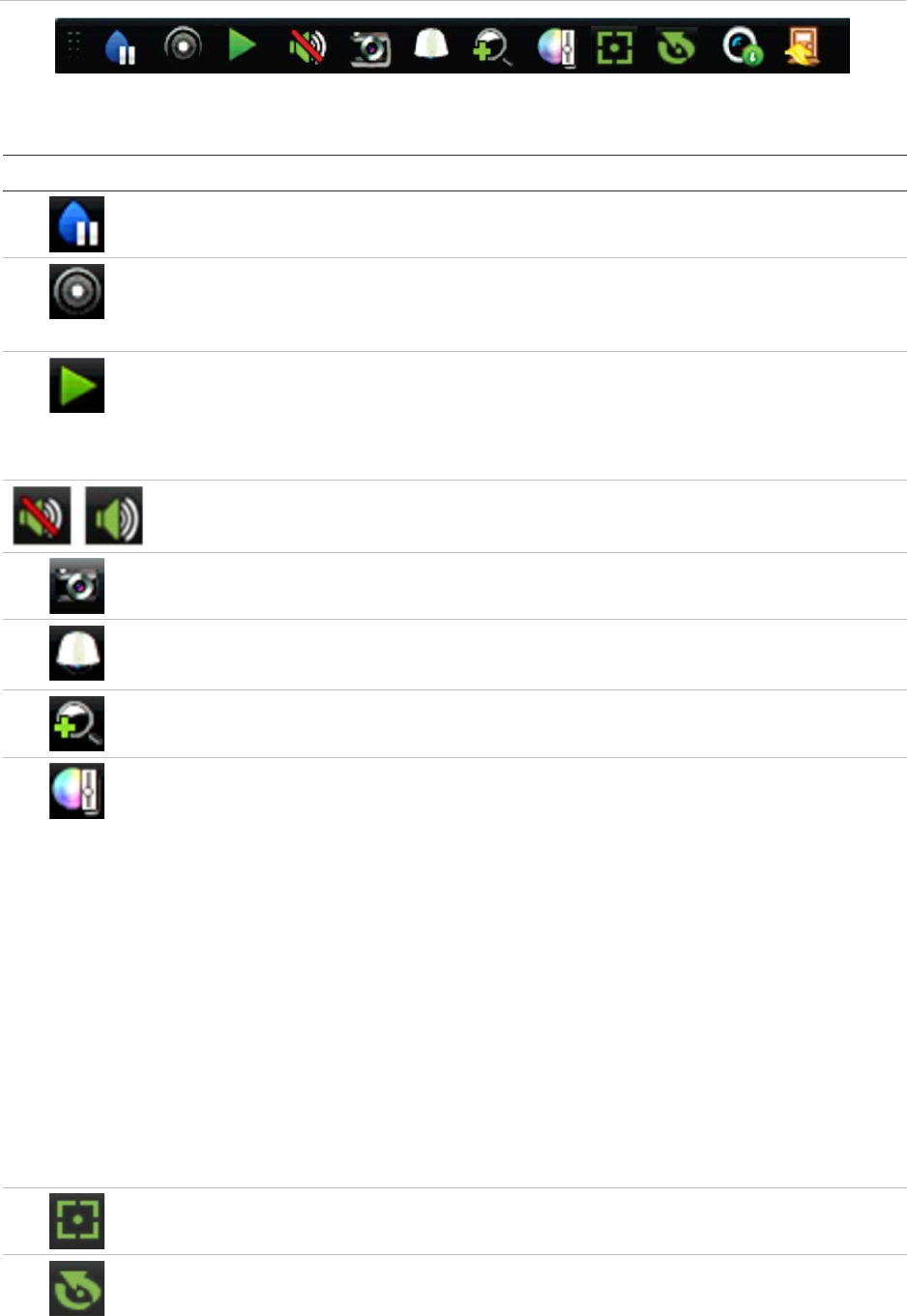
Figure 11: Live view toolbar
Table 8: Description of the live view toolbar icons
Icon Description
Pause: Freeze the live image of the selected camera. Although the image pauses, time
and date information does not. The system clock continues to run.
Start Manual Recording: Start/stop manual recording.
The icon is red when manual recording is enabled. See “Recording schedule” on page
99 for information on setting up this function.
Instant Playback: Playback the recorded video from the last five minutes. If no
recording is found, then there was no recording made in the last five minutes.
Click the icon and select the desired camera. Click OK.
See “Modify the instant playback duration” on page 42 For more information.
Audio On: Enable/Disable audio output. The audio option must already have been
setup in the Display Settings menu.
Snapshot: Capture a snapshot of a video image. The image is saved on the unit. See
“By snapshots” on page 37 for more information.
PTZ Control: Enter PTZ control mode.
See “PTZ preset and tours” on page 33 for more information.
Digital Zoom: Enter digital zoom. See “Digital zoom” on page 33 for further information.
Image Settings: Enter the image settings menu to modify the image lighting levels.
There are two options:
Preset Mode: These are preconfigured image lighting levels. Select one of the four
options depending on current lighting conditions:
- Standard: Use in standard lighting situations.
- Indoor: Use indoors.
- Dim Light: Use when the light level is low.
- Outdoor: Use when outdoors. The contrast and saturation values are high.
Customize: Modify brightness, contrast, saturation, and hue values. Click Restore to
restore image settings to previous values.
Click Restore to restore image settings to previous values. Click Default to return to
default values.
These settings can also be modified from the Camera Setup > Image menu (see page
“Image settings” on page 75.
Auxiliary Focus: Automatically focus the camera lens for the sharpest picture.
Lens Initialization: Initialize the lens of a camera with a motorized lens, such as PTZ
or IP cameras. This function helps to maintain lens focus accuracy over prolong periods
of time.
Chapter 5: Live view
TruVision NVR 11 User Manual 33
Icon Description
Stream Information: Display the real-time frame rate, bit rate, resolution and video
compression.
Close Toolbar: Close the toolbar.
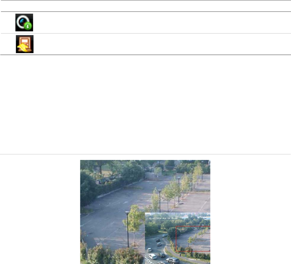
Digital zoom
You can easily zoom in or out of a camera image in live view mode and playback using
the digital zoom command. The zoom command magnifies the camera image four
times. See Figure 12 below.
Figure 12: Digital zoom window
To quickly zoom in/out on a camera image:
1. Left-click the mouse on the desired camera image. The live view toolbar appears.
2. Click the digital-zoom icon. The digital view window appears in single-view display
mode for the selected camera.
3. Left-click the mouse and drag the red square to the area of interest, or press the
arrow buttons on the front panel to position the red square. The selected area is
magnified.
4. To exit digital zoom, right-click the mouse.
PTZ preset and tours
When in live view you can quickly call up the list of existing presets, preset tours and
shadow tours by using the front panel, remote control, mouse and keypad.
Chapter 5: Live view
34 TruVision NVR 11 User Manual
Front panel Press Enter. PTZ control panel appears.
Mouse Left-click the mouse on the desired camera image. The live view toolbar appears.
Click the PTZ control icon to enter PTZ mode. The PTZ control panel appears.
Remote control Press the OK button. The PTZ control panel appears.
Keypad Press the Enter button on the keypad.
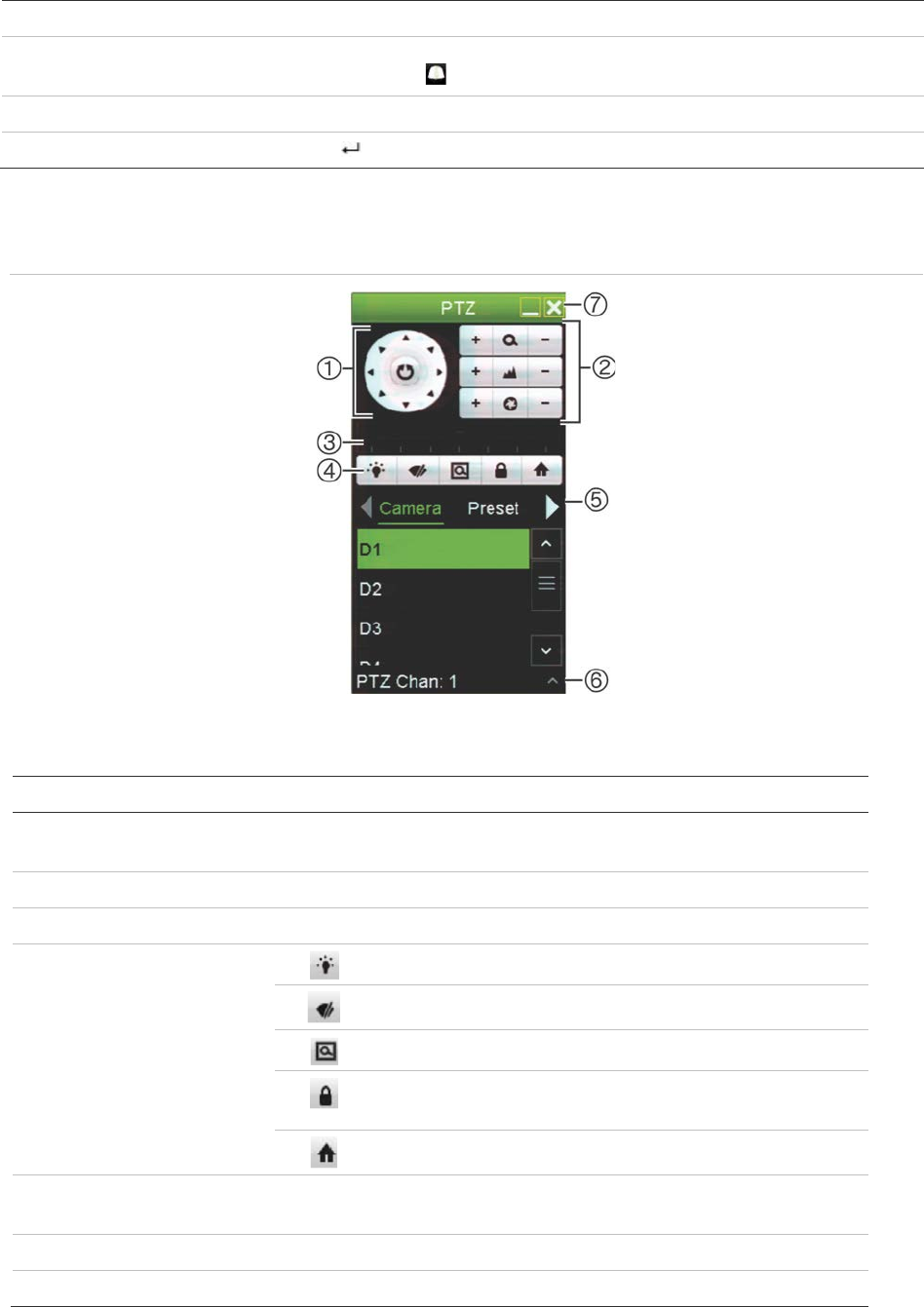
See Figure 13 below for a description of the PTZ control panel.
Figure 13: PTZ control panel
Table 9: Description of the PTZ control panel
Name Description
1.
Directional pad/auto-
scan buttons Controls the movements and directions of the PTZ. The center
button is used to start auto-pan by the PTZ dome camera.
2.
Zoom, focus, and iris Adjusts zoom, focus and iris.
3.
PTZ movement Adjusts the speed of PTZ movement.
4.
Toolbar
Turns on/off camera light (when available).
Turns on/off camera wiper.
Zoom area.
Centers the PTZ dome camera image. This command is
not supported on all PTZ dome cameras.
Jumps to the home position.
5.
Select PTZ command Displays the desired function from the scroll bar: Camera, Preset,
Preset Tour or Shadow Tour.
6.
Show/Hide Show/hide the preset, preset tour and shadow tour lists
7
. Exit Exits the PTZ control panel.

Chapter 5: Live view
TruVision NVR 11 User Manual 35
To call up a preset:
1. In live view, left-click the mouse and select the PTZ control icon in the quick access
toolbar. The PTZ control panel appears. Select the desired camera from the toolbar.
– Or –
On the front panel, select the desired camera and press (Enter) to call up the
PTZ control panel.
2. Scroll the PTZ control panel to Preset and double-click the desired preset from the
list. The camera immediately jumps to the preset position.
To call up a preset tour:
1. In live view, left-click the mouse and select the PTZ control icon in the live view
toolbar. The PTZ control panel appears. Select the desired camera from the toolbar.
– Or –
On the front panel, select the desired camera and press (Enter) to call up the
PTZ control panel.
2. Scroll the toolbar to Tour and double-click the desired preset tour from the list. The
camera immediately carries out the preset tour movement.
To call up a shadow tour:
1. In live view left-click the mouse and select the PTZ Control icon in the live view
toolbar. The PTZ control panel appears. Select the desired camera from the toolbar.
– Or –
On the front panel, select the desired camera and press Enter to call up the live
view toolbar. The PTZ control panel appears.
2. Scroll the PTZ control panel to Shadow Tour and double-click the shadow tour from
the list. The camera immediately carries out the shadow tour movement.
36 TruVision NVR 11 User Manual
Chapter 6
Searching files
This chapter describes how to search and playback recorded videos as well as search
them by time, events, bookmarks, and snapshots.
Advanced search video menu
You can easily search and play back recorded videos by time and date, events,
bookmarks, and snapshots.
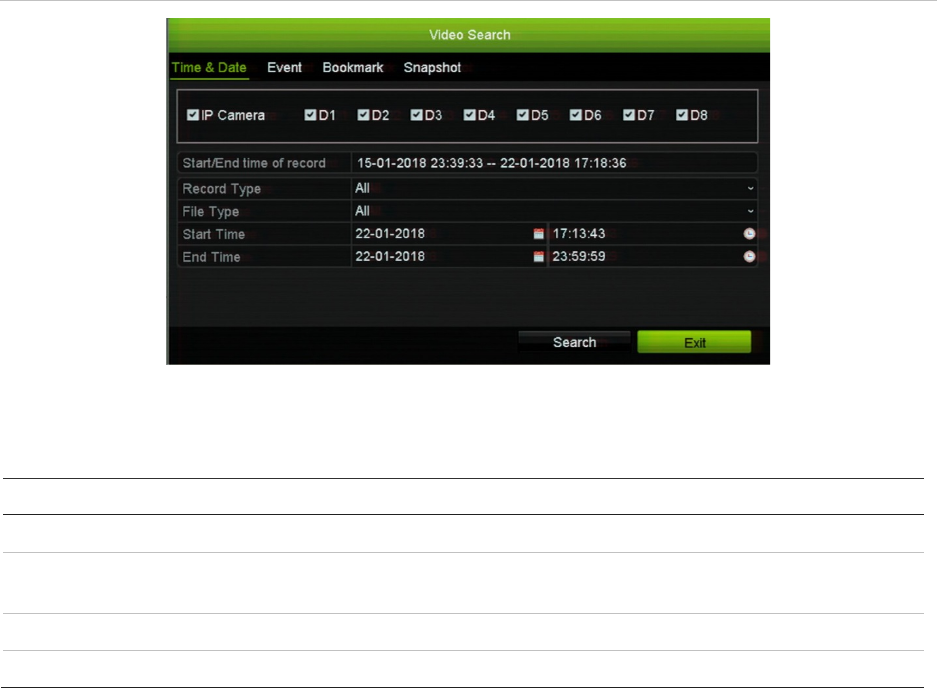
Figure 14: The Advanced Search menu
The Search window has four submenus that allow you to carry out different searches by
theme:
Search type
Description
Time and date
Search all video by time and date of recording.
Event
Search only event recorded files. Files can be searched by alarm inputs,
motion detection, intrusion panel alarms, or intelligent alarms.
Bookmark
Search for recorded files with bookmarks.
Snapshot
Search for snapshots.
Chapter 6: Searching files
TruVision NVR 11 User Manual 37
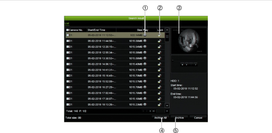
Search results
A search will usually produce a list of files, which may extend to several pages. The
files are listed by date and time. The most recent file is listed first. You can then select a
file to play it back in the playback viewer. See Figure 15 on page 37 for an example of a
search.
You can view a full-screen playback of a search result. Press the Play button for a
desired file in its results row. The 24-hr playback of the file starts in full screen mode
(see Figure 16 on page 43).
A recording file can be up to 1GB in size.
Only one file can be played back at a time.
Figure 15: Example of a search result list
1. Click to play back the selected video in full
screen mode.
2. Click to lock recording to prevent it from being
overwritten.
3. Playback viewer
4. Archive selected files.
5. Archive all files.
Search recordings
By time and date
You can search recorded video by time and video type, such as continuous recordings,
motion, alarms, and all recordings.

Chapter 6: Searching files
38 TruVision NVR 11 User Manual
To search video files by time and date:
1. In live view, right-click the mouse on the desired video pane and select Advanced
Search. The Video Search menu appears.
– Or –
On the front panel, click the Search icon.
2. In the Search menu, click the “Time & Date” tab.
3. Select the desired cameras, record type, file type as well as start and end times of
the recording.
4. Click Search. The list of search results appears.
5. Click Play on the desired file to play back the search results in the playback
viewer.
By events
You can search recorded video by event type: motion, VCA alarms, alarm inputs, and
intrusion alarms.
To search for events:
1. In live view, right-click the mouse on the desired video pane and select Advanced
Search. The Video Search menu appears.
– Or –
Click the Search icon on the front panel.
2. In the Search menu, click the “Event” tab.
3. Select the desired event type as well as start and end times of the recording.
4. Select the desired alarm inputs or channels.
If you selected “Intelligent Alarm” as the event type, select the required IP cameras.
5. Click Search. The list of search results appears.
6. Select the desired video from the list.
7. In the search results window, you can:
- Click Play to playback the footage
- Click Archive to archive results
Note: You can modify the pre- and post-play periods of a recording.
By bookmarked recordings
For information on creating bookmarks, see “Create bookmarks” on page 54.

Chapter 6: Searching files
TruVision NVR 11 User Manual 39
To search for a bookmark:
1. In live view, right-click the mouse on the desired video pane and select Advanced
Search. The Video Search menu appears.
– Or –
Click the Search icon on the front panel.
2. In the Search menu, click the “Bookmark” tab.
3. Select the desired cameras as well as start and end times of the recording to be
searched. Also select the type of bookmark to be searched, “Bookmark keyword” or
“All”.
If searching for customized bookmarks, enter a keyword from the bookmark name.
Click Search. The list of bookmarks appears.
4. Select the desired bookmark from the list.
5. Select a bookmark and do one of the following:
Click the Edit button to edit a bookmark’s name.
- Or -
Click the Delete button to delete a bookmark.
- Or -
Click the Play button to play back a bookmark.
By snapshots
You can search for snapshots of recorded video. See “Live view mouse menu” on page
29 on how to create snapshots.
To search for snapshots:
1. In live view, right-click the mouse on the desired video pane and select Advanced
Search. The Video Search menu appears.
– Or –
Click the Search icon on the front panel.
2. In the Search menu, click the “Snapshot” tab.
3. Select the desired cameras as well as start and end times of the recording to be
searched.
4. Click Search. The list of snapshots appears.
5. Select a snapshot to see it in the thumbnail window. Click its Play button to see
it in full-screen mode.
6. When in full-screen mode, move the cursor to the right edge of the window to see
the complete list of snapshots found in the search. Click their Play buttons to see
them in full-screen mode.
Chapter 6: Searching files
40 TruVision NVR 11 User Manual
7. To see a slideshow of all the snapshots found, click the or buttons on the
snapshot toolbar to sequence forwards or backwards through the shots.
Log search
You can open video footage from the results of a log search. Refer to “Search the
system log” on page 138 for more information.

TruVision NVR 11 User Manual 41
Chapter 7
Playback functionality
The recorder lets you quickly locate and play back recorded video. There are three
ways to play back video:
Instant playback of the most recently recorded video
24-hour playback of one day’s recorded video
Search video by specific time, events, motion detection, bookmarks, or snapshots
(see Chapter 6 “Searching files” on page 36 for further information)
The recorder continues to record the live view from a camera while simultaneously
playing back video on that camera display. You must have the access privilege to play
back recordings (see “Customize a user’s access privileges” on page 132 for more
information).
Instant playback
Use the live view toolbar to perform instant replay of a predefined period (default time is
five minutes). This can be useful to review an event that has just happened. Only one
camera at a time can be selected.
You can modify the playback period in the Playback Duration menu. See page 42 for
further information.
To instantly replay recorded video:
1. In live view mode, left-click the mouse on the desired camera image. The live view
toolbar appears. Click the Instant Playback icon .
Note: You will be asked to enter the Admin password.
2. Click the Channel icon and select the desired camera from the drop-down list.
Click OK.
Playback starts immediately. The Instant Playback scroll bar appears under the
selected camera.
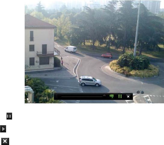
Chapter 7: Playback functionality
42 TruVision NVR 11 User Manual
3. Click Pause on the toolbar to pause playback.
Click Play to restart playback.
Click Stop to stop playback and return to live view.
Modify the instant playback duration
The live view toolbar in live view lets you quickly playback recorded video for a
preprogrammed period. You can easily change this preprogrammed time period. See
page 31 for more information on the live view toolbar.
To modify the preprogrammed time of this instant playback, go to Recording >
General. Select one of the times from the drop-down list (5, 10, 20, or 30 minutes) and
click Apply. Default is 5 minutes.
Overview of the 24-hour playback view
It is easy to manage playback from the 24-hour playback window.
The playback video can be set up to display a time/date stamp for evidentiary purposes
(see “Camera OSD” on page 74).
The playback windows for 24-hour playback and for the results of a search are
different.
24-hour playback is in full-screen mode
A video file of a search result is only visible in the playback viewer in the search
results window. See “Search results” on page 37 for more information
Chapter 7: Playback functionality
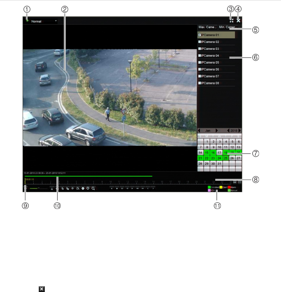
TruVision NVR 11 User Manual 43
Figure 16: 24-hour playback window
1. Playback mode: Select one of seven
playback modes to view: Normal, Event,
Bookmark, Smart, Sub-periods, External
File, or Snapshot. See “24-hour playback”
on page 45 for more information.
2. Playback viewer.
3. Full screen.
4. Exit 24-hour playback recording.
Click Exit or right-click the mouse to
return to live view.
5. Quick camera select:
Max. Camera for Playback: From the
camera list, automatically selects the first
16 cameras with recordings.
Min. Camera for Playback: From the
camera list, automatically select the first
camera with recordings.
Note: Cameras can also be selected
manually. The maximum number of
cameras that can be selected is 16,
whether selected automatically or
manually.
6. Camera panel. Select the cameras for
playback. Move the mouse over the area to
display the list of cameras available.
7. Calendar panel.
White: No recordings.
Green/Yellow/Red/Pale green/Magenta:
Recordings available on the recorder.
8. Playback control toolbar. See Figure 17 on
page 44 for more information.
9. Time bar: Time of actual playback. This is only
displayed in 24-hour playback.
10. 24-hour playback bar: This bar displays how
much of the 24-hour period has been recorded.
11. Recording type: Description of the color coding
of recording types that appear in the playback
progress bar. Green indicates continual
recording. Yellow indicates motion recording.
Red indicates alarm recording. Pale green
indicates manual recording. Magenta indicates
VCA recording.
Chapter 7: Playback functionality
44 TruVision NVR 11 User Manual
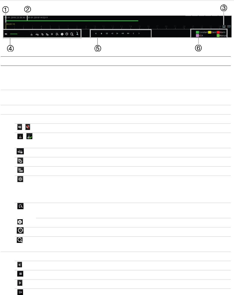
The 24-hour playback control toolbar
It is easy to manually control playback using the playback control toolbar. See
Figure 17 below.
Note: The playback control toolbar does not appear for instant playback.
Figure 17: 24-hour playback control toolbar
Description
1
. Timeline: Allows you to jump forwards or backwards in time. The timeline moves left (oldest
video) to right (newest video). Click a location on it for where you want playback to start.
In 24-hour playback, the cursor shows the actual time.
2
. Playback bar: This bar displays the playback recording. It indicates in color the type of
recording. Constant recording is shown in the example above.
3
. Zoom in and out of the recording.
4
. Audio and video control toolbar:
/ Audio on/off.
/ Start/stop a video clip during playback. Sections of a recording can be saved to an
external storage device.
Lock a file during playback.
Add default bookmark.
Add customized bookmark.
File management.
Click to see the list of video clips, snapshots, locked files, bookmarks and their times.
The video clips, playback captures and locked files can be archived. Bookmarks can
be renamed and deleted.
Digital zoom.
Click to enter the digital zoom function. Right click the mouse to exit.
Archive files.
Modify the forward and reverse skip times.
Call up the Search window to search for recorded video files by time & date, events,
bookmarks, and snapshots.
5
. Playback control toolbar:
Reverse play the recording. Click again to pause.
Stop playback. Time displayed is 00:00:00.
Play recording.
Fast forward playback by the configured skip time (default is 30 seconds).
Chapter 7: Playback functionality
TruVision NVR 11 User Manual 45
Description
Reverse playback by the configured skip time (default is 30 seconds).
Decrease playback speed: Options available are: ½ speed, ¼ speed, 1/8 speed,
single frame.
Increase playback speed. Options available are: 2X speed, 4X speed, 8X speed, 32X
speed.
Play previous file/day/event recording.
Play next file/day/event recording in the search result.
6
. Recording type: Description of the color coding of the five recording types that appear in the
playback progress bar. Green indicates continuous recording. Yellow indicates motion
detection. Red indicates alarm recording. Pale green indicates manual recording. Magenta
indicates VCA recording.
24-hour playback
Use this option to access one day of video recordings for the selected camera.
Playback starts at midnight and runs for the 24-hour period. 24-hour playback is shown
in full-screen view. See Figure 17 on page 44 for a description of the playback control
toolbar.
• Using the mouse:
1. In live view mode right-click the mouse on the desired camera image. In the mouse
toolbar, click 24-hour Playback.
The playback screen appears. By default, the camera is in full-screen mode.
2. To select more than one camera for synchronous playback or to select playback
from a different day, move the mouse to the right edge of the screen. The camera
list and calendar are displayed. Check the desired cameras and/or another day. Up
to 8 cameras can be selected for 8/16 channel recorders and up to 4 cameras for
the 4-channel recorder.
Playback starts immediately you have selected the camera and times.
Note: A message appears if there are no recordings found during this period.
3. Use the playback control toolbar to manually control playback.
4. Click Exit or right-click the mouse to return to live view.
– Or –
Right-click the mouse and click Exit from the mouse menu to return to the previous
window.
Chapter 7: Playback functionality
46 TruVision NVR 11 User Manual
• Using the front panel:
1. Select the camera for playback and press the Play button. Playback from the
selected camera starts immediately.
Note: Synchronous playback is only available using the mouse. If live view was
showing multiview, only the camera in the top-left channel on screen will be played
back.
2. To select a different camera for playback, press the numerical button of the desired
camera.
3. Press Live to return to live view.
24-hour playback modes
You can select one of seven different 24-hour playback modes (see item 1 in Figure 17
on page 44). They are:
Playback mode Description
Normal Play back recordings from the selected cameras of the selected day.
Select the desired cameras and day to play back. Playback starts
immediately.
You can select all the playback toolbar options.
Event Play back recorded selected VCA, alarm inputs or motion events. See
“Event playback” on page 47 for more information.
Bookmark Select the desired cameras and time period to search for bookmarks. Enter
the desired keyword to search for a specific file name, if required. Click
Search. The list of bookmarks appears. Change the pre and post-play
times, if required.
Click Play for the desired bookmark to play back.
Click the Exit button to exit the playback of the selected bookmark and do
another search, or click the Search icon to open the Search window
and select the Bookmark tab.
Note: You can only search for a bookmark by file name in the 24-hour
playback mode.
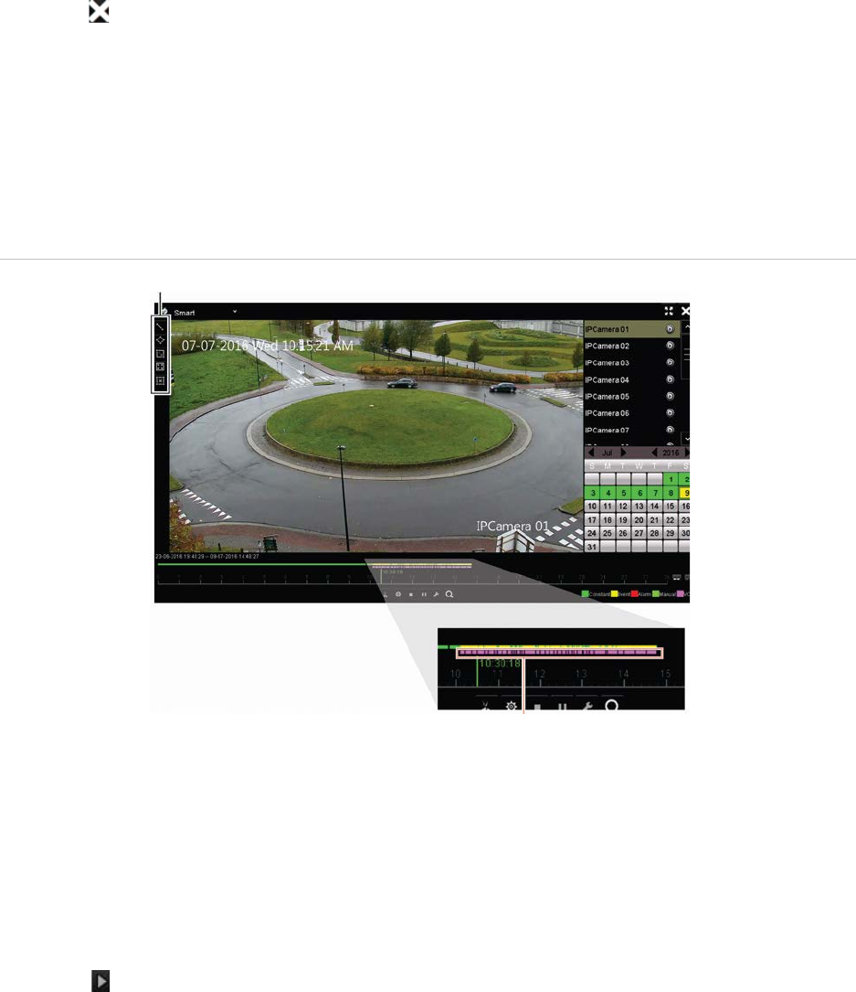
Smart This feature lets you selectively playback the parts of a recording with VCA
and motion events and skip over video that does not have such events.
See “Smart playback” on page 48” on page 47 for more information.
Sub-periods This feature lets you see simultaneously the 24-hour playback recording
for a selected camera split over several consecutive time periods. See
“Split-screen playback” on page 50.
Select the desired camera and number of split screens. Playback starts
immediately.
External file Import a file to play back.
Insert the storage device, such as a USB flash drive, in the recorder and
select a video file to play back.
Chapter 7: Playback functionality
TruVision NVR 11 User Manual 47
Playback mode Description
Snapshot Select the desired cameras and the time period. Click Search. The list of
snapshots appears. Click Play to see the desired snapshot.
To search again, click the Search icon to open the Search window and
select the Snapshot tab.
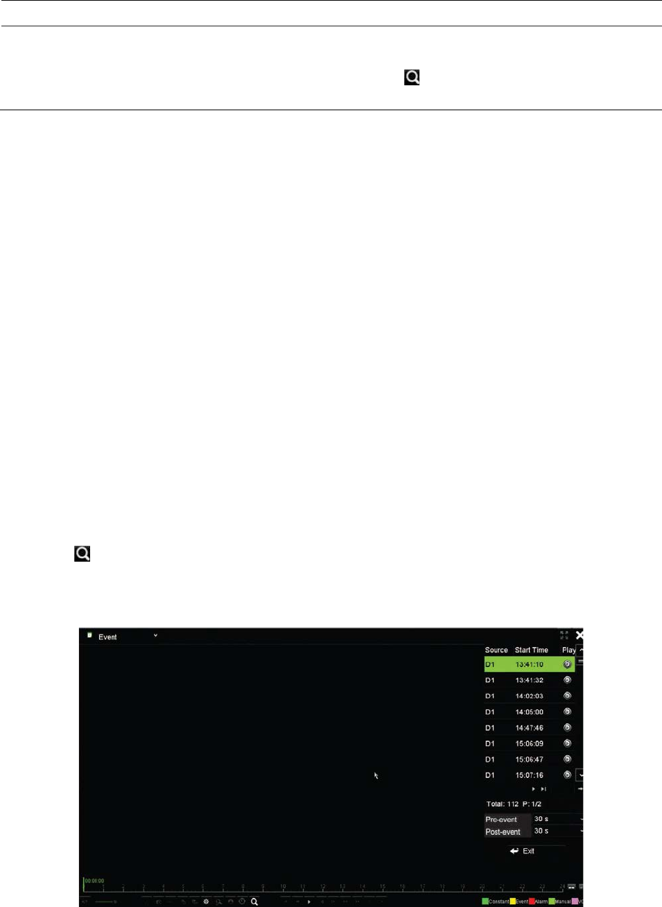
Event playback
This feature lets you selectively playback VCA, alarm input and motion events.
To do an event playback:
1. In 24-hour playback mode, select Event from the drop-down list on the upper left-
corner of the window.
2. Select the type of event to search for from the right-hand side of the window: Alarm
Input, Motion, or VCA Alarm.
If you select VCA Alarm, select the type of VCA alarm under Minor Type. Also
select the desired cameras to search.
If you select Alarm Input, select the desired alarm inputs from the list displayed.
If you select Motion, select the desired cameras to search.
Note: Motion detection must be enabled in order to use this function. See “Motion
detection” on page 76 for information.
3. Select the start and end dates and times for the event search.
4. Click Search to searching for the desired events.
The results are listed on the right side of the window. Each individual recorded event
is listed. They are collectively not shown on the playback toolbar.
5. Select the desired pre and post-event times (between 5 and 600 seconds). Default
time is 30 seconds.
Chapter 7: Playback functionality
48 TruVision NVR 11 User Manual
Note: These pre and post-event times are independent to the times set for camera
recordings under Camera Setup > Camera Recordings Settings. If you are only
recording events, the default pre and post-event times are determined by the values
set up under Camera Setup > Camera Recordings Settings. Default is 5 seconds.
6. Click the desired camera recording to play back. Its time bar also appears on the
playback toolbar.
7. Click Exit to stop the play back and return to the previous window. You can do
another search selection.
8. Click to exit playback and return to live view.
Smart playback
This feature lets you selectively playback the parts of a recording with VCA and motion
events and skip over video that does not have such events. The Smart Playback mode
analyses the video for VCA and motion events and marks them. See Figure 18 below.
Figure 18: Example of a smart playback recording
Smart event options
Smart bar showing all smart events found
For more information on VCA events, go to “VCA setup” on page 80.
To do a smart playback:
1. In playback mode, select Smart from the drop-down list on the upper left-corner of
the window.
2. Select a camera and date from the calendar on the right-hand side of the window.
3. Click Play to start playing the recording.
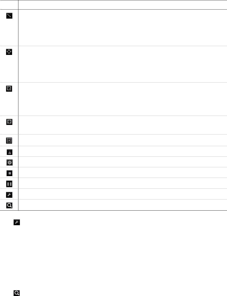
Chapter 7: Playback functionality
TruVision NVR 11 User Manual 49
4. Select the rules and areas to do a smart search for VCA or motion events in the
recording.
Icon Description
Cross line detection: This is used to detect people, vehicles and objects crossing a pre-
defined line or an area on-screen. If someone or an object crosses the line, the time of the
event is shown on the Smart bar.
Click the icon and then click on the image to indicate the start and end points of the line. If
you want to change the line position, re-click the icon and draw the line again.
Intrusion detection: This is used to detect when intrusion occurs. If someone enters the
selected area, the time of the event is shown on the Smart bar.
Click the icon and then click on the image the four points on the image to set the
quadrilateral area for intrusion detection. Only one area can be set. If you want to change
the detection area position, re-click the icon and draw the area again.
Motion detection: This is used to detect motion in a selected area.
Click the icon and then drag the mouse to draw the motion detection area.
Note: For IP cameras, you must enable motion detection in order to use this feature. For
analog/HD-TVI cameras, you do not need to enable motion detection.
Motion detection: This is used to detect motion over the whole image.
Click the icon. By default, the whole image is selected as the detection area.
Clear all areas selected.
Start and stop video clipping.
File management for video clips.
Stop playback.
Start or pause playback.
Smart settings.
Search matched video files.
5. Click Set and select the settings for the smart search:
Skip non-related video: Video that does not have selected events will not be
played.
Play non-related video: Set the speed to play the video with no selected events.
Play related video: Set the speed to play the video with selected events.
Pre-play(s): Set the pre-playback period. Default is 5 seconds.
Post-play(s): Set the post-playback period. Default is 5 seconds.
6. Click Search to search and play back video with the matched events, which are
shown in the Smart bar.
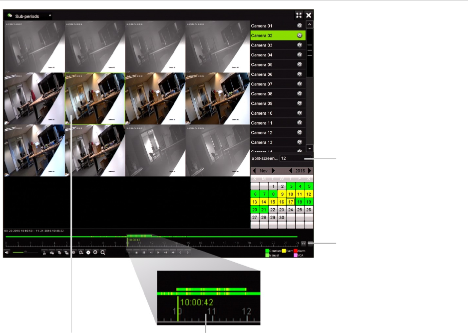
Chapter 7: Playback functionality
50 TruVision NVR 11 User Manual
Split-screen playback
This feature lets you see simultaneously the 24-hour playback recording for a selected
camera split over several consecutive time periods.
You can display the recording between four and 16 split screens. The recording is split
into equals time periods depending on the number of split screens selected. See
Figure 19 below.
Figure 19: Example of split-screen playback
Select the number of split
screens
Zoom In and Zoom Out
buttons for the playback
bar
Selected split screen Playback bar of the selected split screen
To do a split-screen playback:
1. In playback mode, select Sub-periods from the drop-down list on the upper left-
corner of the window.
2. Select a camera and date from the calendar on the right-hand side of the window.
3. In the Split-screen drop-down list, select the desired number of split screens. Up to
16 screens can be selected. Default is 3 screens.
The split screens immediately appear.
4. Click the desired screen to see the playback bar of that sub-period.
5. Click the Zoom In and Zoom Out buttons to focus in and out of the playback bar.

Chapter 7: Playback functionality
TruVision NVR 11 User Manual 51
6. Double-click the selected screen to see the playback at full-screen. Double-click
again to see the screen without the playback bar and camera list. Double-click again
to return to the split-screen mode.
7. You can do video clips, bookmarks and lock files of a split-screen playback.
8. Click to exit playback and return to live view.
Playback speed and skip time
Use the direction buttons on the front panel to modify the playback speed, and to jump
forwards or backwards.
The default skip time is 30 seconds, which can be easily changed.
To change the playback speed:
From the front panel:
Press the left and right buttons to speed up and slow down recorded video.
From the playback window using the mouse:
Click and to speed up and slow down recorded video.
To set the playback skip time:
1. In playback mode, click to open the pop-up Skip Time Settings menu.
2. Select a skip time between 10 and 300 seconds for forward and backward skip
times. The default skip time is 30 seconds. Click OK.
To skip forwards or backwards during playback:
From the front panel:
Press the up and down buttons to jump recorded video forwards and backwards by a
set skip time.
From the playback window using the mouse:
Click and to jump recorded video forwards and backwards by a set skip time.
— Or —
Click a location on the timeline for where you want playback to start.
Play back frame-by-frame
You can play back a selected video at different speeds. This allows you to carefully
examine an event frame-by-frame as it happens.
The current frame rate is shown on the right of the playback control toolbar.

Chapter 7: Playback functionality
52 TruVision NVR 11 User Manual
To play back frame-by-frame:
• Using a mouse:
1. In playback mode, click the Speed Down button in the playback control toolbar
until the speed changes to single frame.
2. Click the Pause button to advance the video frame by frame.
• Using the front panel:
1. In playback mode move the left direction button to left to scroll down through the
speed changes until single frame.
2. Press Enter to advance the video frame by frame.
Play back an archived file
You can play back an archived file on your backup device using TruVision Player.
However, you can also play back a file archived on your backup device using the 24-
hour playback mode.
To play back an archived file:
1. In 24-hour playback mode, select External File from the drop-down list on the upper
left-corner of the window.
2. Select the backup device and the desired file type to play back.
3. Position the mouse over a file to see the file name.
The name includes the recording date and time. For example, the recording
A0_TVN11_2018O117162916.mp4 was archived January 17, 2018, at 16:29:16
(24-hour time format).
4. Click the Play button or double-click the desired file to play it.
5. Click Exit to return to the previous window.
View a snapshot
You can view saved snapshots using the Search function. You can also view saved
snapshots using the 24-hour playback mode.
To play back a snapshot:
1. In 24-hour playback mode, select Snapshot from the drop-down list on the upper
left-corner of the window.
2. Select the camera(s) as well as the start and end times to search for snapshots.
3. Click Search. The list of snapshots found is listed.

Chapter 7: Playback functionality
TruVision NVR 11 User Manual 53
4. Click Play to see the desired snapshot.
5. Click Exit to return to the previous window.
Digital zoom in playback
You can zoom in on an image during playback to see it in greater detail. There are two
ways to perform digital zoom in playback.
To digitally zoom-in during playback:
1. In playback mode, click the time on the toolbar for the video that you want to view.
2. Click the Digital Zoom icon in the playback control toolbar.
The playback control toolbar disappears. The digital zoom window appears.
3. Left-click the mouse and drag the red square in the digital zoom window to the area
of interest. The selected area is magnified.
4. Right-click the mouse to quit digital zoom mode and return to full-screen playback
mode. The playback control toolbar reappears.
Create video clips
You can save important scenes in a recorded file for later reference by creating video
clips of selected portions of the file during playback. When an intruder, for example,
crosses in front of several cameras you can save the video clip of the intruder’s path
across these cameras in a single file.
Note: This feature is only available using the mouse.
To create video clips during playback:
1. Open the desired 24-hour playback window.
2. Click the playback timeline where you want the video clip to start and click the Start
Clipping button.
3. Click the playback timeline where you want the video clip to stop and click the End
Clipping button.
4. Repeat for additional clips.
5. Click the File Management button and click the Video Clips tab to see the list of
video clips saved. You cannot play them back.
To archive video clips, see “Archive video clips and locked files” on page 59”.
6. Click Cancel to return to 24-hour playback window.

Chapter 7: Playback functionality
54 TruVision NVR 11 User Manual
7. Click Exit to return to live view. If you have not saved the video clips, a pop-up
screen will ask you if you want to save them. If you answer Yes, the File
Management window will appear so that you can archive the files.
Create bookmarks
You can bookmark the important scenes in a recorded file for later reference.
Bookmarks flag the start of a scene. Up to 64 bookmarks can be saved in a video file.
There are two types of bookmarks:
• Default bookmark : All default bookmarks have the same generic name,
“BOOKMARK”.
• Customized bookmark : The bookmark is given a name for easy identification.
The same name can be used for several bookmarks.
You can search both types.
To create a bookmark:
1. Open the desired 24-hour playback window.
2. Click the playback timeline where you want the bookmark to be. The green time bar
jumps to this position. Click the button for the type of bookmark you want and enter
the bookmark name, if required.
3. Click the File Management button and click the Bookmark tab to see the list of
bookmarks saved. The name of a bookmark can be edited. A bookmark can also be
deleted.
To archive locked files, see “Archive video clips and locked files” on page 59”.
4. Click Cancel to return to the 24-hour playback window. Click Exit to return to live
view.
Lock playback files
You can lock recorded files during playback so they cannot be overwritten later on. In
multichannel playback using this Lock File function will lock all the recorded files for the
playback channels.
Note: Locking too many files will reduce the storage capacity of the recorder.
To lock during playback:
1. In 24-hour playback mode, click the Lock File button on the playback control
toolbar to lock the current recording file.
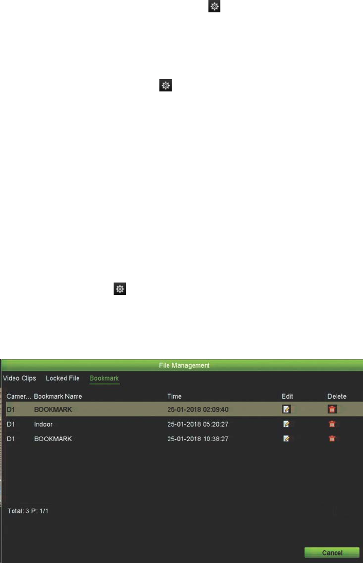
Chapter 7: Playback functionality
TruVision NVR 11 User Manual 55
2. To see the list of locked files saved, click the File Management button and in the
File Management window, select the Locked File tab. The list of locked files is
shown.
To unlock a locked file
1. In 24-hour playback mode, click the File Management button and in the File
Management window, select the Locked File tab. The list of locked files is shown.
2. Click the lock symbol of the desired file to unlock. The file is no longer protected.
Manage playback files
You can manage the video clips, locked recordings, and bookmarks created during 24-
hour playback and save them on a backup device. However, you cannot use this
function to manage snapshots.
To archive video clips, locked files and bookmarks:
1. In playback mode, click the File Management button. The File Management
window appears.
2. Select the tab for the files you want to manage: Video Clips, Locked File, or
Bookmarks.
3. Insert your backup device into the recorder.
4. Select the files you want to archive and click Archive or Archive All. The files are
saved.
56 TruVision NVR 11 User Manual
Chapter 8
Archiving files
Archive recorded files on an external device such as USB flash drive, USB HDDs or a
DVD burner. You must be in live view to archive video. Access to archive commands
may require a password.
Before starting to archive files, ensure that you have the backup device connected to
the recorder. It is detected automatically by the recorder.
Note: The recorder supports USB DVD and USB HD on the front and back USB ports.
Archive files
There are two ways to archive files:
Quick Archive button: Quick archive lets you archive recorded files quickly by using
the Archive button on the front panel. The recorder then downloads all the recorded
files on the unit to fill the available memory space on the media. This option is not
available via the mouse.
Search Results window: In the search results window there is an “Archive” button.
Click it to bring you to the archive window of the selected video in the search result.
See “Archive files from search results” on page 57 for more information.
TruVision Player
Use the standard file player software, TruVision Player, to play back the archived video
on your PC. It is included with the TVN 11.
Quick Archive
To archive recorded video using Quick Archive:
1. Insert the backup device into the recorder.

Chapter 8: Archiving files
TruVision NVR 11 User Manual 57
If using a USB memory drive, insert the device into the USB port on the front panel.
If more than one media type is found, the USB device takes precedence over the
others.
2. Press the Archive button on the front panel to open the Quick Archive window.
3. Select the files you want to archive.
4. Click Start or press Archive on the front panel again. The unit starts to download
the selected files to the backup device.
Note: A message will appear if there is a capacity limitation on the backup device.
A message will appear to confirm when the download is complete.
Archive files from search results
You can insert a mini-USB hub to the USB port to attach a mouse for navigation or a
USB drive for archiving. However, the unit may not support all types of USB hubs.
The Archive options available may depend on the type of backup device selected.
Archive window
After searching for all the recordings from selected parameters and cameras using
Advanced Search, the results are listed in the Search window. When you select the
desired files to archive and click the Archive or Archive All buttons, the Archive
window appears (see Figure 20 on page 58).
The Archive window lists all the files currently on your backup device. The window
shows the free space available on the backup device. You can also delete files from the
device and search by type of files present. Files cannot be played back from the
Archive window.
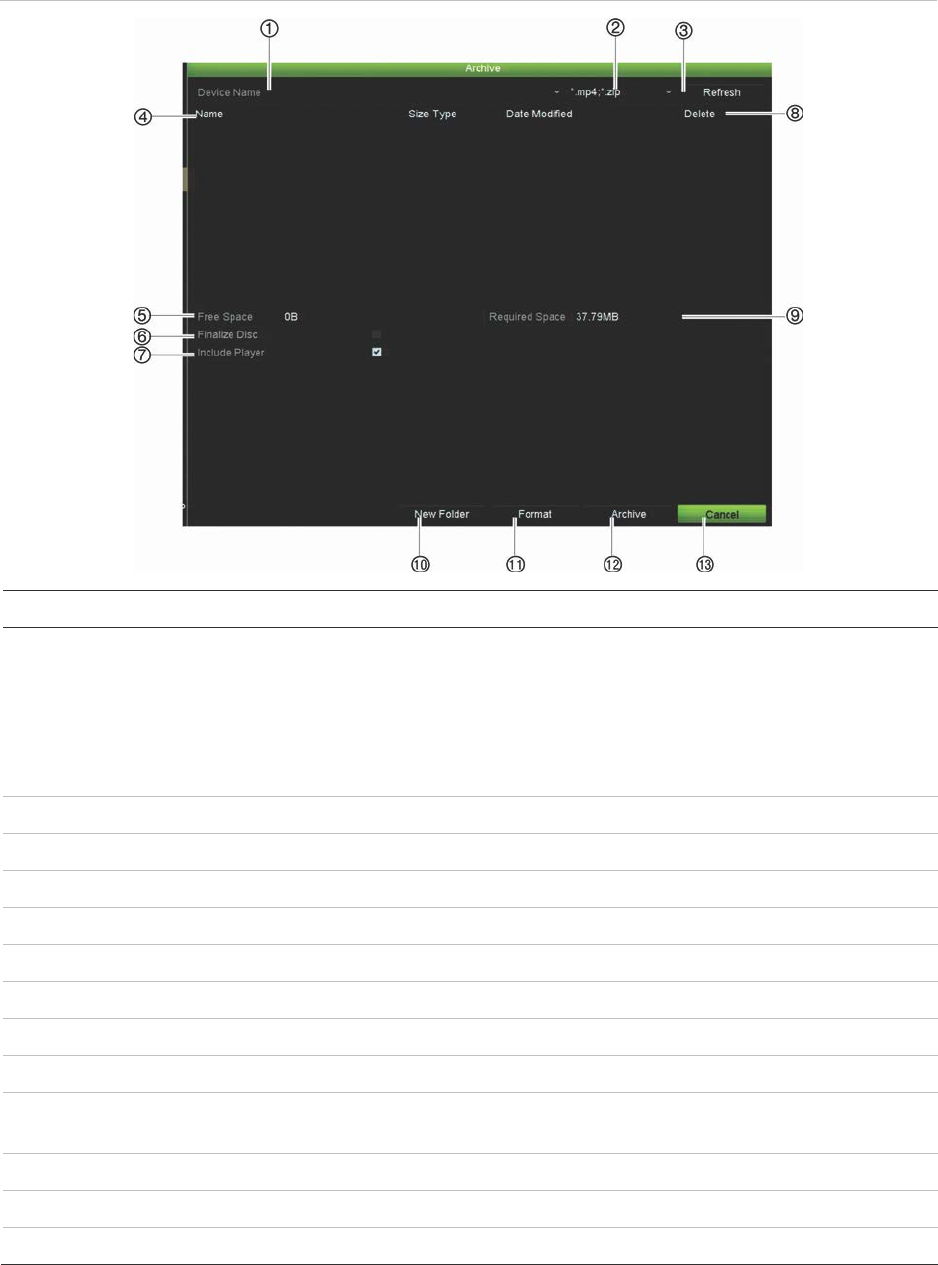
Chapter 8: Archiving files
58 TruVision NVR 11 User Manual
Figure 20: Example of an archive window
Function Description
1
. Device name Select one of the storage media for archiving. If the backup device is not
recognized:
• Click the Refresh button
• Reconnect device
• Check for compatibility from vendor
2
. Search file format Search files on the backup device with the selected format.
3
. Refresh Refresh the search results if any parameters have been modified.
4
. Name Files found on the backup device are listed.
5
. Free Space Free space available on the backup device.
6
. Finalize Disc Select to prevent other files being recorded onto the disc.
7
. Include Player Select to automatically include the Player tool when archiving files.
8
. Delete Click to delete a selected file from the backup device.
9
. Required Space Space required on the backup device for the files to archive.
10
. New Folder Create a new folder on the backup device. Files from the recorder can be
archived to a specific folder.
11
. Format Format the backup device.
12
. Archive Start downloading selected files onto the backup device.
13
. Cancel Cancel search and return to previous menu.

Chapter 8: Archiving files
TruVision NVR 11 User Manual 59
Export recorded files to a backup device
To export recorded files:
1. Connect the backup device to the recorder.
If using a USB memory drive, insert the device into the USB port on the front panel.
2. In live view mode press the Search button on the front panel or remote control.
- Or -
Right-click the mouse and select Advanced Search.
The Advanced Search window appears.
3. Select the cameras and search parameters required.
4. Click Search. The list of results appears.
5. Select the files to export.
Note: You can click the Play button to verify that the selected files are the files to
export.
6. Click Archive. The Archive window appears.
7. Select the storage medium to export to from the drop-down list.
8. Click Archive to begin the backup process of the selected files.
- Or -
Click Archive All to begin the backup process of the all the files.
Archive video clips and locked files
You can manage the video clips and locked recordings that you create during 24-hour
playback.
To archive video clips and locked files:
1. In playback mode, click the File Management button. The File Management
window appears.
2. Select the tab for the files you want to manage: Video Clips or Locked File.
3. Insert your backup device into the recorder.
4. Select the files you want to archive and click Archive or Archive All.
5. In the Archive window that appears, select from the drop-down list the backup
device to be used.
If you want to filter the existing files already on the backup device, select the file
format.
6. Click Archive. File downloading starts.
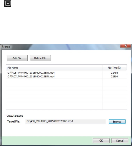
Chapter 8: Archiving files
60 TruVision NVR 11 User Manual
The files are saved onto the backup device. A pop-up screen tells you when
downloading is complete.
Merge video files in TruVision Player
You can include multiple files in the TruVision Player playlist. Double-click the desired
video file from the list and click the Start button. When the first file finishes, the next file
will automatically start.
To add exported video files to TruVision Player:
1. Click the menu icon and select Tool > Merge.
2. The Merge window appears. Click Add File to add the files you want to merge onto
a selected video file. Under Output Setting, select the video file to which you want
to add the files.
3. Click OK.
Export video recordings and snapshots via
TruVision Navigator
TruVision Navigator allows you to export a single recording file per camera. Exported
video files from TruVision Navigator need to be viewed using the TruVision export file
tool. For further information on exporting video and snapshots, please refer to the
TruVision Navigator 7.1 User Manual.
To export video and snapshots:
1. In the playback window, search for the time frame of the desired video segment.
2. Click the Video button to move the selected video segment to the Collector.
3. Select each video or snapshot thumbnail for export in the Collector, or use the
Select/Deselect All button in the Collector header bar.
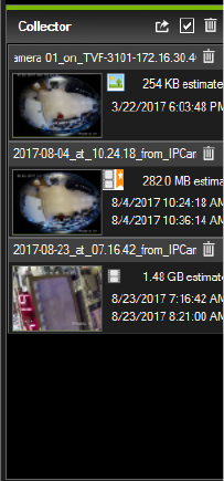
Chapter 8: Archiving files
TruVision NVR 11 User Manual 61
4. Click the Export button at the top of the Collector panel.
5. Click Browse and select the destination of the export file.
All selected video thumbnails will be exported as a single file.
6. Click the Export Now button.
Note: Make sure there is enough disk space at the destination location for the export.
Use the file size estimate in the Collector as a guideline.
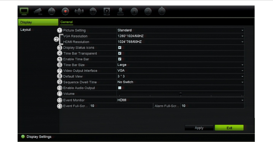
62 TruVision NVR 11 User Manual
Chapter 9
Display settings
Use the Display Settings menu to modify how the camera images appear on screen.
Display settings
Use the Display Settings menu to adjust the settings related to the local monitor output
of the recorder, such as selecting multiview layout, display the monitor time bar,
sequence dwell time options, and enable or disable the local audio output. See
Figure 21 below.
Figure 21: Display Settings window (8- and 16-channel recorders)

Chapter 9: Display settings
TruVision NVR 11 User Manual 63
Table 10: Description of the Display setup window (8- and 16-channel recorder)
Option Description
1.
Picture Setting
Define the desired output mode.
Select one of the options from the drop-down list: Standard, Bright, Soft,
or Vivid, and click Apply.
2.
VGA R
esolution 8- and 16-channel recorders only:
Define the resolution of the selected monitor. The HDMI monitor is the
main monitor by default. However, if you select HDMI to be the event
monitor, then VGA becomes the main monitor.
Select one of the options from the drop-down list. The selected
resolution must be the same as that of the monitor.
HDMI R
esolution
VGA/HDMI Resolution
4-channel recorder only:
You cannot select between VGA and HDMI monitors
so the same image
appears on both monitors.
Select one of the options from the drop-down list. The selected
resolution must be the same for both monitors.
3.
Display Status Icons
Define whether the status icons are displayed. Default is Enabled.
4.
Time Bar
Transparent Select the transparency of the monitor output time bar on screen relative
to the background to make the time bar easier to read.
Select the checkbox to enable/disable. Default is Disabled.
5.
Enable Time bar
Select whether the monitor output time bar appears on screen.
Select the checkbox to enable/disable. Default is Enabled.
6.
Time Bar Size
Select the size of the time bar: Large, Medium, or Small. Default is
Large.
7.
Video Output Interface
Select the desired video output interface as main monitor: VGA or
HDMI.
Default is VGA.
Note: You cannot select between VGA and HDMI for 4-channel
recorders. The only option displayed is VGA/HDMI.
Note: If under the Device Management > General Settings window Auto
has been selected, HDMI is by default the main monitor. You will not be
able to change the main and event monitor options here.
8.
Default View
The factory default multiview format displays all channels (2x2).
9.
Sequence Dwell Time
Set the length of time for which a camera image is displayed on the
selected monitor before moving to the next camera during sequencing.
Default is off (“No Switch”).
10.
Enable Audio Output
Select whether to hear audio from cameras in both live and playback
mode. However, in order to be able to hear audio in playback, you must
enable the audio output setting. Default is Disabled.
Select the checkbox to enable/disable audio output.
11.
Volume
Define the desired volume by using the slider.

Chapter 9: Display settings
64 TruVision NVR 11 User Manual
Option Description
12.
Event Monitor
8- and 16-channel recorders only:
Select the desired monitor, VGA or HDMI. HDMI is the default event
monitor. If the VGA monitor is selected as event monitor, then HDMI
becomes the main monitor.
Note: If under the Device Management > General Settings window Auto
has been selected, HDMI is by default the main monitor. You will not be
able to change the main and event monitor options here.
4-channel recorder only:
There is no event monitor so this option is not shown. Events pop-up in
full-screen view on both the VGA and HDMI monitors.
13.
Event Full Screen
Monitoring Dwell Time (s)
8- and 16-channel recorders:
Set the length of time during which an image is displayed on the event
monitor in full screen in case of an event. Default is 10 seconds.
4-channel recorder:
Set the length of time during which an image is displayed in full screen in
case of an event. Default is 10 seconds.
Alarm Full Screen
Monitoring Dwell Time (s)
8- and 16-channel recorders:
Set the length of time during which an image is displayed on the event
monitor in full screen in case of an alarm. Default is 10 seconds.
4-channel recorder:
Set the length of time during which an image is displayed in full screen in
case of an event. Default is 10 seconds.
Layout
The Layout window allows you to define the layout of each of the different views as they
are shown when selecting the different live views or the sequencing order.
The cameras are sequenced in numeric order by default. You can change the order of
the cameras for all monitors.
The camera order in the different views is consistent. This means that if Channel 2 is
the first camera shown in the single camera view then it will also be the top left camera
of the 4-channel view.
You can switch the tile of a camera with that of another camera in the system. This lets
you, for example, have the images of camera 1 appear on tile 10, and the images of
camera 10 appear on tile 1. This feature is useful when you want to watch the
sequence of images from specific cameras so that they are next to each other on-
screen.
See Figure 22 on page 65. Each video tile displays both the order of the camera on
screen and the camera number.
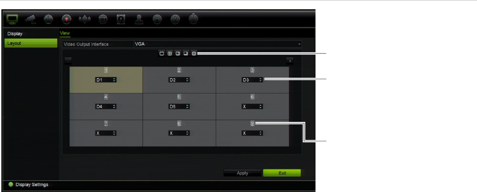
: Display settings
TruVision NVR 11 User Manual 65
Figure 22: Camera layout window
Multiview layout
selection bar
Camera order in the
sequence
Camera number
selection
66 TruVision NVR 11 User Manual
Chapter 10
Camera setup
Use the Camera Setup menu to configure IP cameras. You can also configure the
camera OSD, snapshots, recording settings, image quality, motion detection, privacy
masking, camera tampering, VCA settings, PTZ configurations, and V-stream settings.
Note: Not all settings are available for IP cameras. For advanced IP camera settings,
please consult the IP camera web browser interface.
Supported cameras
The recorder supports TruVision IP cameras up to 8 MPX as well as TVE encoders. It
also supports Gen 2 residential cameras. The recorder supports a wide range of third
party IP cameras through compliancy with the ONVIF standards for open camera
communication.
Note: UltraView cameras are not supported.
IP camera status
The IP Camera Status menu allows you to add, edit and remove IP cameras to the
recorder, as well as update the cameras’ firmware. The recorder supports all TruVision
IP cameras and encoders and is compliant with ONVIF profile S cameras.
Note: Ensure that the ONVIF camera has been tested together with the recorder before
installation.
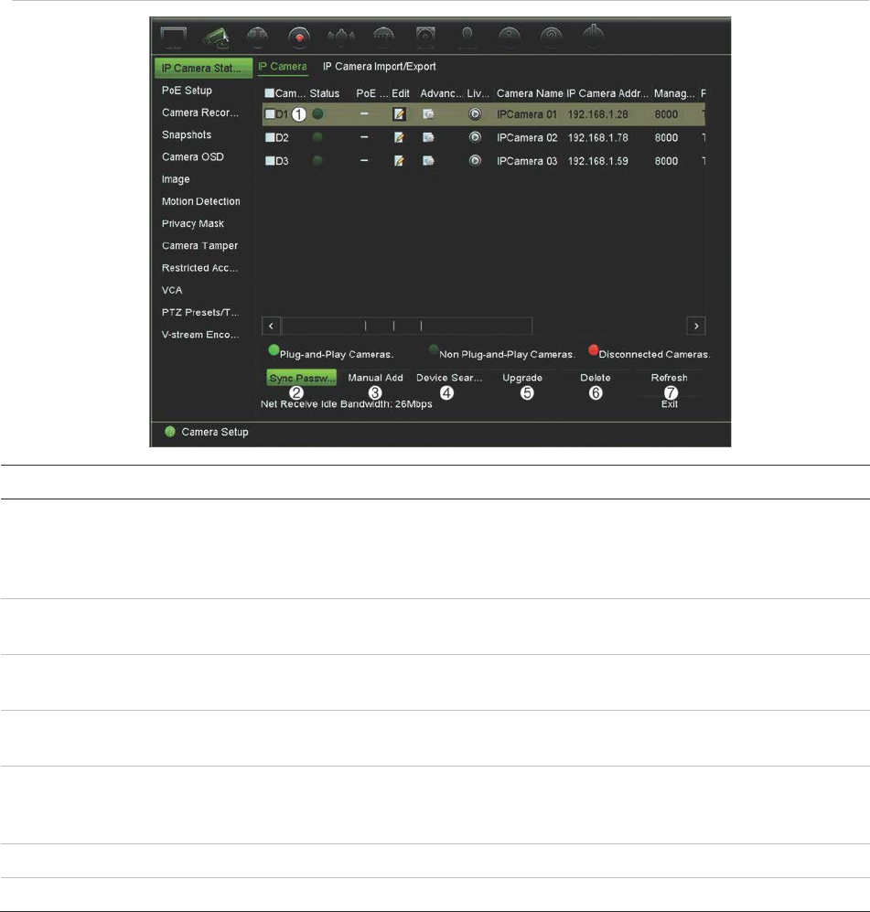
Chapter 10: Camera setup
TruVision NVR 11 User Manual 67
Figure 23: IP Camera Status window
Option Description
1.
IP camera list
This shows the list of IP cameras added to the recorder. The camera
information shown is: Camera No., Status, PoE port, Edit, Advanced Set,
Live View, Camera Name, IP Camera Address, Manage Port, Protocol,
Device Model, Serial Number, and Firmware.
2.
Sync Password
Sets all connected TruVision IP cameras to the same admin password as
the recorder.
3.
Manual Add
Add a camera manually to the recorder by entering its IP address and other
required information.
4.
Device Search/Add
Search the network for available TruVision or other natively supported IP
cameras. Add an IP camera to the recorder system.
5.
Upgrade
Upgrade IP camera software. Insert USB flash drive in the recorder and
select the upgrade file. The camera will automatically reboot once the
software is upgraded.
6.
Delete
Delete the selected IP camera from the list.
7.
Refresh
Update the information displayed on a camera in the recorder device list.
Adding IP cameras to the recorder
IP cameras and their passwords
When you add an IP camera to the recorder via the LAN or PoE ports, the system
automatically checks the camera’s password to ensure that it is the same as that of the
recorder or that it is 1234. There are two scenarios:
Chapter 10: Camera setup
68 TruVision NVR 11 User Manual
Camera already has a password (activated):
The recorder automatically detects the camera and checks its password to see if it is
the same as that of the recorder or if it is 1234. If it is either, then the camera is
successfully added to the recorder.
If the camera password is not the same as that of the recorder, nor 1234, it will be
added to the recorder but will appear as offline. You can then change the camera
password in the Camera Setup menu.
New camera without a password (not yet activated):
The recorder detects the camera and pushes its admin login and password to the
camera.
Adding IP cameras
There are two ways to connect an IP camera:
The recorder can connect to IP cameras on the LAN network
The IP cameras can be connected to the PoE ports at the back of the recorder
LAN network:
There are two ways to connect an IP camera to the LAN network:
To automatically add an IP camera via the LAN network:
1. From the menu toolbar, click Camera Setup > IP Camera Status.
2. Click Device Search/Add to search for any supported IP cameras located in the
recorder LAN. A list of the cameras found is displayed in the Add IPC window.
3. Select the checkboxes of the cameras that you want to add to the recorder.
4. Click Add to add the selected cameras to the list of devices in the recorder. Click
Back when complete in order to return to the main window.
Note: The maximum number of IP cameras that can be added is shown in the IP
Camera tab.
The cameras are added to the end of the list of devices in the IP camera window.
5. To test if a camera connection is operational, select the desired camera from the list
of devices connected to the recorder and click Live. A pop-up window will appear
showing the camera’s live view.
Note: If cameras still have default settings, they might have the same IP addresses.
This creates an IP conflict. Use the Edit button to assign a different IP address to
each camera. Ensure that for each camera to successfully connect the cameras.
6. Click Exit to return to live view.
To manually add an IP camera on the LAN network:
1. From the menu toolbar, click Camera Setup > IP Camera Status.

Chapter 10: Camera setup
TruVision NVR 11 User Manual 69
2. Click Manual Add. In the pop-up window, enter the camera details such as the IP
camera address/domain, protocol, management port, user name and password.
Click OK.
The camera is added to the end of the list of devices.
Note: Only one camera can be manually added at a time.
PoE ports:
You do not need to search for IP cameras connected to PoE ports as they are
automatically recognized when plugged in. However, they are only recognized if their
password is the same as that of the recorder or is 1234. If their password is different,
follow the instructions below to add the IP camera.
To add an IP camera with a different password to the recorder or which is not
1234:
1. Connect the IP camera to a network and set the camera’s IP address to
192.168.254.x (where “x” is between 1 and 254).
Note: The camera’s IP address must be in the same subnet as the internal NIC IPv4
address of the recorder (under Network Settings). The recorder’s default NIC IPv4
address is 192.168.254.1. However, you can use another IP address, if desired.
2. Plug the IP camera into the PoE port of the recorder.
The Plug and Play function cannot detect the camera as the passwords are
different. It cannot detect the IP address given to the camera.
3. From the menu toolbar, click Camera Setup > IP Camera Status.
4. Select the IP camera and click Edit. Change it from Plug and Play to Manual.
5. Change the IP address to the address set up in step 1 and enter the password for
the camera.
6. Save the settings. The camera will be recognized and come online.
Editing camera information
To edit IP camera information
1. From the menu toolbar, click Camera Setup > IP Camera Status.
2. In the IP Camera tab, select a camera from the list displayed.
3. Click the Edit icon of the desired camera row to get the pop-up window
displaying the camera information: Camera ID number, IP camera address/domain,
protocol, management port, stream number, transfer protocol, user name, and
password.
4. Change the information as required.
5. Click OK to save the changes and return to the IP Camera window.
6. Click Exit to return to live view.
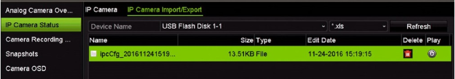
Chapter 10: Camera setup
70 TruVision NVR 11 User Manual
Importing/exporting IP camera files
You can export the configuration information on the IP cameras to an MS Excel file via
the browser or through a USB port. The information in the exported file can be modified
but the file structure must not be changed.
This file can also be imported to the recorder.
To export IP camera settings:
1. Insert the archive device in a USB port of the recorder.
2. From the menu toolbar, click Camera Setup > IP Camera Status > IP Camera
Import/Export.
3. Select the archive device and click Export. A pop-up message appears to say that
the file has been successfully exported to the archive device and the exported file is
listed on-screen.
To import IP camera settings:
1. Insert the archive device in a USB port of the recorder with the MS Excel file to be
imported.
2. From the menu toolbar, click Camera Setup > IP Camera Status > IP Camera
Import/Export.
3. Select the archive device and click Import. A pop-up message appears to say that
the file has been successfully exported to the recorder.
PoE setup
It is important when installing IP cameras to calculate the total power consumption
required so that it is less than the power budget of the recorder switches. The recorder
lets you easily track on-screen the current and remaining power consumption for all
cameras directly connected to its switches. See Figure 24 on page 71.
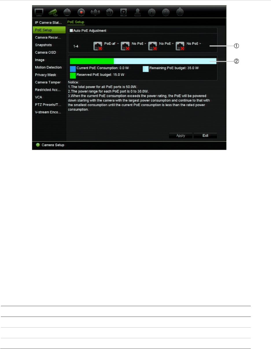
Chapter 10: Camera setup
TruVision NVR 11 User Manual 71
Figure 24: PoE power budget information on IP cameras (4-channel PoE recorder shown)
1. Select the PoE type required for each camera.
2. Dynamic tracking of the current PoE power consumption (blue), unallocated PoE power (white), and
remaining allocated PoE power budget (green) shown.
The IP cameras will specify which type of PoE they require. You can set up each
camera individually for no PoE, PoE-af, PoE-at, or 12.5 W for 4- and 16-channel
recorders and 15 W for 8-channel recorders. A PoE port can support up to 30 W
maximum.
The recorder has up to 16 PoE ports, depending on the model. The total PoE power
budget for the 4-channel recorder is 50 W, for the 8- channel recorder it is 120W and
for the 16-channel recorder it is 200 W.
The PoE-af port can support between 0 and 15.4 W and the PoE-at port can support
between 0 and 30 W. See Table 11 below for a description of the maximum number of
IP cameras that can be connected depending on the PoE type used.
Table 11: Maximum number of IP cameras that can be connected by PoE power consumption
NVR
12.5 W 15 W PoE-af PoE-at
4
-channel 4 - 3 1
8
-channel - 8 7 4
16
-channel 16 - 12 6
To display the PoE power consumption information:
1. From the menu toolbar, click Camera Setup > PoE Setup.
2. Select the PoE type required for each camera: No PoE, PoE-af, PoE-at, or 12.5 W.
3. Click Apply to save the settings. Click Exit to return to live view.
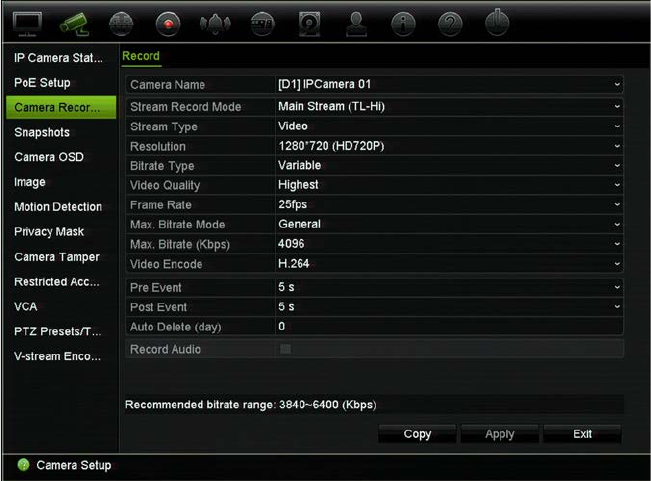
Chapter 10: Camera setup
72 TruVision NVR 11 User Manual
Camera recording settings
The camera recording settings allow you to define the configuration per camera per
stream recording mode.
To configure recording settings:
1. From the menu toolbar, click Camera Setup > Camera Recording Settings.
2. Select the camera you want to configure.
3. Configure the following recording settings (options available depend on the camera
model):
• Stream Record Mode: Select one of the stream types to configure the recording
parameters of that record mode: Mainstream (TL-Hi) (default), Mainstream (TL-
Lo), Mainstream (Event), Mainstream (Alarm), or Substream.
• Stream Type: Select the type of stream to record, either Video or Video & Audio.
Default is Video.
• Resolution: Select the resolution of the recording. Options include (depending
on the camera): 8 MPX, 6 MPX, 5 MPX, 4 MPX, QXGA (3 MPX), 1080P, UXGA
(2 MPX), SXGA, 960P (1.3 MPX), HD720P, SVGA, D1, 4CIF, VGA, DCIF, 2CIF,
CIF or QCIF.
• Bitrate Type: Select Variable (default) or Constant. If “Variable” is selected, the
bandwidth can vary depending on video quality and the bandwidth required. If
“Constant” is selected the video streaming is always at the maximum bit rate
selected.
• Video Quality: Select the quality at which to record. If “Constant” is selected as
the bit rate type, this option is unavailable.

Chapter 10: Camera setup
TruVision NVR 11 User Manual 73
If a low video quality is selected, the image quality is poorer and the bandwidth
required is reduced thereby allowing recording over a longer period of time.
• Frame Rate: Select the recording frame rate.
• Max. Bitrate Mode: Select the General (default) or Custom (32-16384) option.
• Max. Bitrate (Kbps): If the customized maximum bit rate mode was selected,
enter the value here. It must be between 32 and 10240 kbps. It is calculated from
the frame rate and time required. Default is 4096.
• Video Encode: Select the desired video encoding standard. Select H264 or
H.265.
• Pre Event: This is the time the camera starts recording before the event. Select
the time in seconds from the list to start pre-recording before the event. Default is
5 seconds.
The maximum pre-recording times available depend on the bit rate. See
“Maximum storage times” in the appendix.
• Post Event: This is the time the camera continues to record after the event.
Select the time in seconds from the list to stop post-recording after the event.
Default is 5 seconds.
• Auto Delete (day): Select the number of days after which recorded video from
the specified camera is permanently deleted from the HDD. A “day” is defined as
the 24-hour period from when the auto delete mode (ADM) was set.
The maximum number of days that can be set is 9999. However, the actual
number of days permitted depends on the HDD capacity. If the value is set to ‘0’,
the option is disabled. Default is Disabled.
Caution: When setting the data retention period for recordings, please ensure
that you comply with your national legislation.
• Record Audio: Enable to record sound with the images. Default is Disabled.
4. Click Apply to save the settings.
5. If you want to save these parameters to another camera, click Copy and select the
camera in the pop-up window that appears. Click OK and return to the main
window.
6. Click Apply to save the settings.
7. Click Exit to return to live view.
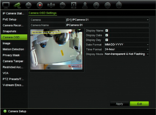
Chapter 10: Camera setup
74 TruVision NVR 11 User Manual
Snapshots
You can define the image quality and resolution of snapshots for each camera.
Snapshots can be taken at any time during live view or playback. They can also be
created when an alarm occurs and sent by email or sent to an FTP server.
To configure snapshots:
1. From the menu toolbar, click Camera Setup > Snapshots.
2. Select the desired camera.
3. Select the snapshot resolution from the drop-down list.
Select QCIF, CIF, 4CIF, or Maximum for the recording resolution. If you select
“Maximum” and the original resolution is higher than 1080P, it will be compressed to
1080P. If the original resolution is less than 1080P, it will stay its original size.
4. Select the snapshot quality from the drop-down list (low, medium or high).
5. Click Apply to save the settings.
6. Click Exit to return to live view.
Camera OSD
The recorder lets you configure which information is displayed on-screen for each
individual camera.
The on-screen display (OSD) settings appear in live view mode and include the camera
name, time and date. They are part of the image and are therefore also recorded.
To configure the OSD settings:
1. From the menu toolbar, click Camera Setup > Camera OSD.
2. Under Camera, select the desired camera.
Chapter 10: Camera setup
TruVision NVR 11 User Manual 75
3. Under Camera Name, enter a name for the camera, if required. The name can have
up to 32 alphanumeric characters.
4. Select the Display Name, Display Date, and Display Day checkboxes to display
the camera name, date, and week.
5. Select a date format and a time format.
6. Select how you want the camera information displayed.
Select one of the options from the drop-down list. Default is non-transparent/non-
flashing.
• Transparent & Flashing
• Transparent & Not flashing
• Non-transparent & Flashing
• Non-transparent & Not flashing
7. There are two colored text boxes in the camera view window; one for the camera
name (red box) and the other for the date/time (yellow box). Using the mouse, click
and drag a text box to the display position.
8. To copy the settings to other cameras, click Copy and select the desired cameras.
Click OK.
9. Click Apply to save the settings and then click Exit to return to live view.
Image settings
This function allows you to adjust image settings for each individual camera channel.
You may need to adjust the camera image depending on the location background in
order to get the best image quality.
You can also manually adjust the brightness, contrast, saturation, and hue values.
Note: These options can also be modified from the image settings button on the live
view toolbar (see “Live view toolbar” on page 31).
To adjust display settings:
1. From the menu toolbar, click Camera Setup > Image.
2. Under Camera, select the desired camera.
3. Under Image Setting, only Custom is available.
4. Adjust the brightness, contrast, saturation, sharpness and hue values by dragging
each scroll bar.
Click the Default button to return image setting values to the default position.
5. Select how you want the camera to rotate the image. There are two rotate functions:

Chapter 10: Camera setup
76 TruVision NVR 11 User Manual
Enable Rotate You can rotate the image 270°
In a vertical-shaped scene, such as a hallway or corridor, the image
is shown with a vertical (tall) rather than horizontal (wide) format. The
video image is at a 9:16 aspect ratio.
Mirror Mode You can flip the camera image three ways:
Left-Right: Flip the image horizontally.
Up-Down: Flip the image vertically.
Center: Flip both horizontally and vertically.
Note: This is only available for cameras that support the function.
6. Click Apply to save the settings and then click Exit to return to live view.
Motion detection
The motion detection menu allows you to enable or disable motion detection for each
camera, as well as create motion grids, set the sensitivity of the motion detection and
link motion detection to a specific action.
To set up motion detection:
1. From the menu toolbar, click Camera Setup > Motion Detection.
Areas covered by the red grid are sensitive to motion detection.
2. Select the camera to detect motion. Each camera must be set up individually.
3. Select Enable Motion Detection. If this is not enabled, motion will not be recorded.
4. Select Enable Dynamic Analysis. This allows you to see on-screen motion being
detected while setting up the feature. Areas where motion is detected are shown as
solid red squares in the motion grid.
5. Create the areas on-screen to be sensitive to motion.
Click and drag the mouse cursor across the window to select areas sensitive to
motion detection, which are shown as a red motion grid.
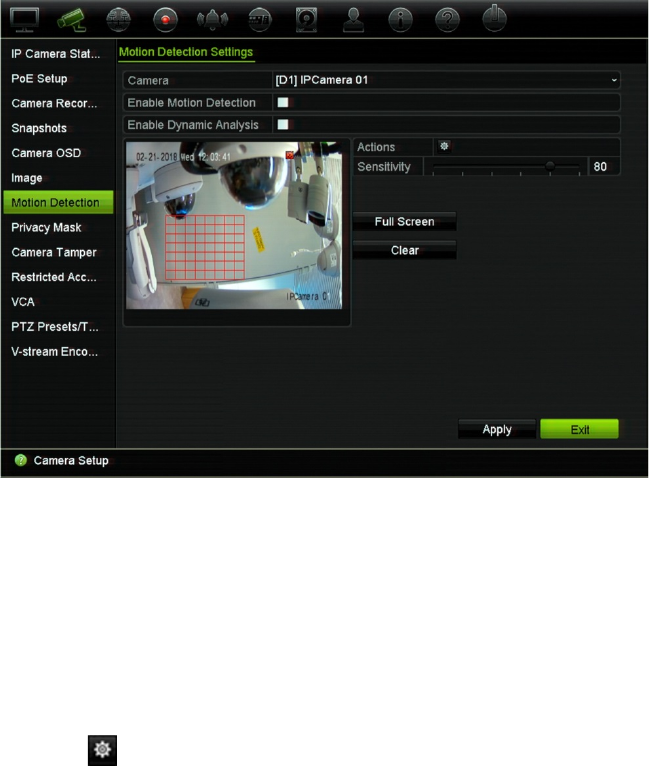
Chapter 10: Camera setup
TruVision NVR 11 User Manual 77
Click Full Screen to activate the whole screen or Clear to clear the screen.
6. Set the sensitivity level.
Drag the Sensitivity scroll bar to the desired sensitivity level. Default is 80. Maximum
sensitivity is 100.
7. Select the cameras that will start the motion recording schedule once motion is
detected.
Click the Actions button. The Actions window appears. Click the Trigger
Channel tab and select the cameras that will record when a motion alarm is
triggered. Click Apply to save the settings.
8. Select the arming schedules for motion detection.
In the Actions window, click the Arming Schedule tab and select the day of the
week and the time periods during the day when motion can be recorded. You can
schedule up to eight time periods in a day. Default is 24 hours. Note that when
motion detection is enabled, motion events will always trigger event recording,
regardless of the arming schedule.
Note: Time periods defined cannot overlap.
Click Apply to save the settings. Click Copy to copy the settings to other days of
the week.
9. Link the corresponding action to motion detection.
In the Actions window, click the Actions tab to define the method by which you want
the recorder to notify you of the alarm: Full-screen Monitoring, Enable Alarm Audio,
Notify Alarm Host, Send Email, Upload Snapshots to FTP, and Trigger Alarm
Output. See “Event notification” on page 107 for the list of alarm notification types
available. More than one option can be selected.
Click Apply to save settings.
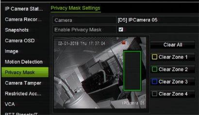
Chapter 10: Camera setup
78 TruVision NVR 11 User Manual
10. Click OK to return to the motion detection settings window.
11. Click Apply to save all settings.
12. Click Exit to return to live view.
Privacy mask
You can define an area on screen to remain hidden from view and recording. For
example, you can choose to block the view of a camera when overlooking residential
premises. This hidden area is referred to as privacy masking. Privacy masking cannot
be viewed in live view or recorded mode, and appears as a black area on the video
image.
The permitted number of privacy masks is determined by the number supported by the
camera.
To setup a privacy mask:
1. From the menu toolbar, click Camera Setup > Privacy Mask.
2. Select the camera for which to set up privacy masking.
3. Select the Enable Privacy Mask checkbox to enable the feature.
4. Set up the mask area. Up to four areas can be set (depending on the camera).
Using the mouse, click and drag a privacy-mask box in the camera view window
over the desired area. You can set up to four areas for privacy masking. Masked
areas are dimmed and outlined in four different colors. Click Apply to save settings.
To delete a mask, click Clear All. All the masks are deleted.
5. To copy the settings to other cameras, click Copy and select the desired cameras.
Click OK.
6. Click Apply to save the settings and then click Exit to return to live view.
Chapter 10: Camera setup
TruVision NVR 11 User Manual 79
Camera tamper
You can setup the recorder to alert you when the camera view has changed such as
when someone has deliberately blocked the camera view by spraying paint on the lens
or by moving the camera. Tampering detection only applies when the whole image is
covered and all light is blocked. You can select a specific area of the camera screen to
detect tampering.
Note: It is strongly recommended not to configure for video tampering when using PTZ
dome cameras.
To set up video tampering detection:
1. From the menu toolbar, click Camera Setup > Camera Tamper.
2. Select a camera to configure for video loss detection.
3. Select the Enable Camera Tamper checkbox to enable the feature.
4. Select the tamper detection sensitivity level by clicking the sensitivity scroll bar. The
maximum sensitivity value is 3.
5. Set up the tamper detection area.
Using the mouse, click and drag a privacy-mask box in the camera view window
over the desired area. You can set up one area. Click Clear to delete the area. Click
Apply to save settings.
6. Select the arming schedule for the tamper.
Click Actions and then select the Arming Schedule tab to select the day of the
week and the time periods during the day when motion can be recorded. You can
schedule up to eight time periods in a day. Default is 24 hours.
Click Apply to save the settings. Click Copy to copy the settings to other days of
the week and holiday period.
Note: The time periods defined cannot overlap.
7. Select the response method.
Click Actions and then select the Actions tab to select the method by which you
want the recorder to notify you of the alarm: Full-screen monitoring, Enable alarm
audio, Notify alarm host, Send email, and Trigger alarm output. See page 105 for
the description of alarm notification types.
Click Apply to save settings and then OK to return to the main window.
8. Click Exit to return to live view.
Restricted access camera
Restricted access cameras are cameras that are only visible to specific users.
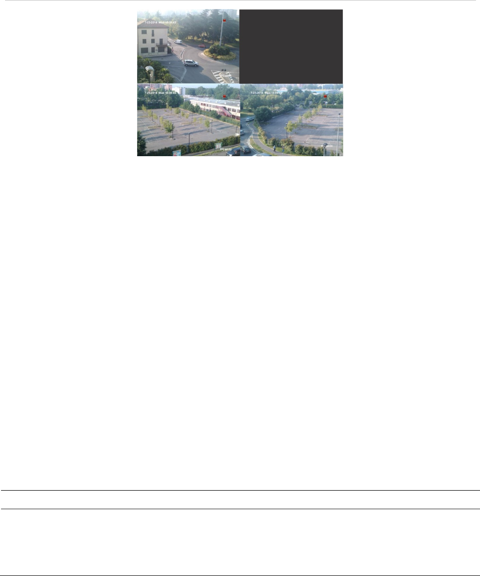
Chapter 10: Camera setup
80 TruVision NVR 11 User Manual
There may be occasions when you want to control who can see a camera image on a
local monitor, such as if there is a camera located in a changing room. The recorder
lets you select which camera (or cameras) is not displayed on the local monitor unless
the user is logged in and has permission to view the camera images. A restricted
access camera is not displayed on screen when no user is logged in. Instead a person
walking by sees a black screen. See Figure 25 below.
Figure 25: Example of a restricted access camera image
To set up a camera for a restricted access view:
1. From the menu toolbar, click Camera Setup > Restricted Access Camera.
2. Select which cameras you want to have restricted access and click Apply.
3. Click Exit to return to live view.
VCA setup
The configuration of each individual VCA (Video Content Analysis) event is done in the
camera browser. Within the recorder you can link actions to a VCA alarm from IP
cameras that support this feature.
There are several types of VCA events to select, depending on the camera model. A
series of linkage methods can be triggered if a VCA event is detected. See Table 12
below.
Note: VCA events trigger recordings; they are marked in the recorder and allow you to
easily find the assisted video.
Table 12: VCA types
VCA event types Description
Face Detection When this function is enabled, the camera can detect a moving
object that is moving towards it, triggering a configurable response.
The camera can only detect a face looking directly into the camera,
not side views. This feature is best suited when the camera is in
front of a door or is located in a narrow corridor.

Chapter 10: Camera setup
TruVision NVR 11 User Manual 81
VCA event types Description
Cross Line Detection Use this function to detect people, vehicles, and objects crossing a
pre-defined line or an area on-screen. The line crossing direction is
set as bidirectional only. Bidirectional is crossing the line from both
directions. Only one cross line is supported.
Intrusion Detection Use this function to set up an area in the surveillance scene to
detect when intrusion occurs. If someone enters the area, a set of
alarm actions can be triggered.
Object Left Behind Detection Use this function to detect objects left in the designated region
such as baggage, a purse, dangerous materials, etc.
Object Removed Detection Use this function to detect objects removed from a designated
region, such as exhibits on display.
Enter Region Detection Use this function to detect people, vehicle, or other objects that
enter a designated region from outside the designated region.
This function can only be defined via the browser.
Exit Region Detection Use this function to detect people, vehicle, or other objects that exit
from a designated region, and certain actions can be configured to
occur when the alarm is triggered.
This function can only be defined via the browser.
Defocus Detection Use this function to detect image blur caused by defocusing of the
lens, triggering a series of alarm actions.
The sensitivity level determines how much blur is tolerated by the
camera before triggering an alarm. When enabled, the camera
regularly checks the level of image focus (to allow for variations in
light during the day) and then compares the current image to that
of the reference image to see if there is a difference. A high
sensitivity level means that there cannot be a large variance
between the reference and current image.
This function can only be defined via the browser.
Sudden Scene Change Use this function to configure the camera to trigger an alarm when
the camera detects a change in the scene caused by a physical
repositioning of the camera.
This function can only be defined via the browser.
Audio Input Exception Use this function to detect sounds that are above a selected
threshold.
You can set it to detect a sudden rise and/or fall in sound intensity.
The smaller the sensitivity level set, the larger the change in sound
needs to be to trigger detection. The sound intensity threshold
filters the sound in the environment. The louder the environmental
sound, the higher the value.
This function can only be defined via the browser.
To setup VCA alarm actions via the OSD:
1. From the menu toolbar, click Camera Setup > VCA.
2. Select the camera for which to set up the VCA alarm.
3. Select the Enable VCA Alarm checkbox to enable the feature.
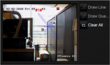
Chapter 10: Camera setup
82 TruVision NVR 11 User Manual
Note: This option is not available if Audio Exception is selected as the VCA type.
4. Select the desired VCA type.
a) Face Detection:
Select the Face Detection checkbox and then under Rule, click the rule number.
Click Rule Settings. In the pop-up window set the sensitivity level for this detection.
Only one rule can be set. Click OK.
- Or -
b) Cross Line Detection:
Select the Cross Line Detection checkbox. Click Draw Line and click on the
camera image where you want the detection line to start. Click another area on the
image as the end point of the line. By default a bidirectional line appears on screen.
Up to four lines can be set, each with a different rule. Click Clear All to clear the
line.
Set up a rule to be associated with this line. Under Rule, select a rule from the drop-
down list and click Rule Settings. In the pop-up window, select the direction:
A<->B: Only the arrow on the B side is displayed. When an object moves across
the plane in both directions, it is detected and alarms are triggered.
A->B: Only an object crossing the pre-defined line from the A to the B side can be
detected and trigger an alarm.
B->A: Only an object crossing the pre-defined line from the B to the A side can be
detected and trigger an alarm.
Set the sensitivity level between 1 and 3. Click OK to return to the menu window.
To draw a new line, if required, select another rule from the drop-down list and then
draw the line and set its rule values.
- Or -
c) Intrusion Detection:
Select the Intrusion Detection checkbox. Click Draw Quadrilateral and click on
the camera image where you want the detection area to start. When you draw the
rectangle, all lines should connect end-to-end to each other. Up to four areas are
supported, each with its own rule. Click Clear All to clear the area you have drawn.
Note: The area can only be quadrilateral.

Chapter 10: Camera setup
TruVision NVR 11 User Manual 83
Set up a rule to be associated with this detection region. Under Rule, select a rule
from the drop-down list and click Rule Settings. In the pop-up window, select the
time threshold and sensitivity levels.
The time threshold is the object remains in the region. If you set the value as 0 s,
the alarm is triggered immediately after the object enters the region. The range is
between 0 and 10.
The sensitivity value defines the size of the object that can trigger the alarm. When
the sensitivity is high, a small object can trigger an alarm. The range is between 1
and 100.
Click OK to return to the menu window.
To draw another area, select another rule from the drop-down list and then draw the
area and set its rule values.
- Or -
d) Object Left Behind Detection:
Select the Object left Behind Detection checkbox. Click Draw Quadrilateral and
click on the camera image where you want the detection area to start. When you
draw the rectangle, all lines should connect end-to-end to each other. Only one area
is supported.
Under Rule, click the rule number. Click Rule Settings. In the pop-up window set
the sensitivity level and time threshold for this detection. The time threshold can be
up to 100 seconds. Only one rule can be set.
Click Clear All to clear the area you have drawn.
- Or -
e) Object Removed Detection:
Select the Object Removed Detection checkbox. Click Draw Quadrilateral and
click on the camera image where you want the detection area to start. When you
draw the rectangle, all lines should connect end-to-end to each other. Only one area
is supported.
Under Rule, click the rule number. Click Rule Settings. In the pop-up window set
the sensitivity level and time threshold for this detection. The time threshold can be
up to 100 seconds. Only one rule can be set.
Click Clear All to clear the area you have drawn.
Click OK to return to the VCA window.
5. Select the recording schedules for the selected VCA.
Click the Actions button to define which actions are required with each selected
VCA event from each camera.
In the Actions window, click the Trigger Channel tab and then select the cameras
to be triggered for recording when an alarm is detected. Click Apply to save the
settings and then OK to return to the VCA window.
Chapter 10: Camera setup
84 TruVision NVR 11 User Manual
6. Select the arming schedules for the VCA event.
In the Actions window, click the Arming Schedule tab and select the day of the
week and the time periods during the day when motion can be recorded. You can
schedule up to eight time periods in a day. Default is 24 hours.
Note: The time periods defined cannot overlap.
Click Apply to save the settings. Click Copy to copy these settings to other days of
the week. Click OK to return to the VCA window.
7. Select the response method to a VCA event.
In the Actions window, click the Actions tab to define the method by which you want
the recorder to notify you of the alarm: Full-screen Monitoring, Enable Alarm Audio,
Notify Alarm Host, Send Email, and Trigger Alarm Output. See page 105 for the
description of alarm notification types. More than one option can be selected.
Click Apply to save the settings and then OK to return to the VCA window.
8. Select the PTZ camera function required in response to a VCA alarm.
In the Actions window, click the PTZ Linking tab. Select the PTZ camera and enter
the number of preset, preset tour or shadow tour that is triggered when the alarm is
detected.
9. Click Apply to save all the settings and then click Exit to return to live view.
PTZ presets and tours
Presets are previously defined locations of a PTZ dome camera. It allows you to quickly
move the PTZ dome camera to a desired position. They are configured and modified
from the Camera Setup > PTZ Presets/Tours window (see Figure 26 below).
Tours are series of presets. Shadow tours allow you to record the manual movement of
a PTZ and follow the same tour at a later date.
Note: The PTZ dome camera used must be able to support a preset command.
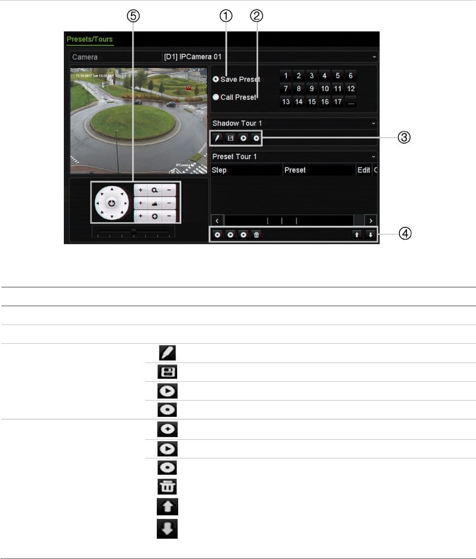
Chapter 10: Camera setup
TruVision NVR 11 User Manual 85
Figure 26: PTZ configuration window
Table 13: Description of the PTZ Presets/Tours configuration window
Name Description
1
. Save Preset Saves preset.
2
. Call Preset Calls up pre-existing preset.
3
. Shadow Tour toolbar
Starts recording the shadow tour.
Saves the shadow tour.
Starts the selected shadow tour.
Deletes the selected shadow tour.
4
. Preset Tour toolbar
Adds a step to a selected preset tour.
Starts the selected preset tour.
Stops the selected preset tour.
Deletes all the preset tour steps.
Scroll up the list.
Scroll down the list.
5
. Preset control panel
To set up a preset:
1. From the menu toolbar, click Camera Setup > PTZ Presets/Tours.
2. Use the directional, zoom, focus and iris buttons to position the analog camera in
the desired preset location.
3. Check Save Preset and enter a preset number (1 to 255). The preset is enabled
and stored in the camera.

Chapter 10: Camera setup
86 TruVision NVR 11 User Manual
If the desired preset number is larger than the 17 numbers listed, click […]. The
Preset window appears. Select a preset number from the dropdown list and click the
OK button to save changes.
Note: Presets can be overwritten.
4. Click Exit to return to live view.
To call up a preset:
1. From the menu toolbar, click Camera Setup > PTZ Presets/Tours.
2. Check Call Preset and enter the preset number to call up. The camera immediately
moves to that preset position.
3. Click Exit to return to live view.
To delete a preset:
1. From the menu toolbar, click Camera Setup > PTZ Presets/Tours.
2. From the preset list, select a preset number, and click to delete the selected the
preset.
3. Click Exit to return to live view.
To set up a preset tour:
1. From the menu toolbar, click Camera Setup > PTZ Presets/Tours.
2. Select the preset tour number.
3. In the preset tour toolbar, click to add a step to the preset tour. The Step window
appears. Select the preset number, dwell time and speed of the step. Click OK to
save the settings.
Note: A preset tour should have at least two presets.
4. Repeat step 3 to configure other steps in the preset tour.
5. In the preset tour toolbar, click to call up the preset tour.
6. Click Exit to return to live view.
To call up a preset tour:
1. Click the PTZ Settings icon on the menu toolbar and select More Settings.
2. Select the desired preset tour from the list and click to start the tour. Click
to stop the preset tour.
3. Click Back to return to live view.
To delete a preset tour:
1. From the menu toolbar, click Camera Setup > PTZ Presets/Tours.
2. From the preset tour list, select a tour number and click to delete the selected
the preset tour.
– Or –

Chapter 10: Camera setup
TruVision NVR 11 User Manual 87
In the preset tour toolbar, click to delete all the preset tours.
3. Click Exit to return to live view.
To set up a shadow tour:
1. From the menu toolbar, click Camera Setup > PTZ Presets/Tours.
2. Select the shadow tour from the drop-down list.
3. To record a new shadow tour, click and use the directional buttons on the PTZ
control panel to move the camera along the desired path.
4. Click to save the shadow tour.
Note: The shadow tour can be overwritten.
5. Click Exit to return to live view.
To call up a shadow tour:
1. From the menu toolbar, click Camera Setup > PTZ Presets/Tours.
2. Select the shadow tour from the list and click to start the tour. Click to stop
the shadow tour.
3. Click Exit to return to live view.
V-stream encoding
If the available bandwidth is limited, you can remotely view several channels in real
time with one stream over the web browser or VMS (Video Management System), such
as TruVision Navigator, using the V-stream encoding option ("V" stands for "virtual").
When enabled, you can see the V-stream from the cameras on a remote client monitor
in one stream.
To enable V-streaming:
1. From the menu toolbar, click Camera Setup > V-Stream Encoding.
2. Select the Enable V-Stream Encoding checkbox to enable the feature.
3. Select the Frame Rate from the drop-down menu.
4. Select the Max. Bitrate from the drop-down menu.
Note: The layout of the V-stream can be set up via the OSD menu (Display Settings >
Layout menu) or via the webpage.
Note: If you are using a four-channel recorder and you change the V-stream format, the
HDMI/VGA monitor output will also be changed.
88 TruVision NVR 11 User Manual
Chapter 11
Network settings
The Network settings menu allows you to manage all network related aspects of the
recorder including general network settings, DDNS, NTP synchronization, email setup,
UPnP settings, FTP server setup, and IP address filter.
Additionally, the Net Detect and Network statistics menus provide you with a useful and
efficient tool to analyze the behavior of the recorder on the network.
You must correctly configure your recorder’s network settings before using it over the
network in order to:
Connect IP cameras to it
Connect to the recorder over the LAN
Connect to the recorder over the internet
Network settings
Note: As every network configuration may differ, please contact your Network
Administrator or ISP to see if your recorder requires specific IP addresses or port
numbers.
To configure general network settings:
1. From the menu toolbar, click Network Settings > Network Settings.
2. Enter the required settings:
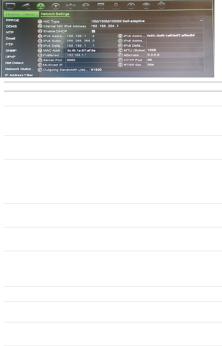
Chapter 11: Network settings
TruVision NVR 11 User Manual 89
Option Description
1.
NIC Type
Network interface card (NIC) is used to connect the recorder to a network.
Select the NIC type used from the drop-down list.
2.
Internal NIC IPv4
Address
Enter the internal NIC IPv4 address. This is the IP address of the
recorder's internal network managing only the PoE port cameras. This is
not the LAN IP address.
Default value is 192.168.254.1.
Bridge PoE
Camera Network
Check this box to enable the Bridge PoE Camera Network. This function
can only be defined via the browser.
Default value is Enable.
3.
Enable DHCP
DHCP (Dynamic Host Configuration Protocol) is a protocol for assigning
an IP address dynamically to a device each time it connects to a network.
Select this checkbox if you have a DHCP server running and want your
recorder to automatically obtain an IP address and other network settings
from that server. The DHCP server is typically available in your router.
Default value is Disabled.
4.
IPv4 Address
Enter the IP address for the recorder. This is the LAN IP address of the
recorder.
Default value is 192.168.1.82.
5.
IPv4 Subnet Mask
Enter the subnet mask for your network so the recorder will be
recognized
within the network.
Default value is 255.255.255.0.
6.
IPv4 Default
Gateway
Enter the IP address of your network gateway so the recorder will be
recognized within the network. This is typically the IP address of your
router. Consult your router user manual or contact your ISP to get the
required information on your gateway.
Default value is 192.168.1.1.
7.
MAC Address
Displays the MAC address. The MAC address is a unique identifier of your
recorder and it cannot be changed.
8.
Preferred
DNS
Server
Enter the preferred domain name server to use with the recorder. It must
match the DNS server information of your router. Check your router’s
browser interface or contact your ISP for the information.
9.
Server Port
Use the server port for remote client software access. The port range is
between 1024 and 65535.
Enter the server port value. The default value is 8000.

Chapter 11: Network settings
90 TruVision NVR 11 User Manual
Option Description
10.
Multicast IP
Enter a D-class IP address between 224.0.0.0 to 239.255.255.255. Only
specify this option if you are using the multicast function. Some routers
prohibit the use of multicast function in case of a network storm.
11.
IPv6 Address 1
Enter the IPv6 address for the recorder. This is the IP address of the local
network to which the recorder is connected.
Default value is fe80:240:3dff:fe7e:926f/64
12.
IPv6 Address 2
When the recorder is connected to an external network (such as the
internet), the second IPv6 address is automatically assigned.
13.
IPv6 Default
Gateway
Enter the IPv6 address of your network gateway so the recorder will be
recognized within the network. This is typically the IP address of your
router.
14.
MTU (bytes)
Enter a value between 500 and 9676. Default is 1500.
15.
Alternate DNS
Server
Enter the alternate domain name server to use with the recorder. It must
match the DNS server information of your router. Check your router’s
browser interface or contact your ISP for the information.
16.
HTTP Port
Use the HTTP port for remote internet browser access.
Enter the HTTP port value, which can be any port number that is not
occupied. The default value is 80.
17.
RTSP Service
Port
The RTSP (Real Time Streaming Protocol) is a network control protocol
designed for use in entertainment and communications systems to control
streaming media servers.
Enter the RTSP port value, which can be between1 to 65535. The default
value is 554.
18.
Outgoing
Bandwidth Limit
(Kbps)
The total outgoing bandwidth limit is a threshold you can set to limit the
amount of outgoing bandwidth that is being handled by the recorder.
3. Click Apply to save the settings and Exit to return to live view.
PPPoE settings
Although not usually used, you can connect the recorder directly to a DSL modem. To
do this, you need to select the PPPoE option in the network settings. Contact your ISP
to get the user name and password.
To configure PPPoE settings:
1. From the menu toolbar, click Network Settings > PPPoE.
2. Select the enable PPPoE checkbox.
3. Enter your user name and password, and confirm the password.
4. Click Apply and manually reboot the recorder to save the settings.

Chapter 11: Network settings
TruVision NVR 11 User Manual 91
DDNS settings
DDNS servers allow you to connect to your recorder using a dynamic address. This
dynamic address needs to be registered with a DNS service. The DDNS setup menu
allows you to enable or disable DDNS and to configure it using ezDDNS, No-IP or
DynDNS.
Note: Some service providers block the default RTSP streaming port 554 used for
video streaming, so if you are not receiving video images over the internet, you may
need to change it to another value. See Appendix C “Port forwarding information” on
page 137 for more information. See “Port forwarding information” in the appendix for
more information.
There are three ways to set up a DDNS account:
• ezDDNS: A free-of-charge service included with your recorder and fully managed
within the recorder interface. It is exclusive to TruVision products.
• DynDNS: A third-party service where users need to apply for a DynDNS account on
the Dyn.com website.
• No-IP: A third-party service where users need to apply for a no-IP account on the
no-ip.com website.
Caution: If you use the services of DynDNS or No-IP, your account user name and
password for these services will be sent to them in clear text format when you set up
your connection in the recorder.
Note: You cannot have two recorders with the same host name.
To set up DDNS:
1. From the menu toolbar, click Network Settings > DDNS.
2. Select the Enable DDNS checkbox to enable this feature.
3. Select one of the DDNS types listed:
ezDDNS: Click the Get URL button. The URL address to access the unit is
displayed. If no host name is specified, the DDNS will allocate one automatically.
The maximum length for the host name field is 64 characters. This limit does not
include tvn-ddns.net. An example of a host name could be max64chars.tvr-ddns.net.
- Or -
DynDNS: Select DynDNS and enter the server address for DynDNS. In the
recorder domain name field, enter the domain name obtained from the DynDNS
web site. Then enter your user name and password registered in the DynDNS
network.
For example:
Server address: members.dyndns.org
Domain: mycompanydvr.dyndns.org
Chapter 11: Network settings
92 TruVision NVR 11 User Manual
User name: myname
Password: mypassword
- Or -
NO-IP: Enter server address (for example, dynupdate.no-ip.com). In the host name
field, enter the host obtained from the NO-IP web site. Then enter the user name
and password that are registered with the No-IP network.
4. Ask your ISP service provider for your DNS server address or look it up in the
browser interface settings of your router.
Go to Network Settings and enter the preferred and alternate DNS server
addresses as well as the default gateway address.
5. Click Apply to save the settings and click Exit to return to live view.
NTP server settings
A Network Time Protocol (NTP) server can also be configured on your recorder to keep
the date and time current and accurate.
Note: If the device is connected to a public network, you should use a NTP server that
has a time synchronization function, such as the server at the National Time Center (IP
Address: 210.72.145.44) or europe.ntp.pool.org. If the device is setup in a more
customized network, NTP software can be used to establish a NTP server used for time
synchronization.
To set up an NTP server:
1. From the menu toolbar, click Network Settings > NTP.
2. Select the NTP checkbox to enable feature. It is disabled by default.
3. Enter the NTP settings:
• Interval (min): Time in minutes to synchronize with the NTP server. The value
can be between 1 and 10080 minutes. Default is 60 minutes.
• NTP Server: IP address of the NTP server. Default is time.nist.gov.
• NTP Port: Port of the NTP server. Default is 123.
4. Click Apply to save the settings and click Exit to return to live view.
Email settings
The recorder can send email notifications of alarms or notifications through the network.
Note: Ensure that the DNS address has been set up correctly beforehand.

Chapter 11: Network settings
TruVision NVR 11 User Manual 93
To configure email settings:
1. From the menu toolbar, click Network Settings > Email.
2. Enter the required settings.
Option
Description
En
able Server
Authentication
Select the checkbox if your mail server requires authentication and
enter the login user name and password.
User Name
If the mail server requires authentication, enter the login user name.
Password
If the mail server requires authentication, enter the login password.
SMTP Server
Enter the SMTP server’s IP address.
SMTP Port
Enter the SMTP port. The default TCP/IP port for SMTP is 25.
Enable SSL/TLS
Select the checkbox to enable TLS and encrypt emails. If the
destination server does not support TLS, the recorder will default to
SSL.
If disabled, emails will not be encrypted and will be sent in clear text.
Sender
Enter the name of the sender of the email.
Sender’s Address
Enter the sender’s email address.
Select Receiver
Select an email recipient. Up to three receivers can be selected.
Receiver
Enter the name of the receiver of the email.
Receiver’s Address
Enter the email address of the receiver.
Include Snapshot
Select the Attach JPEG File checkbox if you want to send an email
with attached alarm images.
Interval
Select an interval range in the Interval box. The default interval is 2
seconds.
The interval range represents the time range in between the
alarm/event snapshots being sent. For example, if you set the interval
range at two seconds, the second alarm/event snapshot will be sent
two seconds after the first alarm image.
3. Click Test to the test email settings.
Note: We recommend that you test the email settings after entering values in the
email window.
4. Click Apply to save the settings and click Exit to return to live view.
Configure an FTP server to store snapshots
The recorder can upload snapshots of an event or alarm to an FTP server for storage.
When the alarm or event action option “Upload Snapshots to FTP” is enabled, the
system sends snapshots every two seconds to the ftp site from each of the triggered
cameras for as long as the alarm/event is active.
Note: It is not possible to stream video to an FTP site.
Chapter 11: Network settings
94 TruVision NVR 11 User Manual
To configure the FTP server settings:
1. From the menu toolbar, click Network Settings > FTP.
2. Select the Enable FTP checkbox.
3. Enter the FTP server information.
4. Select the directory to use (root, parent, or secondary). If Parent or Secondary were
selected, select the desired options for them.
5. Click Apply to save the settings and click Exit to return to live view.
SNMP settings
SNMP is a protocol for managing devices on networks. When you enable SNMP in the
menu, network management systems can retrieve recorder status information from the
recorder via SNMP.
When you set the trap address and trap port in the recorder menu to the network
management system’s IP address and port number, and set up the network
management system as trap receiver, trap notifications (such as startup) are sent from
the recorder to the network management system.
Before configuring this function, you must first install the SNMP software.
To configure SNMP protocol settings:
1. From the menu toolbar, click Network Settings > SNMP.
2. Select the Enable SNMP checkbox.
3. Enter the required settings.
4. Click Apply to save the settings and click Exit to return to live view.
UPnP settings
The recorder supports UPnP (Universal Plug and Play). This feature lets the recorder
automatically configure its own port forwarding, if this feature is also enabled in the
router.
You can select one of two methods to set up UPnP:
Automatic mapped type: The recorder automatically uses the free ports available that
were set up in the Network Settings menu.
Manual mapped type: You enter the particular external port settings and IP addresses
required to connect to the desired router (see Figure 27 on page 95).
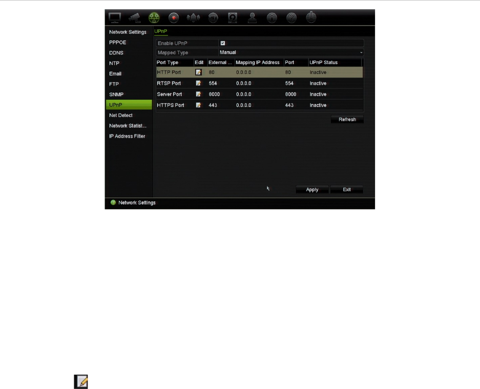
Chapter 11: Network settings
TruVision NVR 11 User Manual 95
Figure 27: UPnP manual configuration screen
To enable UPnP:
1. Connect the recorder to the router.
Note: The router must support UPnP and this option must be enabled.
2. From the menu toolbar, click Network Settings > UPnP.
3. Select the Enable UPnP checkbox.
4. From Mapped Type, select Auto or Manual.
If Manual is selected, enter the external ports and IP addresses required. Click the
Edit icon to change the values.
5. Click Apply to save the settings and click Exit to return to live view.
Network status
You can easily check network traffic in order to obtain information about the recorder
such as its linking status, MAC address, MTU, sending/receiving rate, and NIC type.
The Network Detection window shows the network traffic between the recorder and
your local network. However, the traffic between the plug and play cameras and the
recorder is not shown.
You can also check the network connection status by testing its delay and packet loss.
To check network traffic:
1. From the menu toolbar, click Network Settings > Net Detect. The Traffic window
appears. The information displayed is refreshed once a second.
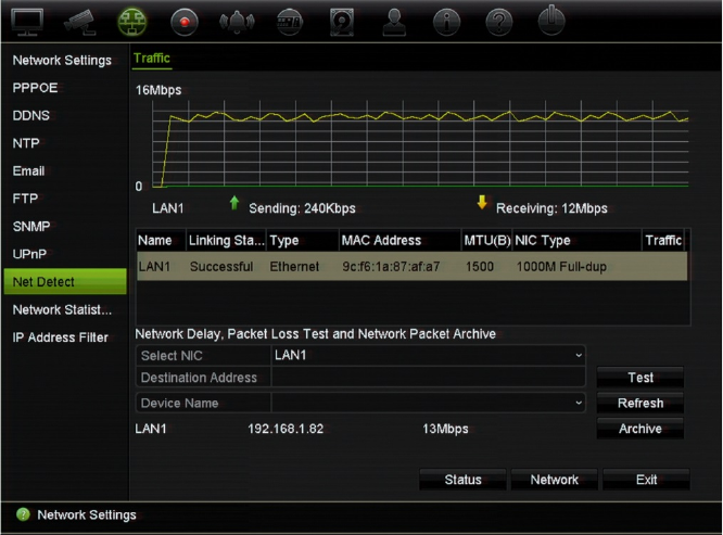
Chapter 11: Network settings
96 TruVision NVR 11 User Manual
To check network delay and packet loss:
1. From the menu toolbar, click Network Settings > Net Detect.
2. Under Select NIC, select the destination address from the drop-down list. Click
Test.
The test result appears in a pop-up window.
3. If you need to check the current network parameters, click the Network button to
get an overview. The current values for NIC type, DHCP, IPv4 address, IPv4 subnet
mask, IPv4 default gateway are shown as well as the preferred DNS server and
alternate DNS server if used.
The NIC Type and Enable DHCP options can be changed. Click Apply to save any
changes made and then click OK to return to the main window.
4. Click Exit to return to live view.
To check network status:
1. When all the network parameters have been set, click the Status button to confirm
that all parameters are operating correctly.
Archive network packet data
When the recorder is connected to a network, you can export the captured data packet
to a USB-flash drive and other local backup devices.
: Network settings
TruVision NVR 11 User Manual 97
To export network packet data:
1. From the menu toolbar, click Network Settings > Net Detect.
2. Click Refresh to get a list of the local backup devices available, which are listed
under Device Name. Select one from the list.
3. Click Archive to export the data to the backup device. Up to 1M of data can be
exported at a time.
4. Click Exit to return to live view.
Network statistics
You can easily check the bandwidth that is being used by remote live view and
playback.
To check network statistics:
1. From the menu toolbar, click Network Settings > Net Statistics.
2. The latest information is displayed on the bandwidth used by remote live view and
playback as well by Net Receive Idle and Net Send Idle. Click Refresh to update
the information.
3. Click Exit to return to live view.
Filter IP addresses
You can define the list of forbidden or allowed IP addresses that can be accessed by
the recorder. This lets you select who can access the system, increasing the system’s
security. The function is disabled by default.
To define forbidden or allowed IP addresses:
1. From the menu toolbar, click Network Settings > IP Address Filter.
2. Select the Enable IP Filter checkbox.
3. Under IP Filter Type, select Forbidden or Allowed.
4. Click Add. In the “Add IP Address” pop-up dialog box, enter the IP address to be
controlled and click OK.
Click Delete to remove IP addresses from the list.
5. If required, you can modify a saved IP address. Click Edit and enter the changes.
6. Click Apply to save the settings and click Exit to return to live view.
: Network settings
98 TruVision NVR 11 User Manual
Port forwarding
When using an internet connection, ensure that the ports are open or forwarded as
follows:
When using TruNav: Port 8000 and 554
When using a web browser: Port 80 and 554
See “Internet Explorer users” on page 141 for more information.
TruVision NVR 11 User Manual 99
Chapter 12
Recording
Use the Recording menu to define the camera recording schedules, modify the instant
playback duration, and to select the cameras for manual recording.
Recording schedule
Defining a recording schedule lets you specify when the recorder records video and
which pre-defined settings are used. Each camera can be configured to have its own
recording schedule.
The schedules are visually presented on a map for easy reference. See Figure 28 on
page 100 for a description of the recording schedule window.
Note: If a camera is set up for continuous recording, it will still switch to event recording
or alarm recording if events are triggered or to alarm recording when alarms are
triggered. This can be turned off in the individual action settings for each individual
alarm if needed.
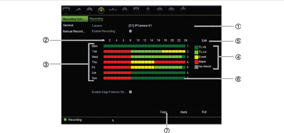
Chapter 12: Recording
100 TruVision NVR 11 User Manual
Figure 28: Description of the recording schedule window
1. Camera. Select a camera.
2. Schedule time. Represents the 24-hour cycle during which a schedule is selected.
3. Schedule map. There are eight days to select: Sunday (Sun), Monday (Mon), Tuesday (Tue),
Wednesday (Wed), Thursday, (Thu), Friday (Fri), Saturday (Sat), and Holiday (if enabled).
4. Recording type. There are five types of recording to select, which are color-coded:
Each square in the timeline represents an hour in the 24-hour period.
TL-Hi (Dark green): Continuous recording. High quality time lapse. Records high quality video.
TL-Lo (Bright green): Continuous recording. Low quality time lapse. Records low quality video. This
could be used, for example, for night recordings when few events or alarms are expected. Saving
the video in low quality helps save resources on the HDD.
Event (Yellow): Records only events, such as motion detection.
Alarm (Red): Records only alarms.
None (Grey): No recording during this period.
5. Edit button. Click to modify schedules and to copy schedules to other days of the week.
6. Timeline. There is a 24-hour time line for each day. Up to eight recording periods can be scheduled
during the 24-hour period.
7. Copy button. Click to copy schedules between cameras.
The difference between recording and alarm/VCA/event arming schedules
The recording schedule defines when a recording can occur. The alarm and event
arming schedules define when triggered alarms and motion detection can be detected.
If you want to specify when triggered alarms, VCA or motion detection can or cannot be
recorded, you also need to plan their arming schedules. See “Motion detection” on
page 76, “VCA setup” on page 80 and “Set up alarm inputs” on page 104.
For example, for motion detection if you have deactivated the detection of motion in the
arming schedule for a certain time period then, if motion happens during that period, it
will not be recorded even if you have selected event recording type in the recording
schedule.
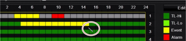
Chapter 12: Recording
TruVision NVR 11 User Manual 101
Motion detection will also not be recorded if it is not enabled (see “Motion detection” on
page 76).
Define a schedule from the recording schedule window
To set up a daily recording schedule:
1. From the menu toolbar, click Recording > Recording Schedule.
2. Select a camera.
3. Select the Enable Recording checkbox to indicate that video from this camera is to
be recorded.
4. Click a recording type in the legend to activate that record type. The cursor changes
to a pen, and a yellow box appears around the schedule map and selected
recording type.
5. Drag the pen cursor across desired hours and days in the schedule overview to
mark those times with that specific record mode. To mark areas with a different
record type, click on a different record type to activate it.
Note: You can schedule up to eight time periods in a day.
6. Click Apply to save the settings and Exit to return live view.
Define a schedule from the Edit menu
To set up a daily recording schedule:
1. From the menu toolbar, click Recording > Recording Schedule.
2. Select a camera.
3. Select the Enable Recording checkbox.
4. Click Edit. The following window is displayed:
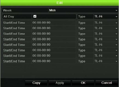
Chapter 12: Recording
102 TruVision NVR 11 User Manual
5. Select the day of the week for which you want to set up the schedule.
You can define a different schedule for each day of the week.
6. Set the start and end time for recording.
Define a time period by entering a start (left column) and end (right column) time.
You can schedule up to eight time periods. Click All Day to record all day.
Note: Time periods defined cannot overlap.
7. Select a recording type.
The recording type can be based on time and triggered by motion detection and/or
an alarm. If set to TimeLapse (TL-Hi or TL-Lo), the recorder records continuously.
8. Click Apply to save settings.
9. Repeat steps 4 to 8 for other days of the week or to copy the schedule settings to
another day.
To copy the current schedule settings to another day of the week, click Copy. Select
the number of the day of the week to which to copy the schedule. Click OK to save
changes and return to the Edit window.
10. Repeat steps 4 to 9 for the other cameras.
11. Click Apply to save the settings and OK to return to the schedule window.
The recording schedule window appears showing the schedule selected (see
Figure 28 on page 100 for an example).
Modify the instant playback duration
The live view toolbar in live view lets you quickly play back recorded video for a
preprogrammed period. You can easily change this preprogrammed time period. See
page 31 for more information on the live view toolbar.
Chapter 12: Recording
TruVision NVR 11 User Manual 103
To modify the preprogrammed time of this instant playback go to Recording >
General. Select one of the times from the drop-down list (5, 10, 20, or 30 minutes) and
click Apply. Default is 5 minutes.
Manual recording
The recorder lets you manually record video during live view. This can be useful if you
know that the recorder is not currently recording and you see something of interest on a
camera screen that should be recorded.
Once a manual recording is started, the recording continues until it is manually stopped.
If an alarm occurs during a manual recording, the alarm recording has priority over the
manual recording. If a scheduled recording is already in progress when a manual
recording is started, it continues to record as scheduled.
You can check to see if a camera is recording manually by looking at the icon on the
live view toolbar. The icon is red when manually recording. Default is off.
There are two ways to start and stop a manual recording:
•
Use the live view toolbar
You can start/stop manual recording for each camera individually. Position the
cursor over a camera image and left- click the mouse to display the live view
toolbar. Click the manual record icon to start or stop manual recording. The icon is
red when recording.
•
Use the configuration menu
This option lets you select more than one camera at a time. Go to Recording >
Manual Recording to access the manual recording menu and select the
checkboxes of the cameras to start or stop manual recording.
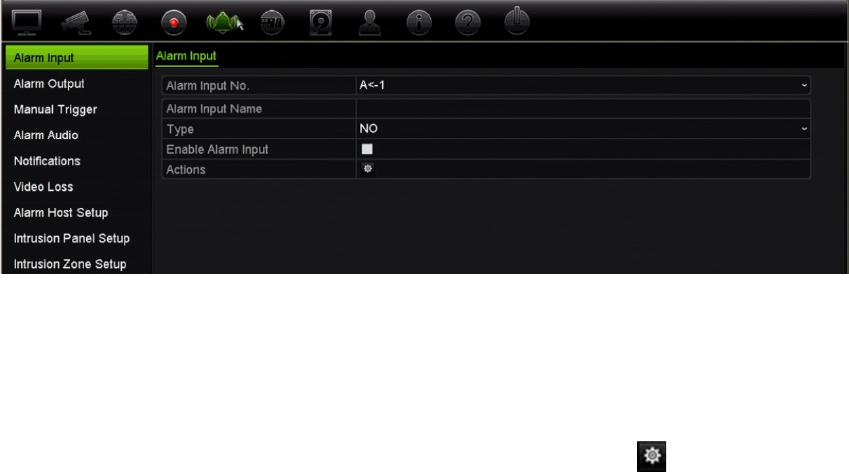
104 TruVision NVR 11 User Manual
Chapter 13
Alarm and event setup
This chapter describes the alarm and event setup menu and provides more information
on the different types of alarms and connected responses. Alarms are all notifications
related to either physical alarm inputs on recorders and cameras or anything that does
not work as expected: device errors, network issues, and video loss.
Set up alarm inputs
The recorder can be configured to record when an alarm is triggered by an external
alarm device (for example, PIR detector, dry contacts…). They are the physical inputs
on the cameras and recorder.
To set up external alarms:
1. From the menu toolbar, click Alarm & Event Setup > Alarm Input.
2. Select the alarm input number of a camera, which corresponds to the connector on
the back panel of the recorder, and enter the name of the input, if required.
3. Select the alarm input type, NO (normally open) or NC (normally closed). Default is
NO.
4. Select the Enable Alarm Input checkbox and click Actions to set up the rules
for the cameras to be triggered, their alarm schedules, method of alarm notification
and PTZ linking function.
5. Select the cameras to be triggered when an external alarm is detected.
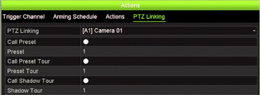
Chapter 13: Alarm and event setup
TruVision NVR 11 User Manual 105
In the Actions window, click the Trigger Channel tab and then select the cameras
to be triggered for recording when an alarm is detected. Click Apply to save the
settings.
6. Select the arming schedules for the external alarm.
In the Actions window, click the Arming Schedule tab and select the day of the
week and the time periods during the day when alarms can be recorded. You can
schedule up to eight time periods in a day. Default is 24 hours.
Click Apply to save the settings. Click Copy to copy these settings to other days of
the week.
Note: The time periods defined cannot overlap.
7. Select the response method to an external alarm.
In the Actions window, click the Actions tab to define the method by which you want
the recorder to notify you of the alarm. Select one or more of the five notification
types. See “Alarm response actions” below for a description of these alarm
notification methods.
Click Apply to save the settings.
8. Select the PTZ camera function required in response to an external alarm.
In the Actions window, click the PTZ Linking tab. Select the PTZ camera and enter
the preset, preset tour or shadow tour that is triggered when the alarm is detected.
Click Apply to save the settings.
9. Click OK to return to the alarm input window.
10. Click Apply to save all settings.
11. Click Exit to return to live view.
Alarm response actions
When setting up the rules for alarm detection, you can specify how you want the
recorder to notify you about an alarm or event. You can select more than one
notification type.
Not all alarm response actions are available for all types of alarms.
The alarm response actions are:
Chapter 13: Alarm and event setup
106 TruVision NVR 11 User Manual
• Full-screen monitoring: When an alarm is triggered, the monitor (VGA or HDMI)
displays an image in live view mode. For alarms that are triggered simultaneously,
images display one at a time every 10 seconds (default dwell time). You can set a
different dwell time using the “Dwell Time” setting under the Display
Settings>Layout window. When the alarm stops, cycling of the images stops and
you return to live view mode. This alarm option must be selected for each channel
where it is required.
• Enable Alarm Audio: Triggers an audible beep when an alarm or event is detected
by the system or a camera.
• Notify Alarm Host: Sends a signal to TruVision Navigator or other software
applications when an alarm or event is detected.
• Send Email: Sends an email when an alarm or event is detected. See “Email
settings” on page 92 for information on how to configure the recorder to send an
email.
• Upload Snapshots to FTP: Capture the image when an alarm is triggered and
upload the picture to NAS or FTP server.
• Trigger Alarm Output: Triggers an alarm output or multiple alarm outputs when a
notification is detected for an external alarm. See “Set up alarm outputs” below for
information on configuring an alarm output.
Set up alarm outputs
You can connect the recorder to an alarm system, such as a siren or intrusion system,
which is then activated when an alarm is triggered. You can select how long the alarm
signal remains active as well as schedule when alarm outputs can be triggered.
To set up an alarm output:
1. From the menu toolbar, click Alarm & Event Setup > Alarm Output.
2. Select the alarm output.
3. Select a timeout option between 5 and 600 seconds or select “Manually Clear”.
The timeout setting lets you define how long an alarm signal remains active after the
alarm has ended. If you select Manually Clear, the alarm signal remains active until
it is manually acknowledged by pressing the alarm button on the front panel or
remote control (see “Manual trigger” on page 107).
4. Select the arming schedules for the alarm output.
Click the Actions button and select the day of the week and the time periods during
the day when motion can be recorded. You can schedule up to eight time periods in
a day. Default is 24 hours.
Click Apply to save the settings. Click Copy to copy the settings to other days of
the week and holiday period.
Chapter 13: Alarm and event setup
TruVision NVR 11 User Manual 107
Note: The time periods defined cannot overlap.
5. Click OK to return to the alarm output window.
6. Click Copy to copy these settings to other cameras, if required, and then click
Apply to save the changes.
7. Click Exit to return to live view.
Manual trigger
The manual trigger menu allows you to manually trigger outputs of the recorder.
To trigger or clear alarm outputs manually:
1. From the menu toolbar, click Alarm & Event Setup > Manual Trigger.
2. Select the desired alarm output and click the following buttons:
Trigger: Trigger an alarm output or stop an alarm output. As there is only one alarm
output available, the “Trigger All” button just triggers the one output. However, if an
IP camera is connected to the recorder, then the outputs of the camera will also be
listed.
Clear All: Stop all alarm outputs at once.
3. Click Exit to return to live view. The alarm is silenced.
- Or -
Press the Alarm button on the front panel or remote control. The alarm is silenced.
Buzzer settings
When an alarm is triggered by the system or a camera, the recorder can be set up to
respond with a warning buzzer. You can modify the time during which the warning
buzzer sounds for both system and camera alarm. For example, when a physical alarm
input is continuously triggered, the buzzer will time out after the time specified.
Select Alarm & Event Setup > Buzzer Settings and select a buzzer time limit for the
system and camera alarms. Select Mute, 5 s, 10 s, 20 s, 30 s, 60 s, 120 s, 240 s, or
Constant. Default is Constant.
Event notification
You can select the alarm and event notifications to be included in the event hint icon of
the alarm center displayed in live view. Clicking the icon opens the window of the alarm
center that lists the detected alarm and event notifications. See “Status information” on
page 28 for information on the status icon displayed in the OSD.
Chapter 13: Alarm and event setup
108 TruVision NVR 11 User Manual
You can quickly check the system status by looking at the status LEDs on the front
panel.
The different types of event notifications are:
• HDD Full: All installed HDDs are full and will not record any more video.
• HDD Error: Errors occurred while files were being written to the HDD, there is no
HDD installed, or the HDD had failed to initialize.
• Network Disconnected: Disconnected network cable.
• Duplicate IP Address Found: There is an IP address conflict with another system
on the network.
• Illegal Login: Wrong user ID or password used.
• Video Loss: The video image is lost. Video may be lost if the camera develops a
fault, is disconnected, or is damaged.
• Alarm Input Triggered: An alarm triggered by an external alarm device (for
example, PIR detector, dry contacts…)
• Camera Tamper Detection: The camera view has changed. For example,
someone has deliberately blocked the camera view by spraying paint on the lens or
by moving the camera
• Motion Detection: Motion is detected.
• IP Camera Conflicted: Conflict in IP address setting.
• Resolution or Bitrate of Substream Not Supported
• Cross Line Detection: People, vehicles and objects have been detected crossing a
pre-defined line or an area on screen.
• Intrusion Detection: Someone has been detected entering a pre-defined area in
the surveillance scene.
• Audio Input Exception: A camera has detected sounds that are above a selected
threshold.
• Sudden Change of Sound Intensity: A camera has detected a sudden change in
the sound intensity.
• Face Detection: A camera has detected that a human face is moving towards it.
• Defocus Detection: There is image blur caused by defocusing the lens.
• Scene Change: A camera has detected a change in the scene caused by an
intentional rotation of the camera.
• Enter Region Detection: A camera has detected that an object, such a vehicle,
people or other objects, has entered a designated region.
• Exit Region Detection: A camera has detected that an object, such a vehicle,
people or other objects, has exited a designated region.
• Object Left Behind: A camera has detected that an object has been left in a
designated region, such as baggage.
Chapter 13: Alarm and event setup
TruVision NVR 11 User Manual 109
• Object Removed: A camera has detected that an object has been removed from a
designated region, such as exhibits on display.
• R/W HDD is 95% full: The R/W HDD is nearly full.
• All HDDs are full.
• Panel Heartbeat Alarm: This is an OH event. There is no communication between
the intrusion panel and the recorder.
• Arming Panel Event: This is an intrusion integration event. The intrusion panel has
been armed.
• Disarming Panel Event: This is an intrusion integration event. The intrusion panel
has been disarmed.
• Intrusion Alarm: This is an intrusion integration event. An intrusion alarm has been
triggered by the intrusion panel.
To set up event notifications:
1. From the menu toolbar, click Alarm & Event Setup > Notifications.
2. Check Display Event Icon so that the event icon appears in the OSD in live view
when an alarm or event is triggered (default is enabled).
3. Under Event Hint Settings, click the Actions button. From the drop-down list, select
the desired event notifications to be listed in the alarm center in live view and click
OK. See “Event notification” on page 107 for the complete list.
4. Select the event priority: VCA < Motion or VCA > Motion. Default is VCA < Motion,
where motion has priority over VCA.
5. Select a technical event notification and how the recorder should respond to it.
Under Notification Type, select the desired technical event notification:
• HDD Full: All installed HDDs are full and will not record any more video.
• HDD Error: Errors occurred while files were being written to the HDD, there is no
HDD installed, or the HDD had failed to initialize.
• Network Disconnected: Disconnected network cable.
• Duplicate IP Address Found: There is an IP address conflict with another
system on the network.
• Illegal Login: Wrong user ID or password used.
• Abnormal Record: HDD cannot record any more files. This could be due to the
overwrite option being disabled so recorded files are locked and cannot be
deleted.
Select one or more response method: Enable Alarm Audio, Notify Alarm Host, Send
Email, and Trigger Alarm Output.
Note: The list of response methods available depends on the notification type
selected.
6. Repeat step 5 for other notification types.

Chapter 13: Alarm and event setup
110 TruVision NVR 11 User Manual
7. Click Apply to save the settings.
8. Click Exit to return to live view.
Video loss detection
Video may be lost if the camera develops a fault, is disconnected, or is damaged. You
can set up the recorder to detect video loss and trigger a system notification.
To setup video loss detection:
1. From the menu toolbar, click Alarm & Event Setup > Video Loss.
2. Select a camera to configure for video loss detection.
3. Select the Enable Video Loss Alarm checkbox to enable the feature.
4. Click the Actions button to enter the Actions window.
5. Set the arming schedule for detecting video loss.
Click the Actions tab and select the schedule of when you want video loss
detection to be enabled. The schedule can be set for all week or any day of the
week with up to 8 time periods per day. Click Apply to save the settings.
6. Select the alarm response method.
Click the Arming Schedule tab and select how you want the recorder to notify you
of video loss. Select one or more options: Full-screen monitoring, enable alarm
audio, notify alarm host, send email, and trigger alarm host. Click Apply to save the
settings.
7. Click OK to return to the main window
8. Click Copy to copy these settings to other cameras, if required, and then click
Apply to save the changes.
9. Click Exit to return to live view.
Alarm host setup
If an alarm host is set, the recorder sends a signal to the host when an alarm is
triggered. The remote alarm host must have the TruVision Navigator server software
installed.
To set up a remote alarm host:
1. From the menu toolbar, click Alarm & Event Setup > Alarm Host Setup.
2. Enter Alarm Host IP and Alarm Host Port values.
Alarm host IP represents the IP of the remote PC where the Network Video
Surveillance software installed. The alarm host port value must be the same as
Chapter 13: Alarm and event setup
TruVision NVR 11 User Manual 111
software’s alarm monitor port. Up to three alarm hosts can be set. For each alarm
host, the default port is 5001, 5002, and 5003.
3. Click Apply to save the settings.
4. Click Exit to return to live view.
Intrusion integration alarm reporting
The recorder includes an alarm receiver software module for intrusion integration. This
permits SIA and XSIA events to be reported to the recorder from Interlogix intrusion
panels via IP and to be linked to recorder actions.
The following Interlogix panels are supported:
ATS Master (EMEA only)
Advisor Advanced (EMEA only)
NetworX panels
Up to three intrusion panels can be set up in the recorder. Each panel can report up to
32 intrusion zones (a zone is an intrusion panel input).
The panels must support the SIA or XSIA reporting protocol. They can report the
following alarm types to the recorder:
An arming event
A disarming event
An alarm event that has an “A” as a second character in the SIA/XSIA code
A heartbeat alarm
In the intrusion panel set up the recorder as a normal monitoring station. Use OH
version 3 so that the data format is understood by the recorder.
To set up an alarm panel in the recorder:
1. From the menu toolbar, click Alarm & Event Setup > Intrusion Panel Setup.
2. In the Intrusion Panel Setup window, enter the required settings.
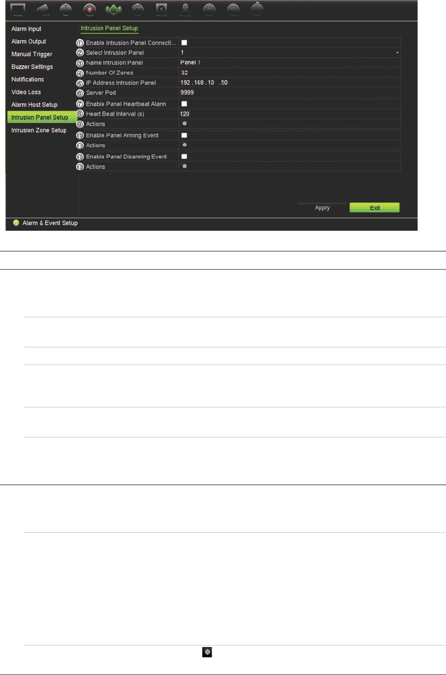
Chapter 13: Alarm and event setup
112 TruVision NVR 11 User Manual
Option Description
Set up the intrusion panel connection parameters:
1.
Enable Intrusion Panel
Connection Select this checkbox to enable the intrusion panel connection.
2. Select Intrusion Panel Select which panel you want to set-up. Up to three panels can
be set up.
3. Name Intrusion Panel Enter a name for the panel.
4. Number Of Zones Up to 32 panel zones can report to the recorder. The number
cannot be increased but you can allocate a different ID for each
zone under the “Intrusion Zone Setup” menu.
5. IP Address Intrusion Panel Enter the panel’s IP address. The IP address must be in the
same LAN as the recorder.
6. Server Port Enter the port that is used to report the events. Default is 9999.
This port number must match the port number set up in the
intrusion panel.
Set up the heartbeat alarm parameters:
7. Enable Panel Heartbeat
Alarm Select this checkbox to enable the panel heartbeat alarm. The
heartbeat alarm will then be reported to the recorder.
8. Heartbeat Interval (s) Enter the interval between two heartbeats. It is measured in
seconds. Default is 120 s. This interval is valid even if the
“Enable Panel Heartbeat Alarm” checkbox is disabled.
To be able to trigger a heartbeat alarm when the heartbeat is
not received within this interval, enable the “Enable Panel
Heartbeat Alarm” checkbox.
The recorder heartbeat interval must always be higher than that
of the intrusion panel.
9. Actions Click the button to set up the actions linked to the panel
heartbeat alarm. Go to step 3.
Set up the panel arming event parameters:
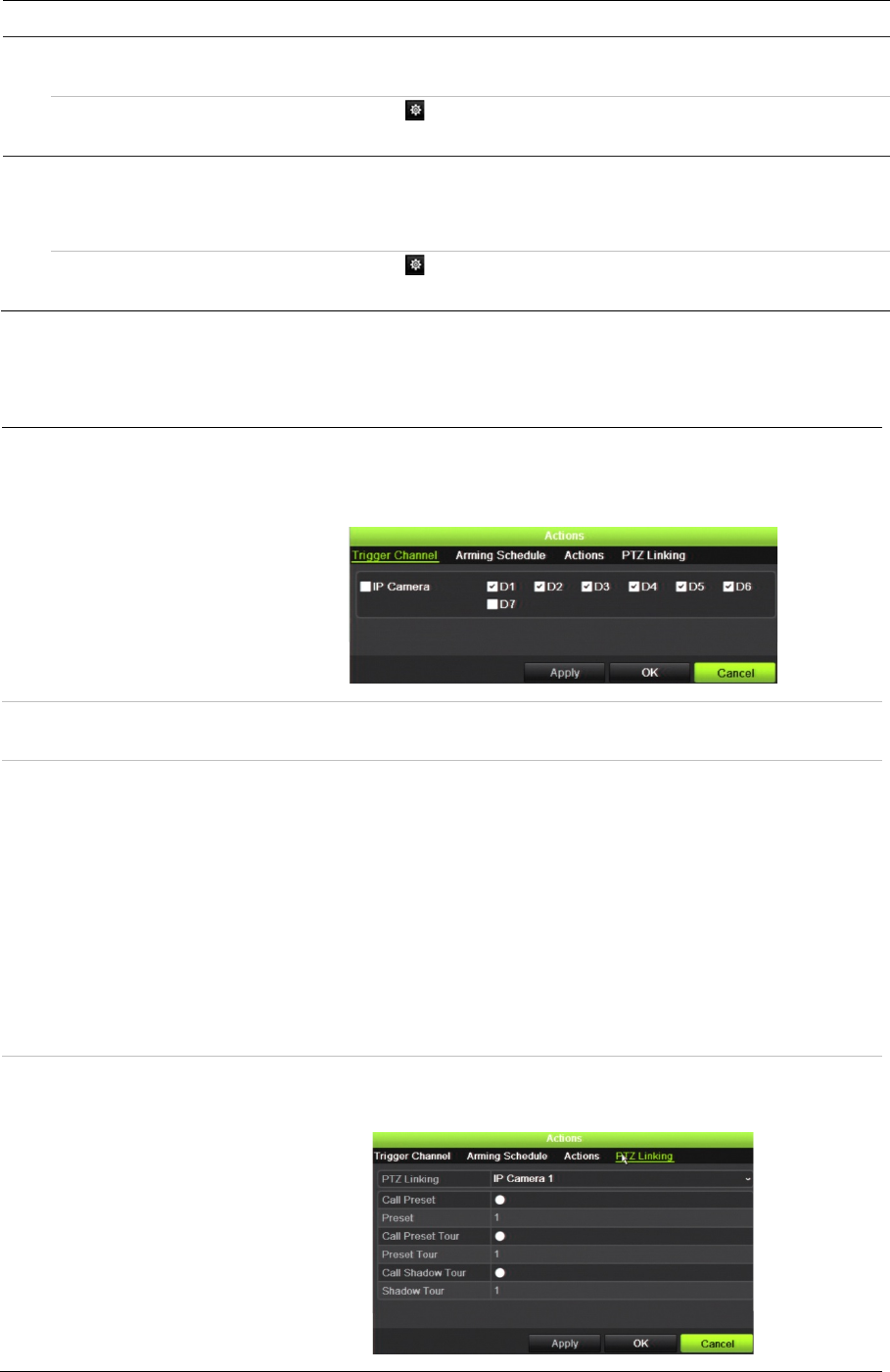
Chapter 13: Alarm and event setup
TruVision NVR 11 User Manual 113
Option Description
10. Enable Panel Arming Event Select this checkbox to enable the panel arming event. When
the panel is armed, it will be reported to the recorder.
11. Actions Click the button to set up the actions linked to the panel
arming alarm. Go to step 3.
Set up the panel disarming alarm parameters:
12. Enable Panel Disarming
Event Select this checkbox to enable the panel disarming event.
When the panel is disarmed, it will be reported to the recorder.
13. Actions Click the button to set up the actions linked to the panel
disarming alarm. Go to step 3.
3. To define the actions for the heartbeat, panel arm and panel disarm alarms that are
reported by the intrusion panel, click Action and each of the tabs:
Trigger Channel: Select the cameras that will record when an alarm event is received.
The cameras will record following the main stream (alarm) parameters.
The recordings will be 10 seconds for each assigned camera.
Arming Schedule: Define the alarm schedule for the actions. You can schedule up to
eight periods in a day. Default is 24 hours.
Actions: Check the required action that needs to be executed when an alarm is
received:
Full-screen Monitoring
Enable Alarm Audio
Notify the alarm host (supported by TruVision Navigator 7.0 and
higher)
Send Email
Upload Snapshots to FTP
Trigger Alarm Output
PTZ Linking: Select the PTZ camera as well as the preset, preset tour, or shadow
tour that is triggered when the alarm/event is detected.
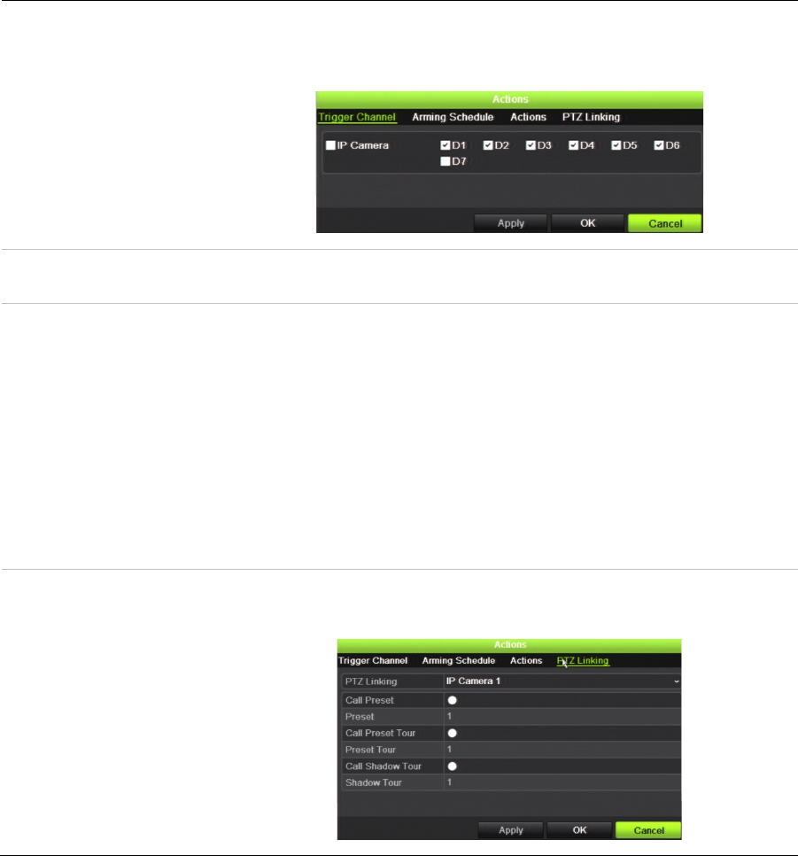
Chapter 13: Alarm and event setup
114 TruVision NVR 11 User Manual
Click Apply to save the settings. Click OK to return to the main window.
4. Click Apply to save the intrusion panel setup parameters.
5. Click Exit to return to live view.
To set up the zones in an alarm panel:
1. From the menu toolbar, click Alarm & Event Setup > Intrusion Zone Setup.
2. Under Select Intrusion Panel, select intrusion panel 1, 2 or 3.
3. Select the desired ID of a zone. The maximum is 32. The number does not have to
match the zone number.
4. Under Zone Number, select the desired zone number. The zone number can be
any valid number of the panel, which does not need to match the zone number.
5. Click Action to define the actions for the selected zone number.
Trigger Channel: Select the cameras that will record when an alarm event is received.
The cameras will record following the main stream (alarm) parameters.
The recordings will be 10 seconds for each assigned camera.
Arming Schedule: Define the alarm schedule for the actions. You can schedule up to
eight periods in a day. Default is 24 hours.
Actions: Check the required action that needs to be executed when an alarm is
received:
Full-screen Monitoring
Enable Alarm Audio
Notify the alarm host (supported by TruVision Navigator 7.0 and
higher)
Send Email
Upload Snapshots to FTP
Trigger Alarm Output
PTZ Linking: Select the PTZ camera as well as the preset, preset tour, and/or
shadow tour that is triggered when the alarm/event is detected.
Chapter 13: Alarm and event setup
TruVision NVR 11 User Manual 115
Click Apply to save the settings. Click OK to return to the main window.
6. Click Apply to save the intrusion panel setup parameters.
7. Click Exit to return to live view.
TVRMobile push notifications
TVRMobile 3.0 (and higher) can receive events from the recorder.
The ‘Push notifications’ feature lets TVRMobile notify a user of new messages or
events even when the user is not actively using TVRMobile.
In TVRMobile, events can be received from the recorder and these events can be
shown as a push notification to the user.
The recorder needs to be connected to the internet to be able to use push notifications.
Even when the phone or tablet is used via Wi-Fi on the same LAN as the recorder, an
internet connection is required. The reason is that push notifications need to use the
Android or Apple Notification Center for sending the messages to the mobile
application.
Set up push notifications
To set up push notifications in the recorder
1. In the browser or OSD set up an event for the desired camera.
2. In the Actions tab, enable Notify Alarm Host.
3. Under Alarm & Event Setup > Alarm Host Setup leave the destination address
empty.
4. Go to Network Settings > Network Settings.
5. Enter the DNS, IPv4 Default Gateway settings. Also enter the HHTP port, RTSP
service port and Server port settings.
HTTP port (default: 80) (*)
RTSP port (default: 554) (*)
Server port (default: 8000)
(*) Some ISPs block the use of port 80 and/or 554. When these ports are blocked,
use a port number higher than 1024.
To set up push notifications for TVRMobile:
1. In TVRMobile, add the recorder.
2. In the main menu, tap Alarm and then tap Set Alarm Notification.
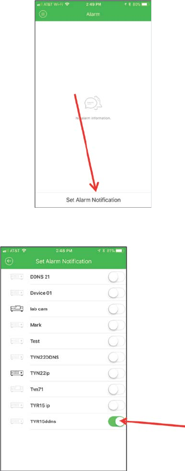
Chapter 13: Alarm and event setup
116 TruVision NVR 11 User Manual
3. Slide the button to the right to enable the push notification function for the recorder.
Display push notifications
1. When motion detection is detected, a red dot appears in the left upper corner of the
app icon with the number of triggers that have been detected. Tap the TVRMobile
app icon.
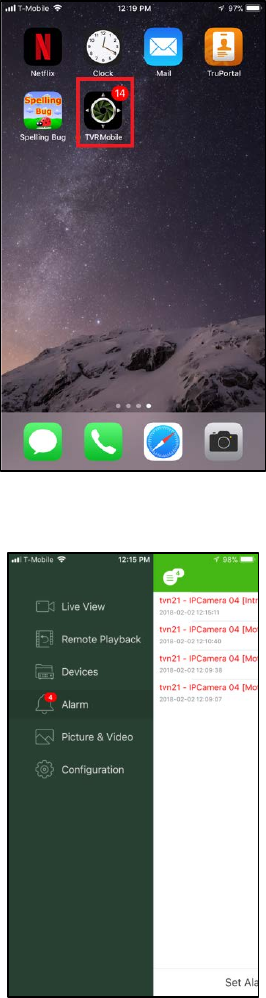
Chapter 13: Alarm and event setup
TruVision NVR 11 User Manual 117
2. Tap Alarm. A list of events appears.
3. Tap the camera icon next to an event.
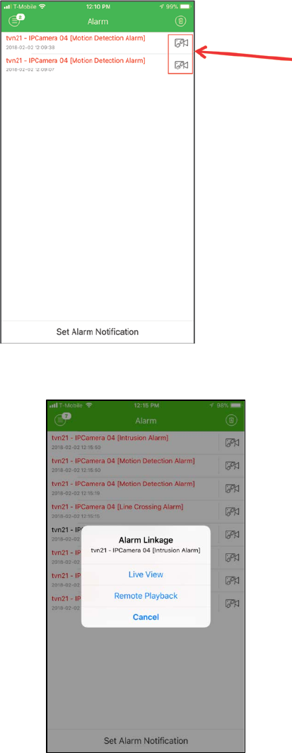
Chapter 13: Alarm and event setup
118 TruVision NVR 11 User Manual
4. Tap Live View or Remote Playback to view live or recorded video of the event.
TruVision NVR 11 User Manual 119
Chapter 14
Device management
This chapter describes how to:
Set up the time and date of the recorder
Select the recorder language and set up general system parameters such as the
device name, menu timeout period, and enable/disable password requirement
Import/export configuration files
Upgrade the firmware
Set up holiday periods
Enable RTSP, ISAIPISAPI and HTTP
Time and date settings
You can set up the date and time that will appear on-screen as well as on time stamped
recordings. The start and end time of daylight saving time (DST) in the year can also be
set. DST is deactivated by default. See Figure 29 below for the Time settings screen.
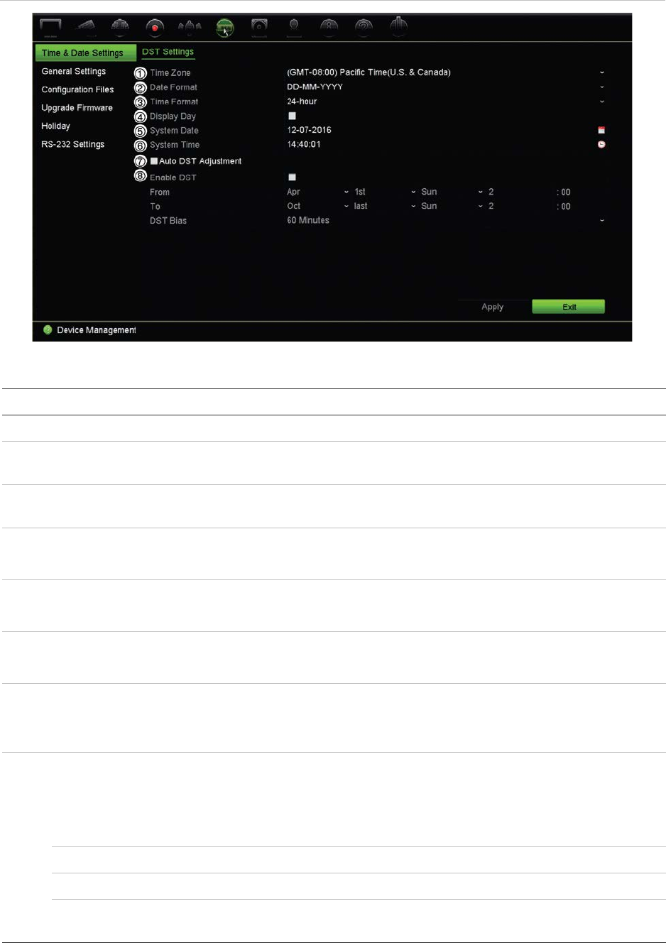
Chapter 14: Device management
120 TruVision NVR 11 User Manual
Figure 29: Time and Date Settings window
Table 14: Description of the Time and Date Settings window
Option Description
1.
Time Zone
Select a time zone from the list.
2.
Date Format
Select the date format from the drop-down list. Default format is DD-
MM-YYYY.
3.
Time Format
Select either the 12-hour or 24-hour time format from the list. Default
format is 24-hour format.
4.
Display Week
Select it to display the day of the week in the monitor time bar.
Select the checkbox to enable/disable. Default is Disabled.
5.
System Date
Enter the system date.
Default date is the current date.
6.
System Time
Enter the system time.
Default time is the current time.
7.
Auto DST Adjustment
Enable to activate DST is automatically. It depends on the time zone
selected.
Default is Disabled.
8.
Enable DST
Manually define DST. If this option is selected, the Auto DST
adjustment option is disabled.
Default is Disabled.
Click the checkbox to enable or disable daylight savings time (DST).
From
Enter the start date and time for daylight savings.
To
Enter the end date and time for daylight savings.
DST Bias
Set the amount of time to move DST forward from the standard time.
Default is 60 minutes.
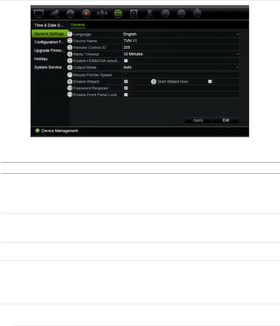
Chapter 14: Device management
TruVision NVR 11 User Manual 121
General recorder settings
Use the General Settings menu of Device Management to configure general recorder
options.
See Figure 30 below for the general options available. The changes are immediately
implemented once Apply is clicked to save the settings.
Figure 30: General Settings of the recorder
Table 15: Description of the General Settings window
Option Description
1.
Language
Define the language of the system.
Select the desired language from the drop-down list and click Apply. The
language displayed changes immediately.
Default is English.
2.
Device Name
Define the recorder name.
Click the edit box and enter the new name from the soft keyboard. Default
is TVN 11.
3.
Remote Control ID
The device number to use for the recorder when linking the device to a
remote control. The default value is 255.
4.
Menu Timeout
Define the time in minutes after which the menu window reverts to live
view mode. Select a time from the drop-down list, and click Apply. Menu
timeout also applies to the system idle time after which a password will be
required.
Default value is 5 minutes.
5.
Enable HDMI/VGA
Simultaneous Output
8- and 16-channel recorders only:
Both HDMI and VGA monitors display the same content simultaneously.

Chapter 14: Device management
122 TruVision NVR 11 User Manual
Option Description
6.
Output Mode
4-channel recorder:
Default option is Auto. The system then automatically detects which type
of monitor is connected to the recorder.
8- and 16-channel recorders:
Select Auto, HDMI, or VGA as the main monitor. If Auto is selected, the
recorder will detect the connected monitor and use that as the main
monitor. You will also not be able to change the main and event monitor
options in the Display Settings > Display window.
7.
Mouse Pointer Speed
Modify the speed of the mouse pointer. Adjust the scroll bar point to the
desired level and click Apply. Slowest speed is to the left of the scroll bar.
Default is the slowest of the four speeds.
8.
Enable Wizard
Immediately start the Startup Wizard without rebooting the system.
Select the checkbox to enable/disable and click Apply.
Default is Enabled.
9.
Start Wizard Now
Reboot the system immediately and start the Startup Wizard.
Default is Enabled.
10.
Password Required
Define whether a login password is required to open the menu.
Select the checkbox to enable/disable and click Apply.
Default is Enabled.
11.
Enable Front Panel Lock
When the system logs out, the front panel is automatically locked.
When enabled, to unlock the front panel, press the Live button for 5
seconds.
Default is Disabled.
Configuration files
You can export and import configuration settings from the recorder. This is useful if you
want to copy the configuration settings to another recorder, or if you want to make a
backup of the settings.
You cannot import a configuration file if the firmware version of the recorder has in the
meantime changed.
Import and export files
Insert an external storage device in the recorder. Go to the Device Management >
Configuration Files to import or export configuration settings. Click Export to export
the recorder’s configuration settings into an external storage device or click Import to
import configuration settings after selecting a configuration file from the external storage
device.
Chapter 14: Device management
TruVision NVR 11 User Manual 123
Restore default settings
The administrator can reset the recorder to the factory default settings. Network
information such as IP address, subnet mask, gateway, MTU, NIC working mode,
server port, and default route are not restored to factory default settings.
To restore parameters to default factory settings:
1. From the menu toolbar, click Device Management > Configuration Files.
Note: Only the administrator can restore the default settings.
2. To restore all parameters to default factory settings:
Click the Default button. Enter the Admin password, click OK, and then click Yes to
confirm that you want to restore all parameters to default.
Or
To restore all parameters, except network settings, to default factory settings:
Click the Restore button. Enter the Admin password, click OK, and then click Yes to
confirm that you want to restore all parameters except network settings to default.
3. Click OK to confirm you want to restore default settings.
The system will restart.
Upgrade system firmware
The firmware on the recorder can be updated using three methods:
Via a USB device
Via the recorder web browser
Using TruVision Navigator. For further information, refer to the TruVision Navigator
user manual.
The firmware upgrade file is labeled TVN11.dav.
To update the system firmware using a USB device:
1. Download the latest firmware from our web site at:
www.interlogix.com
For EMEA, go to www.firesecurityproducts.com
2. Connect the USB device to the recorder.
3. From the menu toolbar, click Device Management > Upgrade Firmware.
The list of files on the USB is displayed.
4. Select the firmware file and click Upgrade. Click Yes to begin the upgrade process.
5. When the upgrade process is completed, reboot the recorder. The recorder does
not reboot automatically.
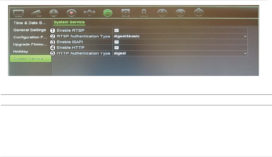
Chapter 14: Device management
124 TruVision NVR 11 User Manual
Holiday schedules
It is possible to indicate holidays for which you can create a separate recording
schedule. Once one or more holidays are created, a separate entry for Holiday will be
included in the recording schedule (refer to “Recording schedule” on page 99 of the
manual)
To set up a holiday recording schedule:
1. From the menu toolbar, click Device Management > Holiday.
2. Select a holiday period from the list and click its Edit button to modify the settings.
The Edit window appears.
3. Enter the name of the holiday period and click Enable.
4. Select whether the holiday period will be categorized by date, week, or month and
then enter the start and end dates.
5. Click Apply to save the settings and then OK to return to the Edit window.
6. Repeat steps 2 to 5 for other holiday periods.
7. Click Exit to return to live view.
System service
Use the System Service menu to enable/disable the RTSP, ISAPI, and HTTP
protocols.
Figure 31: System service window
Table 16: Description of the system service window
Option Description
1.
Enable RTSP
TruVision recorders utilize Real Time Streaming Protocol (RTSP) for
transmitting live and playback video to users. Disabling this
parameter will stop all video streaming from the recorder.
This should be left at its default value unless otherwise instructed by
the system administrator.
This function is available via both the OSD and web.

Chapter 14: Device management
TruVision NVR 11 User Manual 125
Option Description
2.
RTSP Authentication Type
The administrator can set the authentication for accessing RTSP
streams with this dropdown menu.
This should be left at its default value unless otherwise instructed by
the system administrator, as choosing the wrong value will negatively
impact performance.
This function is only available via the OSD.
3.
Enable ISAPI
ISAPI is an application programming interface used by the recorders
to communicate with certain software platforms.
It should be left at its default setting unless otherwise indicated by the
system administrator.
This function is only available via the OSD.
4.
Enable HTTP
Hypertext Transfer Protocol (HTTP) is the protocol utilized for various
communications to and from the recorder. Disabling this feature
effectively locks down all HTTP communications, making it
inaccessible remotely over the network.
It should be left a
t its default setting unless otherwise indicated by the
system administrator.
This function is only available via the OSD.
5.
HTTP Authentication Type
The administrator can set the method for authentication used by the
web interface.
This should be left at its default value unless otherwise instructed by
the system administrator, as choosing the wrong value will negatively
impact performance.
This function is only available via the OSD.
126 TruVision NVR 11 User Manual
Chapter 15
Storage management
This chapter describes the content of the Storage Management menu, including HDD
information, storage mode, S.M.A.R.T. settings as well as bad sector detection.
HDD status information
You can check the status of any of the installed HDDs on the recorder at any time.
To check the status of a HDD:
1. From the menu toolbar, click Storage Management > HDD Information.
2. Note the status of the HDDs listed under the Status column.
If the status is listed as Normal or Sleeping, the HDD is in working order. If it is listed
as Abnormal and has already been initialized, the HDD needs to be replaced. If the
HDD is Uninitialized, you need to initialize it before it can be used in the recorder.
Refer to “Initialize a HDD” below for more information.
Note: The status information is also shown in the System Information > HDD window.
Initialize a HDD
The built-in HDD does not need to be initialized before it can be used. You can also re-
initialize the HDD. However, all data on the HDD will be destroyed.
To initialize a HDD:
1. From the menu toolbar, click Storage Management > HDD Information.
2. In the HDD Information window, select the HDD to be initialized.
3. Click the Initialize button to begin initialization.
After the HDD has been initialized, the status of the HDD changes from Abnormal to
Normal.

Chapter 15: Storage management
TruVision NVR 11 User Manual 127
Overwrite a HDD
You can select how the recorder responds when the HDDs become full and there is no
longer sufficient space to save new data. The overwrite option is enabled by default.
To enable overwrite when the HDDs are full:
1. From the menu toolbar, click Storage Management > HDD Information.
2. Enable Overwrite.
Caution: If the overwrite option is disabled and the quota management capacity for
a channel is set to zero, the recordings on that channel can still be overwritten. To
avoid this happening, set a quota level for the channel.
3. Click Apply to save the settings.
4. Continue to configure the recorder or click Exit to return to live view.
Add a HDD
You can add additional network-attached hard drives to setup a NAS or SAN system.
Up to eight disks can be added.
To add a HDD:
1. From the menu toolbar, click Storage Management > HDD Information.
2. Click the Add button to begin.
3. Select a Network Storage name from the drop-down list.
4. Select the network storage type. Select NAS or IP SAN.
Note: Only NAS with NFS version 3.0 or higher is supported. The NAS must be able
to be used without login credentials.
5. Enter the HDD storage IP address.
6. Enter the network storage directory so that the recorder knows where to place the
files.
7. Click the Search button to search for the Storage Directory.
8. Click the OK button to create the selected network attached storage and to return to
the HDD Information window.
Storage mode
To ensure an efficient use of the storage space available on HDDs, you can control an
individual camera’s storage capacity using HDD quota management. This function lets
you allocate different storage capacities for both recordings and snapshots to each
camera.
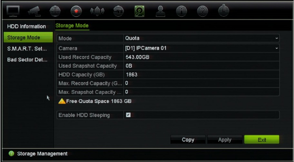
Chapter 15: Storage management
128 TruVision NVR 11 User Manual
Note: If the overwrite function is enabled, the maximum capacity for both recordings
and snapshots is set to zero by default.
To set the HDD quota for a camera:
1. From the menu toolbar, click Storage Management > Storage Mode.
2. Under Mode, select Quota.
3. Select a camera whose storage capacity you want to change and enter the values in
GB for the maximum record capacity and snapshot capacities. The available quota
space available is displayed on screen.
4. Click Apply to save the settings.
5. If you want to copy these values to other cameras, click Copy and select each
camera individually. Click OK. Click Apply to save the settings.
Set up HDD sleep mode
You can set the HDD to enter standby mode, or sleep mode, after a period of inactivity.
Sleep mode decreases the power consumption of a HDD.
To enable HDD sleep mode:
1. From the menu toolbar, click Storage Management > Storage Mode.
2. Check Enable HDD Sleeping to enable sleep mode. Default is Enabled.
3. Click Apply to save the settings.
4. Continue to configure the recorder or click Exit to return to live view.
S.M.A.R.T. settings
S.M.A.R.T. (Self-Monitoring, Analysis and Reporting Technology) reports on a variety of
hard drive attributes. It helps ensure that the HDD is functioning properly at all times
while protecting video stored on the hard drive.
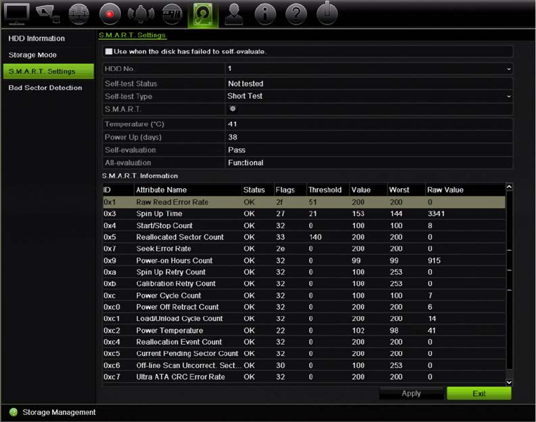
Chapter 15: Storage management
TruVision NVR 11 User Manual 129
To view the S.M.A.R.T. information of a HDD:
1. From the menu toolbar, click Storage Management > S.M.A.R.T. Settings.
2. Select the HDD whose data you want to see. A detail listing of S.M.A.R.T.
information is displayed.
3. If you want to continue to use a HDD when the S.M.A.R.T. test has failed, select the
checkbox Use when the disk has failed to self-evaluate. Click Apply to save the
settings.
4. Click Exit to return to live view.
Bad sector detection
You can improve the performance of your HDDs by ensuring that they have no bad
sectors. Bad sectors can slow down an HDD when reading or writing data, for example.
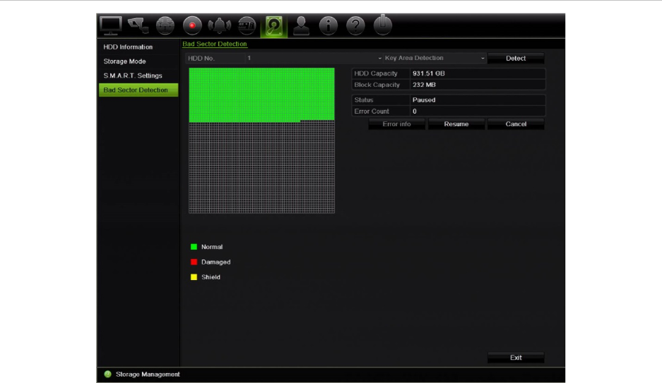
Chapter 15: Storage management
130 TruVision NVR 11 User Manual
Figure 32: Bad sector detection window
To detect bad sectors:
1. From the menu toolbar, click Storage Management > Bad Sector Detection.
2. Select the HDD you want to test.
3. Select whether you want to do a key area detection or a full detection, and click
Detect.
4. The system checks the HDD. The color-coded result is displayed on screen. If there
are bad sectors found, click Error Info to see a list of the errors found.
5. If required, click Pause to pause the test or Cancel to cancel it.
6. Click Exit to return to live view.

TruVision NVR 11 User Manual 131
Chapter 16
User management
Add a new user
Only a system administrator can create a user. You can have a maximum of 16 users
(the administrator as well as operators and guests).
To add new users:
1. From the menu toolbar, click User Management.
2. Click Add to enter the Add User window.
3. Enter the new user’s name and password. Both the user name and password can
have up to 16 alphanumeric characters.
4. Select the new user’s access level: Operator or Guest. Default is Guest.
Operator The Operator account includes reduced menu access to Video
settings (inaccessible features are not visible).
Guest The Guest account includes menu access with no
programming possibilities (inaccessible features are not
visible). Can see live view and access playback.
5. Enter the user’s MAC address to let the user access the recorder from a remote
computer with this MAC address.
6. Click OK to save the settings and return to the previous window.
7. Define the user’s permissions.
Click the Permission button for the new user. In the Permissions pop-up
window check the required access privileges for local, remote, and camera
configuration. See “Customizing a user’s access privileges” below for the permission
descriptions for each group.
Click Apply to save the settings and OK to return to the previous window.
8. Click Exit to return to live view.
Chapter 16: User management
132 TruVision NVR 11 User Manual
Customize a user’s access privileges
Only an administrator can allocate access privileges to Operator and Guest users. The
access privileges can be customized for each user’s needs. The administrator’s access
privileges cannot be changed.
There are three types of privilege settings: Local Configuration, Remote Configuration,
and Camera Configuration.
Note: Only the administrator can restore factory default settings.
Local configuration settings
By default, only the local information (log) management setting is enabled for both
operators and guests.
• Local Information (Log) Management: Search and view logs of the recorder and
view system information.
• Local Parameter Settings: Configure parameters and import the configuration from
the recorder.
• Local Camera Management: Locally add, delete, and edit IP cameras.
• Local Advanced Operation: Access HDD management (including the initialization
and modification of disk properties). Update system firmware as well as stop the I/O
alarm output.
• Local Shutdown/Reboot: Shutdown or reboot the recorder.
Remote configuration settings
By default, only remote log search and bi-directional audio are enabled for operators,
and only the remote log search is enabled for guests.
• Remote Log Search: Remotely view logs that are saved on the recorder.
• Remote Parameter Settings: Remotely configure parameters and import
configuration.
• Remote Camera Management: Remotely enable and disable channels.
• Remote Video Output Control: For future use.
• Bi-directional Audio: Use bi-directional audio between the remote client and the
recorder.
• Remote Notify Surveillance Center/Trigger Alarm Output: Remotely alert or
control the relay output of the recorder. Alarm and notification settings must be
configured properly to upload to surveillance center.

Chapter 16: User management
TruVision NVR 11 User Manual 133
• Remote Advanced Operation: Remotely manage HDDs (initializing and setting
properties for HDDs) as well as remotely update system firmware and clear the I/O
alarm output.
• Remote Shutdown/Reboot: Remotely shutdown or reboot the recorder.
Camera configuration settings
By default, all cameras are enabled for operators for each of these settings. By default,
the cameras are only enabled for local playback and remote playback for guests.
• Local Live View: Locally select and view live video.
• Local Playback: Locally play recorded files that are on the recorder.
• Local Manual Operation: Locally start/stop manual recording on any of the
channels, snapshots, and video clips.
• Local PTZ Control: Locally control PTZ dome cameras.
• Local Video Export: Locally back up recorded files from any of the channels.
• Remote Live View: Remotely select and view live video over the network.
• Remote Playback: Remotely play and download recorded files that are on the
recorder.
• Remote Manual Operation: Remotely start/stop manual recording on any of the
channel.
• Remote PTZ Control: Remotely control PTZ dome cameras.
• Remote Video Export: Remotely backup recorded files from any channel.
• Remote Video Download: Remotely download video.
To customize a user’s access privileges:
1. Click the User Management icon in the menu toolbar to display its window.
2. Click the Permission button for the user whose access privileges need to be
changed. The Permissions pop-up window appears.
3. Click Apply to save the settings.
4. Click the OK button to return to the previous window.
5. Click Exit to return to live view.
Delete a user
Only a system administrator can delete a user.

Chapter 16: User management
134 TruVision NVR 11 User Manual
To delete a user from the recorder:
1. Click the User Management icon in the menu toolbar to display its window.
2. Click the Delete button for the user to be deleted.
3. Click Yes in the pop-up window to confirm deletion. The user is immediately
deleted.
4. Click Exit to return to live view.
Modify a user
A user’s name, password, access level and MAC address can be changed. Only a
system administrator can modify a user.
To modify a user:
1. Click the User Management icon in the menu toolbar to display its window.
2. Click the Edit button for the user whose details need to be changed. The Edit
User pop-up window appears.
3. Edit the user information and click OK to save the settings and return to the
previous window.
4. Click Exit to return to live view.
Change the Admin password
The administrator’s password can be changed in the User Management menu.
To change the admin password:
1. Click the User Management icon in the menu toolbar to display its window.
2. Click the Edit button for admin. The Edit User pop-up window appears.
3. Edit the current admin password and select the Change Password checkbox.
4. Enter the new admin password and confirm it. Change the admin MAC address, if
required. Click OK to save the settings and return to the previous window.
5. Click Exit to return to live view.
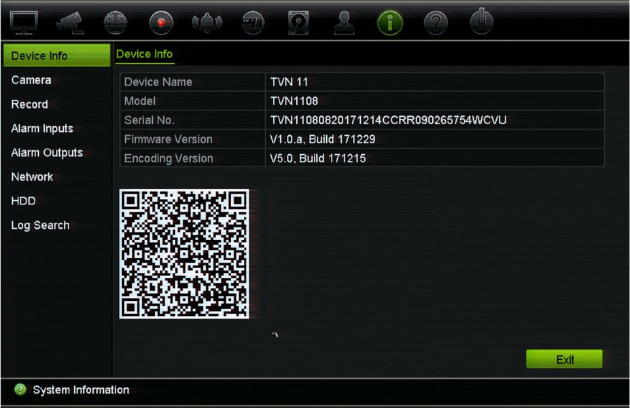
TruVision NVR 11 User Manual 135
Chapter 17
System information
View system information
To view system information:
1. From the menu toolbar, click System Information.
2. To view device information, click Device Info.
You can view the device name, model, serial number, firmware version, and
encoding version. The QR code for the recorder is also displayed.
You can quickly enter the recorder parameters into TVRMobile by scanning the QR
code.
Note: The TVRMobile app must first be installed on your smart phone before
scanning the recorder QR code.
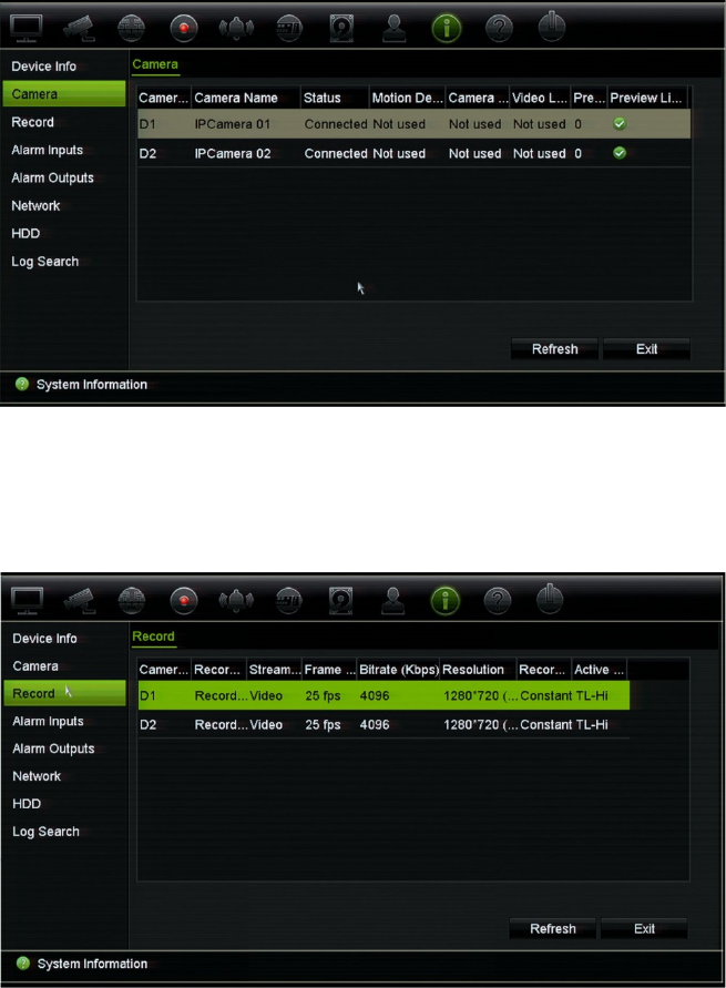
Chapter 17: System information
136 TruVision NVR 11 User Manual
3. To view camera information, click Camera.
You can view the information on each camera: camera number, camera name,
status, motion detection, tamper proof, video loss, preview link sum, and preview
link information.
Preview link sum shows the amount of rote applications that are streaming video
from this video channel. Preview link information shows you the IP addresses that
are currently connected to this channel.
4. To view record information, click Record.
You can view the camera number, recording status, stream type, frame rate, bit rate
(Kbps), resolution, record type, active schedule.
5. To view alarm input information, click Alarm Inputs.
You can view the alarm input number, alarm name, alarm type, alarm status, and
the triggered camera.
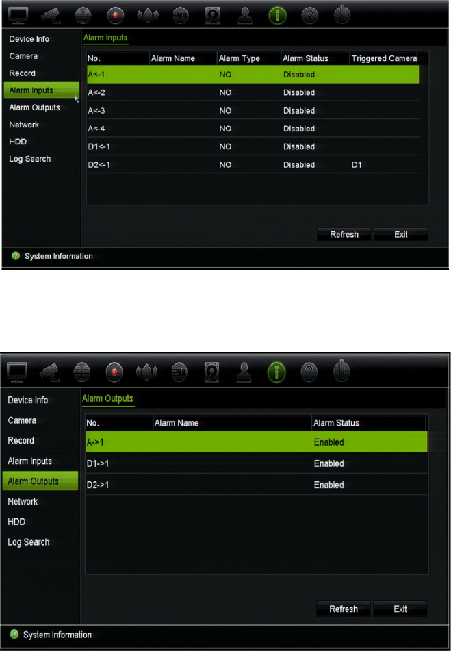
Chapter 17: System information
TruVision NVR 11 User Manual 137
6. To view alarm output information, click Alarm Outputs.
You can view the alarm output number, alarm name, and alarm status.
7. To view network information, click Network.
You can view the IPv4 address, IPv4 subnet mask, IPv4 default gateway, IPv6
address 1, IPv6 address 2, IPv6 default gateway, MAC address, preferred DNS
server, alternate DNS server, enable DHCP, and enable PPPoE,

Chapter 17: System information
138 TruVision NVR 11 User Manual
8. To view HDD information, click HDD.
You can view the HDD label, status, capacity, free space, property, type, and group.
The recorded time (how many days we have recordings on the HDD) is also shown.
9. Click Exit to return to live view.
Search the system log
Many events of the recorder, such as operation, alarm, information, and notification are
logged into the system logs. They can be viewed and exported at any time.

Chapter 17: System information
TruVision NVR 11 User Manual 139
Up to 2000 log files can be viewed at once.
Log files can also be exported onto a USB device. The exported file is named according
to the time it was exported. For example: 20180219124841logBack.txt.
Note: Connect the backup device, such as a USB flash drive, to the recorder before
commencing the log search.
To search video from the system log:
1. From the menu toolbar, click System Information > Log Search.
2. Select the search start and end date and times.
3. Under Event, select an option from the drop-down list: All, Alarm, Notification,
Operation, or Information.
4. From the Type list, select one of the options:
Event Type
All All
Alarm All, Alarm Input, Alarm Output, Start Motion Detection, Stop Motion Detection,
Start Camera Tamper, Stop Camera Tamper, Cross Line Alarm Started, Cross
Line Alarm Stopped, Intrusion Alarm Detection Started, Intrusion Alarm Detection
Stopped, Audio Input Exception Alarm Started, Audio Input Exception Alarm
Stopped, Sudden Change of Sound Intensity Alarm Started, Sudden Change of
Sound Intensity Alarm Stopped, Face Detection Alarm Started, Face Detection
Alarm Stopped, Defocus Detection Alarm Started, Defocus Detection Alarm
Stopped, Scene Change Alarm Started, Scene Change Alarm Stopped, Enter
Region Alarm Started, Enter Region Alarm Stopped, Exit Region Alarm Stopped,
Exit Region Alarm Stopped, Object Left Behind Alarm Started, Object Left Behind
Alarm Stopped, Object Removed Alarm Started, Object Removed Alarm
Stopped, Intrusion Arming Panel Event Started, Intrusion Disarming Panel Event
Started, Intrusion Event Alarm Started, Intrusion Panel Heartbeat Alarm Started
Notification All, Video Loss Alarm, Illegal Login, HDD Full, HDD Error, Duplicate IP Address
Found, Network Disconnected, Abnormal Record, IP Camera Disconnected, IP
Camera Address Conflicted, IP Camera Access Exception, Record Buffer
Overflow, EFR Record, Exception, IP Camera Motion Analysis Exception
Operation All, Power Up, Local: Shutdown, Abnormal Shutdown, Watchdog Reboot, Local:
Restart, Local: Login, Local: Logout, Local: Configure Parameters, Local:
Upgrade, Local Operation: Restore Defaults, Local Operation: Factory Defaults,
Local: Start Manual Recording, Local: Stop Manual Recording, Local: PTZ
Control, Local: Lock File, Local: Unlock File, Local: Trigger Alarm Output, Local:
Initialize HDD, Local: Add IP Camera, Local: Delete IP Camera, Local: Set IP
Camera, Local: Upgrade IP Camera Firmware, Local: Import IP Camera File,
Local: Export IP Camera File, Local: Playback by File, Local: Playback by Time,
Local: Export Config File, Local: Import Config File, Local: Export Record File,
Local: Export Snapshot File, Local: Add Network Storage, Local: Delete Network
Storage, Local: Set Network Storage, Local: Restore Admin’s Password, Local:
Operate Bookmark, Local: Switch Output, Local: HDD Detect, Local: Delete HDD,
Local: Configure SNMP, Quick Snapshot, Remote: Shutdown, Remote: Reboot,
Remote: Login, Remote: Logout, Remote: Configure Parameters, Remote:
Upgrade, Remote Operation: Restore Defaults, Remote Operation: Factory
Defaults, Remote: Start Manual Recording, Remote: Stop Manual Recording,
Remote: PTZ Control, Remote: Lock File, Remote: Unlock File, Remote: Trigger
Alarm Output, Remote: Initialize HDD, Remote: Add IP Camera, Remote: Delete
IP Camera, Remote: Set IP Camera, Remote: Upgrade IP Camera Firmware,
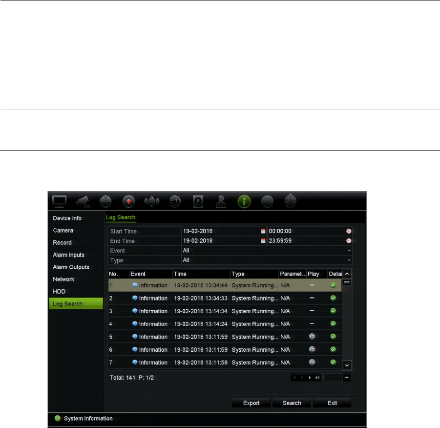
Chapter 17: System information
140 TruVision NVR 11 User Manual
Remote: Import IP Camera File, Remote: Export IP Camera File, Remote:
Playback by File, Remote: Playback by Time, Remote: Download by File,
Remote: Download by Time, Remote: Export Config File, Remote: Import Config
File, Remote: Export Record File, Remote: Export Snapshot File, Remote: Get
Parameters, Remote: Get Working Status, Connect Transparent Channel,
Disconnect Transparent Channel, Start Bi-directional Audio, Stop Bi-directional
Audio, Remote: Alarm Arming, Remote: Alarm Disarming, Remote: Add Network
Storage, Remote: Delete Network Storage, Remote: Set Network Storage,
Remote: Operate Bookmark, Remote: Delete HDD, Remote: Configure SNMP
Information All, Local HDD Information, HDD S.M.A.R.T., Start Recording, Stop Recording,
Delete Expired Video File, Network Storage Information, System Running Status,
EFR Record Started, EFR Record Stopped, Add IP Camera EFR Time Duration
5. Click the Search button. A list of results appears.
6. Select a file and click:
- Details: Displays information on the log or recording. For a recording, it lists such
information as start time, type of event, local user, host IP address, parameter type,
camera number, and gives a description on the types of events recorded and when
record time was stopped.
- Play: Click to start playback of the selected recording.
7. Click Export to archive the selected file to a USB flash device. The Export window
appears. Select the device name of the USB flash drive, and file type to save. The
default file type is *.txt. Click Export to export the select file to the USB flash drive.
8. Click Exit to return to live view.
TruVision NVR 11 User Manual 141
Chapter 18
Using the web browser
This chapter describes how you can use the web browser interface to configure the
device, play back recorded video, search through event logs, and control a PTZ dome
camera. You can also specify settings on the web browser interface to optimize video
playback and recording performance when operating in a low or limited bandwidth
environment. Many of the browser configurations are similar to those done locally.
Internet Explorer users
Internet Explorer for Windows operating systems have increased security measures to
protect your PC from any malicious software being installed. When using the recorder
web browser interface, you can install ActiveX controls to connect and view video using
Internet Explorer.
To have complete functionality of the web browser interface and the recorder player
with Internet Explorer, do the following:
• Run the Browser interface and the recorder player application as an administrator in
your workstation
• Add the recorder’s IP address to your browser’s list of trusted sites
To add the recorder’s IP address to Internet Explorer’s list of trusted sites:
1. Open Internet Explorer.
2. Click Tools, and then Internet Options.
3. Click the Security tab, and then select the Trusted Sites icon.
4. Click Sites.
5. Clear the “Require server verification (https:) for all sites in this zone” box.
6. Enter the IP address or DDNS name in the “Add this website to the zone” field.
7. Click Add, and then click Close.
8. Click OK in the Internet Options dialog box.
9. Connect to the recorder for full browser functionality.

Chapter 18: Using the web browser
142 TruVision NVR 11 User Manual
Access the web browser
To access the recorder, open the Microsoft Internet Explorer web browser and enter the
IP address assigned to the recorder, as a web address. On the logon window, enter the
user ID and password.
Install the recorder web plug-in to see live camera images.
Note: Only one recorder can be viewed per browser.
The default values for recorder network settings are:
• DHCP: Disabled by default.
• IP address - 192.168.1.82
• Subnet mask - 255.255.255.0
• Gateway address - 192.168.1.1
• Server port: 8000
• Ports: The following ports need to be forwarded in the router in order to connect
properly
When using the browser:
RTSP port: 554
HTTP port: 80
When using TruNav:
RTSP port: 554
Server/Client software port: 8000
For more information on port forwarding, see Appendix B “Port forwarding information”
on page 156.
HTTPS settings
Using HTTPS (Hypertext Transfer Protocol Secure) is a secure protocol that provides
authenticated and encrypted communication. It ensures that there is a secure private
channel between the recorder and cameras
You can create self-signed server certificates as well as request certified server
certificates to ensure your network security.
To create a certificate:
1. Go to Configuration > Network Settings > HTTPS of the browser.
2. Click “Create Self-Signed certificate”.
3. Type in the country, hostname/IP address, and days of validity (there are more
parameters, but you don’t need to add anything to them).
4. Click OK.
5. Check “Enable HTTPS”.

Chapter 18: Using the web browser
TruVision NVR 11 User Manual 143
This only works if you enter the address in the browser as HTTPS (as in
https://192.168.1.70).
6. Click through the warning you get on the browser.
Buy a certificate:
1. Go to the Configuration > Network Settings > HTTPS section of the browser.
2. Click “Create Certificate Request” and fill out the parameters that appear.
3. Click OK.
4. Click “Download” next to the request that you just created in the browser, and get a
.csr file.
5. Visit a site like https://www.startssl.com/?app=1 and upload your .csr file to get a
trusted certificate.
For larger companies, a corporate certificate might be available from the IT department.
Web browser live view
The recorder web browser lets you view, record, and play back videos as well as
manage all aspects of the recorder from any PC with Internet access. The browser’s
easy-to-use controls give you live view to all the recorder functions. See Figure 33 on
page 144.
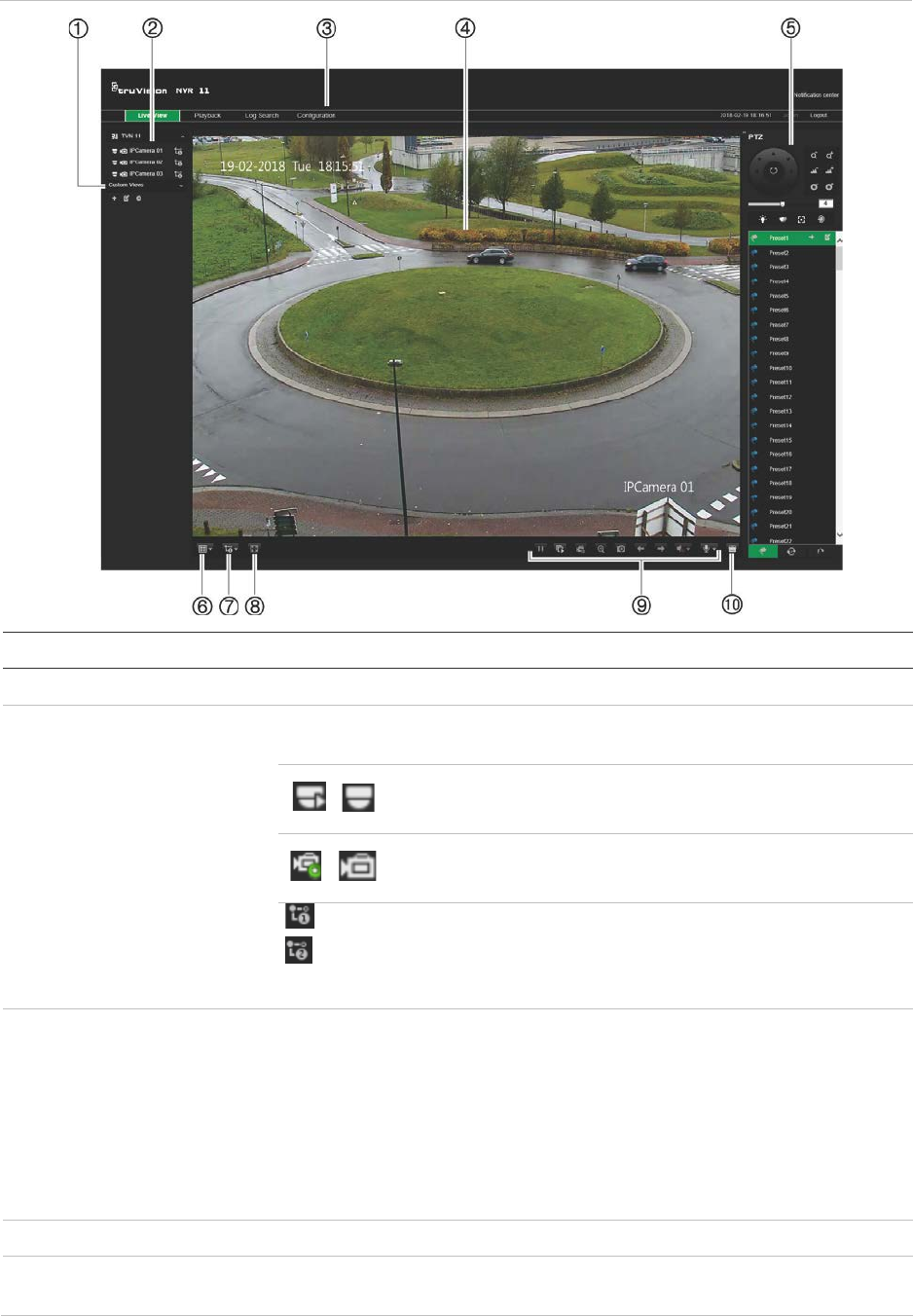
Chapter 18: Using the web browser
144 TruVision NVR 11 User Manual
Figure 33: Live view in the web browser interface
Name Description
1
. Custom view Lets you group selected cameras together in live view.
2
. Camera live view and
recording Select the camera for live viewing and recording as well as the
streaming type.
/ Click the button to start/stop live view from the selected
camera.
/ Click the button to start/stop local recording on your PC
from the selected camera.
Main stream (1)
Substream (2)
Position the mouse cursor on the streaming
type button and select the desired stream
from the pop-up menu: Main stream or
Substream.
3
. Menu toolbar Lets you navigate through the following menus:
• View live video
• Play back video
• Search for event logs
• Configure settings
• Log out of the interface
4
. Viewer View live or playback video.
5
. PTZ/Video parameters
panel Hide/display the PTZ panel.
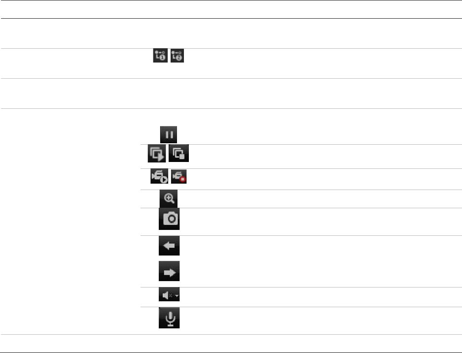
Chapter 18: Using the web browser
TruVision NVR 11 User Manual 145
Name Description
6
. Display format Define how you want video to be displayed in the viewer: Single or
multiview.
7
. Streaming type Select main stream (1) and substream stream (2) for all the
cameras.
8
. Full screen Display the video tiles only. Toolbars and panels not displayed. Press
ESC button on the keyboard to view toolbars and panels.
9
. Video function toolbar Lets you do the following in live view:
Pause live viewing.
Start/stop live streaming from all cameras.
Start/stop local recording from all cameras.
Digital zoom.
Take a snapshot.
View previous and next camera respectively.
If viewing in multiview format, live view moves to the next
group of cameras for the selected number of video tiles.
Turn audio on/off
Turn microphone on/off
10
. Alarm output Shows the alarm outputs of the recorder and lets you trigger them on/off
Control a PTZ dome camera via the web browser
The web browser interface lets you control the PTZ functions of a dome camera. Click a
PTZ dome camera and use the PTZ controls on the interface to control the PTZ
functions.
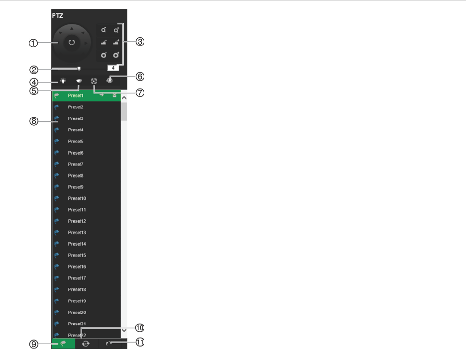
Chapter 18: Using the web browser
146 TruVision NVR 11 User Manual
Figure 34: PTZ controls
1. Directional pad/auto-scan buttons: Controls the
movements and directions of the PTZ. Center button is
used to start auto-pan by the PTZ dome camera.
2. Adjust speed of PTZ dome camera.
3. Adjust zoom, focus, and iris.
4. Turn on or off the camera light (if available on the camera).
5. Start or stop camera wiper (if available on the camera).
6. Lens initialization: Initialize the lens of a camera with a
motorized lens, such as PTZ or IP cameras. This function
helps to maintain lens focus accuracy over prolong periods
of time.
7. Auxiliary focus: Automatically focus the camera lens for the
sharpest picture.
8. Start selected preset/tour/shadow tour (depending on
function selected).
9. List presets available.
10. List preset tours available.
11. List shadow tours available.
Play back recorded video
To search and play back recorded video, click Playback on the menu bar to display the
Playback page shown in Figure 35 on page 147.
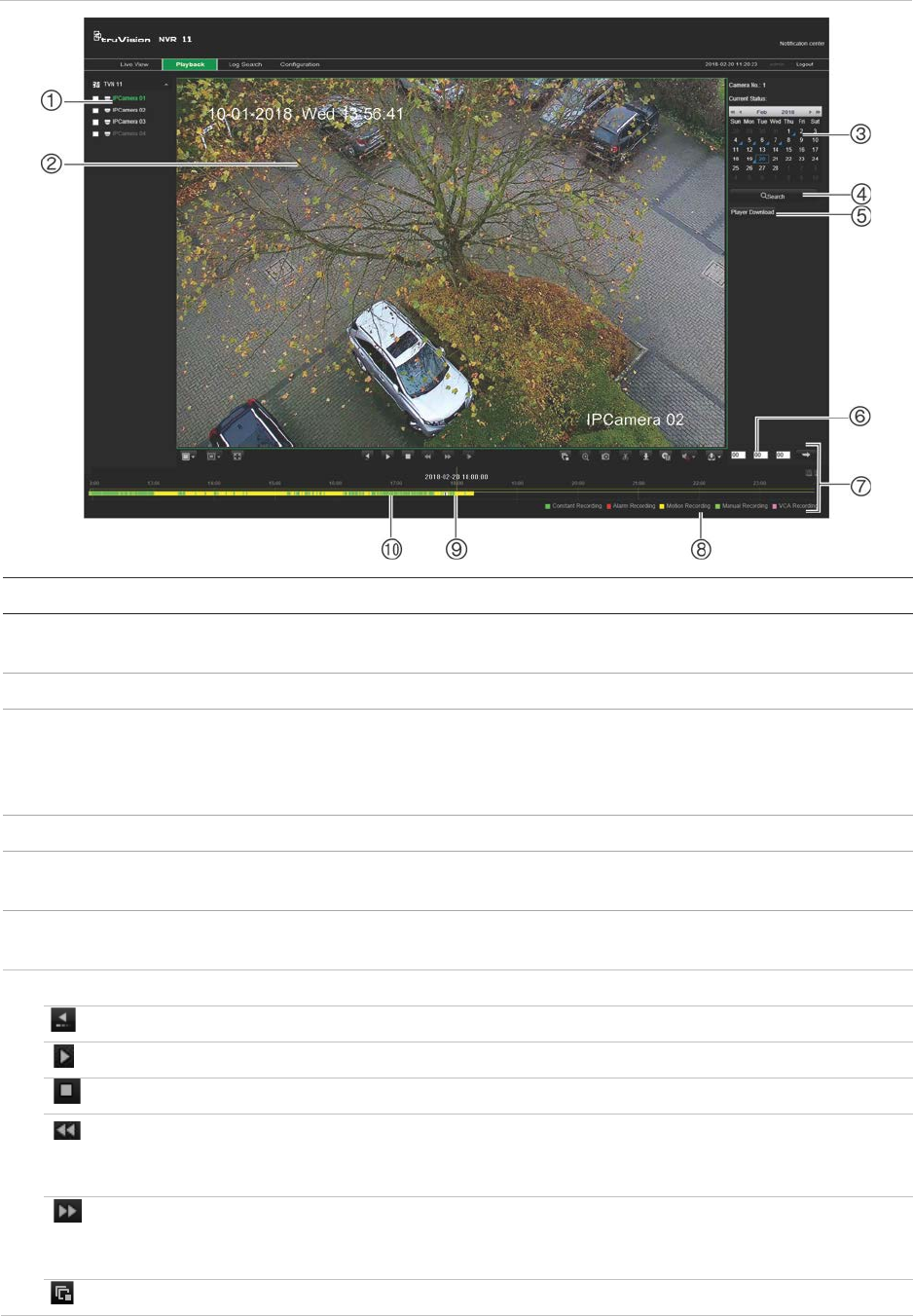
Chapter 18: Using the web browser
TruVision NVR 11 User Manual 147
Figure 35: Browser playback page
Description
1
. Camera panel. Select the cameras for playback. Move the mouse over the area to display the list
of cameras available. Use the slide bar to see more cameras.
2
. Playback viewer.
3
. Calendar panel.
Blue: Current selected date
Green: Current date
Blue triangle in the corner of a day: Recordings available for this day
4
. Search: Click to start searching recorded files for the selected camera.
5
. Player Download button. Click to download TruVision Player on to your PC to play back
recordings.
6
. Time field. Enter the time from which to start playback of the recordings for all the selected
cameras.
7
. Playback control toolbar:
Reverse: Click to reverse playback.
Start/stop: Start or stop playback.
Stop playback. Timeline jumps back to 00:00:00 time (midnight) of the previous day.
Speed down: Click to scroll through the different speeds available: single frame, 1/8
speed, ¼ speed, ½ speed, normal, X2 speed, X4 speed, X8 speed, maximum speed.
Current speed is displayed under the camera name on top right of window.
Speed up: Click to scroll through the different speeds available: single frame, 1/8 speed, ¼
speed, ½ speed, normal, X2 speed, X4 speed, X8 speed, maximum speed. Current speed
is displayed under the camera name on top right of window.
Single frame: Click to play back one frame at a time.
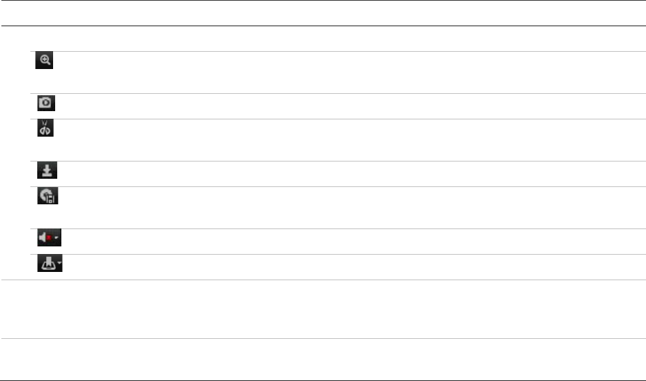
Chapter 18: Using the web browser
148 TruVision NVR 11 User Manual
Description
8
. Audio and video control toolbar:
Digital Zoom
.
Access digital zoom. See “Digital zoom in playback” on page 53 for further
information.
Snapshot: Capture a snapshot of the video.
Video clips: Start/stop video clip during playback. Sections of a recording can be saved to
an external storage device.
Download: Download video clips.
Backup: Click to make back up of recorded files to save locally on the recorder. A list of
the recorded files appears
Audio: Click to enable/disable audio.
Bookmark management: Manage bookmarks.
9
. Recording type: Description of the color coding of recording types that appear in the playback
progress bar. Green indicates constant recording. Red indicates alarm recording. Yellow indicates
motion recording. Pale green indicates manual recording. Magenta indicates VCA recording.
10
. Recording progress bar: This bar displays how much of the period has been recorded. It
indicates in color the type of recording.
Select a camera and a day to search from on the calendar displayed, and then click
Search. The timeline below the page indicates video recorded for the specified day.
The timeline also classifies by color the type of recording with each type.
Click and drag the marker across the timeline on where you want video playback to
begin, and then click Play on the playback control toolbar. You can capture a snapshot
of a video image, save the video playback, or download the recorded video.
Search for event logs
The recorder compiles a log of events, such as the start or end of video recording,
recorder notifications, and alarms, through which you can easily search. Logs are
categorized by the following types:
• Alarm: Includes motion detection, tamper detection, video tampering, and other
alarm events
• Notifications: Includes system notifications such as video loss, HDD failures, and
other system-related events
• Operations: Includes users access to the web interfaces and other operational
events
• Information: Includes general information on the recorder actions, such as the start
and end of video recording, etc.
To search for logs, click Log on the menu bar, select a log type, specify a date and time
range, and then click Search. See Figure 36 on page 149 for an example of the results
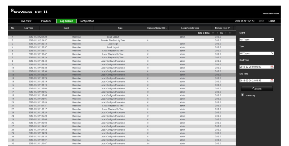
Chapter 18: Using the web browser
TruVision NVR 11 User Manual 149
of a log search. For further information on searching and viewing logs, go to “Search
the system log” on page 138.
Figure 36: Results of a log search
Configure the recorder via the browser
Click Configuration on the menu toolbar to display the configuration window. There
are two ways to configure the recorder: Local and Remote.
Camera management
Camera configuration lets you define communication and network parameters such as
protocol type, maximum file size, stream type and network transmission settings. You
can also specify the directory locations for saving recorded and playback video,
captured images, and downloaded files.
Remote configuration
See Figure 37 on page 150 for an example of the Configuration screen. See Table 17
on page 150 for an overview of the different browser menu functions. Please refer to
the specific sections on the OSD menu functions in the manual for more information on
configuring these functions.
Go to Browser Configuration to set up the browser parameters. See “Access the web
browser” on page 142 for further information.
Note: The configuration settings defined remotely are different from those that can be
defined locally.
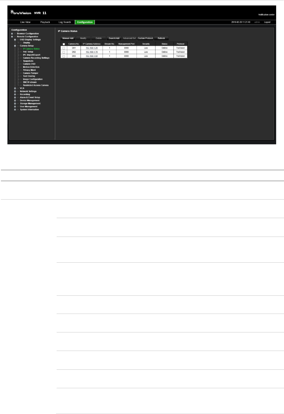
Chapter 18: Using the web browser
150 TruVision NVR 11 User Manual
Figure 37: Remote browser configuration window (Camera Setup > IP Camera Status window
shown)
Table 17: Description of the Remote configuration windows
Menu Function Description
OSD Display
Settings Display Define the resolution of the monitor.
Camera Setup IP Camera Status Search and add IP cameras. See “IP camera status” on
page 66 for further information
PoE Setup Track the PoE power consumption. See “PoE setup” on
page 70 for further information.
IPC Import/Export Import and export the IP camera configuration information.
See “Importing/exporting IP camera files” on page 70 for
further information.
Camera Recording
Settings Define the general camera settings such as camera name,
stream record mode, resolution, frame rate, stream type,
video encoding, and pre and post event times. See “Camera
OSD” on page 74 for more information.
Snapshots Define the image quality and resolution of snapshots. See
“Snapshots” on page 74 for further information.
Camera OSD Define which information is displayed on-screen. See
“Camera OSD” on page 74 for further information.
Motion Detection Define motion detection parameters. See “Motion detection”
on page 76 for more information.
Privacy Mask Define the on-screen privacy mask areas. See “Privacy
mask” on page 78 for more information.
Camera Tamper Define the video tampering detection settings. See “Camera
tamper” on page 79 for more information.
Text Overlay Define the text to be added on-screen to display extra
information, such as contact information. This text is
embedded in the video and cannot be removed.

Chapter 18: Using the web browser
TruVision NVR 11 User Manual 151
Menu Function Description
This can only be defined via the browser.
Image Configuration Define the brightness, contrast, saturation, and hue values
of the image. See “Image settings” on page 75 for more
information.
BNC/V-stream Define the V-stream parameters. See “V-stream encoding”
on page 87 for more information.
Restricted Access
Camera Define which cameras can be seen on the monitor. See
“Restricted access camera” on page 79 for more
information.
VCA VCA Define an area on screen to enable a VCA alarm from IP
cameras. See “VCA setup” on page 80” for further
information.
Network Settings Network Settings Define the general network settings. See “Network settings”
on page 88 for more information.
PPPoE Define the PPPoE settings. See “PPPoE settings” on page
90 for more information.
DDNS Define the DDNS settings. See “DDNS settings” on page 91
for more information.
NTP Define the NTP server settings. See “NTP server settings”
on page 92 for more information.
Email Define the settings to send an email. See “Email settings”
on page 92 for more information.
FTP Define the FTP settings. See “Configure an FTP server to
store snapshots” on page 93 for more information.
SNMP Define the SNMP settings. See “SNMP settings” on page 94
for more information.
Network Storage Define the type and location of the network storage system.
See “Add a HDD” on page 127 for further information.
UPnP Enable this function so that the recorder can automatically
configure its own port forwarding. See “UPnP settings” on
page 94 for more information.
HTTPS Define self-signed server certificates as well as request
certified server certificates to ensure your network security.
See “HTTPS settings” on page 142 for further information.
Network Statistics Check the bandwidth being used by remote live view and
playback. See “Network statistics” on page 97 for more
information.
IP Address Filter Define the list of forbidden or allowed IP addresses that can
be accessed by the recorder. See “Filter IP addresses” on
page 97 for more information.
Recording Recording Schedule Define the recording schedules. See “Recording schedule”
on page 99 for more information.
Manual Recording Define which cameras can manually record. See “Manual
recording” on page 103 for more information.

Chapter 18: Using the web browser
152 TruVision NVR 11 User Manual
Menu Function Description
Alarm & Event
Setup Alarm Input Define the alarm input parameters for when an external
alarm is triggered. See “Set up alarm inputs” on page 104 for
more information.
Alarm Output Define the response when an external alarm is triggered.
See “Manual trigger” on page 107 for more information.
Manual Trigger Define the manually trigger outputs of the recorder. See
“Manual trigger” on page 107 for further information.
Buzzer Settings Define the warning buzzer time. See “Buzzer” on page 107
for more information.
Notifications Define the notification parameters when irregular events
occur, such as a HDD is full. See “Event notification” on
page 107 for more information.
Video Loss Define the video loss detection settings. See “Video loss” on
page 110 for more information.
Alarm Host Setup Define the remote alarm host. See “Alarm host setup” on
page 110 for more information.
Intrusion Zone
Setup Define the alarm panel in the recorder. See “Intrusion
integration alarm reporting” on page 111 for more
information.
Intrusion Panel
Setup Define the zones in an alarm panel. See “Intrusion
integration alarm reporting” on page 111 for more
information.
Device
Management Time & Date Setting Define time and date. See “Time and date” on page 119 for
more information.
General Settings Define the general settings of the recorder such as
language, device name, enable the wizard, menu timeout,
and enable front panel lock. See “General recorder settings”
on page 121 for more information.
Configuration Files Import/export configuration settings, restore default factory
settings, and restart the recorder. See “Configuration files”
on page 122 for more information.
Upgrade Firmware Upgrade the recorder firmware. See “Upgrade system
firmware” on page 123 for more information.
Holiday Define how recordings occur during holiday periods. See
“Holiday schedules” on page 124 for more information.
System Service Enable/disable the RTSP protocol. See “System service” on
page 124 for more information.
Storage
Management HDD Information Define the HDD basic settings and initialize the HDD. See
“HDD status information” on page 126 and “Initialize a HDD”
on page 126 for more information.
Storage Mode Define the storage mode of the HDD. See “Storage mode”
on page 127 and “Error! Reference source not found.”
Error! Bookmark not defined. for more information.
S.M.A.R.T. Settings List the S.M.A.R.T. information on the HDD. See
“S.M.A.R.T. settings” on page 128 for more information.
User Management Users Define, modify, and delete users. See Chapter 16 “User
management” on page 131 for more information.

: Using the web browser
TruVision NVR 11 User Manual 153
Menu Function Description
System
Information Device Info Review the status of the device. See Chapter 17
“information” on page 135 for more information.
Camera Review the status of the cameras. See Chapter 17 “System
information” on page 135 for more information.
Record Review the status of the recordings. See Chapter 17
“System information” on page 135 for more information.
Alarm Input Review the status of the alarm inputs. See Chapter 17
“System information” on page 135 for more information.
Alarm Output Review the status of the alarm outputs. See Chapter 17
“System information” on page 135 for more information.
Network Review the status of the network. See Chapter 17 “System
information” on page 135 for more information.
HDD Review the status of the HDD.

154 TruVision NVR 11 User Manual
Appendix A
Specifications
TVN 1104c(S) TVN 1108(S) TVN 1116(S)
Video
& audio input
Video compression
H.264 and H.265
V
ideo input 4-ch 8-ch 16-ch
IP video input
Up to 4-ch Up to 8-ch Up to 16-ch
Audio compression
G711U,G711A,G722,G726,MPEG2,AAC
Audio input
1-ch, RCA (2.0 Vp-p, 1 kΩ)
Video & a
udio output
HDMI
/VGA output VGA: 1-
ch, 1920 × 1080/60Hz, 1280 × 1024/60Hz, 1280 × 720/60Hz, 1024 ×
768/60 Hz
HDMI: 1-ch, 1920 × 1080/60Hz, 1280 × 1024/60Hz, 1280 × 720/60Hz, 1024
× 768/60 Hz
Encoding resolution
5MP@12 fps / 3MP@15 fps / 1080p / 720p / WD1 / 4CIF / VGA/CIF
Frame rate
Main stream: 25 fps (PAL) / 30 fps (NTSC)
Substream: WD1/4 CIF@12 fps (non-real time); CIF / QVGA / QCIF (real
time)
Video bit rate
32 Kbps to 10 Mbps
Audio output
1-ch, RCA (Linear, 1 KΩ)
Audio bit rate
64 Kbps
Stream type
Video, Video & Audio
Synchronous playback
4-ch 8-ch 16-ch
Network management
Network protocols
TCP/IP, PPPoE, DHCP, DNS, DDNS, NTP, SADP, NFS, iSCSI, UPnP™,
HTTPS, ONVIF
Hard disk
SATA
1 SATA interface 2 SATA interfaces
Capacity
Up to 6TB capacity

Appendix A: Specifications
TruVision NVR 11 User Manual 155
TVN 1104c(S) TVN 1108(S) TVN 1116(S)
External interface
Bi
-directional audio input 1-ch, RCA (2.0 Vp-p, 1 KΩ) (using the audio input)
Network interface
1 RJ45 10M / 100M
self-adaptive Ethernet
interface
1 RJ45 10M / 100M / 1000M self-adaptive
Ethernet
interface
USB interface
Front panel: USB 2.0; Back panel: USB 2.0
Alarm in/out
4/1 4/1 4/1
Miscellaneous
Power supply
TVN 1104c (EMEA
only): 12 VDC TVN 1108 (EMEA only):
12 VDC TVN 1116 (EMEA only):
12 VDC
TVN 1104cS: 48 VDC TVN 1108S: 110 to
240 V, 6.3 A, 50 to 60
Hz
TVN 1116S: 110 to
240 V, 6.3 A, 50 to 60
Hz
Power consumption
(without HDD)
≤ 50 W ≤ 120 W ≤ 200 W
Operating temperature
-10 to +55 ºC (14 to 131 °F)
Relative humidity
10 to 90%
Dimensions (W x H x D)
315 × 242 × 45 mm
(12.4 × 9.5 × 1.8 in.) 380 × 320 × 48 mm (15.0 × 12.6 × 1.9 in.)
Weight
TVN-1104c (EMEA
only): 1 kg TVN-1108 (EMEA only)
:
2 kg TVN-1116 (EMEA only):
2 kg
TVN-1104cS: 1.3 kg TVN-1108S: 2.4 kg TVN-1116S: 2.5 kg

156 TruVision NVR 11 User Manual
Appendix B
Port forwarding information
A router is a device that lets you share your internet connection between multiple
computers. Most routers will not allow incoming traffic to the device unless you have
configured them to forward the necessary ports to that device. By default our software
and recorders require the following ports to be forwarded:
Note: Port forwarding may reduce the security of the computers on your network.
Please contact your network administrator or a qualified network technician for further
information.
Port: 80
HTTP protocol Used to connect via IE browser.
Port: 8000
Client Software Port Used to connect to video streams.
Port: 554
RTSP Port Real time streaming protocol.
Used to record video remotely.
Port: 1024
RTSP Port for 3G/4G Use with mobile apps.
Used for 3G/4G connection.
Note: It is recommended that the RTSP port 1024 should only be used when
experiencing connection issues over a 3G/4G connection.
Seeking further assistance
Third-party assistance on configuring popular routers can be found at:
http://www.portforward.com/
http://canyouseeme.org/
http://yougetsignal.com
Note: These links are not affiliated with nor supported by Interlogix technical support.
Many router manufacturers also offer guides on their websites as well as including
documentation with the product.
On most routers the brand and model number is located on or near the serial number
sticker on the bottom of the device.
Appendix B: Port forwarding information
TruVision NVR 11 User Manual 157
If you cannot find any information for your particular router, please contact your router
manufacturer or internet service provider for further assistance.
158 TruVision NVR 11 User Manual
Index
A
Alarm inputs
set up, 104
Alarm notifications
external alarms, 104
response actions, 105
video loss, 110
video tamper, 79
warning buzzer, 107
Alarm outputs
manual acknowledment, 107
set up, 106
Archive
bookmarked recordings, 55
bookmarks, 59
export files to a backup device, 57
locked files, 55, 59
quick archive, 56
search results, 57
video clips, 55, 59
B
Back panel description, 9
Bad sector detection, 129
Bookmarks
archive, 59
create, 54
delete, 54
saving, 54
search, 38
types, 54
C
Cameras
image settings, 75
layout, 64
pre and post event times, 72
privacy mask, 78
recording settings, 72
supported, 66
Configuration settngs
export, 122
import, 122
D
Daily schedules
recording, 101
Date format, 119
DDNS settings, 91
Default settings
restore, 123
Digital zoom
description, 33
playback, 53
web browser, 148
Display settings, 75
DST, 119
Dual stream recording
setup, 72
Dwell time, 62
E
Email
encryption, 92
notification set up, 92
Event logs
search remotely, 148
Event notifications
types, 107
Export snapshots
TruVision Navigator, 60
Export video
TruVision Navigator, 60
F
Factory default settings
restore, 123
Firmware
update, 123
Frame-by-frame playback, 51
Front panel
button functions by task, 19, 20
Front panel description, 19
Front panel lock, 121, 122
FTP server settings, 93
TruVision NVR 11 User Manual 159
H
HDD
add, 127
check status, 126
initialize, 126
overwrite, 127
properties, 128
storage mode, 127
Holiday schedules
record, 124
HTTP
enable protocol, 124
I
Instant playback, 41
Instant playback duration, 102
Intrusion integration alarm reporting
setup, 111
Intrusion panel setup, 111
IP addresses
forbidden/allowed, 97
IP cameras
add to recorder, 67
import/export configuration files, 70
LAN network, 68
passwords, 67
PoE ports, 68
PoE power budget information, 70
status, 66
IR remote control
change ID, 121
description, 22
ISAPI
enable protocol, 124
L
Language
change GUI language, 121
Live view
digital zoom, 33
presets and preset tours, 34
shadow tours, 34
toolbar, 31
web browser, 143
Local audio output, 62
Lock/unlock recorded files, 54
Locked files
archive, 59
M
Main menu
description, 24
Main stream recording
setup, 72
Manual recording, 103
Menu timeout
change, 121
Monitor time bar
display, 62
Monitors
change output mode, 121
connect, 12
resolution, 62
select main/event, 62
video outputs, 29
Motion detection
playback, 47
setup, 76
smart playback, 48
Mouse pointer speed
change, 121
Mouse pop-up menu, 29
Multiview layout, 62
N
Network packet data
export, 96
Network settings
general set up, 88
Network status, 95
Network traffic
check, 95
NTP server, 92
O
OSD settings, 74
P
Password
activate admin, 15
change admin password, 134
change user password, 134
enable/disable login password, 121
Password required, 121
Playback
24-hour playback, 45
alarm inputs, 47
arcived files, 52
bookmarked recordings, 38
bookmarks, 46
change playback speed, 51
event recordings, 38
events, 47
import external files, 46
instant playback, 41
motion and VCA events, 48
motion detection, 47
search by time and date, 37
search by video type, 37
search results, 37
skip time, 51
smart events, 48
snapshots, 39, 46
160 TruVision NVR 11 User Manual
split-screen, 50
sub-periods, 50
use the web browser, 146
Playback control panel
description, 43
PoE power budget information, 70
Port forwarding, 98
Power up and down recorder, 14
PPPoE settings, 90
Preset tours, 84
call up, 86
set up, 86
Presets
call up, 86
delete, 84, 86
quick access, 34
select, 84
set up, 85
Privacy mask, 78
PTZ control panel
description, 34
PTZ dome cameras
control remotely, 145
Q
Quick archive, 56
R
Recorder name
change, 121
Recording
audio setup, 72
auto delete, 72
bitrate setup, 72
frame rate, 72
pre/post event times, 72
recording schedules, 99
Recording schedules
daily, 101, 124
define, 99
Remote alarm host settings, 110
Remote control
connect to the recorder, 24
Resolution
supported, 72
Restricted access, 79
RTSP
enable protocol, 124
S
S.M.A.R.T. information, 129
Search
bookmarked recordings, 38
event recordings, 38
logs, 40
recordings, 37
snapshots, 39
system logs, 138
Sequence cameras, 31
Shadow tours
call up, 87
quick access, 34
set up, 87
Skip time
playback, 51
Smart events
playback, 48
Snapshots
capture remotely, 146
setup, 74
TruVision Navigator, 60
upload to FTP server, 93
view, 39, 52
SNMP protocol settings, 94
Soft keyboard, 26
Startup wizard
enable/disable, 121
Startup wizard, 16
Status icons
description, 28
dislpay, 62
Substream recording
setup, 72
System date
display, 119
System information
view, 135
System logs
playback, 138
search, 138
System time
display, 119
T
Time bar
display, 62
Time format, 119
TruVision Player, 56
TVRMobile
push notifications, 115
U
UPnP settings, 94
User privileges
camera configuration, 133
local configuration, 132
remote configuration, 132
Users
add a new user, 131
customize user privileges, 132
delete a user, 133
modify user information, 134
TruVision NVR 11 User Manual 161
V
VCA
setup alarm actions, 80
types, 80
VCA events
playback, 47, 48
Video clips
archive, 59
create, 53
Video format
PAL/NTSC, 14
Video loss
setting up detection, 110
Video outputs, 29
Video search menu, 36
Video tamper
set up to detect, 79
V-stream encoding, 87
4-channel recorder, 87
W
Warning buzzer, 107
Web browser
access, 142
camera management, 149
control PTZ dome camera, 145
digital zoom, 148
live view, 143
network settings, 142
remote configuration, 149
search and play back recorded video, 146
search event logs, 148
video snapshot, 146
