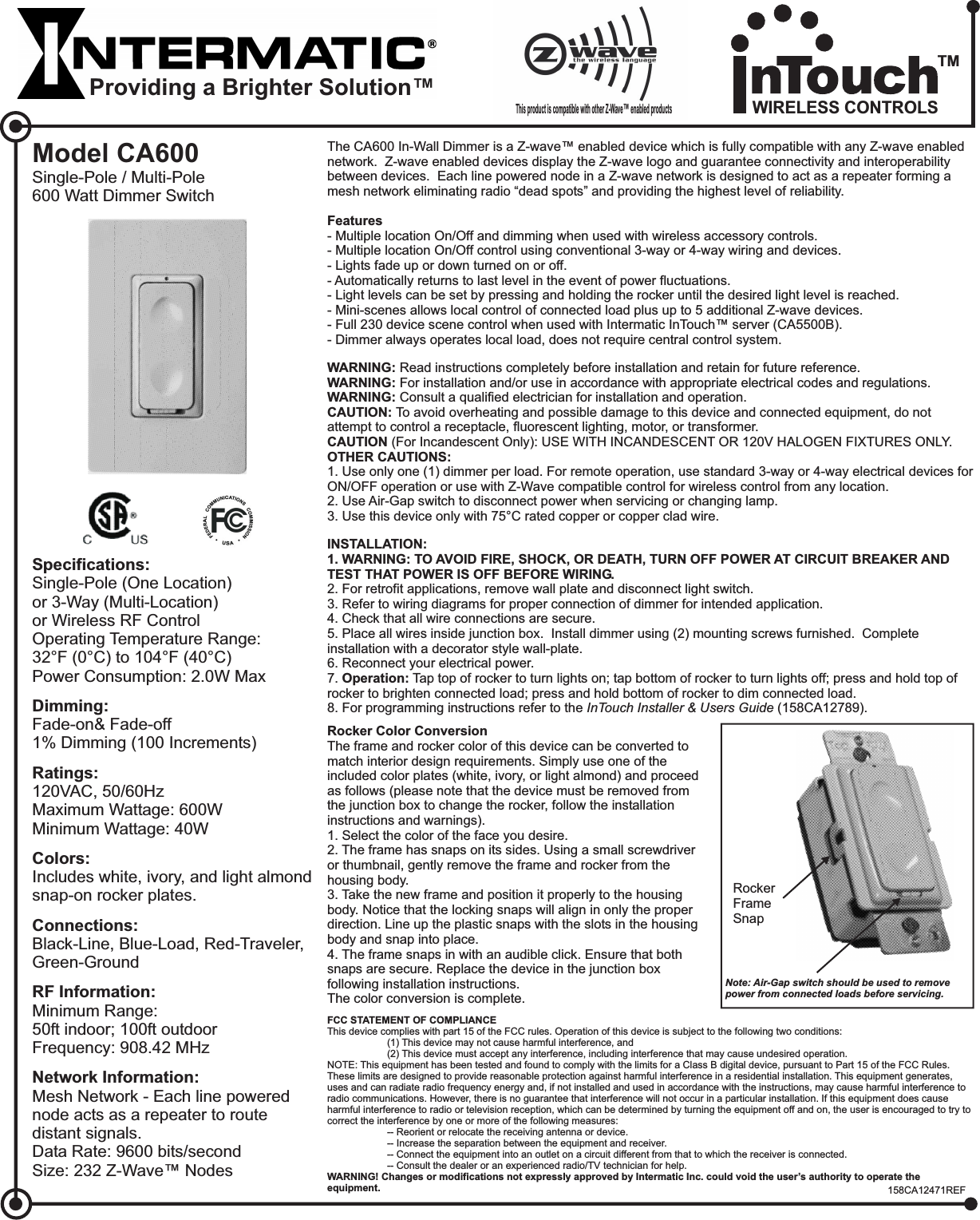
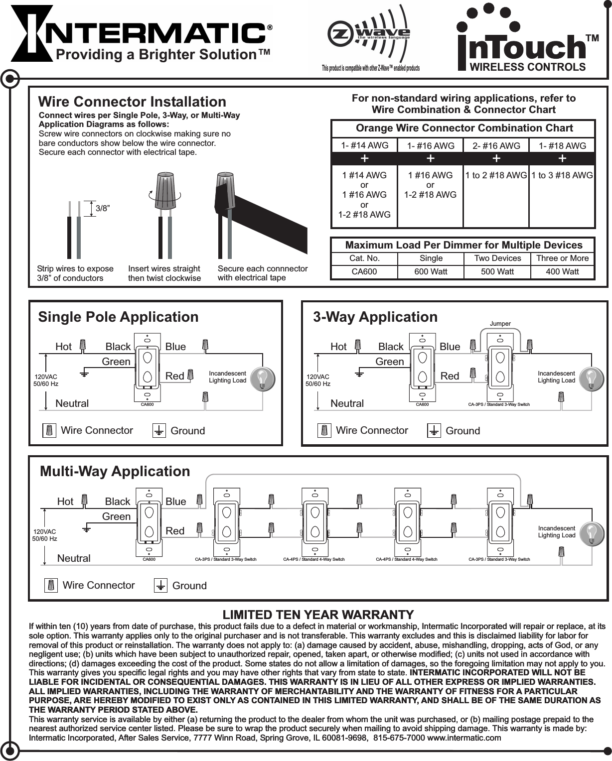
Intermatic CA600 Single-Pole/Multi-Pole 600 Watt Dimmer Switch User Manual CA600

Intermatic Inc Single-Pole/Multi-Pole 600 Watt Dimmer Switch CA600

Exhibit D Users Manual per 2 1033 b3

WARNING: Read instructions completely before installation and retain for future reference.WARNING:WARNING:CAUTION:CAUTIONOTHER CAUTIONS:For installation and/or use in accordance with appropriate electrical codes and regulations.Consult a qualified electrician for installation and operation.To avoid overheating and possible damage to this device and connected equipment, do notattempt to control a receptacle, fluorescent lighting, motor, or transformer.(For Incandescent Only): USE WITH INCANDESCENT OR 120V HALOGEN FIXTURES ONLY.1. Use only one (1) dimmer per load. For remote operation, use standard 3-way or 4-way electrical devices forON/OFF operation or use with Z-Wave compatible control for wireless control from any location.2. Use Air-Gap switch to disconnect power when servicing or changing lamp.3. Use this device only with 75°C rated copper or copper clad wire.Model CA600Single-Pole / Multi-PoleDimmer600 Watt SwitchSpecifications:Ratings:Colors:Connections:RF Information:Network Information:Single-Pole (One Location)or 3-Way (Multi-Location)or Wireless RF Control120VAC, 50/60HzMaximum Wattage: 600WMinimum Wattage: 40WIncludes white, ivory, and light almondsnap-on rocker plates.Black-Line, Blue-Load, Red-Traveler,Green-GroundMinimum Range:50ft indoor; 100ft outdoorFrequency: 908.42 MHzMesh Network - Each line powerednode acts as a repeater to routedistant signals.Data Rate: 9600 bits/secondSize: 232 Z-Wave™ NodesOperating Temperature Range:32°F (0°C) to 104°F (40°C)Power Consumption: 2.0W MaxFade-on& Fade-off1% Dimming (100 Increments)Dimming:INSTALLATION:1. WARNING: TO AVOID FIRE, SHOCK, OR DEATH, TURN OFF POWER AT CIRCUIT BREAKER ANDTEST THAT POWER IS OFF BEFORE WIRING.Operation:2. For retrofit applications, remove wall plate and disconnect light switch.3. Refer to wiring diagrams for proper connection of dimmer for intended application.4. Check that all wire connections are secure.5. Place all wires inside junction box. Install dimmer using (2) mounting screws furnished. Completeinstallation with a decorator style wall-plate.6. Reconnect your electrical power.7. Tap top of rocker to turn lights on; tap bottom of rocker to turn lights off; press and hold top ofrocker to brighten connected load; press and hold bottom of rocker to dim connected load.8. For programming instructions refer to the (158CA12789).InTouch Installer & Users GuideThe CA600 In-Wall Dimmer is a Z-wave™ enabled device which is fully compatible with any Z-wave enablednetwork. Z-wave enabled devices display the Z-wave logo and guarantee connectivity and interoperabilitybetween devices. Each line powered node in a Z-wave network is designed to act as a repeater forming amesh network eliminating radio “dead spots” and providing the highest level of reliability.- Multiple location dimming when used with wireless accessory controls.- Multiple location On/Off control using conventional 3-way or 4-way wiring and devices.- Lights fade up or down turned on or off.- Automatically returns to last level in the event of power fluctuations.- Light levels can be set by pressing and holding the rocker until the desired light level is reached.- Mini-scenes allows local control of connected load plus up to 5 additional Z-wave devices.- Full 230 device scene control when used with Intermatic InTouch™ server .- Dimmer always operates local load, does not require central control system.FeaturesOn/Off and(CA5500B)This product is compatible with other Z-Wave enabled products™Rocker Color ConversionThe frame and rocker color of this device can be converted tomatch interior design requirements. Simply use one of theincluded color plates (white, ivory, or light almond) and proceedas follows (please note that the device must be removed fromthe junction box to change the rocker, follow the installationinstructions and warnings).1. Select the color of the face you desire.2. The frame has snaps on its sides. Using a small screwdriveror thumbnail, gently remove the frame and rocker from thehousing body.3. Take the new frame and position it properly to the housingbody. Notice that the locking snaps will align in only the properdirection. Line up the plastic snaps with the slots in the housingbody and snap into place.4. The frame snaps in with an audible click. Ensure that bothsnaps are secure. Replace the device in the junction boxfollowing installation instructions.The color conversion is complete.RockerFrameSnapFCC STATEMENT OF COMPLIANCEWARNING! Changes or modifications not expressly approved by Intermatic Inc. could void the user’s authority to operate theequipment.This device complies with part 15 of the FCC rules. Operation of this device is subject to the following two conditions:(1) This device may not cause harmful interference, and(2) This device must accept any interference, including interference that may cause undesired operation.NOTE: This equipment has been tested and found to comply with the limits for a Class B digital device, pursuant to Part 15 of the FCC Rules.These limits are designed to provide reasonable protection against harmful interference in a residential installation. This equipment generates,uses and can radiate radio frequency energy and, if not installed and used in accordance with the instructions, may cause harmful interference toradio communications. However, there is no guarantee that interference will not occur in a particular installation. If this equipment does causeharmful interference to radio or television reception, which can be determined by turning the equipment off and on, the user is encouraged to try tocorrect the interference by one or more of the following measures:-- Reorient or relocate the receiving antenna or device.-- Increase the separation between the equipment and receiver.-- Connect the equipment into an outlet on a circuit different from that to which the receiver is connected.-- Consult the dealer or an experienced radio/TV technician for help.Note: Air-Gap switch should be used to removepower from connected loads before servicing.Providing a Brighter Solution™158CA12471REFWIRELESS CONTROLSTM
Single Pole ApplicationHot BlackNeutralBlueIncandescentLighting LoadRedWire Connector GroundGreen120VAC50/60 Hz3-Way ApplicationHot BlackNeutralBlueIncandescentLighting LoadRedWire Connector Ground120VAC50/60 HzJumperCA600 CA600 CA-3PS / Standard 3-Way SwitchMulti-Way ApplicationHot BlackNeutralBlueIncandescentLighting LoadRedWire Connector Ground120VAC50/60 HzCA600 CA-3PS / Standard 3-Way SwitchCA-4PS / Standard 4-Way SwitchCA-3PS / Standard 3-Way Switch CA-4PS / Standard 4-Way SwitchGreenGreenThis product is compatible with other Z-Wave enabled products™LIMITED TEN YEAR WARRANTYIf within ten (10) years from date of purchase, this product fails due to a defect in material or workmanship, Intermatic Incorporated will repair or replace, at itssole option. This warranty applies only to the original purchaser and is not transferable. This warranty excludes and this is disclaimed liability for labor forremoval of this product or reinstallation. The warranty does not apply to: (a) damage caused by accident, abuse, mishandling, dropping, acts of God, or anynegligent use; (b) units which have been subject to unauthorized repair, opened, taken apart, or otherwise modified; (c) units not used in accordance withdirections; (d) damages exceeding the cost of the product. Some states do not allow a limitation of damages, so the foregoing limitation may not apply to you.This warranty gives you specific legal rights and you may have other rights that vary from state to state.This warranty service is available by either (a) returning the product to the dealer from whom the unit was purchased, or (b) mailing postage prepaid to thenearest authorized service center listed. Please be sure to wrap the product securely when mailing to avoid shipping damage. This warranty is made by:Intermatic Incorporated, After Sales Service, 7777 Winn Road, Spring Grove, IL 60081-9698, 815-675-7000 www.intermatic.comINTERMATIC INCORPORATED WILL NOT BELIABLE FOR INCIDENTAL OR CONSEQUENTIAL DAMAGES. THIS WARRANTY IS IN LIEU OF ALL OTHER EXPRESS OR IMPLIED WARRANTIES.ALL IMPLIED WARRANTIES, INCLUDING THE WARRANTY OF MERCHANTABILITY AND THE WARRANTY OF FITNESS FOR A PARTICULARPURPOSE, ARE HEREBY MODIFIED TO EXIST ONLY AS CONTAINED IN THIS LIMITED WARRANTY, AND SHALL BE OF THE SAME DURATION ASTHE WARRANTY PERIOD STATED ABOVE.LIMITED TEN YEAR WARRANTYIf within ten (10) years from date of purchase, this product fails due to a defect in material or workmanship, Intermatic Incorporated will repair or replace, at itssole option. This warranty applies only to the original purchaser and is not transferable. This warranty excludes and this is disclaimed liability for labor forremoval of this product or reinstallation. The warranty does not apply to: (a) damage caused by accident, abuse, mishandling, dropping, acts of God, or anynegligent use; (b) units which have been subject to unauthorized repair, opened, taken apart, or otherwise modified; (c) units not used in accordance withdirections; (d) damages exceeding the cost of the product. Some states do not allow a limitation of damages, so the foregoing limitation may not apply to you.This warranty gives you specific legal rights and you may have other rights that vary from state to state.This warranty service is available by either (a) returning the product to the dealer from whom the unit was purchased, or (b) mailing postage prepaid to thenearest authorized service center listed. Please be sure to wrap the product securely when mailing to avoid shipping damage. This warranty is made by:Intermatic Incorporated, After Sales Service, 7777 Winn Road, Spring Grove, IL 60081-9698, 815-675-7000 www.intermatic.comINTERMATIC INCORPORATED WILL NOT BELIABLE FOR INCIDENTAL OR CONSEQUENTIAL DAMAGES. THIS WARRANTY IS IN LIEU OF ALL OTHER EXPRESS OR IMPLIED WARRANTIES.ALL IMPLIED WARRANTIES, INCLUDING THE WARRANTY OF MERCHANTABILITY AND THE WARRANTY OF FITNESS FOR A PARTICULARPURPOSE, ARE HEREBY MODIFIED TO EXIST ONLY AS CONTAINED IN THIS LIMITED WARRANTY, AND SHALL BE OF THE SAME DURATION ASTHE WARRANTY PERIOD STATED ABOVE.Wire Connector InstallationConnect wires per Single Pole, 3-Way, or Multi-WayApplication Diagrams as follows:Screw wire connectors on clockwise making sure nobare conductors show below the wire connector.Secure each connector with electrical tape.Insert wires straightthen twist clockwiseSecure each connnectorwith electrical tapeMaximum Load Per Dimmer for Multiple DevicesCat. No.CA600Single600 WattTwo Devices500 WattThree or More400 WattFor non-standard wiring applications, refer toWire Combination & Connector ChartOrange Wire Connector Combination Chart1- #14 AWG1 #14 AWGor1 #16 AWGor1-2 #18 AWG+1- #16 AWG1 #16 AWGor1-2 #18 AWG+2- #16 AWG1to2#18AWG+1- #18 AWG1to3#18AWG+Strip wires to expose3/8” of conductors3/8”Providing a Brighter Solution™WIRELESS CONTROLSTM

Navigation menu