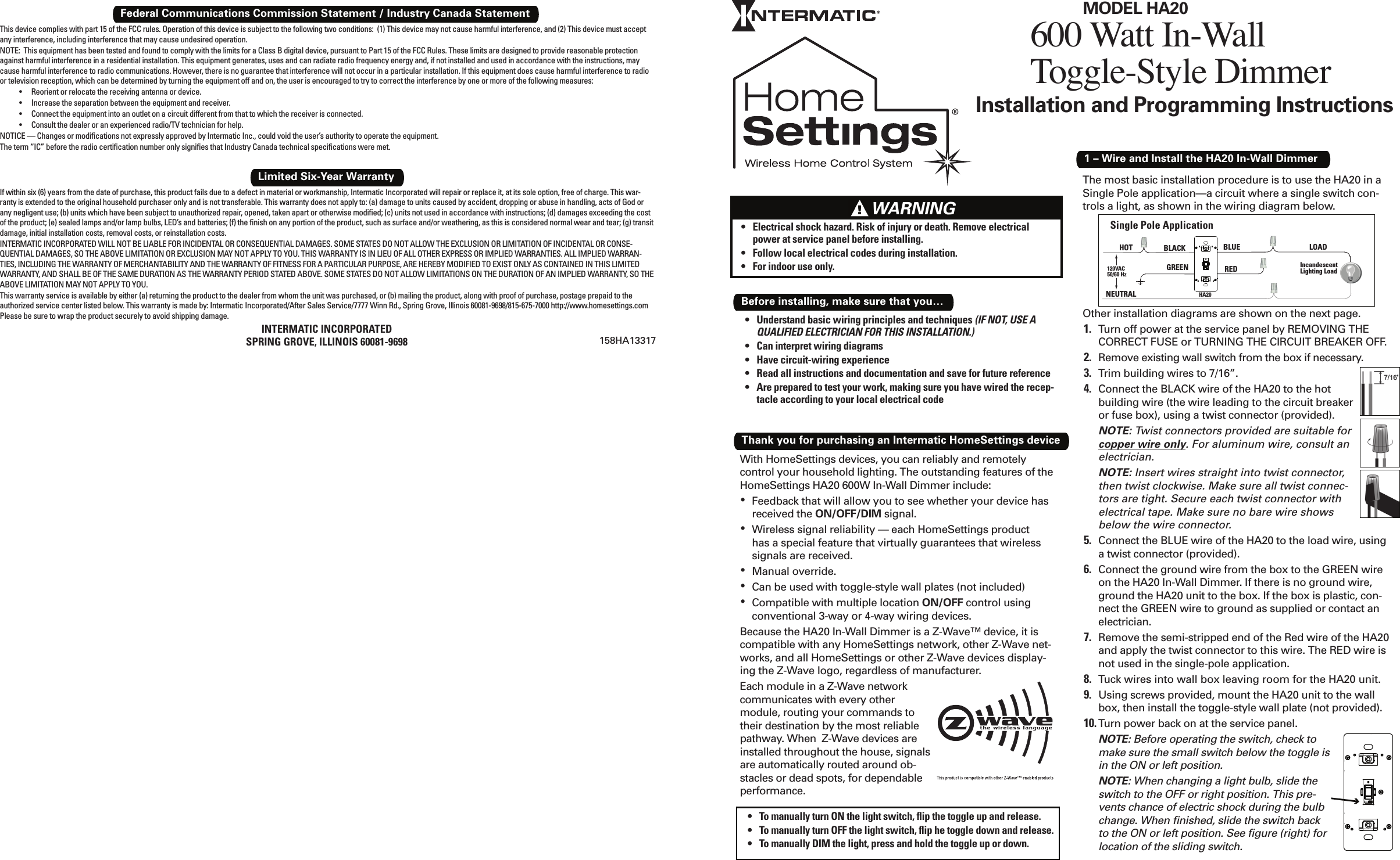
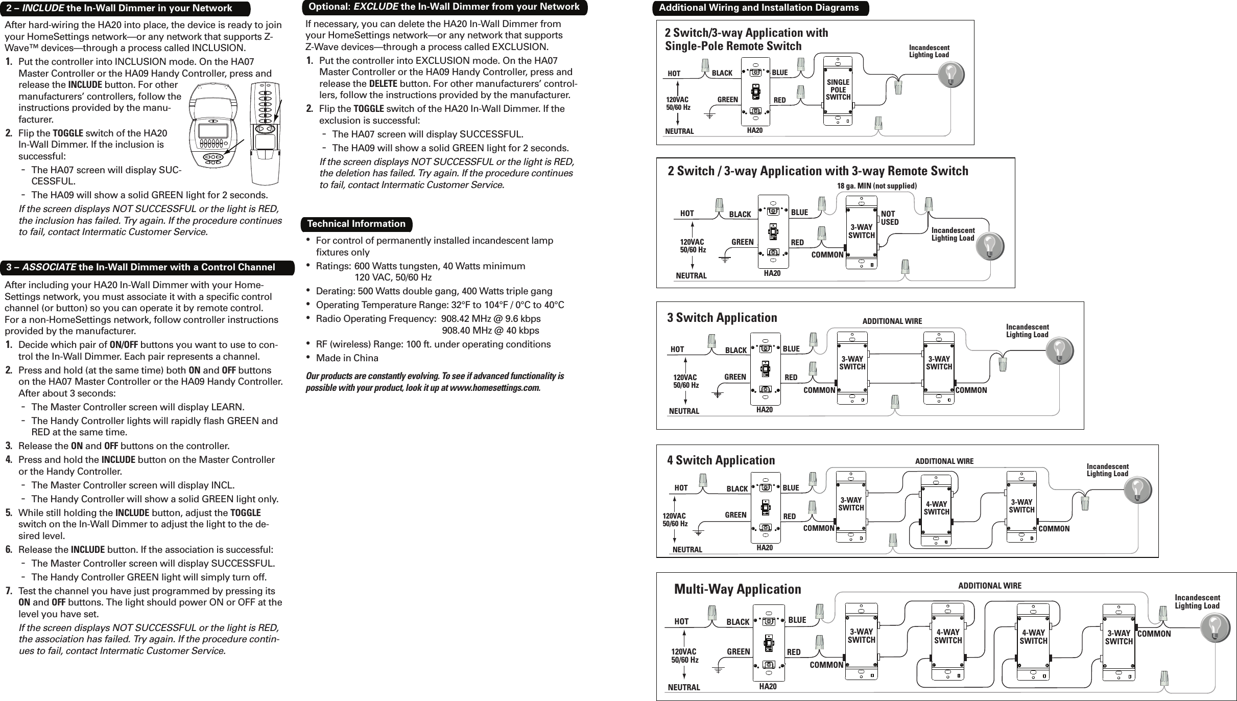
Intermatic HA000020P2 In-Wall Toggle-Style Dimmer Switch User Manual HA20 ENGLISH indd

Intermatic Inc In-Wall Toggle-Style Dimmer Switch HA20 ENGLISH indd

User Manual

1 – Wire and Install the HA20 In-Wall DimmerWith HomeSettings devices, you can reliably and remotely control your household lighting. The outstanding features of the HomeSettings HA20 600W In-Wall Dimmer include:Feedback that will allow you to see whether your device has • received the ON/OFF/DIM signal.Wireless signal reliability — each HomeSettings product • has a special feature that virtually guarantees that wireless signals are received.Manual override.• Can be used with toggle-style wall plates (not included)• Compatible with multiple location •  ON/OFF control using conventional 3-way or 4-way wiring devices.Because the HA20 In-Wall Dimmer is a Z-Wave™ device, it is compatible with any HomeSettings network, other Z-Wave net-works, and all HomeSettings or other Z-Wave devices display-ing the Z-Wave logo, regardless of manufacturer. Each module in a Z-Wave network communicates with every other module, routing your commands to their destination by the most reliable pathway. When  Z-Wave devices are installed throughout the house, signals are automatically routed around ob-stacles or dead spots, for dependable performance.Thank you for purchasing an Intermatic HomeSettings deviceThe most basic installation procedure is to use the HA20 in a Single Pole application—a circuit where a single switch con-trols a light, as shown in the wiring diagram below. Other installation diagrams are shown on the next page.Turn off power at the service panel by REMOVING THE 1. CORRECT FUSE or TURNING THE CIRCUIT BREAKER OFF.Remove existing wall switch from the box if necessary.2. Trim building wires to 7/16”.3. Connect the BLACK wire of the HA20 to the hot 4. building wire (the wire leading to the circuit breaker or fuse box), using a twist connector (provided).NOTE: Twist connectors provided are suitable for copper wire only. For aluminum wire, consult an electrician.NOTE: Insert wires straight into twist connector, then twist clockwise. Make sure all twist connec-tors are tight. Secure each twist connector with electrical tape. Make sure no bare wire shows below the wire connector.Connect the BLUE wire of the HA20 to the load wire, using 5. a twist connector (provided).Connect the ground wire from the box to the GREEN wire 6. on the HA20 In-Wall Dimmer. If there is no ground wire, ground the HA20 unit to the box. If the box is plastic, con-nect the GREEN wire to ground as supplied or contact an electrician.Remove the semi-stripped end of the Red wire of the HA20 7. and apply the twist connector to this wire. The RED wire is not used in the single-pole application.Tuck wires into wall box leaving room for the HA20 unit.8. Using screws provided, mount the HA20 unit to the wall 9. box, then install the toggle-style wall plate (not provided).Turn power back on at the service panel.10. NOTE: Before operating the switch, check to make sure the small switch below the toggle is in the ON or left position. NOTE: When changing a light bulb, slide the switch to the OFF or right position. This pre-vents chance of electric shock during the bulb change. When fi nished, slide the switch back to the ON or left position. See fi gure (right) for location of the sliding switch.Single Pole ApplicationNEUTRALHOT BLACK BLUERED120VAC50/60 HzIncandescentLighting LoadGREENLOADHA20To manually turn ON the light switch, fl ip the toggle up and release.• To manually turn OFF the light switch, fl ip he toggle down and release.• To manually DIM the light, press and hold the toggle up or down.• 600 Watt In-Wall Toggle-Style DimmerMODEL HA20Understand basic wiring principles and techniques•   (IF NOT, USE A QUALIFIED ELECTRICIAN FOR THIS INSTALLATION.)Can interpret wiring diagrams• Have circuit-wiring experience• Read all instructions and documentation and save for future reference• Are prepared to test your work, making sure you have wired the recep-• tacle according to your local electrical codeBefore installing, make sure that you…If within six (6) years from the date of purchase, this product fails due to a defect in material or workmanship, Intermatic Incorporated will repair or replace it, at its sole option, free of charge. This war-ranty is extended to the original household purchaser only and is not transferable. This warranty does not apply to: (a) damage to units caused by accident, dropping or abuse in handling, acts of God or any negligent use; (b) units which have been subject to unauthorized repair, opened, taken apart or otherwise modifi ed; (c) units not used in accordance with instructions; (d) damages exceeding the cost of the product; (e) sealed lamps and/or lamp bulbs, LED’s and batteries; (f) the fi nish on any portion of the product, such as surface and/or weathering, as this is considered normal wear and tear; (g) transit damage, initial installation costs, removal costs, or reinstallation costs.INTERMATIC INCORPORATED WILL NOT BE LIABLE FOR INCIDENTAL OR CONSEQUENTIAL DAMAGES. SOME STATES DO NOT ALLOW THE EXCLUSION OR LIMITATION OF INCIDENTAL OR CONSE-QUENTIAL DAMAGES, SO THE ABOVE LIMITATION OR EXCLUSION MAY NOT APPLY TO YOU. THIS WARRANTY IS IN LIEU OF ALL OTHER EXPRESS OR IMPLIED WARRANTIES. ALL IMPLIED WARRAN-TIES, INCLUDING THE WARRANTY OF MERCHANTABILITY AND THE WARRANTY OF FITNESS FOR A PARTICULAR PURPOSE, ARE HEREBY MODIFIED TO EXIST ONLY AS CONTAINED IN THIS LIMITED WARRANTY, AND SHALL BE OF THE SAME DURATION AS THE WARRANTY PERIOD STATED ABOVE. SOME STATES DO NOT ALLOW LIMITATIONS ON THE DURATION OF AN IMPLIED WARRANTY, SO THE ABOVE LIMITATION MAY NOT APPLY TO YOU.This warranty service is available by either (a) returning the product to the dealer from whom the unit was purchased, or (b) mailing the product, along with proof of purchase, postage prepaid to the authorized service center listed below. This warranty is made by: Intermatic Incorporated/After Sales Service/7777 Winn Rd., Spring Grove, Illinois 60081-9698/815-675-7000 http://www.homesettings.com Please be sure to wrap the product securely to avoid shipping damage.INTERMATIC INCORPORATEDSPRING GROVE, ILLINOIS 60081-9698Limited Six-Year WarrantyFederal Communications Commission Statement / Industry Canada StatementThis device complies with part 15 of the FCC rules. Operation of this device is subject to the following two conditions:  (1) This device may not cause harmful interference, and (2) This device must accept any interference, including interference that may cause undesired operation.NOTE:  This equipment has been tested and found to comply with the limits for a Class B digital device, pursuant to Part 15 of the FCC Rules. These limits are designed to provide reasonable protection against harmful interference in a residential installation. This equipment generates, uses and can radiate radio frequency energy and, if not installed and used in accordance with the instructions, may cause harmful interference to radio communications. However, there is no guarantee that interference will not occur in a particular installation. If this equipment does cause harmful interference to radio or television reception, which can be determined by turning the equipment off and on, the user is encouraged to try to correct the interference by one or more of the following measures:Reorient or relocate the receiving antenna or device.• Increase the separation between the equipment and receiver.• Connect the equipment into an outlet on a circuit different from that to which the receiver is connected.• Consult the dealer or an experienced radio/TV technician for help.• NOTICE — Changes or modifi cations not expressly approved by Intermatic Inc., could void the user’s authority to operate the equipment.The term “IC” before the radio certifi cation number only signifi es that Industry Canada technical specifi cations were met.158HA13317Installation and Programming InstructionsElectrical shock hazard. Risk of injury or death. Remove electrical • power at service panel before installing.Follow local electrical codes during installation.• For indoor use only.•       WARNING
After including your HA20 In-Wall Dimmer with your Home-Settings network, you must associate it with a specifi c control channel (or button) so you can operate it by remote control. For a non-HomeSettings network, follow controller instructions provided by the manufacturer. Decide which pair of 1.  ON/OFF buttons you want to use to con-trol the In-Wall Dimmer. Each pair represents a channel.Press and hold (at the same time) both 2.  ON and OFF buttons on the HA07 Master Controller or the HA09 Handy Controller. After about 3 seconds:The Master Controller screen will display LEARN. -The Handy Controller lights will rapidly fl ash GREEN and  -RED at the same time.Release the 3.  ON and OFF buttons on the controller. Press and hold the 4.  INCLUDE button on the Master Controller or the Handy Controller.The Master Controller screen will display INCL. -The Handy Controller will show a solid GREEN light only. -While still holding the 5.  INCLUDE button, adjust the TOGGLE switch on the In-Wall Dimmer to adjust the light to the de-sired level. Release the 6.  INCLUDE button. If the association is successful:The Master Controller screen will display SUCCESSFUL. -The Handy Controller GREEN light will simply turn off. -Test the channel you have just programmed by pressing its 7. ON and OFF buttons. The light should power ON or OFF at the level you have set.If the screen displays NOT SUCCESSFUL or the light is RED, the association has failed. Try again. If the procedure contin-ues to fail, contact Intermatic Customer Service. 3 – ASSOCIATE the In-Wall Dimmer with a Control ChannelIf necessary, you can delete the HA20 In-Wall Dimmer from your HomeSettings network—or any network that supports Z-Wave devices—through a process called EXCLUSION. Put the controller into EXCLUSION mode. On the HA07 1. Master Controller or the HA09 Handy Controller, press and release the DELETE button. For other manufacturers’ control-lers, follow the instructions provided by the manufacturer.Flip the 2.  TOGGLE switch of the HA20 In-Wall Dimmer. If the exclusion is successful:The HA07 screen will display SUCCESSFUL. -The HA09 will show a solid GREEN light for 2 seconds. -If the screen displays NOT SUCCESSFUL or the light is RED, the deletion has failed. Try again. If the procedure continues to fail, contact Intermatic Customer Service. Optional: EXCLUDE the In-Wall Dimmer from your NetworkAfter hard-wiring the HA20 into place, the device is ready to join your HomeSettings network—or any network that supports Z-Wave™ devices—through a process called INCLUSION.  Put the controller into INCLUSION mode. On the HA07 1. Master Controller or the HA09 Handy Controller, press and release the INCLUDE button. For other manufacturers’ controllers, follow the instructions provided by the manu-facturer.Flip the 2.  TOGGLE switch of the HA20 In-Wall Dimmer. If the inclusion is successful:The HA07 screen will display SUC- -CESSFUL.The HA09 will show a solid GREEN light for 2 seconds. -If the screen displays NOT SUCCESSFUL or the light is RED, the inclusion has failed. Try again. If the procedure continues to fail, contact Intermatic Customer Service. 2 – INCLUDE the In-Wall Dimmer in your NetworkFor control of permanently installed incandescent lamp • fi xtures onlyRatings: 600 Watts tungsten, 40 Watts minimum•    120 VAC, 50/60 HzDerating: 500 Watts double gang, 400 Watts triple gang• Operating Temperature Range: 32°F to 104°F / 0°C to 40°C• Radio Operating Frequency:  908.42 MHz @ 9.6 kbps•                 908.40 MHz @ 40 kbpsRF (wireless) Range: 100 ft. under operating conditions• Made in China• Technical InformationOur products are constantly evolving. To see if advanced functionality is possible with your product, look it up at www.homesettings.com.2 Switch/3-way Application with Single-Pole Remote SwitchNEUTRALHOT BLACK BLUE120VAC50/60 HzSINGLEPOLESWITCHIncandescentLighting LoadREDHA20GREEN3 Switch ApplicationNEUTRALHOT BLACK BLUE120VAC50/60 Hz COMMON3-WAYSWITCHRED3-WAYSWITCHIncandescentLighting LoadADDITIONAL WIRECOMMONHA20GREENMulti-Way ApplicationNEUTRALHOT BLACK BLUE120VAC50/60 Hz3-WAYSWITCHREDIncandescentLighting Load4-WAYSWITCH 4-WAYSWITCH 3-WAYSWITCHCOMMONCOMMONADDITIONAL WIREHA20GREEN2 Switch / 3-way Application with 3-way Remote SwitchNEUTRALHOT BLACK BLUE18 ga. MIN (not supplied)120VAC50/60 Hz3-WAYSWITCH IncandescentLighting LoadREDCOMMONNOT USEDHA20GREEN4 Switch ApplicationNEUTRALHOT BLACK BLUE120VAC50/60 Hz3-WAYSWITCHRED4-WAYSWITCHADDITIONAL WIRE3-WAYSWITCHCOMMON COMMONIncandescentLighting LoadHA20GREENAdditional Wiring and Installation Diagrams

Navigation menu