Intermatic Et1705C Instructions Owner S Manual
346213-Installationsheet 346213-InstallationSheet 346213-InstallationSheet 078275 Batch4 unilog cesco-content
346213-Installation 346213-Installation 346213-Installation 078275 Batch4 unilog cesco-content
352485-Installationsheet 352485-InstallationSheet 352485-InstallationSheet 078275 Batch5 unilog cesco-content
2014-07-06
: Intermatic Intermatic-Et1705C-Instructions-Owner-S-Manual intermatic-et1705c-instructions-owner-s-manual intermatic pdf
Open the PDF directly: View PDF ![]() .
.
Page Count: 4
Electronic 7-Day
Time Switch
Time Switch
• InputVoltage:120/208/240/277VAC,50/60Hz
• PowerConsumption:6.0wattsmax.
• ContactConguration:SPST(ET1705C),DPST(ET1725C),and
SPDT(ET1715C).Seewiringdiagramsonnextpage.
Switch Ratings—ET1705C, ET1725C (per pole)
• 30AInductive/Resistive:24/120/208/240VAC,60Hz
• 20ABallast:120-277VAC,60Hz
• 20AResistive:28VDC
• 5ATungsten:120/240VAC,60Hz
• 1HP:120VAC,60Hz
• 2HP:240VAC,60Hz
Switch Ratings—ET1715C (NO/NC) Normally Open/Normally Closed Contact
• 20A/10AInductive/Resistive:120/208/240VAC,60Hz
• 20A/3ABallast:120-277VAC,60Hz
• 5A:120/240VACTungsten
• 1HP/¼HP:120VAC,60Hz
• 2HP/½HP:240VAC,60Hz
Set Points (Events)—EachloadoutputoftheTimeSwitchcansupportup
to14timedONand14timedOFFeventsperday.
Battery-Powered Clock Operation—2yearsminimum(uses2AAA
industrialgradealkalinebatteries,supplied)
Minimum ON or OFF time—1minute
Maximum ON or OFF time—6days,23hours,59minutes
Shipping Weight—2.5lb.(1.1kg)
Enclosures—Threeenclosureoptionsareavailable.
• ET17x5C–NEMA1indoormetalenclosure
• ET17x5CR–NEMA3Rindoor/outdoorlockablemetalenclosure
• ET17x5CPD82–NEMA3Rindoor/outdoorlockableimpactresis-
tantpolycarbonateenclosurewithclearcover
Knockouts—Combination1/2-3/4inchsize,1onbackandeachside,
2onbottom
Wire Size—AWG#10through#18
Installation and User Instructions
MODEL ET1700 Series
TheIntermaticET1700SeriesElectronic7-DayTimeSwitchauto-
maticallyswitchesloadstoapresetweeklyschedulewithto-the-
minuteaccuracy.
Theindependent7-dayprogrammingprovidescompleteexibility
forapplicationswhereloadswitchingdifferseachdayoftheweek.
UsetheET1700seriesasanON/OFFtimerinapplicationsrequir-
ing7-dayloadcontrolsuchaslighting,airconditioningsystems,
pumps,etc.EachloadoutputoftheTimeSwitchcansupportupto
14timedONand14timedOFFeventsperday.Theprogramcan
beoverriddenbypushingtheON/OFFloadoverridebutton(s).
TheET1700SeriesTimeSwitchisdesignedtodirectlyswitchtung-
stenorballastloadsuptoitsrating,andinductiveorresistiveloads
upto30Aat120,208,240,or277VAC.
Specifications
With Battery
Carryover
Description
WARNING: Disconnect the
power to the Time Switch
and the loads before instal-
lation.
1. Remove the mechanism
from the case by de-
pressing the catch at the
top of the case and pull
ing out, as shown.
CAUTION: Do not
touch circuit board
components since
static discharge could damage the microprocessor.
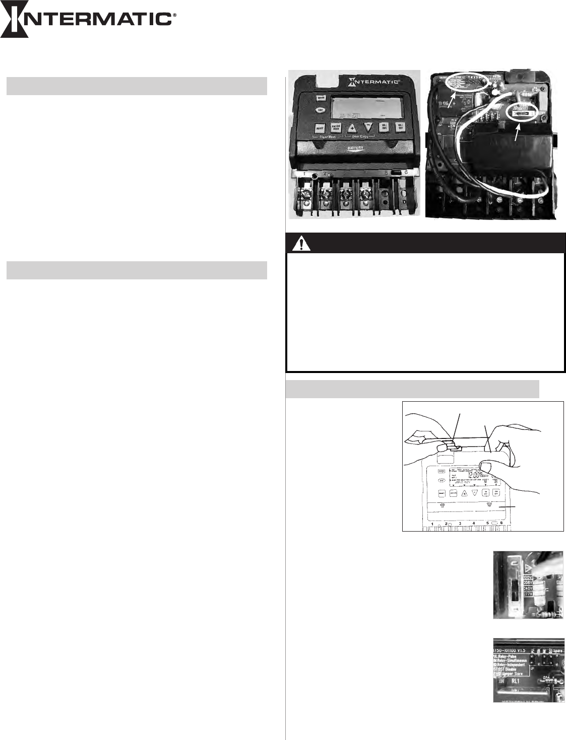
2. Set voltage selector for desired input voltage.
The timer is shipped with voltage set for 120
VAC. To operate at 208, 240 or 277 VAC, move
the selector switch to the desired setting as
marked on the circuit board. See location A in
Rear View above and detail at the right.
3. The timer is shipped with DST (Daylight Saving
Time) enabled. To disable DST, insert a jumper
at location marked DST. See location B in Rear
View above and detail at the right.
4. ET1725C ONLY—Decide whether you want to
control multiple loads simultaneously (SIM),
independently (IND), or with a 2-second pulse
(PUL) (e.g., for use with mechanically held
contactors or bell ringing applications), and make
sure the jumper is positioned accordingly. See location B in Rear
View above and detail at the right. (The unit is shipped with the
loads set for IND.)
Installation Instructions
Slide down
to remove
battery case
Snap out catch
Tilt top forward
Front View Rear View
B
A
• Electrical shock hazard. To avoid fire, shock, or death, disconnect all
power before installing or servicing time switch or connected loads.
• Follow local electrical and safety codes, National Electric Code (NEC)
and Occupational Safety and Health Act Codes (OSHA).
• If the power disconnect point is out of sight, lock it in the OFF position
and tag it to prevent unexpected application of power.
• This time switch must be grounded.
• Do not exceed maximum current carrying capacity.
• Always replace the plastic insulator covering the terminal before
powering ON.
WARNING–Risk of Fire or Electric Shock
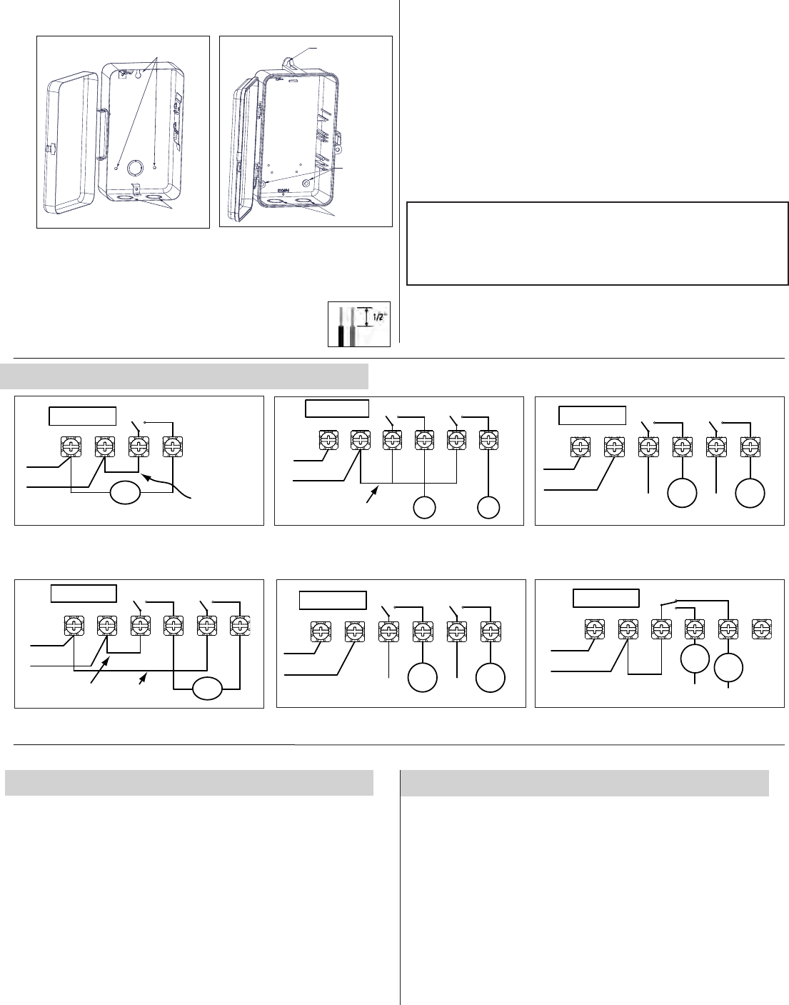
5. Mounttheenclosureinthedesiredlocationusingthe3mountingholes
provided.
Position at eye level if possible, providing space to the left of the
enclosure for the cover to swing open fully, as shown.
6. Replacethemechanismintheenclosure.
7. Lifttheleftsideoftheplasticinsulatorofftheretainingpostandpivotit
upandawaytoexposetheterminalstrip.
8. Stripthesupplyandloadwiresto1/2”.
Use AWG#10-#18 copper conductors only.
Knockouts
Mounting holes
1
Neutral
120VAC
Input
Hot
234
Timer Power
Load
Install jumper
only if timer input
and load voltage
are the same
ET1705 configured for SPST, 120 VAC load
1
Line 2
120/208/240/277
VAC Input
Line 1
23456
Load
1Load
2
Timer Power
ET1715 configured for SPDT load switching
1
Line 2
240VAC Input
Line 1
23456
Line 1
Line 2
Install jumper only if timer input
and load voltage are the same
Timer Power
Load
ET1725 configured for 240VAC DPST load
with jumper set to SIM
1
Line 2
120/208/240/277
VAC Input
Line 1
23456
ON
Install jumper only if timer input
and load voltage are the same OFF
Timer Power
ET1725 configured for pulse SPST load
with jumper set to PUL
1
Line 2
120/208/240/277
VAC Input
Line 1
23456
Load
1
Timer Power
Load
2
ET1725 configured for 2 SPST loads
with jumper set to IND
1
Line 2
120/208/240/277
VAC Input
Line 1
23456
Load
1
Timer Power
Load
2
ET1725 configured for DPST loads
with jumper set to SIM
Mounting
Holes
Knockouts
Mounting
Hole
9. Insertthewireendsundertheproperterminalplates(seewiringdia-
gramselsewhereonthispage)andtightenthescrewsrmly.
10. Connectgroundwiretogroundingterminalatbottomofenclosure.
11. Replacetheplasticinsulatorontheretainingpost.
12. Removethebatterycasebyslidingitdownasshownbythearrows,
theninstall2AAAalkalinebatteries.Makesurethebatteriesarepoint-
inginthedirectionshown.
13. VerifythatthedisplayisONtomakesurethebatteriesareOK.
If the display shows scrambled information, press the RESET button
to clear it up.
14. ApplypowertotheTimeSwitch.
IMPORTANT:PressandholdtheENTERbutton,thenpresstheRESETbut-
ton.Thescreenwillash12:00AMandMON,andtimerstatusisManual
Mode.
NOTE: You must reset the time switch using this procedure whenever you
change the jumpers.
The Time Switch is now ready for programming.
Programming Overview
BypressingtheMODEbutton,theTimeSwitchwillcyclethroughthe
menusnecessaryforprogrammingthecurrenttime,date,andtimed
events.
ThebasicprocedureistousetheMODEbuttontomovefromone
menutothenext(e.g.,DATE,TIME,etc.),the+or– buttonsforthe
rstpartofasetting(e.g.,MONTH),theENTERbuttontomoveto
thenextpartofthesetting(e.g.,YEAR),thenMODEtoexitandmove
tothenextmenu.Toskipamenu,pressMODEtomoveahead.
If you make a mistake, press the MODE button repeatedly to cycle
back around to the error, then make the correct entry.
NOTE: DATE and TIME must be set before you can access any
other programming menus.
1 – Setting Date
1. PresstheMODEbuttonrepeatedlyuntilthewordsSETand
DATEappearintheupperareaofthedisplay.
2. Pressthe+or–buttonstoenterthecurrentMonth.
3. PresstheENTERbuttonwhentheMonthiscorrecttosavethe
setting.ThescreenadvancestocurrentDate.
4. Againpressthe+or– buttonstoenterthecurrentDate,fol-
lowedbytheENTERbutton.
5. RepeattosetthecorrectYear.
6. PresstheMODEbuttontoexitandadvancetosettingthetime.
Wiring Diagrams

2 – Setting Time
1. Ifnecessary,presstheMODEbuttonrepeatedlyuntilthewordsSET
andCLOCKappearintheupperareaofthedisplay.
2. Pressthe+or–buttonstoenterthecurrenttime.
NOTE: To go from AM to PM, keep pressing the + or –
buttons to cycle through the day. You can hold the + or – buttons
down for 3 seconds to make the time scroll quickly.
3. PresstheMODEbuttontoexitandadvancetosettingEvents.
1. Ifnecessary,presstheMODEbuttonrepeatedlyuntilthewordsSET
ON/OFFEVENTSandEVENT01appearonthedisplay.
2. Ifnecessary,presstheENTERbuttontodisplayON@orOFF@
(dependingonwhatyouwanttoset).
3. PresstheDAY buttontodisplay12:00amandalldaysoftheweek.
4. Pressthe+or–buttonstoenterthetimeyouwanttoset.
NOTE: To go from AM to PM, keep pressing the + or – buttons to cycle
through the day. You can hold the + or – buttons down for 3 seconds to
make the time scroll quickly.
5. IfyouwanttheEventtooccurforacombinationofdaysratherthan
everyday(e.g.,weekendsonly,weekdaysonly,orindividualdays),
presstheDAY buttonagainasnecessarytocyclethroughtheindi-
vidualdaysorcombinationofdaysyouwant.
NOTE: To choose a combination not shown during cycling
(e.g., Tuesday and Thursday), you must create an individual event for
each of the days you want.
6. ET1725C ONLY—Foramulti-circuitdevicewithloadsset
independently,youcanchoosetheloadyouwanttheeventtocontrol.
Thedefaultsettingisforbothloads,asyoucanseeonthedisplay.
PresstheON/OFFbuttonunderaloadtoremovetheloadfromthe
event.
7. Whenyouhavesettheeventcorrectly,youhavetwochoices:
- PresstheENTERbuttontosetthenextON/OFFevent(upto28
events).
- PresstheMODEbuttontoexit.
3 – Setting ON/OFF Events
PresstheMODEbuttonrepeatedlytoselectthedesiredoperating
modeonthedisplay.Thereare2options:
• AUTO—wheretheTimeSwitchfollowstheeventsyouhavepro-
grammed,turningthecircuitsONandOFFatthetime(s)set.
NOTE: You can override programmed events and force the
Time Switch ON or OFF by pressing theON/OFF button.
• MANUAL—whereanyeventssetaredisabledandtheTime
SwitchcontrolsallcircuitsthroughtheON/OFFbutton.
NOTE: You can review or edit any programmed events at any time
by pressing the MODE button repeatedly to return to the appropriate
menu, then following programming instruction provided on this sheet.
Operating the Time Switch
Usethisproceduretoclearthesettingsprogrammedforanevent.
1. Ifnecessary,presstheMODEbuttonrepeatedlyuntilthewords
SETON/OFFEVENTSareshownonthedisplay.
2. PresstheENTERbuttonasnecessarytocyclethroughevents
thathavebeensetuntilyouseetheeventyouwanttodelete.
3. Pressthe+or– buttonsATTHESAMETIMEtodisplay--:----.
4. PresstheMODEbuttontoexit.
OPTIONAL – Deleting (Clearing) an Event
LIMITED ONE YEAR WARRANTY
If within the warranty period specified, this product fails due to a defect in material or workmanship, Intermatic Incorporated will repair or replace
it, at its sole option, free of charge. This warranty is extended to the original purchaser only and is not transferable. This warranty does not apply
to: (a) damage to units caused by accident, dropping or abuse in handling, acts of God or any negligent use; (b) units which have been subject to
unauthorized repair, opened, taken apart or otherwise modified; (c) units not used in accordance with instructions; (d) damages exceeding the cost of
the product; (e) sealed lamps and/or lamp bulbs, LED’s and batteries; (f) the finish on any portion of the product, such as surface and/or weathering, as
this is considered normal wear and tear; (g) transit damage, initial installation costs, removal costs, or reinstallation costs.
INTERMATIC INCORPORATED WILL NOT BE LIABLE FOR INCIDENTAL OR CONSEQUENTIAL DAMAGES. SOME STATES DO NOT ALLOW THE
EXCLUSION OR LIMITATION OF INCIDENTAL OR CONSEQUENTIAL DAMAGES, SO THE ABOVE LIMITATION OR EXCLUSION MAY NOT APPLY
TO YOU. THIS WARRANTY IS IN LIEU OF ALL OTHER EXPRESS OR IMPLIED WARRANTIES. ALL IMPLIED WARRANTIES, INCLUDING THE
WARRANTY OF MERCHANTABILITY AND THE WARRANTY OF FITNESS FOR A PARTICULAR PURPOSE, ARE HEREBY MODIFIED TO EXIST ONLY
AS CONTAINED IN THIS LIMITED WARRANTY, AND SHALL BE OF THE SAME DURATION AS THE WARRANTY PERIOD STATED ABOVE. SOME
STATES DO NOT ALLOW LIMITATIONS ON THE DURATION OF AN IMPLIED WARRANTY, SO THE ABOVE LIMITATION MAY NOT APPLY TO YOU.
This warranty service is available by either (a) returning the product to the dealer from whom the unit was purchased, or (b) completing a warranty claim
on line at www.intermatic.com. This warranty is made by: Intermatic Incorporated, Customer Service 7777 Winn Rd. Spring Grove, Illinois 60081-9698.
For warranty service go to: http://www.intermatic.com or call 815-675-7000.
INTERMATIC INCORPORATED
SPRING GROVE, ILLINOIS 60081-9698 158--01102
• BatteriescanbeeasilyreplacedwithoutremovingtheTime
Switchmechanismoreldwiring.
• Pressinanddownward(inthedirectionofthearrows)onthe
batterycover.
• Itisrecommendedtoreplacethebatteriesevery2-3yearswith
2AAAindustrialgradealkalinecellsaspartofnormalmainte-
nanceontheTimeSwitch.
• Besuretoobservebatterypolaritymarkingswheninstalling
batteries.
• Nootherbatterymaintenanceisrequired.
Battery Maintenance
