Intermatic Et8415Cr Instructions Owner S Manual
2014-07-06
: Intermatic Intermatic-Et8415Cr-Instructions-Owner-S-Manual intermatic-et8415cr-instructions-owner-s-manual intermatic pdf
Open the PDF directly: View PDF ![]() .
.
Page Count: 8
Electronic 4 - Circuit Astronomic
7 - Day Time Switch
Installation and Setup Instructions With Supercapacitor Carryover
Federal Communications Commission (FCC) Notice for ET8415 Time Switch
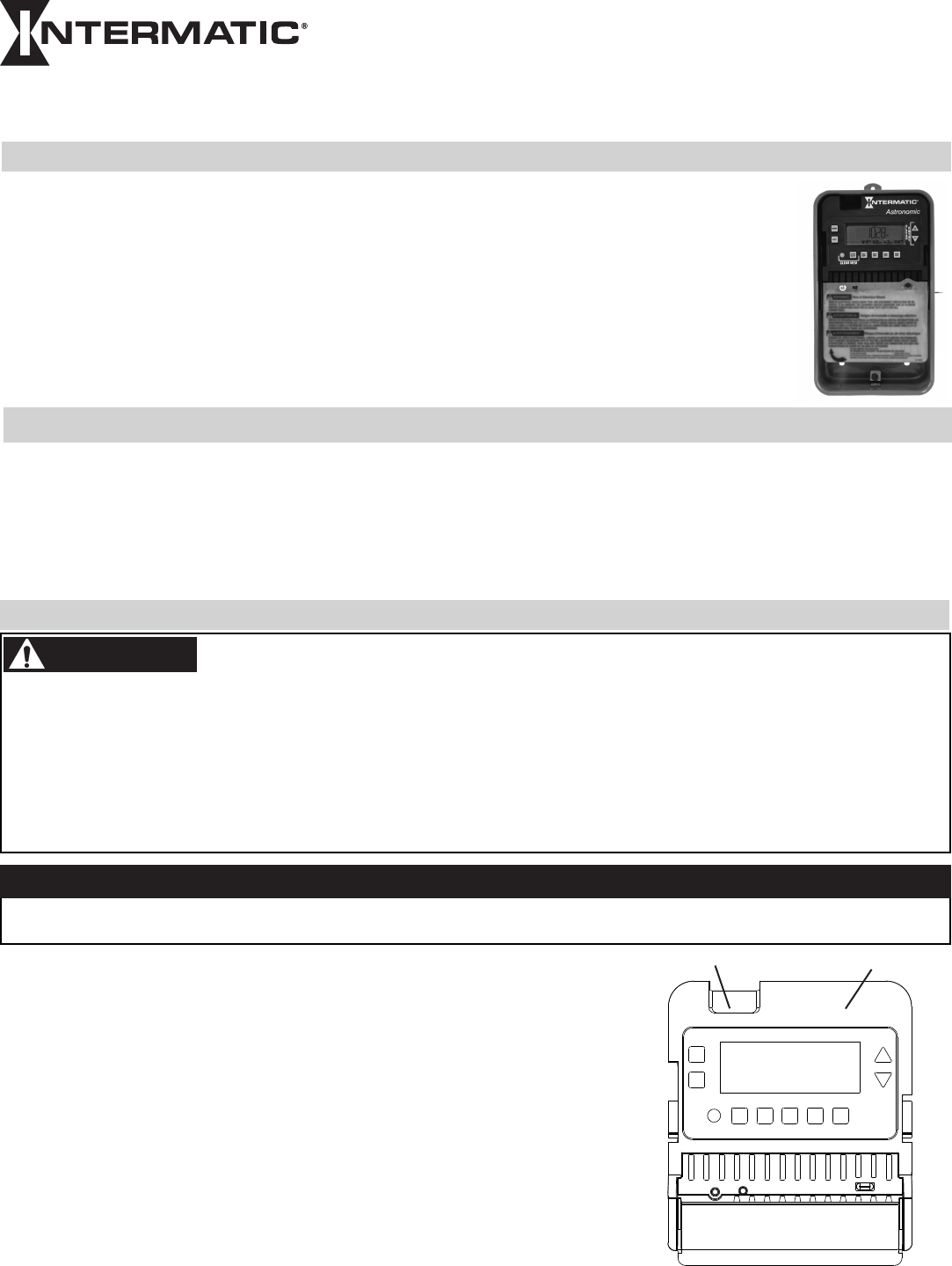
This document explains the setup and conguration of the Intermatic ET8415 4-Circuit Electronic Astronomic
7-Day Time Switch. The ET8415 time switch automatically switches loads to a preset weekly schedule. The time
switch can support up to 28 xed ON and 28 xed OFF events (56 total) and up to four Astro events. Each event
can be applied to any combination of circuits and days.
The time switch features an LCD and panel-mounted control buttons to set, review, and monitor the time switch
functions, including enabling or disabling Daylight Saving Time (DST) and conguring DST switchover dates.
Follow these instructions to complete the installation and programming for the ET8415 time switch.
Description
This device complies with part 15 of the FCC rules. Operation of this device is subject to the following two conditions: (1) This device may
not cause harmful interference, and (2) This device must accept any interference, including interference that may cause undesired opera-
tion. This equipment has been tested and found to comply with the limits for a Class A digital device, pursuant to Part 15 of the FCC Rules.
These limits are designed to provide reasonable protection against harmful interference when the equipment is operated in a commercial
environment. This equipment generates, uses and radiates radio frequency energy and, if not installed and used in accordance with instruc-
tions, may cause harmful interference to radio communications. Operation of this equipment in a residential area is likely to cause harmful
interference that requires the user to correct at his or her own expense.
• Disconnectallpowerbeforeinstallingthetimeswitchorconnectedloads.
• Followlocalelectricalandsafetycodes,NationalElectricCode(NEC)andOccupationalSafetyandHealthActCodes(OSHA).
• Morethanonedisconnectorcircuitbreakermayneedtobeturnedofftode-energizeallconductors.
• Ifthepowerdisconnectpointisoutofsight,lockitintheOFFpositionandtagittopreventunexpectedapplicationofpower.
• Thetimeswitchmustbegrounded.
• Donotexceedmaximumcurrentcarryingcapacity.
• Alwaysreplacetheplasticinsulatortoitsoriginalpositionbeforepoweringthetimeswitch.
• Makesurethereisnowireinsulationundertheterminalplateontimeswitchconnector.Firmlytightenterminalscrews.
Installation
WARNING
MODEL ET8415CR
NOTICE
Follow these instructions to install the time switch.
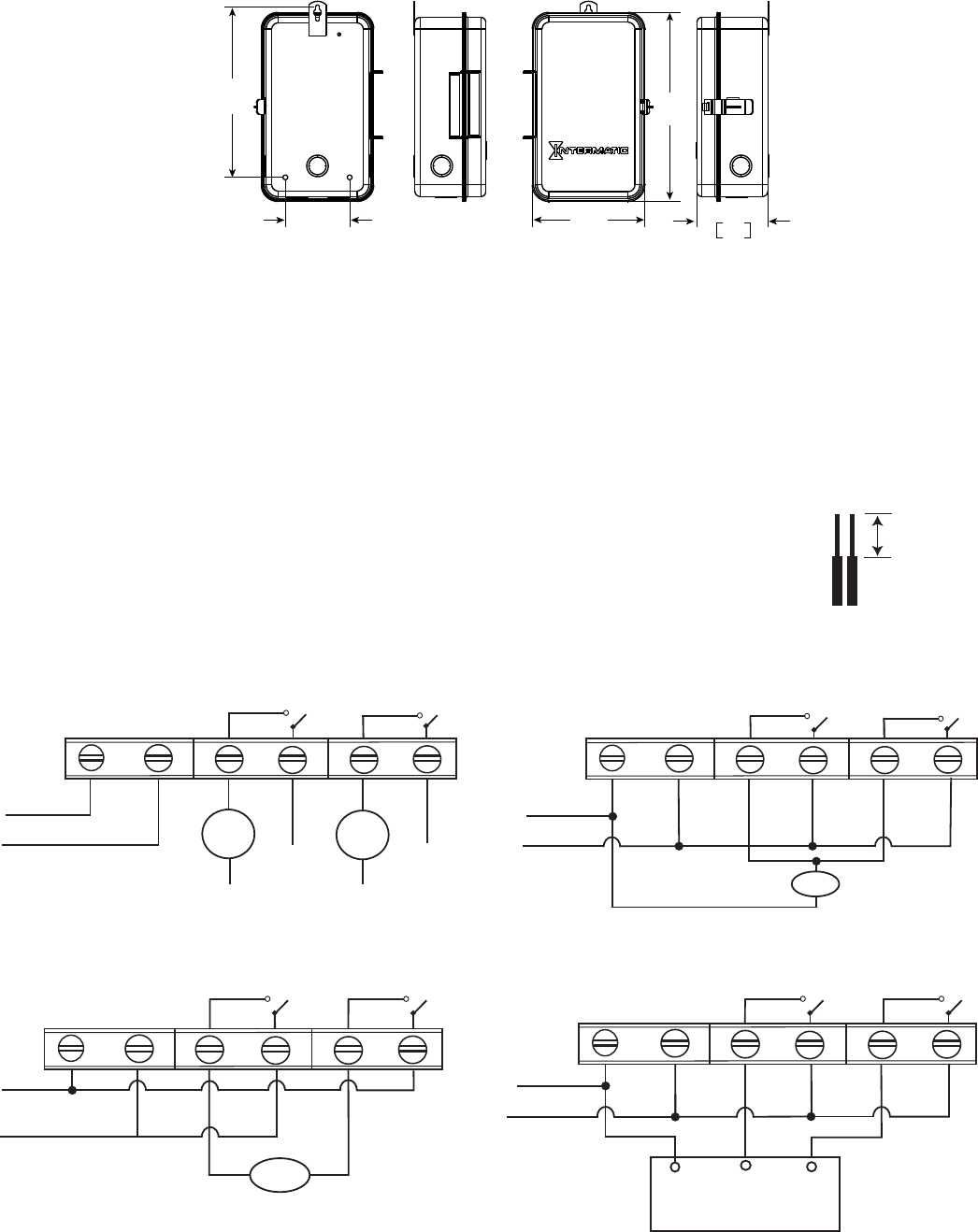
1. Open the time switch enclosure door.
2. Press the catch at the top of the case and pull out the mechanism from the case.
3. Choose a knockout to remove from the enclosure.
NOTE: There are five 1/2 inch to 3/4 inch combination knockouts available. There are
two on the bottom of the enclosure, one on each side, and one on the rear.
4. Insert a athead screwdriver into the slot of a 1/2 inch knockout and punch loose and
remove.
NOTE: If a 3/4 inch knockout is needed, remove the 1/2 inch knockout first, then the
outer ring. Smooth edge if necessary.
Do not touch the circuit board components. Contact with the circuit board components can create static discharge, which can
damage the microprocessor.
Risk of Fire or Electric Shock
Snap out catch Tilt top forward
5. Place the enclosure in the desired location, position at eye level, and provide space for the enclosure door to swing open fully.
6. Drill the holes and then clean out each hole.
7. Insert plastic anchors into the holes, if needed.
IMPORTANT: If you are bringing power wires and wires for connecting applications through the back of the enclosure,
connect the wires before mounting the enclosure. Refer to the wiring diagrams in this manual.
8. Insert the top screw into the top hole and tighten. Hang enclosure.
9. Insert the remaining screws into the other holes and tighten.
10. Replace the time switch in the enclosure.
11. Remove and retain the screw that secures the plastic insulator.
12. Lift the left side of the plastic insulator off the retaining post and pivot it away to expose the terminal strip.
NOTE: Do not remove the insulator.
13. Strip the supply and load wires to 1/2”. Use AWG#10-#18 copper conductors only.
14. Connect the wires to the proper terminals on the time switch connector and tighten the screws firmly.
See wire diagrams.
15. Connect ground wire to grounding terminal at the bottom of the enclosure.
NOTE: Make sure no wire insulation is caught in the terminal.
16. Return the insulator to its original position and replace the screw.
17. Close the enclosure door.
18. Apply power to the time switch.
8.6
[219] 9.6
[243]
3.3
[83] 5.7
[145]
3.6
91
In [mm]
1/2 inch
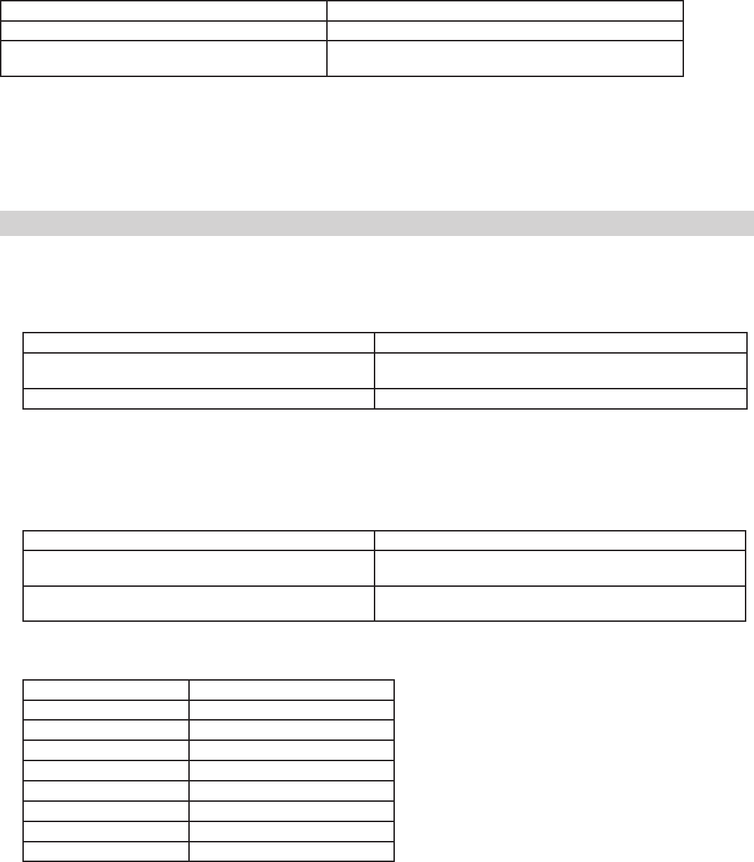
Timer Power
Maintained Contactor
Operation Mode set to PUL.
ET8415 configured for contactor control.
L2/NEUTRAL
L1
Timer Power
Operation Mode set to SIM.
ET8415 configured for 240VAC DPST.
L2
L1
Load
AC IN NO-1 NO-2 COM2
COM1
AC IN
NO-1 NO-2 COM2
COM1
COM
CLOSE
OPEN
Timer Power
Operation Mode set to PUL. ET8415 configured for bell ringing.
L2/Neutral
L1
Load
Timer Power
L2/Neutral
L1
L3
Load
1
Load
2 L5
L4/Neutral L6/Neutral
AC IN
AC IN
NO-1 NO-2 COM2
COM1
Operation Mode set to IND. ET8415 configured for 2 X SPST.
NO-1 NO-2 COM2COM1

The time switch operational modes enable users to control multiple loads simultaneously (SIM), independently (IND), or with a
2-second pulse (PUL). In PUL mode an ON event or manual override causes the rst circuit to turn ON for two seconds, then OFF. An
OFF event or manual override causes the second circuit to turn ON for two seconds, then OFF. Loads 1 and 2 and 3 and 4 can be set to
different operational modes.
NOTE: The operational modes can only be accessed at initial startup of the unit or after the unit memory is cleared.
Follow this procedure to set the operational mode(s).
1. Activate power to the time switch. The screen displays ENTER/NEXT.
2. Press + or - to scroll to the desired operational mode for loads 1 and 2.
3. Press ENTER/NEXT to scroll to the operational mode for loads 3 and 4.
NOTE: Operational Mode is set according to load pair. Set the operational mode for loads 1 and 2 first, then loads 3 and 4.
4. Press ENTER/NEXT to save the setting.
Setting The Operational Mode
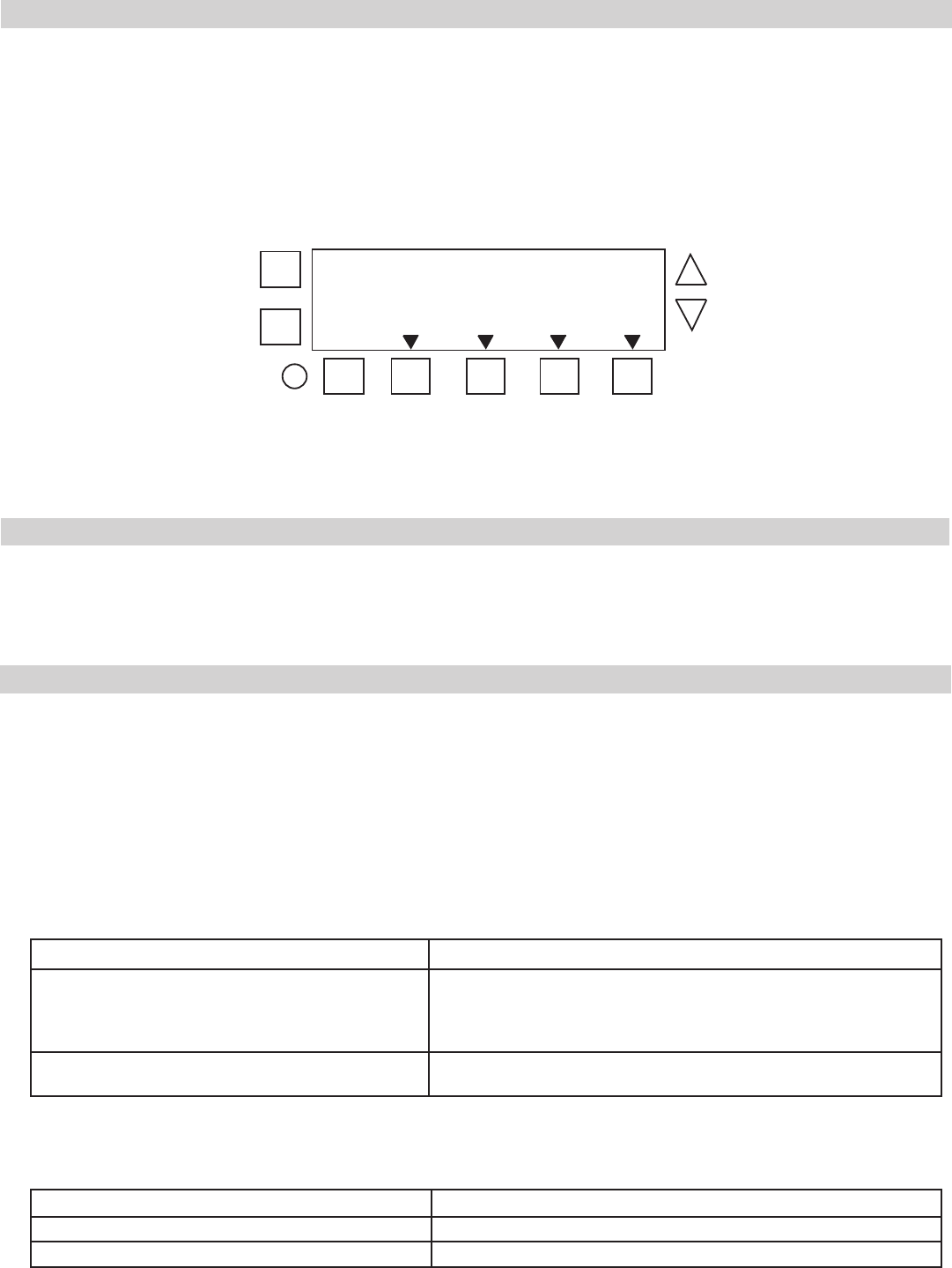
Press MODE to scroll through the menus and program the current date, time, Astro zone, Astro events, and xed events.
Press + or - to congure the rst part of a setting, such as MONTH. Press the ENTER/NEXT button to move to the next part of the
setting, such as YEAR, and then press MODE to exit and move to the next menu. Press MODE to skip a menu, correct an entry, and
scroll back to an error, and adjust.
NOTE: If the time switch is left inactive for five minutes in a programming mode, it will return to the time of day screen. If no
events are programmed, the time switch will return to manual mode.
Initial Setup
The following sections provide instructions for the initial setup of the time switch.
Setting Date and Time
Follow this procedure below to set the date and time in the time switch.
NOTE: If necessary, hold + or - to scroll through the digits rapidly.
1. Press MODE to scroll through the menus until SET and DATE appear at the top of the display. The month ashes.
2. Press + or - to select the current month and then press ENTER/NEXT. The day of the month ashes.
3. Press + or - to select the current day of the month, and then press ENTER/NEXT. The year ashes.
4. Press + or - to enter the current year, and press ENTER/NEXT.
5. Press MODE to advance to the set clock screen. A ashing 12:00 appears.
6. Press + or - to enter the current time and press MODE to save and exit.
Programming Overview
Enable/Disable Daylight Saving Time and Setting Daylight Saving Time Rule
Congure the time switch to automatically adjust for Daylight Saving Time (DST). If DST does not apply to your region, disable the option
as directed in this procedure. Follow this procedure to enable/disable the Daylight Saving Time, and if applicable, set the DST rule.
1. Press MODE to scroll through the menus until SET and DST appear.
2. Press + or - to display ON (enable DST) or OFF (disable DST) and then press ENTER/NEXT to save.
3. Take one of these actions.
If DST is... Then...
Enabled, Go to step 4.
Disabled, Press to MODE exit. The procedure is complete.
4. Press + or - to scroll to the desired time zone rule.
NOTE: The time zone rules are US2007 (US time zone rules), MX1986 (Mexico time zone rules), and CUSTOM (user-defined time
zone start/end dates).
NOTE: To view the start and end dates for a time zone rule, press ENTER/NEXT to scroll through the dates.
Setting Astro Zone and Time Zone Mode
The Astro Zone command enables users to set the geographical location (country, state or province, and quadrant). of the time switch.
Follow this procedure to set the Astro Zone for the time switch.
1. Press MODE to scroll until ASTRO ZONE appears at top of the screen. The screen displays AL and C and a ashing USA.
2. Press + or - to select the country (USA, Canada, or Mexico) and press ENTER/NEXT.
3. Take one of these actions.
If you selected... Then...
USA or Canada, Press + or - to select the desired state or province and press ENTER/
NEXT. Go to step 4.
Mexico, Go to step 4.
4. Press + or - to select to the applicable quadrant and press ENTER/NEXT. The LAT (latitude) screen appears.
NOTE: Each state, province, and country are divided into geographical quadrants. Choose the quadrant that is most ap-
plicable to your location. The number of quadrants vary by state, province, and country.
5. Determine if the latitude for your location needs to be set.
NOTE: In most cases, the quadrant provides an accurate location for your time switch. Certain states require a latitude and longi-
tude to be set in the time switch. If this is a requirement, follow the applicable steps to set a latitude and longitude.
6. Take one of these actions.
If... Then...
Latitude needs to be set, Press + or - to select the latitude and press ENTER/NEXT.
The longitude screen appears. Go to step 7.
Latitude does not need to be set, Press ENTER/NEXT to scroll past the latitude and longitude
screens to the TZCENT screen. Go to step 8.
NOTE: If necessary, press + or - simultaneously to return to the region screen.
7. Press + or - to select the longitude and press ENTER/NEXT. The TZCENT screen appears.
8. Press + or - to scroll to select the required time zone and press ENTER/NEXT. See table for a description of the time zones.
Time Zone Options Description
TZ HAI Hawaiian time zone
TZ ALS Alaskan time zone
TZPACI Pacific time zone
TZMntN Mountain time zone
TZCENT Central time zone
TZEAST Eastern time zone
TZATLN Atlantic time zone
TZNFLD Newfoundland time zone
9. Press MODE to save the settings.
5. Take one of these actions.
If you select... Then...
US2007 or MX1986, Go to step 10.
Custom, Press ENTER/NEXT. The screen displays a flashing MAR and 2ND.
Go to step 6.
6. Press + or - to select a starting month for customized DST and press ENTER/NEXT.
7. Press + or - to select a starting week (1st, 2nd, 3rd, 4th, or LST) and press ENTER/NEXT.
NOTE: DST begins at 2:00 A.M. on Sunday of the user-configured starting and ending weeks. Select LST for the fifth a Sunday of a month.
8. Press + or - to select an ending month and press ENTER/NEXT.
9. Press + or - to select and ending week and press ENTER/NEXT.
10. Press MODE to save the DST rule and exit.
Setting Astro On/Off Events
Access the Astro Events screen to congure Astronomic ON/OFF events for days of the week and circuits. The time switch enables one
Astronomic ON (at sunset) and one Astronomic OFF (at sunup) per day of the week for each load. Follow this procedure to set Astro ON/
OFF Events.
1. Press MODE to scroll to SET ASTRO ON/OFF EVENTS.
2. Press DAY. The screen displays SUNSET (or SUNUP), the days of the week, and the load number.
NOTE: If you are creating an Astro event as directed in Setting Astronomic and Fixed Events, press ENTER/NEXT to adjust be-
tween SUNSET or SUNUP.
3. Press DAY to select the days (MON-SUN, MON-FRI, SAT-SUN), or a user-congured group of days) you want the Astro event to
occur.
4. The screen displays the congured days under SUNSET or SUNUP. Press DAY to add or remove a group of days. To select indi-
vidual days, press DAY and scroll through options until ON and MON ash on the screen.
5. Take one of these actions.
If you select... Then...
MON-SUN, MON-FRI, SAT-SUN, Press ENTER/NEXT to save.
Go to step 6.
NOTE: If you are performing the procedure Setting Astronomic and
Fixed Events, return to step 2 of the procedure.
Individual days, (ON and MON), Press + or - to select Astro event ON or -- (OFF) for the flashing day
of the week and press DAY. Go to step 5.
6. Repeat the process for each day of the week. When all the individual days are congured, press ENTER/NEXT to save.
NOTE: If you are performing the procedure Setting Astronomic and Fixed Events, return to step 2 of the procedure.
7. Repeat steps 3 through 5 to congure SUNUP OFF. When both SUNSET and SUNUP are set, go to step 7.
8. Take one of these actions:
If... Then...
You want to configure an Astro event for another load, Press ENTER/NEXT. Repeat steps 3 through 6.
All the required Astro events are set, Press MODE to exit. The procedure is complete.
Users can congure Astro events, xed timed events, or a combination of Astro and xed timed events.
Perform the applicable instructions below.
-To set Astro events only, perform the procedure Setting Astro On/Off Events
-To set xed timed events only, perform the procedure Setting Fixed Timed Events
-To set a combination of Astro and xed events, perform the procedure Setting Astronomic and Fixed Events
Setting Astro and Fixed Events
5. Repeat steps 2 through 4 as needed to congure times for additional loads.
6. When all the loads are set, press MODE to save the settings. The time switch displays SET SUNSET at the top of the screen and
LOAD 1.
7. Repeat steps 2 through 6 as necessary to set sunset times.
8. When all the sunup and sunset times are congured, press MODE to save.
Setting Sunup and Sunset Times
Multiple sunrise and sunset offsets can be congured for different areas in a facility. For example, a user can congure a sunrise offset for
the lights in a parking lot to turn off one hour after normal sunrise.
Follow this procedure to set sunup and sunset times.
1. Press MODE and scroll until SET SUNUP appears at the top of the screen. The default time for the LOAD appears.
2. Press + or - to adjust the time for the sunup or sunset and press ENTER/NEXT. The OFFSET screen appears, followed by the
offset time digit (in minutes).
3. Press + or - to adjust the offset and press ENTER/NEXT to save.
NOTE: Offsets can be set to a maximum of 2 hours (120 minutes) before or after a sunup or sunset time. A minus sign (-) appears
before the digit to indicate minutes before the sunup or sunset time.
4. If applicable, press the next ON/OFF button in sequence for the next load.
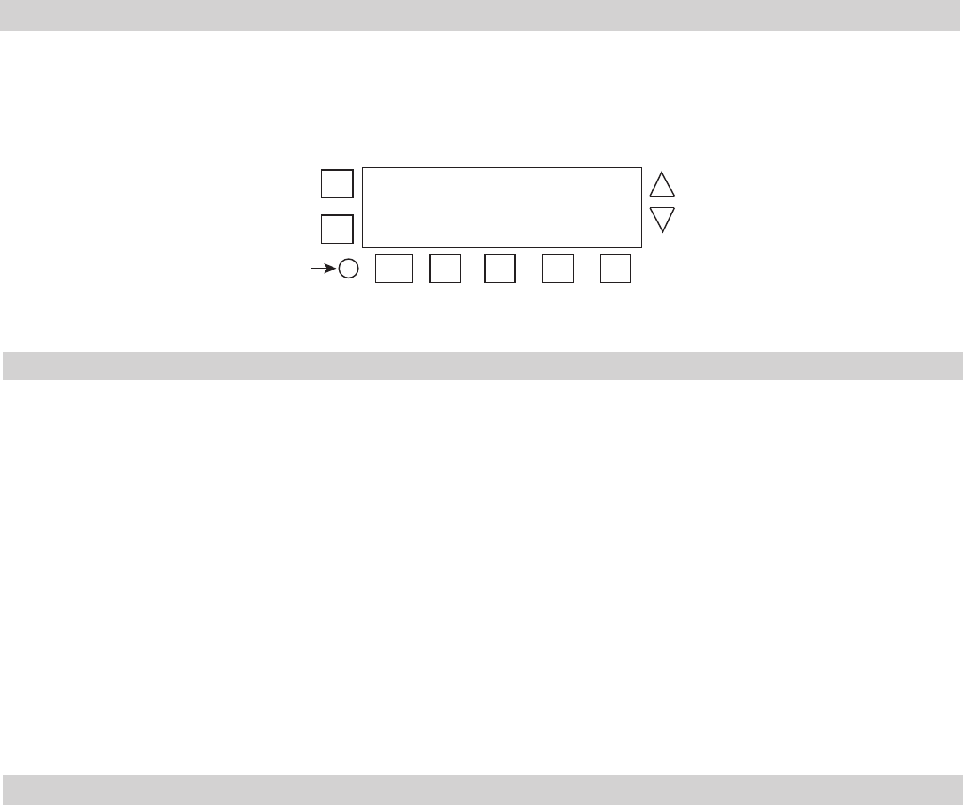
+
-
ENTER
NEXT
ON/
OFF
ON/
OFF
ON/
OFF
ON/
OFF
MODE
DAY LOAD LOAD LOAD LOAD
1 2 3 4

To combine Astronomic and xed events, only program one event in each ON/OFF event pair for both Astro and Fixed events. For
example, a combination Astro and xed event schedule could be a Sunset ON and a Fixed event off for 10 P.M. It is recommended to
determine your facility schedules in advance and then program the time switch. If applicable, different combinations can be congured
for different loads.
Follow these guidelines to congure a combination Astro and Fixed Event schedule.
1. Program the Sunset ON or Sunup OFF events for the applicable loads as instructed in Setting Astro On/Off Events.
NOTE: After a Sunset or Sunup is configured, be sure to leave the other On or Off event blank.
2. Press MODE to scroll to SET FIXED ON/OFF.
3. Program the Fixed ON or Fixed OFF events for the applicable loads as instructed in Setting Fixed Timed Events.
NOTE: After a Fixed ON or OFF is configured, be sure to leave the other ON or OFF event blank.
4. When all the schedules are complete, press MODE to exit the xed event screen.
Daily Operation
Perform the Daily Operation procedures as needed. They include resetting the controller, deleting an event, and clearing time switch
Deleting (Clearing) an Event
Astro events and xed timed events can be deleted from the time switch. If you need to delete an event, follow this procedure.
1. If necessary, press MODE to scroll through the menus to SET ASTRO or SET FIXED ON/OFF EVENTS screen.
2. Press ENTER/NEXT as necessary to scroll through the scheduled events until you see the event you want to delete.
3. Press + and - AT THE SAME TIME to display --:-- --. This indicates the event is erased.
4. Press MODE to exit.
Setting Astronomic and Fixed Events
6. Repeat the process for each day of the week. When all the individual days are congured, press the applicable ON/OFF buttons
for the applicable loads that you want to include with the xed timed event.
7. Press ENTER/NEXT to save.
NOTE: If you are performing the procedure Setting Astronomic and Fixed Events, return to step 4 of that procedure.
8. Repeat steps 2 through 7 to set the xed OFF event. After both xed on and xed off are set, go to step 9.
9. Take one of these actions:
If... Then...
Another xed timed event needs to be set, Repeat steps 2 through 8.
All the events are set, Press MODE to exit. Go to step 10.
10. Press MODE to place the time switch in AUTO (Mode). This enables the time switch to automatically initiate congured
scheduled events.
NOTE: In AUTO Mode, the time switch follows the user-configured events, and the circuits turn ON and OFF at the configured
time(s). In MANUAL mode, the time switch does not follow user-configured events and only activates circuits when an ON/
OFF button is pressed. Press MODE again to return the controller to MANUAL mode.
NOTE: Press ON/OFF to override a program in Auto Mode. After a program is overridden, the time switch returns to the normal
schedule.
Setting Fixed Timed Events
Access the Fixed ON/OFF screen to set xed switching times. Odd-numbered events are for ON switching and even-numbered events
are for OFF switching. Follow these steps to set xed time events.
1. Press MODE to scroll until SET FIXED ON@ appears on the screen.
2. Press DAY. The screen displays 12:00 am, the days of the week, and the event number.
NOTE: If you are performing the procedure Setting Astronomic and Fixed Events, press ENTER/NEXT to adjust between Fixed
ON@ and Fixed OFF@ and then press DAY.
3. Press + or - to set the starting time for the xed event.
4. Press DAY to select the days (MON-SUN, MON-FRI, SAT-SUN), or a user-congured group of days) you want xed event to oc-
cur.
NOTE: To select the individual days, press DAY to scroll through the options until ON and MON flash on the screen.
5. Take one of these actions.
If you select... Then...
MON-SUN, MON-FRI, SAT-SUN, Press ENTER/NEXT to save. Go to step 8.
NOTE: If you are performing the procedure Setting Astronomic and Fixed Events,
return to step 4 of that procedure.
Individual days Press + or - to select event ON or event -- (OFF) for Monday and press DAY. Go
to step 6.
Time Switch
• Input Voltage: 120 to 277 VAC, 50/60 Hz
• Power Consumption: 7 watts maximum
• Contact Conguration: SPST x 4. See wiring diagrams in this manual
N.O. Contact Ratings:
Resistive: 30 Amps @ 120/240 VAC, 60 Hz
Resistive: 20 Amps @ 28 VDC
Inductive: 30 Amps @ 120/240 VAC
Tungsten: 5 Amps @ 120/240 VAC
Ballast: 20 Amps @ 120-277 VAC
Motor: 1 HP @ 120 VAC
Motor: 2 HP @ 240 VAC
Events—Time switch can support up to 28 timed ON and 28 timed OFF events and 4 Astro ON and 4 Astro OFF events.
Clock Backup—100-hour Supercapacitor
Minimum ON or OFF time—1 minute
Maximum ON or OFF time—Indenite
Shipping Weight—2.5 lb. (1.1 kg)
Enclosures—Type 3R indoor/outdoor lockable metal enclosure
Knockouts—Combination 1/2-3/4 inch size, 1 on back and each side, 2 on bottom
Wire Size—AWG #10 through #18
Specifications
Clearing Time Switch Memory
During a memory clear, the time switch performs the same actions as a reset, but also clears all user settings, except the custom Day-
light Savings Time settings. To perform a memory clear do the following:
1. Press and hold ENTER/NEXT.
2. While pressing and holding ENTER/NEXT, press and release the reset button. Do not release ENTER/NEXT.
3. Continue to press and hold ENTER/NEXT until MEM CLEAR and DONE appear, followed by the congured operational mode
setting.
In addition, the following occurs:
4. The time of day is reset to January 1 at 12:00 A.M.
• The timer returns to Manual Mode
• The operational settings can be adjusted
• The Astronomical zone defaults to AL (Alabama) and CNT (center).
• The Astronomical user offsets are set to zero.
• All scheduled switching activity settings are erased.
• All calender information is erased.
• The display ashes as described in the reset procedure.
Resetting the Time Switch
To perform a reset, press the reset button. The following occurs:
• All display segments activate for one second, then the timer model number appears, followed by the rmware revision.
• The current operational mode setting appears for the rst two relays, followed by the current setting for the last two relays.
• The time switch defaults to Manual Mode.
• The time of day resets to 12:00 AM and the day of the week ashes.
+
-
ON/
OFF
ON/
OFF
ON/
OFF
ON/
OFF
MODE
DAY
Reset
button
ENTER
NEXT
LIMITED ONE-YEAR WARRANTY
If within the warranty period specified, this product fails due to a defect in material or workmanship, Intermatic Incorporated will repair or replace it, at its sole
option, free of charge. This warranty is extended to the original purchaser only and is not transferable. This warranty does not apply to: (a) damage to
units caused by accident, dropping or abuse in handling, acts of God or any negligent use; (b) units which have been subject to unauthorized repair,
opened, taken apart or otherwise modified; (c) units not used in accordance with instructions; (d) damages exceeding the cost of the product; (e) sealed
lamps and/or lamp bulbs, LED’s and batteries; (f) the finish on any portion of the product, such as surface and/or weathering, as this is considered
normal wear and tear; (g) transit damage, initial installation costs, removal costs, or reinstallation costs.
INTERMATIC INCORPORATED WILL NOT BE LIABLE FOR INCIDENTAL OR CONSEQUENTIAL DAMAGES. SOME STATES DO NOT ALLOW
THE EXCLUSION OR LIMITATION OF INCIDENTAL OR CONSEQUENTIAL DAMAGES, SO THE ABOVE LIMITATION OR EXCLUSION MAY NOT
APPLY TO YOU. THIS WARRANTY IS IN LIEU OF ALL OTHER EXPRESS OR IMPLIED WARRANTIES. ALL IMPLIED WARRANTIES, INCLUDING
THE WARRANTY OF MERCHANTABILITY AND THE WARRANTY OF FITNESS FOR A PARTICULAR PURPOSE, ARE HEREBY MODIFIED TO
EXIST ONLY AS CONTAINED IN THIS LIMITED WARRANTY, AND SHALL BE OF THE SAME DURATION AS THE WARRANTY PERIOD STATED
ABOVE. SOME STATES DO NOT ALLOW LIMITATIONS ON THE DURATION OF AN IMPLIED WARRANTY, SO THE ABOVE LIMITATION MAY NOT
APPLY TO YOU.
This warranty service is available by either (a) returning the product to the dealer from whom the unit was purchased, or (b) completing a warranty claim
on line at www.intermatic.com. This warranty is made by: Intermatic Incorporated Customer Service/7777 Winn Rd., Spring Grove, Illinois 60081-9698 /
815-675-7000 http://www.intermatic.com
INTERMATIC INCORPORATED
7777 Winn Road
SPRING GROVE, ILLINOIS 60081-9698
www.intermatic.com
158--01109
