Intermec Technologies IM11 IM11 User Manual IM4 IG revs
Intermec Technologies Corporation IM11 IM4 IG revs
UserManual.wiki
>
Intermec Technologies
>
IM11 User Manual
>
User Manual
Contents
1.
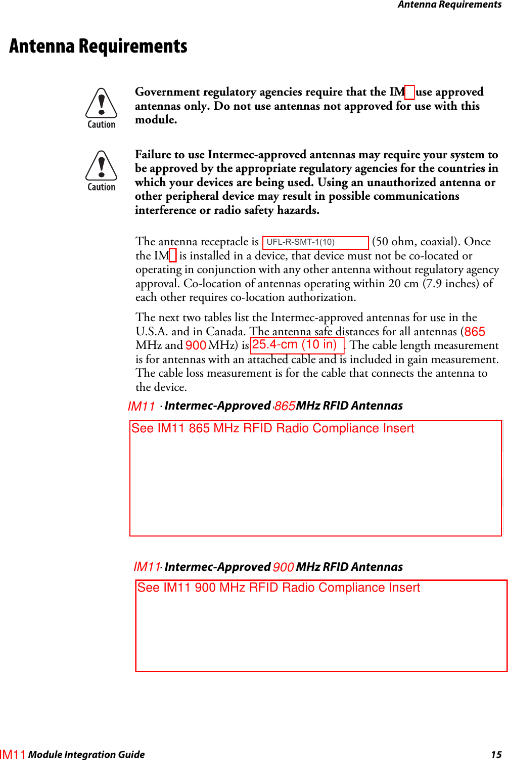
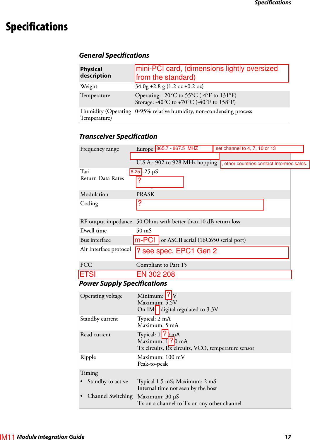
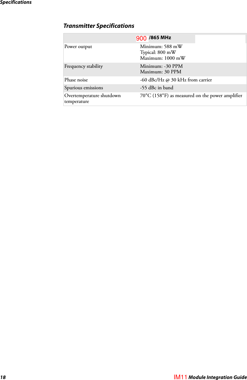
Compliance Insert
2.
User Manual
3.
user manual
4.
user Manual
User Manual
Navigation menu
Upload a User Manual
Namespaces
Wiki Guide
HTML
PDF
Info
Views
User Manual
Discussion / Help
Navigation